
CC-2011E - Rear Camera CLARION - Free user manual and instructions
Find the device manual for free CC-2011E CLARION in PDF.


| Product Type | Rear View Camera |
| Brand | Clarion |
| Model | CC-2011E |
| Image Sensor | 1/3-inch CMOS |
| Resolution | 720 x 480 (NTSC) / 720 x 576 (PAL) |
| Viewing Angle | 120° (diagonal) |
| Minimum Illumination | 0.1 lux |
| Video Output | 1.0 Vp-p, 75 ohms, RCA jack |
| Power Supply | 12V DC (negative ground) |
| Current Consumption | ≤ 150 mA |
| Operating Temperature | -20°C to 70°C |
| Waterproof Rating | IP68 |
| Dimensions (W x H x D) | Approx. 2.5 x 2.5 x 2.5 inches (64 x 64 x 64 mm) |
| Weight | Approx. 5.6 oz (160 g) |
| Mounting Type | Surface mount or flush mount |
| Mirror Image | Yes, switchable for front/rear use |
| Parking Guide Lines | Adjustable overlay |
| Cleaning | Wipe gently with a soft, dry cloth; avoid harsh chemicals |
| Safety | Install such that camera does not obstruct driver's view |
| Spare Parts Availability | Contact Clarion authorized dealer for replacement cables or brackets |
| Repairability | Serviceable by qualified technician; no user-serviceable parts inside |
Frequently Asked Questions - CC-2011E CLARION
User questions about CC-2011E CLARION
0 question about this device. Answer the ones you know or ask your own.
Ask a new question about this device
Download the instructions for your Rear Camera in PDF format for free! Find your manual CC-2011E - CLARION and take your electronic device back in hand. On this page are published all the documents necessary for the use of your device. CC-2011E by CLARION.
USER MANUAL CC-2011E CLARION
Owner's manual & Installation manual
Vehicular Rear-View Color Camera
Thank you for purchasing this Clarion product.
* Please read this owner's manual in its entirety before operating this equipment.
* After reading this manual, be sure to keep it in a handy place (e.g., glove compartment).
* Check the contents of the enclosed warranty card and keep it carefully with this manual.
Contents
- FEATURES....2
- PRECAUTIONS ....3
- SPECIFICATIONS 4
Package Contents 4 - OPERATIONS ....5
Operation when using Clarion rear-view camera system 5
Troubleshooting 5 - INSTALLATION 6
Before installation 6
Precautions when using two-sided tape for installation 6
Installing/Wiring the camera 6 - WIRING 8
■ High-performance 1/4" color CCD solid-state imaging element
■ Wide-angle lens, allowing broad field of view
■ High-resolution glass lens for high image quality
■ Mirror-image inversion function presents optimum conditions for confirming rear view (same right-left orientation as seen through a rear-view mirror)
■ Small size and weight for easy installation
2. PRECAUTIONS
INFORMATION FOR USERS:
CHANGES OR MODIFICATIONS TO THIS PRODUCT NOT APPROVED BY THE MANUFACTURER WILL VOID THE WARRANTY.
This equipment has been tested and found to comply with the limits for a Class B digital device, pursuant to Part 15 of the FCC Rules. These limits are designed to provide reasonable protection against harmful interference in a residential installation. This equipment generates, uses, and can radiate radio frequency energy and, if not installed and used in accordance with the instructions,
may cause harmful interference to radio communication. However, there is no guarantee that interference will not occur in a particular installation. If this equipment does cause harmful interference to radio or television reception, which can be determined by turning the equipment off and on, the user is encouraged to consult the dealer or an experienced radio/TV technician for help.
!
- This device has been designed exclusively for use with a vehicular mounted rear-view television system. It should not be used for other purposes.
- Disconnect the vehicle's negative (−) terminal when installing wiring.
- Do not attempt to disassemble or modify this product.
- In the event it is necessary to drill holes in the vehicle for mounting, confirm that the drill bit or camera wiring will not strike or interfere with piping, gas tank, electrical wiring or other functional parts of the vehicle.
- Do not rely solely on the monitor image when reversing the vehicle.
The rear-view monitor is an auxiliary device meant for confirming the presence of obstacles to the rear of the vehicle, and is limited in its range. It should be used only in conjunction with direct visual observations.
• Always reverse at low speeds.
The rear-view monitor produces a wide-angle image, with the result that actual distances may be different than they subjectively appear in the monitor. - Do not use when the imaging surface or other parts are malfunctioning.
- When installation and wiring are completed, confirm that the vehicle's horn, brake and warning lights, and other electrical equipment function properly as designed.
!
CAUTIONWARNING
- Install only as directed in the Installation Manual.
- Install accessory parts as directed.
- When drilling holes in the vehicle for installation of wiring, always use insulated grommets in the holes to protect the wiring.
- If holes are drilled in the vehicle to install the camera, or when installing wiring, use silicon sealant to seal any gaps.
- Do not damage or scar the camera wiring.
- After completing the camera wiring, use cable clamps or insulation tape to bundle the wiring together.
- The images produced from the rear-view monitor are inverted right-left in the same way as images seen in the vehicle's rear-view mirrors. The image may differ depending on the vehicle type.
- Do not use high-pressure car washing devices around the camera.
The camera is a high-precision instrument and should not be subjected to high-pressure water stream impacts. - Periodically check the tightness of the installation screws and retighten if necessary.
3. SPECIFICATIONS
Power source/voltage: DC 9 V (±0.5 V)
Power consumption: 120 mA or less
Image sensor: 1/4" solid-state color CCD
Angle of view: About 130° (horizontal)
About 97^ (vertical)
Minimum subject illumination: 3 LUX or less (2 LUX ±1 LUX)
SN ratio: 48 dB or more (AGC-OFF)
Weight: About 72 g (bracket and 0.5 m cable)
Dimensions: 27 (W) × 25 (H) × 28.3 (D) mm
Note:
- Specifications and design are subject to change without notice for further improvement.
Package contents
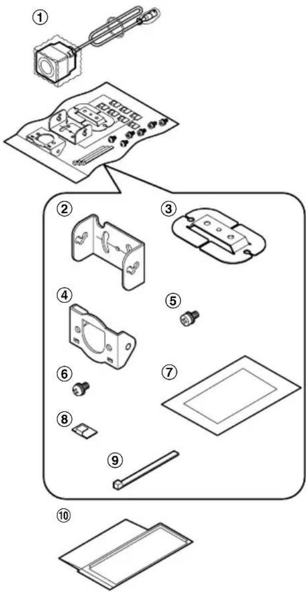
① Camera (with 0.5 m cable) .... 1
② Mounting bracket A .... 1
③ Mounting bracket B .... 1
④ Mounting bracket C 1
⑤ Installation screws (hex head M3 x 6)...... 4
⑥ Installation screws (pan head M3 x 6) ..... 2
⑦ Cleaning fluid (for use in preparing surface for 2-sided tape) .... 1
⑧ Cable holders 7
⑨ Cable clamps 3
⑩ Owner's manual & Installation manual ..... 1
4. OPERATION
Operation when using Clarion rear-view camera system
The rear-view image is displayed when the transmission is placed into reverse, or when the manual switch is operated.
Troubleshooting
The following symptoms are not malfunctions. Before having the unit serviced, check the following points once more.
| Symptom | Reason | Solution |
| No image | Wiring is incomplete or disconnected. | Check wiring once again and confirm correct connections. |
| A fuse is burned out. | When using an independent power supply box, check the fuse and, if burned out, replace with a new one of the same capacity (1 A). If the fuse burns out repeatedly, consult your dealer or nearest Clarion Service Center. | |
| Poor image is produced | The lens cover is soiled. | Wipe lightly with a damp soft cloth. Do not rub harshly with dry cloths since scratches may be produced. |
| Sunlight or headlights from a vehicle in the rear are shining directly in the camera. | The image will return to normal when the light striking the lens is removed. | |
| The environment is too dark. | The image display will be poor at night or in dim light.The image will return to normal in conditions of brighter illumination. | |
| The level of illumination outside the vehicle changed too abruptly.1. When moving from a bright to a dark location (especially from bright sunlight to shade), the image may appear excessively dark.2. When moving from a dark to a bright location (especially from shade into bright sunlight), the screen image may appear excessively bright. | [When using a separate power supply box]• In auto modeStop the vehicle and set the transmission to neutral, then once again to reverse.• In manual modePress the AUTO/MANUAL switch to set the unit to AUTO, then press once again to set to MANUAL. If the transmission is in reverse, set it to neutral before pressing the switch. |
5. INSTALLATION
Before installation
- Before installing the camera or its wiring, read all safety warnings and be sure to install the unit correctly.
- Before installing the camera permanently, use adhesive tape to mount the camera in its proposed position, then check the image in the monitor to confirm proper display before fixing the camera in its final position.
WARNING
- Disconnect the battery's negative (−) terminal installing wiring.
Precautions when using two-sided tape for installation
■ Do not install on glass or body surfaces treated with fluorinated resins or other water-repellent treatments.
- Do not install within the sweep of a rear-window wiper, or near the window washer's nozzle.
- Abide by the following rules in order to prevent lowering of the installation tape's adhesion:
- As far as possible, install on a day with clear weather.
- Within the first 24 hours after installation, do not expose the installation to moisture (water, rain, mist, snow, etc.), or subject the installation to strong forces or impacts.
- When installation must be performed under conditions of low ambient temperature (20°C or below), use a hair dryer to warm the surface of the bracket where the 2-sided tape is to be applied.
- Do not touch the bracket-mounting surface's 2-sided tape, and do not attempt to move or reset the tape after initial application.
Installing/Wiring the camera
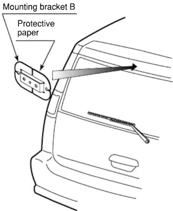
1. Install mounting bracket B
Use the supplied cleaner to clean the vehicle surface to which the bracket is to be applied, then remove the protective paper from the mounting surface of bracket B and press securely onto the vehicle surface.
Notes:
- Before using the supplied cleaner, read the label on the cleaner container thoroughly.
- Do not wipe the camera body with the cleaner, since it may be discolored or otherwise damaged.
- Before removing the protective paper on the bracket, place it in the proposed position on the vehicle and confirm that the surfaces match properly without gaps.
- When using screws to install the bracket, use the right-left screw holes provided on bracket B.
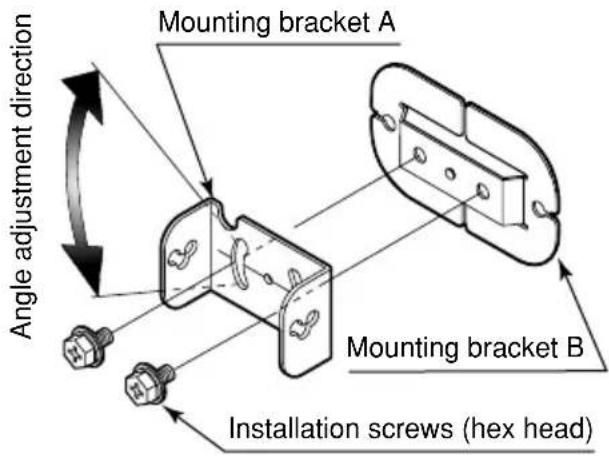
2. Install mounting bracket A
Using the supplied 2 installation screws (hex head M3 x 6), fasten bracket A to bracket B.
- While tightening the screws, adjust the angle of the bracket A to produce the optimum camera angle.
To mount the camera at a level angle, mount bracket A's engraved leveling line (——) even with the center of the installation screws when tightening.
3. Attach mounting bracket C to camera
Using the two pan head installation screws (M3 x 6), attach the camera to mounting bracket C, using the two hex head installation screws (M3 x 6) as shown, attach the camera and bracket C assembly to mounting bracket A.
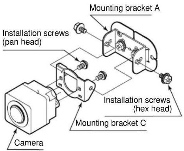
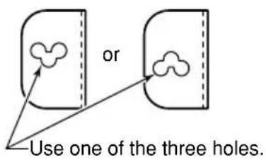
- Adjust the camera angle as desired when tightening the screws for mounting bracket C. The camera's position can be adjusted by selecting from among the three sets of holes on the sides of mounting bracket A.
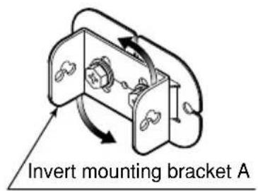
In addition, the mounting bracket A can be inverted (mounted upside down) if needed to provide additional range of camera installation.
CAUTION
- When adjusting the camera position, do not allow the camera cable to be excessively stretched or loose.
- Periodically check the tightness of the installation screws and retighten if necessary.
■ Adjusting camera angle (example)
CAUTION
When the camera angle has been changed, the range displayed by the image on the monitor will change. Always confirm by direct observation when backing the vehicle.
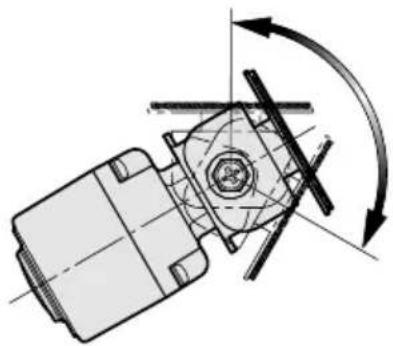
natural_image
Mechanical assembly diagram showing a rotating component with directional arrows indicating motion (no text or labels)Adjust the angle of brackets A+B as required by the mounting position.
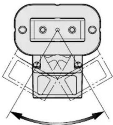
natural_image
Technical diagram of a mechanical component with alignment arrows, no visible text or symbolsAdjust horizontal angle while confirming image on monitor.
6. WIRING
Wiring
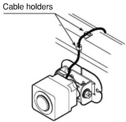
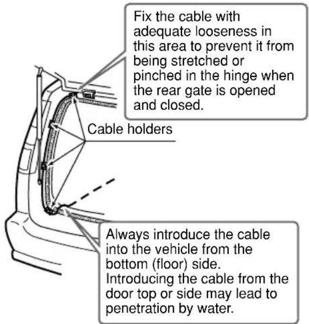
① Lead the camera cable into the vehicle and align it along the vehicle weather stripping. Use the supplied cable holders as necessary to fix the wires in place and prevent them from being pinched in hinges or dampers.
② Using an optional extension cable, the camera cable can be installed under the vehicle floor (carpet) to connect to a Clarion rear-view monitor or independent power supply box (CAA-188).
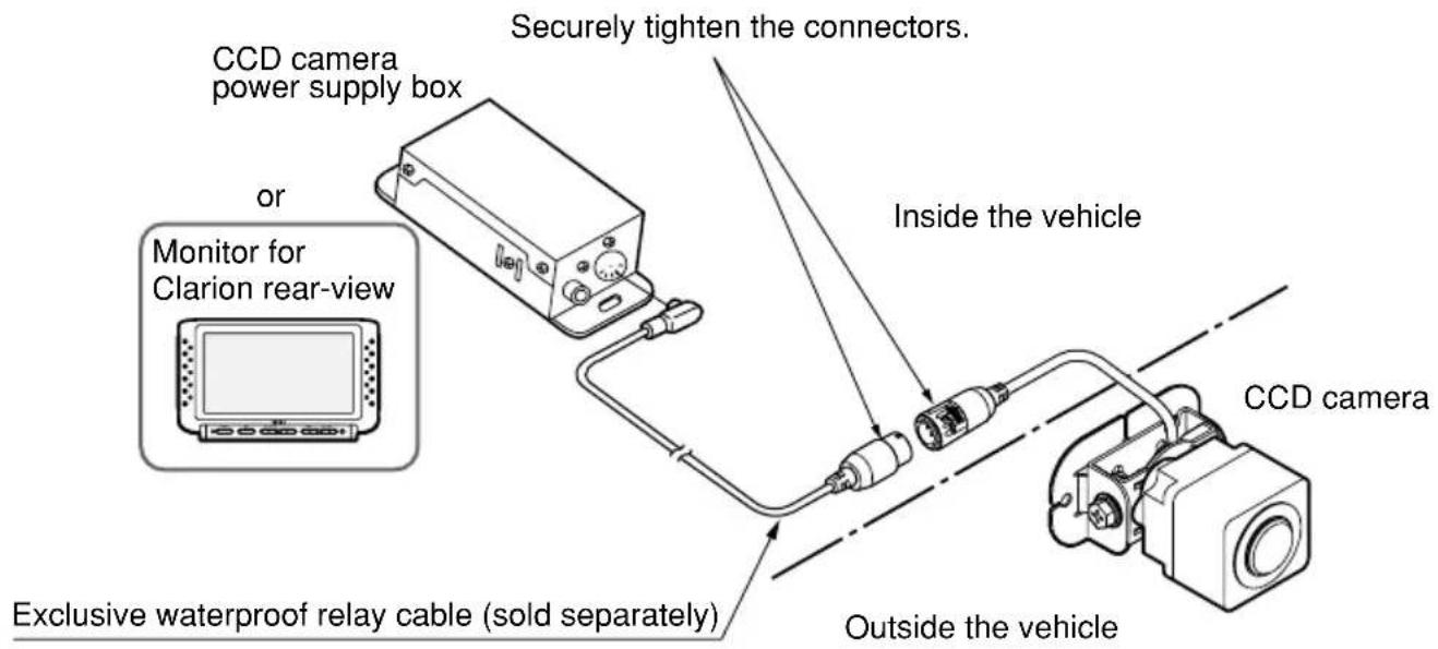
CCA-532-100 (7 m) CCA-533-100 (10 m) CCA-534-100 (15 m)
Note:
• See the Instruction Manual supplied with the monitor for information regarding wiring, operation, and composition of the monitor unit.
■ Waterproof Connector Fastening Procedure and Cautions
① ▲ Mark : Align the arrow marks on both connectors in order to connect the cable.
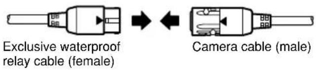
② Hold the two connectors together and twist the ring on the camera cable's connector as far as it will go.
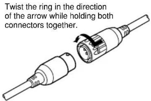
CAUTION
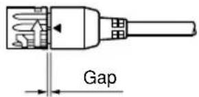
Twist the yellow ring until there is no gap between the ring and the connector.
Should there be any gap between the ring and the connector, twist the ring to close it.


- Contents
- PRECAUTIONS
- INFORMATION FOR USERS:
- !
- CAUTIONWARNING
- SPECIFICATIONS
- Note:
- Package contents
- OPERATION
- Operation when using Clarion rear-view camera system
- Troubleshooting
- INSTALLATION
- Before installation
- WARNING
- Precautions when using two-sided tape for installation
- Installing/Wiring the camera
- Install mounting bracket B
- Notes:
- Install mounting bracket A
- Attach mounting bracket C to camera
- CAUTION
- ■ Adjusting camera angle (example)
- WIRING
- Wiring
- ■ Waterproof Connector Fastening Procedure and Cautions
Brand : CLARION
Model : CC-2011E
Category : Rear Camera