
MobiSet 4 Twin CAP 920 - Satellite receiver KATHREIN - Free user manual and instructions
Find the device manual for free MobiSet 4 Twin CAP 920 KATHREIN in PDF.


| Product Type | Mobile satellite receiver system with automatic positioning |
| Brand | Kathrein |
| Model | MobiSet 4 Twin CAP 920 |
| Receiver Unit | UFS 946/CI+ HDTV DVB-S receiver |
| Dish Diameter | Approx. 75 cm |
| Total Weight (Turntable + Dish) | 18.9 kg |
| Power Supply | 12 V DC (vehicle battery), 11.5 – 13.8 V |
| Power Consumption (Standby) | Typ. 1.2 A |
| Power Consumption (Search) | Typ. 3 A |
| Max Inrush Current | 12 A (300 ms) |
| Fuse Rating | 15 A blade fuse (included) |
| Frequency Range | 10.70 – 12.75 GHz |
| LNB Type | Twin LNB with 2 switchable outputs (V/H, Low/High) |
| Automatic Skew | Yes, GPS-based |
| Elevation Range | 3° – 67° |
| Azimuth Range | 390° continuous |
| GPS Receiver | Integrated for automatic location detection |
| Max Vehicle Speed (Antenna Deployed) | 130 km/h |
| Operating Temperature Range | -20 °C to +45 °C |
| Cable Lengths (Coax) | 2 x 8 m |
| Power Cable Length | 10 m |
| Mounting Plate Dimensions | Requires free area 1024 x 1250 mm |
| Adhesive Sealant Included | DEKAsyl MS (100 ml tube) |
| Warranty | Subject to proper installation and use |
Frequently Asked Questions - MobiSet 4 Twin CAP 920 KATHREIN
User questions about MobiSet 4 Twin CAP 920 KATHREIN
0 question about this device. Answer the ones you know or ask your own.
Ask a new question about this device
Download the instructions for your Satellite receiver in PDF format for free! Find your manual MobiSet 4 Twin CAP 920 - KATHREIN and take your electronic device back in hand. On this page are published all the documents necessary for the use of your device. MobiSet 4 Twin CAP 920 by KATHREIN.
USER MANUAL MobiSet 4 Twin CAP 920 KATHREIN

IMPORTANT
READ CAREFULLY BEFORE USE
Contents
Installation Manual
1 General....4
2 MobiSet 4 CAP 920 components / scope of delivery....5
3 Proper Use....6
4 Safety Instructions – Important Notes ....7
5 Installation and connection....10
5.1 Required tools and equipment 10
5.2 Unpacking and Preparation....10
5.3 Selecting the Installation Location....11
5.4 Installation steps....12
5.5 Brief instructions for installing the turntable....18
5.6 Installation of the UFS 946/Cl+ 20
6 Reception range / footprint 26
7 Dismantling for servicing 27
7.1 Removing....27
7.2 Address of the service centre....27
8 Polarisation setting....28
8.1 Polarisation setting....28
9 Manual lowering to park position....28
9.1 Safety instructions....28
9.2 Manual Retraction 29
10 Technical Specifications....30
11 DEKAsyl MS safety data sheet 32
12 DEKAsyl MS technical data sheet 39
13 Important information for CAP 920 before setup....42
Operating Manual
14 First installation 43
15 CAP menu (polar antenna settings) 48
15.1 Calling up the CAP menu....48
15.2 Move CAP to park position....48
15.3 Resetting the CAP system (polar antenna) (RESET)....48
15.4 CAP settings (main menu) 49
16 Alignment (satellite search)....50
17 Channel (satellite) selection....51
17.1 Channel selection from the channel list....51
17.2 Channel selection from the channel list (sorted by satellite)....52
18 Change of location....53
19 Park 53
20 Special messages from the turntable ....54
20.1 System protection messages....54
20.2 Further messages ....55
21 Declaration of Conformity....56
22 Disposal Instructions....57
1 General
Dear Customer, Chère Cliente, Cher Client, Gentile cliente, Estimado cliente,
GB
You can obtain an English version of our mounting instructions from our representatives in your country 1) or download one from our web site 2) .
F
Company address and accredited representative
KATHREIN-Werke KG
Personally liable Managing Director of
KATHREIN-Werke KG
2 MobiSet 4 CAP 920 components / scope of delivery

Scope of supply
The MobiSet 4 CAP 920 consists of:
- Turntable complete with control electronics (and GPS receiver), pre-assembled satellite dish and twin LNB, automatic skew
- Mounting plate
- Complete cabling set: 2 x coax cables each 8 m long, and one power supply cable (10 m) for connection to the on-board power supply (incl. blade-type fuse 15 A)
• Roof duct with sealing gasket
• DEKAsyl MS adhesive sealant (100 ml tube) - HDTV-DVB-S receiver UFS 946/CI+ 1) with connecting cables, infrared sensor, infrared remote control and installation kit
• MobiSet 4 CAP 920 installation manual - Operating manual UFS 946/CI+ satellite receiver
1) You can find the rear view and the description of the function and operation in the operating manual of the UFS 946/CI+.
3 Proper Use
The MobiSet 4 CAP 920 is designed to receive digital TV and radio programs via satellite. The automatic positioner is intended to be used as a turntable for the Kathrein satellite dish.
The turntable can be used to receive digital TV and radio signals in the frequency range from 10.70 to 12.75 GHz; the antenna cannot receive terrestrial signals (e.g. DVB-T).
The turntable can only be operated in conjunction with the UFS 946/Cl+ (or UFS 740 and UFS 940) DVB-S receiver.
In conjunction with this receiver, the turntable provides fully automatic alignment of the satellite dish to receive digital satellite signals. The turntable is designed for use on stationary caravans or motor homes.
Any use other than that specified above will invalidate the warranty or guarantee.
The following circumstances result in the loss of all warranty and liability claims towards the manufacturer:
- Improper installation
- Use of non-specified mounting materials, which cannot guarantee the mechanical reliability of the antenna system
- Impermissible use, e.g. use of the reflector dish for storage
- Structural changes or interference with the components and mounting accessories in the set, which could endanger both the mechanical and functional reliability
- Improper or forcible opening of the components
- Use of cleaners containing solvents, such as acetone, nitro-cellulose thinners, petrol, etc.
- Failure to observe installation and safety instructions in this manual
Note
The maximum permissible speed for vehicles with a CAP 920 receiver unit mounted 130 km/h. Before commencing a journey, the antenna must always be lowered into horizontal position (park position).
Important

The turntable may be operated over an ambient temperature range of from -20\ °C to +45\ °C . Operating the system outside this range may result in malfunctions or damage to the system. Ensure that the receiver is adequately ventilated when selecting the installation and setup location.
The system may be installed only by qualified specialist personnel.
To prevent hazards during installation, operation or when driving on public highways, the instructions and information in this manual must be strictly adhered to. Proper installation and connection of the system are pre-requisites for conformity with the corresponding standards.
This is documented in advance by the CE mark and the declaration of conformity in the appendix to this manual.
4 Safety Instructions – Important Notes
Safety during installation work

Warning
Risk of injury or even death through installation work in places with a risk of falling and from falling parts. Please note the following safety points:
- Use a working platform.
- Make sure that the vehicle roof is sufficiently strong and stable to carry out the installation work (risk of damage to or collapsing of the roof).
- In case of doubt, contact a qualified specialist dealer or the manufacturer of your vehicle to find an appropriate installation location.
Please note that there is
- The turntable and connected units are disconnected from the power supply,
- The person carrying out the installation or repair does not suffer from vertigo and can move around safely on the roof of the caravan or motor home,
- The person carrying out the installation or repair is wearing sturdy non-slip shoes,
- The person carrying out the repairs has a secure position to stand and hold on while working,
- The roof and the climbing equipment used (e.g. ladder) are dry, clean and non-slip,
- The roof can withstand the weight of the person carrying out the repairs,
- Nobody should be below the antenna inside the caravan / motor home during dismantling / installation.
Proper installation and safety
Essential information
A crucial safety factor is proper performance of installation and electrical connection work, and the specified alignment of the turntable in the direction of travel (park position), see also installation and connection.
Comply as precisely as possible with the installation conditions and steps described.
Modifications to the electrical installations in the vehicle should only be carried out by a specialist in vehicle electrics. Do not make any unauthorised changes to the turntable.
Adhesive sealant
The turntable is attached to the roof of the vehicle by adhesive and is secured by additional screws. Note that the curing of the adhesive sealant is temperature-dependent. It reaches its full strength only after approximately 2 days.
Important

During installation work, comply strictly with the processing and safety instructions for the adhesive sealant (DEKAsyl MS safety data sheet and the product sheet DEKAsyl MS).
Safety Instructions – Important Notes
Road Traffic Licensing Regulations (StVZO)
The applicable regulations of the German StVZO must be observed in respect of fixed installation of the turntable on a vehicle which is driven on public highways.
In particular, Articles 19/2; 30 C; 32 (2) and EC directive 74/483 EEC are applicable.
Briefly, they state that no endorsement of the vehicle documentation is required unless the antenna causes the height of the laden vehicle to exceed 2 m, or the antenna unit projects beyond the outer lateral outline of the vehicle. The maximum permissible height of 4 m (vehicle and antenna unit) may not be exceeded.

As an increased risk of accidents if the normal vehicle height is increased by extending the antenna. The driver bears sole responsibility for the condition of the superstructure and external fittings!
Cables
Lay all cables such that nobody can tread on them or trip over them.
To prevent parasitic induction or interference emissions, when extending the antenna cable use 75 Ω coaxial cable with a screening factor of at least 75 dB.

If you tied the cables together with wire or similar materials, remove this to prevent the risk of fire!
When connecting the power cables (receiver and turntable) to the vehicle electrical supply, make sure that the cable polarity is not reversed.
Important
If the cable polarity is reversed there is a risk of thermal overload and damage to components when the equipment is powered up!
Power supply, fusing
Operate the system from your vehicle's battery (12 V) or a suitable power supply unit. This power supply unit must ensure a stable output voltage of 12 V, a continuous current of 11 A and 15 A (300 ms) surge current. The peak current consumption is up to a maximum of 12 A.
To ensure reliable functioning of the connection / control unit, the power supply cable must be connected directly to the battery. If the supply voltage is too low, the UFS 946/CI+ receiver indicates this with the on-screen message “On-board voltage too low” on the television screen.
Notice
Risk of material damage. Protect the positive wire (red) of the power supply cable by using a 15 A blade fuse. This blade fuse
• is included in the scope of delivery,
- must be installed by a specialist.
- If the fuse is blown, it must be replaced by a fuse with the same rating (15 A). The cause of the fault must be eliminated first.
Warning
Never remove or bypass the fuse in the cable – cable fire hazard!
Connecting the power supply cable lead marked "Ignition" activates the turntable function for automatic
lowering of the antenna. This lowering takes place as soon as the vehicle ignition circuit is turned on. When connecting the control unit to the vehicle power supply, make sure that the "12 V", "Earth" and "Ignition" wires cannot be disconnected by intermediate switches, as this could deactivate the automatic lowering function.
Important

The antenna is lowered approx. 5 seconds after the ignition circuit is turned on!. Preconditions: The TV set is in standby mode, the receiver has been switched off, the power supply to the turntable has not been cut off.
Otherwise the control unit that is in use is lowered immediately. Lowering the antenna can take up to 30 seconds (after the ignition is switched on)!
Checks before commencing a journey
- Before commencing a journey, the antenna must always be lowered into horizontal position (park position). If the antenna has collided with a fixed or movable object, check that it is still securely attached.
- As the antenna is subjected to vibration loads during driving, you should check at regular intervals, depending on the frequency of driving, that the system is still securely attached and tighten any parts that have worked loose.
- The maximum permissible speed for vehicles with a receiver unit mounted on the roof is 130 km/h.
- Lower the antenna if it will not be used for a long period. This makes the securing bolts more difficult to access (protection against theft).
Antenna in the park position whilst driving
The antenna must always be lowered into the horizontal position (park position) while driving. As a reminder, attach the sticker from the supplementary sheet “Lower the CAP 920 antenna while driving” where it can easily be seen by the person operating the ignition switch.


Warning
Danger of injury, especially of crushing.
- During operation of the turntable, make sure that no persons, and in particular children, are in the immediate vicinity of the turntable and that they cannot touch any moving parts.
• Always unplug the power supply during installation work.

Important
Risk of damage to property.
- Exceeding the normal vehicle height by failing to lower the antenna increases the risk of accidents! The driver is responsible for the condition of external fittings on the vehicle!
- The instructions in the installation and operating manuals for these devices and for the extensions and superstructures must absolutely be heeded as well.
- If there is a warning of a storm it is essential to bring the turntable into the park position. Otherwise the CAP 920 and also the vehicle could be damaged.
5 Installation and connection
5.1 Required tools and equipment
• Circular cutter, ∅ 38 mm
- Flat-bladed screwdriver for M5 screws
- power drill
- Galvanised round head screws, depending on the roof structure ( : 5 mm, self-tapping screws D 7981, depending on roof panel structure) or round head screws D 7985 with shims and nuts
• Twist drill, ∅ 2.5 or 5.5 mm
• Round file and/or emery paper
- Cleaning agent
- Open-ended or ring spanners 10 and 11 mm across flats
- Knife
• Cross-head screwdriver for M3 and M5 screws
• Torque wrench capacity 6 to 11 Nm
• Hexagon socket key (5 mm)
- Two wooden beams for supporting the turntable
5.2 Unpacking and Preparation

Risk of injury. The turntable together with the parabolic reflector weighs close to 20 kg. If necessary, please seek help from a second person when unpacking and installing the turntable.
Important
Do not pick the turntable up by the parabolic reflector, since this can cause deformation.
Note
Retain the original packaging, as otherwise if it is necessary to send the unit for repair transport damage cannot be ruled out, and the manufacturer accepts no liability for possible damage.
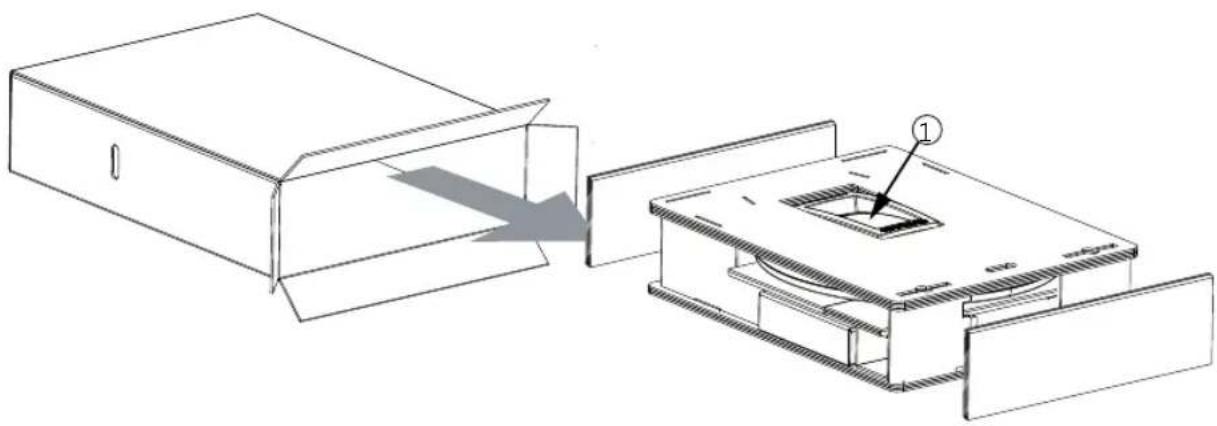
- Pull the turntable out of the packaging as shown in the illustration below.
- Remove the packing pieces from the turntable ① before you transport it to the roof of the vehicle.
- Loosen the 6 fastening screws (spanner size: 10 mm) which attach the turntable to the mounting plate.
- Carefully lift the turntable off the mounting plate and place it on the two prepared wooden supports. When doing this, make sure that the cables are not crushed where they emerge from the underside of the turntable.
5.3 Selecting the Installation Location
Essentially, the cable lengths of the MobiSet 4 CAP 920 components allow you a free choice of installation location on your caravan or motor home.
However, you should take note of the following points:
- Before installation, you should find out whether the operating manual for your vehicle permits the fitting of non-vehicle-specific parts or what requirements need to be met in order to do so.
- For direct satellite reception, there should be no obstructions between the antenna and the satellite. Therefore, make sure that the antenna is not shadowed by roof extensions such as luggage racks, air conditioning units, solar panels, etc. The problem of shadowing applies also to the selection of the parking place for your vehicle. For interference-free satellite reception, the antenna needs a projected free view to the South at an angle of between 15° and 55° (depending on location) to the horizontal.
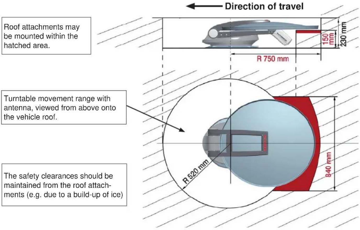
- When selecting the installation position, take into account the range of movement of the turntable (see the grey shaded area in the graphics). Within this grey area there must be no structures on the roof that would obstruct this movement (risk of collision). For safety, keep at least the required area of 1024 x 1250 mm free (for ease of installation and any subsequent dismantling).
- Choose a mounting position on the roof that is as flat as possible, depending on the location of the vehicle, since roof inclinations greater than 5° may lead to problems when searching for the satellite.
- To ensure secure adhesion, the height difference of the roof curve may not be more than 1 cm over a length of 2 m, as otherwise the gap between the roof and the mounting plate would be too great to be filled by the adhesive sealant.
- As the vehicle is constantly subjected to vibration loads during travel, the roof below the antenna unit is also subject to significant loads. Please note given the nature and capacity of your vehicle roof (see also operating manual for the vehicle) that the weight of the antenna unit is approx. 19 kg. In case of doubt, consult a qualified dealer or your vehicle's manufacturer.
Installation and connection
- The roof duct provides a watertight seal through which the three cables (2 x coax cables and 1 x power supply cable) are fed into the interior of the vehicle directly underneath the turntable. If you prefer a different method of laying the cables, they can be run from the rear of the turntable via the channel provided in the mounting plate. The cables must then be run along the roof of the vehicle in a protective cable duct and through a separate roof duct HDZ 100 (neither of them are supplied).
- The HDZ 100 roof duct is available as an accessory under part number 20410032 from specialist dealers.
Notice

Malfunction or material damage.
- Do not cut the cables.
- Protect the positive wire (red) of the power supply cable by using a 15 A blade fuse. This blade fuse
– is included in the scope of delivery,
— must be installed by a specialist.
- If the fuse is blown, it must be replaced by a fuse with the same rating (15 A). The cause of the fault must be eliminated first.
5.4 Installation steps
5.4.1 Installation of the cable gland and mounting plate
Note
If you had previously used a Kathrein HDM 140/141 jointed tripod mast or another mast with a diameter of 34 mm , you can continue using the existing through hole in the roof (if space allows).
Figure: A

Figure: B

① = adhesive
- In the centre of the intended position of the turntable, drill the opening for the cable gland with a circular cutter ( 38 mm). Deburr the hole with a round file or emery paper.
- Provisionally insert the roof gland into the drilled hole (Fig. A).
- Place the mounting plate on the roof of the vehicle, such that the centre hole is positioned centrally to the cable gland. The arrow symbol must be visible from above and point forwards in the direction of travel (Fig. B).
- Mark the positions of the ten fastening holes on the roof of the vehicle in a pitch circle.
Note
The size of the holes and the choice of fastening screws to be used (not supplied) depend on the type and thickness of the materials used in the roof structure. If the roof panelling (plastic roofs) is sufficiently strong, it is recommended that round head screws, plain washers and self-locking nuts are always used to secure the glued mounting plate.
- If the roof panel material is very thin and does not provide adequate holding power within the insulation material, through holes ( 5,5 mm) into the interior of the vehicle are required and galvanised M5 round head screws of sufficient length must be used.
Make sure that you use a sufficiently strong support that can withstand the bolt tensile forces (large plain washer or a complete reinforcing plate). - Create the holes necessary to secure the mounting plate (Fig. C).
Figure: C

*) Not included!
- In addition to the screwed connection, the mounting plate and roof duct must be bonded to the roof with adhesive and sealed. This is done using the DEKAsyl MS adhesive sealant supplied, which is ideally suited for this purpose due to its broad range of adhesion. Please note the following points:
- It is essential that you have carefully read through the safety data sheet for the DEKAsyl MS adhesive sealant and the technical data sheet in this installation manual before you start working with the DEKAsyl MS adhesive sealant!
- The prerequisite for good adhesive properties is a clean, dry and grease-free substrate. You should therefore clean the roof surface with a suitable cleaning agent within a circumference of 35cm around the drilled hole and allow the surface to dry thoroughly.
- If the surface is painted, ensure that the paint finish is sufficiently well bonded to the substrate.
- If the coat of paint is already loose or peeling, it must be removed down to a stable layer in the area to which the adhesive will bond. If you have any doubts concerning the adhesive characteristics, consult a paint and lacquer specialist, or the manufacturer of your vehicle.
Installation and connection
- The procedure for gluing the mounting plate is as follows:
Figure: D
- Before starting adhesive work, note that the optimum processing temperature of materials to be glued and the adhesive sealant is between +5 °C and +35 °C. Prepare all necessary fastening elements and tools.
- Prepare the tube of adhesive sealant in accordance with the instructions enclosed with the tube.
- Remove the roof gland (Fig. A) and apply the adhesive sealant evenly to the underside of the roof gland flange.
- Replace the roof gland in the drilled hole and press it firmly against the roof of the vehicle.
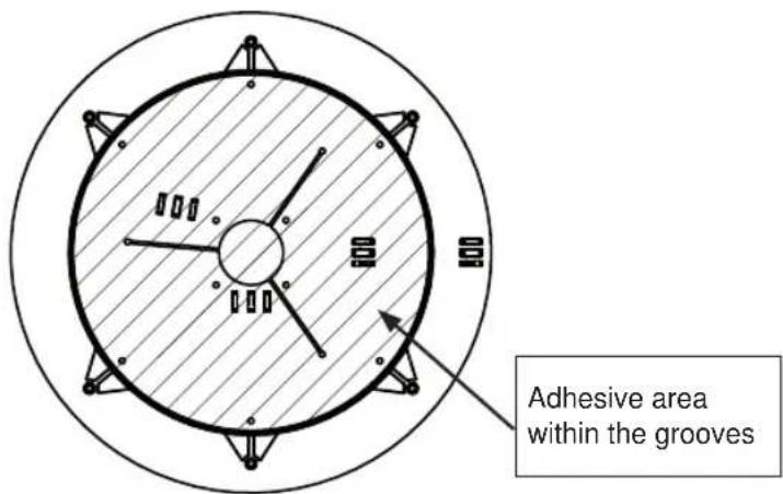
- Apply the adhesive sealant evenly to the underside of the mounting plate, completely covering the area within the circular groove (Fig. D).
This area of the vehicle roof must be completely coated with adhesive in order to achieve the necessary bonding force.
- Place the mounting plate onto the roof of the vehicle, as you did previously when marking out the drilled holes.
Make sure that the arrow on the mounting plate points forward in the direction of travel of the vehicle. The fastening holes must be perfectly aligned with the prepared holes in the roof.
- Fasten the mounting plate in place with the prepared screws, evenly tightening all ten screws across the diagonals.
Note
The adhesive sealant used is capable of filling small gaps caused by the curvature of the vehicle roof. However, you should ensure that the mounting plate is not bent by tightening the screws.
- Use a clean colourless cloth to remove any adhesive sealant that leaks out at the sides. Pay attention to the following:
\~ Do not use any cleaning agents or thinners containing solvents, as this could damage the adhesive sealant applied under the mounting plate.
\~ It is recommended to soak the cloth in acetone or MEK. Apply the cloth soaked in acetone or MEK to an inconspicuous area to make sure that it does not adversely affect or damage the surface.
\~ Use only cleansing paste and water to clean your hands.
- Secure the cable gland from inside the vehicle by tightening the ribbed nut supplied (Fig. A).
- Note that the curing of the adhesive sealant depends on the ambient temperature and the humidity. Final strength is reached only after approx. 2 days. However, this need not restrict further installation work, since the mounting plate is held in place by the tightened screws.
5.4.2 Installation of the turntable
Variant with cable gland underneath the turntable
- Lay the cables supplied with the turntable (2 × coax cables and 1 x power supply cable) into the mounting plate as indicated by the markings on the mounting plate (see Fig. E1), and feed the remaining lengths of cable through the roof gland into the interior of the motor home / caravan.
- Lift up the turntable and place it carefully on the mounting plate facing in the direction of travel (see Fig. E) (do not step on the plug connector and do not kink / crush the cables!)
The through holes on the turntable must be perfectly aligned with the threaded holes on the mounting plate.
- Allow the turntable to rest on the front edge of the mounting plate. Keep the turntable supported at an angle (see Fig. E1) and insert a suitable piece of wood underneath it.
- Now lay and connect the turntable cables in the mounting plate (as indicated on the mounting plate, see Fig. E1). Take particular care that the two master coaxial cables, marked red, are connected to each other. Initially tighten the coaxial cable plugs finger-tight, using no tools, then tighten them lightly using an open-ended 11 AF spanner.
- Now lower the turntable back on to the mounting plate, taking care whilst so doing that the cables are fed through the cable gland and are not snagged.
- Apply a little adhesive sealant to the six threaded holes in the mounting plate and screw the fastening screws into the thread. Tighten the screws to a torque of 6 Nm.
Figure: E1

Installation and connection
Figure: E2

① = sealing gasket
- To prevent water vapour from inside the vehicle reaching the turntable through the roof gland, thread the three cables through the sealing gasket supplied (see Fig. E2), close the gasket and insert it into the roof gland until it reaches the stop. Make sure that no tensile load is acting downwards on the sealing gasket as this can cause it to fall out in the course of time.
Version with external cable gland (Fig. F)
- Lay the cables supplied with the turntable (2 × coax cables and 1 x power supply cable) into the mounting plate as indicated by the markings on the mounting plate (see Fig. F), and feed the remaining lengths of cable through a cable duct*) and a cable gland¹) into the interior of the motor home / caravan.
- Lift up the turntable and place it carefully on the mounting plate facing in the direction of travel (see Fig. F2) (do not step on the plug connectors and do not kink / crush the cables!)
The through holes on the turntable must be perfectly aligned with the threaded holes on the mounting plate.
- Allow the turntable to rest on the front edge of the mounting plate. Keep the turntable supported at an angle (see Fig. F1) and insert a suitable piece of wood underneath it.
- Now lay and connect the turntable cables on the mounting plate (as indicated on the mounting plate, see also Fig. F1). Make sure that the cables are not crossed over and that they are taut so that they cannot be crushed. The two master coaxial cables, marked red, must be connected to each other. Initially tighten the coaxial cable plugs finger-tight, using no tools, then tighten them lightly using an open-ended SW 11 spanner. Do not try to pull the cables from the unit. This could damage the cables or loosen the cable connections.
- Apply a little adhesive sealant to the six threaded holes in the mounting plate and screw the fastening screws into the thread.
Tighten the screws to a torque of 6 Nm.
- Run the connecting cables through the waterproof HDZ 100 1 roof gland into the interior of the vehicle. In so doing the cables may not be crushed, kinked or damaged.
Important
The connecting cables between the turntable and the connecting/control unit may not be extended.
1) The HDZ 100 roof gland is available as an accessory under part number 20410032 from specialist dealers.
Figure: F1

Figure: F2
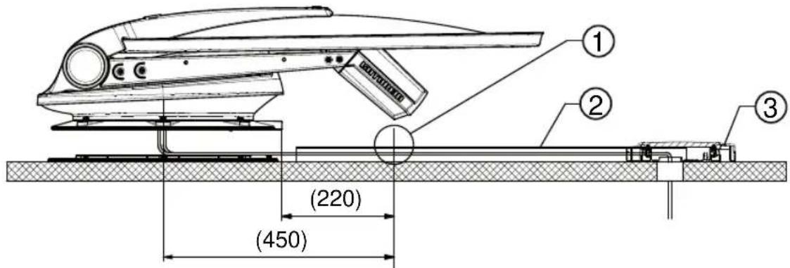
① When using a cable duct as a direct extension of the cable exit from the CAP, its height must not exceed that of the cable feed system hood, i.e. 10 mm.
② Cables laid in the cable duct
③ Roof gland HDZ 100, not included
5.5 Brief instructions for installing the turntable
Note
The sequence of pictures shown illustrates all the necessary installation steps that are required to install the turntable and the preassembled parabolic reflector on the roof of the vehicle. The other detailed instructions in this installation and operating manual must also be followed!

- Montageort festlegen.
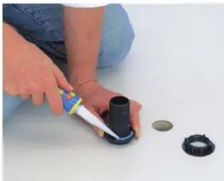
- Apply DEKAsyl MS adhesive sealant to the spigot of the roof duct. Insert the spigot into the hole and secure it from below with the knurled nut.

Important
Note when determining the installation location:
- Swing path of the unit = ∅ 162 cm.
- Drill a hole with ∅ 38 mm for the cable gland.
- Deburr any sharp edges of the hole.
See also 5.3, p.11f und 5.4, p.12ff.

- Unscrew the screws (x 6, 10 AF) from the mounting plate and remove the mounting plate.

- Place the turntable on prepared wooden supports to protect the roof of the vehicle.
-
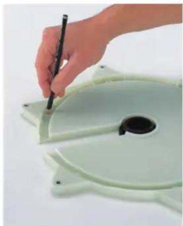
Align the mounting plate with the arrow in the direction of travel. The arrow is marked with an ① at step 8 in the illustration.
-
Mark out the six holes to secure the mounting plate.
Note
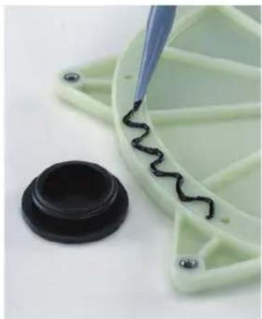
Avoid any skin contact with the adhesive sealant. For safety information on the adhesive sealant, see 11, p.32 und 12.
- Apply DEKAsyl MS adhesive sealant in a wavy line between the two grooves and spread it with a spatula or similar.
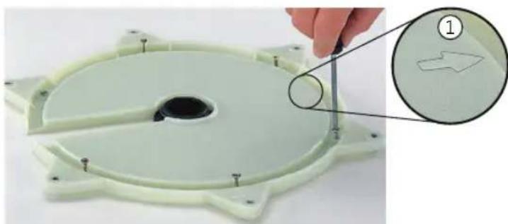
- Place the mounting plate on the roof gland and secure it with the appropriate screws (choose screws according to thickness/structure of roof).

- Screw the turntable onto the mounting plate using the torque wrench.
Important

Comply with the tightening torque of 6 Nm.
- Make the electrical connections.
- Connect the receiver.
- Connect the turntable to the battery.

Warning
Danger of injury. The antenna must always be lowered into the horizontal position (park position) while driving. Comply with the maximum speed of 130 km/h for the vehicle.
5.6 Installation of the UFS 946/CI+
5.6.1 Selection of a suitable installation location
Note
When choosing the installation location, bear in mind that the rear of the unit should always be accessible. The UFS 946/CI+ is equipped with a power saving circuit and a separate infrared transmitter, which means that the unit does not need to be placed where it is visible. You can therefore fit the UFS 946/CI+ out of sight in any location, e.g. on cupboard walls, side walls or the base of storage compartments.
The four screw sockets provided (see diagram on the next page) allow you to install the receiver not only resting on a shelf but also to fix it there or in other positions.
In addition, the following points should be taken into account:
- The wall thickness at the installation location must be at least 15 mm, as otherwise the screws will break through on the other side or damage the surface
- Ensure that the cupboard or storage compartment in which the unit is housed is adequately ventilated, to prevent a build up of heat. Carpet-covered walls are unsuitable for installation
- Take care when tightening the screws not to damage any cables etc., behind or in the wall
- The receiver is designed for installation in exclusively dry, interior locations. The installation location must be protected against moisture
- The cable lengths must be taken into account when choosing the installation location
- The connecting cables must be provided with strain reliefs
Ventilation
The heat generated within the receiver can be dissipated from the following sides of the casing: Bottom, left, right and top. When selecting the installation location, make sure that these sides are not obstructed or covered. If the unit is operated continuously with insufficient ventilation, this can negatively affect the length of its working life!
Maintain a clearance of at least 20 cm above or below the unit, 2 cm to either side and 5 cm behind it, to allow unobstructed dissipation of the heat generated.

Important

Danger of damage. The unit monitors its own temperature in operation. Premature failure of the unit due to continuous operation at temperatures higher than the recommended operating temperature as a result of insufficient ventilation does not constitute grounds for a claim under warranty / guarantee.
Connections and fusing of the unit
All connection cables for connection to the receiver (including the infra-red sensor) are connected at the rear of the unit (see also “Connection example” in this section). When selecting the installation location, allow sufficient clearance at the rear of the unit for these cables and their plugs.
On the left hand side of the receiver viewed from the front there is a fuse inserted from the outside. This fuse (for the type, see the section “Important Information” in the receiver operating manual) should be accessible even after the unit has been installed, so that it can easily be exchanged if required.
5.6.2 Preparations
Attaching the infrared sensor
You can attach the infra-red sensor directly to the unit; or if the receiver is installed in a concealed location, you should position the infra-red sensor where it can be clearly seen by the remote control unit.
The infrared sensor is installed with the aid of the supplied adhesive strip on the flat underside.

5.6.3 Important instructions for installation

Warning
Danger to life from electric shock. Do not use the wood screws that had been included with the receiver to mount the receiver onto a TV set or other electrical device. The wood screws could make contact with electrically live parts.
Important

Under no circumstances use countersunk-head screws for installation (see the diagram on the right), since these can damage the screw sockets on the receiver. Wherever possible, use the wood screws supplied with the receiver.
Before installing the receiver so that it is attached to another piece of equipment (such as a TV set), check with the manufacturer of that equipment or by reference to the documentation supplied with it whether this is permissible, and if so what fittings (screws, etc.) you need / can use for this. The temperature rise of each of the units in operation (receiver/TV set) can in some circumstances affect the other unit.

Installation and connection
5.6.4 Suspended installation
Remove the wood screws supplied from their transport attachment on the top of the respective mounting piece (2 pieces).
Place the two mounting pieces on your receiver as shown in Figures 1–3. During the process the following should be taken into account:
- Left (L) and Right (R) markings (see arrows Figure 2)
- The teeth on the underside of the mounting pieces must be inserted in the first and last row of the ventilation slots on the top of the receiver (see the arrows Fig. 1)


Now hold the receiver, with the installation kit attached, at the installation location. Screw in the wood screws supplied through the smaller holes in the screw attachment area (44). Wherever possible, use the wood screws supplied. If these are unsuitable, other screws of adequate size and strength can be used. Under no circumstances however use countersunk wood screws, since these can damage the attachment area (see Fig. 5).
x)
Screw attachment
Left
④

Right
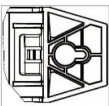
Then screw all four screws fully home, so that the installation kit is no longer able to come free.

For subsequent disassembly it is sufficient to undo all screws one turn each and to push the receiver to the right (suspended) or left (on top) to release it.
5.6.5 Installation on a fixed flat surface
So as to prevent the receiver slipping or falling, the installation kit can also be attached to the underside of the receiver. Assembly is the same as for suspended installation, except that the kit is attached to the underside of the receiver.

5.6.6 Laying the cables and connecting the turntable
- Lay the master coaxial cable (marked red) to the first receiver and the second coaxial cable to the second receiver. If you are not using a second receiver, we recommend that you lay the second coaxial cable in any case, so that it is available should you ever need it.
- Lay the turntable power supply cable (3-pin plug) to the battery.
Important

Avoid laying the cables across sharp edges and protect the cables against possible chafing point.
- Connect the master coaxial cable (coming from the turntable) to the "IF IN" F socket at the rear of the first receiver.
- Place the infrared sensor for the receiver close to or directly on top of the TV set and lay the cable to the receiver. Connect the 6-pin Western connector at the rear to the socket marked "IR REMOTE IN" (see also 5.6.9, p.25).
- Connect the receiver and the TV set with the HDMI cable Plug the HDMI cable into each set at the "HDMI" socket.
- Make sure that the 15 A blade fuse on the positive wire (red) of the power supply cable was installed by a specialist.
1) The HDMI cable is included with the receiver.
5.6.7 Connection of the receivers
Important

The receiver may not be connected to any other power supply than 12 V. The receiver's earth connection must be connected to the negative pole of the motor home or caravan battery.
Isolate the on-board power supply (master switch "off" or disconnect the positive pole of the on-board power supply battery) before commencing the following work:
- Connect the power cable supplied (depending on the power supply available in your motor home or caravan, either a 12 V supply or a 230 V supply via a power supply unit) to the "12V seek" on the receiver.
- Make sure that the “inline” integrated fuse (5 A) of the cable is fully plugged in and is intact. If the fuse blows, the source of the fault must first be eliminated. The fuse may only ever be replaced by a fuse with the same rating (5 A).

Danger of cable fires. Never bypass the fuses in the cable and in the receiver
- At the connecting point for the power cable, the voltage must not fall below 11.5 V even with a load of 12 A. Otherwise optimum functioning can no longer be guaranteed.
- Connect the power cable to the respective socket in your motor home or caravan (12 V or 230 V).
Only for connection in a motor home, not in a caravan!
- The third, green connecting cable, marked "IGNITION" allows you the option of connection to a circuit in the vehicle that is activated when the ignition key is turned and then carries a continuous 12 V supply. This type of connection ensures that when the engine is started the antenna is automatically lowered into the park position (the receiver does not need to be turned on).
Note that the antenna can then be lowered only when the power supply is present in addition to the ignition signal!
- Check the connections before you re-connect the on-board power supply.
- For commissioning and more detailed information on additional operator functions, please consult the operation section of the separate operating manual for the receiver.
5.6.8 Functional instructions for connection to the on-board power supply
Under certain circumstances, problems can arise when the units are connected to different connecting sockets or circuits/earth potentials. If no others are available, it is recommended that you connect the connecting sockets for receiver and TV set to the same cable, as shown in Fig. G. The power rating of the circuit used must be checked with respect to the intended application.
Further information on operating the UFS 946/CI+ receiver can be found in the operating manual supplied with the unit.
5.6.9 Connection example for 12 V battery connection

Important
For operation with two batteries, it is necessary to ensure that the ignition signal earth has the same potential as the power supply battery earth for the turntable. Non-compliance means that the automatic lowering function will not work! Ensure the cable po correct!
arity is

① Important
To enable the GPS data to be read and the antenna to be lowered automatically into the park position, connect the green wire to the ignition and the red and the black wire to the vehicle battery.
6 Reception range / footprint
The footprint is the reception area on the earth that a satellite covers with its transmission beam (spot), within which satellite reception is possible. The transmission power is at its greatest in the centre of this spot – it becomes progressively weaker moving outwards.
The satellites broadcast the various channel packages in different footprints. Normally all program packages can be received within the spots. While reception is possible in principle at the edge zones, the quality depends on various factors such as the diameter of the satellite antenna and the weather conditions.
Fig. A shows the spots of the most commonly used satellites for the antenna of the CAP 920.
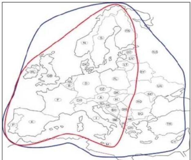
Fig. A: Spot ASTRA 19.2° East (inner line) and EUTELSAT Hotbird 13° East (outer line)
7 Dismantling for servicing
If repairs to the system or individual components are necessary, contact your specialist dealer or our service centre (see below for the address).

Never open the turntable yourself!!
7.1 Removing

Do not cut the cables! At the cable junction provided, disconnect the cables projecting from the turntable from the two cables laid within the interior of the vehicle (unplug the plug).
Note
Before exchanging the UFS 946/CI+ you must first move the turntable to the park position.
- The cables laid within the vehicle can remain there.
- Unscrew the six M6 screws securing the turntable to the mounting plate.
- Place two wooden supports on the vehicle roof for protection.
- Then place the turntable on the prepared wooden supports.
- To ship the turntable, use the original packaging which you have saved.
- Seal the opening in the vehicle roof appropriately to protect against the ingress of moisture.
- If an HDZ 100 roof gland has been fitted and the equipment is then removed, the cable glands that are no longer used should be sealed with the integral plugs. The enclosure is then watertight once again.
7.2 Address of the service centre
Main factory repair centre Regional repair centre
83224 Grassau, Germany
Tel.: 08641 6998427
Fax: 08641 6998429
E-mail: service@css-grassau.de
The polarisations setting is required to compensate for the so-called skew. The skew is the discrepancy between the vertical polarisation of the received signal from the geographical verticals. For optimal reception the LNB must be installed before the satellite disk, inclined by the skew angle.
The CAP 920 calculates the skew angle on the basis of the GPS data and inclines the LNB fully automatically. The prerequisite for this is that valid GPS data are available.
9 Manual lowering to park position
Important
- If a defect arises in the electronic controls, after some disassembly work the satellite dish can be returned to the park position (horizontal position) manually. Following this, however, recalibration by an authorised workshop is always necessary.
- Driving to the nearest workshop at a moderate speed with the antenna extended and taking into account the increase (+79 cm) in the vehicle height is an option and is preferable to manual lowering.
- Users unfamiliar with the necessary repair work are urged not to attempt to lower the antenna manually into the park position themselves. They should contact a technician or engineer. They may find a suitable person on the campsite.
• Always follow the safety instructions listed below.
9.1 Safety instructions

Caution
Danger of injury and even death from
- roof collapsing,
- falling,
– falling parts in the motor home,
– movements of the turntable.


Please note in particular that:
- The antenna and connected units are disconnected from the power,
- The person carrying out the repair does not suffer from vertigo and can move around safely on the roof of the caravan or motor home,
- The person carrying out the repairs is wearing sturdy non-slip shoes,
- The person carrying out the repairs has a secure position to stand and hold on while working,
- The roof and the climbing equipment used (e.g. ladder) are dry, clean and non-slip,
- The roof can withstand the weight of the person carrying out the repairs,
- Do not hold onto the antenna, as the rocker can come free without warning during dismantling,
- Nobody should be underneath the antenna inside the caravan / motor home during dismantling / installation.
9.2 Manual Retraction
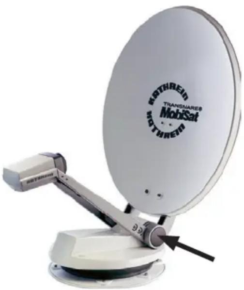
- In the centre of the axis (arrowed) there is a plastic cap on both sides. Lever these off with a narrow flat-bladed screw-driver.
⇒ You can see the following hexagon socket head cap screws: 1x M10 (WAF 8 mm) per side, 2x M6 (WAF 5 mm) on one side.
- Remove the 4 hexagon socket head cap screws.
⇒ You can see another thread on both sides.
3.
Notice
- Screw in each M12 screw only as far as to free the rocker from the engagement on the tapered shaft!
- Secure and support the antenna to prevent it from tipping over. The connection to the rocker can suddenly come loose when you screw in the M12 screw. It is then no longer connected to the turntable!
Screw an M12 screw (minimum length: 40 mm) into each of the other threads using a 19 mm socket wrench. Screwing in the M12 screw pushes the rocker off the taper seating on the tapered shaft and releases the engagement.
- Tilt the antenna into the park position (horizontal position).
- Remove the M12 screws. This allows the rocker to re-engage on the tapered shaft.
- Replace the 4 hexagon socket head cap screws and tighten them firmly (1x M10 per side, 2x M6 on one side).
- Replace the plastic caps.
Important
Loosening the rocker from the taper shaft causes the rocker zero point position to be lost. The defect must be eliminated and the rocker recalibrated by an authorised dealer!
- Consult an authorised dealer.
10 Technical Specifications
| Type Unit CAP 920 | ||
| Order no. 20310029 | ||
| Diameter parabolic reflector approx. cm 75 | ||
| LNB 2 switchable outputs: | V/H (14/18 V)Low/High (0/22 kHz) | |
| Supply voltage LNB V Vertical: 11.5 – 14 | Horizontal: 16 – 19 | |
| Input frequency GHz 10.70 – 12.75 | ||
| Output frequency MHz 950 – 1950 / 1100 – 2150 | ||
| Oscillator frequency (L. O.) GHz 9.75/10.60 | ||
| Performance at 11.3/12.5 GHz | dB/K | 16.9/17.9 |
| Power supply (vehicle battery) | V | 11.5 – 13.8 |
| Power consumption from the 12 V vehicle electrical systemInrush currentSatellite searchTV receptionStandby | A | Typ. 10, max. 12Typ. 3Typ. 1.2Typ. 0.024 |
| Current consumption from the receiver | mA | Typ. 200 |
| Setting rangeElevationAzimuthSkew | ° | 3 – 67390±45 |
| Weight of the turntable with parabolic reflector | kg | 18.9 |
| Packing unit/weight | Units/kg | 1/32.5 |
| Ignition signal | 12 – 24 V | |
| Search time for first satellite | Typ. 10 – 120 s | |
| Search time for further satellites | Typ. 2 – 30 s | |
| Startup time LSM1) | 5 – 30 s | |
1) LSM = Last Satellite Memory
Dimensions

Printing date 29.05.2015 Revision: 29.05.2015 Version number 13
SECTION 1: Identification of the substance/mixture and of the company/undertaking
· 1.1 Product identifier
. Trade name: Dekasyl MS-5
1.2 Relevant identified uses of the substance or mixture and uses advised against No further relevant information available.
- Application of the substance / the mixture
Sealant
Glue/ Sising agent
· 1.3 Details of the supplier of the safety data sheet
Manufacturer/Supplier:
Dekalin, brand of Diffutherm B.V.
Smaragdweg 50
NL-5527 LB Hapert
Tel: +31 497 551 080
Fax: +31 497 551 088
E-mail: info@dekalin.nl
· Further information obtainable from: Product safety Department
- 1.4 Emergency telephone number: National Poisons Information Center (NVIC) TEL:+31 (0)30-2748888 Only for the purpose of informing medical personnel in cases of acute intoxications
SECTION 2: Hazards identification
· 2.1 Classification of the substance or mixture
· Classification according to Regulation (EC) No 1272/2008
The product is not classified according to the CLP regulation.
- Classification according to Directive 67/548/EEC or Directive 1999/45/EC Not applicable.
- Information concerning particular hazards for human and environment:
The product does not have to be labelled due to the calculation procedure of the "General Classification guideline for preparations of the EU" in the latest valid version.
- Classification system:
The classification is according to the latest editions of the EU-lists, and extended by company and literature data.
- 2.2 Label elements - Labelling according to Regulation (EC) No 1272/2008 Void
.Hazard pictograms Void
. Signal word Void
.Hazard statements Void
. Additional information:
Safety data sheet available on request.
.2.3 Other hazards
· Results of PBT and vPvB assessment
· PBT: Not applicable.
·vPvB: Not applicable.
SECTION 3: Composition/information on ingredients
.3.2 Chemical characterisation: Mixtures
.Description: Mixture of substances listed below with additions.
. Dangerous components:
(Contd. on page 2)
GB
Printing date 29.05.2015 Revision: 29.05.2015 Version number 13
Trade name: Dekasyl MS-5
| (Contd. of page 1) | ||
| EC number: 907-495-0Reg.nr.: 01-2119545465-35 | Reaction mass of Octadecanamide, 12-hydroxy-N-[2-[(1-oxodecyl)amino]ethyl]- and N,N'-ethane-1,2-diylbis(12-hydroxyoctadecan-1-amide) and Decanamide, N,N'-1,2-ethanediylbis-R52Aquatic Chronic 3, H412 | 1-<5% |
| CAS: 2768-02-7EINECS: 220-449-8 | TrimethoxyvinylsilanXn R20R10Flam. Liq. 3, H226; Acute Tox. 4, H332 | 1-<5% |
| CAS: 25973-55-1EINECS: 247-384-8 | phenol, 2-(2h-benzotriazol-2-yl)-4,6-bis(1,1-dimethylpropyl)Xn R48/22R53STOT RE 2, H373; Aquatic Chronic 3, H412 | <1% |
.SVHC
25973-55-1 phenol, 2-(2h-benzotriazol-2-yl)-4,6-bis(1,1-dimethylpropyl)
Additional information: For the wording of the listed risk phrases refer to section 16.
SECTION 4: First aid measures
.4.1 Description of first aid measures
· General information: No special measures required.
- After inhalation: Supply fresh air; consult doctor in case of complaints.
. After skin contact:
Immediately wash with water and soap and rinse thoroughly. If skin irritation continues, consult a doctor.
· After eye contact:
Rinse opened eye for several minutes under running water. If symptoms persist, consult a doctor.
· After swallowing: Wash out mouth with water. Contact a physician.
4.2 Most important symptoms and effects, both acute and delayed No further relevant information available.
4.3 Indication of any immediate medical attention and special treatment needed
No further relevant information available.
SECTION 5: Firefighting measures
.5.1 Extinguishing media
·Suitable extinguishing agents:
CO2, powder or water spray. Fight larger fires with water spray or alcohol resistant foam.
- 5.2 Special hazards arising from the substance or mixture
In case of fire, the following can be released: Carbon monoxide (CO)
· 5.3 Advice for firefighters
· Protective equipment: Mount respiratory protective device.
· Additional information Cool endangered receptacles with water spray.
SECTION 6: Accidental release measures
- 6.1 Personal precautions, protective equipment and emergency procedures Not required.
- 6.2 Environmental precautions: Do not allow to enter sewers/ surface or ground water.
· 6.3 Methods and material for containment and cleaning up:
Absorb with liquid-binding material (sand, diatomite, acid binders, universal binders, sawdust).
· 6.4 Reference to other sections
No dangerous substances are released.
See Section 7 for information on safe handling.
See Section 8 for information on personal protection equipment.
(Contd. on page 3)
GB
Printing date 29.05.2015 Revision: 29.05.2015 Version number 13
Trade name: Dekasyl MS-5
See Section 13 for disposal information.
(Contd. of page 2)
SECTION 7: Handling and storage
.7.1 Precautions for safe handling
No special measures required.
Use only in well ventilated areas.
· Information about fire - and explosion protection: No special measures required.
- 7.2 Conditions for safe storage, including any incompatibilities
Storage:
- Requirements to be met by storerooms and receptacles: No special requirements.
· Information about storage in one common storage facility: Not required.
· Further information about storage conditions: None.
- 7.3 Specific end use(s) No further relevant information available.
SECTION 8: Exposure controls/personal protection
· Additional information about design of technical facilities: No further data; see item 7.
- 8.1 Control parameters
· Ingredients with limit values that require monitoring at the workplace:
The product does not contain any relevant quantities of materials with critical values that have to be monitored at the workplace.
CAS No. Designation of material % Type Value Unit Not required.
· Additional information: The lists valid during the making were used as basis.
-8.2 Exposure controls
· Personal protective equipment:
· General protective and hygienic measures:
The usual precautionary measures are to be adhered to when handling chemicals.
. Respiratory protection: Not required.
• Protection of hands: Protective gloves and protective skin cream
. Material of gloves
PVC or PE gloves
The selection of the suitable gloves does not only depend on the material, but also on further marks of quality and varies from manufacturer to manufacturer. As the product is a preparation of several substances, the resistance of the glove material can not be calculated in advance and has therefore to be checked prior to the application.
Recommended thickness of the material: ≥ 0,12 mm
- Penetration time of glove material
480 min.
The exact break trough time has to be found out by the manufacturer of the protective gloves and has to be observed.
· Eye protection: Goggles recommended during refilling
SECTION 9: Physical and chemical properties
.9.1 Information on basic physical and chemical properties
· General Information
· Appearance:
Form:
Colour:
· Odour:
· Odour threshold:
Pasty
According to product specification
Characteristic
Not determined.
(Contd. on page 4)
GB
Printing date 29.05.2015 Revision: 29.05.2015 Version number 13
Trade name: Dekasyl MS-5
| ·pH-value: | Not determined. |
| ·Change in conditionMelting point/Melting range:Boiling point/Boiling range: | Undetermined.Undetermined. |
| ·Flash point: | Not applicable. |
| ·Flammability (solid, gaseous): | Not applicable. |
| ·Ignition temperature: | |
| Decomposition temperature: | Not determined. |
| ·Self-igniting: | Product is not selfigniting. |
| ·Danger of explosion: | Product does not present an explosion hazard. |
| ·Explosion limits:Lower:Upper: | Not determined.Not determined. |
| ·Vapour pressure: | Not determined. |
| ·Density At 20 °C:Relative densityVapour densityEvaporation rate | 1.5 g/cm3(DIN 51757)Not determined.Not determined.Not determined. |
| ·Solubility in / Miscibility with water: | Not miscible or difficult to mix. |
| ·Partition coefficient (n-octanol/water): | Not determined. |
| ·Viscosity:Dynamic:Kinematic: | Not determined.Not determined. |
| ·Solvent content:Organic solvents: | 0.0 % |
| Solids content:9.2 Other informationVOC (EU):VOCV: | 97.0 % (DIN 53216)No further relevant information available.0.00 %0.00 % |
SECTION 10: Stability and reactivity
· 10.1 Reactivity
· 10.2 Chemical stability
· Thermal decomposition / conditions to be avoided: No decomposition if used according to specifications.
· 10.3 Possibility of hazardous reactions No dangerous reactions known.
· 10.4 Conditions to avoid No further relevant information available.
· 10.5 Incompatible materials: No further relevant information available.
SECTION 11: Toxicological information
· 11.1 Information on toxicological effects
· Acute toxicity:
· LD/LC50 values relevant for classification:
ATE (Acute Toxicity Estimates)
Inhalative LC50/4 h 368 mg/l
(Contd. on page 5)
GB
Printing date 29.05.2015 Revision: 29.05.2015 Version number 13
Trade name: Dekasyl MS-5
(Contd. of page 4)
- Primary irritant effect:
· on the skin: No irritant effect.
· on the eye: No irritating effect.
· Sensitisation: No sensitising effects known.
· Additional toxicological information:
The product is not subject to classification according to the calculation method of the General EU Classification Guidelines for Preparations as issued in the latest version. When used and handled according to specifications, the product does not have any harmful effects to our experience and the information provided to us.
SECTION 12: Ecological information
· 12.1 Toxicity
· Aquatic toxicity: No further relevant information available.
· 12.2 Persistence and degradability No further relevant information available.
· 12.3 Bioaccumulative potential No further relevant information available.
· 12.4 Mobility in soil No further relevant information available.
· Additional ecological information:
· General notes:
Water hazard class 1 (German Regulation) (Self-assessment): slightly hazardous for water
Do not allow undiluted product or large quantities of it to reach ground water, water course or sewage system.
.12.5 Results of PBT and vPvB assessment
.PBT: Not applicable.
.vPvB: Not applicable.
.12.6 Other adverse effects No further relevant information available.
SECTION 13: Disposal considerations
· 13.1 Waste treatment methods
- Recommendation Smaller quantities can be disposed of with household waste.
. European waste catalogue
| 08 00 00 | WASTES FROM THE MANUFACTURE, FORMULATION, SUPPLY AND USE (MFSU) OF COATINGS (PAINTS, VARNISHES AND VITREOUS ENAMELS), ADHESIVES, SEALANTS AND PRINTING INKS |
| 08 04 00 | wastes from MFSU of adhesives and sealants (including waterproofing products) |
| 08 04 10 | waste adhesives and sealants other than those mentioned in 08 04 09 |
- Uncleaned packaging:
- Recommendation: Disposal must be made according to official regulations.
SECTION 14: Transport information
.14.1 UN-Number
· ADR, ADN, IMDG, IATA Void
· 14.2 UN proper shipping name
· ADR, ADN, IMDG, IATA Void
· 14.3 Transport hazard class(es)
| · ADR, ADN, IMDG, IATA | |
| · Class | Void |
· 14.4 Packing group
- ADR, IMDG, IATA Void
(Contd. on page 6)
GB
Printing date 29.05.2015 Revision: 29.05.2015 Version number 13
Trade name: Dekasyl MS-5
| (Contd. of page 5) | |
| ·14.5 Environmental hazards:·Marine pollutant: | No |
| ·14.6 Special precautions for user | Not applicable. |
| ·14.7 Transport in bulk according to Annex II of MARPOL73/78 and the IBC Code | Not applicable. |
| ·Transport/Additional information: | Not dangerous according to the above specifications. Transport classification ADR/IMGD is based on packaging >30ltr(IMDG), <450ltr(ADR). For other packaging units different classification can apply. |
| ·UN "Model Regulation": | - |
SECTION 15: Regulatory information
· 15.1 Safety, health and environmental regulations/legislation specific for the substance or mixture
· Labelling according to Regulation (EC) No 1272/2008 Void
· Hazard pictograms Void
· Signal word Void
· Hazard statements Void
· National regulations:
. Waterhazard class: Water hazard class 1 (Self-assessment): slightly hazardous for water.
. Other regulations, limitations and prohibitive regulations
· Substances of very high concern (SVHC) according to REACH, Article 57
25973-55-1 phenol, 2-(2h-benzotriazol-2-yl)-4,6-bis(1,1-dimethylpropyl)
· 15.2 Chemical safety assessment: A Chemical Safety Assessment has not been carried out.
SECTION 16: Other information
This information is based on our present knowledge. However, this shall not constitute a guarantee for any specific product features and shall not establish a legally valid contractual relationship.
. Relevant phrases
H226 Flammable liquid and vapour.
H332 Harmful if inhaled.
H373 May cause damage to organs through prolonged or repeated exposure.
H412 Harmful to aquatic life with long lasting effects.
R10 Flammable.
R20 Harmful by inhalation.
R48/22 Harmful: danger of serious damage to health by prolonged exposure if swallowed.
R52 Harmful to aquatic organisms.
R53 May cause long-term adverse effects in the aquatic environment.
· Department issuing MSDS: Product safety department.
- Contact: info@dekalin.nl
·Abbreviations and acronyms:
International Transport of Dangerous Goods by Rail)
ICAO: International Civil Aviation Organisation
ADR: Accord européen sur le transport des marchandises dangereuses par Route (European Agreement concerning the International Carriage of Dangerous Goods by Road)
IMDG: International Maritime Code for Dangerous Goods
IATA: International Air Transport Association
GHS: Globally Harmonised System of Classification and Labelling of Chemicals
EINECS: European Inventory of Existing Commercial Chemical Substances
(Contd. on page 7)
GB
Printing date 29.05.2015 Revision: 29.05.2015 Version number 13
Trade name: Dekasyl MS-5
(Contd. of page 6)
ELINCS: European List of Notified Chemical Substances CAS: Chemical Abstracts Service (division of the American Chemical Society) LC50: Lethal concentration, 50 percent LD50: Lethal dose, 50 percent Flam. Liq. 3: Flammable liquids, Hazard Category 3 Acute Tox. 4: Acute toxicity, Hazard Category 4 STOT RE 2: Specific target organ toxicity - Repeated exposure, Hazard Category 2 Aquatic Chronic 3: Hazardous to the aquatic environment - Chronic Hazard, Category 3
GB
DEKASYL MS-5 HIGH TACK ADHESIVE & SEALANT
PRODUCT
Dekasyl MS-5 is a MS Polymer based adhesive with a high green strength and is suitable for making elastic constructive joints. Due to its high green strength clamping times can often be reduced or clamps are not needed anymore. Dekasyl MS-5 can also be used as sealant, if similar material (similar stiffnesses) are joined together, or if mechanical fastening methods are used.
APPLICATIONS
- Elastic bondings and sealings in e.g. bus-, train-, caravan-, camper and truck construction.
- Bonding of windows in e.g. busses and trains.
- Bonding of corner profiles of aluminium or polyester on trailers.
- Bonding of polyester parts on metal frames.
FEATURES
• Solvent-, isocyanate- and PVC free.
• Very good UV-resistance and ageing properties.
• In general good adhesion on several substrates without the use of a primer.
- Permanent elastic within temperatures from -40°C till +120°C .
- Neutral, odourless and fast curing.
- Paintable after skin forming (wet on wet); this will in general not influence the curing speed.
- Paint compatible with most industrial paint- or lacquer systems, both alkyd resin and dispersion based (due to the large scale of different types of industrial paints a paint compatibility test is recommended!)
ADHESION
In general Dekasyl MS-5 adheres well without primer on clean, dry, dust- and grease free substrates of aluminium, stainless steel, galvanised steel, zinc, copper, brass, powder coated metal, most lacquered metal surfaces, glass, PVC, polyester (GRP), painted and lacquered wood, etc. No adhesion on untreated polyethylene, polypropylene and teflon. In those cases where due to great thermal or physical loads, especially under wet conditions, high adhesion demands are needed, the use of an adhesion promotor is recommended. For not mentioned substrates and additional information consult Dekalin
METHOD OF USE
Dekasyl MS-5 can easily be extruded with a hand- or air pressure gun at temperatures between +5°C and 35°C. In sealing applications Dekasyl MS-5 should be tooled or smoothened within 12 minutes (at 20°C/50%R.H.) with a spatula or putty knife, occasionally moistened with a mild soap solution. Avoid soap solution penetrating between joint sides and sealant, because this will create loss of adhesion. In bonding applications the substrates have to be assembled within 15 minutes (at 20°C/50%R.H.) after applying Dekasyl MS-5. The higher the temperature, the shorter the open time will be! In general an adhesive thickness of 2 mm is recommended if similar materials (similar stiffnesses) are bonded. The larger the difference in thermal expansion is, the thicker the adhesive bead should be. For more details Dekalin should be consulted. At a temperature of 20°C and a relative humidity of 50% Dekasyl MS-5 can be painted with the most industrial paints already 10 minutes after application. Best adhesion of paint coats is generally obtained if painted within 4 hours after applying Dekasyl MS-5. Cleaning tools or removing uncured residue of Dekasyl MS-2 can be done with a clean colourless cloth, wetted with e.g. acetone or MEK. It is recommended to make a trial first to check possible attack of the substrate by these cleaners.

DEKALIN
HIGH QUALITY PRODUCTS
FOR MOTORHOME, CARAVAN AND TRAILER TENT
TECHNICAL DATA SHEET
TECHNICAL DATA
Basic material : MS Polymer
Curing method : moisture
Specific density (20°C) : ca. 1.4 kg/liter
Skin forming time (20°C/50% R.H.) : ca. 12 min.
Open time (20°C/50%R.H.) : < 15 min.
Curing speed after 24 hrs (20°C/50%R.H.) : ca. 4 mm
Shore A hardness (DIN 53505) : ca. 55
Volume change (DIN 52451) : < 3%
Green strength (Physica Rheometer MC100) : ca. 700 Pa
(max. load which can be applied per m2 uncured adhesive without sagging)
Tensile stress (100%) (DIN 53504/ISO 37) : ca. 1.7 MPa
Tensile stress at break (DIN 53504/ISO 37) : ca. 2.8 MPa
Elongation at break (DIN 53504/ISO 37) : ca. 210%
Shear stress (DIN 53283/ASTM D1002) : ca. 2.5 MPa
(Alu-Alu; adh. thickness 2mm; test speed 50 mm/min.)
Tear propagation (DIN 53515/ISO 34) : ca. 14 N/mm
(Type C, test speed 500 mm/min.)
Solvent percentage : 0%
Isocyanate percentage : 0%
Temperature resistance
Temperature resistance (max. 20 minutes)
Application temperature
UV- and weather resistance
Colours (standard)
Packaging
:-40°C till +120°C
: +180°C
: +5°C till +35°C
: excellent
: white, black
: 290 ml cartridges, 600 ml bags, other packaging on request.
STORAGE STABILITY
Dekasyl MS-5 may be stored for 12 months in a closed (unopened) packaging in a dry place at temperatures between +5°C and +30°C (cartridges 18 months).
SAFETY PRECAUTIONS
No specific safety precautions required. Consult safety data sheet.
TRANSPORT CLASSIFICATION
Not applicable.
©Dekalin November, 2013
Dekalin, brand of Diffutherm B.V.
Smaragdweg 50
NL-5527 LB Hapert
Tel. +31 (0)497 551 080
Fax +31 (0)497 551 088
E-mail: info@dekalin.nl
Internet: www.dekalin.com
All figures, recommendations and safety precautions are based on thorough investigations and our actual experience and are without engagement. Although the documentation has been set up with most carefulness, we do not accept any responsibility for mistakes, inaccuracies or printer's errors. We reserve the right to adjust the product, whenever we feel necessary. Because the design, the quality of the substrate and the conditions during application fall beyond our control, no responsibility for executed works can be accepted on the basis of this documentation. We therefore recommend to carry out own tests on the spot. All our deliveries are subject to the General Terms and Conditions of Sale and Purchase of Difuthem B.V.

ISO 9001 ISO 14001
The operating manual part for the
CAP 920
starts from this page
If, despite studying these operating instructions, you still have questions about getting started with the unit or using it correctly, or if unexpected problems occur, please contact your specialist dealer.
The Kathrein Technical Customer Support is also at your disposal. Tel.: 08031/184/-700
Note
The EPG data for the currently selected channel is updated automatically in the background while you are watching a TV channel. You can also have the EPG data updated automatically by the receiver. Set thus under "Main menu", "Settings", "User Defined Settings", "EPG Setup" and "EPG Grabbing Time". The receiver switches itself on at the selected time and updates the EPG data. After updating the data, the receiver switches back to standby mode.
13 Important information for CAP 920 before setup

Warning
In the following operating manual we assume that the UFS 946/CI+ and the turntable have been properly installed and connected, as described in the installation and operating manuals. If you have not yet done so, read the safety instructions at the beginning of the UFS 946/CI+ operating manual and follow them when handling the UFS 946/CI+ and the turntable!

Important
Risk of damage to property.
- Before setting up your satellite system, make sure that the location allows a free view to the satellite positions to the South and is not shadowed by trees or other obstructions. This will save you time and effort.
- So as to avoid overheating the turntable motors, do not operate the motors continuously for longer than 20 minutes. None of the search procedures initiated by the CAP 920 will require as much as 20 minutes operation. Only repeated unsuccessful search procedures or manual overrides by the user can cause this limit to be exceeded.
- As soon as the ignition signal is no longer present at the turntable, if the receiver is switched on the turntable will be supplied with a +12 V power supply and may automatically move to the last known satellite position. Therefore switch your receiver on only if you wish to use your CAP 920.

Remote control
All settings on the UFS 946/Cl+ are made using the remote control.
14 First installation

Warning
- Before using your unit for the first time, read the "Safety Instructions – Important Information" and "Installation and Connection" sections.
- You will find a sample configuration for a motor home in the Section "Installation and connection", "Connection Example".
- Do not connect the unit to the power supply until all installation work has been properly carried out.
- The guidance given in the "First Installation" section assumes that the receiver has been properly connected, as per the "Safety Instructions – Important Information" and "Installation and Connection" sections.
First switch your TV set on and select the AV or video/HDMI input that you used to connect the receiver to your TV set. Switch on your receiver at the power switch on the rear of the unit. The following on-screen display appears:

Also note the bars at the bottom of the on-screen display! This provides information on what to do next.
Select the menu language you want using the ▲▼ buttons. Available options: German, English, French, Italian, Spanish, Czech, Dutch, Polish Turkish and Russian.
Press the 📄 (green) button to move to the next menu.
Note
If you are unsure whether you chose the right option from a previous menu, you can go back a step at any
time during the first installation process by pressing the FAV (red) button.
First installation
The following on-screen display appears:
Use the 📁 buttons to make the basic settings for the video and audio output of the receiver to the TV set.

For this, refer to the operating instructions for your TV set and take care to select only those settings that your TV set can process.

Video Output Via
The rear panel outputs video via the HDMI socket on the unit's rear panel.
HDMI/YPbPr Resolution
Here you can select the video resolution that will be output at the TV set. Either
- 1080p (resolution 1920 x 1080, full-screen images)
- 1080i (resolution 1920 x 1080, half-screen images)
- 720p (resolution 1280 x 720, full-screen images)
- 576p (resolution 720 x 576, full-screen images) or
- Automatic
Force 576i (must be supported by the TV set otherwise you will not see a TV picture)
You can only and need only make this setting if you have selected the setting "Automatic" for "HDMI/YPbPr Resolution". If for a programme that is transmitted in the format 720 x 576 (standard TV), the original format is to be transmitted to the TV set, select the "On" setting. If the setting is "Off", the programme may be automatically scaled up to the HDTV format 720p by the receiver.
HDCP for free channels
Select here whether HDCP (digital copy protection) is to be constantly set to "On" with free channels or is not to be activated, "Off".
TV control box via HDMI (CEC)
If you select "Off", the TV set must be switched on or off separately. If you select "On", the TV set will be switched on automatically as the receiver starts up (but only if the TV set was in standby mode). If the receiver is switched off into standby mode, the TV set will also be switched to standby mode.
The automatic switching on and off of the TV set by the receiver only functions if the TV set supports this function.
Show 4:3 Event
Here you can select the type of screen display mode for 4:3 broadcasts on a 16:9 TV set. Either
- Normal (Pillarbox)
- Stretched (Full Screen) or
- Zoomed in (Pan & Scan)
Audio Format via HDMI
Here you can select the type of audio signal that is transmitted by the HDMI interface. Select the signal that your TV set can process:
- PCM (Stereo) or
- S/PDIF format (multichannel)
Auto Dolby Digital Output
Here you can select whether the receiver should automatically select the Dolby Digital soundtrack, if this is available.
Press the ☐ (green) button to move to the next menu. The following on-screen display appears:
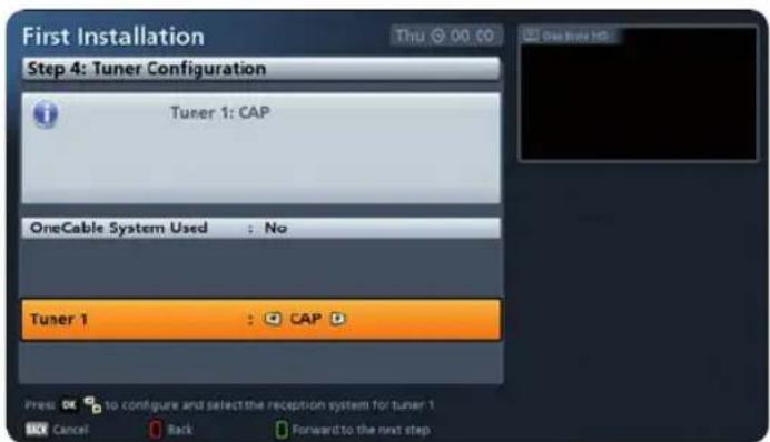
Tuner 1
Select here with the ▲▼ buttons the line "Tuner 1" and then with the ◀▶ keys the "CAP" setting.
First installation
Press the PIP (green) button to move to the next menu.
The following on-screen display appears:

Press the OK button to confirm. During the image display the following message is displayed:

After a successful initialisation the following message appears:

Press the 📄 (green) button to move to the next menu. The following on-screen display appears:
The program list is preinstalled, it is not absolutely necessary to run the channel search (Run channel search = No).

Press the ☐ (green) button to move to the next menu. The message at the bottom left appears, and then the following at the bottom right:
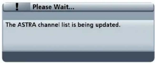

Set Local Time
Here you can use the ▶▶ buttons to select the local time offset to UTC (formerly GMT) (e.g. for Germany: +1 hour). You can set the offset in 0.5 hour steps. The maximum offset is 12 hours (+ and −).
Time setting via
Use the ▶▶ buttons here to select the satellite from which the time information will be obtained.
When you have completed all settings, press the PIP (green) button, to complete the first installation.
15 CAP menu (polar antenna settings)
15.1 Calling up the CAP menu
Press 📄 (green button). One of the following illustrations will be displayed:


You can make further CAP settings from the main menu under "Settings", "Antenna & Satellite", "Tuner Configuration", "Tuner 1" (CAP), "CAP settings".
15.2 Move CAP to park position
Press the ☐(green) button, select with the ▲▼ buttons "Move CAP to park position" and press OK. The CAP menu disappears and the turntable moves to the park position. After that the menu item "Move CAP to park position" is renamed "Move to last satellite".
15.3 Resetting the CAP system (polar antenna) (RESET)
Note
Before exchanging any component of the system (e.g. the receiver) the turntable should be moved to the park position by means of the "Reset CAP system" command. "Reset" deletes all previously saved satellite positions. The satellite data in the receiver component of the UFS 946/CI+are however retained.
Press the ☐ (green) button, select with the ▲ ▼ buttons "Reset CAP system" and press OK. The following on-screen display appears:

Press the OK button to confirm, or the BACK button to cancel.
15.4 CAP settings (main menu)
You can make further CAP settings from the main menu under "Settings", "Antenna & Satellite", "Tuner Configuration", "Tuner 1" (CAP), "CAP settings" (illustration below).
Important
Important basic settings for the CAP can be made in the "CAP settings" menu. These settings should be performed by a specialist to match your particular needs and the conditions; if they are set incorrectly the CAP could be damaged.

15.4.1 Elevation offset
You should not change the setting for the elevation offset unless there has been some mechanic alteration to the elevation which requires manual correction.
Make the settings using the ▶ buttons.
15.4.2 Search speed
In the fringe areas of the satellite footprints it may happen that a better search result is obtained by using a lower CAP search speed. If you do not get satisfactory search results at the "Regular" speed, you can reduce the search speed to "Slow".
However, if the signal strength and quality are good you can set the search speed to "Fast". Normally we recommend the search speed is set to "Regular".
Make the settings using the ▶.buttons.
15.4.3 Start search from park position
On The polar antenna folds out in all cases without any further prompting from the park position and starts the search for a satellite.
Off The user first has to confirm a prompt 1) before the polar antenna folds out and starts the search for a satellite. This prevents the polar antenna from folding out at an unwanted time after the receiver is switched on, such as when in a garage. Off is the default value.
1) see the illustration on page 50.
15.4.4 Restore factory settings
Restores all the settings in the "CAP settings" menu to the factory default settings.
16 Alignment (satellite search)
The antenna is aligned automatically. After the UFS 946/CI+has been switched on, the turntable automatically moves to the last channel received and the associated satellite position (e.g. ARD/ASTRA).
This works because each satellite is automatically recognised by the turntable.
The satellite search is started when you select a channel. If the turntable has not yet saved the position of the satellite, you will see the following display when you select a channel (example):
Note
If the vehicle is not on supports during the search process and people are moving around inside it, there is a risk that movement of the vehicle will mean that the satellite is not found.
The message on the right appears when the rotating antenna is started from the park position and at Start search from park position the value Off has been set.
The message must be confirmed with OK.
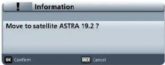
In all other cases the search starts automatically. The search can take several minutes. The following message appears during the search:

As soon as the turntable has found the right satellite it saves its position so that it can find it more quickly next time it starts up. The alignment of the turntable is then optimised automatically for the best signal reception (fine adjustment). The picture can freeze temporarily while this is being done.
17 Channel (satellite) selection
By pressing the + - buttons all the channels can be selected in the sequence that they appear in the current channel list and its sorting. Press the TVR (blue) button to switch between TV and radio channels.
17.1 Channel selection from the channel list
Providing you are not in a menu, pressing the OK button calls up the channel list. The following on-screen display appears:
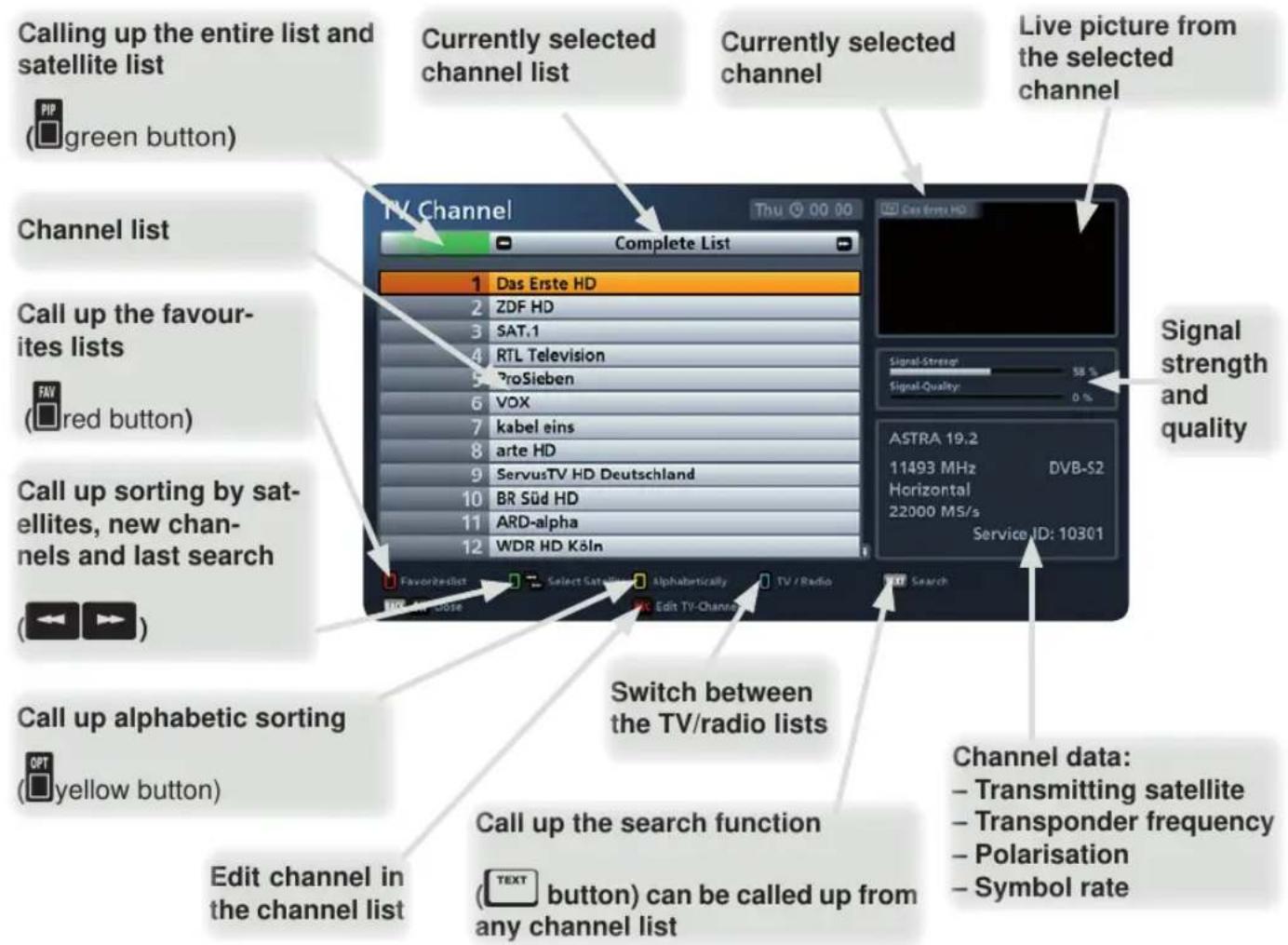
When you open this list the channel list selection / sort order is displayed from where you selected the last channel.
For example, you can use the ASTRA 19.2° or Hotbird 13°). buttons to display various channel lists sorted by satellite (e.g.
The cursor buttons are used to navigate within the respective channel list view to select the desired
channel. The selection of the desired channel is confirmed by pressing the OK button. As soon as the turntable has found the satellite or has reached the known position, you will now hear and view the currently selected channel in the small window at the top right. To exit the channel list and return to the TV picture, press the OK button again, or press the BACK button.
Note
A comprehensive explanation of the channel list with its detailed functions (e.g. the scan and sort function) can be found in the UFS 946/CI+ operating manual.
17.2 Channel selection from the channel list (sorted by satellite)
Proceed as follows to show the channel list sorted by saved satellites. Press (from the TV picture) the OK button, select "Open channel list" and press OK. If you are not in the overall list "green view" now, press (green button). Now select here with the <◀▶> buttons the satellite you want from the available satellites. You are automatically given a channel list that had been stored for the satellite (see example):
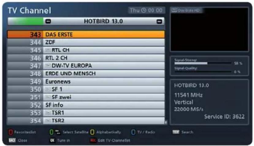
The channel selection works as described previously under "Channel selection from the channel list".
18 Change of location
The turntable automatically recognises a change of location through the built-in GPS receiver 1) . After a minor change of location the turntable moves to the last selected position and so quickly finds the satellite again. After a more major change of location the turntable looks for the satellite on the basis of the GPS data of the new location 1) .
The following message appears while the turntable is moving:

As soon as the turntable has found the right satellite it saves its position so that it can find it more quickly next time it starts up. The alignment of the turntable is then optimised autor best signal reception (fine adjustment). The picture can freeze temporarily while this is being done. If the search is unsuccessful, the following message appears:
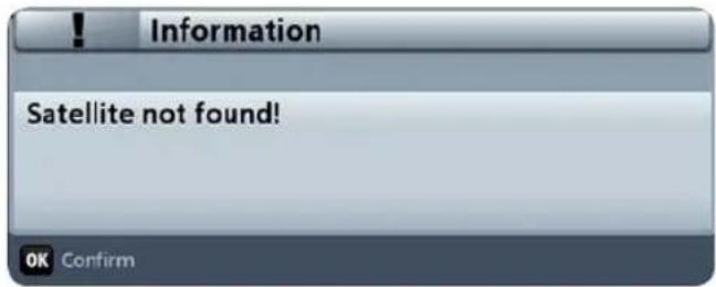
1) The prerequisite for reception of the GPS data is correct wiring; see 5.6.9, p.25.
19 Park
You have the following options to "park" the antenna in the park position:
- Press twice the on/off button (on the remote control or the set).
- Press ☐(green button). Select with the ▲▼ buttons "Move CAP to park position" and confirm with the OK button.
- Switch the ignition on. The antenna and automatically moves to the park position. Prerequisite: The green core of the power supply cable is connected to the ignition and the turntable to the supply voltage (see the connection diagram). Refer to the detailed instructions for this in the CAP unit installation manual.
The following message appears while the antenna is moving into the park position:

20 Special messages from the turntable
20.1 System protection messages
20.1.1 Undervoltage
The following messages are shown on the screen to protect your reception system and the on-board power supply:
The power supply to the turntable is inadequate (battery voltage below the minimum value).
This message means that the turntable can still be operated. However, communication errors between the UFS 946/CI+ and the turntable can occur, for example, when searching for a satellite.
If the battery voltage drops further, then one of the following error messages appears:

Check the power supply to the turntable and whether it is obstructed (e.g. by a branch). If neither of these causes of faults is displayed, the turntable motor temperature is in the critical range. Allow the turntable to stand for a few minutes in its current position until the turntable motor temperature has reduced. You can also however move the turntable to the park position and let it cool down there.
Press the OK button and the turntable moves to the park position.

Press the OK button to confirm the displaye message. The turntable cannot be moved any more. Check the power supply to the turntable.
Note
The antenna should not be moved whilst the battery is being recharged, to prevent peak loads when turning on.
20.1.2 Park position for safety reasons
The vehicle ignition was switched on. For safety reasons, the turntable moves into the park position. This operates however only if the green ignition cable for the turntable is connected to the vehicle ignition and the turntable is connected to the power long as voltage is present at the ignition, the connection to the CAP will remain disabled. This means the CAP cannot be operated.

20.1.3 Obstruction in the swing path
The motorised antenna has reached the mechanical stop or is jammed! If the unit encounters an obstruction, the CAP reverses 10°. This allows the obstruction to be removed more easily.
Check whether the turntable is obstructed (e.g. by a branch).

20.1.4 Overtemperature of the rotation motor
The turntable motor temperature is in the critical range. Allow the turntable to stand for a few minutes in its current position until the turntable motor temperature has reduced.

20.2 Further messages
There is a connection problem between the receiver and the polar antenna. See the table below.
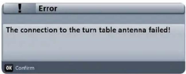
| Possible cause Remedy | |
| The receiver and polar antenna are not connected with the Master cable (marked in red) but with the Slave cable. | Connect the receiver and the polar antenna with the Master cable (marked red) 1) . |
| The ignition is switched on. Switch off the ignition. | |
| There is a voltage at the core (green) marked with "IGNITION". | Check the "IGNITION" core and correct the wiring as required 1) . |
| None of the above reasons. Reset the turntable | 2) .Contact our Service section 3) . |
1) see 5.6.6, p.23 and 5.6.9, p.25.
2) see 15.3, p.48.
3) see 7.2, p.27.
CE
The Kathrein-Werke KG hereby confirm that the designated product complies with the following directives on the harmonisation of the laws.
substances in electrical and electronic equipment
Development, production, quality assurance and marketing are based on the standard
EN ISO 9001.
22 Disposal Instructions
Electronic equipment is not domestic waste - in accordance with directive 2002/96/EC OF THE EUROPEAN PARLIAMENT AND THE COUNCIL dated 27th January 2003 concerning used electrical and electronic appliances, it must be disposed of properly.
At the end of its service life, take this receiver for disposal at a designated public collection point.

Spent batteries are special waste!
Do not throw spent batteries into your domestic waste; take them to a collection point for used batteries.
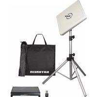
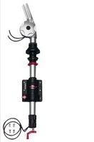


- IMPORTANT
- READ CAREFULLY BEFORE USE
- CONTENTS
- INSTALLATION MANUAL
- OPERATING MANUAL
- 1 GENERAL
- GB
- F
- COMPANY ADDRESS AND ACCREDITED REPRESENTATIVE
- 2 MOBISET 4 CAP 920 COMPONENTS / SCOPE OF DELIVERY
- SCOPE OF SUPPLY
- 3 PROPER USE
- NOTE
- THE SYSTEM MAY BE INSTALLED ONLY BY QUALIFIED SPECIALIST PERSONNEL
- 4 SAFETY INSTRUCTIONS – IMPORTANT NOTES
- SAFETY DURING INSTALLATION WORK
- WARNING
- PLEASE NOTE THAT THERE IS
- PROPER INSTALLATION AND SAFETY
- ESSENTIAL INFORMATION
- ADHESIVE SEALANT
- SAFETY INSTRUCTIONS – IMPORTANT NOTES
- ROAD TRAFFIC LICENSING REGULATIONS (STVZO)
- CABLES
- POWER SUPPLY, FUSING
- NOTICE
- CHECKS BEFORE COMMENCING A JOURNEY
- ANTENNA IN THE PARK POSITION WHILST DRIVING
- 5 INSTALLATION AND CONNECTION
- 5.1 REQUIRED TOOLS AND EQUIPMENT
- 5.2 UNPACKING AND PREPARATION
- 5.3 SELECTING THE INSTALLATION LOCATION
- INSTALLATION AND CONNECTION
- 5.4 INSTALLATION STEPS
- 5.4.1 INSTALLATION OF THE CABLE GLAND AND MOUNTING PLATE
- 5.4.2 INSTALLATION OF THE TURNTABLE
- VARIANT WITH CABLE GLAND UNDERNEATH THE TURNTABLE
- VERSION WITH EXTERNAL CABLE GLAND (FIG. F)
- 5.5 BRIEF INSTRUCTIONS FOR INSTALLING THE TURNTABLE
- 5.6 INSTALLATION OF THE UFS 946/CI
- 5.6.1 SELECTION OF A SUITABLE INSTALLATION LOCATION
- VENTILATION
- CONNECTIONS AND FUSING OF THE UNIT
- 5.6.2 PREPARATIONS
- ATTACHING THE INFRARED SENSOR
- 5.6.3 IMPORTANT INSTRUCTIONS FOR INSTALLATION
- 5.6.4 SUSPENDED INSTALLATION
- 5.6.5 INSTALLATION ON A FIXED FLAT SURFACE
- 5.6.6 LAYING THE CABLES AND CONNECTING THE TURNTABLE
- 5.6.7 CONNECTION OF THE RECEIVERS
- NOTE THAT THE ANTENNA CAN THEN BE LOWERED ONLY WHEN THE POWER SUPPLY IS PRESENT IN ADDITION TO THE IGNITION SIGNAL
- 5.6.8 FUNCTIONAL INSTRUCTIONS FOR CONNECTION TO THE ON-BOARD POWER SUPPLY
- 5.6.9 CONNECTION EXAMPLE FOR 12 V BATTERY CONNECTION
- ① IMPORTANT
- 6 RECEPTION RANGE / FOOTPRINT
- 7 DISMANTLING FOR SERVICING
- 7.1 REMOVING
- 7.2 ADDRESS OF THE SERVICE CENTRE
- 9 MANUAL LOWERING TO PARK POSITION
- 9.1 SAFETY INSTRUCTIONS
- CAUTION
- PLEASE NOTE IN PARTICULAR THAT
- 9.2 MANUAL RETRACTION
- DIMENSIONS
- SECTION 1: IDENTIFICATION OF THE SUBSTANCE/MIXTURE AND OF THE COMPANY/UNDERTAKING
- SECTION 2: HAZARDS IDENTIFICATION
- SECTION 3: COMPOSITION/INFORMATION ON INGREDIENTS
- SVHC
- SECTION 4: FIRST AID MEASURES
- SECTION 5: FIREFIGHTING MEASURES
- SECTION 6: ACCIDENTAL RELEASE MEASURES
- SECTION 7: HANDLING AND STORAGE
- SECTION 8: EXPOSURE CONTROLS/PERSONAL PROTECTION
- SECTION 9: PHYSICAL AND CHEMICAL PROPERTIES
- SECTION 10: STABILITY AND REACTIVITY
- SECTION 11: TOXICOLOGICAL INFORMATION
- TRADE NAME: DEKASYL MS-5
- SECTION 12: ECOLOGICAL INFORMATION
- SECTION 13: DISPOSAL CONSIDERATIONS
- SECTION 14: TRANSPORT INFORMATION
- SECTION 15: REGULATORY INFORMATION
- SECTION 16: OTHER INFORMATION
- DEKASYL MS-5 HIGH TACK ADHESIVE & SEALANT
- PRODUCT
- APPLICATIONS
- FEATURES
- ADHESION
- METHOD OF USE
- DEKALIN
- HIGH QUALITY PRODUCTS
- FOR MOTORHOME, CARAVAN AND TRAILER TENT
- TECHNICAL DATA SHEET
- TECHNICAL DATA
- STORAGE STABILITY
- SAFETY PRECAUTIONS
- TRANSPORT CLASSIFICATION
- THE OPERATING MANUAL PART FOR THE
- CAP 920
- STARTS FROM THIS PAGE
- 13 IMPORTANT INFORMATION FOR CAP 920 BEFORE SETUP
- REMOTE CONTROL
- 14 FIRST INSTALLATION
- FIRST INSTALLATION
- VIDEO OUTPUT VIA
- HDMI/YPBPR RESOLUTION
- FORCE 576I (MUST BE SUPPORTED BY THE TV SET OTHERWISE YOU WILL NOT SEE A TV PICTURE)
- HDCP FOR FREE CHANNELS
- TV CONTROL BOX VIA HDMI (CEC)
- SHOW 4:3 EVENT
- AUDIO FORMAT VIA HDMI
- AUTO DOLBY DIGITAL OUTPUT
- TUNER 1
- SET LOCAL TIME
- TIME SETTING VIA
- 15 CAP MENU (POLAR ANTENNA SETTINGS)
- 15.1 CALLING UP THE CAP MENU
- 15.2 MOVE CAP TO PARK POSITION
- 15.3 RESETTING THE CAP SYSTEM (POLAR ANTENNA) (RESET)
- 15.4 CAP SETTINGS (MAIN MENU)
- 15.4.1 ELEVATION OFFSET
- 15.4.2 SEARCH SPEED
- 15.4.3 START SEARCH FROM PARK POSITION
- 15.4.4 RESTORE FACTORY SETTINGS
- 16 ALIGNMENT (SATELLITE SEARCH)
- 17 CHANNEL (SATELLITE) SELECTION
- 17.1 CHANNEL SELECTION FROM THE CHANNEL LIST
- 17.2 CHANNEL SELECTION FROM THE CHANNEL LIST (SORTED BY SATELLITE)
- 18 CHANGE OF LOCATION
- 19 PARK
- 20 SPECIAL MESSAGES FROM THE TURNTABLE
- 20.1 SYSTEM PROTECTION MESSAGES
- 20.1.1 UNDERVOLTAGE
- 20.1.2 PARK POSITION FOR SAFETY REASONS
- 20.1.3 OBSTRUCTION IN THE SWING PATH
- 20.1.4 OVERTEMPERATURE OF THE ROTATION MOTOR
- 20.2 FURTHER MESSAGES
- CE
- 22 DISPOSAL INSTRUCTIONS
- SPENT BATTERIES ARE SPECIAL WASTE
Brand : KATHREIN
Model : MobiSet 4 Twin CAP 920
Category : Satellite receiver