
MobiSet 3 Twin CAP 720 - Satellite receiver KATHREIN - Free user manual and instructions
Find the device manual for free MobiSet 3 Twin CAP 720 KATHREIN in PDF.


| Product Type | Satellite receiver system |
| Brand | KATHREIN |
| Model | MobiSet 3 Twin CAP 720 |
| Part Number | 20310023 |
| Application | Digital satellite TV and radio reception for caravans and motorhomes |
| Frequency Range | 10.70 - 12.75 GHz |
| LNB Outputs | 2 (Master and Slave) |
| Polarization | Vertical/Horizontal, Low/High switching |
| Elevation Range | 0° to 75° |
| Azimuth Range | 0° to 370° (continuous rotation) |
| Skew Adjustment | ±45° |
| Power Supply | 12 V DC (10.9 - 13.8 V) from vehicle battery |
| Power Consumption (max) | 12 A peak, typical 3 A search, 1.2 A reception, 0.024 A standby |
| Weight (turntable with reflector) | 9.7 kg |
| Dimensions (parked) | Height 246 mm, Mounting plate diameter 282 mm |
| Turning Diameter | 162 cm (clearance required) |
| Cable Lengths | 8 m + 3 m coax, 10 m power cable |
| Search Time (first satellite) | 10 - 120 seconds |
| Search Time (subsequent) | 2 - 30 seconds |
| Compatible Receiver | UFS 940sw / 740sw DVB-S receiver |
| Max Vehicle Speed (dish lowered) | 130 km/h |
| Operating Temperature | -20°C to +45°C |
| Safety Features | Automatic park on ignition, collision detection, motor temperature protection |
| Installation | Fixed roof mount with adhesive and screws (by qualified personnel) |
| Warranty | Standard manufacturer warranty (void if improper installation) |
Frequently Asked Questions - MobiSet 3 Twin CAP 720 KATHREIN
User questions about MobiSet 3 Twin CAP 720 KATHREIN
0 question about this device. Answer the ones you know or ask your own.
Ask a new question about this device
Download the instructions for your Satellite receiver in PDF format for free! Find your manual MobiSet 3 Twin CAP 720 - KATHREIN and take your electronic device back in hand. On this page are published all the documents necessary for the use of your device. MobiSet 3 Twin CAP 720 by KATHREIN.
USER MANUAL MobiSet 3 Twin CAP 720 KATHREIN
You can obtain an English version of our installation instructions from our representatives in your country (http://www.kathrein.de/include/kontakte_groups_eng.cfm?kontinent=1&gruppe=SAT) or download one from our homepage (http://www.kathrein.de/en/sat/index.htm).
F
COMPANY ADDRESS AND ACCREDITED REPRESENTATIVE
KATHREIN-Werke KG
Managing Director of KATHREIN-Werke KG
MOBISET 3 TWIN CAP 720 COMPONENTS/SCOPE OF DELIVERY
- Roof gland with retaining nut
- Mounting plate
- Turntable with integral controls
- Antenna carrier
- Parabolic reflector
- Twin LNB


UFS 940sw (Front view)
See the UFS 940sw operating manual for a rear view of the receiver together with explanation of functions and operating instructions.
SCOPE OF SUPPLY
The MobiSet 3 Twin CAP 720 consists of:
• Turntable complete with control electronics, pre-assembled parabolic reflector with LNB
- Mounting plate
- Complete cabling set with 8-m coax cable, 3-m coax cable and 10-m power supply cable for connection to the vehicle power supply
• Roof gland with sealing gasket
• Sikaf1 ex® 291i adhesive sealant (100 ml tube)
• UFS 940sw HDTV-DVB-S receiver with connecting cables, infrared sensor and infrared remote control
- MobiSet 3 Twin CAP 720 installation and operating instructions
• UFS 940sw satellite receiver operating manual
CONTENTS (INSTALLATION MANUAL)
GENERAL....2
MOBISET 3 TWIN CAP 720 COMPONENTS/SCOPE OF DELIVERY 3
CONTENTS.... 4
PROPER USE 6
SAFETY INSTRUCTIONS - IMPORTANT INFORMATION 7
INSTALLATION AND CONNECTION.... 10
INSTALLATION OF CABLE GLAND AND MOUNTING PLATE 12
INSTALLATION OF TURNTABLE 15
BRIEF INSTRUCTIONS FOR INSTALLING THE TURNTABLE 18
INSTALLATION OF THE UFS 940SW 20
LAYING CABLES AND CONNECTING THE TURNTABLE 25
CONNECTING TO THE UFS 940SW 25
FUNCTIONAL INSTRUCTIONS FOR CONNECTION TO THE ON-BOARD POWER SUPPLY.... 26
CONNECTION EXAMPLE FOR 12 V BATTERY CONNECTION 27
RECEPTION RANGE/FOOTPRINT 28
DISMANTLING FOR SERVICING.... 29
DISMANTLING 29
ADDRESS OF THE SERVICE CENTRE 29
POLARISATION SETTING 30
POLARISATION SETTING 30
SAFETY NOTES 32
SETTING OPERATIONS.... 32
MANUAL LOWERING TO PARK POSITION 35
SAFETY INSTRUCTIONS 35
MANUAL LOWERING.... 36
TECHNICAL SPECIFICATION 37
SIKAFLEX® 291i SAFETY DATA SHEET 40
SIKAFLEX® 291i TECHNICAL DATA SHEET 45
CONTENTS (OPERATING MANUAL)
CAP 720 OPERATING MANUAL.... 47
IMPORTANT INFORMATION FOR CAP 720 BEFORE SETUP .... 48
REMOTE CONTROL 48
FIRST INSTALLATION 49
CAP MENU (TURNTABLE ANTENNA SETTINGS) 53
CALLING UP THE CAP MENU 53
RESETTING THE CAP SYSTEM (TURNTABLE ANTENNA) (RESET) 53
INPUTTING THE CAP GPS POSITION 54
TO MOVE THE ANTENNA MANUALLY 54
ELEVATION....55
LNB TILT/SKEW 55
STOP ON SIGNAL 55
MOVE TO THE AZIMUTH (ROTATE THE ANTENNA) 55
MOVE CAP TO PARK POSITION.... 56
CAP SETTINGS.... 56
ELEVATION BORDER AND ELEVATION OFFSET 56
SEARCH SPEED 56
ALIGNMENT (SATELLITE SEARCH) 57
CHANNEL (SATELLITE) SELECTION/PROGRAMMING THE TIMER 58
CHANNEL SELECTION FROM THE CHANNEL LIST 58
CHANNEL SELECTION FROM THE CHANNEL LIST (SORTED BY SATELLITE).... 59
CHANGE OF LOCATION.... 60
PARK....61
PARKING THE TURNTABLE 61
SPECIAL MESSAGES FROM THE TURNTABLE 62
DECLARATION OF CONFORMITY 66
DISPOSAL INSTRUCTIONS.... 67
PROPER USE
PROPER USE (USE FOR THE INTENDED PURPOSE)
The MobiSet 3 Twin CAP 720 is designed to receive digital TV and radio programs via satellite. The automatic positioner is intended to be used as a turntable for the parabolic reflector.
The turntable can be used to receive digital TV and radio signals in the frequency range from 10.70 to 12.75 GHz; the antenna cannot receive terrestrial signals (e.g. DVB-T).
The turntable can only be used in conjunction with the UFS 940sw/740sw DVB-S receiver on the master cable.
In conjunction with these receivers, the turntable provides fully automatic alignment of the parabolic reflector to receive digital satellite signals. In addition, any conventional digital satellite receiver can be connected to the slave cable. The turntable is designed for use on stationary caravans or motor homes.
Any use other than that specified above will invalidate the warranty or guarantee.
The following circumstances result in the loss of all warranty and liability claims towards the manufacturer:
- Improper installation
- Use of non-specified mounting materials, which cannot guarantee the mechanical reliability of the antenna system
- Impermissible use, e.g. use of the reflector dish for storage
- Structural changes or interference with the components and mounting accessories in the set, which could endanger both the mechanical and functional reliability
- Improper or forcible opening of the components
- Use of cleaners containing solvents, such as acetone, nitro-cellulose combination thinners, petrol etc.
- Failure to observe installation and safety instructions in this manual
Note:
The maximum permissible speed for vehicles with a CAP 720 receiver unit mounted on the roof is 130 km/h. Before commencing a journey, the satellite dish must always be lowered into horizontal position (park position).

The turntable may be operated in an ambient temperature range of -20\ °C to +45\ °C . Operating the system outside this range may result in malfunctions or damage to the system. When choosing the location for installation or raising the UFS 940sw, ensure there is adequate ventilation.
The system may only be installed by qualified specialist personnel!
To prevent hazards during installation, operation or when driving on public highways, the instructions and information in this manual must be strictly adhered to. Proper installation and connection of the system are pre-requisites for conformity with the corresponding standards.
This is documented in advance by the CE mark and the declaration of conformity in the appendix to this manual.
SAFETY INSTRUCTIONS - IMPORTANT INFORMATION
Safety during installation work

When carrying out installation work in locations where there is a risk of falling, take appropriate safety precautions, e.g. use of a working platform. Make sure that the vehicle roof is sufficiently strong and stable to carry out the installation work (risk of damage or collapsing of roof).
In case of doubt, contact a qualified specialist dealer or the manufacturer of your vehicle to find an appropriate installation location.
Make sure that:
- The turntable and connected units are disconnected from the power supply
- The person carrying out the installation or repair does not suffer from vertigo and can move around safely on the roof of the caravan or motor home
- The person carrying out the installation or repair is wearing sturdy and non-slip shoes
- The person carrying out the installation or repair has a secure position to stand and hold on while working
- The roof and the climbing equipment used (e.g. ladder) are dry, clean and non-slip
- The roof can withstand the weight of the person carrying out the repairs
Caution! Risk of death or injury due to falling or the roof collapsing!
- Nobody should be inside the caravan/motor home underneath the antenna during dismantling/installation
Caution! Risk of death or injury due to possible roof collapsing and falling parts!
Proper installation and safety
Essential information
A crucial safety factor is proper performance of installation and electrical connection work, and the specified alignment of the turntable in the direction of travel (park position), see also installation and connection.
Comply as precisely as possible with the installation conditions and steps described.
Modifications to the electrical installations in the vehicle should only be carried out by a specialist in vehicle electrics. Do not make any unauthorised changes to the turntable.
Adhesive sealant
The turntable is attached to the roof of the vehicle by adhesive and is secured by additional screws.
Note that the curing of the adhesive sealant is temperature-dependent. It reaches its full strength only after approximately five days.

During installation work, comply strictly with the processing and safety instructions for the adhesive sealant (Sikañi ex® 291i safety data sheet and Sikañi ex® 291i technical data sheet).
SAFETY INSTRUCTIONS - IMPORTANT INFORMATION
Road Traffic Licensing Regulations (StVZO)
The applicable regulations of the StVZO must be observed in respect of fixed installation of the turntable on a vehicle which is driven on public highways.
In particular, §§ 19/2; 30 C; 32 (2) and the EC directive 74/483 EEC are applicable.
Briefly, they state that no endorsement of the vehicle documentation is required unless the antenna unit causes the height of the laden vehicle to exceed 2 m, or the antenna unit projects beyond the outer lateral outline of the vehicle. The maximum permissible height of 4 m (vehicle and antenna unit) may not be exceeded.

There is an increased risk of accidents if the normal vehicle height is increased by extending the antenna. The driver bears sole responsibility for the condition of the superstructure and external fittings!
Cables
Lay all cables such that nobody can tread on them or trip over them.
To prevent parasitic induction or interference emissions, when extending the antenna cable use 75 Ω coaxial cable with a screening factor of at least 75 dB.

If you tied the cables together with wire or similar materials, remove this to prevent the risk of fi re!
When connecting the power cables (receiver and turntable) to the vehicle electrical supply, make sure that the cable polarity is not reversed.

If the cable polarity is reversed there is a risk of thermal overload and damage to components when the equipment is powered up!
Power supply, fusing
Operate the system from your vehicle's battery (12 V) or a suitable mains power supply unit. This mains power supply unit must ensure a stable output voltage of 12 V, continuous current of 11 A and 15 A (300 ms) surge current.
The peak current consumption is up to a maximum of 12 A.
To ensure reliable functioning of the connection/control unit, the power supply cable must be connected directly to the battery. If the supply voltage is too low, the UFS 940sw receiver indicates this with the on-screen message "On-board voltage too low!" on the television screen.
A 15 A fuse is incorporated in the power supply cable. If the fuse blows, rectify the source of the fault and replace the blown fuse with a fuse of the same rating (15 A).

Never remove or bypass the fuse in the cable – cable fi re hazard!
Connecting the power supply cable lead marked “Ignition” activates the turntable function for automatic lowering of the antenna. This lowering takes place as soon as the vehicle ignition circuit is turned on. When connecting the control unit to the vehicle power supply, make sure that the “+12V”, “Earth” and “Ignition” wires cannot be disconnected by intermediate switches, as this could deactivate the automatic lowering function.
SAFETY INSTRUCTIONS - IMPORTANT INFORMATION

The antenna will be lowered within 12 seconds of the ignition being switched on (if the unit is in stand-by mode or the UFS 940sw is switched off). Otherwise the control unit that is in use is lowered immediately.
Important: Lowering the antenna can take up to 30 seconds after the ignition is switched on and operates only if the turntable is connected to the 12-V power supply and to the ignition switch!
Checks before commencing a journey
- Before commencing a journey, the antenna must always be lowered into horizontal position (park position). If the antenna has collided with a fixed or movable object, check that it is still securely attached.
- As the antenna is subjected to vibration loads during driving, you should check at regular intervals, depending on the frequency of driving, that the system is still securely attached and tighten any parts that have worked loose.
- The maximum permissible speed for vehicles with a receiver unit mounted on the roof and the antenna lowered is 130 km/h.
- Lower the antenna if it will not be used for a long period. This makes the securing bolts more difficult to access (protection against theft).
Antenna in the park position whilst driving
The antenna must always be lowered into horizontal position (park position) while driving. As a reminder, attach the sticker from the supplementary sheet “Lower the CAP 720 antenna while driving” where it can easily be seen by the person operating the ignition switch.


Safety precautions during operation
During operation of the turntable, make sure that no persons, in particular children, are in the immediate vicinity of the turntable and that they cannot touch any moving parts – crush hazard!
Always unplug the power supply during installation work.

Exceeding the normal vehicle height by failing to lower the antenna increases the risk of accidents! The driver is responsible for the condition of external fittings on the vehicle!

In addition the instructions in the installation and operating manuals for these devices and for the attachments and superstructures must be complied with at all times!

If stormy weather is expected, the turntable must always be moved to the park position, otherwise both the CAP 720 and the vehicle may be damaged.
INSTALLATION AND CONNECTION
REQUIRED TOOLS AND EQUIPMENT
• Circular cutter, ∅ 38 mm
- Flat-bladed screwdriver for M5 screws
- Power drill
- Galvanised round head screws, depending on the roof structure ( : 5 mm, sheet metal screws D 7981, depending on the roof structure) or round head screws D 7985 with washers and nuts
- Twist drill, ∅ 2.5 or 5.5 mm
• Round file and/or emery paper
- Cleaning agent
- Open-ended or ring spanners 10 and 11 mm across flats
- Knife
• Cross-head screwdrivers for M3 and M5 screws
- Torque wrench capacity 6 to 11 Nm
• Hexagon socket key (5 mm)
- Two wooden beams for supporting the turntable
UNPACKING AND PREPARATION
The CAP 720 must not be carried on the satellite dish, since this can cause the dish to distort. Keep the CAP 720 in its cardboard box for transport on to the vehicle roof.
Retain the original packaging, as if it is necessary to send the unit for repair transport damage cannot be ruled out and the manufacturer accepts no liability for possible damage.
Loosen the six fastening screws (width A/F: 10 mm). Carefully lift the turntable off the mounting plate and place it on the prepared wooden supports. Make sure that the cables are not crushed where they emerge from the underside of the turntable.

The CAP 720 packaging can be opened along both long sides. This allows easier access to the fastening screws.
SELECTING THE INSTALLATION LOCATION
Essentially, the cable lengths of the MobiSet 3 Twin CAP 720 components allow you a free choice of installation location on your caravan or motor home.
However, you should take note of the following points:
- Before installation, you should find out whether the operating manual for your vehicle permits the fitting of non-vehicle-specific parts or what requirements need to be met in order to do so.
- For direct satellite reception, there should be no obstructions between the antenna and the satellite. Therefore, make sure that the antenna is not shadowed by roof extensions such as luggage racks, air conditioning units, solar panels, etc. The problem of shadowing applies also to the selection of the parking place for your vehicle. For interference-free satellite reception, the antenna needs a projected free view to the South at an angle of between 0° and 75° (depending on location) to the horizontal.
INSTALLATION AND CONNECTION
- When selecting the installation position, take into account the range of movement of the turntable (see graphics and the "Technical Data" chapter). There must be no structures on the roof that would obstruct this range of movement (risk of collision). For safety, keep at least the required area free (for ease of installation and any subsequent dismantling).

INSTALLATION AND CONNECTION
- Choose an installation position on the roof that is as horizontal as possible or only slightly sloping, depending on the location of the vehicle, since roof inclinations greater than 5° may lead to problems when searching for the satellite.
- To ensure secure adhesion, the height difference of the roof curve may not be more than 1 cm over a length of 2 m, as otherwise the gap between the roof and the mounting plate would be too great to be filled by the adhesive sealant.
- As the vehicle is constantly subjected to vibration loads during travel, the roof below the antenna unit is also subject to significant loads. Please note given the nature and capacity of your vehicle roof (see also operating manual for the vehicle) that the weight of the antenna unit is approx. 9.7 kg. In case of doubt, consult a qualified dealer or your vehicle's manufacturer.
- The roof gland provides a watertight seal through which the three connecting cables (coax cable and power supply cable) are fed into the interior of the vehicle directly underneath the turntable. If you prefer a different method of laying the cables, they can be run from the rear of the turntable via the channel provided in the mounting plate. The cables must then be run along the roof of the vehicle in a protective cable duct and through a separate HDZ 100 roof gland (neither supplied).
- The HDZ 100 roof gland is available as an accessory under part number 20410032 from specialist dealers.
Note: Do not cut the cables short, as otherwise the proper functioning of the unit can no longer be guaranteed.
INSTALLATION STEPS
INSTALLATION OF CABLE GLAND AND MOUNTING PLATE
Note: If you had previously used a Kathrein HDM140/141 flexible satellite mast or another mast with a diameter of 34 mm, you can continue using the existing gland hole in the roof (if space allows).
Figure: A

- In the centre of the intended position of the turntable, drill the opening for the cable gland with a circular cutter (Ø: 38 mm). Deburr the hole with a round file or emery paper.
- Provisionally insert the roof gland into the drilled hole (Fig. A).
INSTALLATION AND CONNECTION
- Place the mounting plate on the roof of the vehicle, such that the centre hole is positioned centrally to the cable gland. The arrow symbol must be visible from above and point forwards in the direction of travel (Fig. B).
Figure: B

- Mark out the positions of the six fastening holes on the roof of the vehicle in a circular pattern.
Note: The size of the holes and the choice of fastening screws to be used (not supplied) depend on the type and thickness of the materials used in the roof structure. If the roof panelling (plastic roofs) is sufficiently strong, it is recommended that round head screws, plain washers and self-locking nuts are always used to secure the glued mounting plate.
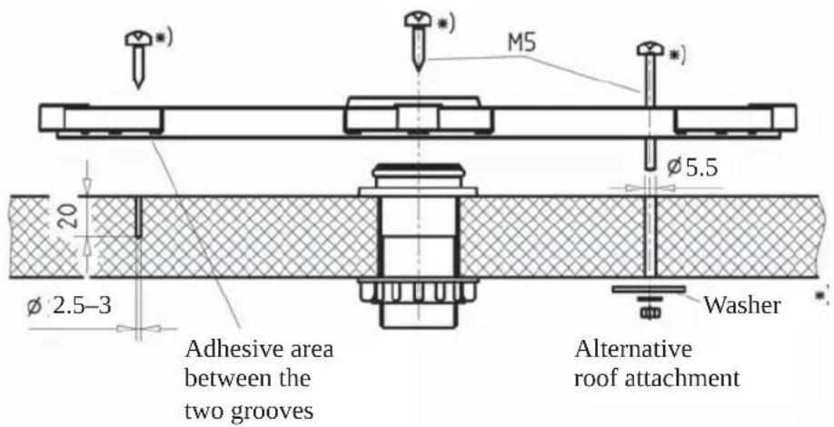
- For very thin roof panel materials and insufficient support in the insulating material, through holes ( : 5.5 mm) into the interior of the vehicle are necessary; galvanised M5 round head screws of sufficient length should then be used.
Make sure that you use a sufficiently strong support that can accept the screw tensile forces (large plain washers or a complete reinforcing plate).
Figure: C
*) Not included
INSTALLATION AND CONNECTION
- Create the holes necessary to secure the mounting plate (Fig. C).
- In addition to the screwed connection, the mounting plate and roof gland must be bonded to the roof with adhesive and sealed. This is done using the Sikafi ex® 291i adhesive sealant supplied, which is ideally suited for this purpose thanks to its broad range of adhesion.
Before starting to use Sikan ex® 291i adhesive sealant, be sure to read the Sikan ex® Products safety data sheet and technical data sheet in this installation manual!
The prerequisite for good adhesive characteristics is a clean, dry and grease-free substrate. You should therefore clean the roof surface with a suitable cleaning agent within a circumference of 35 cm around the drilled hole and allow the surface to dry thoroughly.
If the surface is painted, ensure that the paint finish is sufficiently well bonded to the substrate.
If the coat of paint is already loose or peeling, it must be removed down to a stable layer in the area to which the adhesive will bond. If you have any doubts concerning the adhesive characteristics, consult a paint and lacquer specialist, or the manufacturer of your vehicle.
Under certain circumstances, it may be necessary for you to improve the adhesive properties of the roof surface by pre-treatment with a cleaning agent available from specialist dealers (e.g. Sika® Cleaner) or a primer (e.g. Sika® Primer).
The procedure for gluing the mounting plate is as follows:
Figure: D

Adhesive areas between the two grooves
INSTALLATION AND CONNECTION
- Ensure before starting adhesive work that the temperature of materials to be glued and the adhesive sealant is between +5 °C and +40 °C. Prepare all necessary fasteners and tools.
- Prepare the tube of adhesive sealant in accordance with the instructions enclosed with the tube.
- Remove the roof gland (Fig. A) and apply the adhesive sealant evenly to the underside of the roof gland fl ange.
Replace the roof gland in the drilled hole and press it firmly against the roof of the vehicle.
- Apply the adhesive sealant evenly to the underside of the mounting plate, completely covering the area within the circular groove (Fig. D).
This area of the vehicle roof must be completely coated with adhesive in order to achieve the necessary bonding force.
Place the mounting plate on the roof of the vehicle, as you did previously when marking out the drilled holes.
Make sure that the arrow on the mounting plate points forward in the direction of travel.
The fastening holes must be perfectly aligned with the prepared holes in the roof.
- Fasten the mounting plate in place with the prepared screws, evenly tightening six screws across the diagonals.
Note: The adhesive sealant used is capable of filling small gaps caused by the curvature of the vehicle's roof. However, you should ensure that the mounting plate is not bent by tightening the screws.
- Remove any adhesive sealant that leaks out at the sides with a clean cloth or if necessary with Sikaf1 ex® Remover (available from specialist dealers). Do not use cleaning agents or thinners containing solvents, as this could damage the adhesive sealant applied under the mounting plate. Use only cleansing paste and water to clean your hands.
- Secure the cable gland from inside the vehicle by tightening the ribbed nut supplied (Fig. A).
- Note that the curing of the adhesive sealant depends on the ambient temperature and the humidity. Final strength is reached only after approx. five days. However, this need not restrict further installation work, since the mounting plate is held in place by the tightened screws.
INSTALLATION OF TURNTABLE
VARIANT WITH CABLE GLAND UNDERNEATH THE TURNTABLE
- Feed the ends of the cables with the connectors as far as possible through the cable gland into the interior of the vehicle.
INSTALLATION AND CONNECTION
Figure: E

- Lift up the turntable and place it carefully on the mounting plate facing in the direction of travel (see illustration Fig. E) (do not step on the plug connector and do not kink/crush the cables!).
The through holes on the turntable must be perfectly aligned with the threaded holes on the mounting plate. When lowering, make sure that the cables are fed through the cable gland and are not crushed. - Apply a little adhesive sealant to the six threaded holes in the mounting plate and screw the fastening screws into the thread. Tighten the screws to a torque of 6 Nm.
- To prevent water vapour from inside the vehicle reaching the turntable through the roof gland, thread the three cables through the sealing gasket supplied (see Fig. E) and insert this into the roof gland until it reaches the stop. Make sure that no tensile load is acting downwards on the sealing gasket as this can cause it to fall out in the course of time.
INSTALLATION AND CONNECTION
VERSION WITH EXTERNAL CABLE GLAND (FIG. F)
Direction of travel
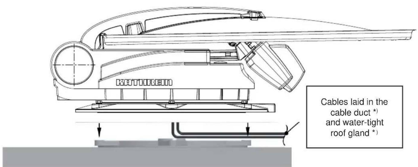
*) Not included! The HDZ 100 roof gland is available as an accessory under part number 20410032 from specialist dealers.
- The external roof gland is arranged so that it forms a water-tight enclosure on the vehicle roof around the point where the three cables projecting from the turntable are connected to the extension cables within the interior of the vehicle, and where if necessary they can be disconnected.
- Arrange the cables in the cable duct when placing the turntable on to the mounting plate. Make sure that the cables are not crossed over and that they are taut so that they cannot be crushed. Do not try to pull the cables from the unit. This could damage the cables or loosen the cable connections.
- Place the turntable carefully on the mounting plate. The through holes on the turntable must be perfectly aligned with the threaded holes on the mounting plate.
- Apply a little adhesive sealant to the six threaded holes in the mounting plate and screw the fastening screws into the thread. Tighten the screws to a torque of 6 Nm.
- When feeding the cables through the HDZ 100 roof gland, make sure they are not crushed, kinked or damaged.
INSTALLATION AND CONNECTION
BRIEF INSTRUCTIONS FOR INSTALLING THE TURNTABLE

The sequence of pictures shown illustrates all the necessary installation steps that are required to install the turntable and the parabolic reflector on the roof of the vehicle.
The other detailed instructions in this installation and operating manual must also be followed!

Determination of installation location.
Important! System has a turning range of 162 cm (∅). Drill hole with ∅ 38 mm. Deburr sharp edges of hole.

Apply Sikaflex® 291i adhesive to the spigot of the roof gland. Insert the spigot into the hole and secure it from below with the knurled nut.
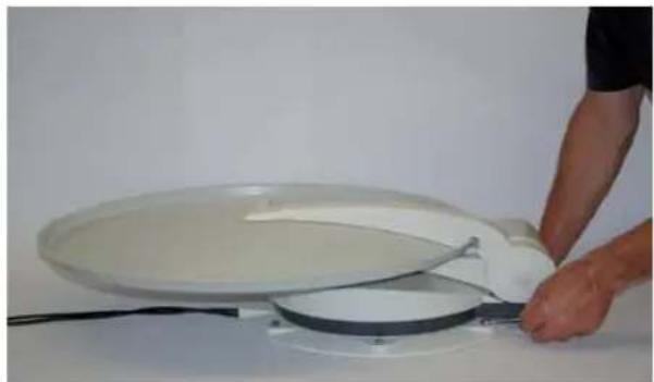
Unscrew screws (x 6, 10 AF) from the mounting plate and remove the mounting plate.
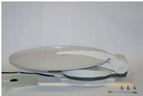
Place the turntable on prepared wooden supports to protect the roof of the vehicle.
INSTALLATION AND CONNECTION

Align mounting plate. Arrow in the direction of travel. Mark out the six holes for securing the mounting plate.

Apply Sikaflex® 291i adhesive in a sinuous line between the two grooves and spread with spatula or similar. Avoid skin contact!

Place mounting plate on roof gland and secure with appropriate screws (choose screws according to thickness/structure of roof).

Screw turntable on to mounting plate using torque wrench.
Important!
Tightening torque: 6 Nm
Set up electrical connections. Connect the UFS 940 receiver. Connect the turntable to the battery.

The antenna must always be lowered into horizontal position (park position) while driving!
Maximum driving speed of the vehicle: 130 km/h
INSTALLATION AND CONNECTION
INSTALLATION OF THE UFS 940SW
SELECTION OF A SUITABLE INSTALLATION LOCATION
Note:
When choosing the installation location, bear in mind that the rear of the unit should always be accessible. The UFS 940sw is equipped with a power saving circuit and a separate infrared transmitter, which means that the unit does not need to be placed where it is visible. You can therefore fit the UFS 940sw out of sight in any location, e.g. on cupboard walls, side walls or the base of storage compartments.
The four screw sockets provided (see diagram on the next page) allow you to install the receiver not only resting on a shelf but also to fix it there or in other positions.
In addition, the following points should be taken into account:
- The wall thickness at the installation location must be at least 15 mm, as otherwise the screws will break through on the other side or damage the surface
- Ensure that the cupboard or storage compartment in which the unit is housed is adequately ventilated, to prevent a build up of heat. Carpet-covered walls are unsuitable for installation
• Take care when tightening the screws not to damage any cables etc. behind or in the wall - The receiver is designed for installation in exclusively dry, interior locations. The installation location must be protected against moisture
- The cable lengths must be taken into account when choosing the installation location
- The connecting cables must be provided with strain reliefs
Ventilation:
The heat generated within the receiver can be dissipated from the following sides of the casing: Bottom, left, right and top. When selecting the installation location, make sure that these sides are not obstructed or covered. If the unit is operated continuously with insufficient ventilation, this can negatively affect the length of its working life!
Maintain a clearance of at least 20 cm above or below the unit, 2 cm to either side and 5 cm behind it, to allow unobstructed dissipation of the heat generated.


The unit monitors its temperature in operation. Premature failure of the unit due to continuous operation at temperatures higher than the recommended operating temperature as a result of insufficient ventilation does not constitute grounds for a claim under warranty/guarantee.
INSTALLATION AND CONNECTION
Connections and fusing of the unit:
All connection cables for connection to the receiver (including the infra-red sensor) are connected at the rear of the unit (see also the item “Connection example” in this section). When selecting the installation location, allow sufficient clearance at the rear of the unit for these cables and their plugs.
On the left hand side of the receiver viewed from the front there is a fuse inserted from the outside. This fuse (for the type, see the section "Important Information" in the receiver operating manual) should be accessible even after the unit has been installed, so that it can easily be exchanged if required.
PREPARATIONS
Removing the blanking plugs:
When the unit is delivered, the screw sockets are covered with blanking plugs. These can be pushed out, using the screws supplied (working upwards from below, see diagram on the right).
Attaching the infra-red sensor:
If the unit is installed in open view, you can attach the infra-red sensor directly to the unit; or if the receiver is installed in a concealed location, you should position the infra-red sensor where it can be clearly seen by the remote control unit. There are three places on the infra-red sensor where the adhesive strips supplied can be attached (see diagram on the right ①, ② and ③). The attachment point ① is provided for sticking the infra-red sensor directly to the unit.
The attachment point on the receiver is on the front panel (see diagram on the right ④).
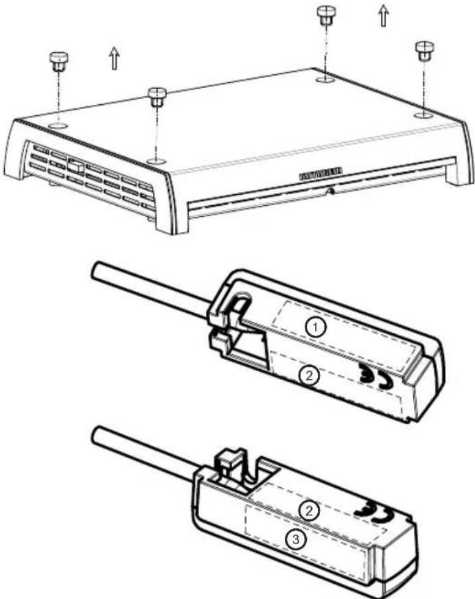
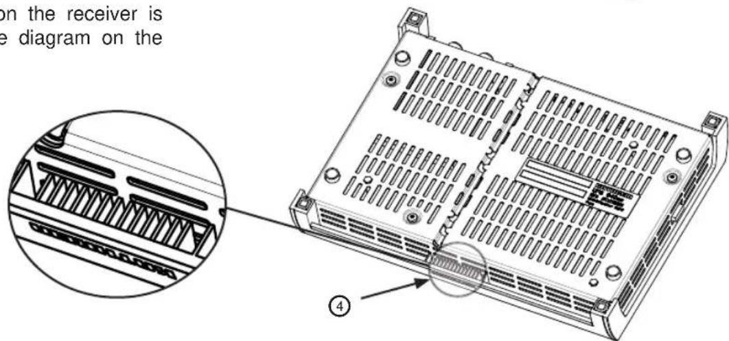
INSTALLATION AND CONNECTION
Using the adhesive strips supplied, now install the infra-red sensor either on the receiver or at the chosen location. If the infra-red sensor is installed on the unit, its cable can be threaded in at its base, as for a phone, and routed to the rear of the receiver (see diagram on the right).

When threading in the cable, take care not to damage its sheath.
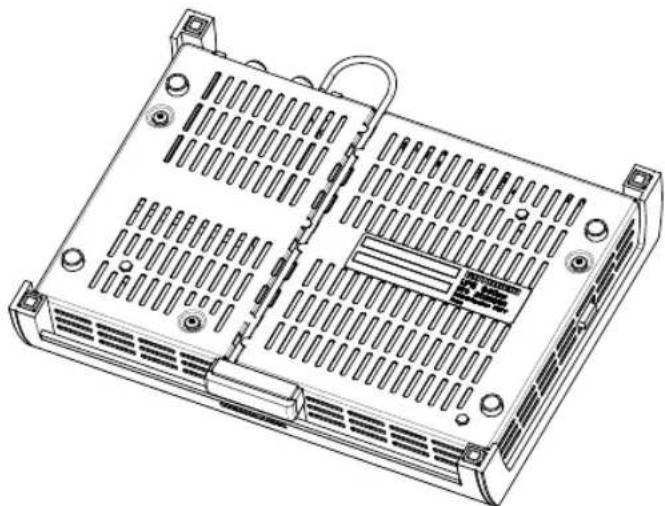
IMPORTANT INSTRUCTIONS FOR INSTALLATION

Under no circumstances use countersunk-head screws for installation (see diagram on the right), since these can damage the screw sockets on the receiver. Wherever possible, use the wood screws supplied with the receiver.

Before installing the receiver so that it is attached to another piece of equipment (such as a TV set), check with the manufacturer of that equipment or by reference to the documentation supplied with it whether this is permissible, and if so what fittings (screws etc.) you need/can use for this. The temperature rise of each of the units in operation (receiver/TV set) can in some circumstances affect the other unit.

The wood screws supplied with the receiver should not under any circumstances be used to attach it to a TV set or other electrical equipment! This could damage that equipment, possibly beyond repair.
Risk of fatal injury due to electric shock!
Use of other screws:
If because of the installation location or factors associated with it, the screws supplied cannot be used, refer to the diagram alongside when selecting the screws to be used. This shows you the cross-section area of the screw sockets on the receiver and shows which screws (diameter, screw head profi les etc.) can be inserted into the receiver support.

INSTALLATION AND CONNECTION
Useful information for installing the receiver on a TV set:
For installation by attachment to the rear of a TV set, securing with two screws is sufficient.
The equipment must have one of the following hole patterns (for wall mounting) on its rear panel: 100 x 100; 100 x 200; 200 x 200 or 200 x 400. If this is not the case, a VESA adaptor plate can be obtained from a specialist dealer.
Before installing the receiver it is essential you read the section "Wall mounting" (or the equivalent) in the user instructions for your TV set. This will tell you the screw diameters (M4, M6 or M8) and most importantly the permissible screw penetration depth.

Before starting any installation work, it is essential you disconnect all the units concerned from the mains. If the screws penetrate too deeply into the TV set they may damage it beyond repair and create the risk of a fatal electric shock!

Under no circumstances install the receiver between the TV and a wall support! Installation on the rear panel of a TV set is permissible only if the TV set is resting on a stand that is attached in some other way.
Marking out the screw/drill points at the installation location:
This diagram is to assist you in marking out the exact screw/drill points at the installation location.

INSTALLATION AND CONNECTION
INSTALLATION
Secure the receiver at the installation location previously selected and prepared.

Do not force it, and take care not to damage either the screw sockets, the receiver casing itself or any cables that are already attached to the receiver!


INSTALLATION AND CONNECTION
LAYING CABLES AND CONNECTING THE TURNTABLE
- Lay the master coaxial cable (marked red) to the UFS 940sw and the second coaxial cable to the second receiver. If you are not using a second receiver, we recommend that you lay the second coaxial cable in any case, so that it is available should you ever need it.
- Lay the turntable power supply cable (3-pin plug) to the battery.
Avoid laying the cables across sharp edges and secure the cables against possible chafing points.
- Connect the Master coaxial cable (coming from the turntable) to the "IF IN" F socket on the rear of the UFS 940sw.
- Place the infrared sensor for the receiver close to or directly on top of the TV set and lay the cable to the UFS 940sw. Connect the 6-pin Western connector at the rear to the socket marked "IR REMOTE IN" (see also "Installation of the UFS 940sw receiver" in this section).
Note: Lay the Cinch cable supplied with the CAP 720. Take great care to plug the cable into the correct socket!
CONNECTING TO THE UFS 940SW

The receiver must be connected to no other power supply than 12 V DC. The receiver's earth connection must be connected to the negative pole of the motor home or caravan battery.
Isolate the on-board power supply (master switch “off” or disconnect the positive pole of the on-board power supply battery) before commencing the following work:
- Connect the power cable supplied (depending on the power supply available in your motor home or caravan, either a 12 V supply or a 230 V supply via a power supply unit) to the "12V == /2.5A" socket on the receiver.
Make sure that the “inline” integrated fuse (5 A) of the cable is fully plugged in and is intact. If the fuse blows, the source of the fault must first be eliminated. The fuse must only ever be replaced by a fuse with the same rating (5 A).

The fuses in the cable and in the receiver must never be by-passed – cable fire hazard!
- At the connecting point for the power cable, the voltage must not fall below 10.9 V even with a load of 12 A. Otherwise optimum functioning can no longer be guaranteed.
- Connect the power cable to the respective socket in your motor home or caravan (12 V or 230 V).
INSTALLATION AND CONNECTION
Only for connection in a motor home, not in a caravan!
- The green connecting cable, marked “IGNITION” allows you the option of connection to a circuit in the vehicle that is activated when the ignition key is turned and then carries a continuous 12 V supply. This type of connection ensures that when the engine is started the antenna is automatically lowered into the park position (the receiver does not need to be turned on).
Note that the antenna can then be lowered only when the power supply is present at the turntable in addition to the ignition signal!
- Check the connections before you re-connect the on-board power supply.
- For commissioning and more detailed information on additional operator functions, we refer you to the separate operating manual enclosed.
FUNCTIONAL INSTRUCTIONS FOR CONNECTION TO THE ON-BOARD POWER SUPPLY
Under certain circumstances, problems can arise when the units are connected to different connecting sockets or circuits/earth potentials. If no others are available, it is recommended that you connect the connecting sockets for receiver and TV set to the same cable, as shown in Figure "G". The current rating of the circuit used must be checked with respect to the intended application.
Further information on operating the UFS 940sw receiver can be found in the operating manual supplied with the unit.
INSTALLATION AND CONNECTION
CONNECTION EXAMPLE FOR 12 V BATTERY CONNECTION
Figure: G

Important:
For operation with two batteries, it must be ensured that the ignition signal earth has the same potential as the power supply battery earth for the turntable.
Non-compliance means that the automatic lowering function will not work!
Ensure the cable polarity is correct!

RECEPTION RANGE/FOOTPRINT
The footprint is the reception area on the earth that a satellite covers with its transmission beam (spot), within which satellite reception is possible. The transmission power is at its greatest in the centre of this spot – it becomes progressively weaker moving outwards.
You should preferably align your antenna to the position of the ASTRA satellite 19.2° East (picture below left), EUTELSAT/HOTBIRD 13° East (picture below right). The spots for these satellites are shown below.
The inner line of the footprint here shows the area covered by the digital signals from the ASTRA satellite.
The outer dashed line of the footprint displayed here shows the area that is covered by individual ASTRA satellite. Therefore not all channels are available within this footprint.


The satellites broadcast the various channel packages in different footprints. The respective channel packages can normally be received within these footprint zones. In the marginal zones, reception is possible, although because of a variety of influencing factors this cannot be guaranteed. The quality of the channels received can vary considerably (for instance due to environmental factors).
DISMANTLING FOR SERVICING
If repairs to the system or individual components are necessary, contact your specialist dealer or our service centre (see below for address).

Never open the turntable yourself!
DISMANTLING

Do not cut the cables! At the cable junction provided, disconnect the cables projecting from the turntable from the two cables laid within the interior of the vehicle (unplug the plug).
- The cables laid within the vehicle can remain there
- Unscrew the six M6 screws securing the turntable to the mounting plate
- Place two wooden supports on the vehicle roof, for protection
- Then place the turntable on the prepared wooden supports
- To ship the turntable, use the original packaging which you have saved
- Seal the opening in the vehicle roof appropriately to protect against the ingress of moisture
- If a HDZ 100 roof gland has been fitted and the equipment is then removed, the cable channels no longer used should be sealed with the integral plugs. The enclosure is then watertight once again.
Note: Before exchanging the UFS 940sw, the turntable must first be moved to the park position.
ADDRESS OF THE SERVICE CENTRE
Factory repair centre Regional repair centre
ESC
Electronic Service Chiemgau GmbH
Bahnhofstraße 108
83224 Grassau GERMANY
Tel: +49 8641 9545-0
Fax: +49 8641 9545-35 and -36
The LNB for the CAP 720 is factory-set to the polarisation setting "0". In this position you can still receive signals from satellites with differences (between the longitude of the desired reception area and the orbit position of the satellite) of 15° to 20° . For differences greater than this it is best to rotate the LNB and set the necessary polarisation angle.

However, we expressly draw attention to the fact that positioning the LNB at a deviation of up to +45° or up to -45° from the centre position makes sense only if a satellite to the far West or the far East is actually preferred for reception.
The respective setting angle required for the polarisation can be found in the following table.

Longitude for the reception position
Satelliten/Satellites/Satellites
| Land/Country/Pays | TÜRKSAT42° OstEast/Est | ASTRA(Eurobird 1)28.2°OstEast/Est | ASTRA19.2°OstEast/Est | EUTELSATW216°OstEast/Est | HOTBIRD13°OstEast/Est | EUTELSATW110°OstEast/Est | EUTELSATW3A7°OstEast/Est | Thor 2/30.8°WestWest/Ouest | AtlanticBird 35°WestWest/Ouest | AtlanticBird 2/Telecom 2D8°WestWest/Ouest | Hispasat1C/1D30°WestWest/Ouest |
| Albanien/Albania/L’Albanie -23 -2 8 5 | 8 11 15 22 26 28/16 41 | ||||||||||
| Belgien/Belgium/La Belgique -27 -11 | -5 -9 -7 -5 -2 4 8 | 10/-2 25 | |||||||||
| Bulgarien/Bulgaria/Bulgarie -17 4 14 | 10 13 16 19 25 29 | 31/19 41 | |||||||||
| Dänemark/Denmark/Danemark -19 -4 | 2 -3 -1 1 3 8 11 | ’13/1 24 | |||||||||
| Deutschland/Germany/Allemagne -23 | -7 0 -4 -2 0 3 9 | 12 14 /2 28 | |||||||||
| Frankreich/France/France | -32 | -16 | -9 | -13 | -10 | -7 | -5 | 3 | 7 | 10/-2 | 27 |
| Finnland/Finland/Finlande | -7 | 6 | 10 | 5 | 6 | 7 | 9 | 12 | 14 | 15 /3 | 21 |
| Griechenland/Greece/Grèce | -21 2 14 | 1 14 18 21 28 32 | 34/22 46 | ||||||||
| Großbritannien/Great Britain/La Grande-Bretagne | -26 | -13 -8 -13 | -11 | -9 -7 -2 1 3/-9 17 | |||||||
| Italien/Italy/L’Italie | -29 | -10 | -1 | -4 | -1 | 3 | 6 | 15 | 19 | ’22/10 | 37 |
| Irland/Ireland/L’Irlande | -30 | -17 | -12 | -17 | -15 | -13 | -11 -6 -3 | 0/12 | 15 | ||
| Kroatien/Croatia/Croatie | -24 | -5 | 4 | 1 | 4 | 7 | 10 | 17 | 20 | ’23/11 | 36 |
| Liechtenstein/Liechtenstein/Liechtenstein | -26 | -10 -2 -6 | -3 0 2 10 13 | ’16/4 31 | |||||||
| Luxemburg/Luxemburg/Luxembourg | -26 | -11 | -4 | -8 | -6 | -3 | -1 | 6 | 9 | 12/0 | 26 |
| Monaco/Monaco/Monaco | -31 | -13 | -5 | -9 | -6 | -3 | 0 | 9 | 13 | ’16/4 | 32 |
| Niederlande/Netherlands/Les Pays-Bas | -25 | -10 -4 -8 | -6 -4 -1 5 8 | 10/-2 24 | |||||||
| Norwegen/Norway/Norvège | -11 | 2 | 6 | 1 | 2 | 4 | 5 | 9 | 10 | 12/0 | 19 |
| Österreich/Austria/L’Autriche -24 -6 2 | -2 0 3 6 13 16 | ’18/6 | 32 | ||||||||
| Polen/Poland/Pologne | -17 | 0 | 7 | 2 | 5 | 7 | 9 | 15 | 18 | ’20/8 | 31 |
| Portugal/Portugal/Portugal | -43 | -28 | -22 | -26 | -23 | -20 | -17 | -8 | -3 | 0/-12 | 24 |
| Rumänien/Romania/Roumanie | -16 | 4 | 13 | 9 | 11 | 14 | 17 | 23 | 26 | 28/16 | 38 |
| Schweden/Sweden/Suède | -12 | 1 | 6 | 1 | 2 | 4 | 5 | 9 | 11 | ’13/1 | 21 |
| Schweiz/Switzerland/Suisse | -28 | -11 | -3 | -7 | -5 | -2 | 1 | 8 | 12 | ’15/§ | 30 |
| Serbien-Montenegro/Serbia and Montenegro/Serbie-Monténégro | -21 -1 9 5 | 8 11 14 | 21 | 24 26/14 39 | |||||||
| Slowakei/Slovakia/Slovaquie | -18 | 0 | 7 | 3 | 6 | 8 | 11 | 17 | 20 | ’22/10 | 34 |
| Slowenien/Slovenia/Slovénie -24 -5 3 | -1 2 5 8 15 18 | ’21/9 | 34 | ||||||||
| Spanien/Spain/L’Espagne | -40 | -24 | -17 | -21 | -18 | -15 | -11 | -2 | 3 | ’6/5 | 29 |
| Tschechien/Czech Republic/Republique Tchéque | -21 | -4 | 4 | 0 | 2 | 5 | 7 | 13 | 16 | ’19/7 | 31 |
| Ungarn/Hungary/La Hongrie | -20 | -1 | 7 | 3 | 6 | 9 | 11 | 18 | 21 | ’23/11 | 35 |
Other countries and towns in these countries can be found on the Internet on the Kathrein Home Page under “www.kathrein.de/en/sat/index.htm” menu item “Satellite and terrestrial antenna systems/Technical Information/Azimuth/Elevation”.
POLARISATION SETTING
SAFETY NOTES
We strongly advise that users who are not familiar with the setting operations should not undertake to set the LNB themselves. They should contact a technician or engineer. They may find a suitable person on the campsite.
Make sure that:
- The antenna and connected units are disconnected from the power
- The person carrying out the installation does not suffer from vertigo and can move around safely on the roof of the caravan or motor home
- The person carrying out the settings is wearing sturdy and non-slip shoes
- The person carrying out the settings has a secure position to stand and hold on while working
- The roof and the climbing equipment used (e.g. ladder) are dry, clean and non-slip
- The roof can withstand the weight of the person carrying out the settings
Caution! Risk of death or injury due to falling or roof collapsing!
- During setting operations, make sure that no persons, in particular no children, are in the immediate vicinity of the turntable and that they cannot touch any moving parts - crush hazard! Nobody should be below the antenna inside the caravan / motor home during setting operations.
Caution! Risk of death or injury due to possible roof collapsing and falling parts on the motor home/caravan!
Continue to heed the "Safety Instructions - Important Information" section!
No impediments may be in the turning range (see “Safety information and important points to note”)!
SETTING OPERATIONS
The explanation for this setting procedure is based on the assumption that the entire CAP unit has been properly put together, installed and set up, as described in this installation manual. The safety instructions in the detailed operating manual for the UFS 940sw must also be followed!
The key names refer to the remote control for the UFS 940sw receiver
- Turn on the receiver at the main switch at the rear of the unit.
- Press any of the numeric buttons to bring the receiver into operating mode.
- If necessary, first perform a first installation
-
Wait until the message "Position of Astra is not known. Start Search?" is displayed – cancel this
procedure by pressing the BACK button. -
Press the (green) button.
POLARISATION SETTING
-
Use the ▲▼ buttons to move to the "Antenna Configuration" menu item. Confirm the selection by pressing the OK button.
-
Use the ▲▼ buttons to move to the “to move the antenna manually” menu item. Confirm the selection by pressing the OK button.
-
Now use the numeric keys on the remote control to enter "400" in the "Elevation" line. Shortly after the value has been input, the turntable moves to the desired elevation angle.
-
Turn off the UFS 940sw using the main switch at the rear and disconnect it from the power.
-
Use the socket driver supplied (size 20) to slacken the securing screw of the clamp on the LNB.
-
Rotate the LNB by the required number of degrees (the scale is located on the bottom on the LNB).
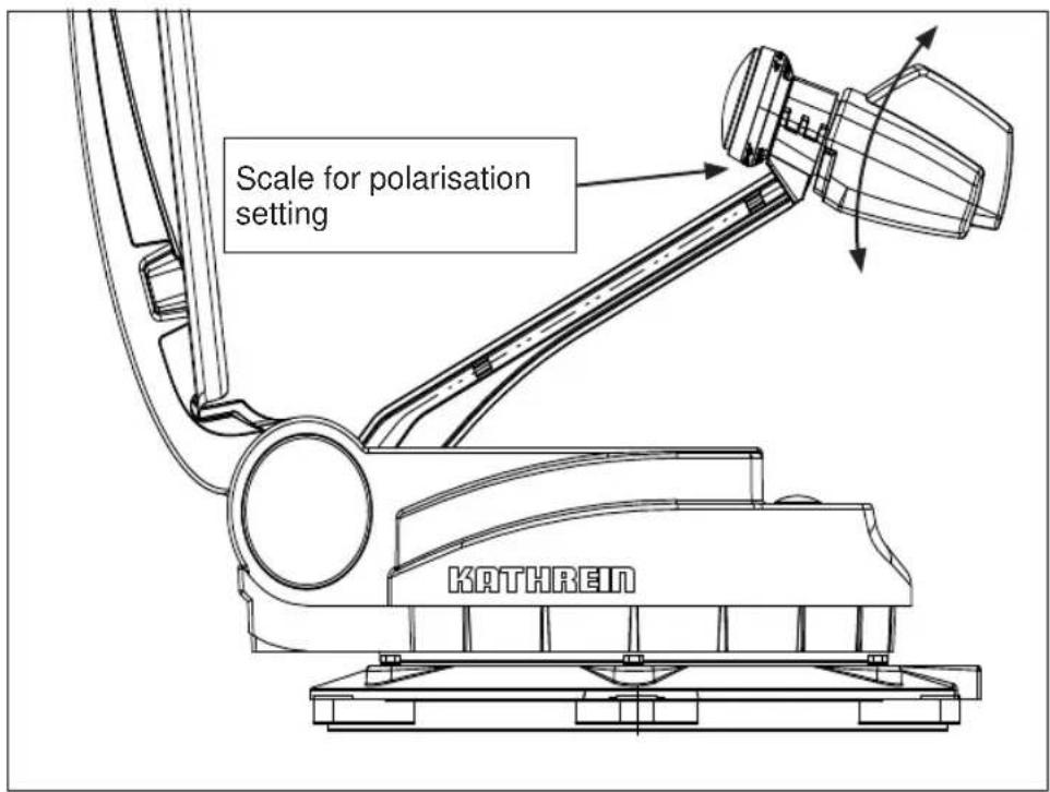
- Tighten the hexagon socket screw to a torque of 3.3-3.5 Nm.
- Leave the installation location and reconnect the UFS 940sw to the power supply.
- Switch the receiver on firstly with the main switch and then with any of the numeric buttons.
The CAP 720 is now ready to use.
POLARISATION SETTING
View after installation +45° View after installation -45°


MANUAL LOWERING TO PARK POSITION

If a defect arises in the electronic controls, after some disassembly work the antenna can be returned to the park position (horizontal position) manually. Following this however recalibration by an authorised workshop is always necessary.
Driving to the nearest workshop with the antenna extended at a moderate speed and taking into account the increase + 79 cm in the vehicle height is an option and is preferable to manual lowering!
Users unfamiliar with the necessary repair work are urged not to attempt to lower the antenna manually into park position themselves. They should contact a technician or engineer. They may find a suitable person on the campsite.
In any case, the safety instructions listed below must be followed.
SAFETY INSTRUCTIONS



Make sure that:
- The antenna and connected units are disconnected from the power
- The person carrying out the repair does not suffer from vertigo and can move around safely on the roof of the caravan or motor home
- The person carrying out the repairs is wearing sturdy and non-slip shoes
- The person carrying out the repairs has a secure position to stand and hold on while working
- The roof and the climbing equipment used (e.g. ladder) are dry, clean and non-slip
- The roof can withstand the weight of the person carrying out the repairs
Attention! Risk of death or injury due to falling or roof collapsing!
- Do not hold onto the antenna, as the rocker comes free without warning during dismantling
Attention! Risk of death and injury due to falling or crushing!
- Nobody should be inside the caravan/motor home underneath the antenna during dismantling/installation
Attention! Risk of death or injury due to possible roof collapsing and falling parts!
MANUAL LOWERING TO PARK POSITION
MANUAL LOWERING


- In the centre of the antenna (arrowed) there is a plastic cap. Lever this off with a narrow slot-head screwdriver.
- Behind the cap is an M8 hexagon head screw. Unscrew these using a 13 mm socket wrench.
After removing the M8 screw, a further thread can be seen.
-
Attention! Secure and support the antenna to prevent it tipping over. The connection to the rocker can suddenly come loose during the next step (item 4). It is then no longer connected to the turntable!
-
Screw an M10 x 40 screw into this thread (minimum length: 40 mm). Screwing in the M12 screw pushes the rocker off the taper seating on the tapered shaft and releases the engagement.
Attention: Screw the screw in only as far as necessary to free the rocker from engagement on the tapered shaft!
- Tilt the antenna to the park position (horizontal position).
- Remove the M12 screw 1 . This allows the rocker to re-engage on the tapered shaft.
- Replace the M8 screw and tighten it.
- Replace the plastic cap.
Loosening the rocker from the taper shaft causes the rocker zero point position to be lost. When the authorised dealer rectifi es the defect he will recalibrate the rocker!
- Consult an authorised dealer.
*) Earlier versions used an M10 screw instead of an M12 screw
TECHNICAL SPECIFICATION
DIMENSIONS (MM)

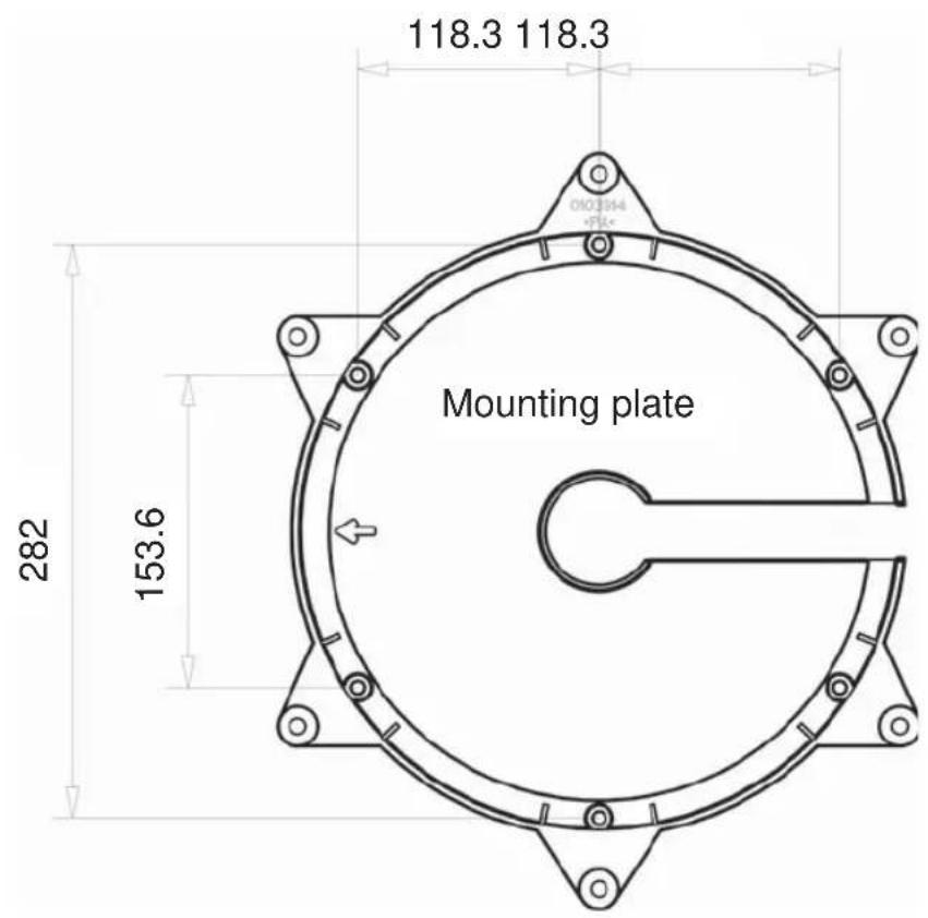
TECHNICAL SPECIFICATION

TECHNICAL SPECIFICATION
| Type CAP 720 | ||
| Part no. 20310023 | ||
| LNB | 2 switchable outputs: V/H (14/18 V) low/high (0/22 kHz) | |
| Supply voltage LNB V | vertical: 11.5-14 horizontal: 16-19 | |
| Input frequency GHz 10.70-12.75 | ||
| Output frequency | MHz | 950-1950/1100-2150 |
| Oscillator frequency (L.O.) | GHz | 9.75/10.60 |
| System quality (G/T) 11.3/12.5 GHz | dB/K | 13.4/13.7 |
| Power supply (vehicle battery) | V | 10.9-13.8 |
| Power consumption from the 12 V vehicle electrical system: Inrush current Satellite search TV reception Stand-by | A | Type 10, max. 12 typ. 3 typ. 1.2 typ. 0.024 |
| Current consumption from the receiver | mA | typ. 160 |
| Setting range: Elevation Azimuth Skew | ° | 0-75 370 ± 45 |
| Weight of the turntable with parabolic reflector | kg | 9.7 |
| Packing unit/weight | pc./kg | 1/15.3 |
Ignition signal 12...24 V
Search time for fi rst satellite (typ.) 10...120 s
Search time for further satellites (typ.) 2...30 s
Search time for LSM 2...15 s
(LSM = Last Satellite Memory)
Safety Data Sheet
Conforms to Regulation (EC) No. 1907/2006 (REACH), Annex II - United Kingdom (UK)

1. IDENTIFICATION OF THE SUBSTANCE/PREPARATION AND OF THE COMPANY/UNDERTAKING
Identification of the substance/preparation
Product name or Trade name :
Sikaflex®-291i
Use of the substance/preparation : Chemical product for construction and industry
Company/undertaking identification
Manufacturer/Distributor
: Sika Limited
Watchmead Welwyn Garden City
Hertfordshire. AL7 1BQ
United Kingdom
Telephone no.
: 01707 394444
Fax no.
: 01707 329129
e-mail address of person
: EHS@uk.sika.com
responsible for this SDS
Emergency telephone number
: +44 (0)1707 363899 (available during office hours).
2. HAZARDS IDENTIFICATION
The product is not classified as dangerous according to Directive 1999/45/EC and its amendments.
Additional warning phrases
: Contains isocyanates. See information supplied by the manufacturer. Contains Sika Hardener LH (1,6-Hexanedialdimine), Pentamethyl piperidylsebacate. May produce an allergic reaction.
See section 11 for more detailed information on health effects and symptoms.
3. COMPOSITION/INFORMATION ON INGREDIENTS
Chemical family/
: Filled reactive PUR-polymer
Characteristics
There are no ingredients present which, within the current knowledge of the supplier and in the concentrations applicable, are classified as hazardous to health or the environment and hence require reporting in this section.
4. FIRST AID MEASURES
First-aid measures
| Inhalation | : Get medical attention if symptoms occur. |
| Ingestion | : Do not induce vomiting unless directed to do so by medical personnel. Maintain an open airway. Seek immediate medical attention. |
| Skin contact | : Flush contaminated skin with plenty of water. Remove contaminated clothing and shoes. Get medical attention if symptoms occur. |
| Eye contact | : Immediately flush eyes with plenty of water, occasionally lifting the upper and lower eyelids. Check for and remove any contact lenses. Continue to rinse for at least 10 minutes. Get medical attention. |
| Notes to physician | : No specific treatment. Treat symptomatically. Contact poison treatment specialist immediately if large quantities have been ingested or inhaled. |
See section 11 for more detailed information on health effects and symptoms.
Date of issue
: 02.12.2010.
MSDS no. : 131725
1/5
Sikaflex®-291i
02.12.2010 2/5
5. FIRE-FIGHTING MEASURES
Extinguishing media
| Suitable | : Use an extinguishing agent suitable for the surrounding fire. |
| Not suitable | : None known. |
| Special exposure hazards | : In a fire or if heated, a pressure increase will occur and the container may burst. |
| Hazardous combustion products | : Decomposition products may include the following materials:carbon dioxidecarbon monoxidehalogenated compoundsmetal oxide/oxides |
| Special protective equipment for fire-fighters | : Fire-fighters should wear appropriate protective equipment and self-contained breathing apparatus (SCBA) with a full face-piece operated in positive pressure mode. |
6. ACCIDENTAL RELEASE MEASURES
| Personal precautions | : Keep unnecessary and unprotected personnel from entering. Do not touch or walk through spilt material. Put on appropriate personal protective equipment (see section 8). |
| Environmental precautions | : Avoid dispersal of spilt material and runoff and contact with soil, waterways, drains and sewers. Inform the relevant authorities if the product has caused environmental pollution (sewers, waterways, soil or air). |
| Large spill | : Stop leak if without risk. Move containers from spill area. Prevent entry into sewers, water courses, basements or confined areas. Contain and collect spillage with non-combustible, absorbent material e.g. sand, earth, vermiculite or diatomaceous earth and place in container for disposal according to local regulations (see section 13). |
| Small spill | : Stop leak if without risk. Move containers from spill area. Absorb with an inert material and place in an appropriate waste disposal container. |
7. HANDLING AND STORAGE
| Handling | : Put on appropriate personal protective equipment (see section 8). Eating, drinking and smoking should be prohibited in areas where this material is handled, stored and processed. Workers should wash hands and face before eating, drinking and smoking. Avoid contact with eyes, skin and clothing. Keep in the original container or an approved alternative made from a compatible material, kept tightly closed when not in use. |
| Storage | : Store in accordance with local regulations. Store in original container protected from direct sunlight in a dry, cool and well-ventilated area, away from incompatible materials (see section 10) and food and drink. Keep container tightly closed and sealed until ready for use. Containers that have been opened must be carefully resealed and kept upright to prevent leakage. Do not store in unlabelled containers. Use appropriate containment to avoid environmental contamination. |
| Packaging materials | |
| Recommended | : Use original container. |
8. EXPOSURE CONTROLS/PERSONAL PROTECTION
Exposure limit values
Date of issue
: 02.12.2010.
MSDS no. : 131725
2/5
Sikaflex®-291i
02.12.2010 3/5
- EXPOSURE CONTROLS/PERSONAL PROTECTION
| Ingredient name | Occupational exposure limits |
| No exposure limit value known. | |
| Recommended monitoring procedures | : If this product contains ingredients with exposure limits, personal, workplace atmosphere or biological monitoring may be required to determine the effectiveness of the ventilation or other control measures and/or the necessity to use respiratory protective equipment. Reference should be made to European Standard EN 689 for methods for the assessment of exposure by inhalation to chemical agents and national guidance documents for methods for the determination of hazardous substances. |
| Exposure controls | |
| Occupational exposure controls | : Good general ventilation should be sufficient to control worker exposure to airborne contaminants. If this product contains ingredients with exposure limits, use process enclosures, local exhaust ventilation or other engineering controls to keep worker exposure below any recommended or statutory limits. |
| Hygiene measures | : Wash hands, forearms and face thoroughly after handling chemical products, before eating, smoking and using the lavatory and at the end of the working period. Appropriate techniques should be used to remove potentially contaminated clothing. Wash contaminated clothing before reusing. |
| Respiratory protection | No special measures required. |
| Hand protection | : Chemical-resistant, impervious gloves complying with an approved standard should be worn at all times when handling chemical products if a risk assessment indicates this is necessary. Recommended: Butyl rubber/nitrile rubber gloves. |
| Eye protection | Safety eyewear complying with an approved standard should be used when a risk assessment indicates this is necessary to avoid exposure to liquid splashes, mists, gases or dusts. |
| Skin protection | : Personal protective equipment for the body should be selected based on the task being performed and the risks involved and should be approved by a specialist before handling this product. Recommended: Use barrier skin cream. |
| Environmental exposure controls | : Emissions from ventilation or work process equipment should be checked to ensure they comply with the requirements of environmental protection legislation. In some cases, fume scrubbers, filters or engineering modifications to the process equipment will be necessary to reduce emissions to acceptable levels. |
9. PHYSICAL AND CHEMICAL PROPERTIES
General information
Appearance
| Form | : Paste. |
| Colour | : Various. |
| Odour | : Faint odour. |
| Important health, safety and environmental information | |
| Flash point | : Closed cup: >150°C (>302°F) |
| Density | : ~1.34 g/cm 3 [20°C (68°F)] |
| Solubility | : Insoluble in the following materials: water |
- STABILITY AND REACTIVITY
| Stability | : The product is stable. |
| Conditions to avoid | : No specific data. |
| Materials to avoid | : No specific data. |
| Hazardous decomposition products | : Under normal conditions of storage and use, hazardous decomposition products should not be produced. |
Date of issue
: 02.12.2010.
MSDS no. : 131725
3/5
Sikaflex®-291i
02.12.2010 4/5
11. TOXICOLOGICAL INFORMATION
Potential acute health effects
| Inhalation | : May cause irritation. |
| Ingestion | : Can cause gastrointestinal disturbances. |
| Skin contact | : May cause skin irritation. |
| Eye contact | : May cause eye irritation. |
| Chronic effects | : No known significant effects or critical hazards. |
12. ECOLOGICAL INFORMATION
Environmental effects
: Avoid contact of spilt material and runoff with soil and surface waterways. Do not empty into drains; dispose of this material and its container in a safe way.
13. DISPOSAL CONSIDERATIONS
| Methods of disposal | : The generation of waste should be avoided or minimised wherever possible. Empty containers or liners may retain some product residues. This material and its container must be disposed of in a safe way. Dispose of surplus and non-recyclable products via a licensed waste disposal contractor. Disposal of this product, solutions and any by-products should at all times comply with the requirements of environmental protection and waste disposal legislation and any regional local authority requirements. Avoid dispersal of spilt material and runoff and contact with soil, waterways, drains and sewers. |
| European waste catalogue (EWC) | : 08 04 10 waste adhesives and sealants other than those mentioned in 08 04 09 |
| Packaging | : Completely emptied packaging or practically empty packaging containing dried/cured residues, once relieved of all pressure can be disposed of as non-hazardous waste.Packaging may still contain hazardous residues and disposal should undertaken by a licensed waste contractor.Any disposal practice must be in compliance with local and national laws and regulations.15 01 10* packaging containing residues of or contaminated by dangerous substances |
14. TRANSPORT INFORMATION
International transport regulations
ADR
Not regulated.
IMDG
Not regulated.
Marine pollutant : No
IATA
Not regulated.
Date of issue
: 02.12.2010.
MSDS no. : 131725
4/5
Sikaflex®-291i
02.12.2010 5/5
15. REGULATORY INFORMATION
EU regulations
Classification and labeling have been determined according to EU Directives 67/548/EEC and 1999/45/EC (including amendments) and take into account the intended product use.
Additional warning phrases : Contains isocyanates. See information supplied by the manufacturer. Contains Sika Hardener LH (1,6-Hexanedialdimine), Pentamethyl piperidylsebacate. May produce an allergic reaction.
VOC content (EU) : VOC (w/w): 0%
National regulations
Regulatory information : Chemicals (Hazard Information and Packaging for Supply) Regulations 2009 (CHIP 4)
Control of Substances Hazardous to Health Regulations 2002 (COSHH) (as amended)
Health & Safety at Work Act 1974
The Environmental Protection (Duty of Care) Regulations 1991
Hazardous waste regulations 2005
The Carriage of Dangerous Goods and Use of Transportable Pressure Equipment Regulations 2007
Guidance Publications : Approved Code of Practice - Management of Health and Safety at Work, HSE General Approved Code of Practice to COSHH Regulations, HSE.
16. OTHER INFORMATION
History
Date of printing : 02.12.2010.
Date of issue : 02.12.2010.
Date of previous issue : No previous validation.
Indicates information that has changed from previously issued version.
Notice to reader
The information contained in this Safety Data Sheet corresponds to our level of knowledge at the time of publication. All warranties are excluded. Our most current General Sales Conditions shall apply. Please consult the product data sheet prior to any use and processing.
Date of issue
: 02.12.2010.
MSDS no. : 131725
5/5
Technical data sheet
Version 3 (09/2011)
Sikaflex®-291i
The strongly bonding marine adhesive
TechnTechnical characteristics
| Chemical basis | 1-component |
| Colour | white, black, grey wood |
| Curing mechanism | cures by absorbing |
| Density before curing (DIN 53479) | approx. 1.3 kg/l, depending on colour |
| Stability | good |
| Processing temperature | +10°C to +40°C |
| Skin formation time 1 | approx. 60 min |
| Through-curing speed | (see diagram 1) |
| Volume change (DIN 52451) | approx. 2% |
| Shore A hardness (ISO 868 / DIN 53505) | approx. 40 |
| Tensile strength (ISO 527 / DIN 53504) | approx. 1.8 N/m 2 |
| Elongation at break (ISO 527 / DIN 53504) | approx. 500% |
| Tear propagation resistance (ISO 34 / DIN 53515) | approx. 7,0 N/mm |
| Glass transition temperature (ISO 4663 / DIN 53445) | approx. -45 °C |
| Operating temperature short-term | sustained 4 hours 1 hour |
| Storage life (storage at less than 25°C in unopened containers) | 12 months |
1) 23°C / 50% r.Lf.
Description
Sikaflex ® 291i is a stablesingle-component polyurethane sealant developed for boatbuilding. On exposure to atmospheric humidity it cures to an elastomer.
Sikaflex ® 291i satisfies the fire protection requirements of the International Maritime Organisation (IMO).
Sikaflex® 291 is manufactured in accordance with the ISO 9001/14001 Quality Assurance System and the Responsible Care Programme.
Product advantages
- Wheelmark approved
- 1-component
- highly resilient
- low odour
- non-corrosive
- can be painted over
- broad bonding spectrum
- VOC-free and emissions-free
Application Range
Sikaflex® 291i is a product widely use in shipbuilding and boatbuilding for creating resilient and vibration-resistant sealing joints in internal and external areas. Sikaflex® 291i has strong bonding properties to the principal materials used in shipbuilding. Suitable substrates include wood, metals, primed and paint surfaces (2-component system), ceramic materials, plastics (UP-GRPs etc.).
Sikaflex® 291i should not be used for sealing plastics liable to crackunder stress (such as PMMA, PC etc). This product is suitable only for use by experienced persons. In order to check the bonding and materialcompatibility, preliminary trials with original substrates under actual production conditions are recommended.


Sikaflex ns -291i 1 / 2
Curing mechanism
The cross-linking reaction of Sikan eX-291i is triggered by atmospheric humidity. At lower temperatures the water content of the air is less and the cross-linking reaction proceeds somewhat more slowly (see diagram 1).
![| Zeit [Tage] | Layer thickness (mm) | | ----------- | -------------------- | | 0 | 2 | | 2 | 4 | | 4 | 6 | | 6 | 8 | | 8 | 10 | | 10 | 11 | | 12 | 12 | | 14 | 12 | | 16 | 12 | | 18 | 12 | | 20 | 12 | | 22 | 12 | | 24 | 12 | | 26 | 12 | | 28 | 12 | | 30 | 12 | | 32 | 12 | | 34 | 12 | | 36 | 12 | | 3…](/content/2026/05/778618/images/f65e0d5a75def16d298979f4720f4d854b5184d0b9d4c7bfe7f757d2d6646e85.jpg)
Diagram 1: Through curing speed of Sikarex® 291
Chemical Stability
Sikaflex ® -291i is resistant to water, seawater, lime water and sewage, plus dilute acids and alkalis. It is resistant for a short time to fuels, mineral oils and vegetable and animal greases and oils. It is not resistant to organic acids, alcohol, concentrated mineral acids and alkalis, and solvents.
This information is only for general reference. Advice for specific applications is available on request.
Processing instructions
Substrate preparation
The surfaces to be bonded must be clean, dry, and free of dust and grease. Bonding can be improved by wiping over the surfaces to be bonded with a Sika bonding promotion agent. Data on preparation of the material surfaces can be found in the Sika ® pre-treatment table for marine applications.
Processing
Cut off the tip of the nozzle to suit the crack to be filled and apply the sealant with a suitable manual, battery-powered or pneumatic piston gun into the crack, leaving no air bubbles. The processing temperature must not be below 10°C nor above 40°C. The optimum temperature of the sealant and materials is between 15°C and 25°C.
Smoothing off
Smoothing off must be performed within the skin formation time of the adhesive. We recommend Sika® N smoothing off agent. Other smoothing off agents must be checked for suitability before use.
Removal
Uncured Sikaflex®-291i can be removed from equipment and tools with Sika® Remover 208. Cured material can only be removed mechanically. Hands/skin should be cleaned immediately with Sika® Handclean or a suitable hand cleansing paste and water. Do not use solvents!
Painting over
Sikaflex®-291i can be overpainted with most 2-component paint systems. Paint compatibility must be checked by preliminary trials under actual production conditions. If the paint is heat-cured, the sealant must first be fully cured. Since the resilience of the paint is less than that of the adhesive/sealant, the paint may crack in the region of the joint. Paints based on PVC and paints that cure by oxidation (oil-based and alkydresin paints) are unsuitable for painting over Sikaflex®-291i.
For further
The following documents are available on request:
Safety data sheet
Sika® pre-treatment table for marine applications
General guidelines for working with
Sikaflex ® adhesives and sealants
Marine handbook
Containers
| Tube | 100 |
| Cartridge | 300 |
| Bag | 600 |
Note on measured values
All the technical values stated in this data sheet are based on laboratory trials. Values measured in practice may vary from these due to circumstances beyond our control.
Health and safety provisions
When handling our products, refer to the relevant physical, safety, technical toxicological and ecological data in the specific safety data sheets for the material. The applicable regulations, such as the hazardous substances regulations should be complied with. On request we will send you our system data sheet TM 7510 "Instructions for protection at work" for handling Sika Deutschland GmbH products.
Note:
The details above, especially the suggestions for the processing and use of our products are based on our knowledge and experience in normal cases, providing the products are correctly stored and applied. Due to the variety of materials, surfaces and variations in working conditions, no guarantee of a work product or liability from any legal relationship can be founded on these instructions or on oral advice unless we are charged with premeditated or gross negligence. Here the user must prove that he brought to Sika's attention promptly, completely and in writing all knowledge necessary for Sika to make an objective assessment of expectation of success. It is the user's responsibility to check the products for suitability for the intended application. We reserve the right to change the product specifications. The industrial rights of third parties must be respected. In all other respects our respective sales and delivery conditions apply. The latest version of the technical data sheet is applicable and should be requested from us.
Fur further
Internet: www.sika.de, E-Mail: industry@de.sika.com
The operating manual for the
CAP 720
If, despite studying this operating manual, you still have questions about getting started with the unit or using it correctly, or if unexpected problems occur, please contact your specialist dealer.
The Kathrein Technical Customer Support is also at your disposal. Tel: +49 8031 184-700

The automatic overnight updating of the EPG data described in the UFS 940sw operating manual is not performed automatically when the UFS 940sw is being operated on the CAP 720! The EPG data are updated when an individual channel is viewed. At this point however the receiver updates all EPG data for the channels that are broadcast from the currently selected receiving transponder.
For example: You have selected the channel "SAT.1". At this point for instance the EPG data will be updated for "ProSieben" and "KABEL1".
IMPORTANT INFORMATION FOR CAP 720 BEFORE SETUP

This section of the UFS 940sw operating manual for the turntable assumes that the UFS 940sw and the turntable have been properly installed and connected, as described in the installation and operating manuals!
If you have not yet done so, read the safety instructions at the beginning of the UFS 940sw operating manual and follow them when handling the UFS 940sw and the turntable unit!

Before setting up your satellite system, make sure that the location allows a free view to the satellite positions to the South and is not shadowed by trees or other obstructions. This will save you time and effort!

So as to avoid overheating the turntable motors, do not operate the motors continuously for longer than 20 minutes.
None of the search procedures initiated by the CAP 720 will require as much as 20 minutes operation. Only repeated unsuccessful search procedures or manual overrides by the user can cause this limit to be exceeded.

As soon as the ignition signal is no longer present at the turntable, if the receiver is switched on the turntable will be supplied with a +12 V power supply and may automatically move to the last known satellite position. Therefore switch your receiver on only if you wish to use your CAP 720.

REMOTE CONTROL
All settings on the UFS 940 are made using the remote control!
FIRST INSTALLATION

Before using your unit for the first time, read the "Safety Instructions - Important Information" and "Installation and Connection" sections.
You will find a sample configuration for a motor home in the Section "Installation and connection", "Connection Example".
Do not connect the unit to the power supply until all installation work has been properly carried out.
The guidance given in the “First Installation” section assumes that the receiver has been properly connected, as per the “Safety Instructions - Important Information” and “Installation and Connection” sections.
First switch your TV set on and select the AV or video/HDMI channel number to which you have connected the receiver. Switch on your receiver at the power switch on the rear of the unit. The following display appears:
Also note the bars at the bottom of the on-screen display! These provide information on what to do next.

Select the menu language you want using the ▲▼ buttons. Available options: German, English, French, Italian, Spanish, Czech, Dutch, Polish, Norwegian, Turkish and Russian.
Press the 📄 (green) button to move to the next menu.
Note: If you are unsure whether you chose the right option from a previous menu, you can go back a step at any time during the first installation process by pressing the (red) button.
FIRST INSTALLATION
The following display appears:
Use the ▶▶ buttons to select whether to replace the factory pre-programmed channel list by a pre-sorted channel list for a specific country (at present only a limited number of pre-sorted channel lists are available). If you prefer to use the factory pre-programmed channel list, choose "No" under "Restore Channellist".

Press the PIP (green) button to move to the next menu.
The following display appears:
Use the 📄 buttons here to select the basic settings for the video and audio output from the receiver to the TV set.
For this, refer to the operating manual for your TV set and take care to select only those settings that your TV set can process.

Video Output via
Select the connection on the receiver to which you have connected your television. Either
HDMI

or
VIDEO

Note: The better picture quality, in particular for HDTV signal is obtained via the HDMI port. The precondition for this however is that your TV set has a HDMI port.
HDMI Format
Here you can select the picture resolution that will be sent to your TV set. Either
- 1080i (resolution 1920 x 1080, half-screen images)
- 576p (resolution 720 x 576, full-screen images) or
- 720p (resolution 1280 x 720, full-screen images)
- automatically
TV Format
Here you can select the TV picture format. Either
- 4:3 or
- 16:9
FIRST INSTALLATION
Show 4:3 event
Here you can select the type of screen display mode for 4:3 broadcasts on a 16:9 TV set:
- normal (pillarbox)
- Stretched (Full Screen) or
- zoom in (Pan & Scan)
Audio format via HDMI
Here you can select the type of audio signal that is transmitted by the HDMI interface. Select the signal that your TV set can process:
- Decoded PCM or
- S/PDIF format
TV standby via HDMI
If you select "Off", the TV set must be switched on or off separately. If you select "On", the TV set will be switched on automatically as the receiver starts up (but only if the TV set was in stand-by mode). If the receiver is switched off into stand-by mode, the TV set will also be switched to stand-by mode.
Automatically switching the TV set on/off by the receiver is available only if the TV set supports this function!
Picture format
Select the type of screen display, depending on your setting for the TV format:
- TV aspect ratio "4:3": Pan & Scan or Letterbox
- TV aspect ratio "16:9": Always 16:9 or automatic
Television System
Here you can select the TV standard you wish to use.
- PAL or
- NTSC or
- MULTI
Press the 📄 (green) button to move to the next menu.
The following display appears:

System
Use the ▶▶ buttons here at "System" to select "CAP". Then use the ▲▼ buttons to select the "Initialize CAP" line and press the OK button to confirm.
FIRST INSTALLATION
Your CAP system will then be initialised. You will then see the following display:

Press the ☐ (green) button to move to the next menu. The following display appears:
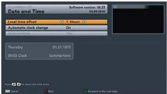
Local time offset (UTC)
Here you can use the ▶▶ buttons to select the local time offset to UTC (formerly GMT) (e.g. for Germany: +1 hour). You can set the offset in 1 hour steps. The maximum offset is 12 hours (+ and -).
Automatic clock change (summer/winter time)
Use the ▶▶ buttons to select whether the receiver should automatically change over to and from summer and winter time. If “On” is selected, the receiver automatically sets itself to the right time. If you select the setting “Off”, you must make the change to and from summer time manually by setting the “Summertime” fi eld to “Yes” or “No”.
When you have completed all settings, press the (green) button, to complete the first installation.
CAP MENU (TURNTABLE ANTENNA SETTINGS)
CALLING UP THE CAP MENU
Press the ☐ (green) button. The following display appears:
Use the ▲▼ buttons to select the "Antenna Confi guration" line and press the OK button to confi rm.
The following display appears:
You can also call up this menu via the main menu "Settings", "Antenna Configuration" (System: CAP).
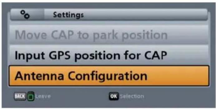

RESETTING THE CAP SYSTEM (TURNTABLE ANTENNA) (RESET)

All satellite positions found by a search will be deleted.
Use the ▲▼ buttons to select the "Reset turn table antenna" line and press the OK button to confirm. The following display appears:

Press the OK button to confirm, or the BACK button to cancel.
Note: Before exchanging any component of the system (such as the receiver) the turntable should be moved to its park position by means of the "Reset turn table antenna" command. The "Reset" deletes all previously saved satellite positions. The satellite data in the UFS 940sw receiver are however retained.
CAP MENU (TURNTABLE ANTENNA SETTINGS)
INPUTTING THE CAP GPS POSITION
You can use these functions to prevent long CAP search times for the saved satellites, for instance after you have changed location. Inputting the GPS data for your present position allows the CAP unit to find the desired satellite in a fraction of the time.
Use the ▲▼ buttons to select the "Input GPS position for CAP" line and press the OK button to confirm. The following display appears:

The GPS data can be input using the numeric keys and/or the ▶▶ buttons. When you have input all the data, press the OK button to confirm, or the BACK button to cancel. These coordinates are retained even after CAP has been reset.
TO MOVE THE ANTENNA MANUALLY

This function should be used only by experienced users. Exact knowledge of the satellite position and your present location are necessary when aligning the antenna manually to a satellite. Watch out for any obstacles that the antenna might collide with. The antenna is liable to be damaged by such collisions!
You can set the inclination and horizontal angle of the antenna using the "Elevation" and "Move to the azimuth (rotate the antenna)" commands. Check your settings by reference to the "Signal-Strength" and "Signal-Quality" bars on the right-hand side. The taller the bar, the stronger the signal received and the better its quality.

The currently displayed position of the CAP is the "park position".
CAP MENU (TURNTABLE ANTENNA SETTINGS)
ELEVATION
Using the numeric keys and/or the ▶ buttons, input the desired elevation value.
Two seconds after completion of the input or when the OK button is pressed, the CAP moves to the selected position.
LNB TILT/SKEW
This function is not available on the CAP 720.
STOP ON SIGNAL
Use the ▶▶ buttons to select whether the CAP should stop automatically (Yes or No) on detection of a satellite signal during manual alignment by the user.
MOVE TO THE AZIMUTH (ROTATE THE ANTENNA)
As soon as you switch the orange bar to the "Move to the azimuth (rotate the antenna)" line you will see the following display:
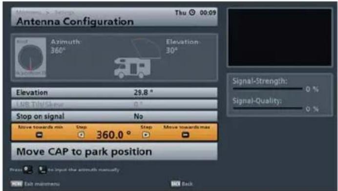
You now have the following options for rotating your CAP:
- "Step by step" using the ▶ buttons
- "Move towards min" (minimum rotary position) with the button or
- "Move towards max" (maximum rotary position) with the ➤ button
Note: If you previously set "Stop on signal" to "Yes", the antenna will stop as soon as it detects a satellite signal.
CAP MENU (TURNTABLE ANTENNA SETTINGS)
MOVE CAP TO PARK POSITION
Press the OK button; the CAP will move to the park position. As soon as the turntable reaches the park position, the following display appears:
CAP SETTINGS

This menu allows important basic settings for the CAP, such as the elevation offset to be set. These two settings in particular should be performed by a specialist to match your needs and the conditions; if they are set incorrectly the CAP may be damaged!
Use the ▲▼ buttons to select the "CAP settings" line and press the OK button to confirm. The following display appears:

ELEVATION OFFSET
Neither of these settings should be changed unless the change is necessary because of neighbouring
roof structures or other obstacles. The settings are made using the cursor buttons (☐) or the numeric keys.
SEARCH SPEED
In the fringe areas of the satellite footprints it may happen that a better search result is obtained by using a lower CAP search speed. If the “Regular” search speed does not give satisfactory search results, you can reduce the search speed to “Slow”.
If the signal strength and quality are good however you can set search speed to "Quick". Normally we recommend the search speed is set to "Regular".
Make the settings using the ▶ buttons.
ALIGNMENT (SATELLITE SEARCH)
The antenna is aligned automatically. After the UFS 940sw has been switched on, the turntable automatically moves to the last channel received and the associated satellite position (e.g. ARD/ASTRA). This works because each satellite is automatically recognised by the turntable.
The satellite search is started when you select a channel. If the turntable has not yet saved the position of the satellite, you will see the following display when you select a channel (example):

If the vehicle is not on supports during the search process and people are moving around inside it, there is a risk that movement of the vehicle will mean that the satellite is not found.
You will see this display if the CAP has not yet saved a satellite position (e.g. after the CAP has been reset or during the First Installation).
You will see this display if the CAP has already saved a satellite position but because for instance the location of the vehicle has changed, the satellite is no longer to be found at the known/saved position.


The search starts automatically after five seconds or if the OK button was pressed previously. The search may take a few minutes. You will first see the following message:
The search time will be reduced if you input the GPS coordinates (see „CAP menu (motorised antenna settings)“, „Inputting the CAP GPS position“).

As soon as the turntable has found the correct satellite, it saves this position. During this process you receive no TV picture. The turntable will then perform an automatic fine adjustment (if the signal level is sufficient, the satellite position will be saved immediately by the turntable). During the fine adjustment you will for the first time receive a TV picture, this however can still “freeze” during the fine adjustment process - whether it does or not is system-dependent.
The set position (of the satellite that was found) is saved and the desired channel appears on the TV screen.
CHANNEL (SATELLITE) SELECTION/PROGRAMMING THE TIMER
By pressing the + - buttons all channels can be selected in the sequence that they appear in the current channel list and its sorting. Press the TVR (blue) button to switch between TV and radio channels.
CHANNEL SELECTION FROM THE CHANNEL LIST
Providing you are not in a menu, pressing the OK button calls up the channel list. The following display appears:

When you open this list the channel list selection/sort order is displayed from where you selected the last channel.
For instance you can use the ←→ buttons to display various channel lists sorted by satellite (e.g. ASTRA 19.2° or Hotbird 13°).
The cursor buttons ( ) are used to navigate within the respective channel list view to select the desired channel. The selection of the desired channel is confirmed by pressing the OK button. As soon as the turntable has found the satellite or has reached the known position, you will now hear and
CHANNEL (SATELLITE) SELECTION/PROGRAMMING THE TIMER
view the currently selected channel in the small window at the top right. To exit the channel list and return to the TV picture, press the OK button again, or press the BACK button.
Note:
A comprehensive explanation of the channel list with its detailed functions (e.g. the scan and sort function) can be found in the UFS 940sw operating manual.
CHANNEL SELECTION FROM THE CHANNEL LIST (SORTED BY SATELLITE)
To view the channel list sorted by the saved satellites, proceed as follows. Press the OK button (starting from the TV picture). If the “green view” does not appear in the complete list, press the PIP (green) button.
Now use the ▶▶▶ buttons to select the desired satellite. You will automatically see the channel list stored for the satellite (see example):
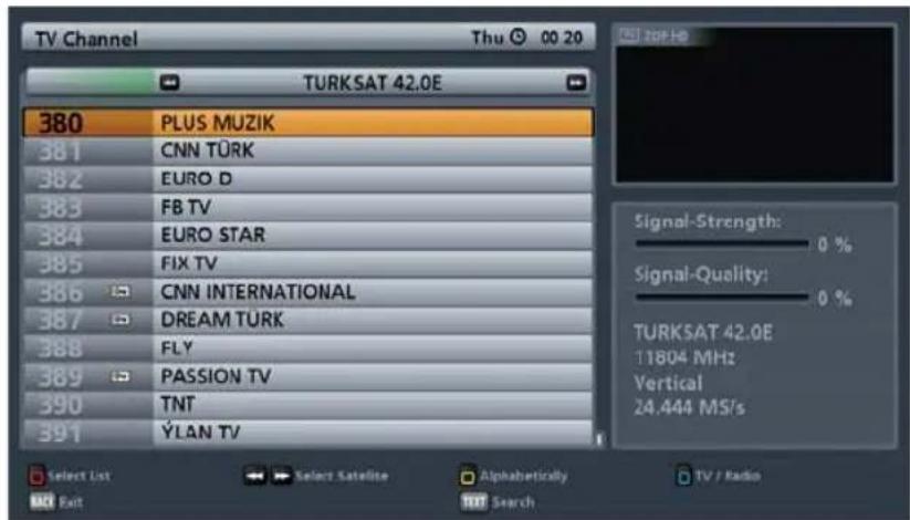
The channel selection functions as previously described "Channel selection from a channel list".
TIMER PROGRAMMING
See the UFS 940sw operating manual for details of how to program the timer. When using the UFS 940sw on a CAP 720 please note the following additional instruction:

To prevent the turntable rotating at a time when it is unsupervised or when rotation might be irritating (e.g. in the middle of the night), a timer can be set. During the timer period the turntable is active only if the UFS 940sw is in operation or is in standby mode.
If the receiver is completely switched off (switched off at the power socket) and/or the turntable is in park position, the turntable will be inactive during the timer period! The same applies if during the first movement the satellite position is not found.
CHANGE OF LOCATION
After a change of location, the antenna moves to the last position selected. After initialisation, you will therefore see the following display (example, as it depends on the last selected position):
For slight changes of location, the antenna can find the satellite very quickly.
If the satellite is not found at the known position, the search starts automatically.

If the search is unsuccessful, the following message appears:

Note:
If you know the GPS data for your new location, refer to the item "Inputting the CAP GPS position" in the section "CAP menu (turntable antenna settings)". Inputting the GPS data for your current location allows the search times for your turntable antenna to be reduced.
The search starts automatically after five seconds or if the OK button was pressed previously. The search may take a few minutes. You will first see the following message:
As soon as the turntable has found the correct satellite, it saves this position. During this process you receive no TV picture. The turntable will then perform an automatic fine adjustment (if the signal level is sufficient, the satellite position will be saved immediately by the turntable). During the fine adjustment you will for the first time receive a TV picture, this however can still “freeze” during the fine adjustment process - whether it does or not is system-dependent.
The set position (of the satellite that was found) is saved and the desired channel appears on the TV screen.
PARKING THE TURNTABLE
You have four options for "parking" the antenna.
- The antenna can be moved to park position by pressing the on/off button twice.
- Press the (green) button. Use the ▲▼ buttons to select the "Move CAP to park position" line and press the OK button to confirm.
- Press the ▲ button to return to the main menu. The ▲▼ buttons and OK button allow you to call up the submenus ("Settings", "Antenna Configuration", "to move the antenna manually"). Use the ▲▼ buttons to switch to the "Move CAP to park position" item and press the OK button to park the antenna.
- When the ignition is operated, the antenna automatically moves to the park position! However, for this to happen the green wire of the power supply cable must be connected to the ignition and the turntable connected to the power supply (see "Connection Diagram"). Refer to the detailed instructions for this in the CAP unit installation manual.
The antenna is moved to park position, and this is then confirmed.

SPECIAL MESSAGES FROM THE TURNTABLE
SYSTEM PROTECTION MESSAGES
The following messages are shown on the screen to protect your reception system and the on-board power supply:
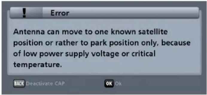
The power supply to the turntable is inadequate (battery voltage below the minimum value). The turntable can still be moved, but communication errors can occur between the UFS 940sw and the turntable (e.g. when scanning for satellites).
If the voltage falls still further, both the following error messages are displayed:
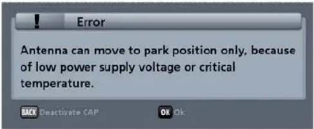
Check the power supply to the turntable and whether it is obstructed (e.g. by a branch). If neither of these causes of faults is displayed, the turntable motor temperature is in the critical range. Allow the turntable to stand for a few minutes in its current position, until the turntable motor temperature has reduced. You can also however move the turntable to the park position and let it cool down there.
Press the OK button and the turntable will move to the park position.

Press the OK button to confirm the displayed message. The turntable cannot be moved any more. Check the power supply to the turntable.
Note: The antenna should not be moved whilst the battery is being recharged, to prevent peak loads when turning on.
SPECIAL MESSAGES FROM THE TURNTABLE

The vehicle ignition was switched on. For safety reasons, the turntable moves into the park position. This operates however only if the green ignition cable for the turntable is connected to the vehicle ignition and the turntable is connected to the power supply! As long as voltage is present at the ignition, the connection to the CAP will remain disabled. This means the CAP cannot be operated.
If the turntable encounters an obstruction, the CAP reverses 10° . This allows the obstacle to be removed more easily.
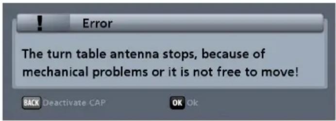
The turntable antenna has reached the mechanical stop or is jammed! Check whether the turntable is obstructed (e.g. by a branch).

The turntable motor temperature is in the critical range. Allow the turntable to stand for a few minutes in its current position, until the turntable motor temperature has reduced.
SPECIAL MESSAGES FROM THE TURNTABLE
MESSAGES ARISING FROM SOFTWARE PROBLEMS

A serious software error has occurred. Reset the turntable in the CAP menu, or contact our service centre.
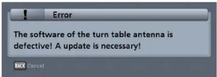
The turntable antenna software is defective. An update is required. Contact our service centre.
FURTHER MESSAGES
The cause of the following error messages may be that the UFS 940 is connected not to the master cable (marked red) but to the slave cable. Please check this first.
This message may also appear if:
- the ignition is switched on
- voltage is present at the ignition cable (green)

The receiver has lost communication with the turntable. Check the connection between the UFS 940sw and the turntable, the power supply and whether possibly the ignition signal is present at the CAP.

The connection to the turntable is defective. Reset the turntable in the CAP menu, check the connections between the turntable and receiver, or contact our service centre.
SPECIAL MESSAGES FROM THE TURNTABLE

The satellite you have selected cannot be received from your current location, or there may have been changes made using the "CAP settings" menu (see section "CAP menu (turntable antenna settings), CAP settings"), as a result of which the desired satellite cannot be received.

You have used the UFS 940sw to program programmes for recording (see timer list view in the UFS 940sw EPG). If you now move the CAP to the park position, your recordings will not be performed.

To prevent the turntable rotating at a time when it is unsupervised or when rotation might be irritating (e.g. in the middle of the night), a timer can be set. During the timer period the turntable is active only if the UFS 940sw is in operation or is in standby mode.
If the receiver is completely switched off (switched off at the power socket) and/or the turntable is in park position, the turntable will be inactive during the timer period! The same applies if during the first movement the satellite position is not found.
CE
The Kathrein-Werke KG hereby confirm that the designated product complies with the following directives on the harmonisation of the laws.
substances in electrical and electronic equipment
Electronic equipment is not domestic waste - in accordance with directive 2002/96/EC OF THE EUROPEAN PARLIAMENT AND THE COUNCIL dated 27 th January 2003 on used electrical and electronic appliances, it must be disposed of properly.
At the end of its service life, take this device for disposal at a designated public collection point.

Spent batteries are special waste!
Do not throw spent batteries into your domestic waste; take them to a collection point for spent batteries!
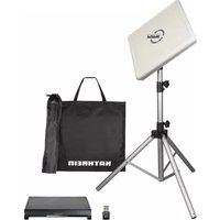
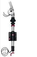


- F
- COMPANY ADDRESS AND ACCREDITED REPRESENTATIVE
- MOBISET 3 TWIN CAP 720 COMPONENTS/SCOPE OF DELIVERY
- SCOPE OF SUPPLY
- CONTENTS (INSTALLATION MANUAL)
- CONTENTS (OPERATING MANUAL)
- CAP 720 OPERATING MANUAL.... 47
- IMPORTANT INFORMATION FOR CAP 720 BEFORE SETUP .... 48
- FIRST INSTALLATION 49
- CAP MENU (TURNTABLE ANTENNA SETTINGS) 53
- ALIGNMENT (SATELLITE SEARCH) 57
- CHANNEL (SATELLITE) SELECTION/PROGRAMMING THE TIMER 58
- CHANGE OF LOCATION.... 60
- SPECIAL MESSAGES FROM THE TURNTABLE 62
- DISPOSAL INSTRUCTIONS.... 67
- PROPER USE
- PROPER USE (USE FOR THE INTENDED PURPOSE)
- THE FOLLOWING CIRCUMSTANCES RESULT IN THE LOSS OF ALL WARRANTY AND LIABILITY CLAIMS TOWARDS THE MANUFACTURER
- NOTE
- THE SYSTEM MAY ONLY BE INSTALLED BY QUALIFIED SPECIALIST PERSONNEL
- SAFETY INSTRUCTIONS - IMPORTANT INFORMATION
- SAFETY DURING INSTALLATION WORK
- MAKE SURE THAT
- CAUTION! RISK OF DEATH OR INJURY DUE TO FALLING OR THE ROOF COLLAPSING
- PROPER INSTALLATION AND SAFETY
- ESSENTIAL INFORMATION
- ADHESIVE SEALANT
- ROAD TRAFFIC LICENSING REGULATIONS (STVZO)
- CABLES
- POWER SUPPLY, FUSING
- CHECKS BEFORE COMMENCING A JOURNEY
- ANTENNA IN THE PARK POSITION WHILST DRIVING
- SAFETY PRECAUTIONS DURING OPERATION
- INSTALLATION AND CONNECTION
- REQUIRED TOOLS AND EQUIPMENT
- UNPACKING AND PREPARATION
- SELECTING THE INSTALLATION LOCATION
- INSTALLATION STEPS
- INSTALLATION OF CABLE GLAND AND MOUNTING PLATE
- INSTALLATION OF TURNTABLE
- VARIANT WITH CABLE GLAND UNDERNEATH THE TURNTABLE
- BRIEF INSTRUCTIONS FOR INSTALLING THE TURNTABLE
- INSTALLATION OF THE UFS 940SW
- SELECTION OF A SUITABLE INSTALLATION LOCATION
- VENTILATION
- CONNECTIONS AND FUSING OF THE UNIT
- PREPARATIONS
- REMOVING THE BLANKING PLUGS
- ATTACHING THE INFRA-RED SENSOR
- IMPORTANT INSTRUCTIONS FOR INSTALLATION
- USE OF OTHER SCREWS
- INSTALLATION
- LAYING CABLES AND CONNECTING THE TURNTABLE
- AVOID LAYING THE CABLES ACROSS SHARP EDGES AND SECURE THE CABLES AGAINST POSSIBLE CHAFING POINTS
- CONNECTING TO THE UFS 940SW
- NOTE THAT THE ANTENNA CAN THEN BE LOWERED ONLY WHEN THE POWER SUPPLY IS PRESENT AT THE TURNTABLE IN ADDITION TO THE IGNITION SIGNAL
- FUNCTIONAL INSTRUCTIONS FOR CONNECTION TO THE ON-BOARD POWER SUPPLY
- CONNECTION EXAMPLE FOR 12 V BATTERY CONNECTION
- RECEPTION RANGE/FOOTPRINT
- DISMANTLING FOR SERVICING
- DISMANTLING
- ADDRESS OF THE SERVICE CENTRE
- FACTORY REPAIR CENTRE REGIONAL REPAIR CENTRE
- ESC
- ELECTRONIC SERVICE CHIEMGAU GMBH
- POLARISATION SETTING
- SAFETY NOTES
- SETTING OPERATIONS
- MANUAL LOWERING TO PARK POSITION
- SAFETY INSTRUCTIONS
- ATTENTION! RISK OF DEATH OR INJURY DUE TO FALLING OR ROOF COLLAPSING
- ATTENTION! RISK OF DEATH AND INJURY DUE TO FALLING OR CRUSHING
- MANUAL LOWERING
- TECHNICAL SPECIFICATION
- SAFETY DATA SHEET
- IDENTIFICATION OF THE SUBSTANCE/PREPARATION AND OF THE COMPANY/UNDERTAKING
- HAZARDS IDENTIFICATION
- COMPOSITION/INFORMATION ON INGREDIENTS
- FIRST AID MEASURES
- FIRE-FIGHTING MEASURES
- ACCIDENTAL RELEASE MEASURES
- HANDLING AND STORAGE
- EXPOSURE CONTROLS/PERSONAL PROTECTION
- PHYSICAL AND CHEMICAL PROPERTIES
- TOXICOLOGICAL INFORMATION
- ECOLOGICAL INFORMATION
- DISPOSAL CONSIDERATIONS
- TRANSPORT INFORMATION
- REGULATORY INFORMATION
- EU REGULATIONS
- NATIONAL REGULATIONS
- OTHER INFORMATION
- HISTORY
- NOTICE TO READER
- SIKAFLEX®-291I
- DESCRIPTION
- PRODUCT ADVANTAGES
- APPLICATION RANGE
- CURING MECHANISM
- CHEMICAL STABILITY
- PROCESSING INSTRUCTIONS
- SUBSTRATE PREPARATION
- PROCESSING
- SMOOTHING OFF
- REMOVAL
- PAINTING OVER
- FOR FURTHER
- NOTE ON MEASURED VALUES
- HEALTH AND SAFETY PROVISIONS
- THE OPERATING MANUAL FOR THE
- CAP 720
- IMPORTANT INFORMATION FOR CAP 720 BEFORE SETUP
- REMOTE CONTROL
- FIRST INSTALLATION
- VIDEO OUTPUT VIA
- HDMI FORMAT
- TV FORMAT
- SHOW 4:3 EVENT
- AUDIO FORMAT VIA HDMI
- TV STANDBY VIA HDMI
- PICTURE FORMAT
- TELEVISION SYSTEM
- SYSTEM
- LOCAL TIME OFFSET (UTC)
- AUTOMATIC CLOCK CHANGE (SUMMER/WINTER TIME)
- CAP MENU (TURNTABLE ANTENNA SETTINGS)
- CALLING UP THE CAP MENU
- RESETTING THE CAP SYSTEM (TURNTABLE ANTENNA) (RESET)
- INPUTTING THE CAP GPS POSITION
- TO MOVE THE ANTENNA MANUALLY
- ELEVATION
- LNB TILT/SKEW
- STOP ON SIGNAL
- MOVE TO THE AZIMUTH (ROTATE THE ANTENNA)
- MOVE CAP TO PARK POSITION
- CAP SETTINGS
- ELEVATION OFFSET
- SEARCH SPEED
- ALIGNMENT (SATELLITE SEARCH)
- CHANNEL (SATELLITE) SELECTION/PROGRAMMING THE TIMER
- CHANNEL SELECTION FROM THE CHANNEL LIST
- CHANNEL SELECTION FROM THE CHANNEL LIST (SORTED BY SATELLITE)
- TIMER PROGRAMMING
- CHANGE OF LOCATION
- PARKING THE TURNTABLE
- SPECIAL MESSAGES FROM THE TURNTABLE
- SYSTEM PROTECTION MESSAGES
- MESSAGES ARISING FROM SOFTWARE PROBLEMS
- FURTHER MESSAGES
- CE
- SPENT BATTERIES ARE SPECIAL WASTE
Brand : KATHREIN
Model : MobiSet 3 Twin CAP 720
Category : Satellite receiver