
System EMP 2015 Soundfield - Hi-Fi System SENNHEISER - Free user manual and instructions
Find the device manual for free System EMP 2015 Soundfield SENNHEISER in PDF.

| Product Type | Hi-Fi System |
| Brand | Sennheiser |
| Model | System EMP 2015 Soundfield |
| Dimensions (W x H x D) | Approx. 430 x 110 x 320 mm |
| Weight | Approx. 5.2 kg |
| Power Supply | AC 100-240 V, 50/60 Hz |
| Power Consumption | 50 W (max) |
| Speaker Configuration | 2.0 stereo |
| Amplifier Output | 2 x 30 W RMS |
| Frequency Response | 20 Hz – 20 kHz |
| Audio Inputs | AUX, Optical, Coaxial, Bluetooth |
| Audio Outputs | Subwoofer pre-out, Headphone jack |
| Bluetooth Version | 4.1 with aptX |
| USB Playback | Yes (MP3, WAV, FLAC) |
| FM Tuner | Yes, with RDS |
| Remote Control | Included |
| Display | LED backlit LCD |
| Cleaning Instructions | Wipe with dry, soft cloth; avoid solvents |
| Safety Features | Overheat protection, auto standby |
| Spare Parts Availability | Contact Sennheiser support or authorized dealers |
Frequently Asked Questions - System EMP 2015 Soundfield SENNHEISER
User questions about System EMP 2015 Soundfield SENNHEISER
0 question about this device. Answer the ones you know or ask your own.
Ask a new question about this device
Download the instructions for your Hi-Fi System in PDF format for free! Find your manual System EMP 2015 Soundfield - SENNHEISER and take your electronic device back in hand. On this page are published all the documents necessary for the use of your device. System EMP 2015 Soundfield by SENNHEISER.
USER MANUAL System EMP 2015 Soundfield SENNHEISER
Thank you for choosing Sennheiser!
Over half a century of accumulated expertise in the design and manufacture of high-quality electro-acoustic equipment have made Sennheiser a world-leading company in this field.
We have designed this product to give you reliable operation over many years. Please take a few moments to read these instructions carefully, as we want you to enjoy your new Sennheiser product quickly and to the full.
About the instruction manual
The instruction manual consists of several parts:
- This part of the instruction manual contains a detailed and complete description of the system.
- The enclosed Quick Fix briefly explains the operation of the devices and should therefore always be kept with the system.
- The table "Settings" provides space to record the most important settings such as channel number, frequency, volume level, etc. of each system. With larger installations, this provides for simpler monitoring of the system settings.
1 Contents
Chap. Contents Page
1 Contents ...... 39
2 Area of application.... 40
3 Cautions and advisories 41
4 Delivery includes 41
5 Components of the Soundfield System 42
EMP 2015 receiver/amplifier combination .... 42
SK 500 bodypack transmitter 43
6 Getting ready.... 44
EMP 2015 receiver/amplifier combination .... 44
SK 500 bodypack transmitter 44
ME 3 headmic 45
Installing the basic system 46
Turning the system components on and off.... 48
Operation....49
Buttons 49
LC display panels 49
Connecting external audio devices 51
Connecting FM systems for persons with impaired hearing.... 52
7 Special applications .... 53
Installing a system with up to eight loudspeakers.... 53
Connecting sound recording devices 55
Installing a system including several transmitters (team teaching) 56
Installing a system including two transmitters and an audio device ... 57
Recommendations and tips 58
8 Special adjustments .... 59
Basic functions of the Sennheiser operating menu 59
Adjusting the sensitivity (transmitter only) 60
Adjusting the squelch threshold (receiver section only) 61
Selecting the content of the standard display 61
Configuring a frequency memory 62
Operating steps for configuring a frequency memory 62
Activating/deactivating the lock mode 64
Acoustically adapting the Soundfield System to a room 65
9 Care and maintenance 66
Replacing the windscreen.... 66
10 Troubleshooting 67
Error checklist 67
11 Recommended accessories 69
12 Specifications 70
EMP 2015 receiver/amplifier combination .... 70
SK 500 bodypack transmitter 70
2 Area of application
The EMP 2015 Soundfield System is a matched combination of a bodypack transmitter, a microphone and a receiver with an integrated power amplifier. The use of advanced PLL and microprocessor technology combined with the HDX noise reduction system and the latest amplifier technology ensure extremely reliable transmission and excellent sound quality.
An extensive range of accessories enable the Soundfield System to be adapted to a wide variety of applications.
3 Cautions and advisories
Never open electronic devices! This must only be done by authorized personnel and is all the more important for devices connected to AC outlets. If devices are opened by customers in breach of this instruction, the warranty becomes null and void.
Always disconnect the devices from the mains by removing the plug when you wish to change connections or move the devices to a different place.
Keep the devices away from central heating radiators and electric heaters. Never expose them to direct sunlight.
To ensure sufficient ventilation of the device, do not cover the ventilation apertures at the side panels.
Use the system in dry rooms only.
Use a damp cloth for cleaning the devices. Do not use any cleansing agents or solvents.
Please protect your hearing and, when using the Soundfield System, set the volume to safe levels! Constant exposure to high sound levels can cause permanent hearing damage.
Never connect the loudspeaker cables to the ground and never allow the cables to come into contact with another cable or metal casing parts. This can cause a short circuit and may damage your loudspeaker.
SK 500 bodypack transmitter

ME 3 headmic
4 Delivery includes
The EMP 2015 Soundfield System consists of the following components:
• SK 500 bodypack transmitter with transmitting antenna
• EMP 2015 receiver/amplifier combination with receiving antenna
• ME 3 headmic
- Power cord
• 9 V PP3 battery (IEC 6 LR 61)
- Instruction manual, Quick Fix, table "Settings"
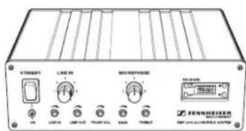
EMP 2015 receiver/amplifier combination
5 Components of the Soundfield System
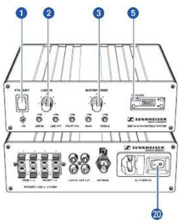
EMP 2015 receiver/amplifier combination
The heart of the Soundfield System is the EMP 2015 receiver with an integrated power amplifier to which you can connect additional audio and sound recording devices as well as FM systems for persons with impaired hearing.
The rear cover contains the enlarged overview drawings as fold-out.
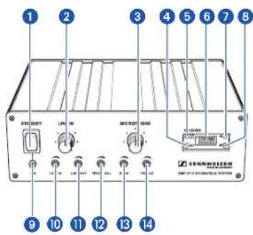
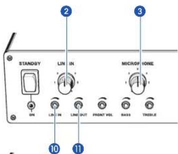
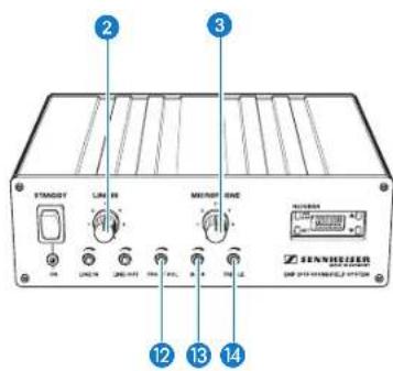
1 ON / STAND BY operating switch
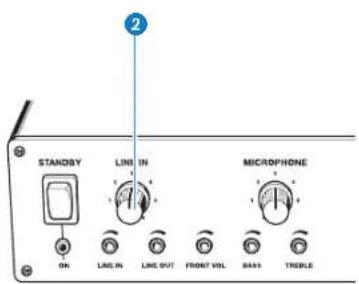
2 Volume control for external audio devices (LINE IN)
3 Volume control for wireless microphone (MICROPHONE)
4 SET button
5 ON/OFF button (receiver section)
6 LC display
7 ▲ button (UP)
8 ▼ button (DOWN)
9 POWER indicator
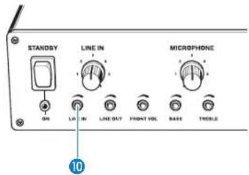
10 Line input sensitivity control (LINE IN)
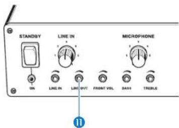
11 Line output level control (LINE OUT)
12 Level control for loudspeaker outputs FRONT-L and FRONT-R (FRONT VOL)
13 Bass control (BASS) (< 200 Hz)
14 Treble control (TREBLE) (> 4.5 kHz)
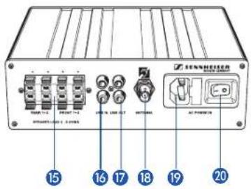
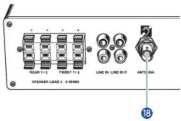
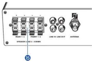
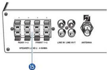
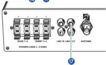
15 Loudspeaker outputs (REAR 1, REAR 2, FRONT 1, FRONT 2)
16 RCA sockets, inputs for external audio devices (LINE IN)
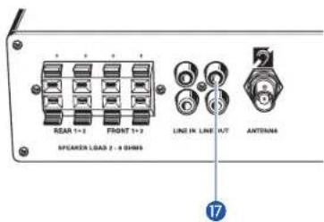
17 RCA sockets, outputs for external sound recording devices or FM systems for persons with impaired hearing (LINE OUT)
18 Antenna socket
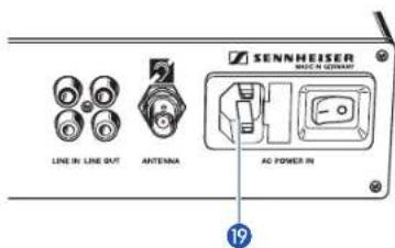
19 2-pin AC socket for connection of power cord (AC POWER IN)
20 Mains switch
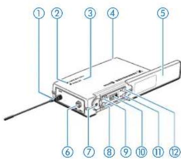
The rear cover contains the enlarged overview drawings as fold-out.
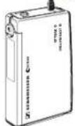
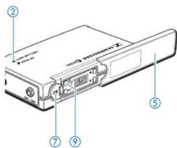
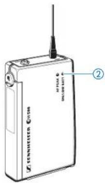
SK 500 bodypack transmitter
The bodypack transmitter transmits the signals of the connected microphone to the receiver section of the EMP 2015.
①⑫Antenna
②⑫Red LED for operation and battery status indication (ON/LOW BAT)
③⑫Yellow LED for audio peak (AF PEAK)
④⑫Cover plate for battery compartment
⑤⑫Cover plate for display and operating controls
⑥⑫Microphone and line input (MIC/LINE), 3.5 mm jack socket
⑦⑫MUTE switch (mutes the transmitter's audio signal)
⑧⑫SET button
⑨⑫ON / OFF button
⑩⑫LC display
⑪⑫▼ button (DOWN)
⑫⑫▲ button (UP)
6 Getting ready
EMP 2015 receiver/amplifier combination
Setting up the EMP 2015
The EMP 2015 is equipped with a temperature-controlled ventilation system. To ensure sufficient ventilation, please make sure that the ventilation apertures at the side panels are not covered. An integrated temperature monitoring device protects the EMP 2015 against overheating by turning it off if the temperature rises above a certain value. After sufficient cooling, the EMP 2015 is automatically turned on again.
Connecting the antenna and preparing the mains connection
Antenna
Connect the supplied telescopic antenna to the BNC socket 15 at the rear of the EMP 2015 and lock the bayonet catch.
▶ Pull out the antenna and align it.
Note:
For optimum reception, align the transmitting and receiving antenna vertically.
Mains connection
Plug the power cord into socket 19 at the rear of the EMP 2015.
SK 500 bodypack transmitter
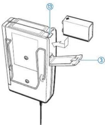
Inserting and replacing the battery
▶ Slide the cover of the battery compartment ③ in the direction of the embossed arrow until it clicks audibly.
▶ Open the cover.
▶ Insert the 9 V PP3 battery (IEC 6 LR 61). Please observe correct polarity when inserting the battery.
▶ Close the battery compartment.
To remove the battery, push the red lever ⑬ in the battery compartment towards the bottom side of the transmitter.
Note:
If powered by a standard PP3 battery, the operating time of the transmitter is approx. 6 hours. If powered by a rechargeable battery, the operating time is approx. 4 hours. Special note on rechargeable battery operation: For optimum operation, only use 9.6 V / 160 mAh NiMH batteries.
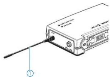
Connecting the antenna
▶ Screw the antenna ① onto the antenna socket (M3 connection).
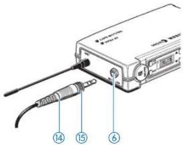
Connecting the microphone
Connect the 3.5 mm jack plug ⑭ from the microphone cable to the jack socket (MIC/LINE) ⑥.
- Lock the jack plug by screwing down the locking ring ⑮.
natural_image
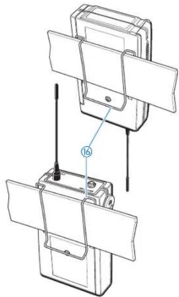
Technical line drawing of a mechanical assembly with two views and a numbered component (no text or symbols)Attaching the transmitter to clothing
The SK 500 transmitter is best attached to e.g. the belt with clip ⑯.
The clip is detachable so that you can also attach the transmitter with the antenna pointing downwards. To do so, withdraw the clip from its fixing points and attach it the other way round.
natural_image
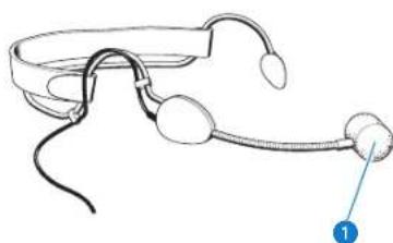
Line drawing of a pair of earpieces with clips and a label pointing to the pair (no text or symbols present)ME 3 headmic
The ME 3 headmic is adjustable to comfortably and securely fit your head.
Positioning the microphone
The ME 3 is a directional microphone, i.e. the sound inlet ① should always be directed towards the sound source (e.g. mouth). The sound inlet is marked with a little dot.
Installing the basic system
The basic system consists of the EMP 2015 receiver/amplifier combination, the SK 500 bodypack transmitter, a microphone and loudspeakers:
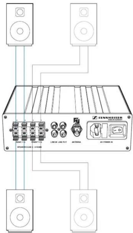
Installing the loudspeakers
The Soundfield System should generate a uniform sound field in the entire room. The speaker's voice should not be reproduced louder than normal but should be heard at the same level everywhere in the room.
To generate a uniform sound field, you require at least several loudspeakers for wall or ceiling mounting.
Install the loudspeakers so that two loudspeakers are not exactly facing each other. This can lead to cancellations, resulting in a non-uniform sound field.
Connecting the loudspeakers
The EMP 2015 has four independent power amplifiers. Therefore, you can connect up to eight loudspeakers to the EMP 2015 Soundfield System.

When installing a system with up to eight loudspeakers, make sure that the individual loudspeakers have an impedance from 4 to 8 ohms. The peak pulse power must be 30 W minimum.
When using more than one loudspeaker, make sure that the individual loudspeakers have the same polarity (+/-).

Danger of short circuit!
Never connect the loudspeaker cables to the ground and never allow the cables to come into contact with another cable or metal casing parts. During operation, the ends of the loudspeaker cables must never come into contact. This can cause a short circuit and may damage your speaker.
▶Connect a loudspeaker cable to each loudspeaker.
Connect each loudspeaker separately to the amplifier. Do not connect in "daisy-chain" configuration.
Connect one loudspeaker to each loudspeaker output 15.
Turning the system components on and off
Turning the amplifier on/off
The amplifier is fitted with both a mains switch 20 and an operating switch 1. Via the mains switch, the amplifier can be disconnected from the mains (position "0"). The mains switch can always remain set to "I".
When putting the system into operation, turn the amplifier on by setting the mains switch 20 to "I". The mains switch can then remain set to "I".
▶ During normal operation, turn the amplifier on or off by using the operating switch ①.
To disconnect the amplifier from the mains, set the mains switch to "0".
Turning the receiver section on/off
The receiver section is fitted with a separate ON / OFF switch ⑤ which can always remain set to "ON".
Adjusting the volume of the microphone
Set the MICROPHONE volume control ③ to "0" before you turn the amplifier on. Adjust the volume of the microphone after turn-on.
Adjusting the volume of connected audio devices
Set the LINE IN volume control ② to "0" before you turn the amplifier on. Adjust the volume of the connected audio devices after turn-on.
Note:
With the two volume controls ② and ③, the microphone and LINE IN signals can be mixed for reproduction at the loudspeaker output.
Turning the transmitter on/off
▶ Slide back the cover plate ⑤.
▶ Press the ON/OFF button ⑨ to turn the transmitter on. The red LED ② lights up.
To turn the transmitter off, press and hold the ON / OFF button until "OFF" appears on the display. You can then release the button. The red LED ② goes off.
Muting the transmitter
Use the MUTE switch ⑦ to noiselessly mute the transmitter's audio signal (this switch does not turn off the transmitter).
Operation
Transmitter and receiver section of the Soundfield System have been factory-preset to allow immediate use after system installation and turn-on. For excellent speech intelligibility, however, make sure that the transmitter sensitivity is adjusted correctly ( “Adjusting the sensitivity”).
Buttons
SET Press the SET button
- to select a menu,
- to change to the next menu,
- to return to the top menu level.
▲ Press the UP button
- to adjust the setting of a menu.
▼ Press the DOWN button
- to adjust the setting of a menu.
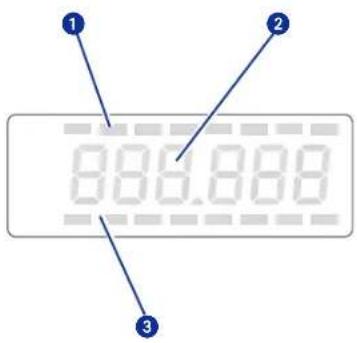
LC display panels
Receiver
1 8-step level display for received audio signal (AF level)
2 6-segment alphanumeric main display
3 8-step level display for received RF signal (RF field strength)
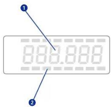
Transmitter
1 6-segment alphanumeric main display
2 3-step display for battery status
Battery status indication
The red LED ② and the 8-segment bargraph on the display provide information on the battery status.
Bargraph:
The bargraph indicates the (remaining) battery capacity in 3 steps:
8 segments: the full battery capacity is available,
4 segments: the battery capacity is sufficient,
1 segment: the battery is going flat, immediately replace the battery.
Note:
When turning on the transmitter with a partially used battery, it is possible that all eight segments may show for a short period of time – if this happens, re-check battery status after a few moments.
Red LED:
Red LED lit up: The transmitter is turned on and the
battery capacity is sufficient.
Red LED starts flashing: The battery is going flat! You should immediately replace the battery.
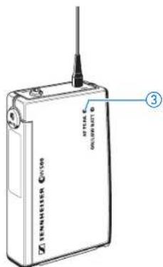
Peak indication
The yellow LED ③ at the top of the SK 500 transmitter lights up if the audio signal at the microphone/line input ⑥ is excessively high (AF PEAK).
Note:
The sensitivity of the microphone/line input ⑥ can be adjusted via the operating menu (“Adjusting the sensitivity”).
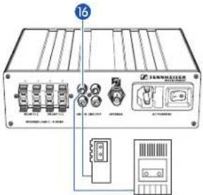
2 mono audio devices
Connecting external audio devices
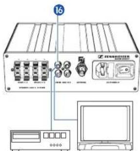
You can connect two mono or two stereo audio devices to the amplifier.
Connect the RCA plugs of the sound recording devices to the RCA sockets (LINE IN) 16 at the rear of the EMP 2015. For correct connection of the different audio devices, please refer to the diagrams at the left.
Note:
Stereo (left-right) signals are mixed in the amplifier and are then available as a mono signal.
▶ If possible, set stereo audio devices to “mono” operation. If sound problems occur, use the left channel of TVs and VCRs.
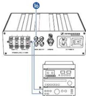
1 stereo audio device
2 stereo audio devices
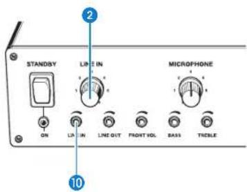
Adjusting the volume of an external audio device
You can adjust the volume of the connected audio device (e.g. VCR) separately from the volume of the speaker's microphone. If, however, you have connected two audio devices to the line input, the volume control adjusts the volume of both devices.
▶ Use the volume control (LINE IN) ② to adjust the volume of the connected device.
Note
If the audio signal sounds distorted, reduce the sensitivity of the system with control 10. If control 10 is turned counterclockwise as far as possible, the audio signal may not be audible.
EMP 2015 with two FM systems
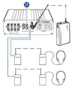
Connecting FM systems for persons with impaired hearing
You can connect an FM transmitter of an FM system of any manufacturer to each of the two line outputs (LINE OUT) 17.
The FM transmitter transmits the signals of one or several speakers and, if connected, an audio device to the FM receiver of the hearing impaired. As a result, the speaker doesn't have to wear several transmitters and microphones but only the transmitter and the microphone of the Soundfield System. In addition, the use of the Soundfield System ensures excellent sound quality.
For connecting an FM transmitter, you require a connecting cable fitted with an RCA plug and a 3.5 mm jack plug. (Some FM transmitters are fitted with a 2.5 mm jack socket.)
▶Connect the RCA plug of the connecting cable to one of the two RCA sockets (LINE OUT) ⑰ at the rear of the EMP 2015.
▶Connect the 3.5 mm jack plug of the connecting cable to the line input of the FM transmitter.
Adjusting the output level for FM transmitters
All standard FM transmitters are fitted with a line or audio input which should be used for connecting the transmitter. In general, the line output level control (LINE OUT) ⑪ on the EMP 2015 should be turned clockwise as far as possible.
Testing the FM system
Before you use an FM system for the first time, connect it to the Soundfield System as described above and test it via monitoring headphones to ensure problem-free operation.
If the speaker's voice sounds distorted, reduce the line output level by turning control ⑪ counterclockwise.


7 Special applications
Installing a system with up to eight loudspeakers
By connecting two loudspeakers to each loudspeaker output, you can connect up to eight loudspeakers to the Soundfield System:
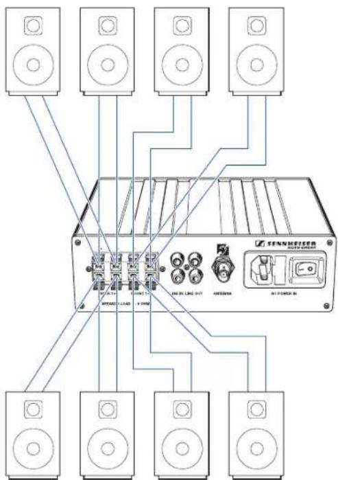
The Soundfield System should generate a uniform sound field in the entire room. Therefore, install the loudspeakers so that two loudspeakers are not exactly facing each other. This can lead to cancellations, resulting in a non-uniform sound field.

Connecting the loudspeakers
When installing a system with up to eight loudspeakers, make sure that the individual loudspeakers have an impedance from 4 to 8 ohms. The peak pulse power must be 30 W minimum.
When using more than one loudspeaker, make sure that the individual loudspeakers have the same polarity (+/-).

Danger of short circuit!
Never connect the loudspeaker cables to the ground and never allow the cables to come into contact with another cable or metal casing parts. During operation, the ends of the loudspeaker cables must never come into contact. This can cause a short circuit and may damage your speaker.
▶Connect a loudspeaker cable to each loudspeaker.
Connect each loudspeaker separately to the amplifier. Do not connect in "daisy-chain" configuration.
Connect two loudspeakers to each loudspeaker output 15.
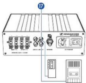
2 mono sound recording devices
Connecting sound recording devices
You can connect sound recording devices (e.g. tape recorder, dictating machine, etc.) to the RCA sockets (LINE OUT) 17 of the amplifier. The connected device records the same signal that can be heard in the room through the loudspeakers. If possible, connect the sound recording device via its line input (LINE IN, REC. IN, AUX IN, TB IN or similar).
Connect the RCA plugs of the sound recording devices to the RCA sockets (LINE OUT) 17 at the rear of the EMP 2015. For correct connection of the different audio devices, please refer to the diagrams at the left.
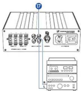
1 stereo sound recording device
Adjusting the recording level
The recording level is independent of the setting of the volume controls ② and ③. It is, however, dependent on the setting of the line input sensitivity control (LINE IN) ⑩. Control ⑪ adjusts the input level of the connected audio device.
The recording level of the line output 17 can be adjusted from 0 to 700 mVrms (corresponds to minus infinite to up to 0 dBU).
- The sound recording device is connected via its line input (LINE IN, REC. IN, AUX IN, TB IN or similar):
▶ Turn control ⑪ clockwise as far as possible and adjust the input level of the sound recording device.
- The sound recording device is connected via its microphone input:
▶ Set the input level of the sound recording device to maximum and use control ⑪ to adjust the recording level so that, during loud passages, distortion is avoided.
Note:
If control 11 is turned counterclockwise as far as possible, no audio signal will be available at the line output 17.
If you have connected two mono sound recording devices, the control adjusts the recording level of both devices.
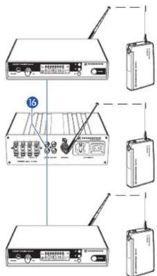
EMP 2015 with three transmitters and two additional receivers
Installing a system including several transmitters (team teaching)
With one Soundfield System, up to three speakers can speak simultaneously in the same room.
Transmitter 1 is directly received by the receiver section of the EMP 2015. Transmitters 2 and 3 require an additional receiver respectively. The receivers can be connected to the RCA sockets (LINE IN) ^16 of the EMP 2015. The signals of all transmitters are then reproduced by the loudspeakers.
For installing the system described above, you require additional SK 500 bodypack transmitters and EM 500 rack-mount receivers (“Recommended accessories”).
Connecting an EM 500 receiver
For connecting an EM 500 receiver, you require a connecting cable fitted with an 1/4" (6.3 mm) jack plug and an RCA plug (“Recommended accessories”).
▶Prepare the receiver for use as described in the receiver's instruction manual.
Connect the RCA plug of the connecting cable to one of the two RCA sockets (LINE IN) 16 of the EMP 2015.
Connect the 1/4" (6.3 mm) jack plug of the connecting cable to the 1/4" (6.3 mm) jack socket of the receiver.
▶ Set the transmitter and receiver of each transmission link to the same frequency.
Note:
Transmitter and receiver of each transmission link have to operate on the same frequency which must differ from the frequencies used by other transmission links in the room. With both the transmitter and receiver of the Soundfield System and the additional SK 500 transmitters and EM 500 receivers you can change the frequencies and store them in one of the 16 fixed frequency memories (“Operating steps for configuring a frequency memory”).
Adjusting the volume of the connected receivers
▶ Use the volume control (LINE IN) ② to adjust the volume of the connected receiver.
Note:
If you have connected two receivers to the line input, the volume control adjusts the volume of both receivers.
Adapting the system sensitivity to the connected receivers
▶ Turn the line input sensitivity control (LINE IN) ⑩ clockwise as far as possible.
Adjust the output level on the EM 500 receiver as described in the receiver's instruction manual.
Installing a system including two transmitters and an audio device
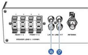
You can also connect an additional receiver and an external audio device (e.g. VCR) to the two line inputs (LINE IN) 16 of the EMP 2015. With such a system, the signals of two speakers speaking simultaneously and the signals of a VCR or similar are then reproduced by loudspeakers in the room. (In addition, you can connect sound recording devices to the two line outputs (LINE OUT) 17 of this system.)
To install this system, please proceed as described in the chapters "Installing a system with several transmitters (team teaching)" and "Connecting external audio devices".
Recommendations and tips
... for the ME 3 headmic
• Always use the microphone with a windscreen and position the microphone at the corner of the mouth.
- You can vary the bass reproduction by increasing/decreasing the talking distance.
• Make sure that the sound inlet is directed towards the mouth. The sound inlet is marked with a little dot.
... for the SK 500 bodypack transmitter
- For optimum transmission quality, make sure that the antenna and the microphone cable do not cross.
... for optimum reception
• Transmission range depends to a large extent on location and can vary from about 10 m to about 150 m.
- If reception conditions are unfavourable, you should use a remote receiving antenna (available as an accessory) which is connected via antenna cable.
- Observe a minimum distance of 50 cm between the receiving antenna and metal objects (such as cross members or reinforced-concrete walls).
8 Special adjustments
Basic functions of the Sennheiser operating menu
With the Soundfield System, all necessary adjustments to the transmitter and receiver section settings can be made by using the SET and ▲ and ▼ buttons. The settings are indicated on the respective displays.
Important:
After turn-on, press the ▲▼ buttons to switch between the factory-preset fixed frequency memories. The display starts flashing. Your selection becomes effective immediately. Press the SET button to acknowledge your selection. The flashing stops.
- Press the SET button to enter the top menu level:
By briefly pressing SET again, you can change to the next menu. After approx. one second, the selected menu appears on the display and then the current setting of the menu is indicated.
- Press the ▲/▼ buttons to adjust the settings of the selected menu:
The new setting starts flashing on the display. If you return to the previous setting, the flashing stops.
Important:
New settings become effective immediately and will be retained in memory on turn-off!
N.B.: When changing transmitter frequencies, care should be taken to avoid causing interference to other channels/users.
In the "tunE" and "Ch no" menu, the ▲/▼ buttons feature a "fast search" function. If you briefly press the ▲/▼ buttons, you can jump either forwards or backwards to the next setting. If you press and hold down a button, you can scroll through the settings.
- Press the SET button to return to the top menu level:
Have you finished your entries? Press the SET button to return to the top menu level. The display then switches back to the standard setting.
SenSit Adjusting the sensitivity (transmitter only)
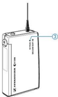
If the microphone sensitivity is not adjusted correctly, the speaker's voice can sound distorted or noisy. Distortion occurs if the microphone sensitivity is adjusted too high. In this case, the transmitter's yellow audio peak indication LED lights up ③. If, on the other hand, the sensitivity is adjusted too low, the teacher's voice will be overlaid with background noise.
Adjust the sensitivity so that the yellow audio peak indication LED ③ only lights up during the loudest passages.
The following figures are a guide to the best settings:
ME 3 headmic: -10 dB
ME 2 and ME 4 microphones (accessories): 0 dB
External sound sources (e.g. CD player): -30 / -20 dB


▶ Press the SET button to select the "SEnSit" menu. "SEnSit" appears on the display; after a short pause the current input sensitivity setting is indicated.
▶ With the ▲/▼ buttons you can now select a different setting. The sensitivity can be adjusted in 10-dB steps from 0 to -30 dB. The new setting starts flashing on the display and becomes effective immediately.
▶ Press the SET button to return to the top menu level. The display then switches back to the standard display.
SqELCH
Adjusting the squelch threshold (receiver section only)
The amplifier's receiver section is equipped with an adjustable squelch which eliminates annoying noise when the transmitter is turned off. It also suppresses sudden noise when the transmitter leaves the reception area.
598.008
Press the SET button to select the "SqELCH" menu. "SqELCH" appears on the display; after a short pause the current squelch setting is indicated.
With the ▲▼ buttons you can now select a different setting. The squelch can be turned off (0 dB) or adjusted in 5-dB steps from 5 dB to 40 dB. (Selecting a smaller value reduces the squelch threshold, selecting a higher value increases the squelch threshold.) The new setting starts flashing on the display. Set the squelch threshold – with the transmitter turned off – to the lowest possible value that suppresses hissing noise. With the squelch set to a high value, the receiver section will be less sensitive to interference but, on the other hand, the transmission range will be reduced.
Note:
If the receiver's squelch is set to "0 dB" and you turn the transmitter off, hissing noise with high dynamics will occur.
▶ Press the SET button to return to the top menu level. The display then switches back to the standard display.
DiSPL
Selecting the content of the standard display
With both transmitter and receiver section you can choose the content of the standard display i.e. whether the frequency (in MHz) or the channel number is displayed.
0.65.818
[Non-Text]
866.988
000 000 000 000 000 000 000 000
0.68.68
[Non-Text]
▶ Press the SET button twice to select the "DiSPL" menu. "DiSPL" appears on the display; after a short pause the current setting is indicated.
▶ With the ▲/▼ buttons you can now choose between:
Frequency: "FrEqu"
Channel number: "ChAnnL"
The new setting for the standard display starts flashing on the display.
▶ Press the SET button to return to the top menu level. The display then switches to the new standard display.
Configuring a frequency memory
Transmitter and receiver section of the Soundfield System have 16 switchable frequency memories respectively to store up to 16 transmission and receiving frequencies. The 16 factory-preset transmission/receiving frequencies are all intermodulation-free, i.e. you could operate up to 16 transmission links simultaneously in the same room.
If you use more than 16 Soundfield Systems in neighboring rooms, a minimum spacing of 400 kHz between two carrier frequencies must be maintained. Within the 32 MHz frequency window, you can therefore operate up to 80 systems without having to use a frequency twice.
Note:
In contrast to the Soundfield System, standard FM systems operate in the VHF band so that both systems cannot interfere with each other.
Operating steps for configuring a frequency memory

1. Select a frequency memory
▶ Press the ▲▼ buttons to select a factory-preset fixed frequency memory. The display starts flashing. Your selection becomes effective immediately.
▶ Press the SET button to acknowledge your selection. The display stops flashing. (If the SET button is not pressed, the device will store the new setting automatically on turn-off.)
Note:
You can choose the content of the standard display i.e. whether the frequency or the channel number is displayed ( “Selecting the content of the standard display”). The devices are factory-preset to show the frequency setting as standard.
tunE

2. Select a different frequency
▶ Press the SET button three times to select the "tunE" menu. "tunE" appears on the display; after a short pause the currently set frequency is indicated.
▶ With the ▲/▼ buttons you can now select a different frequency. The frequencies are tunable in 25-kHz steps. The new frequency starts flashing on the display and becomes effective immediately.
▶ Press the SET button to return to the top menu level. The display then switches back to the standard display.
Important note:
Set the transmitter AND the receiver to exactly the same frequency!
Ch no
3. Assign a channel number
You now have to assign the frequency memory a channel number (from 0 to 255). If you use several Soundfield Systems in neighboring rooms, you can assign channel numbers 1 - 16 to one group of transmitters and receivers and channel numbers 17 - 32 to the next group, etc. The 16 fixed frequency memories are factory-preset to channel numbers 01 - 16.


Press the SET button four times to select the "Ch no" menu. "Ch no" appears on the display; after a short pause the currently assigned channel number is indicated.
▶ With the ▲▼ buttons you can now select a different channel number. The new channel number starts flashing on the display and becomes effective immediately.
Note:
Channel numbers which have already been assigned to a fixed frequency memory are skipped!
▶ Press the SET button to return to the top menu level. The display then switches back to the standard display.
Note:
Use the same channel number for both transmission and receiving frequency!
Loc Activating/deactivating the lock mode
After you have finished your entries, you can lock the buttons on the transmitter and the receiver section to prevent accidental programming or turning off during operation.

Activating the lock mode
▶ Press the SET button five times to select the "Loc" menu. The current setting is indicated on the display.
▶ Press the ▲ button to activate the lock mode. "Loc on" starts flashing on the display.
▶ Press the SET button to return to the top menu level.
Note:
The ▲/▼ buttons or the ON/OFF button are now locked. To turn the transmitter off, first deactivate the lock mode.


Deactivating the lock mode
▶ Select the "Loc" menu by pressing the SET button. "Loc on" appears on the display.
▶ Press the ▼ button to deactivate the lock mode. "Loc OFF" begins to flash on the display.
▶ Press the SET button to return to the top menu level. The display switches back to the standard display and the buttons can now be operated as usual.
Acoustically adapting the Soundfield System to a room
Before you use the Soundfield System for the first time in a room, you should acoustically adapt it to the room.
▶Turn on both the bodypack transmitter and the microphone.
▶ Reset the two volume controls ② and ③ on the amplifier to "0".
▶Turn on the amplifier.
Adjust the volume of the microphone so that the speaker's voice can be clearly understood but doesn't sound unnaturally loud. In long, narrow rooms it might be advisable to reduce the level of the front loudspeakers compared to that of the rear loudspeakers by means of the loudspeaker output level control 12, since the speaker's voice additionally supports the front part. You can reduce the level of the front loudspeakers compared to that of the rear loudspeakers by up to 12 dB.
▶ Use the bass control 13 and the treble control 14 to adapt the sound of the voice to both the acoustic situation in the room and the characteristics of the connected loudspeakers.
Many of the sounds which are important for speech intelligibility are in the high frequency range above 4 kHz. Hissing noise and so-called plosives ([s], [t], [f], etc.) mainly consist of high frequencies. In order to ensure that the speaker can be clearly understood, use the treble control 14 to adjust the treble response to a sufficient value. If the high frequencies are enhanced too much, the voice sounds "sharp", which might be disturbing in the long run and increases the risk of feedback.
Use the bass control 13 to set the bass response so that the voice doesn't "hum". Since the low frequencies are not that important for speech intelligibility, it might be advisable to adjust the bass response to a comparatively low level during classes.


9 Care and maintenance
The components of the Soundfield System should be cleaned from time to time. Use a damp cloth for cleaning. Do not use solvents or solvent-containing cleansing agents as these could damage the surface of the components.
Replacing the windscreen
If the windscreen shows signs of wear such as tears or holes, replace the windscreen. To do so, pull the old windscreen from the microphone and gently slide on the new one.
10 Troubleshooting
Error checklist
Problem Possible cause What to do
You hear whistling noise
No operation indication
No RF signal and no audio signal are turned off
RF signal available but no audio signal
Speaker's voice too soft
Speaker's voice too loud
Speaker's voice distorted
Volume of sound reproducing device adjusted too high
- Microphone volume is adjusted too high microphone volume control
• Battery is flat (transmitter)
• No mains connection (EMP 2015)
• Transmitter and/or receiver section receiver section on
• Transmission frequency is not the same as the receiving frequency
• Transmitting antenna is not connected
• Transmitter is muted ("MUTE")
- Receiver section's squelch threshold is adjusted too high
- Microphone is not connected
- Microphone volume is adjusted too low
- Microphone is covered or - Position the microphone at positioned too far from the mouth the corner of the mouth
- Microphone volume is adjusted too high microphone volume control
- Transmitter sensitivity is adjusted too high value (→ “Adjusting the
- Receiver section's AF output level is adjusted too high
• Volume at the line input is adjusted too high audio device with the
- Reduce the volume with the
- Replace the battery
- Check to see if the mains plug is connected and if the amplifier is turned on
• Turn the transmitter and/or
- Set the transmitter and the receiver section to the same frequency (→ “Special adjustments”)
- Connect the antenna
- Deactivate the muting function
- Adjust the squelch threshold to a lower value (“Adjusting the squelch threshold”)
- Connect the microphone
- Increase the microphone sensitivity on the transmitter or the microphone volume on the EMP 2015
- Position the microphone at rner of the mouth
- Reduce the volume with the
- Adjust the sensitivity to a lower sensitivity")
- Reduce the volume with the microphone volume control
- Reduce the volume of the corresponding volume control
Problem Possible cause What to do
Dropouts
Speaker's voice overlaid antenna with background noise
• Antenna sensitivity is not sufficient
• Use a remote or telescopic
• Transmitting antenna is not connected
- Connect the antenna
- Connection of transmitting antenna has worked loose
- Screw the antenna tight
• Transmission frequency is not the
- Set the transmitter and the
same as the receiving frequency receiver section to the same frequency
(“Special adjustments”)
Sound is not clear / rough
• Several transmitters in the same room or in neighboring rooms
• Check the frequency settings
- Microphone is covered or positioned too far from the mouth
(“Special adjustments”)
• Transmission frequency is not the same as the receiving frequency re
• Position the microphone at the corner of the mouth
- Set the transmitter and the section to the same
frequency
(“Special adjustments”)
If problems occur that are not listed in the above table, please contact your local Sennheiser agent for assistance.
11 Recommended accessories
ME 2 Clip-on microphone for SK 500, condenser, omni-directional
ME 4 Clip-on microphone for SK 500, condenser, cardioid
EM 500 Rack-mount receiver for operating an additional transmission link
SK 500 Bodypack transmitter for "team teaching"
Connecting cable for connecting an EM 500, 1/4" (6.3 mm) jack plug and RCA plug
GA 1 Rack adapter for EM 500, for mounting two EM 500 into a 19" rack
DC 1 DC power adapter, for external 12 V DC powering of SK/EK 500 (instead of 9 V PP3 battery)
12 Specifications
EMP 2015 receiver/amplifier combination
Amplifier section
Operating voltage 230 V (EU and UK version)
115 V (US version)
Power consumption < 3 W (stand by)
<20 W (position "ON")
< 200 W (max. rms level)
Fuse 2 AT
AF output power 4 x 10 W at 4 (rms)
4 x 20 W at 4 (peak)
Harmonic distortion (at nom. dev., 1 kHz)
Line input 0.5 %
Receiver 1 %
Output impedance 4 x 2...8 Ω
Frequency response Line input 20 - 18,000 Hz
Receiver 70 - 18,000 Hz
Signal-to-noise ratio
(LINE OUT) >90 dBA rms
(SPEAKER OUT) >80 dBArms
Temperature range
0^ - 40^
Protection class
2
Dimensions
210 x 70 x 205 mm
Weight
2,600 g
Receiver section
Modulation
FM mono
Frequency ranges
518 - 550, 630 - 662, 740 - 772, 790 - 822, 838 - 870 MHz
Transmission/receiving frequencies
1280, tunable in steps of 25 kHz,
Switching bandwidth
16 switchable fixed frequency memories
Noise reduction system
32 MHz
Nominal deviation / peak deviation
Sennheiser HDX
Sensitivity (with HDX, peak dev.)
±24 kHz / ±48 kHz
Antenna input
< 2.5 μV
Antenna input impedance
BNC
50 Ω
SK 500 bodypack transmitter
Modulation
FM mono
Frequency ranges
518 - 550, 630 - 662, 740 - 772, 790 - 822, 838 - 870 MHz
Transmission/receiving frequencies
1280, tunable in steps of 25 kHz,
Switching bandwidth
16 switchable fixed frequency memories
RF output power at 50 Ω
32 MHz
Power supply
typ. 10 mW
Max. current consumption at nom. voltage
9 V PP3 alkaline manganese battery (IEC 6 LR 61) or
Dimensions
9.6 V/160 mA rechargeable battery
Weight
approx. 40 mA
110 x 65 x 22 mm
approx. 255 g