JK-06 - Security Camera Joblotron - Free user manual and instructions
Find the device manual for free JK-06 Joblotron in PDF.


User questions about JK-06 Joblotron
0 question about this device. Answer the ones you know or ask your own.
Ask a new question about this device
Download the instructions for your Security Camera in PDF format for free! Find your manual JK-06 - Joblotron and take your electronic device back in hand. On this page are published all the documents necessary for the use of your device. JK-06 by Joblotron.
USER MANUAL JK-06 Joblotron
• Detailed manuals for all included components can be found on the enclosed CD or on the Jablotron website www.jablotron.com
1. Kit contents
All items in the kit are enrolled and preprogrammed. The detectors and remote controls have batteries pre-installed.
| Item description address | |
| JA-60N wireless door sensor 1 | |
| JA-60P wireless motion detector 2 | |
| JA-60F wireless keypad c1 | |
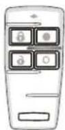
| RC-44 remote control c2 | |
| UC-260 wireless indoor siren panel is enrolled | |
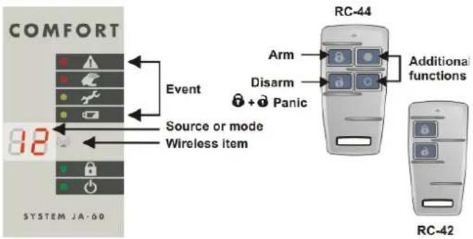
The RC-42 is the same remote control as the RC-44 except that it is built into the housing witch only two buttons ( 🔊 & 🔒 which have identical functions to the left pair of RC-44 buttons.
2. Before installation
Decide upon suitable locations for all of the items. The wireless keypad should be within 20m of the control panel.
There should be power and a telephone line available for the control panel.
3. Control panel installation
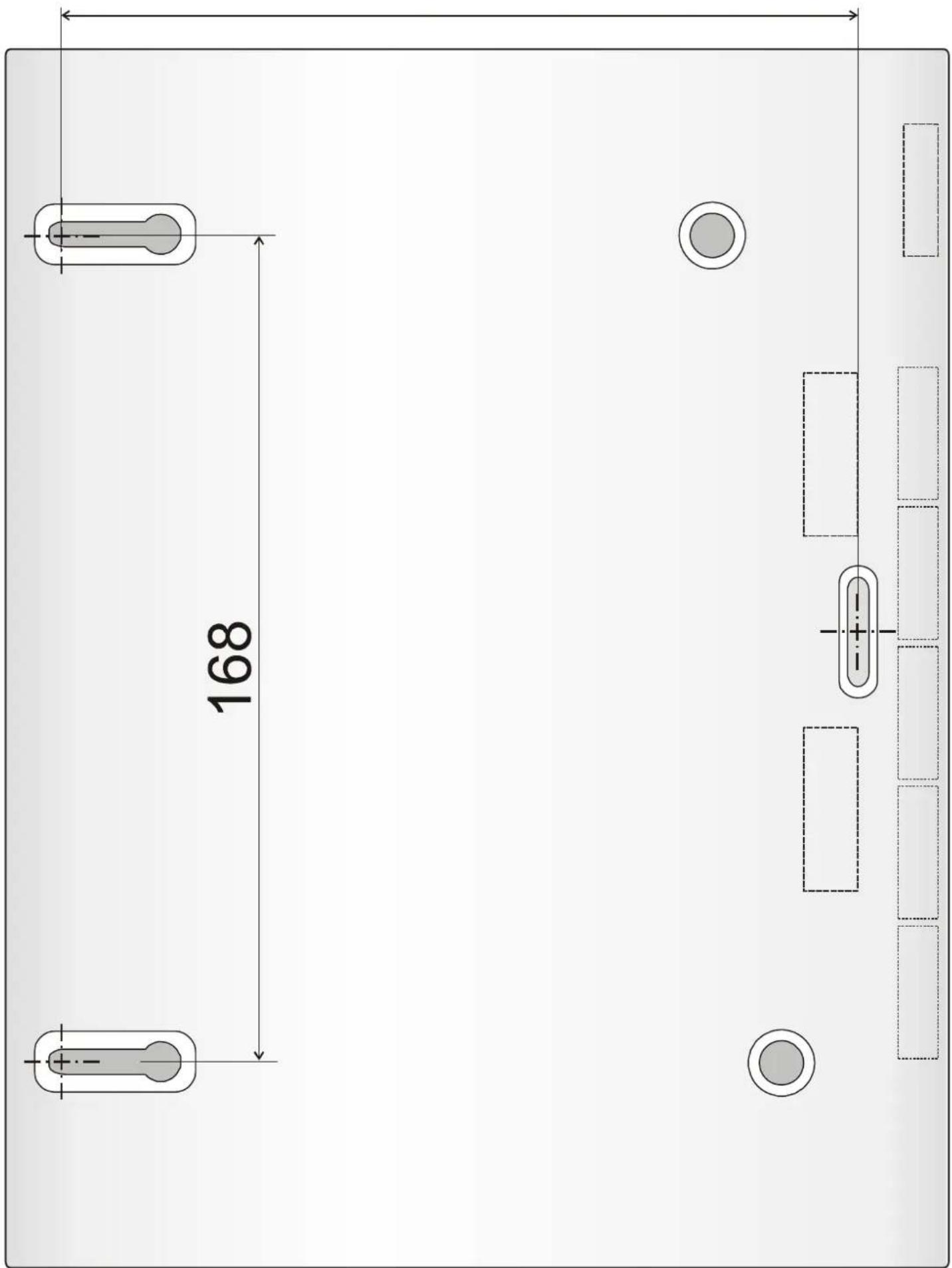
a) Install the control panel - see drilling plan on the last page of this manual.
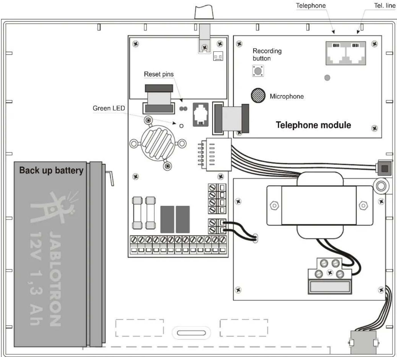
b) Connect the telephone line and telephone cable to the connectors on the telephone module inside the control panel
c) Check that the telephone works normally as before
d) Install and connect the backup battery to the control panel
e) Connect the AC power to the control panel
f) The Green LED should flash in the control panel
g) Connect the keypad's batteries (pull out the red tape to activate batteries). P will be indicated on the keypad (programming mode).
- If F is indicated, there is no communication with the control panel.
- Enter F0 6060 to reopen the P mode in case you accidentally close it by pushing the N key
- To save the keypad batteries, close its cover while it is in the P mode
text_image
Telephone Tel. line Green LED Reset pins Recording button Microphone Telephone module Back up battery JABLOTRON 12V 1,3 Ah4. Detectors and accessories installation
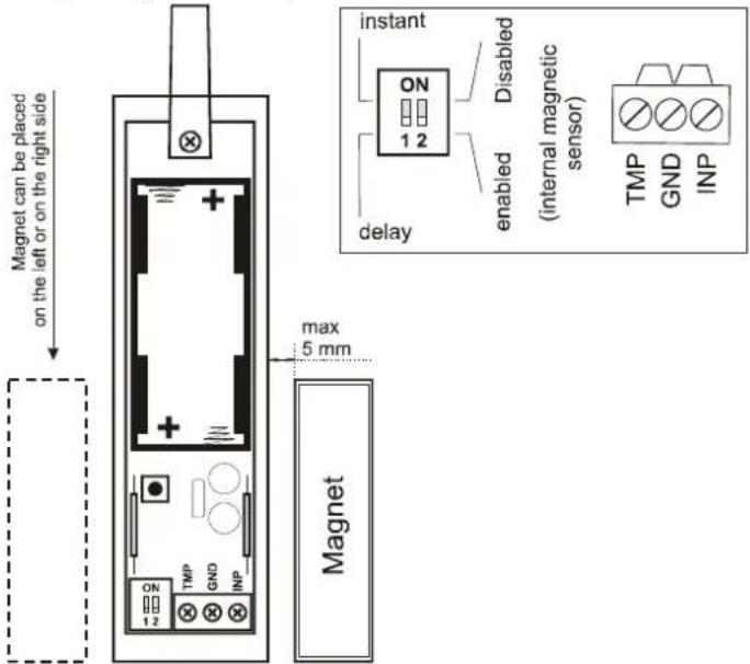
a) Install the JA-60N magnetic detector to the door (antenna pointing up or down)
text_image
Magnet can be placed on the left or on the right side instant ON 1 2 Disabled enabled (initial magnetic sensor) delay TMP GND INP max 5 mm Magnetb) Install the JA-60P motion PIR detector
text_image
A Don't tight this screw TOP new temperature laser attach B click C open
text_image
JA-60P coverage 120 zone C zone B zone A 120 height 1.5 2.5 avoid location against windows or close to a heater zone C zone B zone A 1.8 3.7 range [m]c) Select Instant or Delay reactions via DIP switches inside the detectors.
d) Connect detector's batteries (pull out the red tape to activate the batteries)
e) Attach the keypad to the desired location
f) Plug in the UC-260 wireless siren into a power socket
5. Enrollment of additional accessories
If you install additional detectors (max. 32), you have to enroll them. The system should be in the P mode (if not enter F0 6060):
a) Press 1 to open the learning mode*
b) The next free detector position will be displayed on the keypad.
c) Install batteries into all new detectors step by step to enroll them (system will automatically offer the next free position)
d) To scroll through sensor positions, press 1 (up) or 7 (down)
e) To enroll a second detector to an occupied position press 5 before you install the detector's batteries
f) To exit the learning mode press the N key
Wireless keypad (JA-60F) enrolls after you install its battery while in the learning mode.
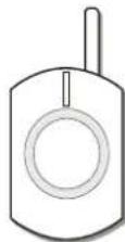
Remote control (RC-4x) enrolls after you press and hold both and buttons while in the learning mode.
Wireless outdoor siren (JA-60A) enrolls after it is powered while in the learning mode
To enroll the control panel to UC receivers enter 299 on the keypad while in the P mode
Check individual item manuals for more details
*Learning mode will also open after shortening of the Reset pins in the control panel.
6. Detectors and controllers testing
a) The system should be in the P mode (if not enter F0 6060)
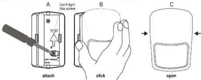
b) Trigger detectors – their addresses (1=door and 2=PIR) should be indicated (if the PIR detector does not react, reenter its testing mode by opening and closing its cover)
c) Press button 🔒 on the RC-4x remote control - c2 will be indicated
7. To measure strength of the radio signal
a) While in P mode, press 1 and then using 7 scroll to position 1
b) Press 8 to start measuring
c) Activate the door detector to view its signal strength
d) Using the 1 key, scroll to the next position (2 PIR) and check its signal strength (if the PIR detector does not react, reenter its testing mode by opening and closing its cover)
e) Repeat step d) to check all enrolled items. The wireless keypad (c1) signal is indicated after you trigger its tamper. Remote control (c2) is indicated after you press it's button 🔒.
f) Change the location of an item if its signal is lower than 2
g) Return to P mode by pressing the N key
8. Programming of the system
a) System should be in the P mode (if not enter F0 6060)
b) Using the following sequences you can program:
| Function | Sequence | comments |
| Your installer code* | 5 xxxx xxxx | 6060 factory default xxxx new code |
| Exit delay | 20x | 3=30sec factory def. |
| Entrance delay | 21x | 3=30 sec factory def. |
| Alarm duration | 22x | 4=4min factory def. |
| Telephone numbers entering | 7 yy...y F n | yy...y=tel. number n=memory 1 to 4 7F0Fn will erase memory n |
| Alarm voice message recording | 85 then push and hold REC button on the telephone module and talk to the microphone – max. 10sec. | |
| Time & date | 4 hh mm DD MM YY | |
| Remote Comlink access code* | 07xxxxxxxxx | 00000000 factory def.xx..x=new code,8digits |
| Remote Comlink access enabling | 05x | x=0 disabled x=6 enabled after 6 rings |
See control panel installation manual for more details.
* Must be changed
9. Finishing installation
a) Fill in information on the sticker label and attach it inside the keypad cover.
b) Switch the system to standby (by pressing the N key)
c) Instruct the user how to operate the system
text_image
COMFORT Event Source or mode Wireless item 38 SYSTEM JA:00 Arm Disarm + Panic Additional functions RC-44 RC-42- Keypad operation
| Entry | Function |
| user code | Arming / Disarming |
| F1 / [IMAGE] | Arming without code |
| F2 / [IMAGE] | Partial arming |
| F3 / [IMAGE] | Door lock opening |
| F4 | Memory reading |
| F5 | New master code (example: F5 1234 2789 2789) |
| F6 | User codes setting (example: F6 1234 03 3344) |
| F7 / [IMAGE] | Under duress disarming |
| F8 | Appliance control (F81 = ON, F80 = OFF) |
| F0 M.code | User testing mode (example F0 1234) |
| N | Escape & fault details reading |
11. Specifications
Power 230 VAC, max 0.1 A, supervised, class II
Backup battery 12 V, 2.26 Ah, normal life time 5 years
Backup power output 13VDC, the max. permanent current is 0.4
or 1A for max. 15 min (1 cycle per hour),
Self consumption of the control panel is 30 mA; JA-60E 25 mA
Hard-wired inputs 4 input zones, selectable triggering:
Wireless zones 16 zones (2 detectors can be enrolled to each
Wireless controllers max. 8 (JA-60F, RC-22, RC-44)
Access codes master code and 14 user codes.
Wired outputs Alarm relay dry contacts 1A/60V;
Programmable outputs PgX, PgY connect to the GND max. 0,1 A
Siren output 12 V, 0.7 A
Events memory 127 most recent events
Working frequency* 433.92 MHz; digital hopping code; supervised
communication
Comply with EN 50131-1, EN 50131-6
Security grade 2 (low to medium risk)
Environmental class II indoor – general (-10 to 40oC)
Safety EN 60950, class II
EMC ETS 300683
Radio characteristics ETSI EN 300220
Can be operated according to ERC REC 70-03

Jablotron Alarms a.s. hereby declares that the JA-63 Profi control panel is in compliance with the essential requirements and other relevant provisions of Directive 1999/5/EC. The original of the conformity assessment can be found on the web site www.jablotron.com, Technical Support section.
Note: Dispose of batteries safely depending on the type of the batteries and local regulation. Although this product does not contain any harmful materials we suggest you to return the product to the dealer or directly to the producer after usage.
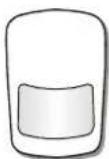
Motion detector
JA-60P
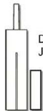
Doors, Windows
JA-60N
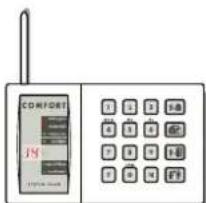
text_image
COMFORT 19 19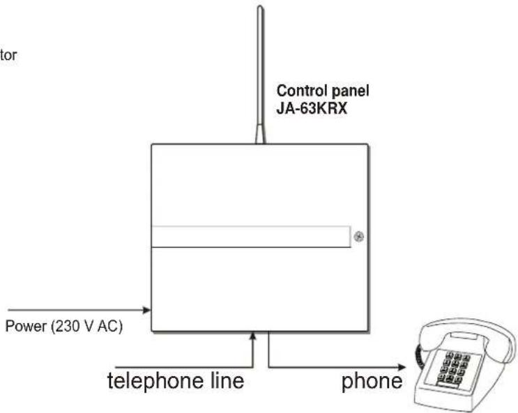
text_image
Control panel JA-63KRX Power (230 V AC) telephone line phoneWireless keyboard JA-60F
Indoor siren
UC-260
(230 V AC)
Remote control
RC-4x

JABLOTRON ALARMS a.s., Pod Skalkou 33
466 01 Jablonec nad Nisou
Czech Republic
Tel.: +420 483 559 911
fax: +420 483 559 993
Internet: www.jablotron.com
162
text_image
168Control panel drill plan