JA-80V - Security Camera Joblotron - Free user manual and instructions
Find the device manual for free JA-80V Joblotron in PDF.


| Product Type | LAN/PSTN Communicator Module for Oasis 80 Security System |
| Brand | Joblotron |
| Model | JA-80V |
| Power Supply | 12 V DC (from control panel) |
| Standby Consumption | ~35 mA |
| Maximum Consumption | 1 A (during communication) |
| Operating Temperature | -10 °C to 40 °C |
| Compliance | EN 50131-1, EN 50136-1-1, EN 60950, FCC Part 15 |
| Main Functions | Event reporting via SMS/phone call to 8 numbers; remote control by phone keypad or SMS; remote programming via Internet (GSMLink); ARC reporting (IP CID and CID protocols); toll-free control by unanswered calls |
| Communication Interfaces | PSTN telephone line (CLIP) and Ethernet LAN (10/100 Mbit) |
| Installation | Inside Oasis 80 control panel housing; requires screw mounting and bus connection |
| Configuration Methods | System keypad (service mode), SMS instructions, Comlink software, GSMLink web interface |
| Indicators | Green (communication status), Red (ARC fault), Yellow (Ethernet status) |
| Supported Languages | 17 languages including English, French, German, Spanish, etc. |
| Safety Precautions | Disconnect power before installation; use only with approved control panels; avoid exposure to moisture |
| Maintenance | No user-serviceable parts; cleaning with dry cloth; periodic communication tests recommended |
| Spare Parts | Not listed; contact manufacturer for replacements |
| Environmental Class | II (indoor use) |
Frequently Asked Questions - JA-80V Joblotron
User questions about JA-80V Joblotron
0 question about this device. Answer the ones you know or ask your own.
Ask a new question about this device
Download the instructions for your Security Camera in PDF format for free! Find your manual JA-80V - Joblotron and take your electronic device back in hand. On this page are published all the documents necessary for the use of your device. JA-80V by Joblotron.
USER MANUAL JA-80V Joblotron
The JA-80V LAN / PSTN line communicator
The communicator is a component of the Jablotron Oasis 80 system. It is designed to be installed within the control panel housing. This manual is valid for firmware version XA64005.
When connected to a PSTN telephone line and LAN (Ethernet) data network it allows the following:
• event reporting by SMS (to up to 8 telephone numbers)
• event reporting by phone call with an acoustic warning
- event reporting to an ARC (Automatic Receiving Centre – also known as a Central Monitoring Station) - up to 2 ARCs
- remote control and programming by phone (remotely authorizing a phone keypad or by SMS instructions)
- the remote control of appliances in a house by dialling in from an authorized number (free of charge with unanswered calls)
- remote control and programming via the Internet (www.GSMlink.cz)
The communicator can also be connected only to a telephone line or only to a LAN network. In these cases it will provide the following functions:
tel. line only: remote control by phone, event reporting by SMS and by phone calls and event reporting to ARC2 (CID protocol)
➢ LAN only: remote access via the Internet, event reporting to ARC1 (IP CID protocol)
1. Installation in the control panel
If you purchased the communicator module separately, it should first be installed in the Oasis control panel as follows:
a) The control panel power must be switched off (both mains and battery)
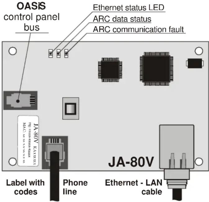
b) Fit the communicator inside the control panel housing using screws and connect its digital bus RJ cable to the main board
c) Connect the PSTN telephone line cable – the telephone line should support CLIP protocol (EN 300 089 V3.1.1) with Caller ID recognition and SMS transfer in text format activated (contact your phone line provider for more details).
text_image
OASIS control panel bus Ethernet status LED ARC data status ARC communication fault JA-80V JA-80V Label with codes Phone line Ethernet - LAN cableFig. 1 Communicator wiring
2. Powering up the communicator for the first time
If the communicator is installed in the control panel then:
a) Have the LAN (Ethernet) cable ready
b) Switch on the control panel power (mains and battery). The communicator's green LED should turn on = no events to send to the ARC.
c) If your LAN network does not provide an automatic DHCP, program the Ethernet network parameters manually (see 5.18).
d) connect the LAN cable (10/100 Mbit). If communication with the network is correct the yellow LED will be constantly lit.
If it starts flashing, check the DHCP parameters, if it turns off (after 3 sec. of flashing) then the communicator is not connected to the Ethernet at all.
e) If communication to an ARC is desired, then all ARC parameters have to be programmed according to the ARC provider's specifications.
f) Key in 98101 - to set texts of the communicator to English language.
g) Close the control panel cover
3. User functions of the communicator
The following text describes all communicator features. The installer should show the end user how to operate the functions used in a particular installation.
3.1. Temporarily authorizing a phone keypad to be a system keypad
It is possible to operate the system remotely by temporarily authorizing a phone keypad as follows:
a) dial the system's phone number
b) after 25 seconds of ringing (programmable) the system will answer with a short beep
c) key in a valid access code on the telephone keypad (e.g. 8080 or 1234 if factory default settings are still valid)
d) the phone keypad will behave as a system keypad and an acoustic signal in the receiver will indicate the control panel status: 1 beep = SET, 2 beeps = UNSET, 3 beeps = Service mode, 4 beeps = incorrect code entry, siren sound = alarm
e) now the system can be operated from the phone keypad the same way as from the system keypad – including the commands starting with * (for example *81 to turn the PGX output on)
f) to exit this mode simply end the phone call (if nothing is entered within a minute, the phone call will end automatically anyway)
Notes:
- do not enter sequences on the phone too fast, each key signal needs a certain time to be sent
- a fixed-line phone can also be used to operate the system remotely the same way (the phone must use tone dialling)
- Phone keypads have to be re-authorized each time the system is called by entering the codes specified earlier, as phone keypads are only authorized as system keypads for the duration of a call to the system.
3.2. SMS instructions to control the system remotely
The telephone line connected to the communicator is used to receive SMSes but has to support CLIP protocol for SMS transfer in text form for this feature to work. The SMS transfer parameters should also be programmed – see 5.11 and 5.12.
All incoming SMSes are checked by the communicator and if there are any instructions to the system, they will be performed. Each instruction message must have the following format:
code instruction
(valid code space instruction)
Valid code = any valid code in the system (e.g. 8080, 1234 etc.)
The factory-default instruction texts (editable - see 5.4)
| Instruction | Function | Notes |
| SET | setting (arming) | setting or unsetting (the same way as if the code used is entered on the system keypad), If the system is already in the desired mode, it will not change |
| UNSET | unsetting (disarming) | |
| STATUS | status interrogation | including ARC communication (shown as MS1 and MS2) |
| MEMORY | last event interrogation | The last event recorded in the control panel memory |
| PGX ON | turns on PGX | the PG output has to be programmed for the function: on/off (by 237/247) or 2 second switching (by 238/248) |
| PGX OFF | turns off PGX | |
| PGY ON | turns on PGY | |
| PGY OFF | turns off PGY |
Example: by sending: "code SET" (valid code space SET) the system will set (if it is already set it will not change its status)
Notes:
- performance of the instruction is confirmed by an SMS reply
- the instruction texts are not case-sensitive and only ASCII characters are allowed
- only one instruction can be in an instruction SMS
- a setting/unsetting instruction starting with the service code will only be performed if setting/unsetting with the service code is enabled in the control panel (to protect against unauthorized setting/unsetting by installers)
- if there is any other text in the instruction not separated by “%”, the instruction will not be performed
- if you are sending an instruction and you are not sure whether any other text will be automatically added to the SMS (for example, when using an SMS internet gate) type the instruction as: %code instruction%%
- no other device receiving SMSes can be connected to the same telephone line as the communicator.
3.3. Toll-free remote control by unanswered calls from pre-authorized phones
If the telephone line provides CLIP protocol caller ID, then a limited number of system functions can be activated remotely by calling the system from pre-authorized phones and terminating calls before the system answers. This way limited control of the system is free of call charges. It is possible to pre-authorize phone numbers stored in memories M1 to M8 (also used for event reporting – see 4).
To pre-authorize a telephone number store * at the end of the number and follow it by a single digit (1, 2, 3, 8 or 9) – see the notes in section 4.
If this number calls, the communicator generates “* digit” after the first ring (as if it had been entered manually on the system keypad). This toll-free remote control by unanswered calls enables the following functions according to the digit stored at the end (after the *) of the tel. number in memory:
*1 setting the complete system (= ABC keypad button)
*2 setting section A (= A button)*
*3 setting sections A & B or B (= B button)*
*8 PGX turns on for 2 sec. (if PGX is programmed for the pulse function)
*9 PGY turns on for 2 sec. (if PGY is programmed for the pulse function)
Notes:
- if a phone sends no caller identification data it cannot be used for this type of remote control by phone
- if phone calls end before the control panel answers, remote control is for free
- a phone which is pre-authorized for toll-free remote control can also temporarily authorize its keypad to fully operate the system (see 3.1) – just let it ring until the control panel answers the call
- if it is desired that the phone which is authorized for toll-free remote control should not receive event reports, then turn the reports off for that tel. number (see 5.3).
- setting (arming) with *1, *2 and *3 will work only if enabled in the control panel
4. Reporting to phones
The communicator can report events occurring in the Oasis system by sending SMS reports (if the telephone line supports CLIP protocol SMS transfer) and/or by calling phone numbers with an acoustic signal (mostly used as audible notification of an SMS to be read). Reporting can be programmed for up to 8 phone numbers.
The most frequently desired reports are already assigned to the telephone number memories by factory-default, so you only need to program tel. numbers to the particular memories which have the desired reports already assigned. If desired, other events can be reported to the number too, i.e. the list of event reports assigned to the number can be changed (see 5.3)
Factory-default reports assigned to the numbers M1 to M8
| M | Reports |
| 1 | Alarms and faults by SMS |
| 2 | |
| 3 | Alarms and faults by SMS + phone call (if you answer the |
| 4 | |
| 5 | Alarms by SMS + a phone call, with Settin g/Unsetting |
| 6 | |
| 7 | Alarms by phone call (if you answer the call you hear a siren sound) |
| 8 Technical fault by SMS (suitable for an installer) | |
To program phone numbers to the M memories, enter the following sequence while in Service mode:
81 M xxx...x *0
where:
M
is memory 1 to 8
xxx...x is a phone number (max. 20 digits)
Example: entering 81 5 777 777 777 *0 will store the number 777777777 in memory M5 (Alarms will be reported by SMSes + phone calls, Setting/Unsetting and faults only by SMS)
To erase a number from memory M enter: 81 M *0
Notes:
- international phone numbers have to start the same way as if you call them from the phone line which is connected to the communicator.
- SMS report text consists of: installation name, event name, number and name of the event source (device or code), date and time. Example: "Report from your alarm: setting 47: device Time 01.08. 11:27"
- if other events or texts should be reported to a particular number, change the communicator settings (see 5.3 and 5.4)
- when storing tel. numbers, if you key in *7 after the last digit of the phone number (the symbol * is also stored) and continue with one more digit (1, 2, 3, 8 or 9), then if this tel. number calls the system, the system will behave as if "* digit" had been keyed in just after the first ring, i.e. as if it had been entered manually on the system keypad – see section 3.3. Example: entering 81 5 777 777 777 *79 *0 authorizes calls from tel. number 777777777 to trigger output PGY for 2 seconds (after the first ringing signal from this number the *9 command will be executed. The PGY output should be programmed for a 2 sec. pulse function. This setting is suitable for opening an electric door lock, automatic gate etc.
4.1. Programming
The most convenient programming is best done by a PC running Comlink software or via the Internet and website: www.GSMLink.cz or by programming SMS – PRG sequence
Programming is also possible via the system keypad:
- The control panel must be in Service mode - if it is not, enter *0 Service code (factory default: 8080) while the system is unset.
- Enter the relevant programming sequences – see the following description
-
To exit service mode press the # key
-
Programming sequences
| Function | Sequence | Options | Factory default |
| Language setting | 981 xx | xx=01 to 17 where:01=EN,02=CZ,03=SK,04=NL,05=DE,06=PL,07=DA,08=IT,09=PT,10=FI,11=NO,12=SV13=FR, 14=HU, 15=RU, 16=TR, 17=SP | English |
| Tel. number programming for reporting to telephones | 81 M xx..x *0 | M = memory 1 to 8xx..x = tel. number (max.20 digits)keying in *7 = *81 M *0 erases the number in memory M | all M1 to M8 erased |
| Selection of events to report by SMS | 82 M ec x | M = tel. number memory from 1 to 8ec = event code (see 5.3) | M1 & 2 alarms by SMSM3 & 4 alarms by SMS and call |
| Function Sequence | Options | Factory default | |
| Selection of events to report by phone call | 83 M ec x | x=1 report, x=0 no report | M5 & 6 alarms by SMS and call + Set/Unset by SMSM7 alarms by callM8 technical faults by SMS (to installer) |
| SMS/phone call communication checking period | 84 hhmm | hhmm = hours and minutes in range from 00:00 to 24:00(The time to wait after the last SMS/phone call report before performing an SMS/phone communication check) | 24:00 |
| SMS text editing* | Texts can be edited by Comlink software or by SMS instruction: code TXT n,text,n,text... or by www.GSMLink.cz via Internet | see 5.4 | |
| Enable reporting to phones 80 x | x=0 disabledx=1 enabled (all programmed by 82.. & 83..)x=2 enabled without reporting setting/unsetting by users 41 to 50 (codes, cards & key-fobs) and master code setting/unsettingx=3 only if ARC1 is not respondingx=4 only if ARC1 is not responding | x=1enabled | |
| Phone number for instant remote access | 902 xx..x *0 | xx..x = tel. number (max.20 digits) erased | |
| Remote access 903 x | x=0 disabledx=1 enabled (by phone and Internet) | enabled | |
| Forwarding of incoming SMSes 926 x | x=0 no, x=1 yes = if the incoming text is not an SMS instruction it will be forwarded to the first programmed number in memories M1 to M8 | yes | |
| Reaction to incoming calls 904 x | x=0: no reactionx=1 to 8: answers after 1 to 8 ringsx=9: answers after the 2^nd call | answers after 5 rings (25s) | |
| Initialisation of GSMLink communication | 913 initialises communication to GSMLink | ||
| Tel. number to initialise GSMLink communication | 914 xx..x *0 | xx..x = tel. number (max.20 digits) erased | |
| Tx SMS center tel. number | 942 xx..x *0 | xx..x = tel. number (max.20 digits) | erased |
| Rx SMS center tel. number | 943 xx..x *0 | xx..x = tel. number (max.20 digits) | erased |
| Testing reporting to an ARC | 961 a | a=1=ARC1, a=2=ARC2 | |
| Test calls to a phone number | 962 M | M = tel. number memory from 1 to 8 | |
| Programming by SMS | System can be programmed remotely via SMS instruction code PRG seq, seq,... where seq is programming sequence set also from the keypad (e.g. 8080 PRG *08080,201,# set the 10s exit delay) | ||
| Triggering LAN re-log-in | 935 | The communicator will log out of the LAN network and then re-log-in (DHCP update) | |
| Communicator reset | 98080 | Resets to the factory default settings and erases all phone numbers | |
| Automatic DHCP | 930 x | x=0 disabledx=1 enabled | enabled |
| Communicator IP address | 931 xx..x | xx..x = IP address 12 digits (if automatic DHCP disabled) | 192.168.001.211 |
| Network mask | 932 xx..x | xx..x = network mask 12 digits (if automatic DHCP disabled) | 255.255.255.0 |
| Network gateway address | 933 xx..x | xx..x = IP address 12 digits (if automatic DHCP disabled) | 192.168.001.001 |
| DNS IP address | 934 xx..x | xx..x = IP address 12 digits (if automatic DHCP disabled) | 192.168.001.001 |
| ARC main tel. number/IP address | 01 a xx..x *0 | a=1=ARC1, a=2=ARC2, xx..x = IP address & port for ARC1 - e.g. 01 2 *8 192 168 001 123 08080 *0 (*8= signifies an IP address, it must have 12 digits followed by a 5 digit port number).Tel. number for ARC2 (max.20 digits)Entering 01p*0 or 02p*0 will erase the number/address | erased |
| ARC backup tel. number/IP address | 02 a xx..x *0 | ||
| Installation (alarm system) ID for ARC use | 03 a zz..z *0 | a=1=ARC1, a=2=ARC2, zz..z = ID number max. 8 digits 0 to 9 and *1=A to *6=F (hexadecimal number) | 0000 |
| Selecting the ARC protocol | 04 a x | a=1 ARC1, a=2 ARC2x=0 CID, x=1 IP CID | CID |
| Selection of events to report to ARCs | 05 a ec x | a=1 ARC1, a=2 ARC2ec event code (see 5.26)x=1 report, x=0 no report | all events are reported |
| Defining the delay before data is resent to an ARC | 06 a x | a=1 ARC1, a=2 ARC2x=0 to 9 min. (0=immediately, without delay) | 1 minute |
| ARC communication checking period | 07 a hhmm | a=1 ARC1, a=2 ARC2hhmm = hours and minutes after last report(The time to wait after the last report before performing an ARC communication check) | 2400 (24 hours after last report) |
| Enable ARC reporting (ARC2 backs up ARC1) | 00 a x | a=1 ARC1, a=2 ARC2x=0 reports disabled, x=1 reports enabled, x=2(only for ARC2) = ARC2 backs up ARC1 | ARC reporting disabled |
| Recording reports sent to ARCs in the control panel memory | 08 x | x=0 no (only records ARC communication faults, if communication checks are enabled)x=1 yes (all reports except communication checks) | yes |
| Indicate an ARC communication fault if a report is not successfully received by an ARC within 110 sec of transmission. | 09 x | x=0 nox=1 yes | no |
| IP address for data transmission | 013 xx..x *0 | IP address and port in format – e.g.: 013*8 077 104 220 129 07070 *0*8 mark IP address which must contain 12 digits followed by 5 digits for the port.Entering 013*0 IP erase the setting | 77.104.220.129 7070(img.jablotron.com) |
| Locking the ARC settings | 901 xx..x *0 | xx..x = an installer-defined locking code (4 to 8 digits). Entering this code and then exiting service mode will lock the ARC settings901*0 will erase the code (= permanently unlocked) | unlocked |
| Unlocking the ARC settings | 900 xx..x *0 | xx..x = a locking code used by sequence 901 | ARC programming can be temporarily enabled in service mode by entering this sequence. It will then relock on exiting service mode |
These parameters effect reporting to the ARC and it is impossible to change them if the ARC settings are locked.
* These parameters cannot be programmed from the system keypad, but they can be programmed by sending SMS instructions or by Comlink software.
5.1. Language setting
Language of the text used by the communicator can be set by instruction:
981 xx
Where:
xx is number of the language – see the following list:
| 01 | EN | English 10 | FI | Finnish | |
| 02 | CZ | Czech 11 | NO | Norwegian | |
| 03 | SK | Slovak | 12 | SV | Swedish |
| 04 | NL | Dutch | 13 | FR | French |
| 05 | DE | German | 14 | HU | Hungarian |
| 06 | PL | Polish | 15 | RU | Russian |
| 07 | DA | Danish | 16 | TR | Turkish |
| 08 | IT | Italian | 17 | SP | Spanish |
| 09 | PT | Portuguese | |||
Note:
- Set the language before editing the text in the system (change of the language will change the text to the factory default)
- Change of the language in the communicator will automatically result in changing the language in the connected keypad (also the wireless keypad if connected)
- Set language will not be change when reset is performed
Example: by setting 98102 the Czech language will be set.
Factory default : 98101 = English
5.2. Programming tel. numbers for reporting to phones
See part 4.
5.3. Selection of the events reported to phones
The factory-default list of reported events and their assignment to telephone numbers M1 to M8 can be altered by this sequence.
- The complete list of reportable events is shown in the following table.
- It is possible to select whether the event should be reported by an SMS or by a phone call, or by both an SMS followed by a phone call
- Each event has pre-programmed factory-default SMS text. These texts can be edited (see 5.4). The acoustic signals for phone call reporting are fixed and cannot be changed (e.g. an alarm is indicated by a siren sound if a reporting call is answered)
List of events which can be reported to phones and their factory-default assignment to particular phone numbers
| ec | Event | Phone number memory M | |||||||
| 1 | 2 | 3 | 4 | 5 | 6 | 7 | 8 | ||
| 01 | Intruder alarm - instant | S | S | SC | SC | SC | SC | C | |
| 02 | Intruder alarm - delayed | S | S | SC | SC | SC | SC | C | |
| 03 | Fire alarm | S | S | SC | SC | SC | SC | C | |
| 04 | Panic alarm | S | S | SC | SC | SC | SC | C | |
| 05 | Number of permitted incorrect code-entries exceeded | S | S | SC | SC | SC | SC | C | |
| 06 | Alarm triggered during control panel power-up | S | S | SC | SC | SC | SC | C | |
| 07 | Tamper alarm | S | S | S | S | S | S | ||
| 08 | End of tamper alarm | ||||||||
| 09 | End of alarm indication | ||||||||
| 10 | Alarm cancelled by user | S | S | S | S | S | S | ||
| 11 | Setting | S | S | ||||||
| 12 | Unsetting | S | S | ||||||
| 13 | Partial setting | S | S | ||||||
| 14 | Codeless setting | S | S | ||||||
| ec | Event | Phone number memory M | ||||||||
| 1 2 3 | 4 5 6 7 8 | |||||||||
| 15 | External communication fault S S S S S S | S | ||||||||
| 16 | External communication restored | |||||||||
| 17 | Fault | S | S | S | S | S | S | S | S | |
| 18 | Fault no longer present | |||||||||
| 19 | Mains dropout longer than 30 minutes | S | S | S | S | S | S | S | S | |
| 20 | Mains dropout | |||||||||
| 21 | Mains restored | |||||||||
| 22 | Discharged battery | S | S | S | S | S | S | S | S | |
| 23 | Battery OK | |||||||||
| 24 | Switching to Service Mode | |||||||||
| 25 | Leaving Service Mode | |||||||||
| 26 | PGX ON/OFF | |||||||||
| 27 | PGY ON/OFF | |||||||||
| 28 | Radio communication jamming present | S | S | S | S | S | S | S | S | |
| 29 | Internal communication fault | S | S | S | S | S | S | S | S | |
| 30 | Internal communication restored | |||||||||
| 31 | Communication test | |||||||||
| 32 | Unconfirmed alarm | |||||||||
• Factory-default report assignment: S = SMS, C = call, SC = SMS followed by a call
- The SMS information about a new picture on the server is sent to all phone numbers which are set to get reported event number 01 "Intruder alarm - instant". This information contains a link to the new picture on the server.
5.3.1. Assigning events to be reported by SMS to a particular mobile phone number
To link events to being reported by SMS, enter:
82 M ec x
where
M phone number memory 1 to 8
ec event code 01 to 32 (see the above table)
x 0 = no SMS report, 1 = SMS report
Example: if 82 8 03 1 is programmed and a fire alarm is triggered (event 03 in the table), it will be reported by SMS to the phone number stored in memory M8
5.3.2. Assigning events to be reported by phone call to a particular phone number
To link events to being reported by phone call, enter:
83 M ec x
where
M phone number memory 1 to 8
ec event code 01 to 32 (see the above table)
x 0 = no phone call, 1 = call
Example: if 82 1 03 1 is programmed and a fire alarm is triggered (event 03 in the table), the phone number stored in memory M1 will be called and if the call is answered, a siren sound will be heard.
Notes:
- Phone call reports are mostly used as an audible notification to alert the user of a detailed report sent by SMS
- If both SMS + call reports are enabled for events, the SMS is sent first and then the number is called afterwards. But total priority is given to ARC reports if enabled (see 7.1)
5.3.3. SMS/phone call communication checking period
A regularly sent communication checking SMS report and/or phone call to a telephone can be enabled as event code ec=31 (see table in 5.3). This sequence programs how often the checking report should be performed:
84 hhmm
where
| hh report | hours (00 to 24) to wait after the last SMS/phone call |
| mm report | minutes (00 to 59) to wait after the last SMS/phone call |
Notes:
- The communication checking report is not sent if the system is in service mode
Factory default setting: 24 hours from the last report
5.4. SMS text editing
The communicator contains various text strings which are used to create SMS reports and also SMS instruction text. These text strings cannot be
changed from the system keypad, but they can be edited by Comlink software, via the Internet (www.GSMLink.cz) or by sending the following SMS instruction:
code\_TXT\_n,text,n,text,......n,text
where
code is a valid access code (e.g. factory defaults: 8080, 1234) is a space
TXT instruction to edit texts
n text number (0 to 611 see the following table), comma (or full stop)
text the new text (max. 30 characters) which will replace the former text. It is invalid to enter a comma or a full stop inside the text string, but a space is valid within the text string
Notes:
- A single TXT instruction can change multiple texts (limited only by the maximum length of a single SMS)
- the communicator is not case-sensitive and it is recommended to use only English ASCII characters (some networks do not support non-English national characters)
- the communicator creates SMS reports with 5 parts: installation name, event description, source (code or device) number (01 to 50), source name, time and date
- the maximum possible length of an ASCII SMS is 160 characters (only 70 characters for national characters). If this length is exceeded, the report is sent as multiple SMSes
Examples: if the service code is 8080 then the SMS instruction:
8080 TXT 20,key fob Bob,21,Key fob Jane
changes the description (name) of the key fobs enrolled to addresses 20 and 21
8080 TXT 605, heating on, 606, heating off
edits the text of the two instructions used to command the heating to be switched on and off by the PGX output (the PGX output must be programmed to have an ON/OFF function)
5.5. Enabling reporting to phones
Event reports can be enabled as follows:
800 all SMS and call reports disabled
801 all SMS and call reports enabled
802 all reports enabled except reports of setting and unsetting by users 41 to 50 (i.e. their codes, cards and key fobs). This allows setting and unsetting done by report recipients (owners, bosses, etc.) not to be reported.
803 all SMS and call reports enabled if ARC1 is not responding
804 all SMS and call reports enabled if ARC2 is not responding
Factory default setting: 801 all reports enabled
Factory-default SMS report and instruction texts
| n | Factory text | n | Factory text | n | Factory text | n | Factory text |
| 0 | Report from your alarm: | 44 | Device | 332 | Code | 503 | Fire |
| 1 | Device | 45 | Device | 333 | Code | 504 | Panic alarm |
| 2 | Device | 46 | Device | 334 | Code | 505 | Invalid code-entries exceeded |
| 3 | Device | 47 | Device | 335 | Code | 506 | Alarm when power turned on |
| 4 | Device | 48 | Device | 336 | Code | 507 | Tamper alarm |
| 5 | Device | 49 | Device | 337 | Code | 508 | End of tamper alarm |
| 6 | Device | 50 | Device | 338 | Code | 509 | End of alarm indication |
| 7 | Device | 201 | Control panel | 339 | Code | 510 | Alarm cancelled by user |
| 8 | Device | 202 | Service code | 340 | Code | 511 | Setting |
| 9 | Device | 203 | Annual inspection request | 341 | Code | 512 | Unsetting |
| 10 | Device | 204 | Communicator | 342 | Code | 513 | Partial setting |
| 11 | Device | 205 | Keypad | 343 | Code | 514 | Codeless setting |
| 206 | ARC code | ||||||
| 12 | Device | 300 | Master code | 344 | Code | 515 | External communication fault |
| 13 | Device | 301 | Code | 345 | Code | 516 | External comm. restored |
| 14 | Device | 302 | Code | 346 | Code | 517 | Fault |
| 15 | Device | 303 | Code | 347 | Code | 518 | Fault no longer present |
| 16 | Device | 304 | Code | 348 | Code | 519 | Mains dropout over 30 minutes |
| 17 | Device | 305 | Code | 349 | Code | 520 | Mains dropout |
| 18 | Device | 306 | Code | 350 | Code | 521 | Mains recovery |
| 19 | Device | 307 | Code | 400 | System status | 522 | Discharged battery |
| 20 | Device | 308 | Code | 401 | Set | 523 | Battery OK |
| 21 | Device | 309 | Code | 402 | Unset | 524 | Switching to Service Mode |
| 22 | Device | 310 | Code | 403 | Exit delay | 525 | Leaving Service Mode |
| 23 | Device | 311 | Code | 404 | Entrance delay | 526 | PGX |
| 24 | Device | 312 | Code | 405 | Alarm | 527 | PGY |
| 25 | Device | 313 | Code | 406 | Service mode | 528 | Radio jamming present |
| 26 | Device | 314 | Code | 407 | Maintenance mode | 529 | Internal communication fault |
| 27 | Device | 315 | Code | 408 | Partial setting | 530 | Internal comm. restored |
| 28 | Device | 316 | Code | 409 | Discharged battery | 531 | Communication test |
| 29 | Device | 317 | Code | 410 | Tamper alarm | 532 | Unconfirmed alarm |
| 30 | Device | 318 | Code | 411 | Alarm memory | 601 | SET |
| 31 | Device | 319 | Code | 412 | Fault | 602 | UNSET |
| 32 | Device | 320 | Code | 413 | Power fault | 603 | STATUS |
| 33 | Device | 321 | Code | 414 | Unknown status | 604 | MEMORY |
| 34 | Device | 322 | Code | 415 | Time: | 605 | PGX ON |
| 35 | Device | 323 | Code | 416 | Last event: | 606 | PGX OFF |
| 36 | Device | 324 | Code | 417 | Credit unknown | 607 | PGY ON |
| 37 | Device | 325 | Code | 418 | Credit: | 608 | PGY OFF |
| 38 | Device | 326 | Code | 419 | not used | 609 | AUX ON |
| 39 | Device | 327 | Code | 420 | Error while processing command | 610 | AUX OFF |
| 40 | Device | 328 | Code | 421 | Output turned on | 611 | CREDIT |
| 41 | Device | 329 | Code | 422 | Output turned off | Numbers 01 to 50 for devices and codes are automatically generated by the communicator so it is unnecessary to enter them in the text | |
| 42 | Device | 330 | Code | 501 | Instant alarm | ||
| 43 | Device | 331 | Code | 502 | Delayed alarm | ||
- The communicator always automatically puts numbers from 01: to 50: in front of Device or Code names.
- Texts 0 to 532 are used to create SMS event reports
- Texts 601 and 611 are SMS instructions (to control the system remotely by SMS)
5.6. Phone number for instant remote access
A telephone number programmed with this sequence allows instant remote access no matter what reaction to incoming calls is programmed. If this number calls, the control panel will answer the call after the first ring (the telephone line must provide CLIP protocol caller ID for this feature).
902 xx...x *0 where xx...x = phone number
Note:
- if remote access is disabled (see 5.7), then using this phone number for remote access is also disabled.
Factory default setting: erased
5.7. Remote access
Remote access (by phone or Internet) can be enabled or disabled:
9030 disabled
9031 enabled
Factory default setting: enabled
5.8. Forwarding of incoming SMS messages
This feature enables the automatic forwarding of incoming SMS messages which contain no valid instructions to the system:
9260 messages are not forwarded (will not be used)
9261 messages are forwarded to the first programmed tel. number in memories M1 to M8 (e.g. if numbers are only programmed in M5 and M6, then messages will be forwarded to M5). The tel. number from which the SMS was received will be shown at the beginning of the forwarded text.
Factory default setting: messages are forwarded
5.9. Reaction to incoming calls
The communicator's reaction to incoming phone calls can be set by:
904 x
where
x = 0 incoming calls are ignored
x = 1 to 8 the communicator will answer after x multiplied by 5 seconds of ringing (e.g. x=4=20sec.)
x = 9 answers after a second call - first there must be at least one ring, then a pause (10 to 45sec.) and then just after the first ring of the second call, the call will be answered
Factory default setting: 9045 – answers after 25 sec. (about 5 rings)
5.10. Initialization of GSMLink communication
After successfully connecting the communicator to the LAN network 913 should be entered to initialise communication to the www.GSMLink.cz server (the server will register the IP address of the communicator).
To access the system remotely via the Internet it is necessary to register it on www.GSMLink.cz (after communication has been initialised). To register the system (see 7.5) you will need the communicator registration code, which is printed on the label which you will find on the communicator board.
Note:
- the communicator reports regularly to the GSMLink server to update the communicator's IP address in the server database (the period of the regular reports is more frequent the more frequently GSMLink access is used). If you try to access the alarm system via GSMLink after the communicator's dynamic IP address has changed, you can be notified by GSMLink that it is necessary to wait for the next regular communication from the system. To shorten this waiting time you can enter the above sequence (913) on the system keypad while in service mode or you can do it remotely by calling the communicator from a phone, whose number was programmed for this purpose (see the following text).
5.10.1. Tel. number to initialise GSMLink communication
GSMLink communication can be initialised remotely by calling (ringing) from a phone number which can be programmed by:
914 xx...x *0 where xx...x = phone number (max. 20 digits)
Notes:
• After the first ring from the above programmed number the communicator will report to GSMLink to update its IP address,
- this remote way of initialisation is only possible if the phone line used by the communicator supports CLIP caller ID recognition).
Factory default setting: erased
5.11. Tx SMS center telephone number
To send SMS by CLIP protocol via the telephone line it is necessary to program the Tx SMS center telephone number by:
942 xx...x *0 where xx...x = Tx SMS center tel. number
Note:
- Contact your telephone line provider to learn the Tx SMS center tel. number.
Factory default setting: erased
5.12. Rx SMS center telephone number
To receive SMS by CLIP protocol via the telephone line it is necessary to program the Rx SMS center telephone number by:
942 xx...x *0 where xx...x = Rx SMS center tel. number
Note:
- Contact your telephone line provider to learn the Rx SMS center tel. number,
- check also how to activate delivery of the SMSes in text form (some providers convert SMS text into voice messages).
Factory default setting: erased
5.13. Testing reporting to an ARC
To test reporting to an ARC enter:
961a where a = ARC number (1 or 2)
Note:
The event code "Communication test" (ec=31) will be sent to the ARC. The green LED flashes while the report is being sent, if the red LED goes off it indicates that the report to the ARC was unsuccessful.
5.14. Testing calls to a phone number
To test that the communicator is capable of calling the phone numbers programmed into its memories enter:
962M where M is the phone number memory 1 to 8
If memory M contains a phone number, this number will be called and if the phone call is answered, there will be an acoustic signal.
The JA-80V LAN/PSTN line communicator -7-MKA51202
5.15. Remote programming by the SMS instruction
Instruction PRG can be used to send programming and operating sequences to the alarm system:
code\_PRG\_seq,seq,seq...
where:
code is valid access or service code (e.g. 8080 or 1234)
space
seq programming sequence usually set via the keypad
Note:
- In the sequence can be used characters 0 to 9, * and #)
- When the valid instruction is received, communicator simulates entering the keys on the keypad, comma in the SMS is taken as a pause in the sequence entering
- System must be unset and switched to the service mode
- The number of sequences in one SMS is limited by the maximum size of the SMS in the GSM network.
Example: by sending SMS 8080 PRG *08080,201,# the exit delay will be set to 10s
5.16. Triggering LAN re-login
After entering 935 the communicator will log out of the LAN network and then re-log in (DHCP updates).
5.17. Communicator reset
Entering 98080 returns the communicator to its factory default settings and texts, erases all telephone numbers and disables reporting.
5.18. Automatic DHCP
The factory default settings in the communicator expect automatic DHCP in the LAN network. If you need to enter the network parameters manually, the automatic DHCP should be disabled with this sequence and network parameters should be entered manually by the following sequences before the communicator is connected to the LAN network.
9300 DHCP disabled
9301 DHCP enabled
Factory default setting: enabled
5.19. Communicator IP address
If DHCP is disabled (see 5.18) program the communicator IP address by:
931 xxx xxx xxx xxx
where:
xxx...x is IP address
Example: if the IP address is 192.168.1.23 enter: 931 192 168 001 023
Factory default setting: 192.168.001.211
5.20. Network mask
If DHCP is disabled (see 5.18) program the network mask by:
932 xxx xxx xxx xxx
where:
xxx...x is the network mask
Example: if the network mask is 255.255.255.0 enter: 932 255 255 255 000
Factory default setting: 255.255.255.000
5.21. Network gateway address
If DHCP is disabled (see 5.18) program the network gateway by:
933 xxx xxx xxx xxx
where:
xxx...x is the gateway address
Example: if gateway address is 192.168.33.1 enter: 933 192 168 033 001
Factory default setting: 192.168.001.001
5.22. DNS IP address
If DHCP is disabled (see 5.18) program the network DNS IP address by:
934 xxx xxx xxx xxx
where:
xxx...x is the DNS address
Example: if the DNS address is 192.168.33.1 enter: 933 192 168 033 001
Factory default setting: 192.168.001.001
5.23. ARC phone numbers / IP addresses
Events can be reported to up to 2 ARCs (which can be independent or ARC2 can work as ARC1's backup). The communicator reports to ARC1 via a LAN network using IP CID protocol and to ARC2 via the phone line using CID protocol. This sequence serves to enter an ARC's main and backup IP addresses / phone numbers:
Main: 01 a xx....x *0
Backup: 02 a xx....x *0
where:
a 1=ARC1, 2=ARC2
xxx...x IP address and port for a=1 - entry format example: 01 2 *8 192 168 001 123 08080 *0 where *8 (auto-converts to #) signifies an IP address which must have 12 digits and must be followed by the 5 digits of the port number (no separators) tel. number (max. 20 digits) for a=2
To erase a tel. number / IP address enter: 01a*0 or 02a*0
If numbers / IP addresses are erased there will be no reporting to that particular ARC
Notes:
- the communicator first tries to send data to the main number / address, if it is not successful it tries the backup
- IP CID is a fast protocol and it also allows very frequent checking of communication reliability with the ARC (e.g. every 5 minutes)
- Contact ID protocol can be used with ARCs linked by standard telephone lines (if they support Contact ID)
- If your ARC does not allow IP CID protocols, please contact a Jablotron distributor for details on how to update your ARC.
- Another way of backing up communication to an ARC is a calling report to a particular number (see 5.3). This way up to 8 groups of events can be reported to an ARC. For this the ARC needs 8 phone lines which can recognize caller ID. By calling a particular ARC tel. number the communicator is communicating what happened (the kind of event). The ARC can recognize what happened by knowing which telephone line is being rung.. By caller ID recognition it also knows what installation is reporting. The ARC does not answer the incoming calls on these telephone lines, so this simple kind of communication is free of charge. By using this method the ARC does not send any confirmation back to the communicator that the report was successfully received.
Factory default setting: all tel. numbers / IP addresses erased
5.24. Installation (alarm system) ID for ARC use
The installation's ID number which is sent to an ARC with every report can be programmed by:
03 a zz..z *0
where:
a 1=ARC1, 2=ARC2
zz..z installation ID number, max. 8 characters (0 to 9 and *1=A to *6=F - hexadecimal number)
Factory default setting: 0000 for both ARCs
5.25. Selecting the ARC communication protocol
To select the required communication protocol enter:
04 a x
where:
$$ \begin{array}{l} a \quad 1 = \text { ARC1 }, 2 = \text { ARC2 } \ \mathbf {x} \quad 0 = \text { Contact ID }, 1 = \text { IP CID } \ \end{array} $$
Notes:
- IP CID is the fastest of the above protocols and it also allows very frequent checking of communication reliability with the ARC (e.g. every 5 minutes)
- Contact ID protocol can be used with ARCs linked by standard telephone lines (if they support Contact ID)
- If your ARC does not allow IP CID protocol, please contact a Jablotron distributor for details on how to update your ARC.
Factory default setting: Contact ID for both ARCs
5.26. Selection of events to report to ARCs
The system recognizes 32 different types of events - see the following table. This sequence allows you to select which events are reported to which ARC.
05 a ec x
where a 1 = ARC1, 2 = ARC2
ec event code 01 to 32
x 0 = no report, 1 = report
Factory default setting: all events are reported
| ec | Event |
| 01 | Intruder alarm - instant |
| 02 | Intruder alarm - delayed |
| 03 | Fire alarm |
| 04 | Panic alarm |
| 05 | Number of permitted incorrect code-entries exceeded |
| 06 | Alarm triggered during control panel power-up |
| 07 | Tamper alarm |
| 08 | End of tamper alarm |
| 09 | End of alarm indication |
| 10 | Alarm cancelled by user |
| 11 | Setting |
| 12 | Unsetting |
| 13 | Partial setting |
| 14 | Codeless setting |
| 15 | External communication fault |
| 16 | External communication restored |
| 17 | Fault |
| 18 | Fault no longer present |
| 19 | Mains dropout longer than 30 minutes |
| 20 | Mains dropout |
| 21 | Mains restored |
| 22 | Discharged battery |
| 23 | Battery OK |
| 24 | Switching to Service Mode |
| 25 | Leaving Service Mode |
| 26 | PGX ON/OFF |
| 27 | PGY ON/OFF |
| 28 | Radio communication jamming present |
| 29 | Internal communication fault |
| 30 | Internal communication restored |
| 31 | Communication test |
| 32 | Unconfirmed alarm |
Besides the events listed above, the communicator also reports some events which are not selectable here (e.g. the annual inspection request if enabled in the control panel = CID 1393)
5.27. Defining the delay before data is resent to an ARC
The communicator tries to send reports to the main number / IP address, and if unsuccessful it then tries the backup number. If still unsuccessful, it then tries to re-send the data to both the ARCs again as before, but after a period defined by:
06 a t
where:
a 1 = ARC1, 2 = ARC2
t is the period: 0=immediately, 1 to 9 = 1 to 9 minutes
Factory default setting: 1 min. for both ARCs
5.28. ARC communication checking period
The time to wait after the last report sent to an ARC before performing an ARC communication check is set by this sequence. The communication-checking event code is 31 (see 5.26). This sequence programs how often the communication check is performed:
07 a hhmm
where
a 1 = ARC1, 2 = ARC2
hh hours
mm minutes
Notes:
- Checking reports are not sent in service mode
- IP CID protocol allows very frequent checking of ARC communication (e.g. every 5 minutes).
Factory default setting: 24 hours after the last report – for both ARCs
5.29. Enable ARC reporting (ARC2 backs up ARC1)
This sequence allows reporting to ARCs to be switched on/off and also enables ARC2 to backup ARC1:
00 a x
where
a 1=ARC1, 2=ARC2
x 0=off, 1=on, 2= ARC2 backs up ARC1 (2 can only be entered for ARC2)
Note: if ARC2 backs up ARC1 then it will only receive data if it is not possible to deliver it to ARC1. A report containing "Communication fault to ARC1" is then sent to ARC2 together with the first report to ARC2.
Factory default setting: both ARCs = off
5.30. Recording reports sent to ARCs in the control panel memory
This sequence enables the recording of every report successfully communicated to ARCs in the control panel's internal memory.
080 enabled
081 disabled
Note: it is recommended not to record reports sent to ARCs but to enable the indication of ARC communication faults (see 5.31). This saves a significant amount of control panel memory. The system initially assumes that every report is successfully delivered to ARCs, but if a report is not successfully delivered within 110 seconds of transmission, then a communication fault will be indicated and recorded.
Factory default setting: enabled
5.31. Indicate an ARC communication fault if a report is not successfully received within 110 sec of transmission
Enables the indication and recording of a communication fault if a report is not successfully delivered to an ARC within 110 seconds of its transmission.
090 communication faults not indicated
091 communication faults indicated
Notes:
- The communicator continues trying to send information to an ARC even after a communication fault has been indicated (after the data has been delivered, communication fault indication stops).
- For communication-checking reports the delivery time limit (confirmation from the ARC) is 300 minutes. But if any other report is sent to the ARC it must be confirmed within 110 seconds (otherwise a communication fault will be indicated)
Factory default setting: communication faults not indicated
5.32. IP address for data transmission
The communicator supports transmission of the special data (e.g. visual information for the img.jablotron.com) from the system to set IP address, which can be set by following sequence:
013 xx..x *0 where:
xxx...x is IP address and port – set in format as shown in the example:
01 3 *8 192 168 021 123 08080 *0
The JA-80V LAN/PSTN line communicator - 9 - MKA51202
*8 insert # character, to identify the IP address which must consist of 12 digits followed by 5 digits of the port
To erase the IP set 013*0.
Factory default : IP address is set to 77.104.220.129 7070
(img.jablotron.com)
5.33. Locking the ARC settings
All settings which effect reporting to ARCs can be locked by a digital code:
901 xx..x *0 where xx..x is an installer-defined locking code (4 to 8 digits)
Notes:
- Exiting service mode after the locking code has been entered will lock all the settings effecting ARC communication (see the sequence list in section 5).
- If ARC programming is locked, then it can be temporarily enabled in service mode by entering 900 xx..x *0 where xx..x is the locking code. It will then relock on exiting service mode.
- The ARC settings can be permanently unlocked by entering 901*0 while ARC programming is temporally enabled – see above. This will erase the locking code.
Factory default setting: ARC settings unlocked
5.34. Engineer reset
The Engineer reset also requires the control panel firmware to be of version KE60108 or higher. This feature is designed for ARC (Alarm Receiving Centre) connection to satisfy the following requirements of the DD243 standard: After a confirmed alarm has been triggered, the control panel must switch to a disabled state. Switching to normal operation is then only possible using a valid ARC access code. Until then, the system remains completely disabled – no operation or programming is possible even when in Maintenance or Service mode.
An ARC access code can be entered:
GSMlink
in the field used for remote code entry
SMS instruction
*ARC-code_instruction
(e.g. *12345678 STATUS)
6. LAN network configuration
Each device in an Ethernet network (LAN, internet) has its own IP address (e.g. 192.168.250.20). This address can either be a public or private one. Before connecting the LAN network cable, setting up the LAN network should be done – either by automatic DHCP or manually (see 5.18).
- If automatic DHCP is used, contact your network supervisor and ask him to make the network ready for the communicator. If he needs the communicator MAC address you will find it on the label attached to the communicator board.
- Manual programming of the network parameters should be done by a network supervisor who knows how to program these parameters.
7. Further guidance on the communicator
7.1. How the communicator sends reports
If there is a need to report an event (e.g. an alarm) then the communicator:
- sends data to ARC1, if used (the communicator tries the main IP address, if unsuccessful then it tries the backup IP address).
- Then it sends data to ARC2 in the same way if programmed as an independent ARC. If ARC2 is programmed as the backup to ARC1 then the data will only be sent to it if transfer to ARC1 has been unsuccessful.
- Then the unit sends SMS reports (1 ^st tel. number, 2 ^nd tel. number ....8 ^th tel. number)
- Then the unit performs reporting by phone call ( 1^st tel. number, 2^nd tel. number ....8 ^th tel. number) – each programmed number is called once whether the call has been answered or not
- If all previous attempts to send data to ARCs have been unsuccessful, the next attempts occur after the programmed repeat period (see 5.27).
If an alarm is cancelled by a user while it is being reported, any unsent SMSes and unperformed call reports are cancelled, but the ARC still gets a complete set of reports about events in the system.
7.2. The communicator's LEDs
Green LED:
- regular flashing – communication in progress (ARC, SMS or remote access)
- off – data is waiting to be sent to an ARC
- lit permanently – no waiting data to be sent to an ARC
Red LED:
- off – communication to the ARC is OK
- lit permanently – impossible to send data to any ARC
Yellow LED:
- regular flashing – Ethernet connected, DHCP is not working
- off – Ethernet is not connected
- lit permanently – Ethernet connected and communication with the network is OK
7.3. After entering service mode the communicator:
• finishes reporting to ARCs (if any is needed)
- unfinished SMS and call reports are cancelled
- unsent ARC reports are only erased if ARC tel. numbers / IP addresses or the ARC communication format or the installation ID are changed
- alarm restoration reports or fault restoration reports are sent to the ARC even in service mode
- changes to communicator settings do not take effect until service mode has been exited
7.4. Configuring the communicator in maintenance mode
If configuring the communicator in maintenance mode is enabled (via control panel programming), then the above described programming sequences can be used to set:
• tel. numbers M1 to M7
• the events reported by SMS and phone calls
7.5. Remote access by Internet
The system can be accessed remotely via www.GSMLink.cz which allows complete programming by installers and also operating the system by end users. To access the system remotely it is necessary to:
- Have the communicator connected to an Ethernet network which allows access to www.GSMLink.cz
- Register the communicator via the GSMLink web page by:
o displaying www.GSMLink.cz and selecting New registration
- setting your login details (name and password)
- entering the communicator registration code (see the communicator label)
- entering your system access code (user or service – this gives you access to the user menu or the installer menu accordingly)
o after entering the above parameters it should be possible to establish a connection with the system.
If your communicator is using a dynamic IP address when communicating with the GSMLink server, then it could be that you will have to wait for a connection (if your IP address has been changed). GSMLink will indicate how long it will take to get connection with the system. To shorten the waiting time it is possible to initialise the communication remotely by dialling from a telephone which has been programmed for this function (see 5.10.1).
- for further access sessions you only need to enter your login details (these can be memorized by your web browser)
- several people can register for internet access to the system (both installers and users)
- A service technician needs only one set of login details to access various installations. After the first system has been registered, the installer can add (or remove) other installations to(or from) his/her GSMLink account.
- there is a demo version of remote access on www.GSMLink.cz
• using www.GSMLink.cz is free of charge
7.6. A complete list of CID reports to ARCs
A report to an ARC consists of: installation ID, event code, subsystem number and the number of the source (device or code). In IP CID and SMS CID, in addition to this, a time stamp is also sent as follows.
List of the CID reports
| CID code | Event ec | |
| 1130 / 3130 | intruder alarm – instant / restored 1 / 9 | |
| 1134 / 3134 | intruder alarm – delayed / restored 2 / 9 | |
| 1110 / 3110 | Fire alarm / restored 3 / 9 | |
| 1120 / 3120 | Panic alarm / restored | 4 / 9 |
| 1461 / 3461 | Number of incorrect code-entries exceeded alarm / restored | 5 / 9 |
| 1140 / 3140 | Alarm triggered during control panel power-up / restored | 6 / 9 |
| 1137 / 3137 | Tamper alarm / no tampering | 7 / 8 |
| 1144 / 3144 | Device tamper alarm / no tampering | 7 / 8 |
| 1406 | Alarm cancelled by user | 10 |
| 1401 / 3401 | Unsetting / setting | 12 / 11 |
| 3402 | Partial setting | 13 |
| 3408 | Codeless complete setting 14 | |
| 1354 / 3354 | External communication fault / restored | 15 / 16 |
| 1300 / 3300 | Fault (except device) / all faults restored | 17 / 18 |
| 1330 / 3330 | Device fault / all faults restored | 17 / 18 |
| 1301 / 3301 | Mains dropout longer than 30 minutes / restored | 19, 20 / 21 |
| 1302 / 3302 | Battery fault (except devices) / all battery faults restored | 22 / 23 |
| 1384 / 3384 | Device battery fault / all battery faults restored | 22 / 23 |
| 1306 / 3306 | Switching to Service Mode / Leaving Service mode | 24 / 25 |
| 1661 / 3661 | PGX ON/OFF | 26 |
| 1662 / 3662 | PGY ON/OFF | 27 |
| 1355 | Radio communication jamming present | 28 |
| 1350 / 3350 | Internal communication fault / restored | 29 / 30 |
| 1602 | Communication test | 31 |
| 1138 | Unconfirmed alarm | 32 |
| 1351 | Communication fault to ARC1 | to ARC2 if backups |
| 1393 | Annual check request | 17 |
| 1551 / 3551 | Communicator blocked / restored | 31 only in IP CID |
List of source numbers
| Source number | Source |
| 701 | Control panel |
| 731 | Communicator |
| 741 | Wired keypad |
| 001 - 050 | Devices 01 - 50 |
| 500 | Master code |
| 599 | Service code |
| 501 - 550 | Codes 01 - 50 |
Subsystem: 01 in all reports
In a split system, for setting and unsetting: 02 = A, 03 = B
For partial setting: 02 = A, 03 = AB
8. Technical specifications
Power 12V DC (from the control panel) Stand-by consumption about 35 mA
Max. consumption (during communication) 1 A
Complies with EN 50131-1/2006, EN 50136-1-1, 2-1 as:
ATS 4 if the ARC comm. repeating period is zero (sequence 06a0)
ATS 5 if ID CID protocol is used and the repeating period is set to zero (sequence 06a0)
Operating environment ( -10 to 40^ ) class II
Safety EN 60950
EMC EN 55022, EN 5030-4
Radio transmissions ETSI EN 301419-1 and EN 301511
CLIP protocol (caller ID + SMS) ETSI EN 300 089 V3.1.1(2000-12)

Jablotron Ltd. hereby declares that the JA-80V is in compliance with the essential requirements and other relevant provisions of Directive 1999/5/EC.

Jablotron Ltd. hereby declares that the product complies with part 15 of the FCC rules. Operation is subject to the following two conditions: 1. This device may not cause harmful interference, and 2. This device must accept any interference received, including interference that may cause undesired operation.
CAUTION: Changes or modifications no expressly approved by Jablotron could void the user's authority to operate the equipment.
The original of the conformity assessment can be found at www.jablotron.com. Technical Support section

Note: Although this product does not contain any harmful materials we suggest you return the product to the dealer or directly to the producer after use.

Jablotron Ltd., Pod Skalkou 33
466 01 Jablonec nad Nisou Czech Republic
Tel: +420 483 559 911
fax: +420 483 559 993
Internet: www.jablotron.com