PRO 880T - Hi-Fi System ClearOne - Free user manual and instructions
Find the device manual for free PRO 880T ClearOne in PDF.


| Brand | ClearOne |
| Model | PRO 880T |
| Category | Hi-Fi System |
| Product Type | Professional audio conferencing system with telephone hybrid and power amplifier |
| Dimensions | Standard 19-inch rack mount, 1U height (approximately 1.75 in / 44.5 mm), depth approx. 12 in (305 mm) |
| Weight | Approximately 10.5 lb (4.8 kg) |
| Power Requirements | 100-240 VAC, 50/60 Hz, 15 W |
| Audio Inputs | 8 mic/line inputs (mini-terminal push-on block), 4 line inputs |
| Audio Outputs | Line outputs (mini-terminal), speaker outputs (4-16 ohms, 10W amp) |
| Telephone Interface | RJ-11 analog telephone line, Type I & II auto-sensing, international impedance matching |
| Signal Processing | Distributed Echo Cancellation (DEC), Noise Cancellation, AGC/ALC, AEC, 8 DSPs |
| Expansion Bus | Dual RJ-45 E-bus ports, support up to 34 units, 96 microphones, 16 telco lines |
| Control Interfaces | RS-232, USB, Ethernet (2x RJ-45), GPIO (2x DB-25), front panel LCD and dial |
| Presets and Macros | 32 user-programmable presets, 255 macros |
| Audio Bandwidth | 20 Hz – 22 kHz |
| Regulatory Compliance | FCC Part 15/68, IC, CE, various international standards |
| Operating Temperature | 14°F to 122°F (-10°C to 50°C) |
| Mounting | Standard 19-inch equipment rack |
| Cleaning Instructions | Clean only with a dry cloth |
| Safety Warnings | Do not expose to rain or moisture, disconnect power before servicing, use grounded outlet |
| Spare Parts / Repairability | No user-serviceable parts; contact qualified service personnel for repairs |
Frequently Asked Questions - PRO 880T ClearOne
User questions about PRO 880T ClearOne
0 question about this device. Answer the ones you know or ask your own.
Ask a new question about this device
Download the instructions for your Hi-Fi System in PDF format for free! Find your manual PRO 880T - ClearOne and take your electronic device back in hand. On this page are published all the documents necessary for the use of your device. PRO 880T by ClearOne.
USER MANUAL PRO 880T ClearOne
Professional Conferencing Systems
natural_image
Stacked server racks with clearOne branding, no visible text or symbols on the equipment surfacesTECHNICAL SUPPORT
Telephone 1.800.283.5936
1.801.974.3760
Fax 1.801.977.0087
Email tech.support@clearone.com
Web www.clearone.com
CONVERGE PRO 880/880T/880TA/840T/8i/TH20/VH20, CONVERGE SR 1212/SR 1212TA INSTALLATION & OPERATION MANUAL
CLEARONE PART NO. 800-151-880 (REVISION 3.8) October 2009
© 2009 ClearOne Communications, Inc. All rights reserved. Information in this document is subject to change without notice. Other product names may be registered trademarks of their respective owners who do not necessarily endorse ClearOne or ClearOne's products in the United States and/or other countries.
ClearOne Document: 800-151-880 Revision 3.7 September 2009.
Adobe® Flash® Copyright and Trademark Notice
Adobe® Flash® Player. Copyright © 1996 – 2009 Adobe Systems Incorporated. All Rights Reserved. Adobe and Flash are either trademarks or registered trademarks in the United States and/or other countries.
TABLE OF CONTENTS
CHAPTER 1: INTRODUCTION 1
Converge Pro Product Family Overview....1
Important safety information....4
Converge Pro Product Descriptions....6
Customer Service and Support 14
Product Registration 14
Warranty Information....14
Operating Requirements....15
System Requirements....15
Unpacking....16
Controls and Connections 25
CHAPTER 2: EXPANSION BUS & LCD PROGRAMMING 3
Expansion Bus 33
Device IDs....34
LCD Programming Overview 35
LCD Channels Menu....39
LCD Settings Menu 40
LCD Macros Menu 43
LCD Preset Menu 43
CHAPTER 3: CONVERGE CONSOLE PROGRAMMING 4
Installing Converge Console....45
Converge Console Overview 48
Site File Overview 53
Connect to a Site 56
Site Properties 57
Unit Properties 62
Converge Pro VH20 Site Properties 67
Configuration Mode Overview 73
Unit Tab 74
Channel Tab Overview 86
AEC (Acoustic Echo Cancellation) 90
NC (Noise Cancellation) 93
Filters. 95
AGC/ALC (Automatic Gain Control/Automatic Level Control) Tab 100
Mic Gating....102
Mic Input Settings 106
Line Input Settings 112
Telco/VoIP RX Settings 117
Output Settings 127
Telco/VoIP TX Settings 131
Processing Settings 138
Fader Settings....146
Matrix Tab 150
AEC Reference/PA Adapt Reference Tab 154
Macro Tab 157
Gating Tab....161
TABLE OF CONTENTS (continued)
Control Tab 164
String Tab 167
Event Scheduler Tab 169
Database Tab 171
Optimizing Gain Structure....176
Drag and Drop Configuration 179
Preset Mode 185
File Menu Overview....192
Print Reports 194
View Menu Overview....195
Add Menu 197
Connect Menu Overview....200
Modes Menu Overview....201
Services Menu Overview....202
Dialer....203
Phonebook 205
Label Editor....207
Device Log 208
Event Log 211
Web Builder....213
Firmware Loader 218
Debug Console 220
Execute Presets 226
APPENDIX A: APPLICATION PROGRAMMER'S INTERFACE 228
Type and Device IDs 228
Conventions 228
Command Form Description 228
Groups and Channels. 229
Meter Type Definitions Table 230
Serial Commands 237
APPENDIX B: DEFAULT PINOUTS 298
Control/Status Ports 298
All Models: RS-232 Port 305
APPENDIX C: FIRMWARE LOADING PROCEDURE 306
APPENDIX C: SPECIFICATIONS 307
Converge Pro 880....307
Converge Pro 880T 309
Converge Pro 880TA. 311
Converge Pro 840T 313
Converge Pro 8i 315
CONVERGE PRO 8i (continued) 316
Converge Pro TH20 317
Converge Pro VH20 318
Converge SR 1212 319
Converge SR 1212A 321
APPENDIX D: COMPLIANCE
TABLE OF CONTENTS (continued)
FCC Part 15/ICES-003 Compliance 323
FCC Part 68 Compliance 323
Electrical Safety Advisory 324
IC COMPLIANCE 324
EUROPEAN COMPLIANCE 325
EUROPEAN COMPLIANCE 327
NEW ZEALAND COMPLIANCE 329
Congratulations! You have purchased a ClearOne® Converge™ Pro audio conferencing solution. The Converge Pro product family represents a revolutionary advance in state-of-the-art audio technology for large-scale conferencing applications.
ClearOne introduced its first audio conferencing products to the market in 1990 under the brand name Gentner®. Today, ClearOne has over 80,000 installations worldwide in organizations ranging from the Fortune 1,000 to the federal government. ClearOne products are used in the most demanding conferencing applications, where they consistently deliver industry-leading audio quality and unsurpassed reliability.
ClearOne's proprietary Distributed Echo Cancellation® (DEC) technology forms the foundation of the Converge Pro product family, and provides optimal audio quality for today's distributed conferencing environments. In addition to DEC, other ClearOne innovations – including noise cancellation, automatic gain and level control, advanced microphone gating, adaptive ambient, and ClearEffect™ wideband audio emulation – produce crystal-clear audio that is equivalent to conference participants being in the same room.
natural_image
Interior view of a large lecture hall with rows of desks and a presentation screen (no visible text or signage)Applications
The Converge Pro product family provides scalable conferencing solutions for any size venue. Some common applications include:
Boardrooms
Training rooms •
Courtrooms•
Multimedia rooms•
Distance learning•
Auditoriums•
Houses of worship•
Sound reinforcement•
Large meeting venues •
Models
The Converge Pro product family includes the following models:
Converge Pro 880•
Converge Pro 880T•
Converge Pro 880TA •
Converge Pro 840T•
Converge Pro TH20•
Converge Pro VH20•
Converge Pro 8i•
Converge Pro SR1212•
Converge Pro SR1212A•
Common Benefits
Each product in the Converge Pro product family offers the following benefits:
Superior audio quality•
ClearOne's next generation signal processing algorithms
Field-proven conferencing technology•
Flexible configuration and expandability•
Improved configuration and management software
Simplified programming•
Reduced installation times•
• Best-in-class processing speed
- ClearOne's world-class customer service, technical support, and field engineering services
Common Features
The leading-edge features common to all products in the Converge Pro family include:
- USB connector on front panel for easy connectivity with a laptop or PC
• Dual RJ-45 Ethernet ports
• Dual RJ-45 expansion bus ports
• TDM (Time Division Multiplexed) mix/minus audio and control buses
• RS-232 serial port (up to 115,200 bps) - Dual DB-25 control/status GPIO (General Purpose Input/Output) Ports
- Mini-phoenix audio input/output connectors (color-coded by channel type)
• Differential inputs and outputs
Feature Enhancements
Converge Pro feature enhancements include:
- ClearOne's next-generation Distributed Echo Cancellation—up to eight discrete digital signal processors (DSPs) improve full-duplex performance and remove echo in the most difficult acoustic environments.
- New PTT (Push-to-Talk) microphone compatibility provides greater design and configuration flexibility.
- Advanced noise cancellation reduces background noise caused by fans, HVAC systems, and other relatively constant background noise sources.
-
Up to eight independent signal processing blocks, each with 15 user-configurable filters (including all-pass, low-pass, high-pass, low-shelving, high-shelving, and parametric), delay, and compression. ClearOne's unparalleled processing power enables you to use all of these features simultaneously in any combination, allowing you to create optimized audio configurations for every environment and application.
-
Enhanced expansion bus (E-bus) capabilities—connect up to 34 Converge Pro units together and use up to 96 microphones and 16 telephone lines in a single Converge Pro installation.
Increased distance between units—up to 200 feet/60.96 meters. - Graphical, user-configurable routing matrix allows you to route any input channel to any output, processing, or fader channel (or combination thereof) on any Converge Pro unit, or across the expansion bus.
Front panel control of mute and gain for all input and output channels.
Safety mute button on the Console™ software button bar instantly mutes all outputs. - ClearOne's DSP (Digital Signal Processing) technology ensures crystal-clear audio between conferencing sites.
AEC (Acoustical Echo Cancellation) Enhancements
Smoothing filters to reduce artifacts•
Pre-AEC bypass channels•
Improved AEC adaption and noise suppression algorithms
Automated Push-to-Talk microphone mode with AEC freezing
Gain and gating control tracking
Cross point gain adjustments•
Four fader channels•
Microphone preamp gain control
- 7 dB coarse gain and .5 dB fine gain increments for improved microphone gain matching
• AGC (Automatic Gain Control) algorithm
• ALC (Automatic Level Control) algorithm
Telephone Hybrid Enhancements (880T, 880TA, 840T, TH20)
- Type I & Type II auto-sensing telephone interface (U.S. and E.U.)
• International impedance matching - Improved TEC (Telco Echo Cancellation) with 31 millisecond tail time
• Continual TEC adaptation to telephone line conditions - ClearEffect™ wideband audio emulation algorithm
• Digital anti-alias filter minimizes CO switching noise and hum
• ALC (Automatic Level Control) on telco receive channel - Improved call management and processing
- Adjustable dial tone, DTMF attenuation
- Off-hook DTMF generation
- Robust dial tone detection
- Caller ID & selectable ringers
- Touch-tone dialing capability (44 character dial string)
- Analog telephone line compatibility
• 10 W speaker amplifier (880T, 880TA, 840T) - Custom ring cadence detect
- Custom telephone line settings for international teleconferencing and in-country localization
VoIP and SIP Functionality (VH20)
• Voice over Internet Protocol functionality - Providing telephone functionality over an Internet connection
- SIP - Session Initiation Protocol used to establish, modify and terminate VoIP calls
• Support for wideband Audio – G.722
- ClearEffect™ wideband audio emulation algorithm
• ALC (Automatic Level Control) on telco receive channel
- Caller ID & selectable ringers
IMPORTANT SAFETY INFORMATION
Read all safety information before using this product.
Read these instructions.1.
Keep these instructions.2.
Heed all warnings.3.
Follow all instructions.4.
Do not use this apparatus near water.5.
Clean only with dry cloth.6.
- Do not block any ventilation openings. Install in accordance with the manufacturer's instructions.
- Do not install near any heat sources such as radiators, heat registers, stoves, or other apparatus (including amplifiers) that produce heat.
- Do not defeat the safety purpose of the polarized or grounding-type plug. A polarized plug has two blades with one wider than the other. A grounding type plug has two blades and a third grounding prong. The wide blade or the third prong are provided for your safety. If the provided plug does not fit into your outlet, consult an electrician for replacement of the obsolete outlet. Apparatet skal tilkoples jordet stikkontakt.
- Protect the power cord from being walked on or pinched particularly at plugs, convenience receptacles, and the point where they exit from the apparatus.
Only use attachments/accessories specified by the manufacturer.11.
- Use only with the cart, stand, tripod, bracket, or table specified by the manufacturer, or sold with the apparatus. When a cart is used, use caution when moving the cart/apparatus combination to avoid injury from tip-over.
Unplug this apparatus during lightning storms or when unused for long periods of time.13. - Refer all servicing to qualified service personnel. Servicing is required when the apparatus has been damaged in any way, such as power-supply cord or plug is damaged, liquid has been spilled or objects have fallen into the apparatus, the apparatus has been exposed to rain or moisture, does not operate normally, or has been dropped.
- Use the mains plug to disconnect the apparatus from the AC mains. The mains plug shall remain readily operable.
- On/Off switch located on the front panel of the Converge Pro 880TA and SR 1212A does NOT disconnect power from the AC mains.
- To completely disconnect unit power from the AC mains, disconnect the unit's power cord from the mains socket. To reconnect power, plug the unit's power cord into the mains socket following all safety instructions and guidelines.
- Caution: Danger of explosion if lithium battery is incorrectly displaced. Replace only with the same or equivalent type. Battery should only be replaced by qualified personnel and is not intended as a user serviceable part. Do not expose batteries or battery pack to excessive heat such as prolonged sunlight, fire or other heat sources.
- Never push objects of any kind into this product through cabinet slots as they may touch dangerous voltage points or short out parts that could result in fire or electric shock.
- This product can interfere with electrical equipment such as tape recorders, TV sets, radios, computers and microwave ovens if placed in close proximity.
- Class 2 Wiring IS REQUIRED for these devices. Wiring and install should only be performed by qualified personnel.
WARNING: TO PREVENT FIRE OR ELECTRICAL SHOCK HAZARD, DO NOT EXPOSE THIS PRODUCT TO RAIN OR MOISTURE.
Save These Instructions
natural_image
Front view of a server rack unit with ventilation grilles and control knobs (no visible text or labels)
natural_image
Front view of a gray rack-mounted network device with ports and connectors (no visible text or labels)The 880TA stands as the new flagship of the Converge Pro line. Re-designed, re-tooled with added power and functionality, the 880TA also provides industry-leading expansion capabilities.
Advanced Telephone Conferencing Feature Set
Signal Processing Improvements
Telephone noise cancellation (receive channel) »
ClearEffect™ wideband emulation for speech enhancement »
Automatic level control (receive channel) »
Caller ID & selectable ringers »
Custom ring cadence detect »
Advanced Conferencing Feature Set
Enhanced Feedback Canceller
Multichannel Control on each amplifier
Next-generation Acoustic Echo Cancellation
Improved duplex performance »
Push-to-talk microphone compatibility »
Next-generation Noise Cancellation•
» Adaptive modeling to room ambient noise conditions
- Pre-AEC routing for sound reinforcement applications
» A maximum processing delay of four (4) milliseconds
• Management Improvements
»Integrated Ethernet and USB connections
» SNMP and HTML remote management agents with SMTP email alerts
» Web-based user and management control consoles
»Event scheduler
»Diagnostic console
• Simplified Configuration Software
»Drag & drop A/V and channel objects
» Selectable Console views—Unit, Matrix, and Channel
Superior Audio Performance
- Next-generation Distributed Echo Cancellation on every microphone input
- First-microphone priority delivers clear audio to the far end
- 20Hz – 22kHz bandwidth for full-range audio response
- AGC & ALC to keep all participants' audio levels balanced and consistent
Configuration Flexibility
- Scalable—link up to 34 Converge Pro units together for up to 96 microphones and 16 telephone lines »18 expansion busses
• Enhanced expansion bus, featuring 18 mix-minus audio buses for routing between units - Ten microphone gating groups (four internal & six global) allow separation of microphones into individual mixer gating groups for greater configuration flexibility
• 32 user-programmable presets can each be executed without disturbing other ongoing preset operations
• 255 Macros for customized audio control and configuration using a single command
CONVERGE PRO PRODUCT DESCRIPTIONS
Converge Pro 880
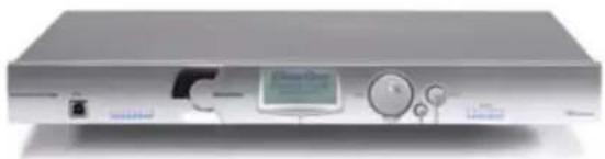
natural_image
Front view of a silver electronic device with control knobs and a central display (no visible text or symbols)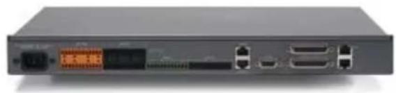
natural_image
Front view of a black network switch device with ports and connectors (no visible text or symbols)The successor to the industry-leading XAP® 800. The 880 delivers rich functionality with improved audio performance, enhanced management, and simplified configuration for audio conferencing and sound reinforcement applications.
Advanced Conferencing Feature Set
Next-generation Acoustic Echo Cancellation
Improved duplex performance »
Push-to-talk microphone compatibility »
Next-generation Noise Cancellation•
Adaptive modeling to room ambient noise conditions »
Increased resolution on Microphone Preamp stage
0 - 56dB in 7dB increments »
Pre-AEC routing for sound reinforcement applications
A maximum processing delay of four (4) milliseconds »
Management Improvements
Integrated Ethernet and USB connections »
SNMP and HTML remote management agents with SMTP email alerts »
Web-based user and management control consoles »
Event scheduler »
Diagnostic console »
• Simplified Configuration Software
»Drag & drop A/V and channel objects
Selectable Console views—Unit, Matrix, and Channel »
- Expanded serial command set
Superior Audio Performance
- Next-generation Distributed Echo Cancellation on every microphone input
- First-microphone priority delivers clear audio to the far end
- 20Hz – 22kHz bandwidth for full-range audio response
- AGC & ALC to keep all participants' audio levels balanced and consistent
Configuration Flexibility
- Scalable—link up to 34 Converge Pro units together for up to 96 microphones and 16 telephone lines
- Enhanced expansion bus, featuring 18 mix/minus audio buses for routing between units
- Ten microphone gating groups (four internal & six global) allow separation of microphones into individual mixer gating groups for greater configuration flexibility
- 32 user-programmable presets can each be executed without disturbing other ongoing preset operations
• 255 Macros for customized audio control and configuration using a single command
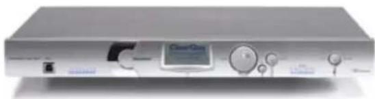
natural_image
Front view of a silver electronic device with control knobs and a central display (no visible text or symbols)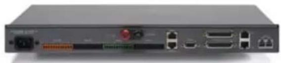
natural_image
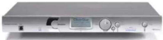
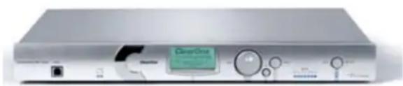
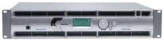
Back view of a network device showing ports, connectors, and a switch (no visible text or labels)The 880T leverages the rich functionality of the Converge Pro 880, and adds a built-in telephone interface and power amplifier for standalone conferencing applications. The 880T also provides industry-leading expansion capabilities, allowing you to connect it with other Converge Pro units for complex installations.
Advanced Telephone Conferencing Feature Set
Signal Processing Improvements
Telephone noise cancellation (receive channel) »
ClearEffect™ wideband emulation for speech enhancement »
Automatic level control (receive channel) »
Caller ID & selectable ringers »
Advanced Conferencing Feature Set
Next-generation Acoustic Echo Cancellation•
Improved duplex performance »
Push-to-talk microphone compatibility »
Next-generation Noise Cancellation
Adaptive modeling to room ambient noise conditions »
Increased resolution on Microphone Preamp stage
0 - 56dB in 7dB increments »
Pre-AEC routing for sound reinforcement applications
A maximum processing delay of four (4) milliseconds »
• Management Improvements
»Integrated Ethernet and USB connections
» SNMP and HTML remote management agents with SMTP email alerts
» Web-based user and management control consoles
»Event scheduler
»Diagnostic console
• Simplified Configuration Software
»Drag & drop A/V and channel objects
Selectable Console views—Unit, Matrix, and Channel »
- Expanded serial command set
Superior Audio Performance
- Next-generation Distributed Echo Cancellation on every microphone input
- First-microphone priority delivers clear audio to the far end
- 20Hz – 22kHz bandwidth for full-range audio response
- AGC & ALC to keep all participants' audio levels balanced and consistent
Configuration Flexibility
- Scalable—link up to 34 Converge Pro units together for up to 96 microphones and 16 telephone lines
- Enhanced expansion bus, featuring 18 mix-minus audio buses for routing between units
- Ten microphone gating groups (four internal & six global) allow separation of microphones into individual mixer gating groups for greater configuration flexibility
• 32 user-programmable presets can each be executed without disturbing other ongoing preset operations
• 255 Macros for customized audio control and configuration using a single command
natural_image
Front view of a silver electronic device with control knobs and a central display (no visible text or symbols)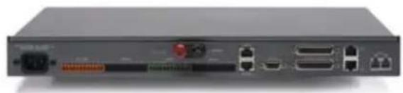
natural_image
Back view of a network switch device showing ports, connectors, and a USB port (no visible text or labels)The successor to the industry-leading XAP 400. The 840T provides the same rich feature set as the 880T, complete with a built-in telephone interface and power amplifier for standalone conferencing applications. For large venues, the 840T also provides industry-leading expansion capabilities via ClearOne's expansion bus technology.
Advanced Telephone Conferencing Feature Set
Signal Processing Improvements Telephone noise cancellation (receive channel) » ClearEffect™ wideband emulation for speech enhancement » Automatic level control (receive channel) » Caller ID & selectable ringers »
Advanced Conferencing Feature Set
Next-generation Acoustic Echo Cancellation Improved duplex performance » Push-to-talk microphone compatibility » Next-generation Noise Cancellation Adaptive modeling to room ambient noise conditions » Increased resolution on Microphone Preamp stage »0 – 56dB in 7dB increments
- Pre-AEC routing for sound reinforcement applications
» A maximum processing delay of four (4) milliseconds - Management Improvements »Integrated Ethernet and USB connections »SNMP and HTML remote management agents with SMTP email alerts »Web-based user and management control consoles »Event scheduler »Diagnostic console
- Simplified Configuration Software »Drag & drop A/V and channel objects » Selectable Console views—Unit, Matrix, and Channel
- Expanded serial command set
Superior Audio Performance
- Next-generation Distributed Echo Cancellation on every microphone input
- First-microphone priority delivers clear audio to the far end
- 20Hz – 22kHz bandwidth for full-range audio response
- AGC & ALC to keep all participants' audio levels balanced and consistent
Configuration Flexibility
- Scalable—link up to 34 Converge Pro units together for up to 96 microphones and 16 telephone lines
• Enhanced expansion bus, featuring 18 mix-minus audio buses for routing between units - Eight microphone gating groups (four internal & four global) allow separation of microphones into individual mixer gating groups for greater configuration flexibility
- 32 user-programmable presets can each be executed without disturbing other ongoing preset operations
• 255 Macros for customized audio control and configuration using a single command
Converge Pro 8i
natural_image
Front view of a silver electronic device with control knobs and a display (no visible text or symbols)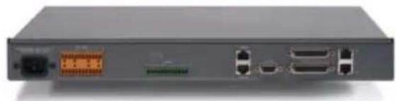
natural_image
Front view of a gray network switch device with ports and connectors (no visible text or labels)An input-only expansion box for the Converge Pro platform. The 8i delivers new economical configuration flexibility. It can be added to 880, 840T, and TH20 systems for additional microphone and line inputs, allowing customers to match the number of inputs and outputs required for specific conferencing and sound reinforcement installations.
Advanced Conferencing Feature Set
- Economical Mic/Line only mixer for large configurations where additional output channels are not required
Next-generation Acoustic Echo Cancellation
Improved duplex performance »
Push-to-talk microphone compatibility »
Next-generation Noise Cancellation
Adaptive modeling to room ambient noise conditions »
Increased resolution on Microphone Preamp stage
0 - 56dB in 7dB increments »
Pre-AEC routing for sound reinforcement applications
A maximum processing delay of four (4) milliseconds »
Management Improvements
Integrated Ethernet and USB connections »
SNMP and HTML remote management agents with SMTP email alerts »
» Web-based user and management control consoles
»Event scheduler
»Diagnostic console
- Simplified Configuration Software
»Drag & drop A/V and channel objects
Selectable Console views—Unit, Matrix, and Channel »
- Expanded serial command set
Superior Audio Performance
- Next-generation Distributed Echo Cancellation on every microphone input
- First-microphone priority delivers clear audio to the far end
- 20Hz – 22kHz bandwidth for full-range audio response
- AGC & ALC to keep all participants' audio levels balanced and consistent
Configuration Flexibility
- Scalable—link up to 34 Converge Pro units together for up to 96 microphones and 16 telephone lines
• Enhanced expansion bus, featuring 18 mix-minus audio buses for routing between units - Ten microphone gating groups (four internal & six global) allow separation of microphones into individual mixer gating groups for greater configuration flexibility
• 32 user-programmable presets can each be executed without disturbing other ongoing preset operations
• 255 Macros for customized audio control and configuration using a single command
natural_image
Front view of a silver electronic device with control knobs and a central display (no visible text or symbols)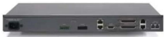
natural_image
Front view of a network switch device showing ports and connectors (no visible text or labels)The successor to the industry-leading XAP TH2, the TH20 enables conference call functionality for Converge Pro installations through the addition of a telephone interface. The TH20 expansion bus allows you to link up to 16 TH20 units together for industry-leading conferencing capability. It also adds two line-level inputs and outputs for increased system capacity.
Advanced Telephone Conferencing Feature Set
Signal Processing Improvements•
Telephone noise cancellation (receive channel) »
ClearEffect™ wideband emulation for speech enhancement »
Automatic level control (receive channel) »
Caller ID »
Selectable ringers »
Increased I/O capabilities•
Two line-level inputs and two line-level outputs »
Audio Expansion bus (E-bus) »
Management Improvements•
Integrated Ethernet and USB connections »
SNMP and HTML remote management agents with SMTP email alerts »
Web-based user and management control consoles »
Event scheduler »
»Diagnostic console
- Simplified Configuration Software
»Drag & drop A/V and channel objects
» Selectable Console views—Unit, Matrix, and Channel
- Expanded serial command set
Superior Audio Performance
- Next-generation Distributed Echo Cancellation on every microphone input
- 20Hz – 22kHz bandwidth for full-range audio response
- AGC on line inputs to keep gain levels balanced and consistent
Configuration Flexibility
- Scalable—link up to 34 Converge Pro units together for up to 96 microphones and 16 telephone lines
- Enhanced expansion bus, featuring 18 mix-minus audio buses for routing between units
- Eight microphone gating groups (four internal & four global) allow separation of microphones into individual mixer gating groups for greater configuration flexibility
- 32 user-programmable presets can each be executed without disturbing other ongoing preset operations
• 255 Macros for customized audio control/configuration with single command execution
natural_image
Front view of a silver electronic device with ports and control knobs (no visible text or symbols)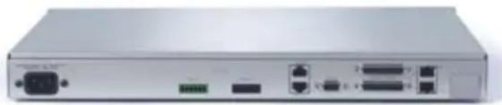
natural_image
Front view of a network switch device showing ports and connectors (no visible text or labels)The VH20 enables VoIP call functionality for Converge Pro installations through the addition of a SIP interface. The VH20 expansion bus allows you to link to other Converge Pro units and up to 16 VH20 units together for industry-leading conferencing capability. It also adds two line-level audio inputs and outputs for increased system capacity.
Advanced Feature Set
SIP Features• Dual Proxy Registration »
Call Features • Speedial/Redial »
Network Features DNS » VLAN Tagging » TLS Encryption for added security »
Superior Audio Performance
• G.722 Wide band audio
- AGC on line inputs to keep gain levels balanced and consistent
Configuration Flexibility
- Scalable: Link up to 34 Converge Pro units together for up to 96 microphones and 16 telephone lines
• Enhanced expansion bus, featuring 18 mix-minus audio buses for routing between units
• 32 user-programmable presets can each be executed without disturbing other ongoing preset operations - 255 Macros for customized audio control/configuration with single command execution
Compatibility/Interoperability
- Cisco
• Avaya - Nortel
- Codian/Tandberg
- Plycom/Accord
- Radvision MCU
natural_image
Front view of a server rack unit with ventilation grilles and control knobs (no visible text or labels)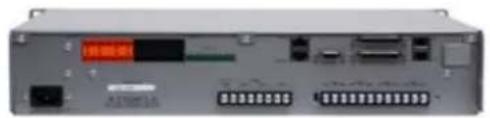
natural_image
Front view of a network equipment unit with ports and connectors (no visible text or symbols)The SR1212A is a 12x12 digital matrix mixer that is the ideal solution for sound reinforcement and room combining applications. In addition to improved audio performance, enhanced management, and simplified configuration, the SR1212 offers industry-leading expansion capabilities to accommodate virtually any size venue.
Advanced Conferencing Feature Set
Increased resolution on Microphone Preamp stage
0 - 56dB in 7dB increments »
Management Improvements
Integrated Ethernet and USB connections »
SNMP and HTML remote management agents with SMTP email alerts »
Web-based user and management control consoles »
Event scheduler »
Diagnostic console »
Simplified Configuration Software
Drag & drop A/V and channel objects »
Selectable Console views—Unit, Matrix, and Channel »
Expanded serial command set
Superior Audio Performance
First-microphone priority delivers clear audio to the far end•
20Hz - 22kHz bandwidth for full-range audio response
AGC & ALC to keep all participants' audio levels balanced and consistent
Configuration Flexibility
- Scalable—link up to 34 Converge Pro units together for up to 96 microphones and 16 telephone lines
- Enhanced expansion bus, featuring 18 mix/minus audio buses for routing between units
- Eight microphone gating groups (four internal & four global) allow separation of microphones into individual gating groups
• 32 user-programmable presets can each be executed without disturbing other ongoing preset operations
• 255 Macros for customized audio control and configuration using a single command
Converge Pro SR1212
natural_image
Front view of a silver electronic device with ports and control knobs (no visible text or symbols)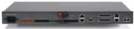
natural_image
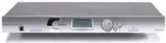
Front view of a black electronic device rear panel with ports and connectors (no visible text or symbols)The successor to ClearOne's PSR1212, the SR1212 is a 12x12 digital matrix mixer that is the ideal solution for sound reinforcement and room combining applications. In addition to improved audio performance, enhanced management, and simplified configuration, the SR1212 offers industry-leading expansion capabilities to accommodate virtually any size venue.
Advanced Conferencing Feature Set
Increased resolution on Microphone Preamp stage
0 - 56dB in 7dB increments »
Management Improvements
Integrated Ethernet and USB connections »
SNMP and HTML remote management agents with SMTP email alerts »
Web-based user and management control consoles »
Event scheduler »
Diagnostic console »
Simplified Configuration Software
Drag & drop A/V and channel objects »
Selectable Console views—Unit, Matrix, and Channel »
Expanded serial command set
Superior Audio Performance
First-microphone priority delivers clear audio to the far end
20Hz - 22kHz bandwidth for full-range audio response
AGC & ALC to keep all participants' audio levels balanced and consistent
Configuration Flexibility
- Scalable—link up to 34 Converge Pro units together for up to 96 microphones and 16 telephone lines
- Enhanced expansion bus, featuring 18 mix/minus audio buses for routing between units
- Eight microphone gating groups (four internal & four global) allow separation of microphones into individual gating groups
- 32 user-programmable presets can each be executed without disturbing other ongoing preset operations
- 255 Macros for customized audio control and configuration using a single command
CUSTOMER SERVICE AND SUPPORT
ClearOne is committed to providing best-in-class customer service and support. If you need assistance installing, configuring, or operating your Converge Pro system, or if you have questions about ClearOne products or services, please contact us at one of the locations listed below. ClearOne also welcomes your comments and suggestions.
ClearOne on the Web
Corporate Website: www.clearone.com
Sales Email: sales@clearone.com
Tech Support Email: tech.support@clearone.com
North America (Worldwide Headquarters)
ClearOne Communications
Edgewater Corporate Park, South Tower
5225 Wiley Post Way, Suite 500
Salt Lake City, Utah 84116 USA
Telephone: 801-975-7200
Fax: 801-977-0087
Toll-Free: 800-945-7730
Tech Support: 800-283-5936
Latin America
Telephone: 801-975-7200
Fax: 801-977-0087
Sales Email: sales@clearone.com
Tech Support Email: tech.support@clearone.com
EMEA
Telephone: 44 (0) 1189 036 053
Sales Email: sales@clearone.com
Tech Support Email: tech.support@clearone.com
Asia-Pacific/Japan/Oceania
Telephone: 801-303-3388
Sales Email: sales@clearone.com
Tech Support Email: tech.support@clearone.com
PRODUCT REGISTRATION
Register your Converge Pro product(s) online at http://www.clearone.com/support/registration.php?content=main.
Registering your Converge Pro product(s) enables ClearOne to provide you with better technical assistance, and to notify you of important information regarding your Converge Pro product including available upgrades, technical bulletins, and new product information.
WARRANTY INFORMATION
ClearOne Communications, Inc. warrants that this Converge Pro product is free of defects in both material and workmanship. For complete warranty information including length, coverage, and limitations, visit http://www.clearone.com/support/warranty.php?content=main
OPERATING REQUIREMENTS
Power
Converge Pro devices automatically accommodate voltages of 100–240 VAC, 50/60 Hz, 15 W.
Telephone
Converge Pro devices operate on a standard analog telephone line and connect to the telephone system with a standard RJ-11 modular jack. If you do not have an RJ-11 jack where you want to install your Converge Pro, call your local telephone company for installation. Converge Pro 840T, 880T, 880TA and TH20 can be configured to meet compliance requirements of different countries via the Console software.

WARNING: The country code must be set correctly in Console to ensure that the unit operates properly when connected to the telco network, and that it complies with the country's telco requirements. Changing this code to a country other than the intended country of operation might cause Converge Pro devices to be non-compliant.
Equipment Placement
Converge Pro devices are designed for installation in a standard 19-inch equipment rack.
Environmental
Converge Pro devices are designed to operate at ambient unit temperatures between 14°F (-10°C) and 122°F (50°C).
SYSTEM REQUIREMENTS
The Converge Pro Console software minimum system requirements are:
Supported Operating Systems
Windows XP
Windows 2000•
Windows Vista•
Minimum System Requirements
Processor: 300 MHz Pentium III (or AMD equivalent)
RAM: 256 Megabytes RAM•
Video: 1024x768 SVGA (16 bit)
Hard Drive: 40 Megabytes•
Network: 10/100 Mbps Ethernet
USB Port: Version 1.0•
CD Drive: CD/DVD ROM•
Minimum Software Requirements
Browser: Microsoft Internet Explorer version 4.0 or higher
Adobe Flash: Version 9.0 or higher
Java: Sun Microsystems' Java Runtime Environment version 6.0 or higher
UNPACKING
Use the illustrations below to verify that you received all components for your Converge Pro product. ClearOne is not responsible for product damage incurred during shipment. Inspect your shipment carefully for obvious signs of damage. If the shipment appears damaged, retain the original boxes and packing material for inspection by the carrier, and contact them immediately.
Converge Pro 880 Package Contents

(1) Converge Pro 880 P/N: 910-151-880

(1) Terminal Block Connector, 12 Position (Green)
P/N: 673-017-212
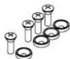
(1) Screw/Washer Kit
P/N: 680-000-001

(3) Terminal Block Connector, 12 Position (Black)
P/N: 673-017-012
natural_image
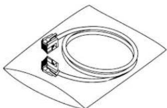
Technical line drawing of a coiled cable or connector with two connectors, placed on a rectangular base (no text or symbols)(1) RJ-45/RJ-45 Patch Cable, 18" P/N: 830-150-004
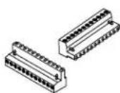
(2) Terminal Block Connector, 12 Position (Orange)
P/N: 673-017-112
natural_image
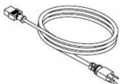
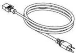
Line drawing of a coiled electrical sensor or probe with two connectors (no text or symbols)(1) Grounded Power Cord, 8' P/N: 699-150-006
natural_image
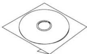
Simple line drawing of a circular ring inside a diamond shape (no text or symbols)(1) Converge Pro Software & Documentation CD P/N: 800-151-881
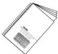
(1) Converge Pro Installation & Operation Manual
P/N: 800-151-880
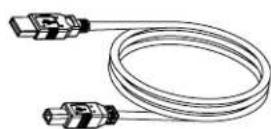
(1) USB Type A to Type B Cable, 6' P/N: 830-153-001
Converge Pro 880T Package Contents

(1) Converge Pro 880T P/N: 910-151-881

(1) Terminal Block Connector, 12 Position (Green)
P/N: 673-017-212
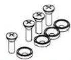
(1) Screw/Washer Kit
P/N: 680-000-001

(3) Terminal Block Connector, 12 Position (Black)
P/N: 673-017-012
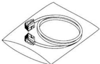
natural_image
Isometric line drawing of a cable with two connectors, enclosed in a diamond-shaped frame (no text or symbols)(1) RJ-45/RJ-45 Patch Cable, 18" P/N: 830-150-004
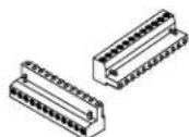
(2) Terminal Block Connector, 12 Position (Orange)
P/N: 673-017-112
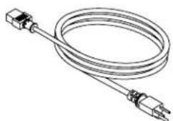
natural_image
Line drawing of a coiled electrical sensor or probe with two connectors (no text or symbols)(1) Grounded Power Cord, 8' P/N: 699-150-006
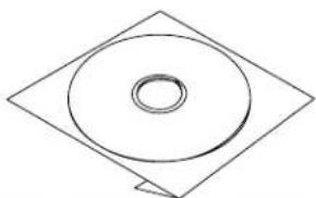
natural_image
Simple line drawing of a circular ring inside a diamond shape (no text or symbols)(1) Converge Pro Software & Documentation CD P/N: 800-151-881
(1) Converge Pro Installation & Operation Manual P/N: 800-151-880
(1) USB Type A to Type B Cable, 6' P/N: 830-153-001
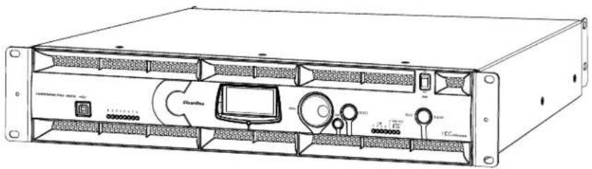
Converge Pro 880TA Packing Contents
natural_image
Technical line drawing of a rack-mounted server unit with ports, cables, and a central monitor (no text or symbols visible)natural_image
Simple line drawing of a circular ring inside a diamond shape (no text or symbols)CD, CONVERGE PRO PRODUCT FAMILY 800-151-881 (QTY 1)
CONN, TERM BLOCK/F 12 POS BLACK
673-017-012 (QTY 2)
natural_image
Illustration of a coiled electrical sensor or probe with two connectors (no text or symbols)PWR CORD, MOLDED 6' BLK 3 COND 699-150-006 (QTY 1)
natural_image
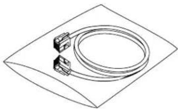
Isometric line drawing of a cable and two connector components on a rectangular base (no text or symbols)CABLE ASSEMBLY, RJ45/RJ45 18" 830-150-004 (QTY 1)
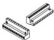
CONN, TERM BLOCK/F 12 POS ORANGE
673-017-112 (QTY 2)
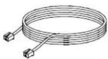
CABLE ASSY, TELEPHONE 12FT.
830-000-012 (QTY 1)
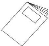
MANUAL, CONVERGE 840T
800-151-880 (QTY 1)
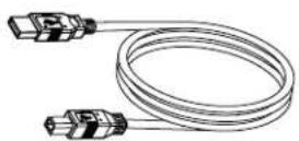
CABLE ASSY, USB A-B TYPE 6FT
830-153-001 (QTY 1)
Converge Pro 840T Package Contents

(1) Converge Pro 840T P/N: 910-151-840

(1) Terminal Block Connector, 12 Position (Green)
P/N: 673-017-212
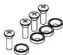
(1) Screw/Washer Kit
P/N: 680-000-001
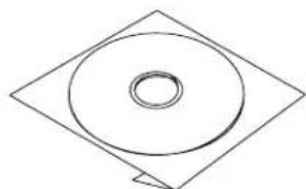
natural_image
Simple line drawing of a circular ring inside a diamond shape (no text or symbols)(1) Software & Documentation CD P/N: 800-151-881
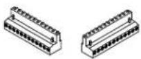
(2) Terminal Block Connector, 12 Position (Black)
P/N: 673-017-012
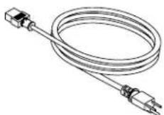
(1) Grounded Power Cord, 8' P/N: 699-150-006
natural_image
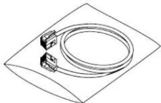
Isometric line drawing of a coiled cable or hose with two connectors, placed on a rectangular base (no text or symbols)(1) RJ-45/RJ-45 Patch Cable, 18" P/N: 830-150-004

(1) Terminal Block Connector, 12 Position (Orange)
P/N: 673-017-112
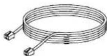
(1) Telephone Cable 12' P/N:830-000-012
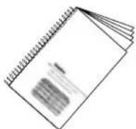
(1) Installation & Operation Manual
P/N: 800-151-880
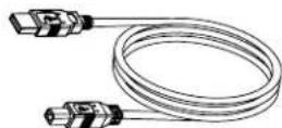
(1) USB Type A to Type B Cable, 6' P/N: 830-153-001
Converge Pro 8i Package Contents

(1) Converge Pro 8i P/N: 910-151-810

(1) Terminal Block Connector, 12 Position (Green)
P/N: 673-017-212
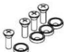
(1) Screw/Washer Kit P/N: 680-000-001
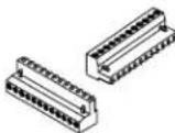
(2) Terminal Block Connector, 12 Position (Orange)
P/N: 673-017-112
natural_image
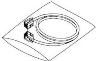
Isometric line drawing of a coiled cable or hose with two connectors, enclosed in a diamond-shaped frame (no text or symbols)(1) RJ-45/RJ-45 Patch Cable, 18" P/N: 830-150-004
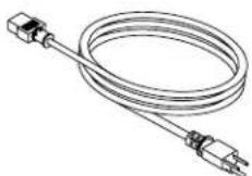
(1) Grounded Power Cord, 8' P/N: 699-150-006
natural_image
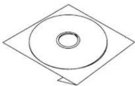
Simple line drawing of a circular ring inside a diamond shape (no text or symbols)(1) Software & Documentation CD P/N: 800-151-881
(1) Installation & Operation Manual
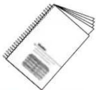
P/N: 800-151-880
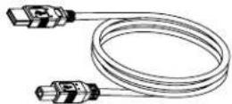
(1) USB Type A to Type B Cable, 6° P/N: 830-153-001

(1) Converge Pro TH20 P/N: 910-151-820
natural_image
Simple line drawing of a circular ring inside a diamond-shaped frame (no text or symbols)(1) Software & Documentation CD P/N: 800-151-881
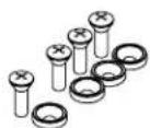
(1) Screw/Washer Kit
P/N: 680-000-001
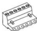
(1) Terminal Block Connector, 6 Position (Black)
P/N: 673-017-006
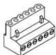
(1) Terminal Block Connector, 6 Position (Green)
P/N: 673-017-016
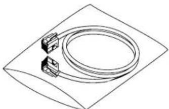
natural_image
Isometric line drawing of a coiled cable or hose component on a square base (no text or symbols)(1) RJ-45/RJ-45 Patch Cable, 18" P/N: 830-150-004
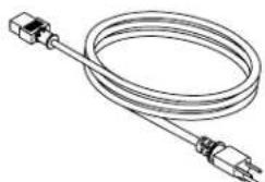
natural_image
Line drawing of a coiled electrical sensor or probe with two connectors (no text or symbols)(1) Grounded Power Cord, 8' P/N: 699-150-006
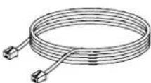
(1) Telephone Cable, 12'
P/N: 830-000-012
(1) Installation & Operation Manual
P/N: 800-151-880

(1) USB Type A to Type B Cable, 6' P/N: 830-153-001

(1) Converge Pro VH20 P/N: 910-151-825
natural_image
Simple line drawing of a circular ring inside a tilted square frame (no text or symbols)(1) Software & Documentation CD P/N: 800-151-881
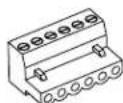
(1) Terminal Block Connector, 6 Position (Black)
P/N: 673-017-006
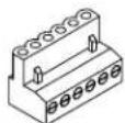
(1) Terminal Block Connector, 6 Position (Green)
P/N: 673-017-016
natural_image
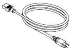
Line drawing of a coiled electrical sensor or probe with two connectors (no text or symbols)(1) Grounded Power Cord, 8' P/N: 699-150-006
natural_image
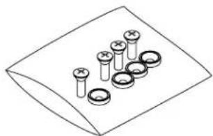
Illustration of multiple screwdrivers arranged on a flat surface (no text or symbols)(1) Screw/Washer Kit P/N: 680-000-001
natural_image
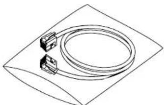
Line drawing of a flexible cable or hose with two connectors, enclosed in a tilted rectangular frame (no text or symbols)(1) RJ-45/RJ-45 Patch Cable, 18" P/N: 830-150-004
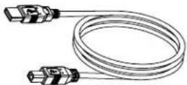
(1) USB Type A to Type B Cable, 6' P/N: 830-153-001
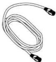
(1) RJ-45/RJ-45 Cable Assembly, 7' P/N: 830-000-023L
Converge Pro SR1212 Package Contents

(1) Converge Pro SR1212 P/N: 910-151-900

(1) Terminal Block Connector, 12 Position (Green)
P/N: 673-017-212
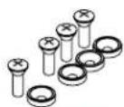
(1) Screw/Washer Kit P/N: 680-000-001
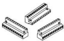
(3) Terminal Block Connector, 12 Position (Black)
P/N: 673-017-012
natural_image
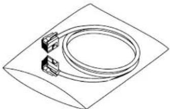
Isometric line drawing of a coiled cable or hose component mounted on a rectangular base (no text or symbols)(1) RJ-45/RJ-45 Patch Cable, 18" P/N: 830-150-004
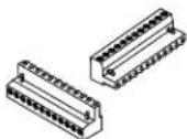
(2) Terminal Block Connector, 12 Position (Orange)
P/N: 673-017-112

natural_image
Line drawing of a coiled electrical sensor or probe with two connectors (no text or symbols)(1) Grounded Power Cord, 8' P/N: 699-150-006
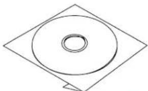
natural_image
Simple line drawing of a circular ring inside a diamond shape (no text or symbols)(1) Converge Pro Software & Documentation CD P/N: 800-151-881
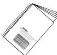
(1) Converge Pro Installation & Operation Manual
P/N: 800-151-880
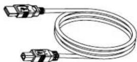
(1) USB Type A to Type B Cable, 6' P/N: 830-153-001
Converge SR 1212A Packing Contents
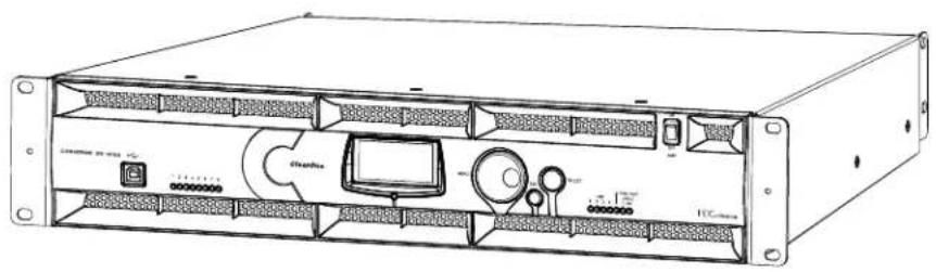
natural_image
Technical line drawing of a rack-mounted server unit with labeled ports and internal components (no readable text or symbols)CONVERGE SR
1212A (QTY 1)

CONN, TERM BLOCK/F 12 POS GREEN
673-017-212 (QTY 1)
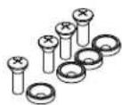
SCREW/WASHER ACC KIT, RACK DECOR 4EA BLK
680-000-001 (QTY 1)

natural_image
Simple line drawing of a circular ring inside a tilted square frame (no text or symbols)CD, CONVERGE PRO PRODUCT FAMILY 800-151-881 (QTY 1)
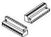
CONN, TERM BLOCK/F 12 POS BLACK
673-017-012 (QTY 2)
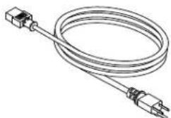
natural_image
Line drawing of a coiled electrical sensor or probe with two connectors (no text or symbols)PWR CORD, MOLDED 6' BLK 3 COND 699-150-006 (QTY 1)
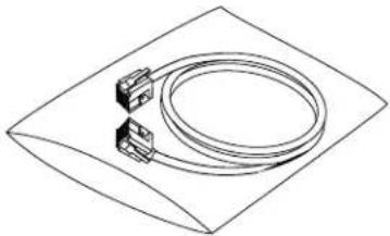
natural_image
Isometric line drawing of a coiled cable or connector with two terminal blocks, enclosed in a diamond-shaped frame (no text or symbols)CABLE ASSEMBLY, RJ45/RJ45 18" 830-150-004 (QTY 1)
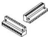
CONN, TERM BLOCK/F 12 POS ORANGE
673-017-112 (QTY 2)
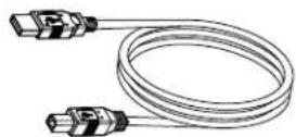
CABLE ASSY, USB A-B TYPE 6FT
830-153-001 (QTY 1)
MANUAL, CONVERGE 840T
800-151-880 (QTY 1)
CONTROLS AND CONNECTIONS
Refer to the following diagrams and descriptions for Converge Pro front panel controls and back panel connectors.
Converge Pro Front Panels
Converge Pro 880 Front Panel

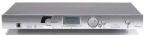
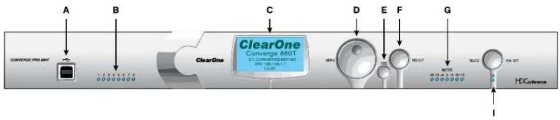
Converge Pro 880T Front Panel
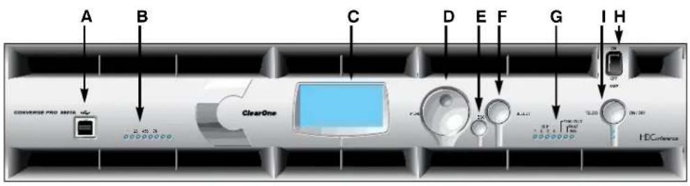
Converge Pro 880TA Front Panel
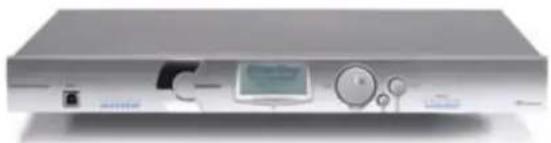
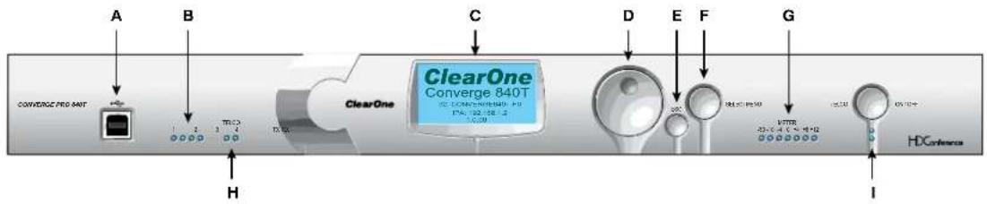
Converge Pro 840T Front Panel
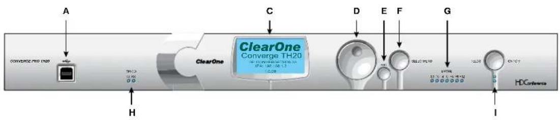
Converge Pro 8i Front Panel

flowchart
graph LR
    A["CONVERGE PRO N"] --> B["Switch"]
    B --> C["ClearOne"]
    C --> D["ClearOne Converge 8i"]
    D --> E["1.009"]
    D --> F["1.009"]
    D --> G["1.009"]
    D --> H["1.009"]
    D --> I["1.009"]
    D --> J["1.009"]
    D --> K["1.009"]
    D --> L["1.009"]
    D --> M["1.009"]
    D --> N["1.009"]
    D --> O["1.009"]
    D --> P["1.009"]
    D --> Q["1.009"]
    D --> R["1.009"]
    D --> S["1.009"]
    D --> T["1.009"]
    D --> U["1.009"]
    D --> V["1.009"]
    D --> W["1.009"]
    D --> X["1.009"]
    D --> Y["1.009"]
    D --> Z["1.009"]
    D --> AA["1.009"]
    D --> AB["1.009"]
    D --> AC["1.009"]
    D --> AD["1.009"]
    D --> AE["1.009"]
    D --> AF["1.009"]
    D --> AG["1.009"]
    D --> AH["1.009"]
    D --> AI["1.009"]
    D --> AJ["1.009"]
    D --> AK["1.009"]
    D --> AL["1.009"]
    D --> AM["1.009"]
    D --> AN["1.009"]
    D --> AO["1.009"]
    D --> AP["1.009"]
    D --> AQ["1.009"]
    D --> AR["1.009"]
    D --> AS["1.009"]
    D --> AT["1.009"]
    D --> AU["1.009"]
    D --> AV["1.009"]
    D --> AW["1.009"]
    D --> AX["1.009"]
    D --> AY["1.009"]
    D --> AZ["1.009"]
    D --> BA["1.009"]
    D --> BB["1.009"]
    D --> BC["1.009"]
    D --> BD["1.009"]
    D --> BE["1.009"]
    D --> BF["1.009"]
    D --> BG["1.009"]
    D --> BH["1.009"]
    D --> BI["1.009"]
    D --> BJ["1.009"]
    D --> BK["1.009"]
    D --> BL["1.009"]
    D --> BM["1.009"]
    D --> BN["1.009"]
    D --> BO["1.009"]
    D --> BP["1.009"]
    D --> BQ["1.009"]
    D --> BR["1.009"]
    D --> BS["1.009"]
    D --> BT["1.009"]
    D --> BU["1.009"]
    D --> BV["1.009"]
    D --> BW["1.009"]
    D --> BX["1.009"]
    D --> BY["1.009"]
    D --> BZ["1.009"]
Converge Pro TH20 Front Panel
Converge Pro VH20 Front Panel
Converge Pro SR1212 Front Panel

flowchart
graph LR
    A["Converge PRD SR1212"] --> B["ClearOne"]
    B --> C["ClearOne Converge SR1212"]
    C --> D["Virtual Device"]
    D --> E["PCDC"]
Converge Pro SR1212A Front Panel
Converge Pro Front Panel Control Descriptions
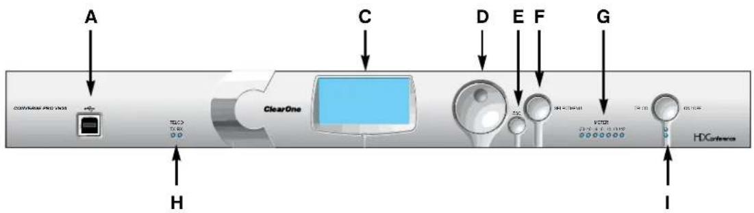
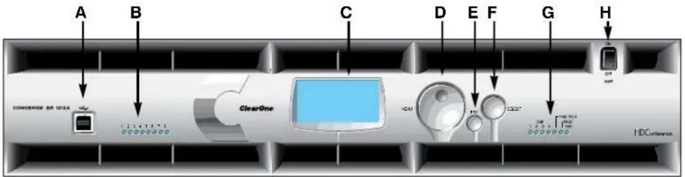
A. USB Type B Port: Provides convenient front panel connectivity for laptops and PCs.
B. Microphone-On LEDs: Indicate microphone gate status and mute state.
C. LCD Display: Shows model number, unit name, IP address, firmware version, menu pages, menu options, configuration settings, and parameter values.
D. Menu Dial: Navigates the Converge Pro LCD programming menu and enables you to modify basic configuration settings.
E. ESC Button: Returns you to the previous screen on the LCD display.
F. Select Button: Displays the Converge Pro LCD programming menu and selects the highlighted option.
G. LED Bar Meter: Displays the audio level of a selected input, output, processing, or fader channel. Default meters: 880-Output 12, 880T-Output 12, 840T-Output 8, 8i-Mic 1, TH20-Telco Tx, VH20-VolP Tx, SR1212-Output 12.
- AMP Fault Indicator LEDs(880TA, SR 1212A): Indicates amplifier faults:
» 1-4 indicates clip
» 5 indicates thermal overload
» 6 indicates fault
» 7 indicates fan on/off
- Telco/VoIP Tx Rx Indicators (840T, TH20, VH20): Indicates transmit and receive activity during Telco/VoIP calls.
H. Amplifier On/Off Switch (880TA, SR 1212A): Turns power to the amplifiers on or off.
NOTE (880TA, SR 1212A): This does NOT disconnect power from the AC mains. To disconnect unit power from the mains, disconnect the unit's power cord from the mains socket. To reconnect power, plug the unit's power cord into the mains socket following all safety instructions and guidelines.
I. Telco On/Off Button & LEDs: This button connects/disconnects the communications line attached to the device while the LEDs indicate the connection status of the attached line (840T, TH20, VH20 (VoIP only), 880T, 880TA).
Converge Pro Rear Panels
Converge Pro 880 Rear Panel

Converge Pro 880T Rear Panel

Converge Pro 880TA Rear Panel
Converge Pro 840T Rear Panel

Converge Pro 8i Rear Panel

Converge Pro TH20 Rear Panel

Converge Pro VH20 Rear Panel
Converge Pro SR1212 Rear Panel

Converge Pro SR1212A Rear Panel
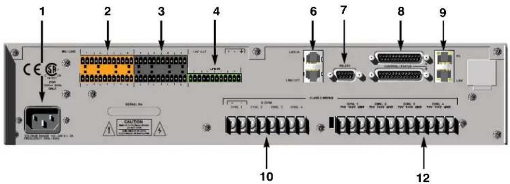
Converge Pro Rear Panel Connectors
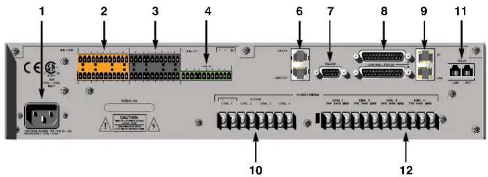
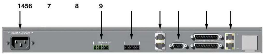
- AC Power: IEC connector, 100 – 240VAC auto-adjusting, 50/60Hz.
Warning: This equipment must be connected to an AC mains socket outlet with a protective earthing connection. The third prong of this connector (ground) is an important safety feature. Do not attempt to disable this ground connection by using an adaptor or other method.
- Mic/Line Inputs: Mini-terminal push-on block connector for any combination of microphone and/or line level inputs. (Converge Pro 880: 8 inputs. Converge Pro 880T: 8 inputs. ConvergePro 880TA: 8 inputs. Converge Pro 840T: 4 inputs. Converge Pro 8i: 8 inputs. Converge Pro TH20, VH20: 0 inputs. Converge SR 1212: 8 inputs. Converge SR 1212A: 8 inputs.)
- Line Outputs: Mini-terminal push-on connector for line-level outputs (880, 880T, 880TA, 840T, SR 1212, SR 1212A).
- Line Inputs: Mini-terminal push-on block connector for line level inputs only. (Converge Pro 880: 4 inputs. Converge Pro 880T: 4 inputs. Converge Pro 880TA: 4 inputs. Converge Pro 840T: 4 inputs. Converge Pro 8i: 4 inputs. Converge Pro TH20, VH20: 2 inputs. Converge SR 1212: 4 inputs. Converge SR 1212A: 4 inputs.)
- Line Outputs: Mini-terminal push-on block connector for line-level outputs (880, 880T, 840T, TH20, VH20, SR1212).
- Link In and Link Out Ports: Two RJ-45 E-bus (expansion bus) connectors used to connect multiple Converge Pro units together to create a site. You can connect up to twelve Converge Pro 840T/880/880T/880TA/8i/SR 1212/SR 1212A units, up to 16 Converge Pro TH20/VH20 units, or any combination thereof, where the total number of microphone inputs does not exceed 96. Maximum cable length is 200 feet using Category 5 unshielded twisted pair cable.

WARNING: Use the Link In and Link Out ports with Converge Pro Devices ONLY. Connecting ANY other devices to the Link In and Link Out ports, including ClearOne XAP or PSR1212 products, or Power Over Ethernet (PoE) devices, will result in severe equipment damage.
- RS-232 Serial Port: Female DB9 connector for connecting to a laptop, computer, or remote control serial devices (such as AMX and Crestron controllers).
NOTE: Converge Console software cannot connect via the RS-232 port; use USB or Ethernet. - Control/Status A and B Ports: Two female DB25 connectors used for GPIO interactions between Converge Pro devices and external control devices (such as wall switches and push-to-talk microphones). This enables external devices and controller software to access the Converge Pro command set, including common functions such as volume control, muting, room combining, and preset changes.
- PC and LAN Ethernet Ports: Two RJ-45 10/100Mbps auto-sensing Ethernet ports. The LAN port connects Converge Pro devices to a network. The PC port provides a pass-through network connection for use with a standard (not crossover) patch cable. The LEDs adjacent to each port indicate connection status and packet traffic activity.
- Speaker Posts (880T, 840T)/Amplifier Terminal Block (880TA, SR1212A):
- 880T, 840T -- Two post/banana plug connectors used to connect an external speaker (4Ω – 16Ω). Internal power amplifiers eliminate the need for an external power amplifier.
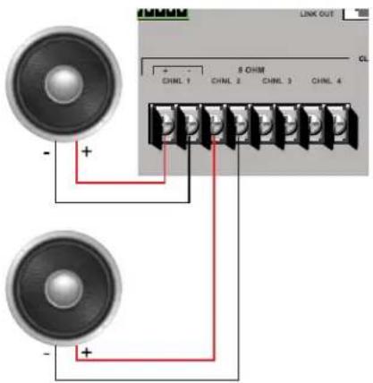
- 880TA, SR 1212A -- 8 speaker terminals used to connect an external speaker (8Ω). Four, 35 Watt internal power amplifiers eliminate the need for an external power amplifier.
NOTE: To reduce risk of electrical shock and damage to equipment, never connect wiring or external equipment while the amplifier is power is on. Class 2 wiring is required. Maintain the correct polarity (+/-) on output connectors. (For example: Channel 1 positive (+) speaker lead connects to amplifier's channel 1 positive terminal. Channel 1 negative (-) speaker lead connects to amplifier's channel 1 negative terminal. Repeat this procedure for each channel.
- Telco Line and Telco Set Ports: Two RJ-11 connectors telephone ports. The Telco Line port connects an analog telephone line to Converge Pro devices. The Telco Set port provides a pass-through connection for telephone handsets (880TA, 880T, 840T, TH20).
NOTE: The Telco Set port is not available for use when the telephone hybrid is off-hook.
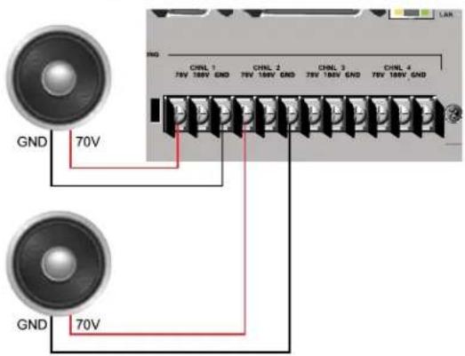
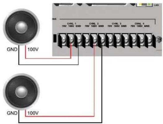
- Amplifier Terminal Block (880TA, SR 1212A): 12 speaker terminals used to connect an external speaker (70/100 v). Four, 35 Watt internal power amplifiers eliminate the need for an external power amplifier.
NOTE: To reduce risk of electrical shock and damage to equipment, never connect wiring or external equipment while the amplifier is power is on. Class 2 wiring is required. Maintain the correct polarity on output connectors. (For example: Channel 1 70/100V speaker lead connects to amplifier's channel 1 70V or 100V terminals. Channel 1 GND (or Common) speaker lead connects to amplifier's channel 1 GND terminal. Repeat this procedure for each channel.
CHAPTER 2: EXPANSION BUS & LCD PROGRAMMING
EXPANSION BUS
The Expansion Bus (E-bus) allows you to connect multiple Converge/Converge-Pro units together to create powerful audio and conferencing solutions for any size venue. The E-bus is a proprietary digital audio bus that provides control and audio data links between devices.
Expansion Bus Connections
Using the E-bus Link In and Link Out ports, you can connect up to 34 Converge Pro 880/880T/880TA/840T/8i and Converge SR 1212/SR 1212A units, and up to 16 Converge Pro TH20 and VH20 units, where the total number of microphone inputs does not exceed 96.
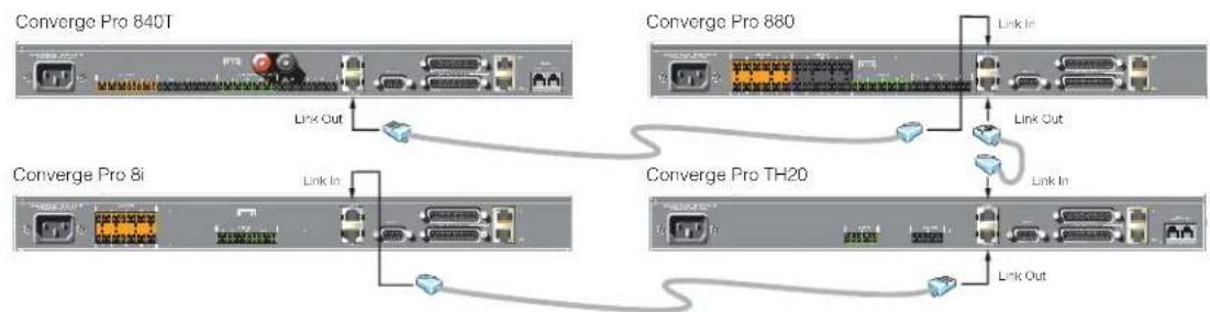
Connect units in daisy-chain fashion (as shown below) using the 18" straight-through patch cable included with each unit (Part # 830-150-004). For larger distances between units, use CAT 5 twisted pair cable with RJ-45 connectors. The maximum cable length between connected units is 200 feet (61 meters).
flowchart
graph TD
    A["Converge Pro 840T"] -->|Link Out| B["Converge Pro 880"]
    B -->|Link In| C["Converge Pro TH20"]
    C -->|Link Out| B
    B -->|Link In| D["Converge Pro 8i"]
    D -->|Link In| C
    C -->|Link Out| E["Converge Pro TH20"]
Audio and Control Buses
The E-bus allows audio routing between source devices and destination devices on the E-bus network. The E-bus contains 18 independent digital audio buses labeled I–Z, which can route mic or line inputs in any combination across the E-bus network. The E-bus also contains four PA adapt/acoustic echo cancellation reference buses, six global gating buses, and one control bus.
S-Z Buses: These eight buses are line input mixer buses. They are used to route auxiliary audio, such as from a CD player or VCR, to and from other units on the network. These buses are also used as mic mixer buses when NOM count is not required.
I-R Buses: These ten audio buses are generally used for routing microphone audio between Converge/Converge Pro devices. Information about the number of gated microphones (NOMcount) and other relevant information for the microphone mixers are tracked for microphones routed to these buses. By default, all microphones are routed to the O bus.
PA Adapt/Acoustic Echo Cancellation Reference Buses: These buses allow an input from a Converge/Converge Pro device to reference an output on another linked device for AEC and PA Adaption. See AEC Reference/PA Adapt Reference and AEC for more information.
Global Gating Groups A-F: These buses are microphone gating groups that support first-mic priority, maximum number of mics, etc. and work across all linked Converge/Converge Pro devices. Unlike the audio buses, they contain only mic status and gate parameters. See the Gating and Gating Grouptopics for more information.
Control Bus: The control bus is an independent channel from the E-bus's audio channel. This allows control information to pass even if the units are not using the audio link. All models support the use of the Converge/Converge Pro serial command set through the control bus.
DEVICE IDS
Device IDs provide unique identifiers for all units that are linked together using the E-bus. After making Expansion Bus connections, you must set a unique Device ID number for all units of the same Device Type on the E-bus.
Device Types and IDs
Device Types and Device IDs by model are as follows:
| Model Device Type Device ID Range | ||
| 880 1 0-B | ||
| TH20 2 0-F | ||
| VH20 E 0-F | ||
| 840T 3 0-B | ||
| 8i A 0-B | ||
| 880T D 0-B | ||
| 880TA H 0-B | ||
| SR 1212 G 0-B | ||
| SR 1212A | I | 0-B |
NOTE: All models ship from the factory with a default DID of 0.
Assigning Device IDs
Use the following procedure to assign device IDs using the front panel controls:
- Press the Select button on the front panel. The Converge Menu appears.
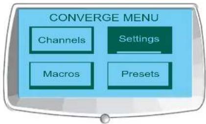
- Use the Menu Dial to highlight the Settings menu. Press the Select button. The Settings menu appears.
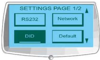
- Use the Menu Dial to highlight DID. Press the Select button. The Device ID menu appears.
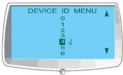
- Use the Menu Dial to highlight the desired value. Press the Select button to select it.
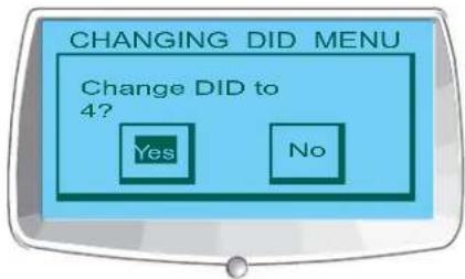
- The Change DID Menu prompt appears. Choose Yes to set the selected DID value, or No to return to the Device ID menu.
- Press Esc until to return to the Settings menu.
Repeat this process for each device on the E-bus network.7.
NOTE: You can also set Device IDs in the Unit Properties screen in Console (when disconnected). However, DID assignments made in Console must match the DID assignments made using the front panel.
LCD PROGRAMMING OVERVIEW
LCD Programming allows you to make simple configuration adjustments using front panel controls (shown below).
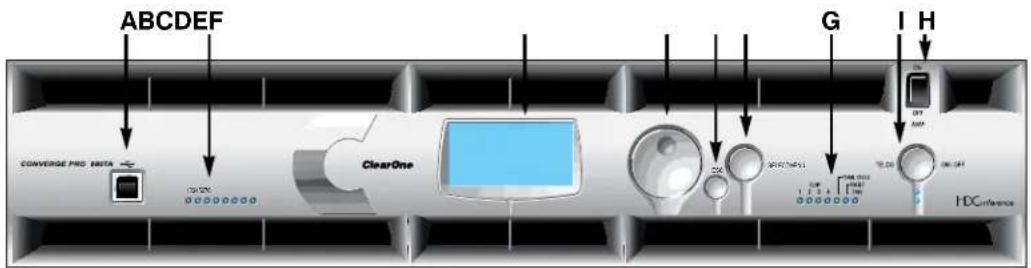
A. USB Type B Port: Provides convenient front panel connectivity for laptops and PCs.
B. Microphone-On LEDs: Indicate microphone gate status and mute state.
C. LCD Display: Shows model number, unit name, IP address, firmware version, menu pages, menu options, configuration settings, and parameter values.
D. Menu Dial: Navigates the Converge Pro LCD programming menu and enables you to modify basic configuration settings.
E. ESC Button: Returns you to the previous screen on the LCD display.
F. Select Button: Displays the Converge Pro LCD programming menu and selects the highlighted option.
G. LED Bar Meter: Displays the audio level of a selected input, output, processing, or fader channel. Default meters: 880-Output 12, 880T-Output 12, 840T-Output 8, 8i-Mic 1, TH20-Telco Tx, VH20-VolP Tx, SR1212-Output 12.
- AMP Fault Indicator LEDs(880TA, SR 1212A): Indicates amplifier faults:
1-4 indicates clip »
5 indicates thermal overload »
6 indicates fault »
7 indicates fan on/off »
- Telco/VoIP Tx Rx Indicators (840T, TH20, VH20): Indicates transmit and receive activity during Telco/VoIP calls.
H. Amplifier On/Off Switch (880TA, SR 1212A): Turns power to the amplifiers on or off.
NOTE (880TA, SR 1212A): This does NOT disconnect power from the AC mains. To disconnect unit power from the mains, disconnect the unit's power cord from the mains socket. To reconnect power, plug the unit's power cord into the mains socket following all safety instructions and guidelines.
I. Telco On/Off Button & LEDs: This button connects/disconnects the communications line attached to the device while the LEDs indicate the connection status of the attached line (840T, TH20, VH20 (VoIP only), 880T, 880TA).
In addition to making configuration adjustments from the front panel, you can also run macros and execute presets. For more information on using front panel controls, see Controls and Connections.
Adjusting LCD Menu Parameters
Use the following procedure to adjust LCD Menu parameters:
-
Press the Select button to access the Converge Menu.
-
Scroll to the parameter you want to adjust using the Menu Dial.
-
Press the Select button to select the parameter. The parameter will stop flashing when selected.
-
Select the value for the parameter using the Menu Dial.
-
Press the Select button to save the parameter value. To discard the change and return to the previous menu, press the Esc button.
NOTE: Use the Console software in Configuration Mode for advanced configuration tasks.
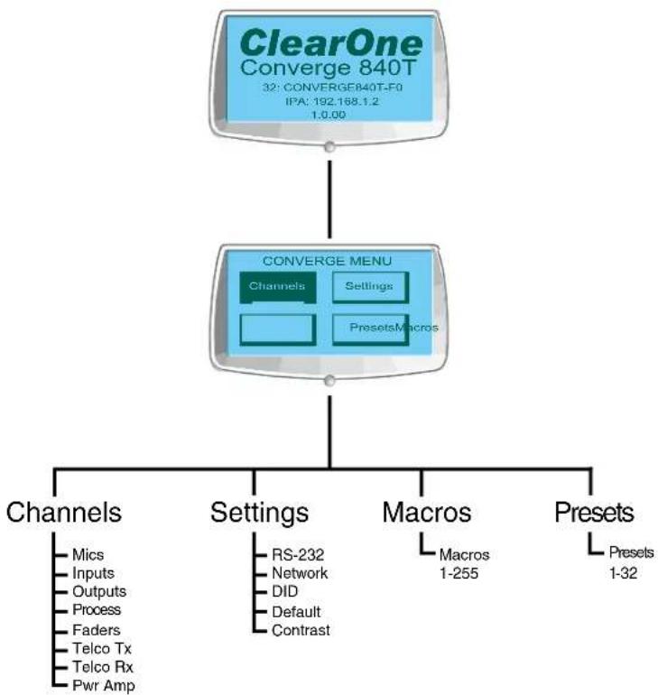
LCD Menu Tree
flowchart
graph TD
    A["ClearOne Converge 840T\n32: CONVERGE840T-F0\nIPA: 192.168.1.2\n1.0.00"] --> B["CONVERGE MENU\nChannels\nSettings\nPresets\Macros"]
    B --> C["Channels"]
    B --> D["Settings"]
    B --> E["Macros"]
    B --> F["Presets"]
    C --> G["Mics\nInputs\nOutputs\nProcess\nFaders\nTelco Tx\nTelco Rx\nPwr Amp"]
    D --> H["RS-232\nNetwork\nDID\nDefault\nContrast"]
    E --> I["Macros\n1-255"]
    F --> J["Presets\n1-32"]
As shown above, the main menus on the LCD display are:
Channels•
Settings•
Macros•
Presets
LCD Default Display
When you power up a Converge/Converge Pro unit, the LCD display reads Initializing. If an error occurs, contact ClearOne Technical Support. When initialization is complete, ClearOne Converge[Model Number] appears on the LCD panel, along with the device type, device ID, device name, IP address, and firmware revision level as shown below.
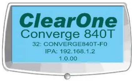
Model
DeviceType, ID, Name
IP Address
Firmware Level
To access the LCD menu, press the Select button. The Converge Menu appears as shown below.
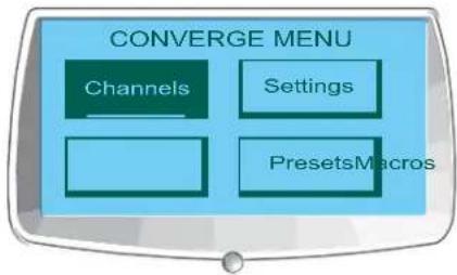
Front Panel Lock
Using Console, you can create a PIN code and lock the front panel to prevent unauthorized access to LCD menu functions. When the lock feature is enabled and the front panel is unlocked, it will automatically re-lock after 3 minutes of inactivity. See the Unit Properties topic for instructions on how to enable the lock feature.
For more information, see the Table of Contents for these related topics:
Macros•
Presets•
Controls and Connections•
Console Configuration Mode
Mic Input Settings•
Line Input Settings•
- LCD Settings Menu
- LCD Macros Menu
- LCD Presets Menu
- Device IDs
- Unit Properties
LCD CHANNELS MENU
The LCD Channels Menu allows you to adjust the gain level and turn mute on or off for all channels.
Accessing the Channels Menu
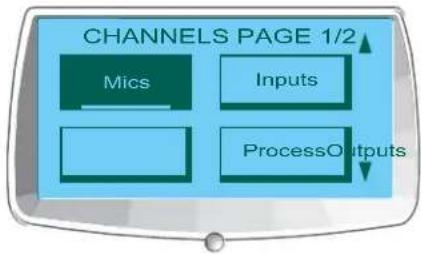
To access the Channels menu, press the Select button on the front panel, use the Menu Dial to select Channels, and press the Select button.
The Channels menu appears as shown below:
flowchart
graph TD
    A["Mics"] --> B["Inputs"]
    B --> C["ProcessOutputs"]
    style A fill:#4CAF50,stroke:#388E3C
    style B fill:#2196F3,stroke:#388E3C
    style C fill:#2196F3,stroke:#388E3C
    subgraph Channels Page 1/2
        direction TB
        M["Mics"] --> N["Inputs"]
        N --> O["ProcessOutputs"]
    end
Channels menu options (i.e. channel types) include:
Mics•
Inputs·
Outputs·
Process•
Faders•
Telco/VoIP TX •
Telco/VoIP RX•
Pwr Amp •
After you select an option, a list of all available channels of that type is displayed. Use the Menu Dial to select the channel you want to configure and press the Select button. The Channels display appears.
Channel Display
The channel display is identical for every channel type, with the exception of the channel ID and channel label, which both vary depending on the channel selected.
As shown below, the display includes a peak-level meter, a peak dB reading, a gain level adjustment box, and a mute selector.
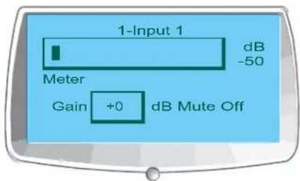
Setting Channel Gain and Mute
The procedure for setting gain and mute is the same for all channel types:
- Use the Menu Dial to highlight Gain or Mute
Press the 2. Select button
Select the desired value using the 3. Menu Dial
- Press the Select button to set the selected value
- Press the Esc button to return to the Channels menu
NOTE: When mute is set to on for a mic input channel, the Microphone-On LED for that channel illuminates red on the front panel.
For more information, see the Table of Contents for these related topics:
LCD Programming Overview
LCD Channels Menu•
LCD Settings Menu•
LCD Macros Menu•
LCD Presets Menu•
Controls and Connections•
Mic Input Settings•
Line Input Settings•
Output Settings•
Process Settings
- Fader Settings
• Telco/VoIP TX Settings
• Telco/VoIP RX Settings - Pwr Amp
LCD SETTINGS MENU
The LCD Settings Menu allows you to configure serial port settings and Device IDs, view network IP settings, change the LCD contrast level, and restore factory default settings for a unit.
Accessing the Settings Menu
To access the Settings menu, press the Select button on the front panel, use the Menu Dial to select Settings, and press the Select button.
The Settings menu appears as shown below:
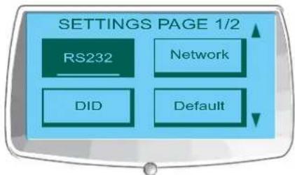
Settings menu options include:
RS-232
- Network
• DID
- Default
- Contrast
Version•
SIP*•
\*VH20 Only
These options are described in the following sections.
RS-232
There are two parameters in the RS-232 menu: Baud Rate and Flow Control. To change these settings, use the following procedure:
- Use the Menu Dial to highlight Baud Rate or Flow Control
Press the 2. Select button
- Select the desired value using the Menu Dial
- Press the Select button to set the selected value
- Press the Esc button to return to the Settings menu
You can also use the Comm tab of the Unit Properties screen to change these settings.
Baud Rate
This parameter allows you to set the baud rate to 9.6kbps, 19.2kbps, 38.4kbps, 57.6kbps, or 115.2kbps. The default is 57.6 kbps. Select the baud rate you want to use, then press the Select button. A message appears on the LCD display indicating the change is in progress, and another indicating the change is complete. When finished, the display returns to the RS-232 sub-menu.
Flow Control (Hardware)
All models use the RTS and CTS pins on the RS-232 port to regulate the transmission and reception of data. You can enable or disable flow control on the front panel, and set the flow control type in the Unit Properties window in Console.
If you select On (default) from the front panel LCD menu, select Hardware as the flow control type in the Unit Properties window. If you disable flow control on the front panel, select None in the Unit Properties window. When None is selected, the unit ignores flow control, and the relies on the connected external control device to ensure data is not lost.
NOTE: ClearOne recommends that you leave Flow Control enabled and connect all DB9 pins to avoid communication errors.
Network
The Network submenu displays the unit name, IP address, Gateway, and Subnet Mask settings for the unit. You cannot change any of these settings from the Network submenu. Use the Unit Properties screen in Console to change these settings.
DID
The DID submenu allows you to select a Device ID for the unit. Select the DID you want to use, press the Select button. Answer Yes to the prompt to change the DID, or No to keep the existing setting.
You can also use the General tab of the Unit Properties screen in Console to change this setting when disconnected from the unit. However, DID assignments made in Console must match DID assignments made using the front panel.
Default
Default restores ALL settings to their factory default values. Answer Yes to the prompt to restore default settings, or No to retain the existing settings.
Contrast
Contrast allows you to change the LCD contrast level. Use the Menu Dial to adjust the contrast level, then press the Select button to save it.
Version
Version displays all relevant version data related to the device.
SIP
SIP Displays which Proxy Settings are currently enabled on the VH20.
For more information, see the Table of Contents for these related topics:
LCD Programming Overview LCD Channels Menu LCD Macros Menu LCD Presets Menu Site Properties String Tab Unit Properties
LCD MACROS MENU
The LCD Macros Menu allows you to run macros from the front panel. To record Macros, use the Macro Tab in Console.
Accessing the Macros Menu
To access the Macros menu, press the Select Button on the front panel, use the Menu Dial to select Macros, and press the Select Button.
The Macro Menu appears as shown below:
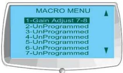
Executing Macros
Use the following procedure to run macros from the front panel LCD display:
- Use the Menu Dial to highlight the macro you want to run Press the 2. Select button
- Answer Yes at the prompt that appears to run the selected macro, or No to cancel.
- Press the Esc button to return to the main LCD menu.
You can also run macros using the Macro tab or the Services menu in Console.
For more information, see the Table of Contents for these related topics:
LCD Programming Overview • LCD Settings Menu LCD Channels Menu LCD Presets Menu Macro Tab
LCD PRESET MENU
The LCD Preset Menu allows you to execute presets from the Converge Pro front panel. To create presets, use Console in Preset Mode.
Accessing the Presets Menu
To access the menu, press the Select button on the front panel, use the Menu Dial to select Presets, and press the Select Button.
The Preset Menu appears as shown below:
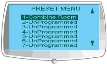
Executing Presets
Use the following procedure to execute presets from the front panel LCD display:
- Use the Menu Dial to highlight the preset you want to execute Press the 2. Select button
- Answer Yes at the prompt that appears to run the selected preset, or No to cancel
- Press the Esc button to return to the main LCD menu
You can also run presets from the Services menu while Console is in Configuration Mode.
For additional information, refer to the Table of Contents for these related topics:
LCD Programming Overview•
LCD Settings Menu•
LCD Channels Menu•
Preset Mode•
Console Overview•
Services Menu Overview•
Configuration Mode Overview
CHAPTER 3: CONVERGE CONSOLE PROGRAMMING
INSTALLING CONVERGE CONSOLE
The Converge Console software is designed for Windows XP and Vista operating systems.
- Ensure that all other programs or applications are closed and disconnect any USB cables from all Converge/Converge Pro devices (you will reconnect them later).
- Insert the Converge/Converge Pro Installation & Documentation CD into the CD or DVD-ROM drive.
- If the Autorun feature is enabled on the PC, the Converge/Converge Pro Installation window opens automatically. Click the Converge Console Software menu option on the left side of the screen to begin installation.
» If Autorun is not enabled, open My Computer navigate to the drive holding the Converge/Converge Pro Installation & Documentation CD. Double-click on the drive icon and launch setup.exe.
-
When the Converge/Converge Pro Installation & Documentation CD window appears, click the Converge Console Software menu option on the left side of the screen.
-
The setup program begins by installing Visual C++ runtime libraries. If prompted, click the Install button (shown below).
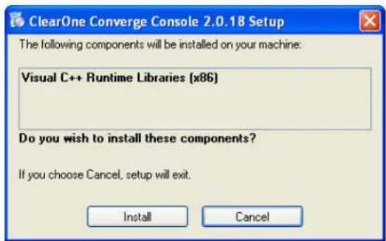
-
When the libraries complete installation, Setup checks the system for Adobe Flash. If Adobe Flash is not installed, Setup starts the Flash installation with a dialog (shown below).
-
Press Yes to install Adobe Flash. Once Flash installs, you will need to repeat this installation procedure starting at step 6 to complete Console installation.
NOTE: Adobe Flash is required to use Console. Clicking No will abort the Flash and Console.
-
The Converge Console Setup Wizard appears. Press the Next button and navigate through the License Agreement and Information screens that appear.
-
At the Select Installation Folder window, choose the directory where you want to install Console. Press the Disk Cost button to analyze available and required free space (if needed).
NOTE: ClearOne recommends that you use the default directory when installing Console.
-
Press the Next button until installation starts.
-
A Windows unsigned driver warning dialog appears as shown below. Click Continue Anyway (Windows XP) or Install this driver software anyway (Windows Vista) to proceed copy Converge/Converge Pro USB drivers onto your system.
![Software Installation The software you are installing has not passed Windows Logo testing to verify its compatibility with Windows XP. [Tell me why this testing is important.] Continuing your installation of this software may impair or destabilize the correct operation of your system either immediately or in the future. Microsoft strongly recommends that you stop this installation now and contact the software vendor for software that has passed Windows Logo testing. Continue Anyway STOP Installation](/content/2026/05/777819/images/006eb6ceb1337283dd7179409654db86a704103a1b02f9aacaeea81d63ee3595.jpg)
NOTE: If you click STOP Installation (Windows XP) or Don't install this driver software (Windows Vista), Windows will terminate USB device driver installation. Console installation will continue to completion, and Console will function properly over IP. However, you will not be able to use Console over USB.
Follow the instructions that appear on-screen to complete installation. 14.
When Console installation is complete, the Converge Console icon appears on your desktop. You can now start Console over IP by double-clicking the icon, or through the All Programs > ClearOne Communications > Converge Console program group in the Windows Start menu.
- To use a USB connection with Console, connect USB cables between the PC and the Converge/Converge Pro device.
NOTE: Windows automatically detects the device and begins the USB device driver installation. This process occurs the first time a new Converge/Converge Pro model is connected to the system, and once when you switch to a different USB port on the system. If you install drivers for a model and subsequently connect another model to the system via USB, Windows will repeat the installation process for the new device type.
- When the Found New Hardware Wizard appears, select the No, not this time radio button. Click Next to begin installation.
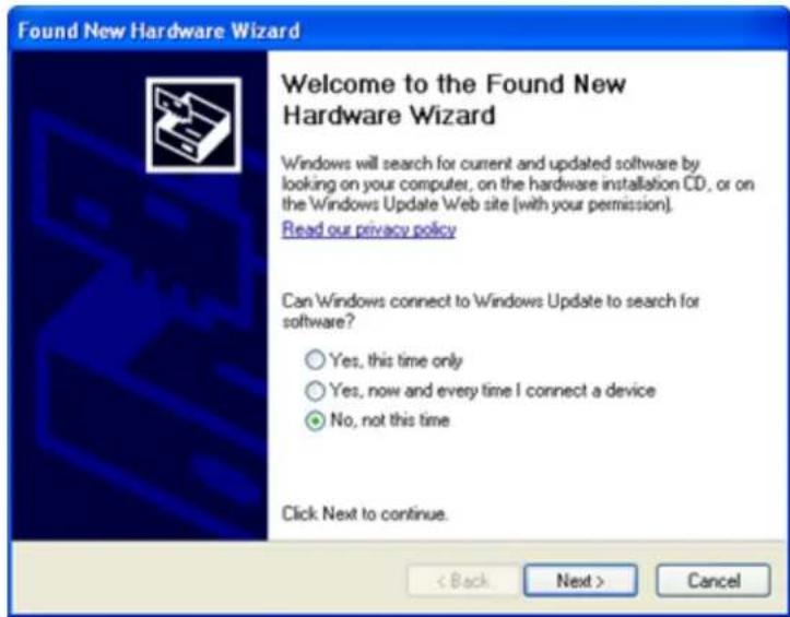
- Select the Install the software automatically radio button in the second screen of the wizard (shown below), then click Next to proceed with installation.
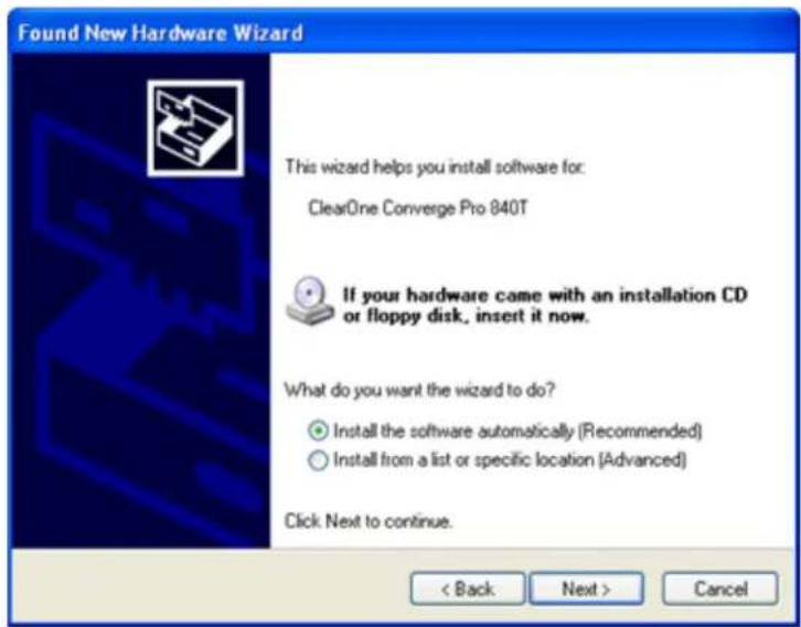
-
When the Windows unsigned driver warning dialog appears, click Continue Anyway (Windows XP) or Install this driver software anyway (Windows Vista) to install the drivers.
-
When the USB driver installation is complete, click Finish to close the wizard.
-
If you will be using IP to run Console, connect Ethernet cables between your LAN and Converge/Converge Pro device(s).
The Console software and your Converge/Converge device(s) are now ready for use. If you experience any problems during installation, contact ClearOne technical support.
CONVERGE CONSOLE OVERVIEW
The Converge Console software provides a powerful, intuitive interface for configuring and controlling your Converge/Converge Pro system. While you can use LCD Programming for simple configuration tasks, you must use Console to configure the advanced settings required to customize units for your application.
Accessing Converge Console
Start Converge Console by double-clicking the desktop icon, or by clicking the Start button in Windows and selecting All Programs > ClearOne Communications > Converge Console > Converge Console from the program list.
After Console loads, you can open an existing Site File from the File menu, or create a new site file by selecting New Site. When a site file is opened, Console displays the Unit Tab as shown below.
Default User ID and Password
Connecting to a site with Console requires a user name and password. The default user name is clearone; the default password is converge.
NOTE: User names and passwords are not case sensitive. ClearOne recommends that you record user names and passwords and store them in a secure place. There is no way to retrieve passwords. If you forget a password, the only way to connect to the device is to Default the unit.
After connecting, you can add/modify user IDs, change passwords, and set access privileges using the Site Properties dialog.
Navigating Converge Console
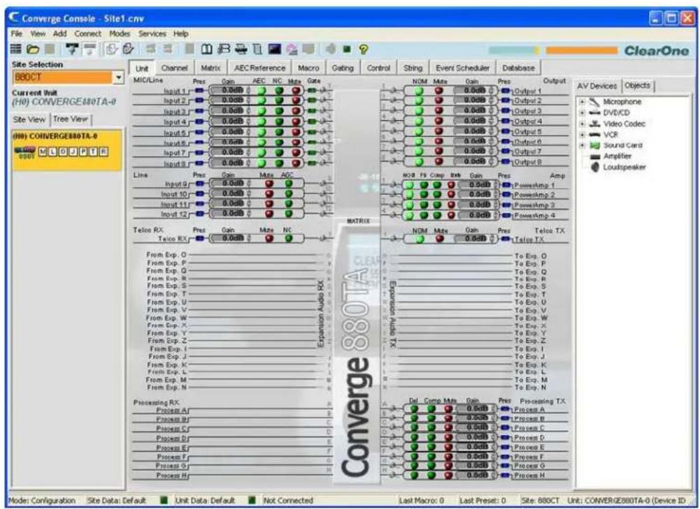
The Console window consists of the components described in the following sections.
Menu Bar
File View Add Connect Modes Services Help
Menus available on the Menu Bar include:
File•
View·
Add·
Connect•
Modes•
Services•
- Help: Opens the context-sensitive help system; provides software and firmware version information.
Button Bar

Controls on the Button Bar include:
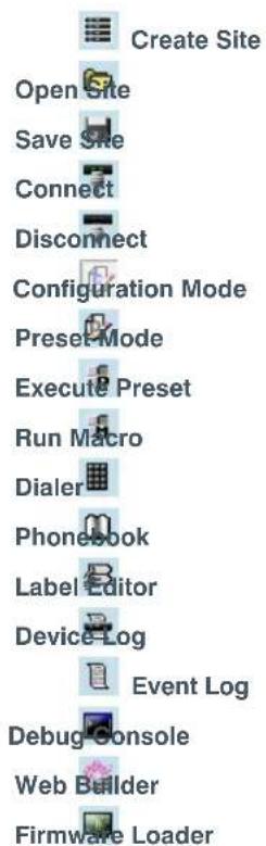

VH20 Unit Properties: (This button is only active when Console is connected to a VH20)

Safety Mute: Toggles Safety Mute on and off. Safety Mute holds all outputs in a muted state.

Signal Generator LED: Flashes green when the signal generator for any unit in the site is turned on.

Help: Opens the context-sensitive help system; provides software and firmware version information.
Tab Bar
| Unit | Channel | Metric | AEC Reference | Macro | Gating | Control | String | Event Scheduler | Database |
Tabs available on the Tab Bar include:
Unit·
Channel•
Matrix•
AEC Reference (PA Adapt Reference for SR 1212/SR 1212A)
Macro
Gating•
Control·
String·
Event Scheduler
Database•
Clicking a tab displays the screen for that tab in the Console Center Pane.
Site Pane
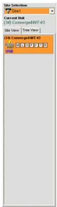
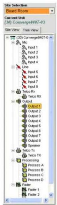
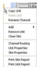
In Configuration Mode, the Site Pane contains the Site Selection drop-down list, Site View tab, and Tree View tab. Right-clicking in either the Site View tab or the Tree View tab brings up a context menu with site, unit, channel, and reporting options applicable to the selected unit type.
In Preset Mode, the Site Pane displays the Current Site, Current Unit, Preset Selection list, and the Preset Name, Description, and Preset Mask entry fields.
Center Pane
The Center Pane displays the screen for the selected Console Tab. As shown above, the default screen is Unit Tab.
Objects Pane

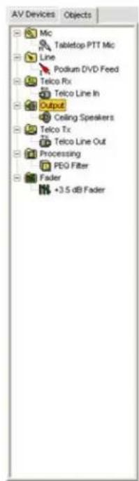
The Object Pane contains the AV Devices tab, which allows you to select from a list of pre-configured device settings and apply them instantly to a channel; and the Objects tab, which allows you to select from a list of custom channel objects and instantly apply them to a specific channel type. AV Devices and channel Objects are stored in the Database.
Status Bar

The Status Bar displays the current Console Mode, as well as connection status, site information, and unit information.
The LEDs in the Status Bar indicate current status as follows:
Clear • (no LEDs illuminated): Not connected
Yellow: • Connecting/pending
Green: • Connected
Red: • Off-line
Purple: • Current with error
Console Modes
Console has two modes: Configuration Mode and Preset Mode. Configuration Mode allows you to configure a wide range of advanced settings for your unit(s). Preset Mode allows you to create presets for specific venues and apply them instantly to Converge/Converge Pro unit(s).
For additional information, refer to the Table of Contents for these related topics:
- LCD Programming
- Site Properties
- Configuration Mode Overview
- Preset Mode Overview
SITE FILE OVERVIEW
Site Files allow you to store configuration settings for one or more units for a specific application or venue. Site files also provide Console with the necessary information to communicate with the Converge/Converge Pro devices using your PC.
Site files are a powerful tool for creating a library of configuration files for specific applications and room types. For example, you can create a baseline site file for divided rooms that specifies mic gating, output crosspoints, AEC, and AGC/ALC, store it on your hard drive, and use the file for other similar installations. This approach allows you to standardize settings across venues.
NOTE: All units ship with a default site configuration file.
Site files also enable you to create users, set passwords, set unit master/slave control status, set up email notification, and configure time/local parameters as described in the Site Properties topic.
Accessing Site Files
To open a Site file, select the File menu in Console.
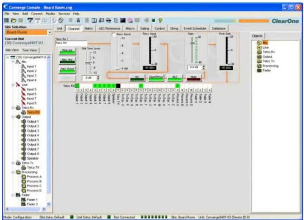
The File menu appears. Select Open Site as shown below.
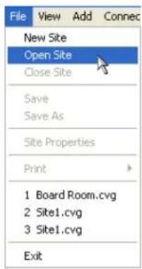
The Open dialog appears as shown below.
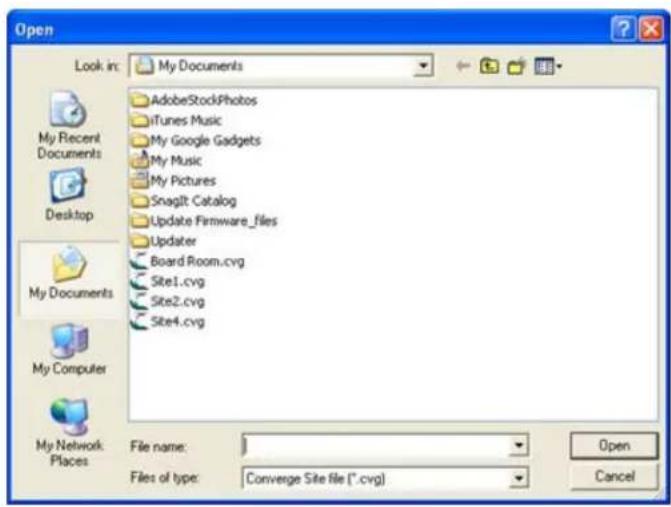
Locate the site file you want to open and click Open. Console opens the site file, and it appears in the Site Selection drop-down list in the Site Pane as shown below. Use the Files of type drop-down list to open G-ware files (.PSR file extension) and convert them to convert G-ware site files to Converge site files.
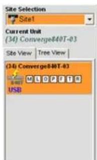
The selected site file is now available for use. You can open up to four site files simultaneously and switch between them using the Site Selection drop-down list.
Saving Site Files
To save the current Site configuration parameters, including any changes made since the active Site file was opened, click the Save button 📋 on the Button Bar, or select Save or Save As from the File menu.
For additional information, refer to the Table of Contents for these related topics:
Create A Site•
Connect to a Site•
Site Properties•
Console Overview•
Configuration Mode Overview•
Channel Tab Overview
Matrix Tab•
CONNECT TO A SITE
Connect To a Site
Click the Connect button 📋 on the Console Button Bar, or select Connect from the Connect Menu. The Connect dialog appears as shown below.
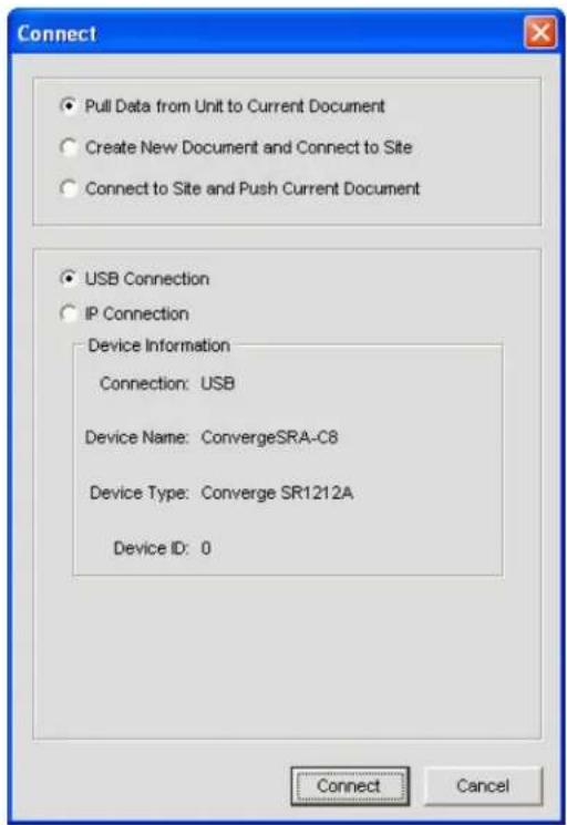
Connection options include:
• To automatically create a new site file, select the Create New Document and Connect to Site radio button
- To pull data from the unit to the current Site File, select the Pull Data from Unit to Current Document radio button (only available if a site file is open)
- To push data from the current site file to the unit, select the Connect to Site and Push Document radio button (only available if a site file is open the unit is added)
- To connect via USB, select the USB Connection radio button
- To connect via IP, select the IP Connection radio button, and select a unit from the Available Addresses drop-down list (or enter an IP address in the Enter Address entry box)
Press the Connect button to connect to the site or Cancel to close the dialog.
NOTE: The default login user name is ClearOne. The default password is Converge. User names and passwords are not case sensitive.
Disconnect from a Site
To disconnect from a site, press the Disconnect button 📋 on the Console Button Bar, or select Disconnect from the Connect menu. Answer Yes to the Confirm dialog that appears, or No to cancel.
For additional information, refer to the Table of Contents for these related topics:
Site File Overview•
Site Properties•
Unit Communication (IP) Settings•
SITE PROPERTIES
Site Files are created and modified using the Site Properties window in Console. Site files contain all information about a particular installation including properties for all units in a site. For more information, see the Site File Overview topic.
Accessing Site Properties
To access the Site Properties window, select the File menu in Console, or right-click anywhere in the Site View or Tree View panes and select Site Properties from the shortcut menu.
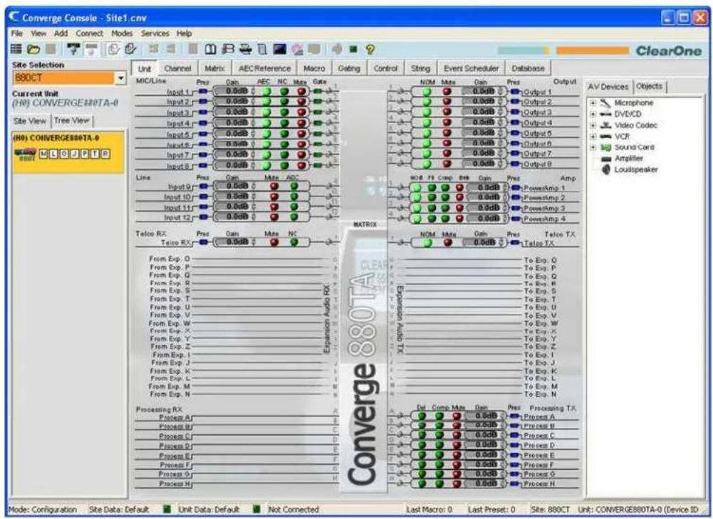
The File menu appears. Select Site Properties as shown below.
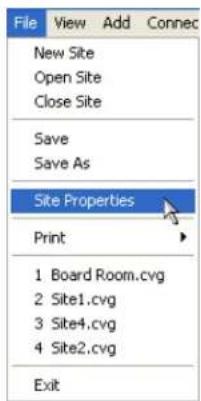
The Site Properties window appears with the General tab selected.
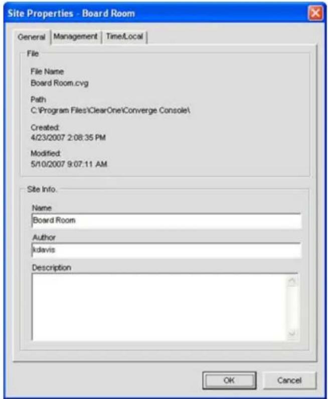
Create A New Site
To create a new site, select New Site from the File menu or by clicking the New Site button on the Console Button Bar. The Site Properties window appears.
NOTE: You must have administrator privileges to connect to units with Console, and to modify user names and passwords. User names and passwords are not case sensitive.
Site Properties are described in the following sections.
Site Properties: General Tab
The General tab of the Site Properties window displays Site file information as shown above. Enter a site name, file
author, and site description in the Site Info section of the tab. Press OK to save the changes, Cancel to close the Site Properties window, or click on the Management or Time/Local tabs to continue site configuration.
Site Properties: Management Tab
The Management tab (shown below) enables you to configure SNMP parameters, email notification settings, as well as user names and passwords.
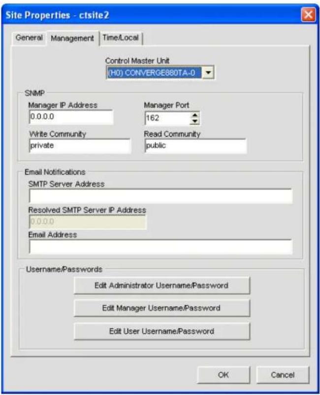
Control Master Unit
All units in the site appear in the Control Master unit list. Selecting a Control Master unit designates that unit to control the SNMP interactions for the entire site across IP-based networks. To use SNMP, the Control Master unit(s) must be connected to the LAN via IP.
All other units in the site are Control Slave units. Control Slave units report events to the Control Master Unit for SNMP reporting and SMTP email notifications.
Serial Control interactions and Audio Control interactions are not affected by a unit's Control Master designation.
NOTE: All units are Control Slave units by default.
SNMP
In the SNMP section, enter the SNMP settings for the site. The Control Master nit uses this information to communicate SNMP events, including events reported by Control Slave nits.
NOTE: The Installation & Documentation CD contains SNMP MIB files for each device type for use with third-party SNMP management software.
Email Notifications
In the Email Notifications section, enter the SMTP Server address in the SMTP Server Address field and the IP address of the server that will receive email notifications in the SMTP Server IP Address field. The recipient's email address in the Email Address field.
User name/Passwords
In the User name/Passwords section, click the button for the user type that you want to create. The Name/Password dialog appears as shown below.
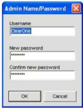
NOTE: The default user name is clearone. The default password is converge. User names and passwords are not case sensitive.
User access privilege levels are as follows:
Administrator• : Full Console and web portal access.
- Manager: Web access to Dialer, Maintenance, Registration, About, and Help pages.
- User: Web access to the Dialer, Registration, About, and Help pages.
Enter the appropriate user information and press OK to save the user information, or Cancel to return to the Site Properties dialog.
Site Properties: Time/Local Tab
The Time/Local tab enables you to configure time settings and specify location information as shown below. As shown below, you can set the date and time manually, synchronize the time with a PC, or use network time servers.
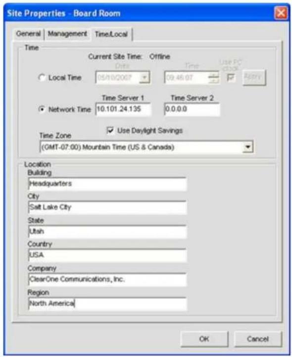
In the Time section of the tab, select Local Time or Network Time for the clock synchronization source.
When Local Time is selected, the Apply button is activated; pressing it updates the date and time on all units in the current site.
When Network Time is selected, you must enter the IP address(es) for the time synchronization server(s). The date and time is updated for all units in the site when you press the OK button, and it is automatically synchronized with the specified server(s).
Enter location information in the Location section of the tab (optional). Press OK to save the site file, or Cancel to close the Site Properties window.
For additional information, refer to the Table of Contents for these related topics:
Site File Overview•
Connect To A Site•
Unit Properties•
Configuration Mode Overview
UNIT PROPERTIES
Unit Properties define properties for a specific Converge/Converge Pro unit. Unit Properties enable you to configure general unit settings such as name, and telephone country code, as well as IP and serial communication settings. Properties that apply to all units in a site are configured using Site Properties.
Accessing Unit Properties
To access the Unit Properties window, right click the unit you want to configure in either the Site View tab or the Tree View tab of the Site Pane in Console.
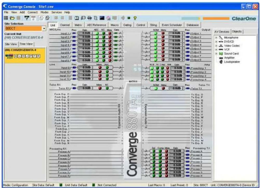
The Site/Unit menu appears. Select Unit Properties as shown below.
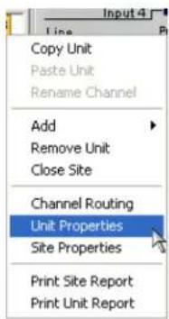
The Unit Properties window appears as shown below.
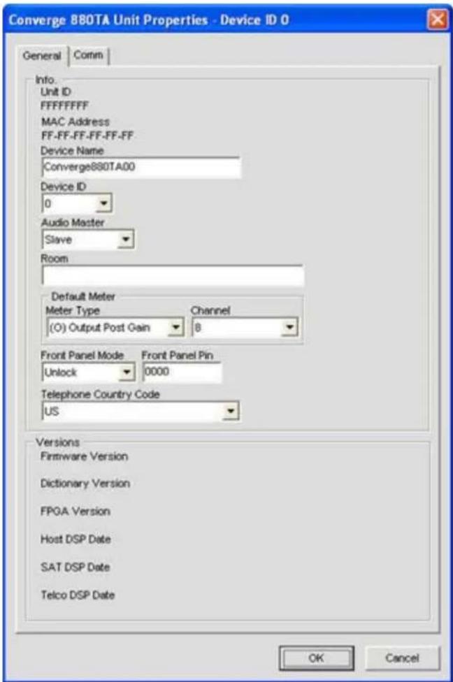
Add A New Unit
To add a unit to a Site, right-click in either the Site View tab or the Tree View tab of the Site View pane, or select the unit type you want to add from the Add menu on the Menu Bar as shown below.
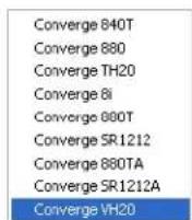
The Unit Properties window appears. Unit Properties settings are described in the following sections.
Unit Properties: General Tab
The Unit ID and MAC Address for the selected unit are automatically displayed at the top of the Info section of the tab. When connected, the firmware version, dictionary version, and DSP date versions are displayed in the Versions section at the bottom of the tab (when connected). These settings cannot be modified.
Device Name
Enter a descriptive name in the Device Name field. Device names are used as network identifier on NetBIOS
networks. They must start with a letter and can contain both letters and numbers, with a maximum length of 15 characters. No special characters are allowed except for “-”.
Device ID
Select a Device ID from the Device ID drop-down list.
Device IDs ensure that Console synchronizes with the proper unit when there are multiple units of the same type in a site. Therefore, each unit of the same type in a site must have a unique Device ID assigned using the front panel LCD Settings menu. All units ship from the factory with a default DID of 0.
Device Types and Device IDs by model are as follows:
| Model Device Type Device ID | ||
| 880 1 0-B | ||
| TH20 2 0-F | ||
| VH20 E 0-F | ||
| 840T 3 0-B | ||
| 8i A 0-B | ||
| 880T D 0-B | ||
| 880TA H 0-B | ||
| SR 1212 G 0-B | ||
| SR 1212A | I | 0-B |
For example, if there are two Converge Pro 880s and one 840T in a site, the 880s must have unique DIDs. They could be assigned DIDs of 0 and 1 respectively, while the 840T could be assigned a DID of 0 without any conflicts.
NOTE: You must disconnect from the site in order to set the Device ID. Press the Disconnect button on the Button Bar.
NOTE: The DID specified in Console MUST match the DID set for that unit in the LCD Settings Menu. Otherwise when you reconnect to the site, Console will correctly recognize the unit with the correct DID, but it also adds a duplicate unit with the incorrect DID.
Audio Master
Select Slave (default) or Master from the Audio Master drop down list. Audio Master units ignore audio from upstream units in a site as shown in the sample stack below.
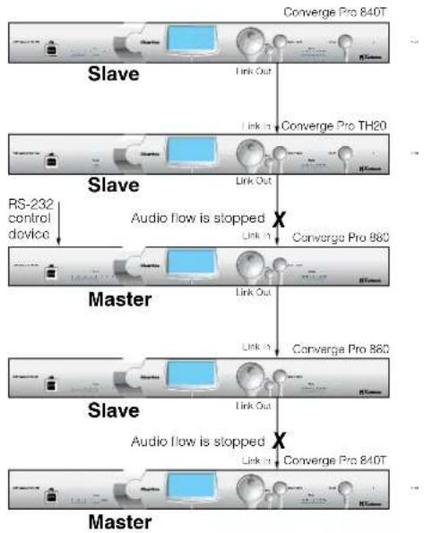
flowchart
graph TD
    A["Slave"] --> B["RS-232 control device"]
    B --> C["Master"]
    C --> D["Slave"]
    D --> E["Master"]
    E --> F["Converge Pro 840T"]
    C --> G["Audio flow is stopped"]
    G --> H["Converge Pro 980"]
    H --> I["Converge Pro 860"]
    D --> J["Audio flow is stopped"]
    J --> K["Converge Pro 840T"]
This prevents audio from being received from units above the master unit in a site. For example, you can configure a site with multiple units for a room-combining application where all units act together when three smaller rooms are combined into a larger room. When the rooms are divided again, the audio from one room will not be available in the other two rooms due to the Audio Master configuration.
In graphic above, the third unit in the network is an Audio Master with an RS-232 control device attached. Audio from the first and second units in the network does not pass beyond the second unit. Likewise the second Audio Master unit in the network does not pass audio from the unit before it. Sites can use multiple RS-232 devices, which you can connect to any unit regardless of Control Slave or Master designations.
Serial control is not affected by Audio Master or Slave designations. Global serial control of the site is maintained by the unit connected to a control device through its RS-232 port, in this case the third unit in the stack, which is also designated as the first Audio Master in the network.
NOTE: A master unit is not required for Converge/Converge Pro sites, and in most installations, all units will be slaves. Also, SNMP Control is not affected by Audio Master designations.
For information about the Link In and Link Out connections used to build sites, see Controls & Connections.
Room
Enter a descriptive name for the room in the Room field.
Default Meter & Channel
Select an input, output, or processing channel to be the Default Meter on the front panel LED Meter when a channel is not specifically selected.
Front Panel Mode & PIN (Front Panel Lock/Unlock)
Select Lock in the Front Panel Mode field to lock the front panel LCD of the unit and require a PIN code to unlock it. Enter the unlock code in the Front Panel Pin field. Select Unlock in the Front Panel Mode field to leave the front panel LCD unlocked.
Telephone Country Code
Select the appropriate Telephone Country Code for your installation (880TA, 880T, 840T, TH20 models only).
Unit Properties: Comm (Communications) Tab
The Comm tab contains IP protocol selection and address settings, as well as serial port configuration settings as shown below.
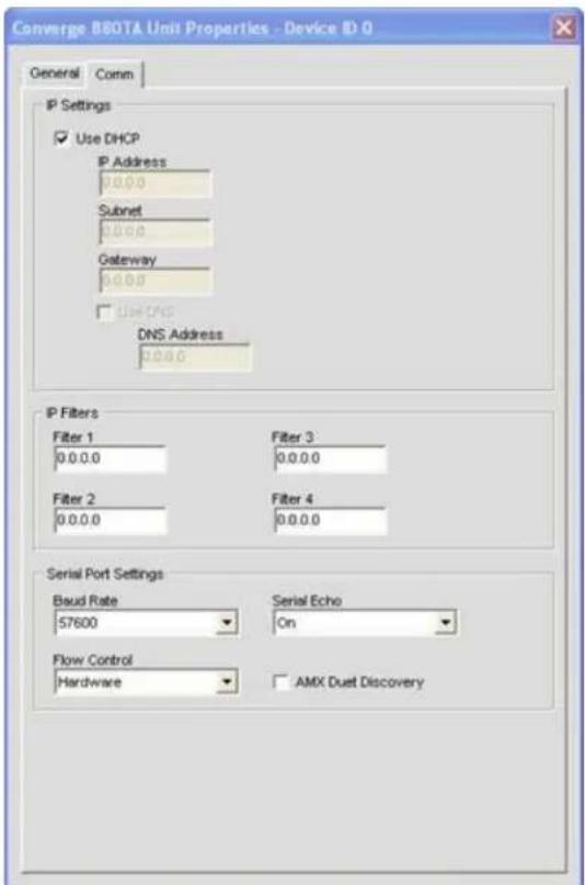
IP Settings
If you want to use DHCP (Dynamic Host Configuration Protocol), select the DHCP checkbox. (Selecting DHCP disables the remaining IP settings.) Otherwise, enter the IP Address, Subnet, and Gateway information, and DNS (Domain Name Server) addresses for your installation. The default is Use DHCP.
IP Filters
Use IP Filters to enter specific IP addresses that will be allowed to connect to the selected unit. You can specify a range of IP addresses by using zeros. For example, entering 192.168.105.0 will allow any IP addresses in the 192.168.105.1 to 192.168.105.254 range to access the unit.
Serial Port Settings
Select the Serial Port settings (Baud Rate and Flow Control) that are appropriate for your installation. Serial Echo enables and disables echo on the serial port. The default for Baud Rate is 57600. The default for Flow Control is Hardware. The default for Serial Echo is On.
When you are finished configuring unit properties, click OK to save the changes, or Cancel to close the Unit Properties window.
AMX Duet Mode
Sets a beacon to signify the device is AMX compatible and looks for new or updated modules on the AMX Web Site. If new or updated modules are available, the user will be prompted to download the module.
CONVERGE PRO VH20 SITE PROPERTIES
Site Properties for the Converge Pro VH20 are accessed identically to any other Converge unit. However, once the Properties, SIP Properties window has launched, several new configuration features are available.
NOTE: The SIP Properties window is also accessible by right-clicking the VH20 icon under Site View and selecting SIP Properties.
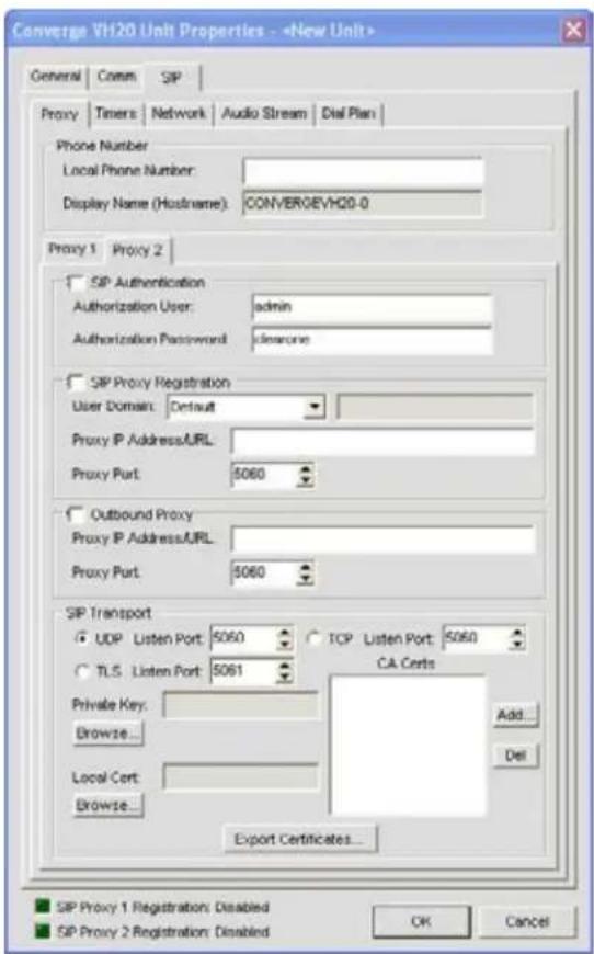
Five tabs contain most of the configuration settings required to customize the Converge Pro VH20. Do not modify these settings unless you have in-depth knowledge of VoIP, SIP and Network functions, setup and protocols. Also,
be sure you have sufficient network privileges and access required to make required changes to your network during setup. If you are unsure, contact your Network Administrator before proceeding.
Proxy
The Proxy tab consists of 6 sections.
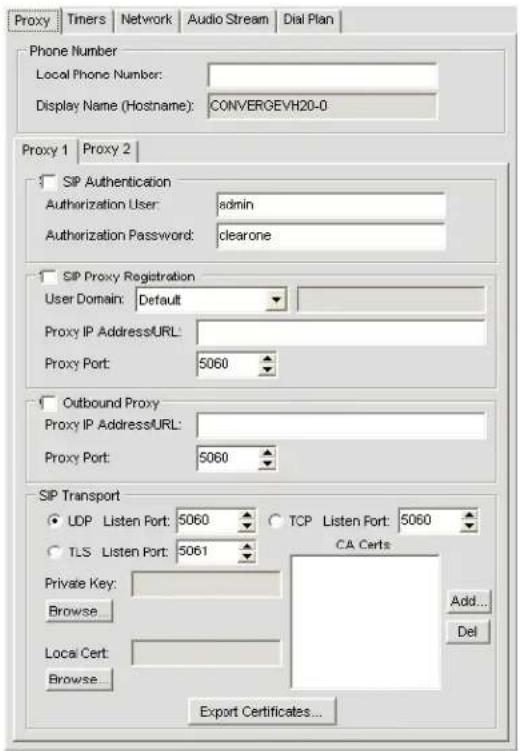
Phone Number
- Displays the local phone number assigned to the specific unit. This number is usually obtained through your Network Administration.
- Display Name (Hostname): The name assigned to the specific unit. This name is configured within the Converge Console software.
Proxy 1, Proxy 2: Proxy 1 and Proxy 2 are identical and used as redundancy items.
SIP Authentication• : Enables SIP Authentication from the Network
Authorization User• : User name assigned for network authorization
Authorization Password• : Password assigned for network authorization
SIP Proxy Registration•
User Domain•
Default·
Proxy•
Domain Name•
Proxy IP Address/URL• : Enter the IP address/URL of the proxy server
- Proxy Port: Enter the port number for the proxy server
- Outbound Proxy: Enable this feature to use a proxy outside or alongside a firewall.
Proxy IP Address/URL• : Enter the IP address/URL of the proxy server
- Proxy Port: Enter the port number for the proxy server
- SIP Transport: Set transport settings here.
- UPD Listen Port: Specify the UPD Listen Port.
• TCP Listen Port: Specify the TCP Listen Port. - TLS Listen Port: Primarily used by Avaya systems, the TLS Listen Port is specified here.
- Private Key: Click the Browse button to upload your Private Key file
- Local Cert: Click the Browse button to upload your Local Certificate file
• CA Certs: Use the Add or Del buttons to add or remove CA Certs
Timers
Timers are used to keep SIP sessions "alive" on the network. Normally, default values are appropriate.
Occasionally your Network Administrator may want to customize the settings. Do not change these settings unless directed to do so.
All Values are in milliseconds unless otherwise noted.
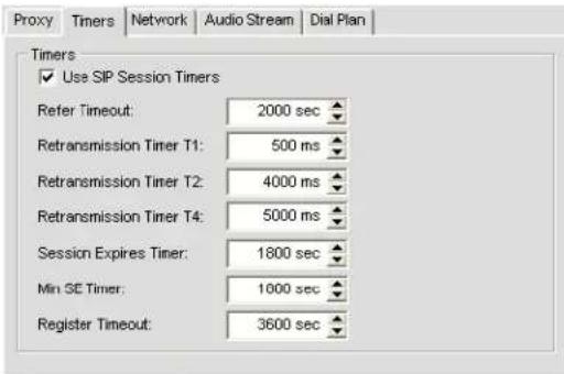
- Use SIP Session Times: This box is checked by default. Removing the check will disable all timers.
Refer Timeout• : Number of ms the server waits for a reply
Retransmission Timers• : Refers to three Timers
T1• : Sets the round-trip time for a packet
- T2: Sets the retransmit time from a non-invite request (REFER, BYE, etc.) and INVITE responses
T4: Sets the total time a given message can be on the network
- Session Expires Timer (Value is listed in Seconds): Default time before the current session expires due to inactivity. This value MUST be greater than the Min SE Timer value.
- Min SE Timer (Value is listed in Seconds): Minimum Session Timer
- Register Timeout (Value is listed in Seconds): The period of time a given device is registered on the network.
Network
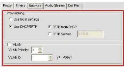
The Network tab allows the user to set basic network settings. Have your Network Administrator modify these settings.
- Provisioning: Provides the VH20 with access to data and network resources by receiving authorization and privileges via resource management.
- Use local settings: The unit uses local settings provided by the server
- Use DHCP/TFTP: User provides settings for the VH20 to gain access to the network
- TFTP from DHCP: TFTP settings are received from the server.
- TFTP Server: User manually enters the IP address of the TFTP Server.
- VLAN: Virtual LAN - A LAN configured through software rather than hardware. Toggling this setting activates the flexibility a VLAN can provide SIP configurations.
• VLAN Priority: Establishes the priority of the ID data coming from this specific unit.
VLAN ID• : Provides the ID number to the specific unit
Audio Stream
The Audio Stream tab contains user configurable settings for the audio stream, encryption, QOS and Codec details. Do not change these settings unless you have detailed knowledge of their purpose, they could dramatically effect call quality and performance.
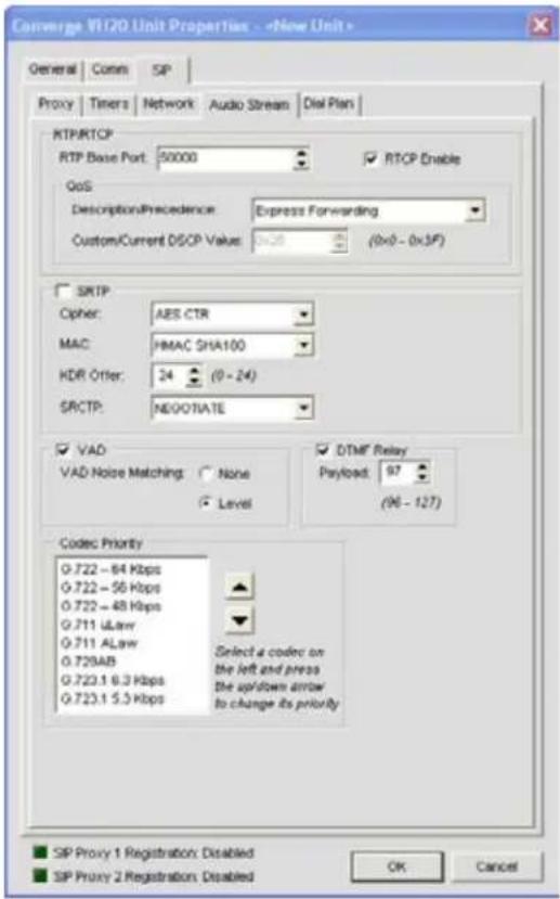
RTP/RTCP·
RTP Base Port• : Port set to transmit RTP data.
RTCP Enable• : Check this box to enable RTCP
- QOS (Quality of Service): QOS is a method in which certain high demand (VoIP, Video, etc.) applications are allowed to maintain a minimum standard of service across a network to avoid unacceptable delays, dropouts or service interruptions during their communications by determining which packets have priority over others.
• Description/Precedence: This drop-down consists of several options.
- Express Forwarding: Default Best Effort•
- Class 1
- Class 2
- Class 3
- Class 4
• Control 6
- Control 7
- Custom: Selecting this option enables Custom/Current DSCP Value. Adjust values to fit QOS needs.
SRTP• : Enabling this setting activates encryption on the VH20
Cipher• : This drop-down selects the cipher to be used.
Null•
AES CTR•
AES F8•
MAC·
Null·
HMAC SHA180•
HMAC SHA13·2
KDR Offer
0-24
- SRCTP:
- Negotiate
- Enable
- Disable
- VAD: Enables "comfort noise" which simulates background noise found in analog phone lines.
• VAD Noise Matching: Settings are None or Level. Default is Level.
- DTFM Relay: This setting emulates normal key tones on a regular phone when used during a call (for example, to select options from an in-call menu).
- Payload:
- Codec Priority: Negotiates the best possible codec for each call that both sides can utilize; both units must have a given codec in order to use it. If the codec is not present, the next one in the list is tried. This process is repeated until the best match is found. To use the Priority setting, follow the instructions given in the tab.
Dial Plan
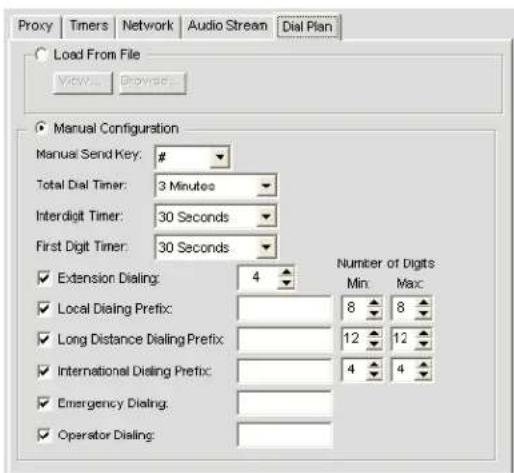
Dial Plan: The Dial Plan consists of numbers and pattern digits for any given telephone number. Since businesses deal in World-wide calling, this should consist of country codes, access codes, area codes and any combination of digits that can be dialed. To accommodate this, Dial Plans are required.
- Load from File
- Manual Configuration
Note: After any changes are made, CLICK OK to save all changes!
For additional information, refer to the Table of Contents for these related topics:
LCD Programming Overview•
LCD Settings Menu•
Site File Overview•
Site Properties•
Connect To A Site•
Preset Mode Overview•
Controls & Connections•
Serial Control•
SNMP Control•
CONFIGURATION MODE OVERVIEW
Converge Console has two modes: Configuration Mode (default) and Preset Mode. Configuration Mode enables you to perform advanced configuration of devices to customize them to your specific application.
Accessing Configuration Mode
Console automatically starts in Configuration Mode with the Unit tab displayed as shown below.
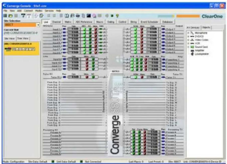
You can switch between modes by clicking on the Mode buttons on the Button Bar. For a description of the Console screen components while in Configuration Mode, see Navigating Converge Console.
Configuration Mode Tabs
Console has ten tabs on the Tab Bar that provide specific configuration options while in Configuration Mode:
Unit
Channel
Matrix
AEC Reference/PA Adapt Reference Tab
Macro
Gating
Control
String
Event Scheduler
Database
These tabs are described in the following sections.
UNIT TAB
The Unit Tab shows a detailed block diagram for the unit selected in the site pane. The diagram shows the path of the audio signal based on the current unit configuration, and provides a graphical explanation of each stage of audio processing.
Accessing the Unit Tab
Console automatically starts in Configuration Mode. When you load a site file, Console displays the Unit tab by default as shown below. To switch to the Unit tab from any other tab, click the Unit tab on the Tab Bar.
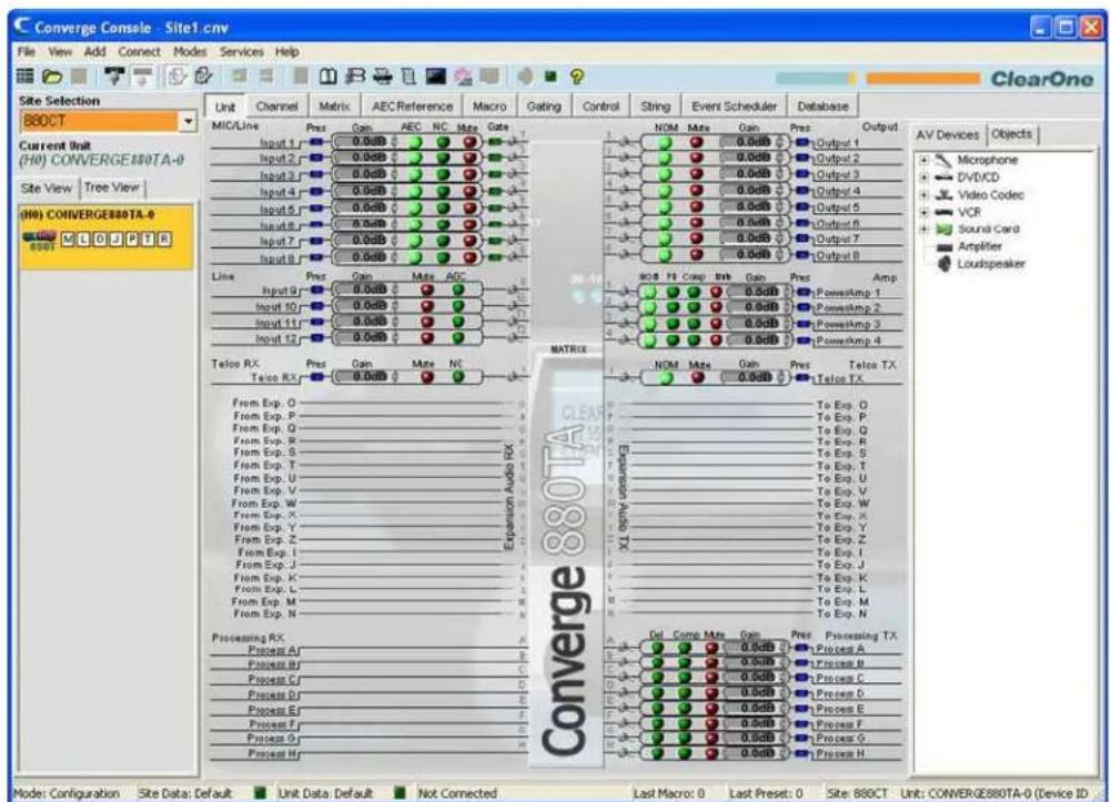
NOTE: The Unit tab shown above is for an 880AT with the Tree View tab selected in the Site Pane. All units that are connected and belong to the site also appear in the Tree View tab. The Unit tab display for other Converge/Converge Pro unit types will vary from that shown, depending on the number of inputs, outputs, telco connections, etc. for the model selected.
Unit Tab Functionality
The graphical elements shown in the block diagram of the Unit tab provide shortcuts to the basic configuration settings for each channel type. For full configuration control of a channel, use the Channel tab.
For all channels in the Unit tab display, the blue Pres (Audio Presence) LEDs illuminate to indicate the presence of audio on the channel. For Mic Input Channels, the green Gate LEDs illuminate to indicate that the Mic is gated on.
The following sections describe the configuration setting shortcuts available in the Unit tab.
Input Channel Settings
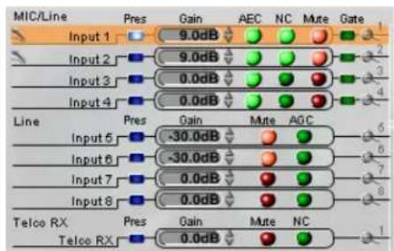
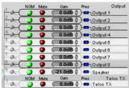
Pointing to an input channel on the left side of the screen highlights it in orange, and shows the routing for the channel in white on the right side of the screen (shown above). Clicking the channel selects it and displays the routing to other units in the site by channel type in the site pane (shown below).
Set the desired Gain settings for the Input channel using the Gain Arrows to the right of the Gain Display. Toggle AEC (Acoustic Echo Cancellation), NC (Noise Cancellation), and Mute on and off by clicking the associated LED Buttons.
To access the full set of configuration settings for the channel, click on the Magnifying Glass icon located next to the channel.
Output Channel Settings
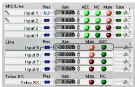
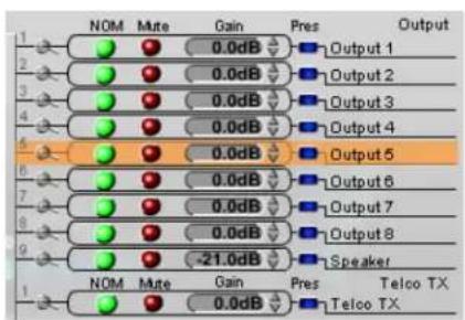
Pointing to an output channel on the right side of the screen highlights it in orange, and shows the routing for the channel in white on the left side of the screen (shown above). Clicking the channel selects it and displays the routing to other units in the site by channel type in the Site Pane (shown below).
Set the desired Gain settings for the output channel using the Gain Arrows to the right of the Gain Display. Toggle NOM (Number of Open Mics/Constant Level), and Mute on and off by clicking the associated LED Buttons.
To access the full set of configuration settings for the channel, click on the Magnifying Glass icon located next to the channel.
Processing Channel Settings
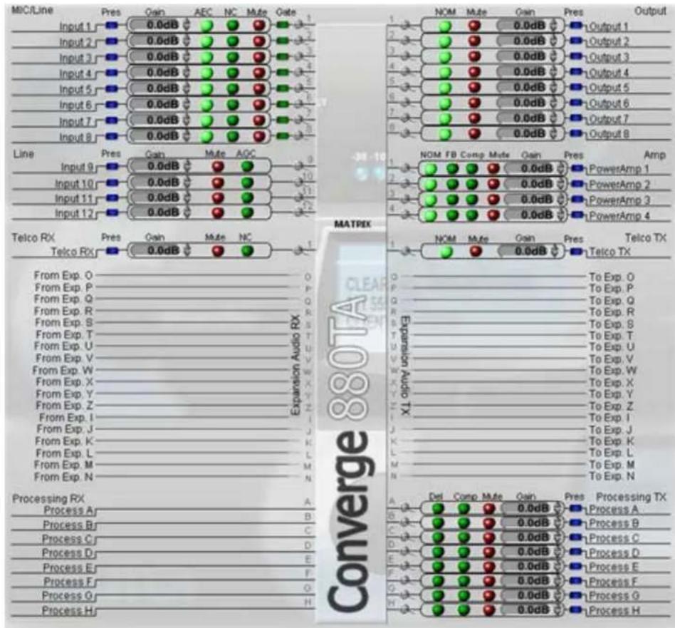
Pointing to a processing channel in the Matrix section of the screen highlights it in orange, and shows the routing for the channel in white (shown above). Clicking the channel selects it and displays the routing to other units in the site by channel type in the Site Pane (shown below).
Set the desired Gain settings for the processing channel using the Gain Arrows to the right of the Gain Display. Toggle Del (Delay), Comp (Compression), and Mute on and off by clicking the associated LED Buttons.
To access the full set of configuration settings for the channel, click on the Magnifying Glass icon located next to the channel.
Fader Channel Settings
NOTE: The Converge Pro 880TA and Converge SR 1212A do not have fader settings.
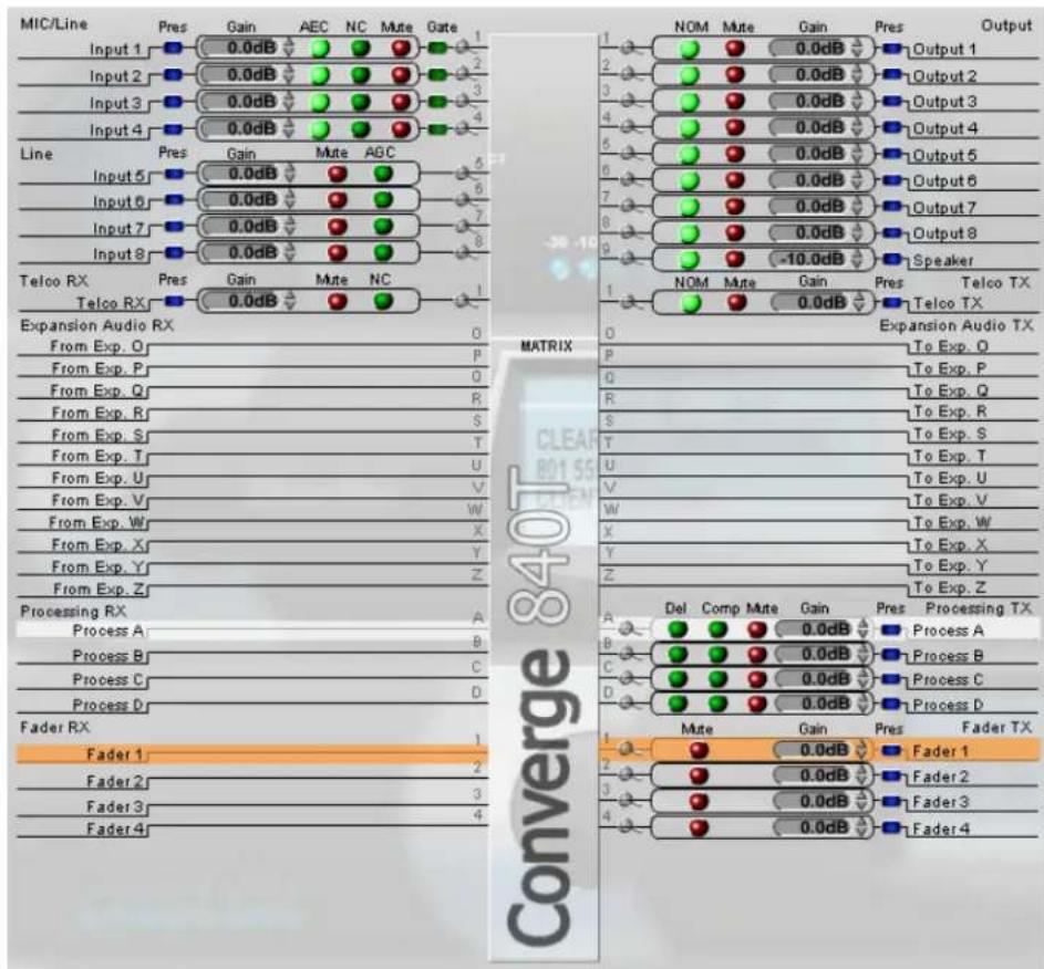
Pointing to a fader channel in the Matrix section of the screen highlights it in orange, and shows the routing for the channel in white (shown above). Clicking the channel selects it and displays the routing to other units in the site by channel type in the Site Pane (shown below).
Set the desired gain settings for the fader channel using the Gain Arrows to the right of the Gain Display. Toggle mute on and off by clicking the associated Mute LED Button.
To access the full set of configuration settings for the channel, click on the Magnifying Glass icon located next to the channel.
Expansion Audio RX and TX
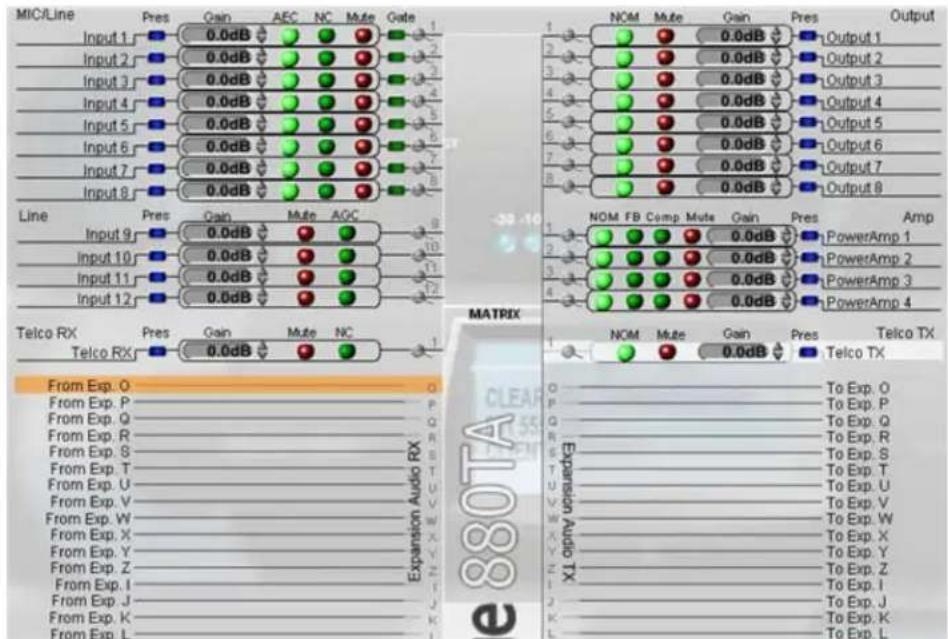
Pointing to an Expansion RX or Expansion TX channel in the Matrix section of the screen highlights it in orange. Clicking the channel selects it and shows the Input (TX channels only), Output (RX channels only), Processing, Expansion, and Fader channel routing (white highlights) for the selected channel as shown above.
Power Amp Channels (Converge Pro 880TA and SR 1212A)
The Converge Pro 880TA and SR 1212A units are equipped with four 35 watt amplifiers capable of running in either 8 ohm or 70/100 volt modes. Each amplifier operates independently to provide maximum flexibility.
Click the Channel Tab and refer to the Matrix Row. The four Power Amp channels are listed after the Outputs -- click any of the Power Amp channels to access the available options.
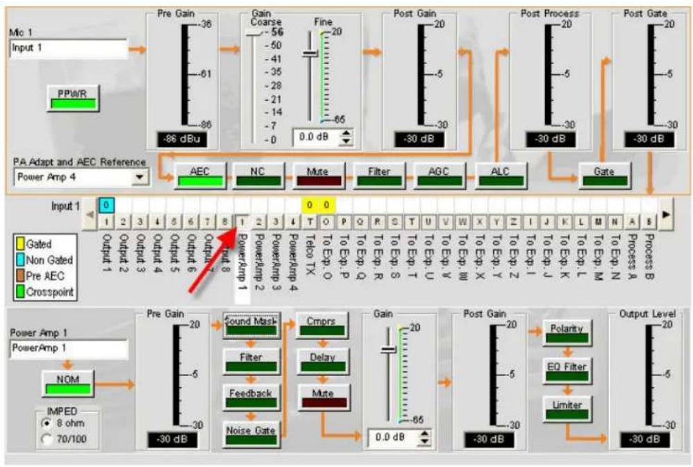
flowchart
graph TD
    A["Input 1: Mic 1"] --> B["PPWR"]
    B --> C["Pre Gain: -86 dBu"]
    C --> D["Gain Coarse: -56 dB"]
    D --> E["Fine: -20 dB"]
    E --> F["Post Gain: -30 dB"]
    F --> G["Post Process: -30 dB"]
    G --> H["Post Gate: -30 dB"]

    subgraph Input 1
        I["0 Output 1"] --> J["1 2 3 4 5 6 7 8"]
        J --> K["Output 2 Output 3 Output 4 Output 5 Output 6 Output 7 Output 8"]
        K --> L["Output 8"]
        M["0 Power Amp 1"] --> N["NOM"]
        O["0 Power Amp 1"] --> P["IMPED 8 ohm 70/100"]
    end

    subgraph Gated
        Q["Gated"] --> R["Non Gated"]
        S["Pre AEC"] --> T["Crosspoint"]
    end

    subgraph Pre AEC
        U["PowerAmp 1"] --> V["Noise Gate"]
        W["PowerAmp 2"] --> X["Filter"]
        Y["PowerAmp 3"] --> Z["Feedback"]
        AA["PowerAmp 4"] --> AB["Mute"]
        AC["PowerAmp 5"] --> AD["PowerAmp 6"]
        AE["PowerAmp 7"] --> AF["PowerAmp 8"]
        AG["PowerAmp 9"] --> AH["PowerAmp 10"]
        AI["PowerAmp 11"] --> AJ["PowerAmp 12"]
        AK["PowerAmp 13"] --> AL["PowerAmp 14"]
        AM["PowerAmp 15"] --> AN["PowerAmp 16"]
        AO["PowerAmp 17"] --> AP["PowerAmp 18"]
        AQ["PowerAmp 19"] --> AR["PowerAmp 20"]
        AS["PowerAmp 21"] --> AT["PowerAmp 22"]
        AU["PowerAmp 23"] --> AV["PowerAmp 24"]
        AW["PowerAmp 25"] --> AX["PowerAmp 26"]
        AY["PowerAmp 27"] --> AZ["PowerAmp 28"]
        BA["PowerAmp 29"] --> BB["PowerAmp 30"]
        BC["PowerAmp 31"] --> BD["PowerAmp 32"]
        BE["PowerAmp 33"] --> BF["PowerAmp 34"]
        BG["PowerAmp 35"] --> BH["PowerAmp 36"]
        BI["PowerAmp 37"] --> BJ["PowerAmp 38"]
        BK["PowerAmp 39"] --> BL["PowerAmp 40"]
        BM["PowerAmp 41"] --> BN["PowerAmp 42"]
        BO["PowerAmp 43"] --> BP["PowerAmp 44"]
        BQ["0.0 dB"] --> BR["-65 dB"]
    end

    subgraph Output Level
        BS["-30 dB"] --> BT["-5 dB"]
        BU["-30 dB"] --> BV["-30 dB"]
    end

    style Input 1 fill:#f9f,stroke:#333
    style Gated fill:#ccf,stroke:#333
    style Pre AEC fill:#cfc,stroke:#333
    style Crosspoint fill:#fcc,stroke:#333
Options for the selected Power Amp appear below the Matrix row.
- IMPED: Selects the Power Amplifier's impedance. Options are 8 ohm and 70/100 volt.
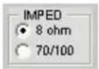
Sound Mask• : Launches the Sound Mask pane.
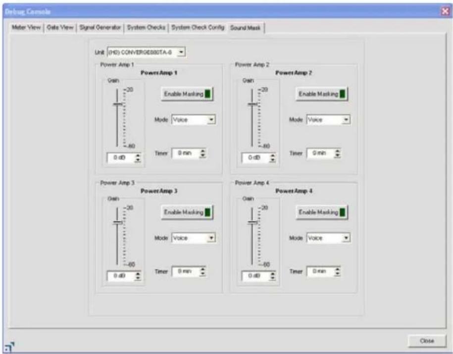
» Sound Masking is an Amplifier Out only feature consisting of three modes:
Off1. : Disables the feature
- Voice: Masking operates only in the range usually used when the target audio is vocal.
- Wideband: Masking operates throughout the audible range of the unit.
- Filter: Filters selected from the Power Amp channel are only applied to the amplifier. Otherwise they operate in any combination consistent with the Processing channel filters.
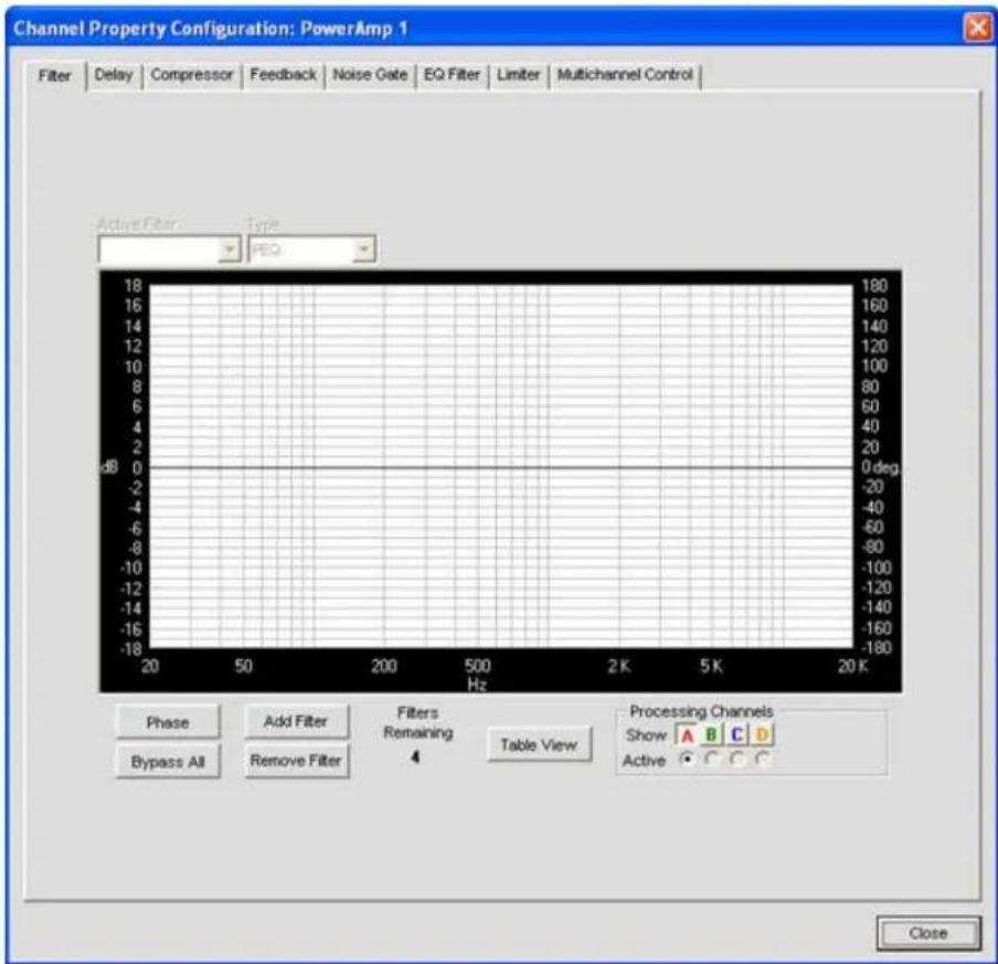
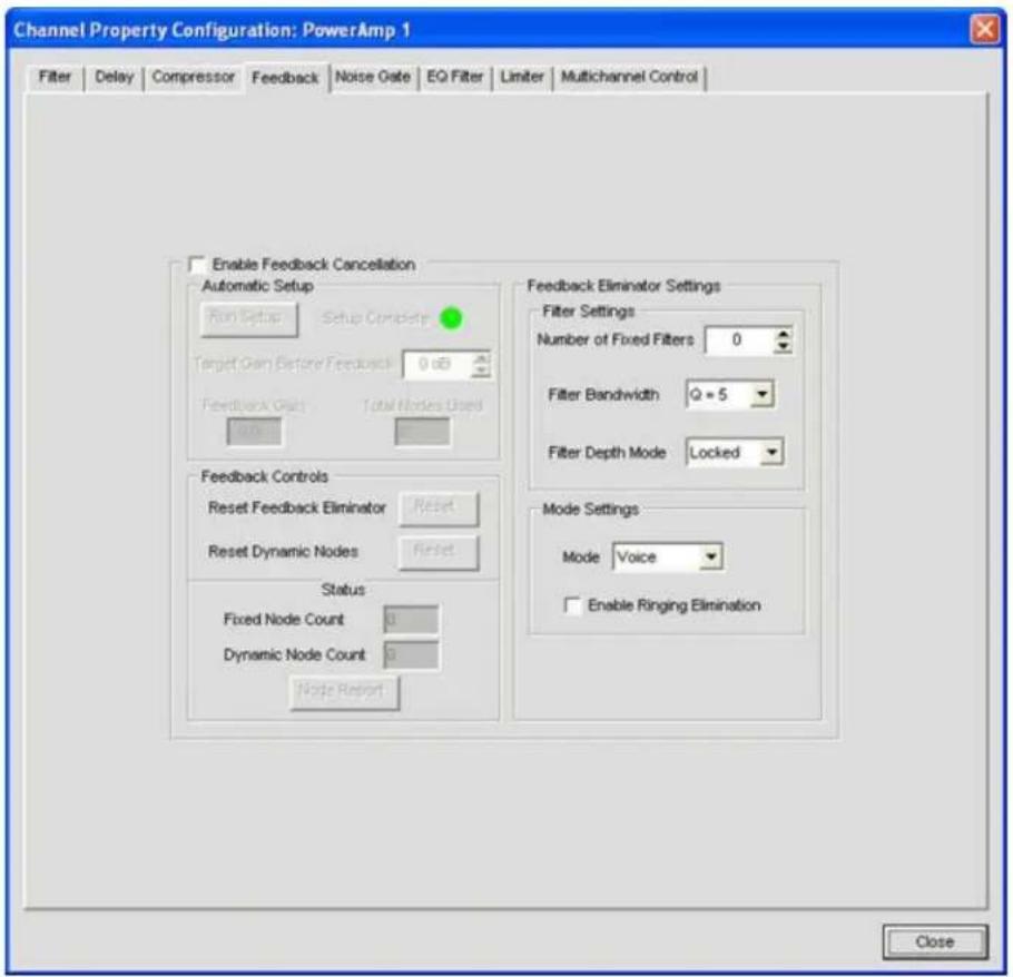
This feature allows you to reduce feedback through a simple configuration window.
Enable Feedback Cancellation1. : Enables or Disables the feature.
- Automatic Setup: Creates notch filters based on your choice of Feedback Cancellation settings.
Target Gain Before Feedback: Set your desired dB rating. The unit slowly increases dB, adding notch filters at detected feedback frequencies until it either reaches the target level or reaches the number of Fixed Filters (specified in the Filter Settings - Number of Fixed Filters). The system detects feedback through an open mic while levels are increased. If the target is reached without using the specified number of fixed filters, the remaining "slots" are used as Dynamic Filters to be applied as the environment changes.
Feedback Controls »:
- Reset Feedback Eliminator: Clicking Reset clears all settings related to this feature.
- Reset Dynamic Nodes: Clicking Reset only clears dynamic filters; Fixed Filters remain in place.
» Status: Reports the number of Fixed and Dynamic nodes. A total of 16 nodes can be used, regardless of type.
- Node Report: Creates a text report listing existing node details.
» Feedback Eliminator Settings:
- Filter Settings: Filters are applied according to the specifications the user sets.
» Number of Fixed Filters: Up to 16 Fixed Filters are applied. If the specified number of filters are not required, they become Dynamic Filters.
» Filter Bandwidth: Bandwidth is determined by the specified Q factor. A lower Q creates a filter that works across a wider frequency range. A higher Q utilizes a narrower range.
Filter Depth Mode »:
- Locked re-uses filters. A replacement filter, with new settings and increased filter depth is applied in place of an existing filter.
Unlocked adds a new filter at a specific frequency. No filters are replaced, so this setting will count against the total number of filters available.
» Mode Settings: Voice and Music presets are available to fine-tune the feedback eliminator.
NOTE: Voice Mode is the more aggressive setting.
» Enable Ringing Elimination: Allows the Feedback Cancellation to attempt to suppress ringing.
NOTE: This setting adjusts slowly to eliminate ringing.
- Click Close to close the window once the Setup Complete indicator has switched from yellow (in process) to green (setup complete).
- Noise Gate: This feature reduces buzz and hum from the amp when the system is on but not in use.
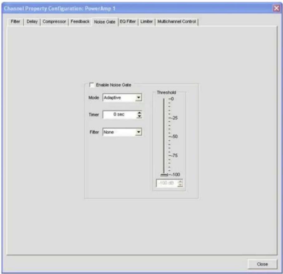
Enable Noise Gate1. : Enables or Disables the feature.
Mode »:
- Adaptive: Actively monitors the noise floor of the environment and determines when to enable gating.
Manual• : User sets Threshold.
» Timer: Time before the Amp begins gating.
NOTE: The Noise Floor must be at the Threshold Level for the duration set in the Timer in order to enable the Noise Gate.
Filter »:
None• : No filtering is applied to noise.
• High Pass: A High Pass filter is applied to noise before threshold reading.
- Low Pass: A Low Pass filter is applied to suppress noise before threshold reading.
- High/Low Pass: High and Low Pass filtering is applied to noise before threshold reading.
- Compressor: Allows the user to enable compression on an amp channel based on configurable parameters. With a few exceptions (noted below) this feature operates identically to the Processing Compressors.
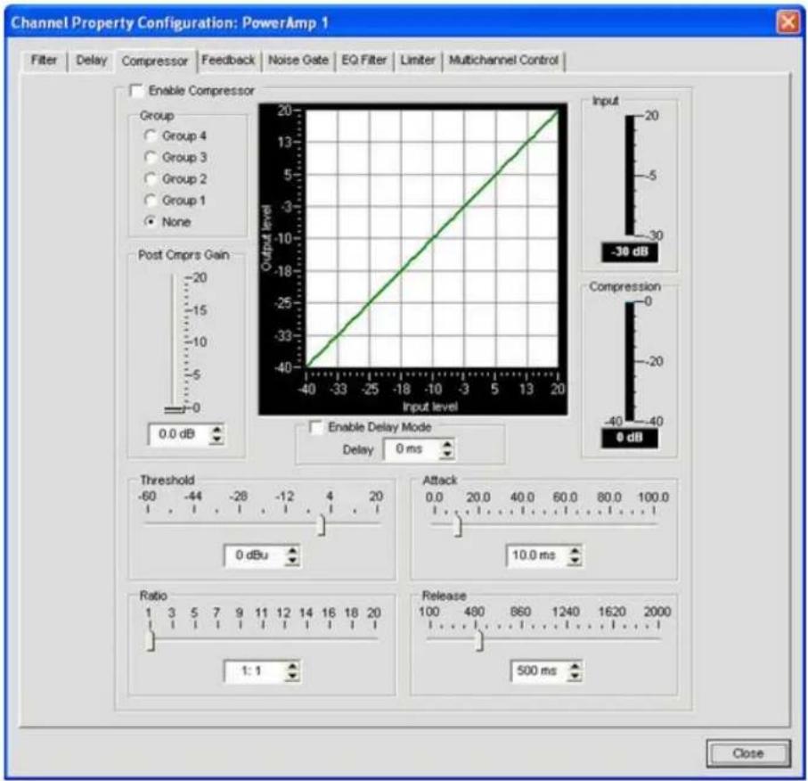
» Delay Mode: Enabling Delay Mode sets a timed delay after which the Compressor activates. Timing
ranges from 0 to 20ms.
Note: Groups do not interact with Processor channels.
Mute• : Mutes the specific Power Amp channel.
Polarity• : Reverses the amplifier's output polarity.
- EQ Filter: Adjusts specific frequency bands within a +/-12db range.
» Enable EQ Filter: Enables or disables the EQ.
Limiter• : Establishes a ceiling level for the amplifier output.
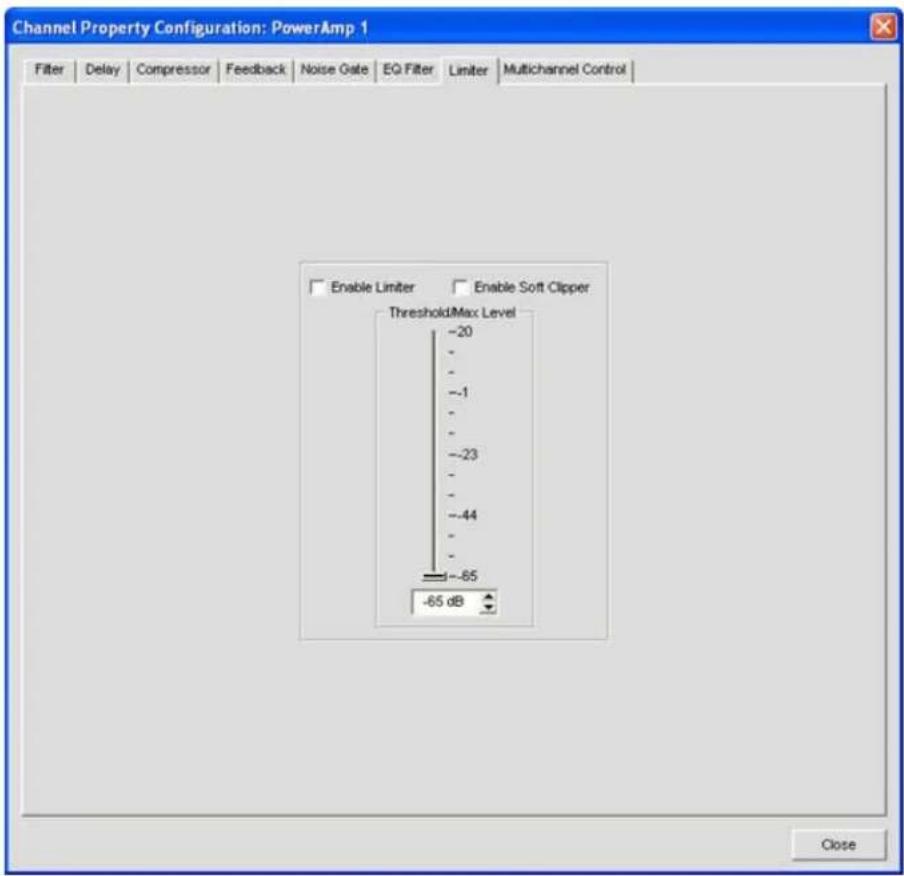
» Enable Limiter: Limits the output to the Threshold/Max Level specified by the user.
» Enable Soft Clipper: Softens the clipping effect at Threshold/Max level to prevent damage to external equipment.
Note: Both settings can be active simultaneously.
- Multichannel Control: Multichannel Control is only available on amplifier channels. Each of the 4 amplifiers can be assigned to one of two Multichannel groups. When amplifier channels are assigned to a Multichannel group, Mute and Gain for the group are controlled from a single point.
NOTE: Mutiple PA Channel Selections cannot be applied to both groups simultaneously. If you assign PA 1 and 3 to Multichannel Group1, those amplifiers cannot be assigned to Multichannel Group 2 without removing them from the first group.
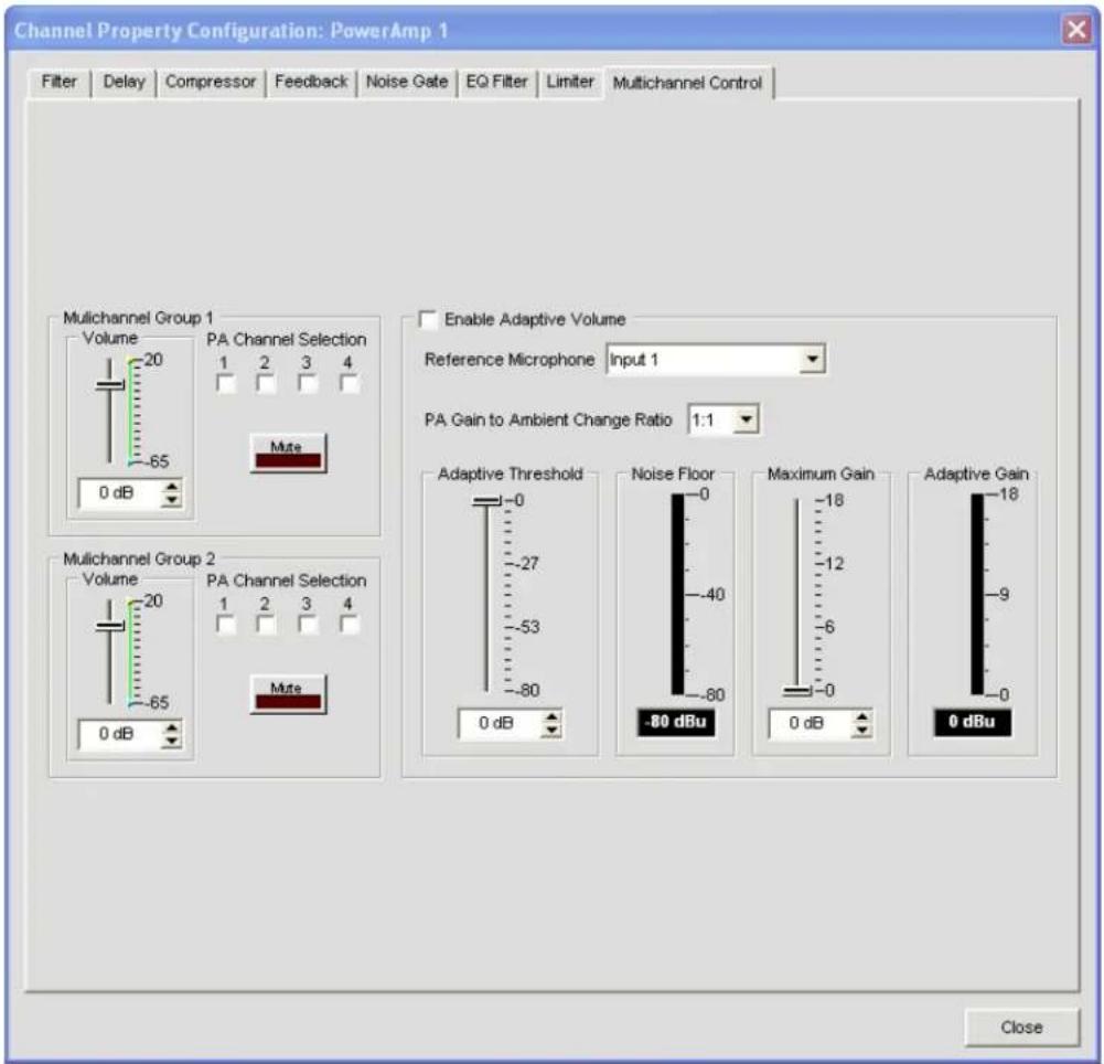
• Volume: Indicates the volume level assigned to the Multichannel Group
- PA Channel Selection: Each box represents a PA Channel. Check the box you wish to assign to the corresponding Multichannel Group.
Mute• : Mutes the Multichannel Group
- Enable Adaptive Volume: When enabled the level of the PA Channel will adjust based on the Noise Floor "heard" by the selected reference microphone. As the level of noise changes, the output level adjusts according to the selected PA Gain to Ambient Change Ratio. For example, if the rate is set to 2:1 the amplifier level will adjust by 2 dB for every 1 dB in noise for increase. The gain applied is governed by the Maximum Gain setting. Before any gain is applied the noise floor heard by the mic must be equal to or greater than the Adaptive Gain setting.
For more information, refer to the Table of Contents for these related topics:
AEC (Auto Echo Cancellation)
NC (Noise Cancellation)
Configuration Mode
- Channel Tab
- Matrix Tab
- Processing Settings
- Fader Settings
CHANNEL TAB OVERVIEW
The Channel section of Console makes the full set configuration controls available for a given channel, from input to processing to output. The type of channel selected in the Tree View tab of the Current Unit pane determines the contents of the Channel pane in the center of Console.
The channels available in the Tree View tab are:
Mic Input Channels Line Input Channels Telco/VoIP rx Channel Output Channels Telco/VoIP tx Channel Processing Channels Fader Channels
Accessing Channel Tab
Selecting a channel in the Tree View tab displays the Channel Tab for that channel. For example, the channel tab for a mic channel is shown below:
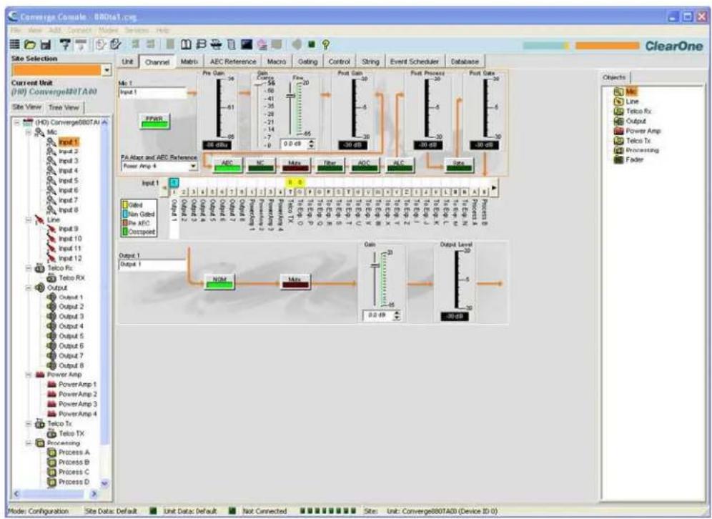
Channel Configuration Controls
As shown above, the configuration settings for a channel are displayed as controls (buttons, sliders, check-boxes, selection lists, text entry boxes) in the Channel pane. Use the text entry boxes to assign custom names. Use the drop-down lists to select from a list of configuration values. Use the sliders to set a discrete value for channel configuration parameters.

Some buttons, such as the PPWR (Phantom Power) button shown above, toggle features on and off.

flowchart
graph LR
    A["AEC"] --> B["NC"]
    B --> C["Mute"]
    C --> D["Filter"]
    D --> E["AGC"]
    E --> F["ALC"]
    F --> G["Gate"]
Other buttons, including AEC (Acoustic Echo Cancellation), NC (Noise Cancellation), Filter, AGC (Automatic Gain Control), ALC (Automatic Level Control), shown above, bring up the Channel Property Configuration screen shown below.
Channel Property Configuration Screen
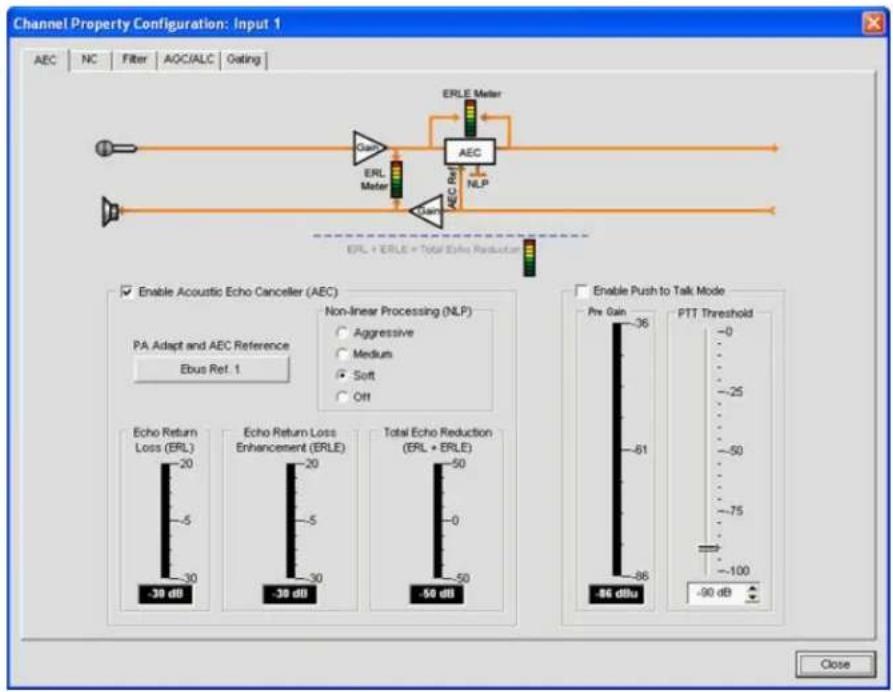
The Channel Property Configuration screen is used to configure Mic Input, Line Input, and Processing channels. The tabs available in this screen change depending on the type of channel selected in the Tree View pane of Console.
Meters
In addition to the configuration controls available in the Channel pane, there are meters showing signal levels in real time at each stage of signal processing. The meters shown change with the type of channel selected. For example, the meters for Mic Input channels are shown below:
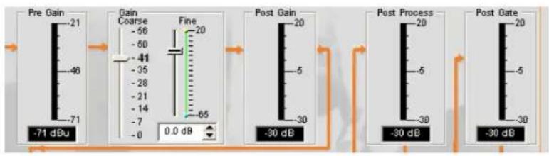
NOTE: All meters in Console are peak-level meters.
Channel Routing Matrix
The channel routing matrix of the Channel pane shows the associated Matrix row and routing configuration for the channel selected in the Tree View tab of the Current Unit pane. The channel routing matrix of the Channel pane for a Mic Input channel is shown below.

Use the routing legend to determine the current cross-point configuration of the selected input channel. As shown in the example above, Input 1 is non-gated and cross pointed by default to Output 1. It is also gated and cross pointed by default to Outputs 5-7, Telco/VolP tx, and Exp Bus O.
Clicking a cross point box selects it, clicking it a second time sets the cross point, as indicated by a colored box. The dB level for set cross points is shown numerically in the box. To adjust cross point gain/attenuation, right-click on a cross point box and select Cross Point from the shortcut menu as shown below.
The Cross Point Attenuation slider appears as shown below. Move the slider or use the selector box to set the gain/attenuation level in dB. The range is from -60 to +12dB in .5dB increments. The default is 0dB.
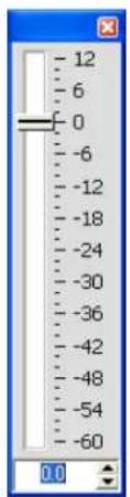
NOTE: Changes are automatically saved when you close the slider.

In the channel routing matrix section of the Channel pane, pressing the channel button underneath an Output, Process, or Fader cross point box (shown above) displays the signal flow diagram and configuration controls for that channel (shown below).

flowchart
graph LR
    A["Input 1"] --> B["Output 1"]
    B --> C["NOM"]
    C --> D["Mate"]
    D --> E["Gain"]
    E --> F["Output Level -30 dB"]
    style A fill:#f9f,stroke:#333
    style B fill:#ccf,stroke:#333
    style C fill:#cfc,stroke:#333
    style D fill:#fcc,stroke:#333
    style E fill:#ffc,stroke:#333
    style F fill:#fcc,stroke:#333
This display is identical to that shown on the Channel Tab when the channel is selected in the Tree View pane.
NOTE: Changes to channel configuration settings made in the channel routing matrix apply globally to the channel. For example, changing the label (name) from "Output 1" to "Ceiling Speakers" changes the name of the output channel in the Tree View pane, and everywhere else the label appears in Console.
For additional information, refer to the Table of Contents for these related topics:
Mic Input Channels•
Line Input Channels•
Telco/VoIP rx Channel •
Output Channels•
Telco/VoIP tx Channel •
Processing Channels•
Fader Channels•
AEC (Acoustic Echo Cancellation) •
NC (Noise Cancellation), Filter•
AGC (Automatic Gain Control)
ALC (Automatic Level Control) •
- Mic Gating
- Filters
- Site Pane
- Objects Pane
AEC (ACOUSTIC ECHO CANCELLATION)
AEC (Acoustic Echo Cancellation) reduces or removes acoustical echo from an input signal, thereby improving audio clarity. Converge Pro devices perform AEC using the full bandwidth (20hz to 22kHz) of the signal.
AEC uses a reference source to perform AEC based on the acoustic characteristics and dynamics of a specific room. Use the AEC Reference/PA Adapt Reference tab to set up these references.
Accessing AEC
With the Channel tab selected on the Tab Bar, select the desired Mic Input channel on the Tree View tab in the Site Pane, and press the AEC button (located just below the Pre Gain meter).
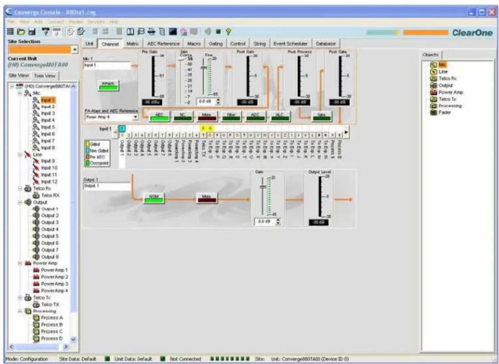
The Channel Property Configuration screen appears with the AEC tab selected (see below).
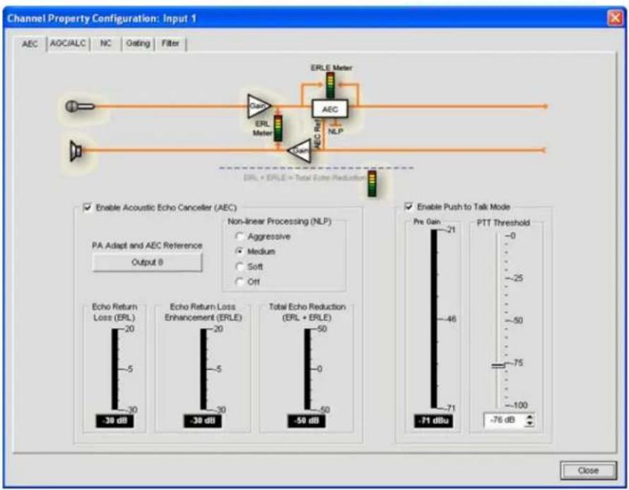
The AEC tab shows a signal flow diagram for AEC, and has the following features: Enable AEC, PA Adapt and AEC Reference, NLP (Non-linear Processing), and PTT (Push-to-Talk) mode. These features are described in the following sections.
Enable AEC Checkbox
Select the checkbox to enable AEC.
PA Adapt and AEC Reference Button
This button displays the expansion bus output channel currently used as the AEC reference for the selected channel. Clicking the button closes the Channel Property Configuration window and opens the AEC Reference tab in the center pane of Console.
NLP (Non-Linear Processing) Radio Buttons
NLP increases the power of echo cancellation for difficult acoustical environments. NLP features four settings: Soft, Medium, Aggressive, Off. The default is soft.
NOTE: Use NLP with care. There are corresponding trade-offs associated with NLP, including suppression and half-duplex operation.
The AEC tab also includes meters for Echo Return Loss (ERL), Echo Return Loss Enhancement (ERLE), and Total Echo Reduction (ERL + ERLE).
ERL (Echo Return Loss) Meter
Shows the coupling between the reference signal and the input to the echo canceller—the difference of the two levels. This is an average meter that updates when a receive-only signal is present.
ERLE (Echo Return Loss Enhancement) Meter
Shows the loss through the echo cancellation and non-linear processing chain—the difference of the two levels. This is an average meter that updates when a receive-only signal is present.
ERL + ERLE Meter
Shows the total ERL and ERLE reduction. This is an average meter that updates only when a receive -only signal is present.
PTT (Push to Talk) Mode
Select the Enable Push to Talk Mode checkbox to enable PTT. PTT notifies AEC when a microphone is switched off, and freezes AEC convergence until the microphone is switched back on. As a result, PTT helps prevent AEC divergence and improves overall AEC performance with push to talk microphones.
When the microphone is off, set the PTT Threshold slider to the level of the Pre-Gain Meter for the channel.
For additional information, refer to the Table of Contents for these related topics:
AEC Reference/PA Adapt Reference Tab
AGC/ALC (Automatic Gain Control/Automatic Level Control)
NC (Noise Cancellation) •
Mic Gating•
Filters•
Line Input Settings•
Mic Input Settings •
NC (NOISE CANCELLATION)
NC (Noise Cancellation) is a process in which ambient (background) noise is removed from an input signal, with no noticeable degradation in signal quality. NC is available on Mic Input (excluding SR 1212 and SR 1212A) and Telco/VolP rx channels.
Accessing NC
With the Channel tab selected in the Center Pane, select the desired Mic Input channel on the Tree View tab in the Site Pane, and press the NC button (located just below the Coarse Gain slider).
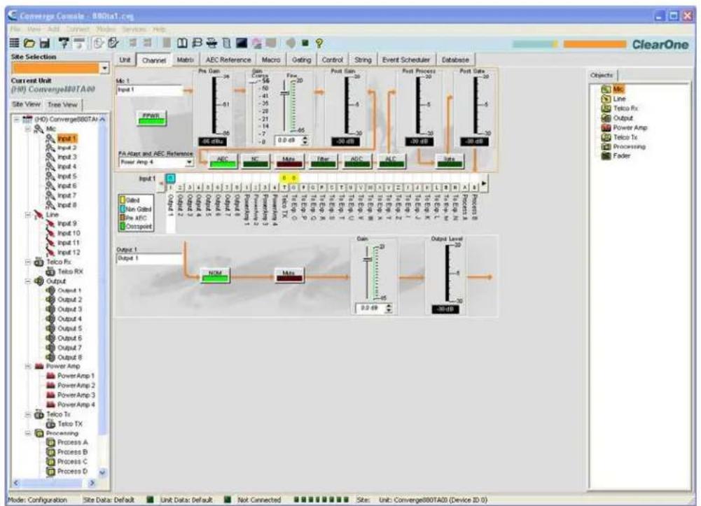
The Channel Property Configuration screen appears with the NC tab selected as shown below.
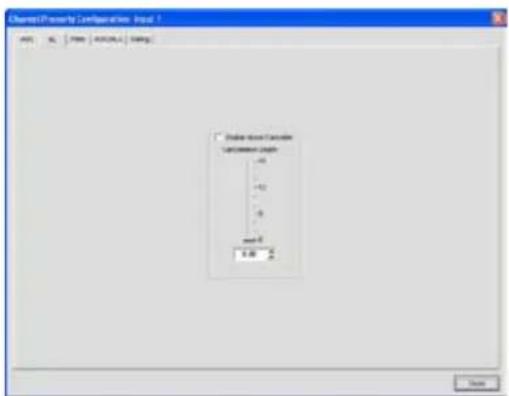
Configuring Noise Cancellation
Select the Enable Noise Canceller checkbox to enable NC for the channel. Adjust the Cancellation Depth slider to the dB setting which provides the best combination of low noise and maximum speech clarity. The cancellation depth can also be set using the arrow buttons or by entering a value directly in the field. The attenuation depth can be set in 1dB increments from 6dB to 15dB. The default is 6dB. The default NC is Off.
For additional information, refer to the Table of Contents for these related topics:
Channel Tab Overview•
AEC (Acoustic Echo Cancellation)
AGC/ALC (Automatic Gain Control/Automatic Level Control)
Mic Gating•
Filters•
Mic Input Settings•
Telco/VoIP Rx Settings (TH20, VH20, 840T, 880, 880T, 880TA)
FILTERS
Filters enable you to shape the audio signals from Mic Input channels for improved audio quality.
There are four configurable filter types available:
All Pass•
High Pass•
Low Pass•
Notch·
PEQ (Parametric Equalizer)
Accessing Filters
With the Channel tab selected on the Tab Bar, select the desired input channel on the Tree View tab in the Site Pane, and press the Filter button (located just below the Post Gain meter).
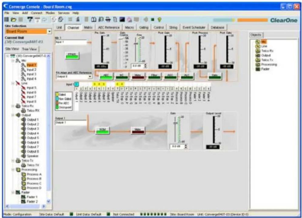
flowchart
Converge Console interface showing ADC and Pre-Dam/Pre-ADC comparison and output generation flowThe Channel Property Configuration screen appears with the Filter tab selected as shown below.
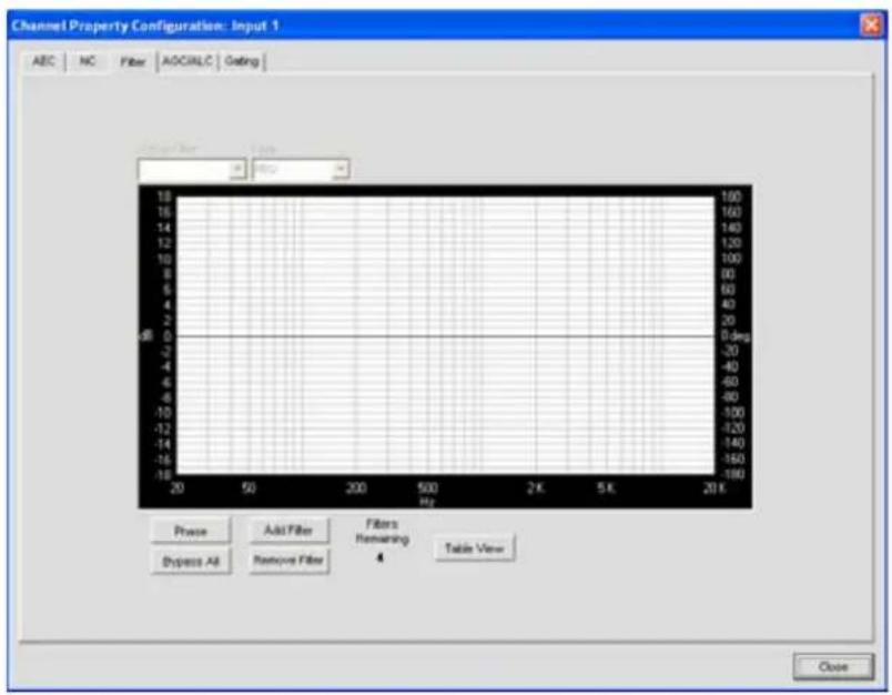
The following sections describe how to configure and activate input channel filters.
Active Filter
Use the Active Filter drop-down list to select among active filters. Selecting a filter highlights its node on the graph and displays its current settings. You can configure up to four active filters per input channel.
NOTE: There are no filters configured by default. Press the Add Filter button to create a filter for the input channel. When you add a filter, it appears in the Active Filter drop-down list, and on the active filter graph.
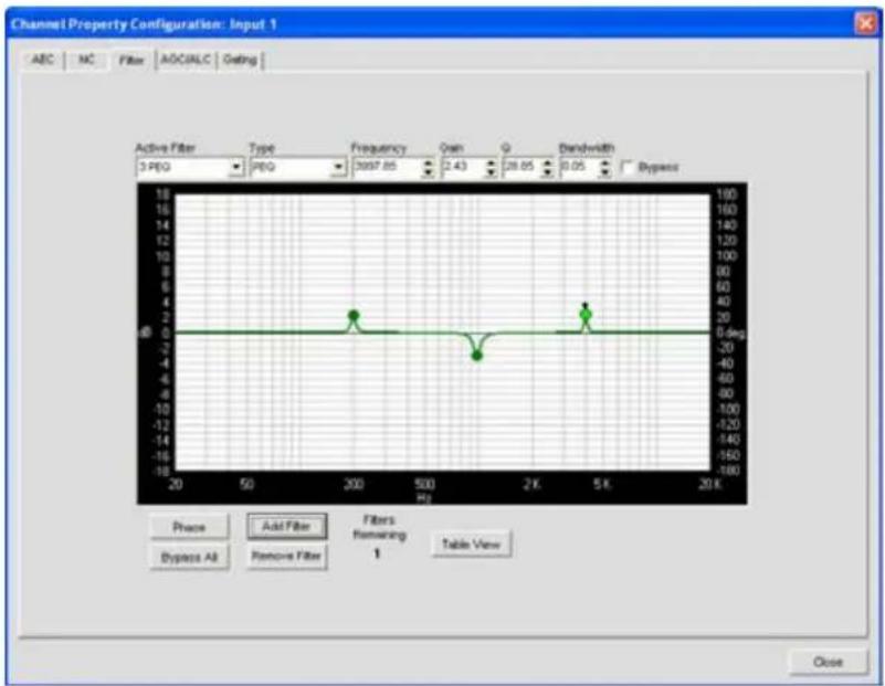
line
| Frequency (Hz) | Amplitude (deg) | | -------------- | --------------- | | 3097.65 | 40 | | 28.65 | 20 | | 28.65 | -20 |In graph view, you can click on a filter node and drag it to the desired location on the graph. The setting fields immediately reflect changes made by dragging filter nodes.
Filter Nodes
In graph view, you can click on a filter node and drag it to the desired location on the graph. The setting fields immediately reflect changes made by dragging filter nodes.
Filter node colors represent the following:
- Green: The filter node is selected and active. Dragging a green node changes the gain setting for PEQ filters and the frequency for all filter types.
Grey• : The filter node is selected but not active.
White• : The filter node is not selected and not active.
- Black: Dragging a black filter node changes bandwidth settings for Notch and PEQ filter types.
Adding Filters
To add additional filters, click the Add Filter button. The number of remaining available filters for the channel is shown under Filters Remaining.
Filter Types
Use the Type drop-down list to select from the following input filters:
- All Pass. Frequency range is 20.00Hz to 20.00kHz. All pass changes the phase of the audio signal at the set frequency.
- High Pass. Selectable frequency cutoff is 20.00Hz to 20.00kHz. Rolloff is 12dB/octave. Level is fixed at 0dB.
- Low Pass. Selectable frequency cutoff is 20.00Hz to 20.00kHz. Rolloff is 12dB/octave. Level is fixed at 0dB.
- Notch. Center frequency range is 20.00Hz to 20.00kHz. Bandwidth is from .05 to 5.00 octaves in .01 octave increments. Level is fixed at -80dB.
- PEQ (Parametric Equalizer). Center frequency range is 20Hz to 20kHz in .01Hz increments. Bandwidth is .05 to 5 octaves in .01 octave increments. Level range is -15 to +15dB in 0.5dB increments.
Frequency (Available for all filter types)
Use the Frequency selector box to set the center frequency (in Hertz) for the filter you are configuring. Range is from 20Hz to 20kHz in 1Hz increments. The default is 1kHz.
Gain (Available for PEQ filters only)
Use the Gain selector box to set the gain value for the filter you are configuring. Range is from -15 to 15dB. The default is 0dB.
Q (Available for Notch and PEQ filters only)
Use the Q (Quality Factor) selector box to select the ratio of the center frequency divided by the bandwidth. Q is the inverse of bandwidth, and the two parameters are linked. Therefore changing the Q value also changes the bandwidth value. Range is from .18 to 28.85.
Bandwidth (Available for Notch and PEQ filters only)
Use the Bandwidth selector box to set the difference between the upper and lower points of a filter's audio passband. Bandwidth is the inverse of Q, and the two parameters are linked. Hence changing the bandwidth value also changes the Q value. The range is .05 to 5.00 octaves.
Bypass (Available for all filter types)
Use the Bypass checkbox to bypass the currently selected active filter. This feature allows you to configure different filters and save them for future use without having to recreate them.
Phase
Press the Phase button to display the phase relationship of the graphed frequency response (appears as a grey line on the active filter graph). The phase scale appears on the right vertical axis of the graph.
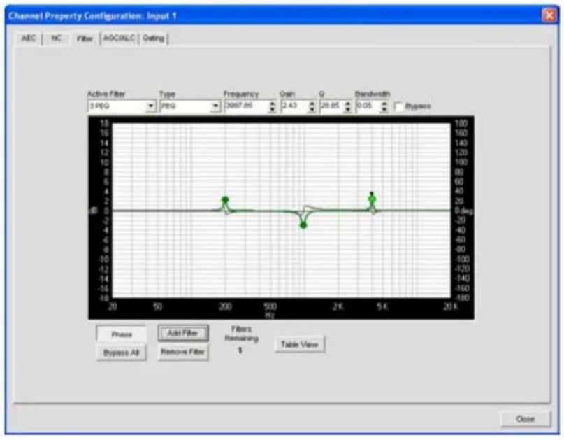
line
| Frequency (Hz) | Gain (deg) | | -------------- | ---------- | | 200 | 0 | | 1500 | -4 | | 5000 | 0 |Bypass All
Press the Bypass All button to bypass all filters for the selected input channel. The filters are grayed out in graph view, and the bypass status is shown as on in table view.
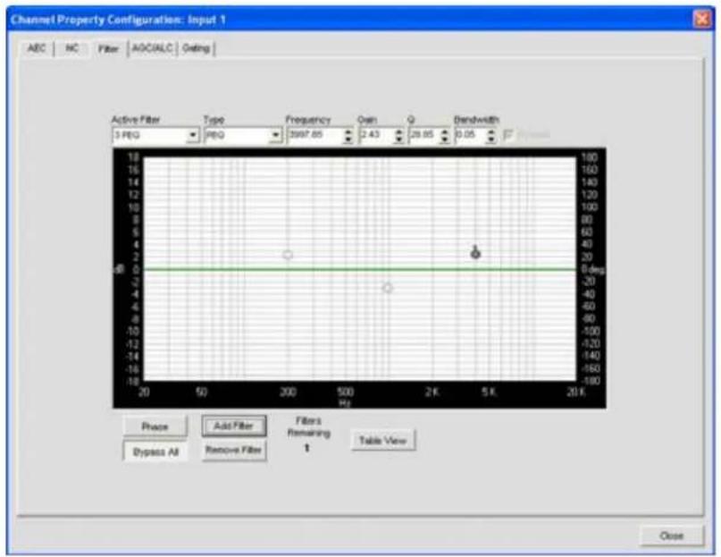
line
Channel Property Configuration: Input 1 | Frequency (Hz) | Value | | :--- | :--- | | 300 | 2.43 | | 500 | 29.85 | | 2K | 0.05 | | 5K | 0.05 | | 20K | 0.05 | | 20 | 0 deg | | 18 | 0 deg | | 16 | 0 deg | | 14 | 0 deg | | 12 | 0 deg | | 10 | 0 deg | | 8 | 0 deg | | 6 | 0 deg | | 4 | 0 deg | | 2 | 0 deg | | 0 | 0 deg | | -2 | 0 deg | | -4 | 0 deg | | -6 | 0 deg | | -8 | 0 deg | | -10 | 0 deg | | -12 | 0 deg | | -14 | 0 deg | | -16 | 0 deg | | -18 | 0 deg | | -20 | 0 deg | | -22 | 0 deg | | -24 | 0 deg | | -26 | 0 deg | | -28 | 0 deg | | -30 | 0 deg | | -32 | 0 deg | | -34 | 0 deg | | -36 | 0 deg | | -38 | 0 deg | | -40 | 0 deg | | -42 | 0 deg | | -44 | 0 deg | | -46 | 0 deg | | -48 | 0 deg | | -50 | 0 deg | | -52 | 0 deg | | -54 | 0 deg | | -56 | 0 deg | | -58 | 0 deg | | -60 | 0 deg | | -62 | 0 deg | | -64 | 0 deg | | -66 | 0 deg | | -68 | 0 deg | | -70 | 0 deg | | -72 | 0 deg | | -74 | 0 deg | | -76 | 0 deg | | -78 | 0 deg | | -80 | 0 deg | | -82 | 0 deg | | -84 | 0 deg | | -86 | 0 deg | | -88 | 0 deg | | -90 | 0 deg | | -92 | 0 deg | | -94 | 0 deg | | -96 | 0 deg | | -98 | 0 deg | | -100 | 0 deg | | -102 | 0 deg | | -104 | 0 deg | | -106 | 0 deg | | -108 | 0 deg | | -110 | 0 deg | | -112 | 0 deg | | -114 | 0 deg | | -116 | 0 deg | | -118 | 0 deg | | -120 | 0 deg | | -122 | 0 deg | | -124 | 0 deg | | -126 | 0 deg | | -128 | 0 deg | | -130 | 0 deg | | -132 | 0 deg | | -134 | 0 deg | | -136 | 0 deg | | -138 | 0 deg | | -140 | 0 deg | | -142 | 0 deg | | -144 | 0 deg | | -146 | 0 deg | | -148 | 0 deg | | -150 | 0 deg | | -152 | 0 deg | | -154 | 0 deg | | -156 | 0 deg | | -158 | 0 deg | | -160 | 0 deg | | -162 | 0 deg | | -164 | 0 deg | | -166 | 0 deg | | -168 | 0 deg | | -170 | 0 deg | | -172 | 0 deg | | -174 | 0 deg | | -176 | 0 deg | | -178 | 0 deg | | -180 | 0 deg | | | ... | ...Add Filter
Press the Add Filter button to create a filter for the input channel. When you add a filter, it appears in the Active Filter drop-down list, and on the active filter graph. You can configure up to four active filters per input channel. The number of remaining available filters for the channel is shown under Filters Remaining.
Remove Filter
Press the Remove Filter button to remove the filter currently selected in the Active Filter drop-down list. Removing a filter increments the Filters Remaining by one.
Table View
Press the Table View button to toggle the display between graph view and table view. Table view displays filter settings in table format for all filters configured for the input channel. Clicking on a row in table view selects the filter, displays the current settings for that filter, and allows you to edit the values in the setting fields. Changes made in the setting fields are immediately reflected in the table.
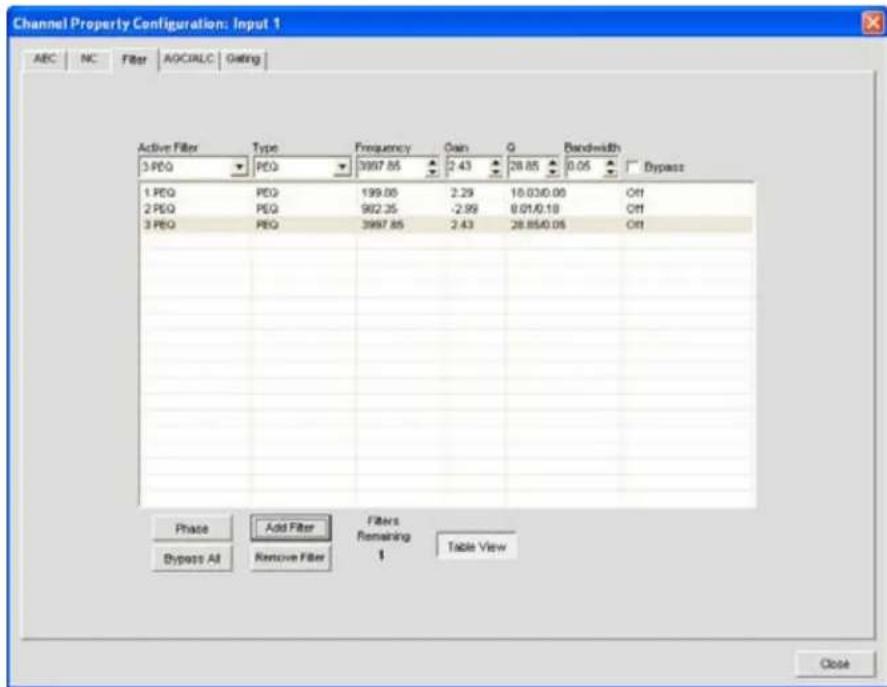
For additional information, refer to the Table of Contents for these related topics:
Channel Tab Overview•
AEC (Acoustic Echo Cancellation)
AGC/ALC (Automatic Gain Control/Automatic Level Control)
NC (Noise Cancellation)
Mic Gating•
Mic Input Settings
AGC/ALC (AUTOMATIC GAIN CONTROL/AUTOMATIC LEVEL CONTROL) TAB
AGC/ALC enables AGC or ALC and allows you to configure AGC settings for the selected input channel. Either AGC or ALC can be enabled—you cannot use them both at the same time.
AGC keeps an input signal at a target gain level that you select, and is generally used for Line Input channels.
ALC automatically keeps an input signal at a constant level, and is generally used to keep speech levels constant on Mic Input channels.
Accessing AGC/ALC
With the Channel tab selected on the Tab Bar, select the desired Mic input channel on the Tree View tab in the Site Pane, and press either the AGC or ALC button (located just below the Post Gain meter).
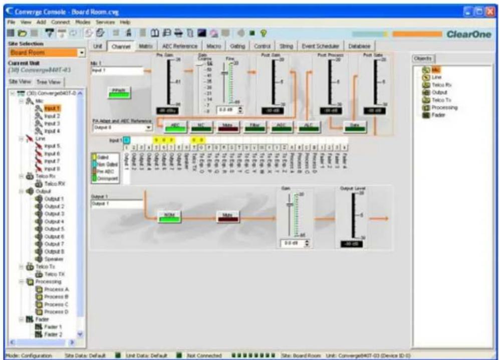
flowchart
graph TD
    A["Input 1: Non Gated"] --> B["Pre Gated"]
    C["Input 2: Non Gated"] --> D["Pre Gated"]
    E["Input 3: Non Gated"] --> F["Pre Gated"]
    G["Input 4: Non Gated"] --> H["Pre Gated"]
    I["Input 5: Non Gated"] --> J["Pre Gated"]
    K["Input 6: Non Gated"] --> L["Pre Gated"]
    M["Input 7: Non Gated"] --> N["Pre Gated"]
    O["Input 8: Non Gated"] --> P["Pre Gated"]
    Q["Input 9: Non Gated"] --> R["Pre Gated"]
    S["Input 10: Non Gated"] --> T["Pre Gated"]
    U["Input 11: Non Gated"] --> V["Pre Gated"]
    W["Input 12: Non Gated"] --> X["Pre Gated"]
    Y["Input 13: Non Gated"] --> Z["Pre Gated"]
    AA["Input 14: Non Gated"] --> AB["Pre Gated"]
    AC["Input 15: Non Gated"] --> AD["Pre Gated"]
    AE["Input 16: Non Gated"] --> AF["Pre Gated"]
    AG["Input 17: Non Gated"] --> AH["Pre Gated"]
    AI["Input 18: Non Gated"] --> AJ["Pre Gated"]
    AK["Input 19: Non Gated"] --> AL["Pre Gated"]
    AM["Input 20: Non Gated"] --> AN["Pre Gated"]
    AO["Input 21: Non Gated"] --> AP["Pre Gated"]
    AQ["Input 22: Non Gated"] --> AR["Pre Gated"]
    AS["Input 23: Non Gated"] --> AT["Pre Gated"]
    AU["Input 24: Non Gated"] --> AV["Pre Gated"]
    AW["Input 25: Non Gated"] --> AX["Pre Gated"]
    AY["Input 26: Non Gated"] --> AZ["Pre Gated"]
    BA["Input 27: Non Gated"] --> BB["Pre Gated"]
    BC["Input 28: Non Gated"] --> BD["Pre Gated"]
    BE["Input 29: Non Gated"] --> BF["Pre Gated"]
    BG["Input 30: Non Gated"] --> BH["Pre Gated"]
    BI["Input 31: Non Gated"] --> BJ["Pre Gated"]
    BK["Input 32: Non Gated"] --> BL["Pre Gated"]
    BM["Input 33: Non Gated"] --> BN["Pre Gated"]
    BO["Input 34: Non Gated"] --> BP["Pre Gated"]
    BZ["Output 1: Non Gated"] --> CA["Non-Gated"]
    CB["Output 2: Non Gated"] --> CD["Non-Gated"]
    CE["Output 3: Non Gated"] --> CF["Non-Gated"]
    CG["Output 4: Non Gated"] --> DH["Non-Gated"]
    DI["Output 5: Non Gated"] --> DJ["Non-Gated"]
    DK["Output 6: Non Gated"] --> DL["Non-Gated"]
    DM["Output 7: Non Gated"] --> DE["Non-Gated"]
    FD["Output 8: Non Gated"] --> DF["Non-Gated"]
    DG["Telco Rx: Non Gated"] --> DH
    DH --> DH
    DH --> DH
    DH --> DH
    DH --> DH
    DH --> DH
    DH --> DH
    DH --> DH
    DH --> DH
    DH --> DH
    DH --> DH
    DH --> DH
    DH --> DH
    DH --> DH
    DH --> DH
    DH --> DH
    DH --> DH
    DH --> DH
    DH --> DH
    DH --> DH
    DH --> DH
    BH --> BH
    BH --> BH
    BH --> BH
    BH --> BH
    BH --> BH
    BH --> BH
    BH --> BH
    BH --> BH
    BH --> BH
    BH --> BH
    BH --> BH
    BH --> BH
    BH --> BH
    BH --> BH
    BH --> BH
    BH --> BH
    BH --> BH
    BH --> BH
    BH --> BH
    BH --> BH
    BH --> DH
The Channel Property Configuration screen appears with the AGC/ALC tab selected as shown below:

Use the AGC/ALC radio buttons to select Off, ALC, or AGC. The default is Off. ALC is performed automatically; there are no user-configurable settings for ALC.
NOTE: AGC occurs after gain and filter settings in the audio signal path.
The configuration controls for AGC are described in the following sections.
Maximum Gain Slider
Set the Target Level first, then set the Maximum Gain that you want the AGC to apply to the signal. Maximum Gain is set using an RMS (Root Mean Square) level, which is the average magnitude of the audio signal over time. Maximum Gain range is 0 to 18dB in 1dB steps. The default value is 6dB.
Target Level Slider
Target Level (RMS) sets dB level for AGC to maintain. Target Level range is from -30 to 20dB in 1dB steps. The default target level is 0dB.
Active Gain Meter
The Active Gain Meter displays the gain adjustment being applied to the channel by AGC.
Response Time Slider
Response Time sets the amount of time (in milliseconds) over which the level is averaged before AGC is activated or deactivated.
Threshold Slider
Threshold sets the dB level at which AGC engages. The Threshold is set using an RMS (Root Mean Square) level, which is the average magnitude of the audio signal over time.
NOTE: Setting the Threshold above the background noise level will prevent AGC from amplifying background noise.
For additional information, refer to the Table of Contents for these related topics:
Channel Tab Overview•
AEC (Acoustic Echo Cancellation)
NC (Noise Cancellation) •
Mic Gating•
Filters•
Line Input Settings•
Mic Input Settings•
MIC GATING
The Gate button on the Channel tab enables you to configure gating control for individual Mic Input channels, and assign them to Gating Groups. There are two types of gating for Mic Input channels: Auto Gating and Manual Gating.
For more information about Gating Groups, see the Gating Tab section.
Accessing Channel Gating Configurations
With the Channel tab selected on the Tab Bar, select the desired Mic Input channel on the Tree View tab in the Site Pane, and press the Gate button (located just below the Post Process meter).
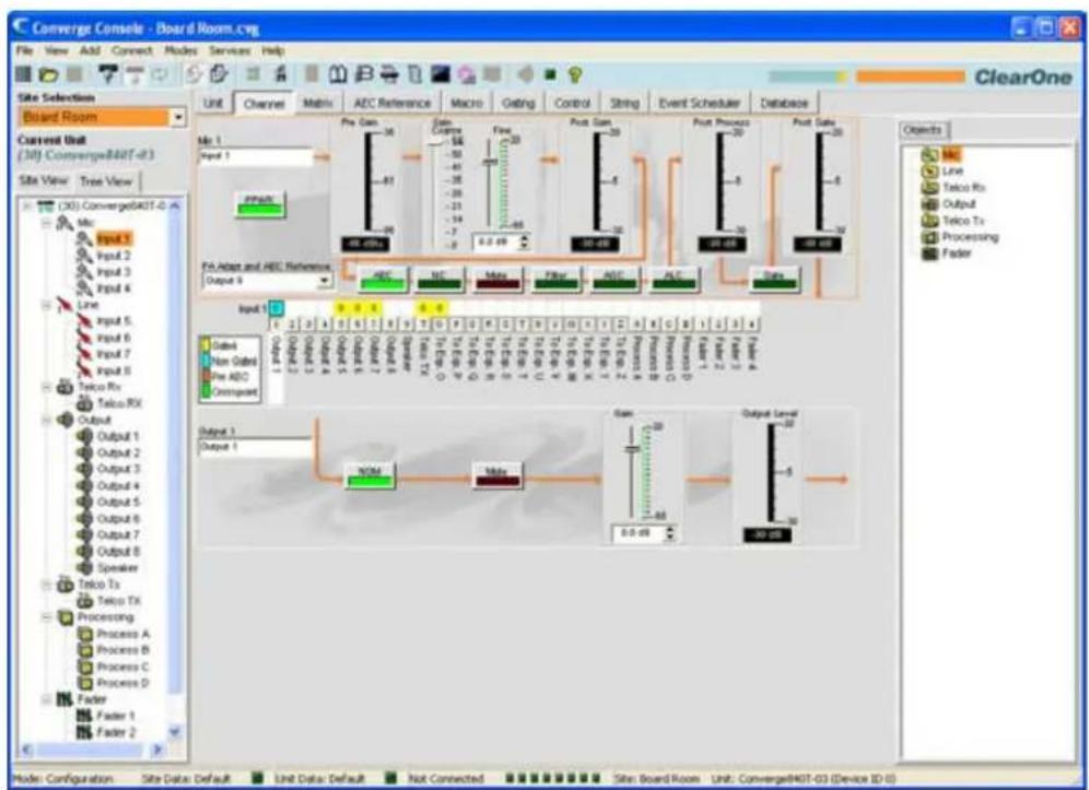
flowchart
graph TD
    A["Input 1"] --> B["Pre Gain: -36"]
    B --> C["Gain Charge: -58"]
    C --> D["Flow: -20"]
    D --> E["Punt Gain: -20"]
    E --> F["Punt Process: -20"]
    F --> G["Punt Data: -20"]
    G --> H["Output 1"]
    H --> I["NOM"]
    I --> J["Output Label: -20"]
    J --> K["Output 2"]
    K --> L["Non Gads"]
    L --> M["Pre ADC"]
    M --> N["Ompstead"]
    N --> O["Output 1"]
    O --> P["Output 2"]
    P --> Q["Non Gads"]
    Q --> R["Pre ADC"]
    R --> S["Ompstead"]
    S --> T["Output 1"]
    T --> U["NOM"]
    U --> V["Output Label: -20"]
    V --> W["Output 2"]
    W --> X["Non Gads"]
    X --> Y["Pre ADC"]
    Y --> Z["Ompstead"]
The Channel Property Configuration screen appears with the Gating tab selected.
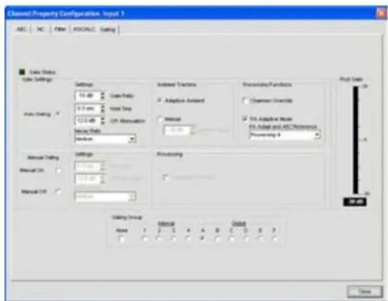
Use the radio buttons to select Auto Gating, Manual On or Manual Off, which are described in the sections below.
Gating Settings: Auto Gating
The upper section of the Gate Settings section of the screen contains the gating controls for Auto Gating as shown below.
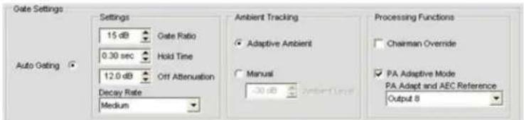
Auto Gating: Settings
- Gate Ratio: Specifies how much louder than the ambient level the audio level must be before the channel automatically gates on. The gate ratio range is from 0 to 50dB. The default is 15dB.
- Hold Time: Determines how long the channel stays gated on after the audio falls below the Gate Ratio threshold. The hold time range is from .1 to 8.0 seconds. The default is .3 seconds.
- Off Attenuation: Sets the amount of level reduction applied to a channel when it is gated off. The range is from 0 to 60dB. The default is 12dB.
- Decay Rate: Determines how fast a channel gates off after the Hold Time expires. The default is Medium.
NOTE: Changing Hold Time, Off Attenuation, and Decay Rate also changes the same settings under Manual Gating.
Auto Gating: Ambient Tracking
- Adaptive Ambient: Adjusts the ambient reference level as noise and room conditions change. When Adaptive Ambient is on, the mic channel monitors the ambient noise level on the input and adjusts the ambient level reference automatically. This means that the gate threshold level automatically increases or decreases based on background noise. The default is On.
- Manual: When Adaptive Ambient is set to Manual, the input will use the fixed ambient level you specify in the Ambient Level field as its gating reference.
Auto Gating: Processing Functions
- Chairman Override: Provides gating priority for this mic input over any other mic input within the same gating control (mixer) group. When a mic with Chairman Override enabled gates on, all mics which do not have Chairman Override enabled will gate off. The default is Off.
- PA Adaptive Mode: Uses the audio level on a specified output as the new ambient level when audio is present at the power amplifier. This prevents loudspeaker audio from gating on the mic while still allowing people in the room to gate on microphones when they speak (provided that their voices are louder than the loudspeaker audio). For example, you might decide to play background music from a CD player during a presentation. PA Adaptive Mode allows you to use the output routed from the CD player as the ambient reference to prevent the CD player's audio from gating on microphones. The default is on.
- PA Adapt and AEC Reference: When PA Adaptive Mode is selected, you must define the output that will be used as the reference source for PA adaptation and Acoustic Echo Cancellation (AEC). Select a source in the PA Adapt and AEC Reference drop-down list. You can use any one of the outputs, expansion bus references, virtual references, or speaker output channels as the reference.
Gate Settings: Manual Gating
The lower section of the Gate Settings section of the screen contains gating configuration controls for Manual Gating as shown below.
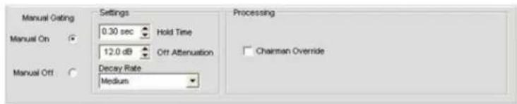
Manual Gating: Manual On/Manual Off
Select the Manual On radio button to gate the channel on, or Manual Off to gate the channel off. Off gating behavior is controlled by the settings described in the next section.
Manual Gating: Settings
- Hold Time: Determines how long the channel stays gated on after the channel is manually gated off. The hold time range is from .1 to 8.0 seconds. The default is .3 seconds.
- Off Attenuation: Sets the amount of level reduction applied to a channel when it is manually gated off. The range is from 0 to 50dB. The default is 12dB.
- Decay Rate: Determines how fast a channel gates off after the Hold Time expires. The default is Medium.
NOTE: Changing Hold Time, Off Attenuation, and Decay Rate also changes the same settings under Auto Gating.
Both Auto Gating and Manual Gating are affected by Gating Group membership as described in the next section.
Gating Groups
In addition to specifying gating characteristics for each Mic Input channel, you can assign the channel to a Gating Group for greater flexibility and control. When inputs are assigned to a gating group, the gating information from the inputs is used to control how the entire mixer behaves. Gating Groups are created and defined using the Gating Tab on the Tab Bar in Console.
The 880, 880T, 880TA 840T, 8i, SR 1212 and SR 1212A feature four internal gating groups (Internal 1–4) and six global gating groups across the expansion bus (Global A–F). Mic Inputs can only be used in one gating group at a time. If an input is not assigned to a gating group, that mic's gating properties are independent, and they have no effect on any gating group. When gating groups span two or more units (global gating groups), the settings must be the same for each unit attached to the global gating group.
NOTE: Input channels can be assigned to one and only one Gating Group at a time.
Mic Inputs are routed to Global Group A by default. To assign a gating group, select an Internal or Global radio button in the Gating Group section of the screen, or select None to have the Mic Input gate independently of any gating group.
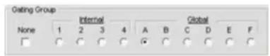
Post Gate Meter
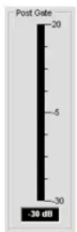
The Post Gate Meter displays the audio level of the selected channel after Auto or Manual Gating settings are applied. Meter range is from -30 to +20dB.
For more information, refer to the Table of Contents for these related topics:
Gating Tab•
AEC (Acoustic Echo Cancellation)
AGC/ALC (Automatic Gain Control/Automatic Level Control)
NC (Noise Cancellation)
Filters•
Line Input Settings•
Mic Input Settings•
MIC INPUT SETTINGS
Mic Input Settings enable you to customize mic input channel settings using the Channel screen.
Accessing Mic Input Settings
With the Channel tab selected on the Tab Bar, select the desired mic input channel on the Tree View tab in the Site Pane.
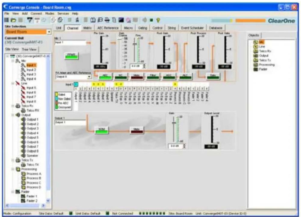
flowchart
graph TD
    A["Input 1: Non-Delay"] --> B["Add"]
    C["Add"] --> D["Output 1: Non-Delay"]
    E["Output 1: Non-Delay"] --> F["Add"]
    G["Output 1: Non-Delay"] --> H["Output Level: -5"]
    I["Input 2: Non-Delay"] --> J["Add"]
    K["Input 2: Non-Delay"] --> L["Output 2: Non-Delay"]
    M["Input 3: Non-Delay"] --> N["Add"]
    O["Input 3: Non-Delay"] --> P["Output 3: Non-Delay"]
    Q["Input 4: Non-Delay"] --> R["Add"]
    S["Input 4: Non-Delay"] --> T["Output 4: Non-Delay"]
    U["Input 5: Non-Delay"] --> V["Add"]
    W["Input 5: Non-Delay"] --> X["Output 5: Non-Delay"]
    Y["Input 6: Non-Delay"] --> Z["Add"]
    AA["Input 6: Non-Delay"] --> AB["Output 6: Non-Delay"]
    AC["Input 7: Non-Delay"] --> AD["Add"]
    AE["Input 7: Non-Delay"] --> AF["Output 7: Non-Delay"]
    AG["Input 8: Non-Delay"] --> AH["Add"]
    AI["Input 8: Non-Delay"] --> AJ["Output 8: Non-Delay"]
    AK["Input 9: Non-Delay"] --> AL["Add"]
    AM["Input 9: Non-Delay"] --> AN["Output 9: Non-Delay"]
    AO["Input 10: Non-Delay"] --> AP["Add"]
    AQ["Input 10: Non-Delay"] --> AR["Output 10: Non-Delay"]
    AS["Input 11: Non-Delay"] --> AT["Add"]
    AU["Input 11: Non-Delay"] --> AV["Output 11: Non-Delay"]
    AW["Input 12: Non-Delay"] --> AX["Add"]
    AY["Input 13: Non-Delay"] --> AZ["Output 13: Non-Delay"]
    BA["Input 14: Non-Delay"] --> BB["Add"]
    BC["Input 15: Non-Delay"] --> BD["Output 15: Non-Delay"]
    BE["Input 16: Non-Delay"] --> BF["Add"]
    BG["Input 17: Non-Delay"] --> BH["Output 17: Non-Delay"]
    BI["Input 18: Non-Delay"] --> BJ["Add"]
    BK["Input 19: Non-Delay"] --> BL["Output 19: Non-Delay"]
    BM["Input 20: Non-Delay"] --> BN["Add"]
    BO["Input 21: Non-Delay"] --> BP["Output 21: Non-Delay"]
    BQ["Input 22: Non-Delay"] --> BR["Add"]
    BS["Input 23: Non-Delay"] --> BT["Output 23: Non-Delay"]
    BU["Input 24: Non-Delay"] --> BV["Add"]
    BW["Input 25: Non-Delay"] --> BX["Output 25: Non-Delay"]
    BY["Input 26: Non-Delay"] --> BZ["Add"]
    CA["Input 27: Non-Delay"] --> CB["Output 27: Non-Delay"]
    CC["Input 28: Non-Delay"] --> CD["Add"]
    CE["Input 29: Non-Delay"] --> CF["Output 29: Non-Delay"]
    DG["Input 30: Non-Delay"] --> DH["Add"]
    DI["Input 31: Non-Delay"] --> DJ["Output 31: Non-Delay"]
    DK["Input 32: Non-Delay"] --> DL["Add"]
    DV["Input 33: Non-Delay"] --> DW["Output 33: Non-Delay"]
    DX["XOM"] --> DY
    DXX["XOM"] --> DY
    DY["XOM"] --> DY
    DY["XOM"] --> DY
    DY["XOM"] --> DY
    DY["XOM"] --> DY
    DY["XOM"] --> DY
    DY["XOM"] --> DY
    DY["XOM"] --> DY
    DY["XOM"] --> DY
    DY["XOM"] --> DY
    DY["XOM"] --> DY
    DY["XOM"] --> DY
    DY["XOM"] --> DY
    DY["XOM"] <--> DY["XOM"]
The center pane displays a signal processing diagram, meters, and configuration controls for the selected mic input channel as shown above. Note that the meters and configuration controls are shown at the appropriate point in the signal path.
The meters and configuration controls for mic input channels are explained in the following sections.
Channel Label
Rename the channel by entering a name in the Label entry field (optional). Label changes are global, and appear throughout Console wherever the label is referenced.
PPWR (Phantom Power)

The PPWR (Phantom Power) button toggles phantom power on and off. Phantom power is an auxiliary power source used to power certain types of microphones. Phantom power voltage is 24VDC. The default is On.
Pre Gain Meter
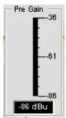
The Pre Gain meter displays the mic input level before gain adjustments. Meter range is determined by the Coarse Gain Slider in the Gain section of the screen as described below.
NOTE: All meters in Console are peak-level meters.
Gain Section
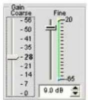
The Coarse and Fine gain sliders are used to match the level settings between mic inputs, and to adjust the volume level for a given mic input channel. The Min/Max fine gain sliders are used to set minimum and maximum gain settings, and to report min/max gain settings via serial commands.
In general, you should set the Coarse gain slider to 56dB for a mic input, 28dB for active equipment that requires an input between mic and line level, or 0dB for a line level input device.
Use the Fine gain slider to adjust input volume level. You can also set fine gain in .5dB increments using the Up/Down buttons, or enter a value directly in the field.
Post Gain Meter
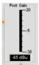
The Post Gain Meter displays the audio level after gain adjustments.
Post Process Meter
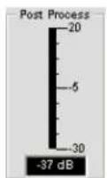
The Post Process Meter displays the audio level after it passes through all mic input processing, such as Processing channels, Filters, AEC, NC, AGC/ALC, and Mute.
Post Gate Meter
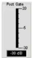
The Post Gate Meter displays the audio level after gating. Channel gating for mic inputs is configured on the Gating tab of the Channel Property Configuration window for mic input channels, which is described in the next section.
Channel Configuration Buttons

The Channel Configuration Buttons enable you to configure the available features for mic input channels. With the exception of the Mute button, which toggles muting, clicking a channel configuration button displays the Channel Property Configuration window. Each feature is shown on a tab in the window that corresponds with the configuration button shown in the Center Pane.
For example, clicking the AEC button displays the Channel Property configuration window with the AEC tab selected as shown below:
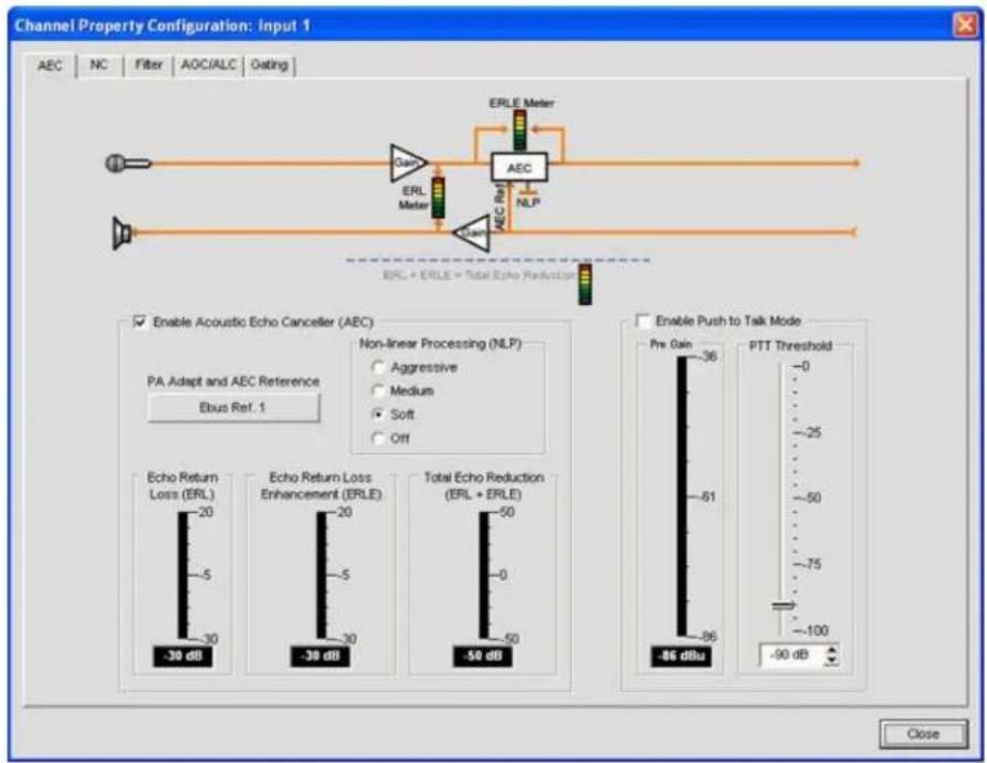
For more information on each configuration feature, see the following topics:
AEC (Acoustic Echo Cancellation)
AGC/ALC (Automatic Gain Control/Automatic Level Control)
NC (Noise Cancellation)
Mic Gating•
Filters•
Channel Routing Matrix: Inputs
The channel routing matrix section of the Channel screen shows the matrix row and audio routing configuration for the selected input channel (mic input 1 in this case). Clicking a cross point box selects it, clicking it a second time sets the cross point, as indicated by a colored box. The dB level for set cross points is shown numerically in the box.

To adjust cross point gain/attenuation, right-click on a cross point box and select Cross Point from the shortcut menu.
The Cross Point Attenuation slider appears. Move the slider or use the selector box to set the gain/attenuation level in dB. The range is from -60 to 12dB in .5dB increments. The default is 0dB. Note that the level to the nearest dB is displayed in the cross point for the channel on the Matrix.
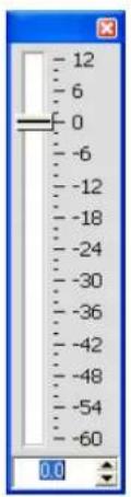
NOTE: Your changes are automatically saved when you close the slider.
Expanded Channel Routing Matrix
In the channel routing matrix, pressing the button underneath an Output, Process, or Fader cross point box displays the signal flow diagram and configuration controls for that channel. For example, clicking on Output 5 displays the routing configuration for output channel 5 as shown below.
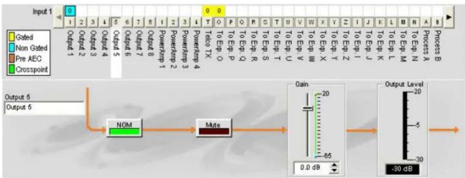
flowchart
graph LR
    A["Input 1: Gated"] --> B["Output 1: Non Gated"]
    B --> C["Output 2: Gated"]
    C --> D["Output 3: Non Gated"]
    D --> E["Output 4: Gated"]
    E --> F["Output 5: Non Gated"]
    F --> G["Output 6: Gated"]
    G --> H["Output 7: Gated"]
    H --> I["Output 8: Gated"]
    I --> J["Output 9: Gated"]
    J --> K["Output 10: Gated"]
    K --> L["Output 11: Gated"]
    L --> M["Output 12: Gated"]
    M --> N["Output 13: Gated"]
    N --> O["Output 14: Gated"]
    O --> P["Output 15: Gated"]
    P --> Q["Output 16: Gated"]
    Q --> R["Output 17: Gated"]
    R --> S["Output 18: Gated"]
    S --> T["Output 19: Gated"]
    T --> U["Output 20: Gated"]
    U --> V["Output 21: Gated"]
    V --> W["Output 22: Gated"]
    W --> X["Output 23: Gated"]
    X --> Y["Output 24: Gated"]
    Y --> Z["Output 25: Gated"]
    Z --> AA["Output 26: Gated"]
    AA --> AB["Output 27: Gated"]
    AB --> AC["Output 28: Gated"]
    AC --> AD["Output 29: Gated"]
    AD --> AE["Output 30: Gated"]
    AE --> AF["Output 31: Gated"]
    AF --> AG["Output 32: Gated"]
    AG --> AH["Output 33: Gated"]
    AH --> AI["Output 34: Gated"]
    AI --> AJ["Output 35: Gated"]
    AJ --> AK["Output 36: Gated"]
    AK --> AL["Output 37: Gated"]
    AL --> AM["Output 38: Gated"]
    AM --> AN["Output 39: Gated"]
    AN --> AO["Output 40: Gated"]
    AO --> AP["Output 41: Gated"]
    AP --> AQ["Output 42: Gated"]
    AQ --> AR["Output 43: Gated"]
    AR --> AS["Output 44: Gated"]
    AS --> AT["Output 45: Gated"]
    AT --> AU["Output 46: Gated"]
    AU --> AV["Output 47: Gated"]
    AV --> AW["Output 48: Gated"]
    AW --> AX["Output 49: Gated"]
    AX --> AY["Output 50: Gated"]
    AY --> AZ["Output 51: Gated"]
    AZ --> BA["Output 52: Gated"]
    BA --> BB["Output 53: Gated"]
    BB --> BC["Output 54: Gated"]
    BC --> BD["Output 55: Gated"]
    BD --> BE["Output 56: Gated"]
    BE --> BF["Output 57: Gated"]
    BF --> BG["Output 58: Gated"]
    BG --> BH["Output 59: Gated"]
    BH --> BI["Output 60: Gated"]
    BI --> BJ["Output 61: Gated"]
    BJ --> BK["Output 62: Gated"]
    BK --> BL["Output 63: Gated"]
    BL --> BM["Output 64: Gated"]
    BM --> BN["Output 65: Gated"]
    BN --> BO["Output 66: Gated"]
    BO --> BP["Output 67: Gated"]
    BP --> BQ["Output 68: Gated"]
    BQ --> BR["Output 69: Gated"]
    BR --> BS["Output 70: Gated"]
    BS --> BT["Output 71: Gated"]
    BT --> BU["Output 72: Gated"]
    BU --> BV["Output 73: Gated"]
    BV --> BW["Output 74: Gated"]
    BW --> BX["Output 75: Gated"]
    BX --> BY["Output 76: Gated"]
    BY --> BZ["Output 77: Gated"]
    BZ --> CA["Output 78: Gated"]
    CA --> CB["Output 79: Gated"]
    CB --> CC["Output 80: Gated"]
    CC --> CD["Output 81: Gated"]
    CD --> CE["Output 82: Gated"]
    CE --> CF["Output 83: Gated"]
    CF --> CG["Output 84: Gated"]
    CG --> CH["Output 85: Gated"]
    CH --> CI["Output 86: Gated"]
    CI --> CJ["Output 87: Gated"]
    CJ --> CK["Output 88: Gated"]
    CK --> CL["Output 89: Gated"]
    CL --> CM["Output 90: Gated"]
    CM --> CN["Output 91: Gated"]
    CN --> CO["Output 92: Gated"]
    CO --> CP["Output 93: Gated"]
    CP --> CQ["Output 94: Gated"]
    CQ --> CR["Output 95: Gated"]
    CR --> CS["Output 96: Gated"]
    CS --> CT["Output 97: Gated"]
    CT --> CU["Output 98: Gated"]
    CU --> CV["Output 99: Gated"]
    CV --> CW[Output 100: Gain = -65 dB / -30 dB Output Level = -20 dB / -5 dB / -30 dB Output Level = -30 dB / -30 dB Output Level = -20 dB / -5 dB / -30 dB Output Level = -20 dB / -5 dB / -30 dB Output Level = -20 dB / -5 dB / -30 dB Output Level = -20 dB / -5 dB / -30 dB Output Level = -20 dB / -5 dB / -30 dB Output Level = -20 dB / -5 dB / -30 dB Output Level = -20 dB / -5 dB / -5 dB / -30 dB Output Level = -20 dB / -5 dB / -5 dB / -5 dB / -5 dB / -5 dB / -5 dB / -5 dB / -5 dB / -5 dB / -5 dB / -5 dB / -5 dB / -5 dB / -5 dB / -5 dB / -5 dB / -5 dB / -5 dB / -5 dB / -5 dB / -5 dB / -5 dB / -5 dB / -5 dB / -5 dB / -10 dB / -10 dB (Gated) |
This display is identical to that shown in Channel when the output channel is selected in the Tree View pane. See Output Settings for more information.
You can change the channel Label (name) of the output channel in the label entry field; toggle NOM constant gain on or off; toggle Mute on or off; and use the Gain slider to set the gain level for the channel. The Output Level meter shows the level for the channel in real time as you make configuration changes.
NOTE: Changes to channel configuration settings made in the channel routing matrix apply globally to that channel. For example, changing the label (name) from "Output 1" to "Ceiling Speakers" changes the name of the output channel in the Tree View pane, and everywhere else the label appears in Console.
Creating Channel Objects
One of the most powerful features of Console is the ability to create Audio Devices and Channel Objects. Channel objects contain all settings for the channel at the time the object is created. After configuring an input using the Channel tab as described in this topic, you can save it into the database, and use drag and drop configuration to streamline configuration tasks.
To save an input channel configuration, right click in the Channel screen (anywhere above the channel routing matrix). From the shortcut menu that appears, select Export Object as shown below.
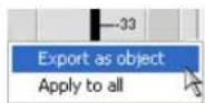
NOTE: You can apply the channel configurations for the current channel to all channels of the same type by selecting the Apply to all option. Use this option with caution because there is no way to undo the changes.
Enter an appropriate Label (name) in the entry field of Export Object dialog as shown below.
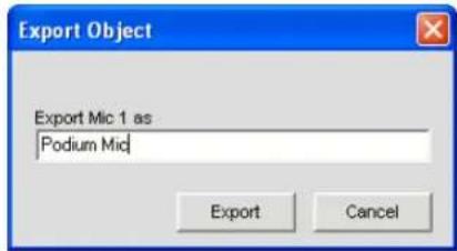
Click Export to save the configuration to the database, or Cancel to return to the Channel screen.
Console saves the object to the database and displays it in the Object Tree pane as shown below.
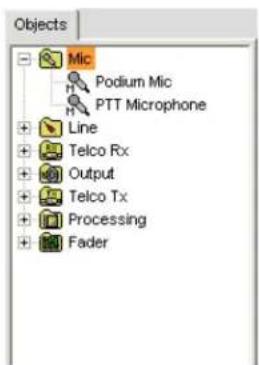
For more information on using audio devices and channel objects, refer to the Table of Contents for the following topics:
AV Devices• Creating AV Devices• Channel Objects• Database Tab• Drag & Drop Configuration•
Optimizing Input Gain Structure
Optimizing gain structure for input channels maximizes the signal-to-noise ratio for the channel and ensures optimal audio performance. Before configuring an input channel, ClearOne recommends that you review the Optimizing Gain Structure topic.
For additional information, refer to the Table of Contents for these related topics:
Channel Tab Overview AGC/ALC (Automatic Gain Control/Automatic Level Control) Mic Gating Gating Tab Matrix Tab Drag & Drop Configuration Database Tab Line Input Settings Output Settings
LINE INPUT SETTINGS
Line Input Settings enable you to customize line input channel settings. All settings for a given line input are available on the Channel screen.
Accessing Line Input Settings
With the Channel tab selected on the Tab Bar, select the desired line input channel on the Tree View tab in the Site Pane.
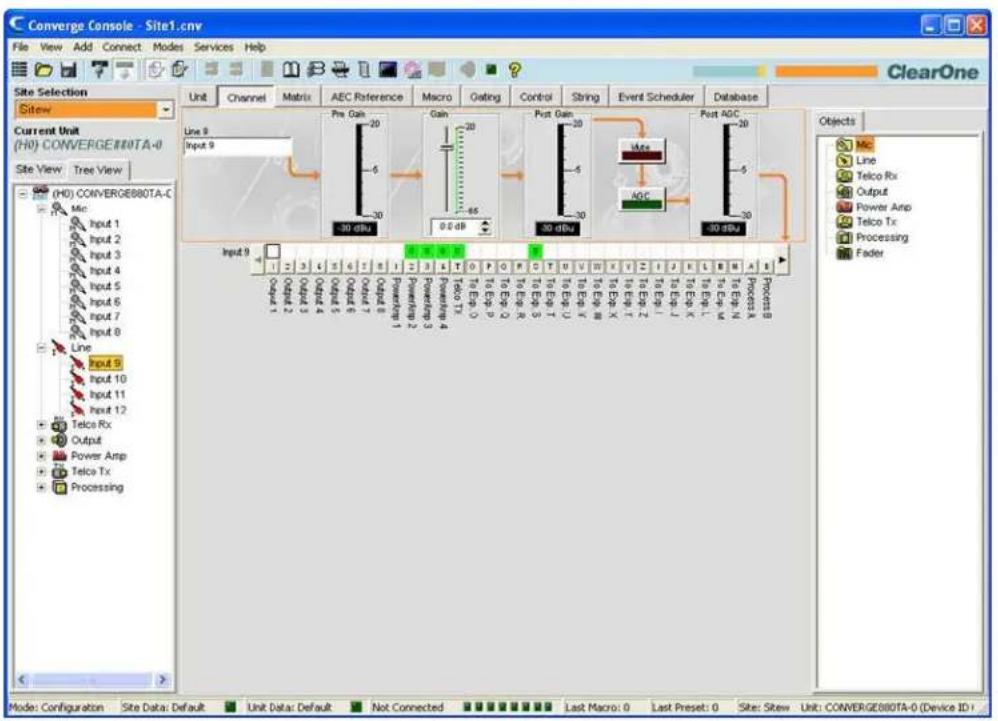
The Center Pane displays a signal processing diagram, meters, and configuration controls for selected line input channel as shown above. Note that the meters and configuration controls are shown at the appropriate point in the signal path.
The meters and configuration controls for line inputs are explained in the following sections.
Channel Label
Rename the channel by entering a name in the Label entry field (optional). Label changes are global, and appear throughout Console wherever the label is referenced.
Pre Gain Meter
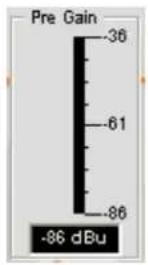
The Pre Gain Meter shows the line input level before gain adjustments.
NOTE: All meters in Console are peak-level meters.
Gain Slider
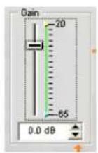
The Gain Slider adjusts the line input volume level. The Min/Max fine gain sliders are used to set minimum and maximum gain settings, and to report min/max gain settings via serial commands. You can also set the gain in .5dB increments using the Up/Down buttons, or enter a value directly in the field.
Post Gain Meter
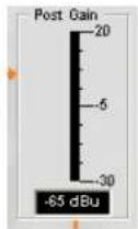
The Post Gain Meter shows the input level after gain adjustments.
Mute Button
Clicking the Mute button toggles muting. The default is Off.
AGC (Automatic Gain Control) Button
Clicking the AGC (Automatic Gain Control) button displays the Channel Property Configuration dialog for the selected input channel as shown below.
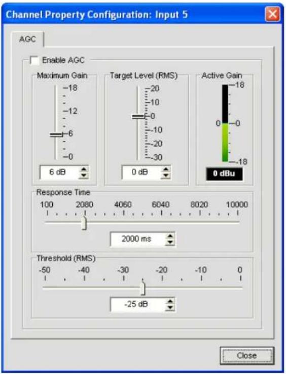
Select the Enable AGC checkbox to enable AGC, or deselect it to disable AGC. For AGC configuration details, see AGC Configuration Settings.
Channel Routing Matrix: Line Inputs
The channel routing matrix shows the associated matrix row and audio routing configuration for the selected input channel (line input 5 in this case). Clicking a cross point box selects it, clicking it a second time sets the cross point, as indicated by a green box. The dB level for set cross points is shown numerically in the box.

To adjust cross point gain/attenuation, right-click on a cross point box and select Cross Point from the shortcut menu.
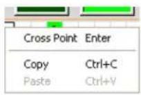
The Cross Point Attenuation slider appears. Move the slider or use the selector box to set the gain/attenuation level in dB. The range is from -60 to 12dB in .5dB increments. The default is 0dB.
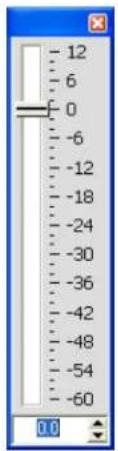
NOTE: Your changes are automatically saved when you close the slider.
Channel Routing Matrix: Outputs, Processing, Faders
In the channel routing matrix, pressing the button underneath an Output, Process, or Fader cross point box displays the signal flow diagram and configuration controls for that channel. For example, clicking on Output 5 displays the routing configuration for output channel 5 as shown below.
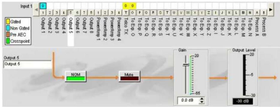
flowchart
graph LR
    A["Input 1"] --> B["0"]
    B --> C["0"]
    C --> D["0"]
    D --> E["0"]
    E --> F["0"]
    F --> G["0"]
    G --> H["0"]
    H --> I["0"]
    I --> J["0"]
    J --> K["0"]
    K --> L["0"]
    L --> M["0"]
    M --> N["0"]
    N --> O["0"]
    O --> P["0"]
    P --> Q["0"]
    Q --> R["0"]
    R --> S["0"]
    S --> T["0"]
    T --> U["0"]
    U --> V["0"]
    V --> W["0"]
    W --> X["0"]
    X --> Y["0"]
    Y --> Z["0"]
    Z --> AA["0"]
    AA --> AB["0"]
    AB --> AC["0"]
    AC --> AD["0"]
    AD --> AE["0"]
    AE --> AF["0"]
    AF --> AG["0"]
    AG --> AH["0"]
    AH --> AI["0"]
    AI --> AJ["0"]
    AJ --> AK["0"]
    AK --> AL["0"]
    AL --> AM["0"]
    AM --> AN["0"]
    AN --> AO["0"]
    AO --> AP["0"]
    AP --> AQ["0"]
    AQ --> AR["0"]
    AR --> AS["0"]
    AS --> AT["0"]
    AT --> AU["0"]
    AU --> AV["0"]
    AV --> AW["0"]
    AW --> AX["0"]
    AX --> AY["0"]
    AY --> AZ["0"]
    AZ --> BA["0"]
    BA --> BB["0"]
    BB --> BC["0"]
    BC --> BD["0"]
    BD --> BE["0"]
    BE --> BF["0"]
    BF --> BG["0"]
    BG --> BH["0"]
    BH --> BI["0"]
    BI --> BJ["0"]
    BJ --> BK["0"]
    BK --> BL["0"]
    BL --> BM["0"]
    BM --> BN["0"]
    BN --> BO["0"]
    BO --> BP["0"]
    BP --> BQ["0"]
    BQ --> BR["0"]
    BR --> BS["0"]
    BS --> BT["0"]
    BT --> BU["0"]
    BU --> BV["0"]
    BV --> BW["0"]
    BW --> BX["0"]
    BX --> BY["0"]
    BY --> BZ["0"]
This display is identical to that shown in Channel when the output channel is selected in the Tree View pane. See Output Settings for more information.
You can change the channel Label (name) of the output channel in the label entry field; toggle NOM constant gain on or off; toggle Mute on or off; and use the Gain slider to set the gain level for the channel. The Output Level meter shows the level for the channel in real time as you make configuration changes.
NOTE: Changes to configuration settings made in the channel routing matrix apply globally to that channel. For example, changing the label (name) from "Output 1" to "Ceiling Speakers" changes the name of the output channel in the Tree View pane, and everywhere else the label appears in Console.
Creating Channel Objects
One of the most powerful features of Console is the ability to create Channel Objects. Channel objects capture all settings for the channel at the time the object is created. After configuring an input using the Channel tab as described in this topic, you can save it into the Database, and use drag and drop configuration to streamline configuration tasks.
To save an input channel configuration, right click in the Channel screen (anywhere above the channel routing matrix). From the shortcut menu that appears, select Export Object as shown below.
NOTE: You can apply the channel configurations for the current channel to all channels of the same type by selecting the Apply to all option. Use this option with caution because there is no way to undo the changes.
Enter an appropriate Label (name) in the entry field of Export Object dialog as shown below.
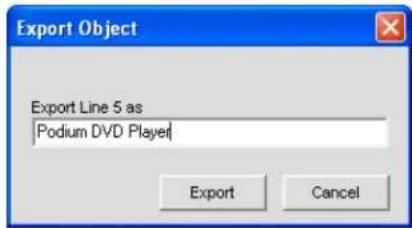
Click Export to save the configuration to the database, or Cancel to return to the Channel screen.
Console saves the object to the database and displays it in the Object Tree as shown below.
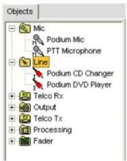
Optimizing Input Gain Structure
Optimizing gain structure for input channels maximizes the signal-to-noise ratio for the channel and ensures optimal audio performance. Before configuring an input channel, ClearOne recommends that you review the Optimizing Gain Structure topic.
For more information, refer to the Table of Contents for these related topics:
Channel Tab Overview•
AGC/ALC (Automatic Gain Control/Automatic Level Control)
Mic Gating•
Gating Tab·
Matrix Tab·
Drag & Drop Configuration•
Database Tab•
Mic Input Settings
Output Settings•
TELCO/VOIP RX SETTINGS
Telco/VoIP Rx Settings enable you to customize telephone receive channel settings using the Channel tab.
Accessing Telco/VoIP Rx Settings
With the Channel tab selected on the Tab Bar, select the Telco/VoIP Rx channel on the Tree View tab in the Site Pane.
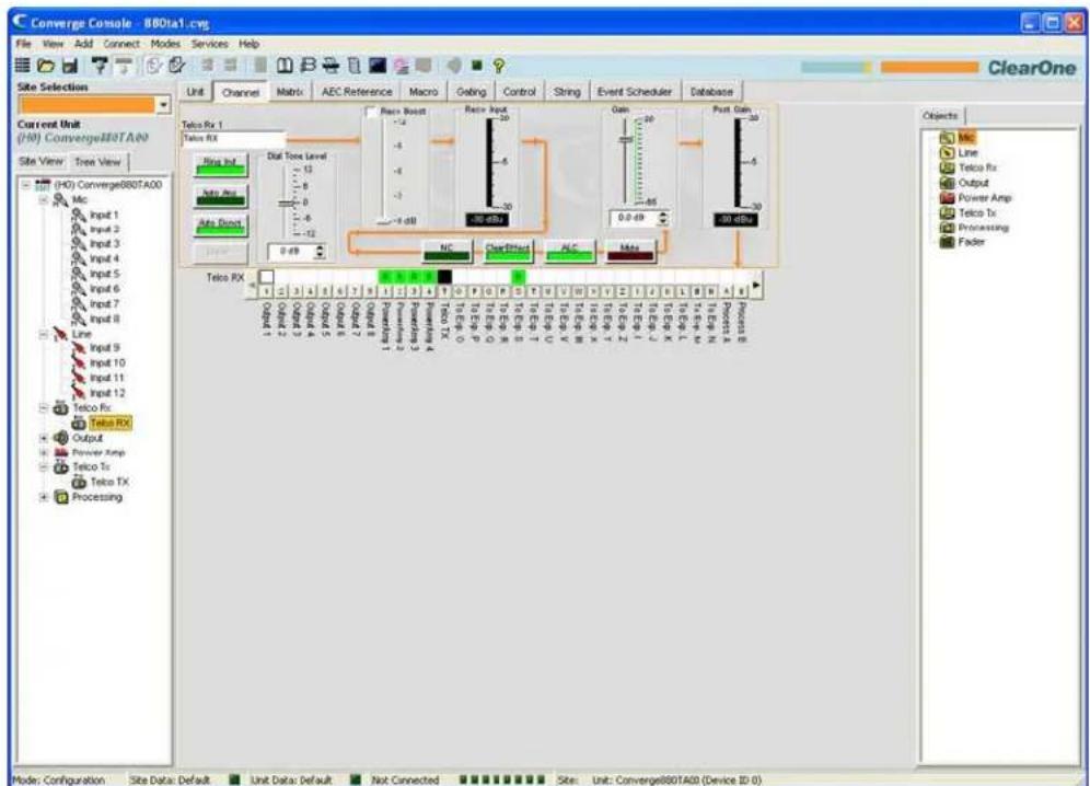
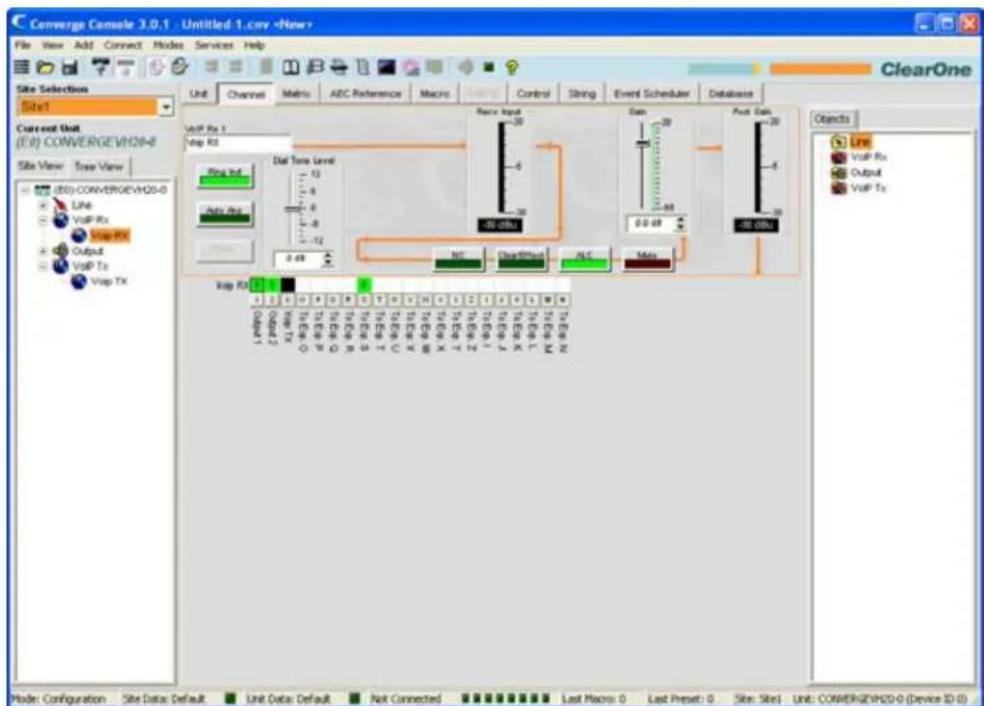
As shown above, the center pane displays a signal flow diagram for the telco/VoIP rx channel, real-time peak-level meters, as well as a channel routing matrix that displays the audio routing configuration for the channel. Note that the meters and configuration controls are shown at the appropriate point in the signal path.
The following sections describe how to use these controls (in order from left-to-right and top-to-bottom as they appear in the signal flow) to configure the telco receive channel settings for your installation.
Channel Label
Rename the channel by entering a name in the Label entry field (optional). Labels are shown throughout Console wherever the channel is referenced.
Channel Configuration Buttons
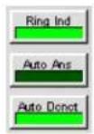

The Channel Configuration Buttons enable you to configure settings for the Telco/VoIP Rx channel. With the exception of the Mute, ClearEffect ^™ , and ALC buttons, which toggle their respective functions and have no user-configurable settings, clicking a channel configuration button displays the Channel Property Configuration window as shown below.
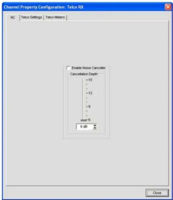
The window contains three tabs: NC (Noise Cancellation), Telco Settings, and Telco Meters, which are described in the following sections.
NC (Noise Cancellation) Tab
Select the Enable Noise Canceller checkbox to enable NC for the channel. Adjust the Cancellation Depth slider to the dB setting which provides the best combination of low noise and maximum speech clarity. The attenuation depth can be set in 1dB increments from 6dB to 15dB. The default is 6dB. The default for NC is off.
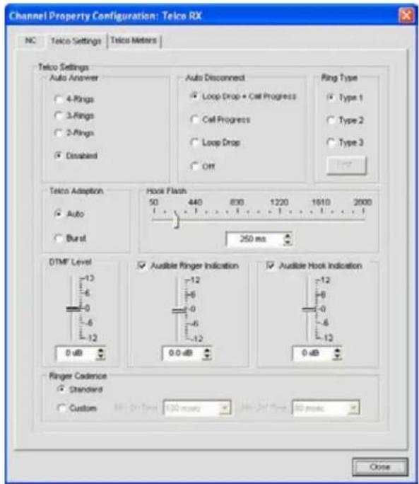
You can use noise cancellation on all types of input channels. See NC (Noise Cancellation) for more information.
Telco Settings Tab
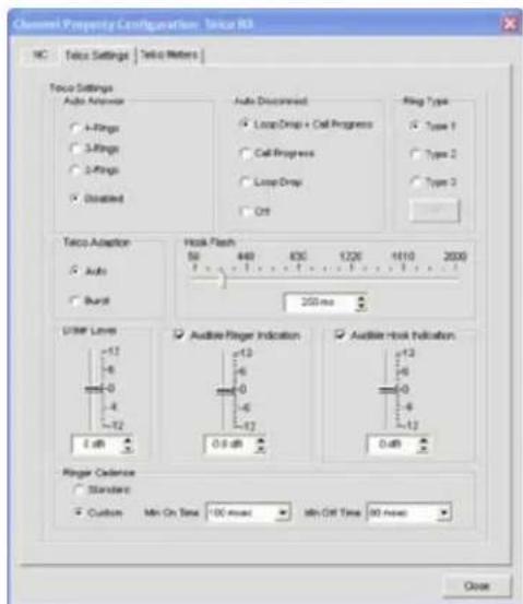
Settings available on the Telco Settings Tab include:
Auto Answer: Set the number of rings before the unit connects an incoming call (or disable the function). The default is Disabled.
Auto-Disconnect: Select the auto disconnect mode to control when the unit disconnects a connected call. Modes include Loop Drop + Call Progress, Call Progress, and Loop Drop, and Off. The default is Loop Drop + Call Progress. (Not used in VoIP Settings)
Ring Type: Select from three different ring tones (Type 1, Type 2, Type 3). To test a particular tone, click Test after you have selected the tone.
Note: VH20 Units have five selectable ring types.
Telco Adaptation: Some applications require the unit to adapt to line conditions using a white-noise burst (Noise) rather than automatically (Auto). The default is Auto. (Not used in VoIP Settings)
Hook Flash: Sends a momentary interruption in the line seizure, allowing activation of options such as 3-way calling, call waiting, and call hold. This feature is dependent on the services offered by your telephone company. You can set the duration of the hook flash using the slider or the selector box. Range is 50ms to 2 seconds in 10ms steps. The default is 250ms.
DTMF Level: This feature allows you to adjust the DTMF tone level in relationship to the participant audio level in the room. The level can be adjusted in 1dB steps from a nominal level of 0dB to plus or minus 12dB in 1dB increments. The default is 0dB.
Audible Ring Indication: When this feature is enabled, an audible ring is heard for incoming calls. The level adjustment allows you to customize the level in relationship to the participant audio level in the room. The level can be adjusted in 1dB steps from a nominal level 0 (default) to plus or minus 12dB in 1dB increments. The default is 0dB.
Audible Hook Indication: When the unit goes off hook (connects) a beep is injected into the receive channel and transmit channel of the unit. When the unit goes on hook (disconnects), a series of two beeps is injected into the receive channel to indicate that the call has been dropped.
Ringer Cadence: (Not used in VoIP Settings)
- Standard: Uses the cadence specified in the Country Code to detect the standard ring cadence per country.
- Custom: Set for distinctive ring cadences. When custom is set, the Min On and Min Off times must be selected from their respective drop-down boxes. PBX's can have distinctive ring cadences that are not country specific. These times are the minimum values the ring cadence must be for the unit to detect the ring. If the ring cadence signal provided by the PBX is greater than the custom settings, the unit will detect the ring.
Telco Meters Tab (Not available on the VH20)
The Telco Meters tab displays a round-trip signal flow diagram for the selected Telco Rx, as well as real-time level meters for the signal at each stage of processing. The settings on this tab cannot be modified.
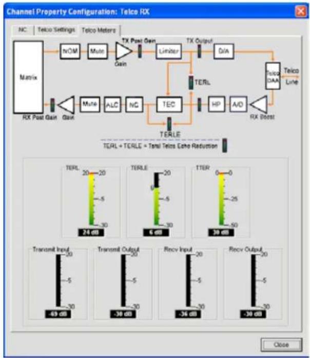
flowchart
graph TD
    A["Matrix"] --> B["NOM"]
    B --> C["Mute"]
    C --> D["TX Post Gain"]
    D --> E["Limiter"]
    E --> F["TX Output"]
    F --> G["D/A"]
    G --> H["TERL"]
    H --> I["HP"]
    I --> J["A/D"]
    J --> K["RX Boost"]
    K --> L["Telco DAA"]
    L --> M["Telco Line"]
    N["RX Post Gain"] --> O["Gain"]
    P["Mute"] --> Q["ALC"]
    R["NG"] --> S["TEC"]
    T["TERLE"] --> U["TERL + TERLE = Total Telcs Echo Reduction"]
NOTE: When you click the Close button (bottom right corner of screen), or close the window manually, any changes you make in the tabs of the Channel Property Configuration: Telco RX screen are automatically saved.
The Telco meters include:
- Telephone Echo Return Loss (TERL): This meter shows the amount of echo loss from the telephone line to the unit.
- Telephone Echo Return Loss Enhancement (TERLE): This meter shows the enhancement added by the telephone hybrid to reduce echo below the audible level.
• Total Telephone Echo Reduction (TTER): This meter shows the sum of TERL and TERLE.
• Transmit Input: This meter shows the audio level input from the matrix to the telephone line. - Transmit Output: This meter shows the transmit audio level output to the telephone line.
- Receive Input: This meter shows the audio level input received from the telephone line.
- Receive Output: This meter shows the receive audio level output to the matrix.
Dialer Button
Dialer
The Dialer button opens the telephone dialer, allowing you to place conference calls.
![C Cluster MUTE MUTE RE_NULL 2/12/2007 1:47:17 PM [1:45*] Phenolase ClearOne OK/OFF REDIAL FLASH PHOLOCK PHONE BOOK Close](/content/2026/05/777819/images/d1f701a8e87971a16da5fdc1e892f84377bd2bd62850e8733e3205eb0e257c74.jpg)
See the Dialer topic for more information on using the dialer and its features.
Dial Tone Level Slider
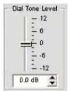
The Dial Tone Level slider allows you to set dial tone gain using the slider or selector box. The default is zero. Range is -12dB to 12dB in 1dB increments.
Recv Boost Slider
The Receive Boost slider allows you to set the gain for the incoming telco/VolP rx signal. This is typically used for low-level telephone lines, allowing the signal to be boosted to an acceptable level of performance. To use Receive Boost, check the Recv Boost check box, then move the slider to the desired gain settings.
Recv Boost adds up to 12dB of gain to the signal (adjustable in 3dB increments from 0dB to 12dB). The default is Off.
Recv Input Meter
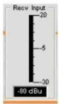
The Receive Input meter displays the dB level of the incoming telco signal prior to any signal processing.
NOTE: All meters in Console are peak-level meters.
NC Button

Clicking the Noise Cancellation button opens the Channel Property Configuration: Telco/VoIP RX window with the NC tab selected, allowing you to configure noise cancellation settings.
To use noise cancellation, click Enable Noise Canceller, then adjust the Cancellation Depth to the setting which provides the best combination of low noise and maximum speech clarity for your installation. The attenuation depth can be set in 1dB increments from 6dB to 15dB. The default is 6dB. The noise canceller default is Off.
ClearEffect™ Button

To reduce bandwidth requirements, telephone lines limit audio bandwidth to a range of 300Hz–3.3kHz. ClearEffect ^™ enhances the incoming signal from a telephone line to emulate wideband audio by adding high and low frequencies to the audio signal.
Click the ClearEffect™ button to toggle this feature on and off. The default is On.
ALC Button

Clicking the Automatic Level Control button toggles ALC on and off. ALC provides auto-leveling for all conference call participants on the telco/VoIP rx line, keeping soft and loud participants at a consistent level. The default is Off. See AGC/ALC for additional information.
NOM Button

Maintains a constant output level by automatically adjusting gain levels based on the number of mics gated on and routed to the selected output channel. NOM reduces the output level proportionally by 3dB for every doubling in the number of open mics. When using NOM over the expansion bus, only I – R Buses support passing NOM information. The default is On.
Mute Button

Clicking the Mute button toggles muting for the telco receive channel. The default is Off.
Gain Slider
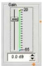
The Gain slider changes the gain for the telco receive channel from nominal 0. To change the value, use the slider or the selector box. Range is from -65 to +20dB in .5dB increments. The default is 0dB.
Min/Max Limits
Use the yellow and green upper and lower limit arrows on the Gain Scale in the Gain section of the screen to set minimum and maximum gain level limits. These limits only apply when using relative gain commands; absolute gain commands can exceed the min and max limits. Min/Max limits apply to all serially connected control devices and prevent users from adjusting levels beyond the specified levels.
Post-Gain Meter
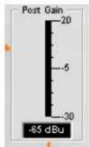
The Post Gain level meter displays the post-gain signal level in dB.
Channel Routing Matrix
The channel routing matrix section of the Channel screen shows the associated matrix row and audio routing configuration for the selected input channel (telco/VolP rx in this case). Clicking a cross point box selects it, clicking it a second time sets the cross point, as indicated by a green box. The dB level for set cross points is shown numerically in the box.

For telco/VoIP rx channels, Outputs 5-8, Speaker, and To Exp. Bus S are selected as cross points by default. You can click directly on any cross point box in the top row to a cross point (routing path), or leave it blank, as required for your installation.
To adjust cross point gain/attenuation, right-click on a cross point box and select Cross Point from the shortcut menu.
The Cross Point Attenuation slider appears. Move the slider or use the selector box to set the gain/attenuation level in dB. The range is from -60 to 12dB in .5dB increments. The default is 0dB.
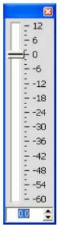
NOTE: Your changes are automatically saved when you close the slider.
In the channel routing matrix, pressing the button underneath an Output, Process, or Fader cross point box displays the signal flow diagram and configuration controls for that output channel as shown below.
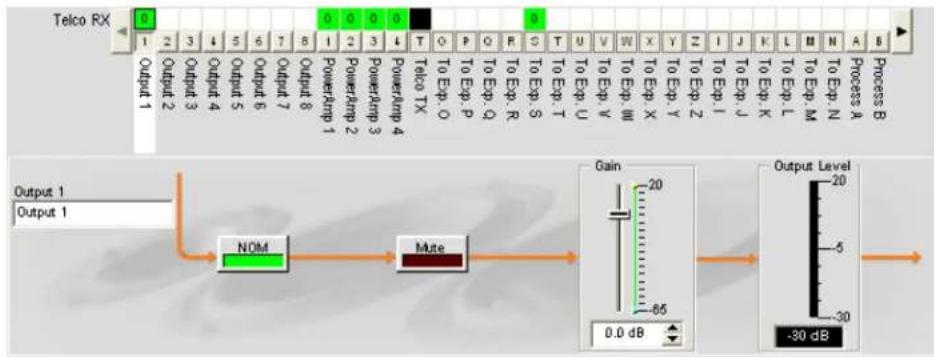
flowchart
graph LR
    A["Output 1"] --> B["NOM"]
    B --> C["Mute"]
    C --> D["Gain"]
    D --> E["Output Level: -30 dB"]
This display is identical to that shown in Channel when the output channel is selected in the Tree View pane. See Output Settings for more information.
You can change the label (name) of the output channel in the Output entry box, toggle the NOM button to turn constant gain mode on or off, toggle the Mute button to mute or un-mute the channel, and use the Gain slider to set the gain level for the channel. The Output Level meter shows the level for the channel in real time.
NOTE: Changes to configuration settings made in the channel routing matrix apply globally to the output, processing, or fader channel. For example, changing the label (name) from "Output 1" to "Ceiling Speakers" changes the name of the channel in the Tree View pane, and everywhere else the label appears in Console.
Creating Channel Objects
One of the most powerful features of Console is the ability to create Channel Objects. Channel objects capture all settings for the channel at the time the object is created. After configuring an input using the Channel tab as described in this topic, you can save it into the Database, and use drag and drop configuration to streamline configuration tasks.
To save a telco/VolP rx channel configuration, right click in the Channel screen (anywhere above the channel routing matrix). From the shortcut menu that appears, select Export Object as shown below.
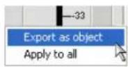
Enter an appropriate Label (name) in the entry field of Export Object dialog as shown below.
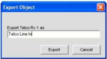
Click Export to save the configuration to the database, or Cancel to return to the Channel screen
Console saves the object to the database and displays it in the Object Tree as shown below.
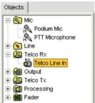
For more information on using audio devices and channel objects, refer to the Table of Contents for these topics:
AV Devices•
Creating AV Devices
Channel Objects•
Database Tab•
Drag & Drop Configuration
Optimizing Input Gain Structure
Optimizing gain structure for input channels maximizes the signal-to-noise ratio for the channel and ensures optimal audio performance. When configuring the telco/VolP rx channel, ClearOne recommends that you follow the procedures outlined in the Optimizing Gain Structure topic.
For more information, refer to the Table of Contents for these related topics:
Channel Tab Overview•
NC (Noise Cancellation)
Mic Gating•
Gating Tab·
AGC/ALC (Automatic Gain Control/Automatic Level Control)
Label Editor•
Output Settings
Telco/VoIP tx Settings •
OUTPUT SETTINGS
Output Settings enable you to customize output channel settings. All settings for a given output are available on the Channel screen.
Accessing Output Settings
With the Channel tab selected on the Tab Bar, select the desired output channel on the Tree View tab in the Site Pane.
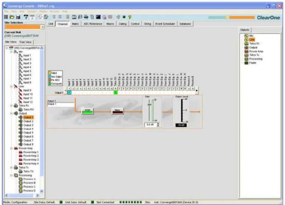
flowchart
graph TD
    A["Input 1"] --> B["Output 1"]
    C["Input 2"] --> D["Output 2"]
    E["Input 3"] --> F["Output 3"]
    G["Input 4"] --> H["Output 4"]
    I["Input 5"] --> J["Output 5"]
    K["Input 6"] --> L["Output 6"]
    M["Input 7"] --> N["Output 7"]
    O["Input 8"] --> P["Output 8"]
    Q["Input 9"] --> R["Output 9"]
    S["Input 10"] --> T["Output 10"]
    U["Input 11"] --> V["Output 11"]
    W["Input 12"] --> X["Output 12"]
    Y["Line"] --> Z["Line Rx"]
    AA["Line"] --> AB["Line Tx"]
    AC["Line"] --> AD["Line Rx"]
    AE["Line"] --> AF["Line Tx"]
    AG["Line"] --> AH["Line Rx"]
    AI["Line"] --> AJ["Line Tx"]
    AK["Line"] --> AL["Line Rx"]
    AM["Line"] --> AN["Line Tx"]
    AO["Line"] --> AP["Line Rx"]
    AQ["Line"] --> AR["Line Tx"]
    AS["Line"] --> AT["Line Rx"]
    AU["Line"] --> AV["Line Tx"]
    AW["Line"] --> AX["Line Rx"]
    AY["Output 1"] --> AZ["NOM"]
    BA["Output 2"] --> BB["Mix"]
    BC["Output 3"] --> BD["NOM"]
    BE["Output 4"] --> BF["Mix"]
    BG["Output 5"] --> BH["NOM"]
    BI["Output 6"] --> BJ["Mix"]
    BK["Output 7"] --> BL["NOM"]
    BM["Output 8"] --> BN["Mix"]
    BO["Output 9"] --> BP["NOM"]
    BZ["Output 10"] --> CA["NOM"]
    CB["Output 11"] --> CC["NOM"]
    DD["Output 12"] --> EE["NOM"]
    BF --> F
    BG --> AG
    BH --> AH
    BI --> AI
    BJ --> AJ
    BB --> AK
    CC --> AL
    CE["Gain"] --> FL
    GA["Output Level"] --> GH
    AI --> GF
    AJ --> GF
    AK --> GF
    AL --> GF
    AM --> GF
    AN --> GF
    AO --> GF
    AP --> GF
    AQ --> GF
    BR --> GF
    CA --> GF
    BL --> GF
    BG --> GF
    BH --> GF
    BI --> GF
    BJ --> GF
    AK --> GF
    AL --> GF
    AM --> GF
    AN --> GF
    AO --> GF
    BR --> GF
    CA --> GF
    AD --> GF
    AE --> GF
    AF --> GF
    BG --> GF
    BH --> GF
    BI --> GF
    BJ --> GF
    AK --> GF
    AL --> GF
    AM --> GF
    AN --> GF
    AO --> GF
    BR --> GF
    CA --> GF
    AD --> GF
    AE --> GF
    AF --> GF
The center pane of the screen displays a signal flow diagram, a real-time Output Level Gain meter, as well as the channel routing matrix, which shows the audio routing configuration for the selected output channel.
The following sections describe how to use output channel configuration controls.
Channel Label
Rename the channel by entering a name in the Label entry field (optional). Label changes are global, and appear throughout Console wherever the label is referenced.
NOM (Number of Open Mics/Constant Level)
Maintains a constant output level by automatically adjusting gain levels based on the number of mics gated on and routed to the selected output channel. NOM reduces the output level proportionally by 3dB for every doubling in the number of open mics. When using NOM over the expansion bus, only I – R Buses support passing NOM information. The default is On.
Mute Button

Clicking the Mute button toggles muting. The default is Off.
Gain Slider
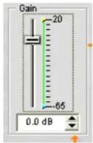
The Gain slider adjusts the output gain level. To change the value, use the slider or selector box. Range is from -65 to +20dB in .5dB increments. The default is 0dB.
Min/Max Limits
Use the yellow and green upper and lower limit arrows on the Gain Scale in the Gain section of the screen to set minimum and maximum gain level limits. These limits only apply when using relative gain commands; absolute gain commands can exceed the min and max limits. Min/Max limits apply to all serially connected control devices and prevent users from adjusting levels beyond the specified levels.
Output Level Meter
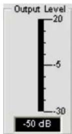
Shows the signal level in dB when a signal is present.
Channel Routing Matrix: Outputs
The channel routing matrix shows the matrix row and audio routing configuration for the selected channel (Output 1 in this case). Clicking a cross point box selects it, clicking it a second time sets the cross point, as indicated by a green box. The dB level for set cross points is shown numerically in the box.

You can click directly on any cross point box in the top row to set a parameter as cross point, or leave it blank, as required for your installation. To adjust cross point gain/attenuation, right-click on a cross point box and select Cross Point from the shortcut menu.
The Cross Point Attenuation slider appears. Move the slider or use the selector box to set the gain/attenuation level in dB. The range is from -60 to 12dB in .5dB increments. The default is 0dB.
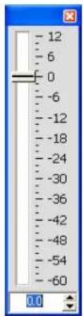
NOTE: Your changes are automatically saved when you close the slider.
Channel Routing Matrix: Inputs, Processing, Faders
In the channel routing matrix, pressing the button above an Input, Process, or Fader cross point box displays the signal flow diagram and configuration controls for that channel.
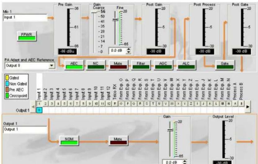
flowchart
graph TD
    A["Pre Gain"] --> B["Gain Coarse"]
    B --> C["Post Gain"]
    C --> D["Post Process"]
    D --> E["Post Gate"]

    subgraph PA Adapt and AEC Reference
        F1["Input 1: PPWR"] --> G1["-86 dBu"]
        G1 --> H1["-30 dB"]
        H1 --> I1["-30 dB"]
        I1 --> J1["-30 dB"]
        J1 --> K1["-30 dB"]
        K1 --> L1["-30 dB"]
        L1 --> M1["-30 dB"]
        M1 --> N1["-30 dB"]
        N1 --> O1["-30 dB"]
        O1 --> P1["-30 dB"]
        P1 --> Q1["-30 dB"]
        Q1 --> R1["-30 dB"]
        R1 --> S1["-30 dB"]
        S1 --> T1["-30 dB"]
        T1 --> U1["-30 dB"]
        U1 --> V1["-30 dB"]
        V1 --> W1["-30 dB"]
        W1 --> X1["-30 dB"]
        X1 --> Y1["-30 dB"]
        Y1 --> Z1["-30 dB"]
        Z1 --> AA1["-30 dB"]
        AA1 --> AB1["-30 dB"]
        AB1 --> AC1["-30 dB"]
    end

    subgraph Output 1
        AD["Input 1: 2 3 4 5 6 7 8 9 10 11 12 13 14 15 16 17 18 19 20 21 22 23 24 25 26 27 28 29 30 31 32 33 34 35 36 37 38 39 40 41 42 43 44 45 46 47 48 49 50 51 52 53 54 55 56 57 58 59 60 61 62 63 64 65 66 67 68 69 70 71 72 73 74 75 76 77 78 79 80 81 82 83 84 85 86 87 88 89 90 91 92 93 94 95 96 97 98 99<br>    end<br>    <br>    subgraph Output Level<br>        AG[Output Level: -20, -5, -30"] --> AH["Output Level: -20, -5, -30"]
    end
This display is identical to that shown in Channel when the channel is selected in the Tree View pane. See Mic Input Settings, Line Input Settings, Processing Settings, and Fader Settings for more information.
You can change the label (name) of the channel in the Output entry box, toggle the NOM button to turn constant gain mode on or off, toggle the Mute button to mute or un-mute the channel, and use the Gain slider to set the gain level for the channel. The Output Level meter shows the level for the channel in real time.
NOTE: Changes to configuration settings made in the channel routing matrix apply globally to that channel. For example, changing the label (name) from "Input 1" to "Ceiling Mic" changes the name of the channel in the Tree View pane, and everywhere else the label appears in Console.
Creating Channel Objects
One of the most powerful features of Console is the ability to create Channel Objects. Channel objects capture all settings for the channel at the time the object is created. After configuring an input using the Channel tab as described in this topic, you can save it into the Database, and use drag and drop configuration to streamline configuration tasks.
To save an input channel configuration, right click in the Channel screen (anywhere above the channel routing matrix). From the shortcut menu that appears, select Export Object as shown below.
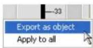
NOTE: You can apply the channel configurations for the current channel to all channels of the same type by selecting the Apply to all option. Use this option with caution because there is no way to undo the changes.
Enter an appropriate Label (name) in the entry field of Export Object dialog as shown below.
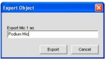
Click Export to save the configuration to the database, or Cancel to return to the Channel screen.
Console saves the object to the database and displays it in the Object Tree as shown below.
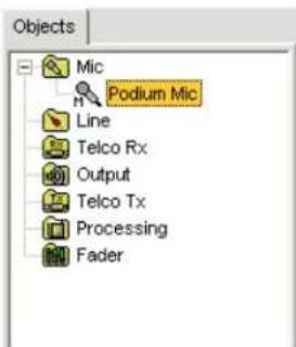
For more information on using audio devices and channel objects, see the Table of Contents for the following topics:
AV Devices•
Creating AV Devices•
Channel Objects
Database Tab•
Drag & Drop Configuration
TELCO/VOIP TX SETTINGS
Telco/VoIP Tx Settings enable you to customize telephone transmit channel settings using the Channel screen.
Accessing Telco/VoIP Tx Settings
With the Channel tab selected on the Tab Bar, select the Telco/VoIP Tx channel on the Tree View tab in the Site Pane.
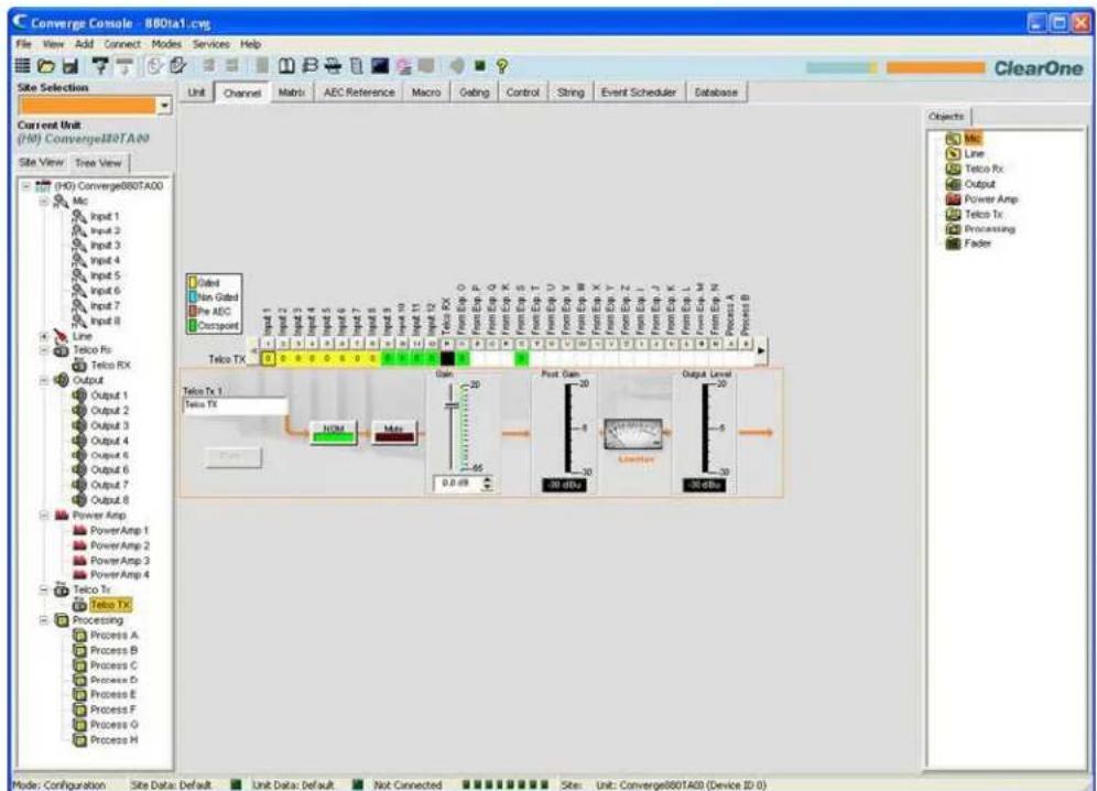
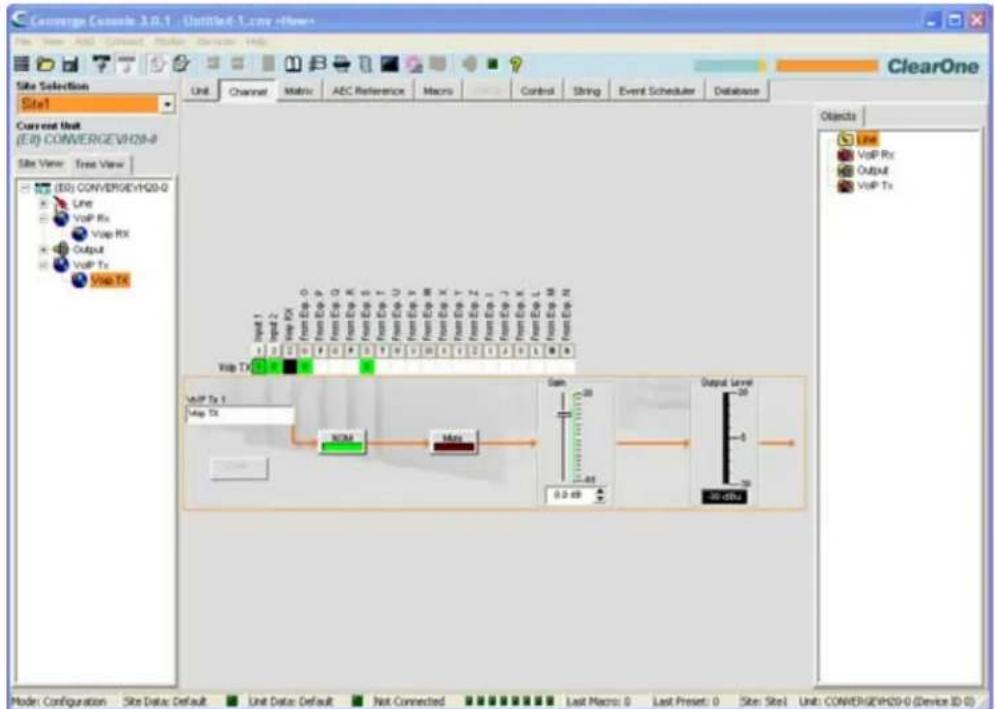
As shown above, the Center Pane displays a signal flow diagram for the telco/VoIP tx channel, real-time peak-level meters, as well as the channel routing matrix, which shows the audio routing configuration for the channel. Configuration settings for the telco/VoIP tx channel are displayed as controls (buttons, sliders, etc.) which are located at the appropriate stage in the signal flow.
The following sections describe how to use these controls to configure telco transmit settings for your installation.
Channel Label
Rename the channel by entering a name in the Label entry field (optional). Label changes are global, and appear throughout Console wherever the label is referenced.
Dialer Button
The Dialer button opens the telephone dialer (shown below), allowing you to place calls to establish a conference call with a remote location.
![C Slater MUTE MUTE RE_NULL 2/12/2007 1:07:17 PM [143x] PhoneBook ClearOne GHI JKL MNO ON/OFF REDIAL FLASH 7 PUN5 TUV WOYZ * 0 # PHONEBOOK. Close](/content/2026/05/777819/images/961bb9d04756d8cfbebc63fecaeb6b085ab5db7818905f720f123af3416ab5ff.jpg)
See Dialer for more information on using the dialer and its features.
NOM (Number of Open Mics/Constant Level)

Maintains a constant output level by automatically adjusting gain levels based on the number of mics gated on and routed to the selected output channel. NOM reduces the output level proportionally by 3dB for every doubling in the number of open mics. When using NOM over the expansion bus, only I – R Buses support passing NOM information. The default is On.
Mute Button

Clicking the Mute button toggles muting. The default is Off.
Gain Slider
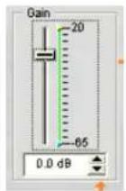
The Gain slider adjusts the output gain level. To change the value, use the slider or selector box. Range is from -65 to +20dB in .5dB increments. The default is 0dB.
Min/Max Limits
Use the yellow and green upper and lower limit arrows on the Gain Scale in the Gain section of the screen to set minimum and maximum gain level limits. These limits only apply when using relative gain commands; absolute gain commands can exceed the min and max limits. Min/Max limits apply to all serially connected control devices and prevent users from adjusting levels beyond the min/max levels.
Post-Gain Meter
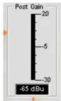
The Post Gain level meter displays the post-gain signal level in dB.
Limiter
The Limiter limits the output level to the telco side to comply with telco system requirements. Note that the meter is only a graphic; it does not show limiter activity. (Not used in VoIP settings)
Output Level Meter
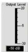
Shows the signal level in dB when a signal is present.
Channel Routing Matrix: Telco/VoIP TX
The graphic below shows the Telco/VoIP tx channel routing matrix.

All inputs from Exp. O, and from Exp. S are selected as cross points and the first four inputs are gated by default. Clicking a cross point box selects it, clicking it a second time sets the cross point, as indicated by a colored box. The dB level for set cross points is shown numerically in the box.
To adjust cross point gain/attenuation, right-click on a cross point box and select Cross Point from the shortcut menu.
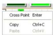
The Cross Point Attenuation slider appears. Move the slider or use the selector box to set the gain/attenuation level in dB. The range is from -60 to 12dB in .5dB increments. The default is 0dB.
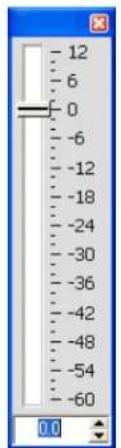
NOTE: Your changes are automatically saved when you close the slider.
Channel Routing Matrix: Inputs, Processing, Faders
In the channel routing matrix, pressing the button above an Input, Process, or Fader cross point box displays the signal flow diagram and configuration controls for the channel as shown below.
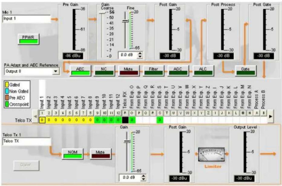
flowchart
graph TD
    A["Pre Gain"] --> B["Gain Coarse"]
    B --> C["Post Gain"]
    C --> D["Post Process"]
    D --> E["Post Gate"]

    subgraph PA Adapt and AEC Reference
        F["Input 1: Mio 1 Input 1"] --> G["PPWR"]
        H["PA Adapt and AEC Reference Output 8"] --> I["AEC"]
        J["Output 8: AEC"] --> K["NC"]
        L["Output 8: Mate"] --> M["Filter"]
        N["Output 8: AGC"] --> O["ALC"]
        P["Output 8: Gate"] --> Q["Gate"]
    end

    subgraph Telco TX
        R["Input 1: Gated"]
        S["Input 2: Non Gated"]
        T["Input 3: Pre AEC"]
        U["Input 4: Crosspoint"]
        V["Input 5: Gated"]
        W["Input 6: Non Gated"]
        X["Input 7: Pre AEC"]
        Y["Input 8: Crosspoint"]
        Z["Input 9: Gated"]
        AA["Input 10: Non Gated"]
        AB["Input 11: Pre AEC"]
        AC["Input 12: Crosspoint"]
        AD["Input 13: Gated"]
        AE["Input 14: Non Gated"]
        AF["Input 15: Pre AEC"]
        AG["Input 16: Crosspoint"]
        AH["Input 17: Gated"]
        AI["Input 18: Non Gated"]
        AJ["Input 19: Pre AEC"]
        AK["Input 20: Crosspoint"]
    end

    subgraph Output Level
        AL["Output Level -30 dBu"] --> AM["Limiter"]
    end

    %% Legend
    %% Legend
    %% Legend
This display is identical to that shown in Channel when the channel is selected in the Tree View pane. See Mic Input Settings, Line Input Settings, Processing Settings, and Fader Settings for more information.
You can change the label (name) of the channel in the Telco/VolP tx entry box, toggle the NOM button to turn constant gain mode on or off, toggle the Mute button to mute or un-mute the channel, and use the Gain slider to set the gain level for the channel. The Output Level meter shows the level for the channel in real time.
NOTE: Changes to channel configuration settings made in the channel routing matrix apply globally to that channel. For example, changing the label (name) from "Input 1" to "Podium Mic" in the Mic 1 entry box changes the name of the channel in the Tree View pane, and everywhere else the label appears in Console.
Creating Channel Objects
One of the most powerful features of Console is the ability to create Channel Objects. Channel objects capture all settings for the channel at the time the object is created. After configuring an input using the Channel tab as described in this topic, you can save it into the Database, and use drag and drop configuration to streamline configuration tasks.
To save an input channel configuration, right click in the Channel screen (anywhere above the channel routing matrix). From the menu that appears, select Export Object as shown below.
NOTE: You can apply the channel configurations for the current channel to all channels of the same type by selecting the Apply to all option. Use this option with caution because there is no way to undo the changes.
Enter an appropriate Label (name) in the entry field of Export Object dialog as shown below.
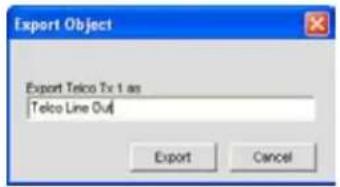
Click Export to save the configuration to the database, or Cancel to return to the Channel screen.
Console saves the object to the database and displays it in the Object Tree as shown below.
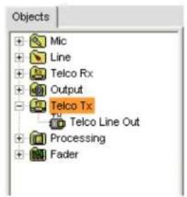
For more information on using audio devices and channel objects, see the following topics:
AV Devices•
Creating AV Devices•
Channel Objects
Database Tab•
Drag & Drop Configuration
Optimizing Output Gain Structure
Optimizing gain structure for output channels ensures optimal audio performance. When initially configuring output channels, ClearOne recommends that you follow the procedures outlined in the Optimizing Gain Structure topic.
For more information, refer to the Table of Contents for these related topics:
Channel Tab Overview•
Mic Gating•
Gating Tab•
Line Input Settings•
Mic Input Settings•
Processing Settings
Fader Settings•
Telco/VolP rx Settings •
Optimizing Gain Structure•
PROCESSING SETTINGS
Processing Settings enable you to configure filters, delay, compression, and gain to create precise audio configurations for any venue. There are four processing blocks available for the 840T (A-D), and eight for the 880, 880T, 880TA, 8i, SR 1212 (A-H) and SR 1212A (A-H).
Accessing Processing Settings
With the Channel tab selected on the Tab Bar, select the desired processing block on the Tree View tab in the Site Pane.
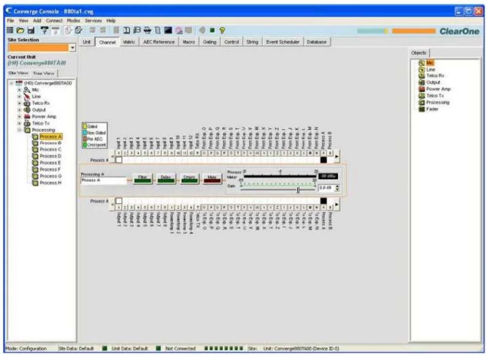
The center pane displays a signal processing diagram, meters, and configuration controls for selected processing block as shown above.
The meters and configuration controls for processing blocks are explained in the following sections.
Channel Label
Rename the channel by entering a name in the Label entry field (optional). Label changes are global, and appear throughout Console wherever the label is referenced.
Filter Button

Pressing the Filter button brings up the Channel Property Configuration window with the Filter Tab selected as shown below.
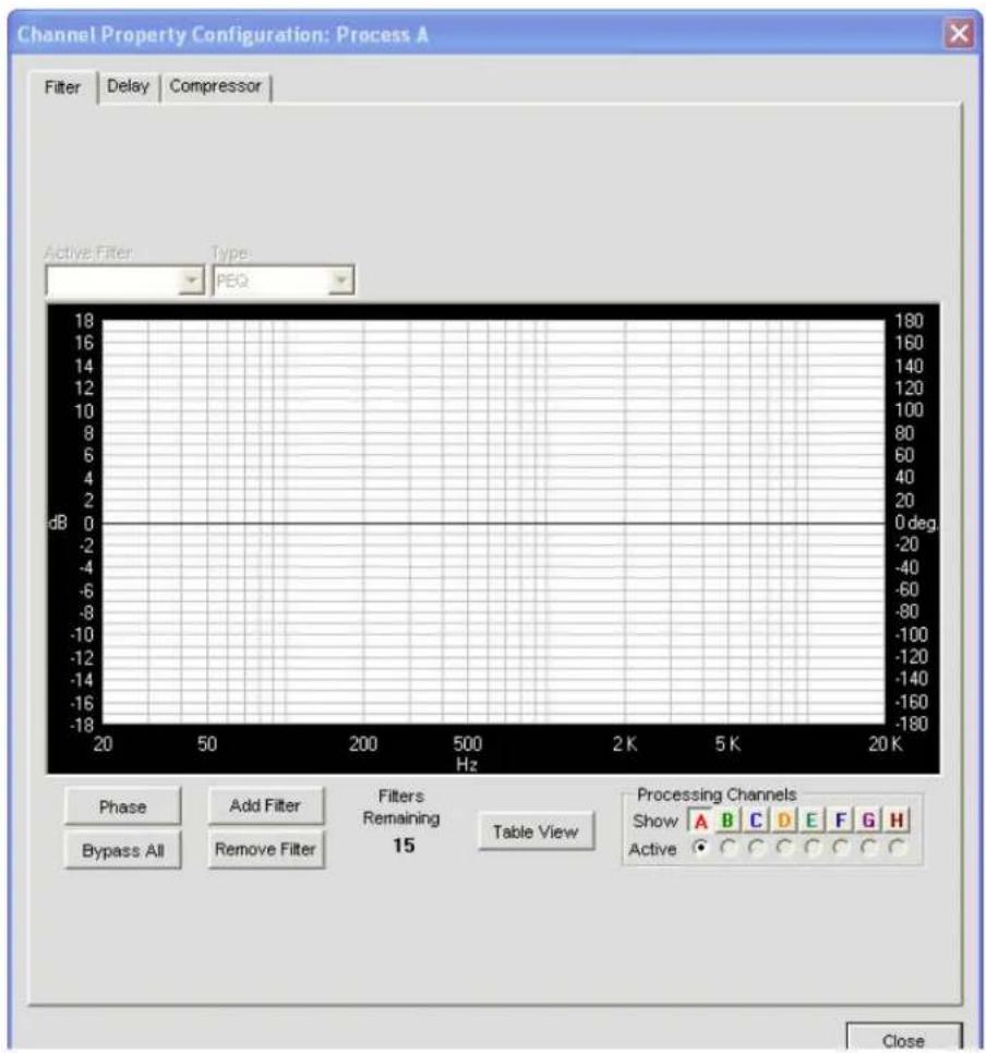
For more information on Filters and their configuration, use the Table of Contents to locate the Filters topic.
Delay Button

Press the Delay button to bring up the Channel Property Configuration window with the Delay Tab selected as shown below.
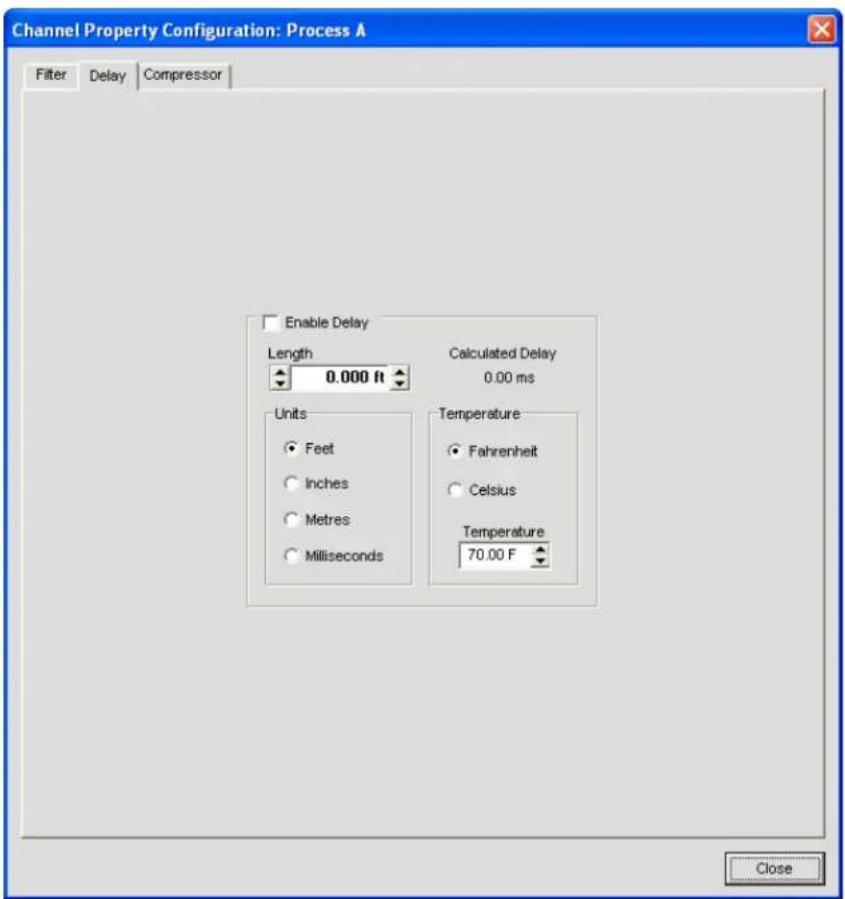
Introducing an appropriate amount of delay to the forward-mounted driver(s) re-establishes the acoustical alignment necessary for proper sound imaging in a room. The same principle of introducing delay applies to separate speaker enclosures located various distances from the listening area.
Other types of delay to consider when establishing delay parameters are delays which occur naturally as a result of processing within the unit. Propagation delay is an example. This delay is caused by operations such as the conversion of the signal between analog and digital formats.
Select the Enable Delay checkbox to enable it. Calibrate the amount of delay using the Length and Temperature configuration controls. Length is defined as the distance between the source and audience. The Calculated Delay reading reflects any changes you make in the Distance and Temperature fields.
Click Close to save changes and return to the Process/Channel window.
Cmprs (Compression) Button
Pressing the Cmprs button opens the Channel Property Configuration window with the Compressor tab selected as shown below.
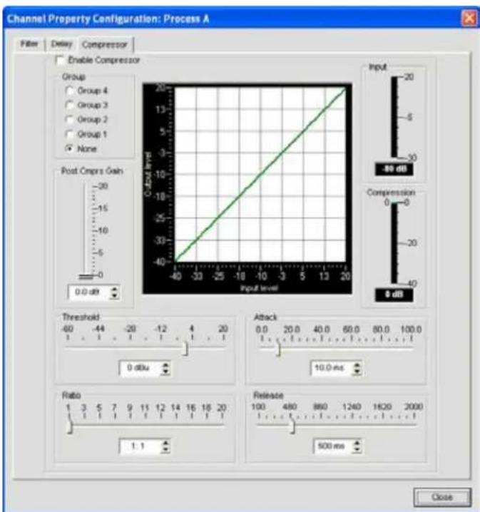
Select the Enable Compressor checkbox to activate the compressor. Using the compressor, you can change the gain transfer characteristics of the signal path and control the dynamics of a signal. Compressor settings are described below.
Group
Use the Group radio buttons to assign this compressor to a compressor group. The default is None. When you assign a compressor to a compressor group—such as a group of two compressors configured for left and right stereo channels—the compressors will monitor each other. When one channel compresses, all compressors in the group compress together.
A compressor group must be configured for a single unit; a group cannot control compressors from multiple units.
Post Compressor Gain
Adjust the compressor gain with the slider or by using the Up/Down arrow buttons. The graph reflects the input/output decibel levels with the gain, ratio, and threshold settings you select.
Threshold
Determines the RMS level at which the compressor begins to operate. The range is from -30 to +20dBu. The default is 0dBu.
Ratio
Changes the rate of compression applied to the input signal as the signal exceeds the threshold level. The range is 1:1 to 1:20dB. The default is 1:1.
Attack
Sets the time increment used to reduce the signal from input level to the prescribed output level when the threshold is exceeded. The range is 0 to 100ms in .5ms steps. The default is 10ms.
Release
Sets the time increment used to restore the signal to the input level when the signal drops below the threshold. The range is 100ms to 2 seconds, in 5ms increments. The default is 500ms.
Input Meter
Shows the level of the signal as it enters the compressor.
Compression Meter
Shows the instantaneous compression value at a given time.
Gain Slider & Process Meter
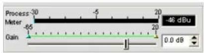
Use the Gain Slider to establish the gain level for this processing channel. Range is -65 to 20dB. The Process Meter shows the signal level when a signal is present.
Min/Max Limits
Use the yellow and green upper and lower limit arrows on the Gain Scale to set minimum and maximum gain level limits. These limits only apply when using relative gain commands; absolute gain commands can exceed the min and max limits. Min/Max limits apply to all serially connected control devices and prevent users from adjusting levels beyond the min/max levels, provided relative gain commands are used.
Channel Routing Matrix
The channel routing matrix shows the Matrix row and audio routing configuration for the selected channel (Process A in this case). Clicking a cross point box selects it, clicking it a second time sets the cross point, as indicated by a colored box. The dB level for set cross points is shown numerically in the box.
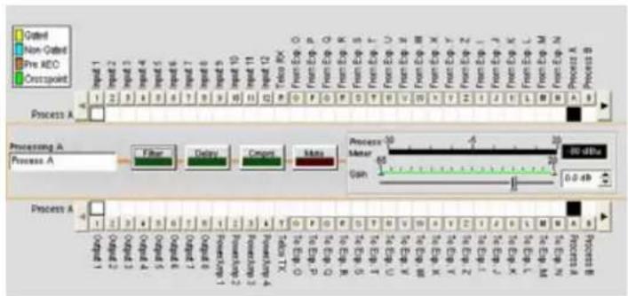
You can click directly on any cross point box to set a cross point, or leave it blank, as required for your installation. To adjust cross point gain/attenuation, right-click on a cross point box and select Cross Point from the shortcut menu.
The Cross Point Attenuation slider appears as shown below. Move the slider or use the selector box to set the gain/attenuation level in dB. The range is from -60 to 12dB in .5dB increments. The default is 0dB.
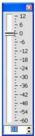
NOTE: Your changes are automatically saved when you close the slider.
Expanded Channel Routing Matrix
In the channel routing matrix, pressing the button above or below the cross point box for a channel displays the signal flow diagram and configuration controls for that channel as shown below.
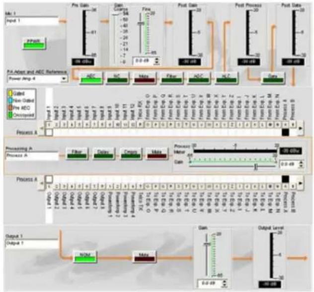
flowchart
Medical procedure flowchart for patient management and REC reference, covering pre-Gain, Post-Gain, Post-Process, and Post-Date stages with associated diagnostic indicators.This display is identical to that shown in Channel when the channel is selected in the Tree View pane.
You can change the label (name) of the channel in the label entry box. You can also change channel configuration settings. For example, for an output channel you can toggle the NOM button to turn constant gain mode on or off, toggle the Mute button, and use the Gain slider to set the gain level for the channel.
NOTE: Changes to configuration settings made in the channel routing matrix apply globally to that channel. For example, changing the label (name) from "Input 1" to "Podium Mic" changes the name of the channel in the Tree View pane, and everywhere else the label appears in Console.
Creating Channel Objects
One of the most powerful features of Console is the ability to create Channel Objects. Channel objects capture all settings for the channel at the time the object is created. After configuring a processing channel using the Channel tab as described in this topic, you can save it into the Database, and use drag and drop configuration to streamline configuration tasks.
To save a processing channel configuration, right click in the processing section of the screen (surrounded by an orange rectangle). From the menu that appears, select Export Object as shown below.
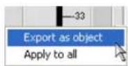
NOTE: You can apply the channel configurations for the current channel to all channels of the same type by selecting the Apply to all option. Use this option with caution because there is no way to undo the changes.
Enter an appropriate Label (name) in the entry field of Export Object dialog as shown below.
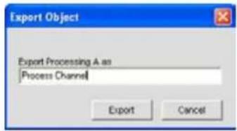
Click Export to save the configuration to the database, or Cancel to return to the Channel screen.
Console saves the object to the database and displays it in the Object Tree as shown below.
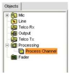
For more information on using AV devices and channel objects, see the following topics:
AV Devices•
Creating AV Devices•
Channel Objects
Database Tab•
Drag & Drop Configuration
For more information, refer to the Table of Contents for these related topics:
Channel Tab Overview
Filters•
Line Input Settings•
Mic Input Settings•
Output Settings•
Processing Settings•
Fader Settings•
Telco/VoIP rx Settings •
Telco/VoIP tx Settings •
Drag & Drop Configuration
FADER SETTINGS
NOTE: The Converge Pro 880TA and Converge SR 1212A do not have fader settings.
Fader Settings allow you to set configuration parameters for fader channels using the Channel tab. Fader channels are internal sub-bus channels similar to Processing channels that provide additional sub-bus mixes to control volume settings within a site.
Accessing Fader Settings
With the Channel tab selected on the Tab Bar, select the desired fader channel on the Tree View tab in the Site Pane.
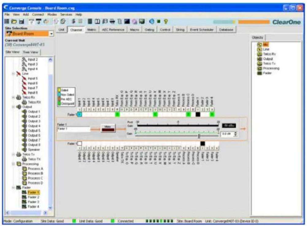
As shown above, the Center Pane displays the configuration controls and gating for the selected Fader channel. Fader configuration controls are described in the following sections.
Channel Label
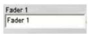
Rename the channel by entering a name in the Label entry field (optional). Label changes are global, and appear throughout Console wherever the label is referenced.
Mute Button
Clicking the Mute button toggles muting. The default is Off.
Gain Slider & Post Gain Meter

Adjusts output gain level. Use the Gain slider to adjust output volume level. You can also enter the level directly in the selector box. The Post Gain meter reflects the post-gain level of the signal in dB.
Min/Max Limits
Use the yellow and green upper and lower limit arrows on the Gain scale to create minimum and maximum gain level limits. These limits only apply when using relative gain commands; absolute gain commands can exceed the min and max limits. Min/Max limits apply to all serially connected control devices and prevent users from adjusting levels beyond the min/max levels.
Channel Routing Matrix: Faders
The channel routing matrix shows the Matrix row and audio routing configuration for the selected channel (Fader 1 in this case). Clicking a cross point box selects it, clicking it a second time sets the cross point, as indicated by a green box. The dB level for set cross points is shown numerically in the box

You can click directly on any cross point box to set a cross point, or leave it blank, as required for your installation.
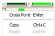
To adjust cross point gain/attenuation, right-click on a cross point box and select Cross Point from the shortcut menu.
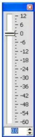
The Cross Point Attenuation slider appears. Move the slider or use the selector box to set the gain/attenuation level in dB. The range is from -60 to 12dB in .5dB increments. The default is 0dB.
NOTE: Your changes are automatically saved when you close the slider. Expanded Channel Routing Matrix
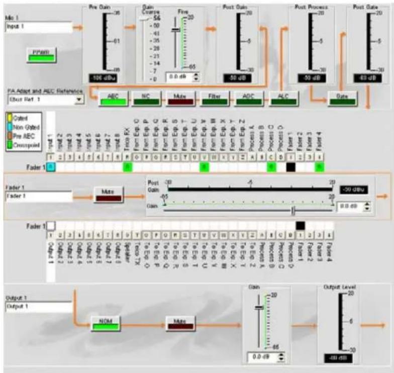
flowchart
graph TD
    A["Input 1: Pre Gain"] --> B["Gain Coarse"]
    B --> C["Fire"]
    C --> D["Post Gain"]
    D --> E["Post Process"]
    E --> F["Post Gate"]

    subgraph Input_1
        G["PPM1"]
        H["PA Adapt and AEC Reference"]
        I["Error Ref. 1"]
    end

    subgraph Output_1
        J["Faster 1: Input 2, Input 3, Input 4, Input 5, Input 6, Input 7, Input 8"]
        K["Faster 1: Faster 2, Faster 3, Faster 4"]
    end

    L["Pre Gain"] --> M["Gain Coarse"]
    M --> N["Fire"]
    N --> O["Post Gain"]
    O --> P["Post Process"]
    P --> Q["Post Gate"]

    R["PCDC"] --> S["NOM"]
    T["Non Gated"] --> U["Mate"]
    V["Pre AEC"] --> W["Filter"]
    X["Crosspiled"] --> Y["ADC"]
    Z["Data"] --> AA["0.0 dB"]

    AB["Input 1: ABC"] --> AC["NC"]
    AD["Input 2: Non Gated"] --> AE["FC"]
    AF["Input 3: Pre AEC"] --> AG["FC"]
    AH["Input 4: Crosspiled"] --> AI["FC"]
    AJ["Input 5: Pre AEC"] --> AK["FC"]
    AL["Input 6: Pre AEC"] --> AM["FC"]
    AN["Input 7: Pre AEC"] --> AO["FC"]
    AP["Input 8: Pre AEC"] --> AQ["FC"]
    AR["Input 9: Pre AEC"] --> AS["FC"]
    AT["Input 10: Pre AEC"] --> AU["FC"]
    AV["Input 11: Pre AEC"] --> AW["FC"]
    AX["Input 12: Pre AEC"] --> AY["FC"]
    AZ["Input 13: Pre AEC"] --> BA["FC"]
    BB["Input 14: Pre AEC"] --> BC["FC"]
    BD["Input 15: Pre AEC"] --> BE["FC"]
    BF["Input 16: Pre AEC"] --> BG["FC"]
    BH["Input 17: Pre AEC"] --> BI["FC"]
    BJ["Input 18: Pre AEC"] --> BK["FC"]
    BL["Input 19: Pre AEC"] --> BLA["FC"]
    BM["Faster 1: Input 2, Input 3, Input 4, Input 5, Input 6, Input 7, Input 8"] --> BN["Tone RX"]
        BO["Faster 2: Non Gated"] --> BP["Faster 3: Pre AEC"]
        BQ["Faster 4: Crosspiled"] --> BR["Faster 5: Pre AEC"]
        BS["Faster 6: Pre AEC"] --> BT["Faster 7: Pre AEC"]
        BU["Faster 7: Pre AEC"] --> BV["Faster 8: Pre AEC"]
        BW["Faster 8: Pre AEC"] --> BX["Faster 9: Pre AEC"]
        BY["Faster 9: Pre AEC"] --> BZ["Faster 10: Pre AEC"]
        CA["Faster 10: Pre AEC"] --> CB["Faster 11: Pre AEC"]
        CC["Faster 11: Pre AEC"] --> CD["Faster 12: Pre AEC"]
        DE["Faster 12: Pre AEC"] --> DF["Faster 13: Pre AEC"]
        DG["Faster 13: Pre AEC"] --> DH["Faster 14: Pre AEC"]
        DI["Faster 14: Pre AEC"] --> DJ["Faster 15: Pre AEC"]
        DK["Faster 15: Pre AEC"] --> DL["Faster 16: Pre AEC"]
        DN["Faster 16: Pre AEC"] --> DE
        DO["Faster 16: Pre AEC"] --> DP["Faster 17: Pre AEC"]
        DPF["Faster 17: Pre AEC"] --> DR["Faster 18: Pre AEC"]
        DS["Faster 18: Pre AEC"] --> DT["Faster 19: Pre AEC"]
        DU["Faster 19: Pre AEC"] --> DV["Faster 20: Pre AEC"]
        DW["Faster 20: Pre AEC"] --> DX["Faster 21: Pre AEC"]
        DXF["Faster 21: Pre AEC"] --> DBF["Faster 22: Pre AEC"]
        DBF --> DCF["Faster 23: Pre AEC"]
        DD["Faster 23: Pre AEC"] --> DE
        DEF["Faster 24: Pre AEC"] --> DEF["Faster 25: Pre AEC"]
        DEG["Faster 25: Pre AEC"] --> DEH["Faster 26: Pre AEC"]
        DEI["Faster 26: Pre AEC"] --> DEJ["Faster 27: Pre AEC"]
        DEK["Faster 27: Pre AEC"] --> DEL["Faster 28: Pre AEC"]
        DEM["Faster 28: Pre AEC"] --> DEN["Faster 29: Pre AEC"]
        DEO["Faster 29: Pre AEC"] --> DEP["Faster 30: Pre AEC"]
        DEQ["Faster 30: Pre AEC"] --> DER["Faster 31: Pre AEC"]
        DES["Faster 31: Pre AEC"] --> DET["Faster 32: Pre AEC"]
        DEU["Faster 32: Pre AEC"] --> DEU
        DEV["Faster 32: Pre AEC"] --> DEV
        DEW["Faster 32: Pre AEC"] --> DEW
        DEX["Faster 32: Pre AEC"] --> DEX
        DEY["Faster 32: Pre AEC"] --> DEY
        DEZ["Faster 32: Pre AEC"] --> DEZ
        DEYF["Faster 32: Pre AEC"] --> DEYF
        DEYG["Faster 32: Pre AEC"] --> DEYG
        DEYZ["Faster 32: Pre AEC"] --> DEYZ
        DEYZF["Faster 32: Pre AEC"] --> DEYZF
        DEYZG["Faster 32: Pre AEC"] --> DEYZG
        DEYZH["Faster 32: Pre AEC"] --> DEYZH
        DEYZI["GAIN -30/66 dB"] --> DZE["GAIN -66 dB"]
    end

    style Input_1 fill:#f9f,stroke:#333
    style Output_1 fill:#ccf,stroke:#333
This display is identical to that shown on the Channel tab when the channel is selected in the Tree View pane.
You can change the label (name) of the channel in the label entry box. You can also change channel configuration settings. For example, for an output channel you can toggle the NOM button to turn constant gain mode on or off, toggle the Mute button, and use the Gain slider to set the gain level for the channel.
NOTE: Changes to channel configuration settings made in the channel routing matrix apply globally to that channel. For example, changing the label (name) from "Output 1" to "Ceiling Speakers" changes the name of the channel in the Tree View pane, and everywhere else the label appears in Console.
Creating Channel Objects
One of the most powerful features of Console is the ability to create Channel Objects. Channel objects capture all settings for the channel at the time the object is created. After configuring a fader channel using the Channel tab as described in this topic, you can save it into the Database, and use drag and drop configuration to streamline configuration tasks.
To save a fader channel configuration, right click in the fader section of the screen (surrounded by an orange rectangle). From the menu that appears, select Export Object as shown below.
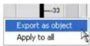
NOTE: You can apply the channel configurations for the current channel to all channels of the same type by selecting the Apply to all option. Use this option with caution because there is no way to undo the changes.
Enter an appropriate Label (name) in the entry field of Export Object dialog as shown below.
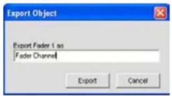
Click Export to save the configuration to the database, or Cancel to return to the Channel screen.
Console saves the object to the database and displays it in the Object Tree as shown below.
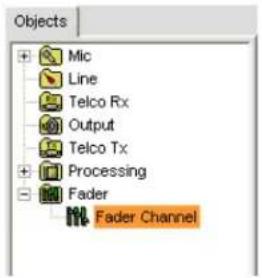
For more information on using AV devices and channel objects, see the following topics:
AV Devices•
Creating AV Devices•
Channel Objects•
Database Tab·
Drag & Drop Configuration
For more information, refer to the Table of Contents for these related topics:
Channel Tab Overview
Filters•
Line Input Settings•
Mic Input Settings•
Output Settings•
Processing Settings•
Fader Settings•
Telco/VoIP rx Settings •
Telco/VoIP tx Settings •
Drag & Drop Configuration
MATRIX TAB
The Matrix Tab is used to route audio to one or more destinations (outputs, expansion bus, processing, or fader channels) and to create cross points between channels.
Accessing the Matrix
To access the matrix, select the Matrix Tab from the Tab Bar in Console.
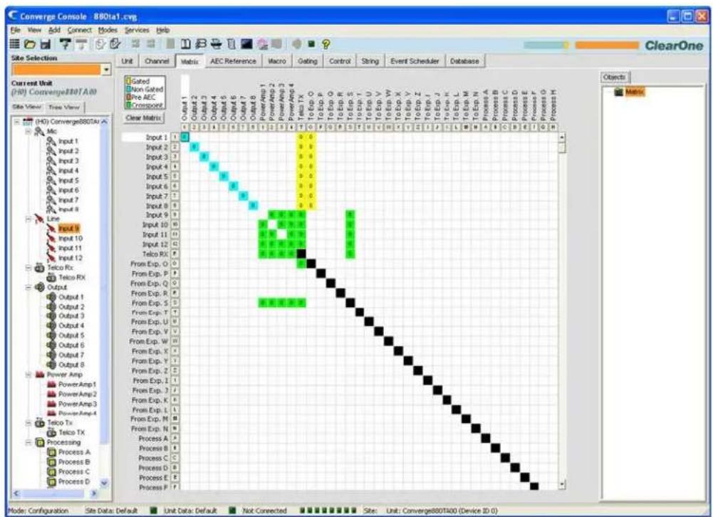
The matrix appears with the current routing configuration displayed for all channels. The functionality of the matrix screen is described in the following sections.
Routing Legend
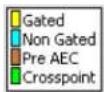
The routing legend shows the status of cross points using colored cells that mark the intersection or cross point of the routing from input to output. The color of the cross point cell identifies the input type:
• Yellow = gated mic input
• Blue = non-gated mic input
- Brown = pre-AEC
- Green = cross point
NOTE: The current audio level to the nearest dB is shown in cross point cells.
Black cell are restricted routing paths which prevent Telco, E-Bus, Processing, and Fader channels from being routed back to themselves.
Clear Matrix Button
Clear Matrix
Press the Clear Matrix button to clear ALL current matrix settings. A Confirm dialog appears asking you to confirm the clear matrix operation. Use caution when using this feature because the operation cannot be undone.
Audio Routing Matrix

heatmap
| Input | Output | Process Type | |---|---|---| | Input 1 | 0 | Process A | | Input 2 | 0 | Process B | | Input 3 | 0 | Process C | | Input 4 | 0 | Process D | | Input 5 | 0 | Process E | | Input 6 | 0 | Process F | | Input 7 | 0 | Process G | | Input 8 | 0 | Process H | | Input 9 | 0 | Process I | | Input 10 | 0 | Process J | | Input 11 | 0 | Process K | | Input 12 | 0 | Process L | | Take RX | 0 | Process M | | From Exp. O | 0 | Process N | | From Exp. P | 0 | Process O | | From Exp. Q | 0 | Process P | | From Exp. R | 0 | Process Q | | From Exp. S | 0 | Process R | | From Exp. T | 0 | Process S | | From Exp. U | 0 | Process T | | From Exp. V | 0 | Process V | | From Exp. W | 0 | Process W | | From Exp. X | 0 | Process X | | From Exp. Y | 0 | Process Y | | From Exp. Z | 0 | Process Z | | From Exp. T | 0 | Process T | | From Exp. U | 0 | Process U | | From Exp. V | 0 | Process V | | From Exp. W | 0 | Process W | | From Exp. X | 0 | Process X | | From Exp. Y | 0 | Process Y | | From Exp. Z | 0 | Process Z | | From Exp. T | 0 | Process T | | From Exp. U | 0 | Process U | | From Exp. V | 0 | Process V | | From Comp. X | 0 | Process X | | From Comp. Y | 0 | Process Y | | From Comp. Z | 0 | Process Z | | From Comp. T | 0 | Process T | | From Comp. U | 0 | Process U | | From Comp. V | 0 | Process V | | From Comp. W | 0 | Process X | | From Comp. X | 0 | Process Y | | From Comp. Y | 0 | Process Z | | From Comp. Z | 0 | Process T | | From Comp. T -1 | 0 | Process U | | From Comp. T -2 | 0 | Process U | | From Comp. T -3 | 0 | Process U | | From Comp. T -4 | 0 | Process U | | From Comp. T -5 | 0 | Process U | | From Comp. T -6 | 0 | Process U | | From Comp. T -7 | 0 | Process U | | From Comp. T -8 | 0 | Process U | | From Comp. T -9 | 0 | Process U | | From Comp. T -10 | 0 | Process U | | From Comp. T -11 | 0 | Process U | | From Comp. T -12 | 0 | Process U | The chart displays a heatmap of values across the grid, with each cell representing a value at that specific input or output point. The color scale indicates the value from left to right.The numbers and letters along the top and left side of the matrix show the cross point coordinates. The Labels for each channel are also shown to make them easy to identify. As you move the cursor over the matrix, the labels for the channels are highlighted in white for each cross point.
NOTE: Clicking on a channel label opens the Channel screen for that channel, allowing you to modify the channel label and change channel configuration settings as needed.
Input Routing
To route an input to an output, click in the routing matrix at the intersection between the input and the output. A mic input can be designated as gated (yellow), non-gated (blue), or pre-AEC (brown) by clicking repeatedly in the cross point. All other input cross points will be colored green.
Expansion Bus I-Z Routing
Audio from any unit on the E-bus network can be placed on the bus or taken off the bus and routed to any destination within the unit.
All models have 18 digital mix-minus buses:
- S-Z Buses: These eight audio buses are line input mixer buses. They are used to route auxiliary audio, such as from a CD player or VCR, to and from other units on the network. These buses are also used as mic mixer buses when NOM count is not required.
- I-R Buses: These ten audio buses are generally used for routing microphone audio between Converge/Converge Pro devices. Information about the number of gated microphones (NOM count) and other relevant information for the microphone mixers are tracked for microphones routed to these buses. By default, all microphones are routed to the O bus.
Process A-D (840T) and Process A-H (880, 880T, 880TA, 8i, SR 1212, SR 1212A) Routing
There are four processing channels on the Converge Pro 840T, eight on the 880, 880T, 880TA, 8i, and eight on
the Converge SR 1212 and SR 1212A. Processing channels enable you to apply filters, compression, delay, and other processing settings to an input or a group of inputs, which can then be routed to a single output or group of outputs.
Cross Point Shortcut Menu
In addition to setting levels, the Cross Point Shortcut Menu (shown below) enables you to copy and paste the configuration of the current cross point to other cross points. To access the shortcut menu, right-click anywhere in the Center Pane of the Matrix screen.
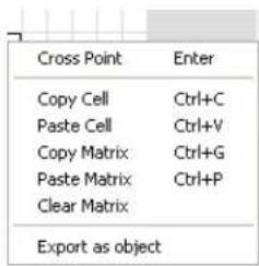
Cross Point Level Control
To adjust the level for a cross point, right-click on the cross point and select Cross Point from the shortcut menu. The Cross Point Attenuation slider appears. Move the slider or use the selector box to set the gain/attenuation level in dB. The range is from -60 to 12dB in .5dB increments. The default is 0dB.
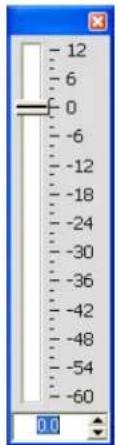
NOTE: Your changes are automatically saved when you close the slider.
The level you select now appears numerically in the cross point box within the matrix.
Copy and Paste Cells
You can copy a single cell or the entire matrix using the shortcut menu options.
To copy a cross point to multiple cross points, press
Copy and Paste Matrix
To copy the entire matrix, use the shortcut menu commands; or press
Clear Matrix
Press the Clear Matrix button to clear all current matrix settings. A Confirm dialog appears asking you to confirm the operation. Use this option with caution because the operation cannot be undone.
Exporting Matrix Objects
Matrix objects allow you to save customized matrix configurations into the Database and reuse them. This enables you to instantly re-configure the entire matrix to accommodate changes in conferencing or venue configuration requirements, and to rapidly configure additional units using drag and drop configuration.
To capture the current matrix configuration and save it as a matrix object, right click anywhere in the center pane of the matrix screen and select Export as object from the shortcut menu.
To apply a matrix object, drag it from the Objects Pane and drop it onto the matrix in the Matrix Tab screen.
For more information on using AV devices and objects, refer to the Table of Contents for these related topics:
Controls and Connections•
Channel Tab Overview•
Expansion Bus Overview
NOM•
Mic Gating•
Filters•
Processing•
Database Tab•
Drag & Drop Configuration•
Line Input Settings•
Mic Input Settings
Telco/VoIP Rx Settings •
Output Settings•
Telco/VoIP Tx Settings •
- Fader Settings
AEC REFERENCE/PA ADAPT REFERENCE TAB
The AEC Reference (880, 880T, 880TA, 840T, 8i, TH20, VH20)/PA Adapt Reference (SR 1212, SR 1212A) Tab allows you to establish reference sources for Acoustic Echo Cancellation (AEC) and PA Adaptation. AEC uses reference signals as the basis for acoustic echo cancellation. An AEC reference is a digital sample of the receive audio signal that is used by the AEC filter model for adaptation and convergence. A PA Adapt Reference allows you to specify an output as the ambient reference to prevent an audio signal from gating on microphones (without interfering with speech from conference participants).
You can use both unit and expansion bus audio sources as AEC and PA Adapt references for the Mic Inputs connected to a unit. In addition, you can define virtual reference sources that combine multiple audio signals into a single AEC/PA Adapt reference source. Virtual references improve AEC performance in stereo speaker and combined audio/video conferencing applications.
Accessing AEC Reference/PA Adapt Reference
To access AEC Reference/PA Adapt Reference, select the unit that you want to define references for in the Tree View Tab of the Site Pane, then select the AEC Reference/PA Adapt Reference Tab from the Tab Bar in Console.
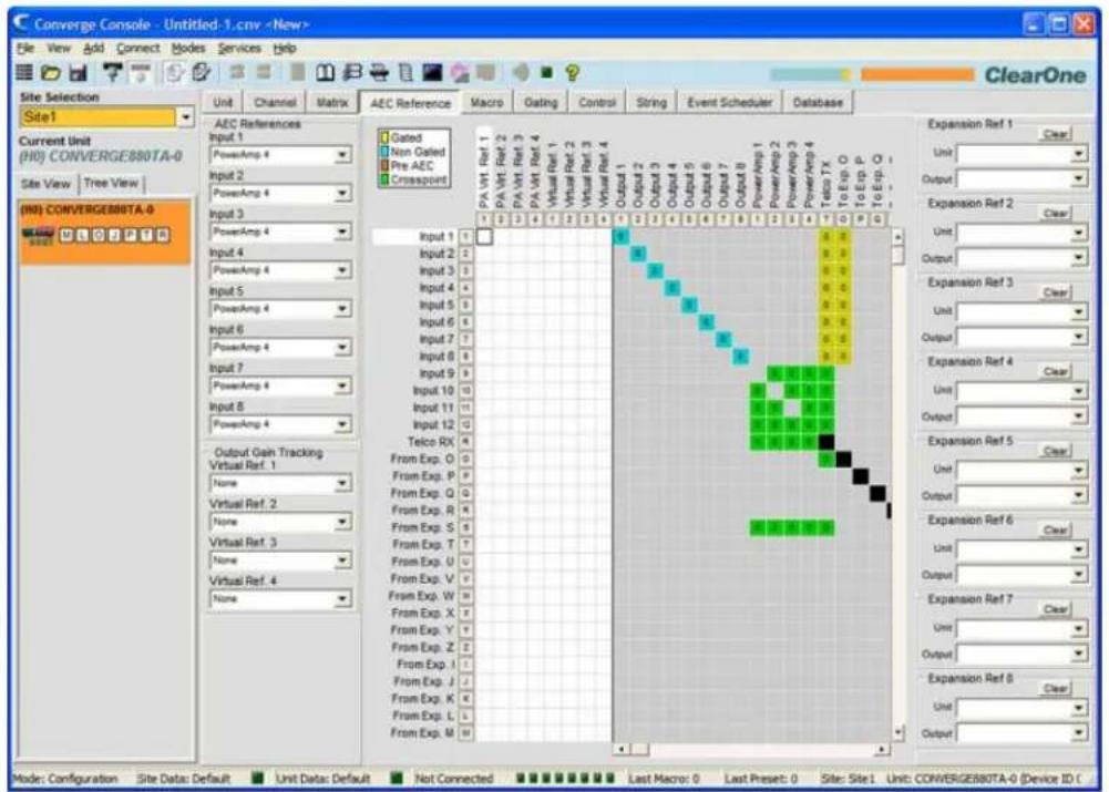
The AEC/PA Adapt Reference screen appears in the center pane of Console. AEC/PA Adapt reference configuration is explained in the following sections.
AEC/PA Adapt References Sources
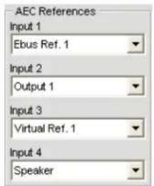
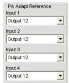
Use the drop-down lists to select an AEC/PA Adapt reference for each input channel as required for your application. As shown above, you can select any of the following as a reference source in the AEC/PA Adapt References section of the screen:
Output channels (880, 880T, 880TA, 840T, TH20, SR 1212, SR 1212A)
Expansion bus channels•
Speaker outputs (880T, 880TA, 840T only)
Virtual references (880, 880T, 840T, TH20, VH20, SR 1212, SR 1212A)
Virtual AEC/PA Adapt References
Virtual AEC/PA Adapt References allow you to combine multiple audio sources for applications where there are two speakers (left and right) providing audio, combined audio/video conferencing, and audio/video teleconferencing. In these and other multiple output applications, using virtual AEC/PA Adapt references improves AEC performance.
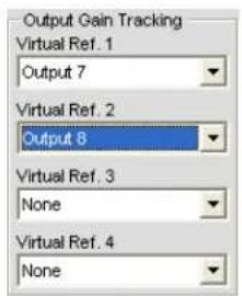
AEC requires a physical output reference to track output gain changes. Therefore when using virtual AEC/PA Adapt references, you must use output gain tracking to provide level information to the AEC process. Use the Output Gain Tracking section of the screen (shown above) to specify the level source for each virtual reference that you define.
Virtual AEC/PA Adapt reference sources are defined in a special section of the Matrix (shown below, highlighted in white):
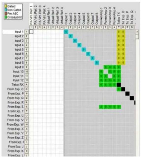
Use the white cross point area to select the outputs for each virtual reference source you want to define. In the example above, Output 7 is connected to the room amplifier. This audio includes microphones that cannot be included in the AEC reference, so Output 7 should not be used directly as the AEC reference source. Instead, use a
Virtual Reference and route any inputs that you want cancelled to that reference. This typically would include Telco/VoIP rx audio and audio from a video codec (Input 5 above), which in this example are combined to create Virtual Reference 1.
NOTE: If the channels selected for a virtual reference use Processing or Faders, you should select the processing or fader channel as the virtual reference source. This provides the AEC process with the most accurate reference for the signal, thereby providing faster convergence and more accurate AEC performance.
Expansion Bus Reference Sources
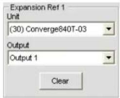
Use the Expansion References (1-8) section of the screen to use audio from an expansion bus channel as the AEC/PA Adapt reference source. For each expansion reference, select the Unit and the Output you want to use as a reference using the drop-down lists.
The following types of sources are available for use as expansion AEC/PA Adapt reference sources:
Output channels• Speakers• Virtual references•
PA Virtual References
A PA Virtual Reference assigns audio from a given amp output and applies the same processing to a corresponding Amp Channel. All processing and audio information is applied to the Amp Channel. (For example, if the feedback eliminator is enabled on PA channel 2 the feedback eliminator adds a new node. That same feedback node will be added to the audio contained on PA Virtual Channel 2.)
For more information, refer to the Table of Contents for these related topics:
AEC (Acoustic Echo Cancellation)
Mic Input Settings*
Processing Settings
Fader Settings•
MACRO TAB
Macros define a series of commands which can be run using the Front Panel LCD, Serial Commands, Control Ports, Presets, the Web Portal, SNMP, and other macros.
Macros allow you to make quick configuration changes and to execute multiple Presets simultaneously. Macros can also contain commands that are executed on other units on the E-bus.
All models support up to 255 macros (with an average of 150 command lines each). In the unlikely event that you exceed Console's memory capacity, a warning appears indicating the command line at which memory is exceeded.
Accessing Macros
To access macros, press the Macro Tab on the Tab Bar in Console.
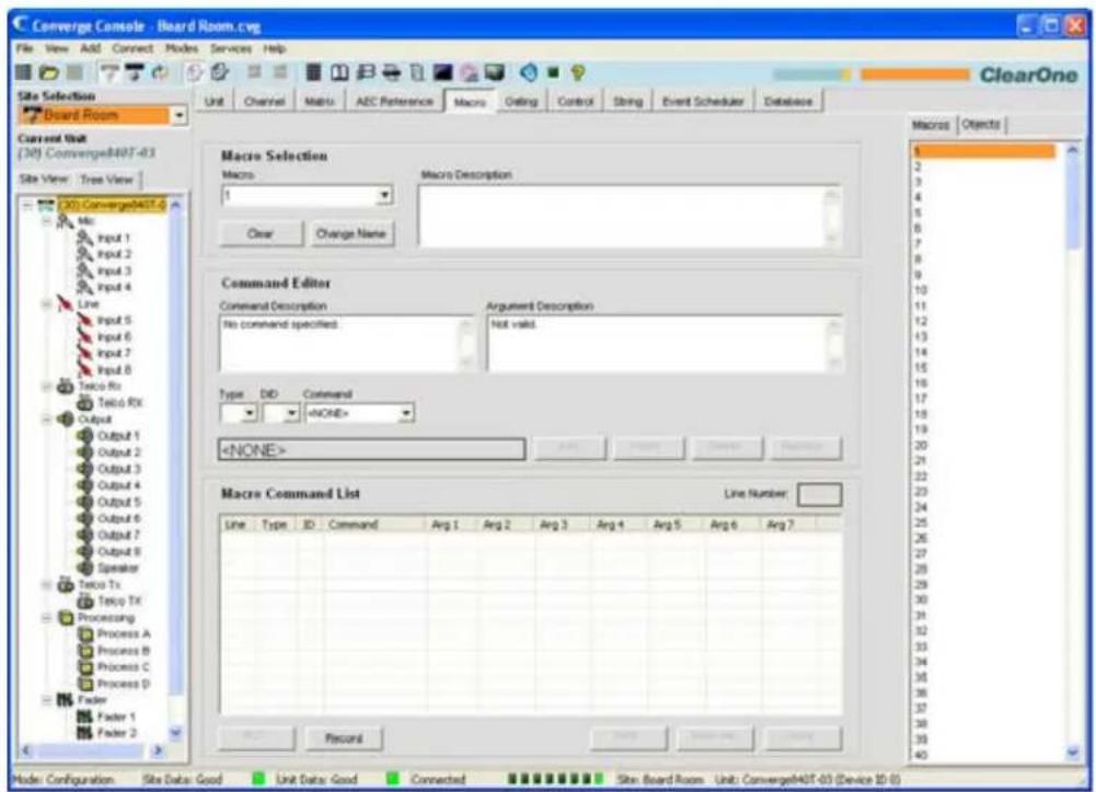
There are two ways to create macros in Console: the Macro Recorder, which records screen selections, and the Macro Editor, which allows you to create command lines. The Macro Editor is also used to modify macros created using the Macro Recorder.
Macro Recorder
Use the following procedure to record a macro using Macro Recorder:
- Click the Record button at the bottom of the Macro screen. The Macro dialog appears.
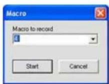
-
Select the macro number from the Macro to Record drop-down list, then click Start. The Macro Record dialog appears (shown below).3.
-
In the Console, make the routing and input/output configuration changes (such as gain adjustments, mute, etc.) that you want to include in the macro.
- Click Stop in the Macro Record dialog to end macro recording. The macro Command Editor appears with a list of the commands captured.6.
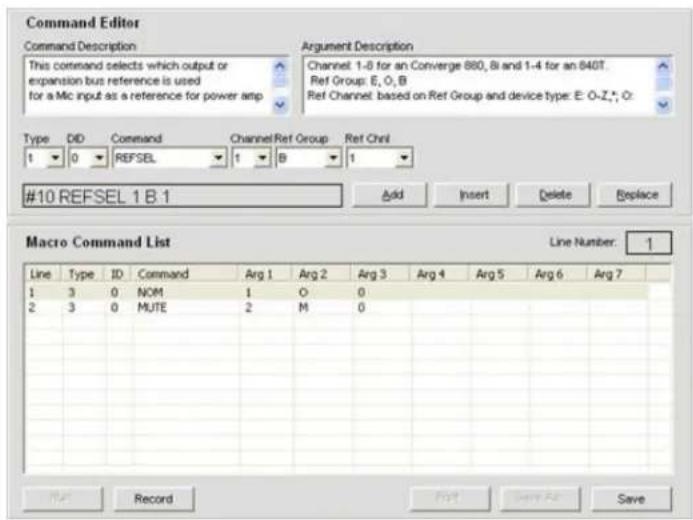
Click 7. Save to save the macro.
You can use the Macro Editor to modify recorded macros as described in the next section.
Macro Editor
Creating Macros
Use the following procedure to create a macro using the Macro Editor:
- Select the Macro number to create from the Macro drop-down list.

NOTE: Used macros are indicated by an asterisk in the macro drop-down list.
- Press Change Name to assign a name to the macro (optional). Enter the name into the Change Name dialog that appears.
NOTE: Macro names appear in Console macro lists and on the LCD Macro menu. Using brief descriptive names makes it easier to identify a macro's functionality.
- Enter a description of the macro's functionality in the Macro Description entry field (optional).
- Select the device Type, DID (Device ID number), and Command from the drop-down lists.
- When you select a command, a description of it appears in the Command Description box. The parameters associated with the command also appear, along with the valid values or range for each parameter, in the Argument Description box (shown below).
Set the parameter values for the command as required (optional). 6.
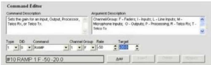
- Click Add to add the command to the end of the macro, or Insert to insert the command before the currently selected row of the macro. The command appears in the Macro Command List.
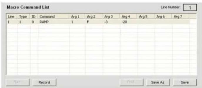
NOTE: When there are multiple commands in the Macro Command List, you can drag and drop them to change their execution order.
You can now add another command (repeat steps 4 through 6), or click Save or Save As to save the completed macro.
Modifying Macros
Use the following procedure to edit a macro:
- Select the Macro number to modify from the Macro drop-down list.
- Click Change Name to change the macro name (optional).
- Double-click the command line in the Macro Command List you want to edit. Modify the command or its arguments by selecting options from the drop-down lists.4.
- Click Replace to overwrite the old command line with the new changes.
- Click Insert to insert a new command, or Delete to delete the currently highlighted command.
- When you are finished making changes, click Save or Save As to save the macro.
Deleting Macros
Use the following procedure to delete a macro:
- Click Clear Macro to delete the entire macro.
- Click Delete to delete the selected command line.
Adding and Inserting Command Lines
Use the following procedure to add or insert command lines into the currently selected macro:
- Click Add to place the current command line into the next available row in the command line table.
- Click Insert to insert the current command line into the row directly above the currently selected command line in the table.
- When you are finished making changes, click Save or Save As to save the macro.
Running Macros
Running Macros Using Console
Use the following procedure to run a Macro from Console:
- Select the Macro tab from the Console main screen or press the Run Macro button on the button bar (only available when Console is in Configuration mode).
- Select the macro from the Select Macro list.
- Click Run to run the macro and close the window.
Running Macros Using the Front Panel
Use the following procedure to run a macro from the front panel:
- Using the Menu Dial, select the Macros Menu.
- Select the macro you want to run from list and press the Select button.
- Answer Yes when prompted to run the macro, or No to cancel.
Running Macros Using Control Devices
Refer to the Control Tab topic for information on running macros using control devices.
Exporting Macro Objects
Macro Objects allow you to save macros into the Database and reuse them. To capture a macro and save it as an object, right click anywhere in the center pane of the macro screen and select Export as object from the shortcut menu.
For more information about objects, see Creating Channel Objects, Matrix Objects, Control Objects, and Drag & Drop Configuration.
For additional information, refer to the Table of Contents for these related topics:
• Controls and Connections
- Expansion Bus Overview
- Device IDs
• LCD Programming Overview
- LCD Macros Menu
- Presets
- Configuration Mode
- Control Tab
- Database
- Channel Objects
- Matrix Objects
- Control Objects
- Drag & Drop Configuration
GATING TAB
The Gating tab allows you to create gating groups and assign mic inputs to gating groups.
Gating group assignments combine individual channel gating configurations created using the Channel Properties Configuration screen. When inputs are assigned to a gating group, the gating information from the assigned inputs is used to control how the entire mixer behaves.
The Converge/Converge Pro product family (excluding the TH20/VH20) features four internal gating groups (Internal 1–4), and six global gating groups across the expansion bus (Global A–F). Mic inputs are assigned to Global Group A by default. If an input is not assigned to a gating group, that mic's gating properties are independent, and they have no effect on any gating group. When gating groups span two or more units (global gating groups), the settings must be the same for each unit attached to the global gating group.
NOTE: Mic inputs can be assigned to one and only one Gating Group at a time.
Accessing Gating Groups
To access gating groups, click the Gating Tab on the Tab Bar in Console.
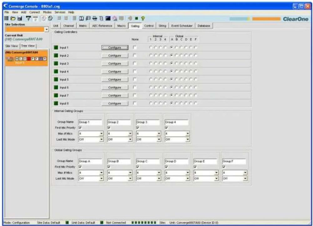
Gating configurations are shown in the Center Pane. The following sections describe how to configure gating groups.
Gating Controllers
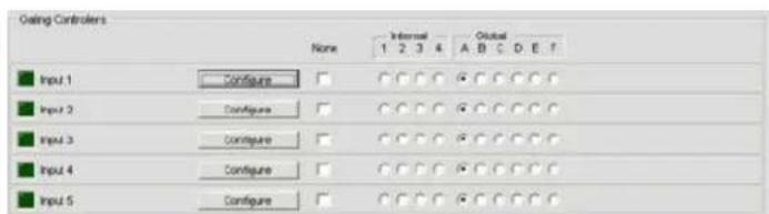
Use the Gating Controllers section of the screen to assign Mic Inputs to a gating group. Use Internal gating
groups (radio buttons 1-4) to control mic inputs connected to the unit currently selected in the Site Pane. Use Global gating groups (radio buttons A-F) to control mic inputs connected to the current unit, as well as all units connected to the E-Bus.
Press the Configure button to display and modify individual channel Gating configurations using the Channel Properties Configuration screen.
Internal Gating Groups
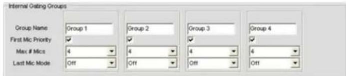
Internal gating groups control mic inputs connected to a specific unit. Configure Internal Gating Group settings as follows:
- Enter a name in the Group Name field (optional).
- Select the First Mic Priority checkbox to enable this feature (default), or deselect it to turn First Mic Priority off.
NOTE: ClearOne recommends using First Mic Priority to maintain maximum audio intelligibility by allowing only one mic to gate on to a participant's voice. First Mic Priority allows more than one microphone to gate on at same time, but it restricts more than one mic from gating on to the same audio source. It does this by determining the audio level received by all mics when the first mic is gated on, and then using this audio level as the ambient level for the gating group. If First Mic Priority is disabled, two or more microphones will usually gate on when only one person speaks.
- Select the Max # of Mics from the drop-down list (the default is 4). This sets the maximum number of microphones that can be gated on at any one time within a gating group. The maximum number of mics is limited to the number of mics included in the gating group. For internal gating groups, the maximum number of mics is 8 for Converge Pro 880, 880T, 880TA 8i, Converge SR 1212 and SR 1212A units, and 4 for Converge Pro 840T units.
- Select the Last Mic Mode from the drop-down list (the default is off). Last On leaves the last mic activated gated on until another mic gates on. The Input options allow you to select which mic remains on when all other mics gate off. Off gates all mics off when no audio is present. All allows all mics to gate on at the same time.
Global Gating Groups

Global gating groups control mic inputs connected to all units linked together through the Expansion Bus. Configure Global Gating Group settings as follows:
- Enter a name in the Group Name field (optional).
- Select the First Mic Priority checkbox to enable this feature (default), or deselect it to turn First Mic Priority off.
NOTE: ClearOne recommends using First Mic Priority to maintain maximum audio intelligibility by allowing only one mic to gate on to a participant's voice. First Mic Priority allows more
than one microphone to gate on at same time, but it restricts more than one mic from gating on to the same audio source. It does this by determining the audio level received by all mics when the first mic is gated on, and then using this audio level as the ambient level for the gating group. If First Mic Priority is disabled, two or more microphones will usually gate on when only one person speaks.
- Select the Max # of Mics from the drop-down list (the default is 4). This sets the maximum number of microphones that can be gated on at any one time within a gating group. Again, the maximum number of mics is limited to the number of mics included in the gating group. For global gating groups, the maximum number of mics is eight, up to a maximum of 96 microphones in E-bus linked systems.
- Select the Last Mic Mode from the drop-down list (the default is off). Last On leaves the last mic activated gated on until another mic gates on. The Input options allow you to select which mic remains on when all other mics gate off. Off gates all mics off when no audio is present.
For additional information, refer to the Table of Contents for these related topics:
Mic Input Settings•
Channel Tab Overview•
Mic Gating•
Expansion Bus Overview•
CONTROL TAB
The Control Tab allows you to configure pin assignments for the user-definable pins on Control/Status Port A and Control/Status Port B.
All models implement control/status using DB-25 pin ports on the back panel, and GPIO (General Purpose Input Output) with active low/pull to ground inputs and open collector outputs. For details, refer to Appendix B and the Control/Status Ports section of Appendix D: Specifications.
The control ports enable external devices to access the Converge/Converge Pro serial command set, including common functions such as volume control, muting, room combining, and preset changes. All devices connected via the E-bus can be controlled from a single control/status port on any of the devices.
Accessing the Control Tab
To access command control, press the Control Tab on the Tab Bar in Console.
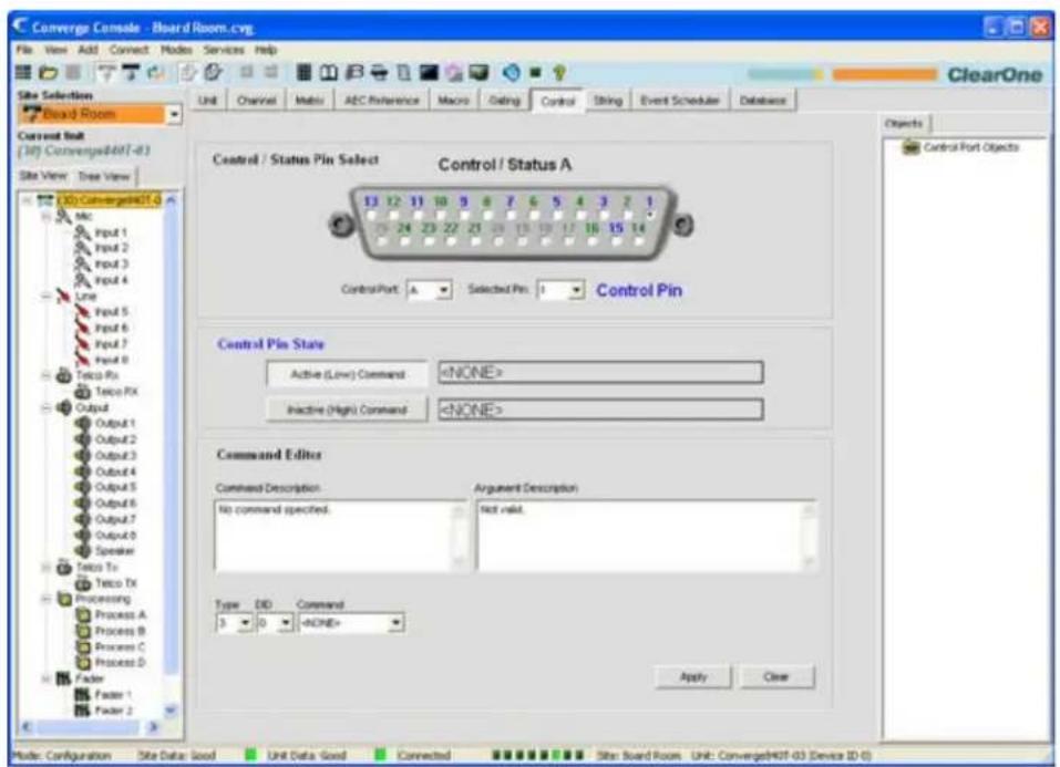
The Control tab of the Console main screen shows a graphical representation of Control/Status Port A. The pins numbered in blue are user-definable command pins; the pins numbered in green are status pins. Control interface functionality and pin programming are explained in the following sections.
User-Definable Pins
The user-definable pins provide control via contact closure, and status via open collector functions in the unit. There are two user-definable pins on the B port of every unit. The number of user-definable pins on the A port varies by model, as summarized in the following table:
| Model User-Definable PinsControl/Status Port A | User-Definable PinsControl/Status Port B |
| 880 16 2 | |
| 880T 16 2 | |
| 880TA 16 2 | |
| 840T 20 2 | |
| 8i 16 2 | |
| TH20 24 2 | |
| VH20 24 2 | |
| SR 1212 16 2 | |
| SR 1212A 16 2 |
Default Pin Assignments
For default pin assignments for Control/Status ports by model, refer to Appendix B.
Control/Status Ports
Control/Status A and B ports are female DB25 connectors used for General Purpose Input/Output (GPIO) interactions between Converge/Converge Pro devices and external control devices such as wall switches and push-to-talk microphones. Control programming enables external control devices and controller software to access the Converge/Converge Pro serial command set, including common functions such as volume control, muting, room combining, and running presets.
For more information on Control/Status Port A and B and other physical connections, see Controls and Connections.
Control/Status Pin Programming
Use the following procedure to program user-definable pins:
- In the Control/Status Pin Select section of the screen, select port A or B from the Control Port drop-down list.
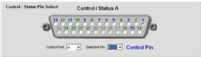
- Select the pin you want to configure from the Selected Pin drop-down list. (Pin 1 is selected by default for Control Port A and Pin 21 is selected by default for Control Port B.)

- In the Control Pin State section of the screen, press the Active (Low) Command or Inactive (High) Command button to select the pin state that you want to associate a command with.
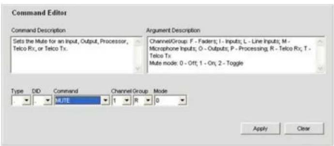
- In the Command Editor section of the screen, select the device Type, DID, and Command from the drop-down lists. When you select a command, its description appears in the Command Description box. The parameters associated with the command appear next to the Command drop-down list, and the valid values or range for each parameter appear in the Argument Description box.

- Set parameter values for the command as required, then press the Apply button. The command appears in the selected Active/Inactive Command text box.
- To complete programming for the selected pin, repeat steps 3 through 6 to set the Active Command for the opposite pin state.
Repeal steps 1 through 6 to program additional pins.7.
Clearing Pin Programming
To clear programming for a pin, select the Control Port and Selected Pin using the drop-down lists, select the pin state using the Active Command buttons, then press the Clear button. To clear all pins, right-click and select Clear All from the shortcut menu.
Exporting Control Objects
You can save control port objects into the Converge/Converge Pro database. To capture the currently displayed control pin programming, right click in the Control/Status Pin Select portion of the of the Control Tab screen, and select Export as object from the shortcut menu. After saving the control port object, it appears in the Objects pane on the right side of Console.
For more information about objects, see Creating Channel Objects, Matrix Objects, Macro Objects, and Drag & Drop Configuration.
For additional information, refer to the Table of Contents for these related topics:
Expansion Bus•
Controls and Connections•
Device IDs (DIDs)
String Tab·
STRING TAB
The String Tab enables you to create up to eight command strings that allow Converge/Converge Pro units to control external devices such as lighting, projectors, and room dividers. Command strings are written using the syntax of the external device being controlled. Converge/Converge Pro devices pass command strings to external devices through the RS-232 port.
Accessing the String Tab
To create command strings, press the String tab on the Tab Bar in Console.
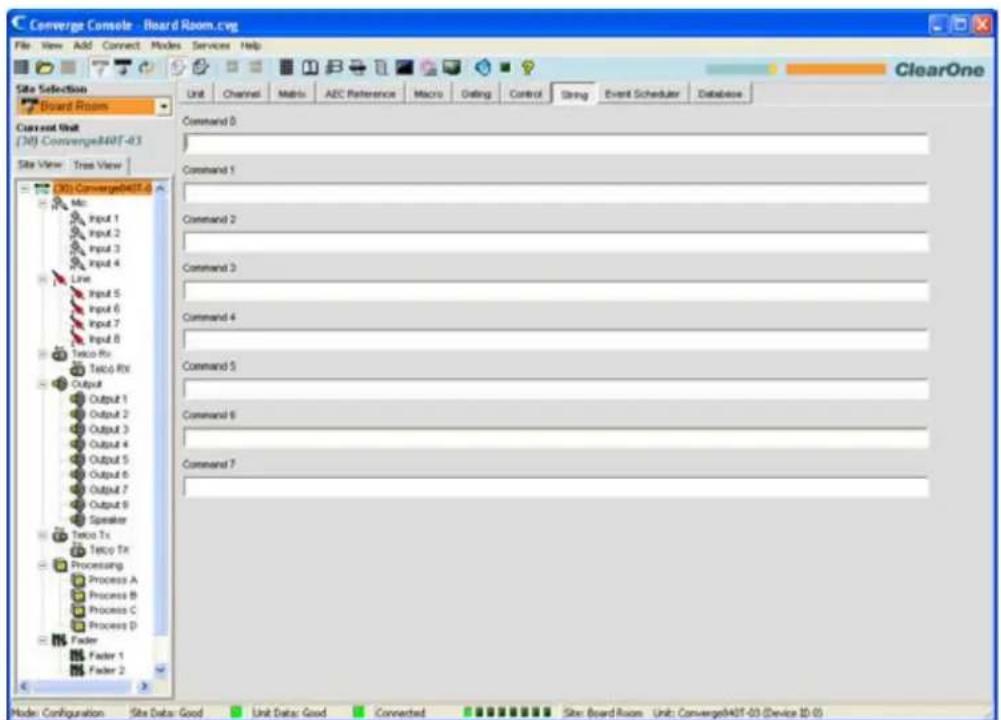
You can create up to eight serial command strings (limit 80 characters each) on the String screen. The following sections explain how to create and run command strings.
Command String Special Characters
The following character combinations provide basic functionality in Command String syntax:
\a• = alert
\b• = backspace
\f• = form feed
\n• = new line
\r• = carriage return
\t• = horizontal tab
\v• = vertical tab
\|\• = backslash
Creating Command Strings
Type a command string in the Command 0 through Command 7 text boxes in the center pane of the Control Tab. Alternatively, you can copy an existing string from any source, then right-click in a Command entry box and select Paste from the shortcut menu that appears.
Running Command Strings
Console stores the commands strings created in the Control tab for subsequent execution via the STRING serial command. You can execute the STRING command in macros, using control pin programming, in the Event Scheduler, and from the Control Console page of the Web Builder tab. Using macros also enables you to execute command strings from external control devices. See the Control Tab topic for more information.
For additional information, refer to the Table of Contents for these related topics:
Controls and Connections•
Front Panel•
Control/Status Port•
Gating Tab·
Macro Tab•
Event Scheduler•
Control Tab•
EVENT SCHEDULER TAB
The Event Scheduler allows you to schedule commands for execution at a specific time (events). Using the event scheduler, you can schedule single events or recurring events that are executed at pre-defined time intervals.
Accessing the Event Scheduler
To schedule events, press the Event Scheduler Tab on the Tab Bar in Console.
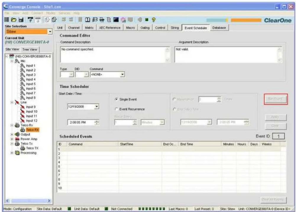
Scheduling Events
Events must be scheduled and run on the local device. However, commands can be sent from events to other devices in the site using Macros.
Use the following procedure to schedule events:
- In the Command Editor section of the screen, select command from the Command drop-down list. The command description appears in the Command Description box, parameters appear next to the Command drop-down list, and the valid values for each parameter appear in the Argument Description box.
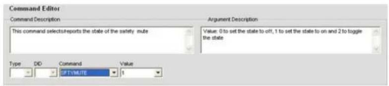
The commands available for event scheduling include:
MACRO• –Executes a macro
PRESET• -Executes a preset
RESET• –Resets the specified device
SFTYMUTE• -Mutes all channels on the specified unit
STRING• –Runs a command string
SYSCHECKS• –Runs system diagnostics
- To schedule a single event, select Single Event and set the desired Start Date/Time in the Time Scheduler section of the screen.
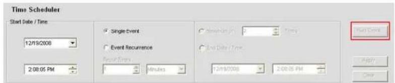
- To schedule a recurring event, select Event Recurrence; set the recurrence interval using the Recur Every fields; and select either Maximum of Times or End Date/Time to specify the number of repetitions or time period for event execution respectively.
NOTE: Clicking on the arrow button next to a date entry field in the Time Scheduler section of the screen displays a calendar for date selection.
- Click the Apply button to schedule the event. The event appears in the Scheduled Events List.
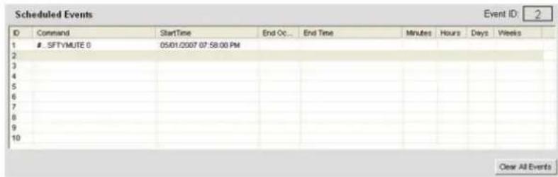
-
Add additional events as required by repeating steps 1 through 4.
-
To clear a single event, highlight the event and press Clear. To clear all scheduled events, press the Clear All Events button. Answer Yes in the Warning dialog that appears.
NOTE: Events can also be viewed and scheduled via the Management page of the Web Portal.
For additional information, refer to the Table of Contents for these related topics:
Macro Tab·
Preset Mode Overview
Safety Mute•
String Tab·
System Checks•
- Web Builder
DATABASE TAB
NOTE: Objects and Devices created in Console 1.0.4 and 1.1.5 are NOT compatible with Console 2.0+ Objects and devices created with these earlier versions will need to be re-created. Databases created with the 2.0.x release are compatible with the 3.0.x release.
The Database Tab enables you to create, modify, and save AV devices, channel objects, and advanced objects. AV devices allow you to save pre-defined configurations for a particular type of device, such as a ceiling microphone. Channel objects allow you to save pre-defined configurations for a channel. Advanced objects allow you to save matrix, macro, control, and preset objects for advanced configuration and automation tasks.
Using AV devices and channel objects, you can create standardized configurations for particular room types and equipment, and quickly configure a venue. See Drag & Drop Configuration for more information.
Accessing the Database
To access the Database, select the Database Tab from the Tab Bar in Console.
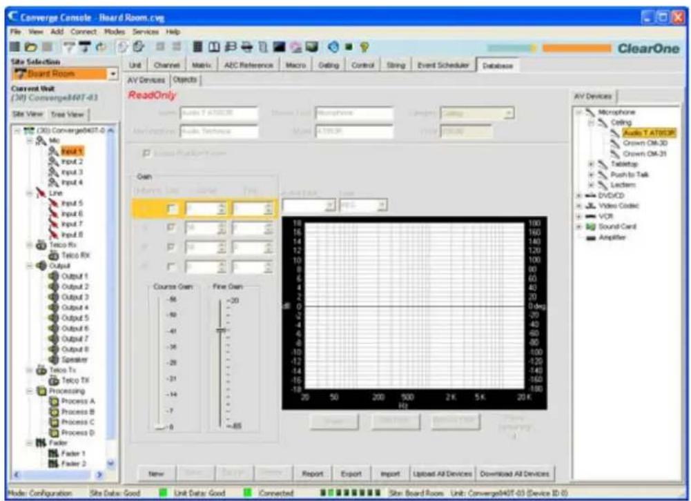
As shown above, there are two tabs available in the center pane: AV Devices and Objects. A corresponding tab is displayed in the Object Pane on the right side of the screen. The Database Button Bar is located at the bottom of the Center Panel. These components are described in the following sections.
NOTE: Advanced object types are not viewable in the Database Tab
Database Button Bar
The Database Button Bar (shown below) allows you to create, save, delete, export, import, upload, and download AV Devices and Objects. Buttons available change based on the device/object selected and the status of the configuration screen displayed in the center pane.
| New | Save | Cancel | Delete | Report | Export | Import | Upload All Devices | Download All Devices |
Click the Report button to view and print a report of all AV devices.
AV Devices
AV devices allow you to save pre-defined configurations for a particular type of device, such as a ceiling microphone. To access AV devices, expand the AV Device Tree in the AV Devices Tab in the Object Pane on the right side of Console. Click on a device in the tree to display its configuration in the center pane. For example, the default settings for a ClearOne tabletop microphone are shown below.
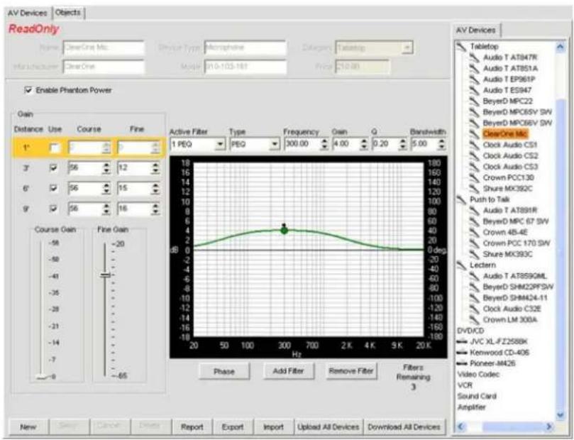
NOTE: Pre-defined AV devices created by ClearOne are ReadOnly as indicated in the center pane. They cannot be modified or deleted.
Creating A New AV Device
To create a new AV device, select the type of device you want to create in the AV Devices Tree, then click the New button on the Database Button Bar. The configuration options for that type of device appear on the AV Devices Tab in the Center Pane. For example, the configuration options for a new Video Codec device are shown below.
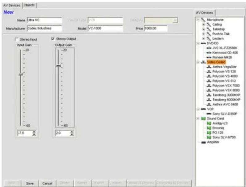
Name the new device using the Name field. Enter other information as needed, adjust the configuration controls to optimize device performance, and click the Save button to save the changes.
The new device now appears in the AV Device Tree as shown below.
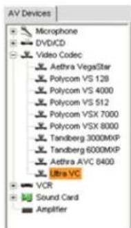
NOTE: The AV Device Tree is also available when the Unit Tab is selected, making all pre-defined and custom AV Devices available for Drag and Drop Configuration of a venue.
Channel Objects
Channel objects allow you to save pre-defined configurations for a channel, such as an Output channel. To access objects, select the Objects tab in the center pane. The Object Tree appears in the Object Pane on the right side of the screen as shown below.
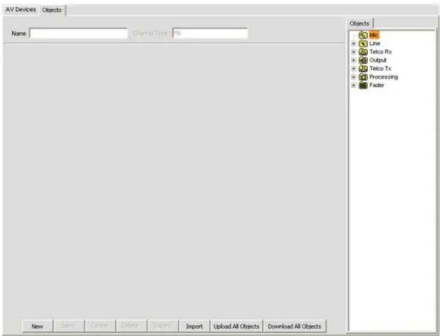
Available channel object types include:
Mic Input•
Line Input•
Telco/VoIP rx•
Output·
Telco/VoIP tx•
Processing•
Fader Channels•
To create a new channel object, select an object type in the Object Tree and click the New button. Enter a name for the object in the Name field, adjust the channel configuration controls to optimize channel performance for your application, and press the Save button. The new channel object appears in the Object Tree, along with all other custom channel objects you have created, as shown below.
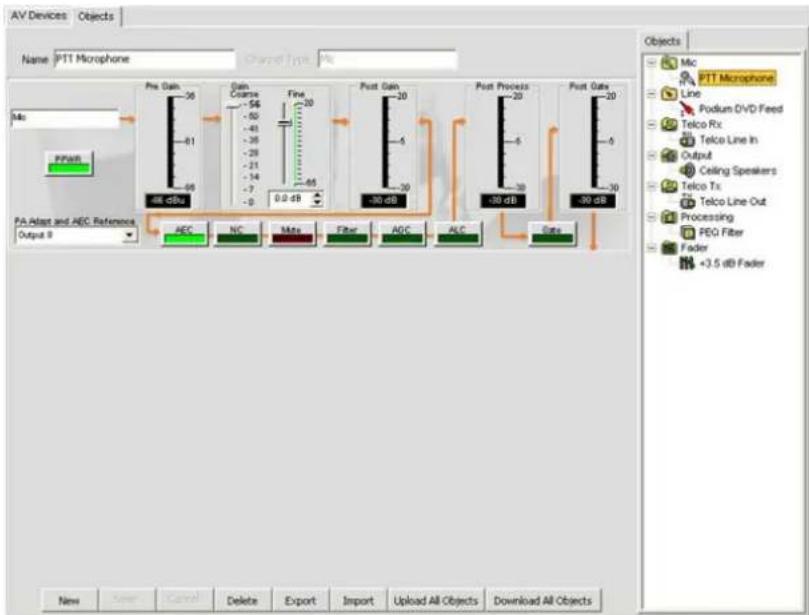
NOTE: The Object Tree is also available when either the Unit Tab or the Channel Tab is selected, making all custom channel objects you have defined available for Drag and Drop Configuration of a venue.
Import/Export AV Devices and Objects
All AV Devices and channel Objects are stored as .XPT files and .XMO files respectively on the host computer or network. To import or export these files, use the Import and Export buttons on the Database Button Bar. These features enable you to share device and object file definitions across sites, applications, and venues.
Upload/Download AV Devices and Objects
To upload or download ALL AV Devices or channel Objects in the database, use the Upload and Download buttons on the Database Button Bar. These features enable you to share databases among sites, applications, and venues.
Modifying AV Devices and Objects
To modify AV Devices and channel Objects, select the device or object in the Object Pane, modify the configuration settings for the device or object in the Center Pane, and click the Save button on the Database Button Bar. When you make changes to the device or object, Edit appears at the top of the Center Pane.
NOTE: Pre-defined AV devices created by ClearOne are ReadOnly as indicated in the center pane. They cannot be modified or deleted.
For additional information, refer to the Table of Contents for these related topics:
Site Properties•
Unit Properties•
Unit Tab·
Channel Tab Overview
Line Input Settings•
Mic Input Settings•
Telco/VoIP rx Settings •
Output Settings
OPTIMIZING GAIN STRUCTURE
Optimizing Gain Structure maximizes the signal-to-noise ratio for each channel, optimizes the performance of processing functions, and ensures optimal audio quality.
Use these guidelines when optimizing initial gain structure for a venue:
Connect all input sources and output devices to the Converge/Converge Pro unit(s).
- Turn off all processing functions, including AGC/ALC (Automatic Gain Control/Automatic Level Control), NC (Noise Cancellation), and Filters.
Optimize all mic and line inputs that are routed to an output before optimizing the output.
- When optimizing output channels, the objective is to match the output to the nominal gain of the input of the device that is connected to the output channel.
- In general, turn NOM off when an output channel feeds an amplifier. Turn NOM on when optimizing telco/VoIP tx channels, in sound reinforcement applications, and when optimizing for video codec configurations.
• After optimizing gain using the procedures below, re-enable processing functions and NOM as required.
Optimizing Gain for Mic Input Channels
- Open the Channel Tab and select the Mic Input on the Tree View Tab that you want to optimize, as shown below.
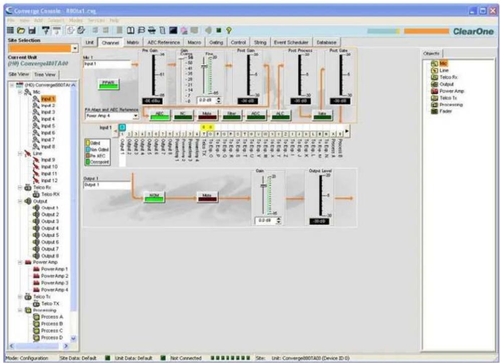
- Have somebody repeat a test count at a normal distance from the microphone (generally this would be seated at the conference table or positioned for a video teleconference).
- Adjust the Coarse Gain Slider until the peaks on the Post Gain Meter are close to +6dB (just hitting yellow), and the average level is close to 0dB.
- Adjust the Fine Gain Slider until the peaks on the Post Gain Meter are as close to +6dB and the average level is as close to 0dB as possible.
- Repeat the above steps for each mic input in the venue.
NOTE: The Post Gain Meter is a peak meter. If the meter remains green, the level may be too low. If it peaks into red, clipping occurs.
Optimizing Gain for Line Input Channels
Line inputs are optimized using the same procedure as mic inputs, with the following exceptions. Select the Line Input you want to optimize on the Tree View Tab. With the line source connected, monitor the Post Gain Meter and adjust the gain level.
NOTE: Line sources, including video codecs, consumer grade CD players, DVD players and VCRs, commonly require 10-12 dB of gain to bring their levels up to 0 dBu.
Optimizing Gain for Telco/VoIP rx Channels
Optimize telco/VoIP rx inputs using the same procedure as mic inputs, with the following exceptions. Select Telco/VoIP rx on the Tree View Tab. With someone talking on the phone, monitor the Post-Gain Meter and adjust the gain level.
Optimizing Gain for Telco/VoIP tx Channels
Optimize telco/VoIP tx outputs using the same procedure as output channels, with the following exceptions. Select Telco/VoIP tx on the Tree View Tab. With someone speaking into the microphones routed to the telco/VoIP tx, monitor the Post Gain Meter and adjust the gain level.
NOTE: Use a standard handset on the far end because levels can be unpredictable from speaker phones and amplified headsets.
Optimizing Gain for Output Channels
- Open the Channel Tab and select the Output Channel on the Tree View Tab that you want to optimize, as shown below.
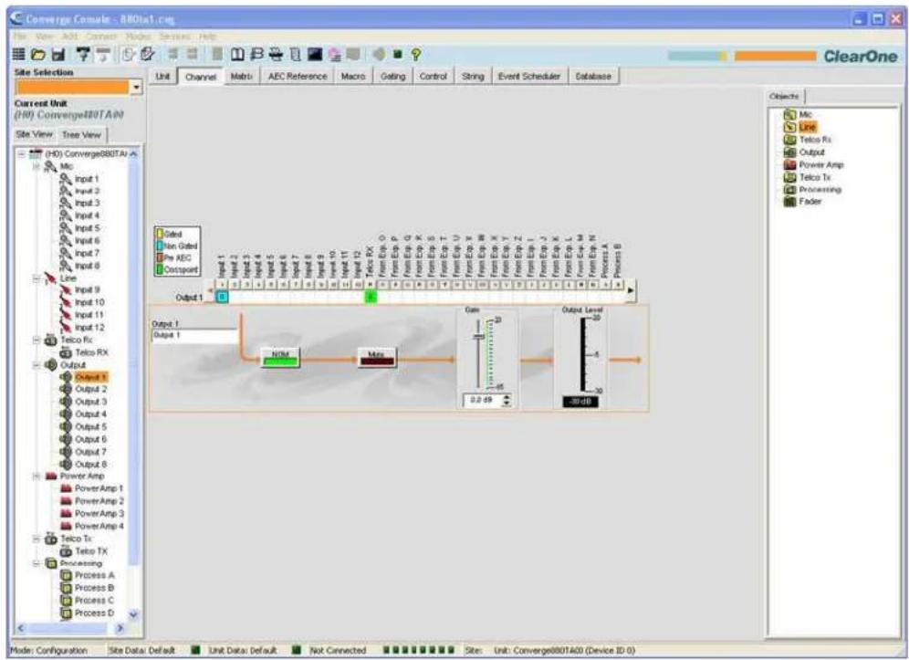
- Optimize the gain level for all mic, line, and telco/VoIP rx inputs routed to the selected output channel.
- Adjust the Gain Slider until the average level on the Gain Meter matches the nominal level of the next
device in the chain.
- Repeat the above steps for each output channel in the system.
For additional information, refer to the Table of Contents for these related topics:
Configuration Mode Overview•
Mic Input Settings
Line Input Settings•
Telco/VoIP rx Settings •
Telco/VoIP tx Settings •
Output Settings
AEC (Acoustic Echo Cancellation) •
AGC/ALC (Automatic Gain Control/Automatic Level Control)
NC (Noise Cancellation)
Filters•
DRAG AND DROP CONFIGURATION
NOTE: Objects and Devices created in Console 1.0.4 and 1.1.5 are NOT compatible with Console 2.0+ Objects and devices created with these earlier versions will need to be re-created.
Console provides powerful Drag and Drop Configuration capabilities that allow you to quickly configure Converge/Converge Pro devices and perform advanced system configuration tasks.
The types of objects available in Console for drag and drop configuration include:
AV Devices
Channel Objects
Matrix Objects
Control Objects
Macro Objects
Preset Objects
Accessing Drag and Drop Configuration
To select objects for drag and drop configuration, use the Objects Pane on the right side of Console. The objects available in the objects pane vary depending on the tab selected on the Console Tab Bar. For example, when the Unit Tab is selected, both AV devices and channel objects are available as shown below.
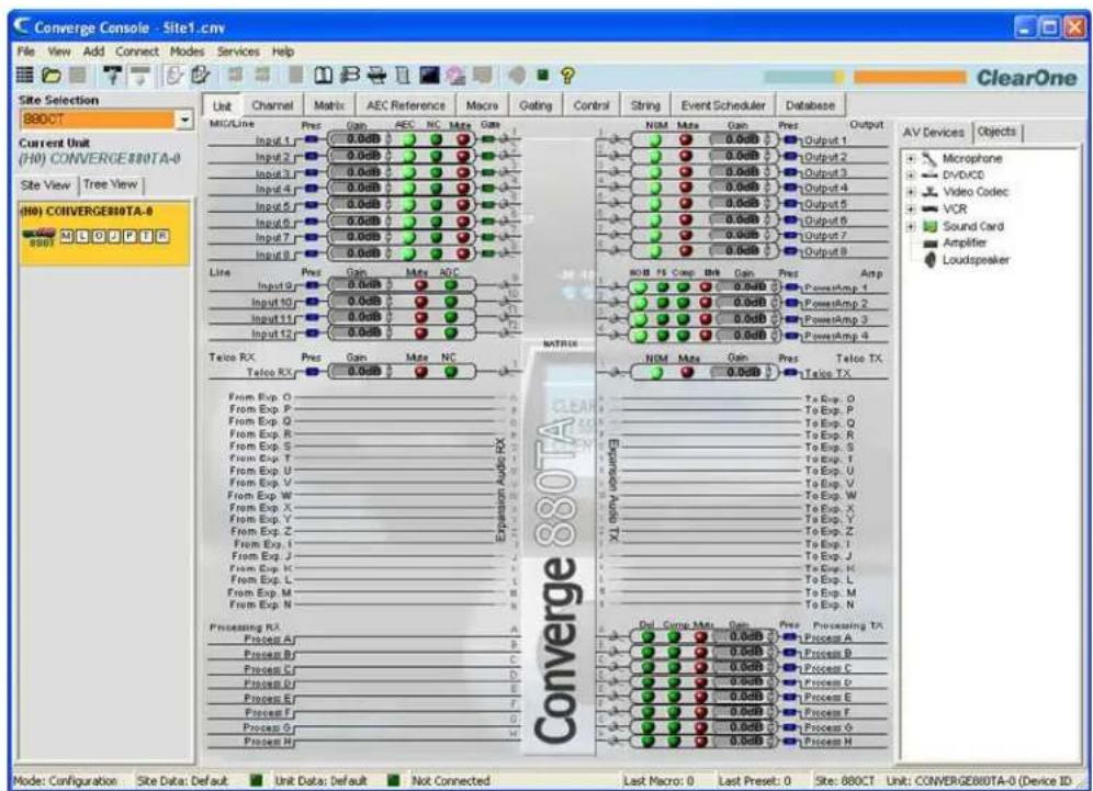
Using Drag and Drop Configuration
Drag and drop configuration is a three step process for all object types:
Create an object1.
Store it in the Database2.
- Drag the object from the Objects pane onto a channel or screen area (as appropriate for the object type)
The following sections describe creating and applying objects in Console.
Creating Objects
With the exception of custom AV devices, which can only be created using the Database Tab, all objects can be created by right clicking on a screen and using the shortcut menu that appears.
For example, to capture the currently displayed control pin programming as a control port object, right click in the Control/Status Pin Select portion of the of the Control Tab screen, and select Export as object from the shortcut menu (see below).
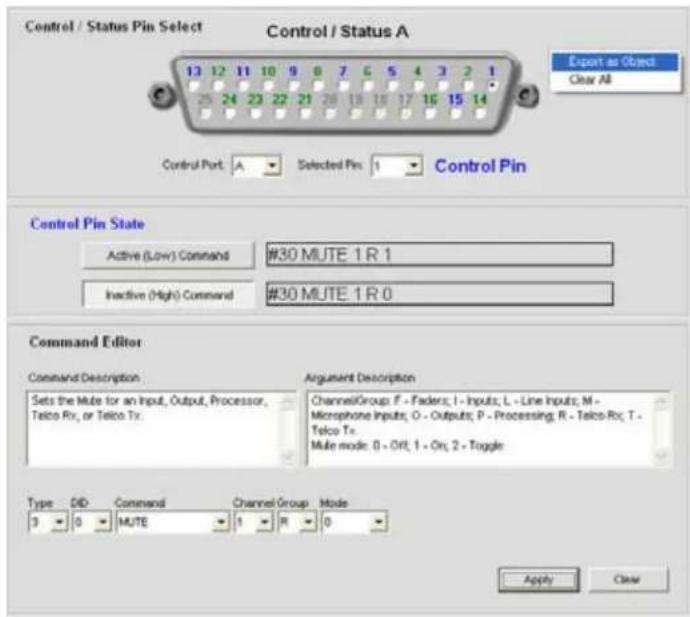
The Export Object dialog appears as shown below. Assign the object a name and press Export.
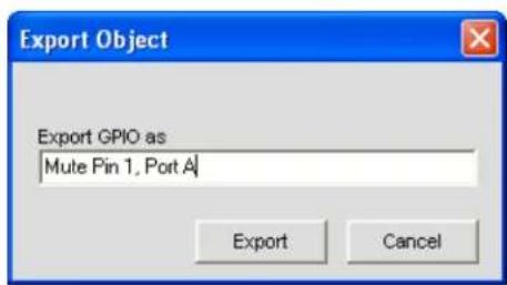
The control object now appears in the objects pane as shown below.
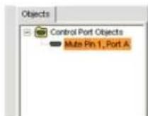
The object is now available for drag and drop configuration.
AV Devices
ClearOne provides numerous pre-configured AV devices, with settings that optimize the performance of the device for a typical (baseline) room. These devices are available in the AV Devices tab of the Objects Pane as shown below. Click a device type in the AV Device Tree to show the available devices of that type.
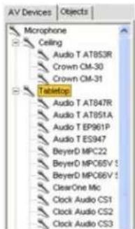
To apply an AV device to a channel, drag the object onto the channel in the Unit or Channel tabs. For example, to apply a Crown PCC130 tabletop microphone to Mic/Line Input 1, select the object from the AV Devices tree and drag it onto the channel.
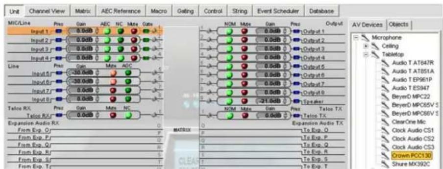
A dialog prompts you for the distance of the microphone to the talker. Select a value and press OK to apply the object to the channel.
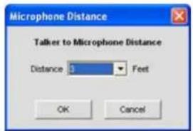
A microphone icon appears next to the channel, indicating that the channel is using an AV device object configuration.
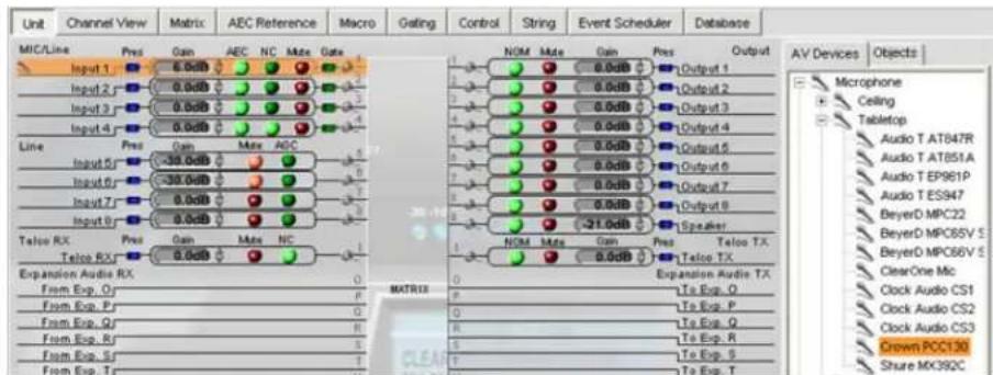
Click on the microphone icon to view object properties and enter a serial number in the AV Devices Properties dialog.
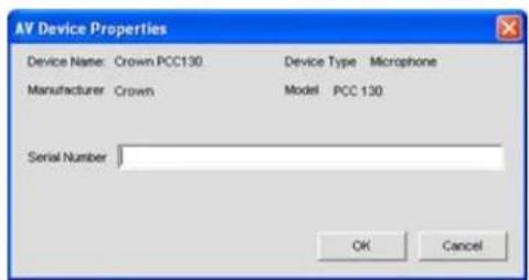
To view detailed information about an AV device's configuration settings, or to create a custom AV device, use the AV Devices pane of the Database tab.
Channel Objects
In addition to using AV devices, you can drag and drop Channel Objects in the Unit Tab and the Channel Tab to instantly apply a saved configuration to a channel. You can save channel objects for all Converge channel types, including Mic Input, Line Input, Telco/VolP rx, Telco/VolP tx, Output, Processing, and Fader channels.
For example, you can configure NOM, mute, and gain settings for Output 1 on the Channel tab as shown below.
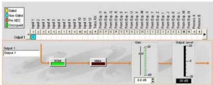
flowchart
graph LR
    A["Input 1"] --> B["Input 2"]
    B --> C["Input 3"]
    C --> D["Input 4"]
    D --> E["Input 5"]
    E --> F["Input 6"]
    F --> G["Input 7"]
    G --> H["Input 8"]
    H --> I["Input 9"]
    I --> J["Input 10"]
    J --> K["Input 11"]
    K --> L["Input 12"]
    L --> M["Tribo FO"]
    M --> N["From Exp O"]
    N --> O["From Exp P"]
    O --> P["From Exp Q"]
    P --> Q["From Exp R"]
    Q --> R["From Exp S"]
    R --> S["From Exp T"]
    S --> T["From Exp U"]
    T --> U["From Exp V"]
    U --> V["From Exp W"]
    V --> W["From Exp X"]
    W --> X["From Exp Y"]
    X --> Y["From Exp Z"]
    Y --> Z["From Exp I"]
    Z --> AA["From Exp J"]
    AA --> AB["From Exp K"]
    AB --> AC["From Exp L"]
    AC --> AD["From Exp M"]
    AD --> AE["From Exp N"]
    AE --> AF["Process A"]
    AF --> AG["Process B"]

    subgraph Output 1
        B
        C
        D
        E
        F
        G
        H
        I
        J
        K
        L
        M
        N
        O
        P
        Q
        R
        S
        T
        U
        V
        W
        X
        Y
        Z
        AA
        AB
        AC
        AD
        AE
        AF
    end

    subgraph Output 2
        B
        C
        D
        E
        F
        G
        H
        I
        J
        K
        L
        M
        N
        O
        P
        Q
        R
        S
        T
        U
        V
        W
        X
        Y
        Z
        AA
        AB
        AC
        AD
        AE
        AF
    end

    sub-Panel Gains
    Gain = 20 dB
    Output Level = -30 dB
To save the object, right click anywhere in the signal flow diagram and select Export as Object from the shortcut menu. Enter a descriptive object name in the Export Object dialog, and click Export to save the object to the database.
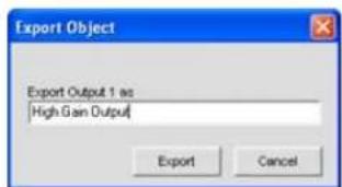
The object now appears in the Objects pane.
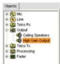
You can now drag and drop the object onto any channel of the same type to instantly apply the object's configuration settings to the channel.
NOTE: To apply the current channel settings to ALL channels of the same type without saving an object in the database, select Apply to all from the shortcut menu when right-clicking on the signal flow diagram. (Menu option not available for Telco/VolP rx or Telco/VolP tx
channels.)
To view detailed information about an AV device's configuration settings, or to create a custom AV device, use the AV Devices pane of the Database tab.
Advanced Configuration Objects
For advanced configuration tasks, Console allows you to create and apply Matrix Objects, Control Objects, Macro Objects, and Preset Objects as described in the following sections.
Matrix Objects
Matrix Objects allow you to save customized matrix configurations into the Database and reuse them. This enables you to instantly re-configure the entire matrix to accommodate changes in conferencing or venue configuration requirements, and to rapidly configure additional units using drag and drop configuration.
To capture the current matrix configuration and save it as a matrix object, right click anywhere in the center pane of the matrix screen and select Export as Object from the shortcut menu.
To apply a matrix object, drag it from the Objects Pane and drop it onto the matrix in the Matrix Tab screen.
Control Objects
Control Objects allow you to save control port objects into the Database. To capture the currently displayed control pin programming, right click in the Control/Status Pin Select portion of the Control Tab screen, and select Export as Object from the shortcut menu. After saving the control port object, it appears in the Objects pane on the right side of Console.
To apply a control object after saving it to the database, drag it from the Objects Pane and drop it onto the Control/Status Pin Select portion of the Control Tab screen.
Macro Objects
Macro Objects allow you to save macros into the Database and reuse them. To capture a macro and save it as an object, right click anywhere in the center pane of the macro screen and select Export as object from the shortcut menu. After saving a macro as an object, it appears in the Objects pane on the right side of Console.
To use a macro object, drag it from the Objects Pane and drop it onto the Macro Command List portion of the Macro Tab screen.
Preset Objects
Preset Objects allow you to save preset configurations into the Database and reuse them. This enables you to instantly apply preset changes, and to rapidly configure additional units using drag and drop configuration.
To capture the current preset and save it as an object, right click anywhere in the center pane of the preset screen and select Export as Object from the shortcut menu.
To apply a preset object, drag it from the Objects Pane and drop it onto the Site Pane of Console while in Console is in Preset Mode.
For additional information, refer to the Table of Contents for these related topics:
Database Tab•
Mic Input Settings
Line Input Settings•
Telco/VoIP rx Settings •
Telco/VoIP tx Settings •
Output Settings•
Processing Settings•
Fader Settings•
Matrix Tab•
Control Tab•
Macro Tab•
Preset Mode Overview•
PRESET MODE
Preset Mode allows you to create and modify presets. To execute presets, Console must be in Configuration Mode. There are 32 presets available in Console.
Presets provide the configuration flexibility needed to meet the challenges of changing conference room requirements. These changes include audio routing, gating, muting, levels, AEC referencing, and signal processing, as well as room combining and room configuration. Presets allow you to make configuration changes instantaneously—without interrupting or affecting any conferences in progress.
This topic covers:
Preset Configuration Tabs•
Creating Presets•
Executing Presets•
Preset Execution Flags•
Preset Control Masking
Preset Storage Space Considerations•
Exporting Preset Objects•
Accessing Preset Mode
To access Preset Mode, press the Preset button on the Console Button Bar, or select Preset from the Modes menu.
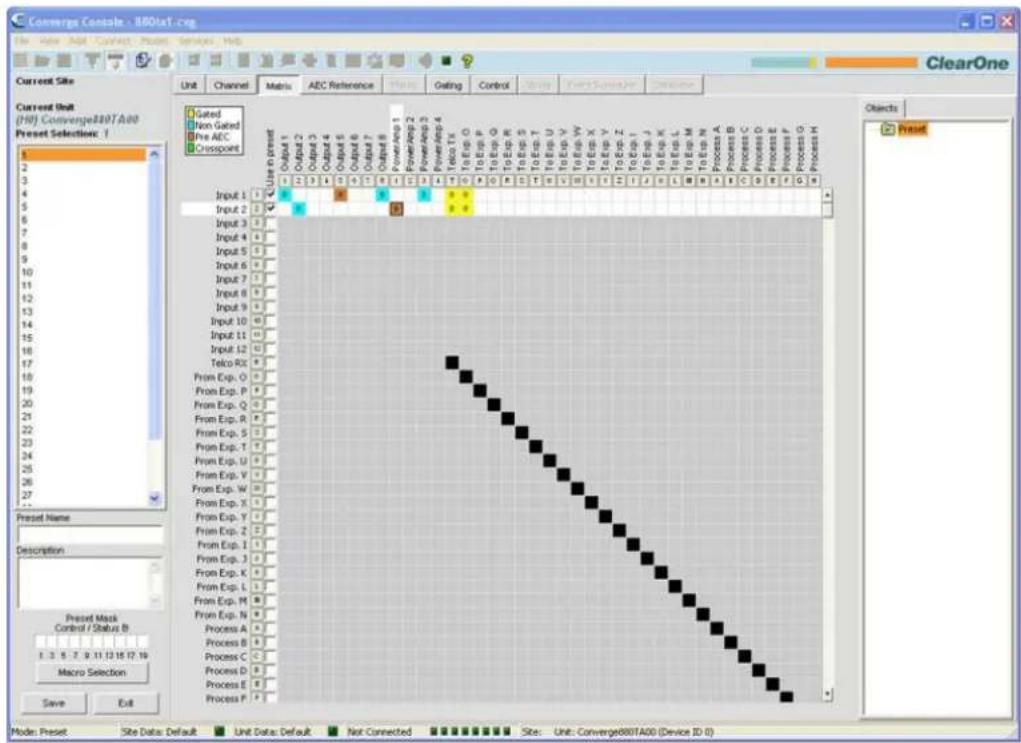
As shown above, Console displays the Matrix tab by default in Preset Mode (rather than the Unit tab that is the default in Configuration Mode). The Site Pane also changes to display the Current Site, Current Unit, Preset Selection list and the Preset Name, Description, and Preset Mask entry fields.
NOTE: Clicking a channel label in the matrix displays the Channel tab for the channel. Right-clicking anywhere in the matrix displays a shortcut menu that allows you to set a cross point, copy a cell, copy the matrix, paste a matrix, and clear the matrix.
Preset Configuration Tabs
In preset mode, the following tabs are available on the Console Tab Bar for defining preset configurations:
Unit Tab·
Channel Tab•
Matrix Tab·
AEC Reference/PA Adapt Reference Tab
Gating Tab·
Control Tab•
The channels available for configuration in a preset are determined by the channels selected in the Use in preset row on the matrix tab. Rows that are not selected in the matrix are grayed out, making them unavailable for preset configuration changes. In addition, only output channels that have a cross point set in the matrix tab will be available in the preset.
When you click a check box in the Use in preset row, the row becomes active and you can change its routing, gating, AEC/PA Adapt reference, and other settings. All changes will be saved in the preset and executed when the preset is ran. Channels that are not selected remain unchanged after preset execution.
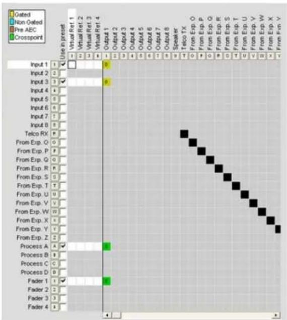
bar
| Event | Input | Output | Transitions | |---|---|---|---| | Input 1 | 1 | 0 | Non Oated | | Input 2 | 2 | 0 | Non Oated | | Input 3 | 3 | 0 | Non Oated | | Input 4 | 4 | 0 | Non Oated | | Input 5 | 5 | 0 | Non Oated | | Input 6 | 6 | 0 | Non Oated | | Input 7 | 7 | 0 | Non Oated | | Input 8 | 8 | 0 | Non Oated | | Telco RX | 9 | 0 | Non Oated | | From Exp. Q | 0 | 0 | Non Oated | | From Exp. P | 1 | 0 | Non Oated | | From Exp. Q | 0 | 0 | Non Oated | | From Exp. R | 0 | 0 | Non Oated | | From Exp. S | 0 | 0 | Non Oated | | From Exp. T | 0 | 0 | Non Oated | | From Exp. U | 0 | 0 | Non Oated | | From Exp. V | 0 | 0 | Non Oated | | From Exp. W | 0 | 0 | Non Oated | | From Exp. X | 0 | 0 | Non Oated | | From Exp. Y | 0 | 0 | Non Oated | | From Exp. Z | 0 | 0 | Non Oated | | Process A | 1 | 0 | Non Oated | | Process B | 1 | 0 | Non Oated | | Process C | 1 | 0 | Non Oated | | Process D | 1 | 0 | Non Oated | | Fader 1 | 1 | 0 | Non Oated | | Fader 2 | 1 | 0 | Non Oated | | Fader 3 | 1 | 0 | Non Oated | | Fader 4 | 1 | 0 | Non Oated | The chart displays the frequency of 'Output' and 'Transitions' for each event in the 'Telco TX' condition. The values for the 'From Exp.' series are not explicitly labeled but are inferred from the visual data points.In the example above, Input 1 and Input 3 are selected for use in the preset, and routed to Output 1 with gating enabled and a cross point level adjustment of zero. Cross points are also set for Output 1 on the Process A and Fader 1 channels.
For AEC/PA Adapt reference changes in a preset, you can also select channels in the Use in preset row as shown below. (Note that only the channels selected and cross pointed in the matrix are available, and that they are selected by default.)
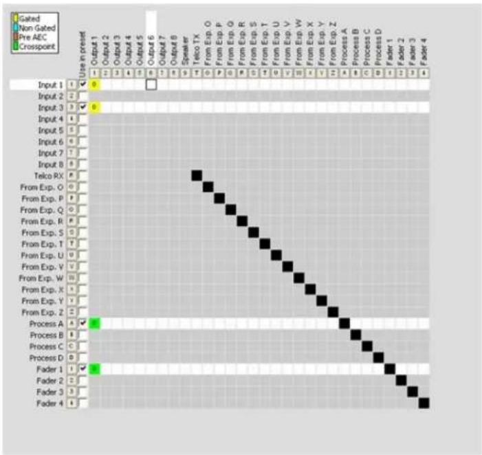
Creating Presets
Use the following procedure to create presets:
- Press the Preset Mode button on the Button Bar to put Console into preset mode.

- Select the number of the preset you want to configure in the Preset Selection list.
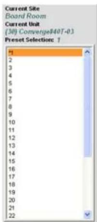
- Enter a Preset Name and Description in the entry fields (optional).
-
Select the channels you want to include in the preset using the Use in preset check boxes in the matrix.
-
Set the output channel cross points that you want to include in the preset using the matrix.
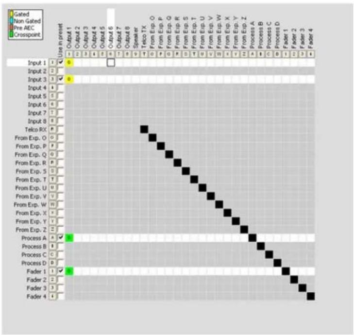
heatmap
| Input | Output | Gated | Non Gated | Pre AEC | Crosspoint | |---|---|---|---|---|---| | Input 1 | 1 | ✓ | ✓ | ✓ | ✓ | | Input 2 | 2 | ✓ | ✓ | ✓ | ✓ | | Input 3 | 3 | ✓ | ✓ | ✓ | ✓ | | Input 4 | 4 | ✓ | ✓ | ✓ | ✓ | | Input 5 | 5 | ✓ | ✓ | ✓ | ✓ | | Input 6 | 6 | ✓ | ✓ | ✓ | ✓ | | Input 7 | 7 | ✓ | ✓ | ✓ | ✓ | | Input 8 | 8 | ✓ | ✓ | ✓ | ✓ | | Telco RX | 9 | ✓ | ✓ | ✓ | ✓ | | From Exp. O | 0 | ✓ | ✓ | ✓ | ✓ | | From Exp. P | 1 | ✓ | ✓ | ✓ | ✓ | | From Exp. Q | 2 | ✓ | ✓ | ✓ | ✓ | | From Exp. R | 3 | ✓ | ✓ | ✓ | ✓ | | From Exp. S | 4 | ✓ | ✓ | ✓ | ✓ | | From Exp. T | 5 | ✓ | ✓ | ✓ | ✓ | | From Exp. U | 6 | ✓ | ✓ | ✓ | ✓ | | From Exp. V | 7 | ✓ | ✓ | ✓ | ✓ | | From Exp. W | 8 | ✓ | ✓ | ✓ | ✓ | | From Exp. X | 9 | ✓ | ✓ | ✓ | ✓ | | From Exp. Y | 10 | ✓ | ✓ | ✓ | ✓ | | From Exp. Z | 11 | ✓ | ✓ | ✓ | ✓ | | From Exp. A | 12 | ✓ | ✓ | ✓ | ✓ | | Process B | 13 | ✓ | ✓ | ✓ | ✓ | | Process C | 14 | ✓ | ✓ | ✓ | ✓ | | Process D | 15 | ✓ | ✓ | ✓ | ✓ | | Fader 1 | 16 | ✓ | ✓ | ✓ | ✓ | | Fader 2 | 17 | ✓ | ✓ | ✓ | ✓ | | Fader 3 | 18 | ✓ | ✓ | ✓ | ✓ | | Fader 4 | 19 | ✓ | ✓ | ✓ | ✓ | The chart displays a vertical grid of symbols (✓, □, ▢, ▣) representing the use in preset table for each input value. The legend indicates 'Gated', 'Non Gated', 'Pre AEC', and 'Crosspoint' categories. The values in the grid represent the frequency or count of occurrences for each input value within the output range. The color scale on the right indicates the magnitude of the occurrence of each input value within the output range. The data is presented in a single column format with rows and columns labeled 'Output' and 'Output'.-
Configure the desired setting changes for the preset including:
-
Mic Input, Line Input, Output, Telco/VoIP rx, Telco/VoIP tx, Processing, and Fader channel settings Gating settings
Control settings
AEC/PA Adapt Reference settings -
Click on the Preset Mask Control/Status B boxes to set the pin states (H = High, L = Low) required to trigger preset execution (optional). See Preset Control Masking for more information.
- Press the Macro Selection button to execute one or more macros when the preset executes (optional).
NOTE: In most cases, macros should not be used in a preset unless you want to run a serial command. Some examples that require a macro include querying device status when a preset executes, and sending a command string to an external control device to indicate preset/room configuration status. Also, macros execute at the end of a preset after all other routing, level, and configuration changes included in the preset are completed.
- Press the Save button to save the preset
- Click the Exit button to exit preset mode and return to configuration mode.
The preset is now available for execution as described below.
Executing Presets
There are five ways to execute presets:
Using Console in Configuration Mode1.
Using the LCD Preset Menu on the Front Panel2.
- Using control programming and external control devices (such as the closure contacts on a room partition) Using macros4.
Using serial commands via a Telnet session or via RS-2325.
NOTE: Presets only run on the current unit shown in the site pane. However, you can execute a preset on a unit connected to the Expansion Bus by using a macro.
Executing Presets Using Console
Select Execute Preset from the Services menu, or press the Execute Preset button on the button bar. Select the preset you want to execute from the Execute Preset dialog that appears, and press the Execute button.

NOTE: When executing presets in Console, the software assumes a preset execution flag value of 2, meaning that the preset executes and its execution state is set to off.
Executing Presets Using the LCD Preset Menu
Press the Select button on the front panel, use the Menu Dial to select Presets, and press the Select button.
The Preset Menu appears as shown below:
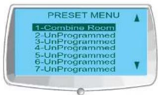
NOTE: When executing presets from the LCD Preset menu, Console assumes a preset execution flag value of 2, meaning that the preset executes and its execution state is set to off.
Use the following procedure to execute presets from the front panel LCD display:
- Use the Menu Dial to highlight the preset you want to execute
Press the 2. Select button
- Answer Yes at the prompt that appears to run the selected preset, or No to cancel.
Executing Presets Using Control Programming
Use the PRESET serial command in the Active (Low) Command or Inactive (High) Command fields in the Control Pin State section of the Control Tab. To execute multiple presets when a control condition is met, use the MACRO command to call a macro with multiple PRESET commands embedded, as explained in the next section.
For more information on PRESET and the complete Converge/Converge Pro serial command set, refer to Appendix A: Serial Commands.
Executing Presets Using Macros
Use the PRESET serial command to execute presets in a macro. To run multiple presets at the same time, use multiple PRESET commands in the macro. Macros can be executed from within Console or by using any external control device. Typically, you will create a macro for each room configuration (group of presets) that you want to execute at the same time.
Preset Execution Flags
Console uses user-selectable preset flags to determine the current execution state of a preset. This gives you complete control over preset execution, and allows you to combine multiple presets in a macro (or multiple macros) while ensuring that only the presets required for a given room configuration are executed when needed.
The three user-selectable execution flags are:
- 0 = do not execute the preset and set the execution state to off.
- 1 = check Preset state. If off, execute preset and set Flag to on. If on do nothing.
- 2 = ignore execution state. Execute the preset and set the execution state to off.
When an execution flag is set to on, the associated preset cannot be executed. Conversely, when it is set to off, the preset can be executed. To query the current execution flag state for a preset, use the PRESET command with the preset number and no other arguments.
Preset Control Masking
In traditional room-combining applications, one preset is created and executed for each room configuration. This can cause volume levels, mute states, and other channel configuration settings to reset for all room sections when a preset is executed. In addition, conferences in progress in unaffected room sections lose any custom settings, and the participants hear unnecessary pops and clicks.
Console eliminates these shortcomings through Preset Control Masking, which provides the following advantages:
• Automatic preset masking control when room dividers are wired to Control port B pins
Manual preset masking control via serial commands
Volume levels and mute states are reset only in sections that change
Unaffected room sections do not lose custom settings
Participants in unaffected room sections do not hear pops and clicks•
To use preset control masking, click on the Preset Mask Control/Status B boxes (located in the Site Pane while Console is in preset mode) to set the pin states (H = High, L = Low) required to trigger preset execution. You can use a pin state or combination of pin states to define when a preset will execute.
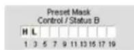
A typical use for preset masking is a room-combining application that uses automatic partitions with sensors that set the pin to high when a partition is open, and to low when a partition is closed. For example, if Pin 1 is connected to a first partition and Pin 3 is connected to a second partition, then the preset mask control/status B settings shown above would activate the preset when the first partition is open and the second partition is closed.
Preset Storage Space Considerations
In most preset configuration scenarios, it is unlikely that you would reach the storage capacity of a Converge/Converge Pro unit. In the event that you exceed the preset storage space, Console will alert you when you try to save the preset. You will be asked to reduce the number of cross point changes in the Matrix, or reduce the number of Macros in the preset. As a general rule, you make cross point changes to three-fourths of the matrix with up to two macros in a given preset; OR you can use up to 255 nested macros for a given preset.
Exporting Preset Objects
Preset objects allow you to save preset configurations into the Database and reuse them. This enables you to instantly apply preset changes, and to rapidly configure additional units using drag and drop configuration.
To capture the current preset and save it as an object, right click anywhere in the center pane of the preset screen and select Export as object from the shortcut menu.
To apply a preset object, drag it from the Objects Pane and drop it onto the Site Pane of Console while in Console is in Preset Mode.
For additional information, refer to the Table of Contents for these related topics:
Configuration Mode•
LCD Presets Menu•
Controls and Connections•
Expansion Bus Overview•
Unit Tab•
Channel Tab•
Matrix Tab•
AEC Reference/PA Adapt Reference Tab
Gating Tab•
Control Tab•
Macro Tab·
String Tab•
Database Tab•
Drag & Drop Configuration•
FILE MENU OVERVIEW
File Menu allows you to use Site Files and Print Reports.
Accessing the File Menu
In Console, select File from the menu bar. The File menu appears as shown below:
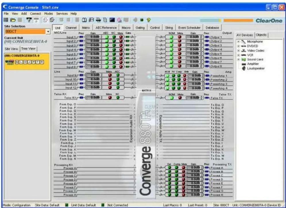
The File menu appears as shown below:
| File | View | Add | Connect |
| New Site | |||
| Open Site | |||
| Close Site | |||
| Save | |||
| Save As | |||
| Site Properties | |||
| 1 Board Room.cvg | |||
| 2 Site1.cvg | |||
| 3 Site1.cvg | |||
| Exit |
File menu options are explained in the following sections.
File Menu: Site Options
The File menu site options allow you to Create a New Site, open a saved site with Open Site, or close the current site with Close Site.
File Menu: Save Options
The File menu save options allow you to Save and Save As a site file.
File Menu: Print
Print allows you to create, view, print, and save Site and Unit configuration reports.
File Menu: Recent File List
The File menu recent file list displays the last four Site Files opened.
File Menu: Exit
The File menu Exit option closes Console. (To close the current Site without exiting Console, use the Close Site option.)
If you are Connected to a Site, a Confirm dialog appears when you select Exit as shown below.
Press Yes to confirm the exit or No to return to Console. Clicking Yes brings up another Confirm dialog as shown below.
Click Yes to save changes to the Site File, No to exit Console without saving changes, or Cancel to abort the exit and return to Console.
For additional information, refer to the Table of Contents for these related topics:
Site File Overview•
Print Reports
Create a New Site•
Connect To A Site•
Unit Properties•
PRINT REPORTS
The Print Reports option on the File menu allows you to print a configuration properties report for a Site or Unit.
Accessing Print Reports
To print a site or unit report, click on the File menu, select Print, then select Print Site Report or Print Unit Report as shown below.
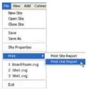
The Report window appears as shown below.
Report Window
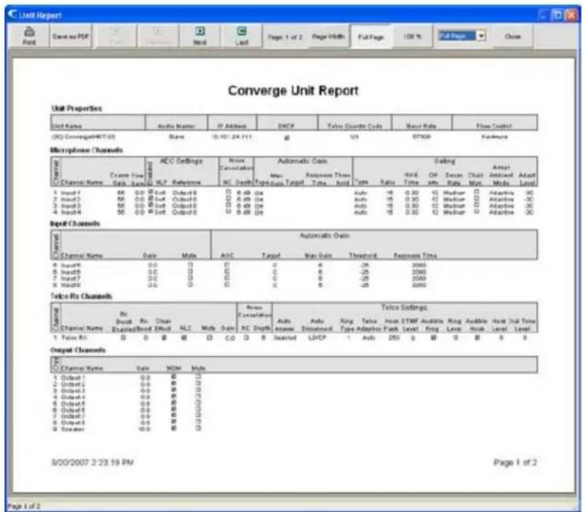
The report button bar provides buttons for viewing and printing the document, as well as saving the report to a PDF file. When you are finished viewing the report, click Close to close the report window and return to Console.
For additional information, refer to the Table of Contents for these related topics:
Site Properties•
Unit Properties•
VIEW MENU OVERVIEW
The View Menu provides an alternate navigation method for viewing the screens displayed by clicking on the Console Tabs.
Accessing the View Menu
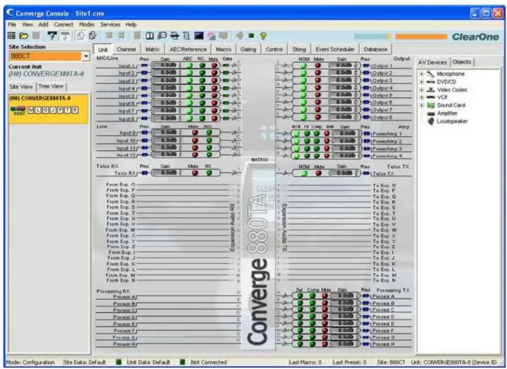
In Console, click View on the menu bar. The View menu appears as shown below:

A bullet indicates the view currently displayed in Console.
View Menu Options
Options available on the View menu include:
Unit View•
Channel View•
Matrix View•
AEC Reference Builder•
Macro Builder•
Gating Builder•
Control Builder•
Command Strings•
Event Scheduler•
Database Builder•
ADD MENU
The Add Menu allows you to add units to a site using default configuration settings.
Accessing the Add Menu
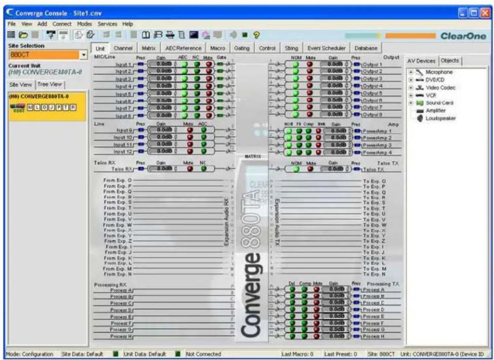
In Console, click Add on the menu bar. The Add menu appears as shown below:

Adding Units
On the Add menu, select the model you want to add to the site. The Unit Properties dialog appears as shown below:
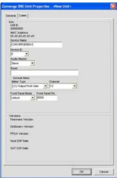
Configure the new unit's properties using the General tab. Configure the new unit's IP and serial port settings using the Comm tab. For more information on configuring unit properties, see Unit Properties.

flowchart
graph TD
    A["Input 1: MiO 1"] --> B["Pre Gain -36 dBu"]
    B --> C["Gain Coarse -56 dBu"]
    C --> D["Fine -20 dBu"]
    D --> E["Post Gain -20 dBu"]
    E --> F["Post Process -20 dBu"]
    F --> G["Post Gate -20 dBu"]

    H["PPWR"] --> I["-86 dBu"]
    I --> J["-61 dBu"]
    J --> K["-66 dBu"]
    K --> L["0.0 dB"]
    L --> M["-30 dBu"]
    M --> N["-30 dBu"]

    O["PA Adapt and AEC Reference Power Amp 4"] --> P["AEC"]
    P --> Q["NC"]
    Q --> R["Mute"]
    R --> S["Filter"]
    S --> T["AGC"]
    T --> U["ALC"]
    U --> V["Gate"]

    W["Input 1: Gated"] --> X["0"]
    X --> Y["0"]
    Y --> Z["0"]
    Z --> AA["0"]
    AA --> AB["0"]

    AC["Non Gated"] --> AD[Output 1: Output 2: Output 3: Output 4: Output 5: Output 6: Output 7: Output 8: Output 9: Output 10: PowerAmp 11: PowerAmp 12: PowerAmp 13: PowerAmp 14: PowerAmp 15: PowerAmp 16: PowerAmp 17: PowerAmp 18: PowerAmp 19: PowerAmp 20: PowerAmp 21: PowerAmp 22: PowerAmp 23: PowerAmp 24: PowerAmp 25: PowerAmp 26: PowerAmp 27: PowerAmp 28: PowerAmp 29: PowerAmp 30: PowerAmp 31: PowerAmp 32: PowerAmp 33: PowerAmp 34: PowerAmp 35: PowerAmp 36: PowerAmp 37: PowerAmp 38: PowerAmp 39: PowerAmp 40: PowerAmp 41: PowerAmp 42: PowerAmp 43: PowerAmp 44: PowerAmp 45: PowerAmp 46: PowerAmp 47: PowerAmp 48: PowerAmp 49: PowerAmp 50: PowerAmp 51: PowerAmp 52: PowerAmp 53: PowerAmp 54: PowerAmp 55: PowerAmp 56: PowerAmp 57: PowerAmp 58: PowerAmp 59: PowerAmp 60: PowerAmp 61: PowerAmp 62: PowerAmp 63: PowerAmp 64: PowerAmp 65: PowerAmp 66: PowerAmp 67: PowerAmp 68: PowerAmp 69: PowerAmp 70: PowerAmp 71: PowerAmp 72: PowerAmp 73: PowerAmp 74: PowerAmp 75: PowerAmp 76: PowerAmp 77: PowerAmp 78: PowerAmp 79: PowerAmp 80: PowerAmp 81: PowerAmp 82: PowerAmp 83: PowerAmp 84: PowerAmp 85: PowerAmp 86: PowerAmp 87: PowerAmp 88: PowerAmp 89: PowerAmp 90: PowerAmp 91: PowerAmp 92: PowerAmp 93: PowerAmp 94: PowerAmp 95: PowerAmp 96: PowerAmp 97: PowerAmp 98: PowerAmp 99: PowerAmp 100: NOM (NOM)
    X --> Y
    Y --> Z
    Z --> AA
    AA --> AB
    AB --> AC
    AC --> AC
    AC --> AD
    AD --> AE
    AE --> AF
    AF --> AG
    AG --> AH
    AH --> AI
    AI --> AJ
    AJ --> AK
    AK --> AL
    AL --> AM
    AM --> AN
    AN --> AO
    AO --> AP
    AP --> AQ
    AQ --> AR
    AR --> AS
    AS --> AT
    AT --> AU
    AU --> AV
    AV --> AW
    AW --> AX
    AX --> AY
    AY --> AZ
    AZ --> BA
    BA --> BB
    BB --> BC
    BC --> BD
    BD --> BE
    BE --> BF
    BF --> BG
    BG --> BH
    BH --> BI
    BI --> BJ
    BJ --> BK
    BK --> BL
    BL --> BM
    BM --> BN
    BN --> BO
    BO --> BP
    BP --> BPB
    BPB --> BPCC
    BPCC --> BPCCB
    BPCCB --> BPCCD
    BPCCD --> BPCCE
    BPCCE --> BPCCF
    BPCCF --> BPCCG
    BPCCG --> BPCCH
    BPCCH --> BPCCI
    BPCCI --> BPCCJ
    BPCCJ --> BPCCK
    BPCCK --> BPCCL
    BPCCL --> BPCCL1
    BPCCL1 --> BPCCL2
    BPCCL2 --> BPCCL3
    BPCCL3 --> BPCCL4
    BPCCL4 --> BPCCL5
    BPCCL5 --> BPCCL6
    BPCCL6 --> BPCCL7
    BPCCL7 --> BPCCL8
    BPCCL8 --> BPCCL9
    BPCCL9 --> BPCCL10
Press OK to add the unit to the site or Cancel to return to Console. The added unit appears on the Site View tab of the Site pane, highlighted in orange as shown below:
NOTE: The Status bar at the bottom of the Console window displays the current status of the unit and the site. As shown above, site data errors and unit data errors are indicated by magenta and red LEDs respectively. Complete unit configuration with correct settings to clear the errors. When correct configuration is complete, the status LEDs will change to green. The Status bar also displays Last Macro and Last Preset.
For more information, refer to the Table of Contents for these related topics:
Unit Properties
Create A New Site•
Connect To A Site•
Site Properties•
Unit Tab•
Configuration Mode Overview•
CONNECT MENU OVERVIEW
The Connect Menu enables you to connect to a site, disconnect from a site, and refresh the current display for a site. Connecting to a site allows you to control and configure the units in that site. See Site Setup Overview for more information.
Accessing the Connect Menu
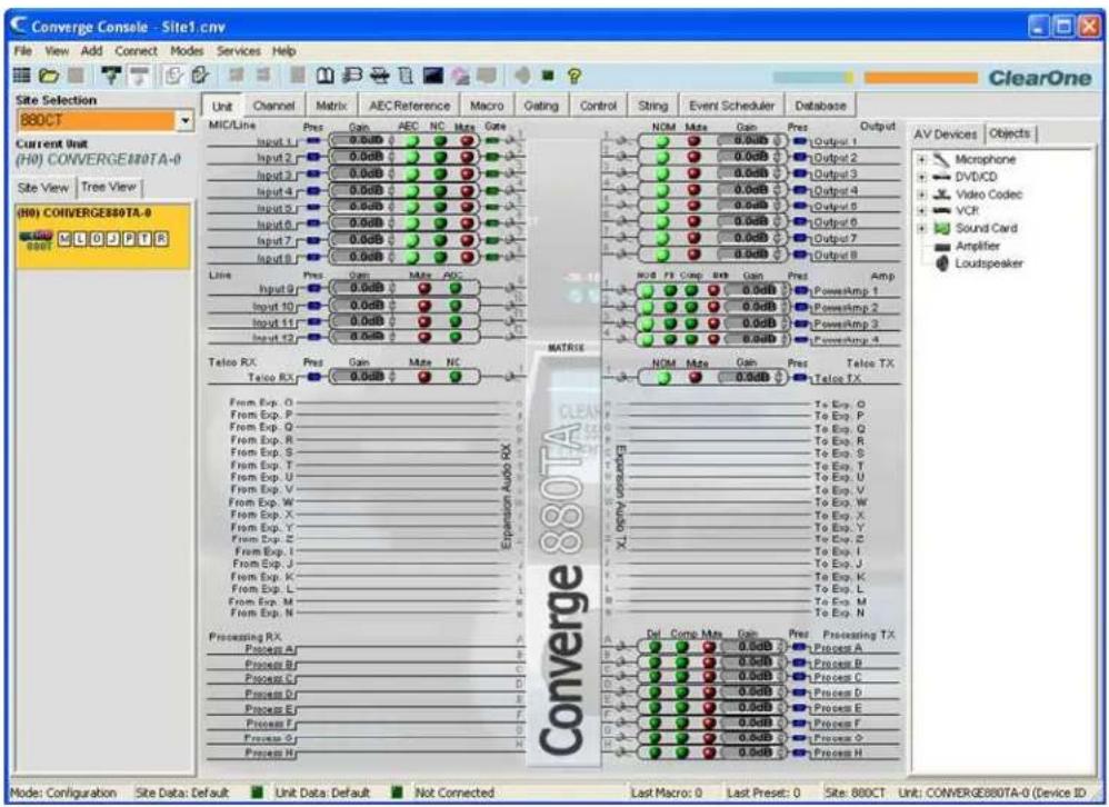
In Console, select Connect from the menu bar. The Connect menu appears as shown below:
Connect Menu Options
Connect• : Connects to a site via USB or IP.
- Disconnect: Disconnects Console from the currently connected site. (This option is not available if no site is connected.)
For additional information, refer to the Table of Contents for these related topics:
Site Setup Overview
Connect To A Site•
Create A New Site•
MODES MENU OVERVIEW
The Modes Menu allows you to switch Console between Configuration Mode and Preset Mode. Configuration Mode allows you to configure a wide range of advanced settings for all models. Preset Mode allows you to create presets for specific venues and apply them to instantly to a unit.
Accessing the Modes Menu
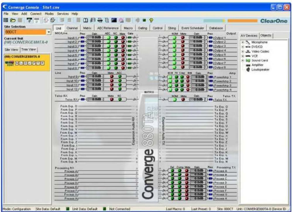
In Console, select Modes from the menu bar. The Modes menu appears as shown below:
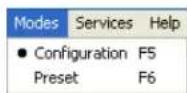
A bullet indicates the current mode. To switch modes, select Configuration or Preset. Console immediately reflects mode changes.
NOTE: You can also switch modes using the 📄 buttons on the Console Button Bar.
For additional information, refer to the Table of Contents for these related topics:
Configuration Mode
Preset Mode·
Console Button Bar•
SERVICES MENU OVERVIEW
The Services Menu provides various utilities for using and managing Converge/Converge Pro units.
Accessing the Services Menu
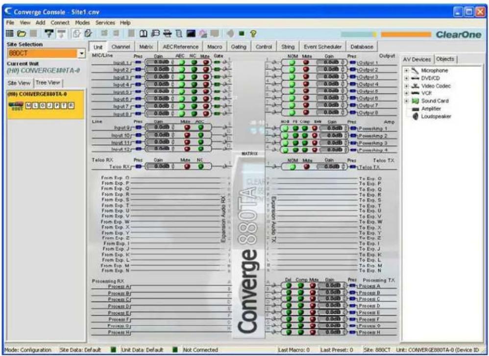
In Console, click Services on the menu bar. The Services menu appears as shown below:
| Services | Help |
| Dialer | |
| Phonebook | |
| Label Editor | |
| Device Log | |
| Event Log | |
| Web Builder | |
| Firmware Loader | |
| Debug Console | |
| System Checks | |
| Execute Preset | |
| Run Macro |
Service Menu Options
Options available on the Services menu include:
Dialer•
Phonebook•
Label Editor•
Device Log•
Event Log•
Firmware Loader•
DIALER
The Dialer provides a software telephone interface for teleconferencing applications.
NOTE: Dialer is only available when Console is connected to a site.
Accessing Dialer
To access the dialer, select Dialer from the Services menu; press the Dialer button on the Console Button Bar; or press the Dialer button in the Telco Rx or Telco Tx channel screens.
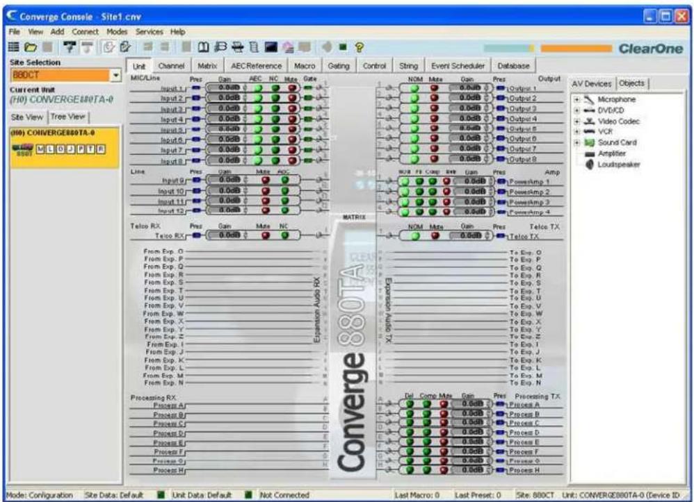
Using Dialer
When using the dialer, the date and time, number dialed, and call status are displayed in the LCD section of the dialer window.
![Dialer MUTE MUTE RE_NULL 2/12/2007 1:47:17 PM [idle] PhoneBook ClearOne ON/OFF REDIAL FLASH 1 ABC DEF CLEAR 4 GHI JKL MNO 7 PQRS TUV WXYZ * 0 # PHONEBOOK Close](/content/2026/05/777819/images/7daecdc9bf62bc2c5ff9d88acea9b57d70c8a0fcf5a7faaf96f599230ec3d446.jpg)
Placing and Ending Calls
To place a call, select a number from the Phonebook section of the dialer window, or manually enter a number, then press the ON/OFF hook button.
You can also access the Phonebook by pressing the PHONEBOOK button.
To end a call, press the ON/OFF hook button.
To redial a number, press the REDIAL button.
Using Line Features
Use the FLASH button to access telco and PBX line features.
Muting
Use the MUTE Tx and MUTE Rx buttons to mute the transmit and receive signals respectively when a call is in progress.
Renulling the Line
During conference calls, line conditions and other factors can cause divergence in the automatic Telephone Echo Cancellation (TEC) adaptation process. If side tone occurs during a conference call, press the RE_NULL button to send a short burst of white noise over the line and initiate TEC readaptation (Not supported in VoIP functionality).
NOTE: Renulling the line sends a burst of white noise that will be audible on the far end of the telephone line.
For more information, please see the Table of Contents for these related topics:
Connect To A Site•
Services Menu Overview•
Telco/VoIP rx Settings •
Telco/VoIP tx Settings •
Phonebook•
Telephone Echo Cancellation•
PHONEBOOK
The Phonebook allows you to store telephone numbers and make speed-dial assignments for teleconferencing applications.
Accessing Phonebook
To access the phone book, select Phonebook from the Services menu; press the Phonebook 📄 button on the Console Button Bar; or press the Phonebook button in the Dialer screen.
![Dialer MUTE MUTE RE_NULL 2/12/2007 1:47:17 PM [idle] 1 ABC DEF CLEAR ClearOne 4 5 6 GHI JKL MNO ON/OFF REDIAL 7 8 9 FLASH * 0 # PHONEBOOK PHONEBOOK Close](/content/2026/05/777819/images/bbaf7eb2e7467e4b044ffb13725a68f090ace68b3c0ef773898585c3d713c61b.jpg)
Using Phonebook
To add an entry to the phonebook, press the New Entry button; enter a Name and Number; and select a Speed Dial Number (optional).
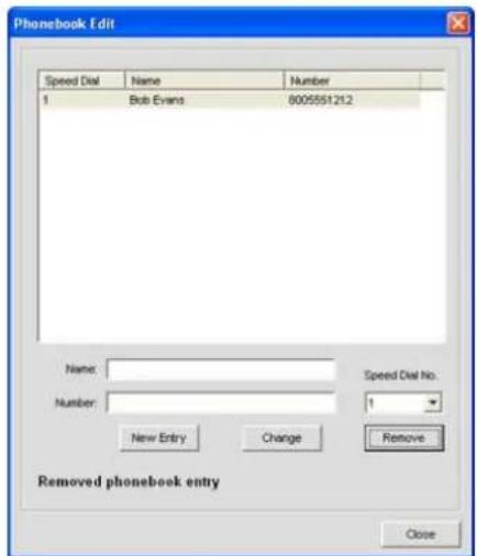
NOTE: The Number field allows numbers, #, and * only. No other characters (such as parentheses and dashes) are allowed.
Press the Add button to add the entry to the phonebook. The number now appears in the phonebook list, and in the Phonebook portion of the Dialer screen.

To edit an entry, select it and press the Change button. To delete an entry, select it and press the Remove button.
For additional information, please refer to the Table of Contents for these related topics:
Dialer•
Button Bar•
Services Menu Overview•
LABEL EDITOR
The Label Editor allows you to quickly change the names (labels) assigned to units and channels. Using descriptive names makes it easier to identify units and channels for configuration and management purposes. Label changes are global, and appear throughout Console wherever the label is referenced.
In addition to using the label editor to rename objects, you can use the label entry fields provided throughout Console.
Accessing Label Editor
To access the label editor, select Label Editor from the Services menu, or click the Label Editor button on the Converge Button Bar.
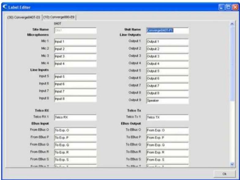
Using Label Editor
As shown above, the label editor contains one tab for each unit in the currently connected site. To modify a label, select the unit tab and click on the entry field for the object name that you wish to change. When finished, click the Ok button to save the changes and close the label editor window.
For additional information, please refer to the Table of Contents for these related topics:
Services Menu Overview•
Mic Input Settings•
Line Input Settings•
Telco/VoIP rx Settings •
Output Settings•
Telco/VoIP tx Settings •
Processing Settings•
Fader Settings•
DEVICE LOG
The Device Log captures device events for administration, configuration, and troubleshooting purposes.
NOTE: The device log can store 256K bytes of data. Once this limit is reached, the first 128K of data is truncated and logging resumes.
Accessing Device Log
To access the device log, select Device Log from the Services menu, or click the Device Log button on the Console Button Bar.

Using Device Log
In the Device Log window, select the events you want to log using the Event Selection check boxes.
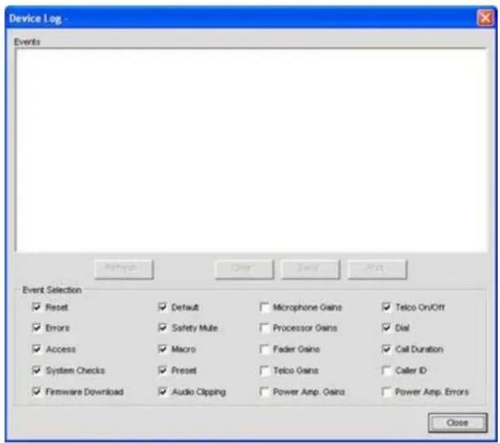
Events available for logging include:
Reset• : Reports unit reset events
Errors• : Reports internal unit errors
Access: • Reports all web, Telnet, front panel, and USB access events
System Checks• : Reports the pass/fail status of System Checks
Firmware Download • : Reports firmware downloads
Default• : Reports unit default events
Safety Mute• : Reports safety mute events
Macro• : Reports Macro execution events
- Preset: Reports when Presets are run
• Audio Clipping: Reports audio clipping events - Telco On/Off: Reports when the telco line goes on or off hook
• Dial: Reports dial command events including DTMF, Phonebook, Speed Dial, and Redial - Call Duration: Reports the time between on and off hook events for all calls
- Microphone Gains: Reports microphone gain levels
- Processor Gains: Reports processor gain levels
• Fader Gains: Reports fader gain levels
• Telco Gains: Reports telco gain levels
• Power Amp. Gains: Reports power amp gain levels - Caller ID: Shows Caller ID report
• Power Amp. Errors: Reports power amp errors
NOTE: All device events and Event Scheduler events are logged automatically.
Use the Refresh, Clear, Save, and Print buttons to refresh the log display, clear the log, save the log to a text file, and print the log.
For additional information, please refer to the Table of Contents for these related topics:
Site Properties•
System Checks•
Firmware Loader•
Console Overview•
LCD Settings Menu•
Macro Tab•
Preset Mode Overview
Execute Presets•
Dialer•
Phonebook•
EVENT LOG
The Event Log captures Console events for administration and troubleshooting purposes. Event types captured include failed login attempts, site disconnects, unit reboots, socket time outs, internal system errors, and serial command execution errors.
Accessing Event Log
To access the event log, select Event Log from the Services menu, or click the Event Log button on the Console Button Bar.

Using Event Log
Captured events appear in the left section of the Event Log window. Event Codes and Messages appear in the right section of the window.
![Event Log Time Message 3/9/2007 11:16:25 AM [ Unit 7 ] Invalid Unit Values 3/9/2007 11:20:53 AM User Initiated Disconnect 3/9/2007 11:23:07 AM Remote socket timed out. 3/14/2007 3:21:00 PM Remote Connection Closed 3/20/2007 5:00:19 PM Remote socket timed out. 3/22/2007 2:58:47 PM Remote Connection Closed 3/27/2007 11:45:34 AM User Initiated Disconnect 3/27/2007 12:23:00 PM User Initiated Disconnect 4/2/2007 1:33:39 PM Login attempt failed! 4/11/2007 1:02:42 PM Login attempt failed! 5/1/2007 3:23:21 PM [ #30 PHONEBOOKADD-1 Test ] Event Code -110 Message [ Unit 7 ] Invalid Unit Values Print Clear Ok](/content/2026/05/777819/images/1bcaa0dbf20f51816a500d95410692fda900194cacf26abff7b692bdb5ed9e4a.jpg)
To print the event log, press the Print button. To clear the event log, press the Clear button and answer Yes to the confirmation dialog that appears.
For additional information, please refer to the Table of Contents for these related topics:
Services Menu•
Event Scheduler•
WEB BUILDER
Web Builder consists of User Console and Control Console. These consoles allow you to configure a subset of call management and mixing features for access through a web portal integrated into the firmware. The web portal can be accessed over IP with Microsoft's Internet Explorer (requires IE version 5.5 or later and Sun Microsystems Java Runtime Environment version 6.0 or higher).
User Console allows you to configure basic call functions, including on/off hook, redial, volume, and mute, for up to two units. Control Console allows you to perform basic channel and mixing configuration tasks for all units.
Accessing Web Builder
To access the web builder, select Web Builder from the Services menu, or press the Web Builder button on the Console Button Bar.
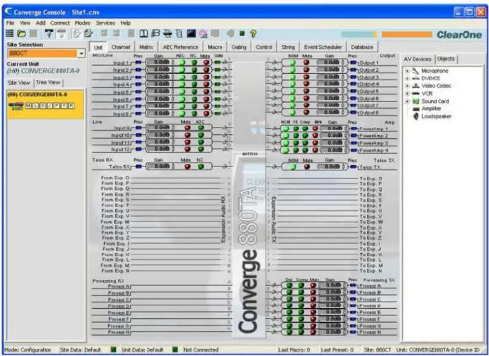
Configuring User Console
The User Console tab allows you to configure the web version of Dialer, a software interface that emulates the functionality of Clearone's Tabletop Controller. User Console provides six user-programmable keys as described in the following sections.
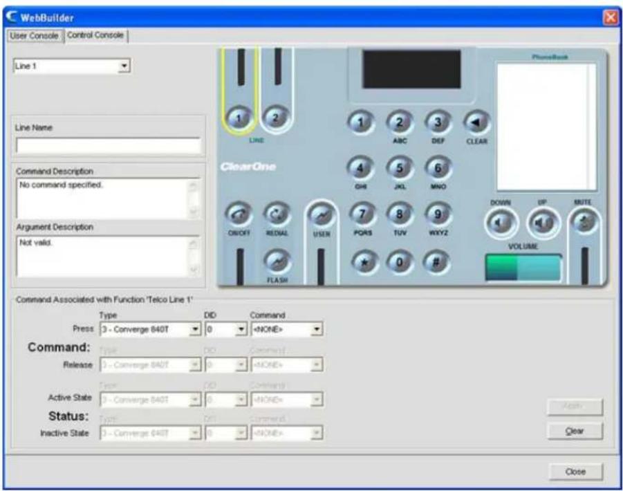
Select the key you want to program from the drop-down list in the upper left hand corner of the screen. Programmable keys include:
Line 1·
Line 2·
User•
Volume Down•
Volume Up•
Mute•
If you are configuring a Line or User button, enter a name for it in the Line (or User) Name field (optional).
The key selected determines the commands available in the Command drop-down lists in the Command section of the screen.

For example, the commands available for the volume buttons include GAIN, MACRO, and RAMP. When you select a command, the configurable parameters for that command appear as shown above. (For more information on the command editor, see Command Editor in the Control Tab topic.)
Select the Type, DID (device ID), and Command from the drop-down lists. After selecting a command and configuring its parameters, press the Apply button to save the button programming. To clear a command, press the Clear button.
For some commands, such as MACRO, the Status section of the command editor becomes active. Status controls the LED status indicator for the associated button based on the state conditions entered in the Active State (LED on) and Inactive State (LED off) rows of the Status section.
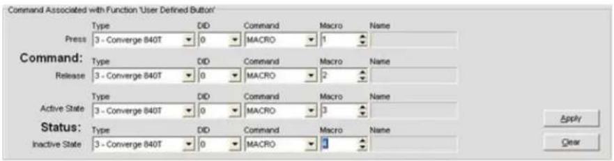
Pressing a programmed button in the Web Portal executes the command selected in the Press row of the Command section. Releasing a button executes the command selected in the Release row (if applicable for the programmed command).
Configuring Control Console
Control Console provides eight fader groups (mixers) with gain sliders, mute buttons, and level meters. It also provides four user-programmable buttons. The fader groups can control multiple units in a site.
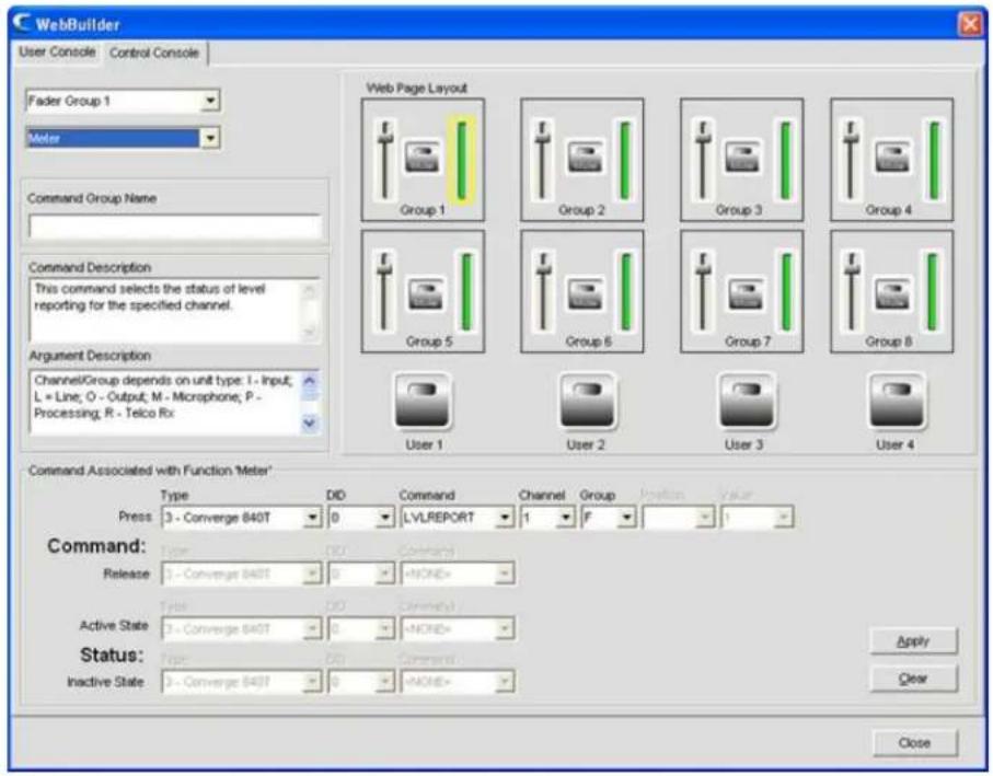
Select the fader group or user key you want to program from the drop-down list in the upper left hand corner of the screen. For fader groups, you will also need to select Gain, Mute, or Meter from the second drop-down list.
NOTE: You can also select an element to program, such as a gain slider or user button, by selecting its graphical representation in the Control Console window. For example, in the screen shot above, the meter element for Fader Group 1 is selected. The LVLREPORT command associated with the meter will display real-time level of fader group on the Converge Pro 840T unit (DID 0).
The element selected determines the commands available in the Command drop-down lists in the Command section of the screen.
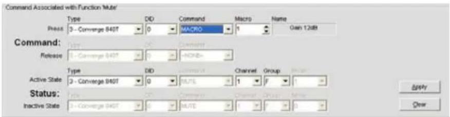
For example, the commands available for the mute buttons include MACRO and MUTE. When you select a command, the configurable parameters for that command appear as shown above. (For more information on the command editor, see Command Editor in the Control Tab topic.)
Select the Type, DID (device ID), and Command from the drop-down lists. After selecting a command and configuring its parameters, press the Apply button to save the button programming. To clear a command, press the Clear button.
For some commands, such as MACRO, the Status section of the command editor becomes active. Status controls the LED status indicator for the associated button based on the state conditions entered in the Active State (LED on) and Inactive State (LED off) rows of the Status section.
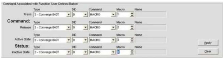
Changing the settings of a fader group element, or pressing a programmed button in the Web Portal executes the command selected in the Press row of the Command section. Releasing a button executes the command selected in the Release row (if applicable).
Accessing the Web Portal
After programming User Console and Control Console, you can access them using the Web Portal to monitor and manage audio conferences.
User access privileges to these web-based management tools are as follows:
Administrator• : Full web access.
- Manager: Web access to Dialer, Maintenance, Registration, About, and Help pages.
- User: Web access to the Dialer, Registration, About, and Help pages.
To open the web portal, enter the IP address of the unit you want to connect with. The web portal appears as shown below.
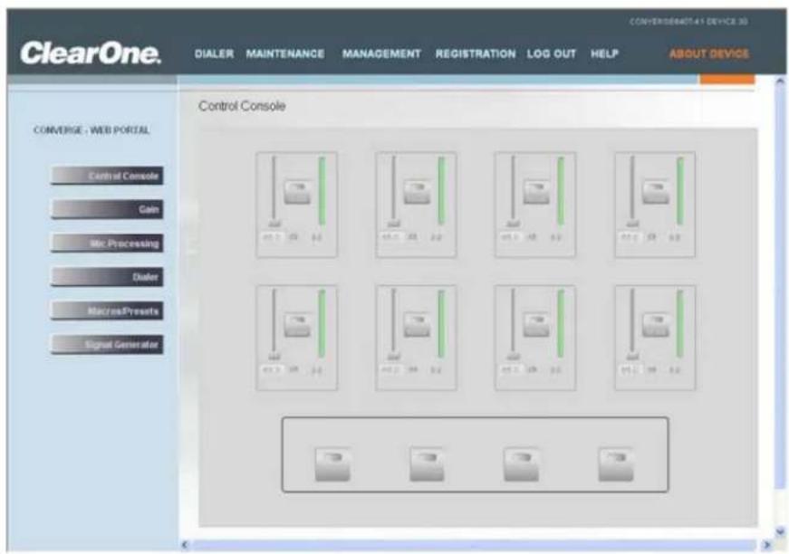
To access programmed call management functions, click on DIALER. To access programmed control console mixing functions, click on MANAGEMENT (shown above).
For additional information, please refer to the Table of Contents for these related topics:
Dialer•
Phonebook•
Macro Tab•
Mic Gating•
Mic Input Settings•
Line Input Settings•
Telco/VoIP rx Settings •
Telco/VoIP tx Settings •
Output Settings
Matrix Tab·
FIRMWARE LOADER
Firmware Loader allows you to upgrade firmware when ClearOne releases enhancements. All models use the same firmware file (converge.mdo). When upgrading firmware, all units in the site are automatically updated simultaneously.
NOTE: Before upgrading firmware, save a copy of your site files using the Save or Save As options on the File menu. When upgrading from Converge Console 1.0.4 or 1.1.5 to 2.0.x or 3.0.x the Firmware must be updated twice.
Accessing Firmware Loader
To load firmware, click on the Services menu select Firmware Loader. The Converge Firmware Loader window appears as shown below.
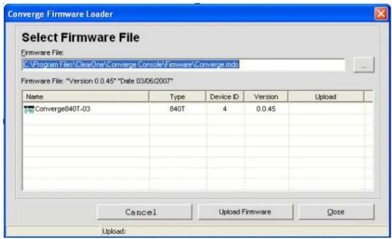
Loading Firmware
Firmware Loader automatically looks for firmware files in the default Converge Console directory.
Press the ⋯ button to locate firmware files stored in a different directory, or enter an explicit file path into the Firmware File entry field. All available firmware files in the chosen directory are displayed in the firmware file table.
Once you have located the firmware file you want to load, select it from the firmware file table and click Upload Firmware. A warning dialog appears (shown below). Click Yes to proceed with the firmware upload.
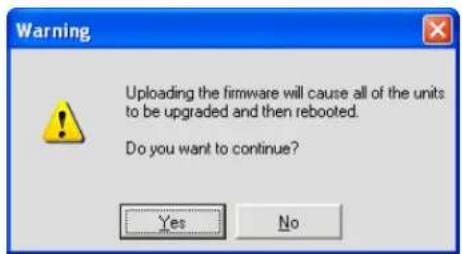
The upload begins, and the Firmware Loader displays progress in the Upload column of the firmware file table, and in the Status Bar at the bottom of the window as shown below:

In addition, the LED indicators on the status bar in Console turn yellow to indicate the firmware load is in progress as shown below:
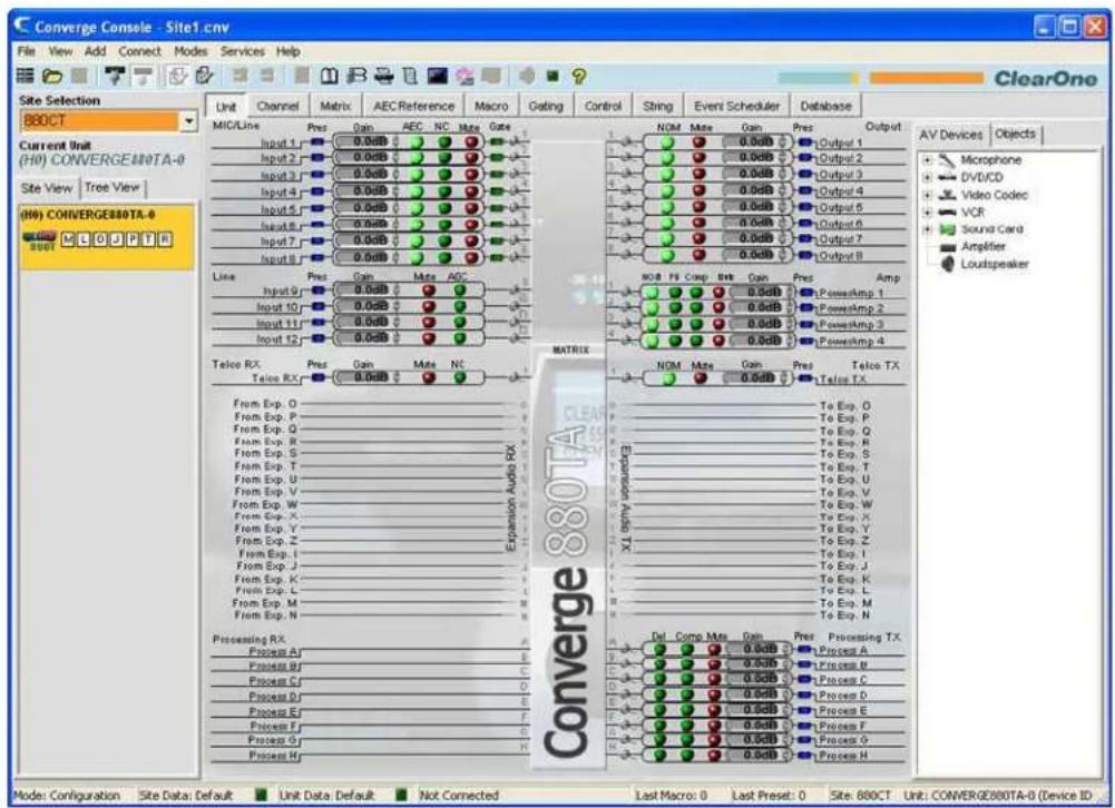
When the firmware load is complete, the unit reboots. The unit now has the selected firmware file loaded.
If you experience problems with firmware loads, please contact ClearOne Technical Support.
For additional information, please refer to the Table of Contents for these related topics:
Configure Unit Properties•
Configuration Mode Overview
Customer Service and Support•
DEBUG CONSOLE
The Debug Console provides five tabs for monitoring system performance, testing and troubleshooting audio performance, and running system diagnostics:
Meter View•
Gate View•
Signal Generator•
System Checks•
System Check Config•
Accessing Debug Console
To access the debug console, select Debug Console from the Services menu, or press the Debug Console button on the Console Button Bar.

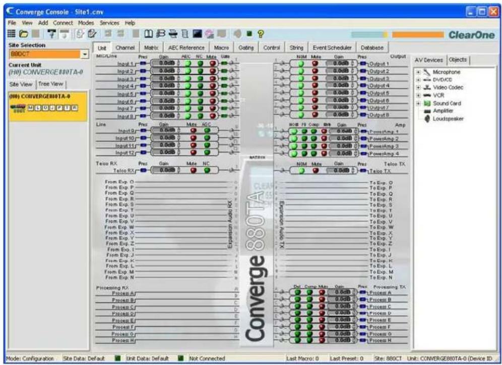
Debug console tabs are described in the following sections.
Meter View Tab
The Meter View tab provides eight user-configurable level meters for monitoring signal levels on any channel in a site.
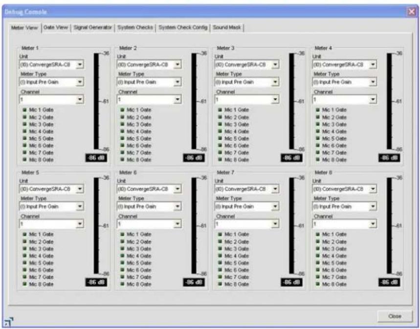
To configure a meter, select the Unit, Meter Type, and Channel using the drop-down lists. Meter view provides a useful diagnostic tool for system-wide troubleshooting and configuration.
Gate View Tab
The Gate View tab shows real-time gating status, allowing you to monitor gating activity for the mics and gating groups for the currently connected unit.
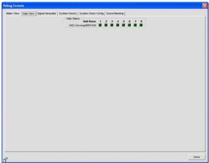
The gate indicator for each input is dark green in the gate-off condition and light green if the input is gated on.
Signal Generator
The Signal Generator tab enables you to generate test signals to audibly test signal paths, gain settings, routing, and channel configuration settings. The signal generator can also be used for noise masking in courtroom, clergy, and corporate applications.
NOTE: When the signal generator is on for any unit in the site, the Signal Generator LED on the Console Button Bar flashes green.

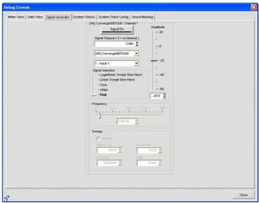
Test Signal Types
The signal generator provides three types of test signals: Pink, White, and Tone.
- Pink Noise: A test signal containing all the frequencies in a given audio spectrum, with equal energy in each octave. Pink noise is the default signal.
- White Noise: A test signal with equal energy distribution throughout a given frequency range.
- Tone: A sine-wave test signal with less than .03% distortion. Selecting Tone with the Signal Selection slider activates the Frequency configuration section of the tab.
- Linear Sweep Sine Wave: A test signal increasing in frequency using predefined steps.
- Log Sweep Sine Wave: A test signal increasing in frequency using exponential steps (rises on a curve).
Running a Signal Test
Use the following procedure to run a signal test:
Select the unit and channel to test using the unit and channel drop down lists.1.
- Select the type of test tone using the Signal Selection slider.
- Select the amplitude (volume) of the test tone using the Amplitude slider. The amplitude range is from -60 to +20dB. The default is -20dB.
- Set the level for the test tone using the dB entry field or up/down arrows.
- Set desired test tone duration using the Signal Timeout entry field.
- For Tone signals, set the additional Frequency settings as explained in the next section.
- Press the Signal On button to initiate the test signal on the selected unit and channel. The signal will
continue using the specified settings until the Signal Timeout is reached, or the Signal On button is pressed again, whichever occurs first.
Tone Frequency Settings
Configure Frequency settings for tone tests as follows:
- Select a tone frequency using the Frequency slider, or enter a frequency in the entry box.
- Alternatively use the Auto Sweep button to sweep a range of frequencies using the Begin Frequency, End Frequency, Increment, and Rate settings. Select the Repeat checkbox if you want the sweep to continue in cycles.
NOTE: Use auto sweep to test the frequency response of a room and speakers, and to identify distortion or rattles produced by the speakers or speaker housings. Auto sweep moves the frequency of the signal generator from a low frequency to a high frequency at the specified rate. The Frequency slide control and readout reflect progress while the sweep is in progress. Sweep range is 20Hz—20kHz; increment range is 1Hz—20kHz, and the rate range is 10ms—2000ms. The default rate is 100ms.
- Press the Signal On button to generate the tone test signal, or press the Auto Sweep button to initiate an auto sweep.
System Checks Tab
System Checks enable you to test network connections, telephone connections, microphones, and output channels for all units in a site. Running system checks can help identify component failures within the system using the tests you select on the System Check Config tab (described in the next section).
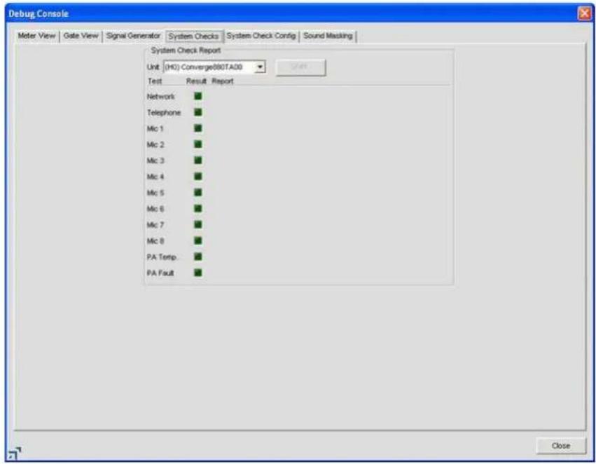
The test LEDs indicate test results as follows:
Red • = Test fails
Yellow• = Test not enabled in System Check Config
Green• = Test passes
System Check Config Tab
The System Check Config tab allows you to select and configure the diagnostic tests run on System Checks tab.
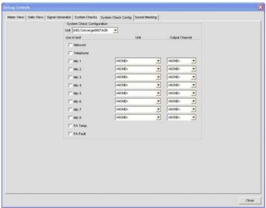
System Check Config settings include:
- Unit (System Check Configuration): Specifies the unit in the site that you want to test.
• Network: Select this check-box to test the IP configuration and network connectivity for the selected unit. - Telephone: Select this check box to test Telco/VoIP rx and/or Telco/VoIP tx functionality.
- Mic 1-4 (840T), Mic 1-8 (880, 880T, 880TA, 8i, SR 1212, SR 1212A): Select the check box(es) for the mic input channels that you want to test.
- Unit: Specifies the unit that will provide test audio to the speaker.
- Output Channel: Specifies the output channel that will provide test audio to the speaker.
System Check Configuration - VH20
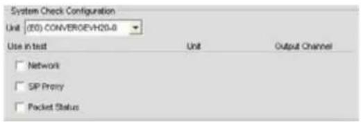
• Network: Select this check-box to test the IP configuration and network connectivity for the selected unit.
- SIP Proxy: Select this check box to test the Proxy 1 and 2 registration status
- Packet Status: Select this check box to the for packet loss
Select the tests you want to run using the Use in test check boxes, and select the unit(s) and output(s) (with speakers connected) using the Unit and Output Channel drop-down lists. Execute the selected tests by pressing the Start button on the System Checks tab.
Sound Masking Tab
Sound Masking is an Amplifier Out only feature consisting of three modes:

Off• : Disables the feature.
• Voice: Masking operates only in the range usually used when the target audio is vocal.
- Wideband: Masking operates throughout the audible range of the unit.
For additional information, please refer to the Table of Contents for these related topics:
Device Log•
Event Log
Mic Input Settings•
Line Input Settings•
Telco/VolP rx Settings •
Telco/VoIP tx Settings •
Output Settings•
Processing Settings
- Fader Settings
- Matrix Tab
EXECUTE PRESETS
The Execute Presets command on the Services menu allows you to run presets while Console is in Configuration Mode.
NOTE: This command is not available while Console is in Preset Mode.
Accessing Execute Presets
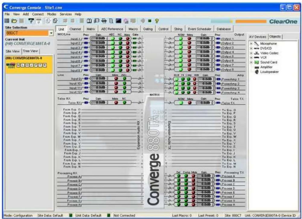
From the Console main screen, click on the Services menu and select Execute Preset as shown below.
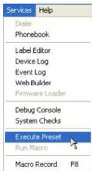
The Execute Preset dialog appears as shown below.
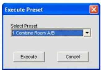
Select the preset you want to run from the drop-down list, then click Execute to run the preset or Cancel to return to Console. You can also use macros to execute presets or multiple presets simultaneously. For more information, see the Macro Tab topic.
For additional information, please refer to the Table of Contents for these related topics:
Preset Mode•
Services Menu•
Configuration Mode•
Preset Mode Overview•
Macro Tab·
APPENDIX A: APPLICATION PROGRAMMER'S INTERFACE
TYPE AND DEVICE IDS
Converge/Converge Pro Device Types and Device IDs by model are as follows:
| Model Device Type Device ID Range | ||
| 880 1 0-B | ||
| TH20 2 0-F | ||
| VH20 E 0-F | ||
| 840T 3 0-B | ||
| 8i A 0-B | ||
| 880T D 0-B | ||
| 880TA H 0-B | ||
| SR 1212 | G | 0-B |
| SR 1212A | I | 0-B |
CONVENTIONS
This guide uses the following typographic conventions to describe Converge/Converge Pro serial command syntax:
| Convention | Description |
| Parameters enclosed in < > indicate a mandatory parameter | |
| [X] | Parameters enclosed in [ ] indicate an optional parameter |
| 1-8 | Parameters separated by a ‘-’ indicate a range of allowable values |
| 4,7,9 | Parameters separated by a ‘,’ indicate a list of allowable values |
| EREF | Words in UPPERCASE bold indicate command text |
| Device | Indicates the device type and device number on the Expansion Bus. It is composed of a device type character and a device ID character. |
COMMAND FORM DESCRIPTION
The structure of serial commands is as follows:
#
# indicates the start of a command line, the Carriage Return terminates a command.
NOTE: Serial commands can be either UPPERCASE or lowercase. Return values are always in UPPERCASE. In order for a command to be recognized by the RS-232 serial port, the command must be terminated by a carriage return.
For example, a command to disable mute for Mic Input 5 on a Converge Pro 880 with a Device ID of 2 would have the command line #12 MUTE 5 M 0.
In this command line, 1 = the Device Type for Converge 880, 2 = the Device ID for unit 2, MUTE = serial command, 5 = the channel Value, M = the channel type Value for mic input channels, and 0 = the command Value that turns mute off.
If an asterisk (*) is placed in the Device Type or Device ID fields, the command will apply to all units or all devices respectively. For example, a command with a Device Type = 1 and a Device ID = * would apply the command to all Converge 880 units. A command with a Device Type = * and a Device ID = 6 would apply the command to all units with a Device ID of 6.
If a command specifies "(Null to query in text)" in its Value table, leave a blank in the command line to query the current state of that value. For example, the command #12 MUTE 5 M
GROUPS AND CHANNELS
All serial commands use common alpha and numeric designators to reference channel groups, channel types, and other command values. Also, different channel groups have different allowable channel ranges, as shown in the following table.
| Group Alpha Convergo | Pro 880 Channel Range | Convergo Pro TH20 Channel Range | Convergo Pro 840T Channel Range | Convergo Pro Bi Channel Range | Convergo 880T Channel Range | Convergo 880TA Channel Range | Convergo SR 1212 Channel Range | Convergo SR 1212A Channel Range | Convergo Pro VH20 Channel Range | |
| Inputs I 1-12 1-2 1-8 1-12 1-12 1-12 1-12 1-2 | ||||||||||
| Outputs O 1-12 1-2 | 1-9 (9 is the power amp) | N/A | 1-13 (13 is the power amp) | 1-8 1-12 | 1-12 1-2 | |||||
| Mic Input | M | 1-8 | N/A | 1-4 | 1-8 | 1-8 | 1-8 | 1-8 | 1-8 | N/A |
| Amplifier Output | J | N/A | N/A | N/A | N/A | N/A | 1-4 | N/A | 1-4 | N/A |
| Gating Group | G | 1-4, A-F | N/A | 1-4, A-F | 1-4, A-F | 1-4, A-F | 1-4, A-F | 1-4, A-F | 1-4, A-F | N/A |
| Processing | P | 1-8 | N/A | 1-8 | 1-8 | 1-8 | 1-8 | 1-8 | 1-8 | N/A |
| Expansion Bus Audio Channels | E | O-Z, I-N | O-Z, I-N | O-Z, I-N | O-Z, I-N | O-Z, I-N | O-Z, I-N | O-Z, I-N | O-Z, I-N | O-Z, I-N |
| Line Inputs L | 9-12 1-2 5-8 9-12 9-12 9-12 | 9-12 9-12 1-2 | ||||||||
| Expansion Bus Reference Channels | A | 1-8 | 1-8 | 1-8 | 1-8 | 1-8 | 1-8 | 1-8 | 1-8 | 1-8 |
| Unit | U | 01 = LOG2 = Site Wide | 01 = LOG2 = Site Wide | 01 = LOG2 = Site Wide | 01 = LOG2 = Site Wide | 01 = LOG2 = Site Wide | 01 = LOG2 = Site Wide | 01 = LOG2 = Site Wide | 01 = LOG2 = Site Wide | 01 = LOG2 = Site Wide |
| GPIO | Y | 0 | 0 | 0 | 0 | 0 | 0 | 0 | 0 | 0 |
| Matrix | X | 0 | 0 | 0 | 0 | 0 | 0 | 0 | 0 | 0 |
| Fader | F | 1-4 | N/A | 1-4 | N/A | 1-4 | N/A | 1-4 | N/A | N/A |
| Presets | S | 1-32 | 1-32 | 1-32 | 1-32 | 1-32 | 1-32 | 1-32 | 1-32 | 1-32 |
| Macros | C | 1-255 | 1-255 | 1-255 | 1-255 | 1-255 | 1-255 | 1-255 | 1-255 | 1-255 |
| Transmit | T | N/A | 1 | 1 | N/A | 1 | 1 | N/A | N/A | N/A |
| Receive | R | N/A | 1 | 1 | N/A | 1 | 1 | N/A | N/A | N/A |
| Dictionary | D | 0 | 0 | 0 | 0 | 0 | 0 | 0 | 0 | 0 |
| Phonebook | V | N/A | 0 | 0 | N/A | 0 | 0 | N/A | 0 | 0 |
| Virtual Reference | B | 1 - 4 | N/A | 1 - 4 | N/A | 1 - 4 | 1-4 | 1 - 4 | N/A | N/A |
| Timed Events | Q | 1-10 | 1-10 | 1-10 | 1-10 | 1-10 | 1-10 | 1-10 | 1-10 | 1-10 |
| Web | W | 0 | 0 | 0 | 0 | 0 | 0 | 0 | 0 | 0 |
| PA Virtual Reference | H | N/A | N/A | N/A | N/A | N/A | 1-4 | N/A | 1-4 | N/A |
| VoIP Transmit | K | N/A | N/A | N/A | N/A | N/A | N/A | N/A | N/A | 1 |
| VoIP Receive | Z | N/A | N/A | N/A | N/A | N/A | N/A | N/A | N/A | 1 |
METER TYPE DEFINITIONS TABLE
| Alpha Numeric Level Position for Mics | Level Position for Line Inputs | Level position for Outputs | Level Position for Telco TX | Level Position for Telco Rx | Level Position for Factors | ||
| I 1 Input level Input level Input level Post Gain level Input Level N/A | |||||||
| A | 2 | Level post-gain adjustment, but pre-fitter | Post Gain level Post Gain level Post Limiter level Post Gain level | Level post gain adjustment | |||
| N | 3 | Level post-fitter but pre-gate (non-gated level) | N/A N/A N/A | Level after Gain Stage | N/A | ||
| G | 4 | Level post-gate (gated level) | N/A N/A N/A | N/A N/A | |||
| R | 5 | Echo Return Loss (Not SR 1212 / SR 1212A) | N/A N/A N/A | N/A N/A | |||
| E | 6 | Echo Return Loss Enhancement (Not SR 1212 / SR 1212A) | N/A N/A N/A | N/A N/A | |||
| T | 7 | ERL - ERLE (Not SR 1212 / SR 1212A) | N/A N/A N/A | N/A N/A | |||
| C 9 AGC | AGC | N/A N/A | N/A | N/A | |||
| Y | 10 | Pre AGC peak level meter | Pre AGC peak level meter | N/A N/A | N/A N/A | ||
| Z | 11 | Post AGC peak level meter | Post AGC peak level meter | N/A N/A | N/A N/A | ||
| B | 12 | Ambiont | N/A | N/A | N/A | N/A | N/A |
| L | 13 | Room Loss <RETURNS 0's FOR NOW> | N/A N/A N/A | N/A N/A | |||
| Alpha | Numeric | Level Position for Processors | Level Position for Amp |
| I | 1 | Level into Compressor | Input Level Post NOM |
| A | 2 | Level Post Compressor | Output Level Post Gain |
| N | 3 | Level Post Gain Stage | Feedback Max Auto Gain |
| G | 4 | N/A | Compressor Attenuation |
| R | 5 | N/A | Level Pre Compressor |
| E | 6 | N/A | Level Post Compressor |
| T | 7 | N/A | Adaptive Gain |
| C | 9 | N/A | Level of Adaplico Gain Nolso Floor |
| Y | 10 | N/A | Level Post Mute/Gain Pre EQ |
| Z | 11 | N/A | N/A |
| B | 12 | N/A | N/A |
| L | 13 | N/A | N/A |
SERIAL COMMAND INDEX
AA – Auto Answer Enable / Disable 234
AAMB - Adaptive Ambient Mode .....234
AARINGS – Number of Rings to Auto Answer On 234
ACONN – Audible Connect / Disconnect Indication. 234
ACONNLVL – Audible Connect / Disconnect Level 235
AD – Auto Disconnect Enable / Disable....235
ADCLIP – Audio Clipping 235
ADPRESENT – Audio Presence 236
AEC – Acoustic Echo Cancellation Enable / Disable 236
AGC – Automatic Gain Control 236
AGCSET – Automatic Gain Control Adjust 237
AMBLVL – Ambient Level Adjust 237
AMXDUET – Use AMX Duet Discovery .....237
AUDIOMASTER – Expansion Bus Audio Master Mode. 237
AV – Adaptive Volume 237
AVG - Adaptive Volume Gain 238
AVR - Adaptive Volume Reference 238
AVRT - Adaptive Volume Ratio 238
AVT - Adaptive Volume Threshold 238
BAUD – Baud Rate 239
CALLDUR – Call Duration....239
CALLERID – Reports Caller ID Information 239
CGROUP – Compressor Group Select 239
CHAIRO – Chairman Override Mode 239
CLEAREFFECT – ClearEffect Wide Band Telco Emulation .....240
CLOCK - Clock Set 240
COMPDLY – Compressor Delay 240
COMPDLYEN – Compressor Delay Enable 240
COMPRESS – Compressor Adjust....241
COMPSEL – Compression Select....241
COUNTRY – Country Selection....241
CTRLMASTER – Control Master Mode 241
DECAY – Decay Adjust .....242
DEFAULT – Default The Unit 242
DELAY – Delay Adjust 242
DELAYSEL - Delay Select 242
DEVICENAME – Argument Identification Label....242
DEVICESUBTYPE – Sets the Subtype of a Connected Device....243
DEVICETYPE – Sets the Type of a Connected Device .....243
DFLTM - Default Meter 243
DIAG – Diagnostic Commands 243
DIAL - DTMF Dialing 244
DID - Device ID 244
DTMFLVL - DTMF Tone Level 244
DTONELVL – Dial Tone Level 244
DUPDATE – Download Update 244
DVER – Command Dictionary Version 244
ENETADDR – Ethernet Port IP Address 245
ENETDHCP – Ethernet DHCP Selection 245
ENETDNSA2 – Ethernet DNS Server Address 2 245
ENETDNSA – Ethernet DNS Server Address 245
ENETDNS – Ethernet DNS Selection 245
ENETDOMAIN – Ethernet Domain Argument ......245
ENETGATE – Ethernet Default Gateway Address 245
ENETSUBN – Ethernet Subnet Mask 246
ENETVLAN – Enable VLAN Tagging 246
ENETVLANID – VLAN ID 246
ENETVLANPRI – VLAN Priority 246
EREF – Expansion Bus Reference 246
EVENT – Run Scheduled Event 247
FEB - Feedback Elimination Bandwidth 247
FEDR - Feedback Elimination Dynamic Node Reset 247
FE - Feedback Elimination Enable 247
FEF - Feedback Elimination Fixed Filter 248
FEG - Feedback Elimination Auto Gain Max 248
FEGL – Feedback Elimination Gain Level 248
FELD - Feedback Elimination Lock Depth 248
FEM – Feedback Elimination Mode 249
FEN - Feedback Elimination Nodes 249
FER - Feedback Elimination Node Reset .....249
FERNG - Feedback Elimination Ring Elimination Mode 249
FESC - Feedback Elimination Setup Complete 250
FES - Feedback Elimination Setup. 249
FILTER - Filter Adjust 250
FILTSEL – Filter Select 250
FLOW – Flow Control 251
FMP - First Mic Priority Mode 251
GAIN – Gain Adjustment 251
GATE – Gate Status 251
GHOLD - Gate Hold Time Adjust 252
GMODE – Gating Mode 252
GPIOSTATUS – General Purpose Status 252
GRATIO – Gate Ratio Adjust. 252
GREPORT – Gate Report 253
GRPSEL – Gating Group Select 253
HOOKD – Hook Flash Duration....253
HOOK – Hook Flash 253
LABEL - Label 253
LCDCONTRAST – LCD Contrast 254
LMO – Last Mic On Mode 254
LOCBLDG – Location: Building 254
LOCCITY – Location: City 254
LOCCNTRY – Location: Country 255
LOCCOMP – Location: Company 255
LOCREGION – Location: Region 255
LOCROOM – Location: Room 255
LOCSITENAME – Location: Site Argument 255
LOCSTATE – Location: State 255
LOGMASK – Device Log Mask 256
LVL-Level 256
LVLREPORTEN – Level Report Enable 257
LVLREPORT – Level Report 256
MACRO – Macro Execution/Reporting 257
MANUFACTURER – Manufacturer Identification Label 257
MAX – Maximum Gain Setting 257
MCGAIN – Multi-Channel Gain 258
MCMINMAX – Multi-Channel Min and max Gain Setting 258
MC - Multi-Channel Mode. 258
MCMUTE – Multi-Channel Min and Max Gain Setting 259
MCRAMP - Multi-Channel Ramp 259
MINMAX – Minimum and Maximum Gain Setting 260
MIN – Minimum Gain Setting 259
MLINE - Mic / Line Coarse Gain Setting 260
MMAX – Maximum Number of Microphones .....260
MODEL - Model Identification Label 260
MTRXCLEAR – Clear Matrix 261
MTRXLVL - Matrix Attenuation Adjust 261
MTRX – Matrix Routing. 261
MUTE – Mute 262
NAME – Unit Name (NETBIOS Name) 262
NCD – Noise Cancellation Depth Adjust .....262
NCSEL – Noise Cancellation Select 263
NLP - Non Linear Processing Adjust 263
NOM – Number of Open Microphones Mode .....263
NTPSRV – NTP Network Time Server Address 263
NULL – Null the Telephone Line ......263
OFFA - Off Attenuation Mode. 264
PAA – PA Adaptive Mode 264
PACEN – PA Softclipper Enable 264
PAENERGY – PA Energy-saver mode 264
PAEQEN – PA EQ Filter Enable 265
PAEQRST – PA EQ Filter Reset 265
PAEQSET – PA EQ Filter Set .....265
PAFLT – PA Fault 266
PAIMPED - PA Output Impedance 266
PALEN - PA Limiter Enable 266
PALT – PA Limiter Threshold 266
PANGAT – PA Noise Gate Activation Timer 267
PANGEN – PA Noise Gate Enabled 267
PANGF – PA Noise Gate Filter 267
PANGM – PA Noise Gate Mode 267
PANGT - PA Noise Gate Threshold .....268
PAPOL – Polarity Switch 268
PARST – PA Reset 268
PASME – PA Sound Mask Enable 268
PASML – PA Sound Mask Level 268
PASMM – PA Sound Mask Mode .....269
PASMT – PA Sound Mask Timer 269
PATO – PA Thermal Overload 269
PBDIAL - Dial a PB Entry by Argument 269
PHONEBOOKADD – Adds an Entry to the Phonebook .....269
PHONEBOOKCNT – Counts Entries in the Phonebook 270
PHONEBOOKDEL – Deletes an Entry in the Phonebook. 270
PHONEBOOKREAD – Queries the Phonebook by Index 270
PP – Phantom Power 270
PRESET – Preset Execution/Reporting 270
PRGSTRING – Program String 271
PROXYSTAT – Proxy Registration Status 271
PTTTHRESHOLD – Push to Talk Threshold....271
PUSHTOTALK – Push to Talk 271
RAMP – Ramp Gain Adjustment 272
REDIAL – Redial the Last Number 272
REFSEL – Reference Select for PA Adaptation & AEC 272
REFSET – Reference Channel Set Up 272
RESET – Reset 272
RINGEREN – Audible Ring Enable 273
RINGERLVL – Audible Ring Level 273
RINGERSEL – Audible Ring Melody Selection .....273
RINGERTEST – Audible Ring Melody Test....273
RINGMOD – Ring Cadence Mode .....274
RINGOFF – Ring Cadence Off Time 274
RINGON – Ring Cadence On Time 274
RING – Ring Indication....273
RXBOOST – Receive Boost 275
RXBSTEN – Receive Boost Enable....275
SERECHO – Serial Echo 275
SFTYMUTE – Safety Mute....275
SIGGENEN – Signal Generator Enable 276
SIGGEN – Signal Generator 276
SIGGENSWEEP – Signal Generator Sweep 276
SIGTOUT – Signal Generator Time Out .....276
SLVL – Speech Level Control 277
SMTPSRV – SMTP Mail Server Address 277
SNMPMNGRIP – SNMP Manager Host IP Address 277
SNMPMNGRPORT – SNMP Manager Notification Port 277
SNMPREADCOMM – SNMP Read Community String 277
SNMPWRITECOMM – SNMP Write Community String .....277
SPEEDDIAL – Speed Dial a Number 278
STRING – String Execution....278
SYSCHECKS – System Checks 278
SYSRESULT – System Check Result 278
TAMODE – Telco Adapt Mode 279
TELCOLVLCTRL - Telco RX Level Control Enable / Disable 280
TELOVER – Telco Current Overload 280
TE – Telco Enable 280
TIMELOCALE – Time Locale Settings....280
TOUT – Time Out Select 281
UID - Unit ID 281
VER - Version 281
XAA – Auto Answer Enable/Disable .....281
XAARINGS – Number of Rings to Auto Answer On 281
XACONN – Audible Connect / Disconnect Indication .....282
XACONNLVL – Audible Connect / Disconnect Level 282
XCALLDUR – Call Duration....282
XCALLERID – Reports Caller ID Information 282
XCGROUP – Compressor Group 282
XCOMPRESS – Compressor Adjust .....283
XCOMPSEL – Compressor Enable....283
XDELAY – Audio Delay....283
XDELAYSEL – Audio Delay Enable 283
XDELAYSEL – Audio Delay Enable .....284
XDIAL - DTMF Dialing 284
XDTMFLVL - DTMF Tone Level 284
XDTONELVL - Dial Tone Level. 285
XHOOKD - Hook Flash Duration. 285
XHOOK – Hook Flash 285
XLOCALNUM - Local Number 285
XPBDIAL – Dial a PB Entry by Name 286
XREDIAL – Dial the last number again .....286
XRINGEREN – Audible Ring Enable 286
XRINGERLVL – Audible Ring Level .....286
XRINGERSEL – Audible Ring Melody Selection .....287
XRINGERTEST – Audible Ring Melody Test .....287
XRING – Ring Indication ....286
XSPEEDDIAL – Speed Dialing....287
XTE – Telco Enable 287
SERIAL COMMANDS
Serial commands are shown in bold, followed by the command form and argument details.
AA – Auto Answer Enable / Disable
This command selects/reports the setting of auto answer.
Command Form: DEVICE AA
Argument Type Size Values Units
Channel Channel 1 See Groups and Channels
Group Group 1 17 (R)
Value Unsigned Integer 20 = Off
1 = On
2 = Toggle
(Null to query in text)
AAMB – Adaptive Ambient Mode
This command selects/reports the setting of adaptive ambient.
Command Form: DEVICE AAMB
Argument Type Size Values Units
Channel Channel 1 See Groups and Channels
Group Group 1 3 (M)
Value Unsigned Integer 20 = Off
1 = On
2 = toggle
(Null to query in text)
AARINGS – Number of Rings to Auto Answer On
This command selects/reports the setting of the number of rings to auto answer.
Command Form: DEVICE AARINGS
Argument Type Size Values Units
Channel Channel 1 See Groups and Channels
Group Group 1 17 (R)
Value Unsigned Integer 2 2 - 4
(Null to query in text)
ACONN – Audible Connect / Disconnect Indication
This command selects/reports the status of the audible connect / disconnect indication.
Command Form: DEVICE ACONN
Argument Type Size Values
Units
Channel Channel 1 See Groups and Channels
Group Group 1 17 (R)
Value Unsigned Integer 20 = Off
1 = On
2 = Toggle
(Null to query in text)
ACONNLVL – Audible Connect / Disconnect Level
This command selects/reports the audible connect / disconnect indicator's level.
Command Form: DEVICE ACONNLVL
Argument Type Size Values Units
| Channel Channel 1 SeeGroups and Channels | |
| Group Group 1 17 (R) | |
| Value Signed Float 2 -12.00 – 12.00 | dB |
| (Null to query in text) | |
AD – Auto Disconnect Enable / Disable
This command selects/reports the setting of auto disconnect.
Command Form: DEVICE AD
Argument Type Size Values Units
| Channel Channel | 1 See Groups and Channels |
| Group Group | 1 17 (R) |
| Value Unsigned Integer | 2 0 = Off |
| 1 = Loop Drop | |
| 2 = Call Progress | |
| 3 = Loop Drop + Call Progress | |
| (Null to query in text) |
ADCLIP – Audio Clipping
This command reports the channels that are currently clipping their audio signals. This command is read only. This command is implemented only for inputs.
Command Form: DEVICE ADCLIP [Values]
| Argument | Type | Size Values | |
| Value | Bit Map of Inputs | 2 | XXXX XXXX XXXX XXXX|......|→ Input 1 (lsb) to 12 (msb)|......|→ Reserved (Null to query in text) |
| Bit Map of Outputs | 2 | XXXX XXXX XXXX XXXX|......|→ Output 1 (lsb) to 13 (msb)|....|→ Reserved | |
| Bit Map of Processors | 2 | XXXX XXXX XXXX XXXX|......|→ Processor A (lsb) to H (msb)|----|→ Reserved | |
| Bit Map of Faders | 1 | XXXX XXXX|----|→ Faders 1 (lsb) to 4 (msb)|----|→ Reserved | |
| Bit Map of Telco | 1 | XXXX XXXX|→ Telco RX|→ Telco TX|----|→ Reserved | |
ADPRESENT – Audio Presence
This command displays the channels that currently have valid audio signals present. This command is read only.
Command Form: DEVICE ADPRESENT [Values]
Argument Type Size Values
| Value Bit Map of Inputs | 2 XXXX | XXXX XXXX XXXX|...... |→ Input 1 (lsb) to 12 (msb)|...... |→ Reserved (Null to query in text) |
| Bit Map of Outputs | 2 XXXX | XXXX XXXX XXXX|...... |→ Output 1 (lsb) to 13 (msb)|.... |→ Reserved |
| Bit Map of Processors | 2 XXXX XXXX | XXXX XXXX|...... |→ Processor A (lsb) to H (msb)|---- |→ Reserved |
| Bit Map of Faders | 1 XXXX | XXXX|---- |→ Faders 1 (lsb) to 4 (msb)|---- |→ Reserved |
| Bit Map of Telco | 1 XXXX | XXXX|→ Telco RX|→ Telco TX|---- |→ Reserved |
AEC – Acoustic Echo Cancellation Enable / Disable
This command selects/reports the setting of Acoustic Echo Canceller.
Command Form: DEVICE AEC
Argument Type Size Values Units
| Channel Channel 1 | See Groups and Channels | ||
| Group | Group | 1 | 3 (M) |
| Value | Unsigned Integer | 2 | 0 = Off1 = On2 = Toggle (Null to query in text) |
AGC – Automatic Gain Control
This command selects/reports the setting of automatic gain control.
Command Form: DEVICE AGC
Argument Type Size Values
Units
| Channel Channel 1 | See Groups and Channels | ||
| Group | Group | 1 | 1, 3, 7 (I, M, L) |
| Value | Unsigned Integer | 2 | 0 = Off1 = On2 = Toggle (Null to query in text) |
AGCSET – Automatic Gain Control Adjust
This command selects/reports the settings of the Automatic Gain Control.
Command Form: DEVICE AGCSET
Argument Type Size Values Units
| Channel Channel 1 See Groups and Channels | |||
| Group Group 1 1, 3, 7 (I, M, L) | |||
| Threshold Signed Integer 1 -50 – 0 | dB | ||
| (Null to query in text) | |||
| Target Signed Integer 1 -30 – 20 dB | |||
| Response | Unsigned Float | 2 0.10 – 10.00 | S |
| Time | |||
| Gain | Unsigned Float | 2 0.00 – 18.00 | dB |
AMBLVL – Ambient Level Adjust
This command selects/reports the ambient level.
Command Form: DEVICE AMBLVL
| Argument | Type | Size Values | Units |
| Channel | Channel | 1 SeeGroups and Channels | |
| Group | Group | 1 3 (M) | |
| Value | Signed Float | 2 -80.00 – 0.00(Null to query in text) | dB |
AMXDUET – Use AMX Duet Discovery
This command sets and reports the status of AMX Duet Discovery.
Command Form: DEVICE AMXDUET [Value]
| Argument | Type | Size Values | Units |
| Value | Unsigned Integer | 4 0 = Off | |
| 1 = On | |||
| 2 = toggle | |||
| (Null to query in text) |
AUDIOMASTER – Expansion Bus Audio Master Mode
This command reports the mode of the unit for control of the expansion bus audio.
Command Form: DEVICE AUDIOMASTER [Value]
| Argument | Type | Size Values | Units |
| Value | Unsigned Integer | 4 1 = Master2 = Slave(Null to query in text) |
AV – Adaptive Volume
This command enables/disables adaptive volume tracking on a power amplifier channel.
Command Form: DEVICE AV
| Argument | Type | Size Values | Units |
| Channel | Channel | 1 SeeGroups and Channels | |
| Group | Group | 1 23 (J) | |
| Value | Signed Float | 2 0 = Off | |
| 1 = On | |||
| 2 = Toggle | |||
| (Null to query in text) |
AVG – Adaptive Volume Gain
This command sets the maximum gain setting that the algorithm will not exceed.
Command Form:
Argument Type Size Values Units
Channel Channel 1 See GroupsAndChannels
Group Group 1 23 (J)
Value Signed Short 2 0.00 to +18.00
dB
(Null to query in text)
AVR – Adaptive Volume Reference
This command selects/reports the microphone or expansion bus reference channel to be used for adaptive volume tracking on a power amplifier channel.
Command Form: DEVICE AVR [CHANNEL] [GROUP]
Argument Type Size Values Units
Channel Channel 1 (M) 1-8
(E) 1-18
(Null to query in text)
Group Group 1 3, 6 (M or E)
AVRT – Adaptive Volume Ratio
This command sets the ratio at which gain will be automatically applied based upon the ambient level in the reference microphone. Example: A 1:1 setting would apply 1 dB of gain for every 1dB rise in ambient level of the reference microphone up to the Max Gain setting.
Command Form: DEVICE AVRT
Argument Type Size Values Units
Channel Channel 1 See GroupAndChannels
Group Group 1 23 (J)
Value Unsigned Short 20 = 2:1
Ratio
1 = 1:1
2 = 1:2
(Null to query in text)
AVT – Adaptive Volume Threshold
This command sets the level at which the adaptive volume algorithm will be activated. This value is referenced to the noise floor of the channel and the target above ambient for the adaptive volume to reach.
Command Form: Device AVT
Argument Type Size Values Units
Channel Channel 1 See GroupAndChannels
Group Group 1 23 (J)
Value Signed Short 2 -80.00 to 0.00
(Null to query in text)
BAUD – Baud Rate
This command selects/reports the baud rate of the serial port.
Command Form: DEVICE BAUD [Value]
Argument Type Size Values Units
Value Unsigned Integer 4 9600, 19200, 38400, 57600, 115200
(Null to query in text)
CALLDUR – Call Duration
This command returns current call duration. If no call is active, this command returns 0. At the time of call termination, this command will automatically be sent out to report call duration. This command is read only.
Command Form: DEVICE CALLDUR
Argument Type Size Values Units
Channel Channel 1 See Groups and Channels
Group Group 1 17 (R)
Reserved 20
Duration String 8 String of format HR:MN:SS
CALLERID – Reports Caller ID Information
This command reports Caller Identification Information. This command is reportable only. It cannot be queried or set.
Command Form: DEVICE CALLERID
Argument Type Size Values Units
| Channel | Channel | 1 See Groups and Channels |
| Group | Group | 1 17 (R) |
| Reserved | Unsigned Integer 2 0 | |
| Number | String | 16 1 – 16 chars |
| Label | String | 16 1 – 16 chars |
CGROUP – Compressor Group Select
This command selects/reports the setting of the compressor group.
Command Form: DEVICE CGROUP
Argument Type Size Values Units
| Channel Channel | 1 SeeGroups and Channels | ||
| Group | Group | 1 5 (P) | |
| Value | Unsigned Integer 2 0 = none | Compressor Group | |
| 1 - 4(Null to query in text) | |||
CHAIRO – Chairman Override Mode
This command selects/reports the setting of chairman override.
Command Form: DEVICE CHAIRO
Argument Type Size Values Units
| Channel Channel | 1 See Groups and Channels | |
| Group | Group | 1 3 (M) |
| Value | Unsigned Integer 2 0 = Off | |
| 1 = On | ||
| 2 = Toggle | ||
| (Null to query in text) | ||
CLEAREFFECT – ClearEffect Wide Band Telco Emulation
This command enables / disables or reports the current status of the ClearEffect.
Command Form: DEVICE CLEAREFFECT
Argument Type Size Values Units
Channel Channel 1 See Groups and Channels
Group Group 1 17 (R)
Value Unsigned Integer 2 0 = Off
1 = On
2 = Toggle
(Null to query in text)
CLOCK - Clock Set
This command sets or reports the current time.
Command Form: DEVICE CLOCK [Date Month Year Hours Minutes Seconds Day]
Argument Type Size Values
Units
| Date | Unsigned Integer | 1 1 – 31 |
| Month | Unsigned Integer | 1 1 – 12 |
| Year | Unsigned Integer | 2 2000 – 2099(NULL to Query in Text) |
Hours Unsigned Integer 100 - 23
Minutes Unsigned Integer 100 - 59
Seconds Unsigned Integer 100 - 59
Day of Unsigned Integer 1 1 = Sunday
Week
2 = Monday
3 = Tuesday
4 = Wednesday
5 = Thursday
6 = Friday
7 = Saturday
COMPDLY – Compressor Delay
This command sets signal compression delay on a Channel for look ahead compression functionality. Delay from 0-20 msec
Command Form: DEVICE COMPDLY
Argument Type Size Values
Units
Channel Channel 1 See Groups and Channels
Group Group 1 23 (J)
Value Unsigned Integer 2 0-20
msec
(Null to query in text)
COMPDLYEN – Compressor Delay Enable
This command enables signal compression delay on a Channel for look-ahead compression functionality
Command Form: DEVICE COMPDLYEN
Argument Type Size Values
Units
Channel Channel 1 See Groups and Channels
Group Group 1 23 (J)
Value Unsigned Short 20 = Off
1 = On
2 = Toggle
(Null to query in text)
COMPRESS – Compressor Adjust
This command selects/reports the settings of the compressor.
Command Form: DEVICE COMPRESS
Argument Type Size Values Units
| Channel Channel 1 See Groups and Channels | ||||
| Group Group 1 5 (P) | ||||
| Threshold Signed Integer 1 -60 – 20 | dB | |||
| (Null to query in text) | ||||
| Ratio Unsigned Integer 1 1 – 20 | ||||
| Attack | Unsigned Float | 2 | 0.00 – 100.00 | Ms |
| Release | Unsigned Integer 2 100 – 2000 | Ms | ||
| Gain | Unsigned Float | 4 0.00 – 20.00 | dB | |
COMPSEL – Compression Select
This command selects/reports the compressor activation.
Command Form: DEVICE COMPSEL
Argument Type Size Values Units
| Channel | Channel 1 See Groups and Channels |
| Group | Group 1 5 (P) |
| Value | Unsigned Integer 2 0 = Off |
COUNTRY – Country Selection
This command sets / reports the country for telco compliance purposes.
Command Form: DEVICE COUNTRY [Value]
Argument Type Size Values Units
| Value | Unsigned Integer 4 1 = US / Canada |
| 2 = Europe | |
| 3 = Mexico | |
| 4 = Australia | |
| 5 = South Africa | |
| 6 = Japan | |
| 7 = Brazil | |
| 8 = South Korea | |
| 9 = China | |
| 10 = Singapore | |
| 11 = Taiwan | |
| 12 = New Zealand | |
| 13 = India | |
| 14 = Hong Kong | |
| 15 = Malaysia | |
| 16 = Argentina | |
| (Null to query in text) |
CTRLMASTER – Control Master Mode
This command reports the mode of the unit for SNMP control.
Command Form: DEVICE CTRLMASTER [Value]
Argument Type Size Values Units
Value Unsigned Integer 4 1 = Master
2 = Slave
(Null to query in text)
DECAY – Decay Adjust
This command selects/reports the setting of the decay rate.
Command Form: DEVICE DECAY
Argument Type Size Values Units
Channel Channel 1 See Groups and Channels
Group Group 1 3 (M)
Value Unsigned Integer 2 1 = Slow
2 = Medium
3 = Fast
(Null to query in text)
DEFAULT – Default The Unit
Sets the unit to factory defaults. There is no query for this command.
Command Form: DEVICE DEFAULT
No Arguments
DELAY – Delay Adjust
This command selects/reports the setting of delay time.
Command Form: DEVICE DELAY
| Argument Type | Size Values | Units |
| Channel Channel | 1 SeeGroups and Channels | |
| Group Group | 1 5 (P) | |
| Value Unsigned Float | 2 0.00 – 250.00 | Ms |
| (Null to query in text) |
DELAYSEL – Delay Select
This command selects/reports the delay activation of an assignable processing channel.
Command Form: DEVICE DELAYSEL
Argument Type Size Values Units
Channel Channel 1 See Groups and Channels
Group Group 1 5 (P)
Value Unsigned Integer 2 0 = Off
1 = On
2 = Toggle
(Null to query in text)
DEVICENAME – Argument Identification Label
This selects/reports the Device Argument identification label of the specific channel.
COMMAND FORM: DEVICE DEVICENAME
| Argument | Type | Size Values | Units |
| Channel | Channel | 1 SeeGroups and Channels | |
| Group | Group | 1 1, 2, 3, 7(I, O, M, L) |
Label String 12 1 - 12 characters
CLEAR = clear the label
(Null to query in text)
DEVICESUBTYPE – Sets the Subtype of a Connected Device
This command enables/disables or reports the current type of device connected to an input or output.
Command Form: DEVICE DEVICESUBTYPE
Argument Type Size Values Units
Channel Channel 1 See Groups and Channels
Group Group 1 1, 2, 3, 7 (I, O, M, L)
Value Unsigned Integer 2 (NULL to query in text)
DEVICETYPE – Sets the Type of a Connected Device
This command enables / disables or reports the current type of device connected to an input or output.
Command Form: DEVICE DEVICETYPE
Argument Type Size Values Units
Channel Channel 1 See Groups and Channels
Group Group 1 1, 2, 3, 7 (I, O, M, L)
Value Unsigned Integer 2 (NULL to query in text)
DFLTM - Default Meter
This command selects/reports the setting of the default meter on the front panel.
Command Form: DEVICE DFLTM [Channel Group Position]
| Argument Type | Size Values | Units | |
| Channel | Channel | 1 SeeGroups and Channels(Null to query in text) | |
| Group | Group | 1 1, 2, 3, 7, 16, 17 (I, O, M, L, T, R) | |
| Position Meter Type | 2 1 – 4, as applicable for groupSeeMeter Type Definitions | ||
DIAG – Diagnostic Commands
This command is used to return status and diagnostic information. It is intended to be used as a text command only. This is a query only command.
Command Form: DEVICE DIAG
| Argument | Type | Size | Values | Units |
| Channel | Channel | 1 See Groups and Channels | ||
| Group | Group | 1 23 (J) | ||
| Value | Unsigned Short | 2 | 0 = List of current commands(J) Power Amp1 = Fan/Temp2 = Noise Gate3 = Feedback Nodes | |
| Information | String | 80 Diagnostic String(ALWAYS NULL IN TEXT) | ||
DIAL – DTMF Dialing
This command dials a DTMF sequence or reports back the last sequence dialed.
Command Form: DEVICE DIAL
Argument Type Size Values Units
Channel Channel 1 See Groups and Channels
Group Group 1 17 (R)
Reserved 2 0
Number String 40 1 - 40 Chars of '0' - '9', '*', '#', '
(Null to query last number dialed in text)
DID – Device ID
This command reports the device id. This command is read only except through the front panel.
Command Form: DEVICE DID [Value]
| Argument Type | Size Values | Units | ||
| Value | Unsigned Integer | 4 | See Type And Device IDs (Null sent in text, Value returned) | |
DTMFLVL – DTMF Tone Level
This command selects/reports the DTMF tone level.
Command Form: DEVICE DTMFLVL
| Argument Type | Size Values | Units | |
| Channel Channel | 1 SeeGroups and Channels | ||
| Group Group | 1 17 (R) | ||
| Value | Signed Float | 2 -12.00 – 12.00 | dB |
| (Null to query in text) | |||
DTONELVL – Dial Tone Level
This command selects/reports the audible dial tone level.
Command Form: DEVICE DTONELVL
| Argument Type | Size Values | Units | |
| Channel Channel | 1 SeeGroups and Channels | ||
| Group Group | 1 17 (R) | ||
| Value | Signed Float | 2 -12.00 – 12.00 | dB |
| (Null to query in text) | |||
DUPDATE – Download Update
This command reports the status of download updates.
Command Form: DEVICE DUPDATE [Channel Group Status Percent Done Message]
| Argument | Type | Size | Values | Units |
| Channel | Unsigned Integer | 1 | ||
| Group | Unsigned Integer | 1 | ||
| Status | Unsigned Integer | 1 | (Null to query in text) | |
| Percent Done | Unsigned Integer | 1 | ||
| Message | Char | 60 |
DVER – Command Dictionary Version
This command reports the version of the command dictionary being used by the unit. This command is read only.
Command Form: DEVICE DVER [Value]
Argument Type Size Values Units
Value Unsigned Integer 4 (Sent with a Null in text)
ENETADDR – Ethernet Port IP Address
This command selects/reports the IP address of the Ethernet port on the unit.
Command Form: DEVICE ENETADDR [Value]
Argument Type Size Values Units
Value IP Address 4 (Null to query in text)
ENETDHCP – Ethernet DHCP Selection
This command selects/reports the use of DHCP of the Ethernet port on the unit.
Command Form: DEVICE ENETDHCP [Value]
Argument Type Size Values Units
Value Unsigned Integer 4 0 = Off
1 = On
2 = Toggle
(Null to query in text)
ENETDNS – Ethernet DNS Selection
This command selects/reports the use of DNS of the Ethernet port on the unit.
Command Form: DEVICE ENETDNS [Value]
Argument Type Size Values Units
Value Unsigned Integer 40 = Off
1 = On
2 = Toggle
(Null to query in text)
ENETDNSA – Ethernet DNS Server Address
This command selects/reports the DNS server IP address of the Ethernet port on the unit.
Command Form: DEVICE ENETDNSA [Value]
Argument Type Size Values
Units
Value IP Address 4 (Null to query in text)
ENETDNSA2 – Ethernet DNS Server Address 2
This command selects/reports the alternate DNS server IP address of the Ethernet port on the unit.
Command Form: DEVICE ENETDNSA2 [Value]
Argument Type Size Values
Units
Value IP Address 4 (Null to query in text)
ENETDOMAIN – Ethernet Domain Argument
This command selects/reports the Domain Argument of the Ethernet port on the unit.
Command Form: DEVICE ENETDOMAIN [Value]
Argument Type Size Values
Units
Value String 64 (Null to query in text)
ENETGATE – Ethernet Default Gateway Address
This command selects/reports the default gateway of the Ethernet port on the unit.
Command Form: DEVICE ENETGATE [Value]
Argument Type Size Values
Units
Value IP Address 4 (Null to query in text)
ENETSUBN – Ethernet Subnet Mask
This command selects/reports the Subnet mask of the Ethernet port on the unit.
Command Form: DEVICE ENETSUBN [Value]
Argument Type Size Values Units
Value IP Address 4 (Null to query in text)
ENETVLAN – Enable VLAN Tagging
This command enables/disables VLAN tagging. Valid on VH20 ONLY. Change requires reboot to become effective.
Command Form: DEVICE ENETVLAN [Value]
Argument Type Size Values Units
| Value Unsigned | 4 0 = VLAN Tagging Off |
| Integer | 1 = VLAN Tagging On |
| 2 = Toggle | |
| (Null to query in text) |
ENETVLANID – VLAN ID
This command set/reports VLAN Tag ID for all Ethernet packets (including SIP). Valid on VH20 ONLY. Change requires reboot to become effective.
Command Form: DEVICE ENETVLANID [Value]
Argument Type Size Values Units
| Value Unsigned | 4 1 – 4094 |
| Integer | (Null to query in text) |
ENETVLANPRI – VLAN Priority
This command sets/reports the VLAN Tagging Priority for all IP packets. Valid on VH20 ONLY. Change requires reboot to become effective.
Command Form: DEVICE ENETVLANPRI [Value]
Argument Type Size Values Units
| Value Unsigned | 40-7 |
| Integer | (Null to query in text) |
EREF – Expansion Bus Reference
This command selects an output or reports which output is the expansion bus reference.
Command Form: DEVICE EREF
Argument Type Size Values Units
Channel Channel 1 See Reference Channels in Groups and Channels Group Group 1 8 (A, E)
Value Channel 1 0 = none
See 2, 20 (O, B) in Groups and Channels
(Null to query in text)
Value Group 1 0 for none or 2, 20 (N for none or O, B)
EVENT – Run Scheduled Event
This command manually runs a scheduled event on a unit. There is no query associated with this command.
Command Form: DEVICE EVENT
Argument Type Size Values Units
Channel Channel 1 1 - 10
Group Group 1 21 (Q)
Reserved Unsigned Short 2 0
FE – Feedback Elimination Enable
This command enables or disables feedback elimination on the power amplifier channel.
Command Form: DEVICE FE
Argument Type Size Values Units
Channel Channel 1 See GroupAndChannels
Group Group 1 23 (J)
Value Unsigned Short 20 = On
1 = Off
2 = Toggle
(Null to query in text)
FEB – Feedback Elimination Bandwidth
This command sets the filter bandwidth of the notch filter. Options are a Q = 5 or Q = 10
Command Form: DEVICE FEB
Argument Type Size Values Units
Channel Channel 1 See GroupAndChannels
Group Group 1 23 (J)
Value Unsigned Short 20 = 5
1 = 10
Default 0 (5)
(Null to query in text)
FEDR – Feedback Elimination Dynamic Node Reset
This command will reset only the dynamic filters on the feedback eliminator. There is no query associated with this command.
Command Form: DEVICE FEDR
Argument Type Size Values Units
Channel Channel 1 See GroupAndChannels
Group Group 1 23 (J)
Reserved Zero 2 Value:0-16
Nodes
(Null to query in text)
FEF – Feedback Elimination Fixed Filter
This command sets the number of fixed filter to use in the feedback eliminator. The fixed filters number will be used during the initialization phase when gain is increased until feedback occurs. A fixed filter will be set at the feedback point during the initialization.
Command Form: DEVICE FEF
Argument Type Size Values Units
Channel Channel 1 See GroupAndChannels
Group Group 1 23 (J)
Reserved Unsigned Short 2 Zero
FEG – Feedback Elimination Auto Gain Max
This command sets the target gain for auto setup in feedback cancellation.
Command Form: DEVICE FEG
Argument Type Size Values Units
Channel Channel 1 See GroupAndChannels
Group Group 1 23 (J)
Reserved Unsigned Short 20 - 8
dB
(Null to query in text)
FEGL – Feedback Elimination Gain Level
This command reports the gain value achieved at the end of the feedback automatic setup. The maximum value possible is set in the FEG command. This is a query only command.
Command Form: DEVICE FEGL
Argument Type Size Values Units
Channel Channel 1 See GroupAndChannels
Group Group 1 23 (J)
Value Signed Float 2 -99.99 to 99.99
dB
(Sent with Null, value returned)
FELD – Feedback Elimination Lock Depth
This command sets the operation of a fixed filter node to be either locked or unlocked. In locked mode, the fixed filter's depth will remain the same after all the fixed filters are placed. In unlocked mode, the fixed filter's depth can be modified anytime until the maximum depth is achieved.
Command Form: DEVICE FELD
Argument Type Size Values Units
Channel Channel 1 See GroupAndChannels
Group Group 1 23 (J)
Value Unsigned Float 20 = Locked
1 = Unlocked
Default 0
(Null to query in text)
FEM – Feedback Elimination Mode
This command set the feedback mode to either Music or Voice. This effects how aggressive the reduction is.
Command Form: DEVICE FEM
Argument Type Size Values Units
Channel Channel 1 See GroupAndChannels
Group Group 1 23 (J)
Value Unsigned Float 20 = Locked
1 = Unlocked
Default 0
(Null to query in text)
FEN – Feedback Elimination Nodes
This command reports the total number of filter nodes (fixed and dynamic) currently being used for the feedback cancellation. This is a query only command.
Command Form: DEVICE FEN
Argument Type Size Values Units
Channel Channel 1 See GroupAndChannels
Group Group 1 23 (J)
Value Unsigned Short 2 Total Nodes
(ALWAYS NULL IN TEXT)
FER – Feedback Elimination Node Reset
This command resets both the fixed and dynamic filters on the feedback eliminator. There is no query associated with this command.
Command Form: DEVICE FER
Argument Type Size Values Units
Channel Channel 1 See GroupAndChannels
Group Group 1 23 (J)
Value Unsigned Short 2 Zero
FERNG – Feedback Elimination Ring Elimination Mode
This command enables/disables the Ring Elimination Mode on the feedback eliminator.
Command Form: DEVICE FERNG
Argument Type Size Values Units
Channel Channel 1 See GroupAndChannels
Group Group 1 23 (J)
Reserved Zero 20 = 0ff
1 = On
2 = Toggle
(Null to query in text)
FES – Feedback Elimination Setup
This command reset the feedback eliminator and initiates an automatic training cycle. When the automatic setup is complete, the FESC (Feedback Elimination Setup Complete) command will be issued. There is no query associated with this command.
Command Form: DEVICE FES
Argument Type Size Values Units
Channel Channel 1 See GroupAndChannels
Group Group 1 23 (J)
Reserved Zero 2 Zero
FESC – Feedback Elimination Setup Complete
This command reports when the automatic feedback eliminator setup training cycle is in progress. The training cycle is started using the command FES (Feedback Elimination Setup). This is a query only command.
Command Form: DEVICE FESC
Argument Type Size Values Units
Channel Channel 1 See GroupAndChannels
Group Group 1 23 (J)
Value Unsigned Short 20 = Setup Complete
1 = Setup in Progress
(Sent Null, Value Returned)
FILTER – Filter Adjust
This command selects/reports the settings of a filter.
Command Form: DEVICE FILTER
| Argument Type | Size | Values | Units | |
| Channel | Channel | 1 SeeGroups and Channels | ||
| Group | Group | 1 3, 5 (M, P) | ||
| Node | Unsigned | 1 Group 3 | 1 - 4 | |
| Integer | Group 5 | 1 - 15 | ||
| Type | Unsigned | 1 0 = None | ||
| Integer | 1 = All Pass | |||
| 2 = Low Pass | ||||
| 3 = High Pass | ||||
| 4 = Low Shelving | ||||
| 5 = High Shelving | ||||
| 6 = Parametric Equalizer | ||||
| 7 = CD Horn | ||||
| 8 = Bessel Crossover | ||||
| 9 = Butterworth Crossover | ||||
| 10 = Linkwitz-Riley Crossover | ||||
| 11 = Notch | ||||
| (Null to query in text) | ||||
| Frequency | Unsigned | 4 Type 0 | 0 (Null in text) | Hz |
| Float | Type 1 - 6, 8 - 11 | 20.00 - 20000.00 | ||
| Type 7 500.00 - 5000.00 | ||||
| Gain/Slope | Signed Float | 2 | Type 0 - 3, 7, 11 | 0 (Null in text) dB /dB perOctave |
| Type 4 - 6 | -15.00 - 15.00 | |||
| Type 8 - 9 | 12, 18, 24 | |||
| Type 10 | 12, 24 | |||
| Bandwidth/Subtype | Unsigned | 2 | Type 0 - 5, 7 | 0 (Null in text) Octaves /Type |
| Float | Type 6, 11 | 0.05 - 5.00 | ||
| Type 8 - 10 | 2 = Low Pass3 = High Pass | |||
FILTSEL – Filter Select
This command turns on and off the filters.
Command Form: DEVICE FILTSEL
| Argument | Type | Size | Values | Units |
| Channel | Channel | 1 | SeeGroups and Channels | |
| Group | Group | 1 | 3, 5 (M, P) |
Node Unsigned Integer 1 Group 3 1 - 4
0xFF for all (* text)
Group 5 1 - 15
0xFF for all (* text)
Value Unsigned Integer 1 0 = Off
1 = On 2 = Toggle (Null to query in text)
FLOW – Flow Control
This command selects/reports the flow control of the serial port on the unit. Hardware flow control is implemented using DTR and DSR.
Command Form: DEVICE FLOW [Value]
Argument Type Size Values Units
Value Unsigned Integer 4 0 = Off
1 = On 2 = Toggle (Null to query in text)
FMP – First Mic Priority Mode
This command selects/reports first Mic priority mode.
Command Form: DEVICE FMP
Argument Type Size Values
Units
| Channel | Channel | 1 See Groups and Channels |
| Group | Group | 1 4 (G) |
| Value | Unsigned Integer 2 0 = Off | |
1 = On 2 = Toggle (Null to query in text)
GAIN – Gain Adjustment
This command changes or reports back the gain for a channel.
Command Form: DEVICE GAIN
| Argument Type | Size Values | Units | |
| Channel | Channel | 1 SeeGroups and Channels | |
| Group | Group | 1 1, 2, 3, 5, 7, 12, 16, 17, 25, 26 (I, J, O, M, P, L, F, T, R, K, Z) | |
| Value Signed | 2 -99.90 – 99.90 ** | dB | |
| Float | (Null to query in text) | ||
| Absol / Rel | 0 A = Absolute | ||
| R = Relative | |||
| Null = Relative | |||
NOTE: Values indicate valid range for entry values only. Actual internal range of the gain stage is from -65 to 20. Absolute values will be limited to the internal gain range.
GATE – Gate Status
This command reports the gate status of Mics. This command is read only.
Command Form: DEVICE GATE [Value]
| Argument | Type | Size Values | Units |
| Value | Hexadecimal | 4 Bits 0 – 7 represent gate status on Mics 1 – 8 (Null sent in text, Value returned) |
GHOLD – Gate Hold Time Adjust
This command selects/reports the setting of hold time.
Command Form: DEVICE GHOLD
Argument Type Size Values Units
| Channel Channel 1 See Groups and Channels | |
| Group Group 1 3 (M) | |
| Value Unsigned Float 2 0.10 – 8.00 | S |
| (Null to query in text) | |
GMODE – Gating Mode
This command selects/reports the setting of gating mode.
Command Form: DEVICE GMODE
Argument Type Size Values Units
| Channel Channel | 1 See Groups and Channels |
| Group Group | 1 3 (M) |
| Value Unsigned Integer | 2 1 = Auto |
| 2 = Manual On | |
| 3 = Manual Off | |
| (Null to query in text) |
GOVER – Gating Override
This command selects/reports the setting of gating override.
Command Form: DEVICE GOVER
Argument Type Size Values Units
| Channel Channel | 1 See Groups and Channels |
| Group Group | 1 3 (M) |
| Value Unsigned Integer | 2 0 = Off |
| 1 = On | |
| 2 = Toggle | |
| (Null to query in text) |
GPIOSTATUS – General Purpose Status
This command sets the state of a General Purpose Status Pin.
Command Form: DEVICE GPIOSTATUS Pin Port [Value]
| Argument | Type | Size Values | Units |
| Pin | Unsigned Integer | 1 1 – 24 (Only user definable status pins. | |
| Port | Unsigned Integer | 1 1 – 2 | |
| Value | Unsigned Integer | 2 0 = High 1 = Low 2 = Toggle(NULL to query in text) |
GRATIO – Gate Ratio Adjust
This command selects/reports the setting of the gate ratio.
Command Form: DEVICE GRATIO
Argument Type Size Values Units
| Channel Channel | 1 See Groups and Channels |
| Group Group | 1 3 (M) |
Value Unsigned Integer 20 - 50
dB
(Null to query in text)
GREPORT – Gate Report
This command selects/reports the mode of gate and audio presence status reporting.
Command Form: DEVICE GREPORT [Value]
Argument Type Size Values Units
Value Unsigned Integer 4 0 = Off
1 = On
2 = Toggle
(Null to query in text)
GRPSEL – Gating Group Select
This command selects/reports which Gating Group a microphone input is assigned.
Command Form: DEVICE GRPSEL
Argument Type Size Values Units
Channel Channel 1 See Groups and Channels
Group Group 13 (M)
Value Channel 2 See 4 (G) in Groups and Channels
(Null to query in text)
HOOK - Hook Flash
This command sends a hook flash. There is no query for this command.
Command Form: DEVICE HOOK
| Argument | Type Size Values | Units |
| Channel | Channel 1 | See Groups and Channels |
| Group | Group | 1 17 (R) |
| Reserved | 2 0 |
HOOKD – Hook Flash Duration
This command selects/reports the hook flash duration.
Command Form: DEVICE HOOKD
| Argument Type Size Values | Units |
Channel Channel 1 See Groups and Channels
Group Group 1 17 (R)
Value Unsigned Integer 2 50 - 2000
Ms
(Multiples of 10 Ms only)
(Null to query in text)
LABEL - Label
This selects/reports the label of the specific channel or the unit.
Command Form: DEVICE LABEL
| Argument | Type | Size Values |
| Channel | Channel | 1 See Groups and Channels |
Group Group 1 1, 2, 3, 4, 5, 6, 7, 8, 12, 13, 14, 16, 17, 20,
25, 26
(H, I, J, O, M, G, P, E, L, A, F, S, C, T, R, B,
K, Z)
Input / Output to Unsigned Integer 2 Groups all but 6 0
Matrix
Groups 6 0 = output
1 = input
Label String 20 1 - 20 characters
CLEAR = clear the label
(Null to query in text)
LCDCONTRAST – LCD Contrast
This command selects/reports the LCD Contrast Setting.
Command Form: DEVICE LCDCONTRAST [Value]
| Argument Type | Size | Values | Units | |
| Value | Unsigned Integer | 4 0 (lightest) – 63 (darkest)(Null to query in text) | ||
LMO – Last Mic On Mode
This command selects/reports last Mic on mode.
Command Form: DEVICE LMO
| Argument | Type | Size | Values | Units |
| Channel | Channel 1 See Groups and Channels | |||
| Group | Group | 14 (G) | ||
| Value | Unsigned Integer | 20 = Off | ||
| 1 - 8 = Mic 1 – 8 to be the last mic0xFF (* in text) = Last Mic to stay on (Null to query in text) | ||||
This command sets or reports back the current value of the local number.
Command Form: DEVICE LOCALNUM
| Argument | Type | Size | Values | Units |
| Channel Channel | 1 See Groups and Channels | |||
| Group | Group | 1 17 (R) | ||
| Reserved | 2 0 | |||
| Number | String | 16 1 – 16 Chars of '0' – '9', '*', '#', '(Null to query in text) | ||
LOCBLDG – Location: Building
This command sets/reports the location of the unit: Building string.
Command Form: DEVICE LOCBLDG [Value]
| Argument | Type | Size | Values | Units |
| Value | String | 80 | CLEAR = Clear current value1 – 63 Characters(Null to query in text) |
LOCCITY – Location: City
This command sets/reports the location of the unit: City string.
Command Form: DEVICE LOCCITY [Value]
Argument Type Size Values Units
Value String 80 CLEAR = Clear current value
1 - 63 Characters
(Null to query in text)
LOCCNTRY – Location: Country
This command sets/reports the location country of the unit.
Command Form: DEVICE LOCCNTRY [Value]
Argument Type Size Values Units
Value String 80 CLEAR = Clear current value
1 - 63 Characters
(Null to query in text)
LOCCOMP – Location: Company
This command sets/reports the location of the unit: Company string.
Command Form: DEVICE LOCCOMP [Value]
Argument Type Size Values Units
Value String 80 CLEAR = Clear current value
1 - 63 Characters
(Null to query in text)
LOCREGION – Location: Region
This command sets/reports the location of the unit: Region string.
Command Form: DEVICE LOCREGION [Value]
Argument Type Size Values Units
Value String 80 CLEAR = Clear current value
1 - 63 Characters
(Null to query in text)
LOCROOM – Location: Room
This command sets/reports the location of the unit: Room string.
Command Form: DEVICE LOCROOM [Value]
Argument Type Size Values Units
Value String 80 CLEAR = Clear current value
1 - 63 Characters
(Null to query in text)
LOCSITENAME – Location: Site Argument
This command sets/reports the location of the unit Site name.
Command Form: DEVICE LOCSITENAME [Value]
Argument Type Size Values Units
Value String 80 CLEAR = Clear current value
1 - 64 Characters
(Null to query in text)
LOCSTATE – Location: State
This command sets/reports the location of the unit: State/Prefecture string.
Command Form: DEVICE LOCSTATE [Value]
Argument Type Size Values Units
Value String 80 CLEAR = Clear current value
1 - 63 Characters
(Null to query in text)
LOGMASK – Device Log Mask
This command sets or reports the device event log mask.
Command Form: DEVICE LOGMASK [Value]
Argument Type Size Values Units
| | | | | | | | | | | | | | | | | | | | | | | | | | | > Reset |
| | | | | | | | | | | | | | | | | | | | | | | | | | | > Errors |
| | | | | | | | | | | | | | | | | | | | | | | | | | | > Password Access |
| | | | | | | | | | | | | | | | | | | | | | | | | | | > Telco On/Off |
| | | | | | | | | | | | | | | | | | | | | | | | | | | >Dial |
| | | | | | | | | | | | | | | | | | | | | | | | | | | > Call Duration |
| | | | | | | | | | | | | | | | | | | | | | | | | | | > System Checks |
| | | | | | | | | | | | | | | | | | | | | | | | | | | >Firmware Download |
| | | | | | | | | | | | | | | | | | | | | | | | | |(Reserved) | |
| | | | | | | | | | | | | | | | | | | || | | > Default | ||||
| | | | | | | | | | | | | | | | | | | | | | | | | | | | | | | | | | | | | | | | | | | | | | | | | | | | | | | | | | | | | | | | | | | | | | | | | | | | | | :---: (Reserved): | |||||||||||||
LVL - Level
This command reports the level of a channel. This command is read only.
Command Form: DEVICE LVL
Argument Type Size Values
Units
| Channel | Channel | 1 SeeGroups and Channels | |
| Group | Group | 1 1, 2, 3, 5, 7, 12, 16, 17, 20, 25, 26(I, J, O, M, P, L, F, T, R, K, Z) | |
| Position | Meter Type | 2 | SeeMeter Type Definitions |
| Value | Signed Float 4 -99.99 – 99.99(Sent with Null in text, Value returned) | ||
LVLREPORT – Level Report
This command selects/reports the status of level reporting for the specified channel.
Command Form: DEVICE LVLREPORT
Argument Type
Size Values
Units
Channel Channel 1 See Groups and Channels
Group Group 1 1, 2, 3, 5, 7, 12, 16, 17, K, Z
(I, J, O, M, P, L, F, T, R, K, Z)
Value Unsigned Integer 4 0 = Off (Delete from list being reported)
1 = On (Add to list being reported)
2 = Toggle
(Null to query in text)
LVLREPORTEN – Level Report Enable
Enables level reporting for the unit.
Command Form: DEVICE LVLREPORTEN [Value]
| Argument Type | Size | Values | Units |
Value Unsigned Integer 4 0 = Turn off reporting but leave current list
1 = Turn on reporting
2 = Turn off reporting and clear the list
(Null to query in text)
MACRO – Macro Execution/Reporting
This command executes a specified macro or reports the last macro executed.
Command Form: DEVICE MACRO [Value]
| Argument Type | Size | Values | Units |
Value Channel 4 See 14 (C) in Groups and Channels
(Null to query last macro ran in text)
NOTE: The response will indicate successful execution of the macro, but it does not guarantee that each command in the macro was executed.
MANUFACTURER – Manufacturer Identification Label
This command selects/reports the model identification label of the specified channel.
Command Form: DEVICE MANUFACTURER
| Argument Type | Size | Values | Units | |
| Channel Channel | 1 See Groups and Channels | |||
| Group Group | 1 1, 2, 3, 7(I, O, M, L) | |||
| Reserved | Unsigned Integer | 2 | 0 | |
| Label | String | 16 | 1-16 charactersCLEAR = clear the label (Null to query in text) | dB |
MAX – Maximum Gain Setting
This command changes or reports back the maximum gain setting for an input, output or assignable processing block.
Command Form: DEVICE MAX
Argument Type Size Values Units
Channel Channel 1 See Groups and Channels
Group Group 1 1, 2, 3, 5, 7, 12, 16, 17, 25, 26 (I, O, M, P, L, F, T, R, K,
Z)
Value Signed Float 2 -65.00 - 20.00
dB
(Null to query in text)
MC - Multi-Channel Mode
This command groups audio controls for channels. Audio Controls include Gain, Ramp Gain, and Mute.
Command Form: DEVICE MC
| Argument | Type | Size | Values |
| Channel | Channel 1 1 – n (Max number of channels in Multi-Channel Group divided by 2) | ||
| Group | Group | 1 128 (No text group) | |
| Multi- Channel | Group | 2 Only 23 (J) accepted for now. See GroupAndChannels | |
| Group | |||
| Bitmap | Hexadecimal Integer | 31 30 ... 15 14 13 12.11.10.09.08.07.06.05.04.03.02.01.00Up to maximum number of channels per group | |
MCGAIN - Multi-Channel Gain
This command that groups adjusts/reports audio gain of the grouped channels.
Command Form: DEVICE MCGAIN
Argument Type Size Values Units
| Channel Channel 1 1 – n (Max number of channels in Multi-Channel Group divided by 2) | ||
| Group Group 1 128 (No text group) | ||
| Multi- | Unsigned | 2 Only 23 (J) accepted for now. |
| Channel | Integer | See GroupAndChannels |
| Group | ||
| Value String | 4 -99.90 – 99.90 | dB |
| (Null to query in text) | ||
| Absol./Rel. | 0 A = AbsoluteR = RelativeNull = Relative | |
MCMINMAX - Multi-Channel Min and max Gain Setting
This command changes or reports back the minimum and maximum gain setting for a channel
Command Form: DEVICE MCMINMAX
Argument Type Size Values Units
Channel Channel 1 See GroupAndChannels
Group Group 1 128 (No text group)
Multi- Group 2 Only 23 (J) accepted for now.
Channel See GroupAndChannels
Group
Value Signed Short 2 -65.00 – 20.00 dB
(Null to query in text)
Max Signed Short 2 -65.00 – 20.00 dB
MCMUTE – Multi-Channel Min and Max Gain Setting
This command performs/reports audio mutes of the grouped channels.
Command Form: DEVICE MCMUTE
Argument Type Size Values Units
Channel Channel 1 1 - n (Max number of channels in Multi-Channel
Group divided by 2)
Group Group 1 128 (No text group)
Multi- Group 1 Only 23 (J) accepted for now.
Channel See GroupAndChannels
Group
Value Unsigned Char 10 = Off 1 = On 2 = Toggle (Null to query in text)
MCRAMP – Multi-Channel Ramp
This command performs audio gain ramps of the grouped channels. There is no query associated with this command.
Command Form: DEVICE MCRAMP
Argument Type Size Values Units
Channel Channel 1 1 - n (Max number of channels in Multi-Channel
Group divided by 2)
Group Group 1 128 (No text group)
Multi- Group 2 Only 23 (J) accepted for now.
Channel See GroupAndChannels
Group
Rate Signed Integer 2 -50 - 50 dB /
If value = 0, the ramp will stop. sec
If value < 0, the gain will ramp down.
If value > 0, the gain will ramp up.
Target Signed Integer 2 -65 – 20 dB
If NULL in text or 0x80 in binary, the ramp will use the
channel's maximum and minimum for a target.
MIN – Minimum Gain Setting
This command changes or reports back the minimum gain setting for a channel.
Command Form: DEVICE MIN
Argument Type Size Values Units
Channel Channel 1 See Groups and Channels
Group Group 1 1, 2, 3, 5, 7, 12, 16, 17, 25, 26 (I, J, O, M, P, L, F, T, R,
K, Z)
Value Signed Float 2 -65.00 - 20.00
(Null to query in text)
dB
MINMAX – Minimum and Maximum Gain Setting
This command changes or reports back the minimum and maximum gain setting for a channel.
Command Form: DEVICE MINMAX
Argument Type Size Values Units
Channel Channel 1 See Groups and Channels
Group Group 1 1, 2, 3, 5, 7, 12, 16, 17, 25, 26 (I, J, O, M, P, L, F, T, R,
K, Z)
Min
Signed Float 2 -65.00 - 20.00
dB
(Null to query in text)
Max
Signed Float 4 -65.00 - 20.00
dB
MLINE – Mic / Line Coarse Gain Setting
This command selects/reports the setting of coarse gain.
Command Form: DEVICE MLINE
Argument Type
Size Values
Units
| Channel Channel | 1 See Groups and Channels |
| Group Group | 1 3 (M) |
| Value Unsigned Integer | 2 0 = 0 dB |
| 7 = 7 dB | |
| 14 = 14 dB | |
| 21 = 21 dB | |
| 28 = 28 dB | |
| 35 = 35 dB | |
| 41 = 41 dB | |
| 50 = 50 dB | |
| 56 = 56 dB | |
| (Null to query in tex) | |
| (No other values are) |
MMAX – Maximum Number of Microphones
This command selects/reports the maximum number of microphones for a Gating Group.
Command Form: DEVICE MMAX
Argument Type
Size Values
Units
| Channel Channel | 1 SeeGroups and Channels |
| Group Group | 1 4 (G) |
| Value Unsigned Integer | 2 0 = Unlimited |
| 1 - 8 = Maximum # of Mics(Null to query in text) |
MODEL – Model Identification Label
This command selects/reports the model identification label of the specified channel.
Argument Type Size Values Units
| Channel Channel 1 See Groups and Channels | ||
| Group Group 1 1, 2, 3, 7 | ||
| (I, O, M, L) | ||
| Reserved Unsigned Integer | 2 | 0 |
| Label String 16 1-16 characters | ||
| CLEAR = clear the label (Null to query in text) | ||
MTRX – Matrix Routing
This command selects/reports the matrix routing of an input to an output.
Command Form: DEVICE MTRX
| Argument | Type | Size Values | Units |
| Source Channel | Channel | 1 SeeGroups and Channels | |
| Source Group | Group | 1 1, 3, 5, 6, 7, 12, 17, 25, 26(I, M, P, E, L, F, R, K, Z) | |
| Destination Channel Channel | 1 SeeGroups and Channels | ||
| Destination Group | Group | 1 2, 5, 6, 12, 16, 20, 25, 26(H, J, O, P, E, F, T, B, K, Z) | |
| Value | Unsigned Integer | 4 0 = Cross point off1 = Cross point on (Not Valid for Mic Sources)2 = Toggle (Not Valid for Mic Sources)3 = Non Gated (Mic Sources Only)4 = Gated (Mic Sources Only)5 = Pre-AEC (Mic Sources Only)6 = Routing Prohibited (Cross point is off and may not be turned on)(Null to query in text) | |
MTRXCLEAR – Clear Matrix
Clears the ENTIRE matrix for the unit. There is no query for this command.
Command Form: DEVICE MTRXCLEAR
No Arguments
MTRXLVL – Matrix Attenuation Adjust
This command selects/reports the matrix level at the cross point.
Command Form:
DEVICE MTRXLVL
Argument Type Size Values Units
| Source Channel Channel 1 SeeGroups and Channels | |||
| Source Group Group 1 1, 3, 5, 6, 7, 12, 17, 25, 26 | |||
| (I, M, P, E, L, F, R, K, Z) | |||
| Destination Channel Channel 1 SeeGroups and Channels | |||
| Destination Group | Group 1 2, 5, 6, 12, 16, 25, 26 | ||
| (H, J, O, P, E, F, T, K, Z) | |||
| Value | Signed Float | 4 -99.00 – 99.00 ** | dB |
| (Null to query in text) | |||
| Absol / Rel | 0 A = Absolute | ||
| R = Relative | |||
| Null = Relative | |||
NOTE: Values indicate entry range only. Actual internal range of the matrix attenuation is from -60 to +12dB, and absolute values are limited to the internal gain range.
MUTE – Mute
This command selects/reports the setting of mute on a channel.
Command Form: DEVICE MUTE
| Argument | Type | Size Values | Units |
| Channel | Channel | 1 SeeGroups and Channels | |
| Group | Group | 1 1, 2, 3, 5, 7, 12, 16, 17, 25, 26 (I, J, O, M, P, L, F, T, R, K, Z) | |
| Value | Unsigned Integer | 2 0 = Off | |
| 1 = On | |||
| 2 = Toggle | |||
| (Null to query in text) | |||
NAME – Unit Name (NETBIOS Name)
This command sets/reports the name of the unit which is also used for its NETBIOS name.
Command Form: DEVICE NAME [Value]
| Argument | Type | Size Values | Units | |
| Value | String | 16 | 1 – 15 Characters (Null to query in text) | |
NCD – Noise Cancellation Depth Adjust
This command selects/reports the depth setting of the Noise Cancellation.
Command Form: DEVICE NCD
| Argument | Type | Size Values | Units |
| Channel | Channel | 1 SeeGroups and Channels | |
| Group | Group | 1 3, 17, 26 (M, R, Z) | |
| Value | Unsigned Integer | 2 6 – 15 | dB |
| (Null to query in text) | |||
NCSEL – Noise Cancellation Select
This command selects/reports the setting of the Noise Cancellation for each microphone channel.
Command Form: DEVICE NCSEL
Argument Type Size Values Units
Channel Channel 1 See Groups and Channels
Group Group 1 3, 17, 26 (M, R, Z)
Value Unsigned Integer 2 0 = Off
1 = On
2 = Toggle
(Null to query in text)
NLP – Non Linear Processing Adjust
This command selects/reports the setting of non-linear processing for each microphone channel.
Command Form: DEVICE NLP
Argument Type Size Values Units
Channel Channel 1 See Groups and Channels
Group Group 1 3 (M)
Value Unsigned Integer 20 = Off
1 = Soft
2 = Medium
3 = Aggressive
(Null to query in text)
NOM – Number of Open Microphones Mode
This command selects/reports the setting of Number of Open Microphones (NOM) on output channels.
Command Form: DEVICE NOM
Argument Type Size Values Units
Channel Channel 1 See Groups and Channels
Group Group 1 2, 16, 25 (J, O, T, K)
Value Unsigned Integer 2 0 = Off
1 = On
2 = Toggle
(Null to query in text)
NTPSRV – NTP Network Time Server Address
This command selects/reports the IP addresses of the NTP Time Server the unit's NTP client requests time status from.
Command Form: DEVICE NTPSRV [Value 1 Value 2]
| Argument | Type | Size Values | Units |
| Value 1 | IP Address | 4 (Null to query in text) | |
| Value 2 | IP Address | 4 |
NULL – Null the Telephone Line
This command nulls the telephone line. There is no query for this command.
Command Form: DEVICE NULL
| Argument | Type | Size Values | Units |
| Channel | Channel 1 | SeeGroups and Channels | |
| Group | Group 1 | 17 (R) |
Reserved 2 0
OFFA – Off Attenuation Mode
This command selects/reports the off attenuation value of a Mic channel.
Command Form: DEVICE OFFA
Argument Type Size Values Units
Channel Channel 1 See Groups and Channels
Group Group 1 3 (M)
Value Unsigned 20.00-60.00
Float (Null to query in text)
PAA – PA Adaptive Mode
This command selects/reports PA adaptive mode for the specified Mic.
Command Form: DEVICE PAA
Argument Type Size Values Units
Channel Channel 1 See Groups and Channels
Group Group 13 (M)
Value Unsigned Integer 20 = Off
1 = On
2 = Toggle
(Null to query in text)
PACEN – PA Softclipper Enable
This command changes enables the softclipper function on a power amplifier channel.
Command Form: DEVICE PACEN
Argument Type Size Values Units
Channel Channel 1 See Groups and Channels
Group Group 1 23 (J)
Value Unsigned 20 = Off
Short 1 = On
2 = Toggle
(Null to query in text)
PAENERGY – PA Energy-saver mode
This command switches the 36-volt rails off and on for the power amplifier. It is intended to be used for a low power or energy saving mode.
Command Form: DEVICE PAENERGY [Value]
Argument Type Size Values Units
Channel Channel 1 See Groups and Channels
Group Group 1 23 (J)
Value Unsigned 20 = Energy Saver Mode OFF (Power Amp On)
Short 1 = Energy Saver Mode ON (Power Amp Off)
(Null to query in text)
PAEQEN – PA EQ Filter Enable
This command enables the EQ filter on a PA Channel
Command Form: DEVICE PAEQEN
Argument Type Size Values Units
| Channel Channel 1 See Groups and Channels | |
| Group Group 1 23 (J) | |
| Value Unsigned | 20 = Off |
| Short | 1 = On |
| 2 = Toggle | |
| (Null to query in text) | |
PAEQRST – PA EQ Filter Reset
This command resets the EQ Level for ALL bands in the filter bank. There is no query associated with this command.
Command Form: DEVICE PAEQEN
Argument Type Size Values
Units
| Channel | Channel 1 See Groups and Channels | |
| Group | Group 1 23 (J) | |
| Reserved | Zero | 2 Zero |
PAEQSET – PA EQ Filter Set
This command sets/reports the EQ Level for a given band in the filter bank
Command Form: DEVICE PAEQEN
Argument Type Size Values
Units
| Channel | Channel 1 See Groups and Channels | ||
| Group | Group 1 23 (J) | ||
| Band | Unsigned | 2 1 = 32.25 Hz | Hz |
| Short | 2 = 62.5 Hz | ||
| 3 = 125.0 Hz | |||
| 4 = 250.0 Hz | |||
| 5 = 500.0 Hz | |||
| 6 = 1000.0 Hz | |||
| 7 = 2000.0 Hz | |||
| 8 = 4000.0 Hz | |||
| 9 = 8000.0 Hz | |||
| 10 = 16000.0 Hz | |||
| Value | Signed | 4 -12.00 – 12.00 | dB |
| Float | (Null to query in text) | ||
PAFLT - PA Fault
This indicates one of the power amplifier channels is in a FAULT condition. This is Read-Only, and is automatically generated if a fault occurs.
Command Form: DEVICE PAEQEN [Bitmap]
Argument Type Size Values
Bitmap Hexadecimal Integer 4
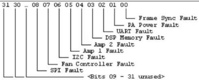
PAIMPED – PA Output Impedance
This command selects the output impedance for the PA channel to be either 8 ohms or 70/100V.
Command Form: DEVICE PIAMPED
Argument Type Size Values Units
Channel Channel 1 See Groups and Channels
Group Group 1 23 (J)
Value Unsigned 20 = 8 ohms Short 1 = 70/100V (Null to query in text)
PALEN – PA Limiter Enable
This command changes enables the Limiter on a power amplifier channel.
Command Form: DEVICE PALEN
Argument Type Size Values
Units
| Channel | Channel | 1 See Groups and Channels |
| Group | Group | 1 23 (J) |
| Value | Unsigned Short | 2 0 = Off |
| 1 = On | ||
| 2 = Toggle | ||
| (Null to query in text) |
PALT – PA Limiter Threshold
This command sets the Limiter threshold on a power amplifier channel.
Command Form: DEVICE PALT
Argument Type Size Values
Units
| Channel | Channel | 1 See Groups and Channels |
| Group | Group | 1 23 (J) |
| Value | Signed Float | 2 -65.00 to +20.00 (Null to query in text) dB |
PANGAT – PA Noise Gate Activation Timer
This command sets the Noise Gate activation timer. The noise gate will be activated if the timer conditions are met along with Gate thresholds.
Command Form: DEVICE PANGAT
Argument Type Size Values Units
Channel Channel 1 See Groups and Channels
Group Group 1 23 (J)
Value Unsigned Short 2 1 -16
Minutes
(Null to query in text)
PANGEN – PA Noise Gate Enabled
This command enables noise gating on a PA Channel.
Command Form: DEVICE PANGEN
Argument Type Size Values Units
Channel Channel 1 See Groups and Channels
Group Group 1 23 (J)
Value Unsigned Short 20 = No Filter
1 = High Pass
2 = Low Pass
3 = Hi and Low Pass
(Null to query in text)
PANGF – PA Noise Gate Filter
This command sets either a High Pass or Low Pass filter to be used in the activation of the noise gate. This will affect the threshold conditions for activation of the gate. A low pass will remove noise floor contributions to gate threshold above 500 HZ. A high pass will remove noise floor contribution to gate threshold above below 2K.
Command Form: DEVICE PANGF
Argument Type Size Values Units
Channel Channel 1 See Groups and Channels
Group Group 1 23 (J)
Value Unsigned Short 20 = Off
1 = On
2 = Toggle
(Null to query in text)
PANGM – PA Noise Gate Mode
This command sets the Noise Gate mode to be either manual or automatic. In manual mode the gate threshold will be used to activate. In auto mode the noise floor will be used to activate.
Command Form: DEVICE PANGM
Argument Type Size Values Units
Channel Channel 1 See Groups and Channels
Group Group 1 23 (J)
Value Unsigned Short 20 = Automatic
1 = Manual
(Null to query in text)
PANGT – PA Noise Gate Threshold
This command sets the Noise Gate Threshold that will be used when in the manual mode. This represents the level at which the noise gate will activate.
Command Form: DEVICE PANGT
Argument Type Size Values Units
Channel Channel 1 See Groups and Channels
Group Group 1 23 (J)
Value Signed Float 2 -100.00 to 0.00
dB
(Null to query in text)
PAPOL – Polarity Switch
This command changes audio signal polarity on a power amplifier channel.
Command Form: DEVICE PAPOL
Argument Type Size Values Units
Channel Channel 1 See Groups and Channels
Group Group 1 23 (J)
Value Unsigned Short 20 = Normal
1 = Reverse
2 = Toggle
(Null to query in text)
PARST – PA Reset
This command resets the power supplies on an individual power amplifier circuits. There is no query associated with this command.
Command Form: DEVICE PARST
Argument Type Size Values Units
Channel Channel 1 See Groups and Channels
Group Group 1 23 (J)
Reserved Zero
2 Zero
PASME – PA Sound Mask Enable
This command enables the sound mask signal on a PA Channel
Command Form: DEVICE PASME
Argument Type Size Values Units
Channel Channel 1 See Groups and Channels
Group Group 1 23 (J)
Value Unsigned Short 20 = Voice Mode
1 = Wideband Mode
(Null to query in text)
PASML – PA Sound Mask Level
This command selects/reports the sound mask level on a PA channel.
Command Form: DEVICE PASML
Argument Type Size Values Units
Channel Channel 1 See Groups and Channels
Group Group 1 23 (J)
Amplitude Signed Short 2 -60.00 - 20.00
dB
(Null to query in text)
PASMM – PA Sound Mask Mode
This command selects/reports the sound mask mode on a PA channel.
Command Form: DEVICE PASMM
Argument Type Size Values Units
Channel Channel 1 See Groups and Channels
Group Group 1 23 (J)
Value Unsigned Short 2 0 = Voice Mode
1 = Wideband Mode
(Null to query in text)
PASMT – PA Sound Mask Timer
This command selects/reports the timer on sound mask signal on a PA channel.
Command Form: DEVICE PASMT
Argument Type Size Values Units
Channel Channel 1 See Groups and Channels
Group Group 1 23 (J)
Value Unsigned Short 20 - 1440 (24 hours)
(Null to query in text)
Minutes
PATO – PA Thermal Overload
This indicates if a thermal overload condition is occurring on one of the power amplifier channels. This is Read-Only, and is automatically generated if a overload occurs.
Command Form: DEVICE PATO [Bitmap]
| Argument | Type | Size | Values | Units | ||||||||||||
| Bitmap | Hexadecimal Integer | 4 | 31 | 30 | ... | 08 | 07 | 06 | 05 | 04 | 03 | 02 | 01 | 00 | ||
| Fan IC Temp. Overload | ||||||||||||||||
| Intake Temp. Overload | ||||||||||||||||
| Outlet Temp. Overload | ||||||||||||||||
| <Bits 03 - 31 unused> | ||||||||||||||||
PBDIAL – Dial a PB Entry by Argument
This command dials a speed dial number by name. There is no query for this command.
Command Form: DEVICE PBDIAL
| Argument | Type Size Values | Units | ||
| Channel | Channel 1 See Groups and Channels | |||
| Group | Group 1 17 (R) | |||
| Reserved | Unsigned Integer | 2 0 | ||
| Label | String | 16 | 1 – 16 chars | |
PHONEBOOKADD – Adds an Entry to the Phonebook
This command saves an entry in the phonebook. There is no query for this command. No two entries can share the same label. An argument error will be returned if an entry already exists. To change an entry, you must first delete it and then add it again. If label is blank, the first 20 characters of the number will be used as the label. The Number argument must not be blank. If an entry already exists with the assigned speed dial it will be overwritten. The entries are alphabetized based on Label.
Command Form: DEVICE PHONEBOOKADD
| Argument | Type Size Values | Units |
Speed Dial Unsigned Integer 4 0 for not assigned to a speed dial
1 - 20
Number String 44 1 - 44 chars '0' - '9', '*', '#'
Label String 16 1 - 16 chars
PHONEBOOKCNT – Counts Entries in the Phonebook
This command queries the number of entries in the phonebook. This command is query only.
Command Form: DEVICE PHONEBOOKCNT
Argument Type Size Values Units
Value Unsigned Integer 40 - 20
PHONEBOOKDEL – Deletes an Entry in the Phonebook
This command deletes an entry in the phonebook. There is no query for this command.
Command Form: DEVICE PHONEBOOKDEL
Argument Type Size Values Units
Label String 16 1 - 16 chars
PHONEBOOKREAD – Queries the Phonebook by Index
This command queries an entry in the phonebook. This command is query only.
Command Form: DEVICE PHONEBOOKREAD
Argument Type Size Values
Units
| Index | Unsigned Integer 2 0 – 19 (Must be less than the Number of Phone Book Entries) |
| Speed Dial | Unsigned Integer 2 0 for not assigned to a speed dial1 – 20(NULL to query in text) |
| Number | String 44 1 – 44 chars ‘0’ – ‘9’, ‘*’, ‘#’ |
| Label | String 16 1 – 16 chars |
PP – Phantom Power
This command selects/reports the setting of phantom power.
Command Form: DEVICE PP
Argument Type Size Values
Units
| Channel | Channel | 1 See Groups and Channels |
| Group | Group | 1 3 (M) |
| Value | Unsigned Integer 2 0 = Off | |
| 1 = On | ||
| 2 = Toggle | ||
| (Null to query in text) | ||
PRESET – Preset Execution/Reporting
This command selects/reports the state of a preset.
Command Form: DEVICE PRESET
| Argument | Type | Size Values | Units | |
| Channel | Channel | 1 | 0 (Binary)/Null (Text) = Query Last Preset RanSeeGroups and Channels | |
Group Group 1 13 (S)
Value Unsigned Integer 20 = Set preset state to off
1 = Set state to on and execute if not already on
2 = Execute and return state to off
(Null to query current state in text)
PRGSTRING – Program String
This command sets/reports a programmed string.
COMMAND FORM: DEVICE PRGSTRING
Argument Type Size Values Units
ID Unsigned Integer 40-7
Value String 80 CLEAR = Clear current value
1 - 80 Chars
(Null to query in text)
Special Characters:
\a = alert
\b = backspace
\f = form feed
\n = new line
\r = carriage return
\t = horizontal tab
\v = vertical tab
\ = backslash
PROXYSTAT – Proxy Registration Status
This command reports the registration status for the primary or secondary proxy. This command is only queried, not set, and can be sent asynchronously.
Command Form: DEVICE PROXYSTAT
| Argument Type | Size Values | Units |
| Index Channel Index | 1 0 = Primary Proxy | |
| 1 = Secondary Proxy | ||
| Group Group | 1 129 (No text group) | |
| Value Signed Float | 2 0 = SIP Proxy Disabled | |
| 1 = SIP Proxy Registered | ||
| 2 = SIP Proxy NOT Registered |
PTTTHRESHOLD – Push to Talk Threshold
This command selects/reports the setting of the push to talk threshold for a microphone.
Command Form: DEVICE PTTTHRESHOLD
| Argument Type Size Values | Units | ||
| Channel | Channel | 1 See Groups and Channels | |
| Group Group | 1 3 (M) | ||
| Value Float | 2 -100 to 0 | dB | |
| (Null to query in text) | |||
PUSHTOTALK – Push to Talk
This command selects/reports the setting of push-to-talk for a microphone.
Command Form: DEVICE PUSHTOTALK
Argument Type Size Values Units
| Channel | Channel | 1 See Groups and Channels |
| Group Group | 1 3 (M) | |
Value Unsigned Integer 2 0 = Off
1 = On
2 = Toggle
(Null to query in text)
RAMP – Ramp Gain Adjustment
This command starts / stops the gain ramp for an input, output or assignable processing block. There is no query associated with this command.
Command Form: DEVICE RAMP
Argument Type Size Values Units
| Channel Channel 1 See Groups and Channels | ||||
| Group | Group | 1 | 1, 2, 3, 5, 7, 12, 16, 17, 25, 26 (I, J, O, M, P, L, F, T, R, K, Z) | |
| Rate | Signed Integer | 1 -50 – 50 | If value=0, the ramp will stop.If value< 0, the gain will ramp down.If value>0, the gain will ramp up. | dB / s |
| Target Signed Integer | 1 -65 – 20 | If NULL in text or 0x80 in binary, the ramp will use the channel's maximum and minimum for a target. | dB | |
REDIAL – Redial the Last Number
This command redials the last number. There is no query for this command.
Command Form: DEVICE REDIAL
| Argument | Type | Size Values | Units |
| Channel | Channel | 1 SeeGroups and Channels | |
| Group | Group | 1 17 (R) | |
| Reserved | 2 0 |
REFSEL – Reference Select for PA Adaptation & AEC
This command selects/reports which output or expansion bus reference is used for a Mic input as a reference for power amp adaptation mode and acoustic echo cancellation where applicable.
Command Form: DEVICE REFSEL
| Argument | Type | Size Values | Units | |
| Channel | Channel | 1 | See 3 (M) inGroups and Channels | |
| Group | Group | 1 3 (M) | ||
| Reference Group Group | 1 2, 8, 20 (A, B, E, H, J, O) | |||
| Reference Channel | Channel | 1 | SeeGroups and Channels(Null to query in text) | |
REFSET – Reference Channel Set Up
This command selects/reports the output the reference channel tracks.
Command Form: DEVICE REFSET
| Argument Type | Size Values | Units | |
| Channel | Channel | 1 SeeGroups and Channels | |
| Group | Group | 1 20 (B) | |
| Value | Reference Output | 2 0 = noneSee 2 (O) inGroups and Channels(Null to query in text) | |
RESET – Reset
Resets the unit. There is no query for this command.
Command Form: DEVICE RESET
No Arguments
RING – Ring Indication
This command indicates a ringing line. This command is reportable only. It cannot be queried or set.
Command Form: DEVICE RING
Argument Type Size Values Units
| Channel Channel 1 See Groups and Channels | |
| Group Group 1 17 (R) | |
| Value Unsigned | 20 = Ring Cycle Ended |
| Integer | 1 = Ring Cycle Started |
RINGEREN – Audible Ring Enable
This command sends/reports the use of an audible ring.
Command Form: DEVICE RINGEREN
| Argument Type Size Values | Units | ||
| Channel | Channel | 1 SeeGroups and Channels | |
| Group | Group | 1 17 (R) | |
| Value | Unsigned Integer | 2 0 = Off | |
| 1 = On | |||
| 2 = Toggle | |||
| (Null to query in text) | |||
RINGERLVL – Audible Ring Level
This command selects/reports the audible ring's level.
Command Form: DEVICE RINGERLVL
| Argument | Type | Size | Values | Units |
| Channel | Channel | 1 | SeeGroups and Channels | |
| Group | Group | 1 | 17 (R) | |
| Value | Signed Float | 2 | -12.00 – 12.00 (dB)(Null to query in text) |
RINGERSEL – Audible Ring Melody Selection
This command sends/reports the audible ring melody.
Command Form: DEVICE RINGERSEL
| Argument Type Size Values | Units | ||
| Channel | Channel | 1 SeeGroups and Channels | |
| Group | Group | 1 17 (R) | |
| Value | Unsigned Integer | 2 1 – 3(Null to query in text) | |
RINGERTEST – Audible Ring Melody Test
This command plays the current audible ringer melody. This command is executable only. There is no query.
Command Form: DEVICE RINGERTEST
Argument Type Size Values Units
Channel Channel 1 See Groups and Channels
Group Group 1 17 (R)
Reserved Unsigned Integer 2 0
RINGMOD – Ring Cadence Mode
This command sets the ring cadence to either standard mode or custom mode. The cadence can be set using the RINGON and RINGOFF commands. The country code should be set first using the COUNTRY command.
Command Form: DEVICE RINGMOD
Argument Type Size Values Units
Channel Channel 1 See Groups and Channels
Group Group 1 17 (R)
Value Unsigned Short 20 = Standard
1 = Custom
(Null to query in text)
RINGOFF – Ring Cadence Off Time
This command sets the ring cadence off time. The country code should be set first using the COUNTRY command.
Command Form: DEVICE RINGOFF
Argument Type Size Values Units
Channel Channel 1 See Groups and Channels
Group Group 1 17 (R)
Value Unsigned Short 20 = 80
ms
1 = 128
2 = 256
3 = 384
4 = 512
5 = 640
6 = 768
7 = 896
8 = 1024
(Null to query in text)
RINGON – Ring Cadence On Time
This command sets the ring cadence on time. The country code should be set first using the COUNTRY command.
Command Form: DEVICE RINGON
Argument Type Size Values Units
Channel Channel 1 See Groups and Channels
Group Group 1 17 (R)
Value Unsigned Short 20 = 100
ms
1 = 150
2 = 200
3 = 256
4 = 384
5 = 512
6 = 640
7 = 1024
(Null to query in text)
RXBOOST – Receive Boost
This command selects/reports the receive boost status.
Command Form: DEVICE RXBOOST
Argument Type Size Values Units
Channel Channel 1 See Groups and Channels
Group Group 1 17 (R)
Value Unsigned Integer 2 0, 3, 6, 9, or 12
dB
(Null to query in text)
RXBSTEN – Receive Boost Enable
This command selects/reports the receive boost status.
Command Form: DEVICE RXBSTEN
Argument Type Size Values Units
Channel Channel 1 See Groups and Channels
Group Group 1 17 (R)
Value Unsigned Integer 2 0 = Off
1 = On
2 = Toggle
(Null to query in text)
SERECHO – Serial Echo
This command selects/reports the serial echo of the RS-232 port.
Command Form: DEVICE SERECHO [Value]
Argument Type Size Values
Units
Value Unsigned Integer 4 0 = Off
1 = On
2 = Toggle
(Null to query in text)
NOTE: The unit will return the updated state of the last selection in the same form as the command.
SFTYMUTE – Safety Mute
This command selects/reports the state of the safety mute. Safety mute holds all outputs in a muted state. It used for syncing to a site document to avoid feedback or blown speakers until the unit is in a settled state.
Command Form: DEVICE SFTYMUTE [Value]
| Argument | Type | Size Values | Units |
| Value | Channel | 4 0 = off | |
| 1 = on | |||
| 2 = toggle | |||
| (Null to query in text) |
SIGGEN – Signal Generator
This command selects/reports of the signal generator activation.
Command Form: DEVICE SIGGEN [Channel Group Type Amplitude Frequency]
Argument Type Size Values Units
| Channel Channel 1 See Groups and Channels | |||||
| (Null to query in text) | |||||
| Group Group 1 1, 3, 7 (I, M, L) | |||||
| Type Unsigned Integer 2 1 = Pink Noise | |||||
| 2 = White Noise | |||||
| 3 = Tone | |||||
| Amplitude Signed Float | 4 -60.00 – 20.00 | dB | |||
| Frequency | Unsigned Float | 4 | Type 1 – 2 | 0 (Null in text) | Hz |
| Type 3 | 20.00 – 20000.00 | ||||
SIGGENEN – Signal Generator Enable
This command selects/reports of the signal generator activation.
Command Form: DEVICE SIGGENEN [Value]
Argument Type Size Values Units
| Value | Unsigned Integer 4 0 = Off |
| 1 = On | |
| 2 = Toggle | |
| (Null to query in text) |
SIGGENSWEEP – Signal Generator Sweep
This command starts the signal generator with a tone and does a sweep. If Repeat is 0, the signal generator will turn off after the sweep. If Repeat is 1, the signal generator will turn off after signal generator timeout. To stop the sweep, send a SIGGENEN command with a 0. During the sweep, the box will send out updated SIGGEN commands.
Command Form:
DEVICE SIGGENSWEEP
Argument Type Size Values Units
| Channel Channel 1 See Groups and Channels | |||
| Group Group 1 1, 3, 7 (I, M, L) | |||
| Amplitude Signed Float | 2 -60.00 – 20.00 | dB | |
| Start | Unsigned Float | 4 20.00 – 20000.00 | Hz |
| Frequency | |||
| End | Unsigned Float | 4 20.00 – 20000.00 (must be greater than the start) | Hz |
| Frequency | |||
| Increment | Unsigned Float | 4 1.00 – 20000.00 | Hz |
| Frequency | |||
| Rate Unsigned Integer 2 10 – 2000 ms | Hz | ||
| Repeat | Unsigned Integer 2 0 = repeat off | ||
| 1 = repeat on | |||
SIGTOUT – Signal Generator Time Out
Sets the signal generator time out for the unit.
Command Form: DEVICE SIGTOUT [Value]
Argument Type Size Values Units
| Value | Unsigned Integer 4 0 = Disable | Min |
| 1 - 30 | ||
| (Null to query in text) |
SLVL – Speech Level Control
This command selects/reports the setting of Speech Level Control.
Command Form: DEVICE SLVL
Argument Type Size Values Units
Channel Channel 1 See Groups and Channels
Group Group 1 3 (M)
Value Unsigned Integer 2 0 = Off
1 = On
2 = Toggle
(Null to query in text)
SMTPSRV – SMTP Mail Server Address
This command selects/reports the IP address of the SMTP Mail server, and the Email Address the unit's SMTP client sends messages to.
Command Form: DEVICE SMTPSRV [Value Address]
| Argument Type | Size | Values | Units | |
| Value | IP Address | 4 (Null to query in text) | ||
| (0.0.0.0 Clears IP and String) | ||||
| Address String | 40 | 1 – 40 characters | ||
| (Null to query in text) | ||||
SNMPMNGRIP – SNMP Manager Host IP Address
This command selects/reports the IP address of the SNMP Manager.
Command Form: DEVICE SNMPMNGRIP [Value]
| Argument | Type Size | Values | Units |
| Value | IP Address | 4 | IP Address of SNMP Manager to send Traps to (Null to query in text) |
SNMPMNGRPORT – SNMP Manager Notification Port
This command selects/reports the SNMP Trap port for SNMP Manager.
Command Form: DEVICE SNMPMNGRPORT [Value]
| Argument | Type Size Values | Units |
| Value | Unsigned Integer 4 1-255 | (Null to query in text) |
SNMPREADCOMM – SNMP Read Community String
This command selects/reports the SNMP read community string.
Command Form: DEVICE SNMPREADCOMM [Value]
| Argument | Type | Size | Values | Units |
| Value | String | 30 | Read Community validation string (GET data)(Null to query in text: defaults to “public”) |
SNMPWRITECOMM – SNMP Write Community String
This command selects/reports the SNMP Write Community String.
Argument Type Size Values Units
Value String 30 Write Community validation string (SET data)
(Null to query in text: Default = "private")
SPEEDDIAL – Speed Dial a Number
This command dials a speed dial number.
Command Form: DEVICE SPEEDDIAL
Argument Type Size Values Units
| Channel Channel 1 See Groups and Channels | ||
| Group | Group | 1 17 (R) |
| Value | Unsigned Integer | 2 1 – 20 |
| (Null to query in text) | ||
STRING – String Execution
This command sends the specified string out the serial port.
Command Form: DEVICE STRING [ID]
Argument Type Size Values
Units
| ID | Unsigned Integer | 40-7 |
(Null to query last string in text)
SYSCHECKS – System Checks
Initiates the system checks. There is no query for this command.
The System Check integer bits determine which tests are run. Each bit set generates a separate SYSRESULT response.
COMMAND FORM: DEVICE SYSCHECKS
Argument Type
Size Values
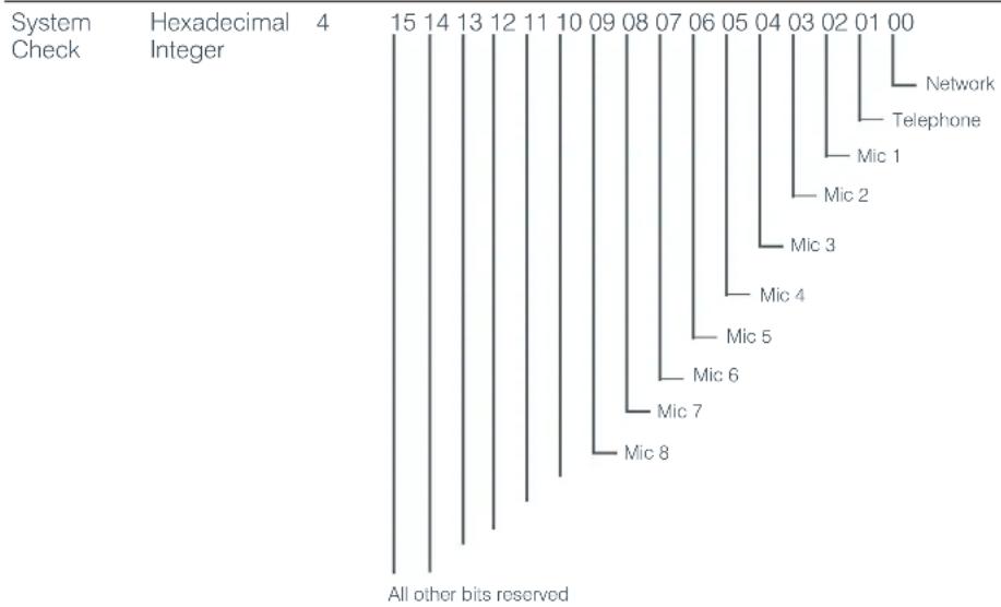
tree
| Bit Position | Bit Name | Bit Description | | :--- | :--- | :--- | | 4 | Hexadecimal | 15 14 13 12 11 10 09 08 07 06 05 04 03 02 01 00 | | All other bits reserved | | | Network Telephone Mic 1 Mic 2 Mic 3 Mic 4 Mic 5 Mic 6 Mic 7 Mic 8 | |SYSRESULT – System Check Result
This command reports the results of the system check. This command is reportable only. It cannot be queried or set. The System Check integer bits determine which test result will be reported. Each test results in a separate SYSRESULT message.
Argument Type Size Values
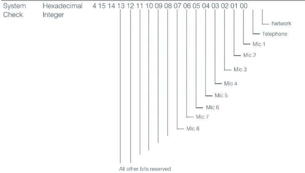
tree
| Bit | Hexadecimal | Integer | |---|---|---| | 4 | 15 | 14 | | 13 | 12 | 11 | | 10 | 09 | 08 | | 08 | 07 | 06 | | 05 | 04 | 03 | | 02 | 01 | 00 | | All other bits reserved| Status Unsigned | 20 = Fail |
| Integer | 1 = Pass |
| 2 = NULL <Not Tested or Test Disabled in SYSCONFIG> | |
| Message String 40 For the telephone on hook: the message will report the line voltage, the line current, other results, and if dial tone is detected. | |
| For the telephone off hook: the message will report the line current, other results, and if dial tone is detected. The bit mask for the other results is | |
| xxxx xxxx | |
| | | | | | | | | --> set if switched from CTR21 to FCC because of low current | |
| | | | | | | | --> set if used DIAL bit while dialing | |
| | | | | | | --> set if switch from Low Voltage to Japan because of current | |
| | | | | | --> set if switch from Low Voltage to FCC because of current | |
| | | | | --> DAA OVL status | |
| | | | --> DAA DOD status | |
| | | --> DAA OPD status | |
| | --> Not used | |
For the network check: the box will report if no IP address is set. If it is set, the box will ping the gateway. The message will say the ping failed if it is not returned in 5 s. Otherwise, the message will report how many seconds it took to return the ping.
TAMODE – Telco Adapt Mode
This command selects/reports the Telco adapt mode.
Command Form: DEVICE TAMODE
Argument Type Size Values Units
| Channel | Channel | 1 | See Groups and Channels |
| Group | Group | 1 | 17 (R) |
| Value | Unsigned Integer | 2 | 0 = Auto1 = Burst(Null to query in text) |
TE – Telco Enable
This command selects/reports the hook status.
Command Form: DEVICE TE
Argument Type Size Values Units
Channel Channel 1 See Groups and Channels
Group Group 1 17 (R)
Value Unsigned Integer 2 0 = Off
1 = On
2 = Toggle
(Null to query in text)
TELCOLVLCTRL – Telco RX Level Control Enable / Disable
This command selects/reports the setting of Telco Rx level control.
Power Amp Temp Check
Command Form: DEVICE TELCOLVLCTRL
SIP Proxy Registration Status
Argument Type Size Values Units
Packet Loss Statistics
Channel Channel 1 See Groups and Channels
Group Group 1 17 (T)
Value Unsigned Integer 2 0 = Off
1 = On
2 = Toggle
(Null to query in text)
TELOVER – Telco Current Overload
This command reports that the Telco circuitry has experienced a current overload that has forced it to go off hook. This condition can occur because of a connection to a Digital PBX, and is done to protect the Telco Circuitry from damage. The command is a notification only, and cannot be set or queried.
Command Form: DEVICE TELOVER
Argument Type Size Values Units
Channel Channel 1 See Groups and Channels
Group Group 1 17 (R)
Value Unsigned Short 20 = Not Overloaded
1 = OVERLOADED
TIMELOCALE – Time Locale Settings
This command sets or reports the time locale settings.
Command Form: DEVICE TIMELOCALE [DaylightSavings TimeZone TimeZoneName]
| Argument | Type | Size Values | Power Amp Temp CheckPower Amp Fault Check | Units |
| Daylight Savings | Unsigned Integer | 4 | 0 = Do not use Daylight SavingsSIP Proxy Registration Status1 = Use Daylight SavingsPacket Loss Statistics(NULL to Query in Text) | |
| Time Zone | Unsigned Integer | 4 | The number of seconds from UDT. (-86400 - 86400) | |
| Time Zone Argument | String | 32 | Description of time zone |
TOUT – Time Out Select
This command selects/reports the inactivity time out before returning to the unit title screen on the front panel.
Command Form: DEVICE TOUT [Value]
Argument Type Size Values Units
| Value Unsigned Integer 4 0 = No Time Out | Min |
| 1 – 15 | |
| (Null to query in text) |
UID - Unit ID
This command reports the unit id. This command is read only.
Command Form: DEVICE UID [Value]
Argument Type Size Values Units
Value Hexadecimal 4 (Sent with a Null, value returned in text)
VER - Version
This command reports the version of the unit. This command is read only.
Command Form: DEVICE VER [Value]
Argument Type Size Values Units
Value String 8 Version of format MM.mm.rr (Sent with a Null in text, value returned)
XAA – Auto Answer Enable/Disable
This command selects/reports the setting of auto answer. This command can be used to replace the AA command for the R group.
Command Form: DEVICE XAA
| Argument | Type Size Values | Units | |
| Channel | Channel | 1 See Groups and Channels | |
| Group | Group | 1 17, 26 (R, Z) | |
| Value | Unsigned Short | 2 0 = Off | |
| 1 = On | |||
| 2 = Toggle | |||
| (Null to query in text) |
XAARINGS – Number of Rings to Auto Answer On
This command selects/reports the setting of the number of rings to auto answer. This command can be used to replace the AARINGS command for the R group.
Command Form: DEVICE XAARINGS
| Argument | Type Size Values | Units | |
| Channel | Channel | 1 See Groups and Channels | |
| Group | Group | 1 17, 26 (R, Z) | |
| Value | Unsigned Short | 2 2-4 | |
| (Null to query in text) |
XACONN – Audible Connect / Disconnect Indication
This command selects/reports the status of the audible connect / disconnect indication. This command can be used to replace the ACONN command for the R group.
Command Form: DEVICE XACONN
Argument Type Size Values Units
Channel Channel 1 See Groups and Channels
Group Group 1 17, 26 (R, Z)
Value Unsigned Short 2 0 = Off
1 = On
2 = Toggle
(Null to query in text)
XACONNLVL – Audible Connect / Disconnect Level
This command selects/reports the audible connect / disconnect indicator's level. This command can be used to replace the ACONNLVL command for the R group.
Command Form: DEVICE XACONNLVL
Argument Type Size Values
Units
Channel Channel 1 See Groups and Channels
Group Group 1 17, 26 (R, Z)
Value Signed Short 2 -12.00 - 12.00
dB
(Null to query in text)
XCALLDUR – Call Duration
This command indicates how long a call has lasted. If no call is in session, this will report 0. At the time of call termination, this command will automatically be sent out reporting the duration. This command can be used to replace the CALLDUR command for the R group.
Command Form: DEVICE XCALLERID
Argument Type Size Values
Units
| Channel Channel 1 See Groups and Channels | |||
| Group Group 1 17, 26 (R, Z) | |||
| Number | String | 44 | 1-44 Characters |
| Name | String | 44 | 1-44 Characters |
XCALLERID – Reports Caller ID Information
This command reports Caller Identification Information. This command can be used to replace the CALLERID command for the R group. This command is reportable only. It cannot be queried or set.
Command Form: DEVICE XCALLDUR
Argument Type Size Values
Units
| Channel Channel 1 See Groups and Channels | ||
| Group Group 1 17, 26 (R, Z) | ||
| Reserved | Unsigned Short 2 0 | |
| Duration | String | 8 String of format HR:MN:SS |
XCGROUP – Compressor Group
This command sets the compressor group for synchronized operation of the compressor. This command can be used to replace the CGROUP command for the P group.
Command Form: DEVICE XCGROUP
Argument Type Size Values
Units
Channel Channel 1 See Groups and Channels
Group Group 1 5, 23 (P, J)
Value Unsigned Short 20 = None
1 = Group 1
2 = Group 2
3 = Group 3
4 = Group 4
(Null to query in text)
XCOMPRESS – Compressor Adjust
This command controls/reports the signal compression setting on a Channel. This command can be used to replace the COMPRESS command for the P group.
Command Form: DEVICE XCOMPRESS
Argument Type Size Values Units
Channel Channel 1 See Groups and Channels
Group Group 1 23 (J, P)
Value Unsigned Short 2 0 = Off
1 = On
2 = Toggle
(Null to query in text)
XCOMPSEL – Compressor Enable
This command enables signal compression on a Channel. This command can be used to replace the COMPSEL command for the P group.
Command Form: DEVICE XCOMPSEL
Argument Type Size Values Units
Channel Channel 1 See Groups and Channels
Group Group 1 23 (J, P)
Value Unsigned Short 2 0 = Off
1 = On
2 = Toggle
(Null to query in text)
XDELAY – Audio Delay
This command controls/reports signal delay on a Channel. This command can be used to replace the DELAY command for the P group.
Command Form: DEVICE XDELAY
Argument Type Size Values
Units
Channel Channel 1 See Groups and Channels
Group Group 1 5, 23 (P, J)
Value Unsigned Short 2 0.0 - 250.00
ms
(Null to query in text)
XDELAYSEL – Audio Delay Enable
This command enables signal delay on a Channel. This command can be used to replace the DELAYSEL command for the P group.
Command Form: DEVICE XDELAYSEL
Argument Type Size Values
Units
Channel Channel 1 See Groups and Channels
Group Group 1 5, 23 (P, J)
Value Unsigned Short 20 = Off
1 = On
2 = Toggle
(Null to query in text)
XDELAYSEL – Audio Delay Enable
This command enables signal delay on a Channel. This command can be used to replace the DELAYSEL command for the P group.
Command Form: DEVICE XDELAYSEL
Argument Type Size Values Units
Channel Channel 1 See Groups and Channels
Group Group 1 5, 23 (P, J)
Value Unsigned Short 2 0 = Off
1 = On
2 = Toggle
(Null to query in text)
XDIAL – DTMF Dialing
This command dials a DTMF sequence or reports back the last sequence dialed. This command can be used to replace the DIAL command for the R group.
Command Form: DEVICE XDIAL
Argument Type Size Values Units
Channel Channel 1 See Groups and Channels
Group Group 1 17, 26 (R, Z)
Reserved Unsigned Short 20
Number String 44 1 - 44 Chars of '0' - '9', '*', '#',
(Null to query in text)
XDTMFLVL - DTMF Tone Level
This command selects/reports the DTMF tone's level. This command can be used to replace the DTMFLVL command for the R group. You can't change level during a call.
Command Form: DEVICE XDTMFLVL
Argument Type Size Values Units
Channel Channel 1 See Groups and Channels
Group Group 1 17, 26 (R, Z)
Value Signed Short 2 -12.00 - 12.00
dB
(Null to query in text)
XDTONELVL – Dial Tone Level
This command selects/reports the audible dial tone's level. This command can be used to replace the DTONELVL command for the R group. You can't change level during a call.
Command Form: DEVICE XDTONELVL
Argument Type Size Values Units
| Channel Channel 1 See Groups and Channels | |
| Group Group 1 17, 26 (R, Z) | |
| Value Signed Short 2 -12.00 – 12.00 | dB |
| (Null to query in text) | |
XHOOK – Hook Flash
This command sends a hook flash. This command can be used to replace the HOOK command for the R group. There is no query for this command.
Command Form: DEVICE XHOOK
Argument Type Size Values Units
| Channel Channel 1 See Groups and Channels Group Group 1 17, 26 (R, Z) | |
| Reserved Unsigned Short | 2 0 |
XHOOKD – Hook Flash Duration
This command selects/reports the hook flash duration. This command can be used to replace the HOOKD command for the R group.
Command Form: DEVICE XHOOKD
Argument Type Size Values Units
| Channel Channel 1 See Groups and Channels | ||
| Group Group 1 17, 26 (R, Z) | ||
| Reserved Unsigned Short | 2 50 – 2000 | Ms |
| (Multiples of 10 Ms only) | ||
| (Null to query in text) | ||
This command sets or reports back the current value of the local number. This command can be used to replace the LOCALNUM command for the R group.
Command Form: DEVICE XLOCALNUM
Argument Type Size Values Units
| Channel Channel 1 See Groups and Channels Group Group 1 17, 26 (R, Z) | |
| Reserved Unsigned Short | 2 0 |
Number String 16 1 - 16 Chars of '0' - '9', '*', '#', '
XPBDIAL – Dial a PB Entry by Name
This command dials a speed dial number by name. This command can be used to replace the PBDIAL command for the R group. There is no query for this command.
Command Form: DEVICE XPBDIAL
Argument Type Size Values Units
Channel Channel 1 See Groups and Channels
Group Group 1 17, 26 (R, Z)
Reserved Unsigned Short 20
Number String 16 1 - 16 Chars
XREDIAL – Dial the last number again
This command redials the last number. This command can be used to replace the REDIAL command for the R group. There is no query for this command.
Command Form: DEVICE XREDIAL
Argument Type Size Values Units
Channel Channel 1 See Groups and Channels
Group Group 1 17, 26 (R, Z)
Reserved Unsigned Short 20
XRING – Ring Indication
This command indicates a ringing line. This command can be used to replace the RING command for the R group. This command is reportable only. It cannot be queried or set.
Command Form: DEVICE XRING
Argument Type Size Values Units
Channel Channel 1 See Groups and Channels
Group Group 1 17, 26 (R, Z)
Value Unsigned Short 20 = Ring Cycle Ended 1 = Ring Cycle Started
XRINGEREN – Audible Ring Enable
This command sends/reports the use of an audible ring. This command can be used to replace the RINGEREN command for the R group.
Command Form: DEVICE XRINGEREN
Argument Type Size Values Units
Channel Channel 1 See Groups and Channels
Group Group 1 17, 26 (R, Z)
Value Unsigned Short 20 = Off 1 = On 2 = Toggle (Null to query in text)
XRINGERLVL – Audible Ring Level
This command selects/reports the audible ring's level. This command can be used to replace the RINGERLVL command for the R group. You cannot change this value while the phone is ringing.
Command Form: DEVICE XRINGERLVL
Argument Type Size Values Units
Channel Channel 1 See Groups and Channels
Group Group 1 17, 26 (R, Z)
Value Unsigned Short 2 -12.00 - 12.00 (dB)
dB
(Null to query in text)
XRINGERSEL – Audible Ring Melody Selection
This command sends/reports the audible ring melody. This command can be used to replace the RINGERSEL command for the R group. You can't change the value while phone is ringing.
Command Form: DEVICE XRINGERSEL
Argument Type Size Values Units
Channel Channel 1 See Groups and Channels
Group Group 1 17, 26 (R, Z)
Value Unsigned Short 21-5
(Null to query in text)
XRINGERTEST – Audible Ring Melody Test
This command plays the current audible ringer melody. This command can be used to replace the RINGERTEST command for the R group. This command is executable only. There is no query.
Command Form: DEVICE XRINGERTEST
Argument Type Size Values Units
Channel Channel 1 See Groups and Channels
Group Group 1 17, 26 (R, Z)
Reserved Unsigned Short 20
XSPEEDDIAL – Speed Dialing
This command dials a speed dial number. This command can be used to replace the SPEEDDIAL command for the R group.
Command Form: DEVICE XSPEEDDIAL
Argument Type Size Values Units
Channel Channel 1 See Groups and Channels
Group Group 1 17, 26 (R, Z)
Value Unsigned Short 2 1 - 20
(Null to query in text)
XTE – Telco Enable
This command selects/reports the hook status. This command can be used to replace the TE command for the R group.
Command Form: DEVICE XTE
Argument Type Size Values Units
Channel Channel 1 See Groups and Channels
Group Group 1 17, 26 (R, Z)
Value Unsigned Short 20 = Off
1 = On
2 = Toggle
(Null to query in text)
SERIAL COMMAND SUPPORT TABLE
The following table shows serial command support by Converge/Converge Pro device type. Note that telco-related commands only work on models that have telephone interfaces (Converge Pro 880TA, 880T, 840T, TH20); and AEC and NC-related commands do not work with Converge SR 1212 and SR 1212A.
| Command Name | Converge Pro 880 | Converge Pro 880T | Converge Pro 840T | Converge Pro 8i | Converge Pro TH20 | Converge SR 1212 | Converge 880TA | Converge SR 1212A | Converge Pro VH20 |
| AA XXXX | |||||||||
| AAMB XXXXXX | |||||||||
| AARINGS XXXX | |||||||||
| ACONN XXXX | |||||||||
| ACONNLV XXXX | |||||||||
| AD XXXX | |||||||||
| ADCLIP XXXXXXXXX | X | ||||||||
| ADPRESENT | XXXXXXXXX | XX | |||||||
| AEC | XXXX | X | |||||||
| AGC | XXXXXXXXX | XX | |||||||
| AGCSET | XXXXXXXXX | XX | |||||||
| AMBLVL | XXXXXXXXX | ||||||||
| AMXDUET | XXXXXXXXX | XX | |||||||
| AV | XXXXXXXXX | X | |||||||
| AVG | XX | ||||||||
| AVR | XX | ||||||||
| AVRT | XX | ||||||||
| AVT | XX | ||||||||
| AUDIOMASTER | XXXXXXXXX | XX | |||||||
| BAUD XXXXXXXXX | X | ||||||||
| CALLDUR | XXXX | ||||||||
| CALLERID | XXXX | ||||||||
| CGROUP | XXXXXXXXX | ||||||||
| CHAIRO | XXXXXXXXX | ||||||||
| CLEAREFFECT | XXXX | ||||||||
| CLOCK | XXXXXXXXX | XX | |||||||
| COMPDLY | XX | ||||||||
| COMPDLYEN | XX | ||||||||
| COMPRESS | XXXXXXXXX | ||||||||
| COMPSEL | XXXXXXXXX | ||||||||
| COUNTRY | XXXXX | ||||||||
| CTRLMASTER XXX | XXXXXXXXX | ||||||||
| DECAY | XXXXXXXXX | ||||||||
| DEFAULT | X | X | X | X | X | X | X | X | X |
| DELAY | XXXXXXXXX | ||||||||
| DELAYSEL | XXXXXXXXX | ||||||||
| DEVICENAME | X | X | X | X | X | X | X | X | X |
| DEVICESUBTYPE | XXXXX | XXXX | |||||||
| DEVICETYPE | XXXXX | XXXX | |||||||
| DFLTM | XXXXX | X | X | ||||||
| DIAG | XX | ||||||||
| DIAL | XXXXX | ||||||||
| Command Name | Converge Pro 880 | Converge Pro 880T | Converge Pro 840T | Converge Pro 81 | Converge Pro TH20 | Converge SR 1212 | Converge 880TA | Converge SR 1212A | Converge Pro VH20 |
| DIDXXXXXXXXX | |||||||||
| DTMFLVLXXXX | |||||||||
| DTONFLVLXXXX | |||||||||
| UPDATEXXXXXXXXX | |||||||||
| OVERXXXXXXXXXX | |||||||||
| ENETADDRXXXXXXXXX | |||||||||
| ENETDHCPXXXXXXXXX | |||||||||
| ENETDNSXXXXXXXXX | |||||||||
| ENETDNSAXXXXXXXXX | |||||||||
| ENETDNSA2XXXXXXXXX | |||||||||
| ENETDOMAINXXXXXXXXX | |||||||||
| ENETGATE | XXXXXXXXXX | ||||||||
| ENETQOSVAL | X | ||||||||
| ENETQOSDSCP | X | ||||||||
| ENETSUBNXXXXXXXXX | |||||||||
| ENETVLAN | X | ||||||||
| ENETVLANID | X | ||||||||
| ENETVLANPRI | X | ||||||||
| EREF | XXXXXXXXX | ||||||||
| EVENT | XXXXXXXXXX | ||||||||
| FE | XX | ||||||||
| FEB | XX | ||||||||
| FEDR | XX | ||||||||
| FEF | XX | ||||||||
| FEG | XX | ||||||||
| FEGL | XX | ||||||||
| FELD | XX | ||||||||
| FEM | XX | ||||||||
| FEN | XX | ||||||||
| FER | XX | ||||||||
| FERRG | XX | ||||||||
| FES | XX | ||||||||
| FESC | XX | ||||||||
| FILTER | XXXXXXXXX | ||||||||
| FILTSEL | XXXXXXXXX | ||||||||
| FLOW | XXXXXXXXX | ||||||||
| FMP | XXXXXXXXX | ||||||||
| GAIN | XXXXXXXXX | ||||||||
| GATEXXXXXXXXX | |||||||||
| GHOLD | XXXXXXXXX | ||||||||
| GMODE | XXXXXXXXX | ||||||||
| GOVER | XXXXXXXXX | ||||||||
| GPIOSTATUSXXXXXXXXX | |||||||||
| GRATIO | XXXX | XXX | |||||||
| GREPORT | XXXXXXXXX | ||||||||
| GRPSEL | XXXXXXXXX | ||||||||
| HOOK | XXXX | ||||||||
| Command Name | Converge Pro 890 | Converge Pro 880T | Converge Pro 840T | Converge Pro 81 | Converge Pro TH20 | Converge SR 1212 | Converge 880TA | Converge SR 1212A | Converge Pro VH20 |
| HOOKD XXXX | |||||||||
| LABEL XXXXXXXXX | |||||||||
| LCDCONTRAST XXXXXXXXX | |||||||||
| LMO XXXXXXX | |||||||||
| LOCALNUM XXXX | |||||||||
| LOCBLDG XXXXXXXXX | |||||||||
| LOCCITY XXXXXXXXX | |||||||||
| LOCCNTRY XXXXXXXXX | |||||||||
| LOCCOMP | XXXXXXXXXX | ||||||||
| LOCREGION | XXXXXXXXXX | ||||||||
| LOCROOM | XXXXXXXXXX | ||||||||
| LOCSITENAME | XXXXXXXXXX | ||||||||
| LOCSTATE | XXXXXXXX | XXX | |||||||
| LOGMASK | XXXXXXXXXX | ||||||||
| LVL | XXXXXXXXXX | ||||||||
| LVLREPORT | XXXXXXXXXX | ||||||||
| LVLREPORTEN | XXXXXXXX | XXX | |||||||
| MACRO | XXXXXXXXXX | ||||||||
| MANUFACTURER | X | X | X | X | X | X | X | X | X |
| MAX | XXXXXXXXXX | ||||||||
| MC | XX | ||||||||
| MCGAIN | XX | ||||||||
| MCMINMAX | XX | ||||||||
| MCMUTE | XX | ||||||||
| MCRAMP | XX | ||||||||
| MIN | XXXXXXXXXX | ||||||||
| MINMAX | XXXXXXXXXX | ||||||||
| MLINE XXXXXXX | |||||||||
| MMAX | XXXXXXXX | ||||||||
| MODEL | XXXXXXXXXX | ||||||||
| MTRX | XXXXXXXXXX | ||||||||
| MTRXCLEAR | XXXXXXXXXX | ||||||||
| MTRXLVL | XXXXXXXXXX | ||||||||
| MUTE | XXXXXXXXXX | ||||||||
| NAME | XXXXXXXXXX | ||||||||
| NCD XXXXXXX | X | ||||||||
| NCSEL | XXXXXXXX | X | |||||||
| NLP | XXXX | XX | |||||||
| NOM | XXXXXXXX | ||||||||
| NTPSRV | XXXXXXXXXX | ||||||||
| NULL | XXXXX | ||||||||
| OFFA | XXXXXXXX | ||||||||
| PAA | XXXXXXXX | ||||||||
| PACEN | XX | ||||||||
| PAENERGY | XX | ||||||||
| PAEQEN | XX | ||||||||
| PAEQRST | XX | ||||||||
| Command Name | Converge Pro 880 | Converge Pro 880T | Converge Pro 840T | Converge Pro 81 | Converge Pro TH20 | Converge SR 1212 | Converge 880TA | Converge SR 1212A | Converge Pro VH20 |
| PAEQSET X X | |||||||||
| PAFLT X X | |||||||||
| PAIMPED X X | |||||||||
| PALEN X X | |||||||||
| PALT X X | |||||||||
| PANGAT X X | |||||||||
| PANGEN X X | |||||||||
| PANGF X X | |||||||||
| PANGM X X | |||||||||
| PANGT X X | |||||||||
| PAPOL X X | |||||||||
| PARST X X | |||||||||
| PASME X X | |||||||||
| PASML X X | |||||||||
| PASSM | XX | ||||||||
| PASMT X X | |||||||||
| PATO | XX | ||||||||
| PBDIAL | X | X | X | X | X | ||||
| PHONEBOOKADD | X | X | X | X | X | ||||
| PHONEBOOKCNT | X | X | X | X | X | ||||
| PHONEBOOKDEL | X | X | X | X | X | ||||
| PHONEBOOKREAD | X | X | X | X | X | ||||
| PP | X | X | X | X | X | X | X | ||
| PRESET | X | X | X | X | X | X | X | X | X |
| PRGSTRING | X | X | X | X | X | X | X | X | X |
| PROXYSTAT | X | ||||||||
| PTTTHRESHOLD | X | X | X | X | X | X | |||
| PUSHTOTALK | X | X | X | X | X | X | |||
| RAMP | X | X | X | X | X | X | X | X | X |
| REDIAL | X | X | X | X | X | ||||
| REFSEL | X | X | X | X | X | X | X | ||
| REFSET | X | X | X | X | X | X | X | X | |
| RESET | X | X | X | X | X | X | X | X | |
| RING | X | X | X | X | |||||
| RINGEREN | X | X | X | X | |||||
| RINGERLYL | X | X | X | X | |||||
| RINGERSEL | X | X | X | X | |||||
| RINGERTEST | X | X | X | X | |||||
| RINCMOD | X | X | X | X | |||||
| RINGOFF | X | X | X | X | |||||
| RINGON | X | X | X | X | |||||
| RXBOOST | X | X | X | X | |||||
| RXBSTEN | X | X | X | X | |||||
| SERTCHO | X | X | X | X | X | X | X | X | X |
| SFTYMUTE | X | X | X | X | X | X | X | X | X |
| SIGGEN | X | X | X | X | X | X | X | X | X |
| SIGGENEN | X | X | X | X | X | X | X | X | X |
| SIGGENSweep XXXXXXXXX | |||||||||
| SIGTOUT XXXXXXXXX | |||||||||
| SLVL XXXXXXXX | |||||||||
| SMTPSV XXXXXXXXX | |||||||||
| SNMPMNGRIP XXXXXXXXX | |||||||||
| SNMPMNGRFORT XXXXXXXXX | |||||||||
| SNMPREADCOMM XXXXXXXXX | |||||||||
| SNMPWRITECOMM XXXXXXXXX | |||||||||
| SPEEDDIAL XXXX | |||||||||
| STRING | XXXXXXXXXX | ||||||||
| SYSCHECKS | XXXXXXXXXX | ||||||||
| SYSRESULT | XXXXXXXXXX | ||||||||
| TAMODE | XXXX | ||||||||
| TE | XXXX | ||||||||
| TELCOLVLCTRL | XXXX | ||||||||
| TELOVER | XXXX | ||||||||
| TIMELOCALE XXXXXXXXX | |||||||||
| TOUT | XXXXXXXXXX | ||||||||
| UID | XXXXXXXXXX | ||||||||
| VER | XXXXXXXXXX | ||||||||
| XAA | XXXX | X | |||||||
| XAARINGS | XXXX | X | |||||||
| XACONN | XXXX | X | |||||||
| XACONNLVL | XXXX | X | |||||||
| XACALLDUR | XXXX | X | |||||||
| XACALLERID | XXXX | X | |||||||
| XCGROUP | XXXXXXXXXX | ||||||||
| XCOMPRESS XXXXXXXXX | |||||||||
| XCOMPSEL | XXXXXXXXXX | ||||||||
| XDELAY | XXXXXXXXXX | ||||||||
| XDELAYSEL | XXXXXXXXXX | ||||||||
| XDIAL | XXXX | X | |||||||
| XDTMFLVL | XXXX | X | |||||||
| XDTONETLVL | XXXX | X | |||||||
| XHOOK | XXXX | X | |||||||
| XHOOKD | XXXX | X | |||||||
| XLQCALNUM | XXXX | X | |||||||
| XPDIAL | XXXX | X | |||||||
| XREDIAL | XXXX | X | |||||||
| XRING | XXXX | X | |||||||
| XRINGEREN | XXXX | X | |||||||
| XRINGERLVL | XXXX | X | |||||||
| XRINGERSEL | XXXX | X | |||||||
| XRINGERTEST | XXXX | X | |||||||
| XSPEEDDIAL | XX | XX | X | ||||||
| XTE | X | X | X | X | X | ||||
ALL MODELS: RS-232 PORT CONNECTING WITH TELNET
Users can connect to any unit via RS-232 and telnet. Available telnet commands are the same as those used in the Serial Command section of this appendix.
How to Connect with Telnet:
Use the telnet client of your choice• Telnet uses port 23•
- The user name and password are the same as used by Console. The default username is clearone and the default password is converge. These are not case sensitive.
- The telnet session will time out after 15 minutes of no receive data. A heart beat to keep the session alive will need to be used. ClearOne recommends using the VER command to establish a heart beat in order to keep the session alive.
ALL MODELS: RS-232 PORT
| Pin # User Definable Control | |
| 1 N DCD | |
| 2 N TXD | |
| 3 N RXD | |
| 4 N DTR | |
| 5 N Ground | |
| 6 N DSR | |
| 7 N CTS | |
| 8 N RTS | |
| 9 N No connection |
NOTE: To avoid communication errors, ClearOne recommends using all nine pins when connecting to the RS-232 port.
APPENDIX B: DEFAULT PINOUTS
CONTROL/STATUS PORTS
Converge Pro 880: Port A (Female DB-25)
| Pin # User Definable Control/Status Default Description | ||
| 1 Y Control (Input) | ||
| 2 Y Status (Output) | ||
| 3 Y Control (Input) Mute All Mics Toggle | ||
| 4 Y Status (Output) Status of Mute All Mics | ||
| 5 Y Control (Input) Mute Output 9 Toggle | ||
| 6 Y Status (Output) Status of Mute Output 9 | ||
| 7 Y Control (Input) Mute Output 10 Toggle | ||
| 8 Y Status (Output) Status of Mute Output 10 | ||
| 9 Y Control (Input) Mute Output 11 Toggle | ||
| 10 Y Status (Output) Status of Mute Output 11 | ||
| 11 Y Control (Input) Mute Output 12 Toggle | ||
| 12 Y Status (Output) Status of Mute Output 12 | ||
| 13 Y Control (Input) Volume Up Output 1 (1 dB) | ||
| 14 Y Status (Output) | ||
| 15 Y Control (Input) Volume Down Output 1 (1 dB) | ||
| 16 Y Status (Output) | ||
| 17 N Status (Output) Microphone 1 Gate Status | ||
| 18 N Status (Output) Microphone 2 Gate Status | ||
| 19 N Status (Output) Microphone 3 Gate Status | ||
| 20 N Status (Output) Microphone 4 Gate Status | ||
| 21 N Status (Output) Microphone 5 Gate Status | ||
| 22 N Status (Output) Microphone 6 Gate Status | ||
| 23 N Status (Output) Microphone 7 Gate Status | ||
| 24 N Status (Output) Microphone 8 Gate Status | ||
| 25 NA NA Ground | ||
Converge Pro 880T: Port A (Female DB-25)
| Pin # User Definable Control/Status Default Description | |
| 1 Y Control (Input) | |
| 2 Y Status (Output) | |
| 3 Y Control (Input) Mute All Mics Toggle | |
| 4 Y Status (Output) Status of Mute All Mics | |
| 5 Y Control (Input) Mute Output 9 Toggle | |
| 6 Y Status (Output) Status of Mute Output 9 | |
| 7 Y Control (Input) Mute Output 10 Toggle | |
| 8 Y Status (Output) Status of Mute Output 10 | |
| 9 Y Control (Input) Mute Output 11 Toggle | |
| 10 Y Status (Output) Status of Mute Output 11 | |
| 11 Y Control (Input) Mute Output 12 Toggle | |
| 12 Y Status (Output) Status of Mute Output 12 | |
| 13 Y Control (Input) Toggle Telco On/Off | |
| 14 Y Status (Output) Telco Toggle Status (On/Off) | |
| 15 Y Control (Input) | |
| 16 Y Status (Output) | |
| 17 N Status (Output) Microphone 1 Gate Status | |
| 18 N Status (Output) Microphone 2 Gate Status | |
| 19 N Status (Output) Microphone 3 Gate Status | |
| 20 N Status (Output) Microphone 4 Gate Status | |
| 21 N Status (Output) Microphone 5 Gate Status | |
| 22 N Status (Output) Microphone 6 Gate Status | |
| 23 N Status (Output) Microphone 7 Gate Status | |
| 24 N Status (Output) Microphone 8 Gate Status | |
| 25 NA NA Ground | |
Converge Pro 840T: Port A (Female DB-25)
| Pin # User Definable Control/Status Default Description | |
| 1 Y Control (Input) | |
| 2 Y Status (Output) | |
| 3 Y Control (Input) Mute All Mics Toggle | |
| 4 Y Status (Output) Status of Mute All Mics | |
| 5 Y Control (Input) Telco On/Off Toggle | |
| 6 Y Status (Output) Status of Telco On/Off | |
| 7 Y Control (Input) Auto Answer Toggle | |
| 8 Y Status (Output) Status of Auto Answer | |
| 9 Y Control (Input) Mute Output 5 Toggle | |
| 10 Y Status (Output) Status of Mute Output 5 | |
| 11 Y Control (Input) Mute Input 5 Toggle | |
| 12 Y Status (Output) Status of Mute Input 5 | |
| 13 Y Control (Input) Volume Up Output 8 (1 dB) | |
| 14 Y Status (Output) | |
| 15 Y Control (Input) Volume Down Output 8 (1 dB) | |
| 16 Y Status (Output) | |
| 17 N Status (Output) Microphone 1 Gate Status | |
| 18 N Status (Output) Microphone 2 Gate Status | |
| 19 N Status (Output) Microphone 3 Gate Status | |
| 20 N Status (Output) Microphone 4 Gate Status | |
| 21 Y Status (Output) | |
| 22 Y Status (Output) | |
| 23 Y Status (Output) | |
| 24 Y Status (Output) Ring Indication | |
| 25 NA NA Ground | |
Converge Pro 8i: Port A (Female DB-25)
| Pin # User Definable Control/Status Default Description | ||
| 1 Y Control (Input) | ||
| 2 Y Status (Output) | ||
| 3 Y Control (Input) Mute All Mics Toggle | ||
| 4 Y Status (Output) Status of Mute All Mics | ||
| 5 Y Control (Input) Mute Mic 1 Toggle | ||
| 6 Y Status (Output) Status of Mute Mic 1 | ||
| 7 Y Control (Input) Mute Mic 2 Toggle | ||
| 8 Y Status (Output) Status of Mute Mic 2 | ||
| 9 Y Control (Input) Mute Mic 3 Toggle | ||
| 10 Y Status (Output) Status of Mute Mic 3 | ||
| 11 Y Control (Input) Mute Mic 4 Toggle | ||
| 12 Y Status (Output) Status of Mute Mic 4 | ||
| 13 Y Control (Input) Mute Mic 5 Toggle | ||
| 14 Y Status (Output) Status of Mute Mic 5 | ||
| 15 Y Control (Input) Mute Mic 6 Toggle | ||
| 16 Y Status (Output) Status of Mute Mic 6 | ||
| 17 N Status (Output) Microphone 1 Gate Status | ||
| 18 N Status (Output) Microphone 2 Gate Status | ||
| 19 N Status (Output) Microphone 3 Gate Status | ||
| 20 N Status (Output) Microphone 4 Gate Status | ||
| 21 N Status (Output) Microphone 5 Gate Status | ||
| 22 N Status (Output) Microphone 6 Gate Status | ||
| 23 N Status (Output) Microphone 7 Gate Status | ||
| 24 N Status (Output) Microphone 8 Gate Status | ||
| 25 NA NA Ground | ||
Converge Pro TH20: Port A (Female DB-25)
| Pin # User | Definable Control/Status Default Description | |
| 1 Y Control (Input) Telco On | ||
| 2 Y Status (Output) Telco On Indicator | ||
| 3 Y Control (Input) Telco Off | ||
| 4 Y Status (Output) Telco off indicator | ||
| 5 Y Control (Input) | ||
| 6 Y Status (Output) | ||
| 7 Y Control (Input) | ||
| 8 Y Status (Output) | ||
| 9 Y Control (Input) Transmit Mute | ||
| 10 Y Status (Output) Transmit Mute status | ||
| 11 Y Control (Input) Receive Mute | ||
| 12 Y Status (Output) Receive mute status | ||
| 13 Y Control (Input) | ||
| 14 Y Status (Output) | ||
| 15 Y Control (Input) | ||
| 16 Y Status (Output) | ||
| 17 Y Status (Output) | ||
| 18 Y Status (Output) | ||
| 19 Y Status (Output) | ||
| 20 Y Status (Output) | ||
| 21 Y Status (Output) | ||
| 22 Y Status (Output) | ||
| 23 Y Status (Output) | ||
| 24 Y Status (Output) Ring Indication | ||
| 25 NA NA Ground | ||
Converge Pro VH20: Port A (Female DB-25)
| Pin # User | Definable Control/Status Default Description | |
| 1 Y Control (Input) Telco On | ||
| 2 Y Status (Output) Telco On Indicator | ||
| 3 Y Control (Input) Telco Off | ||
| 4 Y Status (Output) Telco off indicator | ||
| 5 Y Control (Input) | ||
| 6 Y Status (Output) | ||
| 7 Y Control (Input) | ||
| 8 Y Status (Output) | ||
| 9 Y Control (Input) Transmit Mute | ||
| 10 Y Status (Output) Transmit Mute status | ||
| 11 Y Control (Input) Receive Mute | ||
| 12 Y Status (Output) Receive mute status | ||
| 13 Y Control (Input) | ||
| 14 Y Status (Output) | ||
| 15 Y Control (Input) | ||
| 16 Y Status (Output) | ||
| 17 Y Status (Output) | ||
| 18 Y Status (Output) | ||
| 19 Y Status (Output) | ||
| 20 Y Status (Output) | ||
| 21 Y Status (Output) | ||
| 22 Y Status (Output) | ||
| 23 Y Status (Output) | ||
| 24 Y Status (Output) Ring Indication | ||
| 25 NA NA Ground | ||
Converge SR 1212: Port A (Female DB-25)
| Pin # User Definable Control/Status Default Description | |
| 1 Y Control (Input) | |
| 2 Y Status (Output) | |
| 3 Y Control (Input) Mute All Mics Toggle | |
| 4 Y Status (Output) Status of Mute All Mics | |
| 5 Y Control (Input) Mute Output 9 Toggle | |
| 6 Y Status (Output) Status of Mute Output 9 | |
| 7 Y Control (Input) Mute Output 10 Toggle | |
| 8 Y Status (Output) Status of Mute Output 10 | |
| 9 Y Control (Input) Mute Output 11 Toggle | |
| 10 Y Status (Output) Status of Mute Output 11 | |
| 11 Y Control (Input) Mute Output 12 Toggle | |
| 12 Y Status (Output) Status of Mute Output 12 | |
| 13 Y Control (Input) Volume Up Output 1 (1 dB) | |
| 14 Y Status (Output) | |
| 15 Y Control (Input) Volume Down Output 1 (1 dB) | |
| 16 Y Status (Output) | |
| 17 N Status (Output) Microphone 1 Gate Status | |
| 18 N Status (Output) Microphone 2 Gate Status | |
| 19 N Status (Output) Microphone 3 Gate Status | |
| 20 N Status (Output) Microphone 4 Gate Status | |
| 21 N Status (Output) Microphone 5 Gate Status | |
| 22 N Status (Output) Microphone 6 Gate Status | |
| 23 N Status (Output) Microphone 7 Gate Status | |
| 24 N Status (Output) Microphone 8 Gate Status | |
| 25 NA NA Ground | |
All Models: Port B (Female DB-25)
| Pin # User Definable Control/Status Default Description | |
| 1 N Control (Input) Preset Mask Bit 0 | |
| 2 N Status (Output) Preset Indicator Bit 0 | |
| 3 N Control (Input) Preset Mask Bit 1 | |
| 4 N Status (Output) Preset Indicator Bit 1 | |
| 5 N Control (Input) Preset Mask Bit 2 | |
| 6 N Status (Output) Preset Indicator Bit 2 | |
| 7 N Control (Input) Preset Mask Bit 3 | |
| 8 N Status (Output) Preset Indicator Bit 3 | |
| 9 N Control (Input) Preset Mask Bit 4 | |
| 10 N Status (Output) Preset Indicator Bit 4 | |
| 11 N Control (Input) Preset Mask Bit 5 | |
| 12 N Status (Output) Preset Indicator Bit 5 | |
| 13 N Control (Input) Preset Mask Bit 6 | |
| 14 N Status (Output) Preset Indicator Bit 6 | |
| 15 N Control (Input) Preset Mask Bit 7 | |
| 16 N Status (Output) Preset Indicator Bit 7 | |
| 17 N Control (Input) Preset Mask Bit 8 | |
| 18 N Status (Output) Preset Indicator Bit 8 | |
| 19 N Control (Input) Preset Mask Bit 9 | |
| 20 N Status (Output) Preset Indicator Bit 9 | |
| 21 Y Control (Input) | |
| 22 Y Status (Output) | |
| 23 NA NA +3.3V 300 mA | |
| 24 NA NA +3.3V 300 mA | |
| 25 NA NA Ground | |
ALL MODELS: RS-232 PORT
| Pin # User Definable Control | |
| 1 N DCD | |
| 2 N TXD | |
| 3 N RXD | |
| 4 N DTR | |
| 5 N Ground | |
| 6 N DSR | |
| 7 N CTS | |
| 8 N RTS | |
| 9 N No connection |
NOTE: To avoid communication errors, ClearOne recommends using all nine pins when connecting to the RS-232 port.
APPENDIX C: FIRMWARE LOADING PROCEDURE
The 3.X versions of Converge Console offer significant upgrades from previous versions. ClearOne strongly encourages users to upgrade all firmware to the latest release version.
Converge Console detects the version of the Site's current firmware and determines whether or not it requires a firmware upgrade. If the connected Site contains units that are Version 3.X, they must be remove from the expansion bus prior to performing the firmware upgrade. Please follow the steps below to upgrade your Firmware:
Step 1: Remove any 2.X and 3.X units from the stack by disconnecting the expansion bus link cable from the 1.X units.
Step 2: Re-connect to the 1.X stack with Console.
Step 3: Download the 2.X firmware file to the stack of units.
Step 4: The units will default and reboot after the download of 3.X firmware. The 1.X to 3.X upgrade requires the firmware to be loaded twice to complete the version upgrade.
Step 5: Reconnect to the stack with Console. Download 3.X a second time to the units. The units will reboot.
Step 6: Units are fully upgraded
Step 7: Verify units have been upgraded by check firmware version on the front panel.
Step 8: Remove any 3.X units from the stack by disconnecting the expansion bus link cable from the 2.X units.
Step 9: Re-connect to the 2.X stack with Console
Step 10: Download the 3.X firmware file to the stack of units
Step 11: Units are fully upgraded
Step 12: Verify units have been upgraded by check firmware version on the front panel
APPENDIX C: SPECIFICATIONS
CONVERGE PRO 880
Audio Performance
Conditions: Unless otherwise specified, all • measurements are performed with a 20 Hz to 22 kHz BW limit (no weighting) Frequency Response: 20 Hz to 22 kHz ±1dB Noise (EIN): -126 dBu, 22 kHz BW, max gain, Rs=150 Ω• THD+N: <0.02%• Dynamic Range: >100 dB (non A-weighted)• Crosstalk <-91 dB re 20 dBu @ 20 kHz channel to • channel
Auto Mixer Features
Number of Open Microphones (NOM) • PA Adaptive Mode • First Mic Priority Mode • Last Mic Mode • Maximum # of Mics Mode • Ambient Level • Gate Threshold Adjust • Off Attenuation Adjust Hold Time Decay Rate
Matrix Mixing Features
- 36x36 matrix
• 12 analog in/out
• 12 expansion bus in/out
8 assignable processing blocks in/out
• 4 assignable fader blocks in/out
Assignable Processing Blocks
- Filters
» All pass
» Low pass
» High pass
» Low shelving
» High shelving
» Parametric EQ
» Notch
» CD Horn - Crossovers
» Bessel
» Butterworth
» Linkwitz-Riley - Compressor
• Delay; adjustable up to 250 ms
Assignable Fader Blocks
- Gain/Mute
Microphone Input Configuration
- Input Gain Adjust
- Mic or Line Level
Phantom Power on/off• - Echo Cancellation on/off
- Noise Cancellation on/off
- Filters
» All Pass
» Low Pass
» High Pass
» Notch
» PEQ
- Mute on/off
• Chairman Override on/off
- AGC on/off
• Automatic Level Control on/off
• Auto Gate/Manual gate
• Adaptive Ambient on/off
- Pre AEC channel
Mic/Line Inputs 1-8
- Push-on mini-terminal block, balanced, bridging
- Impedance: < 10 KΩ
- Nominal Level: adjustable -56 dBu to 0 dBu (7 dB step coarse gain adjustment)
• Maximum Level: -65 dBu to +20 dBu - Echo Cancellation: 130 ms tail time (works with 12 dB of room gain)
- Noise Cancellation: 6–15 dB attenuation
• Phantom Power: 24 V, selectable
Line Inputs 9-12
- Push-on mini-terminal block, balanced, bridging
- Impedance: < 10 KΩ
• Nominal Level: 0 dBu
• Maximum Level: 20 dBu
Outputs 1-12
- Push-on mini-terminal block, balanced
- Impedance: < 50
- Nominal Level: 0 dBu
• Maximum Level: 20 dBu
Expansion Bus In/Out
• Proprietary Network
• RJ-45 (2), 1.9 Mbps
• CAT-5 twisted-pair cable, 200' maximum cable length
- Autoswitching with Quality of Connection (QoC)
• 10/100 Mbps Ethernet Network Port
• 10/100 Mbps Ethernet PC Port
- RJ-45 Connectors
Ethernet
RS-232
- Serial Command Protocol Only (Console software not supported on RS-232 port)
- DB-9 female
- 9,600/19,200/38,400/57,600/115,200 baud rate; 8 bits, 1 stop bit, no parity
• Hardware flow control on (default)/off
USB
• Version 2.0 compatible
- Type: B-connector
CONVERGE PRO 880 (continued)
Control/Status Ports
DB-25 female A/B (2)
Inputs A/B: active low (pull to ground) •
Outputs A/B: open collector, 40 VDC max, 40 mA each
+3.3 VDC pins (2) (300 mA over-current protected)
Configuration & Administration Software
Converge™ Console
Power Input Range
Auto-Adjusting•
100–240 VAC; 50/60 Hz•
Power Consumption
30 W Typical
Dimensions (L x D x H)
17.25" × 10.25" × 1.75"
43.8 x 26 x 4.5 cm
Weight
7.5 lbs/3.3375 kg unit weight
12 lbs/5.4kg shipping weight•
Operating Temperature
14^ / - 10^ to 122^ / 50^ ambient unit temperature
Approvals
• See Appendix D: Compliance
• AES48-2005: AES standard on interconnections
—Grounding and EMC practices — Shields of connectors in audio equipment containing active circuitry (self certified)
Part Number
910-151-880 Converge Pro 880
8-Channel AEC Microphone Mixer
CONVERGE PRO 880T
Audio Performance
Conditions: Unless otherwise specified, all • measurements are performed with a 20 Hz to 22 kHz BW limit (no weighting) Frequency Response: 20 Hz to 22 kHz ±1dB Noise (EIN): -126 dBu, 22 kHz BW, max gain, Rs-150 Ω THD+N: <0.02% Dynamic Range: >100 dB (non A-weighted) Crosstalk <-91 dB re 20 dBu @ 20 kHz channel to • channel
Auto Mixer Features
Number of Open Microphones (NOM) •
PA Adaptive Mode•
First Mic Priority Mode•
Last Mic Mode•
Maximum # of Mics Mode•
Ambient Level•
Gate Threshold Adjust
Off Attenuation Adjust•
- Hold Time
- Decay Rate
Matrix Mixing Features
- 37x38 matrix
• 12 analog in/out
• 12 expansion bus in/out
8 assignable processing blocks in/out•
• 4 assignable fader blocks in/out
• 1 10W speaker amplifier
• 1 telco input/1 telco output
Assignable Processing Blocks
- Filters
» All pass
» Low pass
» High pass
» Low shelving
» High shelving
» Parametric EQ
» Notch
» CD Horn
- Crossovers
» Bessel
» Butterworth
» Linkwitz-Riley
- Compressor
• Delay; adjustable up to 250 ms
Assignable Fader Blocks
- Gain/Mute
Microphone Input Configuration
- Input Gain Adjust
- Mic or Line Level
Phantom Power on/off• - Echo Cancellation on/off
- Noise Cancellation on/off
- Filters
» All Pass
» Low Pass
» High Pass
» Notch
» PEQ
- Mute on/off
• Chairman Override on/off
- AGC on/off
• Automatic Level Control on/off
• Auto Gate/Manual gate
• Adaptive Ambient on/off - Pre AEC channel
Mic/Line Inputs 1-8
- Push-on mini-terminal block, balanced, bridging
- Impedance: < 10 KΩ
- Nominal Level: adjustable -56 dBu to 0 dBu (7 dB step coarse gain adjustment)
• Maximum Level: -65 dBu to +20 dBu - Echo Cancellation: 130 ms tail time (works with 12 dB of room gain)
- Noise Cancellation: 6–15 dB attenuation
• Phantom Power: 24 V, selectable
Line Inputs 9-12
- Push-on mini-terminal block, balanced, bridging
- Impedance: < 10 KΩ
• vNominal Level: 0 dBu
• Maximum Level: 20 dBu
Outputs 1-12
- Push-on mini-terminal block, balanced
- Impedance: < 50
• Nominal Level: 0 dBu
• Maximum Level: 20 dBu
Amplifier Output
• Binding Post Connection
• 10 Watts @ 4 Ω Impedance
THD + Noise: < 0.5%
Telco Line
- RJ-11
- POTS (plain old telephone service) or analog extension from a PBX
• A-lead supervision provided
Telco Set
• RJ-11
- POTS (plain old telephone service) or analog extension from a PBX
• A-lead supervision provided
Telephone Audio Performance
Conditions: Unless otherwise specified, all • measurements are performed with Transmit Limiter and Receive ALC disabled
• Frequency Response: 250Hz to 3.3 kHz ±1dB
• THD+N: <0.3% re-max level 250 Hz to 3.3 kHz
• SNR: > 62 dB re-max level
Telco Line Echo Cancellation
- Tail Time: 31 ms
• Null: 55 dB nominal
Telephone Noise Cancellation
- Noise Cancellation 6-15 dB attenuation
Expansion Bus In/Out
- Proprietary Network
• RJ-45 (2), 1.9 Mbps
• CAT-5 twisted-pair cable, 200' maximum cable length
CONVERGE PRO 880T (continued)
Ethernet
Autoswitching with Quality of Connection (QoC)
10/100 Mbps Ethernet Network Port•
10/100 Mbps Ethernet PC Port•
RJ-45 Connectors
RS-232
Serial Command Protocol Only (Console software not •
supported on RS- 232 port)
DB-9 female•
9,600/19,200/38,400/57,600/115,200 baud rate; 8 bits, •
1 stop bit, no parity
Hardware flow control on (default)/off•
USB
Version 2.0 compatible
Type: B-connector•
Control/Status Ports
DB-25 female A/B (2) •
Inputs A/B: active low (pull to ground)
Outputs A/B: open collector, 40 VDC max, 40 mA each
• +3.3 VDC pins (2) (300 mA over-current protected)
Configuration & Administration Software
- Converge™ Console
Power Input Range
- Auto-Adjusting
• 100–240 VAC; 50/60 Hz
Power Consumption
30 W Typical
Dimensions (L x D x H)
- 17.25" x 10.25" x 1.75"
43.8 x 26 x 4.5 cm
Weight
• 7.5 lbs/3.3375 kg unit weight
• 12 lbs/5.4kg shipping weight
Operating Temperature
14^ / - 10^ to 122^ / 50^ ambient unit temperature
Approvals
• See Appendix D: Compliance
- AES48-2005: AES standard on interconnections —Grounding and EMC practices — Shields of connectors in audio equipment containing active circuitry (self certified)
Part Number
910-151-881 Converge Pro 880T
8-Channel AEC Microphone Mixer with Telephone Hybrid and
10W Amplifier
CONVERGE PRO 880TA
Audio Performance:
Conditions: Unless otherwise specified, all • measurements are performed from 20 HZ to 22 kHz BW limit (no weighting)
Frequency Response: 20 Hz to 22kHz +- 1 dB
Noise(EIN): -126 dBu, 20 kHz BW, max Gain• Rs= 150 ohm•
THD+ Noise: <.02%•
Dynamic Range: >105 dB (non A weighted) •
Crosstalk: <91 db re 20dBu @ 20 kHz channel to • channel.
Audio Mixer Parameters
• Number of Open Microphones
PA Adaptive Mode•
First Mic Priority Mode•
Maximum # of Mics*
Ambient Level
Gate Threshold Adjust•
Off Attenuation Adjust•
Hold Time•
Decay Rate•
- Chairman Override
• 96 Total Microphones per site
• 6- Global Gating Groups
• 4- Internal Gating Groups
Matrix Mixing Parameters
• 8- Microphone Analog Inputs
• 4- Analog Line Inputs
8-Analog Line Outputs
• 4- Power Amplifier Outputs
• 18- Expansion Bus in/out
- 8- Processing Blocks
Assignable Processing Blocks
- Filters:
Delay up to 250 msec*
Power Amplifier Output Processing
- Feedback Elimination w/ ring cancellation
• 10-band EQ filter
• 4- node filter bank for crossover - Delay Block
- Compressor/Limiter
- Noise Gate for Hiss Control
• Sound Masking Generator per channel
• Adaptive Volume Control
• Multi Channel Control
Microphone Processing
- 4-node filter bank
AGC/.ALC
Power Amplifier
- Channels: 4
• Amplifier Output: 35-Watt into 8 ohm
• Impedence: Selectable 8ohm, 70V, 100 V
• THD+ Noise: <.2% (1/3 Power)
• Crosstalk: <-68dB
Telco Line Port
- RJ-11 POTS (plain old telephone service) or analog PBX extension
• A-lead supervision provided
Telco Set Port
• Pass-though RJ-11 analog jack
Telephone Audio Performance
Conditions: Unless otherwise specified, all measurements are performed with Transmit Limiter and
- Receive ALC disabled
• Frequency Response: 250Hz to 3.3 kHz ±1dB
• THD+N: <0.3% re-max level 250 Hz to 3.3 kHz
• SNR: > 62 dB re-max level
Telco Line Echo Cancellation
- Tail Time: 31ms
• Null: 55 dB nominal
Telephone Noise Cancellation
- Noise Cancellation 6-15 dB attenuation
Expansion Bus
- Connection: CAT 5, RJ45
Mix Minus Structure*
• 18 Audio Buses - 6 Gating Buses
• 8 PA Reference Buses
Network
• 10/100 Auto Switching (PC and Network Port)
- HTTP Server
- Telnet Client
- SNMP Agent
- SNTP Client
• DNS
• DHCP
RS-232
• DB-9
- 9.6k - 115k baud
• 8/1/0
• Hardware Flow Control
USB
• 2.0 Compatible
- Type B connector
GPIO
- DB 25 female (A/B)
- Inputs: Active Low
• Outputs: Open Collector, 40Vdc, 40 mA
Power
• 100-240VAC; 50/60 Hz,
• 300 Watts (maximum)
Environmental
- Operating temperature:
• 32-122 degrees F
Humidity:
• 15 to 80%
Mechanical
- Dimensions: 2RU
• 3.5" H x 17.25" W x 15.92" D
• Weight: < 30 lbs.
Compliance
EMC- FCC Part 15 Class A•
EMI - EN55024 •
Safety - IEC60950, CSA, CCC
Class 2 Wiring Required
CONVERGE PRO 840T
Audio Performance
Conditions: Unless otherwise specified, all • measurements are performed with a 20 Hz to 22 kHz BW limit (no weighting) Frequency Response: 20 Hz to 22 kHz ±1dB Noise (EIN): -126 dBu, 20 kHz BW, max gain, Rs-150 Ω THD+N: <0.02% Dynamic Range: >100 dB (non A-weighted) Crosstalk <-91 dB re 20 dBu @ 20 kHz channel to • channel
Auto Mixer Features
Number of Open Microphones (NOM) •
PA Adaptive Mode•
First Mic Priority Mode•
Last Mic Mode•
Maximum # of Mics Mode•
Ambient Level•
Gate Threshold Adjust
Off Attenuation Adjust•
- Hold Time
- Decay Rate
Matrix Mixing Features
- 29x30 matrix
- 8 analog in/out
• 1 speaker out (amplified)
• 12 expansion bus in/out
4 assignable processing blocks in/out
• 4 assignable fader blocks in/out - 1 telco in/out
Assignable Processing Blocks
- Filters
» All pass
» Low pass
» High pass
» Low shelving
» High shelving
» Parametric EQ
» Notch
» CD Horn
- Crossovers
» Bessel
» Butterworth
» Linkwitz-Riley
- Compressor
• Delay; adjustable up to 250 ms
Assignable Fader Blocks
- Gain/Mute
Microphone Input Configuration
- Input Gain Adjust
- Mic or Line Level
Phantom Power on/off• - Echo Cancellation on/off
- Noise Cancellation on/off
- Filters
» All Pass
» Low Pass
» High Pass
» Notch
» PEQ
- Mute on/off
• Chairman Override on/off
- AGC on/off
• Automatic Level Control on/off
• Auto Gate/Manual gate
• Adaptive Ambient on/off - Pre AEC channel
Mic/Line Inputs 1-4
- Push-on mini-terminal block, balanced, bridging
• Impedance: < 10 KΩ - Nominal Level: adjustable -56 dBu to 0 dBu (7 dB step coarse gain adjustment)
• Maximum Level: -65 dBu to +20 dBu - Echo Cancellation: 130 ms tail time (works with 12 dB of room gain)
- Noise Cancellation: 6–15 dB attenuation
- Phantom Power: 24 V, selectable
Line Inputs 5-8
- Push-on mini-terminal block, balanced, bridging
- Impedance: < 10 KΩ
• Nominal Level: 0 dBu
• Maximum Level: 20 dBu
Outputs 1-8
- Push-on mini-terminal block, balanced
- Impedance: < 50
• Nominal Level: 0 dBu
• Maximum Level: 20 dBu
Amplifier Output
• Binding Post Connection
• 10 Watts @ 4 Ω Impedance
THD + Noise: < 0.5%
Telco Line
- RJ-11
- POTS (plain old telephone service) or analog extension from a PBX
• A-lead supervision provided
Telco Set
• RJ-11
- POTS (plain old telephone service) or analog extension from a PBX
• A-lead supervision provided
Telephone Audio Performance
Conditions: Unless otherwise specified, all • measurements are performed with Transmit Limiter and Receive ALC disabled
• Frequency Response: 250Hz to 3.3 kHz ±1dB
• THD+N: <0.3% re-max level 250 Hz to 3.3 kHz
• SNR: > 62 dB re-max level
Telco Line Echo Cancellation
- Tail Time: 31 ms
• Null: 55 dB nominal
Telephone Noise Cancellation
• Noise Cancellation 6-15 dB attenuation
Expansion Bus In/Out
- Proprietary Network
• RJ-45 (2), 1.9 Mbps - CAT-5 twisted-pair cable, 200' maximum cable length
CONVERGE PRO 840T (continued)
Ethernet
Autoswitching with Quality of Connection (QoC)
10/100 Mbps Ethernet Network Port•
10/100 Mbps Ethernet PC Port•
RJ-45 Connectors
RS-232
Serial Command Protocol Only (Console software not •
supported on RS- 232 port)
DB-9 female•
9,600/19,200/38,400/57,600/115,200 baud rate; 8 bits, •
1 stop bit, no parity
Hardware flow control on (default)/off
USB
Version 2.0 compatible
Type: B-connector•
Control/Status Ports
DB-25 female A/B (2) •
Inputs A/B: active low (pull to ground) •
Outputs A/B: open collector, 40 VDC max, 40 mA each
• +3.3 VDC pins (2) (300 mA over-current protected)
Configuration & Administration Software
- Converge™ Console
Power Input Range
- Auto-Adjusting
• 100–240 VAC; 50/60 Hz
Power Consumption
30 W Typical
Dimensions (L x D x H)
- 17.25" x 10.25" x 1.75"
43.8 x 26 x 4.5 cm
Weight
• 7.5 lbs/3.3375 kg unit weight
• 12 lbs/5.4kg shipping weight
Operating Temperature
14° F/-10° C to 122° F/50° C ambient unit temperature
Approvals
• See Appendix D: Compliance
- AES48-2005: AES standard on interconnections —Grounding and EMC practices — Shields of connectors in audio equipment containing active circuitry (self certified)
Part Number
910-151-840 Converge Pro 840T
4-Channel AEC Microphone Mixer with Telephone Hybrid and
10W Amplifier
CONVERGE PRO 8I
Audio Performance
Conditions: Unless otherwise specified, all • measurements are performed with a 20 Hz to 22 kHz BW limit (no weighting) Frequency Response: 20 Hz to 22 kHz ±1dB Noise (EIN): -126 dBu, 20 kHz BW, max gain, Rs-150 Ω THD+N: <0.02% Dynamic Range: >100 dB (non A-weighted) Crosstalk <-91 dB re 20 dBu @ 20 kHz channel to • channel
Auto Mixer Features
Number of Open Microphones (NOM) •
PA Adaptive Mode•
First Mic Priority Mode•
Last Mic Mode•
Maximum # of Mics Mode•
Ambient Level•
Gate Threshold Adjust
Off Attenuation Adjust•
- Hold Time
- Decay Rate
Matrix Mixing Features
- 36x24 matrix
• 12 analog in/out
• 12 expansion bus in/out
8 assignable processing blocks in/out•
• 4 assignable fader blocks in/out
Assignable Processing Blocks
- Filters
» All pass
» Low pass
» High pass
» Low shelving
» High shelving
» Parametric EQ
» Notch
» CD Horn
- Crossovers
» Bessel
» Butterworth
» Linkwitz-Riley
- Compressor
• Delay; adjustable up to 250 ms
Assignable Fader Blocks
- Gain/Mute
Microphone Input Configuration
- Input Gain Adjust
- Mic or Line Level
Phantom Power on/off•
- Echo Cancellation on/off
- Noise Cancellation on/off
- Filters
» All Pass
» Low Pass
» High Pass
» Notch
» PEQ
- Mute on/off
• Chairman Override on/off
- AGC on/off
• Automatic Level Control on/off
• Auto Gate/Manual gate
- Adaptive Ambient on/off
- Pre AEC channel
Mic/Line Inputs 1-8
- Push-on mini-terminal block, balanced, bridging
- Impedance: < 10 K
- Nominal Level: adjustable -56 dBu to 0 dBu (7 dB step coarse gain adjustment)
• Maximum Level: -65 dBu to +20 dBu
- Echo Cancellation: 130 ms tail time (works with 12 dB of room gain)
- Noise Cancellation: 6–15 dB attenuation
• Phantom Power: 24 V, selectable
Line Inputs 9-12
- Push-on mini-terminal block, balanced, bridging
- Impedance: < 10 KΩ
- Nominal Level: 0 dBu
• Maximum Level: 20 dBu
Expansion Bus In/Out
- Proprietary Network
• RJ-45 (2), 1.9 Mbps
• CAT-5 twisted-pair cable, 200' maximum cable length
Ethernet
• Autoswitching with Quality of Connection (QoC)
• 10/100 Mbps Ethernet Network Port
• 10/100 Mbps Ethernet PC Port
- RJ-45 Connectors
RS-232
- Serial Command Protocol Only (Console software not supported on RS-232 port)
- DB-9 female
- 9,600/19,200/38,400/57,600/115,200 baud rate; 8 bits, 1 stop bit, no parity
• Hardware flow control on (default)/off
USB
• Version 2.0 compatible
- Type B connector
Control/Status Ports
• DB-25 female A/B (2)
- Inputs A/B: active low (pull to ground)
• Outputs A/B: open collector, 40 VDC max, 40 mA each
• +3.3 VDC pins (2) (300 mA over-current protected)
Configuration & Administration Software
- Converge Console
Power Input Range
Auto-Adjusting
• 100–240 VAC; 50/60 Hz
Power Consumption
- 30 W Typical
Dimensions (L x D x H)
- 17.25" x 10.25" x 1.75"
- 43.8 x 26 x 4.5 cm
CONVERGE PRO 8I (CONTINUED)
Weight
7.5 lbs/3.3375 kg unit weight
12 lbs/5.4 kg shipping weight
Operating Temperature
14° F/-10° C to 122° F/50° C ambient unit temperature
Approvals
See • Appendix D: Compliance AES48-2005: AES standard on interconnections • —Grounding and EMC practices — Shields of connectors in audio equipment containing active circuitry (self certified)
Part Number
910-151-810 Converge Pro 8i 8-Channel AEC Microphone Mixer (no outputs)
CONVERGE PRO TH20
Telephone Audio Performance
Conditions: Unless otherwise specified, all • measurements are performed with Transmit Limiter and Receive ALC disabled Frequency Response: 250Hz to 3.3 kHz ±1dB THD + N: <0.3% re-max level 250 Hz to 3.3 kHz SNR: >62 dB re-max level
Telephone Noise Cancellation
Noise Cancellation 6-15 dB attenuation
Telco Line Echo Cancellation
Tail Time: 31 ms Null: 55 dB nominal
Telco Line
RJ-11 POTS (plain old telephone service) or analog extension • from a PBX) A-lead supervision provided
Telco Set
RJ-11 POTS (plain old telephone service) or analog extension • from a PBX A-lead supervision provided
Audio Performance
Conditions: Unless otherwise specified, all • measurements are performed with a 20 Hz to 22 kHz BW limit (no weighting) Frequency Response: 20 Hz to 22 kHz ±1dB Rs=150 Ω• THD+N: <0.02%• Dynamic Range: 100 dB (non A-weighted)• Crosstalk <-91 dB re 20 dBu @ 20 kHz channel to • channel
Line Inputs 1, 2
- Push-on mini-terminal block, balanced, bridging
• Impedance: < 10 KΩ
• Nominal Level: 0 dBu
• Maximum Level: 20 dBu
Line Outputs 1,2
- Push-on mini-terminal block, balanced
• Impedance: < 50 kΩ
• Nominal Level: 0 dBu
• Maximum Level: 20 dBu
Expansion Bus In/Out
- Proprietary Network
• RJ-45 (2), 1.9 Mbps - Category 5 twisted-pair cable, 200' maximum cable length between any two Converge/Converge Pro devices
• Autoswitching with Quality of Connection (QoC)
• 10/100 Mbps Ethernet Network Port
• 10/100 Mbps Ethernet PC Port - RJ-45 Connectors
Ethernet
RS-232
- Serial Command Protocol Only (Console software not supported on RS-232 port)
- DB-9 female
- 9,600/19,200/38,400/57,600/115,200 baud rate; 8 bits, 1 stop bit, no parity
- Hardware flow control on (default)/off
USB
• Version 2.0 compatible
- Type: B-connector
Control/Status Ports
• DB-25 female A/B (2)
- Inputs A/B: active low (pull to ground)
• Outputs A/B: open collector, 40 VDC max, 40 mA each
• +3.3 VDC pins (2) (300 mA over-current protected)
Configuration & Administration Software
- Converge Console
Power Input Range
- Auto-Adjusting
• 100–240 VAC: 50/60 Hz
Power Consumption
- 30 W Typical
Dimensions (L x D x H)
- 17.25" x 10.25" x 1.75"
- 43.8 x 26 x 4.5 cm
Weight
• 7.5 lbs/3.3375 kg unit weight
• 12 lbs/5.4kg shipping
Operating Temperature
- 14^ / - 10^ to 122^ / 50^ ambient unit temperature
Approvals
• See Appendix D: Compliance
- AES48-2005: AES standard on interconnections —Grounding and EMC practices — Shields of connectors in audio equipment containing active circuitry (self certified)
Part Number
910-151-820 Converge Pro TH20 Telephone Hybrid for Converge Pro 880, 880T, 840T, 8i, and Converge SR 1212
CONVERGE PRO VH20
VoIP Features
VoIP Features•
SIP V2 (RFC 3261 and companionion RFC s)
Codec Support•
G.711u »
G.711A
G.822 wideband audio »
G.729AB »
g.723.1»
Security Features
Full Security Capability with TLS, AES, SRTP•
Noise Cancellation
Noise Cancellation 6-15 dB attenuation
Audio Performance
Conditions: Unless otherwise specified, all • measurements are performed with a 20 Hz to 22 kHz BW limit (no weighting)
Frequency Response: 20 Hz to 22 kHz ±1dB Rs=150 Ω THD+N: <0.02%
Dynamic Range: 100 dB (non A-weighted)
Crosstalk <-91 dB re 20 dBu @ 20 kHz channel to • channel
Line Inputs 1, 2
- Push-on mini-terminal block, balanced, bridging
- Impedance: < 10 KΩ
• Nominal Level: 0 dBu
• Maximum Level: 20 dBu
Line Outputs 1,2
- Push-on mini-terminal block, balanced
• Impedance: < 50 kΩ
• Nominal Level: 0 dBu
• Maximum Level: 20 dBu
Expansion Bus In/Out
• Proprietary Network
• RJ-45 (2), 1.9 Mbps
- Category 5 twisted-pair cable, 200' maximum cable length between any two Converge/Converge Pro devices
Ethernet
• Autoswitching with Quality of Connection (QoC)
• 10/100 Mbps Ethernet Network Port
• 10/100 Mbps Ethernet PC Port
- RJ-45 Connectors
RS-232
- Serial Command Protocol Only (Console software not supported on RS-232 port)
- DB-9 female
- 9,600/19,200/38,400/57,600/115,200 baud rate; 8 bits, 1 stop bit, no parity
- Hardware flow control on (default)/off
USB
• Version 2.0 compatible
- Type: B-connector
Control/Status Ports
• DB-25 female A/B (2)
- Inputs A/B: active low (pull to ground)
• Outputs A/B: open collector, 40 VDC max, 40 mA each
• +3.3 VDC pins (2) (300 mA over-current protected)
Configuration & Administration Software
- Converge™ Console
Network
- Remote Management & Configuration
Operating Temperature
- 14^ / - 10^ to 122^ / 50^ ambient unit temperature
Approvals
• See Appendix D: Compliance
- AES48-2005: AES standard on interconnections —Grounding and EMC practices — Shields of connectors in audio equipment containing active circuitry (self certified)
Part Number
• 910-151-825 Converge Pro VH20
- Telephone Interface for Converge/Converge Pro Platform
CONVERGE SR 1212
Audio Performance
Conditions: Unless otherwise specified, all • measurements are performed with a 20 Hz to 22 kHz BW limit (no weighting) Frequency Response: 20 Hz to 22 kHz ±1dB Noise (EIN): -126 dBu, 22 kHz BW, max gain, Rs-150 Ω THD+N: <0.02% Dynamic Range: >100 dB (non A-weighted) Crosstalk <-91 dB re 20 dBu @ 20 kHz channel to • channel
Auto Mixer Features
Number of Open Microphones (NOM) •
PA Adaptive Mode•
First Mic Priority Mode•
Last Mic Mode•
Maximum # of Mics Mode•
Ambient Level•
Gate Threshold Adjust
Off Attenuation Adjust•
- Hold Time
- Decay Rate
Matrix Mixing Features
- 36x36 matrix
• 12 analog in/out
• 12 expansion bus in/out
8 assignable processing blocks in/out•
• 4 assignable fader blocks in/out
Assignable Processing Blocks
- Filters
» All pass
» Low pass
» High pass
» Low shelving
» High shelving
» Parametric EQ
» Notch
» CD Horn
- Crossovers
» Bessel
» Butterworth
» Linkwitz-Riley
- Compressor
• Delay; adjustable up to 250 ms
Assignable Fader Blocks
- Gain/Mute
Microphone Input Configuration
- Input Gain Adjust
- Mic or Line Level
Phantom Power on/off•
- Filters
» All Pass
» Low Pass
» High Pass
» Notch
» PEQ
- Mute on/off
• Chairman Override on/off
- AGC on/off
• Automatic Level Control on/off
• Auto Gate/Manual gate
• Adaptive Ambient on/off
Mic/Line Inputs 1-8
- Push-on mini-terminal block, balanced, bridging
- Impedance: < 10K
- Nominal Level: adjustable -56 dBu to 0 dBu (7 dB step coarse gain adjustment)
• Maximum Level: -65 dBu to +20 dBu
- Phantom Power: 24 V, selectable
Line Inputs 9-12
- Push-on mini-terminal block, balanced, bridging
- Impedance: < 10 K
• Nominal Level: 0 dBu
• Maximum Level: 20 dBu
Outputs 1-12
- Push-on mini-terminal block, balanced
- Impedance: < 50 Ω
- Nominal Level: 0 dBu
• Maximum Level: 20 dBu
Expansion Bus In/Out
- Proprietary Network
- RJ-45 (2), 1.9 Mbps
- Category 5 twisted-pair cable, 200' maximum cable length between any two Converge/Converge Pro devices
Ethernet
• Autoswitching with Quality of Connection (QoC)
• 10/100 Mbps Ethernet Network Port
• 10/100 Mbps Ethernet PC Port
- RJ-45 Connectors
RS-232
- Serial Command Protocol Only (Console software not supported on RS-232 port)
- DB-9 female
- 9,600/19,200/38,400/57,600/115,200 baud rate; 8 bits, 1 stop bit, no parity
• Hardware flow control on (default)/off
USB
• Version 2.0 compatible
- Type: B-connector
Control/Status Ports
• DB-25 female A/B (2)
- Inputs A/B: active low (pull to ground)
• Outputs A/B: open collector, 40 VDC max, 40 mA each
• +3.3 VDC pins (2) (300 mA over-current protected)
Configuration & Administration Software
- Converge Console
Power Input Range
Auto-Adjusting
• 100–240 VAC; 50/60 Hz
Power Consumption
- 30 W Typical
CONVERGE SR 1212 (continued)
Dimensions (L x D x H)
17.25" × 10.25" × 1.75" •
43.8 x 26 x 4.5 cm
Weight
7.5 lbs/3.3375 kg unit weight
12 lbs/5.4kg shipping weight
Operating Temperature
14°F/-10°C to 122°F/50°C ambient unit temperature
Approvals
See • Appendix D: Compliance
AES48-2005: AES standard on interconnections •
—Grounding and EMC practices — Shields of connectors in audio equipment containing active circuitry (self certified)
Part Number
910-151-900 Converge SR 1212
12x12 Digital Matrix Mixer
CONVERGE SR 1212A
Audio Performance:
Conditions: Unless otherwise specified, all measurements are performed from from 20 HZ to 22 kHz BW limit (no weighting)
Frequency Response: 20 Hz to 22kHz +- 1 dB
Noise(EIN): -126 dBu, 20 kHz BW, max Gain
Rs= 150 ohm•
THD + Noise: <.02%
Dynamic Range: >105 dB (non A weighted) •
Crosstalk: <91 db re 20dBu @ 20 kHz channel to • channel.
Audio Mixer Parameters
• Number of Open Microphones
PA Adaptive Mode•
First Mic Priority Mode•
Maximum # of Mics•
Ambient Level
Gate Threshold Adjust•
Off Attenuation Adjust
Hold Time•
Decay Rate•
Chairman Override•
• 96 Total Microphones per site
• 6- Global Gating Groups
• 4- Internal Gating Groups
Matrix Mixing Parameters
• 8- Microphone Analog Inputs
• 4- Analog Line Inputs
8-Analog Line Outputs
• 4- Power Amplifier Outputs
• 18- Expansion Bus in/out
- 8- Processing Blocks
Assignable Processing Blocks
- Filters:
» All Pass
» Low Pass
» Low shelving
» High shelving
» PEQ
» Notch
» Crossovers
- Compressor
Delay up to 250 msec
Power Amplifier Output Processing
• Feedback Elimination w/ ring cancellation
• 10-band EQ filter
• 4- node filter bank for crossover
- Delay Block
- Compressor/Limiter
- Noise Gate for Hiss Control
• Sound Masking Generator per channel
• Adaptive Volume Control
- Multi Channel Control
Microphone Processing
- 4-node filter bank
AGC/.ALC•
Power Amplifier
- Channels: 4
- Amplifier Output: 35-Watt into 8 ohm
• Impedence: Selectable 8ohm, 70V, 100 V
• THD+ Noise: <.2% (1/3 Power)
• Crosstalk: <-68dB
Expansion Bus
- Connection: CAT 5, RJ45
Mix Minus Structure•
• 18 Audio Buses
- 6 Gating Buses
• 8 PA Reference Buses
Network
• 10/100 Auto Switching (PC and Network Port)
- HTTP Server
- Telnet Client
- SNMP Agent
- SNTP Client
• DNS
• DHCP
RS-232
• DB-9
• 9.6k - 115k baud
• 8/1/0
• Hardware Flow Control
USB
• 2.0 Compatible
- Type B connector
GPIO
• DB 25 female (A/B)
- Inputs: Active Low
• Outputs: Open Collector, 40Vdc, 40 mA
Power
• 100-240VAC; 50/60 Hz,
• 300 Watts (maximum)
Environmental
- Operating temperature:
• 32-122 degrees F
Humidity:
• 15 to 80%
Mechanical
- Dimensions: 2RU
• 3.5" H x 17.25" W x 15.92" D
• Weight: < 30 lbs.
Compliance
• EMC- FCC Part 15 Class A
- EMI - EN55024
• Safety - IEC60950, CSA, CCC
• Class 2 Wiring Required
APPENDIX D: COMPLIANCE

WARNING: The country code must be set correctly in Console to ensure that the unit operates properly when connected to the telco network, and that it complies with the country's telco requirements. Changing this code to a country other than the intended country of operation might cause Converge Pro devices to be non-compliant.
FCC PART 15/ICES-003 COMPLIANCE
This equipment has been tested and found to comply with the limits for a Class A digital device, pursuant to Part 15 of the FCC rules and Industry Canada ICES-003. These limits are designed to provide reasonable protection against harmful interference when the equipment is operated in a commercial environment. This equipment generates, uses, and can radiate radio frequency energy and, if not installed and used in accordance with the instruction manual, may cause harmful interference to radio communications. Operation of this equipment in a residential area is likely to cause harmful interference, in which case the user will be required to correct the interference at his/her own expense.
This device complies with Part 15 of the FCC Rules. Operation is subject to the following two conditions: (1) this device may not cause harmful interference, and (2) this device must accept any interference received including interference that may cause undesired operation.
Changes or modifications not expressly approved by ClearOne Communications could void the user's authority to operate the equipment.
FCC PART 68 COMPLIANCE
US:FBIBR00BCONVPRO
Ringer Equivalence Number (REN): 0.0B(ac)
This equipment complies with Part 68 of the FCC Rules Requirements adopted by ACTA. On the mixer unit of this equipment contains, among other information, a product identifier in the format US:AAAEQ##TXXXX. If requested, this information must be provided to your telephone company.
The REN is used to determine the number of devices that may be connected to the telephone line. Excessive RENs on the telephone line may result in the devices not ringing in response to an incoming call. In most, but not all areas, the sum of the RENs should not exceed five (5.0). To be certain of the number of devices that may be connected to the line, as determined by the total RENs, contact the telephone company to obtain the maximum RENs for the calling area. The REN for this product is part of the product identifier that has the format US:AAAEQ##TXXXX. The digits represented by ## are the REN without a decimal point (e.g. 03 is a REN of 0.3).
If this equipment causes harm to the telephone network, the telephone company will notify you in advance that temporary discontinuance of service may be required. But if advance notice isn't practical, the telephone company will notify the customer as soon as possible. Also, you will be advised of your right to file a complaint with the FCC if you believe it is necessary.
The telephone company may make changes in its facilities, equipment, operations, or procedures that could affect the operation of the equipment. If this happens, the telephone company will provide advance notice in order for you to make the necessary modifications to maintain uninterrupted service.
This equipment uses an RJ11C jack that is used to connect this equipment to the premises wiring and telephone network. This RJ11C jack complies with the applicable FCC Part 68 Rules and Requirements adopted by the ACTA. A compliant telephone cord and modular plug is provided with this product. It is designed to be connected to a compatible modular jack that is also compliant. See installation instructions for details.
If you experience problems with this equipment, contact ClearOne Communications, 5225 Wiley Post Way, Suite 500, Salt Lake City, Utah 84116, or by phone at (800) 945-7730 for repair and warranty information. If the equipment is causing harm to the telephone network, the telephone company may request you disconnect the equipment until the problem is resolved.
No user serviceable parts are contained in this product. If damage or malfunction occurs, contact ClearOne Communications for instructions on its repair or return.
Connection to party line service is subject to state tariffs. Contact the state public utility commission, public service commission or corporation commission for information. This equipment cannot be used on telephone company provided coin service.
If your home has specially wired alarm equipment connected to the telephone line, ensure the installation of this equipment does not disable your alarm equipment. If you have questions about what will disable alarm equipment, consult your telephone company or a qualified installer.
ELECTRICAL SAFETY ADVISORY
This equipment uses AC power which can be subjected to electrical surges, typically lightning transients which are very destructive to customer terminal equipment connected to AC power sources. The warranty for this equipment does not cover damage caused by electrical surge or lightning transients. To reduce the risk of this equipment becoming damaged it is suggested that the customer consider installing a surge arrestor.
IC COMPLIANCE
IC: 1970A-CONVPRO
Ringer Equivalence Number (REN): 0.0B(ac)
NOTICE: The term "IC" before the certification/registration number signifies that Industry of Canada technical specifications were met.
This certification means that the equipment meets certain telecommunications network protective operational and safety requirements. The Department does not guarantee the equipment will operate to the user's satisfaction.
The REN is used to determine the number of devices that may be connected to the telephone line. Excessive RENs on the telephone line may result in the devices not ringing in response to an incoming call. In most, but not all areas, the sum of the RENs should not exceed five (5.0). To be certain of the number of devices that may be connected to the line, as determined by the total RENs, contact the telephone company to obtain the maximum RENs for the calling area. The REN for this product is listed above.
Before installing this equipment, users should ensure that it is permissible to be connected to the facilities of the local telecommunications company. The equipment must also be installed using an acceptable method of connection. In some cases, the companies inside wiring associated with a single line individual service may be extended by means of a certified connector assembly (telephone extension cord). The customer should be aware that compliance with the above conditions may not prevent degradation of service in some situations.
Repairs to certified equipment should be made by an authorized Canadian maintenance facility designated by ClearOne Communications. Any repairs or alterations made by the user to this equipment, or equipment malfunctions, may give the telecommunications company cause to request the user to disconnect the equipment. Users should ensure for their own protection that the electrical ground connections of the power utility, telephone lines and internal metallic water pipe system, if present, are connected together. This precaution may be particularly important in rural areas.
EUROPEAN COMPLIANCE
Conformity of the equipment with the guidelines below is attested by the CE mark.

Manufacturer's Name: ClearOne Communications
Manufacturer's Address: Edgewater Corporate Park South Tower
5225 Wiley Post Way, Suite 500
Salt Lake City, Utah 84116 U.S.A.
EU Representative Name: ClearOne Communications Ltd.
EU Representative Address: Atlantic House
Imperial Way
Reading Berkshire
RG2 0TD
United Kingdom
Model: Converge Pro (880, 81, 880T, 840T, TH20, VH20), Converge SR 1212.
Product Standard(s) to which Conformity of the Council Directive(s) is declared:
EMC - 2004/108/EC "Electromagnetic Compatibility (EMC) Directive":
EN 55022: 2006 (Emissions) Information technology equipment - Radio disturbance characteristics - Limits and methods of measurement.
EN 61000-3-2: 2004 Part 3: Limits - Section 2: Limits for harmonic current emissions.
EN 61000-3-3: 2002 Section 3: Limitation of voltage fluctuations and flicker in low voltage supply systems for equipment with rated current up to and including 16 A.
EN 55024: 1998 (Immunity) +A1+A2 Information technology equipment - Immunity characteristics -Limits and methods of measurements.
EN 61000-4-2: 2001 Electrostatic Discharge Immunity
EN 61000-4-3: 2006 Radiated RF Immunity
EN 61000-4-4: 2004 Electrical Fast Transients Immunity
EN 61000-4-5: 2005 Lightning Surge Immunity
EN 61000-4-6: 2006 Conducted RF Immunity
EN 61000-4-8: 1993 Power Frequency Magnetic Field Immunity
EN 61000-4-11: 2004 Voltage Dips and Voltage Interruptions
Safety - 73/23/EEC "Low Voltage Directive (LVD)":
IEC 60950-1: 2001
Equipment.
Safety of Information Technology Equipment, Including Electrical Business
Telecom - Telecom Terminal Equipment (Converge Pro 840T & Converge Pro TH20 Only):
ETSI ES 203 021 - 1, 2 and 3 Access and Terminals (AT); Harmonized basic attachment requirements for Terminals for connection to analogue interfaces of the Telephone Networks; Update of the technical contents of TBR 021, EN 301 437, TBR 015, TBR 017; Part 1: General aspects, Part 2: Basic transmission and protection of the network from harm, Part 3: Basic Interworking with the Public Telephone Networks.
RoHS - 2002/95/EC Restriction of the Use of certain Hazardous Substances in Electrical and Electronic Equipment (EEE) & WEEE - 2002/96/EC Waste of Electrical and Electronic Equipment (EEE):
We herein certify that the products listed above are in compliance with the EU directive 2002/95/EC and EU directive 2002/96/EC.
We, the undersigned, hereby declare that the equipment specified above conforms to the above directives and standards. Date of Issue: August 4, 2009
Legal Representative in Europe
/s/ Tracy Bathurst
Signature
Tracy Bathurst
CTO
EUROPEAN COMPLIANCE
Conformity of the equipment with the guidelines below is attested by the CE mark.

EC Declaration of Conformity
Manufacturer's Name: ClearOne Communications
Manufacturer's Address: Edgewater Corporate Park South Tower
5225 Wiley Post Way, Suite 500
Salt Lake City, Utah 84116 U.S.A.
EU Representative Name: ClearOne Communications Ltd.
EU Representative Address: Atlantic House
Imperial Way
Reading Berkshire
RG2 0TD
United Kingdom
Model: Converge Pro 880TA & Converge SR 1212A
Product Standard(s) to which Conformity of the Council Directive(s) is declared:
EMC - 2004/108/EC "Electromagnetic Compatibility (EMC) Directive":
EN 55103-1: 1997 (Emissions) Electromagnetic Compatibility – Product family standard for audio, video, audio-visual and entertainment lighting control apparatus for professional use, Part 1 Emissions.
EN 55103-1:1997 Magnetic Field Emissions – Annex A @ 10 cm.
EN 55022: 2006 Information technology equipment - Radio disturbance characteristics - Limits and methods of measurement. Radiated, Class A Limits; Conducted, Class B Limits.
EN 61000-3-2: 2000 Part 3: Limits - Section 2: Limits for harmonic current emissions.
EN 61000-3-3: 1995+A1:2001 Section 3: Limitation of voltage fluctuations and flicker in low voltage supply systems for equipment with rated current up to and including 16 A.
EN 55103-2: 1997 (Immunity) Electromagnetic Compatibility – Product family standard for audio, video, audio-visual and entertainment lighting control apparatus for professional use, Part 2 Immunity
EN 61000-4-2: 2001 Electrostatic Discharge Immunity
EN 61000-4-3: 2006 Radiated RF Immunity
EN 61000-4-4: 2004 Electrical Fast Transients Immunity
EN 61000-4-5: 2005 Lightning Surge Immunity
EN 61000-4-6: 2006 Conducted RF Immunity
EN 61000-4-11: 2004 Voltage Dips and Voltage Interruptions
Safety - 73/23/EEC "Low Voltage Directive (LVD)":
EN 60065:2002
Audio, video and similar electronic apparatus – Safety requirements.
RoHS - 2002/95/EC & 2005/618/EC Restriction of the Use of certain Hazardous Substances in Electrical and Electronic Equipment (EEE) & WEEE - 2002/96/EC Waste of Electrical and Electronic Equipment (EEE).
I herein certify that the products listed above are in compliance with the EU directive 2002/95/EC and EU directive 2002/96/EC.
I, the undersigned, hereby declare that the equipment specified above conforms to the above directives and standards. Date of Issue: February 13, 2009
Legal Representative in Europe
/s/ Greg A. LeClaire
Signature
Greg A. LeClaire CFO
NEW ZEALAND COMPLIANCE
In the event of main power failure, Converge/Converge Pro equipment will become inoperable with regard to making telephone calls.
All persons using Converge/Converge Pro equipment for recording telephone conversations shall comply with New Zealand law, which requires that at least one party to the conversation be aware that the conversation is being recorded. In addition, the principles enumerated in the Privacy Act of 1993 shall be complied with in respect to the nature of any personal information collected, the purpose of this collection, how it is used, and what is disclosed to any other party.
JAPANESE COMPLIANCE
The DC resistance of the PSTN line is restricted to 1700 - 397 = 1373 Ohms.
APPENDIX F: PROVISIONING THE CONVERGE VH20
PROVISIONING THE CONVERGE VH20
Overview
This document describes the process of configuring a Converge VH20 using configuration files and compares this to the use of the Converge Console software.
Automatic provisioning
By default the VH20 is configured to automatically get provisioning information from a TFTP server defined by the DHCP server. This power on default behavior can be changed to configure from a different TFTP server or to stay with current settings. These changes can be made through the Console software by changing the network settings for ENETTFTPIP (for the TFTP IP address) or ENETPROV (for selecting source for provisioning).
If provisioning has been enabled, at boot time two files will be requested from the TFTP server. These files are named as follows:
CLROVoipConfig.txt
and
CLROVoipConfig_[MAC address].txt
where [MAC address] is the 12 digit hexadecimal MAC address of the VH20 to be configured. Thus the first file can contain settings general to all units and the second file can contain unique settings specific to a unit.
NOTE: Although the settings configuration file may appear to be well formed XML, it MUST adhere to the formatting as defined in this example. Parameter settings CANNOT be spread across multiple lines.
For example:
Valid
<username> admin </username>
Invalid
<username>
admin
</username>
Also, since there are two proxies, each proxy tag can take an index value of 0 or 1 for the primary or secondary proxy. Those tags that take a proxy index are shown within the tag field with index=n where n = 0 or 1. For example, the tag to enable the primary proxy sip authentication would be:
<use_sipauth index=0> 1 </use_sipauth>
A sample CLROVoipConfig.txt file containing configuration settings is shown below. After the sample file is a complete list of tags and the ranges allowed.
<C1CONFIG>
    <dialplan> C1EngDialPlan.txt </dialplan>
    <tls_cert_update> 2 </tls_cert_update>
    <tls_private_cert index=0> C1PKeyCert.txt </tls_private_cert>
    <tls_local_cert index=0> C1LocalCert.txt </tls_local_cert>
    <tls_ca_cert index=0> C1CA0Cert.txt, C1CA1Cert.txt </tls_ca_cert>
</C1CONFIG>
All configuration tags and associated ranges
ringtone index 1 to 5
Local telephone number
1 - mute ringer on incoming call 0 - disable mute
File name of Dialplan - TFTPed from server
1 - enable SIP authentication 0 - disable sip authentication
sip authentication username
sip authentication password
1 - enable 0 - disable
sip proxy server IP, hostname or FQDN
sip proxy server port
range 1024 to 65535
1 - enable 0 - disable
sip outbound proxy IP, hostname or FQDN
sip outbound proxy port
range 1024 to 65535
sip registration timeout in seconds
1 - enable 0 - disable
range 90 to 65535
range: must be greater than or equal to min SE timer (see below)
range 90 to 65535
range 0 to 65535
range 0 to 65535
range 0 to 65535
range 0 to 65535
sip transport: 0 - udp, 1 - tcp, 2 - tls
sip udp port
range 1024 to 65535
sip tcp port
range 1024 to 65535
sip tls port
range 1024 to 65535
1 - enable inband dtmf relay 0 - disable
dtmf relay payload - 96 to 127
1 - enable voice activity detection 0 - disable
1 - enable adaptive vad 0 - disable
vad threshold -20 to +10
vad noise matching 0 - none, 1 - level
g.722 64kbps codec priority 1(lowest) to 255(highest)
g.722 56kbps codec priority 1(lowest) to 255(highest)
g.722 48kbps codec priority 1(lowest) to 255(highest)
g.711ulaw codec priority 1(lowest) to 255(highest)
g.711Alaw codec priority 1(lowest) to 255(highest)
g.729A/B codec priority 1(lowest) to 255(highest)
g.723.1 high rate priority 1(lowest) to 255(highest)
g.723.1 low rate priority 1(lowest) to 255(highest)
1 to 4096 enable with this VLANID, 0 – disable VLAN
priority of vlan packets range: 0-7
set quality of service precedence range: 0-8
0 0x0
1 0x8
2 0x10
3 0x18
4 0x20
5 0x28
6 0x30
7 0x38
8 allows a custom value to be specified by qos_custom_dscp.
See qos_custom_dscp below.
A custom value of QOS precedence range 0-0x39
See qos_precedence above
1 - enable 0 - disable
range 1024 to 65535
default -to use the current domain name
proxy -to use the proxy address
[ Fully qualified domain name ] -to specify a domain name
1 - always update the tls filename and data
2 - if the file name is not present, then request the file data
file name of private key to load
file name of local certificate to load
comma seperated list of up to 5 CA certificate filenames to be loaded.
1 - enable 0 - disable
1 - enable 0 - disable
1 - AES CM 128
2 - FS 128
1 - HMAC SHA1 80
2 - HMAC_SHA1_32
set KDR offer range 0 - 24
1 - enable 0 - disable
The Dial Plan Configuration File
The dial plan configuration file defines rules for gathering digits when dialing a phone number and also defines the mapping of the gathered digits to a specific target. A sample dial plan is defined below.
<C1DIALPLAN>
    <SYSCONFIG DIALTIME="120000" FIRST_DIGIT_WAIT="30000" INTER_DIGIT_WAIT="30000"
TERMINATION_DIGIT="#"/>
    <DIGITMAP MATCH="911" MIN_DIGITS="3" MAX_DIGITS="3" STRIP_FIRST_DIGITS="0" ADD_PREFIX_
AFTER_STRIP="" DIAL_STRING="+&@sipgateway.com"/> <!-- 911 Emergency -->
    <DIGITMAP MATCH="+&" MIN_DIGITS="4" MAX_DIGITS="4" STRIP_FIRST_DIGITS="0" ADD_PREFIX_
AFTER_STRIP="" DIAL_STRING="+&@sipproxy.com"/> <!-- Enterprise extensions -->
    <DIGITMAP MATCH="9" MIN_DIGITS="8" MAX_DIGITS="43" STRIP_FIRST_DIGITS="1" ADD_PREFIX_
AFTER_STRIP="" DIAL_STRING="+&@sipgateway.com"/> <!-- Outside dialing -->
    <DIGITMAP MATCH="0" MIN_DIGITS="1" MAX_DIGITS="1" STRIP_FIRST_DIGITS="0" ADD_PREFIX_
AFTER_STRIP="" DIAL_STRING="operator@sipproxy.com"/> <!-- Operator -->
</C1DIALPLAN>
NOTE: All tokens associated with the SYSCONFIG and DIGITMAP MUST appear on separate single lines in the actual configuration file.
NOTE: Although the dial plan configuration file may appear to be well formed XML, it MUST adhere to the format defined above.
The DIALTIME token defines the total time in milliseconds allowed to enter the dialed digits before the phone will play a re-order tone.
The FIRST_DIGIT_WAIT token defines the time in milliseconds the phone will wait after going off-hook to enter the first digit before the a re-order tone is played.
The INTER_DIGIT_WAIT token defines the time in milliseconds the phone will wait after the first digit is entered before another digit must be entered before the number is dialed.
The TERMINATION_DIGIT token defines the termination digit to be entered if the maximum number of digits have not yet been entered and the number is to be dialed before the INTER_DIGIT_WAIT timer is still active.
The MATCH token defines the digits which MUST be matched when the user begins entering digits for the DIGITMAP rule to take effect.
The MIN_DIGITS token defines the minimum number of digits which MUST be entered once that match rule has been invoked. This number must be greater than or equal to the number of digits in the MATCH string.
The MAX_DIGITS token defines the maximum number of digits which MAY be entered after the match rule has been invoked. The completion of the number may be achieved when the maximum number of digits have been entered or the TERMINATION_DIGIT is pressed. The MAX_DIGITS parameter MUST be greater than or equal to the MIN_DIGITS parameter.
The STRIP_FIRST_DIGITS parameter defines the number of digits that will be stripped from the beginning of the complete dial string before it is passed to the underlying stack to be dialed. For example if the user entered 1234 and STRIP_FIRST_DIGITS was set to 2, the string passed to the underlying stack for dialing would be 34.
The ADD_PREFIX_AFTER_STRIP token defines a set of prefix characters that are to be applied to the beginning of the dial string AFTER the STRIP_FIRST_DIGITS rule has been applied. Adding to the previous example, if the ADD_PREFIX_AFTER_STRIP were set to "56" and the user entered 1234, the string passed to the underlying stack would be 5634.
The DIAL_STRING token defines the address which will be dialed when a number satisfying the MATCH rule is entered.
The characters “+&” define a wild card, which can be entered to simplify entering multiple rules for similar addresses. In the example shown above, when any four digit number is entered, it is passed to the stack as “
NOTE: Although the wild card parameter is defined in the MATCH string and in the DIAL_STRING, it assumes that the rules applied for STRIP_FIRST_DIGITS and ADD_PREFIX_AFTER_STrip still take effect before the entered number replaces the wild card in the DIAL_STRING.
GLOSSARY
Acoustic Echo Cancellation (AEC) A process in which acoustical echo is removed from a signal. AEC can be used to remove unwanted signals from mic audio if the unwanted acoustic signal is available separately as an electronic signal.
Adaptive Ambient This portion of the mixer monitors the varying ambient noise level in the room and changes the threshold level at which a microphone gates on.
Ambient Level A user-defined background noise level used to control microphone gating (used only if Adaptive Ambient is disabled).
Ambient Noise The existing room-level noise, such as that caused by ventilation systems, paper shuffling, and background chatter.
Attack Time Determines how quickly compression is enabled (calibrated in milliseconds). See also Compression, Compressor, and Threshold.
Attenuation A reduction of signal amplitude.
Audible Hook Indication A series of beeps that indicates when the telephone line goes on or off hook. This feature can be turned on or off, and the level can be adjusted in the Telco Rx Channel Configuration window.
Audible Ringer Indication When a call comes in, you can hear it ring if Audible Ringer Indication is turned on in the Telco Rx Channel Configuration window. The ringer level can also be adjusted.
Audio Routing The process of routing input signals to output channels in the Matrix based on default or user-defined cross points. See also Matrix.
Automatic Gain Control (AGC) Automatically increases or decreases audio gain to maintain a consistent audio level.
Automatic Gating Automatically gates microphones on or off based on gating parameters set in the Mic Input Channel Configuration window.
Automatic Level Control (ALC) ALC can be selected for telco receive and mic input channels. ALC keeps soft and loud telephone participants at a consistent level. ALC can be turned on or off in the Telco Rx and Mic Input Channel Configuration windows. The default is on for Telco Rx and on for mic inputs.
Bandwidth The difference between the lower and upper end points of an audio band. Also, the range or differences between the limiting frequencies of a continuous frequency band.
Baud Rate The number of signal transitions per second, or the clock rate of the serial bit stream in hertz. Given 7 or 8 bits for data plus start and stop, the approximate ASCII character transmission rate is one-tenth the baud rate.
CD Horn EQ (Constant Directivity Horn Equalizer) Horn drivers used in arenas and auditoriums have an inherent 6dB/octave high frequency rolloff. The CD Horn EQ compensates for this characteristic.
Chairman Override Provides gating priority for chairman override enabled microphones within the same gating group. When a mic with chairman override gates on, all mics that don't have chairman override enabled and are in the same gating group will gate off.
ClearEffect™ To reduce bandwidth requirements, telephone lines limit audio bandwidth to a range of 300Hz-3.3kHz. ClearEffect™ enhances the incoming signal from a telephone line to emulate wideband audio by adding high and low frequencies to the audio signal, creating a richer, fuller sound. All output signals routed from an input channel with ClearEffect™ enabled are routed as wideband audio.
Clipping Clipping occurs when a signal level exceeds the maximum level a circuit can handle. This is usually caused by improper gain settings. Clipping causes distortion, listener fatigue, and accelerated failure of speakers.
Compression An induced reduction in the dynamic range of all or part of an audio signal. Compression is usually used to protect individual loudspeaker components from damage caused by transient peaks in audio signals.
Compressor A signal processor used to perform compression and control the dynamic range of an audio signal.
Control Bus Part of the Expansion Bus, the Control Bus passes control information to the units. Control is not affected by audio master/slave settings and will continue to function even if the units are not using the audio channels. See also Expansion Bus.
Crossover A device that passes designated frequency ranges of an audio signal to specified loudspeaker elements in a sound system. Converge Pro provides the following types of crossovers:
- Bessel A crossover using a low-pass filter design characterized by a linear phase response. This results in a constant time delay throughout the passband.
- Butterworth A crossover using a low-pass filter design characterized by a maximally flat magnitude response. This results in no amplitude ripple in the passband.
- Linkwitz-Riley A fourth-order crossover consisting of a cascaded second order Butterworth low-pass filter. Offers a vast improvement over the Butterworth crossover and is the de facto standard for professional audio active crossovers.
Cross Point The intersection between an input and an output in the routing matrix. Cross point cells are color coded according to input type: yellow = gated; blue = non-gated; brown = pre-AEC; green = cross point. See also Gating, Pre-AEC Channel.
Cross Point Level Adjust The process of adjusting the audio level (gain/attenuation) at the cross point. Cross Point Levels are set using the Cross Point Attenuation Slider, which allows you attenuate the signal from 0 to -60dB (it also allows you to add gain to the signal, from 0 to 12dB).
Decay Rate Determines how fast a mic input channel gates off after the specified Hold time expires (slow, medium, fast). The default is medium.
Default Meter The input/output level meter displayed on the front panel LED meter. All Converge Pro meters are peak-level meters.
Delay Delay calculates the amount of signal delay based on the distance between audio source and audience, and the temperature. Introducing an appropriate amount of delay can maintain acoustical alignment and proper sound imaging in a room regardless of speaker location. This setting can also compensate for propagation delay caused by signal processing, such as analog to digital conversion. Delay is set in the Channel Property Configuration window for Processing channels. See also Processing Blocks.
Device ID A number which identifies the unit when multiple units of the same device type are connected via the Expansion Bus. All Converge Pro units ship from the factory with a default DID of 0.
Device Type A number which identifies the type of unit. Converge Pro Device Types and Device IDs by model are as follows:
| Model Device Type Device ID Range | ||
| 880 1 0-7 | ||
| TH20 2 0-F | ||
| 840T 3 0-7 | ||
| 8i A | 0-7 | |
DHCP (Dynamic Host Configuration Protocol) Part of the IP protocol suite, DHCP enables a host server to dynamically assign IP addresses, subnet masks, default gateways, and other parameters to devices on IP-based networks. See also Default Gateway and Subnet Mask.
Dial Tone Level A setting in the Channel Property Configuration window for Telco Rx channels that allows you to adjust the dial tone level in 1dB steps to ±12 dB.
DNS (Domain Name System) Part of the IP protocol suite, DNS manages the translation of plain-text internet domain names (URLs) into numeric IP addresses.
DTMF (Dual Tone Multi Frequency) Dialing DTMF or touch-tone dialing allows users to issue tones for access to voice mail, pagers, etc.
DTMF (Dual Tone Multi Frequency) Level A setting in the Channel Property Configuration window for Telco Rx channels used to adjust the level (volume) of the DTMF tones that are heard when dialing. Level can be adjusted in 1dB steps to ±12dB.
EC (Echo Canceller) Reference A signal that contains an electronic copy of all signals which will be removed from the signal the mics pick up. This is always the far-end audio and, optionally, local audio sources.
EC (Echo Canceller) Reference Summing The ability to combine multiple signals in a single echo cancellation reference signal. See also Virtual Reference.
ERL (Echo Return Loss) The ERL meter shows the coupling between the reference signal and the input to the echo canceller—the ratio of the two levels.
ERLE (Echo Return Loss Enhancement) The echo return loss enhancement (ERLE) meter shows the loss through the echo cancellation and NLP (non-linear processing) chain—the ratio of the two levels.
Expansion Bus Consists of two RJ-45 connectors (the Link In and Link Out ports) on the rear panel of all Converge Pro models. The Expansion Bus allows multiple Converge Pro devices to be linked together using CAT-5 twisted-pair cable.
Expansion Bus Reference The Expansion Bus Reference allows you to reference an output on another Converge Pro device in a site for Echo Cancellation and PA Adaption.
Filter A device that passes and blocks audio signals based on user-definable requirements of the system.
- All Pass A filter that provides only phase shift or phase delay without appreciably changing the magnitude characteristic. The filter produces a flat amplitude response. It is useful for matching the delay of two processing channels with different delays.
• High Pass A filter that passes high signal frequencies while attenuating low frequencies. - High Shelving Provides boosting or attenuation of frequencies above a designated frequency. The transition between the spectrum above and below the designated frequency occurs at a fixed 6dB/octave rate. The gain or loss above the corner frequency is adjustable to +/- 15dB.
- Low Pass A filter that passes low frequencies while attenuating high frequencies.
- Low Shelving Provides boosting or attenuation of frequencies below a designated frequency. The transition between the spectrum above and below the designated frequency occurs at a fixed 6dB/octave rate. The gain or loss below the corner frequency is adjustable to +/- 15dB.
First Mic Priority Increases the audio level required to gate on additional microphones after the first mic is on. This helps ensure that only one mic gates on when a person speaks.
Gain The amount a signal is increased over a given reference, typically 0, normally specified in dB (decibels). On Converge Pro devices, gain is adjustable from -65 to 20dB (85dB range) in .5dB increments.
Gain Structure A set of configuration parameters that define the gain characteristics of a signal. The optimal input gain setting is one which provides both an adequate signal-to-noise ratio and reasonable headroom.
Gateway A device used to provide external network access to client devices on IP networks. All traffic with IP addresses outside the specified subnet mask are automatically routed to the gateway. See also DHCP and Subnet Mask.
Gating The activation and deactivation of mic inputs. Converge Pro provides three types of microphone gating:
- Auto The microphone will gate on according to the input level, assigned gating parameters, and gating group.
- Manual On The microphone will gate on unless it exceeds the NOM requirements of the gating group.
Manual Off• The microphone is deactivated.
Gate Ratio Specifies how much louder the microphone audio level must be over the ambient sound level before a microphone gates on.
Gating Controls The gating parameters that are assigned to a gating group, including:
• Maximum Number of Mics Sets the maximum number of mics that can be gated on simultaneously.
- First Mic Priority Increases the audio level required to gate on additional microphones after the first mic is gated on.
- Last Mic Mode Sets the last-activated mic to Last On, Mic 1-8, or Off.
Gating Groups A set of gating parameters which can be applied to microphones connected to the local device, or to microphones connected to other units on the Expansion Bus (Global Gating Groups A–D). Gating groups provide greater flexibility and control of mics. See also Global Gating Bus and Expansion Bus.
Global Gating Bus Part of the Expansion Bus, these ten mix-minus buses (I-R) pass mic status and gate parameter information such as First Mic Priority and NOM (Number of Open Mics). See also First Mic Priority and NOM.
GPIO (General Purpose Input/Output) GPIO enables external devices to access the Converge Pro serial command set, including common functions such as volume control, muting, room combining, and preset changes, via the Control/Status A and B ports. All Converge Pro devices connected via the Expansion Bus can be controlled from a single Control/Status port on any of the devices.
Hold Time The length of time that a microphone remains on after the voice (input) level drops below the gate ratio. This can be used to prevent the microphone from gating off during brief pauses in speech.
HTTP (Hyper Text Transfer Protocol) Part of the Internet protocol suite, HTTP is used to transmit information, such as HTML pages, between servers and clients on IP networks.
Last Mic Mode Sets the last-activated mic to Last On, Mic 1-8, or Off. The Last On setting leaves the last-activated mic gated on until another mic input gates on.
Macro A series of commands stored and executed together. Macros can be executed from within Converge Console, using serial commands, and within Presets.
Manual Gating Provides the ability to gate a microphone on or off manually. See also Gating.
Matrix Mixer The Converge Pro mixer that allows routing of any input or combination of inputs to an output or any combination of outputs. The Converge Pro mixer permits level control at each cross point in the matrix. See also Cross Point.
Maximum Number of Mics Sets the maximum number of mics that can be gated on simultaneously.
MIB (Management Information Base) A database file that describes networked communication devices for SNMP management purposes. See also SNMP.
Microphone Mixing The process which mixes audio signals from different microphones. All mic signals can be mixed into one signal, any or all outputs, or mixed into separate groups. Microphone signals can also be processed together or individually.
Min/Max Gain Level Yellow and green limit arrows in Console that set minimum and maximum gain levels respectively for all channels. These arrows are available on the Gain Slider for each channel type. Min/Max limits apply to all serially connected control devices, and are used to prevent users from adjusting levels beyond the specified levels.
Mixer Mode The matrix mixer in Console has two settings: master and slave. Mixer mode is configured in the Unit Properties window. See also Matrix Mixer and Unit Properties.
Mute A condition in which an audio signal is attenuated below the audible threshold.
NLP (Non-Linear Processing) NLP increases the power of echo cancellation for difficult acoustical environments. NLP has four settings: Soft (6dB), Medium (12dB), Aggressive (18dB), and Off. NLP settings are found in the Channel Properties Configuration window for Mic Input channels.
Noise Cancellation A process which removes ambient noise from a signal.
NTP (Network Time Protocol) Part of the IP protocol suite, NTP is used for clock synchronization between devices on IP-based networks.
NOM (Number of Open Mics)/Constant Gain Mode Adjusts the output level to maintain a specified gain level based on the number of mics gated on and routed to an output.
I-R Buses These ten audio buses are used for routing microphone audio between Converge Pro devices. Information about the number of gated microphones (NOM count) and other relevant information for the microphone mixers are tracked for microphones routed to these buses. See also S-Z Buses and PA Adapt/AEC Reference Bus.
Off Attenuation The amount of level reduction a microphone is given when the microphone is not gated on.
PA Adaptive Mode PA Adaptive Mode allows you to specify an output as the ambient reference. This prevents an audio signal from gating on microphones without interfering with speech from conference participants.
PA Adapt/AEC Reference This setting determines which output channel (typically a loudspeaker) is used as the reference for AEC. See also PA Adaptive Mode and AEC.
Parametric Equalizer (PEQ) A multi-band variable equalizer with control of gain, center frequency, and bandwidth. A properly configured PEQ enables Converge Pro devices to offset speaker anomalies and room acoustic imaging deficiencies.
Phantom Power Power supplied by Converge Pro units to power condenser microphones. This feature can be switched off for microphones that do not require phantom power.
Pink Noise An audio test signal containing all the frequencies in a given audio spectrum, with equal energy in each octave.
Pre-AEC Cross Point Setting a Pre-AEC Cross Point in the Matrix bypasses the cross-pointed input audio from the AEC (Acoustic Echo Cancellation) reference. This is primarily used for sound reinforcement applications to prevent mic input channel audio from being degraded by AEC artifacts. See also AEC and Matrix Mixer.
Preset Presets provide the configuration flexibility needed to meet changing conference room requirements. These changes include audio routing, gating, muting, levels, AEC referencing, and signal processing, as well as room combining and room configuration. Presets allow you to make configuration changes instantaneously—without interrupting or affecting any conferences in progress. There are 32 presets available on every Converge Pro device.
Preset Mask Defines whether a Preset executes on a low or high contact closure signal on the rear panel of the unit.
Preset Mode Preset mode is used to create presets and is accessed from the Console toolbar.
Processing Blocks Processing blocks enable you to configure filters, delay, compression, and gain to create precise audio configurations for any venue. A single input or group of inputs can be routed through a processing block and then routed to an output or multiple outputs. There are four processing blocks available for the 840T and eight for the 880 and 8I (A-D for 840T, A-H for 880 and 8I). See also Filters, Delay, Compression, and Matrix.
Q (Quality Factor). It is the ratio of the center frequency divided by the bandwidth. Q reflects an inverse relationship to the bandwidth, and is adjustable from .02:1 to 40:1.
Ratio The amount of compression applied to the output signal compared with the input signal as the signal exceeds the threshold level. See also Compressor, Compression, and Threshold.
Release Time Release is a parameter which determines how quickly compression is released after the input signal drops below the specified threshold. See also Compressor, Compression, and Ratio.
Reverberation A diffused acoustic energy field fed and maintained by sound reflections from the room surfaces.
S-Z Buses These eight buses are line input mixer buses. They are used to route auxiliary audio, such as from a CD player or VCR, to and from other units on the Expansion Bus. These buses are also used as mic mixer buses when NOM count is not required. See also Expansion Bus.
Signal Generator A device for generating a reference tone for sound system calibration purposes.
Site File Site Files allow you to store configuration settings for one or more Converge Pro devices, including Inputs, Outputs, Fader channels, Processing channels, Matrix routing, and Presets, for a specific application or venue. Site files also provide Console with the necessary information to communicate with site hardware using your PC.
Site Properties The Site Properties window opens when you select New Site from the File menu or click on the New Site button on the Console button bar. It allows you to enter information about the ,site as well as configure the communication and security settings.
SMTP (Simple Mail Transport Protocol) Part of the IP protocol suite, SMTP servers resolve the DNS address and recipient information used to transport email messages over IP networks. See also DNS.
Subnet Mask A subnet mask defines the range logical IP addresses used for internal network traffic, and is used by DHCP, gateway devices, and routers to distinguish between internal and external network traffic on IP networks. See also DHCP, Gateway, and DNS.
TERL (Telco Echo Return Loss) The TERL meter shows the coupling between the transmit signal and the input to the telephone echo canceller. It is the ratio of the two levels.
TERLE (Telco Echo Return Loss Enhancement) The TERLE meter shows the loss through the telephone echo cancellation process. It is the ratio of the two levels.
Threshold The upper or lower level at which a signal processing begins or terminates.
Unit Properties Unit Properties define properties for a specific Converge Pro unit. Unit Properties enable you to configure unit settings such as name, and telephone country code, as well as IP and serial communication settings. See also Site Properties.
Virtual AEC Reference Virtual AEC References allow you to combine multiple audio sources for applications where there are two speakers (left and right), combined audio/video conferencing, and audio/video teleconferencing. In these and other multiple output applications, using virtual AEC references improves AEC performance.
Web Builder Web Builder consists of User Console and Control Console. These consoles allow you to configure a subset of call management (User Console) and mixing features (Control Console) for access through a web portal integrated into the Converge Pro firmware. The web portal can be accessed over IP with Microsoft's Internet Explorer web browser (requires IE version 5.5 or later).
White Noise Acoustical noise with equal energy throughout a given frequency range.
- TECHNICAL SUPPORT
- CONVERGE PRO 880/880T/880TA/840T/8i/TH20/VH20, CONVERGE SR 1212/SR 1212TA INSTALLATION & OPERATION MANUAL
- CLEARONE PART NO. 800-151-880 (REVISION 3.8) October 2009
- Adobe® Flash® Copyright and Trademark Notice
- TABLE OF CONTENTS
- CHAPTER 1: INTRODUCTION 1
- CHAPTER 2: EXPANSION BUS & LCD PROGRAMMING 3
- CHAPTER 3: CONVERGE CONSOLE PROGRAMMING 4
- TABLE OF CONTENTS (continued)
- APPENDIX A: APPLICATION PROGRAMMER'S INTERFACE 228
- APPENDIX B: DEFAULT PINOUTS 298
- APPENDIX C: FIRMWARE LOADING PROCEDURE 306
- APPENDIX C: SPECIFICATIONS 307
- APPENDIX D: COMPLIANCE
- Applications
- Models
- Common Benefits
- Common Features
- Feature Enhancements
- AEC (Acoustical Echo Cancellation) Enhancements
- Telephone Hybrid Enhancements (880T, 880TA, 840T, TH20)
- VoIP and SIP Functionality (VH20)
- IMPORTANT SAFETY INFORMATION
- Save These Instructions
- Advanced Telephone Conferencing Feature Set
- Advanced Conferencing Feature Set
- Superior Audio Performance
- Configuration Flexibility
- CONVERGE PRO PRODUCT DESCRIPTIONS
- Converge Pro 8i
- Advanced Feature Set
- Compatibility/Interoperability
- Converge Pro SR1212
- CUSTOMER SERVICE AND SUPPORT
- ClearOne on the Web
- North America (Worldwide Headquarters)
- Latin America
- EMEA
- Asia-Pacific/Japan/Oceania
- PRODUCT REGISTRATION
- WARRANTY INFORMATION
- OPERATING REQUIREMENTS
- Power
- Telephone
- Equipment Placement
- Environmental
- SYSTEM REQUIREMENTS
- Supported Operating Systems
- Minimum System Requirements
- Minimum Software Requirements
- UNPACKING
- Converge Pro 880 Package Contents
- Converge Pro 880T Package Contents
- Converge Pro 840T Package Contents
- Converge Pro 8i Package Contents
- Converge Pro SR1212 Package Contents
- CONTROLS AND CONNECTIONS
- Converge Pro Front Panels
- Converge Pro Front Panel Control Descriptions
- Converge Pro Rear Panels
- Converge Pro Rear Panel Connectors
- CHAPTER 2: EXPANSION BUS & LCD PROGRAMMING
- EXPANSION BUS
- Expansion Bus Connections
- Audio and Control Buses
- DEVICE IDS
- Device Types and IDs
- Assigning Device IDs
- LCD PROGRAMMING OVERVIEW
- Adjusting LCD Menu Parameters
- LCD Default Display
- Front Panel Lock
- LCD CHANNELS MENU
- Accessing the Channels Menu
- Channel Display
- Setting Channel Gain and Mute
- LCD SETTINGS MENU
- Accessing the Settings Menu
- \*VH20 Only
- RS-232
- Baud Rate
- Flow Control (Hardware)
- Network
- DID
- Default
- Contrast
- Version
- SIP
- LCD MACROS MENU
- Accessing the Macros Menu
- Executing Macros
- LCD PRESET MENU
- Accessing the Presets Menu
- Executing Presets
- CHAPTER 3: CONVERGE CONSOLE PROGRAMMING
- INSTALLING CONVERGE CONSOLE
- CONVERGE CONSOLE OVERVIEW
- Accessing Converge Console
- Default User ID and Password
- Navigating Converge Console
- Menu Bar
- Button Bar
- Center Pane
- Console Modes
- SITE FILE OVERVIEW
- Accessing Site Files
- Saving Site Files
- CONNECT TO A SITE
- Disconnect from a Site
- SITE PROPERTIES
- Accessing Site Properties
- Create A New Site
- Site Properties: General Tab
- Site Properties: Management Tab
- Control Master Unit
- SNMP
- Email Notifications
- User name/Passwords
- Site Properties: Time/Local Tab
- UNIT PROPERTIES
- Accessing Unit Properties
- Add A New Unit
- Unit Properties: General Tab
- Device Name
- Device ID
- Audio Master
- Room
- Default Meter & Channel
- Front Panel Mode & PIN (Front Panel Lock/Unlock)
- Telephone Country Code
- Unit Properties: Comm (Communications) Tab
- IP Settings
- IP Filters
- Serial Port Settings
- AMX Duet Mode
- CONVERGE PRO VH20 SITE PROPERTIES
- Proxy
- Phone Number
- Timers
- Audio Stream
- RTP/RTCP·
- Dial Plan
- CONFIGURATION MODE OVERVIEW
- Accessing Configuration Mode
- Configuration Mode Tabs
- UNIT TAB
- Accessing the Unit Tab
- Unit Tab Functionality
- Fader Channel Settings
- Power Amp Channels (Converge Pro 880TA and SR 1212A)
- Feedback Controls »:
- Filter Depth Mode »:
- Mode »:
- Filter »:
- CHANNEL TAB OVERVIEW
- Accessing Channel Tab
- Channel Configuration Controls
- Meters
- Channel Routing Matrix
- AEC (ACOUSTIC ECHO CANCELLATION)
- Accessing AEC
- Enable AEC Checkbox
- PA Adapt and AEC Reference Button
- NLP (Non-Linear Processing) Radio Buttons
- ERL (Echo Return Loss) Meter
- ERLE (Echo Return Loss Enhancement) Meter
- ERL + ERLE Meter
- PTT (Push to Talk) Mode
- NC (NOISE CANCELLATION)
- Accessing NC
- Configuring Noise Cancellation
- FILTERS
- Accessing Filters
- Active Filter
- Filter Nodes
- Adding Filters
- Filter Types
- Frequency (Available for all filter types)
- Gain (Available for PEQ filters only)
- Q (Available for Notch and PEQ filters only)
- Bandwidth (Available for Notch and PEQ filters only)
- Bypass (Available for all filter types)
- Phase
- Bypass All
- Add Filter
- Remove Filter
- Table View
- AGC/ALC (AUTOMATIC GAIN CONTROL/AUTOMATIC LEVEL CONTROL) TAB
- Accessing AGC/ALC
- Maximum Gain Slider
- Target Level Slider
- Active Gain Meter
- Response Time Slider
- Threshold Slider
- MIC GATING
- Accessing Channel Gating Configurations
- Gating Settings: Auto Gating
- Auto Gating: Settings
- Auto Gating: Ambient Tracking
- Auto Gating: Processing Functions
- Gate Settings: Manual Gating
- Manual Gating: Manual On/Manual Off
- Manual Gating: Settings
- Gating Groups
- Post Gate Meter
- MIC INPUT SETTINGS
- Accessing Mic Input Settings
- Channel Label
- PPWR (Phantom Power)
- Pre Gain Meter
- Gain Section
- Post Gain Meter
- Post Process Meter
- Channel Configuration Buttons
- Channel Routing Matrix: Inputs
- Expanded Channel Routing Matrix
- Creating Channel Objects
- Optimizing Input Gain Structure
- LINE INPUT SETTINGS
- Accessing Line Input Settings
- Gain Slider
- Mute Button
- AGC (Automatic Gain Control) Button
- Channel Routing Matrix: Line Inputs
- Channel Routing Matrix: Outputs, Processing, Faders
- TELCO/VOIP RX SETTINGS
- Accessing Telco/VoIP Rx Settings
- NC (Noise Cancellation) Tab
- Telco Settings Tab
- Ringer Cadence: (Not used in VoIP Settings)
- Telco Meters Tab (Not available on the VH20)
- Dialer Button
- Dial Tone Level Slider
- Recv Boost Slider
- Recv Input Meter
- NC Button
- ClearEffect™ Button
- ALC Button
- NOM Button
- Min/Max Limits
- Post-Gain Meter
- OUTPUT SETTINGS
- Accessing Output Settings
- NOM (Number of Open Mics/Constant Level)
- Output Level Meter
- Channel Routing Matrix: Outputs
- Channel Routing Matrix: Inputs, Processing, Faders
- TELCO/VOIP TX SETTINGS
- Accessing Telco/VoIP Tx Settings
- Limiter
- Channel Routing Matrix: Telco/VoIP TX
- Optimizing Output Gain Structure
- PROCESSING SETTINGS
- Accessing Processing Settings
- Filter Button
- Delay Button
- Cmprs (Compression) Button
- Group
- Post Compressor Gain
- Threshold
- Ratio
- Attack
- Release
- Input Meter
- Compression Meter
- Gain Slider & Process Meter
- FADER SETTINGS
- Accessing Fader Settings
- Gain Slider & Post Gain Meter
- Channel Routing Matrix: Faders
- MATRIX TAB
- Accessing the Matrix
- Routing Legend
- Clear Matrix Button
- Audio Routing Matrix
- Input Routing
- Expansion Bus I-Z Routing
- Cross Point Shortcut Menu
- Cross Point Level Control
- Copy and Paste Cells
- Copy and Paste Matrix
- Clear Matrix
- Exporting Matrix Objects
- AEC REFERENCE/PA ADAPT REFERENCE TAB
- Accessing AEC Reference/PA Adapt Reference
- AEC/PA Adapt References Sources
- Virtual AEC/PA Adapt References
- Expansion Bus Reference Sources
- PA Virtual References
- MACRO TAB
- Accessing Macros
- Macro Recorder
- Macro Editor
- Creating Macros
- Modifying Macros
- Deleting Macros
- Adding and Inserting Command Lines
- Running Macros
- Running Macros Using Console
- Running Macros Using the Front Panel
- Running Macros Using Control Devices
- Exporting Macro Objects
- GATING TAB
- Accessing Gating Groups
- Gating Controllers
- Internal Gating Groups
- Global Gating Groups
- CONTROL TAB
- Accessing the Control Tab
- User-Definable Pins
- Default Pin Assignments
- Control/Status Ports
- Control/Status Pin Programming
- Clearing Pin Programming
- Exporting Control Objects
- STRING TAB
- Accessing the String Tab
- Command String Special Characters
- Creating Command Strings
- Running Command Strings
- EVENT SCHEDULER TAB
- Accessing the Event Scheduler
- Scheduling Events
- .SFTYMUTE 0 05/01/2007 07:58:00 PM
- DATABASE TAB
- Accessing the Database
- Database Button Bar
- AV Devices
- Creating A New AV Device
- Channel Objects
- Import/Export AV Devices and Objects
- Upload/Download AV Devices and Objects
- Modifying AV Devices and Objects
- OPTIMIZING GAIN STRUCTURE
- Optimizing Gain for Mic Input Channels
- Optimizing Gain for Line Input Channels
- Optimizing Gain for Telco/VoIP rx Channels
- Optimizing Gain for Telco/VoIP tx Channels
- Optimizing Gain for Output Channels
- DRAG AND DROP CONFIGURATION
- Accessing Drag and Drop Configuration
- Using Drag and Drop Configuration
- Creating Objects
- Advanced Configuration Objects
- Matrix Objects
- Control Objects
- Macro Objects
- Preset Objects
- PRESET MODE
- Accessing Preset Mode
- Preset Configuration Tabs
- Creating Presets
- Executing Presets Using Console
- Executing Presets Using the LCD Preset Menu
- Executing Presets Using Control Programming
- Executing Presets Using Macros
- Preset Execution Flags
- Preset Control Masking
- Preset Storage Space Considerations
- Exporting Preset Objects
- FILE MENU OVERVIEW
- Accessing the File Menu
- File Menu: Site Options
- File Menu: Save Options
- File Menu: Print
- File Menu: Recent File List
- File Menu: Exit
- PRINT REPORTS
- Accessing Print Reports
- Report Window
- VIEW MENU OVERVIEW
- Accessing the View Menu
- View Menu Options
- ADD MENU
- Accessing the Add Menu
- Adding Units
- CONNECT MENU OVERVIEW
- Accessing the Connect Menu
- Connect Menu Options
- MODES MENU OVERVIEW
- Accessing the Modes Menu
- SERVICES MENU OVERVIEW
- Accessing the Services Menu
- Service Menu Options
- DIALER
- Accessing Dialer
- Using Dialer
- Placing and Ending Calls
- Using Line Features
- Muting
- Renulling the Line
- PHONEBOOK
- Accessing Phonebook
- Using Phonebook
- LABEL EDITOR
- Accessing Label Editor
- Using Label Editor
- DEVICE LOG
- Accessing Device Log
- Using Device Log
- EVENT LOG
- Accessing Event Log
- Using Event Log
- WEB BUILDER
- Accessing Web Builder
- Configuring User Console
- Configuring Control Console
- Accessing the Web Portal
- FIRMWARE LOADER
- Accessing Firmware Loader
- Loading Firmware
- DEBUG CONSOLE
- Accessing Debug Console
- Meter View Tab
- Gate View Tab
- Signal Generator
- Test Signal Types
- Running a Signal Test
- Tone Frequency Settings
- System Checks Tab
- System Check Config Tab
- System Check Configuration - VH20
- Sound Masking Tab
- EXECUTE PRESETS
- APPENDIX A: APPLICATION PROGRAMMER'S INTERFACE
- TYPE AND DEVICE IDS
- CONVENTIONS
- COMMAND FORM DESCRIPTION
- GROUPS AND CHANNELS
- SERIAL COMMAND INDEX
- SERIAL COMMANDS
- AA – Auto Answer Enable / Disable
- Argument Type Size Values Units
- AAMB – Adaptive Ambient Mode
- AARINGS – Number of Rings to Auto Answer On
- ACONN – Audible Connect / Disconnect Indication
- Argument Type Size Values
- ACONNLVL – Audible Connect / Disconnect Level
- AD – Auto Disconnect Enable / Disable
- ADCLIP – Audio Clipping
- ADPRESENT – Audio Presence
- AEC – Acoustic Echo Cancellation Enable / Disable
- AGC – Automatic Gain Control
- AGCSET – Automatic Gain Control Adjust
- AMBLVL – Ambient Level Adjust
- AMXDUET – Use AMX Duet Discovery
- AUDIOMASTER – Expansion Bus Audio Master Mode
- AV – Adaptive Volume
- AVG – Adaptive Volume Gain
- AVR – Adaptive Volume Reference
- AVRT – Adaptive Volume Ratio
- AVT – Adaptive Volume Threshold
- BAUD – Baud Rate
- CALLDUR – Call Duration
- CALLERID – Reports Caller ID Information
- CGROUP – Compressor Group Select
- CHAIRO – Chairman Override Mode
- CLEAREFFECT – ClearEffect Wide Band Telco Emulation
- CLOCK - Clock Set
- COMPDLY – Compressor Delay
- COMPDLYEN – Compressor Delay Enable
- COMPRESS – Compressor Adjust
- COMPSEL – Compression Select
- COUNTRY – Country Selection
- CTRLMASTER – Control Master Mode
- DECAY – Decay Adjust
- DEFAULT – Default The Unit
- No Arguments
- DELAY – Delay Adjust
- DELAYSEL – Delay Select
- DEVICENAME – Argument Identification Label
- DEVICESUBTYPE – Sets the Subtype of a Connected Device
- DEVICETYPE – Sets the Type of a Connected Device
- DFLTM - Default Meter
- DIAG – Diagnostic Commands
- DIAL – DTMF Dialing
- DID – Device ID
- DTMFLVL – DTMF Tone Level
- DTONELVL – Dial Tone Level
- DUPDATE – Download Update
- DVER – Command Dictionary Version
- ENETADDR – Ethernet Port IP Address
- ENETDHCP – Ethernet DHCP Selection
- ENETDNS – Ethernet DNS Selection
- ENETDNSA – Ethernet DNS Server Address
- ENETDNSA2 – Ethernet DNS Server Address 2
- ENETDOMAIN – Ethernet Domain Argument
- ENETGATE – Ethernet Default Gateway Address
- ENETSUBN – Ethernet Subnet Mask
- ENETVLAN – Enable VLAN Tagging
- ENETVLANID – VLAN ID
- ENETVLANPRI – VLAN Priority
- EREF – Expansion Bus Reference
- EVENT – Run Scheduled Event
- FE – Feedback Elimination Enable
- FEB – Feedback Elimination Bandwidth
- FEDR – Feedback Elimination Dynamic Node Reset
- FEF – Feedback Elimination Fixed Filter
- FEG – Feedback Elimination Auto Gain Max
- FEGL – Feedback Elimination Gain Level
- FELD – Feedback Elimination Lock Depth
- FEM – Feedback Elimination Mode
- FEN – Feedback Elimination Nodes
- FER – Feedback Elimination Node Reset
- FERNG – Feedback Elimination Ring Elimination Mode
- FES – Feedback Elimination Setup
- FESC – Feedback Elimination Setup Complete
- FILTER – Filter Adjust
- FILTSEL – Filter Select
- FLOW – Flow Control
- FMP – First Mic Priority Mode
- GAIN – Gain Adjustment
- GATE – Gate Status
- GHOLD – Gate Hold Time Adjust
- GMODE – Gating Mode
- GOVER – Gating Override
- GPIOSTATUS – General Purpose Status
- GRATIO – Gate Ratio Adjust
- GREPORT – Gate Report
- GRPSEL – Gating Group Select
- HOOK - Hook Flash
- HOOKD – Hook Flash Duration
- LABEL - Label
- LCDCONTRAST – LCD Contrast
- LMO – Last Mic On Mode
- LOCBLDG – Location: Building
- LOCCITY – Location: City
- LOCCNTRY – Location: Country
- LOCCOMP – Location: Company
- LOCREGION – Location: Region
- LOCROOM – Location: Room
- LOCSITENAME – Location: Site Argument
- LOCSTATE – Location: State
- LOGMASK – Device Log Mask
- LVL - Level
- LVLREPORT – Level Report
- LVLREPORTEN – Level Report Enable
- MACRO – Macro Execution/Reporting
- MANUFACTURER – Manufacturer Identification Label
- MAX – Maximum Gain Setting
- MC - Multi-Channel Mode
- MCGAIN - Multi-Channel Gain
- MCMINMAX - Multi-Channel Min and max Gain Setting
- MCMUTE – Multi-Channel Min and Max Gain Setting
- MCRAMP – Multi-Channel Ramp
- MIN – Minimum Gain Setting
- MINMAX – Minimum and Maximum Gain Setting
- MLINE – Mic / Line Coarse Gain Setting
- MMAX – Maximum Number of Microphones
- MODEL – Model Identification Label
- MTRX – Matrix Routing
- MTRXCLEAR – Clear Matrix
- MTRXLVL – Matrix Attenuation Adjust
- MUTE – Mute
- NAME – Unit Name (NETBIOS Name)
- NCD – Noise Cancellation Depth Adjust
- NCSEL – Noise Cancellation Select
- NLP – Non Linear Processing Adjust
- NOM – Number of Open Microphones Mode
- NTPSRV – NTP Network Time Server Address
- NULL – Null the Telephone Line
- OFFA – Off Attenuation Mode
- PAA – PA Adaptive Mode
- PACEN – PA Softclipper Enable
- PAENERGY – PA Energy-saver mode
- PAEQEN – PA EQ Filter Enable
- PAEQRST – PA EQ Filter Reset
- PAEQSET – PA EQ Filter Set
- PAFLT - PA Fault
- PAIMPED – PA Output Impedance
- PALEN – PA Limiter Enable
- PALT – PA Limiter Threshold
- PANGAT – PA Noise Gate Activation Timer
- PANGEN – PA Noise Gate Enabled
- PANGF – PA Noise Gate Filter
- PANGM – PA Noise Gate Mode
- PANGT – PA Noise Gate Threshold
- PAPOL – Polarity Switch
- PARST – PA Reset
- PASME – PA Sound Mask Enable
- PASML – PA Sound Mask Level
- PASMM – PA Sound Mask Mode
- PASMT – PA Sound Mask Timer
- PATO – PA Thermal Overload
- PBDIAL – Dial a PB Entry by Argument
- PHONEBOOKADD – Adds an Entry to the Phonebook
- PHONEBOOKCNT – Counts Entries in the Phonebook
- PHONEBOOKDEL – Deletes an Entry in the Phonebook
- PHONEBOOKREAD – Queries the Phonebook by Index
- PP – Phantom Power
- PRESET – Preset Execution/Reporting
- PRGSTRING – Program String
- PROXYSTAT – Proxy Registration Status
- PTTTHRESHOLD – Push to Talk Threshold
- PUSHTOTALK – Push to Talk
- RAMP – Ramp Gain Adjustment
- REDIAL – Redial the Last Number
- REFSEL – Reference Select for PA Adaptation & AEC
- REFSET – Reference Channel Set Up
- RESET – Reset
- RING – Ring Indication
- RINGEREN – Audible Ring Enable
- RINGERLVL – Audible Ring Level
- RINGERSEL – Audible Ring Melody Selection
- RINGERTEST – Audible Ring Melody Test
- RINGMOD – Ring Cadence Mode
- RINGOFF – Ring Cadence Off Time
- RINGON – Ring Cadence On Time
- RXBOOST – Receive Boost
- RXBSTEN – Receive Boost Enable
- SERECHO – Serial Echo
- SFTYMUTE – Safety Mute
- SIGGEN – Signal Generator
- SIGGENEN – Signal Generator Enable
- SIGGENSWEEP – Signal Generator Sweep
- SIGTOUT – Signal Generator Time Out
- SLVL – Speech Level Control
- SMTPSRV – SMTP Mail Server Address
- SNMPMNGRIP – SNMP Manager Host IP Address
- SNMPMNGRPORT – SNMP Manager Notification Port
- SNMPREADCOMM – SNMP Read Community String
- SNMPWRITECOMM – SNMP Write Community String
- SPEEDDIAL – Speed Dial a Number
- STRING – String Execution
- SYSCHECKS – System Checks
- SYSRESULT – System Check Result
- TAMODE – Telco Adapt Mode
- TE – Telco Enable
- TELCOLVLCTRL – Telco RX Level Control Enable / Disable
- TELOVER – Telco Current Overload
- TIMELOCALE – Time Locale Settings
- TOUT – Time Out Select
- UID - Unit ID
- VER - Version
- XAA – Auto Answer Enable/Disable
- XAARINGS – Number of Rings to Auto Answer On
- XACONN – Audible Connect / Disconnect Indication
- XACONNLVL – Audible Connect / Disconnect Level
- XCALLDUR – Call Duration
- XCALLERID – Reports Caller ID Information
- XCGROUP – Compressor Group
- XCOMPRESS – Compressor Adjust
- XCOMPSEL – Compressor Enable
- XDELAY – Audio Delay
- XDELAYSEL – Audio Delay Enable
- XDIAL – DTMF Dialing
- XDTMFLVL - DTMF Tone Level
- XDTONELVL – Dial Tone Level
- XHOOK – Hook Flash
- XHOOKD – Hook Flash Duration
- XPBDIAL – Dial a PB Entry by Name
- XREDIAL – Dial the last number again
- XRING – Ring Indication
- XRINGEREN – Audible Ring Enable
- XRINGERLVL – Audible Ring Level
- XRINGERSEL – Audible Ring Melody Selection
- XRINGERTEST – Audible Ring Melody Test
- XSPEEDDIAL – Speed Dialing
- XTE – Telco Enable
- SERIAL COMMAND SUPPORT TABLE
- ALL MODELS: RS-232 PORT CONNECTING WITH TELNET
- How to Connect with Telnet:
- ALL MODELS: RS-232 PORT
- APPENDIX B: DEFAULT PINOUTS
- APPENDIX C: FIRMWARE LOADING PROCEDURE
- APPENDIX C: SPECIFICATIONS
- CONVERGE PRO 880
- Audio Performance
- Auto Mixer Features
- Matrix Mixing Features
- Assignable Processing Blocks
- Assignable Fader Blocks
- Microphone Input Configuration
- Mic/Line Inputs 1-8
- Line Inputs 9-12
- Outputs 1-12
- Expansion Bus In/Out
- Ethernet
- USB
- CONVERGE PRO 880 (continued)
- Configuration & Administration Software
- Power Input Range
- Power Consumption
- Dimensions (L x D x H)
- Weight
- Operating Temperature
- Approvals
- Part Number
- CONVERGE PRO 880T
- Amplifier Output
- Telco Line
- Telco Set
- Telephone Audio Performance
- Telco Line Echo Cancellation
- Telephone Noise Cancellation
- CONVERGE PRO 880T (continued)
- CONVERGE PRO 880TA
- Audio Performance:
- Audio Mixer Parameters
- Matrix Mixing Parameters
- Power Amplifier Output Processing
- Microphone Processing
- Power Amplifier
- Telco Line Port
- Telco Set Port
- GPIO
- Humidity:
- Mechanical
- Compliance
- CONVERGE PRO 840T
- Mic/Line Inputs 1-4
- Line Inputs 5-8
- Outputs 1-8
- CONVERGE PRO 840T (continued)
- CONVERGE PRO 8I (CONTINUED)
- CONVERGE PRO TH20
- Line Inputs 1, 2
- Line Outputs 1,2
- CONVERGE PRO VH20
- VoIP Features
- Security Features
- Noise Cancellation
- CONVERGE SR 1212
- CONVERGE SR 1212 (continued)
- CONVERGE SR 1212A
- FCC PART 15/ICES-003 COMPLIANCE
- FCC PART 68 COMPLIANCE
- ELECTRICAL SAFETY ADVISORY
- IC COMPLIANCE
- EUROPEAN COMPLIANCE
- Product Standard(s) to which Conformity of the Council Directive(s) is declared:
- EMC - 2004/108/EC "Electromagnetic Compatibility (EMC) Directive":
- Safety - 73/23/EEC "Low Voltage Directive (LVD)":
- Telecom - Telecom Terminal Equipment (Converge Pro 840T & Converge Pro TH20 Only):
- RoHS - 2002/95/EC Restriction of the Use of certain Hazardous Substances in Electrical and Electronic Equipment (EEE) & WEEE - 2002/96/EC Waste of Electrical and Electronic Equipment (EEE):
- NEW ZEALAND COMPLIANCE
- JAPANESE COMPLIANCE
- APPENDIX F: PROVISIONING THE CONVERGE VH20
- PROVISIONING THE CONVERGE VH20
- Overview
- Automatic provisioning
- All configuration tags and associated ranges
- The Dial Plan Configuration File
- GLOSSARY
Brand : ClearOne
Model : PRO 880T
Category : Hi-Fi System