
GLE-Class Hybrid (2017) - Automotive Mercedes-Benz - Free user manual and instructions
Find the device manual for free GLE-Class Hybrid (2017) Mercedes-Benz in PDF.


User questions about GLE-Class Hybrid (2017) Mercedes-Benz
0 question about this device. Answer the ones you know or ask your own.
Ask a new question about this device
Download the instructions for your Automotive in PDF format for free! Find your manual GLE-Class Hybrid (2017) - Mercedes-Benz and take your electronic device back in hand. On this page are published all the documents necessary for the use of your device. GLE-Class Hybrid (2017) by Mercedes-Benz.
USER MANUAL GLE-Class Hybrid (2017) Mercedes-Benz
text_image
GLE PLUG-IN HYBRID Supplement 1665847305 Order no. P166 0195 13 Part no. 166 584 73 05 Edition A 2017 Mercedes-Benz
natural_image
Exterior view of a Mercedes-Benz SUV parked on rocky terrain with forest and lake in background (no signage or text visible)GLE
PLUG-IN HYBRID Supplement

1665847305
Order no. P166 0195 13 Part no. 166 584 73 05 Edition A 2017

Mercedes-Benz
Symbols
Registered trademarks:
1
page
- Bluetooth ^® is a registered trademark of Bluetooth SIG Inc.
- DTS ^TM is a registered trademark of DTS, Inc.
• Dolby® and MLP™ are registered trademarks lay of DOLBY Laboratories.
• BabySmart™, ESP and PRE-SAFE are reg-
istered trademarks of Daimler AG. - HomeLink ^® is a registered trademark of Johnson Controls.
- iPod ^ and iTunes ^ are registered trademarks of Apple Inc.
- Logic7 ^ is a registered trademark of Harman International Industries.
- Microsoft® and Windows mediaere regis-
tered trademarks of Microsoft Corporation. - SIRIUS ^® is a registered trademark of Sirius XM Radio Inc.
- HD Radio™ is a registered trademark of iBiquity Digital Corporation.
- Gracenote ^30 is a registered trademark of
Gracenote, Inc.
• ZAGAT Survey® and related brands are regis-
tered trademarks of Zagat Survey, LLC. In this Operator's Manual you will find the following symbols:
WARNING
Warning notes make you aware of dangers which could pose a threat to your health or life, or to the health and life of others.

Environmental note
Environmental notes provide you with information on environmentally aware actions or disposal.
Notes on material damage alert you to dangers that could lead to damage to your vehicle.
i Practical tips or further information that could be helpful to you.
This symbol indicates an instruction that must be followed.
Several of these symbols in succession indicate an instruction with several steps.
This symbol tells you where you can find more information about a topic.
This symbol indicates a warning or an instruction that is continued on the next page.
This text indicates a message on the multifunction display/multimedia display.
Publication details
Internet
Further information about Mercedes-Benz vehicles and about Daimler AG can be found on the following websites:
http://www.mbusa.com (USA only)
http://www.mercedes-benz.ca (Canada only)
Editorial office
You are welcome to forward any queries or suggestions you may have regarding this Operator's Manual to the technical documentation team at the following address:
Customer Assistance Center
^6 Daimler AG: not to be reprinted, translated or otherwise reproduced, in whole or in part, without written permission from Daimler AG.
Vehicle manufacturer
Daimler AG
Mercedesstraße 137
70327 Stuttgart
Germany
Welcome to the world of Mercedes-Benz
We urge you to read this Operator's Manual carefully and familiarize yourself with the vehicle before driving. For your own safety and a longer vehicle life, follow the instructions and warning notices in this Operator's Manual.
Ignoring them could result in damage to the vehicle or personal injury to you or others.
Vehicle damage caused by failure to follow instructions is not covered by the Mercedes-Benz Limited Warranty.
The equipment or product designation of your vehicle may vary depending on:
- Model
- Order
• Country specification - Availability
Mercedes-Benz therefore reserves the right to introduce changes in the following areas:
- Design
- Equipment
- Technical features
The equipment in your vehicle may therefore differ from that shown in the descriptions and illustrations.
The following are integral components of vehicle:
• Digital Operator's Manual
• Printed Operator's Manual
- Maintenance Booklet
• Equipment-dependent supplements
Keep these documents in the vehicle at all times. If you sell the vehicle, always pass all documents on to the new owner.
Your Operator's Manual:

Digital form inside the vehicle
The Digital Operator's Manual provides comprehensive and specifically adapted information on your vehicle's equipment and multimedia system. It contains informative animations, individual language settings and an intuitive search function.

Booklet inside the vehicle
In addition to this manual and the aforementioned digital media, you also have the option to obtain a comprehensive printed version of the Supplement for your multi-media system from your authorized Mercedes-Benz Center.
Digital form via the Internet
The Operator's Manual on the Internet provides easy access to all information regarding your vehicle and multimedia system. It also provides helpful animations, interesting background information and a wide array of search options.
Digital form as an App
Using the Mercedes-Benz Guides App, you can view all the information on your vehicle and multimedia system via mobile Internet or download it independently of network access. Available for smartphones or tablets.
You can also use the Mercedes-Benz Guides App:

text_image
QR code image containing encoded data, no visible human-readable textApple® iOS

text_image
QR code image containing encoded data, no visible human-readable textAndroid™
Please note that the Mercedes-Benz Guides App may not yet be available in your country.
Protecting the environment ......
Operator's Manual 7
Operating safety 7
At a glance ....
Hybrid drive system 8
Instrument cluster 9
Safety 10
Hybrid drive system 10
Occupant safety 12
Climate control 13
Overview of climate control systems ..... 13
Operating the climate control systems 17
Driving and parking 20
Driving 20
Driving tips 26
Refueling 27
Charging the high-voltage battery 29
Parking 37
On-board computer and displays ..... 38
Important safety notes 38
Displays and operation 38
Menus and submenus 39
Display messages 45
Warning and indicator lamps in the instrument cluster 48
Multimedia system 50
Important safety notes 50
Vehicle menu 50
Maintenance and care 51
Engine compartment 51
Breakdown assistance 52
Battery (vehicle) 5 2
Jump-starting 53
,Towing 53
Technical data 54
Filling capacities 54
Vehicle data 5 4
A
Accident
Automatic measures after an accident 10
Activating/deactivating cooling
with air dehumidification 17
Air-conditioning system
see Climate control
Authorized Mercedes-Benz Center
see Qualified specialist workshop
B
Battery (high-voltage)
see High-voltage battery
Battery (vehicle)
Display message 47
Important safety notes 52
Jump starting 5
Brake pedal
Pedal resistance/pedal travel 11
Brakes
RBS warning lamp 49
Recuperative Brake System 11
Warning lamp 48
Breakdown
see Towing away
C
Charging
see Charging the high-voltage battery (important safety notes)
Charging cable
Connecting 33
Controls 32
Important safety notes 31
Indicator lamp 33
Removing 34
Storing 31
Warming up 31
Charging the high-voltage battery
(important safety notes) ......
Climate control
Automatic climate control (3-zone) 15
Cooling with air dehumidification .....
Dual-zone automatic climate control 13
General notes 13
Immediate pre-entry climate control 19
Overview of systems 13
Pre-entry climate control at departure time 18
Pre-entry climate control via key ..... 17
Rear control panel 15
Refrigerant filling capacity 54
Switching residual heat on/off 17
COMAND
Menu overview 50
Consumption statistics (on-board
computer) 43
Coolant (engine)
Checking the level 51
Displaying the temperature (on-board computer) 43
Filling capacity 54
Temperature gauge 39
49Cooling
see Climate control
D
Data
see Technical data
Display
Condition of charge 40
see Display messages
Display message
Hybrid drive system 45
Display messages
Engine 47
Vehicle 48
Driving safety systems
Recuperative Brake System 11
DYNAMIC SELECT controller
PLUG-IN HYBRID operation 22
E
ECO start/stop function
PLUG-IN HYBRID operation 23
Emergency
17 Automatic measures after an accident 10
Engine
Display message 47
Jump-starting 5
Engine oil
Filling capacity 5
Exhaustive discharging (high-voltage battery) 52
F
Filler cap
see Refueling
Fuel
Consumption statistics 43
Displaying the current consumption 42
Displaying the range 42
Tank content/reserve fuel 5
Fuel filler flap
Opening (PLUG-IN HYBRID vehicles) 2 7
Fuel level
Calling up the range (on-board computer) 42
Fuel tank
Capacity 54
Problem (malfunction) 28
H
Heating
see Climate control
High-voltage battery
Battery care 3
Charging 52
Charging (charging station) 35
Charging (mains socket) 31
Charging cable warming 31
Condition of charge display (COMAND) 50
Cruise range 30
Energy consumption 30
General notes 11
Method of operation 3
Outside temperatures 30
Overvoltage protection 31
Problems with the charging process 3 5
Terms of use 30
Vehicle fire 11
3Hybrid drive system
Automatic switch off 10
Danger of electric shock 10
Display message 45
General notes 10
High-voltage battery 11
Important safety notes 10
Manual switch off 10
Opening the hood 11
Warning lamp 49
HYBRID operation
Condition of charge of high-voltage battery 50
Energy flow display 50
High-voltage battery (condition of charge) 50
Hybrid vehicles
Important safety notes 10
|
Instrument cluster
Overview 9
J
Jump starting (engine) 53
M
Malfunction message
see Display messages
Maximum charge current
Setting (charging cable) 32
Setting (on-board computer) 43
Messages
see Display messages
Multifunction display
Function/notes 39
Permanent display 44
O
0Occupant safety
Automatic measures after an accident 10
Restraint system warning lamp 12
On-board computer
Display messages 4 5
HYBRID menu 43
Important safety notes 38
Instrument cluster menu 44
Menu overview 39
Settings menu 43
Trip menu 40
Online access to the vehicle
Data protection 37
Functions 37
General information 36
Internet 37
Operating safety 7
Operator's Manual
Vehicle equipment 7
P
PLUG-IN HYBRID operating
Electrical energy generated 5
PLUG-IN HYBRID operation
Automatic engine start (ECO start/stop function) 2
Automatic engine switch-off (ECO start/stop function) 23
Charge level of the high-voltage battery 40
Charging the high-voltage battery .... 4 Displaying the total range and electric range .... 43
Driving tips 26
DYNAMIC SELECT controller .... 2 ECO start/stop function .... 2
Electric motor (power display) ..... 3 Energy flow display ..... 40
Fuel consumption 50
Fuel consumption (COMAND) 50 General notes 20
High-voltage battery (condition of charge) 40
Hybrid drive system overview ...... HYBRID menu .... 43
Important safety notes 20
Instrument cluster (power display) 38
Noiseless start 22
Operating (on-board computer) ..... 38
Operating mode 21
Overrun mode 24
Parking 37
Power display (electric motor) 38
Problems 25
Problems with SRS (supplemental restraint system) 26
Problems with the combustion engine 25
Problems with the hybrid drive system 26
Problems with the Recuperative Brake System 25
Pulling away 22 READY display 22
Recuperative Brake System 20
Route-based operating strategy ..... 24 Shifting manually ..... 23
Starting 22
When the vehicle is stationary ..... 26
Pre-entry climate control (via SmartKey)
Problems (malfunctions) 18
Pre-entry climate control at time of departure
General notes 18
Setting departure time 19
Pre-entry climate control via SmartKey
General notes 17
Protection of the environment 7
Q
3QR code
Mercedes-Benz Guide App 1
Qualified specialist workshop 7
R
RBS (Recuperative Brake System)
Warning lamp 49
Recuperative Brake System
Driving safety systems 11
Important safety notes 11
Refueling
Refueling process 27
Refueling process (PLUG-IN HYBRID vehicles) 27
Reserve (fuel tank)
see Fuel
Residual heat (climate control) 17
Restraint system
Warning lamp (function) 12
Roof load (maximum) 54
S
Safety
Hybrid drive system 10
Safety notes
Hybrid vehicles 10
Setting the charge current (on-
board computer) 43
Setting the departure time (on-
board computer) 44
Specialist workshop 7
Supplement 7
T
Technical data
Vehicle data 54
Temperature
Coolant 39
Coolant (on-board computer) 43
Towing a trailer
Mounting dimensions 55
Towing away
Important safety guidelines 53
Trip computer (on-board com-
puter) 43
V
Vehicle
Display message 48
Equipment 7
Parking for a long period 52
Towing away 53
Vehicle data 54
Vehicle dimensions 54
W
Warning
Stickers 10
Warning and indicator lamps
Brakes 48
Hybrid drive system 49
RBS (Recuperative Brake System) 49
Protecting the environment

Environmental note
Have a defective high-voltage battery disposed of in an environmentally-responsible manner. Contact a qualified specialist workshop which has the necessary specialist knowledge and tools to carry out the work required. Mercedes-Benz recommends that you use an authorized Mercedes-Benz Center for this purpose.
Operator's Manual
Vehicle equipment
This Supplement provides information on all the important functions of your hybrid vehicle that are either not described or differ from the descriptions in the vehicle's Operator's Manual. The information supplements or substitutes the corresponding sections in the vehicle's Operator's Manual. Under no circumstances does the supplement replace the Operator's Manual. This Supplement describes all models, and standard and optional equipment for your system, as available at the time of going to print Country-specific differences are possible. Bear in mind that your vehicle may not feature all functions described here. This also applies to safety-relevant systems and functions. The equipment in your vehicle may therefore differ from that shown in the descriptions and illustrations.
The original purchase contract documentation for your vehicle contains a list of all the system in your vehicle.
Should you have any questions concerning equipment and operation, please consult an authorized Mercedes-Benz Center.
The Operator's Manual and Maintenance let are important documents and should in the vehicle.
Operating safety
Important safety notes
Hybrid vehicles have a combustion engine an electric motor. The voltage supply for ating the vehicle electrically is provided by the vehicle's high-voltage electrical system on the hybrid drive system.

DANGER
The vehicle's high-voltage electrical system is under high voltage. If you modify components in the vehicle's high-voltage electrical system or touch damaged components, you may be electrocuted. The components in the vehicle's high-voltage electrical system may be damaged in an accident, although the damage is not visible. There is a risk of fatal injury.
Following an accident, do not touch any high-voltage components and never modify the vehicle's high-voltage electrical system. Have the vehicle towed away after an accident and the vehicle's high-voltage electrical system checked by a qualified specialist workshop.
text_image
Warning symbol and hazard signs including a lightning bolt, warning triangle, open book with 'i', and hand with lightning boltP08.00-2054-31
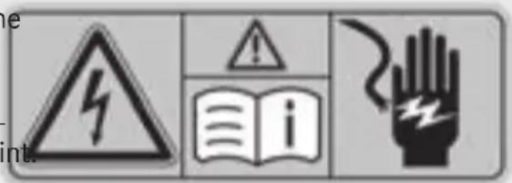
differ components of the hybrid drive system are illus marked with yellow warning stickers that warn you of the danger of high voltage. The cables for the vehicle's high-voltage electrical system are syangas in color.
Always have all work on the hybrid drive syste carried out at a qualified specialist workshop.
An authorized Mercedes-Benz Center is a qualified specialist workshop.
Book Vehicles with an electric motor generate much less driving noise than vehicles with internal combustion engines. As a result, your vehicle may not be heard by other road users in certain situations. This can happen, for example, when you are parking and your vehicle is not seen in other road users. This requires you to adopt a particularly anticipatory driving style, as it is necessary to allow for the possibility that other road users may behave erratically. oper-
Hybrid drive system
text_image
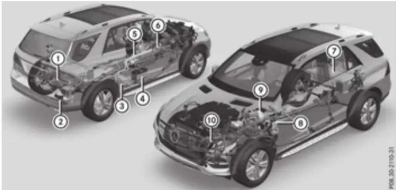
Technical diagram of a car showing internal components with numbered labels for identification.① Battery charger and voltage converter
② Vehicle socket
③ Power electronics
④ 12 V battery
⑤ High-voltage electrical system cables
⑥ Transmission with electric motor
⑦ High-voltage battery
⑧ Electric heater
⑨ Recuperative Brake System
⑩ Electric refrigerant compressor
You can switch off the hybrid drive system manually. For further information on the high-voltage switch-off device, see page 10).
Instrument cluster
text_image
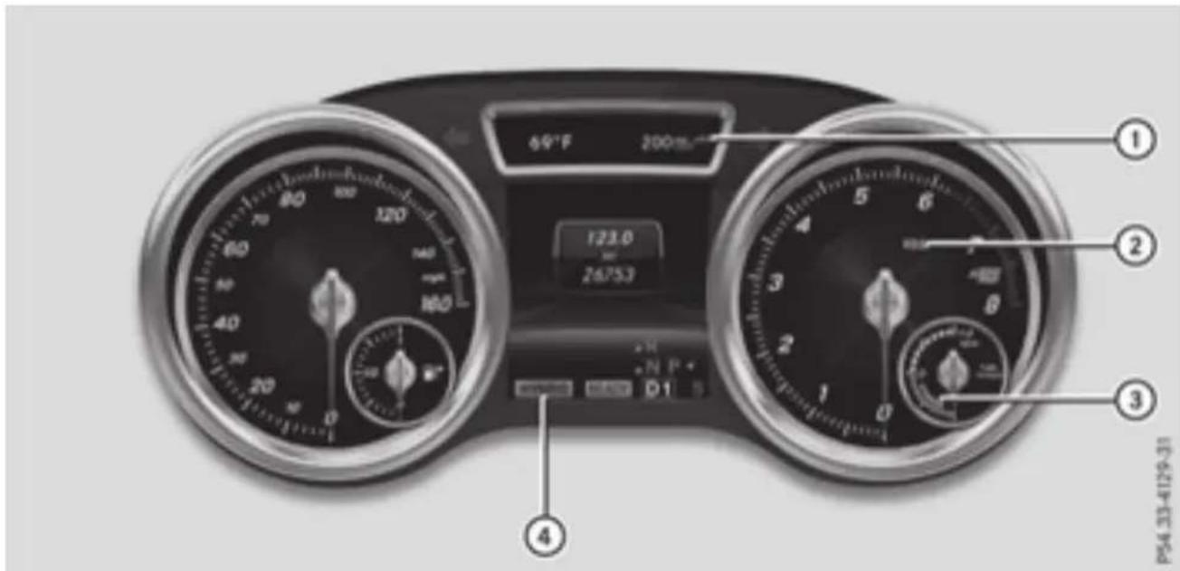
60°F 200m 123.0 26753 N P+ D1 ① ② ③ ④ PS4 33-4129-31① Electrical range
② Recuperative Brake System warning lamp (▷ page 49)
③ Electric motor performance display (▷ page 38)
④ Driving mode display (▷ page 21)
Hybrid drive system
General notes
Hybrid technology combines a fuel efficient internal combustion engine with a powerful electric motor.
Important safety notes
Danger of electric shock

DANGER
The vehicle's high-voltage electrical system tem is automatically deactivated. under high voltage. If you modify component the hybrid drive system is not activated when in the vehicle's high-voltage electrical system the vehicle is started if: or touch damaged components, you may be an electrical short circuit is detected in the electrocuted. The components in the vehi- hybrid drive system cle's high-voltage electrical system may be an electrical connection in the hybrid drive damaged in an accident, although the damage system is disconnected is not visible. There is a risk of fatal injury This ensures that you do not come into contact Following an accident, do not touch any high- with high voltage.
voltage components and never modify the vehicle's high-voltage electrical system. Have the vehicle towed away after an accident the vehicle's high-voltage electrical system checked by a qualified specialist workshop.
When towing a vehicle after an accident, be sure to observe the following sections in the vehicle Operator's Manual:
- Transporting the vehicle
- Towing the vehicle with the rear axle raised
- Towing a vehicle with both axles on the ground
Read the safety instructions on towing and starting ( page 53).

text_image
Warning symbol image showing hazard, warning sign, open book, and hand with lightning boltP08.00-2054-31
All components of the hybrid drive system are marked with yellow warning stickers that warn you of the danger of high voltage. The cables of the vehicle's high-voltage electrical system are orange in color.
The ignition must be switched off when carrying out general tasks, such as changing bulbs or checking the coolant level.
Automatic switching off of the hybrid drive system
If components of the restraint system are activated during an accident, the hybrid drive system is automatically deactivated.
The hybrid drive system is not activated when the vehicle is started if:
be an electrical short circuit is detected in the hybrid drive system
- an electrical connection in the hybrid drive nage system is disconnected
This ensures that you do not come into contact with high voltage.
Manual switching off of the hybrid drive system and
The hybrid drive system can be deactivated. manually using the high voltage switch-off device.
be sure vehicle to prevent damage to the hybrid drive sys- tem please observe the following instruc- tions:
- only deactivate the hybrid drive system manually in the following situations.
- work on the hybrid drive system may only be carried out at a qualified specialist workshop, even when it has been deactivated manually.
Deactivate the hybrid system manually if:
- the restraint system warning lamp in the instrument cluster lights up after an accident
- the vehicle is badly damaged, e.g. after an accident, and the restraint system components were not activated
- the vehicle is badly damaged and has to be towed or transported
▶ If possible, move the vehicle out of the danger zone: shift the automatic transmission into position N.
▶ Release the electric parking brake.
▶ Roll the vehicle to a safe place and park safely.
Get assistance from others if necessary.
critical value. In this case flammable gas escapes through a ventilation valve on the underbody. The gas can ignite. There is a of injury.
Leave the danger zone immediately. Secure the danger area at a suitable distance, whilst observing legal requirements.
The vehicle is locked automatically when the ignition is switched on and the wheels are ing. There is therefore a risk of being locke if the vehicle is being pushed or tested on dynamometer.
▶ Switch the ignition off.
▶ Shift the automatic transmission to park tion P.
Apply the electric parking brake.
Safeguard the vehicle against rolling away (see the vehicle Operator's Manual).
turn- ed out WARNING
In Ifa the housing of the high-voltage battery has been damaged, electrolyte and gases may leak out. These are poisonous and caustic. There is a risk of injury.
Avoid contact with skin, eyes or clothing. Immediately rinse electrolyte splashes off with water and seek medical attention straight away.
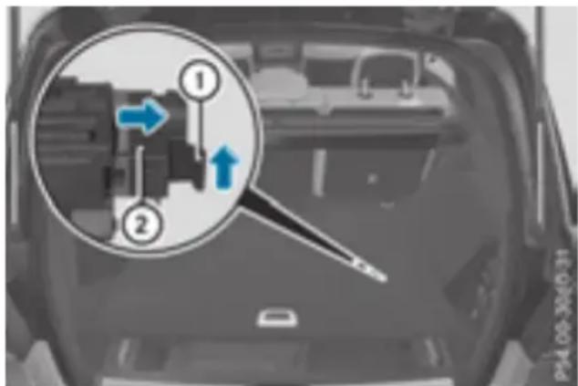
▶ To use the high-voltage switch-off device: open the tailgate.
▶ Lift the cargo compartment floor upwards (see the vehicle Operator's Manual).
▶ Pull off the right-hand paneling in the cargo compartment.
text_image
Diagram showing a mechanical component with numbered parts and directional arrows, likely from an engine or control system.! Exhaustive discharge caused by the vehicle standing idle for lengthy periods can damage the high-voltage battery. If the vehicle is idle for lengthy periods leave the high-voltage battery connected to a charging station.
Charging the high-voltage batterypage 29).
Engine compartment
Before opening the hood:
▶ Apply the electric parking brake.
▶ Shift the transmission to position P.
▶ Switch the ignition off.
▶ Observe the warning notes on the risk of electric shock ▷(page 10).
▶ Observe the warning notes on the hood (see the vehicle Operator's Manual).
▶ Press release clip ① in the direction of arrow and pull it out.
▶ Pull high-voltage switch-off device ② apart until it engages.
If the hybrid drive system has been deactivated
due to reasons mentioned above, have it checked at a qualified specialist workshop before reactivation.
High-voltage battery
RBS driving safety system (Recuperative Brake System)
The Recuperative Brake System supports you when braking with an electronically-controlled brake boost mode and enables the recovery of kinetic energy (recuperation).
Further information about the Recuperative Braking System▷(page 20).

WARNING
In the event of a vehicle fire, the internal pressure of the high-voltage battery can exceed a
Occupant safety
Restraint system warning lamp
If the restraint system is disrupted, the high-voltage on-board electrical system may not be switched off in the event of an accident as intended.

DANGER
If the restraint system is malfunctioning, restraint system components may be triggered unintentionally or may not deploy as intended during an accident. This can affect for example the Emergency Tensioning Device or the air bag. Furthermore, in the event of an accident, the vehicle's high-voltage electrical system may not be deactivated as intended. You may be electrocuted if you touch the damaged components of the vehicle's high-voltage electrical system. This poses an increased risk of injury or even fatal injury.
Have the restraint system checked and repaired in a qualified specialist workshop as soon as possible. After an accident, switch off the ignition immediately and remove the key from the ignition lock.
A malfunction has occurred if the restraint system warning lamp:
- does not light up after the ignition is switched on
- does not go out after a few seconds while the combustion engine or hybrid system is running
- lights up again while the combustion engine or hybrid system is running
Overview of climate control systems
General notes
Observe the notes and the recommended settings in the vehicle Operator's Manual. The w could otherwise fog up.
Climate control regulates the temperature and air humidity in the vehicle interior. Due to trical refrigerant compressor, the "Cooling with dehumidification" function is also operational out the combustion engine running. Optimum climate control is only achieved with the side and roof closed.
The residual heat function can only be activated or deactivated with the ignition switched (▷ page 17).
The "Pre-entry climate control" function is available. Use this function to briefly preheat or the driver's seat area or the entire vehicle interior before entering the vehicle. The air fro vents can also be pre-cooled.
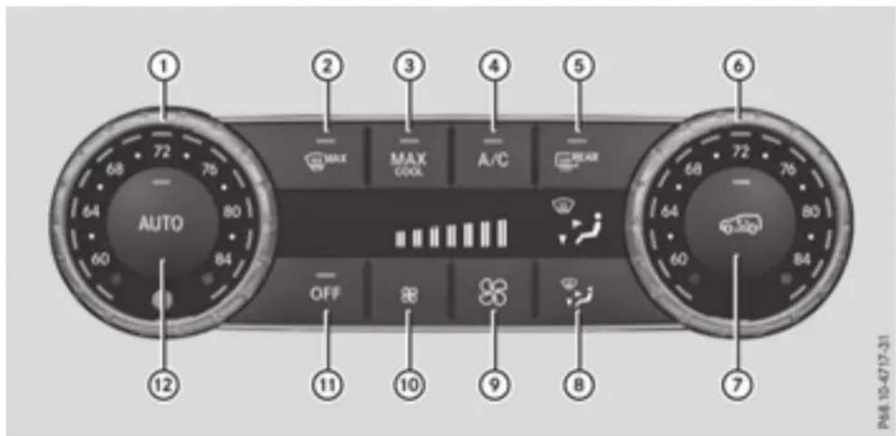
Control panel for dual-zone automatic climate control
text_image
1 2 3 4 5 6 MAX MAX COOL A/C REAR AUTO 68 72 75 64 80 60 84 12 OFF 11 10 9 8 7 P68.10-4717-31USA only
Front control panel
① Sets the temperature, left
② Defrosts the windshield
③ Switches the maximum cooling MAX COOL on or off
④ Switches cooling with air dehumidification on/off (▷ page 17)
⑤ Switches the rear window defroster on/off
⑥ Sets the temperature, right
⑦ Switches air-recirculation mode on/off
⑧ Sets the air distribution
⑨ Increases the airflow
⑩ Reduces the airflow
⑪ Activates/deactivates climate control
⑫ Sets climate control to automatic
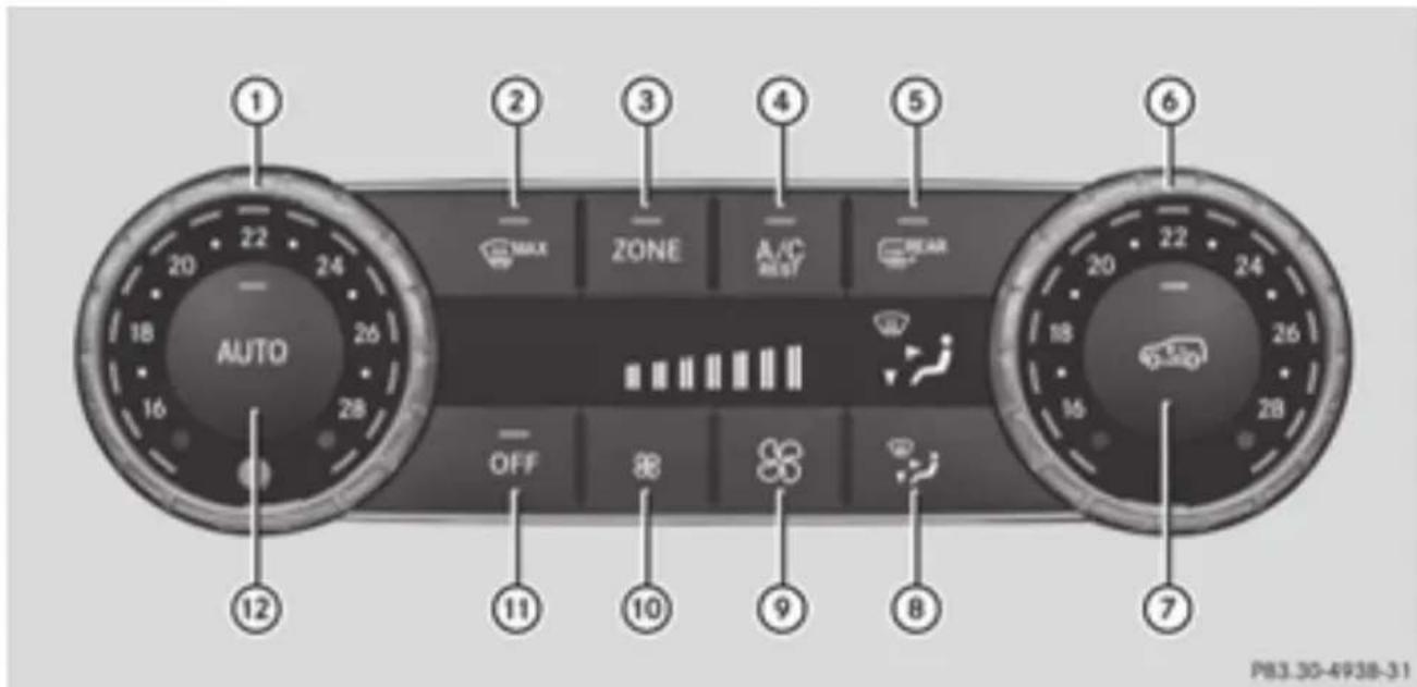
text_image
1 2 3 4 5 6 AUTO ZONE A/C RENT WEAR OFF 10 9 8 7 P83.30-4938-31Canada only
Front control panel
① Sets the temperature, left
② Defrosts the windshield
③ Switches the ZONE function on/off
④ Switches cooling with air dehumidification on/off (▷ page 17)
Switches the residual heat on or page (17)
⑤ Switches the rear window defroster on/off
⑥ Sets the temperature, right
⑦ Switches air-recirculation mode on/off
⑧ Sets the air distribution
⑨ Increases the airflow
⑩ Reduces the airflow
⑪ Activates/deactivates climate control
⑫ Sets climate control to automatic
In the vehicle Operator's Manual, information and recommendations can be found on:
• using automatic climate control
• using the rear control panel
• the individual functions
Observe these notes for optimal use of the automatic climate control.
The "Cooling with air dehumidification" function is even available when the engine is not runr (▷ page 17).
Use the residual heat function if you want to heat or ventilate the vehicle interior when the is switched off. The residual heat function can only be activated or deactivated with the igni switched off. When the ignition is switched on, the residual heat function is switched off (▷ page 17).
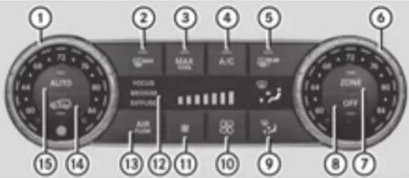
Control panel for 3-zone automatic climate control
text_image
① AUTO MAX A/C ② MINI AIR OFF ③ MINI A/C ④ MINI AIR OFF ⑤ MINI A/C ⑥ MINI AIR OFF ⑦ MINI AIR OFF ⑧ MINI AIR OFF ⑨ MINI AIR OFF ⑩ MINI AIR OFF ⑪ MINI AIR OFF ⑫ MINI AIR OFF ⑬ MINI AIR OFF ⑭ MINI AIR OFF ⑮ MINI AIR OFF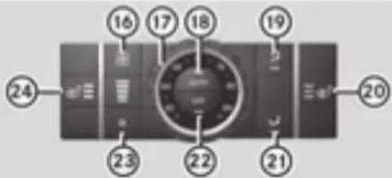
text_image
16 17 18 19 20 24 23 22 21PB3.40-5029-31
USA only
Front control panel
① Sets the temperature, left
② Defrosts the windshield
③ Switches the maximum cooling MAX COOL on or off
④ Switches cooling with air dehumidification on/off (▷ page 17)
⑤ Switches the rear window defroster on/off
⑥ Sets the temperature, right
⑦ Switches the ZONE function on/off
⑧ Activates/deactivates climate control
⑨ Sets the air distribution
⑩ Increases the airflow
⑪ Reduces the airflow
⑫ Display
⑬ Adjusts the climate mode settings
⑭ Switches air-recirculation mode on/off
⑮ Sets climate control to automatic
Rear control panel
⑯ Increases the airflow
⑰ Sets the temperature
⑱ Sets rear-compartment climate control to automatic
⑲ Directs the airflow through the rear air vents
⑳ Switches the seat heating on the right-hand side on/off
②1 Directs the airflow through the footwell vents
②2 Switches the rear climate control on/off
②3 Reduces the airflow
②4 Switches the seat heating on the left-hand side on/off
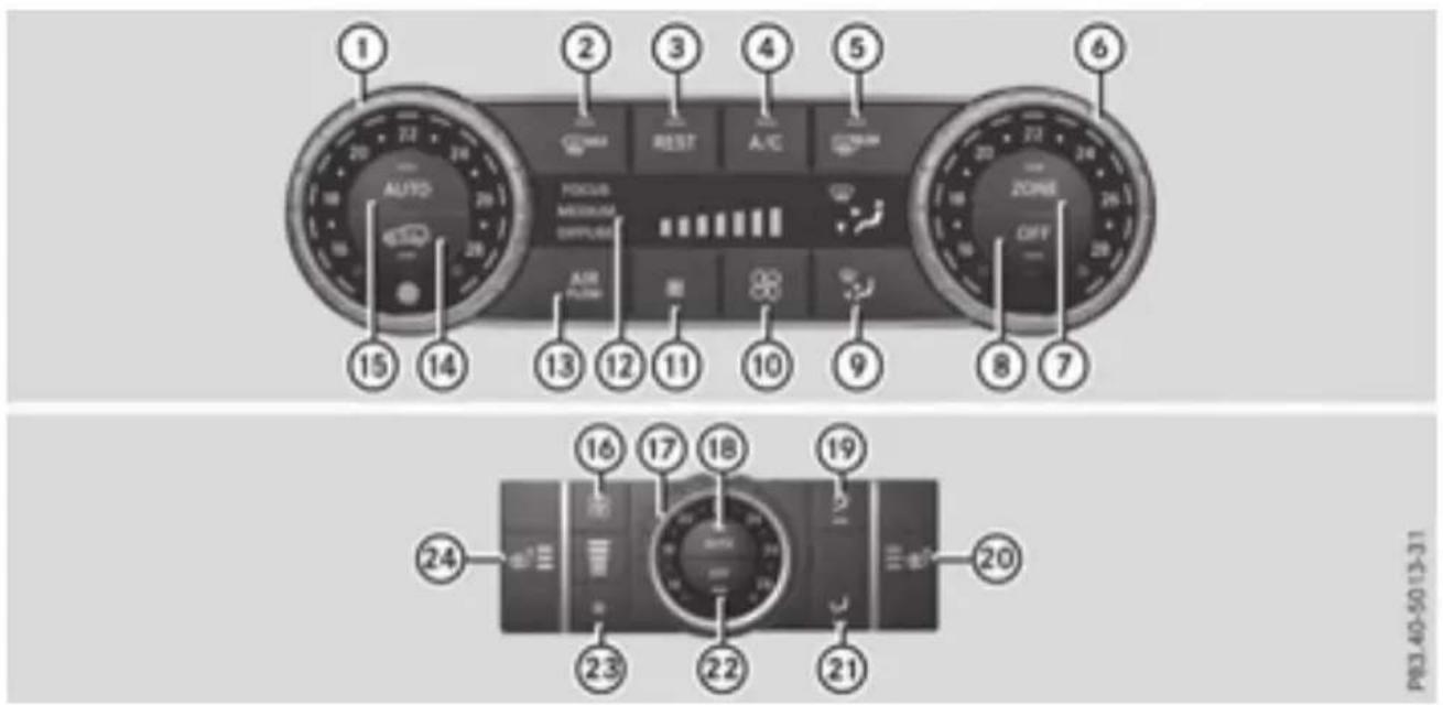
text_image
Diagram of a car dashboard with numbered UI elements and labeled controls for air traffic management.Canada only
Front control panel
① Sets the temperature, left
② Defrosts the windshield
③ Switches the residual heat on or off (▷ page 17)
④ Switches cooling with air dehumidification on/off (▷ page 17)
⑤ Switches the rear window defroster on/off
⑥ Sets the temperature, right
⑦ Switches the ZONE function on/off
⑧ Activates/deactivates climate control
⑨ Sets the air distribution
⑩ Increases the airflow
⑪ Reduces the airflow
⑫ Display
⑬ Adjusts the climate mode settings
⑭ Switches air-recirculation mode on/off
⑮ Sets climate control to automatic
Rear control panel
⑯ Increases the airflow
⑰ Sets the temperature
⑱ Sets rear-compartment climate control to automatic
⑲ Directs the airflow through the rear air vents
⑳ Switches the seat heating on the right-hand side on/off
②1 Directs the airflow through the footwell vents
②2 Switches the rear climate control on/off
②3 Reduces the airflow
②4 Switches the seat heating on the left-hand side on/off
In the vehicle Operator's Manual, information and recommendations can be found on:
• using automatic climate control
• using the rear control panel
• the individual functions
Observe these notes for optimal use of the automatic climate control.
The "Cooling with air dehumidification" function is even available when the engine is not r (▷ page 17).
Use the residual heat function if you want to heat or ventilate the vehicle interior when is switched off. The residual heat function can only be activated or deactivated with the switched off. When the ignition is switched on, the residual heat function is switched off (▷ page 17).
Operating the climate control systems
Switching cooling with air dehumidification on/off
▶ To activate: press the REST or A/C button. The indicator lamp in the REST or A/C buttc lights up.
To deactivate: press the REST or A/C rest button.
The indicator lamp in the REST or A/C REST buttc
If you deactivate the "Cooling with air-dehumid goes out.
ification" function, the air inside the vehicle_,will
not be cooled. The air inside the vehicle will also not be dehumidified. The windows can fog up the airflow setting.
more quickly. Therefore, deactivate the cooling function you activate the residual heat function at high with air-dehumidification function only briefly. temperatures, only the ventilation will be activated. The "Cooling with air dehumidification" function
is available even when the engine is not residual heat is deactivated automatically: The air inside the vehicle is cooled and debu after approximately 30 minutes modified according to the temperature selected, when the ignition is switched on
Condensation may drip from the underside of if the battery voltage drops the vehicle when it is in cooling mode. This is normal and not a sign that there is a malfunction.
▶ To activate: press the A/C or A/C button. The indicator lamp in the A/C or A/C button
lights up.
▶ To deactivate: press the A/C or A/C rest but-
ton.
The indicator lamp in the A/C or A/C REST goes out. The "Cooling with air dehumid
tion" function has a delayed switch-off feature.
General notes
Before getting in, the vehicle interior can be buttonly warmed or ventilated in advance and the fan-from the air vents can be pre-cooled.
The high-voltage battery must be sufficiently charged before "Pre-entry climate control via SmartKey" can be activated.
When the vehicle is pre-cooled, the following
offnctions are activated if required:
Switching the residual heat on or
Climate control system heat of
It is possible to make use of the residual heat of the engine to continue heating the stationary Blower vehicle for up to 30 minutes after the engine. She's ventilation been switched off. The heating time depends on the set interior temperature.
When the vehicle is pre-heated, the following functions are activated if required:
• Climate control system
- Blower
- Seat heating
If you have activated ionization via the dia system, it is activated together with entry climate control.
Activating/deactivating
Before "Pre-entry climate control via SmartKey" Seat ventilation (ventilation) can be activated, you must activate the function ionization using the on-board computer.
To activate: unlock the vehicle with the SmartKey or KEYLESS-GO.
The climate control functions are activated for up to 5 minutes for pre-heating and pre-cooling.
▶ To deactivate: "Pre-entry climate control via time SmartKey" deactivates automatically when the engine is started.
The following functions remain active after the engine is started:
- Seat heating (heating)
Problems with "Pre-entry climate control via SmartKey"
| Problem | Possible causes/consequences and ▶ Solutions |
| "Pre-entry climate control via SmartKey" can not be switched on or has switched itself off. | The condition of charge of the high-voltage battery is under the specified minimum condition of charge.► Start the engine when the vehicle is at a standstill.The engine powers the electric motor. The electric motor operates as a generator. The high-voltage battery is being charged.Further information on charging the high-voltage battery via:a mains socket (▷ page 31)a charging station (▷ page 35)a wallbox (▷ page 34) |
| "Pre-entry climate control via SmartKey" has been started more than twice with the engine switched off.► Switch on the engine and let it run for more than ten seconds.► Try again to switch on "Pre-entry climate control via SmartKey". |
Pre-entry climate control at time departure
Important safety notes

WARNING
If persons, particularly children are subject to prolonged exposure to extreme heat cold, there is a risk of injury, possibly fatal. Never leave children unattended in vehicle.
of General notes
You can use the "Pre-entry climate control at departure time" function to cool or heat the vehicle interior if the engine is not running. The "Pre-entry climate control at departure time" function can be activated regardless of whether or not the vehicle is connected to an electric power supply. The condition of charge of the high-voltage battery must be higher than the specified minimum condition of charge, however.
When the vehicle is connected to an electric power supply, priority is given to charging the high-voltage battery to the specified minimum charge. "Pre-entry climate control at departure time" is only activated subsequently.
The running time of the "Pre-entry climate computer. Activate or deactivate "Pre-entry clitrol at departure time" function may be reduced control at departure time" using the if: Mercedes connect me web App http://
www.mercedes.me.
- the vehicle is not connected to an electric
power supply and
• the high-voltage battery is not fully charged
With active "Pre-entry climate control at de
ture time" the condition of charge of the
voltage battery can be reduced, even if th
charge cable connector is connected.
When the vehicle is cooled, the following tions are activated if required:
The "Pre-entry climate control at departure time" function switches off automatically when the vehicle is started. The following functions
remain active:
e• Seat heating
- Seat ventilation
unponization
To deactivate "Pre-entry climate control at departure time": the activated "Pre-entry climate control at departure time" can be deactivated using the buttonpage 19).
• Climate control system
- Blower
- Seat ventilation
When the vehicle is heated, the following func-
tions are activated if required:
• Climate control system
- Blower
- Seat heating
If you have activated ionization via the dia system, it is activated together with entry climate control".
Information on activating or deactivating entry climate control at departure time" the multimedia system (see the vehicle tor's Manual).
Setting the departure time
You can set the departure time using the on-board computer or via the online access to the vehicle. The activation of the "Pre-entry climate control at departure time" function can be linked to this departure time. Your vehicle will then be cooled or heated until the desired temperature is reached in time for the set departure time. "Pre-entry climate control at departure time" will be activated a maximum of 55 minutes before. departure. If the departure is delayed, the ve cle will be heated or cooled for another five minutes.
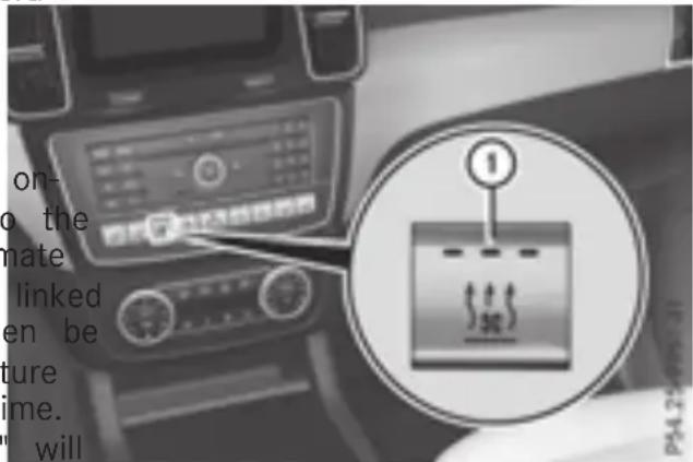
Activating/deactivating the "Immediate pre-entry climate control" function using the button
You can activate "Immediate pre-entry climate control" even if the vehicle interior is already a "Pre" the desired temperature. This means, for example, that the vehicle interior continues to be cooled or heated if the journey is interrupted from using up to 50 minutes and the interior temperature kept constant.
text_image
on- to the mate linked en be ture ime. willTo activate or deactivate "Immediate pre-veh-entry climate control": press button ①.
The blue or red indicator lamp in the button lights up or goes out.
The colors of the indicator lamps on button ① have the following meanings:
/•/blue: cooling activated
- red: heating activated
- yellow: departure time is preselected
te
▶ To set the departure time: set the departure
time using the on-board computer
(▷ page 44). Set the departure time using
the Mercedes connect me web App http://blue: cooling activated
www.mercedes.me.
▶ To activate or deactivate "Pre-entry climate control at departure time": activate
or deactivate "Pre-entry climate control at departure time" using the on-board com-
Driving
Points to remember
General notes
Hybrid technology combines a fuel efficient internal combustion engine with a powerful electric motor. In HYBRID mode, the hybrid drive system automatically selects the most cient operating mode for every driving situation. Drive the vehicle in the usual manner. To save fuel in HYBRID mode, the hybrid drive system switches off the combustion engine as often as possible during the journey when power output requirements are low. When power output requirements are low, the electric motor powers the vehicle. The engine is switched on, even while the vehicle is in motion, when a higher power output is required. The engine usually switched off when the vehicle is stationary. Consequently, there is usually no engine idling as with combustion engine vehicles.
For pulling away and accelerating, the elect motor supports the internal combustion engine using the power stored in the high-voltage battery. In addition, the power is used for electric driving, operation of the electric refrigerant compressor and to supply the 12 V on-board electrical system. In this way the hybrid system helps to reduce your vehicle's fuel consumption.
Observe the driving tips on plug-in hybrid operation ▶ page 26).
Recuperative Brake System
If you release the accelerator pedal when the vehicle is in motion, overrun recuperation tiated. The electric motor is operated as a generator when in overrun mode and when brake. Hybrid technology converts the kinetic energy of the vehicle into electricity and stores it in the high-voltage battery.
Observe the important safety notes for the Recuperative Brake System page 11).
Important safety notes
If the engine is switched off by the ECO start/stop function, you open the driver's door and unfasten your seat belt:
- a message appears in the multifunction display and
- a warning tone sounds
Feither information▷(page 45).
All of the vehicle's systems remain active, if:
• the vehicle is stationary
- the combustion engine is switched off and
- the READY indicator in the instrument cluster lights up
If you remove your foot from the brake pedal while in transmission position D or R, the vehicle may pull away automatically.
Observe the notes on the READY display of the ECO start/stop function page 23).
The vehicles with an electric motor generate much less driving noise than vehicles with internal combustion engines. As a result, your vehicle may not be heard by other road users in certain situations.
Depending on the vehicle's equipment and country-specific regulations, the vehicle can be equipped with Acoustic Vehicle Indication.
Acoustic Vehicle Indication generates a certain sound at a speed between 0 and 20 mph (30 km/h). This helps other road users, particularly pedestrians and cyclists, to hear your vehicle better. The sound can also be heard inside the vehicle.
The volume depends on the engine speed. The faster you accelerate, the louder the sound is. At a speed of over 20 mph (30 km/h) the sound is switched off. Above this speed, the natural sounds from the vehicle are sufficient that it can be heard in good time by other road users.
Operating modes
text_image
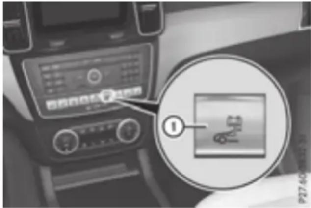
Car infotainment screen with control panel and magnified inset showing a floppy disk icon, labeled with number 1.Button ① allows you to choose between different operating modes.
▶ Press button ① to change the operating mode.
The operating mode selected appears in the instrument cluster▷(page 39).
If it is not possible to change operating modes, the display message change the current drive program before changing the operating mode, or Exit manual drive program M before changing the operating mode, appears in the multi-E-function display. Further information on "Display messages" ▷(page 45).
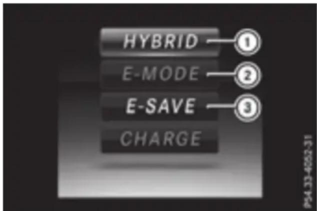
text_image
HYBRID E-MODE E-SAVE CHARGE① Operating mode selected
② Operating mode unavailable
③ Operating mode available
HYBRID
• Electric mode or driving with the internal combustion engine is possible
• Automatic selection of drive mode with electric mode as often as possible
- The high-voltage battery is discharged to approximately 15%.
- To subsequently maintain the condition of charge of the high-voltage battery, the electric output is reduced. All vehicle functions such as electric mode, energy recuperation or boost mode, for example, are still available.
- Purely electric operation until the performance limit of the electric motor is reached
E-MODE
E-SAVE
• Electric mode or driving with the internal combustion engine is possible
• Automatic selection of drive mode with electric mode as often as possible
- The current condition of charge of the high-voltage battery is maintained so the electrical energy can be used at a later time.
CHARGE
• Electric drive is not possible
- Charging the high-voltage battery while driving using the combustion engine
In the Sport drive program ( page 22) and during manual gearshifting (page 23), only the HYBRID operating mode is available.
If you switch from the Sport drive program to the Comfort drive program, the HYBRID operating mode remains selected.
If manual gearshifting is deactivated, the autodisplay, depress the brake pedal more firmly matic transmission shifts: and select the desired transmission position.
- into the drive program that was last selected. Release the brake pedal.
and
▶ Carefully depress the accelerator pedal. - into the driving mode that was last selected can find further information on pulling away. If you change the drive program, the operating the vehicle Operator's Manual.
mode that was last selected is stored for approximately 60 seconds. After this time, the HYBRID
operating mode is automatically activated.
Drive programs
Starting the engine
The vehicle starts in electric mode without internal combustion engine (noiseless start). The internal combustion engine starts only the power demanded by the driver exceeds available power that the electric motor can rently provide.
Noiseless start operation is dependent on the outside temperature and the operating temperature of the internal combustion engine. If conditions for noiseless start operation are filled, the vehicle starts with the internal combustion engine.
Observe the notes on starting in the vehicle further information on starting the engine in the Operator's Manual. vehicle Operator's Manual.
DYNAMIC SELECT controller
Select the drive program using the DYNAMIC SELECT controller. Depending on the drive program selected the following vehicle characters will change:
• the drive (engine and transmission manage-
chrent)
- the suspension
the steering.
not the all energy management
Each time you start the engine with the ignition
SmartKey or the Start/Stop button, the Comfort drive program is activated. You can find Further information on starting the engine in the vehicle Operator's Manual.
text_image
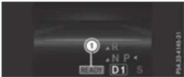
1 R N P READY D1 S P4.33-4149-31▶ Switch on the ignition.
▶ Depress the brake pedal.
▶ Start the vehicle (see the vehicle Operator's Manual).
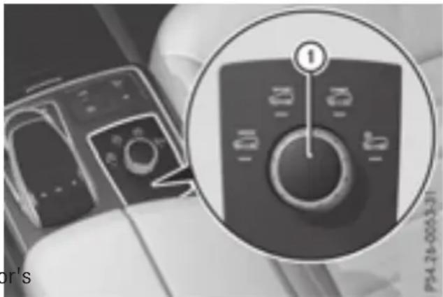
When the vehicle is operational, the READYTurn DYNAMIC SELECT controller ① as many indicator lights up in the multifunction displaces as necessary until the desired drive (▶ page 39). program is selected.
natural_image
Close-up of a computer control panel with an inset showing a dial indicator (no readable text or symbols)Pulling away
▶ Depress the brake pedal and keep it depressed.
▶ Shift the transmission to position D or R.
▶ If the Apply Brake to Shift from 'P' display message appears in the multifunction
The status icon of the selected drive program is shown in the multifunction display.
In addition, the current drive program settings are displayed briefly in the multimedia system display.
Available drive programs:
| Individual | · Individual settings |
| Sport | · Sporty driving style with increased boost mode· Electric-only operation is not possible |
| Comfort | · Comfortable, economical driving style· Electric-only operation is possible |
| Slippery | · Optimal driving characteristics on slippery or snow-covered roads· Electric-only operation is possible |
Further information on the drive program the vehicle Operator's Manual).
Using the steering wheel paddle shifters, you can temporarily change gears yourself. For further information on the manual drive program (▷ page 23).
Manual gear shifting
Using the steering wheel paddle shifters, y can temporarily change gears yourself. The transmission must be in position D. When activate manual gearshifting, the combustion engine is automatically switched on.
▶ To activate: pull the left or right steering wheel paddle shifter. Manual gearshifting is activated temporarily. The selected gear and M appear in the multifunction display.
The ECO start/stop function is not available when manually changing gear.
Further information on manual gearshifting the vehicle Operator's Manual).
ECO start/stop function
General notes
The ECO start/stop function switches the combustion engine off automatically when the cycle stops moving and at speeds below 80 (130 km/h)>(page 24).
All vehicle systems remain active, e.g. the automatic climate control.
The ECO start/stop function is neither available in the Sport drive program nor during manual shifting.
Automatic engine switch-off
The engine is switched off automatically, including when:
- the driver removes his/her foot from the accelerator in the Comfort drive program and a speed of 80 mph (130 km/h) is not exceeded ( page 24)
- the engine has reached its operating temperature
- the driver's seat belt is fastened and the driver's door is closed
- the driver only slightly depresses the accelerator pedal in order to, for example, maintain the current speed for a limited distance.
you the hood is closed and engaged properly. fur the high-voltage battery is charged sufficiently
- no malfunctions are present in the hybrid drive system
The internal combustion engine will not be switched off automatically, if:
- the self-diagnosis function of the engine man- you agement is active
- there is a malfunction in the hybrid drive system
g. the climate control of the vehicle requires it
• the high-voltage battery is charging (▷ page 40).
Automatic engine start
The automatically switched-off internal combustion engine starts automatically in certain situations, if:
- the power demand from the driver via the accelerator pedal is greater than the electric motor alone can provide
- the driver switches to the Sport drive program or to manual gearshifting
con the condition of charge of the high-voltage v battery has reached the lower limit
- mple driver has selected the CHARGE operating mode
Overrun mode
In overrun mode, the combustion engine is switched off and is disconnected from the train. The electric motor:
- generates low thrust, which corresponds to the overrun mode of an active combustion engine
- functions as a generator and produces the necessary energy for the auxiliary consumer and charges the high-voltage battery
Overrun mode is available in the Comfort program at speeds below 80 mph (130 k
The condition of charge of the high-voltage battery is thus systematically controlled. In addition, the control function takes into account drive that:
- the fuel saving through the use of electrical energy can vary, dependent on the route (e.g. urban, interurban or highway)
- the use of electrical energy is held available for electric driving, particularly for urban ers routes
The vehicle thus automatically selects the opti-drive driving mode for the respective section of the route.
The route-based operating strategy is available under the following conditions:
Route-based operating strategy
For the route-based operating strategy, the system factors in information about the expected route when route guidance is active.
The information on the route is provided by multimedia system and includes the following:
- road categories
- speed limitations
The use of electric energy is automatically spotially distributed from the beginning to the end of the journey, using information about the route. The distribution is pre-emptive and takes into consideration:
• the sections of the journey ahead
• the energy consumption on the whole route
• the Individual drive program is selected
say in the Individual drive program, the ECO set- edting is selected under Drive
• HYBRID driving mode is selected
• the active route guidance is activated
• suitable map data is available
When the route-based operating strategy is being used, the area in front of the vehicle is shown as green in the multifunction display.
Problems with HYBRID operation
Internal combustion engine
| Problem | Possible causes/consequences and ▶ Solutions |
| You cannot start the internal combustion engine. The multifunction display shows no display messages. The READY indicator in the multifunction display is off. | For example, self-diagnosis is not yet complete or the hybrid drive system is malfunctioning.▶Switch off the ignition and turn it back on.▶Try to start the internal combustion engine again.If the internal combustion engine still does not start:▶Consult a qualified specialist workshop. |
| You wish to pull away,The ECO start/stop function has failed. The warning and indicator but the ECO start/stop lamps in the instrument cluster light up. function does not start the internal combustion engine. The READY indicator in the multifunction display is off. | The ECO start/stop function has failed. The warning and indicator should shift the transmission to P.▶Shift off the ignition and turn it back on.▶Start the engine. |
| The hybrid drive system is malfunctioning.▶Consult a qualified specialist workshop. |
Recuperative Brake System
| Problem | Possible causes/consequences and ▶ Solutions |
| Braking resistance is reduced and brake pedal travel is longer than usual. | Risk of accidentThe Recuperative Brake System is malfunctioning.▶ Observe the additional display messages in the multifunction display ( page 45).▶ Observe the information regarding indicator and warning lamps in the instrument cluster ( page 49) . |
Hybrid drive system
| Problem | Possible causes/consequences and ▶ Solutions |
| The hybrid drive system has been switched off automatically. | You have been in an accident.The hybrid drive system remains switched off if:the internal combustion engine cannot be restarted after a few seconds.the red [icon] restraint system warning lamp in the instrument cluster is lit.Consult a qualified specialist workshop. |
| The hybrid drive system has been switched off automatically. The multifunction display also shows a display message. | An electrical short circuit has occurred in the hybrid drive system or electrical connection has been disconnected.Observe the additional display messages in the multifunction display (see the vehicle Operator's Manual).Consult a qualified specialist workshop. |
Driving tips
General driving tips
Drive carefully and maintain a safe distanceformed:
from the vehicle in front. Avoid frequent and
sudden acceleration as well as abrupt braking
During partial electric driving, pulling away a
acceleration, the electric motor supports the
internal combustion engine.
During overrun in transmission position D a
braking, the electric motor will operate as erator.
Further information on the ECO start/stop func-
tion ▶ page 23).
You can find further driving tips in the vehicle
Operator's Manual.
Stationary vehicle
If the vehicle is stopped, the combustion engine
is, for the most part, switched off. Automatic ^gen
climate control continues to function. The elec-
tromechanically assisted steering gear allows • whe
you to use the power steering without reduced comfort.
Acceleration
Depending on the operating mode, pulling away and driving under low load conditions are per-
• entirely by electric propulsion
• in combination with the internal combustion engine
When accelerating rapidly under increased or
full load, increased boost mode is utilized. The
electric motor supports the combustion engine
by providing additional drive torque.
Overrun mode or braking
There are three possible operating modes when the hybrid vehicle is decelerating:
- energy recovery takes place even when the vehicle is decelerating purely in overrun mode (I>page 20). The electric motor operates as a engine generator and stores the recovered energy in the high-voltage battery
- when the brakes are applied lightly, the vehicle is slowed down further by the electric motor. This increases the energy recovery taking place (page 20). The electric motor operates as a generator and stores the recovered energy in the high-voltage battery
- during heavy braking, the service brake is also used to slow down the vehicle. The two systems work together
Urban driving
In city traffic, energy is recuperated during quent deceleration phases.
The vehicle can be driven by the electric alone up to a speed of approximately 80 (130 km/h).
The vehicle is driven by the electric motor only when all conditions for the automatic engine switch-off are fulfilled.
Further information on the automatic engine switch-off ( page 23).
Driving on inter-urban roads
The following phases are possible when driving on inter-urban roads:
- rapid acceleration (boost mode)
- energy recuperation
• electric operation mode
The vehicle can be driven by the electric alone up to a speed of approximately 74 (120 km/h).
A great deal of recovered energy may be able, depending on the route profile. This reduces consumption and emissions.
Highway driving
When driving on a highway, switching off the combustion engine has a particularly positive effect on fuel consumption and emissions.
If the driver removes his/her foot from the accelerator pedal in the Comfort drive progr
and a speed of 80 mph (130 km/h) is not ded, the combustion engine is automatically switched off.
Further information on the automatic engine switch-off ▶ page 23).
Refueling
Refueling
General information
Observe the important safety notes under "Refueling" in the vehicle Operator's Manu
Pressure in the fuel tank must be released before refueling. Otherwise, the fuel filler flap cannot be opened.
If you unlock/lock the vehicle from the outside motor fuel filler flap also unlocks/locks.
The position of the fuel filler cap is displayed the instrument cluster. The arrow next to the filling pump indicates the side of the vehic
Preparing to refuel
▶ Switch off the engine.
▶ Remove the SmartKey from the ignition lock. or, on vehicles with KEYLESS-GO:
▶ Open the driver's door.
The vehicle electronics now have status being. This is the same as the SmartKey having been removed.
The driver's door can be closed again.
Opening the fuel filler flap (PLUG-IN motor HYBRID vehicles)
text_image
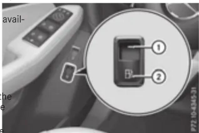
Diagram showing a device with labeled parts, including a circled inset highlighting two numbered components.▶ Pull switch ②.
Exceed Indicator lamp ① flashes and the please Wait Depressurizing Tank message appears in the multifunction display.
If the fuel filler cap is unlocked, indicator lamp ① lights up.
The Tank is Depressurized Ready for Refueling message appears in the multifunction display.
Please be sure to observe the information on refueling on the fuel filler flap.
There is a malfunction if:
- indicator lamp ① first flashes and then goes out
- the yellow engine diagnostics warning lamp lights up
From a speed of 1 mph (2 km/h), the filler flap can no longer be opened.
i The unlocking process for the fuel filler may take up to 15 minutes.
natural_image
Close-up of a car's door with a blue arrow icon and number 1, no visible text or symbols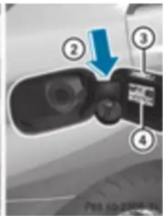
text_image
Diagram of a car's front camera with numbered parts and a blue arrow indicating the direction of motion or change.① To open the fuel filler flap
② To insert the fuel filler cap
③ Instruction label for fuel type to be refu
④ Tire pressure table
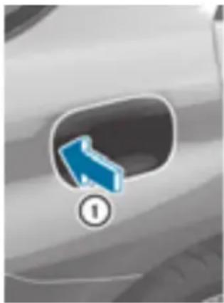
▶ Press the fuel filler flap in the direction arrow ①.
The fuel filler flap swings up.
▶ Turn the fuel filler cap counterclockwise remove it.
▶ Insert the fuel filler cap into the holder inside of the fuel filler flap.
▶ Completely insert the filler neck of the fuel pump nozzle into the tank, hook in place and refuel.
▶ Only fill the tank until the pump nozzle switches off.
Do not add any more fuel after the pump stop filling for the first time. Otherwise, fuel may leak out.
Closing the fuel filler flap
▶ Replace the cap on the filler neck and turn clockwise until it engages audibly.
▶ Close the fuel filler flap.
Close the fuel filler flap before locking the vehicle.
If you drive at speeds above 1 mph (2 km/h)
with the fuel filler flap open, the Filler Filler Flap Open message is shown in the multifunction display.
If you are driving with the fuel filler cap open, the reserve fuel warning lamp flashes. A message appears on the multifunction display.
In addition, the ☐ Check Engine warning lamp may light up.
Information on indicator and warning lamps in the instrument cluster (see the vehicle Operator's Manual).
Problems with the fuel tank
| Problem | Possible causes/consequences and ▶ Solutions |
| The fuel filler flap can be opened. | The fuel filler flap is not unlocked.▶ Unlock the vehicle (see the vehicle Operator's Manual).▶ Depressurize the fuel tank (▷ page 27). |
| The SmartKey battery is discharged or nearly discharged.▶ Unlock the vehicle using the mechanical key (see the vehicle Operator's Manual). | |
| The fuel filler flap is unlocked, but the opening mechanism is jamme▶ Consult a qualified specialist workshop. |
Charging the high-voltage battery
Important safety notes

DANGER
The vehicle's high-voltage electrical system under high voltage. If you modify components in the vehicle's high-voltage electrical system or touch damaged components, you may be electrocuted. The components in the vehicle's high-voltage electrical system may be damaged in an accident, although the dam is not visible. There is a risk of fatal injury. Following an accident, do not touch any high voltage components and never modify the vehicle's high-voltage electrical system. Have the vehicle towed away after an accident the vehicle's high-voltage electrical system checked by a qualified specialist workshop.

WARNING
In the event of a vehicle fire, the internal sure of the high-voltage battery can exceed critical value. In this case flammable gas escapes through a ventilation valve on the underbody. The gas can ignite. There is a of injury.
Leave the danger zone immediately. Secure the danger area at a suitable distance, whilst observing legal requirements.

DANGER
Connecting the charging cable to the mains supply via incorrectly installed mains sockets or by means of adapters, extension cables to similar could cause a fire or an electric shock. There is a risk of fatal injury.
To avoid hazardous situations, observe the following:
- Only connect the charging cable to mains sockets:
- which have been properly installed and - which have been inspected by a qualif electrician
- For safety reasons, only use the charging crash. cables supplied with the vehicle, or charg-
ing cables which have been approved for use with this vehicle.
- Never use a damaged charging cable.
- Do not use:
s - extension cables uts_ extension reels n - multiple sockets
- Never use socket adapters to connect the charging cable to the mains socket. The only exception being if the adapter has been tested and approved by the manufacturer for charging the high-voltage battery of an electric vehicle.
- Observe the safety notes in the operating instructions for the socket adapter.

DANGER
Connecting the charging cable to the vehicle via an incorrectly installed wallbox or by means of adapters, extension cables or similar could cause a fire or an electric shock. There is a risk of fatal injury.
To avoid hazardous situations, observe the following:
- Only connect the charging cable to a wall-box if: Ist the wallbox is properly installed
- the wallbox has been inspected by a qualified electrician
- the charging cable is not damaged.
Do not extend the charging cable. Do not use an adapter.
Always observe the safety notes in the wall-box's operating instructions.
The vehicle's high voltage electrical system is under high voltage.
Do not tamper with the high-voltage components or the orange cables of the high-voltage electrical system.
Do not touch high-voltage components or the orange cables of the high-voltage electrical system when a vehicle has been involved in
- Never touch damaged components or the imum power output of the high-voltage battery damaged orange cables of the high-voltages reduced by the vehicle. electrical system.
- Do not remove the covers of the high-voltage electrical system components that are marked with a warning sticker. Energy consumption and electrical range
The maximum electrical range is generally reduced by:
General notes
Method of operation
The vehicle is equipped with a high-voltage tery for driving. The high-voltage battery's the energy needed to operate the electric and releases it again.
The electric motor uses energy that has been a reduction in battery performance stored in the high-voltage battery when pulling away, accelerating and during the journey. • longer charge times
In overrun mode, kinetic energy is converted by means of energy recuperation into electrical Notes energy and stored in the high-voltage battery Information on overrun mode page 24).
The high-voltage battery can be charged as lows:
• through energy recuperation while the vehlong periods:
is in motion
- through the combustion engine while drivi in CHARGE operating modepage 21)
- with the relevant charging cable at an el cal outlet while the vehicle is stationary
- at a wallbox while the vehicle is stationary
- at a charging station while the vehicle is tionary
- check the condition of charge of the high-gvoltage battery more often
- connect the vehicle to a power supply
This prevents self-discharge and damage to the high-voltage battery.
The high-voltage battery can be charged in nominal voltage range from 100 V to 240
You can view the condition of charge of voltage battery in the multifunction display. Information about this can be found under "Energy flow display" page 40).
High and low outside temperatures
Low outside temperatures
At very low outside temperatures the maxin power output of the high-voltage battery may be reduced. The high-voltage battery is then no longer able to provide the normal electrical power output.
High outside temperatures
To prevent damage to the high-voltage battery due to very high outside temperatures, the max-
Avoid storing or transporting the vehicle at excessively high or low temperatures over a long period.
If you park the vehicle and leave it stationary for long periods:
^s Terms of use
Please note the information on exceptions and limitations in warranty documentation and in the Maintenance Booklet.
Handling the charging cable and charging cable controls
Always read the notes on the charging cable on the inside of the charge socket flap.
Do not leave the charging cable controls ( ≥ page 32) hanging loose from an electrical murn outlet. Otherwise, this could result in a poor ay be contact with the electrical outlet and malfunctions when charging the vehicle.
To ensure that the brackets within the chacable controls are not subjected to incorrect loads, observe the following:
General information about the charging procedure
- Never lift or carry the controls by the cable connector or the mains plug.
Pay attention to the "Important safety notes" charging (▶ page 29).
- To transport the charging cable, the cl cable can be:
The vehicle socket is located in the rear bump on the right below the tail lamp.
- wrapped around the controls or
The charge socket flap and the vehicle are centrally locked or unlocked simultaneously.
- secured to the housing of the controls
Heat generated by the charging cabl and charging cable connector
eCharging the high-voltage battery via the electrical outlet
Pay attention to the "Important safety notes" (▷ page 29).
^S Charging cable for electrical outlets
During the charging process, the charging c and charging cable connector may heat up.
The charging cable and the charging cable nector will only heat up within the permiss limiting values, provided that:
- the power supply and the charging cable not damaged
- the instructions for handling the charging cable and controls on the charging cable observed
If the charging cable or charging cable connec-
tor become too hot, have the mains power ply checked.
cable important safety notes
Only use the charging cable to charge the high-voltage battery. Do not use the charging cable for other purposes. It may otherwise be damaged.
The vehicle is supplied with a country-specific charging cable for connection to a mains socke. Only use the charging cable supplied with the vehicle or a charging cable approved for the vehicle.
i _sup -you use the supplied 12 A charging cable to charge a high-voltage battery:
• the charge time increases considerably
• electrical consumption increases considerably
Protection device against overvoltage
! Overvoltage in the mains supply may damage the vehicle. For this reason, the vehicle equipped with a protection device against overvoltage in the mains supply. This device may be triggered during severe thunder-
Where possible, charge the high-voltage battery at a charging station page 35). Only then can certified electrical energy consumption levels be reached.
storms, for example, and may lead to the charging process can vary depending on ding's fuse being tripped and an interruption the power supply. Therefore, always observe in the power supply. These functions protect the local information.
the vehicle. After the building fuse is switched on again, the charging process resumes automatically. Following an interruption in the (▷ page 34).
power supply or tripping of the building's fuse, Information on charging at a charging station it may take up to 10 minutes for charging to page 35).
resume automatically.
Switch on the building protection system after it has been triggered. Otherwise, the charging process cannot be continued.
Stowing the charging cable
The charging cable can be stowed and secured in the bag provided in the cargo compartment the vehicle.
Controls on the charging cable
text_image
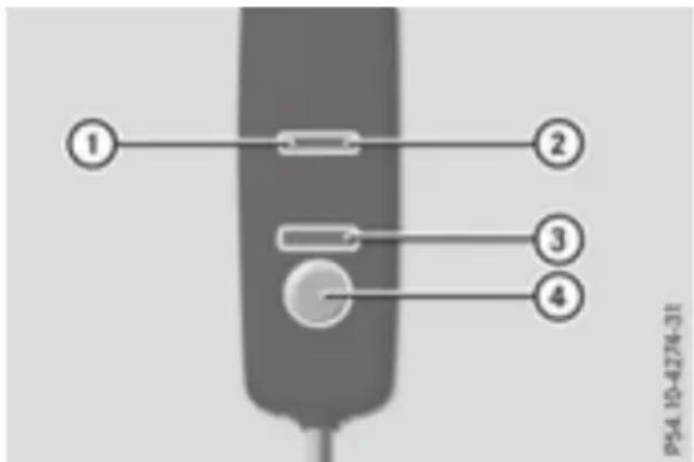
① ② ③ ④ P54.10-4274-31① On-board voltage indicator
② Protective and indicator system display
③ Charge current indicator
④ Charge current setting button
When displays ① and ② on the charging light up, this means the following:
Display ①
| Lights up green | The on-board voltage is connected. The high-voltage battery can be charged. |
| Flashes red | The power supply from the building is faulty. |
Display ②
| Lights up green | There are no malfunctions. The high-voltage battery can be charged. |
| Flashes red | The protective and indicator system has detected a malfunction due to an internal malfunction. The high-voltage battery cannot be charged. |
If the control detects residual current or a function, the charging process is halted. On the malfunction has been rectified the charge process is resumed automatically.
For information on problems relating to the charging process, see page 35).
external electrical system may overheat. There is a risk of fire.
Before beginning the charging process, check the maximum permissible charge current locally. Consult a qualified expert to do so where necessary.
If necessary, adjust your vehicle's settings.
! An excessive charge current can blow a fuse or lead to overheating of the external power supply. Check whether the external power supply is compatible with the set charge current. If necessary, lower the set charge current or use another power socket.
Before starting the charging process at a power socket, check the maximum permissible charge current for the relevant power socket or the cable building.
You can set the maximum permissible charge current:
• on the controls of the charging cable
- in the Settings menu of the on-board computer ( page 43)
The lower value of the two charge current settings - on the charge cable controls and in the on-board computer - determines the maximum charge current. If you cannot set the precise maximum permitted charge current, select the next lowest available value.
Only set the maximum permitted charge current in the on-board computer menu if:
- it is not possible to set the charge current on the charging cable
- the precise maximum permitted charge current can only be set via the on-board computer
How to set the maximum permissible charge current on the charging cable, is described as follows.
To adjust the setting: press button ④ repeatedly until the desired setting is selected in display ③.
- Two LEDs are flashing: minimum setting
- All LEDs are flashing: maximum setting
Setting the maximum charge current
WARNING
If the charge current draw via a mains socket is too high during the charging process, the

socket
If, after the charging process, the charging connecting the charging cable
is:
- left connected to the power socket, the currently selected values will be used for the next charging process.
- removed from the power socket, the values will be reset to the minimum setting for the next charging process. You may then need to reset the values of the maximum charge current.
If the vehicle requires more time than usual when charging, check the maximum charge current settings using the controls on the charging cable or in the on-board computer's menu.
Indicator lamp on the vehicle socket
When the indicator lamp on the vehicle socket lights up, this means the following:
| Indicator lamp | |
| Flashes orange | The connection between the vehicle and the current source is being established before charging begins. |
| Flashes green | The high-voltage battery is being charged. |
| Flashes red | A malfunction has occurred while charging.The indicator lamp goes o after approximately 90 seconds. |
| Lights up orange | A charging break for the voltage battery is taking place.The indicator lamp goes o after approximately 90 seconds. |
| Lights up green | The high-voltage battery is fully charged.The indicator lamp goes o after approximately 90 seconds. |
text_image
cur- ne next des the ed to cur- usual se ② ③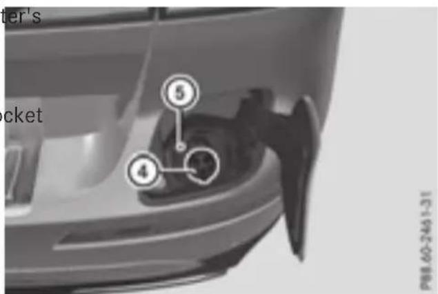
text_image
ter's cket ⑤ ④ P88-60-2461-31▶ Shift the transmission to position P.
▶ Switch the ignition off.
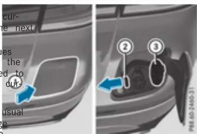
▶ Press the charge socket flap in the direction of arrow ①.
The charge socket flap swings up.
▶ Press fastener ② to the left.
Socket cap ③ is open.
▶ Insert the power supply plug into the electrical outlet to the stop.
Insert the charging cable connector into vehicle socket ④ to the stop.
Indicator lamp ⑤ first flashes orange and then green.
The high-voltage battery is being charged.
If the charging cable is connected to the vehic you cannot start the engine or move the vehic As soon as the charging process begins, you display the charging prediction of the settings on-board computer menu. The charging prediction is either the anticipated condition of charge at the programmed departure time or the time when the high-voltage battery will be fully
If the indicator lamp is off, lock or uncharged (page 44).
vehicle. The indicator lamp then displays current status of the charging process a
the
Depending on the temperature, the fan and battery cooling system may audibly switch on during the charging process.
Removing the charging cable
The high-voltage battery is fully charged wh
- the charge level display reaches 100% in multifunction display▶(page 40)
- the indicator lamp in the vehicle socket up green after unlocking or locking the
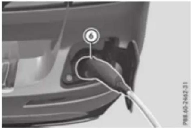
natural_image
Close-up of an electric vehicle charging plug with a cable, no visible text or symbols▶ Press and hold button ⑥ on the charging cable connector and remove the charging cable connector from the vehicle socket.
▶ Close socket cap ③.
▶ Close charge socket flap ①.
Remove the mains plug from the mains socket and safely stow away the charging cable inside the vehiclepage 31).
Charging the high-voltage battery from the wallbox
General notes
It is recommended that you charge your using a wallbox or at a charging station.
Make sure that the maximum charging currentThis high-voltage battery is being charged. not limited in the Sets menu of the on-board computer. You must select the maximum value if charging at a wallbox or a charging station (page 43). If the charging cable is connected to the vehicle, you cannot start the engine or move the vehicle. As soon as the charging process begins, you can
Pay attention to the "Important safety notes (▷ page 29).
Connecting the charging cable
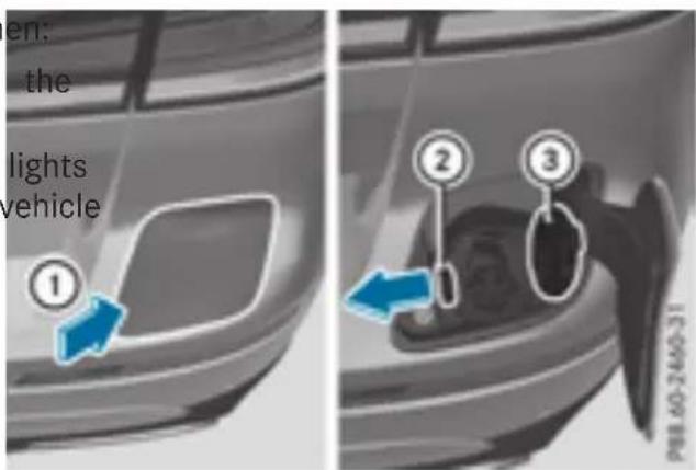
text_image
en: the lights vehicle ① ② ③ P81.60-2490-31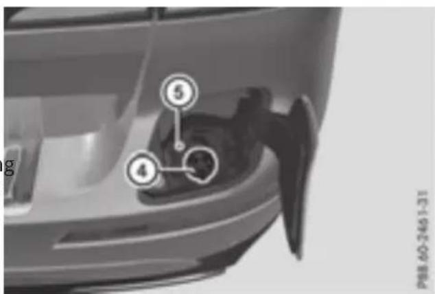
text_image
5 4 P88 60-2461-31▶ Shift the transmission to position P.
▶ Switch the ignition off.
▶ Press the charge socket flap in direction of arrow ①.
The charge socket flap swings up.
▶ Press fastener ② to the left. Socket cap ③ is open.
▶ Insert the charging cable connector into vehicle socket ④ to the stop. Indicator lamp ⑤ first flashes orange and then green.
This high-voltage battery is being charged. If the charging cable is connected to the vehicle, you cannot start the engine or move the vehicle. As soon as the charging process begins, you can display the charging prediction in the settings on-board computer menu. The charging prediction is either the anticipated condition of charge at the departure time set or the time when the high-voltage battery will be fully charged ( page 44).
Depending on the temperature, the fan and battery cooling system may audibly switch on during the charging process.
Removing the charging cable
The high-voltage battery is fully charged when cable
- the charge level display reaches 100% in multifunction display▶(page 40)
- the indicator lamp in the vehicle socket up green after unlocking or locking the
▶ Press and hold button ⑥ on the charging cable connector and remove the charging cable connector from the vehicle socket.
the Close socket cap ③.
▶ Close charge socket flap ①. lights
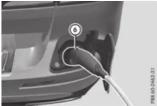
natural_image
Close-up of a car charging plug with a cable, no visible text or symbolsCharging the high-voltage battery at the charging station
Before beginning the charging process at a charging station without communication capabilities, you must first activate the station, e.g. using an RFID card. Observe the on-site operator instructions for the charging station.
The connection for the vehicle at a charging station is identical to the connection on a wallbox (▷ page 34).
Problems with the charging process
| Problem | Possible causes/consequences and ▶ Solutions |
| The charge socket flap cannot be opened. | The charge socket flap is not unlocked.▶ Unlock the vehicle (see the vehicle Operator's Manual).If the SmartKey battery is discharged:▶ Unlock the driver's door using the mechanical key (see the Operator's Manual).or▶ Unlock the vehicle centrally from the inside (see the vehicle's Manual). |
| The charge socket flap is unlocked, but the opening mechanism jammed.▶ Lock the vehicle and unlock it again.If, after that, the opening mechanism is still jammed:▶ Consult a qualified specialist workshop. |
| Problem | Possible causes/consequences and ▶ Solutions |
| The high-voltage battery is not being charged. | The indicator lamp on the vehicle socket flashes red.A malfunction has occurred during the initialization of the charging process or during charging.x Disconnect the charging cable connector from the vehicle socket and plug it back into the vehicle socket.If the problem persists:x Have the mains socket checked for correct function or use another mains socket.orx Use a different charging station.orx Consult a qualified specialist workshop. |
| The indicator lamp on the vehicle socket does not light up.No connection can be established between the vehicle and the external power source.x Connect the charging cable once again.If the problem persists:x Have the mains socket checked for correct function or use another mains socket.orx Use a different charging station.orx Consult a qualified specialist workshop. | |
| The charging cable con- nector cannot be removed from the vehi- cle socket. | The snap fastener on the charging cable connector is locked.x Press and hold the button on the charging cable connector. The snap fastener on the vehicle socket is unlocked.x Remove the charging cable connector from the vehicle socket.If the snap fastener on the charging cable connector is locked:x Press and hold the button on the charging cable connector and try to release the lock. |
Online access to the vehicle
General information
G WARNING
If you operate information systems and communication equipment integrated in the vehi cle while driving, you will be distracted from traffic conditions. You could also lose control of the vehicle. There is a risk of an accide
Only operate the equipment when the traffic situation permits. If you are not sure that this is possible, park the vehicle paying attention to traffic conditions and operate the equipment when the vehicle is stationary.
Operation of integrated information systems and communications equipment in to the vehicle: you must observe the legal denetquirements for the country in which you are currently driving.
You can call up remote query and remote Then-following functions can be accessed:
figuration functions for your vehicle using online
access to the vehicle. This is possible from Internet-enabled computer, as well as many modern smartphones.
- request the current condition of charge of the high-voltage battery
- program the departure time (▷ page 44)
- set or activate the "Pre-entry climate control at departure time" function (see the separate COMAND operating instructions)
Information on additional functions and operating instructions can be found within the online access to the vehicle.
Please call the Mercedes-Benz Customer Assistance Center (USA) at the hotline number 1-800-FOR-MERCedes (1-800-367-6372) to obtain the relevant Internet address.
Online access to the vehicle is restricted to the contractual periods of mbrace. Activated access to the mbrace emergency call system is required for use.
In order to be able to use online access vehicle, you must agree to the local terms use.
Further information about the supported end devices, available languages and contractual periods is available at any authorized Merce Benz Center.
In order to be able to call up online access vehicle, the vehicle must be connected to Internet ( page 37).
Connecting the vehicle to the Internet
to the
This function is not available in all countries and requires activated access to the mbrace emergency call system.
You can use the online access to the vehicle the vehicle has a connection to the Internet via mobile phone network. The necessary data is transmitted by radio. The vehicle automatically assesses to the recognizes whether a connection to the Internet is possible or not. No presets are necessary.
i Restrictions in reception are possible if the vehicle is in an underground car park, for example. Restrictions may also occur in areas with poor mobile network coverage.
Notes on data protection
Remember that online access to the vehicle offers access to your data.
i Prevent unauthorized persons from accessing this data.
Every person who has access to the inflation stated can use the functions of the access to the vehicle.
i Information when selling a vehicle or buying a used vehicle:
- If you sell your vehicle, you are obliged to delete the vehicle from your personal on the online access to the vehicle.
- If you have bought a used vehicle, it is able that the previous owner still has access to the online access to the ve
Parking
▶Apply the electric parking brake.
The red Ⓓ indicator lamp in the instrument cluster lights up.
▶ Use the DIRECT SELECT lever to shift the automatic transmission to P.
Switch the ignition off. The READY indicator in the instrument cluster goes out.
is pos-You can find further information on parking and switching off the combustion engine in the vehicle Operator's Manual.
Calling up functions
The online access to the vehicle allows you access to your vehicle's information and functions using remote query and remote configuration.
Important safety notes

WARNING
If you operate information systems and co-munication equipment integrated in the vehicle while driving, you will be distracted from traffic conditions. You could also lose control of the vehicle. There is a risk of an accident. Only operate the equipment when the traffic situation permits. If you are not sure that it is possible, park the vehicle paying attention to traffic conditions and operate the equipment when the vehicle is stationary.
You must observe the legal requirements for the country in which you are currently driving operating the on-board computer.

WARNING
If the instrument cluster has failed or malfunctioned, you may not recognize function restrictions in systems relevant to safety. Operating safety of your vehicle may be impaired. There is a risk of an accident.
Pull over as soon as it is safe to do so and consult a qualified specialist workshop.
The on-board computer only shows messages warnings from certain systems in the multifunction display. You should therefore make sure your vehicle is operating safely at all times.
For an overview, see the instrument panel illustration ( page 9).
You can find further information about operat the on-board computer in the vehicle Operator's Manual.
Displays and operation
Electric motor performance display
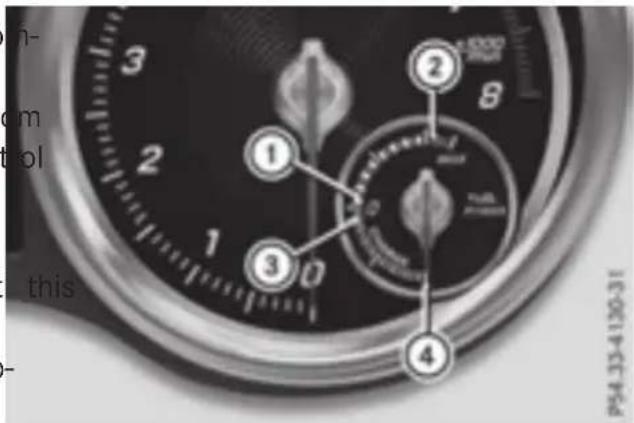
text_image
this P54.33-4.120-31The power display for the electric motor is located on the right-hand side of the instrument when cluster.
- Area ① to ② (E-DRIVE):
This shows the electric output from the electric motor, e.g. during electric operation or in boost mode.
The When the motor is switched on, the needle is at limit ①. With increasing pressure on the accelerator pedal the needle moves from ① to ②.
Driving with the electric motor: when the needle reaches limit ② the combustion engine is switched on. If the display
or approaches limit ② and you remove your foot from the accelerator pedal, the needle drops again. The combustion engine is not switched on. At low speeds, you can thereby control the electric operation usage so that you only drive in electric mode.
iDgiving with the combustion engine: the
electric motor supports the combustion engine by providing additional drive torque (boost mode) until the needle reaches limit ②.
You can also select the operating mode of the hybrid drive system> page 21).
- Area ③ to ④ (CHARGE):
This shows the recuperated energy which is stored in the high-voltage battery as electrical energy.
When the needle reaches limit ④, the maximum recuperative brang power has been reached. The mechanical brake is activated.
Coolant temperature gauge

WARNING
Opening the hood when the engine is over heated or when there is a fire in the end compartment could expose you to hot gas or other service products. There is a risk injury.
Let an overheated engine cool down before opening the hood. If there is a fire in the engine compartment, keep the hood closed and contact the fire department.
⑤ Drive program
⑥ Transmission position
Additional displays in the multifunction display:

EADY Vehicle operational (▷ page 22)

Operating mode, other operating mode splays page 21)

Electric range (▷ page 9)
Menus and submenus
Menu overview
! A display message is shown if the coolant temperature is too high.
If the coolant temperature is over 248 (120 °C), do not continue driving. The will otherwise be damaged.
Press the ◀ or ▶ button on the steering wheel to call up the menu bar and select a rF Operating the on-board computer (see the vehicle Operator's Manual).
The multifunction display shows the coolant temperature in the coolant submenu.
Under normal operating conditions and with the specified coolant level, the coolant temperature may rise to 248 °F (120 °C).
The following menus have been added to changed in order to include displays and settings for hybrid operation:
Multifunction display
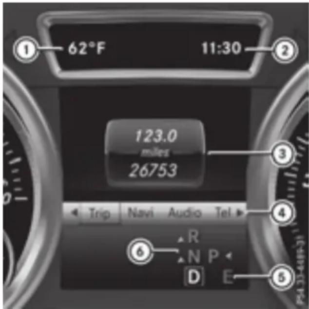
text_image
62°F 11:30 123.0 miles 26753 Trip Navi Audio Tel R N P D E• the Trip menu (▷ page 40)
- Energy flow display
- Displaying the current fuel consumption
- Displaying the total range and electrical range
- Trip computer "From Start" or "From Reset"
- Service menu
- Displaying the coolant temperature (▷ page 39)
- Settings menu (▷ page 43)
- Hybrid submenu for setting the maximum charge current and departure time for pre-entry climate control or the charging process ( page 43). In addition, the charging prediction for the current charging process is displayed.
- Instrument Cluster submenu for selecting the outside temperature or speed as the permanent display in the multifunction display ( page 44).
① Permanent display: outside temperature or speed ( page 44)
② Time
③ Text field
④ Menu bar
Trip menu
Energy flow display
Selecting the energy flow display in multifunction display
▶ Press the ◀ or ▶ button on the st wheel to select the iTmenu.
▶ Use ▼ or ▲ to select Energy Flow.
▶ Confirm by pressing OK on the steering wheel.
The active components of the hybrid driv system are highlighted in the energy flow play.
Overview
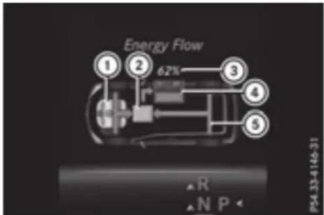
text_image
Energy Flow ① ② 6.2% ③ ④ ⑤ R N P P54.33-4146-31① Internal combustion engine
② Electric motor
③ High-voltage battery condition of charge
④ High-voltage battery
⑤ Energy flow
The active components of the hybrid drive tem are highlighted.
The energy flow is indicated by arrows. The arrows have a different color depending on operating state.
Automatic engine switch-off
natural_image
Top-down view of a car chassis with visible battery pack and roof structure (no text or symbols)The engine and electric motor are switched off. The arrows for the energy flow are not shown. The condition of charge of the high-voltage battery is shown when the SmartKey is in position: In the ignition lock.
Engine running while vehicle is stationary teething
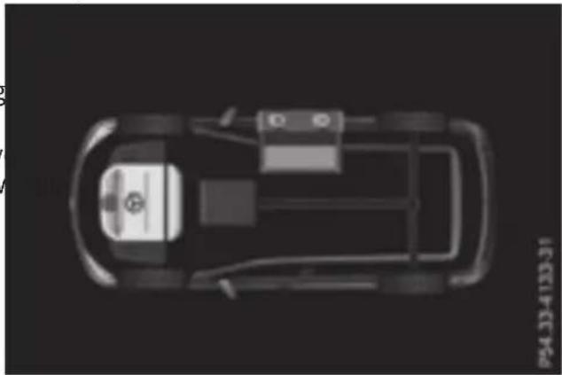
natural_image
Top-down view of a car chassis with visible suspension components and roof structure (no text or symbols)The combustion engine is running while the vehicle is stationary. The high-voltage battery is not being charged.
The arrows for the energy flow are not shown. The combustion engine is highlighted.
Charging while vehicle is stationary
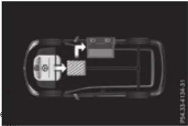
natural_image
Top-down schematic of a car's internal components, showing battery, wheels, and suspension system (no text or symbols)The engine powers the electric motor. The electric motor operates as a generator. The high-voltage battery is being charged.
The arrow representing energy flow is shown in white.
Driving using the engine
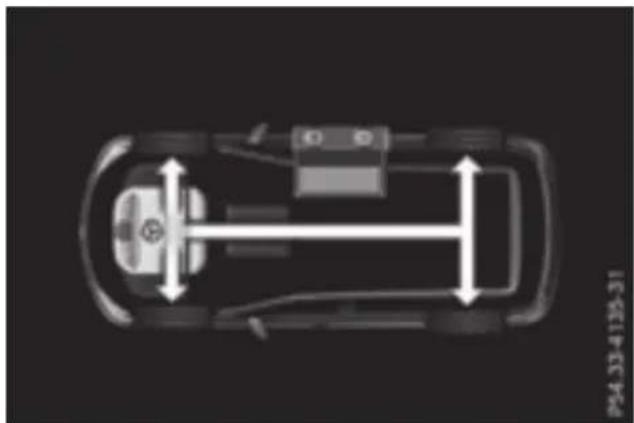
natural_image
Top-down schematic of a car showing internal components and height measurement (no text or symbols)The engine powers the vehicle.
The arrows for the energy flow are shown in white.
Driving using the engine plus boost m
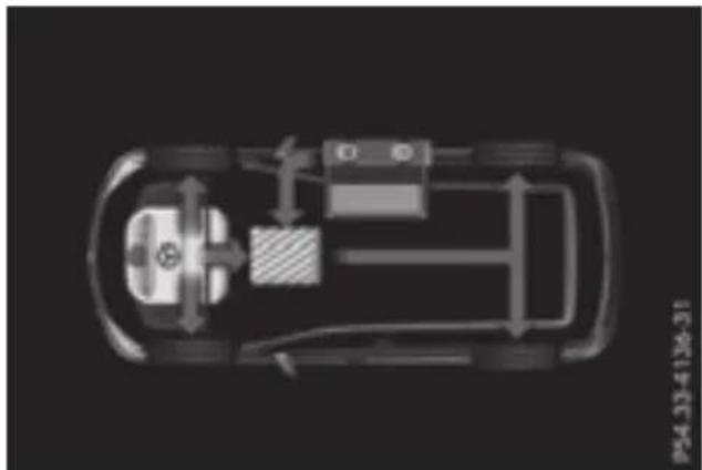
natural_image
Top-down schematic of a car showing internal components and airflow paths (no text or symbols)If you accelerate the vehicle rapidly, the electric motor supports the combustion engine by providing additional drive torque.
The arrows for the energy flow are shown in red.
Driving using the engine plus energy recovery
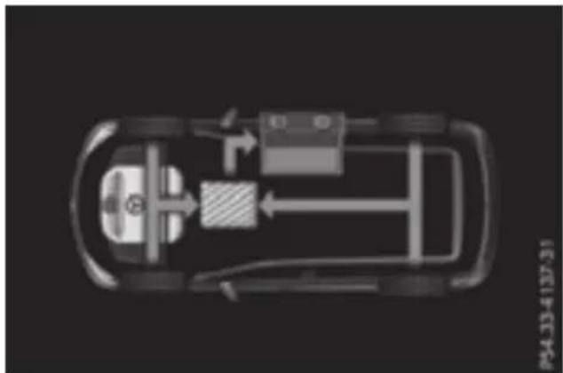
natural_image
Top-down schematic of an electric vehicle chassis showing battery, transmission line, and fuel components (no text or labels)The engine powers the vehicle. The electric motor is operating as a generator, e.g. in run mode and when braking page 24). The kinetic energy of the vehicle is converted into electrical energy. The high-voltage battery is being charged.
The arrows for the energy flow are shown in green.
Driving using the internal combustion engine and charging the high-voltage battery
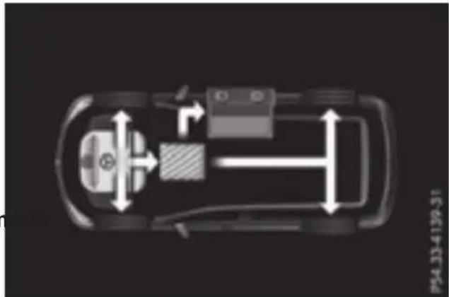
natural_image
Top-down schematic of a car showing internal components and directional arrows (no text or symbols)The engine powers the vehicle. The engine also powers the electric motor. The electric motor operates as a generator. The high-voltage battery is being charged.
The arrows for the energy flow are shown in white.
Driving using the internal combustion engine and discharging the high-voltage battery
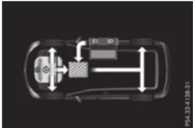
natural_image
Top-down diagram of a car showing internal components and directional arrows (no text or symbols)The engine powers the vehicle. If the vehicle is approaching a downhill gradient with a high potential for energy recuperation, the condition of charge of the high-voltage battery is intentionally kept low or intentionally reduced.
The arrows for the energy flow are shown in white.
Further information on the route-based operating strategy▶(page 24).
Electric operation mode
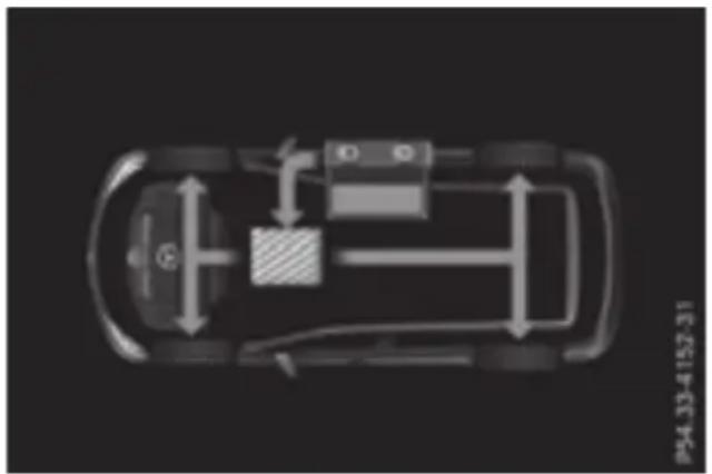
natural_image
Top-down schematic of a car showing internal components and directional arrows (no text or symbols)The electric motor powers the vehicle. The voltage battery supplies energy to the electric motor.
The arrows for the energy flow are shown green.
Electric operation mode and charging high-voltage battery

natural_image
Top-down schematic of a car showing internal components and airflow path (no text or symbols)The electric motor is operating as a general e.g. in overrun mode and when braking. The kinetic energy of the vehicle is converted in electrical energy. The high-voltage battery is being charged.
The arrows for the energy flow are shown green.
Charging the high-voltage battery when stationary
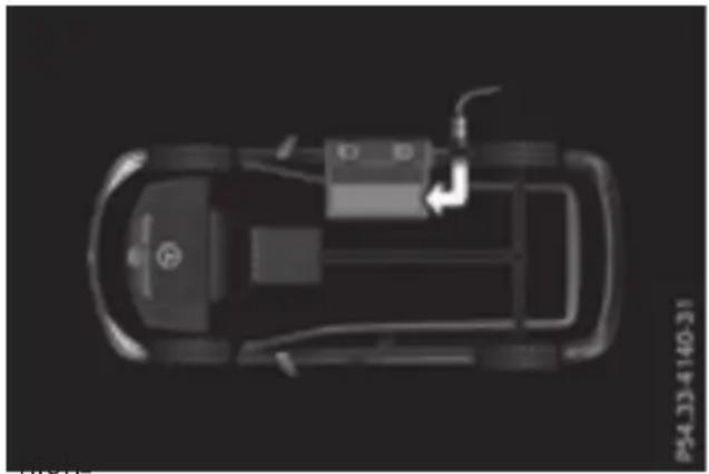
natural_image
Top-down schematic of an electric vehicle showing battery, motors, and wiring (no text or symbols)The engine and electric motor are switched off. The arrows for the energy flow are not shown. Further information on charging the high-voltage battery via:
the mains socket (▷ page 31)
- a charging station (▷ page 35)
- a wallbox (▷ page 34)
Displaying the current fuel consumption
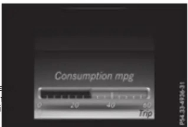
text_image
Consumption mpg 0 20 40 60 Trip P4.33-4726-31The menu displays the current fuel consumption.
▶ Press the ◀ or ▶ button on the steering wheel to select the iTmenu.
▶ Confirm by pressing OK on the steering wheel.
▶ Press the ▼ or ▲ button to select the display with the current fuel consumption.
You can also display the fuel consumption values and the electrical energy generated in the multimedia system display. The multimedia system shows the values from the last 15 minutes in a bar graphpage 50).
Displaying ranges
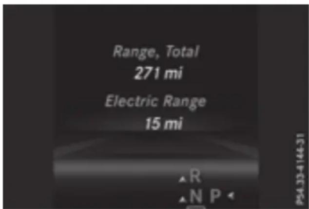
text_image
Range, Total 271 mi Electric Range 15 mi ▲R ▲N PThe approximate range is based on the current driving style.
▶ Press the ◀ or ▶ button on the steering wheel to select the Trip menu.
▶ Confirm by pressing OK on the steering wheel.
The approximate total range that can be ered is calculated according to your current driving style and the amount of fuel in the tank. If there is only a small amount of fuel left in the fuel tank, a vehicle with a fuel pump appears instead of the total range.
If the condition of charge of the high-voltage battery is low, a vehicle with a charging cable appears instead of the electric range.
▶ Press ▼ or ▲ to select the approximate total range and electrical range.
Trip computer "From Start" or "From Reset"
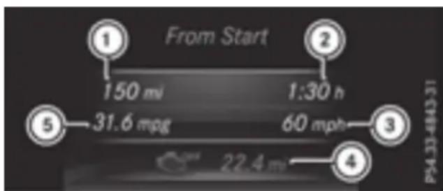
text_image
From Start 150 mi 1:30 h 31.6 mpg 60 mph 22.4 m ① ② ③ ④ PS4.33-6843-31① Distance
② Driving time
③ Average speed
④ Trip distance in electric mode
⑤ Average fuel consumption
▶ Press the ◀ or ▶ button on the steering wheel to select the Trip menu.
▶ Press the ▲ or ▼ button to select From Start or From Reset.
You can find further information in the vehicle Operator's Manual.
Service menu
Observe the notes on coolant temperature in the vehicle Operator's Manual.
▶ Press the ◀ or ▶ button on the steering wheel to select the Settings menu.
▶ Press the ▼ or ▲ button to select the Serv. submenu.
▶ Confirm by pressing OK on the steering wheel.
▶ Press the ▼ or ▲ button to select the Coolant submenu.
▶ Press OK to confirm your selection. The coolant temperature is shown in a display.
COV-
Settings menu
HYBRID submenu
Setting the maximum charge current
Using the Maximum Charge Current: function, you can limit the charge current value at which the high-voltage battery should be charged. Before starting the charging process at a power socket, check the maximum permissible charge current for the relevant power socket or the building.
Only set the maximum permissible charge current using the function if:
- it is not possible to set the charge current on the charging cable
- the precise maximum permitted charge current can only be set via the on-board computer
Before charging the high-voltage battery at a wallbox or charging station, ensure that the charging current is not limited by the function. If charging at a wallbox or a charging station, select the maximum value.
Further information on charging the high-voltage battery and setting the charge current (PLUG-IN HYBRID vehicles) page 30).
▶ Press the ◀ or ▶ button on the steering the high-voltage battery will be fully wheel to select the Settsimenu. charged.
▶ Press the ▼ or ▲ button to select the Hybrid submenu. ▶ To
▶ Confirm by pressing OK on the steering wheel.
▶ Press the ▼ or ▲ button to select Maximum Charge Current: function. You will see the selected setting.
▶ Press the OK button to save the setting. The maximum charge current values in the board computer may deviate from the charging cable values.
▶ To set a departure time: press ▼ or ▲
A, BB or C to select the desired preset.
▶ Press the OK button to confirm the selection.
▶ Press ▼ or ▲ to set the hours.
▶ Press OK to confirm.
▶ Press ▼ or ▲ to set the minutes.
▶ Press OK to confirm.
Further information on charging the high-voltage battery (PLUG-IN HYBRID vehicles) (▷ page 30).
Setting the departure time
You can climatize the vehicle interior prior to your departure with the "Set departure time" function. Further information on pre-entry climate control▶(page 18).
If you recharge the high-voltage battery, the Selecting permanent display function also displays the charging prediction The Permanent Display: function allows you
▶ Press the ◀ or ▶ button on the s wheel to select the Setgsmenu.
▶ Press the ▼ or ▲ button to select Hybrid submenu.
▶ Confirm by pressing OK on the steering wheel.
▶ Press the ▼ or ▲ button to select Departure Time: function.
You will see the selected setting.
▶ To set no departure time: press the □ button to select No Preslection
▶ Press OK to confirm.
If you recharge the high-voltage battery, multifunction display also shows the time
If you recharge the high-voltage battery, the multifunction display shows the expected condition of charge of the high-voltage battery for the departure time set.
Further information on charging the high-voltage battery (PLUG-IN HYBRID vehicles) (page 30).
Instrument cluster submenu
Selecting permanent display
nThe PermanentDDisplay: function allows you
to choose whether the multifunction display teering always shows the outside temperature or the speed.
The speed display is inverse to the speedometer.
▶ Press the ◀ or ▶ button on the steering wheel to select the Seidsimenu.
▶ Press the ▼ or ▲ button to select the Instrument Cluster submenu.
Confirm by pressing OK on the steering wheel.
▶ Press the ▼ or ▲ button to select the the Permanent Display: function.
The current setting, outside temperature Speedometer [km/h] or Speedometer [mph] appears.
▶ To change the setting: press OK again.
Display messages
| Hybrid drive system | |
| Display messages | Possible causes/consequences and ▶ Solutions |
 Vehicle OperationalSwitch the IgnitionOff Before Exiting Vehicle OperationalSwitch the IgnitionOff Before Exiting | You are exiting the vehicle when it is in a ready-to-drive state. The READY indicator in the multifunction display is on. A warning tone also sounds.If you leave the vehicle:► Safeguard the vehicle against rolling away (see the vehicle Operator's Manual).► Switch off the ignition and remove the SmartKey.If you do not leave the vehicle:► Switch off the electrical consumers, e.g. automatic climate control, seat heating.Please note the following: the electrical consumers are supplied by the 12 V battery. If the vehicle is left in a ready-to-drive state for an extended period, it will switch off once the 12 V battery is almost empty. It will then only be possible to start the vehicle using a second battery (jump-starting). |
| Change the current drive program before changing the operating mode.orExit manual drive program M before changing the operating mode | You have attempted to change the operating mode when in automatic drive program Sport, Individual (with activated Sport characteristics) or manual drive program M.► Select the Comfort, Slippery or Individual (with activated Comfort or Eco characteristics) drive program (▷ page 22).► Select the preferred operating mode HYBRID, E-MODE, E-SAVE or CHARGE (▷ page 21). |
| E-MODE Currently Unavailable | The condition of charge of the high-voltage battery has dropped to the lower limit and the E-MODE operating mode has been switched off. Driving with the internal combustion engine is activated and the operating mode switches to the basic HYBRID setting.► Continue driving using the internal combustion engine.You can switch to the E-SAVE or CHARGE operating mode as required (▷ page 21).If you select CHARGE, the high-voltage battery is charged.Once the charge level display for the high-voltage battery has increased slightly, you can switch to the E-MODE operating mode again. |
| Only E-MODE Available Power Limited Refuel Immediately | The fuel tank has been run dry and the combustion engine has been switched off.A warning tone also sounds.The vehicle will be powered by electrical energy only. Performance is restricted and the vehicle may accelerate more slowly than normal.► Refuel at the nearest gas station without fail.In the "Total range and electric range" menu, you can display the approximate range of the vehicle (▷ page 43). |
| Display messages | Possible causes/consequences and ▶ Solutions |
| Without starting engine again, consult workshop | You cannot start the engine again due to a malfunction.A warning tone also sounds.If the engine is running:► Visit a qualified specialist workshop.If you switch off the engine:► Safeguard the vehicle against rolling away (see the vehicle Operator's Manual).► Notify a qualified specialist workshop or breakdown service |
 Towing Not Permit-ted See Operator's Manual Towing Not Permit-ted See Operator's Manual | The hybrid drive system is malfunctioning.► Have the vehicle transported on a transporter or trailer to the near-est qualified specialist workshop. |
 Störung Werkstatt aufsuchen(Malfunction Visit workshop) Störung Werkstatt aufsuchen(Malfunction Visit workshop) | The hybrid drive system is malfunctioning.► Visit a qualified specialist workshop. |
 Malfunction Malfunction | The hybrid drive system is malfunctioning.► Have the vehicle towed away by a professional recovery company to the nearest qualified specialist workshop. |
 Malfunction Malfunction | The drive system is malfunctioning.The ECO start/stop function may have failed.The drive power is restricted.► Visit a qualified specialist workshop. |
 Charger Cable Con- nected Charger Cable Con- nected | The charging cable connector is connected to the vehicle socket.You cannot drive off as long as the charging cable connector is still connected.Before you drive off:► Remove the charging cable connector from the vehicle socket (▷ page 34). |
 Please Wait Depressurizing Tank Please Wait Depressurizing Tank | The fuel filler flap unlocking button has been pulled. The fuel tank must be depressurized before refueling.► Wait until the fuel tank is depressurized and the fuel filler flap is unlocked.The opening process for the fuel filler cap may take up minutes. |
 Tank is Depressur-ized Ready for Refu-eling Tank is Depressur-ized Ready for Refu-eling | The fuel tank is now depressurized. The vehicle may now be refueled.► Observe the information on refueling on the fuel filler flap.► Open the fuel filler cap and remove it (▷ page 27). |
to 15
| Display messages | Possible causes/consequences and ▶ Solutions |
 Tank VentilationMalfunction Service Required Tank VentilationMalfunction Service Required | The fuel system is malfunctioning.▶ Visit a qualified specialist workshop. |
 Acoustic Vehicle Indication Inoperative Acoustic Vehicle Indication Inoperative | The sound generator is not working. The vehicle can still be driven; however, no vehicle sounds can be generated. As a result, your vehicle may not be heard by other road users until it is very close to them, or it may not be heard at all.▶ Drive with particular care, allowing for the possibility that other road users may behave unpredictably.▶ Visit a qualified specialist workshop. |
Engine
| Display messages | Possible causes/consequences and ▶ Solutions |
 See Operator's Manual See Operator's Manual | The battery is not being charged.A warning tone also sounds.Possible causes are:a defective alternatorfaulty power electronicsa torn poly-V-belta malfunction in the electronics! Do not continue driving. The engine could otherwise overheat.▶ Pull over and stop the vehicle safely and switch off the engine, paying attention to road and traffic conditions.▶ Safeguard the vehicle against rolling away (see the vehicle Operator's Manual).▶ Consult a qualified specialist workshop. |
Vehicle
| Display messages | Possible causes/consequences and ▶ Solutions |
| Auxiliary Battery Malfunction | The auxiliary battery for the automatic transmission is no longer being charged.▸ Visit a qualified specialist workshop.▸ Until then, set the automatic transmission to position P before you switch off the engine.▸ Before leaving the vehicle, apply the electric parking brake. |
 Pre-Entry Climate Ctrl. (Via Smart-Key) Available Again After Engine Start Pre-Entry Climate Ctrl. (Via Smart-Key) Available Again After Engine Start | With the engine switched off, you have attempted to switch on the entry climate control more than twice.▸ Let the engine run for ten seconds.After running the engine, the pre-entry climate control is operational again. |
 Pre-Entry Climate Ctrl. (Via Smart-Key) Inoperative HV Battery Low Pre-Entry Climate Ctrl. (Via Smart-Key) Inoperative HV Battery Low | The on-board voltage is too low. The pre-entry climate control cannot be switched on.▸ Drive for a longer distance.The battery is being charged. When the condition of charge of the high-voltage battery is over the specified minimum, pre-entry climate control is operational again. |
Warning and indicator lamps in the instrument cluster
Safety systems
The information "while the engine is running" given in the vehicle Operator's Manual regarding signaling behavior of a warning/indicator lamp corresponds to the READY driving status. When warning/indicator lamp lights up in the READY driving status with the corresponding information, the causes/consequences and solutions given in the vehicle Operator's Manual also apply to a vehicle.
Warning/indicator lamp
▷ Signal type
Possible causes/consequences and Solutions

BRAKE
▶ BRAKE (USA only), (1) (Canada only): the red brake system warning lamp is shown in the READY driving status.
A warning tone also sounds.

WARNING
RBS is malfunctioning. Pedal travel may be longer than usual and braking performance may be affected.
There is a risk of an accident.
▶ Pull over and stop the vehicle safely as soon as possible, paying attention and traffic conditions. Do not continue driving under any circumstances.
▶ Safeguard the vehicle against rolling away (see the vehicle Operator's Manu
▶ Consult a qualified specialist workshop.
▶ Observe the additional display messages in the multifunction display.
RBS
The yellow RBS (Recuperative Brake System) warning lamp is on in driving condition READY.
A warning tone also sounds.

WARNING
RBS is malfunctioning. Pedal travel may be longer than usual and braking performance may be affected.
There is a risk of an accident.
▶ If the multifunction display shows a display message, please observe this.
▶ Drive on carefully.
▶ Visit a qualified specialist workshop immediately.
Important safety notes
Observe the amended notes on operating safety of the multimedia system in the vehicle's Operator's Manual

WARNING
If you operate information systems and co- munication equipment integrated in the vehi- cle while driving, you will be distracted fro traffic conditions. You could also lose cont of the vehicle. There is a risk of an accident.
Only operate the equipment when the traffic situation permits. If you are not sure that is possible, park the vehicle paying attention to traffic conditions and operate the equipment when the vehicle is stationary.
You must observe the legal requirements for the country in which you are currently driving operating the multimedia system.
Information on operating the multimedia can be found in the vehicle's Operator's
Vehicle menu
Menu overview
The vehicle menu of the multimedia system is added to or changed for the hybrid operation the following displays:
• Energy flow display (▷ page 50)
- Fuel consumption display and the generated. electrical energy (page 50)
Open the vehicle menu with the 📄 button on the multimedia system.
Further possibilities for calling up the menu can be found in the vehicle's Operator's Manual.
The current energy flow in the hybrid drive system can also be displayed in the multifunction display ( page 40).
Displaying fuel consumption and generated electricity
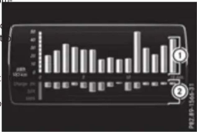
bar
| Category | DRR (MCI Units) | |---|---| | 1 | 50 | | 2 | 20 | | 3 | 30 | | 4 | 35 | | 5 | 30 | | 6 | 25 | | 7 | 25 | | 8 | 15 | | 9 | 15 | | 10 | 15 | | 11 | 15 | | 12 | 50 | | 13 | 30 | | 14 | 20 | | 15 | 30 | | 16 | 40 | | 17 | 40 | P82.8P-13Mo-31① Fuel consumption
② Electrical energy generated
Every bar of the graph displays the average item value for one minute.
Fuel consumption indicator ① may differ from the indicator in the From Start trip computer in the Trip menu.
To reset values: the values are reset along with the From Start trip computer (▷ page 43).
▶ To select Consumption: turn and press the controller.
The display of the multimedia system shows fuel consumption ① and electrical energy generated ② for the past 15 minutes of driv-
Energy flow display
▶ Press the 📄 button on the multimedia system.
The vehicle menu is displayed.
▶ To select Energy Flow: turn and press the controller.
The energy flow is displayed.
▶ To exit the display: press the ← button on the controller.
Engine compartment
Checking coolant level
Observe the notes on checking and adding coolant in the vehicle Operator's Manual.
The second coolant expansion tank in your vehicle's engine compartment must not be filled.
Battery (vehicle)
Important safety notes
Your vehicle is equipped with a 12 V batt a high-voltage battery.
For the 12 V battery, observe the notes "Battery (vehicle)" in the vehicle Operator's Manual.

DANGER
The vehicle's high-voltage electrical system under high voltage. If you modify component in the vehicle's high-voltage electrical system
or touch damaged components, you may be consult an authorized Mercedes-Benz Center if electrocuted. The components in the vehi- you wish to leave your vehicle parked for a long cle's high-voltage electrical system may be period of time.
damaged in an accident, although the damage is not visible. There is a risk of fatal injury.
Following an accident, do not touch any high-voltage components and never modify the vehicle's high-voltage electrical system. Have
the vehicle towed away after an accident the vehicle's high-voltage electrical system checked by a qualified specialist workshop.

WARNING
In the event of a vehicle fire, the internal sure of the high-voltage battery can exceed
critical value. In this case flammable gas escapes through a ventilation valve on the underbody. The gas can ignite. There is a of injury.
Leave the danger zone immediately. Secure the danger area at a suitable distance, who observing legal requirements.

WARNING
If the housing of the high-voltage battery been damaged, electrolyte and gases may leak out. These are poisonous and caustic. There is a risk of injury.
Avoid contact with skin, eyes or clothing. Immediately rinse electrolyte splashes off with water and seek medical attention straight away.
the high-voltage battery. If the vehicle is idle for lengthy periods leave the high-voltage battery connected to a charging station.
If the battery charge is sufficient, the high-voltage battery can also supply the 12 V battery with energy. This happens only if the battery charge of the 12 V battery requires this, e.g. after using electrical consumers for an extended period with the engine switched off. As the on-board voltage is continuously monitored this can also be performed when the engine is switched off. The battery charge of the 12 V battery and the on-board voltage are thereby kept stable for longer.
beConsult an authorized Mercedes-Benz Center if you wish to leave your vehicle parked for a long period of time.
Charging the high-voltage battery while the vehicle is stationary

WARNING
and Combustion engines emit poisonous exhaust gases such as carbon monoxide. Inhaling these exhaust gases leads to poisoning. There is a risk of fatal injury. Therefore never leave the engine running in enclosed spaces without sufficient ventilation.
! Only charge the high-voltage battery in the "Charging when stationary" mode. Do not connect any battery chargers to the high-voltage battery. This could damage the vehicle's high-voltage electrical system.
▶ Bring the vehicle to a stop with the engine wilst running.
The engine powers the electric motor. The electric motor operates as a generator. The high-voltage battery is being charged.
The high-voltage battery has been discharged excessively, charge the high-voltage battery to at least 60%. In "Charging while stationary" mode, you can monitor the condition of charge of the high-voltage battery up to a maximum of 70% in the COMAND display and the multifunction display▶(page 40).
! Exhaustive discharge caused by the vehicle standing idle for lengthy periods can damage
Jump-starting
Observe the notes on jump-starting in the vehicle Operator's Manual.
If your vehicle has been jump-started, the electric drive may not be available for approximately 30 minutes.
Jump-starting is not considered to be a normal operating condition.
Jumper cables and further information regarding jump-starting can be obtained at any qualified specialist workshop.
Towing
Important safety notes
Observe the notes on towing away and transporting in the vehicle Operator's Manual.
Towing the vehicle with the rear axle raised or transporting the vehicle should be carried out only by professional recovery companies. It is better to have the vehicle transported than to have it towed away.
In the following cases, the vehicle must not be towed but be transported instead:
• The multifunction display is not working.
- The Towing Not Permitted See Operator's Manual message is shown in the multifunction display.
If the vehicle is in a dangerous area, it can be towed out of that area with both axles on the ground. In this case, the towing distance must not be greater than 165 ft (50 m) and must not exceed a towing speed of 6 mph (10 km/h). For longer distances, have the vehicle loaded and transported.
Filling capacities
Observe the notes on service products in the vehicle Operator's Manual.
| Capacity | |
| Fuel tank content 21.1 | US gal(80.0 l) |
| Fuel, of which reserve | fuel Approx.3.2 US gal(12.0 l) |
| Engine oil capacityincluding oil filter | 7.4 US qt (7.0 l) |
| Coolant | Approx.10.3 US qt (9.7 |
| Refrigerant | 37.0 ± 0.4 oz(1050 ± 10 g) |
| PAG oil | 3.9 ± 0.4 oz(110 ± 10 g) |
Vehicle data
General notes
Please note that for the specified vehicle data:
• the heights specified may vary as a result of:
- Tires
- Load
- Condition of the suspension
- Optional equipment
- optional equipment reduces the maximum payload.
Observe the information relating to level co (see the vehicle Operator's Manual).
Dimensions and weights
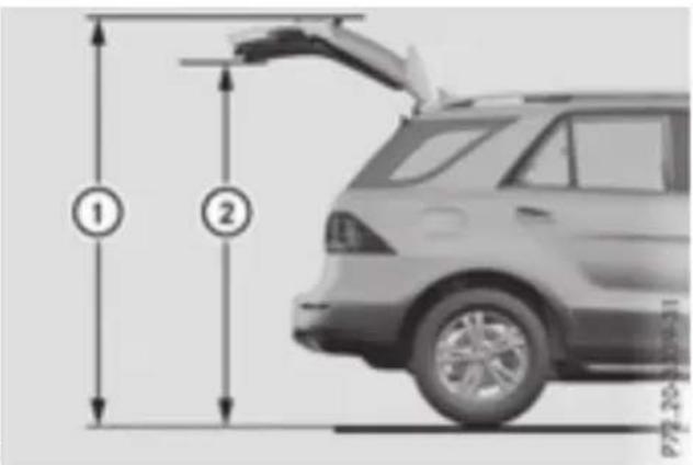
text_image
① ② 115000-2074| GLE 550 e4MATIC(1) | 1Opening height | 2Max.headroom |
| Steel suspension | 86.4 in2195 mm | 78.2 in1987 mm |
| AIRMATIC package | 84.3 in -87.2 in2140 mm-2215 mm | 76.0 in -79.0 in1931 mm-2006 mm |
| ON&OFFROAD packagedata: | 84.3 in -88.4 in2140 mm-2245 mm | 76.0 in -80.2 in1931 mm-2036 mm |
Missing values were not available at time of going to print.
| GLE 550 e 4MATIC | |
| Vehicle length | 189.7 in(4819 mm) |
| ntrol Vehicle width including exterior mirrors | 84.3 in(2141 mm) |
| Maximum vehicle height (steel suspension) | 70.7 in(1796 mm) |
| Maximum vehicle height (AIRMATIC package) | 71.6 in(1818 mm) |
| Maximum vehicle height (ON&OFFROAD package) | 72.8 in(1848 mm) |
| Minimum vehicle height | 69.2 in(1758 mm) |
| Wheelbase | 114.8 in(2915 mm) |
| Maximum ground clearance (steel suspension) | 8.0 in(202 mm) |
| Maximum ground clearance (AIRMATIC package) | 10.0 in(255 mm) |
| Maximum ground clearance (ON&OFFROAD package) | 11.2 in(285 mm) |
| Minimum ground clearance | 7.1 in(180 mm) |
| Turning radius | 38.7 ft(11.80 m) |
| Maximum roof load | 220 lb(100 kg) |
| Permissible trailer load,braked at a minimum gradi- (2000 kg)ent-climbing capability of 12%from a standstill | 4410 lbs |
| Maximum drawbar nose-weight, the drawbar nose-weight is not included in the trailer load | 355 lbs(160 kg) |
| Gross rear axle weight rat- ing when towing a trailer | 3704 lbs(1680 kg) |
Mounting dimensions
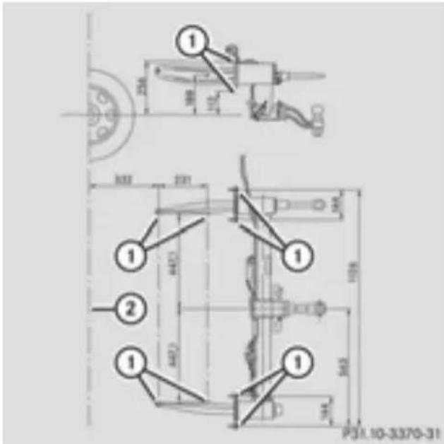
text_image
Technical drawing with dimension annotations and numbered components, likely from an engineering or mechanical drawing.① Anchorage points for the trailer tow hit
② Rear axle center line
Ball position of the ball coupling
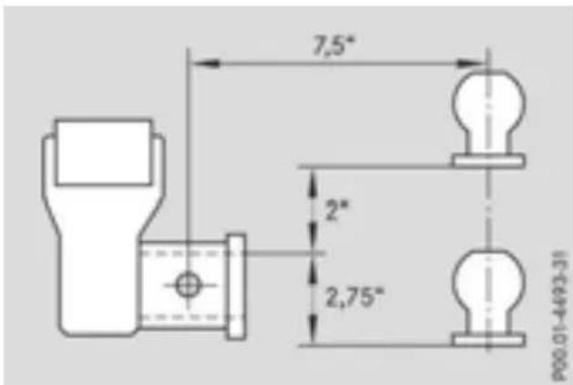
text_image
7,5" 2" 2,75" P00.01-4493-31When choosing a ball coupling, the dimensions stated in the illustration must not be exceeded.
! If you have a trailer tow hitch retrofitted, changes to the cooling system and drive train may be necessary, depending on the vehicle type.
If you have a trailer tow hitch retrofitted, Missing values were not available at time of observe the anchorage points on the chassing to print. frame.
High-voltage battery
| GLE 500 e 4MATIC | |
| Model | |
| Energy content | |
| Nominal capacity | |
| Range in electric-only mode (according to NEDC) | |
| Charging time at16 A(using a charging station or wallbox) | |
| Charging time at8 A(using a mains socket) | |