
KHG 602 - Cooker KENWOOD - Free user manual and instructions
Find the device manual for free KHG 602 KENWOOD in PDF.

| Product Type | Built-in gas hob (cooktop) |
| Model | Kenwood KHG 602 |
| Dimensions (approx.) | 580 mm (W) x 510 mm (D) x 55 mm (H) |
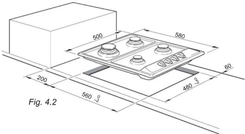
| Cut-out Dimensions | 560 mm x 480 mm |
| Weight (approx.) | 12 kg |
| Power Supply | 230 V ~ 50 Hz; 3 A fuse (BS1362) |
| Gas Types | Natural Gas G20 (20 mbar) / LPG G30/G31 (28-30/37 mbar) |
| Total Gas Input (max) | 11.25 kW (all burners on max) |
| Burners | 1 x Triple ring (3.50 kW), 1 x Rapid (3.00 kW), 2 x Semirapid (1.75 kW each), 1 x Auxiliary (1.00 kW) |
| Ignition | Electric ignition integrated in knobs (mains powered) |
| Safety Features | Flame failure safety valve on all burners; auto shut-off if flame extinguished |
| Pan Supports | Enamelled steel pan stands; wok stand included for triple ring burner |
| Control Knobs | 5 knobs with gas flow regulation (closed, max, min) |
| Installation Requirements | Built-in; min 650 mm clearance above; min 200 mm from side walls; ventilation per BS 5440-2; thermal barrier if above drawer/oven |
| Gas Connection | 1/2" BSPP male or female; flexible hose per BS669; inlet union adjustable |
| Cleaning | Do not use steam cleaner; clean with damp soapy cloth; avoid acidic/alkaline substances; burner parts removable |
| Maintenance | Replace injectors for gas conversion; adjust minimum flame via screw; lubrication by qualified technician only |
| Guarantee | 12 months parts and labour (UK & Channel Islands) |
| CE Compliance | Directives 2009/142/EC (Gas), 2006/95/EC (Low Voltage), 2004/108/EC (EMC), 93/68/EEC, 2011/65/EU |
| Accessories Included | Wok stand, installation brackets, sealing material, gas injectors (for conversion may be separate) |
Frequently Asked Questions - KHG 602 KENWOOD
User questions about KHG 602 KENWOOD
0 question about this device. Answer the ones you know or ask your own.
Ask a new question about this device
Download the instructions for your Cooker in PDF format for free! Find your manual KHG 602 - KENWOOD and take your electronic device back in hand. On this page are published all the documents necessary for the use of your device. KHG 602 by KENWOOD.
USER MANUAL KHG 602 KENWOOD
Instructions for use - Installation advice
natural_image
Four identical electric cooktops with black circular burners and a control panel (no text or symbols visible)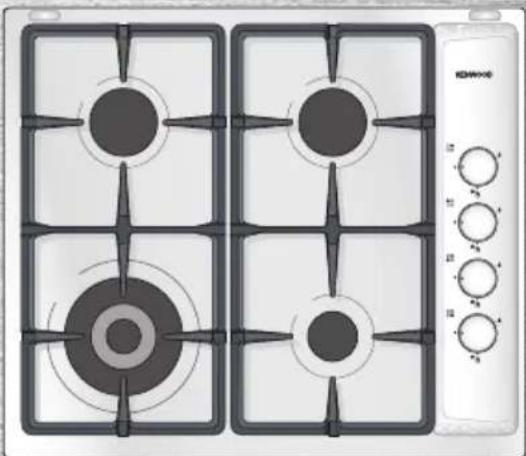
natural_image
Four identical electric cooktops with black circular tops and control knobs, arranged in a 2x2 grid (no visible text or symbols)
KENWOOD
Before operating this hob, please read these instructions carefully
CONTENTS Page Number
Introduction 3
Important Safety Precautions & Recommendations 4 - 5
Features 6
How to Use the Cooktop 7
Cleaning & Maintenance 10 - 12
Advice for the Installer 13
Installation 14 - 16
Gas Installation 17 - 21
Electrical Installation 22 - 23
Guarantee & After Sales Service 24
Dear Customer,
Thank you for purchasing the Kenwood KHG 601, KHG 602 built-in cooking hobs.
The safety precautions and recommendations listed below are for your own safety and that of others. They will also provide a means by which to make full use of the features offered by your appliance.
Please retain this booklet for future reference.
This appliance must be used only for the task it has explicitly been designed for, that is for cooking foodstuffs. Any other form of usage is to be considered as inappropriate and therefore potentially dangerous.
The manufacturer declines all responsibility in the event of damage caused by improper, incorrect or illogical use of the appliance.
DECLARATION OF CE CONFORMITY
This cooking hob has been designed, constructed, and marketed in compliance with:
- Safety requirements of EU Directive "Gas" 2009/142/EC;
- Safety requirements of EU Directive "Low Voltage" 2006/95/EC;
• Protection requirements of EU Directive "EMC" 2004/108/EC; - Requirements of EU Directive 93/68/EEC;
- Requirements of EU Directive 2011/65/EU.
IMPORTANT SAFETY PRECAUTIONS AND RECOMMENDATIONS
IMPORTANT: This appliance is designed and manufactured solely for the cooking of domestic (household) food and is not suitable for any non domestic application and therefore should not be used in a commercial environment.
The appliance guarantee will be void if the appliance is used within a non domestic environment i.e. a semi commercial, commercial or communal environment.
Read the instructions carefully before installing and using the appliance.
• These instructions are only valid for the countries indicated by the symbols on the cover of the instruction booklet and on the appliance itself.
- After having unpacked the appliance, check to ensure that it is not damaged.
In case of doubt, do not use it and consult your supplier or a professionally qualified technician.
- Packing elements (i.e. plastic bags, polystyrene foam, nails, packing straps, etc.) should not be left around within easy reach of children, as these may cause serious injuries.
- Some appliances are supplied with a protective film on aluminium parts. This film must be removed before using appliance.
- IMPORTANT: The use of suitable protective clothing/gloves is recommended when handling or cleaning this appliance.
- Do not attempt to modify the technical characteristics of the appliance as this may become dangerous to use. The manufacturer declines all responsibility for any inconvenience resulting from the inobservance of this condition.
- CAUTION: this appliance must only be installed in a permanently ventilated room in compliance with the applicable regulations.
- Do not carry out cleaning or maintenance operations on the appliance without having previously disconnected it from the electric power supply.
- Do not use a steam cleaner because the moisture can get into the appliance thus make it unsafe.
-
Do not touch the appliance with wet or damp hands (or feet).
-
Do not use the appliance whilst in barefoot.
- If you should decide not to use this appliance any longer (or decide to substitute another model), before disposing of it, it is recommended that it be made inoperative in an appropriate manner in accordance to health and environmental protection regulations, ensuring in particular that all potentially hazardous parts be made harmless, especially in relation to children who could play with unused appliances.
- The various components of the appliance are recyclable. Dispose of them in accordance with the regulations in force in your country. If the appliance is to be scrapped, remove the power cord.
• After use, ensure that the knobs are in the off position. - Children less than 8 years of age shall be kept away unless continuously supervised.
- This appliance can be used by children aged from 8 years and above and persons with reduced physical, sensory or mental capabilities or lack of experience and knowledge if they have been given supervision or instruction concerning use of the appliance in a safe way and understand the hazards involved. Children shall not play with the appliance. Cleaning and user maintenance shall not be made by children without supervision.
- The manufacturer declines all liability for injury to persons or damage to property caused by incorrect or improper use of the appliance.
- WARNING: During use the appliance and its accessible parts become hot; they remain hot for some time after use.
- Care should be taken to avoid touching heating elements on the hob.
- To avoid burns and scalds, young children should be kept away.
- Make sure that electrical cables connecting other appliances in the proximity of the cooktop cannot come into contact with the hob.
- WARNING: Unattended cooking on a hob with fat or oil can be dangerous and may result in fire. NEVER try to extinguish a fire with water, but switch off the appliance and then cover flame e.g. with a lid or a fire blanket.
- WARNING: Danger of fire: do not store items on the cooking surfaces.
- WARNING: When correctly installed, your product meets all safety requirements laid down for this type of product category. However special care should be taken around the underneath of the appliance as this area is not designed or intended to be touched and may contain sharp or rough edges, that may cause injury.
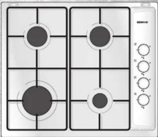
1 - FEATURES
Mod: KHG 601
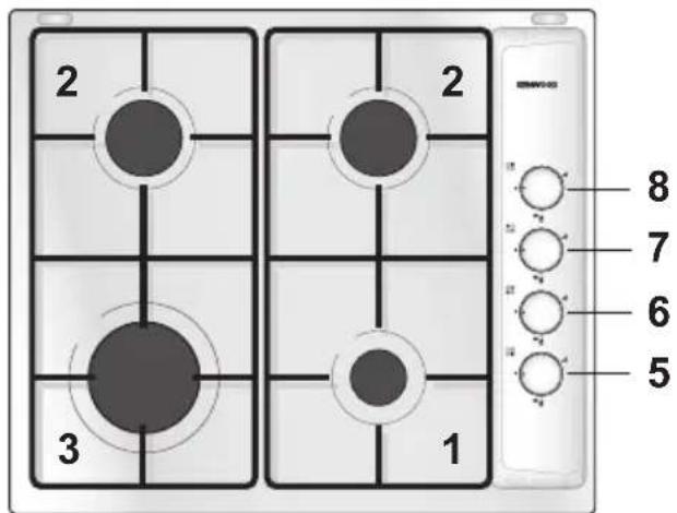
Fig. 1.2 Fig. 1.1
Mod: KHG 602
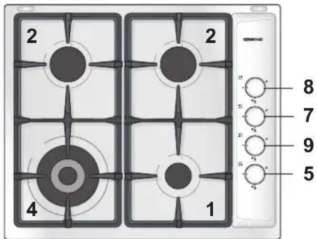
This appliance is Class 3 This appliance is Class 3
GAS BURNERS
- Auxiliary burner (A) 1,00 kW
- Semirapid burner (SR) 1,75 kW
- Rapid burner (R) 3,00 kW
- Triple ring burner (TC) 3,50 kW
CONTROL PANEL DESCRIPTION
- Auxiliary burner control knob (1)
- Rapid burner control knob (3)
- Left semirapid burner control knob (2)
- Right semirapid burner control knob (2)
- Triple ring burner control knob (4)
NOTE:
• The electric ignition is incorporated in the knobs.
- The model has a safety valve system fitted, the flow of gas will be stopped if and when the flame should accidentally go out.
CAUTION:
If the burner is accidentally extinguished, turn the gas off at the control knob and wait at least 1 minute before attempting to relight.
CAUTION:
Gas hobs produce heat and humidity in the environment in which they are installed.
Ensure that the cooking area is well ventilated by opening the natural ventilation grilles or by installing an extractor hood connected to an outlet duct.
CAUTION:
If the hob is used for a prolonged time it may be necessary to provide further ventilation by opening a window or by increasing the suction power of the extractor hood (if fitted).
2 - HOW TO USE THE COOKTOP
GAS BURNERS
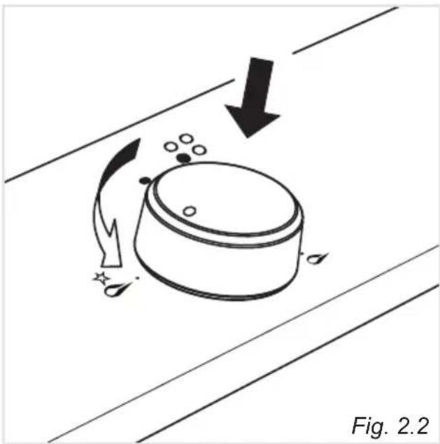
Gas flow to the burners is adjusted by turning the knobs (illustrated in figs. which control the valves.
Turning the knob so that the indicator points to the symbols printed on the panel achieves the following functions:
- full circle

closed valve
- symbol

maximum
aperture or flow
- symbol

minimum
aperture or flow
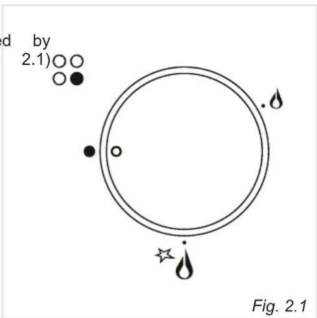
- To reduce the gas flow to minimum, rotate the knob further anti-clockwise to point the indicator towards the small flame symbol.
- The maximum aperture position permits rapid boiling of liquids, whereas the minimum aperture position allows slower warming of food or maintaining boiling conditions of liquids.
- Other intermediate operating adjustments can be achieved by positioning the indicator between the maximum and minimum aperture positions, and never between the maximum aperture and closed positions.
natural_image
Diagram showing a cooking pot with arrows indicating rotation and motion, labeled Fig. 2.2 (no text or symbols on the diagram itself)Caution!
The cooking hob becomes very hot during operation.
Keep children well out of reach.
N.B. When the cooktop is not being used, set the gas knobs to their closed positions and also close the cock valve on the gas bottle or the main gas supply line.
LIGHTING GAS BURNERS FITTED WITH SAFETY VALVE DEVICE
In order to light the burner, you must:
- Turn the knob in an anti-clockwise direction up to the maximum aperture, push in and hold the knob; this will light the gas.
If there is no mains electrical supply, bring a lighted match close to the burner. - Wait about ten seconds after the gaslights before releasing the knob (starting time for the valve).
- Adjust the gas valve to the desired position.
If the burner flame should go out for some reason, the safety valve will automatically stop the gas flow.
To re-light the burner, return the knob to the closed “●” position, wait for at least 1 minute and then repeat the lighting procedure.
N.B.: If your local gas supply makes it difficult to light the burner with the knob set to maximum, set the knob to minimum and repeat the operation.
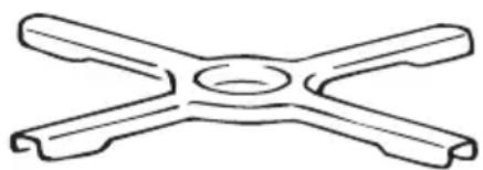
AUXILIARY GRATE FOR SMALL PANS - Only for the model KHG 601 (fig. 2.3)
This grate is to be placed on top of the (smaller) auxiliary burner when using small diameter pans, in order to prevent them from tipping over.
natural_image
Simple line drawing of a four-way pipe fitting with a central circular hole (no text or symbols)Fig. 2.3
CHOICE OF BURNER
The symbols printed on the panel beside the gas knobs indicate the correspondence between the knob and the burner.
The most suitable burner is to be chosen according to the diameter and volume capacity of the container to be warmed.
It is important that the diameter of the pots or pans suitably match the heating potential of the burners in order not to jeopardise the efficiency of the burners, bringing a waste of gas fuel. A small diameter pot or pan placed on a large burner does not necessarily mean that boiling conditions are reached quicker.
DIAMETERS OF PANS WHICH MAY BE USED ON THE HOBS
| BURNERS MINIMUM | MAX. | |
| Auxiliary (1) 12 cm | 14 cm | |
| Semirapid 16 cm | 24 cm | |
| Rapid | 24 cm | 26 cm |
| Triple-ring 26 cm | 28 cm | |
| Wok (2) Max 36 cm | ||
| do not use pans with concave or convex bases | ||
(1) with grill for small cookware: minimum diameter 6 cm (only for model KHG 601)
(2) only for model KHG 602
natural_image
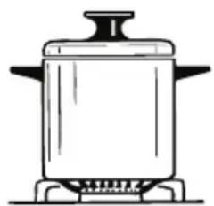
Line drawing of a cooking pot on a stove (no text or symbols)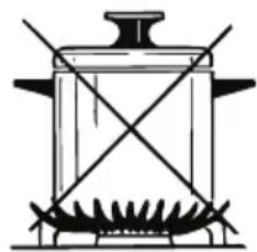
natural_image
Simple line drawing of a cooking pot with stirrer and crossed panes (no text or symbols)Fig. 2.4
CORRECT USE OF THE TRIPLE-RING BURNER
Only flat bottom pans of the correct size are to be placed on the pan support above the Triple-ring burner.
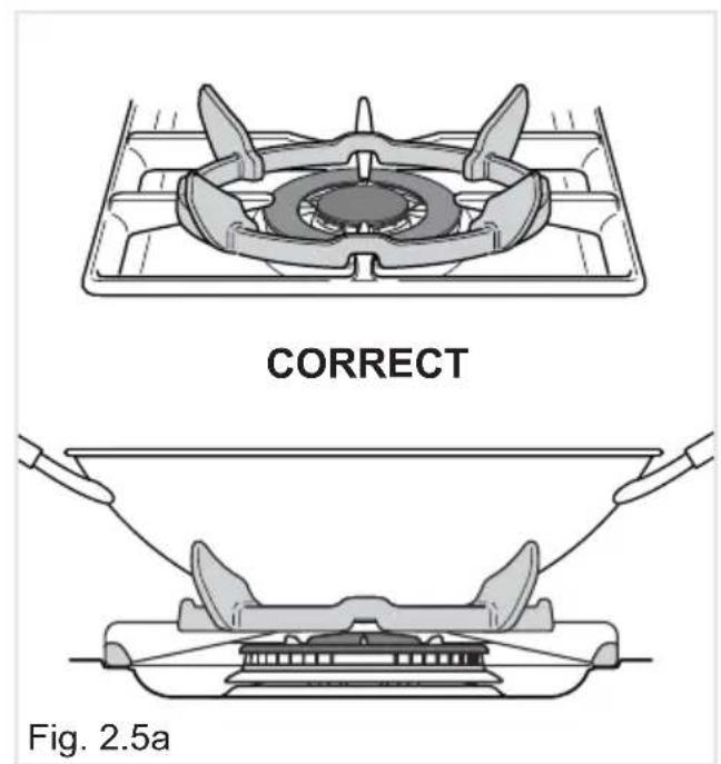
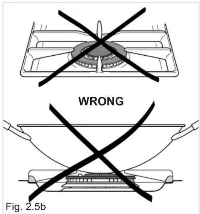
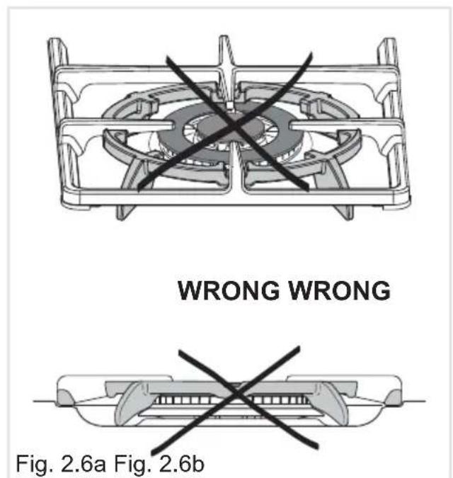
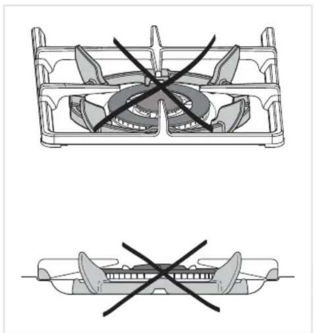
When using a WOK, the supplied wok stand must be placed onto the pan stand to avoid any faulty operation of the triple-ring burner (fig. 2.5a). The wok should not be placed directly onto the pan support without the use of the supplied wok stand (fig. 2.5b).
IMPORTANT:
When using the wok stand it MUST ONLY BE PLACED over the pan support for the triple-ring burner (fig.2.5a). Under no circumstances should the wok stand be placed under the pan supports (figs 2.6a - 2.6b). Incorrect placement of the wok stand in this manner may impinge the flame resulting in incomplete combustion and give rise to harmful levels of Carbon Monoxide (CO).
natural_image
Technical line drawing of a fan or vent assembly with crosshair marks, no text or symbols present3 - CLEANING AND MAINTENANCE
GENERAL ADVICE
• Before you begin cleaning, you must ensure that the appliance is switched off at the cooker switch.
- The periodical lubrication of the gas taps must be done only by specialized personnel.
- If a tap becomes stiff, do not force; contact your local After Sales Service Centre.
- It is advisable to clean when the appliance is cold and especially when cleaning the enamelled parts.
- Avoid leaving alkaline or acidic substances (lemon juice, vinegar, etc.) on the surfaces.
- Avoid using cleaning products with a chlorine or acidic base.
- Important: The use of suitable protective clothing/gloves is recommended when handling or cleaning this appliance.
• Under no circumstances should any external covers be removed for servicing or maintenance except by suitable qualified personnel.
WARNING:
When correctly installed, your product meets all safety requirements laid down for this type of product category.
However special care should be taken around the rear or the underneath of the appliance as these areas are not designed or intended to be touched and may contain sharp or rough edges, that may cause injury.
CLEANING
- Stainless steel hob: Spillage on the hob can usually be removed by a damp soapy cloth. More obstinate stains can be removed by using a proprietary stainless steel cleaning product that does not contain chlorine or acidic base.
- Control panel: Clean very carefully with water and neutral soap; the cloth used must be rinsed well and must be free of any cleaning chemicals to avoid damaging any screen print on the facia.
- Painted surfaces: Clean very carefully with water and neutral soap; the cloth used must be rinsed well and must be free of any cleaning chemicals.
- Pan stands & burner caps: Clean with a sponge and soapy water or proprietary cream cleaner. Alway dry thoroughly. DO NOT PUT IN THE DISHWASHER.
- Burner bodies (aluminium alloy): They should be cleaned with soapy water and a clean cloth. For stubborn stains a proprietary cream or stainless steel cleaner may be used; however to maintain a uniform finish we would recommend the whole area is cleaned. NOTE: Please ensure the slots/castlellations are kept free of the any material/cleaner.
- Gaskets fitted below control knobs: Check they are well fitted and correctly in place.
Attention!
The appliance gets very hot, mainly around the cooking areas. It is very important that children are not left alone in the kitchen when you are cooking.
Do not use a steam cleaner because the moisture can get into the appliance thus make it unsafe.
BURNERS AND GRIDS
• These parts can be removed and cleaned with appropriate products.
• After cleaning, the burners and their flame spreaders must be well and correctly replaced.
- It is very important to check that the burner flame spreader and the have been correctly positioned.
- Failure to do so can cause serious problems.
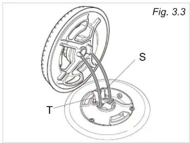
- Check that the electrode "S" (figs. 3.1 - 3.3) is always clean to ensure trouble-free sparking.
- Check that the probe "T" (figs. 3.1 - 3.3) next to each burner is always clean to ensure the correct operation of the safety valves.
Both the probe and ignition plug must be very carefully cleaned.
Note: To avoid damage to the electric ignition do not use it when the burners are not in place.
GLASS LID (Optional)
dried
cap
natural_image
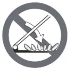
Prohibition sign depicting a crossed lever over soil with leaves, no text or symbols presentDo not shut lid when burner alight. ATTENTION
√ Do not lower the glass lid when the gas burners are still hot or when the oven is working or still hot.
√ Do not lay on the glass lid hot pans and heavy kitchen utensils.
√ Dry off any liquid which may have spilt on the cover before opening it.
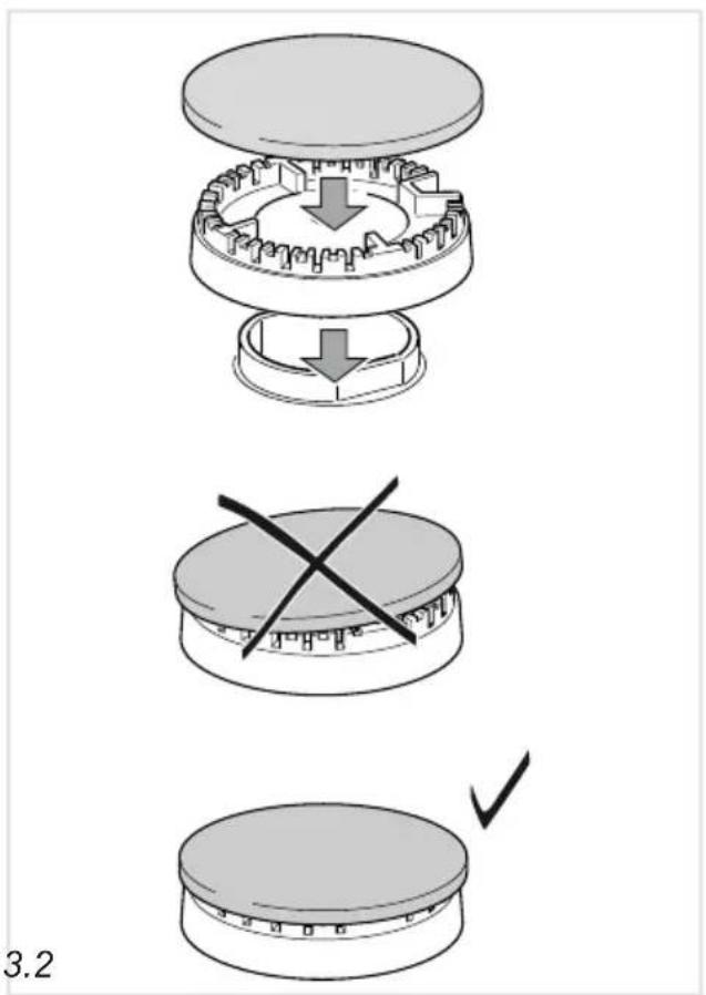
CORRECT REPLACEMENT OF THE AUXILIARY, SEMIRAPID AND RAPID BURNERS
It is very important to check that the burner flame spreader "F" and the cap "C" have been correctly positioned (see figs. 3.1 and 3.2).
Failure to do so can cause serious problems.
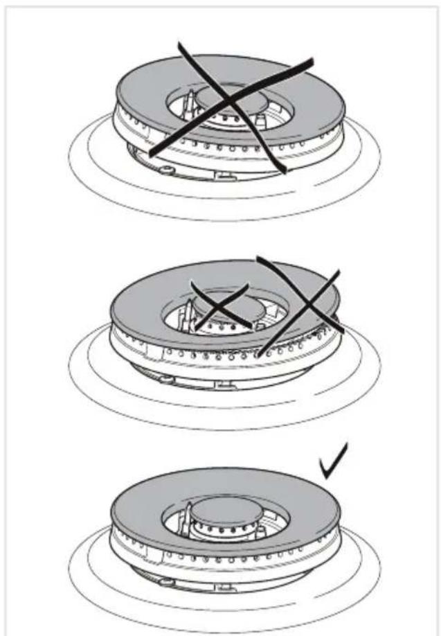
CORRECT POSITION OF THE TRIPLE RING BURNER
The triple ring burner must be correctly positioned as indicated by the arrows in fig. 3.3.
The burner correctly positioned must not rotate (fig. 3.4).
Then position the cap “A” and the ring “B” (figs. 3.4 - 3.5).
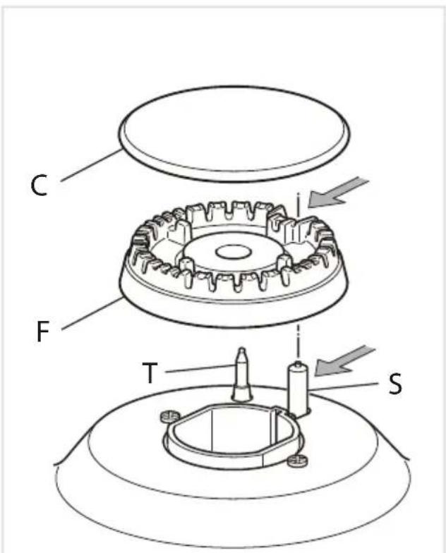
Fig. 3.1 Fig. 3.2
natural_image
Three-step diagram showing a mechanical component with cross marks, no text or symbols present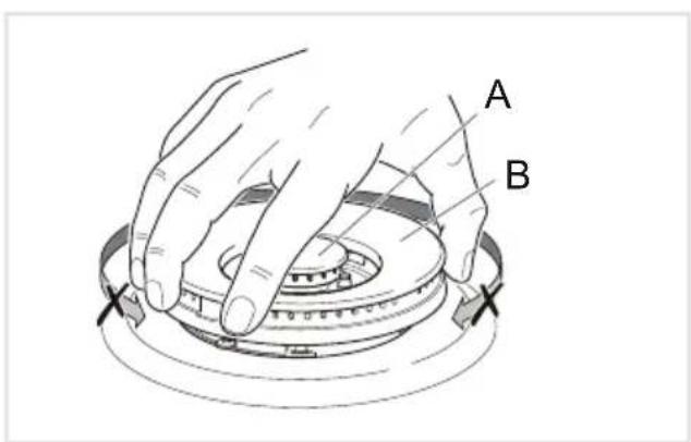
Fig. 3.5 Fig. 3.4
Advice for the installer
IMPORTANT
- The appliance is designed and approved for domestic use only and should not be installed in a commercial, semi commercial or communal environment.
Your product will not be guaranteed if installed in any of the above environments and could affect any third party or public liability insurances you may have.
The appliance may be installed in a kitchen, kitchen/diner or a bed sitting room, but not in a room or space containing a bath or a shower without first consulting current regulations.
The appliance must not be installed in a bed-sitting room of less than 20 m ^4 .
- Hob installation must only be carried out by a SUITABLY QUALIFIED AND REGISTERED TECHNICIAN and in compliance with local safety standards. Failure to observe this rule will invalidate the warranty.
- The appliance must be installed in compliance with regulations in force in your country and in observation of the manufacturer's instructions.
• Always disconnect the appliance from the power supply before carrying out any maintenance operations or repairs.
- Some appliances are supplied with a protective film on steel and aluminium parts. This film must be removed before using the hob.
• The appliance must be housed in heat-resistant units.
- These tops are designed to be embedded into kitchen fixtures measuring 600 mm in depth.
- The walls of the units must not be higher than work top and must be capable of resisting temperatures of 105 °C above room temperature.
- Do not install the appliance near inflammable materials (eg. curtains).
- Important: The use of suitable protective clothing/gloves is recommended when handling or installing this appliance.
WARNING
When correctly installed, your product meets all safety requirements laid down for this type of product category.
However special care should be taken around the underneath of the appliance as this area is not designed or intended to be touched and may contain sharp or rough edges, that may cause injury.
4 - INSTALLATION
TECHNICAL INFORMATION FOR THE INSTALLER
In order to install the cooker top into the kitchen fixture, a hole with the shown in fig. 4.2 has to be made, bearing in mind the following:
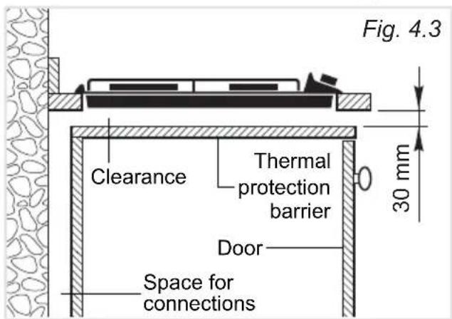
- If the cooktop is not installed directly above an oven and/or if its base is accessible through a cupboard or drawer space after installation, a thermal protection barrier must be installed below the base of the cooktop as indicated in fig.4.3.
The thermal protection barrier must be:
- removable with the use of a tool for installation and service;
- heat-resistant;
– made from low thermal conductivity material.
• A 30 mm ventilation gap must be
provided between the bottom of the appliance and any cabinetry, draw unit, thermal protection barrier or appliance.
• If the cooktop is installed above an oven, the oven shall have a cooling fan motor; the two appliances shall be connected to the gas and/or electrical supply with independent connections.
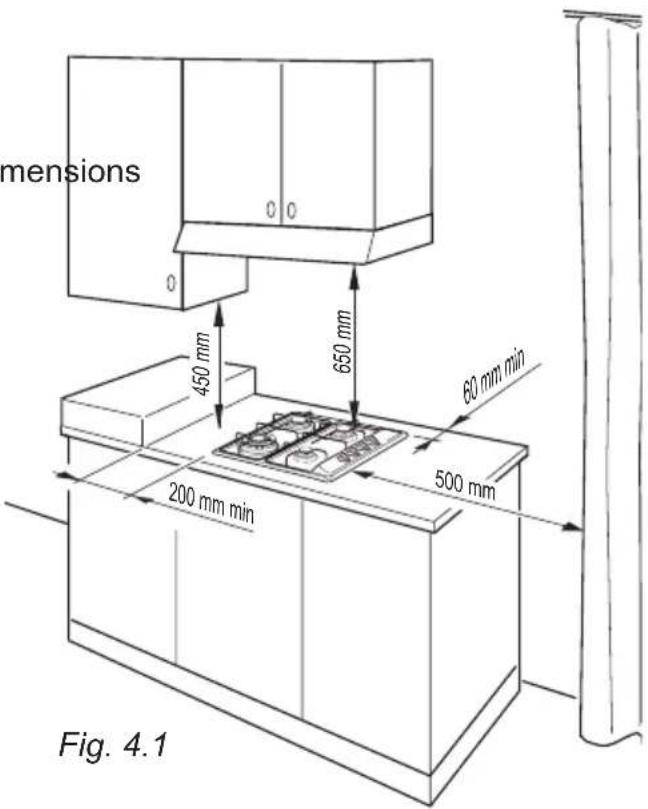
• The hob must be kept no less than 200 mm away from any side wall (fig. 4.2).
• The hob must be installed at least 60 mm from the wall (fig. 4.2).
- There must be a distance of at least 650 mm between the hob and any wall cupboard or extractor hood positioned immediately above (see fig. 4.1).
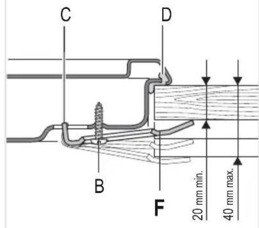
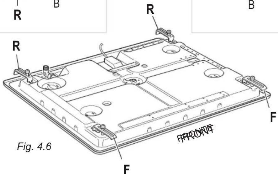
FASTENING THE INSTALLATION BRACKETS (figs. 4.4, 4.5, 4.6)
• Each cooker top is provided with an installation kit including brackets and screws for fastening the top to fixture panels from 2 to 4 cm thick.
- Turn the cooker top upside down and fasten the brackets "F and R" to the appropriate socket holes, without tightening the screws "B" for the moment.
• Make sure that the brackets are fastened as shown in the figures.
FASTENING THE COOKER TOP (figs. 4.4, 4.5, 4.6)
- Spread the sealing material "D" out along the fixture hole, making sure that the junctions overlap at the corners.
- Insert the cooker top into the hole and position it correctly.
- Adjust the position of the brackets "F and R"; tooth C of the tabs should go into the hole. Tighten screws "B" to block the cooker top firmly in position.
- With a sharp cutter or trimmer knife trim the excess sealing material around the edge of the cooker top. Take care not to damage the benchtop.
Rear side Front side
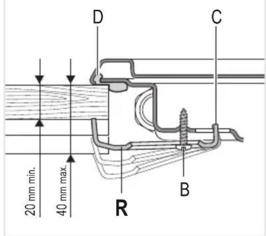
Fig. 4.5 Fig. 4.4
PROVISION FOR VENTILATION
- The appliance should be installed into a room or space with an air supply in accordance with the current version of BS 5440-2: 2000.
- For rooms with a volume of less than 5m ^3 - permanent ventilation of 100 cm ^2 free area must be provided.
- For rooms with a volume of between 5 m ^3 and 10 m ^3 a permanent ventilation of 50 cm ^2 free area will be required unless the room has a door which opens directly to the outside air in which case no permanent ventilation is required.
- For rooms with a volume greater than 10m^3 - no permanent ventilation is required.
Note: Regardless of room size, all rooms containing the appliance must have direct access to the outside air via an openable window or equivalent.
- Where there are other fuel burning appliances in the same room, the current version of BS 5440-2: 2000 should be consulted to determine the correct amount of free area ventilation requirements.
This appliance is supplied for use on NATURAL GAS or LPG (check the gas regulation label attached on the appliance).
- Appliances supplied for use on NATURAL GAS are adjusted for this gas only and cannot be used on any other gas (LPG) without modification. The ap manufactured for conversion to LPG.
- Appliances supplied for use on LPG are adjusted for this gas only and cannot be used on any other gas (NATURAL GAS) without modification. The app manufactured for conversion to NATURAL GAS.
If the NATURAL GAS/LPG conversion kit is not supplied with the appliance this kit can be purchased by contacting the After-Sales Service.
INSTALLATION & SERVICE REGULATIONS (UNITED KINGDOM)
It is a legal requirement that all gas appliances are Installed & Serviced by a competent person in accordance with the current editions of the following Standards & Regulations or those regulations appropriate to the geographical region in which they are to be installed:
• Gas Safety (Installation & Use) Regulations
• Building Regulations
• British/European Standards
• Regulations for Electrical Installation
Installation and service of any gas product must be made by a suitably registered person competent on the type of product being installed or serviced and holding a valid certificate of competence for the work being carried out. Currently competence is the Accredited Certification Scheme (ACS) or N/SVQ that has been aligned to the ACS.
It is also a requirement that all businesses or self employed installers are members of a class of person approved by the Health and Safety Executive.
Failure to install the appliance correctly could invalidate any manufacturers warranty and lead to prosecution under the above quoted regulations.
GAS CONNECTION
Cat: II 2H 3+
Installation to Natural Gas
Installation to Natural Gas must conform to the Code of Practice, etc.
The supply pressure for Natural Gas is 20 mbar.
The installation must conform to the relevant British/European Standards.
Installation to LP Gas
When operating on Butane gas a supply pressure of 28-30 mbar is required.
When using Propane gas a supply pressure of 37 mbar is required.
The installation must conform to the relevant British/European Standards.
Warning: Only a suitably qualified and registered installer, also with technical knowledge of electricity should install the appliance.
He should observe the Regulations and Codes of Practice governing such installation of gas appliances.
Note: It is recommended that the gas connection to the appliance is installed with a flexible hose connecting tube made to BS669.
Notes:
- Flexible hoses can be used where the sited ambient temperature of the hose does not exceed 70°C. These hoses must be manufactured in accordance with BS669 part 1 and be of the correct construction for the type of gas being used.
- Gas hoses designed for natural gas MUST NOT be used for supplying LPG gas (LPG gas hoses can be identified by a either a red band or stripe on the rubber outer coating of the hose).
The hose should not be crushed or trapped or be in contact with sharp or abrasive edges.
IMPORTANT! It is the responsibility of the gas installer to ensure that the product is fully tested and commissioned in accordance with current regulations to ensure there are no gas escapes.
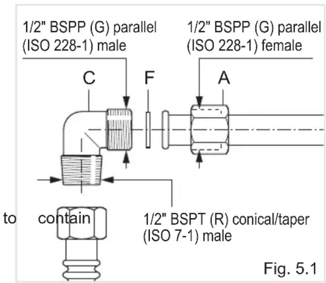
The fitting (fig. 5.1) is made up of:
- 1 nut "A"
- 1 elbow fitting "C"
- gasket "F"
Connection to the Gas Supply
- Be careful when flexible pipes are used that they do not come into contact with moving parts.
- To maintain the thickness of 3cm , the hob is fitted with a channel the connection pipe.
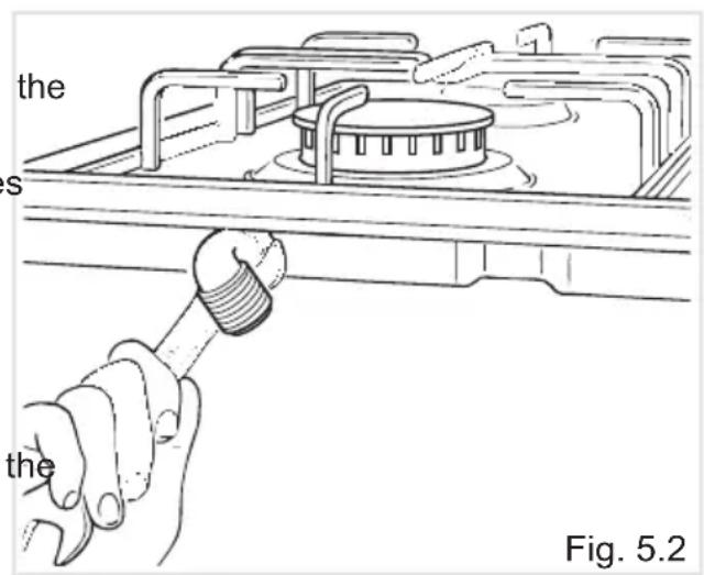
- The gas inlet union can be turned in the direction required after the elbow fitting "C" and nut "A" connection (figure 5.1) has been slackened (fig. 5.2).
- Never put it in the horizontal or vertical position.
- Never attempt to turn the elbow "C" without having first slackened off relative lock nut "A".
- The gasket "F" (fig. 5.1) guarantees the seal of the gas connection. It is recommended that it be replaced whenever it shows even the slightest deformation or imperfection.
If installation is to be carried out using a flexible connector (to BS669), then following points must be adhered to:
Note: The gas installation pipes and the final connection to the appliance connecting pipe
shall be of a sufficient size to maintain the heat output of the appliance as specified on the rating plate.
- The appliance flexible connector should not be subject to undue forces, either in normal use whilst being connected or disconnected.
- The appliance flexible connector should not be subject to excessive heat exposure to flue products or by contact with hot surfaces.
- The socket into which the plug of the appliance flexible connector fits should be permanently attached to a firmly fixed gas installation pipe and positioned such that the hose hangs freely downwards in a natural loop and does not touch the floor.
- The appliance flexible connector should be positioned such that it will not suffer mechanical damage; eg abrasion from the surrounding kitchen furniture which may be moved in use, such as a door or drawer, or by being trapped by a stability device.
- The bayonet fitting should be accessible for disconnection after moving the appliance.
REPLACEMENT OF THE INJECTORS
If the injectors are not supplied they can be obtained from the After-Sales Service.
Select the injectors to be replaced according to the "Table for the choice of the injectors".
The nozzle diameters, expressed in hundredths of a millimetre, are marked on the body of each injector.
REPLACEMENT OF THE INJECTORS OF THE COOKTOP BURNERS
To replace the injectors proceed as follows:
- Remove pan supports and burners from the cooktop.
- Using a wrench, substitute the nozzle injectors "J" (figs. 5.3, 5.4) with those most suitable for the kind of gas for which it is to be used.
The burners are conceived in such a way so as not to require the regulation of the primary air.
ADJUSTING OF THE MINIMUM OF THE TOP BURNERS
In the minimum position the flame have a length of about 4 mm and must remain lit even with a quick turn from the maximum position to that of minimum.
The flame adjustment is done in following way:
• Turn on the burner.
• Turn the tap to the MINIMUM position.
• Take off the knob.
- With a thin screwdriver turn the screw "A" until adjustment is correct (fig. 5.5).
Normally for LPG, tighten up the regulation screw.
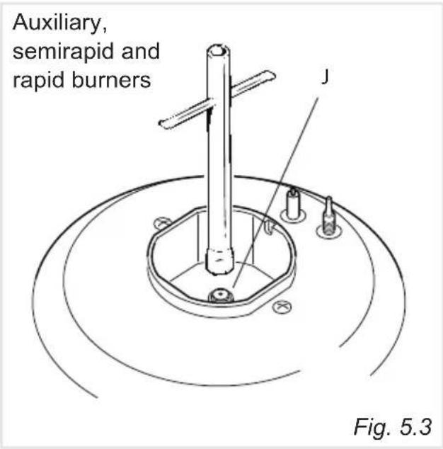
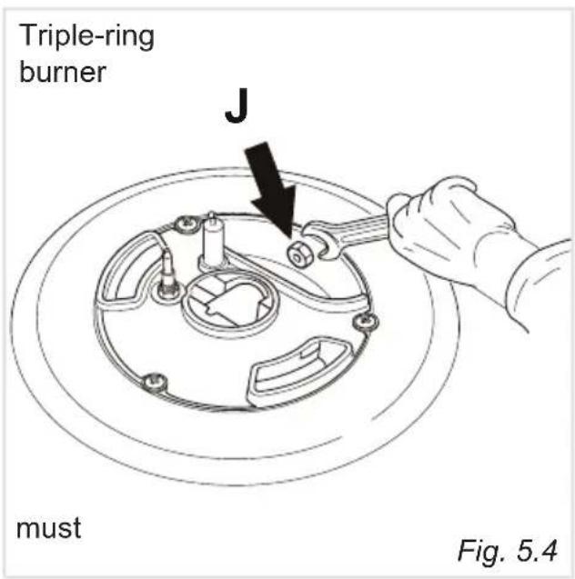
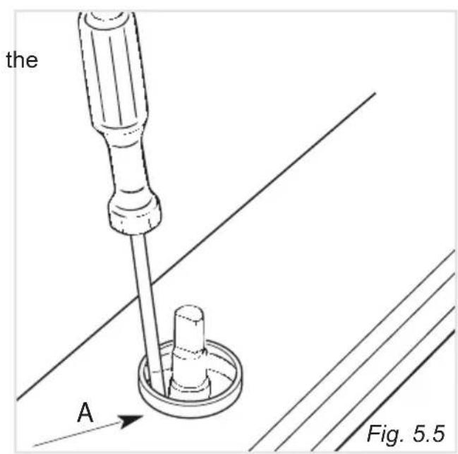
TABLE FOR THE CHOICE OF THE INJECTORS


Cat: II 2H 3+
| BURNERS | Nominal Power [kW] | Reduced Power [kW] | LPG G30/G31 28-30/37 mbar | Natural Gas G20 20 mbar |
| ∅ injector [1/100 mm] | ∅ injector [1/100 mm] | |||
| Auxiliary (A) 1,00 0,40 | 50 77 | |||
| Semirapid (SR) 1,75 | 0,45 66 101 | |||
| Rapid (R) 3,00 0,75 | 87 129 | |||
| Triple Ring (TR) 3,50 | 1,50 93 135 |
| AIR VENT NECESSARY FOR GAS COMBUSTION = (2 m3/h x kW) | |
| BURNERS Air necessary for combustion [m 3/h] | |
| Auxiliary (A) 2,00 | |
| Semirapid (SR) 3,50 | |
| Rapid (R) 6,00 | |
| Triple Ring (TR) 7,00 | |
LUBRICATION OF THE GAS TAPS
The operations must be executed by a qualified technician.
IMPORTANT: All intervention regarding installation maintenance and conversion of the appliance must be fulfilled with original factory parts.
The manufacturer declines any liability resulting from the non-compliance of this obligation.
6 - ELECTRICAL INSTALLATION
IMPORTANT: The appliance must be installed by a qualified technician according with the current local regulations and in compliance with the manufacturer instructions. Incorrect installation might cause harm and damage to people, animals or objects, for which the manufacturer accepts no responsibility.
Connection to a good earth wiring system is absolutely essential.
The manufacturer accepts no responsibility for any inconvenience caused by failure to comply with this rule.
Before carrying out any work on the electrical section of the appliance, it must be disconnected from the mains.
For your safety please read the following information:
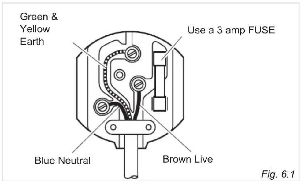
- The appliance must be connected to a 230 volts 50 cycle AC supply by means of a three pin socket, suitably earthed and should be protected by a 3 amp fuse in the plug.
- The appliance is supplied with a rewireable 13 amp 3 pin plug fitted with a 3 amp fuse. Should the fuse require replacement, it must be replaced with a fuse rated at 3 amp and approved to BS1362.
- If the mains plug is unsuitable for the socket outlet in your home or is removed for any other reason, then the cut off plug should be disposed of safely to prevent the hazard of electric shock.
- There is a danger of electric shock if the cut off plug is inserted into any 13 amp socket outlet.
• How to wire a 13 amp plug.
Important
The wires in the mains lead on this appliance are coloured in accordance with the following code:
Green and Yellow - Earth
Blue – Neutral
Brown – Live
As the colours may not correspond with the markings identifying the terminals in your plug proceed as follows:
— The green and yellow wire must be connected to the terminal in the plug which is marked with the letter “E” or with the earth symbol 1= or coloured green and yellow.
— The blue wire must be connected to the terminal marked "N" or coloured black.
— The brown wire must be connected to the terminal marked "L" or coloured red.
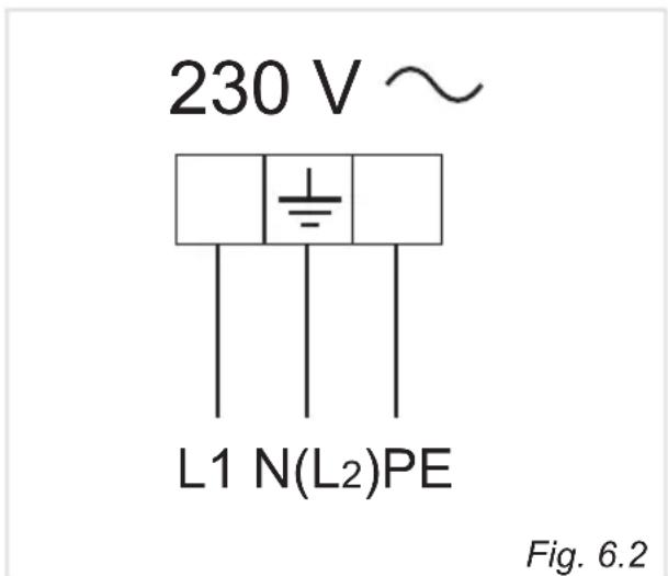
SECTION OF THE SUPPLY CABLE TYPE "H05V2V2-F"
resistant to temperatures of 90°C
230 V AC 50 Hz 3 x 0,75 mm ^4
REPLACING THER POWER SUPPLY CABLE
WARNING: If the power supply cable is damaged, it must be replaced only by an authorised service agent in order to avoid a hazard.
• The supply cable must be replaced with a cable of the same type.
- The electrical cable must be connected to the terminal board following the diagram of fig. 6.2.
7 - GUARANTEE
Your new “KENWOOD” product comes with 12-month guarantee covering all parts and labour.
If your appliance proves to be defective as a result of faulty materials or workmanship during the guarantee period, these parts will be repaired or replaced free of charge.
AFTER SALES SERVICE
Should you require service, spares or product information and advice:
• Please Telephone 0843 362 1934.
• Details of your purchase receipt will be required if you require service within the first 12-month of purchase.
-
The rights and benefits under this guarantee are additional to your statutory rights, which are not affected by this guarantee.
-
The manufacturer undertakes within the specified period, to repair or replace free of charge any parts of the appliance found to be defective provided that:
• We are promptly informed of the defect.
- The appliance is installed and used in accordance with the written instructions enclosed with the appliance.
- The appliance is used only on an electrical supply as indicated on the rating label fixed to the appliance.
- The appliance has not been altered in any way or subject to misuse or repaired by a person other than an authorised service agent.
-
No rights are given under this guarantee to a person acquiring the appliance second hand or for commercial, semi-commercial or communal use.
-
This guarantee applies throughout the UK and Channel Islands.
-
Any repaired or replacement appliances will be guaranteed on these terms for the unexpired portion of the guarantee.
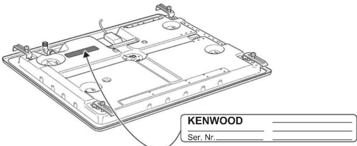
Fig. 7.1
The manufacturer cannot be held responsible for possible inaccuracies due to printing or transcription errors in the present booklet.
The manufacturer reserves the right to make all modifications to its products deemed necessary for manufacture or commercial reasons at any moment and without prior notice, without jeopardising the essential functional and safety characteristics of the appliances.
KENWOOD
- KENWOOD
- CONTENTS Page Number
- Dear Customer,
- DECLARATION OF CE CONFORMITY
- IMPORTANT SAFETY PRECAUTIONS AND RECOMMENDATIONS
- - FEATURES
- GAS BURNERS
- CONTROL PANEL DESCRIPTION
- NOTE:
- CAUTION:
- - HOW TO USE THE COOKTOP
- Caution!
- LIGHTING GAS BURNERS FITTED WITH SAFETY VALVE DEVICE
- AUXILIARY GRATE FOR SMALL PANS - Only for the model KHG 601 (fig. 2.3)
- CHOICE OF BURNER
- CORRECT USE OF THE TRIPLE-RING BURNER
- IMPORTANT:
- - CLEANING AND MAINTENANCE
- GENERAL ADVICE
- WARNING:
- CLEANING
- Attention!
- BURNERS AND GRIDS
- CORRECT REPLACEMENT OF THE AUXILIARY, SEMIRAPID AND RAPID BURNERS
- CORRECT POSITION OF THE TRIPLE RING BURNER
- Advice for the installer
- IMPORTANT
- WARNING
- - INSTALLATION
- TECHNICAL INFORMATION FOR THE INSTALLER
- FASTENING THE INSTALLATION BRACKETS (figs. 4.4, 4.5, 4.6)
- FASTENING THE COOKER TOP (figs. 4.4, 4.5, 4.6)
- PROVISION FOR VENTILATION
- INSTALLATION & SERVICE REGULATIONS (UNITED KINGDOM)
- GAS CONNECTION
- Installation to Natural Gas
- Installation to LP Gas
- Notes:
- Connection to the Gas Supply
- REPLACEMENT OF THE INJECTORS
- REPLACEMENT OF THE INJECTORS OF THE COOKTOP BURNERS
- ADJUSTING OF THE MINIMUM OF THE TOP BURNERS
- TABLE FOR THE CHOICE OF THE INJECTORS
- LUBRICATION OF THE GAS TAPS
- - ELECTRICAL INSTALLATION
- SECTION OF THE SUPPLY CABLE TYPE "H05V2V2-F"
- resistant to temperatures of 90°C
- REPLACING THER POWER SUPPLY CABLE
- - GUARANTEE
- AFTER SALES SERVICE
Brand : KENWOOD
Model : KHG 602
Category : Cooker