SG725 - Remote control toy SAB - Free user manual and instructions
Find the device manual for free SG725 SAB in PDF.


User questions about SG725 SAB
0 question about this device. Answer the ones you know or ask your own.
Ask a new question about this device
Download the instructions for your Remote control toy in PDF format for free! Find your manual SG725 - SAB and take your electronic device back in hand. On this page are published all the documents necessary for the use of your device. SG725 by SAB.
USER MANUAL SG725 SAB
- Carefully check your model before each flight to ensure it is airworthy.
- Consider flying only in areas dedicated to the use of model helicopters.
- Check and inspect the flying area to ensure it is clear of people obstacles.
- Rotor blades can rotate at very high speeds! Be aware of the danger they pose.
- Always keep the model at a safe distance from other pilots and spectators.
- Avoid maneuvers with trajectories towards a crowd.
- Always maintain a safe distance from the model.
Goblin URUKAY CARBON Manual
Release 1.1 - November 2016
WORLD DISTRIBUTION
www.goblin-helicopter.com
For sales inquiries, please email: sales@goblin-helicopter.com
For info inquiries, please email: support@goblin-helicopter.com
Attention: If you are a consumer and have questions or need of assistance, please contact in a first time the Goblin retailer where you made the purchase
EUROPEAN DISTRIBUTION
www.sabitaly.it
For sales inquiries, please email: sales@sabitaly.it
For info inquiries, please email: info@sabitaly.it
Attention: If you are a consumer and have questions or need of assistance, please contact in a first time the Goblin retailer where you made the purchase
Please read this user manual carefully, it contains instructions for the correct assembly of the model. Please refer to the web site www.goblin-helicopter.com for updates and other important information.
VERY IMPORTANT
In the Manual bag you will find a product card your with serial number. Please take a moment to register your kit online via our web site at:
http://www.goblin-helicopter.com

text_image
QR code image containing encoded data, no visible human-readable textIt is extremely important that you take a moment to register your helicopter with us. This is the only way to ensure that you are properly informed about changes to your kit, such as upgrades, retrofits and other important developments. SAB Heli Division cannot be held responsible for issues arising with your model and will not provide support unless you register your serial number.
The Serial number is also engraved in the Aluminum Main Plate.
Thank you for your purchase, we hope you enjoy your new Goblin helicopter!
SAB Heli Division
INDEX
1 – Specifications
2 - Important Notes
3-Components and Box
4 – Carbon frame Assembly
5 – Trasmission Assembly
6 - Main Rotor HF3C
7 – Assembling The Modules
8 - Installation of Swashplate Servos
9 - Installation of The Motor
10 – Installation of The ESC
11 - Installation of Flybarless Unit and RX
12 - Tail Assembly
13 – Installation of the Boom, Canopy
14-Battery
15 – In flight
16 - Maintenance
17 - Exploded Views
18 – Spare Parts
SPECIFICATIONS
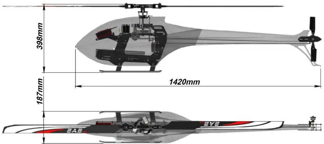
text_image
398mm 187mm 1420mm SAS SASMain rotor diameter: 1654mm with 730mm blades.
Main blade length: up to 750mm
Tail rotor diameter: 304mm (284mm for EG version)
Tail blade length: 115mm (105mm for EG version)
Main shaft diameter: 12mm
Tail shaft diameter: 6mm
Spindle diameter: 10mm
Motor size: Maximum 64mm diameter, maximum height 72mm
Battery compartment: 60x58x350mm (adaptable to 75x58x350mm)
IMPORTANT NOTES
*This radio controlled helicopter is not a toy.
*This radio controlled helicopter can be very dangerous.
*This radio controlled helicopter is a technically complex device which has to be built and handled very carefully.
*This radio controlled helicopter must be built following these instructions. This manual provides the necessary information to correctly assemble the model. It is necessary to carefully follow all the instructions.
*Inexperienced pilots must be monitored by expert pilots.
*All operators must wear safety glasses and take appropriate safety precautions.
* A radio controlled helicopter must only be used in open spaces without obstacles, and far enough from people to minimize the possibility of accidents or of injury to property or persons.
*A radio controlled helicopter can behave in an unexpected manner, causing loss of control of the model, making it very dangerous.
*Lack of care with assembly or maintenance can result in an unreliable and dangerous model.
*Neither SAB Heli Division nor its agents have any control over the assembly, maintenance and use of this product. Therefore, no responsibility can be traced back to the manufacturer. You hereby agree to release SAB Heli Division from any responsibility or liability arising from the use of this product.
SAFETY GUIDELINES
*Fly only in areas dedicated to the use of model helicopters.
*Follow all control procedures for the radio frequency system.
*It is necessary that you know your radio system well. Check all functions of the transmitter before every flight.
*The blades of the model rotate at a very high speed; be aware of the danger they pose and the damage they may cause.
*Never fly in the vicinity of other people.
LIMITED WARRANTY.
SAB Heli Division reserves the right to change or modify this warranty without notice and disclaims all other warranties, express or implied. (a) This warranty is limited to the original Purchaser ("Purchaser") and is not transferable. REPLACEMENT AS PROVIDED UNDER THIS WARRANTY IS THE EXCLUSIVE REMEDY OF THE PURCHASER This warranty covers only those Products purchased from an authorized SAB Heli Division dealer. Third party transactions are not covered by this warranty. Proof of purchase is required for warranty claims. (b) Limitations- SAB HELI DIVISION MAKES NO WARRANTY OR REPRESENTATION, EXPRESS OR IMPLIED, ABOUT NONIFRINGEMENT, MERCHANTABILITY OR FITNESS FOR A PARTICULAR PURPOSE OF THE PRODUCT. THE PURCHASER ACKNOWLEDGES THAT THEY ALONE HAVE DETERMINED THAT THE PRODUCT WILL SUITABLY MEET THE REQUIREMENTS OF THE PURCHASER'S INTENDED USE.
(c) Purchaser Remedy- SAB Heli Division's sole obligation hereunder shall be that SAB Heli Division will, at its option, replace any Product determined by SAB Heli Division to be defective In the event of a defect, this is the Purchaser's exclusive remedy. Replacement decisions are at the sole discretion of SAB Heli Division. This warranty does not cover cosmetic damage or damage due to acts of God, accident, misuse, abuse, negligence, commercial use, or modification of or to any part of the Product. This warranty does not cover damage due to improper installation, operation, maintenance or attempted repair by anyone
DAMAGE LIMITS.
SAB HELI DIVISION SHALL NOT BE LIABLE FOR SPECIAL, INDIRECT OR CONSEQUENTIAL DAMAGES, LOSS OF PROFITS OR PRODUCTION OR COMMERCIAL LOSS IN ANY WAY CONNECTED WITH THE PRODUCT, WHETHER SUCH CLAIM IS BASED IN CONTRACT, WARRANTY, NEGLIGENCE, OR STRICT LIABILITY. Further, in no event shall the liability of SAB Heli Division exceed the individual price of the Product on which liability is asserted. As SAB Heli Division has no control over use, setup, final assembly, modification or misuse, no liability shall be assumed nor accepted for any resulting damage or injury. By the act of use, setup or assembly the user accepts all resulting liability. If you as the Purchaser or user are not prepared to accept the liability associated with the use of this Product, you are advised to return this Product immediately in new and unused condition to the place of purchase.
NOTES FOR ASSEMBLY
Please refer to this manual for assembly instructions for this model.
Follow the order of assembly indicated. The instructions are divided into chapters, which are structured in a way that each step is based on the work done in the previous step. Changing the order of assembly may result in additional or unnecessary steps.
Use thread lockers and retaining compounds as indicated. In general, each bolt or screw that engages with a metal part requires thread lock.
It is necessary to pay attention to the symbols listed below:
Important
Use retaining compound (eg Loctite 648)
Use CA Glue

Bag xx
Indicates that for this assembly phase you need materials that are in Bag xx.
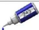
Use retaining compound (eg Loctite 243)
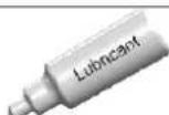
Use Proper Lubricant
ADDITIONAL COMPONENTS REQUIRED
*Electric Motor: 400 - 560Kv
Maximum diameter 64mm,
Maximum height 72mm,
Pinion shaft diameter 6/8mm
*Speed controller: minimum 120A, suggest 160A
*Batteries: 12S-5000 mAh
*1 flybarless 3 axis control unit
*Radio power system, if not integrated with the ESC
*3 cyclic servos
*1 tail rotor servo
*6 channel radio control system on 2.4 GHz
(See configuration examples on page 17)
TOOLS, LUBRICANTS, ADHESIVES
*Generic pliers
*Hexagonal driver, size 1.5,2,2.5,3,4mm
*4mm T-Wrench
*5.5mm Socket wrench (for M3 nuts)
*8mm Hex fork wrench (for M5 nuts)
*Medium threadlocker (eg. Loctite 243)
*Strong retaining compound (eg. Loctite 648)
*Spray lubricant (eg. Try-Flow Oil)
*Grease ( eg. Microlube GL261 )
*Cyanoacrylate adhesive
*Pitch Gauge (for set-up)
*Soldering equipment (for motor wiring)
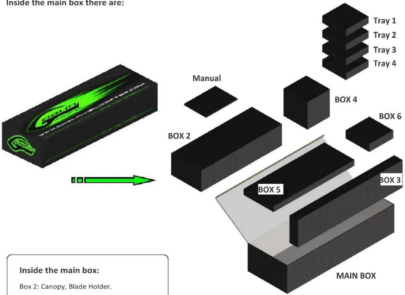
Inside the main box there are:
text_image
Inside the main box there are: Tray 1 Tray 2 Tray 3 Tray 4 Tray 5 BOX 2 Manual BOX 4 BOX 6 BOX 3 MAIN BOX Inside the main box: Box 2: Canopy, Blade Holder.Inside the main box:
Box 2: Canopy, Blade Holder.
Box 3: Boom, Carbon rod, Blades.
Box 4: Mechanical parts in 4 trays:
Tray 1: Main rotor.
Tray 2: Carbon frame and tail rotor.
Tray 3: Transmission.
Tray 4: Main structure.
Box 5: Bags, Carbon parts.
Box 6: Tail Fin, Tail Blades.
The assembly process is described in the following chapters. Each chapter provides you with the box, bag and/or foam tray numbers you will need for that chapter. The information is printed in a green box in the upper right hand corner of the page at the beginning of every chapter.
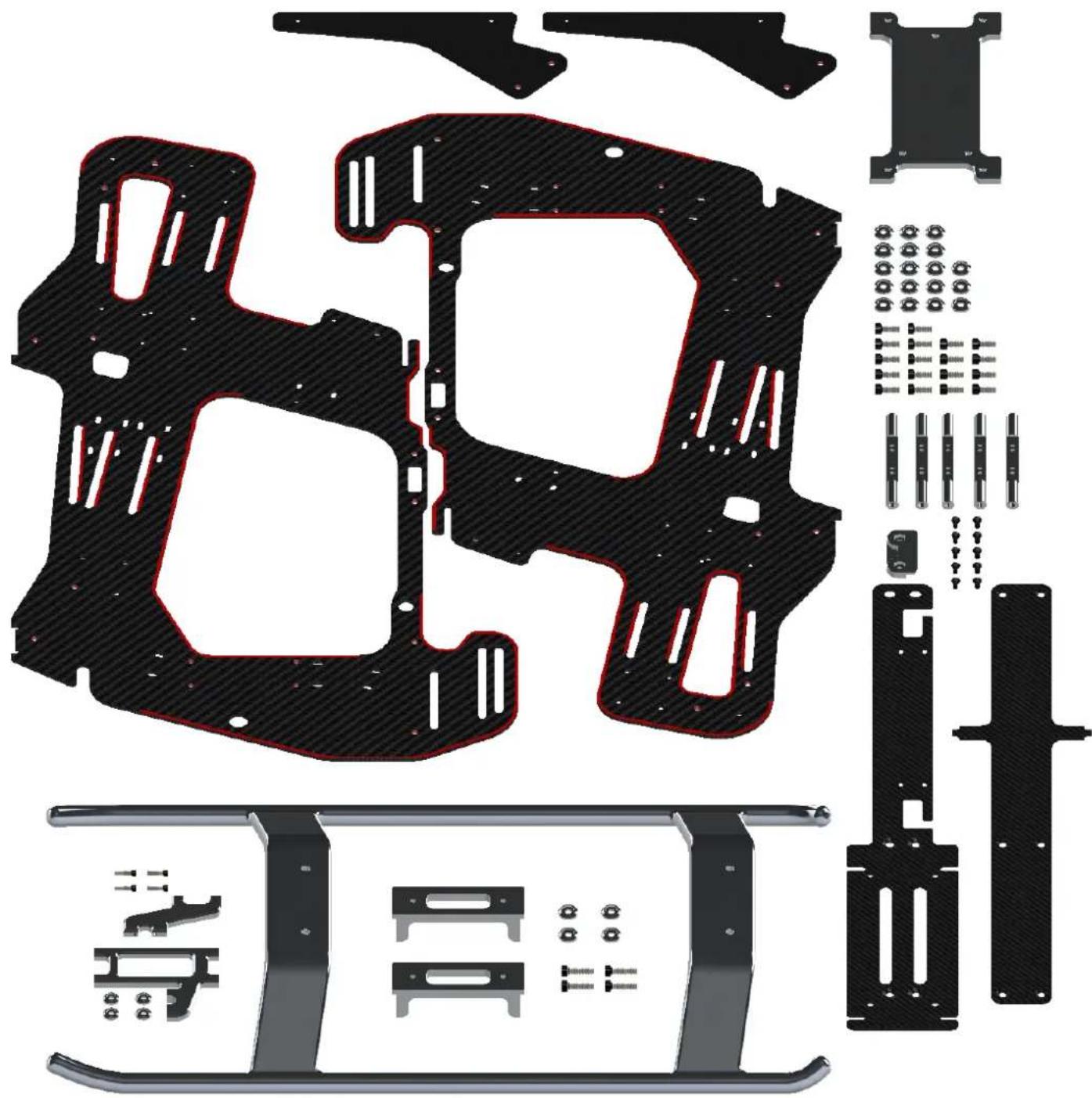
4-Carbon Frame

The manufacturing process of the carbon parts often leaves micro-burrs and sharp edges. We recommend de-burring the edges to minimize the risks of electrical wire cuts, etc. Very important in red line zone.
natural_image
Exploded view of a mechanical assembly with cutouts and component footprints (no text or symbols)Battery / ESC Position
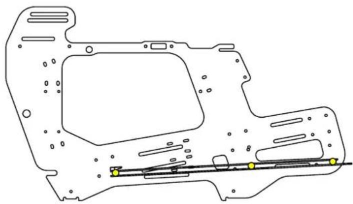
It is possible to place the battery support in many positions. The two main positions are illustrated.
(Light Batteries < 1500-1600g)
( Heavy Batteries > 1600-1700g )
natural_image
Technical line drawing of a mechanical component with no visible text or symbols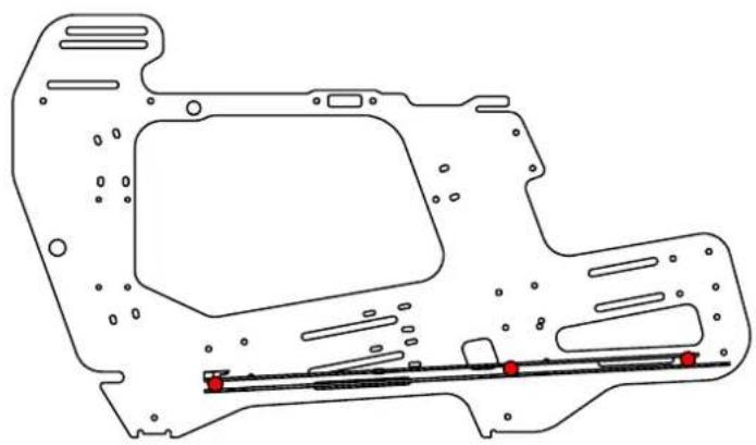
natural_image
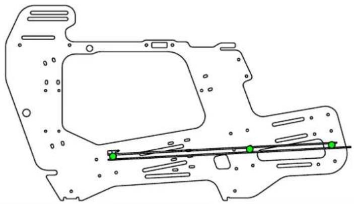
Technical line drawing of a mechanical component with no visible text or symbolsHere is showed another position. It allows you to raise the center of gravity of the model.
natural_image
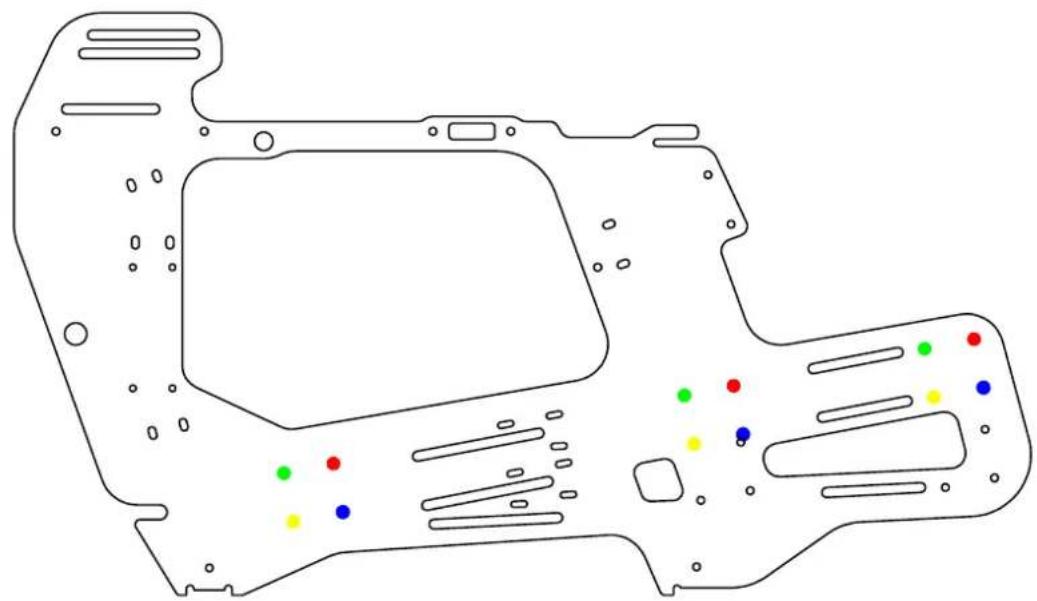
Technical line drawing of a mechanical component with internal features and a central rod (no text or symbols)The three previous positions are in relation to the position "top" of the ESC. If you want, you can install the ESC in a bottom position ( Please see page 19 ).
In this case you have to install the battery support in the one of these.
pie
| Color | Value | |-------|-------| | Red | 10 | | Green | 8 | | Yellow| 6 | | Blue | 5 |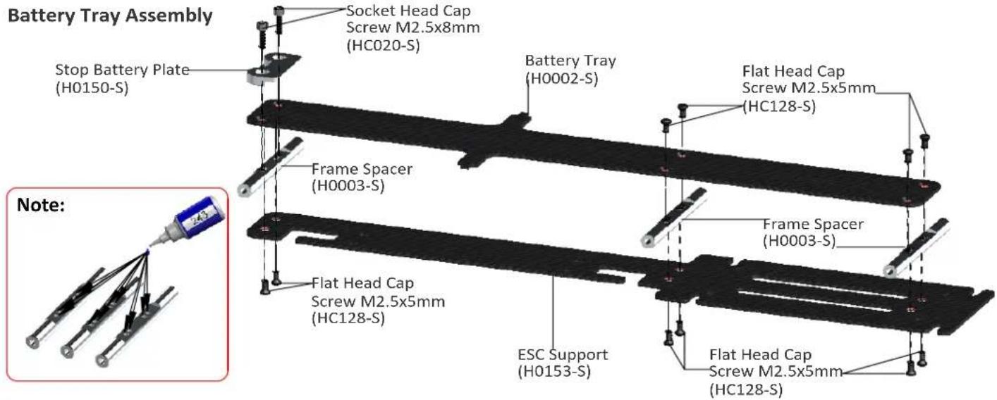
text_image
Battery Tray Assembly Stop Battery Plate (H0150-S) Socket Head Cap Screw M2.5x8mm (HC020-S) Battery Tray (H0002-S) Flat Head Cap Screw M2.5x5mm (HC128-S) Frame Spacer (H0003-S) Frame Spacer (H0003-S) Flat Head Cap Screw M2.5x5mm (HC128-S) ESC Support (H0153-S) Flat Head Cap Screw M2.5x5mm (HC128-S) Note:Left Main Frame Assembly
text_image
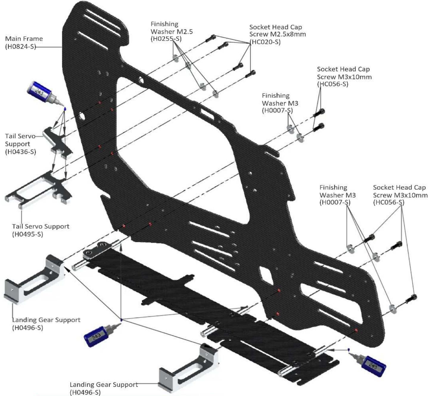
Main Frame (H0824-S) 243 Tail Servo Support (H0436-S) Tail Servo Support (H0495-S) Finishing Washer M2.5 (H0255-S) Socket Head Cap Screw M2.5x8mm (HC020-S) Finishing Washer M3 (H0007-S) Socket Head Cap Screw M3x10mm (HC056-S) Finishing Washer M3 (H0007-S) Socket Head Cap Screw M3x10mm (HC056-S) Landing Gear Support (H0496-S) Landing Gear Support (H0496-S)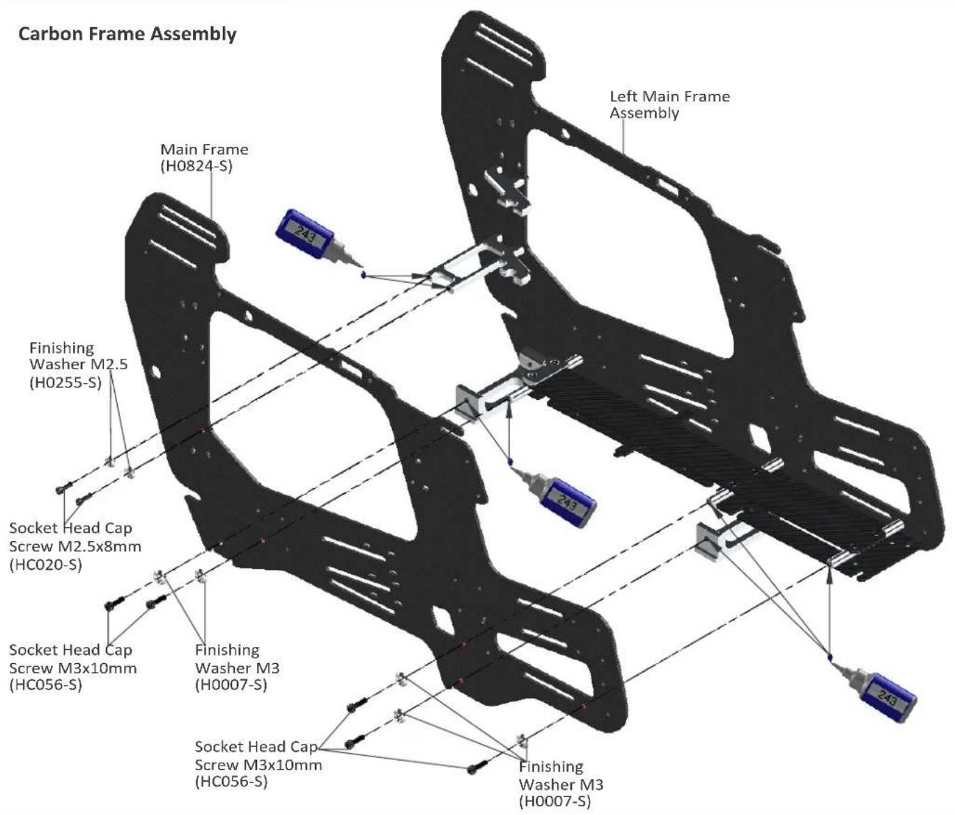
text_image
Carbon Frame Assembly Main Frame (H0824-S) 243 Left Main Frame Assembly Finishing Washer M2.5 (H0255-S) 243 Socket Head Cap Screw M2.5x8mm (HC020-S) Socket Head Cap Screw M3x10mm (HC056-S) Finishing Washer M3 (H0007-S) Socket Head Cap Screw M3x10mm (HC056-S) Finishing Washer M3 (H0007-S)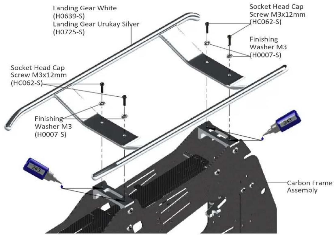
text_image
Landing Gear White (H0639-S) Landing Gear Urukay Silver (H0725-S) Socket Head Cap Screw M3x12mm (HC062-S) Finishing Washer M3 (H0007-S) Socket Head Cap Screw M3x12mm (HC062-S) Finishing Washer M3 (H0007-S) Carbon Frame AssemblyTop ESC Support Assembly
text_image
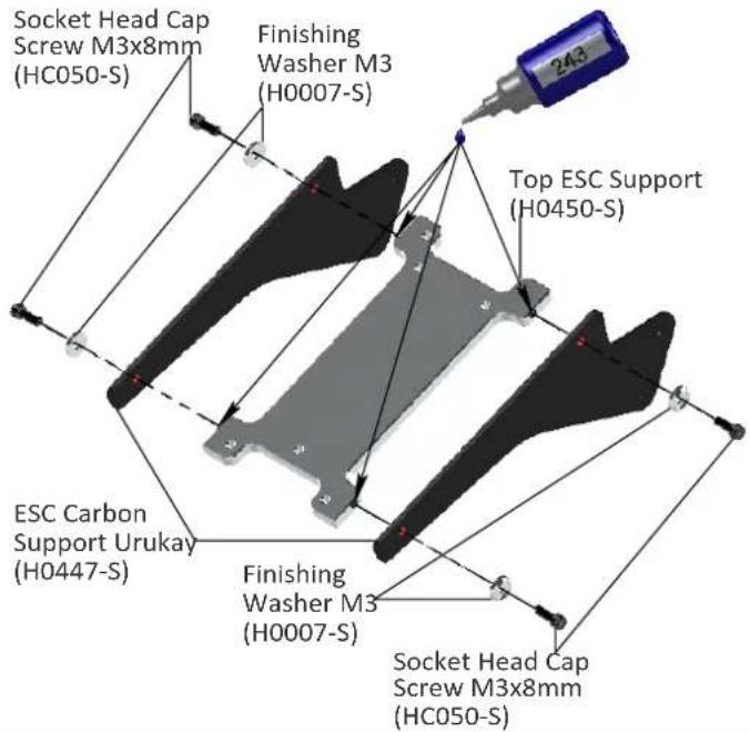
Socket Head Cap Screw M3x8mm (HC050-S) Finishing Washer M3 (H0007-S) Top ESC Support (H0450-S) ESC Carbon Support Urukay (H0447-S) Finishing Washer M3 (H0007-S) Socket Head Cap Screw M3x8mm (HC050-S)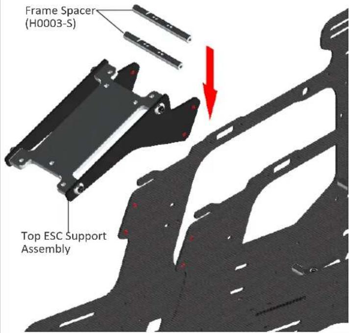
text_image
Frame Spacer (H0003-S) Top ESC Support Assembly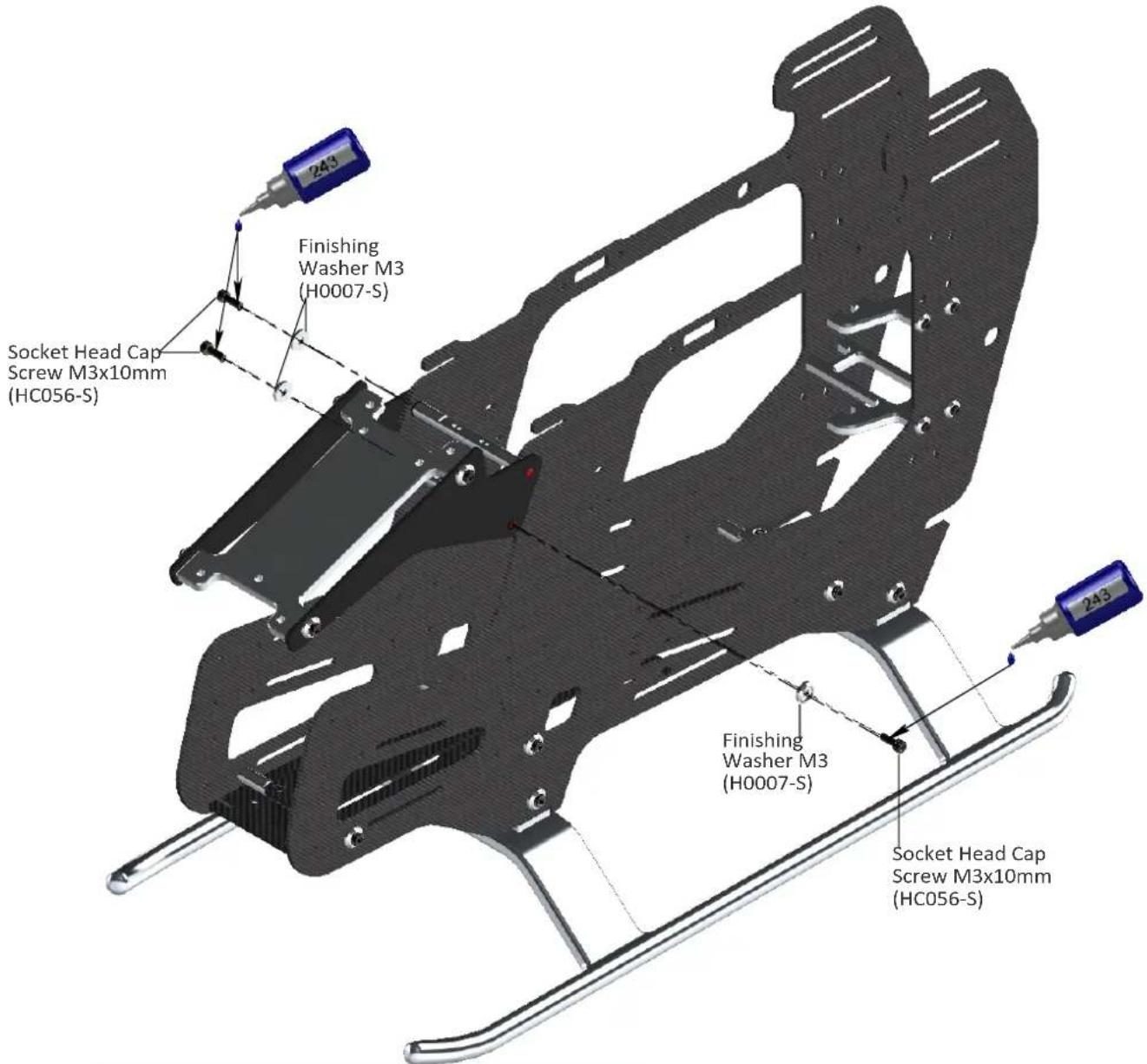
text_image
243 Finishing Washer M3 (H0007-S) Socket Head Cap Screw M3x10mm (HC056-S) Finishing Washer M3 (H0007-S) 243 Socket Head Cap Screw M3x10mm (HC056-S)
text_image
Bearing Ø 12x Ø 24x6mm (HC426-S) Bearing Support Assembly (H0024-S) Already Assembled Socket Head Cap Screw M3x10mm (HC056-S) Servo Support (H0010-S) Column (H0018-S) 648 Flat Head Cap Screw M2.5x5mm (HC128-S) Socket Head Cap Screw M3x10mm (HC056-S) Column (H0018-S) Bearing Ø 10x Ø 19x5mm (HC422-S) Already Assembled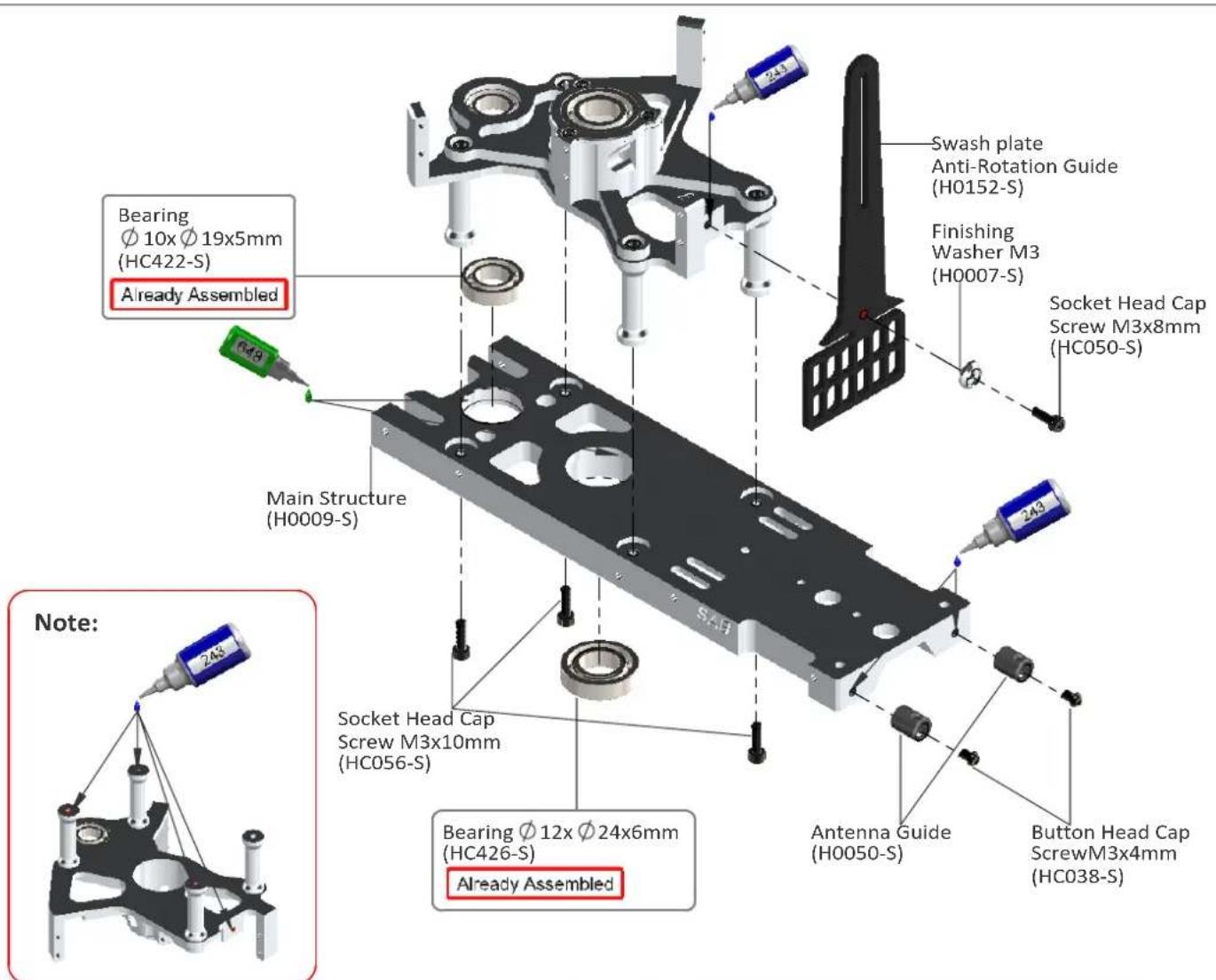
text_image
Swash plate Anti-Rotation Guide (H0152-S) Finishing Washer M3 (H0007-S) Socket Head Cap Screw M3x8mm (HC050-S) Bearing Ø 10x Ø 19x5mm (HC422-S) Already Assembled Main Structure (H0009-S) Socket Head Cap Screw M3x10mm (HC056-S) Bearing Ø 12x Ø 24x6mm (HC426-S) Already Assembled Antenna Guide (H0050-S) Button Head Cap ScrewM3x4mm (HC038-S) Note:Note:
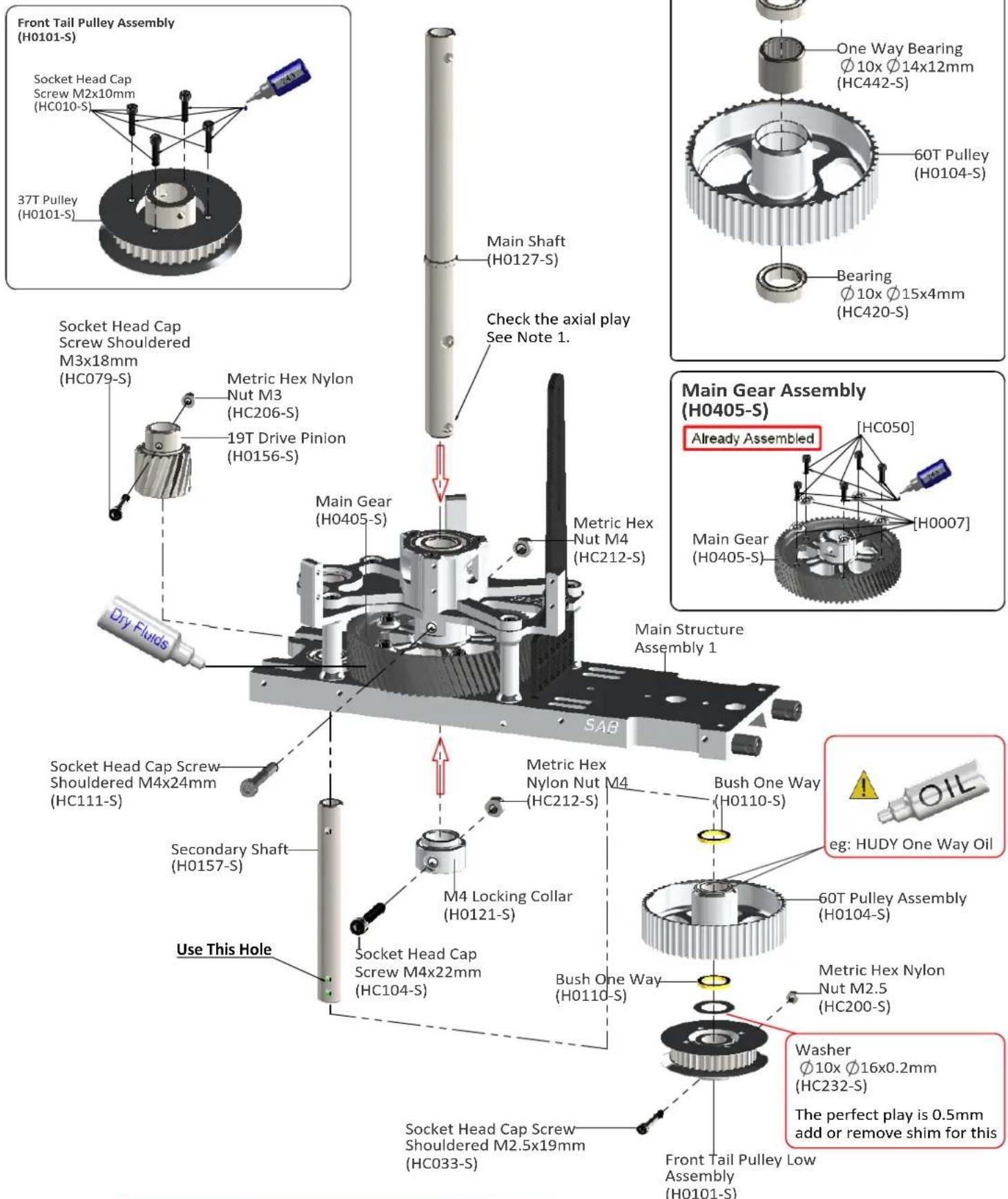
When you tighten the collar (H0121-S) on the main shaft, ensure there is no axial play.
Push down the main shaft while pulling up the locking collar. Tighten the screw M4x22 at this time.
text_image
Front Tail Pulley Assembly (H0101-S) Socket Head Cap Screw M2x10mm (HC010-S) 37T Pulley (H0101-S) Main Shaft (H0127-S) Check the axial play See Note 1. Socket Head Cap Screw Shouldered M3x18mm (HC079-S) Metric Hex Nylon Nut M3 (HC206-S) 19T Drive Pinion (H0156-S) Main Gear (H0405-S) Metric Hex Nut M4 (HC212-S) Main Structure Assembly 1 Dry Fluids SAB Main Gear Assembly (H0405-S) Already Assembled [HC050] Main Gear (H0405-S) [H0007] Main Structure Assembly 1 Socket Head Cap Screw Shouldered M4x24mm (HC111-S) Secondary Shaft (H0157-S) Use This Hole Metric Hex Nylon Nut M4 (HC212-S) M4 Locking Collar (H0121-S) Socket Head Cap Screw M4x22mm (HC104-S) Bush One Way (H0110-S) Bush One Way (H0110-S) 60T Pulley Assembly (H0104-S) Metric Hex Nylon Nut M2.5 (HC200-S) Washer Ø10x Ø16x0.2mm (HC232-S) The perfect play is 0.5mm add or remove shim for this Front Tail Pulley Low Assembly (H0101-S)Tail Belt Idler Assembly [H0834-S]
text_image
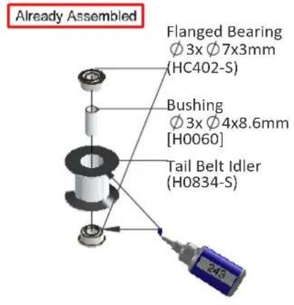
Already Assembled Flanged Bearing Ø 3x Ø7x3mm (HC402-S) Bushing Ø 3x Ø4x8.6mm [H0060] Tail Belt Idler (H0834-S)Belt Tensioner Arm Assembly [H0834-S]
text_image
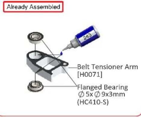
Already Assembled Belt Tensioner Arm [H0071] Flanged Bearing Ø 5x Ø 9x3mm (HC410-S)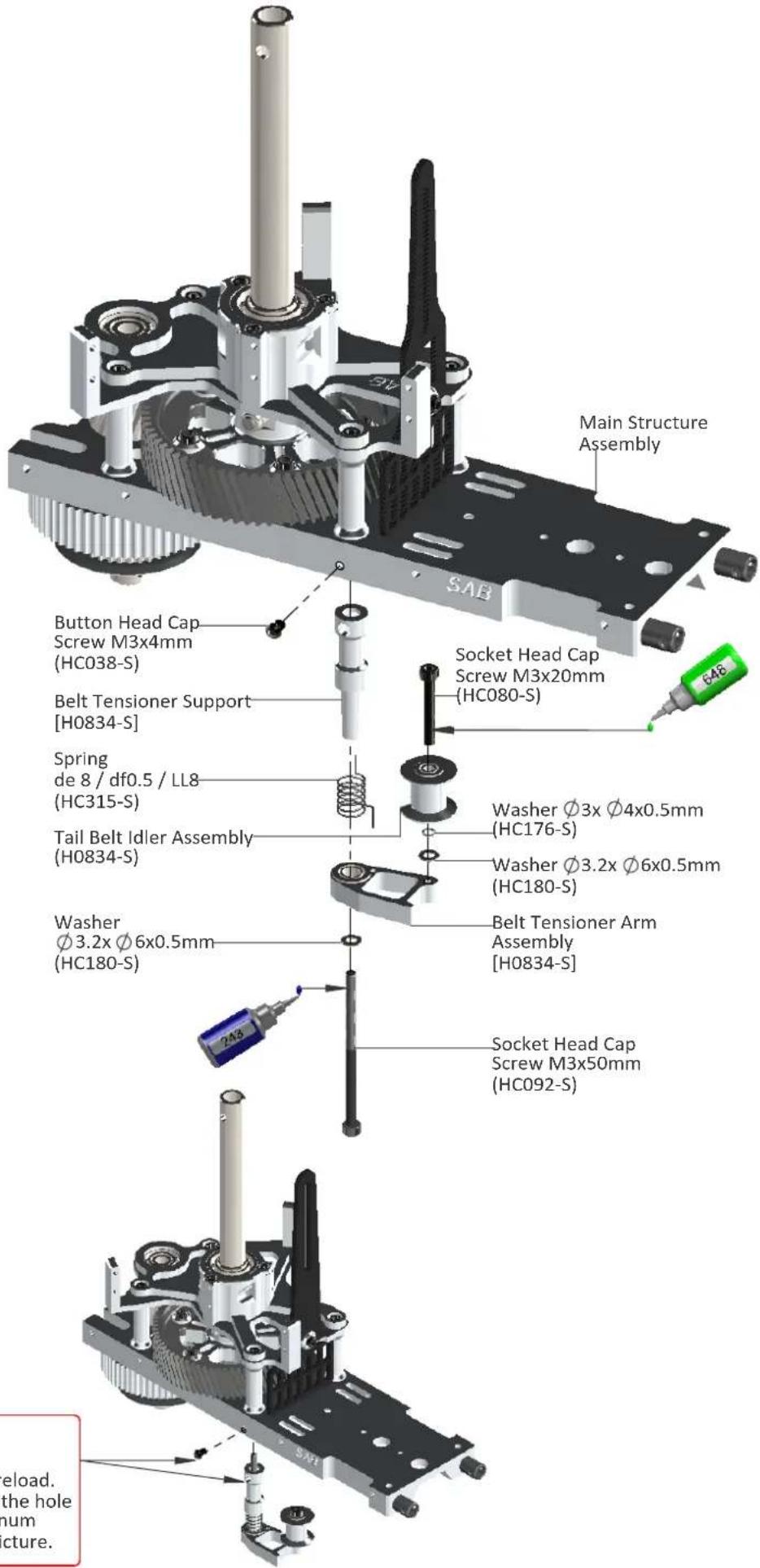
text_image
Main Structure Assembly SAB Button Head Cap Screw M3x4mm (HC038-S) Belt Tensioner Support [H0834-S] Spring de 8 / df0.5 / LL8 (HC315-S) Tail Belt Idler Assembly (H0834-S) Washer Ø3.2x Ø6x0.5mm (HC180-S) Socket Head Cap Screw M3x20mm (HC080-S) Socket Head Cap Screw M3x20mm (HC080-S) Washer Ø3x Ø4x0.5mm (HC176-S) Washer Ø3.2x Ø6x0.5mm (HC180-S) Belt Tensioner Arm Assembly [H0834-S] Socket Head Cap Screw M3x50mm (HC092-S) Download. the hole num picture.Note:
Position without preload. Insert the screw in the hole through the aluminum support as in the picture.
text_image
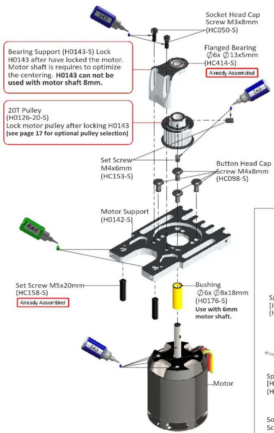
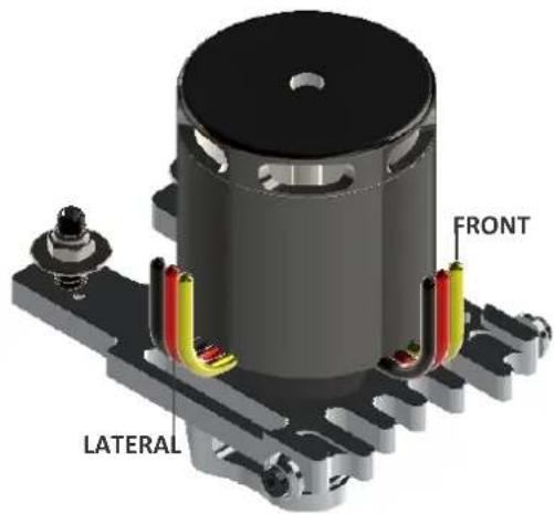
Socket Head Cap Screw M3x8mm (HC050-S) Flanged Bearing Ø6x Ø13x5mm (HC414-S) Already Assembled Bearing Support (H0143-S) Lock H0143 after have locked the motor. Motor shaft is requires to optimize the centering. H0143 can not be used with motor shaft 8mm. 20T Pulley (H0126-20-S) Lock motor pulley after locking H0143 (see page 17 for optional pulley selection) Set Screw M4x6mm (HC153-S) Button Head Cap Screw M4x8mm (HC098-S) Motor Support (H0142-S) Set Screw M5x20mm (HC158-S) Already Assembled Bushing Ø6x Ø8x18mm (H0176-S) Use with 6mm motor shaft. 243 MotorNOTE: Wire Direction
Where is your ESC? ( See page 19 ).
ESC top position >> FRONT. ESC bottom position >> LATERAL.
text_image
FRONT LATERAL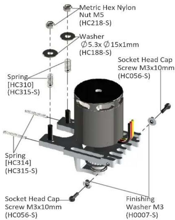
text_image
Metric Hex Nylon Nut M5 (HC218-S) Washer Ø 5.3x Ø 15x1mm (HC188-S) Socket Head Cap Screw M3x10mm (HC056-S) Spring [HC310] (HC315-S) Spring [HC314] (HC315-S) Socket Head Cap Screw M3x10mm (HC056-S) Finishing Washer M3 (H0007-S)Note for 6mm Motor Shaft
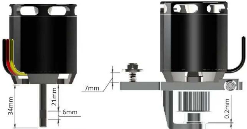
To maximize space for the batteries, it is advisable to shorten the motor shaft. Follow the dimensions given in this drawing. For the cut, you can use an electric tool like a "Dremel" with a cutoff disc.
Additionally, ensure the motor shaft has an appropriate 'flat' for one of the set screws.
text_image
34mm 21mm 6mm 7mm 0.2mmUniball Arm Assembly ... x2
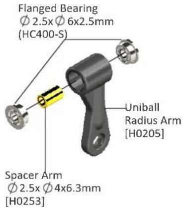
text_image
Flanged Bearing Ø 2.5x Ø 6x2.5mm (HC400-S) Spacer Arm Ø 2.5x Ø 4x6.3mm [H0253] Uniball Radius Arm [H0205]Radius Arm Assembly ... x2
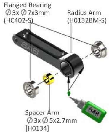
text_image
Flanged Bearing Ø 3x Ø 7x3mm (HC402-S) Radius Arm (H0132BM-S) Spacer Arm Ø 3x Ø 5x2.7mm [H0134]Center Hub Assembly
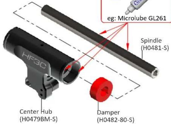
text_image
eg: Microlube GL261 Spindle (H0481-S) HF30 Center Hub (H0479BM-S) Damper (H0482-80-S)Note:
The HF3C head should be assembled with one, 1mm shim (HC230) on each side. The blade grips must move freely, but they should not move just under their own weight. After approximately 10/20 flights, please check preload, you can add one or two 0.2mm shim (HC232) if preload has changed.
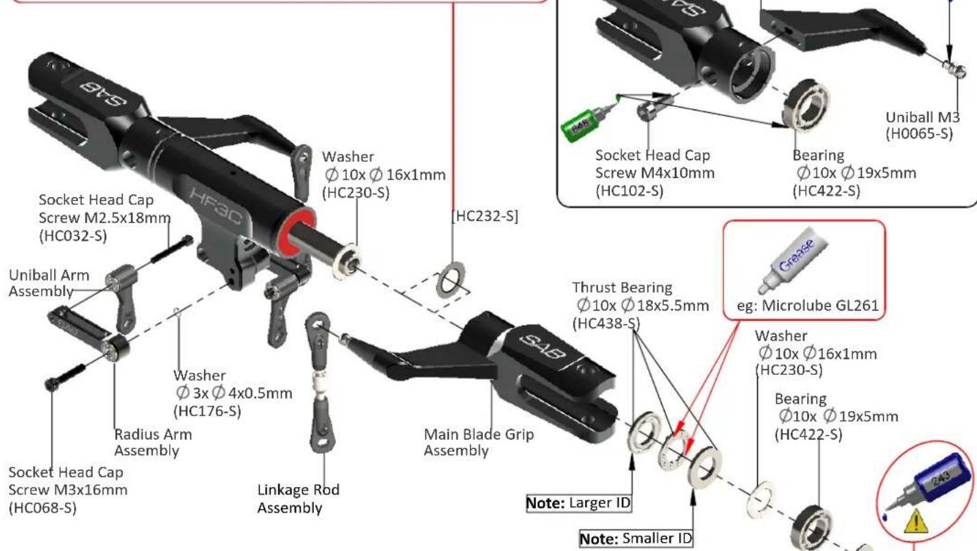
text_image
SYS HF30 Socket Head Cap Screw M2.5x18mm (HC032-S) Uniball Arm Assembly Socket Head Cap Screw M3x16mm (HC068-S) Radius Arm Assembly Washer Ø 3x Ø 4x0.5mm (HC176-S) Linkage Rod Assembly Washer Ø 10x Ø 16x1mm (HC230-S) Main Blade Grip Assembly Socket Head Cap Screw M4x10mm (HC102-S) Bearing Ø 10x Ø 19x5mm (HC422-S) Uniball M3 (H0065-S) Thrust Bearing Ø 10x Ø 18x5.5mm (HC438-S) Clease eg: Microlube GL261 Washer Ø 10x Ø 16x1mm (HC230-S) Bearing Ø 10x Ø 19x5mm (HC422-S) Note: Larger ID Note: Smaller IDLinkage Rod A Assembly ...x2
text_image
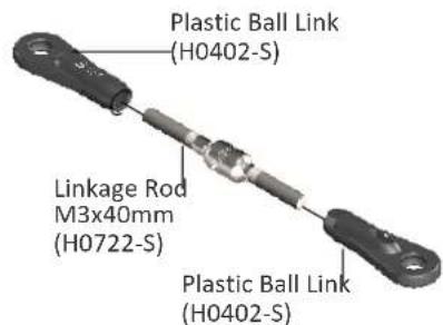
Plastic Ball Link (H0402-S) Linkage Rod M3x40mm (H0722-S) Plastic Ball Link (H0402-S)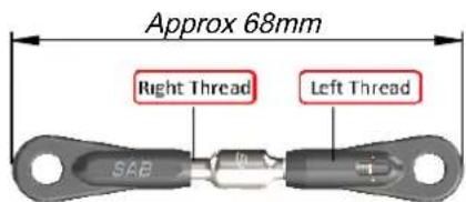
text_image
Approx 68mm Right Thread Left Thread SAB(Initial length for the rods from the swashplate to the Blade Grip.)
text_image
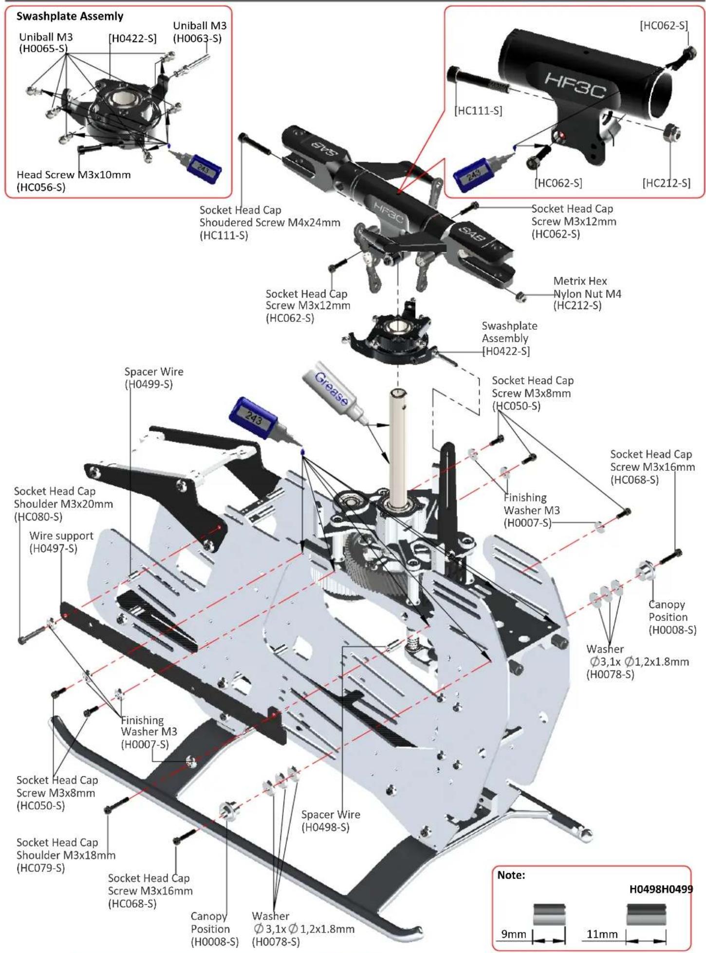
Swashplate Assembly Uniball M3 (H0065-S) [H0422-S] Uniball M3 (H0063-S) Head Screw M3x10mm (HC056-S) Socket Head Cap Shouldered Screw M4x24mm (HC111-S) Socket Head Cap Screw M3x12mm (HC062-S) Swashplate Assembly [H0422-S] Socket Head Cap Screw M3x8mm (HC050-S) Finishing Washer M3 (H0007-S) Socket Head Cap Screw M3x16mm (HC068-S) Wire support (H0497-S) Finishing Washer M3 (H0007-S) Spacer Wire (H0498-S) Spacer Head Cap Screw M3x16mm (HC068-S) Socket Head Cap Shoulder M3x18mm (HC079-S) Socket Head Cap Screw M3x18mm (HC050-S) Canopy Position (H0008-S) Washer Ø3,1x Ø1,2x1.8mm (H0078-S) Spacer Wire (H0498-S) Washer Ø3,1x Ø1,2x1.8mm (H0078-S) GC85S Z43 HF3C HC111-S Z43 HC062-S HC212-S Metrix Hex Nylon Nut M4 (HC212-S) Swashplate Assembly [H0422-S] Socket Head Cap Screw M3x12mm (HC062-S)INSTALLATION OF SWASHPLATE SERVOS
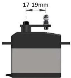
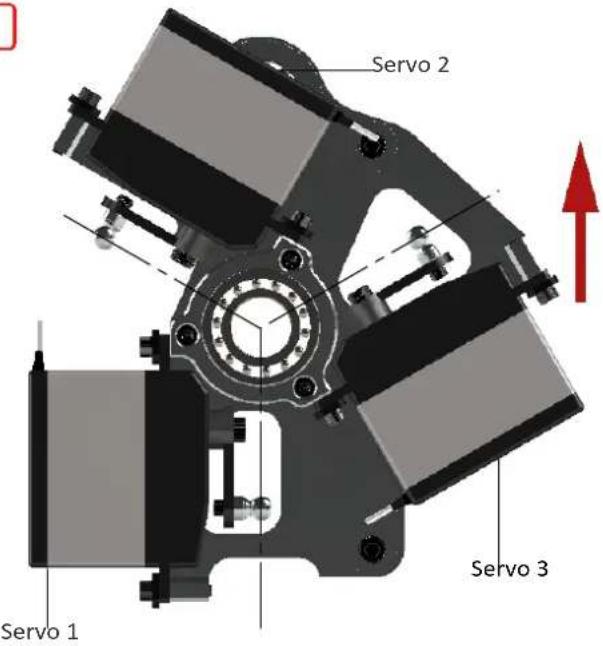
The linkage ball must be positioned between 17-19 mm out on the servo arm (Figure 1), recommended servo arm SAB p/n [HA050/HA051]. The 120° placement of the servos inside Goblin means the arms are difficult to access. For this reason it is advisable to ensure alignment of the servo arms (and sub trim set) before installation of the servos in the model. Proceed with installation following the instructions below. Figure 2 shows a completed installation.
Fig. 1
text_image
17-19mm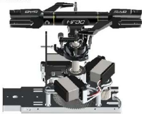
natural_image
Mechanical robotic arm assembly with labeled components (DVO, SAB, HFBC) and no visible text or symbols beyond labelsFig. 2
ASSEMBLY OF THE BALL ON THE HORN
The rods going from the servos to the swash plate must be as vertical as possible. Not all servos are equal, so to better align them you can choose to use the supplied spacer H0031. Figure 3 illustrates this.
Fig. 3
text_image
Servo 2 Servo 3 Servo 1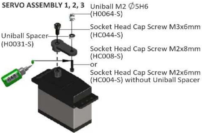
text_image
SERVO ASSEMBLY 1, 2, 3 Uniball M2 Ø5H6 (H0064-S) Socket Head Cap Screw M3x6mm (HC044-S) Uniball Spacer (H0031-S) or Socket Head Cap Screw M2x8mm (HC008-S) Socket Head Cap Screw M2x6mm (HC004-S) without Uniball Spacer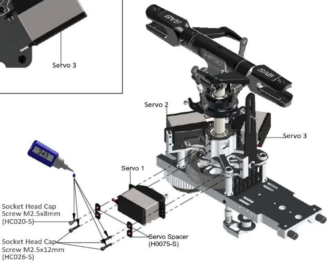
text_image
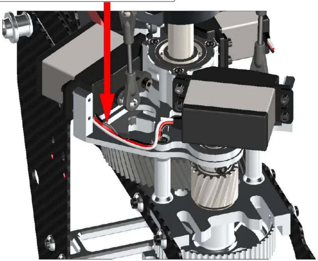
Servo 3 Servo 2 Servo 3 Servo 1 243 Socket Head Cap Screw M2.5x8mm (HC020-S) Socket Head Cap Screw M2.5x12mm (HC026-S) Servo Spacer (H0075-S)The wire for the front servo must be positioned here. Use zip ties.
Fig. 5
natural_image
Mechanical assembly diagram showing gear and motor components with a red arrow indicating a specific part (no text or symbols present)Head HF3C Version Preliminary Setup
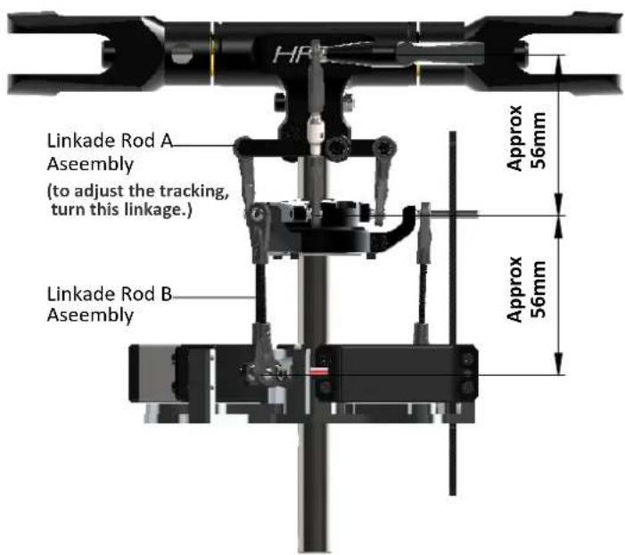
Adjust the linkage as shown. The linkage Rod A has the head right/left. Turning, you can change the tracking without disconnecting the plastic ball link.
text_image
Linkade Rod A Assembly (to adjust the tracking, turn this linkage.) Linkade Rod B Assembly Approx 56mm Approx 56mmLinkage Rod A Assembly ... x2
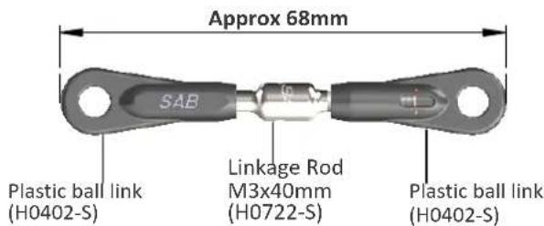
text_image
Approx 68mm SAB Plastic ball link (H0402-S) Linkage Rod M3x40mm (H0722-S) Plastic ball link (H0402-S)Initial length for the rods from the swashplate to the blade grips.
Linkage Rod B Assembly ... x3
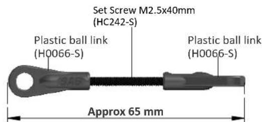
text_image
Set Screw M2.5x40mm (HC242-S) Plastic ball link (H0066-S) Plastic ball link (H0066-S) Approx 65 mmInitial length for the rods from the servos to the swash plate.
TRANSMISSION SETUP
It is important to choose the right reduction ratio to maximize efficiency based on your required flight performance. The Goblin has many possible reduction ratios at your disposal. It is possible to optimize any motor and battery combination. It is recommended to use wiring and connectors appropriate for the currents generated in a helicopter of this class.
If you are using a head speed calculator which requires a main gear and pinion tooth count, use 214 teeth for the main gear (this takes into account the two stage reduction) and the tooth count of your pulley as the pinion count.
Below is a list of available reduction ratios:
| H0126-18-S - 18T | Pinion = ratio 11.9:1 | H0126-22-S - 22T | Pinion = ratio 9.8:1 |
| H0126-19-S - 19T | Pinion = ratio 11.3:1 | H0126-23-S - 23T | Pinion = ratio 9.3:1 |
| H0126-20-S - 20T | Pinion = ratio 10.7:1 | H0126-24-S - 24T | Pinion = ratio 8.9:1 |
| H0126-21-S - 21T | Pinion = ratio 10.2:1 | H0126-25-S - 25T | Pinion = ratio 8.6:1 |
NOTE: If your motor has 6mm motor shaft, you can use the series H0015-xx-S
Some example configurations:
| Battery | Motor | ESC | Pinion | RPM Max | Pitch |
| REV 01 | |||||
| 12S5000/5500 mAh | Kontrionik Pyro 800-480 | Edge 160 HV | 21T - 22T | 1800 rpm1900 rpm | ± 12,5 |
| HobbyWing 160/200KOSMIK 160/200 | 20T - 21T | ||||
| Xnova 4530-500KVQuantum 4530 - 500 | Edge 160 HV | 20T - 21T | |||
| HobbyWing 160/200KOSMIK 160/200 | 19T - 20T | ||||
| Scorpion HK-4526-520KV F3C EditionKDE Direct 700XF - 535 - G3 | Edge 160 HV | 19T - 20T | |||
| HobbyWing 160/200KOSMIK 160/200 | 18T - 19T | ||||
Note: For safety reasons we suggest to not exceed 2000 rpm.
INSTALLATION TAIL SERVO
text_image
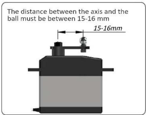
The distance between the axis and the ball must be between 15-16 mm 15-16mm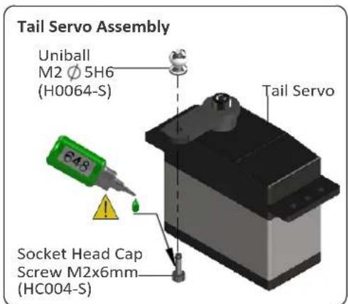
text_image
Tail Servo Assembly Uniball M2 Ø 5H6 (H0064-S) 648 Socket Head Cap Screw M2x6mm (HC004-S) Tail Servo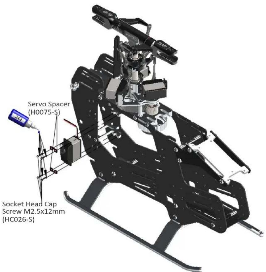
text_image
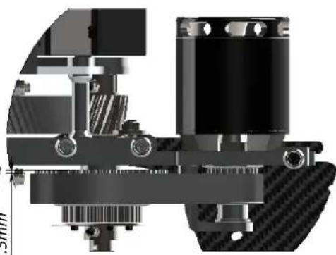
Servo Spacer (H0075-S) Socket Head Cap Screw M2.5x12mm (HC026-S)MOTOR BELT TENSION
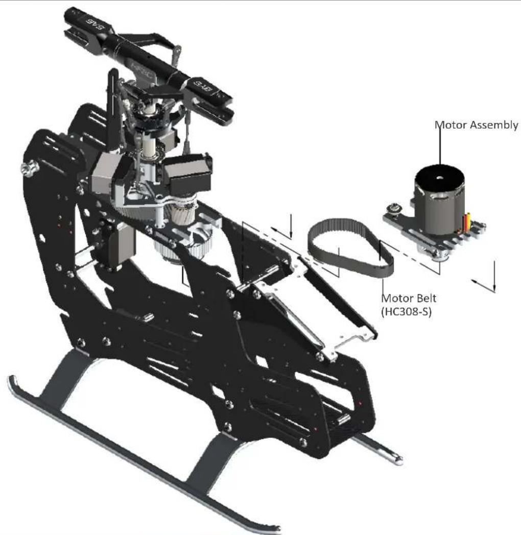
*Assemble the motor and pinion to its mounting plate.
*Fit the motor assembly into position.
*Compress the springs by pushing the motor toward the main shaft.
*At maximum compression, temporarily tighten one of the slide screws.
*With the minimum centre distance it is easy to install the belt. First put the belt on the motor pinion.
*Then put the belt around the big pulley.
*Rotate the motor several times by hand.
*Release the screw that locks the slide.
*The springs keep the belt in tension.
*Help the springs by pulling the motor slightly.
*The belt must be very tight.
*Lock all screws.
text_image
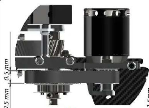
0.5 mm 0.5 mm 1.5mmCorrect
natural_image
Cross-sectional mechanical assembly diagram showing gear and shaft components (no text or labels)Incorrect
Note:
Check for vertical alignment of the motor pulley. To do this, simply turn the motor several time and check to you see if the belt is aligned with the big pulley (one way bearing pulley). If the belt is riding too high, simply loosen up the motor pulley and drop it just a little bit, if it is riding too low, loosen up the motor pulley and raise it a bit.
text_image
Motor Assembly Motor Belt (HC308-S)We recommend de-burring the edges of the carbon parts in areas where electrical wires run. ( See page 4)

ESC INSTALLATION
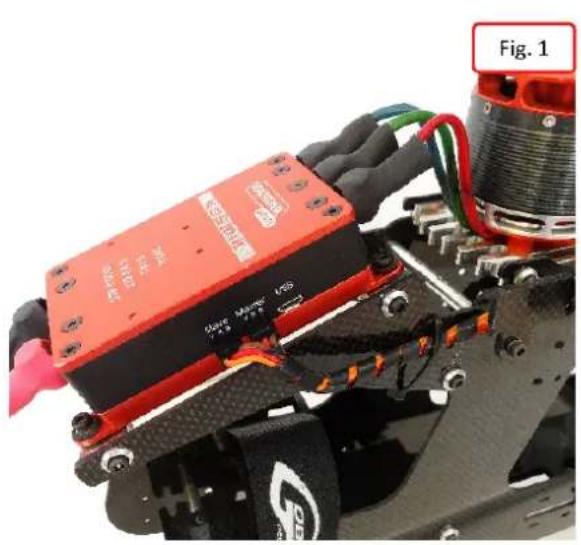
Figure 1: shows the installation of the Kosmik ESC from Kontronik.
Figure 2: Shows the wiring which connects the receiver and ESC. If the BEC used is combined with the ESC, it is recommended to use a dual wire connection and a unit battery backup.
natural_image
Close-up of a red and black robotic device with visible wiring and components, labeled Fig. 1 (no readable text or symbols on the device itself)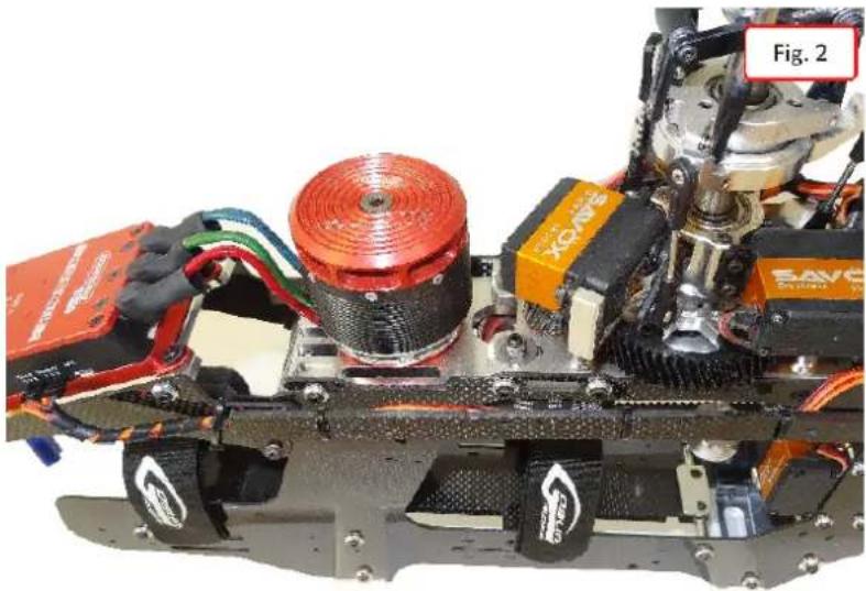
natural_image
Close-up of a mechanical robotic device with visible wiring and components, labeled Fig. 2 (no readable text or symbols on the device itself)Different options for installing the ESC:
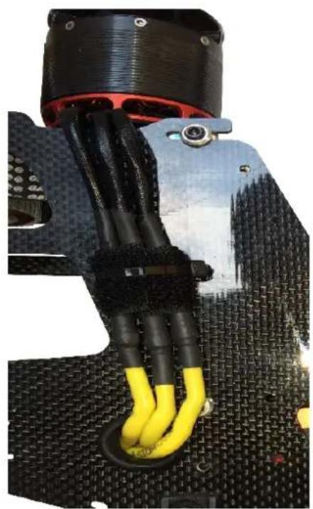
These picture show the ESC installed in the bottom section.
The many positions allow you to find the best personal setup for CG and battery setup. Important, use zip tie to lock the ESC wire to the frame.
natural_image
Close-up of a mechanical assembly with black and yellow wires, no visible text or symbols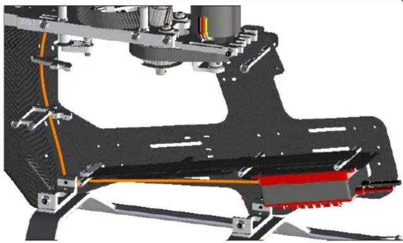
natural_image
3D mechanical assembly diagram showing a robotic arm and mounting bracket (no text or symbols visible)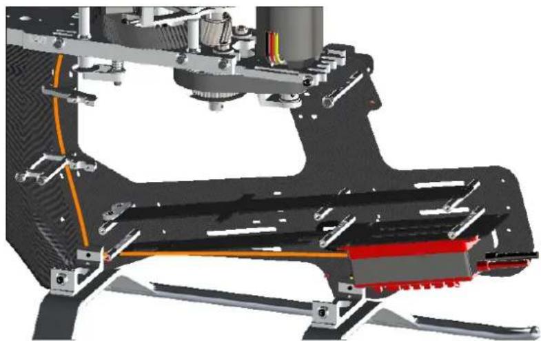
natural_image
3D mechanical assembly diagram showing a robotic arm with grippers and structural components (no text or symbols visible)FLYBARLESS CONTROL UNIT AND RX INSTALLATION
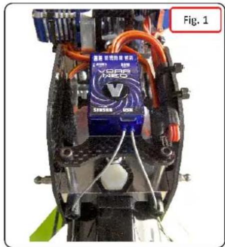
Figures 1 shows an example of installation of the flybarless control unit.
You can use short spacer H0727 (Figure 2).
You can use long spacer H0043 (Figure 3). This is typical if you want to put RX satellite under the control unit.
text_image
Fig. 1 XGAR NASD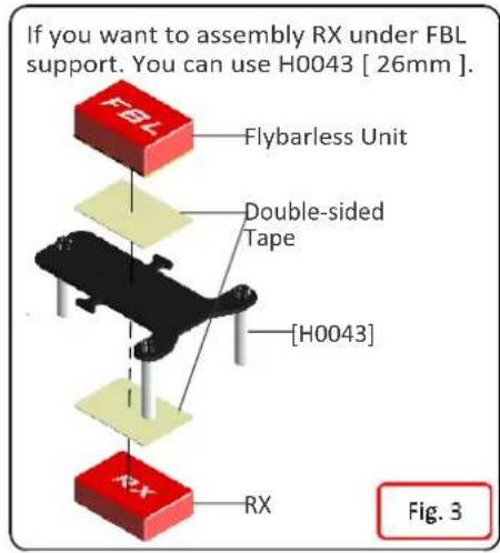
text_image
If you want to assembly RX under FBL support. You can use H0043 [ 26mm ] . Flybarless Unit Double-sided Tape [H0043] RX Fig. 3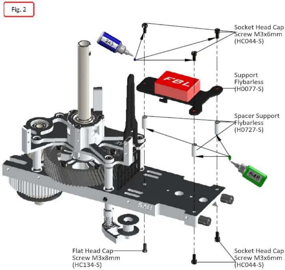
text_image
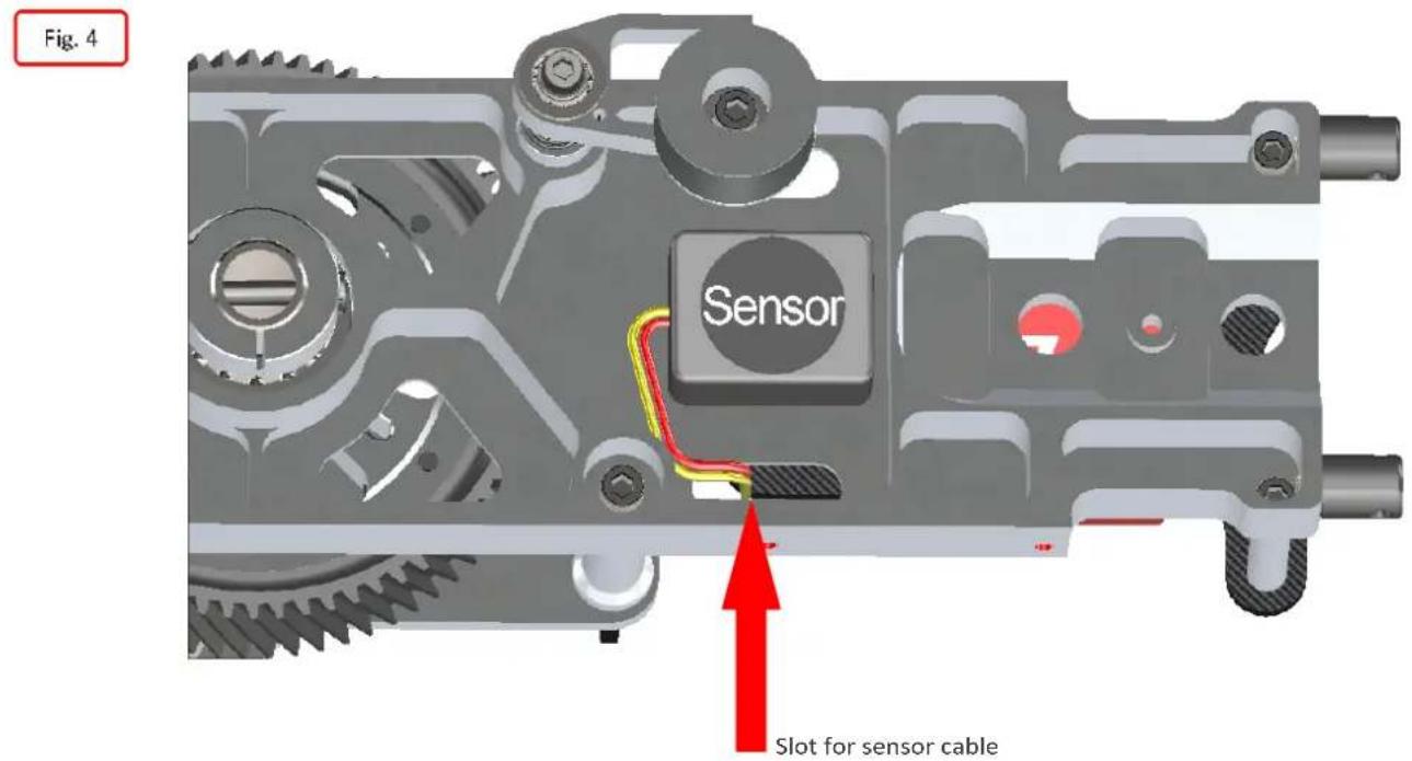
Fig. 2 243 Socket Head Cap Screw M3x6mm (HC044-S) FBL Support Flybarless (H0077-S) Spacer Support Flybarless (H0727-S) 548 SAB Flat Head Cap Screw M3x8mm (HC134-S) Socket Head Cap Screw M3x6mm (HC044-S)For Flybarless systems with a separate sensor, the sensor must be installed under the main plate (Figure 4).
text_image
Fig. 4 Sensor Slot for sensor cableTail Rotor Hub Assembly
text_image
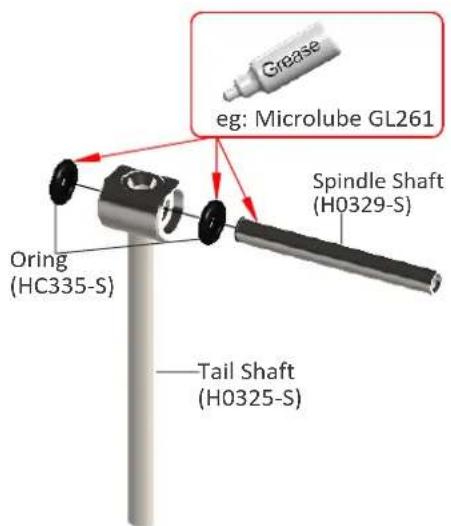
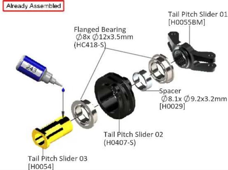
Grease eg: Microlube GL261 Spindle Shaft (H0329-S) Oring (HC335-S) Tail Shaft (H0325-S)Tail Pitch Slider Assembly
text_image
Already Assembled Flanged Bearing Ø8x Ø12x3.5mm (HC418-S) Tail Pitch Slider 01 [H0055BM] Spacer Ø8.1x Ø9.2x3.2mm [H0029] Tail Pitch Slider 02 (H0407-S) Tail Pitch Slider 03 [H0054]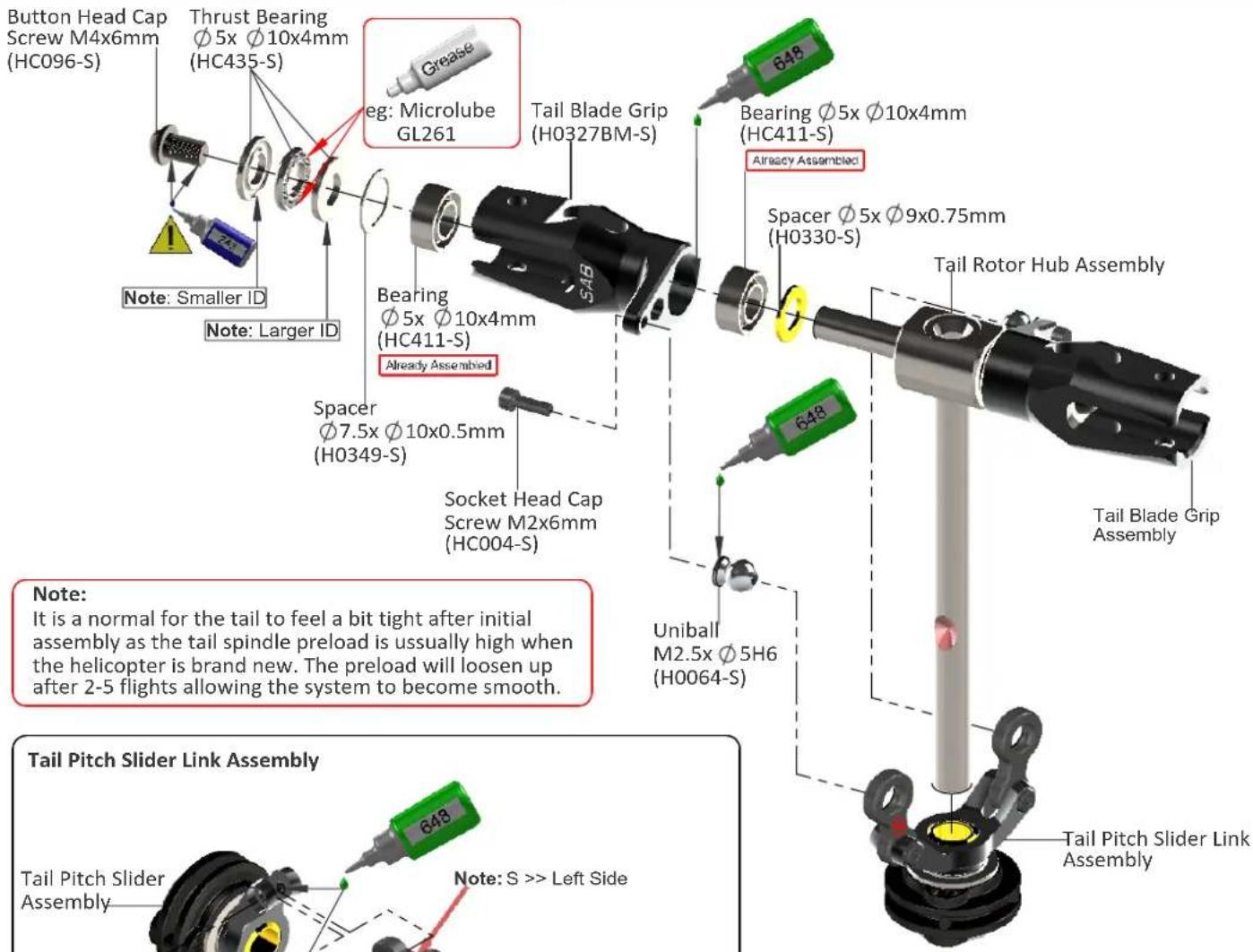
text_image
Button Head Cap Screw M4x6mm (HC096-S) Thrust Bearing Ø 5x Ø10x4mm (HC435-S) eg: Microlube GL261 Tail Blade Grip (H0327BM-S) Bearing Ø5x Ø10x4mm (HC411-S) Already Assembled Spacer Ø 5x Ø9x0.75mm (H0330-S) Tail Rotor Hub Assembly Note: Smaller ID Note: Larger ID Spacer Ø7.5x Ø10x0.5mm (H0349-S) Socket Head Cap Screw M2x6mm (HC004-S) 648 648 Uniball M2.5x Ø5H6 (H0064-S) Tail Blade Grip Assembly Tail Pitch Slider Link Assembly Tail Pitch Slider Assembly 648 Note: S >> Left Side Tail Pitch Slider Link Assembly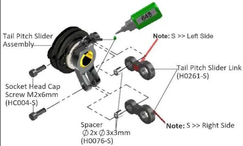
text_image
Tail Pitch Slider Assembly Socket Head Cap Screw M2x6mm (HC004-S) Spacer Ø 2x Ø 3x3mm (H0076-S) 648 Note: S >> Left Side Tail Pitch Slider Link (H0261-S) Note: S >> Right SideBell Crank Lever Assembly
text_image
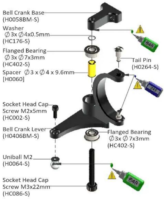
Bell Crank Base (H0058BM-S) Washer Ø 3x Ø4x0.5mm (HC176-S) Flanged Bearing Ø 3x Ø7x3mm (HC402-S) Spacer Ø 3 x Ø 4 x 9.6mm [H0060] Socket Head Cap Screw M2x5mm (HC002-S) Bell Crank Lever (H0406BM-S) Uniball M2 (H0064-S) Socket Head Cap Screw M3x22mm (HC086-S) Flanged Bearing Ø3x Ø7x3mm (HC402-S)Tail Side Plate Assembly
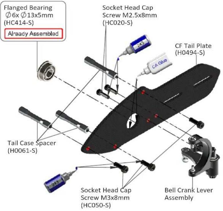
text_image
Flanged Bearing Ø6x Ø13x5mm (HC414-S) Already Assembled Socket Head Cap Screw M2.5x8mm (HC020-S) CF Tail Plate (H0494-S) Tail Case Spacer (H0061-S) 2-13 2-13 Socket Head Cap Screw M3x8mm (HC050-S) Bell Crank Lever AssemblyTail System Assembly
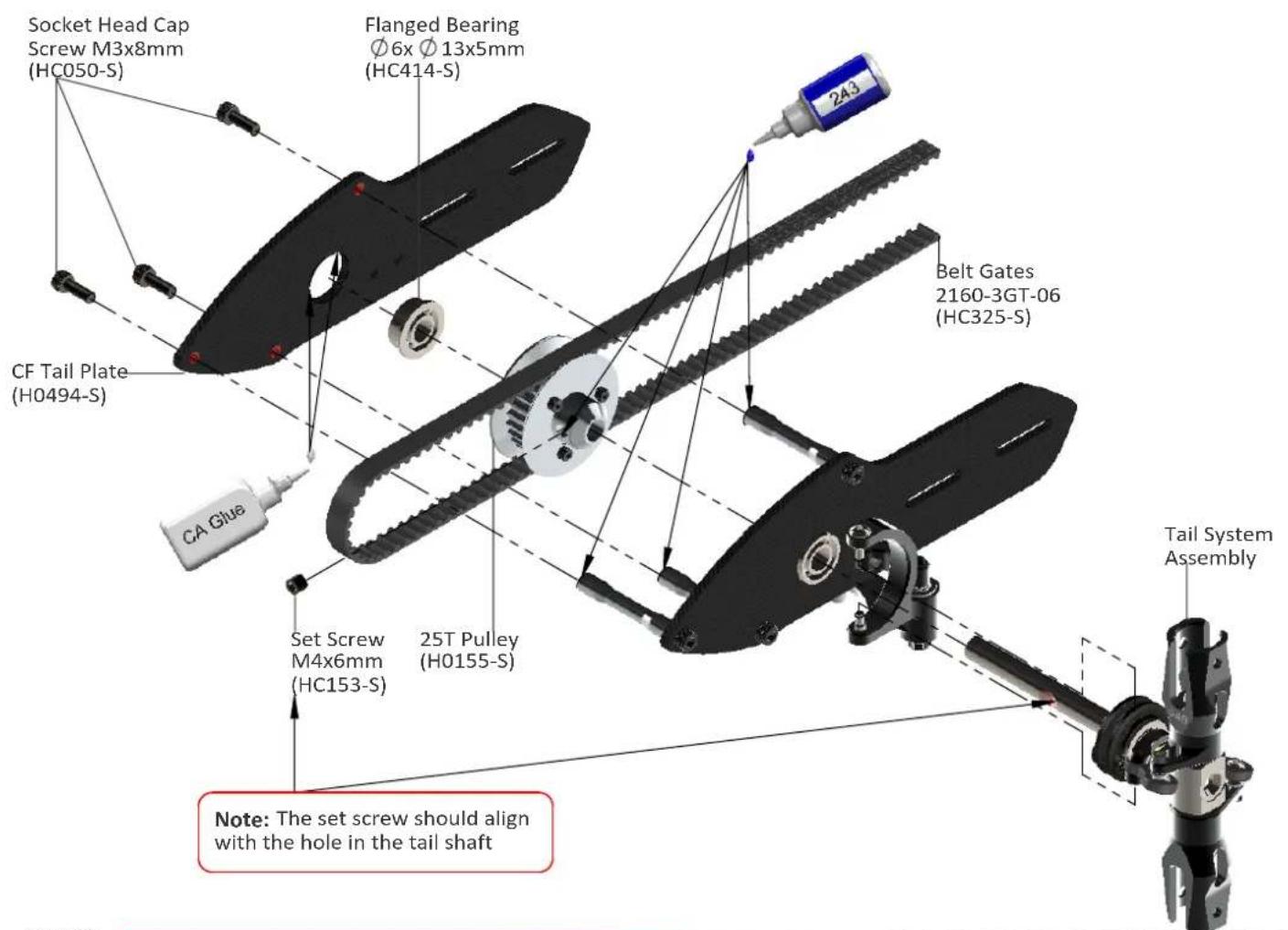
text_image
Socket Head Cap Screw M3x8mm (HC050-S) Flanged Bearing Ø6x Ø13x5mm (HC414-S) CF Tail Plate (H0494-S) CA Glue Set Screw M4x6mm (HC153-S) 25T Pulley (H0155-S) Belt Gates 2160-3GT-06 (HC325-S) Tail System Assembly Note: The set screw should align with the hole in the tail shaftTail Boom Assembly
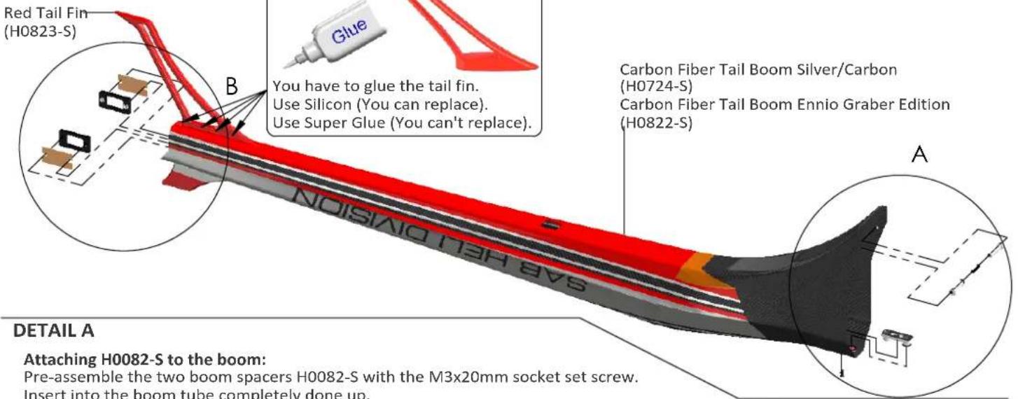
text_image
Red Tail Fin (H0823-S) B You have to glue the tail fin. Use Silicon (You can replace). Use Super Glue (You can't replace). NOISNIO BIDVIS A Carbon Fiber Tail Boom Silver/Carbon (H0724-S) Carbon Fiber Tail Boom Ennio Graber Edition (H0822-S) DETAIL A Attaching H0082-S to the boom: Pre-assemble the two boom spacers H0082-S with the M3x20mm socket set screw. Insert into the boom tube completely done up.DETAIL A
Attaching H0082-S to the boom:
Pre-assemble the two boom spacers H0082-S with the M3x20mm socket set screw.
Insert into the boom tube completely done up.
Center the holes, then unscrew until there is contact with the walls
Lock everything with the adhesive.
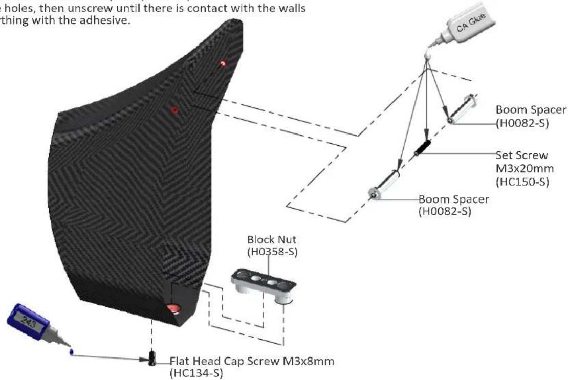
text_image
holes, then unscrew until there is contact with the walls thing with the adhesive. CA Glue Boom Spacer (H0082-S) Set Screw M3x20mm (HC150-S) Boom Spacer (H0082-S) Block Nut (H0358-S) Flat Head Cap Screw M3x8mm (HC134-S)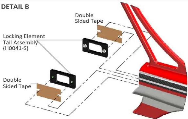
text_image
DETAIL B Double Sided Tape Locking Element Tail Assembly (H0041-S) Double Sided TapeLocking Element Tail Assembly .... X 2
Already Assembled
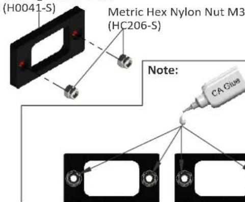
Locking Element Tail
text_image
(H0041-S) Metric Hex Nylon Nut M3 (HC206-S) Note: CA Glue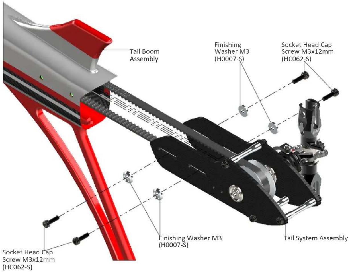
text_image
Tail Boom Assembly Finishing Washer M3 (H0007-S) Socket Head Cap Screw M3x12mm (HC062-S) Finishing Washer M3 (H0007-S) Socket Head Cap Screw M3x12mm (HC062-S) Tail System AssemblyNote: Before put plastic ball in threaded rod, please wait 12 hours after bonding
text_image
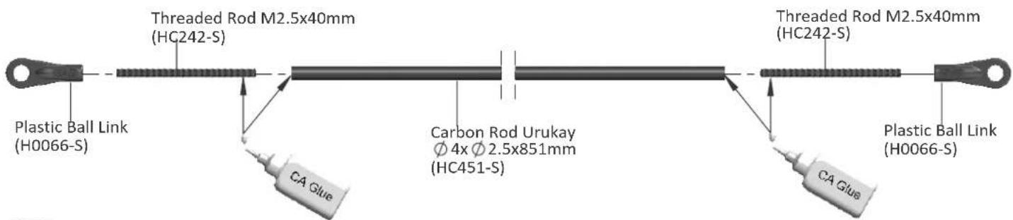
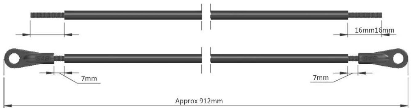
Plastic Ball Link (H0066-S) Threaded Rod M2.5x40mm (HC242-S) Carbon Rod Urukay Ø 4x Ø 2.5x851mm (HC451-S) Threaded Rod M2.5x40mm (HC242-S) Plastic Ball Link (H0066-S)Note:
text_image
16mm16mm 7mm 7mm Approx 912mmNote:
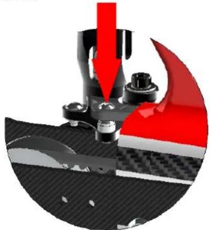
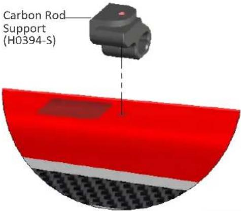
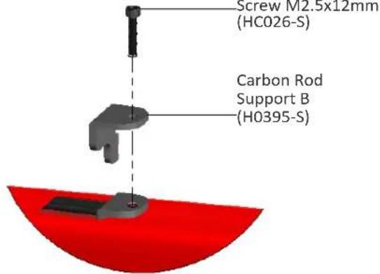
* Install H0394 to the boom.
* Insert carbon rod through the boom making sure it is inserted through H0394.
* Install H0395 making sure to reduce slop (side play) on the carbon rod.
DETAIL A
natural_image
Cross-sectional view of a mechanical assembly with red and black components, no visible text or symbolsDETAIL B
text_image
Carbon Rod Support (H0394-S)
text_image
SARH HEL DIVISION B NOISIAID Tail Boom Assembly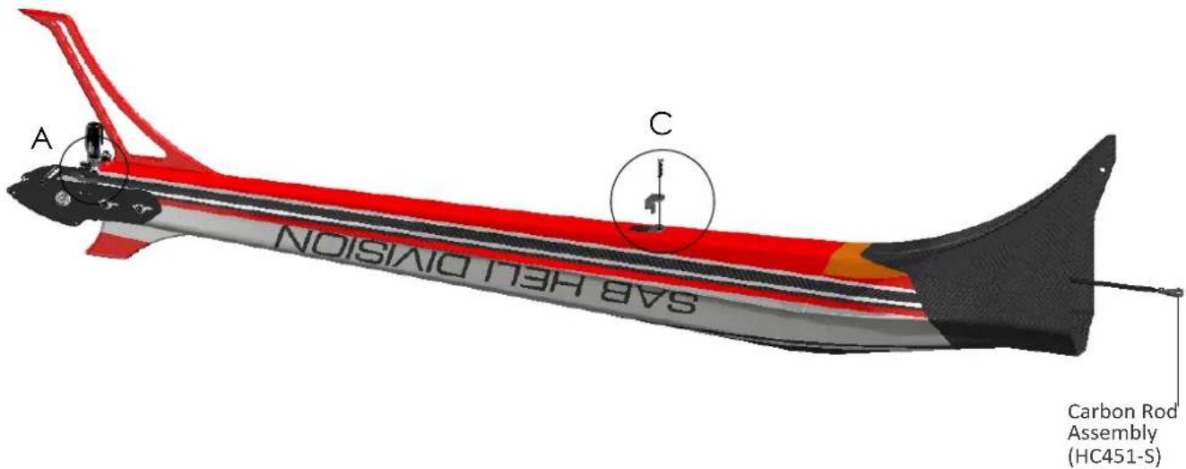
text_image
A C NOISILO DIVISION SAR HEL DIVISION Carbon Rod Assembly (HC451-S)DETAIL C
text_image
Screw M2.5x12mm (HC026-S) Carbon Rod Support B (H0395-S)Note: Lubricate a bit the rod and the H0395 support Lock H0395, doing attention to the maximum smoothness of the carbon rod
BOOM ASSEMBLY
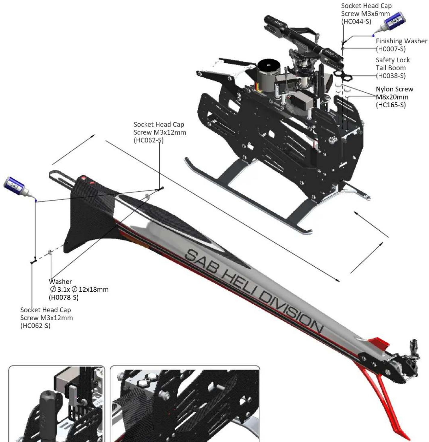
*Insert the tail boom assembly.
*Lock the M8 nuts with the HA016 special tool supplied (Tray 2).
* Firmly lock the lateral screws M3x12. Use Loctile for this screw and make sure you remain tight.
*Assemble the H0038 carbon security plate.
*Connect the Carbon Rod.
text_image
Socket Head Cap Screw M3x6mm (HC044-S) Finishing Washer (H0007-S) Safety Lock Tail Boom (H0038-S) Nylon Screw M8x20mm (HC165-S) Socket Head Cap Screw M3x12mm (HC062-S) SAB HEL DIVISION Washer Ø 3.1x Ø 12x18mm (H0078-S) Socket Head Cap Screw M3x12mm (HC062-S)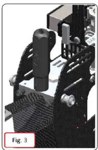
natural_image
Mechanical assembly diagram showing a robotic arm with joints and a textured base, labeled 'Fig. 3' (no readable text or symbols beyond label)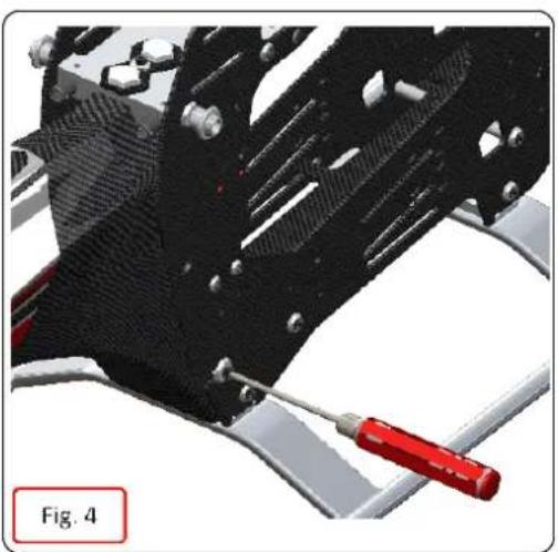
natural_image
Close-up of a mechanical component with red tool and metallic parts, labeled 'Fig. 4' (no readable text or symbols)TAIL BELT TENSION
*Check the proper assembly of the tail boom.
*Check that the aluminum part of the tube is against the M3 stop screw.
*Loosen the tail group by loosening the 4 M3 screws.
*Install the belt onto the pulley, taking care to respect the direction of rotation (figure 1).
*Rotate the tail drive several times by hand.
*Load the spring by a rotation of 270° the tensioning arm (clockwise)
*Tension the boom until the tensioning arm is aligned with the frame.
*Tighten the 4 screws.
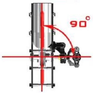
*Check that the tail output shaft is perpendicular to the tube. (figure 2)
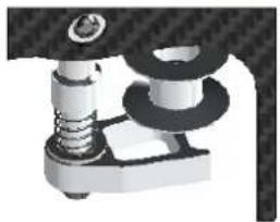
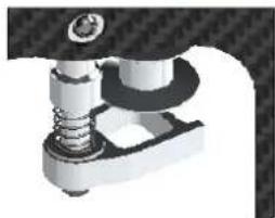
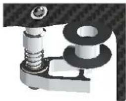
*In figure 3,4,5 you can see the three conditions, ok, too loose and too tight.
NOTE. To disassemble the tail boom it is possible to remove the pulley H0101-S without loosening the tail unit. Remove the locking screw and pull down.
Fig. 2
text_image
90°Fig. 3
natural_image
Mechanical assembly diagram showing a spring-loaded component with mounting base (no text or symbols visible)Fig. 4
natural_image
Mechanical assembly diagram showing a spring-loaded component with a bolt and housing (no text or symbols visible)Fig. 5
natural_image
Mechanical assembly diagram showing spring and bolt components (no text or labels)Fig. 1
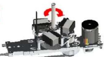
natural_image
Mechanical assembly diagram showing components like gears and a shaft with red motion indicators (no text or labels)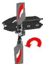
natural_image
Mechanical component diagram with red curved arrows indicating motion or force direction (no text or symbols)CANOPY
The Goblin Urukay canopy has a very effective locking system in order to eliminate vibrations and optimize aerodynamics.
You must install the following to complete the canopy assembly:
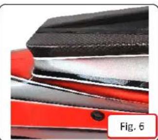
· Canopy grommets (Fig 6), Canopy edge protection Fig 7 and Fig 8.
The canopy hole must be 12 to 12.5 mm in diameter. Initially is 9 mm. You can enlarge the hole slightly to optimize the vertical position of the canopy itself.
To install the canopy:
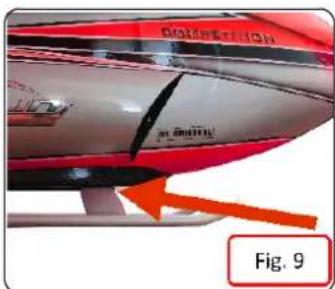
- Insert the canopy from the front up to the area of the block shown in Fig. 9
· Join the edges. - Insert the H0036 knobs.
natural_image
Close-up of layered metal components with red and black surfaces, labeled Fig. 6 (no text or symbols on the main subject)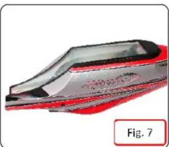
natural_image
Close-up of a red and black plastic object with a label 'Fig. 7' (no other text or symbols visible)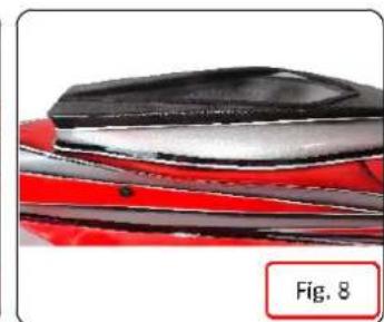
natural_image
Close-up of a car's roof and roof tiles with red and black bands, labeled Fig. 8 (no text or symbols on the tile itself)
Knoobs [H0036]
text_image
DINNATION Fig. 9BATTERIES
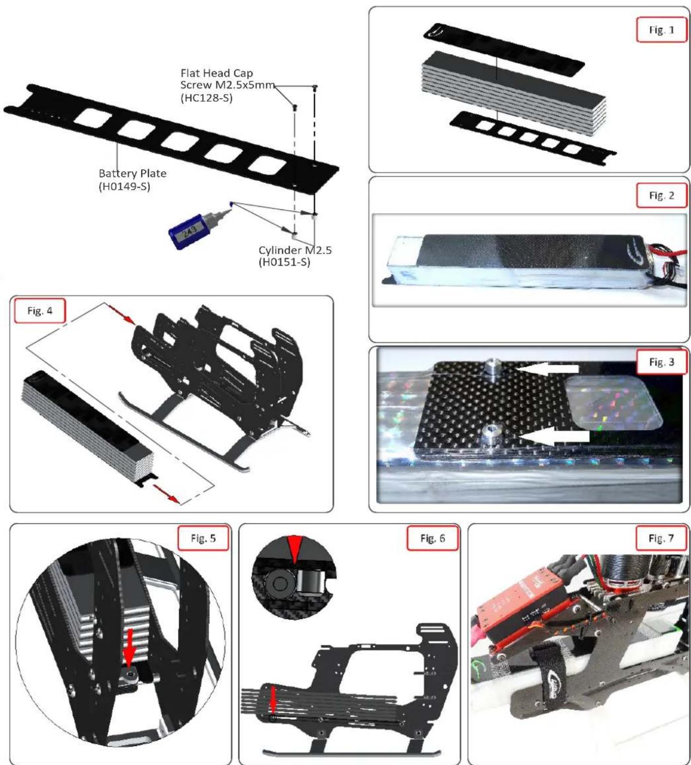
The battery tray system in the Goblin URUKAY is simple, but very effective.
The battery should be attached to the tray (Part H0149) with heat shrink, tape or velcro.
You can optionally use the battery protection tray (Part H0151) see Fig. 1, 2.
Before permanently mounting the batteries onto the battery tray, check the ideal position for the best center of gravity.
Cut the heat shrink around the carbon fiber tray locking pins. Fig. 3.
Battery Pack:
Slide the tray until it locks into the CNC stopper. Fig. 4, 5.
Using the velcro straps, making sure that the two locking pins are stopped against the frame spacer
(P/n #H0003 and #H0151) Fig.6, 7.
OPERATIONS BEFORE FLIGHT
*Set up the remote control and the flybarless system with utmost care.
*It is advisable to test the correct settings of the remote and flybarless system without main blades and tail blades fitted.
*Check that all wiring is isolated from the carbon/aluminum parts. It is good practice to protect them at the points where they are at most risk.

*Be sure of the gear ratio, verifying carefully the motor pulley in use. The forces acting on the mechanics increase enormously with increasing of rpm. For safety reasons we suggest to not exceed 2000 rpm.
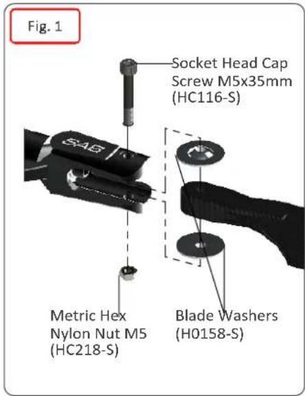
*Fit the main blades and tail blades. (Fig.1 and Fig.2)
*Please make sure the main blades are tight on the blade grips. Failure to tighten the blades properly can result in a boom strike. To fold the blades for storage, it is advisable to loosen them.
*Check the collective and cyclic pitch.
*It is important to check the correct tracking of the main blades.
*On the Goblin, in order to correct the tracking, adjust the main link rod as shown in figure 3. This is provided with a right/left thread system that allows continuous fine adjustments of the length of the control rod; for this adjustment it is not necessary to detach the ball link.

*Perform the first flight at a low headspeed, 1500/1600 RPM. After this first flight, do a general check of the helicopter. Verify that all screws are correctly tightened.
text_image
Fig. 1 Socket Head Cap Screw M5x35mm (HC116-S) Metric Hex Nylon Nut M5 (HC218-S) Blade Washers (H0158-S)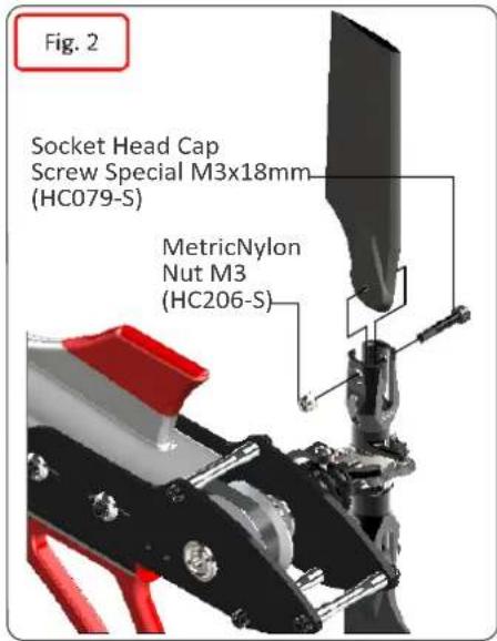
text_image
Fig. 2 Socket Head Cap Screw Special M3x18mm (HC079-S) MetricNylon Nut M3 (HC206-S)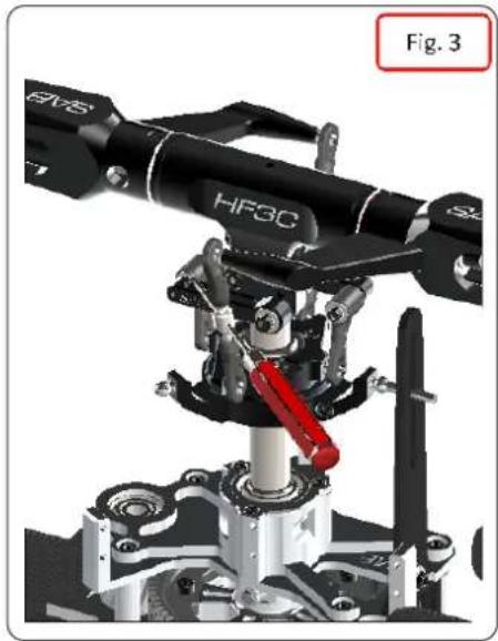
natural_image
Mechanical robotic arm assembly with labeled components (HF3C, S2) and a red lever mechanism, no readable text or symbols beyond labels.IN FLIGHT
For hovering, it is recommended a headspeed of 1400-1500 rpm For normal flight, it is recommended a headspeed of 1900 rpm
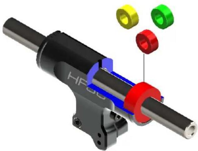
It is possible change the rigidity of the dampening system. In the Kit, you can find Damper H0482-80:80 Shore (Red). You can change H0482-70 (Yellow), H0482-90 (Green), for change the head characteristic.
Changing the Damper, please check the Axial preload. The blade grips must move freely, but they should not move just under their own weight. You can remove / add the 0.2mm shim (HC232) from each side for to get perfect preload.
It is possible change the main rotor/tail rotor ratio In the Kit the tail pulley is 25T and the ratio is 5.3
Here the different option:
[H0102-S] 27T, ratio 4.9
[H0103-S] 26T, ratio 5.1
[H0154-S] 24T, ratio 5.5
natural_image
3D mechanical assembly diagram showing a shaft with red and blue components and three colored parts (yellow, green, red) attached to the shaft (no text or symbols present)MAINTENANCE
*On the Goblin, areas to look for wear include:
* Motor belt
* Tail belt
* Damper
* Main gear and pinion
The lifespan of these components varies according to the type of flying. On average it is recommended to replace these special parts every 100 flights.
*The head tends to lose rigidity after a while. Check this condition every 20 flights. Preloading with precision shim washers, it is possible to vary the rigidity of the head.
*Check all uniballs often.
*The most stressed bearings are definitely those of the tail shaft. Check them frequently. All other parts are not particularly subject to wear.
*Periodically lubricate the tail slide movement and its linkages as well as the swashplate movement and its linkages.
* Lubricate the main gear with proper Lubricant every 20 flights.
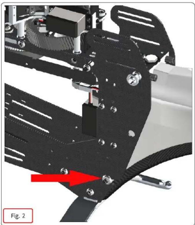
*Check the screws that are highlighted in the following images frequently, make sure you remain tight (fig.2 and fig.3).
*To ensure safety you should do a general inspection of the helicopter after each flight. You should check:
* The maintenance of proper belt tension.
* The proper isolation of wires from the carbon and aluminum parts.
* That all screws remain tight.
natural_image
Mechanical assembly diagram showing a robotic arm with red arrow indicating motion direction (no text or symbols)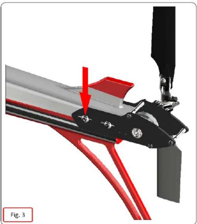
natural_image
Mechanical assembly diagram showing red and black components with a red arrow indicating a specific part (no text or symbols present)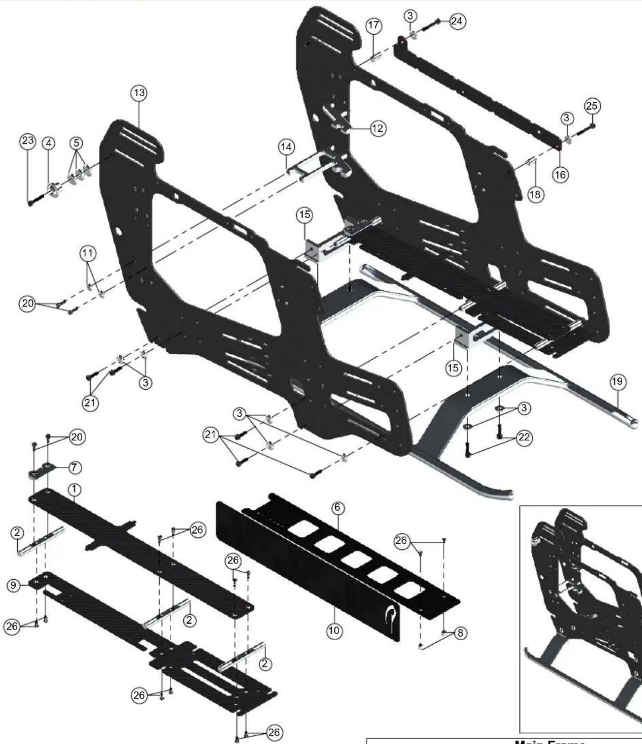
text_image
Technical diagram of a vehicle chassis with numbered components and structural annotations
natural_image
Mechanical component with black frame structure and mounting base (no text or symbols visible)| Main Frame | ||||
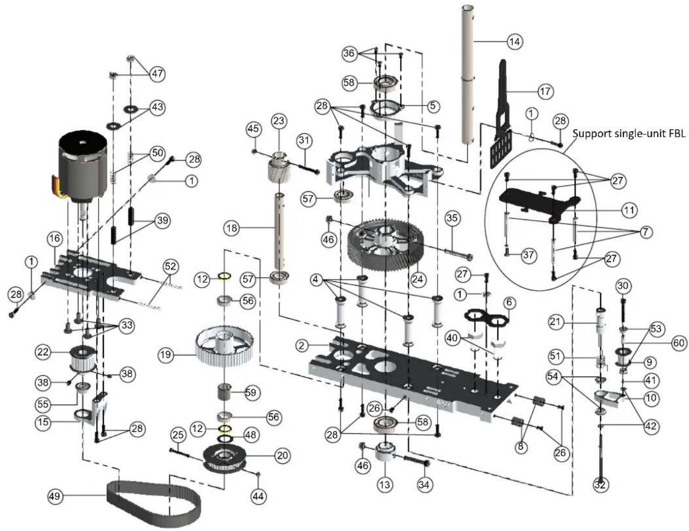
| POS | COD | Name | Specification | Quantity |
| 1 | H0002 | Battery Tray Carbon Fiber | 1 | |
| 2 | H0003 | Frame Spacers | Aluminum | 3 |
| 3 | H0007 | Finishing Washers M3 | Aluminum | 20 |
| 4 | H0008 | Canopy Poitioner | Aluminum | 2 |
| 5 | H0078 | Washer 3,1x 1,2x1.8 | Aluminum | 6 |
| 6 | H0149 | Battery Plate | Carbon Fiber | 1 |
| 7 | H0150 | Stop Battery Plate | Aluminum | 1 |
| 8 | H0151 | Cylinder M2.5 | Aluminum | 2 |
| 9 | H0153 | Battery Support | Carbon Fiber | 1 |
| 10 | H0153-1 | Battery Protection | Carbon Fiber | 1 |
| 11 | H0255 | Finishing Washers M2.5 | Aluminum | 6 |
| 12 | H0436 | Tail Servo Support | Aluminum | 1 |
| 13 | H0824 | Main Frames | Carbon Fiber | 2 |
Main Frame
| POS | COD | Name | Specification | Quantity |
| 14 | H0495 | Tail Servo Support | Aluminum | 1 |
| 15 | H0496 | Landing Gear Support | Aluminum | 2 |
| 16 | H0497 | Wire Supports | Carbon Fiber | 1 |
| 17 | H0498 | Spacer Wire 11mm | Aluminum | 1 |
| 18 | H0499 | Spacer Wire 9mm | Aluminum | 1 |
| 19 | H0725 | Landing Gear Silver | 1 | |
| H0639 | Landing Gear White | |||
| 20 | HC020 | Socket Head Cap Screws | M2.5 x 8mm | 8 |
| 21 | HC056 | Socket Head Cap Screws | M3 x 10mm | 16 |
| 22 | HC062 | Socket Head Cap Screws | M3 x 12mm | 4 |
| 23 | HC068 | Socket Head Cap Screws | M3 x 16mm | 2 |
| 24 | HC079 | Head Cap Shoulder | M3x18mm | 1 |
| 25 | HC080 | Head Cap Shoulder | M3x20mm | 1 |
| 26 | HC128 | Flat Head Cap Screws | M2.5 x 5mm | 12 |
text_image
Support single-unit FBL 14 17 28 36 58 28 50 28 1 39 45 23 31 57 46 35 18 12 52 57 4 27 1 6 30 21 53 60 27 11 7 37 27 16 12 56 19 33 22 38 55 15 28 12 59 56 25 48 20 44 46 13 34 8 26 42 32 49TRANSMISSION ASSEMBLY
| POS | COD | Name | Specification | Quantity |
| 1 | H0007 | Finishing Washers M3 | Aluminum | 4 |
| 2 | H0009 | Main Structure | Aluminum | 1 |
| 3 | H0010 | Servo Support | Aluminum | 1 |
| 4 | H0018 | Columns | Aluminum | 4 |
| 5 | H0024 | Main Shaft Bearing Support | 1 | |
| 6 | H0038 | Safety Locking Tail Boom | Carbon Fiber | 1 |
| 7 | H0043 | Spacers Flybarless | 3 | |
| 8 | H0050 | Antenna Guide | Plastic | 2 |
| 9 | H0834 | Tail Belt Idler | 1 | |
| 10 | H0071 | Belt Tensioner Arm | 1 | |
| 11 | H0077 | Flybarless Support | Carbon Fiber | 1 |
| 12 | H0110 | Bush-One Ways | 10 × 13 × 1.4mm | 2 |
| 13 | H0121 | M4 Locking Collar | 1 | |
| 14 | H0127 | Main Shaft | 1 | |
| 15 | H0142 | Support Bearing | Aluminum | 1 |
| 16 | H0143 | Motor Support | Aluminum | 1 |
| 17 | H0152 | Swash plate Anti-Rotation Guide | Carbon Fiber | 1 |
| 18 | H0157 | Secondary Shaft | 1 | |
| 19 | H0104 | One Way Double Bearing | 60T | 1 |
| 20 | H0101 | Front Tail Pulley Low | 37T | 1 |
| 21 | H0070 | Column Bell Tensioner | 1 | |
| 22 | H0126-20 | Motor Pulley 20mm | 20T | 1 |
| 23 | H0156 | Drive Pinion | 19T M1 | 1 |
| 24 | H0405 | Main Gear | 68T M1 | 1 |
| 25 | HC033 | Socket Head Cap Screw Shouldereds | M2.5 x 19mm | 1 |
| 26 | HC038 | Button Head Cap Screws | M3 x 4mm | 3 |
| 27 | HC044 | Socket Head Cap Screws | M3 x 6mm | 6 |
| 28 | HC050 | Socket Head Cap Screws | M3 x 8mm | 4 |
| 29 | HC056 | Socket Head Cap Screws | M3 x 10mm | 9 |
| 30 | HC080 | Socket Head Cap Screw | M3 x 20mm | 1 |
| 31 | HC079 | Socket Head Cap Screw | M3 x 18mm | 1 |
TRANSMISSION ASSEMBLY
| POS | COD | Name | Specification | Quantity |
| 32 | HC092 | Socket Head Cap Shoudered | m3 x 50mm | 1 |
| 33 | HC098 | Button Head Cap Screws | M4 x 8mm | 4 |
| 34 | HC104 | Socket Head Cap Screw | M4 x 22mm | 1 |
| 35 | HC111 | Socket Head Cap Screw | M4 x 24mm | 1 |
| 36 | HC128 | Flat Head Cap Screws | M2.5 x 5mm | 3 |
| 37 | HC134 | Flat Head Cap Screw | M3 x 8mm | 1 |
| 38 | HC153 | Set Screws | M4 x 6mm | 1 |
| 39 | HC158 | Set Screws | M5 x 20mm | 2 |
| 40 | HC165 | Vite Nylon Esa | M8 x 20mm | 2 |
| 41 | HC176 | Washer | 3 × 4 × 0.5 mm | 1 |
| 42 | HC180 | Washers | 3.2 × 6 × 0.5 mm | 2 |
| 43 | HC188 | Washers | 5.3 × 15 × 1 mm | 2 |
| 44 | HC200 | Metric Hex Nylon Nuts | M2.5 H3.5mm | 1 |
| 45 | HC206 | Metric Hex Nylon Nuts | M3 H4mm | 1 |
| 46 | HC212 | Metric Hex Nylon Nuts | M4 H5mm | 2 |
| 47 | HC218 | Metric Hex Nylon Nuts | M5 H4.8mm | 2 |
| 48 | HC232 | Washer | 10 × 16 × 0.2 mm | 1 |
| 49 | HC308 | Big Motor Belt | 240-3MGT | 1 |
| 50 | HC310 | Springs | De 5.8-df0.3-LL9 | 2 |
| 51 | HC312 | Spring | De 8-df0.5-LL8 | 1 |
| 52 | HC315 | Springs | De 8-df0.5-LL12 | 2 |
| 53 | HC402 | Flanged Bearings | 3 × 7 × 3 mm | 2 |
| 54 | HC410 | Flanged Bearings | 5 × 9 × 3 mm | 2 |
| 55 | HC414 | Flanged Bearings | 6 × 13 × 5 mm | 1 |
| 56 | HC420 | Bearings | 10 × 15 × 4 mm | 2 |
| 57 | HC422 | Bearings | 10 × 19 × 5 mm | 2 |
| 58 | HC426 | Bearings | 12 × 24 × 6 mm | 2 |
| 59 | HC442 | One Way Bearing | 10 × 14 × 12 mm | 2 |
| 60 | H0060 | Bushing | 1 |
text_image
HF3C SAB Servo Assembly 1, 2, 3 Head System| Head System | ||||
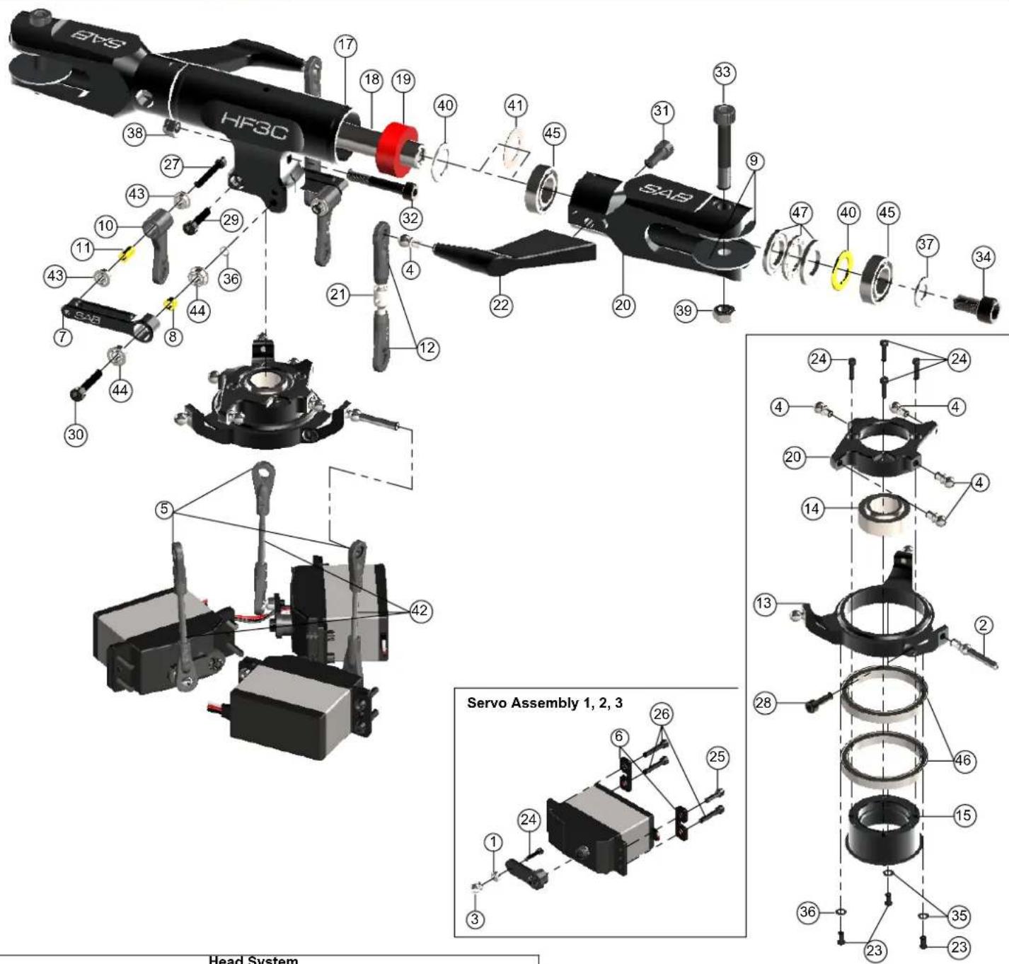
| Pos | Code | Name | Specification | Quantity |
| 1 | H0031 | Uniball Spacers | Aluminum | 3 |
| 2 | H0063 | Uniballs | M3x4 5 H18 | 1 |
| 3 | H0064 | Uniballs | M2.5 5 H6 | 3 |
| 4 | H0065 | Uniball M3 | Steel | 8 |
| 5 | H0066 | Plastic Ball Linkages | Plastic | 6 |
| 6 | H0075 | Servo Spacers | Carbon Fiber | 6 |
| 7 | H0132BM | Radius Arm | Aluminum Black Matte | 2 |
| 8 | H0134 | Spacer Arm | 2 | |
| 9 | H0158 | Blade Washers | Aluminum | 4 |
| 10 | H0205 | Uniball Radius Arm | Plastic | 2 |
| 11 | H0253 | Spacer Arm | 2 | |
| 12 | H0402 | Uniball M3 | Plastic | 4 |
| 13 | H0420-01BM | Swashplate 01 | Aluminum Black Matte | 1 |
| 14 | H0420-03 | Swashplate 03 | Steel | 1 |
| 15 | H0420-04BM | Swashplate 04 | Aluminum Black Matte | 1 |
| 16 | H0422-02BM | Swashplate 02 | Aluminum Black Matte | 1 |
| 17 | H0479BM | Center Hub | Aluminum Black Matte | 1 |
| 18 | H0481 | Spindle | Steel | 1 |
| 19 | H0482-80 | Damper | Red 80 shore | 2 |
| 20 | H0719BM | Main Blade Grip | Aluminum Black Matte | 2 |
| 21 | H0722 | Main Linkages Steel | 2 | |
| 22 | H0817BM | Blade Grip Arm | Aluminum Black Matte | 2 |
| 23 | HC005 | Button Cap Screws | M2x5mm | 3 |
| 24 | HC008 | Head Cap Screws | M2 x 8mm | 7 |
| Head System | ||||
| Pos | Code | Name | Specification | Quantity |
| 25 | HC020 | Head Cap Screws | M2.5x10mm | 3 |
| 26 | HC026 | Head Cap Screws | M2.5x12mm | 9 |
| 27 | HC032 | Head Cap Screws | M2.5x18mm | 2 |
| 28 | HC056 | Head Cap Screws | M3x10mm | 1 |
| 29 | HC062 | Head Cap Screws | M3x12mm | 2 |
| 30 | HC068 | Head Cap Screws | M3x16mm | 2 |
| 31 | HC102 | Head Cap Screws | M4x10mm | 2 |
| 32 | HC111 | Head Cap Shoulder | M4x24mm | 1 |
| 33 | HC114 | Head Cap Shoulder | M5x30mm | 2 |
| 34 | HC124 | Head Cap Screws | M6x10mm | 2 |
| 35 | HC170 | Washers | 2 × 5 × 0.5 mm | 3 |
| 36 | HC176 | Washers | 3 × 4 × 0.5 | 2 |
| 37 | HC194 | Washers | 6 × 14 × 1 | 2 |
| 38 | HC212 | Nylon Nut | M4 | 1 |
| 39 | HC218 | Nylon Nut | M5 | 2 |
| 40 | HC230 | Washers | 10 × 16 × 1 mm | 4 |
| 41 | HC232 | Washers | 10 × 16 × 0.2 mm | 2 |
| 42 | HC242 | threaded rods | M2.5 x 40mm | 3 |
| 43 | HC400 | Flanged Bearing | 2.5 × 6 × 2.5 mm | 4 |
| 44 | HC402 | Flanged Bearing | 3 × 7 × 3 mm | 4 |
| 45 | HC422 | Bearing | 10 × 19 × 5 mm | 4 |
| 46 | HC430 | Bearing Rads | 30 × 37 × 4 mm | 2 |
| 47 | HC438 | Thrust Bearing | 10 × 18 × 5.5 mm | 2 |
text_image
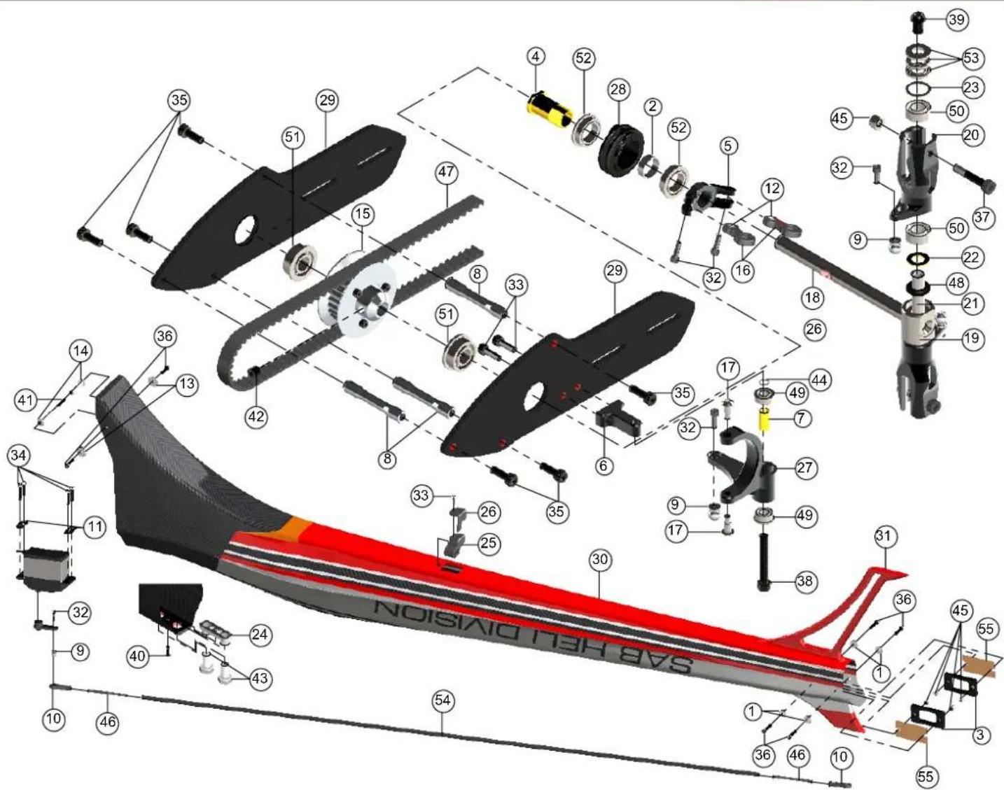
SAB NEU DIVISION NOISI DI VISION| POS | COD | Name | Specification | Quantity |
| 1 | H0007 | Finishing Washer M3 | Aluminum | 4 |
| 2 | H0029 | Spacer | 8.1 × 9.2 × 3.2mm | 1 |
| 3 | H0041 | Locking Element Tails | Carbon Fiber | 2 |
| 4 | H0054 | Tail Pitch Slider 02 | Aluminum | 1 |
| 5 | H0055BM | Tail Pitch Slider 01 | Aluminum | 1 |
| 6 | H0058BM | Bell Crank Base | Aluminum | 1 |
| 7 | H0060 | Spacer | 3 × 4 × 9.6mm | 1 |
| 8 | H0061 | Tail Case Spacers | Aluminum | 3 |
| 9 | H0064 | Uniballs | M2.5 5H6 | 4 |
| 10 | H0066 | Plastic Ball Links | Plastic | 2 |
| 11 | H0075 | Servo Spacer | Carbon Fiber | 2 |
| 12 | H0076 | Grip Link Bush | Aluminum | 2 |
| 13 | H0078 | Washers | 3.1 × 12 × 1.8mm | 2 |
| 14 | H0082 | Boom spacers | Aluminum | 2 |
| 15 | H0155 | Tail Pulley | 25T | 1 |
| 16 | H0261 | Tail Pitch Slider Link | Aluminum | 2 |
| 17 | H0264 | Tail Pin | 2 | |
| 18 | H0325 | Tail Shaft | 1 | |
| 19 | H0326 | Tail Hub | 1 | |
| 20 | H0327BM | Tail Blade Grip | 2 | |
| 21 | H0329 | Tail Spindle | 1 | |
| 22 | H0330 | Washer | 5x 9x0.75mm | 2 |
| 23 | H0349 | Washer | 7.5x 10x0.5mm | 2 |
| 24 | H0358 | Block Nut | 1 | |
| 25 | H0394 | Carbon Rod Support | 1 | |
| 26 | H0395 | Carbon Rod Support B | 1 | |
| 27 | H0406BM | Bell Crank Lever | Aluminum | 1 |
| 28 | H0407 | Tail Pitch Slider 02 | Black Derlin | 1 |
| TAIL SYSTEMTAIL SYSTEM | ||||
| POS | COD | Name | Specification | Quantity |
| 29 | H0494 | Carbon Tail Side Plate | Carbon Fiber | 2 |
| 30 | H0822 | Tail Boom Ennio Edition | 1 | |
| H0724 | Tail Boom Silver | |||
| 31 | H0823 | Red Tail Fin | 1 | |
| 32 | HC004 | Socket Head Cap Screws | M2 x 6mm | 6 |
| 33 | HC020 | Socket Head Cap Screws | M2.5 x 8mm | 3 |
| 34 | HC026 | Socket Head Cap Screws | M2.5 x 12mm | 4 |
| 35 | HC050 | Socket Head Cap Screws | M3 x 8mm | 6 |
| 36 | HC062 | Socket Head Cap Screws | M3 x 12mm | 6 |
| 37 | HC079 | Socket Head Cap Shoudered | M3 x 18mm | 2 |
| 38 | HC086 | Socket Head Cap Screws | M3 x 22mm | 1 |
| 39 | HC096 | Button Head Cap Screws | M4 x 6mm | 2 |
| 40 | HC134 | Flat Head Cap Screws | M3x8mm | 1 |
| 41 | HC150 | Set Screws | M3 x 20mm | 1 |
| 42 | HC153 | Set Screws | M4 x 6mm | 1 |
| 43 | HC165 | Nylon Screw | M8x20mm | 2 |
| 44 | HC176 | Washer | 1 | |
| 45 | HC206 | Metric Hex Nylon Nuts | M3 | 6 |
| 46 | HC242 | Threaded Rods | M2.5 x 40mm | 2 |
| 47 | HC325 | Belt Gates | 1 | |
| 48 | HC335 | Oring | 2 | |
| 49 | HC402 | Flanged Bearings | 3 × 7 × 3mm | 2 |
| 50 | HC411 | Bearings | 5x 10x4mm | 4 |
| 51 | HC414 | Flanged Bearings | 6 × 13 × 5mm | 2 |
| 52 | HC418 | Flanged Bearings | 8 × 12 × 3.5mm | 2 |
| 53 | HC435 | Thrust Bearings | 5x 10x4mm | 2 |
| 54 | HC451 | Carbon Rod | 1 | |
| 55 HA015 | Double-Sided Tapes | 2 | ||
| Battery Tray[H0002-S] | Frame Spacer[H0003-S] | Finishing Washer M3[H0007-S] | Canopy Positioner[H0008-S] | Main Structure[H0009-S] |
 - 1 x CF Battery Tray.- 6 x Flat Head Cap ScrewsM2.5x5mm. - 1 x CF Battery Tray.- 6 x Flat Head Cap ScrewsM2.5x5mm. | 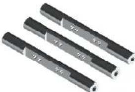 - 3 x Frame Spacers. - 3 x Frame Spacers. |  - 10 x Finishing Washers . - 10 x Finishing Washers . | 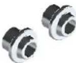 - 2 x Canopy Positioner . - 2 x Canopy Positioner . | 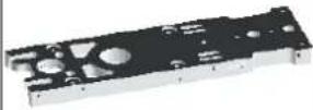 - 1 x Main Structure. - 1 x Main Structure. |
Servo Support[H0010-S]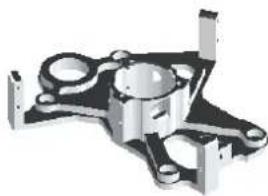 - 1 x Servo Support. - 1 x Servo Support. | Column[H0018-S]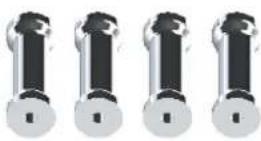 - 4 x Columns. - 4 x Columns. | Bearing Support[H0024-S]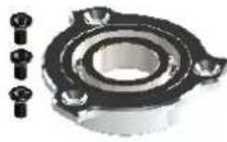 - 1 x Bearing Support.- 1 x Bearing 12x 24x6mm.- 3 x Flat Head Cap ScrewsM2.5x5mm. - 1 x Bearing Support.- 1 x Bearing 12x 24x6mm.- 3 x Flat Head Cap ScrewsM2.5x5mm. | Canopy Knobs[H0036-S]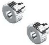 - 2 x Canopy Knobs. - 2 x Canopy Knobs. | Safety Lock Tail Boom[H0038-S]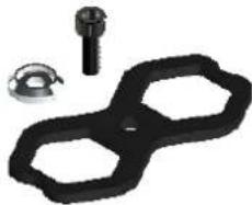 - 1 x Safety Lock Tail Boom.- 1 x Finishing Washer M3.- 1 x Socket Head CapScrews M3x8mm. - 1 x Safety Lock Tail Boom.- 1 x Finishing Washer M3.- 1 x Socket Head CapScrews M3x8mm. |
Locking Element Tail[H0041-S] - 2 x Locking Element Tails.- 4 x Metric Hex Nylon Nuts M3.- 2 x Double Sided Tapes. - 2 x Locking Element Tails.- 4 x Metric Hex Nylon Nuts M3.- 2 x Double Sided Tapes. | Spacer Flybarless[H0043-S]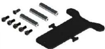 - 3 x Spacer Flybarless.- 1 x Supporto Flybarless.- 1 x Flat Head Cap ScrewsM3x8mm.- 5 x Socket Head Cap ScrewsM3x6mm. - 3 x Spacer Flybarless.- 1 x Supporto Flybarless.- 1 x Flat Head Cap ScrewsM3x8mm.- 5 x Socket Head Cap ScrewsM3x6mm. | Antenna Guide[H0050-S]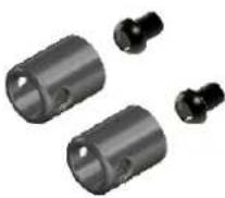 - 2 x Antenna Guide.- 2 x Button Head Cap ScrewsM3x4mm. - 2 x Antenna Guide.- 2 x Button Head Cap ScrewsM3x4mm. | Bell Crank Base[H0058BM-S]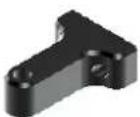 - 1 x Bell Crank Base. - 1 x Bell Crank Base. | |
Tail Case Spacer[H0061-S]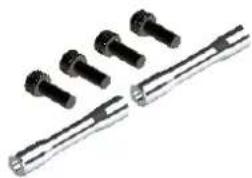 - 2 x Tail Case Spacers.- 4 x Socket Head CapScrews M3x8mm. - 2 x Tail Case Spacers.- 4 x Socket Head CapScrews M3x8mm. | Uniball M3x4 5H18[H0063-S]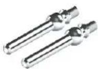 - 1 x Uniball M3x4 5H18. - 1 x Uniball M3x4 5H18. | Uniball M2 5H6[H0K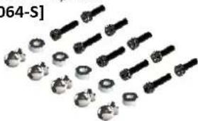 - 5 x Uniballs M2 5H6.- 5 x Uniball Spacers.- 5 x Socket Head Cap ScrewsM2x8mm.- 5 x Socket Head Cap ScrewsM2x6mm. - 5 x Uniballs M2 5H6.- 5 x Uniball Spacers.- 5 x Socket Head Cap ScrewsM2x8mm.- 5 x Socket Head Cap ScrewsM2x6mm. | Uniball M3x4 5H3[H0065-S]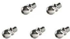 - 5 x Uniballs M3x4 5H3.5. - 5 x Uniballs M3x4 5H3.5. | |
Plastic Ball Link[H0066-S]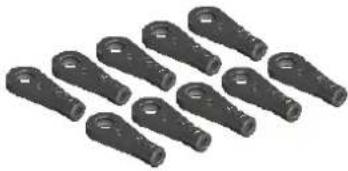 - 10 x Plastic Ball Link. - 10 x Plastic Ball Link. | Belt Tensioner Support[H0834-S]- 1 x Column Belt Tensioner.- 1 x Tail Belt Idler.- 1 x Belt Tensioner Arm.- 2 x Flanged Bearings 3x 7x3r- 2 x Flanged Bearings 5x 9x3r- 1 x Socket Head Cap Screw M3x50mm.- 1 x Washer 3x 4x0.5mm.- 1 x Socket Head Cap Screw M3x12mm.- 2 x Washers 3.2x 6x0.5mm.- 1 x Button Head Cap Screw M3x4mm.- 1 x Spring De8/df0.5/LL8. | 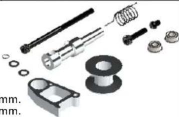 | Servo Spacer[H0075-S]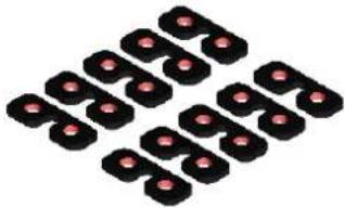 - 10 x Servo Spacers. - 10 x Servo Spacers. | |
| Washer 3.1x 12x1.8mm [H0078-S] | Boom Spacer[H0082-S] | Front Tail Pulley[H0101-S] | One Way Pulley[H0104-S] | Bush One Way[H0110-S] |
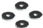 - 10 x Washers 3.1x 12x1.8. - 10 x Washers 3.1x 12x1.8. | 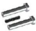 - 2 x Boom Spacer.- 1 x Set Screw M3x20. - 2 x Boom Spacer.- 1 x Set Screw M3x20. | 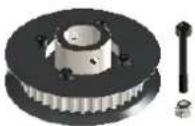 - 1 x Front Tail Pulley.- 1 x Socket HeadM2.5x19mm.- 1 x Metric NylonNuts M2,5. - 1 x Front Tail Pulley.- 1 x Socket HeadM2.5x19mm.- 1 x Metric NylonNuts M2,5. |  - 2 x Brass Bushing.- 2 x Radial Bearings 10x 15x4mm. - 1 x One Way Bearing 10x 14x12mm. - 1 x Aluminum Pulley 60T. - 2 x Brass Bushing.- 2 x Radial Bearings 10x 15x4mm. - 1 x One Way Bearing 10x 14x12mm. - 1 x Aluminum Pulley 60T. | 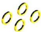 - 4 x Bush One Ways. - 4 x Bush One Ways. |
| M4 Locking Collar[H0121-S] | 18T Pulley[H0126-18-S] | 19T Pulley[H0126-19-S] | 19T Pulley[H0126-20-S] | 19T Pulley[H0126-21-S] |
 - 1 x M4 Locking Collar.- 1 x Socket Head CapScrew M4x22mm.- 1 x Nylon Nut M4. - 1 x M4 Locking Collar.- 1 x Socket Head CapScrew M4x22mm.- 1 x Nylon Nut M4. | 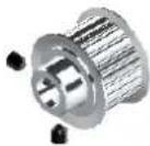 - 1 x 18T Pulley.- 2 x Set Screws M4x4mm. - 1 x 18T Pulley.- 2 x Set Screws M4x4mm. | 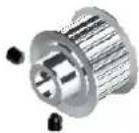 - 1 x 19T Pulley.- 2 x Set Screws M4x4mm. - 1 x 19T Pulley.- 2 x Set Screws M4x4mm. | 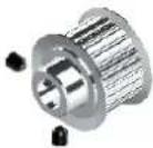 - 1 x 20T Pulley.- 2 x Set Screws M4x4mm. - 1 x 20T Pulley.- 2 x Set Screws M4x4mm. | 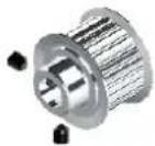 - 1 x 21T Pulley.- 2 x Set Screws M4x4mm. - 1 x 21T Pulley.- 2 x Set Screws M4x4mm. |
| 19T Pulley[H0126-22-S] | 19T Pulley[H0126-23-S] | 19T Pulley[H0126-24-S] | Main Shaft[H0127-S]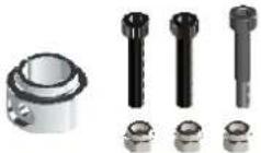 - 1 x Main Shaft.- 1 x M4 Locking Collar.- 1 x Socket Head Cap Screw Shouldered M4x24mm.- 2 x Socket Head Cap Screws M4x22mm.- 3 x Nylon Nuts M4. - 1 x Main Shaft.- 1 x M4 Locking Collar.- 1 x Socket Head Cap Screw Shouldered M4x24mm.- 2 x Socket Head Cap Screws M4x22mm.- 3 x Nylon Nuts M4. | |
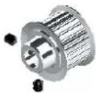 - 1 x 22T Pulley.- 2 x Set Screws M4x4mm. - 1 x 22T Pulley.- 2 x Set Screws M4x4mm. | 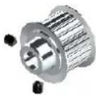 - 1 x 23T Pulley.- 2 x Set Screws M4x4mm. - 1 x 23T Pulley.- 2 x Set Screws M4x4mm. | 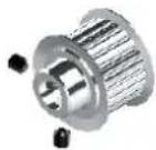 - 1 x 24T Pulley.- 2 x Set Screws M4x4mm. - 1 x 24T Pulley.- 2 x Set Screws M4x4mm. | ||
| Radius Arm[H0132-S]-2 x Radius Arms.-2 x Spacer Arm 3x -2 x Spacer Arm 2.5x 4x6.3mm .-2 x Uniball Radius Arms.-2 x Socket Head Cap Screws M3x16mm.-2 x Socket Head Cap Screws M2.5x18mm.-2 x Washers 3x 4x0.5mm .-2 x Flanged Bearings 2.5x 6x2.5mm .-2 x Flanged Bearings 3x 7x3mm . | 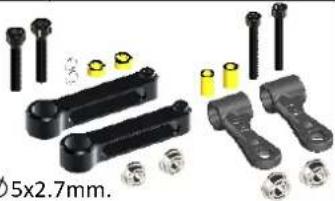 | Motor Mount[H0142-S]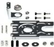 - 1 x Bearing 3 ° Support.- 1 x Motor Support.- 1 x Flanged Bearing 6x 13x5mm .- 2 x Head Cap Screws M3x8.- 2 x Set Screws M5x20mm.- 2 x Washers 5.3x 15x1 .- 2 x Nylon Nuts M5H4.8.- 2 x Finishing Washers M3.- 2 x Head Cap Screws M3x10.- 2 x Nylon Nut M3 H4.- 2 x Springs de 5.8/ df0.5 / LL9.- 2 x Springs de 3/ df0.5 / LL12. - 1 x Bearing 3 ° Support.- 1 x Motor Support.- 1 x Flanged Bearing 6x 13x5mm .- 2 x Head Cap Screws M3x8.- 2 x Set Screws M5x20mm.- 2 x Washers 5.3x 15x1 .- 2 x Nylon Nuts M5H4.8.- 2 x Finishing Washers M3.- 2 x Head Cap Screws M3x10.- 2 x Nylon Nut M3 H4.- 2 x Springs de 5.8/ df0.5 / LL9.- 2 x Springs de 3/ df0.5 / LL12. | Bearing Support[H0143-S]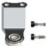 - 1 x Bearing 3 °Support.- 1 x Flanged Bearing 6x 13x5mm .- 2 x Socket Head CapScrews M3x8mm. - 1 x Bearing 3 °Support.- 1 x Flanged Bearing 6x 13x5mm .- 2 x Socket Head CapScrews M3x8mm. | |
Battery Tray[H0149-S] - 1 x Battery Plate.- 1 x Battery Protection.- 2 x Cylinder M2.5.- 2 x Flat Head CapScrew M2.5x5mm.- 1 x Heat Shrink. - 1 x Battery Plate.- 1 x Battery Protection.- 2 x Cylinder M2.5.- 2 x Flat Head CapScrew M2.5x5mm.- 1 x Heat Shrink. | Stop Battery Tray[H0150-S]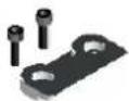 - 1 x Stop Battery Tray.- 2 x Socket Head CapScrews M2.5x8mm. - 1 x Stop Battery Tray.- 2 x Socket Head CapScrews M2.5x8mm. | SwashplateAnti-Rotation Guide[H0152-S]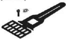 - 1 x CF SwashplateAnti-Rotation Guide.- 1 x Finishing Washer M3.- 1 x Socket Head CapScrew M3x8mm. - 1 x CF SwashplateAnti-Rotation Guide.- 1 x Finishing Washer M3.- 1 x Socket Head CapScrew M3x8mm. | Carbon Fiber ESC Support(H0153-S)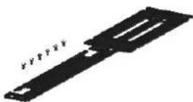 - 1 x ESC Support.- 6 x Flat Head Socket CapM2,5x5mm. - 1 x ESC Support.- 6 x Flat Head Socket CapM2,5x5mm. | 24T Tail Pulley[H0154-S]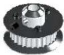 - 1 x 24T Tail Pulley.- 1 x Set Screw M4x4mm.- 6 x Socket Head CapScrews M2x5mm. - 1 x 24T Tail Pulley.- 1 x Set Screw M4x4mm.- 6 x Socket Head CapScrews M2x5mm. |
25T Tail Pulley[H0155-S]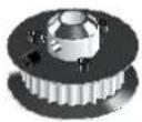 - 1 x 25T Tail Pulley.- 1 x Set Screw M4x4mm.- 6 x Socket Head Cap Screws M2x5mm. - 1 x 25T Tail Pulley.- 1 x Set Screw M4x4mm.- 6 x Socket Head Cap Screws M2x5mm. | Steel Pinion Z19[H0156-S]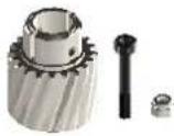 - 1 x Steel Pinion Z19.- 1 x Socket Head Cap M3x22 Shoulder.- 1 x Metric hex locknut Nuts M3H4. - 1 x Steel Pinion Z19.- 1 x Socket Head Cap M3x22 Shoulder.- 1 x Metric hex locknut Nuts M3H4. | Secondary Shaft[H0157-S]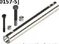 - 1 x Secondary Shaft M3.- 1 x Head Cap Shouldered M2.5x19mm.- 1 x Nylon Nut M2,5- 1 x Head Cap Shouldered M3x22mm.- 1 x Nylon Nuts M3. - 1 x Secondary Shaft M3.- 1 x Head Cap Shouldered M2.5x19mm.- 1 x Nylon Nut M2,5- 1 x Head Cap Shouldered M3x22mm.- 1 x Nylon Nuts M3. | Aluminum Blade Spacer[H0158-S]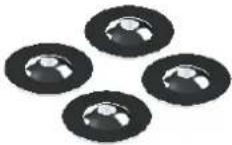 - 4 x Aluminum Blade Spacer. - 4 x Aluminum Blade Spacer. | Plastic Radius Arm[H0205-S]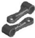 - 2 x Plastic Radius Arm. - 2 x Plastic Radius Arm. |
Finishing Washer M2.5[H0255-S]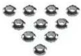 - 10 x Washer M2.5. - 10 x Washer M2.5. | Plastic Tail Linkage[H0261-S]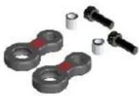 - 2 x Plastic Tail Linkage.- 2 x Grip Link Bushing.- 2 x Socket Head Cap Screws M2x6mm. - 2 x Plastic Tail Linkage.- 2 x Grip Link Bushing.- 2 x Socket Head Cap Screws M2x6mm. | Steel Tail Shaft[H0325-S]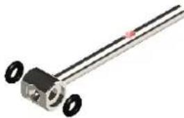 - 1 x Tail Shaft Assembly.- 2 x Tail Oring Damperner. - 1 x Tail Shaft Assembly.- 2 x Tail Oring Damperner. | Aluminum Tail Blade Grip[H0327BM-S]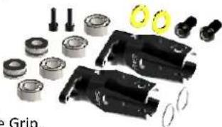 - 2 x Aluminum Tail Blade.- 4 x Bearing 5 × 10 × 4 mm.- 2 x Thrust bearing 5 × 10 × 4 mm.- 2 x Button Head Cap M4x8mm.- 2 x Socket Head Cap M2x6mm.- 2 x Washer 5 × 8.9 × 0.75 mm.- 2 x Washer 7.5 × 10 × 0.5 mm. - 2 x Aluminum Tail Blade.- 4 x Bearing 5 × 10 × 4 mm.- 2 x Thrust bearing 5 × 10 × 4 mm.- 2 x Button Head Cap M4x8mm.- 2 x Socket Head Cap M2x6mm.- 2 x Washer 5 × 8.9 × 0.75 mm.- 2 x Washer 7.5 × 10 × 0.5 mm. | |
Tail Spilde Shaft[H0329-S]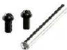 - 1 x Tail Spilde Shaft.- 2 x Button Head Cap Screws M4x6mm. - 1 x Tail Spilde Shaft.- 2 x Button Head Cap Screws M4x6mm. | Spacer Set For Tail Rotor[H0330-S]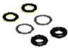 - 2 x Washer 5 × 8.9 × 0.75 mm.- 2 x Washer 7.5 × 10 × 0.5 mm.- 2 x Tail Oring Damperner. - 2 x Washer 5 × 8.9 × 0.75 mm.- 2 x Washer 7.5 × 10 × 0.5 mm.- 2 x Tail Oring Damperner. | Tail Boom Support[H0358-S]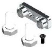 - 1 x Tail Boom Support.- 1 x Nylon screw M8x20.- 1 x Flat Head Cap ScrewsM3x8mm. - 1 x Tail Boom Support.- 1 x Nylon screw M8x20.- 1 x Flat Head Cap ScrewsM3x8mm. | Tail Boom Support[H0394-S]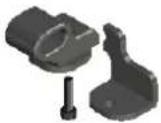 - 1 x Plastic Carbon Rod Support.- 1 x Finishing Washer M2.5.- 1 x Socket Head Cap Screws M2,5x10mm. - 1 x Plastic Carbon Rod Support.- 1 x Finishing Washer M2.5.- 1 x Socket Head Cap Screws M2,5x10mm. | Ball Link[H0402-S]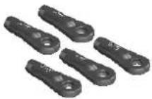 - 5 x Ball Link. - 5 x Ball Link. |
CNC Delrin Main Gear[H0405-S]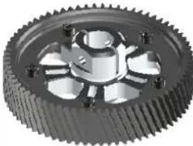 - 1 x CNC Delrin Main Gear. - 1 x CNC Delrin Main Gear. | Bell Crank Lever[H0406BM-S]- 2 x Tail Pin.- 1 x Uniball M2.- 1 x Uniball Spacer.- 1 x Bell Crank Lever.- 2 x Flanged Bearing 3 × 7.5 × 0.5 mm.- 1 x Head Cap Screws M3x22mm.- 1 x Head Cap Screws M2x8mm.- 1 x Washer 3 × 4 × 0.5 mm.- 1 x Spacer 3 x 4 x 9.6mm. | 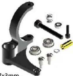 | Tail Pitch Slider[H0407BM-S]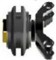 - 1 x Tail Pitch Slider 01.- 1 x Tail Pitch Slider 02.- 1 x Tail Pitch Slider 03.- 1 x Spacer 8 × 9 × 3.2 mm.- 2 x Flanged Bearings 8 × 12 × 3.5 mm - 1 x Tail Pitch Slider 01.- 1 x Tail Pitch Slider 02.- 1 x Tail Pitch Slider 03.- 1 x Spacer 8 × 9 × 3.2 mm.- 2 x Flanged Bearings 8 × 12 × 3.5 mm | SwashPlate Set[H0422BM-S]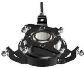 - 1 x Swashplate Assembly SET. - 1 x Swashplate Assembly SET. |
Tail Servo Support[H0436-S]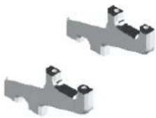 - 2 x Tail Servo Support. - 2 x Tail Servo Support. | Top Position ESC Suppc[H0450-S]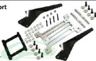 - 4 x Set Screws M3x20.- 4 x Nylon Nut M3.- 2 x Carbon Fiber Top ESC Support.- 1 x Aluminum Top ESC Support.- 4 x Socket Screw M3x8.- 4 x Socket Screw M3x10.- 8 x Aluminum Washer M3.- 12 x Washer 3,3 × 6 × 0.5 mm. - 4 x Set Screws M3x20.- 4 x Nylon Nut M3.- 2 x Carbon Fiber Top ESC Support.- 1 x Aluminum Top ESC Support.- 4 x Socket Screw M3x8.- 4 x Socket Screw M3x10.- 8 x Aluminum Washer M3.- 12 x Washer 3,3 × 6 × 0.5 mm. | Center Hurb[H0479BM-]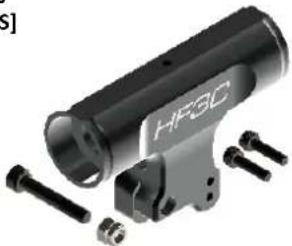 - 1 x Center Hub.- 2 x Socket Head Cap Screws M3x12mm.- 1 x Socket Head Cap Screw Shouldered M4x24mm.- 1 x Metric Hex Nylon Nut M4. - 1 x Center Hub.- 2 x Socket Head Cap Screws M3x12mm.- 1 x Socket Head Cap Screw Shouldered M4x24mm.- 1 x Metric Hex Nylon Nut M4. | ||
Spindle[H0481-S]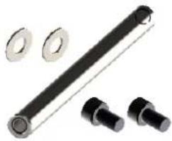 - 1 x Spindle.- 2 x Head Cap Screw M6x10.- 2 x Washer ∅6x∅14x1.5. - 1 x Spindle.- 2 x Head Cap Screw M6x10.- 2 x Washer ∅6x∅14x1.5. | Damper[H0482-60-S]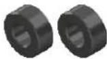 - 1 x Damper 60 Shore. - 1 x Damper 60 Shore. | Damper[H0482-70-S]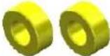 - 1 x Damper 70 Shore. - 1 x Damper 80 Shore. - 1 x Damper 90 Shore. - 1 x Damper 70 Shore. - 1 x Damper 80 Shore. - 1 x Damper 90 Shore. | Damper[H0482-80-S] | Damper[H0482-90-S]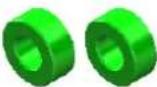 |
Carbon Tail Side Plate[H0494-S]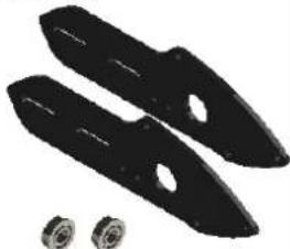 - 2 x CarbonTail Side Plate.- 2 x Flanged Bearing∅6x∅13x5mm. - 2 x CarbonTail Side Plate.- 2 x Flanged Bearing∅6x∅13x5mm. | Tail Servo Support[H0495-S] - 1 x Tail Servo Support. - 1 x Tail Servo Support. | Landing Gear Support[H0496-S]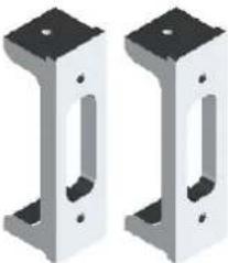 - 2 x Landing Gear Support. - 2 x Landing Gear Support. | Wire Support[H0497-S]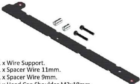 - 1- 1- 1- 2 x Head Cap Shoulder M3x18mm. - 1- 1- 1- 2 x Head Cap Shoulder M3x18mm. | |
Landing Gear White[H0639-S]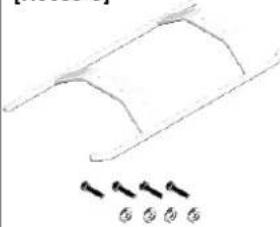 - 1 x Landing Gear White.- 4 x Head Cap Screw M3x12.- 4 x Aluminum Washer M3. - 1 x Landing Gear White.- 4 x Head Cap Screw M3x12.- 4 x Aluminum Washer M3. | Main Blade Grip[H0719BM-S]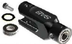 - 1 x Main Blade Grip.- 2 x Bearing ∅10x∅19x5.- 1 x Thrust Bearing∅10x∅18x5,5.- 1 x Shims ∅10x∅16x 1.- 1 x Head Cap Screw M4x10. - 1 x Main Blade Grip.- 2 x Bearing ∅10x∅19x5.- 1 x Thrust Bearing∅10x∅18x5,5.- 1 x Shims ∅10x∅16x 1.- 1 x Head Cap Screw M4x10. | Titanium Main Linkage[H0722-S]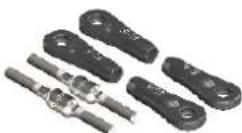 - 2 x Titanium Main Linkage.- 4 x Plastic Ball Link. - 2 x Titanium Main Linkage.- 4 x Plastic Ball Link. | Canopy Urukay Carbon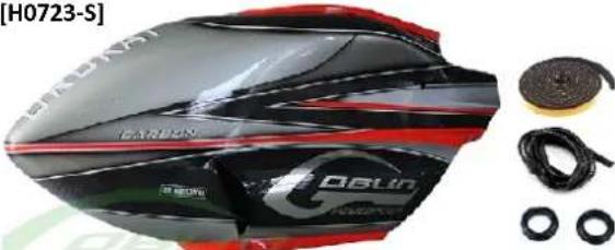 - 1 x Canopy Urukay Carbon.- 2 x Canopy Grommet.- 1 x Canopy Mousse.- 3 x Canopy Edge Protection. - 1 x Canopy Urukay Carbon.- 2 x Canopy Grommet.- 1 x Canopy Mousse.- 3 x Canopy Edge Protection. | |
Boom Urukay Carbon[H0724-S]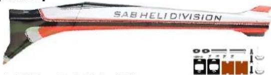 - 1 x Tail Boom Ennio Graber Edition.- 2 x Locking Element Tails.- 1 x Set Screws M3 x 20mm.- 2 x Washers 3.1 x 12 x 1.8mm.- 4 x Metric Hex Nylon Nuts M3.- 2 x Head Cap Screws M3x12mm.- 2 x Nylon Screw M8x20mm.- 1 x Flat Head Cap Screws M3x8mm. - 1 x Tail Boom Ennio Graber Edition.- 2 x Locking Element Tails.- 1 x Set Screws M3 x 20mm.- 2 x Washers 3.1 x 12 x 1.8mm.- 4 x Metric Hex Nylon Nuts M3.- 2 x Head Cap Screws M3x12mm.- 2 x Nylon Screw M8x20mm.- 1 x Flat Head Cap Screws M3x8mm. | - 2 x Boom spacers.- 2 x Double-Sided Tapes. | Landing Gear Silver[H0725-S]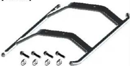 - 1 x Landing Gear Silver.- 4 x Head Cap Screw M3x12.- 4 x Aluminum Washer M3. - 1 x Landing Gear Silver.- 4 x Head Cap Screw M3x12.- 4 x Aluminum Washer M3. | Blades Grip Arm Black Matte HF3C[H0817BM-S]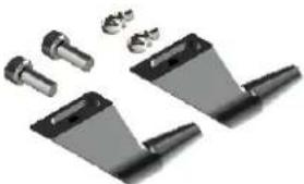 - 2 x Blade Grip Arm BM.- 2 x Head Cap Screw M4x10.- 2 x Uniball M3x4 ∅5 H3.5. - 2 x Blade Grip Arm BM.- 2 x Head Cap Screw M4x10.- 2 x Uniball M3x4 ∅5 H3.5. | |
 - 1 x Canopy Ennio Graber Edition.- 2 x Canopy Grommet.- 1 x Canopy Mousse.- 3 x Canopy Edge Protection. - 1 x Canopy Ennio Graber Edition.- 2 x Canopy Grommet.- 1 x Canopy Mousse.- 3 x Canopy Edge Protection. | Tail Boom Ennio Graber Edition[H0822-S]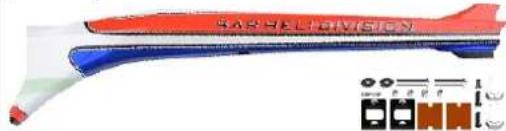 - 1 x Tail Boom Ennio Graber Edition.- 2 x Locking Element Tails.- 1 x Set Screws M3 x 20mm.- 2 x Washers 3.1 x 12 x 1.8mm.- 4 x Metric Hex Nylon Nuts M3.- 2 x Head Cap Screws M3x12mm.- 2 x Nylon Screw M8x20mm.- 1 x Flat Head Cap Screw M3x8mm. - 1 x Tail Boom Ennio Graber Edition.- 2 x Locking Element Tails.- 1 x Set Screws M3 x 20mm.- 2 x Washers 3.1 x 12 x 1.8mm.- 4 x Metric Hex Nylon Nuts M3.- 2 x Head Cap Screws M3x12mm.- 2 x Nylon Screw M8x20mm.- 1 x Flat Head Cap Screw M3x8mm. | Composite Tail Fin Red[H0823-S]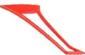 - 1 x Composite Tail Fin Red. - 1 x Composite Tail Fin Red. | Carbon Fiber Main Frame[H0824-S]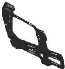 - 1 x Main Frame. - 1 x Main Frame. | |
[HC002-S] [HC004-S] [HC008-S]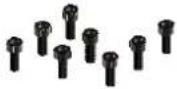 - 8 x Socket Head Cap Screws M2x5mm. - 8 x Socket Head Cap Screws M2x5mm. | 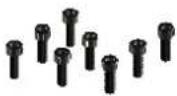 - 8 x Socket Head Cap Screws M2x6mm. - 8 x Socket Head Cap Screws M2x6mm. | 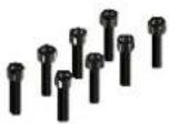 - 8 x Socket Head Cap Screws M2x8mm. - 8 x Socket Head Cap Screws M2x8mm. | [HC010-S] [HC018-S] - 8 x Socket Head Cap Screws M2x10mm. - 8 x Socket Head Cap Screws M2x10mm. | 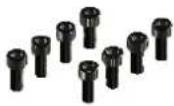 - 8 x Socket Head Cap Screws M2.5x6mm. - 8 x Socket Head Cap Screws M2.5x6mm. | [HC020-S]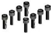 - 8 x Socket Head Cap Screws M2.5x8mm. - 8 x Socket Head Cap Screws M2.5x8mm. |
[HC026-S]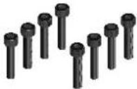 - 8 x Socket Head Cap Screw M2.5x12mm. - 8 x Socket Head Cap Screw M2.5x12mm. | [HC033-S]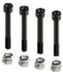 - 4 x Socket Head Shoulder M2.5x19mm.- 4 x Metrix Hex Nylon Nut M2.5. - 4 x Socket Head Shoulder M2.5x19mm.- 4 x Metrix Hex Nylon Nut M2.5. | [HC038-S]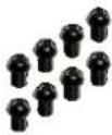 - 8 x Button Head Cap Screws M3x4mm. - 8 x Button Head Cap Screws M3x4mm. | [HC044-S] [HC050-S] [HC056-S] - 8 x Socket Head Cap Screws M3x6mm. - 8 x Socket Head Cap Screws M3x6mm. | 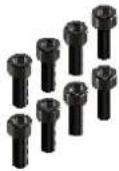 - 8 x Socket Head Cap Screws M3x8mm. - 8 x Socket Head Cap Screws M3x8mm. | 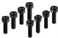 - 8 x Socket Head Cap Screws M3x10mm. - 8 x Socket Head Cap Screws M3x10mm. |
[HC062-S]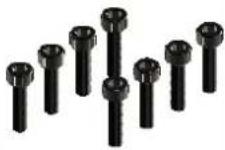 - 8 x Socket Head Cap Screws M3x12mm. - 8 x Socket Head Cap Screws M3x12mm. | [HC068-S]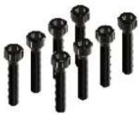 - 8 x Socket Head Cap Screws M3x16mm. - 8 x Socket Head Cap Screws M3x16mm. | [HC079-S] [HC086-S]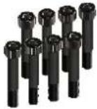 - 8 x Socket Head Cap Shoulder M3x18mm. - 8 x Socket Head Cap Shoulder M3x18mm. | 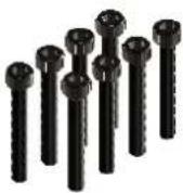 - 8 x Socket Head Cap Screws M3x22mm. - 8 x Socket Head Cap Screws M3x22mm. | [HC7A8X]- 4 x Socket Head Shoulder M3x40mm. | [HC096-S]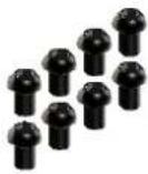 - 8 x Button Head Cap Screws M4x6mm. - 8 x Button Head Cap Screws M4x6mm. |
[HC098-S]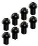 - 8 x Button Head Cap Screws M4x8mm. - 8 x Button Head Cap Screws M4x8mm. | [HC100-S]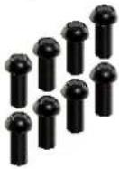 - 8 x Button Head Cap Screws M4x10mm. - 8 x Button Head Cap Screws M4x10mm. | [HC10* 61]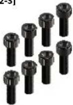 - 8 x Socket Head Cap Screws M4x10mm. - 8 x Socket Head Cap Screws M4x10mm. | [HC104-S]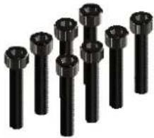 - 8 x Socket Head Cap Screws M4x22mm. - 8 x Socket Head Cap Screws M4x22mm. | [HC116-S]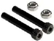 - 2 x Socket Head Cap Shoulder M5x35mm.- 2 x Metrix Hex Nut M5. - 2 x Socket Head Cap Shoulder M5x35mm.- 2 x Metrix Hex Nut M5. | |
[HC122-S] [HC152-S][HC152-S][HC152-S][HC152-S][HC152-S][HC152-S][HC152-S][HC152-S][HC152-S][HC152-S][HC152-S][HC152-S][HC152-S][HC152-S][HC152-S][HC152-S][HC152-S][HC153-S][HC170-S]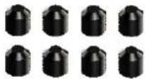 - 8 x Cup Poin Set Screws M4x6mm. - 8 x Cup Poin Set Screws M4x6mm. | [HC16128-S]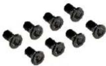 - 8 x Flat Head Cap Screws M2.5x5mm. - 8 x Flat Head Cap Screws M2.5x5mm. | [HC176-S] [HC181-S] - 5 x Washer Ø3xØ4x0,5mm. - 5 x Washer Ø3xØ4x0,5mm. | [HC140-S]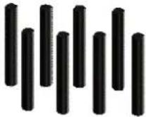 - 8 x Cup Poin Set Screws M2.5x20mm.- 10 x Washer Ø3xØ7x1mm. - 8 x Cup Poin Set Screws M2.5x20mm.- 10 x Washer Ø3xØ7x1mm. | 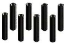 - 8 x Cup Poin Set Screws M3x20mm.- 5 x Washer Ø5.3xØ15x1mm. - 8 x Cup Poin Set Screws M3x20mm.- 5 x Washer Ø5.3xØ15x1mm. |  - 8 x Cup Poin Set Screws M4x4mm. - 8 x Cup Poin Set Screws M4x4mm. |
[HC200-S] [HC206-S]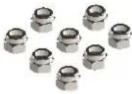 - 10 x Metric Hex Nylon Nuts M2,5H3,5. - 10 x Metric Hex Nylon Nuts M2,5H3,5. |  - 10 x Metric Hex Nylon Nuts M3H4. - 10 x Metric Hex Nylon Nuts M3H4. | [HC212-S] [HC218-S] [HC230-S]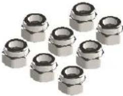 - 10 x Metric Hex Nylon Nuts M4H5. - 10 x Metric Hex Nylon Nuts M4H5. | 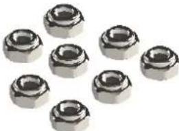 - 5 x Metric Hex Nylon Nuts M5H4.5. - 5 x Metric Hex Nylon Nuts M5H4.5. |  - 5 x Shims∅10x∅16x1mm. - 5 x Shims∅10x∅16x1mm. |
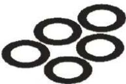 - 5 x Shims∅10x∅16x0.2mm. - 5 x Shims∅10x∅16x0.2mm. | 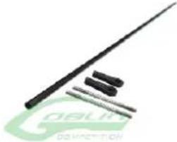 - 1 x Carbon Rod∅4x∅2,5x851mm.- 2 x Plastic Ball Linkage.- 2 x Thread Rod M2.5x40mm. - 1 x Carbon Rod∅4x∅2,5x851mm.- 2 x Plastic Ball Linkage.- 2 x Thread Rod M2.5x40mm. | [HC242-S][HC451-S] [HC325-S]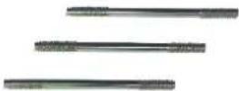 - 3 X Thread RodsM2.5x40mm. - 3 X Thread RodsM2.5x40mm. | [HC232-S] [HC308-S]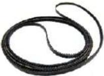 - 1 x Main Belt. - 1 x Main Belt. | 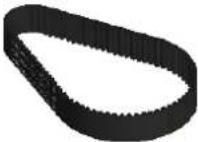 - 1 x Motor Belt240-3MGT 13mm. - 1 x Motor Belt240-3MGT 13mm. |
[HC315-S]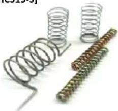 - 2 x Spring 5,8/df 0,3/LL 9.- 1 x Spring 8 /df 0,5 / LL 8.- 2 x Spring 3 /df 5 / LL 12. - 2 x Spring 5,8/df 0,3/LL 9.- 1 x Spring 8 /df 0,5 / LL 8.- 2 x Spring 3 /df 5 / LL 12. | [HC400-S] - 4 x Flanged Bearings∅2.5x∅6x2.6mm. - 4 x Flanged Bearings∅2.5x∅6x2.6mm. | [HC402-S] - 4 x Flanged Bearings∅3x∅7x3mm. - 4 x Flanged Bearings∅3x∅7x3mm. | [HC410-S]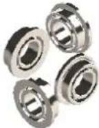 - 4 x Flanged Bearings∅5x∅9x3mm. - 4 x Flanged Bearings∅5x∅9x3mm. | [HC411-S]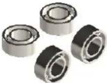 - 4 x Bearings∅5x∅10x4mm. - 4 x Bearings∅5x∅10x4mm. |
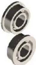 - 2 x Flanged Bearings∅6x∅13x4mm. - 2 x Flanged Bearings∅6x∅13x4mm. | 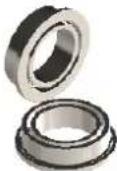 - 2 x Flanged Bearings∅8x∅12x3.5mm. - 2 x Flanged Bearings∅8x∅12x3.5mm. | [HC420-S][HC414-S] [HC418-S]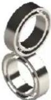 - 2 x Bearings∅10x∅15x4mm. - 2 x Bearings∅10x∅15x4mm. | [HC422-S]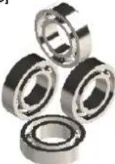 - 4 x Bearings∅10x∅19x5mm. - 4 x Bearings∅10x∅19x5mm. | [HC426-S]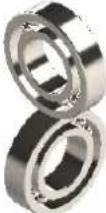 - 2 x Bearings∅12x∅24x6mm. - 2 x Bearings∅12x∅24x6mm. |
[HC430-S] [HC435-S]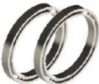 - 2 x Rad Bearings∅30x∅37x4mm. - 2 x Rad Bearings∅30x∅37x4mm. | 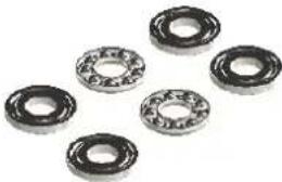 - 2 x Thrust Bearings∅5x∅10x4mm. - 2 x Thrust Bearings∅5x∅10x4mm. | [HC438-S]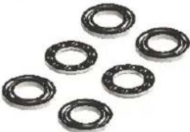 - 2 x Thrust Bearings∅10x∅18x5.5mm. - 2 x Thrust Bearings∅10x∅18x5.5mm. | [HC442-S]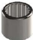 - 1 x One Way Bearings∅10x∅14x12mm. - 1 x One Way Bearings∅10x∅14x12mm. | [HA016-S]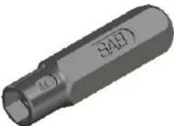 - 1 x Wrench Tool M8,M6. - 1 x Wrench Tool M8,M6. |
[HA026-S]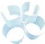 - 8 x Heat Shrink - Clear. - 8 x Heat Shrink - Clear. |  - 1 x Blade Holder. - 1 x Blade Holder. | [HA112-S][HA001-S] - 1 x Rubber CanopyEdge Protection. - 1 x Rubber CanopyEdge Protection. | [730TB-S]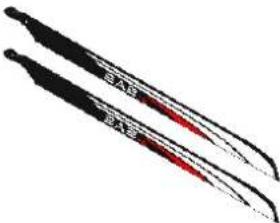 - 2 x Main Blade. - 2 x Main Blade. | [11STB >> SG725][10STB >> SG726]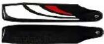 - 2 x Tail Blade. - 2 x Tail Blade. |
UPGRADES and ACCESSORIES
Damper[H0482-70-S] 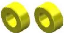 70° Shore[H0482-90-S]90° Shore 70° Shore[H0482-90-S]90° Shore | Tail Pulley[H0103-S] (26T) [H0102-S] (27T) [H0154-S] (25T) [H0154-S] (25T) | Delrin CNC Precision Antirotation Guide(H0458-S)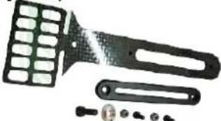 - 1 x Carbon Fiber Antirotation Guide Support.- 1 x CNC Plastic Guide.- 1 x Socket Head Cap Screw M2.5x10.- 1 x Nylon Nut M2.5.- 1 x Socket Head Cap Screw M3x8.- 1 x Aluminum M3 Washer. - 1 x Carbon Fiber Antirotation Guide Support.- 1 x CNC Plastic Guide.- 1 x Socket Head Cap Screw M2.5x10.- 1 x Nylon Nut M2.5.- 1 x Socket Head Cap Screw M3x8.- 1 x Aluminum M3 Washer. |
Quick release Canopy Knob(H0714-S)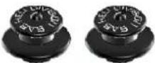 - 2 x Quick Release Canopy Knob. - 2 x Quick Release Canopy Knob. | SAB HELIDIVISIONFutaba Servo Horn[HA050-S]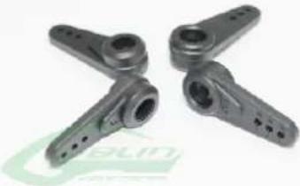 - 4 x Plastic Servo Horn. - 4 x Plastic Servo Horn. | SAB HELIDIVISIONJR Servo Horn[HA051-S]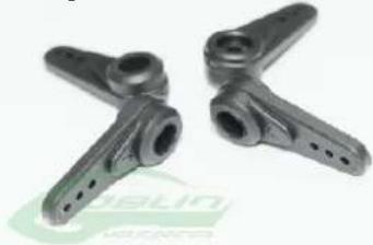 - 4 x JR Servo Horn. - 4 x JR Servo Horn. |
Short Main Shaft[H0122-S] + [H0459-S] + [HC140-S]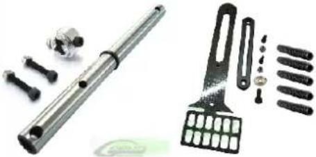 | Carbon Fuselage ready to paint [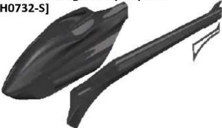 - 1 x Canopy Carbon Ready to Paint.- 1 x Boom Carbon Ready to Paint.- 1 x Tail Fin Carbon Ready to Paint.- Hardwares for Boom and Canopy. - 1 x Canopy Carbon Ready to Paint.- 1 x Boom Carbon Ready to Paint.- 1 x Tail Fin Carbon Ready to Paint.- Hardwares for Boom and Canopy. | SAB HELIDIVISION Team Cap - Black[HM003-S] - 1 x Team Cap - Black. - 1 x Team Cap - Black. |
SAB HELI DIVISION New Black T-shirt[HM025-S-M-L-XL-XXL] - SAB HELI DIVISION New Black T-shirt. - SAB HELI DIVISION New Black T-shirt. | SAB HELI DIVISION Black Polo Shirt[HM027-S-M-L-XL-XXL] - SAB HELI DIVISION Black Polo Shirt. - SAB HELI DIVISION Black Polo Shirt. | SAB HELI DIVISION Black Hoodies[HM029-S-M-L-XL-XXL] - SAB HELI DIVISION Black Hoodies. - SAB HELI DIVISION Black Hoodies. |
SAB HELI DIVISION Neck Strap[HM034-S] - 1 x Neck Strap. - 1 x Neck Strap. | SAB Transmitter Case[HM055-S]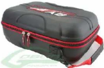 - 1 x Transmitter Case. - 1 x Transmitter Case. | Sab Goblin 630/700/770/Urukay Competition/Speed Carry Bag[HM060-S]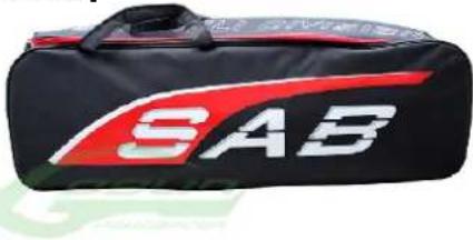 - 1 x Carry Bag. - 1 x Carry Bag. |
The new Goblin Urukay Carbon with its important changes, improves an already successful helicopter and makes it the pinnacle for competitions.
The differences and versatility of the Urukay Carbon allow you to experience a new dimension of model helicopter flight.

text_image
S. fulius Ennio Graber F3C WORLD CHAMPION F3C EUROPEAN CHAMPION SABHEL DIVISION Diploma COMPETITION SAB FUTABA POUER TRANSFER DELA PLACE OF CATH-2014 ENNO. GRABER- M. GUSTIN

WWW.GOBLIN-HELICOPTER.COM
WWW.SABITALY.IT