
YZ667A1060 - Temperature regulator HONEYWELL - Free user manual and instructions
Find the device manual for free YZ667A1060 HONEYWELL in PDF.

| Brand | Honeywell |
| Model | YZ667A1060 |
| Product Type | Wireless Domestic Heating Zoning System |
| Components | CM67z Room Unit, HC60NG Relay Module, HR80UK Radiator Controllers (x6) |
| Dimensions (Room Unit) | 155 x 105 x 30 mm (L x H x D) |
| Dimensions (Radiator Controller) | 50 x 80 x 105 mm |
| Dimensions (Relay Module) | 131 x 97 x 36 mm |
| Power Supply (Room Unit) | 2 x 1.5V IEC LR6 (AA) alkaline cells |
| Power Supply (Radiator Controller) | 2 x 1.5V IEC LR6 (AA) alkaline cells |
| Power Supply (Relay Module) | 230 V~ 50 Hz mains |
| Relay Output Rating | 24-230 V~, 10A resistive, 3A inductive |
| Number of Zones | 2 |
| Programming Capability | 7-day, 6 temperature changes per day per zone |
| Wireless Range | Up to 30 m (typical building fabric) |
| Valve Compatibility | M30 x 1.5 mm thread, 12.9-10.5 mm valve closing point |
| Approvals | CE, EN60730, EN55014, ETSI EN300 220-3 |
| Housing Material | ABS plastic |
| Weight (Room Unit, approx.) | 0.2 kg |
| Operating Temperature Range | 0°C to 40°C (estimated) |
| Battery Life (estimated) | Approximately 1 year under normal use |
| Installation | Wall mounting (room unit, relay module) or on TRV body (radiator controller) |
| Functions | Individual zone temperature control, setpoint override, binding, test mode |
| Cleaning and Maintenance | Wipe with dry cloth; do not use solvents or abrasive cleaners |
| Safety Precautions | Electrostatic sensitive; relay module must be installed by qualified installer |
| Spare Parts | Batteries, adaptors for non-standard TRV bodies |
| Environmental Note | Dispose of batteries and product according to local regulations |
Frequently Asked Questions - YZ667A1060 HONEYWELL
User questions about YZ667A1060 HONEYWELL
0 question about this device. Answer the ones you know or ask your own.
Ask a new question about this device
Download the instructions for your Temperature regulator in PDF format for free! Find your manual YZ667A1060 - HONEYWELL and take your electronic device back in hand. On this page are published all the documents necessary for the use of your device. YZ667A1060 by HONEYWELL.
USER MANUAL YZ667A1060 HONEYWELL
Wireless Domestic Heating Zoning System
INSTALLATION GUIDE
HC60NG Relay Module
CM67z Room Unit
HR80UK Radiator Controllers
TABLE OF CONTENTS
Section Page
1 General 1
2 Technical Information .... 1
3 Factory Configuration 2
4 HC60NG Relay Module 3
5 CM67z Room Unit 4
6 HR80UK Radiator Controller .... 5
7 System Testing 6
7.1 Service mode ......6
8 Changing the Configuration ...... 7
8.1 Parameters of the CM67z 7
8.2 Changing or adding a HR80UK to a zone ..... 8
8.3 Built -in sensor configuration 9
8.4 Adding a HC60NG Zone valve controller ..... 9
8.5 Resetting a Bound HR80UK 9
9 Trouble Shooting 10
9.1 Trouble Shooting Guide ....10
9.2 Manual adaption 11
9.3 Def (default setting) and Full operating modes ...11
9.4 Resetting the HR 80 to the factory settings ... 11
1 GENERAL
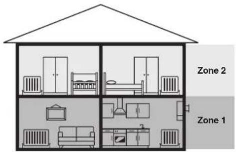
The CM Zone Wireless Domestic Heating Zoning System offers high levels of comfort and energy savings for the home. It provides the ability to control two individual zones at different comfort levels and at different times. A typical example being the living areas and the bedrooms being controlled separately.
The standard CM Zone Pack contains a Room Unit, a Relay Module and six Radiator Controllers all pre-bound with three Radiator Controllers bound to Zone 1 and three bound to Zone 2. The System can be expanded or modified and the methods used are described within this Guide.
To get the best from the installed system it is recommended to use Honeywell VT15, VT117 or VT200 TRV bodies and a Honeywell DU145 Automatic Bypass Valve.
For application support please contact your nearest Honeywell salesman, for technical assistance please contact the Honeywell Technical Help Desk, details are on the back page.
2 TECHNICAL INFORMATION
Type numbers
CM67z - Room Unit (x1)
HR80UK - Radiator Controller (x6)
HC60NG - Relay module (x1)
Material
Housings made of plastics (ABS).
Dimensions
CM67z - 155 x 105 x 30 mm. (I x h x d)
HR80UK - 50 x 80 x 105 mm. (I x h x d)
HC60NG - 131 x 97 x 36 mm. (I x h x d)
Power
CM67z - 2 x 1.5 V IEC LR6 (AA) Alkaline cells
HR80UK - 2 x 1.5 V IEC LR6 (AA) Alkaline cells
HC60NG - 230V\~ 50Hz powered
Electrical wiring (only for HC60NG)
Mains power supply
Relay output rating: 24-230 V\~, 10A resistive,
3A inductive 0.6 p.f.
Programming Capability
2 individual heating programs
7 days with 6 temperature change times per day
Approvals
DIN EN ISO 9001/14001, CE, EN60730-1 (2000), EN60730-2-9 (2002), EN55014-1 (2000), EN55014-2 (1997), ETSI EN300 220-3 (2000), ETSI EN301 489-3 (2000)
Section 3: Factory Configuration
The Hydronic Zoning kit is factory pre-configured and has the following components:
• Zone 1 - Three HR80UK Radiator controllers labelled 1
• Zone 2 - Two HR80UK Radiator controllers labelled 2
- HC60NG - Relay box
- CM67z - Room Unit
To change this factory configuration or to add components please see Section 8: Changing the Configuration.
Zoning Example
Zone 1: Living Room + Kitchen (downstairs)
Zone 2: Bedrooms (upstairs)
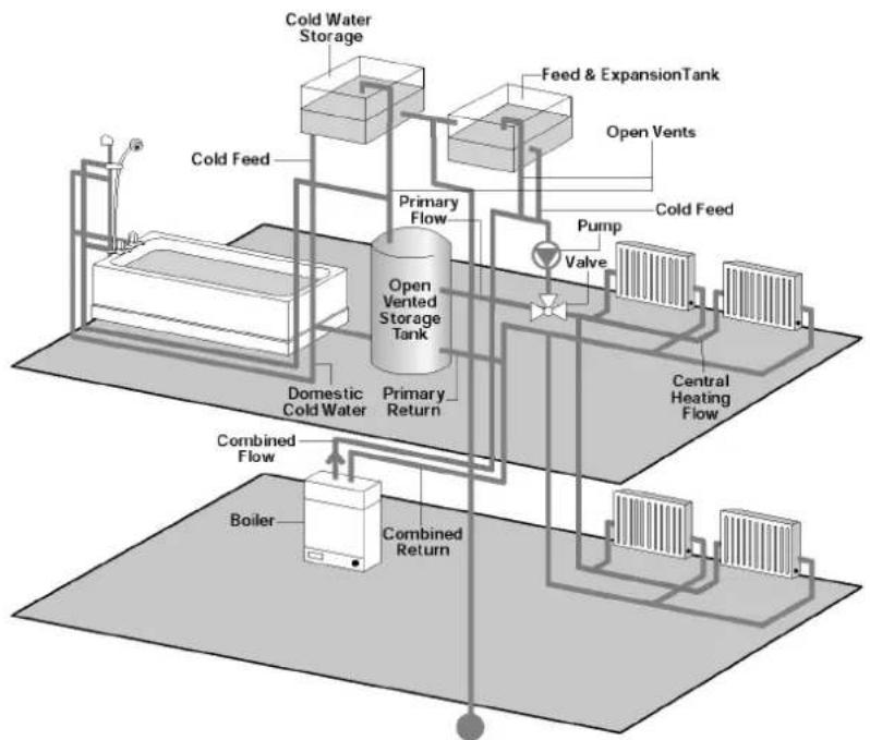
A typical traditional system with open vented hot water storage tank
Conventional Boilers
These are used in traditional central heating systems in the UK.
flowchart
graph TD
    A["Boiler"] --> B["Combined Return"]
    B --> C["Combined Flow"]
    C --> D["Domestic Cold Water"]
    D --> E["Primary Return"]
    E --> F["Open Vented Storage Tank"]
    F --> G["Feed & ExpansionTank"]
    G --> H["Open Vents"]
    H --> I["Pump"]
    I --> J["Valve"]
    J --> K["Cold Feed"]
    K --> L["Cold Water Storage"]
    L --> M["Cold Feed"]
    style A fill:#f9f,stroke:#333
    style B fill:#ccf,stroke:#333
    style C fill:#cfc,stroke:#333
    style D fill:#fcc,stroke:#333
    style E fill:#cff,stroke:#333
    style F fill:#ffc,stroke:#333
    style G fill:#fcc,stroke:#333
    style H fill:#ffc,stroke:#333
    style I fill:#fcc,stroke:#333
    style J fill:#fcc,stroke:#333
    style K fill:#fcc,stroke:#333
    style L fill:#cff,stroke:#333
    style M fill:#fcc,stroke:#333
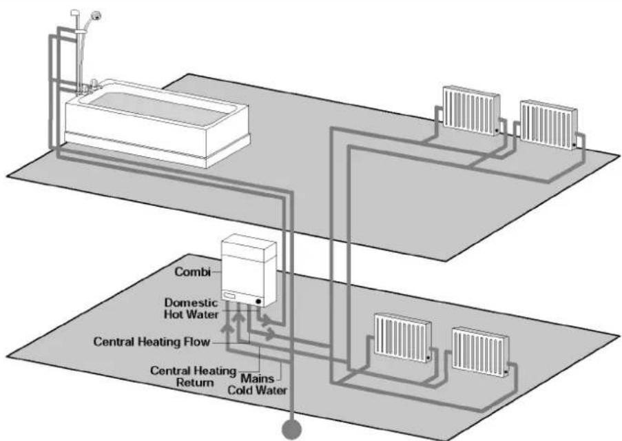
A typical COMBI system
Combination Boilers
With a combination boiler, hot water and central heating requirements are provided from the one unit.
flowchart
graph TD
    A["Refrigerator"] --> B["Combiner"]
    B --> C["Domestic Hot Water"]
    C --> D["Central Heating Flow"]
    D --> E["Central Heating Return"]
    D --> F["Mains Cold Water"]
    F --> G["Refrigerators"]
    style A fill:#f9f,stroke:#333
    style G fill:#bbf,stroke:#333
natural_image
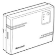
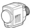
Line drawing of a Bosch mini device (no text or symbols on body)HC60NG Relay Module
The HC60NG Relay Module is an integral part of the CM Zone Control System. It is designed to control a Domestic Boiler, Valve, pump or Electric Heating appliances.
In the standard CM Zone Pack the HC60NG Relay Module is configured to control a Boiler based upon demand signals received from the HR80UK Radiator Controllers either directly or via a 'Y Plan' / 'S Plan' connection described below.
For control of other applications see Section 8: Changing the Configuration.

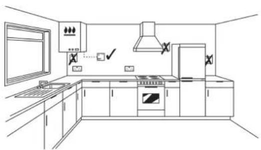
When selecting the operating site of the HC60NG ensure that the distance to other wireless devices such as wireless headphones, cordless phones etc. is at least 1-2m.

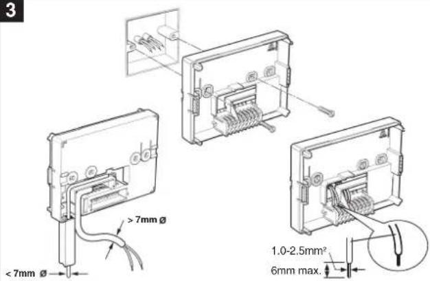
Please note: Maximum wire size 2.5mm ^2 . SPDT relay suitable for 24...230V\~, 10A resistive, 3A inductive
1
natural_image
Line drawing of a modern kitchen interior with appliances and fixtures (no text or symbols)The HC60NG is a radio frequency (RF) device and for the best performance should be installed in an open space. Leave at least 30cm distance from any metal objects including wall boxes and the boiler.
2
NOTE:
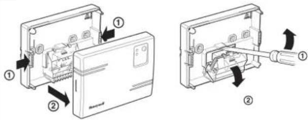
The HC60NG contains no user serviceable parts. It should be opened and installed by qualified installer only.
WARNING:
Electrostatic sensitive device! Do not touch the circuit board.
3
5
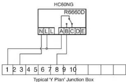
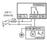
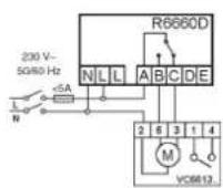
Honeywell 'Y Plan' Connections Honeywell 'S Plan'
NOTE:
For existing 'Y Plan' remove only Room Thermostat connections from Junction Box Terminals and replace with Connections to HC60NG.
4
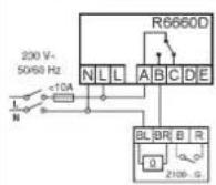
Typical Burner / Boiler connections
a. Burner (direct control)
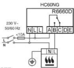
b. Combi boiler
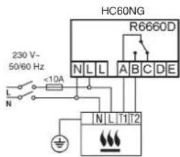
NOTE:
Install in accordance with local wiring regulations
CAUTION:
Observe ambient temperature and current limits (see HC60NG wiring label)
6
Innections
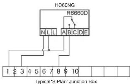
NOTE:
For existing 'S Plan' remove only Room Thermostat connections from Junction Box Terminals and replace with Connections to HC60NG.
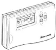
Section 5: CM67z Room Unit
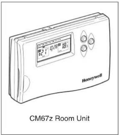
The CM67z Room Unit provides a central point from which to configure the system and set the time and temperature profiles for each Zone. At a given time, as defined within a Zone profile, the CM67z Room Unit transmits the required temperature setpoint to the respective HR80UK Radiator Controllers, local temperature control and override is then provided at each HR80UK Radiator Controller.
In the default setting, the CM67z Room Unit on-board sensor is disabled. This may be enabled for certain applications as described within Section 8: Changing the configuration
For normal operation refer to the CM Zone User Guide

When selecting the operating site of the CM67z ensure that the distance to other wireless devices such as wireless headphones, cordless phones etc. is at least 1-2m and at least 1m to other electrical devices. Do not mount the CM67z on metal surfaces or wall boxes.
Positioning
The CM67z is a RF device and for the best performance should be installed in an open space. Leave at least 30cm distance from any metal objects including wall boxes.
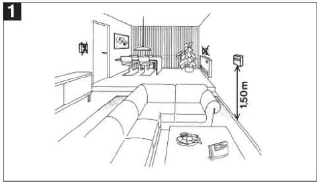
natural_image
Line drawing of a modern living room interior with sofa, coffee table, and wall-mounted TV (no text or symbols)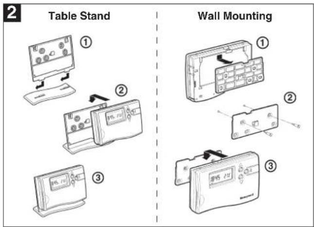
Start up
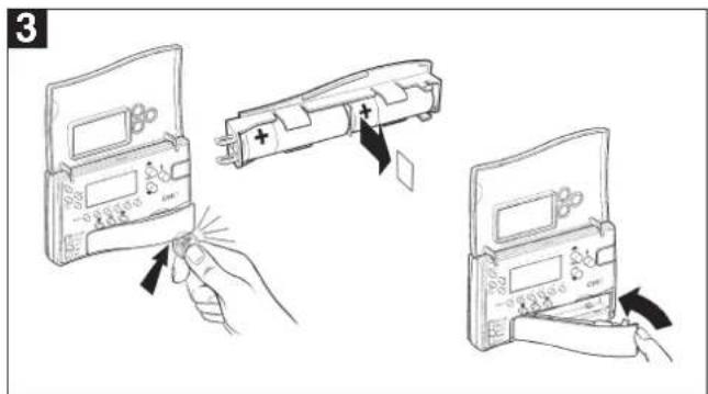
Remove the insulation tab from the CM67z battery compartment.
Setting the clock
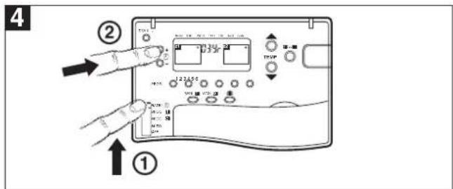
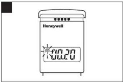
Move the CM67z slider to DATE/∅ position. When setting the date and time for the first time after batteries were inserted the zone controller display will flash as shown. Press the ⊕ or - buttons to set the current year (e.g. 03 = 2003).
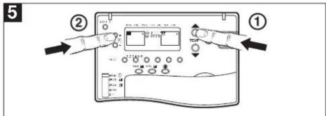
Press the TEMP ▲ button to go to the month: Press the ⏻ or - to set the current month (e.g. 01 = January). Press the TEMP ▲ button to go to the day of the month:
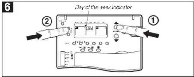
Press the Ⓐ or - to set the current day of the month. Check if the day marker on the display indicates the correct day of the week.
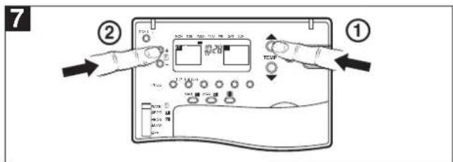
Press TEMP ▲ button to go to the time: Press the ⊕ or - until the correct time is displayed. Holding the button for a few seconds will change the time slowly then quickly.
natural_image
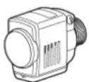
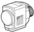
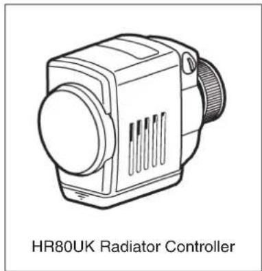
Line drawing of a HR80UK Radiator Controller device (no text or symbols on the device itself)The HR80UK Radiator Controller provides local room temperature control based upon setpoint information received from the CM67z Room Unit and sends Load Demand signals based upon room conditions to the HC60NG Relay Module. Setpoints can be temporarily overridden using the adjustment dial.
The HR80UK can be fitted onto Honeywell VT15, VT117, VT200 and many other manu - facturers TRV bodies with a M30x1.5mm thread and a 12.9 - 10.5 mm valve closing point, adaptors may be available for manufacturers with non standard connections. For more information contact Honeywell Technical Help Desk, details on the back page.

When selecting the operating site of the HR80UK ensure that the distance to other wireless devices such as wireless headphones, cordless phones etc. is at least 1-2m.
In the standard CM Zone Pack the HR80UK Radiator Controllers are pre-bound to each zone as indicated by the zone number label. To add additional HR80UK Radiator Controllers to a zone refer to Section 8: Changing the Configuration.
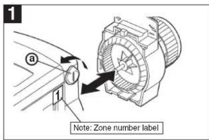
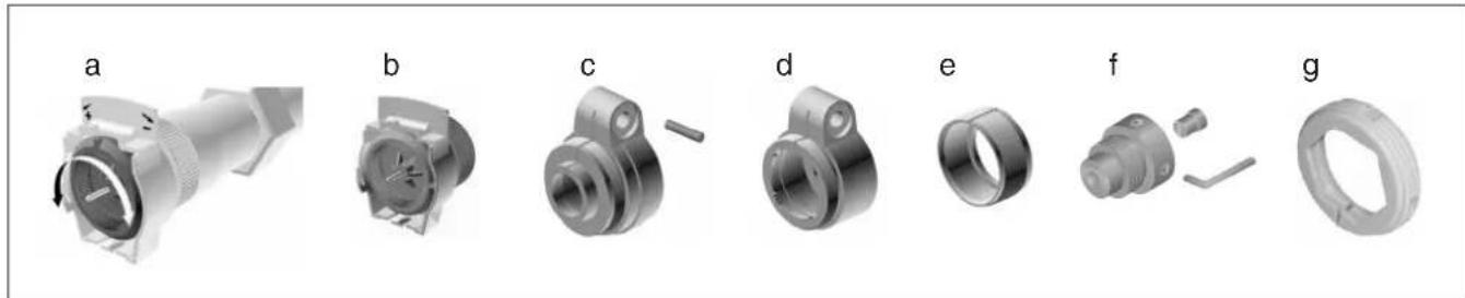
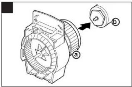
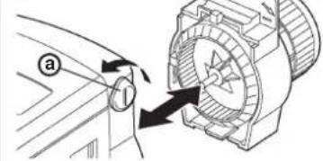
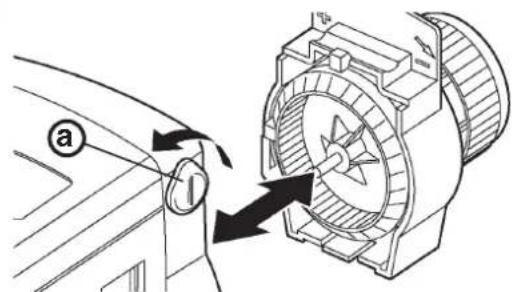
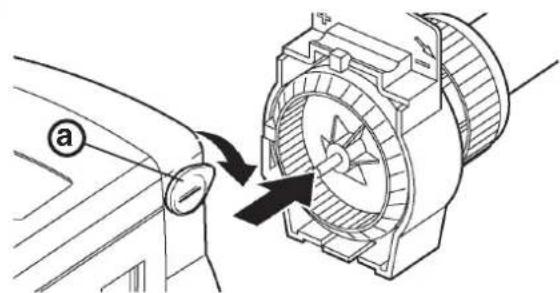
Turn the locking knob a and separate the operating module from the coupling module.

Turn the coupling module wheel ⓐ anticlockwise (approx. 3 rotations) until the nose ⓑ reaches the end stop Ⓒ.
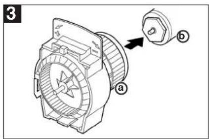
Fit the coupling module ⓐ to the TRV body ⓑ and tighten by hand.
For Adaptors see below.
natural_image
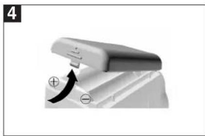
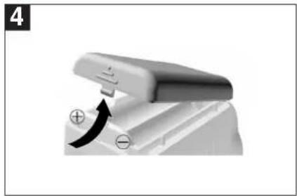
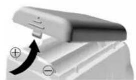
Close-up of a mechanical component with a curved arrow indicating motion or force (no text or symbols visible)Install batteries into the operating module.
Note: Check correct polarity.
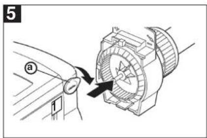
Fit the operating module onto the coupling module and turn the locking knob (a) down to lock in place.
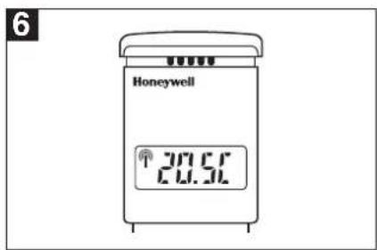
When adaption is complete the room temperature set-point is displayed.
A selection of adaptors are available to suit many other TRV manufacturers. For more information please contact Honeywell Technical Help Desk, details on the back page.

When selecting the operating site ensure that the distance to wireless devices such as wireless headphones, cordless phones etc. is approx. 1-2m.

It is recommended to complete the system testing before mounting the wall bracket on the wall. Position the CM67z Room Unit as close as possible to the location where it will be used.
flowchart
graph TD
A["Input Signal"] --> B["Wall"]
B --> C["Coating"]
C --> D["Wall"]
D --> E["Coating"]
E --> F["Wall"]
F --> G["Output Sensor"]
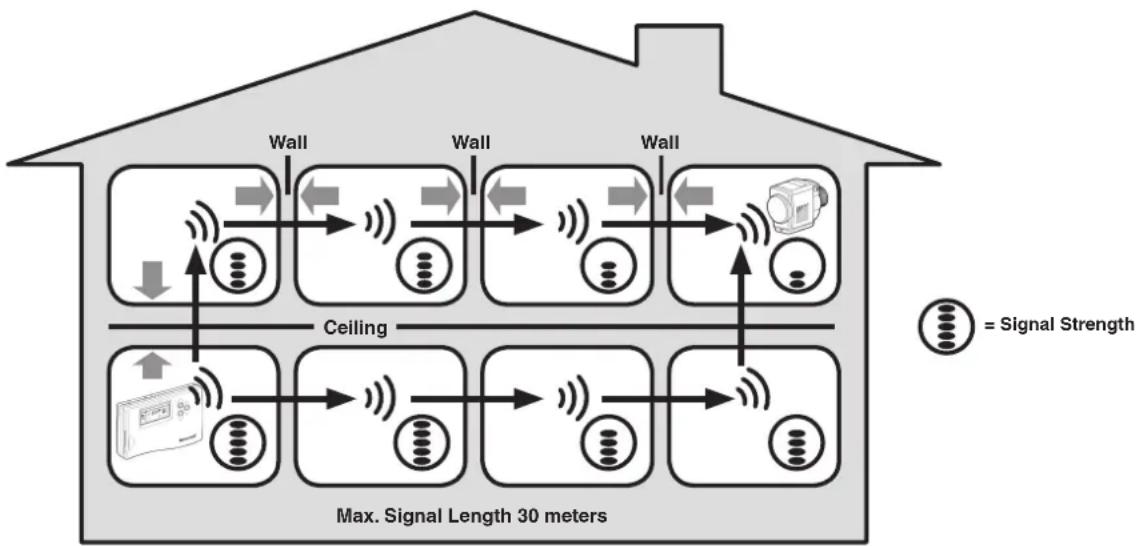
style A fill:#f9f,stroke:#333
style G fill:#bbf,stroke:#333
note right of A "Max. Signal Length 30 meters"
note right of G "= Signal Strength"
Typical example of Building Fabric Signal losses
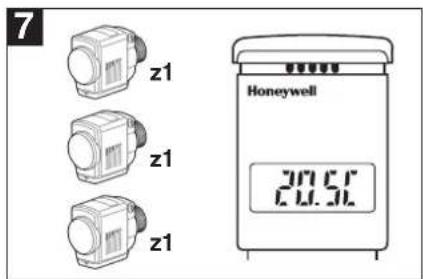
CM67z Room Unit to HR80UK Radiator Controllers
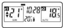
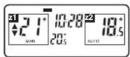
- Move the CM67z slider to AUTO position.
- Set the zone 1 setpoint to 5°C by pressing the TEMP button. Press the z1 button and set the zone 2 setpoint to 30°C by pressing the TEMP button.
- Check all the HR80UK's in zone 1 received 5°C setpoint and the ones in zone 2 30°C setpoint (allow 4 minutes for the HR80UK to receive the setpoint).
Repeat the steps 2 and 3 selecting different temperature values. - To complete the system test move the CM67z slider to the OFF position then back to the AUTO position. Install the wall bracket for the CM67z (if required).
HR80UK Radiator Controllers to HC60NG
- Move the CM67z slider to AUTO position.
- Set both zone 1 and zone 2 setpoints to 5°C by pressing the TEMP ▼ button (Using the 21-■ button to switch between zones).
- Set all HR80UK dials to the OFF position. Set the dial of the first HR80UK to the ON position. The green LED on the HC60NG should come on.
- Set the dial back to the OFF position and ensure that the green LED on the HC60NG boiler controller goes off.
- Repeat the steps 3 and 4 with all the HR80UK's in the system.
- To complete the system test reset all of the HR80UK radiator controllers back to normal operation by removing and re-inserting the batteries on each one. Install the wall bracket for the CM67z (if required).
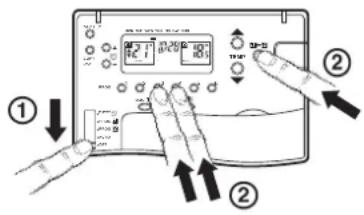
Test between CM67z & HR80UK
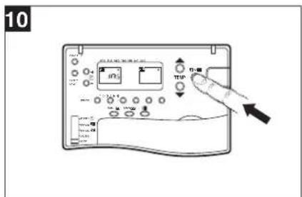
- CM67z room unit can send a test signal to the HR80UK radiator controllers and the HC60NG boiler or zone valve controller.
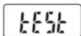
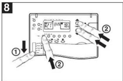
- Set the CM67z slider to the OFF position. Press the TEMP ▲▼ and PROG 2 buttons together to enter the test mode. The CM67z will display:
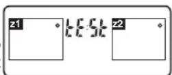
The first two digits in the HR80UK display indicate the number of received test messages, and the right-hand digit indicates the field strength (1 = sufficient field strength, 5 = very good field strength).
The red LED of the HC60NG indicates the field strength by means of flashing (1 = sufficient field strength, 5 = very good field strength).
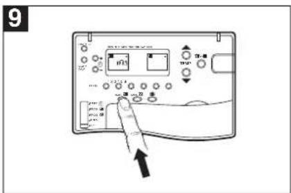
To deactivate Service mode:
Press the binding procedure button for 5 seconds or wait 5 minutes or remove and then re-insert the batteries.
The green LED on the HC60NG will flash once every 7 seconds.
7.1 Service mode
The wireless contact between the radiator controller, the central operating unit and a receiver unit is checked in Service mode. This mode is for installer use only.
Test between HR80UK & HC60NG
- Separate operating unit from coupling module (see Section 6)
- Turn the adjustment dial until on (open) appears in the display.
- Turn adjustment dial two full rotations (720°) further until tEST is displayed. Service mode is active.
The radiator controller transmits a test message to any available HC60NG.
The field strength is indicate by the number of flashes of the red LED (1 = sufficient field strength, 5 = very good field strength).
- Press the binding procedure button (page 8 - diagram 5).
The radiator controller is ready to receive the test message from the central operating unit.
8.1 Parameters of the CM67z Room Unit
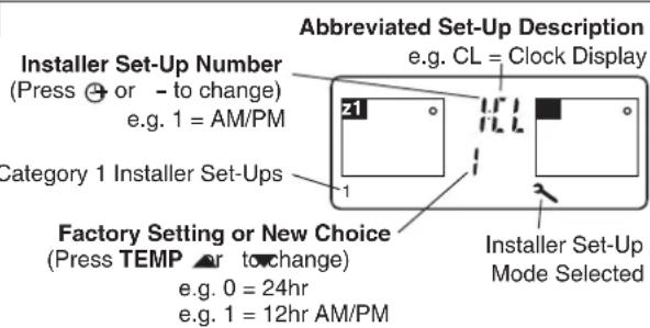
Installers Set Up Mode allows changing the controllers parameters to meet specific application requirements or customers needs. See fig 1 to 7 how to enter the Installer set-up.
1
Move the CM67z slider into the OFF position.
Press and hold the 21-■ and PROG 3 & 4 buttons together.
2
3
Press TEMP or to change factory setting
The display will flash indicating that a change has been made.
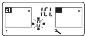
4
Press the z1 button to confirm the change is ok.
The display will stop flashing indicating that the new value has been stored.
5
Press ⏻ + or - to go to the next parameter and follow steps 3 & 4 to make changes.
6
Adjust other settings using the Installer Parameter List below.
7
To exit the Installers Set-Up Mode move the CM67z slider to the AUTO position.
Parameter list
| Parameter | Identifier | Range | Default | Category |
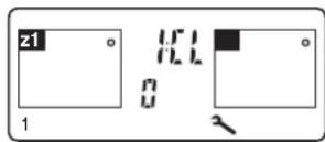
| AM-PM/24h select | 1:CL | 0 (24h) / 1(12h) | 0 (12h) | 1 |
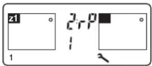
| Reset time/temp program | 2:rP | 0 (user prog) / 1 (factory prog) | 0 (user prog) | 1 |
| You must now press the PROG 2 key to enter the next section | ||||
| Minimum ON time | 3:Ot | 1 (1) 5 | 1 min | 2 |
| CM67 Room Unit Internal Temperature Sensor Enable | 6:tS | 0 (disabled)1 (enabled for display only)2 (enabled for display and control) | 0 (disabled) | 2 |
| Pump exercise feature enable | 7:PE | 0 (disabled) / 1 (enabled) | 0 (disabled) | |
| Cycle Rate | 8:Cr | {3,6,9} cph | 6 cph | 2 |
| System Timing Master | 9:Sn | 0 (disabled) / 1 (enabled) | 0 (disabled) | 2 |
| Upper Setpoint Limit | 10:UL | 21 (1) 30 | 30°C | 2 |
| Lower Setpoint Limit | 11:LL | 5 (1) 20 | 5°C | 2 |
| Temperature Offset | 12:tO | -3.0 (0.5) 3.0 | 0 K | 2 |
| Proportional Band Width | 14:Pb | 1.5 (0.5) 3.0 | 1.5K | 2 |
| Optimisation enable | 15:OP | 0 (disabled) / 1 (enabled) | 1 (enabled) | 2 |
| Loss of Communications Instruction | 16:LC | 0 (relay OFF) / 1 (relay ON 20%) | 0 (relay OFF) | 2 |
| CM67z built-in temperature sensor use | 17:SU | 0 (HR80UK enabled) / 1 (HC60NG enabled) / 2 (both HR80UK and HC60NG enabled) | 0 (HR80UK enabled) | 2 |
| HR80UK Window-Open Function | 18:Ho | 0 (disabled z1 & z2) / 1 (enabled z1only) / 2 (enabled z2 only) / 3 (enabled z1 & z2) | 0 (disabled z1 & z2) | 2 |
| HR80UK Local Override Function | 19:HL | 0 (disabled z1 & z2) / 1 (enabled z1only) / 2 (enabled z2 only) / 3 (enabled z1 & z2) | 3 (enabled z1 & z2) | 2 |
| Automatic Summer/Winter Time Changeover | 20:tC | 0 (disabled) / 1 (enabled) | 1 (enabled) | 2 |
| Reset Installer Mode Parameters to Defaults | 21:FS | 0 (modified) / 1 (factory) | 1 (factory) | 2 |
8.2 Adding further HR80UK Radiator Controllers
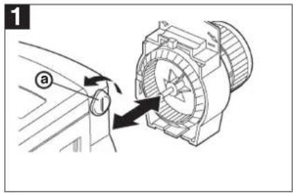
Turn the locking knob ⓐ and separate the operating unit and coupling module.
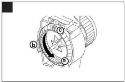
Turn the coupling module wheel ⓐ anti-clockwise (approx. 3 rotations) until the nose ⓑ reaches the end stop Ⓒ.
Fit the coupling module ⓐ to the TRV body ⓑ and tighten by hand.
For Adaptors see Section 6.
natural_image
Close-up of a mechanical component with a curved arrow indicating motion, no visible text or symbolsInstall batteries into the operating unit.
Note: Check correct polarity.
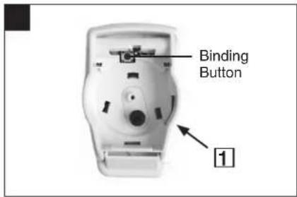
Attach the appropriate Zone Label and press the Binding Button.
Software version is displayed and the RF symbol 📋 flashes.
(Example Zone 1)
Repete for all additional HR80's to bind to this zone.
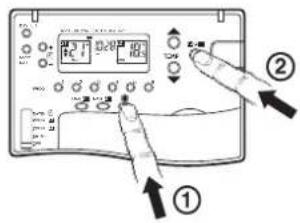
Enter CM67z Binding Mode
① Move slider to OFF position.
② Press and hold TEMP ▲, ▼ and PROG 1 buttons together.
Press MAN 21 button to select zone 1 or MAN 22 to select zone 2.
Press z1↔2 button to send the binding signal.
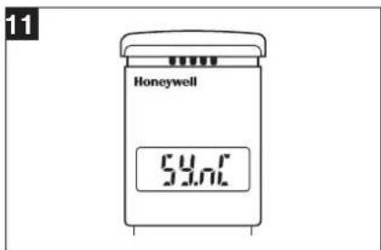
The HR80UK will display 59nC (with no RF symbol) during binding.
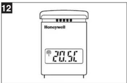
When complete the RF symbol will be displayed with the temperature setpoint (this can take up to 4 minutes).
8.2a Binding HR80UK Radiator Controllers to the HC60NG Boiler Module
13
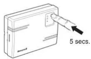
To put the HC60NG in the listening mode press the button on the HC60NG for 5 seconds (Red LED flashes 0.5 sec on/off).
14
Bind HR80UK Radiator Controllers to the Boiler Module :-
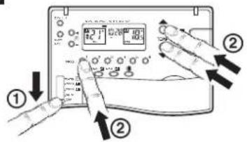
① Move slider to OFF Position.
② Press and hold Temp ▲, ▼ and
Prog 1 buttons together.
15
① Press the Holiday Button select Boiler Teach-in Mode.

② Press to send Binding Signal. With a successful teach-in the red LED will remain off (no longer flash).
8.3 Built -in sensor configuration
The CM67z Room Unit features a built-in temperature sensor used for specific applications. Sensor operation is defined by parameter 6:tS in Installer mode:
6:tS = 0 (Factory default. The built-in sensor is idle - not used for control nor measurement).
6:tS = 1 (The built-in sensor is used only for measuring the room temperature)
The symbol displayed next to the room temperature value indicates that the sensor is used for measurement only and the temperature in the room is controlled by the HR80UK Radiator Controller. Due to different locations of the CM67z Room Unit
and HR80UK Radiator Controller there may be a difference between the setpoint displayed by the CM67z Room Unit and the measured temperature value.
6:tS =2 (The built-in sensor is used to measure and control the room temperature in zone 1 or when a zone valve is used in zone 1) The CM67z Room Unit must be located in zone 1.
To complete the configuration you must set the 17:SU parameter to decide which system components will use the temperature value from the CM67z Room Unit:
17:SU = 0 - HR80UK's only (factory default)
17:SU = 1 - HC60NG (zone valve controller) only, HR80UK's will use their own built-in sensor.
17:SU = 2 - both HR80UK's and HC60NG.
8.4 Adding a HC60NG Zone valve controller
The HC60NG relay module can also be configured for controlling a zone valve. This is restricted to zone 1 only.
Before the binding procedure is started the following CM67z Room Unit parameters need to be set in order to control the zone 1 temperatures via the HC60NG as zone valve controller:
Enter the installer mode of the CM67z Room Unit and set the installer parameters: 6:tS =1, 9:Sn =1, 17:SU =1 or 2 (see Built-in sensor configuration).
a. Thermal actuator b. Zone valve c. Zone valve
NOTE:
Install in accordance with local wiring regulations
CAUTION:
Observe ambient temperature and current limits (see HC60NG wiring label)
Activating HC60NG Relay Module binding procedure
Press and hold the push button of the HC60NG Relay Module for 5 sec to enter the binding mode. The red LED will flash at 0.5 sec on/0.5 sec off.
Activate the binding procedure at the CM67z Room Unit as described in section 8.2 for zone 1. When binding information is received correctly the red LED of the zone valve controller will be switched off.
8.5 Resetting a Bound HR80UK
1
Turn the locking knob a and separate the operating unit and coupling module.
2
natural_image
Close-up of a white electronic device with a black curved arrow indicating rotation or force (no text or symbols visible)Lift battery cover and remove one of the batteries.
3
Press and hold the Binding Button while reinserting the battery.
Now follow steps 5 to 12 on page 8.
9.1 Trouble Shooting Guide
| Symptom (Fault Message) | Possible Cause | Remedy |
| During Binding | ||
| After binding procedure the symbol on HR80UK display is off. | Incorrect or incomplete binding procedure. Bad position of the CM67z during binding. | Repeat the binding procedure following the installation instructions.Repeat the binding procedure keeping approx. 1 m distance between CM67z and HR80UK. |
| After binding procedure the red LED of the HC60NG is on and the green one is flashing once every 3 sec. | Incorrect or incomplete binding procedure. Bad position of the CM67z during binding. | Repeat the binding procedure following the installation instructions.Repeat the binding procedure keeping approx. 1 m distance between CM67z and HC60NG. |
| After binding procedure the red LED of the HC60NG is on and green LED is flashing twice every 3 sec. | An attempt was made to bind more than 4 CM67z units to the HC60NG. | Press and hold the HC60NG push button for 15 sec to reset the memory. Repeat all the binding operations for this HC60NG making sure that no more than 4 CM67z units are bound. |
| After binding procedure the red LED of the HC60NG is on and green LED is flashing 3 times every 3 sec. | An attempt was made to cross bind the HC60NG with system timing message when no other binding was present. | Reset the HC60NG binding data by pressing the push button for 15 sec. Repeat the complete start up procedure as described in Section 8.2: Changing the Configuration. |
| After binding procedure the red LED of the HC60NG is on and green LED is flashing 4 times every 3 sec. | An attempt was made to bind two system timing messages to one HC60NG. | Make sure that only one CM67z is configured as system timing master. Reset the HC60NG binding data by pressing the push button for 15 sec. Repeat the complete start up procedure as described in Section 8.2: Changing the Configuration. |
| During Testing | ||
| HR80UK does not receive the correct setpoint from the CM67z. | Bad position of the CM67z.No binding data in the HR80UK.HR80UK bound to the wrong zone. | Reposition the CM67z and repeat the test.Repeat the binding procedure.Repeat the binding procedure, making sure that the HR80UK is bound to the proper zone. |
| The boiler does not switch on when the HR80UK setpoint is set to ON. | Missing binding data in the HC60NG. | Repeat the binding procedure (CM67z with the HC60NG boiler controller or HC60NG zone valve controller). |
| HC60NG's green LED is not flashing every 5 sec during the system test | Bad position of the CM67z. | Reposition the CM67z and repeat the test. |
| During Normal Operation | ||
| The red LED of the HC60NG is on. | The HC60NG receives no messages: RF signal is blocked (e.g due to bad position of the CM67z) or CM67z and HR80UK batteries are exhausted. | Return the CM67z room unit to the position where communications is reliable or replace discharged batteries. |
| The red LED of the HC60NG is flashing 2.5 sec on/2.5 sec off. | The HC60NG has not received signals from one (or more) transmitters in the system but still receives signals from other transmitters: RF signal is blocked (e.g due to bad position of the CM67z) or CM67z and HR80UK batteries are exhausted. | Return the CM67z room unit to the position where communications is reliable or replace discharged batteries. |
| The CM67z shows a different actual temperature than the HR80UK setpoint | Location of HR80UK and CM67z | Link the actual temperature measured by the CM67z with the HR80UK (only Zone 1 can be configured). |
| Blank display on CM67z or HR80UK. | No batteries.Wrong battery orientation.Improper battery compartment insertion (CM67z only).Exhausted batteries. | Check that the batteries are in the battery compartment and that the paper tab (CM67z only) has been pulled out.Check that the batteries have been installed in the correct orientation.Remove battery compartment and re-insert.Replace the batteries. |
| CM67z display shows a flashing battery symbol ( ) | Batteries need replacing. | Replace the batteries. |
| CM67z displays a spanner symbol ( ) | Fault in the CM67z room unit. | Remove and re-insert the battery compartment. If the spanner symbol ( ) does not clear itself in a few minutes call the Honeywell Technical Help-Desk, details on the back page. |
Section 9: Trouble Shooting (cont.)
9.1 Trouble Shooting Guide (cont.)
| Symptom (Fault Message) | Possible Cause | Remedy |
| During Normal Operation | ||
| CM67z display works but heating does not switch on:• The HC60NG LEDs are OFF• The HC60NG green LED is ON | No power to HC60NG.Bad electrical connection to the boiler or faulty boiler. | Check the power to the HC60NG is on.Check the boiler and HC60NG power supply as well as electrical connection between the boiler and HC60NG. |
| HC60NG red LED is constantly ON or flashing. | RF communication lost due to bad location of the CM67z room unit.RF communication fault. | Hook the room unit back on the wall bracket or return the room unit on the table stand to the position where communication was reliable.Call the Honeywell Technical Help-Desk, details on the back page.NOTE: The boiler can be controlled manually when RF communication is lost. Press the HC60NG push button to switch the boiler on or off.When the green LED is on - the boiler is on. |
| The HR80UK display is blank or shows bAtt. | HR80UK batteries exhausted. | Replace the HR80UK batteries following the guidelines in the HR80UK user instruction. |
| The ( ) symbol on the HR80UK is not displayed. | RF communication lost due to bad location of the CM67z room unit.RF communication fault. | Hook the room unit back on the wall bracket or return the room unit on the table stand to the position where communication was reliable.Call the Honeywell Technical Help-Desk, details on the back page. |
9.2 Manual adaption
Manual adaption can be used to solve various problems:
- if automatic adaption does not work.
- if the entire valve lift is to be utilized.
- if the radiator hardly gets warm at all.
- if the radiator does not become cold.
- if the E symbol is displayed (no adaption possible).
- if the [3] symbol is displayed (valve lift too short or motor cannot be moved).
9.3 Def (default setting) and Full operating modes
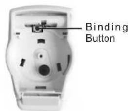
In order to change between the two operating modes, press the 'binding button' until the respective operating mode is shown on the display.
Binding Button
Def (default setting) operating mode
The HR 80 operates with the optimum valve lift that is required for room temperature control.
Full operating mode
If the complete valve lift is to be used or if the valve does not close completely, you have to set the HR 80 to the full operating mode.

The battery lifetime is reduced in the full operating mode.
9.4 Resetting the HR 80 to the factory settings
- Separate operating unit from the coupling module (Fig. 1).
- Remove the batteries.
- Insert the batteries again while keeping the binding procedure button pressed.
- Attach the operating unit to the coupling module (Fig. 2).
1
Turn the locking knob ① and separate the operating unit and coupling module.
2
Attach the operating unit to the coupling module and turn the locking knob ⓐ
Environmental Note:
This product has been designed with your environment in mind!
Please respect this by disposing of all packaging and used parts in an environmentally friendly manner.
Do not dispose of batteries with household waste. They must be returned in accordance with the local statutory requirements.
Warning:
This product and its associated documentation and packaging are protected by various intellectual property rights belonging to Honeywell Inc and its subsidiaries and existing under the laws of the UK and other countries. These intellectual and property rights may include patent applications, registered designs, unregistered designs, registered trade marks, unregistered trade marks and copyrights and also include the following UK registration rights:
UK patent application number 98062207.8
UK registered design numbers 2073334, 2073340 and 2073343.
Hereby, Honeywell, declares that this CM67z is in compliance with the essential requirements and other relevant provisions of Directive 1999/5/EC, 73/23EC and 89/336EC.
CE
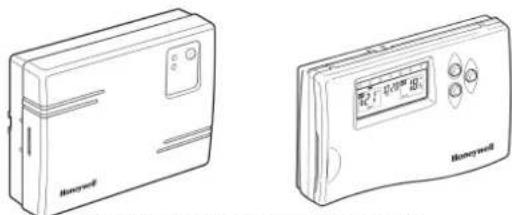
natural_image
Two line drawings of Honeywell devices, one with a labeled box and the other with a digital display (no text or symbols on the devices themselves)HC60NG Relay Module CM67z Room Unit
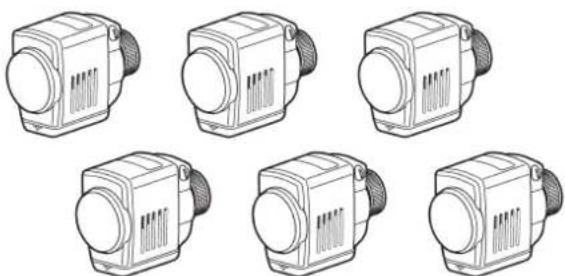
natural_image
Six identical line drawings of industrial heat exchangers or pumps, arranged in a 2x2 grid (no text or symbols visible)HR80UK Radiator Controllers
Useful References:
http://www.honeywelluk.com - Honeywell UK website
http://www.cm-zone.com/uk - CM Zone website
Technical Help-Desk: 08457 678999
Honeywell reserves the right to modify this document, product and functionality without notice.
This document replaces any previously issued instructions and is only applicable to the products described.
Note: This Product has been designed for applications as described within this document, for use outside of the scope as described herein refer to Honeywell for guidance. Honeywell cannot be held responsible for misapplication of the products described within this document
Honeywell
- Wireless Domestic Heating Zoning System
- INSTALLATION GUIDE
- TABLE OF CONTENTS
- Section Page
- GENERAL
- TECHNICAL INFORMATION
- Type numbers
- Material
- Dimensions
- Power
- Electrical wiring (only for HC60NG)
- Programming Capability
- Approvals
- Section 3: Factory Configuration
- Zoning Example
- A typical traditional system with open vented hot water storage tank
- Conventional Boilers
- A typical COMBI system
- Combination Boilers
- 1
- 2
- 3
- 5
- 4
- 6
- Section 5: CM67z Room Unit
- Positioning
- Start up
- Setting the clock
- CM67z Room Unit to HR80UK Radiator Controllers
- HR80UK Radiator Controllers to HC60NG
- Test between CM67z & HR80UK
- To deactivate Service mode:
- Service mode
- Test between HR80UK & HC60NG
- Parameters of the CM67z Room Unit
- 7
- Adding further HR80UK Radiator Controllers
- 8.2a Binding HR80UK Radiator Controllers to the HC60NG Boiler Module
- Built -in sensor configuration
- Adding a HC60NG Zone valve controller
- Activating HC60NG Relay Module binding procedure
- Resetting a Bound HR80UK
- Section 9: Trouble Shooting (cont.)
- Trouble Shooting Guide (cont.)
- Manual adaption
- Def (default setting) and Full operating modes
- Def (default setting) operating mode
- Full operating mode
- Resetting the HR 80 to the factory settings
- Environmental Note:
- Warning:
Brand : HONEYWELL
Model : YZ667A1060
Category : Temperature regulator