Mini Switch - Remote control toy Hobbico - Free user manual and instructions
Find the device manual for free Mini Switch Hobbico in PDF.


User questions about Mini Switch Hobbico
0 question about this device. Answer the ones you know or ask your own.
Ask a new question about this device
Download the instructions for your Remote control toy in PDF format for free! Find your manual Mini Switch - Hobbico and take your electronic device back in hand. On this page are published all the documents necessary for the use of your device. Mini Switch by Hobbico.
USER MANUAL Mini Switch Hobbico
natural_image
Two small propeller airplanes in flight, one labeled 'SWITCH', shown from different angles (no text or symbols on the aircraft body)SPECIFICATIONS
| Wingspan: high wing - 34 in [865 mm]low wing - 31 in [785 mm] | Wing Loading: 15.1–18.1 oz/sq ft [46–48 g/dm ^2 ] | Battery: 3S - 11.1V1300mAh LiPo |
| Wing Area: high - 195 in ^2 [12.6 dm ^2 ]low - 169 in ^2 [10.9 dm ^2 ] | Length: 32.5 in [825 mm]Weight: 20.4–21.2 oz [580–660 g] | Radio: 4 channel |
WARRANTY
Hobbico guarantees this kit to be free from defects in both material and workmanship at the date of purchase. This warranty does not cover any component parts damaged by use or modification. In no case shall Hobbico's liability exceed the original cost of the purchased kit. Further, Hobbico reserves the right to change or modify this warranty without notice.
In that Hobbico has no control over the final assembly or material used for final assembly, no liability shall be assumed nor accepted for any damage resulting from the use by the user of the final user-assembled product. By the act of using the user-assembled product, the user accepts all resulting liability.
If the buyer is not prepared to accept the liability associated with the use of this product, the buyer is advised to return
this kit immediately in new and unused condition to the place of purchase.
To make a warranty claim send the defective part or item to Hobby Services at the address below:
Hobby Services
3002 N. Apollo Dr. Suite 1
Champaign IL 61822 USA
Include a letter stating your name, return shipping address, as much contact information as possible (daytime telephone number, fax number, e-mail address), a detailed description of the problem and a photocopy of the purchase receipt. Upon receipt of the package the problem will be evaluated as quickly as possible.
READ THROUGH THIS MANUAL BEFORE STARTING CONSTRUCTION. IT CONTAINS IMPORTANT INSTRUCTIONS AND WARNINGS CONCERNING THE ASSEMBLY AND USE OF THIS MODEL.

text_image
Flyzone™ how high will you soarEntire Contents © 2013 Hobbico; Inc. FLZA3320 RTF FLZA3322 Tx-R
Champaign, Illinois (217) 398-8970
E-mail: airsupport@hobbico.com
TABLE OF CONTENTS
INTRODUCTION 2
AMA 2
SAFETY PRECAUTIONS 2
ADDITIONAL ITEMS REQUIRED .... 3
Radio Control System 3
Battery and Charger....3
CONTENTS 4
TOOLS REQUIRED 4
KIT INSPECTION....4
ORDERING REPLACEMENT PARTS 4
ASSEMBLE THE MODEL 5
Install the Tail Section 5
Setting Up the High Wing Configuration 6
Install the Propeller 7
CHANGING TO THE LOW WING CONFIGURATION ....8
GET THE MODEL READY TO FLY 9
Prepare the Transmitter and LiPo Battery .....9
Lithium Battery Handling & Usage 9
Check the Control Directions 10
Check the Balance (C.G.) 11
Balance the Model Laterally....12
PREFLIGHT 12
Identify Your Model....12
Balance Propellers....12
Range Check 12
MOTOR SAFETY PRECAUTIONS 12
AMA SAFETY CODE (excerpts)....13
General 13
Radio Control 13
CHECK LIST 13
FLYING....14
Takeoff 14
Flight 14
Landing 14
20A ESC INSTRUCTIONS....15
TACTIC TTX404 RADIO INSTRUCTIONS....17
INTRODUCTION
Thank you for purchasing the Mini Switch! Following the success of the larger, original Switch plane, the Mini Switch gives you two different fl ying experiences in one plane. The change from high wing confi guration to low wing confi guration requires only a screw driver and a few minutes. Both high and low wing confi gurations are very maneuverable and can satisfy the leisure pilot and the more sporty, aerobatic pilot. Should the model become damaged, repairs can be made quickly with regular CA glue.
For the latest technical updates or manual corrections to the Mini Switch visit the Hobbico web site at fl yzoneplanes.com. Open the "Airplanes" link, then select the Mini Switch. If there is new technical information or changes to this model a "tech notice" box will appear in the upper left corner of the page.
AMA
We urge you to join the AMA (Academy of Model Aeronautics) and a local R/C club. The AMA is the governing body of model aviation and membership is required to fly at AMA clubs. Though joining the AMA provides many benefits one of the primary reasons to join is liability protection. Coverage is not limited to flying at contests or on the club field. It even applies to flying at public demonstrations and air shows. Failure to comply with the Safety Code (excerpts printed in the back of the manual) may endanger insurance coverage. Additionally, training programs and instructors are available at AMA club sites to help you get started the right way. There are over 2,500 AMA chartered clubs across the country. Contact the AMA at the address or toll-free phone number below:
Academy of Model Aeronautics
5151 East Memorial Drive
Muncie, IN 47302-9252
Ph. (800) 435-9262
Fax (765) 741-0057
Or via the Internet at:
http://www.modelaircraft.org
http://www.modelaircraft.org/parkfl yer.aspx

text_image
AMA SINCE 1936IMPORTANT!!! Two of the most important things you can do to preserve the radio controlled aircraft hobby are to avoid fl ying near full-scale aircraft and avoid fl ying near or over groups of people.
SAFETY PRECAUTIONS
PROTECT YOUR MODEL, YOURSELF & OTHERS... FOLLOW THESE IMPORTANT SAFETY PRECAUTIONS
-
Your Mini Switch should not be considered a toy, but rather a sophisticated, working model that functions very much like a full-size airplane. Because of its performance capabilities, the Mini Switch, if not assembled and operated correctly, could possibly cause injury to yourself or spectators and damage to property.
-
You must assemble the model according to the instructions. Do not alter or modify the model, as doing so may result in an unsafe or unfl yable model. In a few cases the instructions may differ slightly from the photos. In those instances the written instructions should be considered as correct.
-
You must take time to build straight, true and strong.
- You must use an R/C radio system that is in fi rst-class condition, and a correctly sized motor and components throughout the building process.
- You must correctly install all R/C and other components so that the model operates correctly on the ground and in the air.
- You must check the operation of the model before every flight to ensure that all equipment is operating and that the model has remained structurally sound. Be sure to check clevises or other connectors often and replace them if they show any signs of wear or fatigue.
- If you are not an experienced pilot or have not flown this type of model before, we recommend that you get the assistance of an experienced pilot in your R/C club for your first lights. If you're not a member of a club, your local hobby shop has information about clubs in your area whose membership includes experienced pilots.
- While this kit has been flight tested to exceed normal use, if the plane will be used for extremely high stress flying, such as racing, or if a motor larger than one in the recommended range is used, the modeler is responsible for taking steps to reinforce the high stress points and/or substituting hardware more suitable for the increased stress.
We, as the kit manufacturer, provide you with a top quality, thoroughly tested kit and instructions, but ultimately the quality and fl yability of your fi nished model depends on how you build it; therefore, we cannot in any way guarantee the performance of your completed model, and no representations are expressed or implied as to the performance or safety of your completed model.
Remember: Take your time and follow the instructions to end up with a well-built model that is straight and true.
ADDITIONAL ITEMS REQUIRED
Radio Control System
The Mini Switch Tx-R (transmitter ready) comes with the servos and a Tactic™ TR624 receiver installed, so all that is required is a basic 4+channel transmitter. The Tactic TTX404 2.4GHz spread spectrum 4-channel radio control system (TACJ2404) is included with the RTF (ready to fly) version of the Mini Switch, so this same radio system will work for your Tx-R version, too.
○ Tactic TTX404 2.4GHz 4-channel system (TACJ2404)
○ (4) AA batteries will be required to operate the recommended transmitter (FUGP4304).
A more versatile transmitter is the Tactic TTX650 digital programmable transmitter. The TTX650 is loaded with features which will be useful with the Mini Switch such as a flight timer, dual rates, end-point adjustment, and exponential. Built-in mixes and user programmable mixes will accommodate your radio needs for future, more advanced models as well.
○ Tactic TTX650 2.4GHz 6-channel computer Tx only (TACJ2650)
If you already own a transmitter that you plan to use with the Mini Switch, fi rst make sure it is in the compatibility list at www.Tx-Ready.com/anylink-chart.html. If so, you can purchase the AnyLink 2.4GHz Universal Radio Adapter to allow your transmitter to communicate with the pre-installed Tactic receiver.
○ Tactic AnyLink® 2.4GHz Universal Radio Adapter (TACJ2000)
Tactic AnyLink SLT 2.4GHz Adapter Cable Futaba® Hitec® Round (TACM0003)
○ Tactic AnyLink SLT 2.4GHz Adapter Cable Hitec Aurora (TACM0004)
○ Tactic AnyLink SLT 2.4GHz Cable Spektrum® DX4e/5e/7s/8 (TACM0005)
○ Tactic AnyLink SLT Cable Fut 12Z/14MZ/18MZ/4YF 2.4GHz (TACM0007)
○ Tactic AnyLink SLT Cable Spek DX4e/5e/7s/8/10t/18/Deans (TACM0008)
○ Tactic AnyLink SLT Power Combo Spektrum DX4e 5e 18T Hit (TACM0015)
Battery and Charger
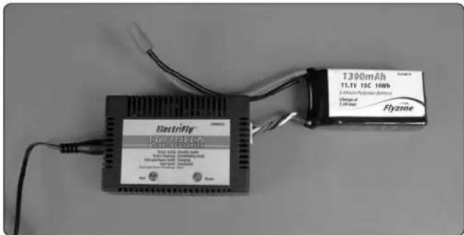
The Mini Switch RTF comes complete with a motor battery and charger. The Tx-R version requires a 1300 mAh 11.1V LiPo battery and LiPo Charger. The Mini Switch was designed for the Flyzone 1300mAh 11.1V LiPo battery (FLZA6014). Other LiPo batteries similar in size with the same voltage and capacity may also work, but they may not fit properly in the battery compartment or have the same type of battery connector. In addition to a battery, a LiPo battery charger is also required and there are several that will work (depending on your budget and requirements). A safe, economical charger is the ElectriFly® 3S (3-cell/11.1V) LiPo Smart Charger (GPMM3318). The Smart Charger includes adapters to charge from a 110V wall outlet or a 12V DC outlet from a car. The Smart Charger will take approximately 3-1/2 hours to fully charge the battery. The Smart Charger will time out after 2 hours and 40 minutes when charging the recommended battery. An additional hour on the charger will bring the capacity of the battery to near full. Some pilots prefer to have several batteries and charge them faster so they can fly more. For charging up to four batteries faster at the same time, the Great Planes PolyCharge4™ DC-powered LiPo charger (GPMM3015) is recommended. But unlike the Smart Charger, the PolyCharge4 does not have an internal LiPo cell balancer which is a critical component in making sure your LiPo batteries charge efficiently and evenly. So, for each LiPo battery you wish to charge simultaneously, one Great Planes Equinox™ LiPo Cell Balancer (GPMM3160) will also be required. Finally, the PolyCharge4 does not have AC capability, so if wall charging is a priority, a separate AC 12-Volt power source must also be purchased separately. A suitable power supply for the PolyCharge4 is the Great Planes 12V 12A DC power supply (GPMP0901).
CONTENTS
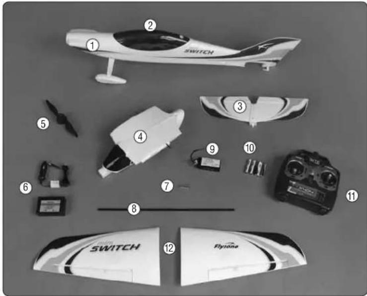
text_image
Labeled diagram of a small aircraft showing parts from the flight engine, including model numbers and accessories.- Fuselage
- Low-wing Canopy Hatch
- Horizontal Stabilizer
- High-wing Canopy Hatch
- Propeller Assembly
- 3S Smart Charger
- Screws
- Wing Joiner Tube
- 3S 11.1V 1300mAh LiPo
- AA Batteries
- TTX404 Transmitter
- Left & Right Wing Panels
NOTE: Transmitter, AA batteries, 3S 11.1V LiPo battery and 3S Smart Charger are not included in the Tx-R Mini Switch.
TOOLS REQUIRED
The Mini Switch requires only a screwdriver to finish assembly:
2 Phillips screw driver
KIT INSPECTION
Before starting to build, take an inventory of this kit to make sure it is complete, and inspect the parts to make sure they are of acceptable quality. If any parts are missing or are not of acceptable quality, or if you need assistance with assembly, contact Product Support. When reporting defective or missing parts, use the part names exactly as they are written in the Kit Contents list on this page.
Hobbico Product Support Ph: (217) 398-8970 ext. 5
3002 N Apollo Drive Suite 1 Fax: (217) 398-7721
Champaign, IL 61822
E-mail: airsupport@hobbico.com
ORDERING REPLACEMENT PARTS
Replacement parts for the Hobbico Mini Switch are available using the order numbers in the Replacement Parts List that follows. The fastest, most economical service can be provided by your hobby dealer or mail-order company. Parts may also be ordered directly from Hobby Services, but full retail prices and shipping and handling charges will apply. Illinois and Nevada residents will also be charged sales tax.
To locate a hobby dealer, visit the Hobbico web site at fl yzoneplanes.com. Choose "Find a Dealer" at the top of the page. Follow the instructions provided on the page to locate a U.S., Canadian or International dealer.
Parts may also be ordered directly from Hobby Services by calling (217) 398-0007, or via facsimile at (217) 398-7721,
but full retail prices and shipping and handling charges will apply. Illinois and Nevada residents will also be charged sales tax. If ordering via fax, include a Visa ^ or MasterCard ^ number and expiration date for payment.
Mail parts orders Hobby Services
and payments by 3002 N Apollo Drive, Suite 1
personal check to: Champaign IL 61822
Be certain to specify the order number exactly as listed in the Replacement Parts List. Payment by credit card or personal check only; no C.O.D.
If additional assistance is required for any reason contact Product Support by e-mail at productsupport@hobbico.com, or by telephone at (217) 398-8970.
REPLACEMENT PARTS LIST
| Order No. | Description |
| FLZA6355 | Wing Set Left & Right w/Decals |
| FLZA6356 | Fuselage w/Decals |
| FLZA6357 | Stabilizer & Elevator w/Tail Wheel |
| FLZA6358 | High Wing Canopy |
| FLZA6359 | Low Wing Canopy |
| FLZA6360 | Aluminum Landing Gear Assembly |
| FLZA6362 | Motor Mount Assembly |
| FLZA6364 | Spinner w/Propeller Adapter |
| FLZA6366 | Carbon Fiber Wing Tube |
| FLZA6367 | Canopy Mounting Screw |
| FLZA6368 | Pushrod & Control Horn Set |
| FLZA6369 | Low Wing Fuselage Foam Plugs |
| FLZA6365 | Battery Hatch Cover |
| FLZA6361 | Brushless Motor 28-30-1100kV |
| FLZA6363 | 20 Amp Electronic Speed Control |
| FLZA6370 | 8g Micro Servo |
| FLZA6371 | 8x6 Electric Propeller |
ASSEMBLE THE MODEL
Install the Tail Section
natural_image
Close-up of a hand holding a white plastic model airplane wing, with no visible text or symbols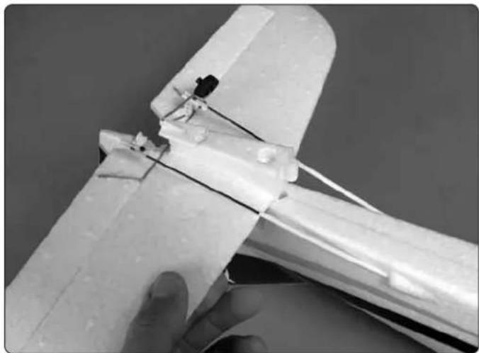
natural_image
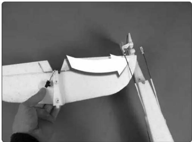
Close-up of a hand holding a white plastic mechanical component with wires and connectors (no visible text or symbols)☐ 1. Slide the horizontal stabilizer between the tail pushrods and the stabilizer pocket. You will need to slightly fl ex the pushrods in order get the stabilizer in position.
text_image
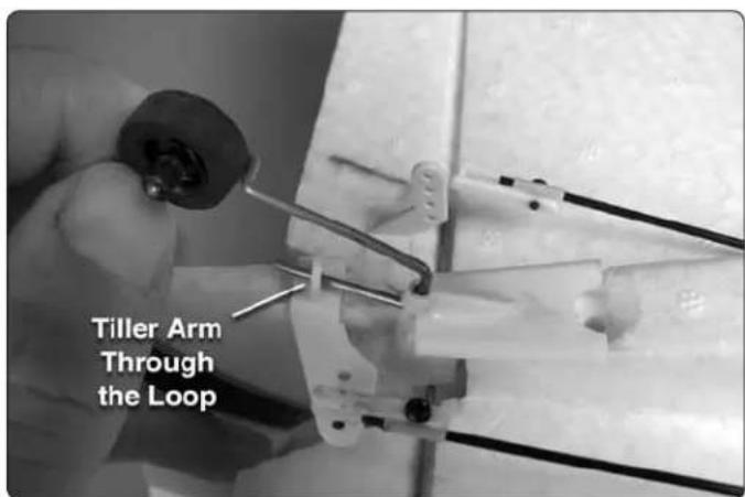
Tiller Arm Through the Loop☐ 2. When fi tting the horizontal stabilizer into the pocket guide the tail wheel tiller arm through the plastic hoop on the underside of the rudder.
natural_image
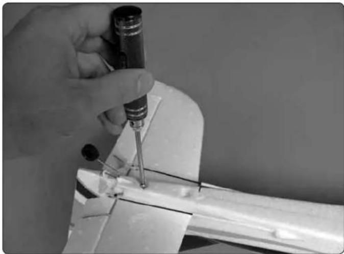
Close-up of a hand using a screwdriver to work on a metal component (no visible text or symbols)☐ 3. Use two 3 x 30 mm machine screws to secure the stabilizer in place.
Setting Up the High Wing Confi guration
We recommend fl ying the Mini Switch fi rst in the high wing confi guration. The high wing position will make the orientation of the airplane more visible at high altitudes.
natural_image
Close-up of a sewing machine needle stitching fabric (no visible text or symbols)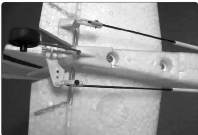
natural_image
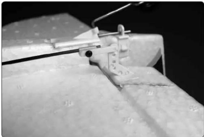
Mechanical assembly with metal rods and a black knob, mounted on a concrete base (no visible text or symbols)☐ 1. Connect the clevises on the pushrods to the outer holes in the elevator and rudder control horns. Squeeze the ends of the clevises to ensure they are snapped together properly.
natural_image
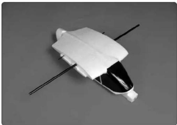
White plastic object with black lid and black rods, resembling a spacecraft or spacecraft (no text or symbols visible)☐ 2. Slide the carbon wing joiner through the tube in the high wing canopy hatch and center its position.
text_image
Tighten Outer Screws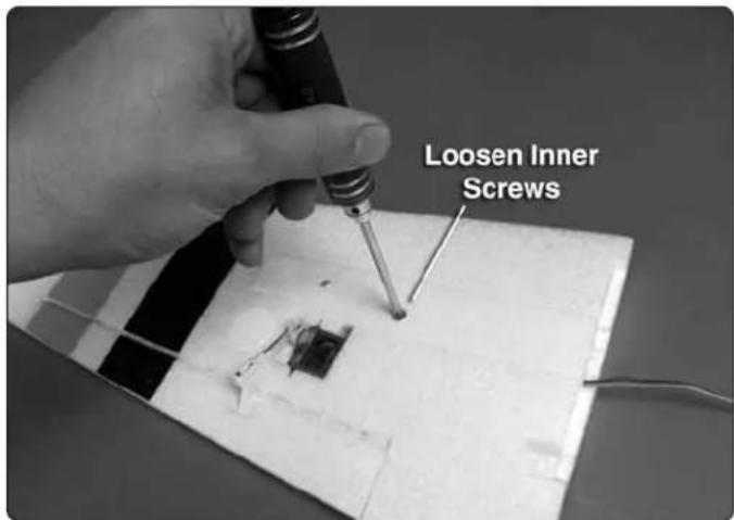
text_image
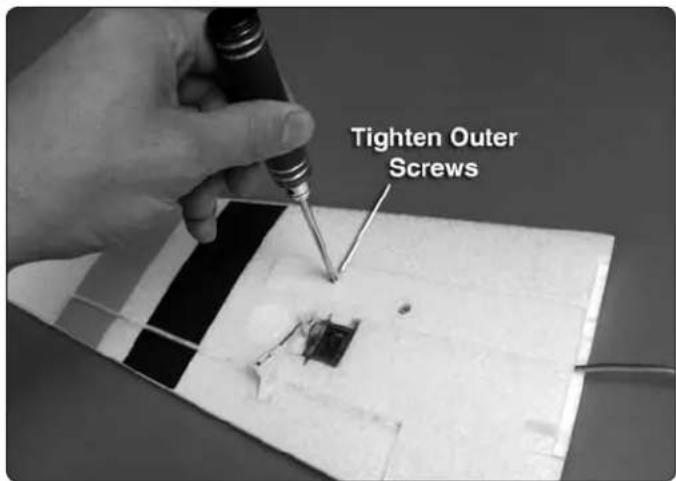
Loosen Inner Screws- Tighten the outer screws on the underside of the wing panels. Loosen the inner screws.
text_image
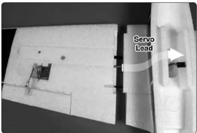
Servo Lead☐ 4. Install one of the wing panels onto the wing joiner tube. Feed the aileron servo lead through the hole in the center of the canopy hatch. The alignment pin fi ts into the small tube pre-glued in the wing. Push the joiner tube into the wing until it bottoms out against the outer screws in the wing panels.
natural_image
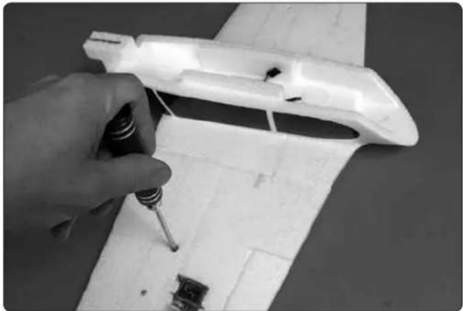
Close-up of a hand using a screwdriver to adjust or repair a white model airplane body (no text or symbols visible)- With both panels securely in place, tighten the inner screws in the wing panels. Pull on the wing panels to confirm they won't separate in flight.
text_image
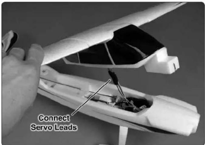
Connect Servo Leads- Attach the aileron servo leads to the Y-harness connected to the receiver. Ensure the orange wires in the servo leads align with the white wires in the Y-harness.
natural_image
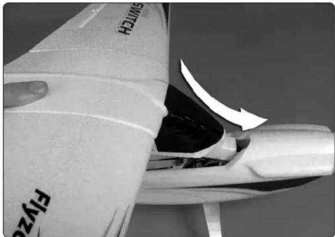
Close-up of a white aircraft fuselage with a curved arrow indicating motion or damage, no visible text or symbols.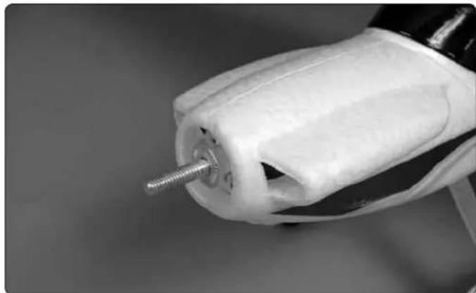
natural_image
Close-up of a white plastic mechanical component with a threaded screw, resting on a surface (no text or symbols visible)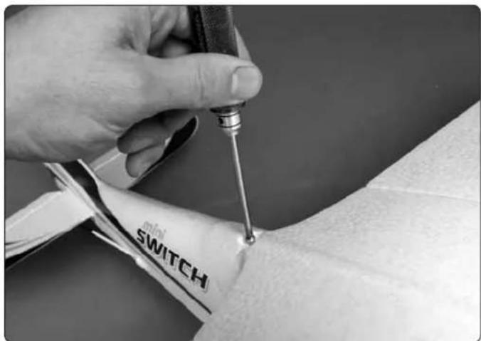
natural_image
Close-up of a hand using a medical tool to apply liquid onto a wrist with a 'SWITCH' label (no other text or symbols visible)☐ 2. Fit the prop adapter onto the motor shaft followed by the drive washer.
natural_image
Close-up of hands using a propeller to adjust a metal component (no visible text or symbols)- Test fit the canopy hatch onto the fuselage by inserting the tongue at the front of the hatch into the pocket in the fuselage and pressing the aft end of the hatch down in place. Secure the hatch using the included wing screw.
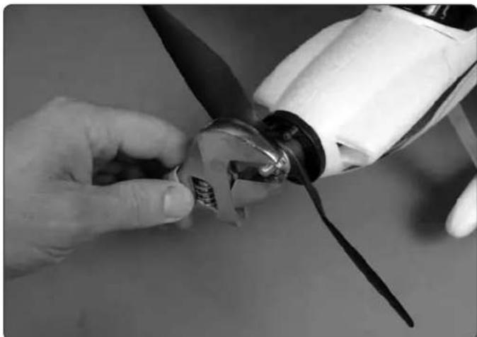
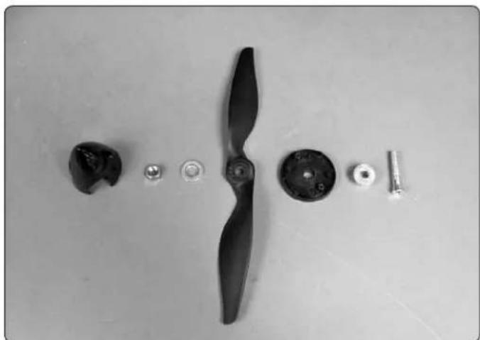
☐ 3. Install the spinner backplate onto the prop adapter followed by the propeller, prop washer, prop spacer, and prop nut. Tighten the prop nut thoroughly. If the spinner backplate contacts the foam fuselage after tightening the prop nut, loosen the nut and slide the prop assembly forward some. Then, re-tighten the nut.
Install the Propeller
natural_image
Black-and-white photo of a propeller with multiple small components arranged on a plain surface (no text or symbols visible)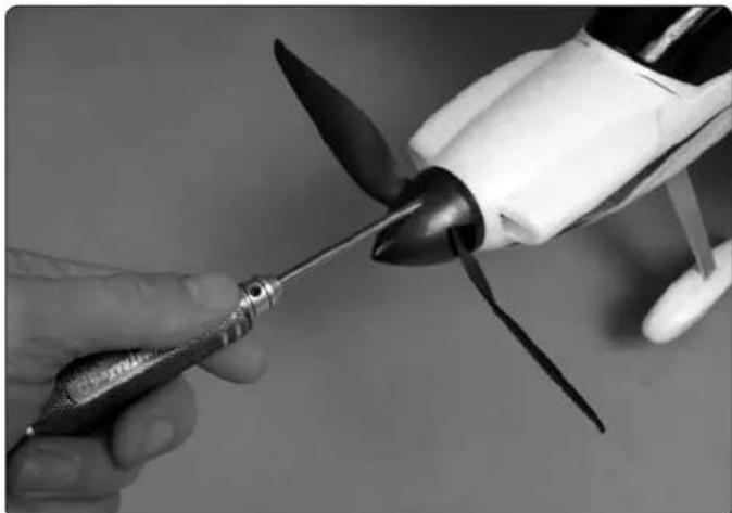
natural_image
Close-up of a hand using a tool to lift a propeller into a small boat-shaped motor (no text or symbols visible)☐ 1. Disassemble the spinner and prop adapter, making note of how it is installed. You will need to reassemble it onto the motor in the same order.
☐ 4. Tighten the spinner cone onto the assembly using the included screws.
natural_image
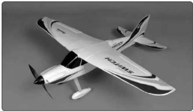
Model of a propeller airplane with visible propellers and fuselage markings (no text or symbols)- You have now completed the assembly of the high wing configuration of the Mini Switch!
CHANGING TO THE LOW WING CONFIGURATION
Once you are accustomed to fl ying the high wing confi guration, it's time to move the wings and give the low wing confi guration a try. You will fi nd that the lower wing position changes the aerobatic characteristics of the plane. In general, the low wing will perform most aerial maneuvers better than the high wing. You may fi nd the control response a little slower, but also smoother, than the high wing.
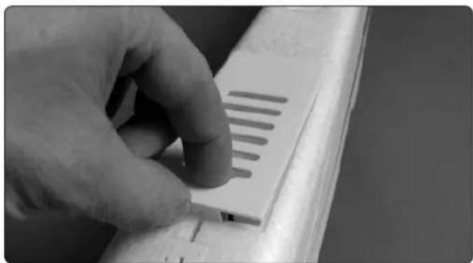
☐ 1. Remove the wing panels from the high wing configuration canopy hatch by disconnecting the aileron Y-harness, loosening the wing joiner screw and sliding the panels off of the joiner tube.
natural_image
Close-up of a hand holding a small white plastic component with parallel grooves, no visible text or symbols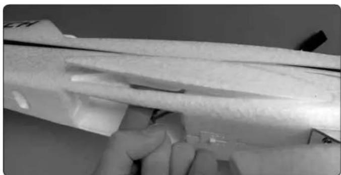
natural_image
Close-up of a hand holding a white plastic mechanical component with a cutaway view (no visible text or symbols)☐ 2. Remove the battery hatch by sliding the lever forward and lifting the hatch away. Push the wing pocket plugs out and set them aside for later use.
text_image
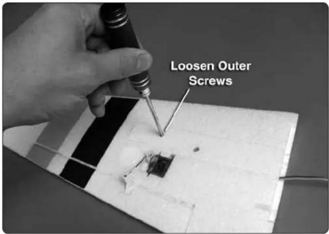
Loosen Outer Screws☐ 3. Loosen the outer wing screws three complete turns.
natural_image
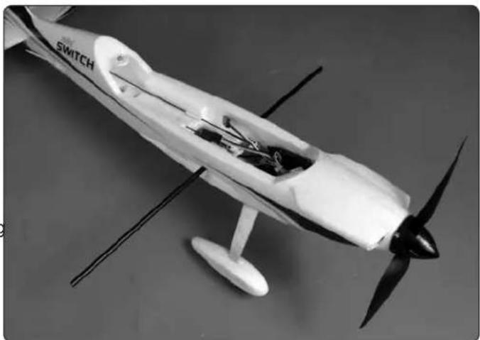
Black-and-white photo of a small white aircraft with propellers and visible internal components (no text or symbols)☐ 4. Insert the wing joiner tube through the joiner tube holes in the fuselage.
natural_image
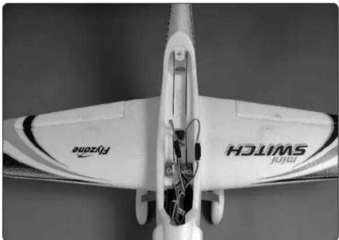
Top-down view of a white aircraft with visible propeller wings and branding, labeled 'SWITCH' and 'Flyzone', showing internal wiring (no text beyond labels)- Slide the wing panels onto the wing joiner. The aileron servo leads should fi t through the slots in the fuselage sides. Be sure the panels are fully seated against the fuselage inside the wing pockets. Tighten the inner wing screws against the wing joiner tube. Pull on the wing panels to confi rm they won't separate in fl ight.
natural_image
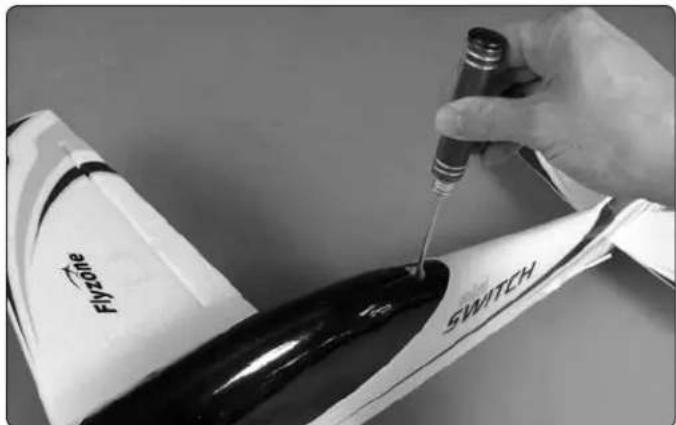
Close-up of a hand using a pipette to apply liquid onto a white aircraft body labeled 'SWITCH' (no additional text or symbols visible)- Connect the Y-harness to the aileron servo leads. Test fi t the low wing confi guration canopy hatch to the fuselage and screw it in place. NOTE: The low wing configuration will require you to readjust your control surface trims. Be prepared for this on your fi rst fl ight.
natural_image
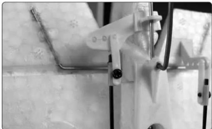
Close-up of mechanical components with metallic brackets and connectors, no visible text or symbols- Move the clevis to the innermost hole in the rudder control horn. The additional rudder movement will improve performance in the low wing confi guration. Be sure to move the clevis back to the outer hole if returning to the high wing confi guration.
GET THE MODEL READY TO FLY
Prepare the Transmitter and LiPo Battery
natural_image
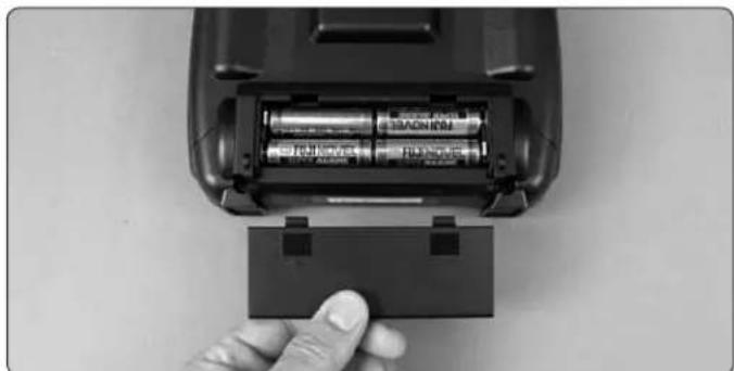
Hand inserting into a battery into an open cylindrical device (no visible text or symbols)☐ 1. Install fresh AA batteries into the transmitter. Follow the diagram molded inside the battery compartment.
☐ 2. Familiarize yourself with the charging procedure of the included LiPo battery. Read the charger manual completely.
text_image
Electricity T1.1V 15C 100h Lithium Polymer Battery Cleaner of 2.3Mpa Flyzone 1300mAh T1.1V 15C 100h Lithium Polymer Battery Cleaner of 2.3Mpa☐ 3. Fully charge the LiPo battery.
natural_image
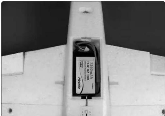
Close-up of a white aircraft fuselage with a black plastic box containing a battery and cable, no visible text or symbols.☐ 4. Test fi t the battery in the airplane. The battery wires should be tucked neatly along the side of the battery.
Lithium Battery Handling & Usage
WARNING!! Read the entire instruction sheet included with the battery. Failure to follow all instructions could cause permanent damage to the battery and its surroundings, and cause bodily harm!
● ONLY use a LiPo approved charger. NEVER use a NiCd/NiMH peak charger!
● NEVER charge in excess of 4.20V per cell.
● ONLY charge through the "charge" lead. NEVER charge through the "discharge" lead.
● NEVER charge at currents greater than 1C.
- ALWAYS set charger's output volts to match battery volts.
● ALWAYS charge in a fire proof location.
● NEVER trickle charge.
● NEVER allow battery temperature to exceed 150^ F ( 65^ C).
● NEVER disassemble or modify pack wiring in any way or puncture cells.
● NEVER discharge below 2.75V per cell.
● NEVER place on combustible materials or leave unattended during charge or discharge.
● ALWAYS KEEP OUT OF REACH OF CHILDREN.
Check the Control Directions
☐ 1. With the battery fully charged, turn on your transmitter and move the throttle stick (left stick) down to the idle position. Then, plug the motor battery into the ESC. If the ESC makes an erratic pattern of beeps after the initial startup beeps and a few seconds of silence, then it has entered programming mode and the throttle channel needs to be reversed on the transmitter, following Step 2. If not, skip Step 2. Take care around the propeller! The propeller will rotate when the throttle is advanced.
(Complete ESC programming instructions are included on page 15 of this manual)
☐ 3. View the model from behind and move the rudder control (left stick) on the transmitter to the left. The rudder should move to the left. If not, move the rudder reversing switch on the transmitter and then test the operation of the rudder again.
☐ 2. Disconnect the battery from the ESC. Then, move the throttle reversing switch on the transmitter. Confirm that the throttle stick is still in the idle position and reconnect the battery to the ESC.
4-CHANNEL RADIO SETUP (STANDARD MODE 2)
☐ 4. Moving the elevator control down (right stick) should cause the elevator to move up. Flip the elevator reversing switch on the transmitter if necessary.
FULL THROTTLE
ELEVATOR MOVES DOWN
☐ 5. Moving the aileron control to the right (right stick) should cause the left aileron to move down and the right aileron to move up. Flip the aileron reversing switch on the transmitter if necessary.
- When checking the propeller operation, BE SURE TO KEEP YOUR HANDS, CLOTHING, ETC. BEHIND THE SPINNING ARC OF THE PROPELLER! Operate the propeller outside, clear of any obstacles, and be sure that you have a fi rm grasp on the airplane before applying throttle.
OPERATING THE ESC
NECESSARY TRANSMITTER SETTINGS
If you are using a transmitter other than a Tactic transmitter, it's very important to set the transmitter's throttle channel adjustments, as follows:
- Set the throttle channel's travel adjustment (ATV,EPA or ATL) to 100%.
- Set the throttle trim and sub-trim to neutral or zero.
- Set the throttle channel's reversing switch to reverse on Futaba® transmitters. Other transmitters might require you to set the throttle reversing switch to normal.
LOW VOLTAGE CUT-OFF
The Mini Switch ESC includes a low-voltage cut-off feature that stops motor rotation if the battery's voltage drops too low. This protects the battery from damage due to under-voltage conditions. When the low voltage cut-off stops motor rotation it will still supply power to the receiver and all control surfaces except throttle, so you can maintain control of the aircraft.
NORMAL STARTUP PROCEDURE
- Unless calibrating the throttle or programming the ESC, always turn on the transmitter with the throttle stick all the way down. Turn on the transmitter.
- Connect the battery to the ESC. Listen for the three tones...“♪1 2 3 ” followed by three short beeps...“beep beep” beep” followed by one long beep...“beeeep”.
Now the ESC is "armed" and the model is ready to fly. The propeller will turn whenever the throttle stick is advanced, so use caution. When you are done running the motor or flying the plane simply disconnect the battery and turn off the transmitter.
Check the Control Throws
The Mini Switch is setup from the factory with the recommended control throws for the high wing configuration. If at any time you wish to return to the default control throws, or if you simply want to confirm the throws, use the following measurements:
NOTE: The throws are measured at the widest part of the elevators, rudder and ailerons.
These are the recommended control surface throws:
| ELEVATORUp & Down | 5/16" [8mm] 16 deg |
| RUDDERRight & Left | 1/4" [6mm] 8 deg |
| AILERONSUp & Down | 5/16" [8mm] 12 deg |
| ELEVATORUp & Down | 5/16" [8mm] 16 deg |
| RUDDERRight & Left | 3/8" [9.5mm] 12 deg |
| AILERONSUp & Down | 5/16" [8mm] 12 deg |
Check the Balance (C.G.)
More than any other factor, the C.G. (center of gravity/balance point) can have the greatest effect on how a model flies and could determine whether or not your first flight will be successful. If you value your model and wish to enjoy it for many lights, DO NOT OVERLOOK THIS IMPORTANT PROCEDURE. A model that is not properly balanced may be unstable and possibly unfl yable.
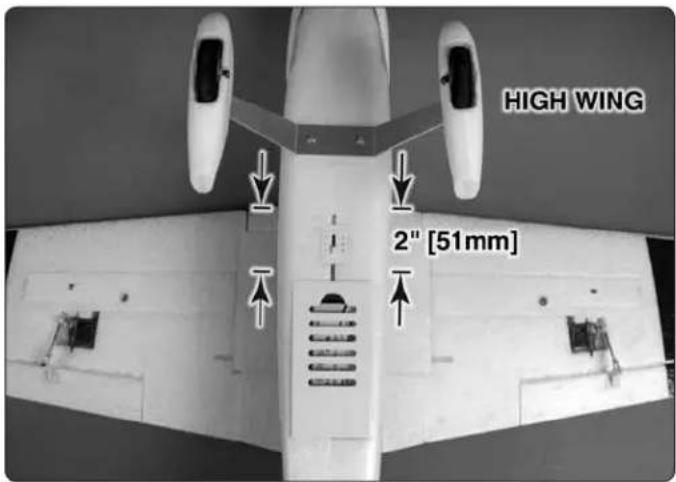
With the battery installed along with the propeller, spinner and hatch, the Mini Switch is designed to balance at the position shown without you needing to add any additional ballast to the nose or tail.
text_image
HIGH WING 2" [51mm]☐ 1. For the high wing version, apply narrow (1/16" [2mm]) strips of tape 2" [51mm] from the leading edge of each wing panel onto the underside of the wings as shown (you can also apply some masking tape and draw the lines with a felt-tip pen). If you are balancing the plane in the low wing confi guration, apply the strips of tape 2-11/16" [68mm] from the wing's leading edge on the top of the wings.
natural_image
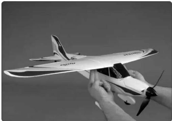
Black-and-white photo of a hand holding a small model airplane with propeller blades (no visible text or symbols)☐ 2. With the wings attached to the fuselage, all parts of the model installed (ready to fly) and the battery installed, lift the model with two fingers at the lines you made.
☐ 3. If the plane does not sit level with your fingers on the lines, you can shift them forward or aft 1/8" [3mm]. If the tail continues to drop even with your fingers 1/8" [3mm] aft of the lines, the model is "tail heavy". You will need to add weight to the nose. If the nose continues to drop even with your fingers all the way to the forward lines, the model is "nose heavy". You will need to move the receiver aft.
☐ 4. If you found it necessary to add weight or move the receiver, recheck the C.G. to confirm the plane now balances between the lines. Do not fly a plane that has not been properly balanced!
Balance the Model Laterally
☐ 1. With the wing level, have an assistant help you lift the model by the engine propeller shaft and the bottom of the fuse under the TE of the fi n. Do this several times.
☐ 2. If one wing always drops when you lift the model, it means that side is heavy. Balance the airplane by adding weight to the other wing tip. Stick-on lead weight can be purchased from your hobby supplier (GPMQ4485). An airplane that has been laterally balanced will track better in loops and other maneuvers.
PREFLIGHT
Identify Your Model
No matter if you fly at an AMA sanctioned R/C club site or if you fly somewhere on your own, you should always have your name, address, telephone number and AMA number on or inside your model. It is required at all AMA R/C club flying sites and AMA sanctioned flying events. Fill out the identification tag on page 24 and place it on or inside your model.
Balance Propellers
natural_image
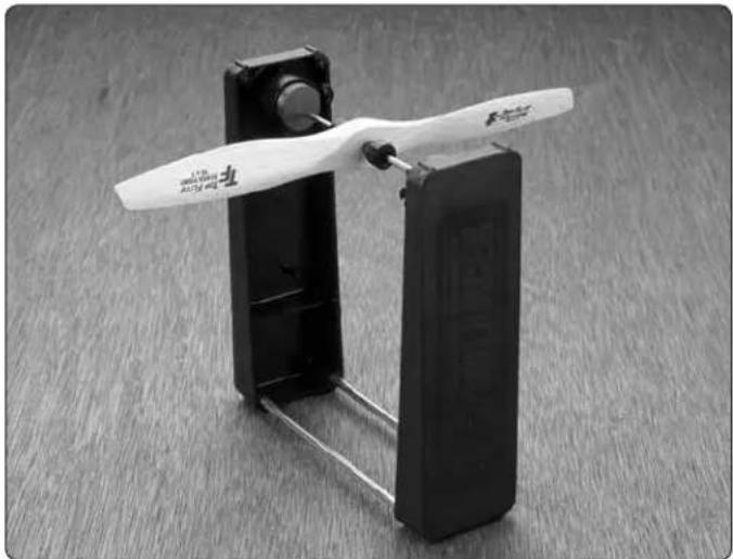
Black-and-white photo of a small propeller device with a white propeller, mounted on a black base against a wooden surface (no visible text or symbols)Carefully balance your propeller and spare propellers before you fly. An unbalanced prop can be the single most significant cause of vibration that can damage your model. Not only will motor mounting screws and bolts loosen, possibly with disastrous effect, but vibration may also damage your receiver and battery.
We use a Top Flite® Precision Magnetic Prop Balancer (TOPQ5700) in the workshop and keep a Great Planes® Fingertip Prop Balancer (GPMQ5000) in our flight box.
Range Check
The “range” is the safe operating distance from the transmitter to the receiver, and should be as far as you can clearly see the model. With the assistance of another person, place the aircraft on the ground and walk 100 feet (30m) away from the model. With the transmitter pointed directly at the model, operate the transmitter's controls, and ensure the movement of all surfaces is according to the movement of the transmitter.
MOTOR SAFETY PRECAUTIONS
Failure to follow these safety precautions may result in severe injury to yourself and others.
- Get help from an experienced pilot when learning to operate motors.
● Use safety glasses when starting or running motors. - Do not run the motor in an area of loose gravel or sand; the propeller may throw such material in your face or eyes.
- Keep your face and body as well as all spectators away from the plane of rotation of the propeller as you run the motor.
- Keep these items away from the prop: loose clothing, shirt sleeves, ties, scarfs, long hair or loose objects such as pencils or screwdrivers that may fall out of shirt or jacket pockets into the prop.
● The motor gets hot! Do not touch it during or right after operation.
- Do not throw anything into the propeller of a rotating motor.
AMA SAFETY CODE (EXCERPTS)
Read and abide by the following excerpts from the Academy of Model Aeronautics Safety Code. For the complete Safety Code refer to Model Aviation magazine, the AMA web site or the Code that came with your AMA license.
General
1) I will not fly my model aircraft in sanctioned events air shows, or model flying demonstrations until it has been proven to be airworthy by having been previously, successfully flight tested.
2) I will not fly my model aircraft higher than approximately 400 feet [120m] within 3 miles [4.8km] of an airport without notifying the airport operator. I will give right-of-way and avoid fly in the proximity of full-scale aircraft. Where necessary, an observer shall be utilized to supervise fly in the proximity of full-scale aircraft.
3) Where established, I will abide by the safety rules for the fl ying site I use, and I will not willfully and deliberately fly my models in a careless, reckless and/or dangerous manner.
5) I will not fly my model unless it is identified with my name and address or AMA number, on or in the model. Note: This does not apply to models while being fl own indoors.
7) I will not operate models with pyrotechnics (any device that explodes, burns, or propels a projectile of any kind).
Radio Control
1) I will have completed a successful radio equipment ground check before the first flight of a new or repaired model.
2) I will not fly my model aircraft in the presence spectators until I become a qualified flier, unless assisted by an experienced helper.
3) At all fl ying sites a straight or curved line(s) must be established in front of which all fl ying takes place with the other side for spectators. Only personnel involved with fl ying the aircraft are allowed at or in the front of the fl ight line. Intentional fl ying behind the fl ight line is prohibited.
4) I will operate my model using only radio control frequencies currently allowed by the Federal Communications Commission.
5) I will not knowingly operate my model within three miles of any pre-existing fl ying site except in accordance with the frequency sharing agreement listed [in the complete AMA Safety Code].
9) Under no circumstances may a pilot or other person touch a powered model in flight; nor should any part of the model other than the landing gear intentionally touch the ground, except while landing.
CHECK LIST
During the last few moments of preparation your mind may be elsewhere anticipating the excitement of the first light. Because of this, you may be more likely to overlook certain checks and procedures that should be performed before the model is flown. To help avoid this, a check list is provided to make sure these important areas are not overlooked. Many are covered in the instruction manual, so where appropriate, refer to the manual for complete instructions. Be sure to check the items off as they are completed (that's why it's called a check list!).
☐ 1. Check the C.G. according to the measurements provided in the manual.
☐ 2. Be certain the battery and receiver are securely installed in the fuse.
☐ 3. Balance your model laterally as explained in the instructions.
☐ 4. Confirm that all controls operate in the correct direction and the throws are set up according to the manual.
☐ 5. Make sure any servo extension cords you may have used do not interfere with other systems (servo arms, pushrods, etc.).
6. Balance your propeller (and spare propellers).
☐ 7. Tighten the propeller nut and spinner.
☐ 8. Place your name, address, AMA number and telephone number on or inside your model.
☐ 9. If you wish to photograph your model, do so before your first flight.
☐ 10. Range check your radio when you get to the flying field.
FLYING
CAUTION (THIS APPLIES TO ALL R/C AIRPLANES): If, while fl ying, you notice an alarming or unusual sound such as a low-pitched "buzz," this may indicate control surface fl utter. Flutter occurs when a control surface (such as an aileron or elevator) or a fl ying surface (such as a wing or stab) rapidly vibrates up and down (thus causing the noise). In extreme cases, if not detected immediately, fl utter can actually cause the control surface to detach or the fl ying surface to fail, thus causing loss of control followed by an impending crash. The best thing to do when fl utter is detected is to slow the model immediately by reducing power, then land as soon as safely possible. Identify which surface fl uttered (so the problem may be resolved) by checking all the servo grommets for deterioration or signs of vibration. Make certain all pushrod linkages are secure and free of play. If it fl uttered once, under similar circumstances it will probably fl utter again unless the problem is fixed. Some things which can cause fl utter are; Excessive hinge gap; Not mounting control horns solidly; Poor fi t of clevis pin in horn; Side-play of wire pushrods caused by large bends; Excessive free play in servo gears; Insecure servo mounting; and one of the most prevalent causes of fl utter; Flying an over-powered model at excessive speeds.
Takeoff
Before you get ready to takeoff, see how the model handles on the ground by doing a few practice runs at low speeds on the runway. Hold "up" elevator to keep the tail wheel on the ground. If necessary, adjust the tail wheel so the model will roll straight down the runway. If you need to calm your nerves before the maiden fl ight, shut the motor down and bring the model back into the pits. Top off the battery, then check all fasteners and control linkages for peace of mind.
Remember to takeoff into the wind. When you're ready, point the model straight down the runway, hold a bit of up elevator to keep the tail on the ground to maintain tail wheel steering, and then gradually advance the throttle. As the model gains speed decrease up elevator, allowing the tail to come off the ground. One of the most important things to remember with a tail dragger is to always be ready to apply right rudder to counteract motor torque. Gain as much speed as your runway and fl ying site will practically allow before gently applying up elevator, lifting the model into the air. At this moment it is likely that you will need to apply more right rudder to counteract motor torque. Be smooth on the elevator stick, allowing the model to establish a gentle climb to a safe altitude before turning into the traffic pattern.
Flight
For reassurance and to keep an eye on other traffic, it is a good idea to have an assistant on the flight line with you. Tell him to remind you to throttle back once the plane gets to a comfortable altitude. While full throttle is usually desirable for takeoff, most models fly more smoothly at reduced speeds.
Take it easy with the Mini Switch for the fi rst few fl ights, gradually getting acquainted with it as you gain confi dence. Adjust the trims to maintain straight and level fl ight. After fl ying around for a while, and while still at a safe altitude with plenty of battery charge, practice slow fl ight and execute practice landing approaches by reducing the throttle to see how the model handles at slower speeds. Add power to see how she climbs as well. Continue to fl y around, executing various maneuvers and making mental notes (or having your assistant write them down) of what trim or C.G. changes may be required to fi ne tune the model so it flies the way you like. Mind your fuel level, but use this fi rst fl ight to become familiar with your model before landing.
Landing
To initiate a landing approach, lower the throttle while on the downwind leg. Allow the nose of the model to pitch downward to gradually bleed off altitude. Continue to lose altitude, but maintain airspeed by keeping the nose down as you turn onto the crosswind leg. Make your final turn toward the runway (into the wind) keeping the nose down to maintain airspeed and control. Level the attitude when the model reaches the runway threshold, modulating the throttle as necessary to maintain your glide path and airspeed. If you are going to overshoot, smoothly advance the throttle (always ready on the right rudder to counteract torque) and climb out to make another attempt. When you're ready to make your landing fl are and the model is a foot or so off the deck, smoothly increase up elevator until it gently touches down. Once the model is on the runway and has lost fl ying speed, hold up elevator to place the tail on the ground, regaining tail wheel control.
One final note about flying your model. Have a goal or flight plan in mind for every flight. This can be learning a new maneuver(s), improving a maneuver(s) you already know, or learning how the model behaves in certain conditions (such as on high or low rates). This is not necessarily to improve your skills (though it is never a bad idea!), but more importantly so you do not surprise yourself by impulsively attempting a maneuver and suddenly finding that you've run out of time, altitude or airspeed. Every maneuver should be deliberate, not impulsive. For example, if you're going to do a loop, check your altitude, mind the wind direction (anticipating rudder corrections that will be required to maintain heading), remember to throttle back at the top, and make certain you are on the desired rates (high/low rates). A flight plan greatly reduces the chances of crashing your model just because of poor planning and impulsive moves. Remember to think.
Have a ball! But always stay in control and fly in a safe manner.
GOOD LUCK AND GREAT FLYING!
20A ESC INSTRUCTIONS
| SPECIFICATIONS | |
| Constant Current: | 20A |
| Burst Current (< 10 seconds): | 25A |
| BEC Mode: | Linear |
| BEC Output: | 5V, 2A |
| BEC Output Capability: | 5 servos |
| Battery Cell Count: | 2S – 3S LiPo, 5 – 9 cell NiMH |
| Weight: | 19g |
| Dimensions: | 42 x 25 x 8mm |
The ESC included with the Mini Switch is pre-programmed to the correct settings to work best with the Mini Switch—other than calibrating the throttle (only if using a transmitter different than the Tactic that comes with the Mini Switch), there is nothing that needs to be done with the ESC. However, should you ever desire to reprogram the ESC to suit different requirements, following are full programming instructions.
| FACTORY DEFAULT SETTINGS | |
| Motor Brake: | Off |
| Battery Type: | LiPo |
| LVC (Low-Voltage Cutoff): | Medium (3.15V/cell) |
| Start Mode: | Normal (.3 seconds) |
| Timing: | Low (3.75°) |
If using a transmitter different than the Tactic included with the RTF version, the throttle must be calibrated.
CAUTION: All adjustments to the ESC should be conducted with the propeller removed from the motor or one of the three motor wires disconnected from the ESC to prevent the motor from starting inadvertently.
- Turn on your transmitter and move the throttle stick to full-throttle.
- Connect the battery. The ESC will emit three rapid tones ("♪ 2 3") indicating that all is well, followed by two short beeps ("beep beep") indicating that the top point of the throttle range has been detected and set.
- You have about four seconds to return the throttle stick all the way down. Then the ESC will emit three more beeps (indicating the number of LiPo cells) followed by one long beep ("beeep") indicating that the low point of the throttle range has been detected. Simply disconnect the battery to end the procedure. Now the throttle has been calibrated and the Mini Switch is ready to fly.
FULL PROGRAMMING INSTRUCTIONS
- Access the Programming Menu:
A. Turn on the transmitter and advance the throttle stick all the way forward.
B. Connect the battery to the ESC.
Listen: Three tones ("1 2 3") two short beeps ("beep beep") a 5-second pause fi ve tones ("1 2 3 4 5")
Now the ESC is in the Programming Menu and will loop through a sequence of beeps, each of which represents a function in the menu that can be reprogrammed. (You don't have to do anything at this time; you can simply listen to the beeps identifying which function correlates with which sequence of beeps.)
| PROGRAMMING MENU | |
| FunctionSequence | |
| One short beep“beep” | Brake |
| Two short beeps“beep beep” | Battery type |
| Three short beeps“beep beep beep” | Cutoff mode* |
| Four short beeps“beep beep beep beep” | Cutoff Voltage |
| One long beep“beeep” | Start mode** |
| One long beep, one short beep“beeep beep” | Timing |
| One long beep, two short beeps“beeep beep beep” | Set the ESC to default |
| Two long beeps“beeep beeep” | Exit programming |
*Determines how the motor will stop when low-voltage is detected. Soft: Motor will quit gradually. Hard: Motor will cut immediately.
**Determines how the motor starts when you advance the throttle. Normal is recommended for airplane (fixed-wing) use. (Soft or super-soft is recommended for helicopters.)
- After you hear the sequence of beeps that represents the function you wish to change, lower the throttle stick to enter the programming mode for that function. The ESC will now beep as indicated below, waiting for your command to change the setting.
| Function | 1 Beep | 2 Beeps | 3 Beeps |
| Brake | Off | On | |
| Battery Type LiPo NiMH | |||
| Cutoff Mode Soft Hard | |||
| Cutoff Voltage Low | (2.85V) | Medium (3.15V) | High (3.3V) |
| Start Mode | Normal | Soft | Super Soft |
| Timing | Low (3.75°) | Medium (15°) | High (26.25°) |
After you hear the number of beeps (one beep, two beeps, three beeps) indicating the new setting you wish to use, advance the throttle again. Now you will hear the tones
("M 2 1 2") indicating that the value has been set and saved. If you immediately lower the throttle stick (within two seconds) you will exit programming mode proceeded by the three short beeps ("beep beep beep") counting the number of LiPo cells, followed by one long beep ("beeep") indicating that the model is ready to fly. Or, you can simply disconnect the battery at any time to exit programming mode.
If you leave the stick advanced, the programming mode will resume where it left off—simply listen for the sequence of beeps that represents the next function you wish to change, then lower the throttle stick again to enter the programming mode for that function.
Example
To set the motor brake from the factory default of "off" to "on":
- Advance the throttle stick. Turn on the transmitter.
- Connect the battery. Listen for the three tones (1 2 3") followed by two short beeps ("beep beep") followed by a 5-second pause followed by five tones (1 2 3 4 5"). The ESC is now in the Programming Menu.
- After you hear one short beep ("beep") indicating the motor brake function, lower the throttle stick.
- Listen for the beeps: one beep = brake off, two beeps = brake on. If you do nothing the ESC will simply loop through the sequence of beeps—once, then twice, then once, then twice, etc. waiting for your command to turn the brake on or off. To turn the brake on, advance the throttle stick after the two beeps. Listen for the tones ("1 2 1 2") indicating that the setting has been set and saved. If that's all you wanted to set, immediately lower the throttle stick (within two seconds) to exit programming mode, then hear three short beeps ("beep beep beep") followed by one long beep ("beep") indicating that the model is ready to fly.
Auto-Protection
The ESC features Auto-Protection to discontinue power to the motor under certain conditions:
- Start up failure: If the motor fails to start within 2 seconds of advancing the throttle the ESC will automatically cut power. To restart, lower the throttle stick, then advance again. This can happen if there is a poor connection between the ESC and motor or if the propeller or motor is impeded for any reason.
- Over-heat protection: If the ESC temperature ever rises to about 110 Celsius the ESC will automatically reduce power.
- Signal loss: Power to the motor will be reduced if the throttle signal is lost for 1 second. If the signal is lost for 2 seconds motor power will be cut completely.
| TROUBLESHOOTING GUIDE | |
| Problem | |
| Motor does not work, no tones or beeps are coming from the ESC. | The ESC is not receiving power from the battery. |
| Action Check the battery or plugs or change the plugs if the wires are damaged. | |
| Problem | |
| Motor does not work, Alert Tone sounds (“beep-beep,” “beep-beep,” “beep-beep,”...). | Battery Voltage is too high or too low. |
| Action Make sure the battery is charged and/or you are using the correct battery. | |
| Problem | |
| Motor does not work, Alert Tone sounds (long beeps: “beeeep-beeep-beeep...). | The ESC is receiving power from the battery, but is not receiving a signal from the receiver. |
| Action Make sure the transmitter is turned on and that the receiver is linked to the transmitter and receiving a signal. | |
| Problem | |
| Motor does not work, Alert Tone sounds (rapid beeps: “beepbeebeebeebeepeep...). | Throttle stick is not in the lowest position, or throttle needs to be calibrated. |
| Action Lower the throttle stick all the way, or recalibrate the throttle per calibration instructions. | |
| Problem | |
| Motor does not work, five tones are sounded (“1 2 3 4 5”) after the two beeps. | The direction of the throttle channel is reversed and the ESC has entered the Programming Menu. |
| Action Set the throttle direction the other way in the transmitter. | |
| Problem | |
| The motor turns the wrong direction. | The three motor wires are incorrectly connected to the ESC. |
| Action Swap any two of the motor/ESC wire connections with each other. | |
TACTIC TTX404 2 .4GHZ 4-CHANNEL SPREAD SPECTRUM RADIO INSTRUCTIONS
The Tactic TTX404 airplane radio system uses an advanced 2.4GHz spread spectrum technology to prevent unwanted outside interference from interrupting control of the model, ensuring error-free fl ying and eliminating the need to pull frequency pins before every fl ight. Tactic 2.4GHz transmitters and receivers are not compatible with other brands of 2.4GHz equipment.

For safe operation and best results, it's strongly recommended to read this manual in its entirety before use! Also read and understand the instructions included with the model. Damage resulting from misuse or modification will void your warranty.
FEATURES
text_image
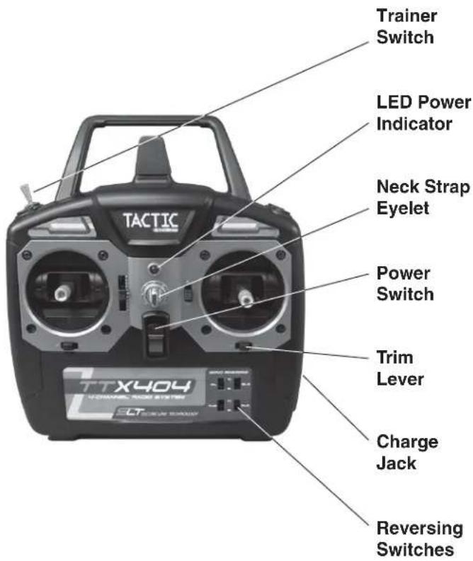
TACTIC TTX404 VOCORAC ROOM SYSTEM ELT Trainer Switch LED Power Indicator Neck Strap Eyelet Power Switch Trim Lever Charge Jack Reversing Switches● 2.4GHz spread spectrum technology
● Built-in failsafe & wireless trainer function
● Includes tiny, lightweight Tactic 6-channel receiver
● Analog & digital trims with servo reversing
● Transmitter binds to multiple Tactic 2.4GHz receivers
● Power status LED & built-in charge jack
TTX404 TRANSMITTER (Tx)
text_image
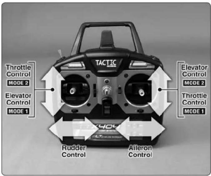
Throttle Control MODE 2 Elevator Control MODE 1 TACTIC Elevator Control MODE 2 Throttle Control MODE 1 Rudder Control Aileron ControlThe TTX404 airplane transmitter is available in either a "Mode 2" configuration with throttle on the left and elevator on the right, or "Mode 1" configuration with throttle on the right and elevator on the left. Mode 2 radios are most commonly used in the U.S., whereas Mode 1 radios are popular in other countries. Be sure the radio purchased is of the correct mode.
Four "AA" batteries are required to power the Tx (not included). Non-rechargeable 1.5V alkaline, or 1.2V rechargeable nickel-cadmium (NiCd) or nickel-metal hydride (NiMH) cells, can be used. Do not mix cell types, or old and new cells, etc. See the SERVOS AND ACCESSORIES section on page 16 for optional batteries available at local hobby retailers.
natural_image
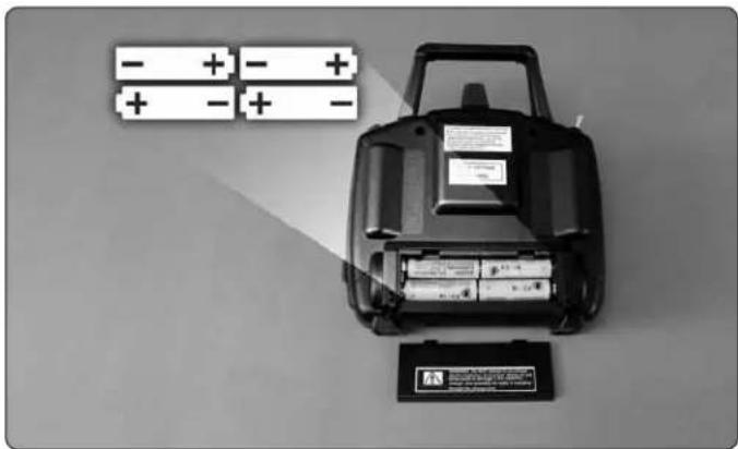
Black-and-white photo of a battery pack with two batteries and a battery stack, no visible text or symbols.To install the batteries, slide the battery door down. Insert the cells as shown in the diagram, making sure to note proper polarity for each cell. Close the battery door.
POWER SWITCH, LED, and LOW BATTERY ALARM
The red power LED should light when the power switch is moved upwards to the "ON" position. The Tx should have adequate power for flight when the LED is on constantly.
Anytime the LED begins to flash, accompanied by the sounding of an audible tone, the Tx battery voltage has dropped too low and operation of the model should NOT be attempted!

WARNING! Never operate an R/C model with weak Tx batteries! Reduced operational range and/or possible loss of control of the aircraft could result. Replace weak alkaline batteries, or re-charge NiCd or NiMH batteries before attempting a fl light!
If during a flight the Tx LED starts to flash, accompanied by the sounding of audible tones, it's a warning that the Tx batteries have become weak and the aircraft should be landed as soon as possible!
AILERON (CH1)
Controls the moveable surfaces at the end of both main wings to rotate the airplane about the "roll" axis (an imaginary line which extends from the airplane's nose to the tail). Since every airplane is different, the aileron reversing switch must be set so that moving the aileron stick to the right will cause the airplane's right aileron to deflect up, thus causing the right wing to drop and the airplane will bank to the right. Moving the aileron stick to the left will cause the airplane's left wing to drop and the airplane will bank to the left. This is one important method for turning the aircraft.
ELEVATOR (CH2)
Controls the moveable horizontal surfaces on the airplane's tail to rotate the airplane about the "pitch" axis (an imaginary line extending through the center of both main wings, from one wing tip to the other wing tip). Position the elevator reversing switch so that pulling the elevator stick back (towards you) will cause the elevators to deflect up, thus causing the nose of the airplane to rise. Pushing the elevator stick forwards (away from you) will cause the nose of the airplane to drop. When using the ailerons to bank the airplane's wings, pulling the elevator stick back will help the aircraft maintain altitude and turn the aircraft more quickly.
THROTTLE (CH3)
Controls the speed (R.P.M.) at which the engine or electric motor operates. With the throttle reversing switch in the NOR position, pulling the throttle stick back will cause the engine's speed to decrease. Pushing the throttle stick forward will cause the engine's speed to increase.
RUDDER (CH4)
Controls the sideways movement of the airplane's tail and will rotate the airplane about the "yaw axis" (an imaginary line from the top of the airplane's fuselage to the bottom of the fuselage, located near the center-point of the fuselage). Position the rudder reversing switch so that moving the rudder stick to the right causes the rudder to deflect to the right, thus causing the nose of the airplane to point to the right. Moving the rudder stick to the left will cause the nose of the airplane to turn left. When using the rudder in conjunction with the ailerons, the airplane's nose can point into a turn (instead of pointing up and "skidding" through the turn), allowing the airplane to perform tighter, more coordinated turns.
TRIMS
A “trim” lever is included for each of the main controls, located adjacent to the respective stick.
The aileron, elevator, and rudder trim levers are digital in function, and always rest at center position. Briefly deflecting the lever to either direction away from center will cause the respective servo output to finely rotate to one direction, and will be accompanied by an audible tone. Pressing and holding the trim lever will cause the servo output to move repeatedly. During a flight, when the main sticks are released and spring back to center position, the aircraft should ideally not veer in any direction. If the aircraft does veer in a particular direction, click the respective trim lever until the aircraft maintains a straight attitude on its own.
The throttle trim lever is analog in function, and can move mechanically up or down and rest at any point in the range. Moving the throttle trim lever slightly up or down will fi nely adjust the engine or motor at low speeds. For safety reasons, it's a good idea to use throttle trim when controlling the engine/motor at very low speed while on the ground. For aircraft with glow engines, the precise position of the trim lever is helpful when determining the engine's preferred idle point. The throttle trim lever is not active when the main throttle stick is above the center point.
REVERSING SWITCHES
Four reversing switches are built into the Tx, one for each control. Each switch can reverse the rotational direction of the servo that is connected to the respective channel. This is often a much easier method for changing the direction of a servo's movement as opposed to altering the mechanical connections between the model's surface and the servo. Refer to the model's instructions for specific details.
ADJUSTABLE STICKS
natural_image
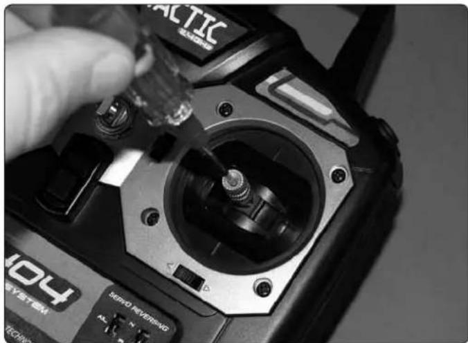
Close-up of a hand using a 3D ROCCDC 404 remote control console, showing mechanical components and wiring (no readable text or symbols)The length of both gimbal sticks can be adjusted as desired. Loosen the set screw inside the center of the stick with a 2mm hex wrench. Rotate the stick end counter-clockwise to lengthen the stick, or clockwise to shorten the stick. Once the desired stick length is found, tighten the set screw with the hex wrench.
CHARGE JACK

WARNING!! Do NOT attempt to recharge alkaline batteries! The charge jack should ONLY be used if rechargeable cells are used in the transmitter.
text_image
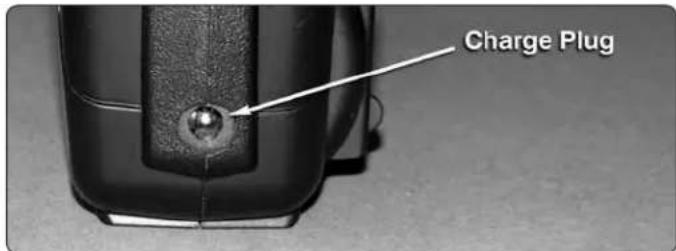
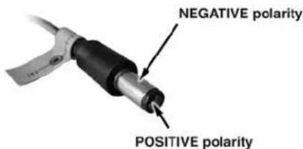
Charge PlugThe TTX404 includes a built-in charge jack for convenient recharging of NiCd or NiMH batteries, and is compatible with charge leads designed for Futaba® brand transmitters. (HCAP0101) This jack is NOT compatible with charge leads for Hitec®, Airtronics®, JR® or Spektrum® radios. The compatible charge plug is shown in the picture below.
text_image
NEGATIVE polarity POSITIVE polarityTo use the charge jack with optional rechargeable batteries, first remove the sticker that covers the charge jack on the
side of the Tx – making sure not to allow any object to be inserted inside the jack itself. Next, insert the cells inside the Tx's battery compartment noting proper polarity. Make sure the transmitter's power switch is in the OFF position. Connect a compatible charge lead to the jack and follow the instructions included with the charger for charging of NiCd or NiMH batteries that are rated at 4.8V.
Tactic's optional TACP1000 rechargeable battery and wall charger kit includes eight "AA" size rechargeable NiMH cells and 110V AC wall charger. It is compatible with this Tx and can be found at local retailers. Make sure to follow the instructions included with the charge kit.

WARNING!! It's not recommended to charge batteries at greater than 1 amp through this charge jack. Fast charging of NiCd and NiMH batteries should ONLY be done with chargers that are specifi cally designed to include the peak-detection function which can automatically stop charge when full charge is detected. Misuse, improper charging, or over-charging of rechargeable cells can result in damage to the cells that could include cell rupture, explosion, or fi re!!
TRAINER FUNCTION
The TTX404 Tx includes a built-in wireless trainer function – no trainer cable required! This trainer system connects a teacher's Tactic Tx to a student's Tactic Tx by wireless connection. Tactic's wireless trainer function is not compatible with trainer systems in any other brand radios.

IMPORTANT! Before attempting to fly the airplane, it's very important to make sure all reversing switches and trim lever adjustments on the student's Tx match the settings on the teacher's Tx! Otherwise, the airplane could suddenly veer off in an unwanted manner when the teacher's trainer switch is pressed. Proper matching of the student and teacher's Tx settings should ensure that no unexpected movements occur when the trainer switch is pressed. This is especially true of the throttle control!
-
The Tx that was used to setup the controls on the aircraft must be used by the TEACHER.
-
The student must use a separate Tactic Tx with wireless trainer function.
-
Place the teacher and student's transmitters within 1 meter of each other, and make sure the throttle stick for each Tx is set to idle.
-
Turn ON the power switch for the Tx being held by the student.
-
Pull and hold the trainer switch on the teacher's Tx, and then turn ON the teacher's Tx power switch.
-
The LED on the teacher's Tx will flash 3 times to indicate it has become bound with the student's Tx.
- The teacher can then release his trainer switch.
- Once both transmitters are bound together, power can be applied to the receiver to prepare for flight.
When the training session has ended, with the model on the ground and all power removed from the model, place both transmitters within 1 meter of each other and simply turn the power switch for both transmitters to the OFF position. This will terminate the wireless link between both transmitters. If additional training will be performed again, return to step 1 above to re-establish the wireless link between the teacher and student's transmitters.
TR624 RECEIVER & FLIGHT EQUIPMENT INSTALLATION (if applicable)
text_image
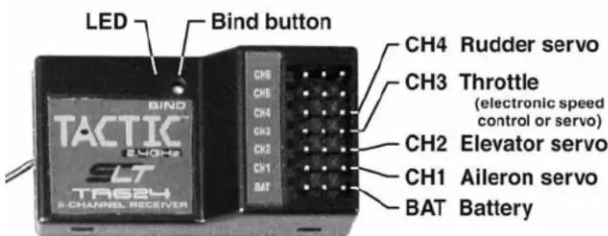
LED Bind button CH4 Rudder servo CH3 Throttle (electronic speed control or servo) CH2 Elevator servo CH1 Aileron servo BAT Battery BIND TACTIC SLT B-CHANNEL RECEIVERRECEIVER (Rx)
Mount the receiver as specified in the model's instructions. It's important to keep the Rx as far away from the engine/motor, servos, and ESC and other electronic items as possible. To prevent the Rx from becoming damaged, it might be acceptable to mount it inside certain models using Velcro®. In certain cases, wrapping the Rx with foam rubber can help to prevent damage from occurring due to vibration, but foam rubber can prevent adequate airflow from passing over the receiver in warm environments which might not be recommended. Additional Tactic TR624 receivers can be purchased from your local retailer (part number TACL0624) to work with this TTX404 transmitter.

IMPORTANT! Always make sure that power is applied to the transmitter BEFORE applying power to the receiver and servos, and that the throttle stick is at minimum (idle) position.
Failure to do so could result in the model becoming uncontrollable and cause a safety hazard.
BIND THE RECEIVER TO THE TRANSMITTER
For proper operation it's necessary to "bind" the Tx and Rx together electronically. This ensures sole communication between the two, and prevents other transmitters from being able to control the receiver.
- Turn on the Tx.
- Apply power to the Rx.
- If the Rx LED fl ashes once and then stays on, the Rx is already bound to the Tx and you can skip to the next section. Otherwise, insert a small diameter screwdriver through the hole marked "BIND" and press the pushbutton until the Rx LED glows red and then turns off after about one second.
- Release the "BIND" button.
- If the binding is successful, the Rx LED will flash once and then remain ON.
- Test for proper Tx/Rx functionality in the next section. If the radio doesn't appear to have become properly binded, repeat steps 1–6 above.
FAILSAFE FUNCTION
The included TR624 receiver has a failsafe feature which engages in the event that the radio signal from the transmitter somehow becomes interrupted. This safety feature causes the servos to automatically move either to a certain position, or hold their last position so to prevent the model from moving in an erratic manner. Channels 1, 2, and 4 will enter a "hold" mode, whereby the servos will lock in their last recognized position.
The servo connected to channel 3, normally being the throttle control, will move to a pre-set position. The factory default failsafe position for channel 3 is to move to 0% full throttle. Motor/prop movement should stop if the receiver loses signal from the transmitter. The throttle servo's failsafe position can be manually re-set to any other position if desired, as follows:
IMPORTANT NOTE: Before manually resetting the failsafe, make sure the servo reversing switches are in the correct position for the application.
- Apply power to the Tx and Rx.
2a. If using an ESC, do NOT arm the ESC. Do NOT attempt to adjust the throttle's failsafe position if the ESC is armed.
2b. If using a gas or glow powered engine, do NOT attempt to adjust the throttle's failsafe position while the engine is operating.
- Move the Tx throttle stick to the desired position for the throttle control to move if the Rx goes to failsafe.
- Press and hold the "Bind" button on the receiver, and the Rx's LED should blink twice. Release the Bind button, and the receiver's LED should turn on (stop fl ashing). The Tx and Rx should now be bound, with the throttle failsafe in the new position as set above.
NOTE: If you're using an ESC which has a signal loss feature, the pre-set failsafe position is irrelevant as the signal loss feature will cease the throttle operation if the signal is lost.
SYSTEM CHECK AND OPERATION

WARNING! During all pre-flight preparations with the aircraft on the ground, make sure the throttle stick remains at the minimum position and do not stand the Tx upright on the ground. Carefully lay the Tx on its back on the ground to prevent it from falling over and possibly dislodging the throttle stick from the low position which would create a safety hazard. Make sure all devices are properly mounted inside the model, and all wiring connections are solid to prevent them from easily becoming dislodged during normal flight. It's best to check the system with the propeller removed from the aircraft.
- Once all connections are made, check the general operation of the radio and all other components before attempting a flight.
- Move the Tx throttle stick to the minimum (idle) position.
- Turn on the Tx, and then the Rx.
- Make sure all controls are operating in the proper direction. If any servo is turning in the wrong direction, change the position of the reversing switch for that particular channel.
- With both sticks at center position, move the trim levers for the aileron, elevator, and rudder channels so each respective control surface is perfectly aligned with the main surface. For example: When the aileron trim lever is in the center position, it's best that the trailing edge of the aileron is aligned with the trailing edge of the wing itself (not above or below the wing's trailing edge).
- Make sure that movements of the throttle stick result in an equal adjustment of the throttle in the model. Depending on whether the airplane is electric or glow powered:
a. Electric: confi rm that when the throttle stick is at maximum position the electronic speed control gives the appropriate indications (LED and/or audible indicators) for full forward flight. And, when the throttle stick is at minimum position the electronic speed control gives the appropriate indications for "off" or no motor rotation.
b. Glow: confi rm that when the throttle stick is at maximum position the mechanical linkage to the engine allows the engine to be at full throttle. And, when the throttle stick is at minimum position and the throttle trim lever is moved to minimum position, the engine stops completely.
- Perform a “range check.” The “range” is the safe operating distance from the Tx to the Rx, and should be as far as you can clearly see the model. With the assistance of another person, place the aircraft on the ground and walk 100 feet (30m) away from the model. With the Tx pointed directly at the model, operate the transmitter’s controls, and ensure the movement of all surfaces is according to the movement of the transmitter.
- Anytime power is to be removed from the radio system, it's important to shut down power in the aircraft first. Otherwise, the aircraft could become out of control and cause a safety hazard! Move the throttle stick and throttle trim lever to minimum position to stop the glow engine or shut down the ESC. Once the propeller has stopped rotating, shut off the ON/OFF power switch in the model, and disconnect the power battery from the ESC in electric airplanes. Then turn off the power switch in the Tx.
SPECIFICATIONS
| TTX404 4-Channel Transmitter | |
| Channels 4 | |
| Frequencies | 2.403 – 2.480 GHz |
| Modulation | FHSS spread spectrum |
| Input power | Four “AA” alkaline, NiCd, or NiMH cells (3.8 – 8.0V, not included) |
| Output power < | 0.1W |
| Power indicators LED, with low voltage alarm | |
| Reversing switches | Slide switches all channels |
| Trims | Analog for throttle, digital for aileron, elevator, rudder |
| Antenna | Built-in non-removable |
| Charge jack | Built-in (Futaba® compatible, for use with optional NiCd or NiMH cells) |
| Trainer function | Wireless (compatible with Tactic brand transmitters only) |
| Optional mixes E | evon, V-Tail |
| Tactic TR624 Receiver | |
| Channels 6 | |
| Frequencies | 2.403 – 2.480 GHz |
| Modulation | FHSS spread spectrum |
| Input power | Four “AA” alkaline, NiCd or NiMH cells (4.0 – 6.0V, not included) |
| Failsafe | Programmable throttle, all other channels maintain last recognized positions |
| Dimensions | 1.77 × 0.98 × 0.5" (45 × 25 × 13mm) |
| Weight | 0.28 oz (8g) |
OTHER ITEMS INCLUDED
● On/off switch harness with built-in charge lead
● 4 cell "AA" battery holder for receiver
- Neck strap
IMPORTANT WARNINGS AND PRECAUTIONS

- NEVER allow water or moisture to make contact with the electronic components inside the transmitter, receiver, servos, switch harness, etc.! This could lead to failure or improper functionality
of components and poor control of aircraft which could pose a safety hazard.
- NEVER operate R/C model aircraft near power lines, radio or cell phone towers, roads or automobiles, buildings, or pedestrians. Be very careful in locations where many R/C aircraft are being used simultaneously.
- NEVER operate R/C equipment if you are physically impaired as it could pose a safety hazard to yourself or others in the area.
- NEVER allow small children to operate/control model R/C equipment without the supervision of an adult.
- NEVER allow the transmitter's throttle stick to accidentally be moved away from the "off" or minimum position while the model's engine/motor is moving.
● ALWAYS range check the radio system before use. -
ALWAYS make sure that all transmitter stick movements operate all servos properly in the model. Check the proper operation of control surfaces before and after starting the engine/motor.
-
ALWAYS make sure the transmitter antenna is unfolded entirely so that it's pointing upright to ensure max. range and control of the aircraft.
- Do not store your radio equipment in extremely hot or cold locations, in direct sunlight, or in locations with high humidity. Store R/C equipment in cool and dry locations.
- Do not allow chemicals to come in contact with any parts of the radio system. Substances such as glow fuel, gasoline, CA glue, etc. could permanently damage plastic parts of the radio system.
- If NiCd batteries were installed in the transmitter, remove the batteries before placing the radio in long-term storage.
TROUBLESHOOTING
RANGE IS SHORT
Interference – check Rx installation and servo connections. Low Tx or Rx battery – replace the batteries or recharge if applicable. Rx may need to be located to a different position in the model for better reception. Crash damage – send the radio to Hobby Services for repair.
RUN TIME IS SHORT
Low Tx or Rx batteries – replace or recharge the batteries. Obstructed servo linkages causing excess battery drain – free the linkages / pushrods.
Tx POWER SWITCH ON BUT SERVOS DO NOT FUNCTION
Tx or Rx batteries are low – replace or recharge the batteries. Rx switch is in the off position – turn on the ESC or switch harness. Switch harness or ESC is connected incorrectly – check all connections and the ESC instruction manual. Rx is not binded to the Tx properly – perform binding process again. Check Tx or Rx battery polarity.
INTERFERENCE OR SERVOS GLITCHING
Out of range – operate the model more closely to the transmitter. Outside radio interference from pagers, strong industrial or other commercial transmitters in the area - check your local R/C club regarding local operation. Rx located too closely to engine, motor, or servos or other moving mechanical parts which might be creating unwanted electrical noise – relocate the Rx inside the model or relocate the ESC.
CONTROL SURFACE MOVES IN THE WRONG DIRECTION
Reverse the position of the reversing switch for the appropriate channel.
ONLY ONE SERVO GLITCHES
Servo is bad – replace the servo or send to Hobby Services for repair.
FAILSAFE NOT WORKING CORRECTLY
Receiver is not properly binded to the transmitter – bind the Rx to the Tx and re-try. Contact Hobby Services for further details.
WIRELESS TRAINING FUNCTION NOT BINDING
Check to see that another Tactic 2.4GHz system is not on in your area. The teacher's and student's transmitters were not powered in the proper sequence. Carefully follow the instructions on page 3 for proper binding and operation for training.
RECHARGEABLE BATTERIES WON'T ACCEPT CHARGE THROUGH THE TRANSMITTER
Check the charger for proper setup and operation. Make sure the charge plug is inserted fully into the charge jack. Make sure the transmitter's power switch is in the OFF position. Make sure the cells are inserted inside the battery compartment in the proper direction.
FCC STATEMENT
This device complies with part 15 of the FCC rules. Operation is subject to the following two conditions.
(1) This device may not cause harmful interference.
(2) This device must accept any interference received, including interference that may cause undesired operation.
FCC RF Radiated Exposure Statement: The equipment complies with FCC RF radiation exposure limits set forth for an uncontrolled environment. This equipment should be installed and operated with a minimum distance of 20 centimeters between the radiator and your body.
Note: The manufacturer is not responsible for any radio or TV interference caused by unauthorized modifi cations to this equipment. Any changes or modifi cations not expressly approved by the party responsible for compliance could void the user's authority to operate the equipment.
FCC ID: IYFTTX404B
CE COMPLIANCE INFORMATION FOR THE EUROPEAN UNION
Instructions for Disposal of Waste Equipment by Private Users in the European Union:
This symbol on the product or its packaging indicates this product must not be disposed of with other household waste. Instead, it is the user's responsibility to dispose of their waste equipment by handing it over to a designated collection point for the recycling of waste electrical and electronic equipment. The separate collection and recycling of your waste equipment at the time of disposal will
help to conserve natural resources and ensure that it is recycled in a manner that protects human health and the environment. For more information about where you can drop off your waste equipment for recycling, please contact your local city office, your household waste disposal service or location where you purchased the product.
Declaration of Conformity:
Product: Tactic TTX404 2.4GHz 4-Channel Tx Rx

Item number: TACJ2404
Equipment class: 1
Tactic TTX404 transmitter and Tactic TR624 receiver:
The objects of the declaration described here are in conformity with the requirements of the specifications listed below, following the provisions of the European 2006/95/EC Low Voltage Directive:
EN 60950-1:2006 Safety
The objects of the declaration described here are in conformity with the requirements of the specifications listed below, following the provisions of the European R&TTE directive 1995/5/EC:
ETSI EN 300 328 V1.7.1 Technical requirements for radio equipment
ETSI EN 301 489-1 V1.8.1, General EMC requirements 301 489-17 V1.3.2 for radio equipment
Tactic c/o Hobbico, Inc.
2904 Research Road
Champaign, IL USA 61826
CE COMPLIANCE INFORMATION FOR THE EUROPEAN UNION
The associated regulatory agencies of the following countries recognize the noted certifications for this product as authorized for sale and use.
| UK DE DK BG SE FI | ||||
| EE LV LT PL CZ SK HU | ||||
| RO SI AT IT ES PT IE | ||||
| NL LU MT CY GR |
1-YEAR LIMITED WARRANTY \* U.S.A. & Canada
Tactic warrants this product to be free from defects in materials and workmanship for a period of one (1) year from the date of purchase. During that period, Tactic will, at its option, repair or replace without service charge any product deemed defective due to those causes. You will be required to provide proof of purchase (invoice or receipt). This warranty does not cover damage caused by abuse, misuse, alteration or accident. If there is damage stemming from these causes within the stated warranty period, Tactic will, at its option, repair or replace it for a service charge not greater than 50% of its then current retail list price. Be sure to include your daytime telephone
| This model belongs to: |
| Name |
| Address |
| City, State, Zip |
| Phone Number |
| AMA Number |
number in case we need to contact you about your repair. This warranty gives you specific rights. You may have other rights, which vary from state to state.
For service on your Tactic product, send it post paid and insured to:
HOBBY SERVICES
Ph: (217) 398-0007
3002 N. Apollo Dr., Suite 1
(9:00am-5:00pm CST, M-F)
Champaign, IL 61822
E-mail: hobbyservices@hobbico.com
● This product is suitable only for people of 14 years and older. This is not a toy!
● WARNING: CHOKING HAZARD - May contain small parts. Keep away from children under 3 years. Please retain packaging for future reference.
- No part of this manual may be reproduced in any form without prior permission.
● The contents of this manual are subject to change without prior notice.
● Tactic is not responsible for the use of this product.