
Delta Ray - Remote control toy Hobby Zone - Free user manual and instructions
Find the device manual for free Delta Ray Hobby Zone in PDF.


User questions about Delta Ray Hobby Zone
0 question about this device. Answer the ones you know or ask your own.
Ask a new question about this device
Download the instructions for your Remote control toy in PDF format for free! Find your manual Delta Ray - Hobby Zone and take your electronic device back in hand. On this page are published all the documents necessary for the use of your device. Delta Ray by Hobby Zone.
USER MANUAL Delta Ray Hobby Zone
All instructions, warranties and other collateral documents are subject to change at the sole discretion of Horizon Hobby, Inc. For up-to-date product literature, visit www.horizonhobby.com and click on the support tab for this product.
Meaning of Special Language:
The following terms are used throughout the product literature to indicate various levels of potential harm when operating this product:
NOTICE: Procedures, which if not properly followed, create a possibility of physical property damage AND little or no possibility of injury.
CAUTION: Procedures, which if not properly followed, create the probability of physical property damage AND a possibility of serious injury.
WARNING: Procedures, which if not properly followed, create the probability of property damage, collateral damage, and serious injury OR create a high probability of superficial injury.

WARNING: Read the ENTIRE instruction manual to become familiar with the features of the product before operating. Failure to operate the product correctly can result in damage to the product, personal property and cause serious injury.
This is a sophisticated hobby product. It must be operated with caution and common sense and requires some basic mechanical ability. Failure to operate this Product in a safe and responsible manner could result in injury or damage to the product or other property. This product is not intended for use by children without direct adult supervision. Do not use with incompatible components or alter this product in any way outside of the instructions provided by Horizon Hobby, Inc. This manual contains instructions for safety, operation and maintenance. It is essential to read and follow all the instructions and warnings in the manual, prior to assembly, setup or use, in order to operate correctly and avoid damage or serious injury.
Age Recommendation: Not for children under 14 years. This is not a toy.

WARNING AGAINST COUNTERFEIT PRODUCTS: If you ever need to replace your Spektrum receiver found in a Horizon Hobby product, always purchase from Horizon Hobby, Inc. or a Horizon Hobby authorized dealer to ensure authentic high-quality Spektrum ct. Horizon Hobby, Inc. disclaims all support and warranty with regards, but not limited to, compatibility and performance of terfeit products or products claiming compatibility with DSM or Spektrum.
Safety Precautions and Warnings
As the user of this product, you are solely responsible for operating in a manner that does not endanger yourself and others or result in damage to the product or the property of others.
- Always keep a safe distance in all directions around your model to avoid collisions or injury. This model is controlled by a radio signal subject to interference from many sources outside your control. Interference can cause momentary loss of control.
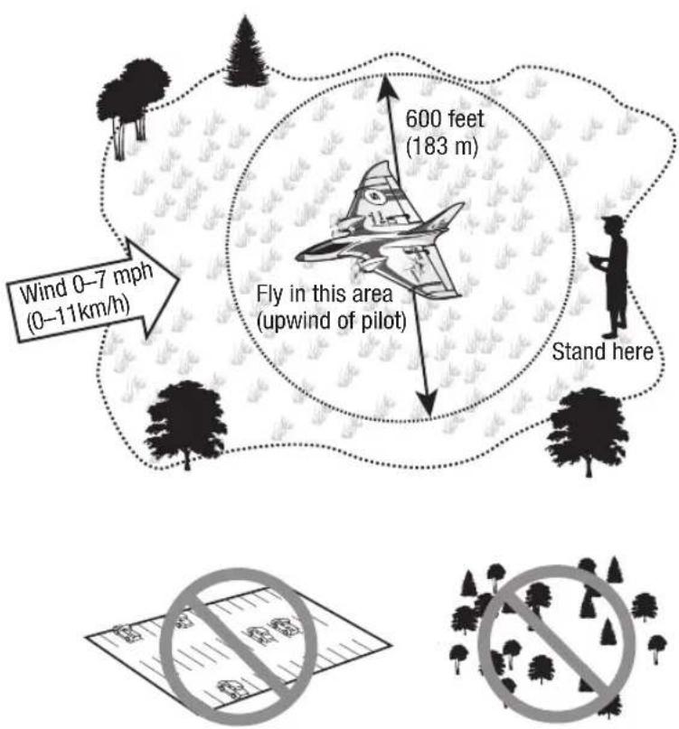
- Always operate your model in open spaces away from full-size vehicles, traffic and people.
- Always carefully follow the directions and warnings for this and any optional support equipment (chargers, rechargeable battery packs, etc.).
-
Always keep all chemicals, small parts and anything electrical out of the reach of children.
-
Always avoid water exposure to all equipment not specifically designed and protected for this purpose. Moisture causes damage to electronics.
- Never place any portion of the model in your mouth as it could cause serious injury or even death.
• Never operate your model with low transmitter batteries.
• Always keep aircraft in sight and under control.
• Always use fully charged batteries.
• Always keep transmitter powered on while aircraft is powered.
• Always remove batteries before disassembly.
• Always keep moving parts clean.
• Always keep parts dry.
• Always let parts cool after use before touching.
• Always remove batteries after use
• Always ensure failsafe is properly set before flying. - Never operate aircraft with damaged wiring.
- Never touch moving parts.
Charging Warnings

CAUTION: All instructions and warnings must be followed exactly. Mishandling of Li-Po batteries can result in a fire, al injury, and/or property damage.
- By handling, charging or using the included Li-Po battery, you assume all risks associated with lithium batteries.
- If at any time the battery begins to balloon or swell, discontinue use immediately. If charging or discharging, discontinue and disconnect. Continuing to use, charge or discharge a battery that is ballooning or swelling can result in fire.
- Always store the battery at room temperature in a dry area for best results.
-
Always transport or temporarily store the battery in a temperature range of 40–120°F (5–49°C). Do not store battery or aircraft in a car or direct sunlight. If stored in a hot car, the battery can be damaged or even catch fire.
• Always charge batteries away from flammable materials. -
Always inspect the battery before charging and never charge dead or damaged batteries.
- Always disconnect the battery after charging, and let the charger cool between charges.
- Always constantly monitor the temperature of the battery pack while charging.
- ONLY USE A CHARGER SPECIFICALLY DESIGNED TO CHARGE LI-PO BATTERIES. Failure to charge the battery with a compatible charger may cause fire resulting in personal injury and/or property damage.
• Never discharge Li-Po cells to below 3V under load. - Never cover warning labels with hook and loop strips.
• Never leave charging batteries unattended.
• Never charge batteries outside recommended levels.
• Never attempt to dismantle or alter the charger.
• Never allow minors under the age of 14 to charge battery packs. - Never charge batteries in extremely hot or cold places (recommended between 40–120°F or 5–49°C) or place in direct sunlight.
Included in the Box
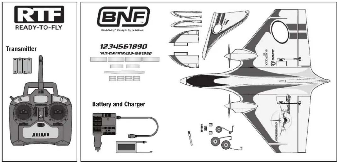
For more information and to register your product online, visit www.hobbyzonerc.com
text_image
600 feet (183 m) Fly in this area (upwind of pilot) Stand here Wind 0–7 mph (0–11km/h)Flying Tips
- Sensor Assisted Flight Envelope (SAFE™) technology is designed as flight assistance, not an autopilot. The pilot is always in control and required to fly the aircraft at all times.
- Start in Beginner mode (SAFE switch position 0). As you learn and become more confident, change modes to advance your flying skills.
- Always keep your aircraft in plain sight and upwind from you.
- Do not attempt your first turn at low altitude. Higher altitudes allow for greater possibility of correction.
• Always make deliberate and steady control stick movements for smooth control of your aircraft. - Do not fly in winds greater than 8-10 mph. If flying in winds 5-10mph and in beginner Mode (SAFE positon 0), you will likely need to fly in High Rates.
| Preflight Checklist | √ | |
| 1. | Find a safe and open area. | |
| 2. | Charge flight battery. | |
| 3. | Install flight battery in aircraft. | |
| 4. | Perform Control Direction Test. | |
| 5. | Plan flight for flying field conditions. | |
| 6. | Have fun! | |
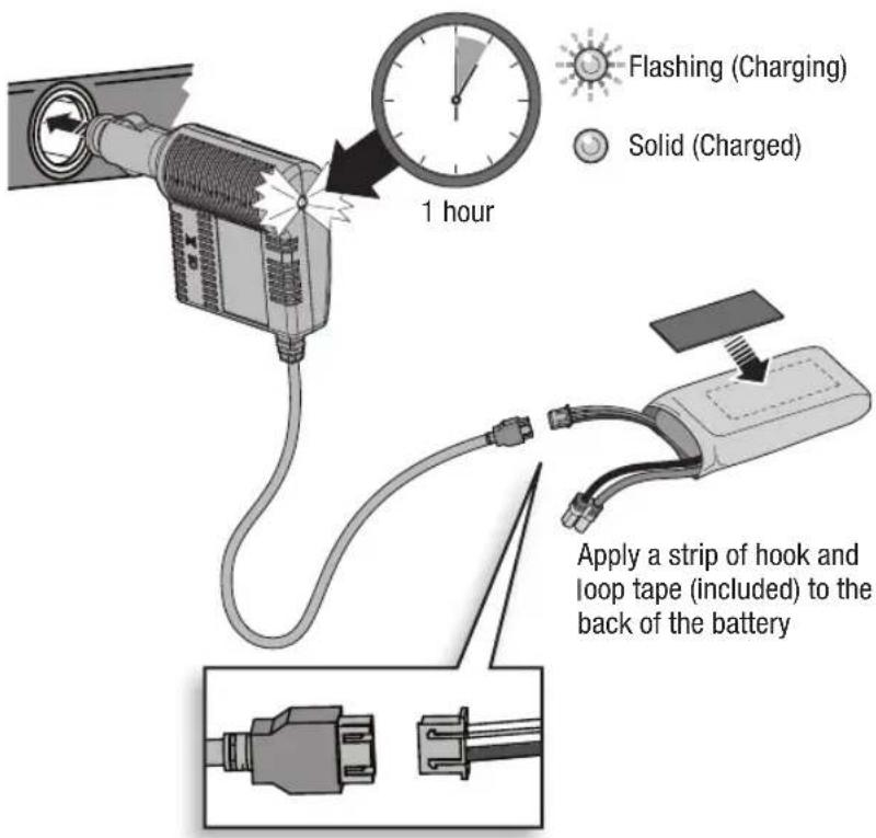
Charging the Flight Battery

CAUTION: When connecting the battery to the battery charger, make sure the connectors are aligned as shown. Failure to connect the battery properly could cause the terminals to short and result in fire, personal injury and/or property damage.
Charger Specifications
- Input power: 10–14V
• Max output voltage: 8.4V
• Fixed charge current: 1.5A
• Balances and charges 2S Li-Po cells with a minimum capacity of 1300mAh
This charger may be connected to a 1.5A AC Power Supply (sold separately). Refer to the Optional Parts List.
text_image
1 hour Flashing (Charging) Solid (Charged) Apply a strip of hook and loop tape (included) to the back of the battery
DX4e Transmitter
READY-TO-FLY
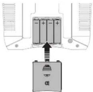
Remove the battery cover, install the four included batteries (noting proper polarity) and reinstall the battery cover.
text_image
Diagram showing battery charging process with positive and negative terminals and a battery symbol belowLow Battery Alarm
When the battery voltage drops below 4.7 volts, an alarm sounds and the voltage LEDs flash. The batteries must be replaced immediately. If this happens while flying, land your aircraft as soon and as safely as possible.

WARNING: Do not pick up the transmitter by the antenna. Do not alter or put weight on the antenna. Damage to antenna parts can decrease transmitter signal strength, which can result in loss of model control, injury or property damage.
text_image
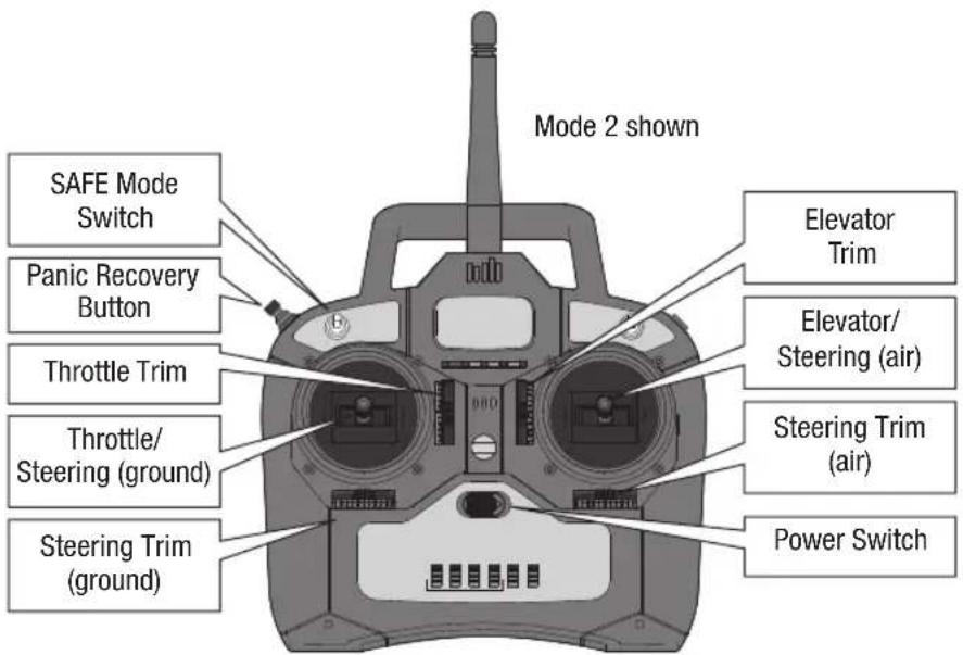
Mode 2 shown SAFE Mode Switch Panic Recovery Button Throttle Trim Throttle/ Steering (ground) Steering Trim (ground) Elevator Trim Elevator/ Steering (air) Steering Trim (air) Power SwitchCenter the Trims on your RTF DX4e before flight.
For more information on the transmitter, go to www.horizonhobby.com/products/SPMR4400 and click on the support tab for the Spektrum DX4e to download the instruction manual.

READY-TO-FLY
Your Delta Ray should already be bound to your included DX4E TX. IF you ever need to rebind, follow the step listed below in the Binding Procedure Reference Table.
- SAFE Flight mode is selected using Channel 5 signal (high, middle, low)
- Panic mode is selected with Channel 6 signal (high, low)
- Refer to your transmitter's manual for more information about transmitter setup
N = Normal R = Reverse

Bind-N-Fly." Ready to fly, redefined.
Setup for Optional Transmitter
To operate the SAFE ^TM system in this aircraft, set up your optional DSM2 ^® /DSMX ^® transmitter using the chart below.
A transmitter with a 2-position channel 5 switch will only allow the use of position 0 or position 2 flight modes. If possible, assign channel 5 in your transmitter to a 3-position switch to operate all 3 flight modes.
| Transmitter Thro Aile Elev Rudd | Gear/Ch 5 | Aux1 | Flight Mode/ Panic Switch | SAFE Flight Modes Supported | ||||
| DX4e (2pos) N | N N N N | N/A | Default 2 | pos Flight | Mode | |||
| DX4e (3pos) N | N N N N | N/A | Default 3 | pos Flight | Mode | |||
| DX5e (2pos) N | N N N N | N/A | Default 2 | pos Flight | Mode | |||
| DX5e (3pos) N | N N N N | N/A | Default 3 | pos Flight | Mode | |||
| DX6i | N | N | N | N | R | N | (Flap System) Norm UP Arrow 100 Land Down Arrow 100 | 2 pos Flight Mode |
| DX7 | N N N N | N | N | (Flap System) Norm Down Mid 0 Land UP 100(3 pos Aux1 switch-0 & 1 are normal, 2 is panic) | 2 pos Flight Mode | |||
| DX7s | N N N N | RR | (Switch Select) Gear to INH, FM to INH, Flap to Gear,Trainer to Aux1 | 3 pos Flight Mode | ||||
| DX8 | N N N N | (Switch Select) Gear to INH, FM to Gear, Flap to INH, Trainerto Aux 1 | 3 pos Flight Mode | |||||
| DX9 | N | N | N | N | N | RR | (Channel Input Config) Gear is B, Aux1 is switch i | 3 pos Flight Mode |
| DX10t | N | N | N | N | N | (Channel Input Config) Gear is A, Aux1 is R stick | 3 pos Flight Mode | |
| DX18 | N | N | N | N | N | (Channel Input Config) Gear is B, Aux1 is switch i | 3 pos Flight Mode | |
√ Binding Procedure Reference Table
| 1. Make sure the transmitter is powered off. | |
| 2. Make sure the transmitter controls are neutral, the throttle and throttle trim are in the low position, and the aircraft is immobile. | |
| 3. Install a bind plug in the receiver bind port. | |
| 4. Connect the flight battery in the aircraft. The receiver LED will begin to flash. | |
| 5. Power on the transmitter while holding the transmitter bind button. | |
| 6. When the receiver binds to the transmit-ter, the light on the receiver will turn solid and produce a series of three ascending tones. The tones will indicate the ESC is armed, provided the throttle stick and throttle trim are low enough to trigger arming. | |
| 7. Release the Bind button and remove the bind plug from the receiver. | |
| 8. Confirm that the aircraft is bound by moving controls. |
The receiver should retain the binding instructions received from the transmitter until another binding is done.

Bind-N-Fly.* Ready to fly, redefined.
Transmitter and Receiver Binding
Binding is the process of programming the receiver to recognize the GUID (Globally Unique Identifier) code of a single specific transmitter.
You need to 'bind' your chosen Spektrum™ DSM2/DSMX technology equipped aircraft transmitter to the receiver for proper operation.
Please visit www.bindnfly.com for a complete list of compatible transmitters.
Wingtip and Vertical Fin Installation
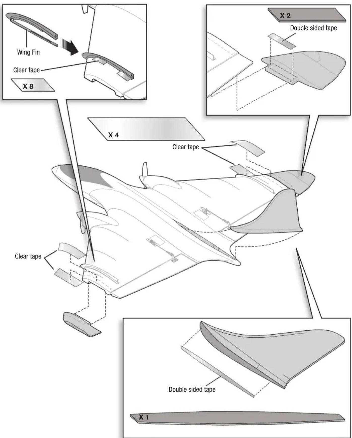
text_image
Wing Fin Clear tape X 8 X 2 Double sided tape X 4 Clear tape Clear tape Double sided tape X 1Installing the Flight Battery
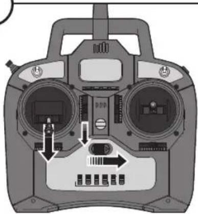
Lower the throttle and throttle trim, then power on the transmitter for at least 5 seconds.
1
natural_image
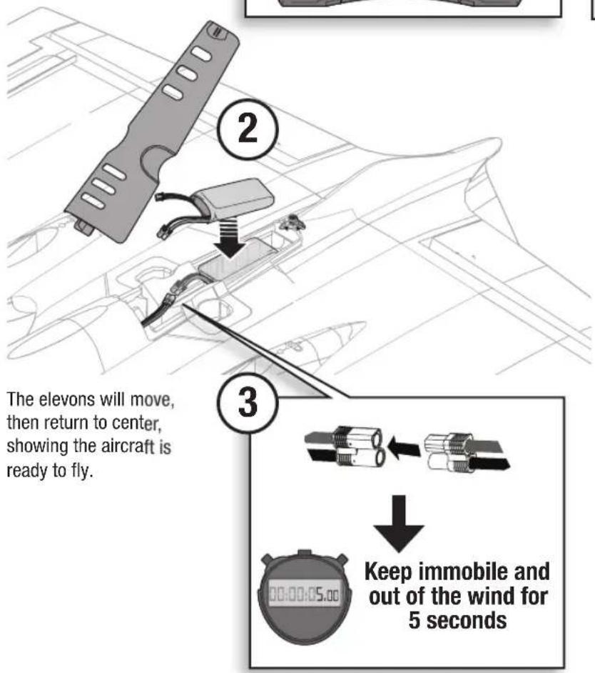
Interior view of a remote control device with dual motors and ports (no visible text or labels)CAUTION: Always disconnect the Li-Po flight battery from the aircraft receiver when not flying to avoid over-discharging the battery. Batteries discharged to a voltage lower than the lowest approved voltage may become damaged, resulting in loss of performance and potential fire when batteries are charged.

CAUTION: Always keep hands away from the propellers. SAFE technology will turn propellers in response to any aircraft movement.

text_image
The elevons will move, then return to center, showing the aircraft is ready to fly. ② ③ Keep immobile and out of the wind for 5 seconds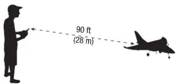
text_image
90 ft (28 m)Range Test
Before each flying session, and especially with a new model, you should perform a range check. Refer to your transmitter manual for more information.
Control Direction Test
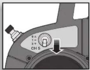
Perform the Control Direction Test with the transmitter's SAFE flight mode switch set to Experienced mode (position 2).

text_image
CH 5Experienced SAFE Flight Mode
Restrain the aircraft so it does not escape your control while you are testing your transmitter controls.
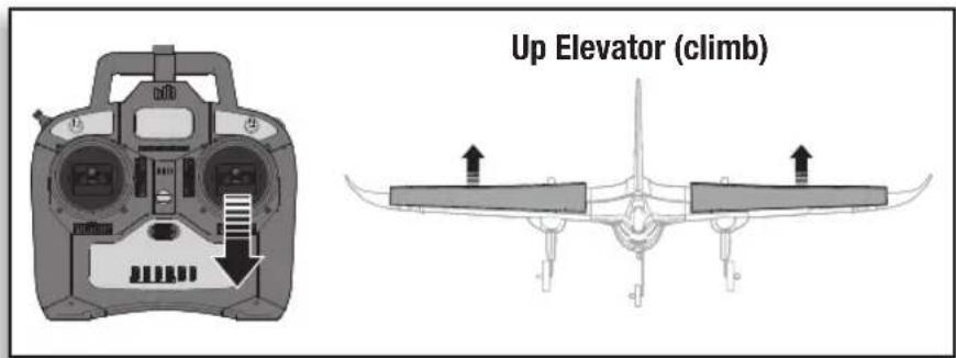
Move the sticks on the transmitter to ensure the aircraft responds as shown.
If your model does not respond as shown, DO NOT FLY! Refer to the Troubleshooting Guide in this manual for more information. If you need more assistance, contact the appropriate Horizon Hobby Product Support department.
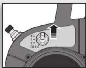
If the aircraft responds as shown, move the SAFE flight mode switch to Beginner mode (position 0) and center all trims to prepare to fly.

text_image
5 A 1 = 2 W CH 5Beginner SAFE Flight Mode
text_image
Up Elevator (climb)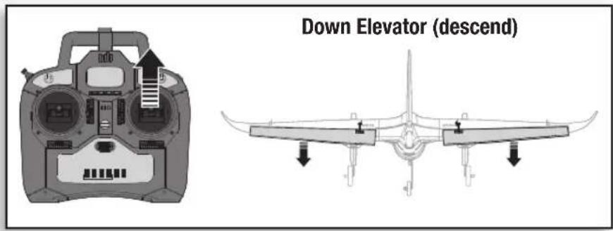
text_image
Down Elevator (descend)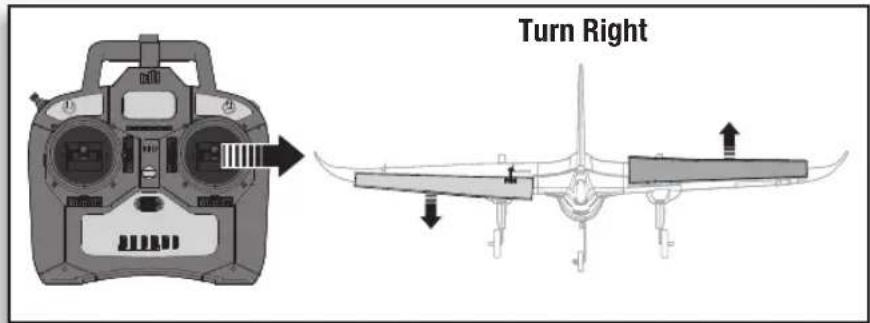
text_image
Turn Right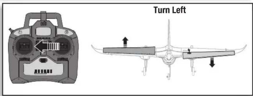
text_image
Turn Left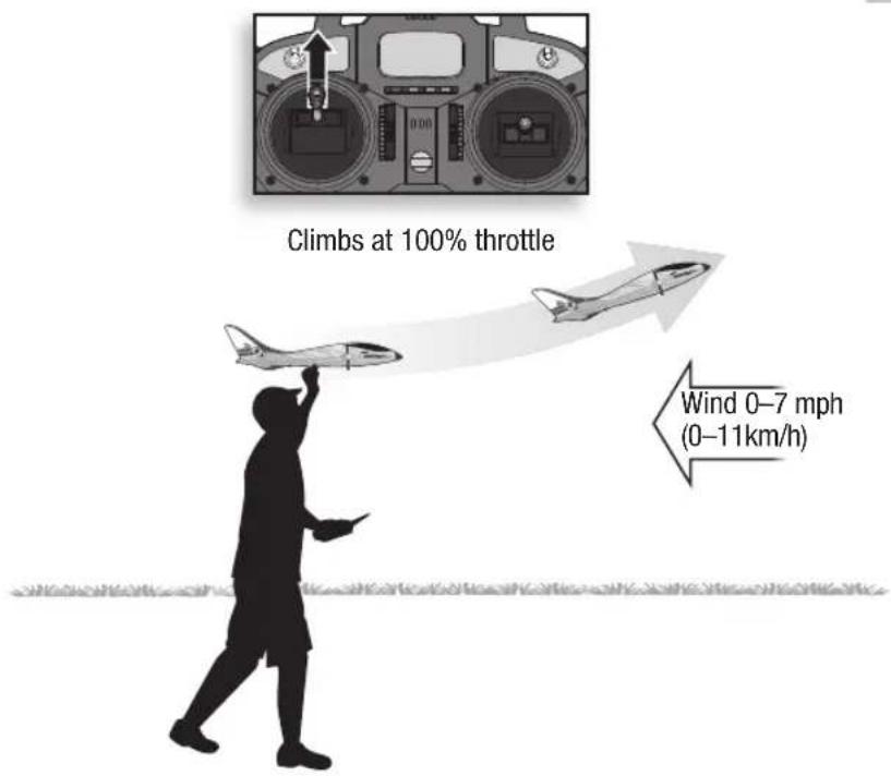
text_image
Climbs at 100% throttle Wind 0–7 mph (0–11km/h)Takeoff
Hand Launch
Hand launch in Beginner mode for first flights. Get help to hand launch your aircraft so you can concentrate on flying. If you must hand launch the aircraft alone, hold the model in your dominant hand and the transmitter in your other hand. An optional neck strap (SPMP610, sold separately) can help you hold the transmitter.
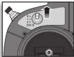
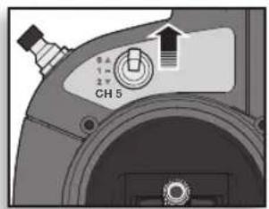
Beginner SAFE Mode (Switch Position 0)
text_image
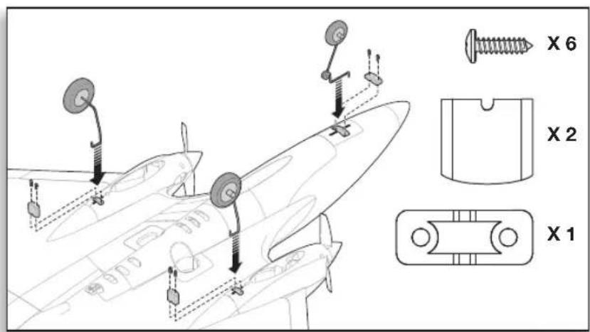
X 6 X 2 X 1Ground Launch
Install the landing gear as shown.
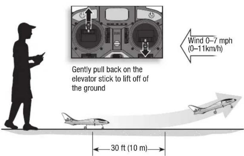
Use the Beginner mode for takeoff in first flights. If the ground is not hard and level, get help to hand launch your aircraft.
text_image
Gently pull back on the elevator stick to lift off of the ground Wind 0–7 mph (0–11km/h) 30 ft (10 m)Easy Launching
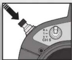
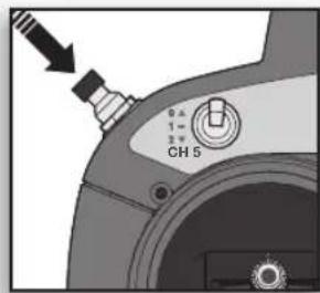
Launching is easier in Beginner mode if you hold the Panic Recovery button. Press and hold the button, then increase the throttle to 100%. Launch the aircraft. When the aircraft is up where you want to fly, release the button and decrease the throttle to 50–60%.
text_image
B 1- 3 CH 5
Flying
- In Beginner mode, when properly trimmed, your aircraft will climb at full throttle without use of the elevator stick.
- Make small and steady control stick movements for smooth control of your aircraft.
- Let the aircraft climb at full throttle, into the wind, until the aircraft gets about 150 feet (46 meters) above the ground, then decrease the throttle to half (50%).
- Flying with the nose pointed toward you is one of the hardest things to do when learning to fly. To practice piloting the aircraft, try flying in large circles high off the ground.
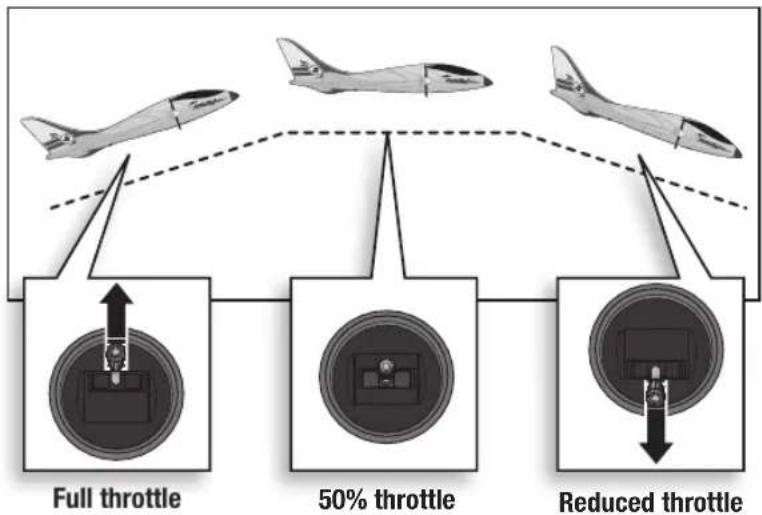
flowchart
graph TD
    A["Full throttle"] --> B["1"]
    C["50% throttle"] --> D["2"]
    E["Reduced throttle"] --> F["3"]
    B --> G["飞机"]
    D --> H["飞机"]
    F --> I["飞机"]
    style A fill:#f9f,stroke:#333
    style C fill:#f9f,stroke:#333
    style E fill:#f9f,stroke:#333
    style B fill:#ccf,stroke:#333
    style D fill:#ccf,stroke:#333
    style F fill:#ccf,stroke:#333

SAFE™ Technology Flight Modes
Beginner Mode:
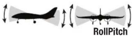
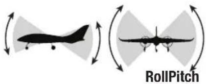
Pitch (nose up and down) and Roll (wing tips up and down) angles are limited to help you keep the aircraft airborne
Self-leveling
Intermediate Mode:
The pilot is only prevented from entering extreme flight conditions
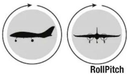
Experienced Mode
Unlimited Flight Envelope
Panic Recovery
text_image
0.5 1- 2.5 CH 5If you feel you have lost control in any mode, hold the Panic Recovery button. The SAFE technology will return the aircraft to a stable attitude (wings level with a slight climb). Always fly at a safe altitude, as Panic Recovery may cause the aircraft to lose some altitude when leveling the wings. Release the Panic Recovery button to turn off Panic mode and return to the current SAFE flight mode.
text_image
0.5 1 = 2 = CH 5Beginner Mode (Switch Position 0)
text_image
RollPitch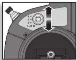
text_image
CH 5Intermediate Mode (Switch Position 1)
text_image
RollPitch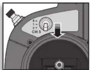
text_image
CH 5Experienced Mode (Switch Position 2)
text_image
RollPitch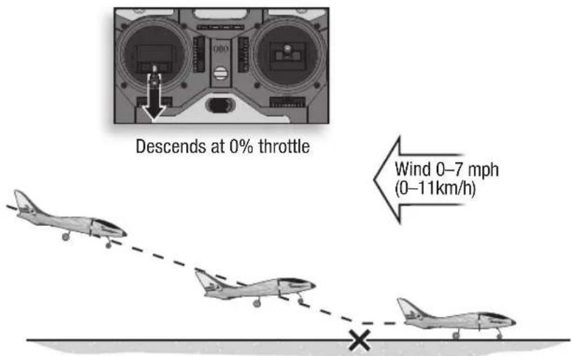
text_image
Descends at 0% throttle Wind 0–7 mph (0–11km/h)WARNING
natural_image
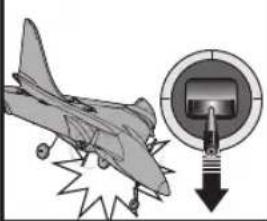
Illustration of an airplane with a magnified inset showing a control panel and a downward arrow (no text or symbols)Always decrease throttle at propeller strike.
| Post Flight Checklist | √ | |
| 1. | Disconnect flight battery from aircraft (Required for Safety). | |
| 2. | Remove flight battery from the aircraft. | |
| 3. | Power off transmitter. | |
| 4. | Recharge flight battery. | |
| 5. | Repair or replace all damaged parts. | |
| 6. | Store flight battery apart from the aircraft and monitor the battery charge. | |
| 7. | Make note of flight conditions and flight plan results, planning for future flights. | |
Landing
Land the aircraft in Beginner mode.
CAUTION: Never catch a flying aircraft in your hands. Doing so could cause personal injury and damage to the aircraft.

Easy Landing
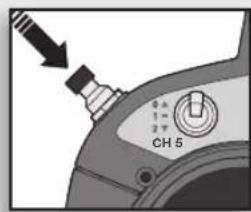
Landing is easier if you hold the Panic Recovery button. Line up for your landing, decrease the throttle to 0% and press and hold the Panic Recovery button. The aircraft will glide down wings level with the nose up (flared) for landing.

text_image
0 A 1 - 2 T CH 5NOTICE: If a crash is imminent, reduce the throttle. Failure to do so could result in extra damage to the airframe, as well as damage to the receiver and motors.
NOTICE: Crash damage is not covered under warranty.
Post Flight
NOTICE: When you are finished flying, never leave the aircraft in direct sunlight or in a hot, enclosed area such as a car. Doing so can damage the foam.
Adjusting Trim in Flight
Move the trim sliders for the controls as they are assigned on your transmitter. Familiarize yourself with your transmitter's controls and the aircraft's response before flying by performing the recommended Control Direction Test.
Elevator trim:
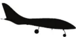
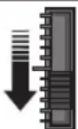
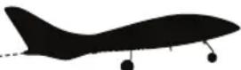
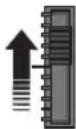
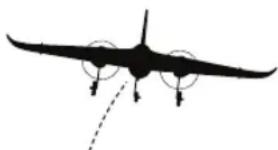
Trim the elevator at 50%-60% throttle. When the elevator is trimmed correctly, your aircraft will fly level at half throttle, climb steadily above half throttle and descend below half throttle.
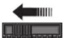
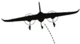
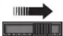
- If the aircraft's nose drifts up or down while the elevator stick is at neutral (centered) position, move the elevator trim slider by one or two "click" increments in the SAME direction as the drift.
Aileron trim:
When trimmed correctly, your aircraft flies with wings level.
- If the aircraft drifts left or right when the aileron stick is at neutral (centered) position, move the aileron trim slider by one or two "click" increments OPPOSITE the direction of roll.
If you must use more than 8 "clicks" on a trim slider to make the aircraft fly straight and level, land and adjust a control surface as described below.
Manually Adjusting Trim
Perform manual adjustment of trim before increasing the throttle above 25% or SAFE will move the control surfaces when the aircraft is moved.
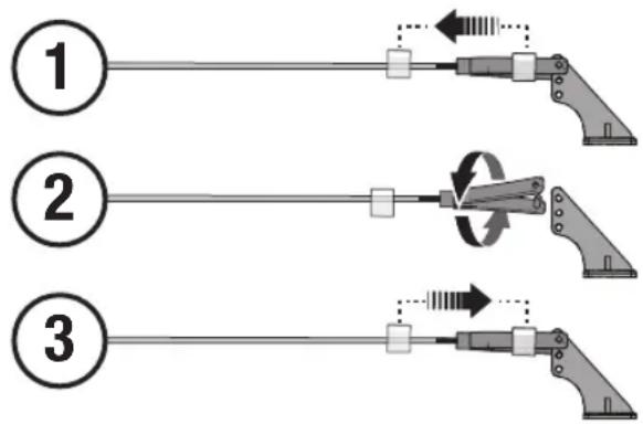
Return any trim setting on the transmitter to neutral by pushing the trim slider to the middle position, then adjusting the clevis on that control surface to position it the same as it was with the trim slider offset.
- Remove the clevis from the control horn.
- Turn the clevis (as shown) to lengthen or shorten the pushrod.
- Close the clevis onto the control horn and slide the tube towards the horn to secure the clevis.
ElevatorAileron
| Aircraft drift Required Trim | |
 |  Up Trim Up Trim |
 |  Down Trim Down Trim |
 |  Left Trim Left Trim |
 |  Right Trim Right Trim |
text_image
Diagram showing three sequential steps of a mechanical device with directional arrows indicating motion or movement.Troubleshooting Guide
| Problem Possible Cause Solution | ||
| Oscillation | Flying over recommended airspeed Reduce air speed | |
| Damaged propeller or spinner Replace propeller or spinner | ||
| Motor vibration | Replace parts or correctly align all parts and tighten fasteners as needed | |
| Loose receiver Align and secure receiver in fuselage | ||
| Loose aircraft controls | Tighten or otherwise secure parts (servo, arm, linkage, horn and control surface) | |
| Worn parts | Adjust gain to compensate for parts wear or replace worn parts (especially propeller, pivot points or servo) | |
| Trim is at extreme and aircraft does not fly straight or level | Trim is not at neutral | If you adjust trim more than 8 clicks, adjust the clevis to mechanically remove trim |
| Aircraft will not respond to throttle but responds to other controls | Throttle not at lowest position or throttle trim too high | Reset controls with throttle stick and throttle trim at lowest setting |
| Throttle channel is reversed Reverse throttle channel on transmitter | ||
| Motors disconnected from ESCs Make sure motors are connected to the ESCs | ||
| Extra propeller noise or extra vibration | Damaged propeller and spinner, collet or motor | Replace damaged parts |
| Propeller is out of balance Balance or replace propeller | ||
| Spinner is damaged or loose Repair or replace damaged spinner | ||
| Reduced flight time or aircraft underpowered | Flight battery charge is low Completely recharge flight battery | |
| Propeller installed backwards Install propeller with numbers facing forward | ||
| Propellers are installed incorrectly | Install propeller marked R on right and propeller marked L on the left | |
| Flight battery damaged Replace flight battery and follow flight battery instructions | ||
| Flight conditions may be too cold | Make sure battery is warm before use | |
| Aircraft will not Bind (during binding) to transmitter.Refer to the transmit-ter manual for binding instructions. | Transmitter too near aircraft during binding process | Move powered transmitter a few feet from aircraft, disconnect and reconnect flight battery to aircraft |
| Aircraft or transmitter is too close to large metal object, wireless source or another transmitter | Move aircraft and transmitter to another location and attempt binding again | |
| Flight battery/transmitter battery charge is too low | Replace/recharge batteries | |
| Bind switch or button not held long enough during bind process | Power off transmitter and repeat bind process. Hold transmitter bind button or switch until receiver is bound | |
| Aircraft will not connect (after binding) to transmitterRefer to the transmit-ter manual for binding instructions. | Transmitter too near aircraft during connecting process | Move powered transmitter a few feet from aircraft, disconnect and reconnect flight battery to aircraft |
| Aircraft or transmitter is too close to large metal object, wireless source or another transmitter | Move aircraft and transmitter to another location and attempt connecting again | |
| Flight battery/Transmitter battery charge is too low | Replace/recharge batteries | |
| Transmitter may have been bound to a different aircraft using different DSM protocol | Bind aircraft to transmitter | |
| Control surface does not move | Control surface, control horn, linkage or servo damage | Replace or repair damaged parts and adjust controls |
| Wire damaged or connections loose | Do a check of wires and connections, connect or replace as needed | |
| Flight battery charge is low Fully recharge flight battery | ||
| Receiver is damaged | Replace Receiver | |
| Controls reversed | Transmitter settings are reversed | Perform the Control Direction Test and adjust the controls on transmit-ter appropriately |
| Motor power pulses then motor loses power | Normal Low Voltage Cutoff (LVC) | Recharge flight battery or replace battery that is no longer performing |
| Weather conditions might be too cold | Postpone flight until weather is warmer | |
| Battery is old, worn out, or damaged | Replace battery | |
| Battery C rating might be too small | Use recommended battery | |
Service and Repair
Thanks to the Z-Foam ^™ material in the wing and fuselage of this aircraft, repairs to the foam can be made using virtually any adhesive (hot glue, regular CA [cyanoacrylate adhesive], epoxy, etc).
When parts are not repairable, see the Replacement Parts List for ordering by item number. For a listing of all replacement and optional parts, refer to the list at the back of this manual.

CAUTION: DO NOT handle a propeller, motor or ESC while the flight battery is connected to the ESC. Personal injury could result.
Disassembly
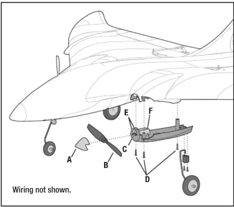
- Remove the spinner (A) by carefully pulling it away from the propeller (B).
- Hold the motor shaft (C) in place, then pull the propeller from the motor shaft.
- Remove 3 screws (D) from the motor cowling under the wing.
- Remove the cowling (that contains the motor) from the wing. Paint may keep the cowling attached to the wing.
- Remove 2 screws (E) from the front of the cowling that secures the motor.
- Disconnect the motor wires from the ESC wires.
- Remove the motor (F) and motor wires from the wing.
- Assemble in reverse order.
- Correctly center and attach the spinner to the propeller hub using CA (cyanoacrylate adhesive).
NOTICE: Make sure the propeller size numbers (4.75x2.5R for right side and 4.75X2.5L for left side) face out from the motor.
text_image
Wiring not shown.Prolong Battery Life
- Low Voltage Cutoff (LVC) pulses the power to the motors when the voltage gets low. When the motors pulse, land the aircraft immediately and recharge the flight battery.
- The aircraft can fly as recommended for approximately 8 minutes on one battery charge. Set a timer or stopwatch to let you know when it is time to land. However, if the motor begins to pulse (hits LVC), land immediately.
NOTICE: Repeated flying to LVC will damage the battery.

text_image
Diagram illustrating aircraft fuel efficiency with a battery, airline oscillation patterns, and a labeled airplane tailLimited Warranty
What this Warranty Covers
Horizon Hobby, Inc., (Horizon) warrants to the original purchaser that the product purchased (the "Product") will be free from defects in materials and workmanship at the date of purchase.
What is Not Covered
This warranty is not transferable and does not cover (i) cosmetic damage, (ii) damage due to acts of God, accident, misuse, abuse, negligence, commercial use, or due to improper use, installation, operation or maintenance, (iii) modification of or to any part of the Product, (iv) attempted service by anyone other than a Horizon Hobby authorized service center, (v) Product not purchased from an authorized Horizon dealer, or (vi) Product not compliant with applicable technical regulations.
OTHER THAN THE EXPRESS WARRANTY ABOVE, HORIZON MAKES NO OTHER WARRANTY OR REPRESENTATION, AND HEREBY DISCLAIMS ANY AND ALL IMPLIED WARRANTIES, INCLUDING, WITHOUT LIMITATION, THE IMPLIED WARRANTIES OF NON-INFRINGEMENT, MERCHANTABILITY AND FITNESS FOR A PARTICULAR PURPOSE. THE PURCHASER ACKNOWLEDGES THAT THEY ALONE HAVE DETERMINED THAT THE PRODUCT WILL SUITABLY MEET THE REQUIREMENTS OF THE PURCHASER'S INTENDED USE.
Purchaser's Remedy
Horizon's sole obligation and purchaser's sole and exclusive remedy shall be that Horizon will, at its option, either (i) service, or (ii) replace, any Product determined by Horizon to be defective. Horizon reserves the right to inspect any and all Product(s) involved in a warranty claim. Service or replacement decisions are at the sole discretion of Horizon. Proof of purchase is required for all warranty claims. SERVICE OR REPLACEMENT AS PROVIDED UNDER THIS WARRANTY IS THE PURCHASER'S SOLE AND EXCLUSIVE REMEDY.
Limitation of Liability
HORIZON SHALL NOT BE LIABLE FOR SPECIAL, INDIRECT, INCIDENTAL OR CONSEQUENTIAL DAMAGES, LOSS OF PROFITS OR PRODUCTION OR COMMERCIAL LOSS IN ANY WAY, REGARDLESS OF WHETHER SUCH CLAIM IS BASED IN CONTRACT, WARRANTY, TORT, NEGLIGENCE, STRICT LIABILITY OR ANY OTHER THEORY OF LIABILITY, EVEN IF HORIZON HAS BEEN ADVISED OF THE POSSIBILITY OF SUCH DAMAGES. Further, in no event shall the liability of Horizon exceed the individual price of the Product on which liability is asserted. As Horizon has no control over use, setup, final assembly, modification or misuse, no liability shall be assumed nor accepted for any resulting damage or injury. By the act of use, setup or assembly, the user accepts all resulting liability. If you as the purchaser or user are not prepared to accept the liability associated with the use of the Product, purchaser is advised to return the Product immediately in new and unused condition to the place of purchase.
Law
These terms are governed by Illinois law (without regard to conflict of law principals). This warranty gives you specific legal rights, and you may also have other rights which vary from state to state. Horizon reserves the right to change or modify this warranty at any time without notice.
WARRANTY SERVICES
Questions, Assistance, and Services
Your local hobby store and/or place of purchase cannot provide warranty support or service. Once assembly, setup or use of the Product has been started, you must contact your local distributor or Horizon directly. This will enable Horizon to better answer your questions and service you in the event that you may need any assistance. For questions or assistance, please visit our website at www.horizonhobby.com, submit a Product Support Inquiry, or call the toll free telephone number referenced in the Warranty and Service Contact Information section to speak with a Product Support representative.
Inspection or Services
If this Product needs to be inspected or serviced and is compliant in the country you live and use the Product in, please use the Horizon Online Service Request submission process found on our website or call Horizon to obtain a Return Merchandise Authorization (RMA) number. Pack the Product securely using a shipping carton. Please note that original boxes may be included, but are not designed to withstand the rigors of shipping without additional protection. Ship via a carrier that provides tracking and insurance for lost or damaged parcels, as Horizon is not responsible for merchandise until it arrives and is accepted at our facility. An Online Service Request is available at http://www.horizonhobby.com/content/_service-center_render-service-center. If you do not have internet access, please contact Horizon Product Support to obtain a RMA number along with instructions for submitting your product for service. When calling Horizon, you will be asked to provide your complete name, street address, email address and phone number where you can be reached during business hours. When sending product into Horizon, please include your RMA number, a list of the included items, and a brief summary of the problem. A copy of your original sales receipt must be included for warranty consideration. Be sure your name, address, and RMA number are clearly written on the outside of the shipping carton.
NOTICE: Do not ship LiPo batteries to Horizon. If you have any issue with a LiPo battery, please contact the appropriate Horizon Product Support office.
Warranty Requirements
For Warranty consideration, you must include your original sales receipt verifying the proof-of-purchase date. Provided warranty conditions have been met, your Product will be serviced or replaced free of charge. Service or replacement decisions are at the sole discretion of Horizon.
Non-Warranty Service
Should your service not be covered by warranty, service will be completed and payment will be required without notification or estimate of the expense unless the expense exceeds 50% of the retail purchase cost. By submitting the item for service you are agreeing to payment of the service without notification. Service estimates are available upon request. You must include this request with your item submitted for service. Non-warranty service estimates will be billed a minimum of 12 hour of labor. In addition you will be billed for return freight. Horizon accepts money orders and cashier's checks, as well as Visa, MasterCard, American Express, and Discover cards. By submitting any item to Horizon for service, you are agreeing to Horizon's Terms and Conditions found on our website http://www.horizonhobby.com/content/_service-center_render-service-center.
ATTENTION: Horizon service is limited to Product compliant in the country of use and ownership. If received, a non-compliant Product will not be serviced. Further, the sender will be responsible for arranging return shipment of the un-serviced Product, through a carrier of the sender's choice and at the sender's expense. Horizon will hold non-compliant Product for a period of 60 days from notification, after which it will be discarded.
Warranty and Service Contact Information
| Country of Purchase Horizon Hobby Contact Information Address | |||
| United States of America | Horizon Service Center(Repairs and Repair Requests) | servicecenter.horizonhobby.com/RequestForm/ | 4105 Fieldstone RdChampaign, Illinois, 61822 USA |
| Horizon Product Support(Product Technical Assistance) | www.quickbase.com/db/bghj7ey8c?a=GenNewRecordAir 888-959-2305 | ||
| Sales | sales@horizonhobby.comAir 888-959-2305 | ||
| United Kingdom | Service/Parts/Sales:Horizon Hobby Limited | sales@horizonhobby.co.uk+44 (0) 1279 641 097 | Units 1–4 , Ployters Rd, Staple TyeHarlow, Essex, CM18 7NS, United Kingdom |
| Germany | Horizon Technischer Service service@horizonhobby.deSales: Horizon Hobby GmbH +49 (0) 4121 2655 100 | Christian-Junge-Straße 125337 Elmshorn, Germany | |
| France | Service/Parts/Sales:Horizon Hobby SAS | infofrance@horizonhobby.com+33 (0) 1 60 18 34 90 | 11 Rue Georges Charpak77127 Lieusaint, France |
| China | Service/Parts/Sales:Horizon Hobby – China | info@horizonhobby.com.cn+86 (021) 5180 9868 | Room 506, No. 97 Changshou Rd.Shanghai, China 200060 |
FCC Information
Operation is subject to the following two conditions: (1) This device may not cause harmful interference, and (2) this device must accept any interference received, including interference that may cause undesired operation.

CAUTION: Changes or modifications not expressly approved by the party responsible for compliance could he user's authority to operate the equipment.
This product contains a radio transmitter with wireless technology which has been tested and found to be compliant with the applicable regulations governing a radio transmitter in the 2.400GHz to 2.4835GHz frequency range.
Antenna Separation Distance
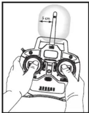
When operating your transmitter, please be sure to maintain a separation distance of at least 5 cm between your body (excluding fingers, hands, wrists, ankles and feet) and the antenna to meet RF exposure safety requirements as determined by FCC regulations.
This illustration shows the approximate 5 cm RF exposure area and typical hand placement when operating your transmitter.
IC Information
This device complies with Industry Canada licence-exempt RSS standard(s). Operation is subject to the following two conditions: (1) this device may not cause interference, and (2) this device must accept any interference, including interference that may cause undesired operation of the device.
natural_image
Illustration of hands operating a remote control device with a 5 cm distance indicator (no text or symbols on the device itself)Compliance Information for the European Union
| AT | BE | BG | CZ | CY | DE | DK | |
| EE | ES | FI | FR | GR | HR | HU | |
| IE | IT | LT | LU | LV | MT | NL | |
| PL | PT | RO | SE | SI | SK | UK | |
| IS | LI | NO | CH | ||||
Declaration of Conformity (in accordance with ISO/IEC 17050-1)
No. HH2013071101
Product(s): HBZ Delta Ray RTF
Item Number(s): HBZ7900
Equipment class: 2
The object of declaration described above is in conformity with the requirements of the specifications listed below, following the provisions of the European R&TTE directive 1999/5/EC, EMC Directive 2004/108/EC and LVD Directive 2006/95/EC:
EN 300-328 V1.7.1: 2006
EN 301 489-1 V1.9.2: 2012
EN 301 489-17 V2.1.1: 2009
EN60950-1:2006+A11:2009+A1:2010+A12:2011
EN55022:2010 + AC:2011
EN55024:2010

Signed for and on behalf of:
Horizon Hobby, Inc.
Champaign, IL USA
Jul 11, 2013
Robert Peak
Chief Financial Officer
Horizon Hobby, Inc
Declaration of Conformity (in accordance with ISO/IEC 17050-1)
No. HH2014010403
Product(s): HBZ Delta Ray BNF
Item Number(s): HBZ7980
Equipment class: 1
The object of declaration described above is in conformity with the requirements of the specifications listed below, following the provisions of the European R&TTE directive 1999/5/EC, EMC Directive 2004/108/EC and LVD Directive 2006/95/EC:
EN 301 489-1 V1.9.2: 2012
EN 301 489-17 V2.1.1: 2009
EN60950-1:2006+A11:2009+A1:2010+A12:2011
EN55022:2010 + AC:2011
EN55024:2010

Signed for and on behalf of: Horizon Hobby, Inc.
Champaign, IL USA
Jan 04, 2014
Robert Peak
Chief Financial Officer
Horizon Hobby, Inc
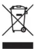
Instructions for disposal of WEEE by users in the European Union
This product must not be disposed of with other waste. Instead, it is the user's responsibility to dispose of their waste equipment by handing it over to a designated collections point for the recycling of waste electrical and electronic equipment. The separate collection and recycling of your waste equipment at the time of disposal will help to conserve natural resources and ensure that it is recycled in a manner that protects human health and the environment. For more information about where you can drop off your waste equipment for recycling, please contact your local city office, your household waste disposal service or where you purchased the product.
Replacement Parts • Ersatzteile • Pièces de rechange • Pezzi di ricambio
| Part # | Nummer Numéro | Codice | Description Beschreibung Description Descrizione | |||
| HBZ7925 | Fin /Wing TipSet: Delta Ray | HobbyZone Firebird Delta Ray: Finnenset | Delta Ray - Dérive/extrémités d'ailes | Set impenn/tip alari: Delta Ray |
| HBZ7926 | Motor Fairing Set: Delta Ray | HobbyZone Firebird Delta Ray: Motorverkleidung | Delta Ray - Set de carénages moteur | Set carenatura motore: Delta Ray |
| HBZ7985 | Bare Fuselage: Firebird Delta Ray | HobbyZone Firebird Delta Ray: Rumpf o. Einbauten | Delta Ray - Fuselage nu Solo fusoliera: Delta Ray | |
| HBZ7918 | Landing Gear Set: Delta Ray | HobbyZone Firebird Delta Ray: Fahrwerk und Kufenset | Delta Ray - Train d'atterrissage Set carrello: Delta Ray | |
| HBZ7909 | Pushrod/Horn Set: Delta Ray | HobbyZone Firebird Delta Ray: Gestänge | Delta Ray - Set de guignols et tringleries | Set comandi/squadrette: Delta Ray |
| HBZ7907 | Spinner&Prop Set: Delta Ray | HobbyZone Firebird Delta Ray: Gestänge | Delta Ray - Set d'hélice et de cônes | Set ogiva & elica: Delta Ray |
| HBZ7912 | Belly Hatch: Delta Ray | HobbyZone Firebird Delta Ray: Rumpfklappe unten | Delta Ray - Trappe à batterie Portello ventrale: Delta Ray | |
| HBZ7952 | Rubber Nose: Delta Ray | HobbyZone Firebird Delta Ray: Rumpfklappe unten | Delta Ray - Nez en caoutchouc Naso in gomma: Delta Ray | |
| HBZ7910 | Decal Set: Delta Ray | HobbyZone Firebird Delta Ray: Dekorbogen | Delta Ray - Planche de décoration | Set adesivi: Delta Ray |
| SPMR4400 | DX4e DSMX 4-Channel Full Range Tx only MD2/4 | DX4e DSMX 4-Kanal nur Sender MD2/4 | DX4e 4 voies DSMX Mode 2/4 | Solo Tx 4 canali DX4e DSMX MD2/4 |
| SPMR44001 | DX4e DSMX 4-Channel Full Range Tx only MD1/3 | DX4e DSMX 4-Kanal nur Sender MD1/3 | DX4e 4 voies DSMX Mode 1/3 | Solo Tx 4 canali DX4e DSMX MD1/3 |
| HBZ7728 | Brushed 180 Motor Set (2) | Hobbyzone Firebird Stratos Motor Set | Set de moteurs 180 à balais (2) | Set motore 180 con spazzole(2) |
| PKZ1080 | (2) SV80 Long Lead Servo | Parkzone SV80 Servo Servo SV80 | (2) (2) SV80 servo con cavo lungo | |
| EFLC3125 | 2-Cell DC Balancing Li-Po Charger | 2S DC Balancing Ladegerät Chargeur équilibreur LI-Po DC 2S | Caricabatterie per 2 celle Li-Po con bilanciatore | |
| EFLB13002S20 | 1300mAh 2S 7.4V 20C Li-Po, 13 AWG EC2 Battery | 1300mAh 2S 7.4V 20C Li-Po, 13 AWG EC2 Akku | Batterie LI-Po 7.4V 2S 1300mA 20C, prise EC2 | Batteria 1300mAh 2S 7.4V 20C Li-Po, 13 AWG EC2 |
| SPMA3160 | Delta Ray replacement receiver DSMX | HobbyZone Firebird Delta Ray: Ersatzempfänger DSMX | Delta Ray - Récepteur de remplacement DSMX | Delta Ray ricevitore di ricambio DSMX |
Optional Parts • Optionale Bauteile • Pièces optionnelles • Pezzi opzionali
| Part # | Nummer Numéro | Codice | Description Beschreibung Description Descrizione | |||
| HBZ7920 | Keychain Camera mount: Delta Ray | HobbyZone Firebird Delta Ray: Kamerahalter | Delta Ray - Support pour caméra porte clé | Supporto per telecamera tipo portachiavi Delta Ray |
| HBZ6513 | Alligator Clip: 12V Lighter Adapter | Krokodilklemme: 12 V Zigarettenanzünder | Adaptateur 12V allume cigare/ pinces croco | Pinze tipo coccodrillo: adattatore 12V per presa ac- cendisigari |
| HBZ1004 | 1.5A AC Power Supply (US Only) | 1.5A AC Power Supply (US Only) | Alimentation secteur 1.5A (USA uniquement) | 1.5A AC Alimentatore (solo USA) |
| EFLA111 | Li-Po Cell Voltage Checker | E-flite Li-Po Cell Volt Checker | Testeur de tension pour batterie Li-Po | Voltmetro per celle Li-Po |
| EFLA250 | Park Flyer Tool Assortment, 5 pc | E-flite Park Flyer Werkzeugsorti- ment, 5 teilig | Assortiment d'outils pour park- flyer, 5 pièces | Assortimento attrezzi per Park Flyer |
| EFLAEC202 | EC2 Battery Connector (2) | E-flite EC2 Akkubuchse (2) | Prise EC2 coté batterie (2) | EC2 Connettore batteria (2) |
| EFLAEC203 | EC2 Device & Battery Connector | E-flite EC2 Stecker / Buchse | Prise EC2 coté contrôleur et coté batterie | EC2 dispositivo & connettore batteria |
| EFLC3025 | Celectra 80W AC/DC Multi-Chemistry Battery Charger | Celectra 80 W AC/DC Multi-Chemistry-Batterieladegerät | Chargeur de batterie AC/DC Celectra 80 W multi-types | Caricabatterie per batteria multichimica 80 W c.a./c.c. |
© 2013 Horizon Hobby, Inc.
HobbyZone, the HobbyZone logo, Delta Ray, SAFE, the SAFE logo, Z-Foam, DSM, DSM2, DSMX, EC2, Celectra and the Horizon Hobby logo are trademarks or registered trademarks of Horizon Hobby, Inc.
The outline and trim scheme of the Firebird Delta Ray were designed by Quique Somenzini in cooperation with Mirco Pecorari of Aircraft Studio Design.
The Spektrum trademark is used with permission of Bachmann Industries, Inc.
Patents Pending
www.hobbyzonerc.com
HBZ7900 / HBZ7980