AD5HPMREU - Computer Accessories Addonics - Free user manual and instructions
Find the device manual for free AD5HPMREU Addonics in PDF.


User questions about AD5HPMREU Addonics
0 question about this device. Answer the ones you know or ask your own.
Ask a new question about this device
Download the instructions for your Computer Accessories in PDF format for free! Find your manual AD5HPMREU - Addonics and take your electronic device back in hand. On this page are published all the documents necessary for the use of your device. AD5HPMREU by Addonics.
USER MANUAL AD5HPMREU Addonics
natural_image
Illustration of an electronic device chassis with ports, connectors, and a central display (no text or symbols)User Guide
5-Port HPM-XU
(AD5HPMREU)
www.addonics.com
v8.1.11
Technical Support
If you need any assistance to get your unit functioning properly, please have your product information ready and contact Addonics Technical Support at:
Hours: 8:30 am - 6:00 pm PST
Phone: 408-453-6212
Email: http://www.addonics.com/support/query/
text_image
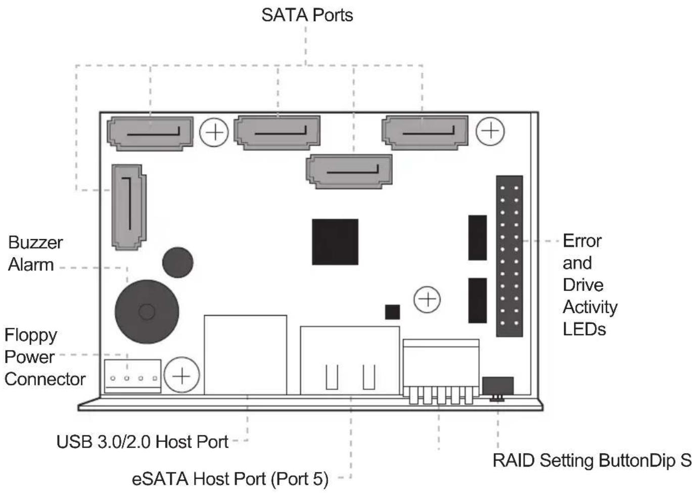
SATA Ports Buzzer Alarm Floppy Power Connector USB 3.0/2.0 Host Port eSATA Host Port (Port 5) Error and Drive Activity LEDs RAID Setting ButtonDip S| Dip Switch Settings | |||||
| Raid Mode | 2 3 | 4 | 5 | ||
| Individual Drive (Factory Default) | OFF | OFF | OFF | OFF | OFF |
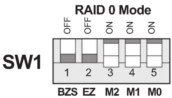
| 0 | OFF | OFF | ON | ON | ON |
| 1 and 10 | OFF | OFF | ON | ON | OFF |
| 3 | OFF | OFF | ON | OFF | OFF |
| 5 | OFF | OFF | OFF | ON | OFF |
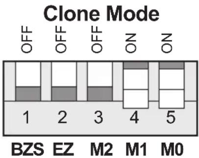
| Clone | OFF | OFF | OFF | ON | ON |
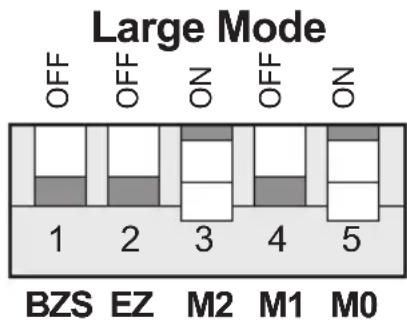
| Large | OFF | OFF | ON | OFF | ON |
| Enable ERR Buzzer Function | Auto-Rebuilding to Spare Drive | Port Multiplier Mode | |||
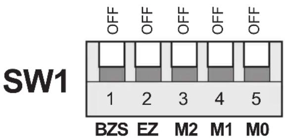
Default factory DIP Switch setting:
SW1 – RAID Setting DIP Switch
BZS – Error buzzer function
EZ – Automatic rebuilding to spare drive (one of the drives on the raid is set as a spare). If EZ is ENABLED anda drive failure occurs, the spare will automatically act as a drive replacement and rebuilding will automatically start.
M2 - RAID mode 2
M1 - RAID mode 1
M0 - RAID mode 0
text_image
SW1 1 2 3 4 5 BZS EZ M2 M1 M0- Error buzzer function is ENABLED (BZS) when dip switch is in OFF position
- Auto-rebuilding to spare drive is DISABLED (EZ)
- Individual drive mode is ENABLED (M0\~M2)
Note: When the default factory RAID setting is used, independent drive configuration and optical drive are supported only when connecting to controllers with Silicon Image Sil3124, Sil3132 chip set or controllers that are Port Multiplier (PM) compatible. Simultaneous DVD writing was tested using the Nero Burning Rom.
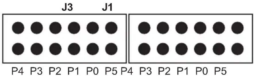
LED Pin Header
Error LED Activity LED
J1 – Drive Activity LED
P5 – Activity LED for eSATA host port lights up when it is connected to a SATA controller card.
P0, P1, P2, P3 & P4 - Activity LEDs for port 0, 1, 2, 3, 4 & 5 light up when a drive is connected and blinks when there's drive activity.
J3 – Error LED
P5 – error LED for eSATA host port
P0, P1, P2, P3 & P4 - error LED for port 0, 1, 2, 3, 4 & 5
Cable Connections
- Attach the SATA hard drives (up to 5) to the SATA ports on the Hardware Port Multiplier (HPM) using SATA cables. It is recommended to connect drives to the SATA ports 1 to 5 successively.
- To provide power to the HPM, connect a 4-pin floppy power cable from the system power supply to the floppy power connector on the HPM.
- Optional: Connect LEDs to the Activity & Error LED jumper block
Setting or Modifying the RAID Mode Using the JMicron HW RAID Manager Utility Program:
- For Windows users, install the JMicron HW RAID Manager located on the SATA Controller CD. In the CD, go to Configuration Utilities > JMB393. This manager can be used to create and monitor the status of the RAID volume.
It is recommended to use the default factory RAID DIP switch setting when using the JMicron HW RAID Manager.
- Modify the RAID mode on the 5-port HPM-XU using DIP switch
Recommended to be used on operating system without JMicron HW RAID Manager support like Linux, Mac & Solaris. Windows users can also use the procedure below.
Note: Steps A to D need to be performed each time the raid mode is modified.
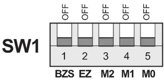
a. Set the DIP switch as shown below.
text_image
SW1 OFF OFF OFF OFF OFF 1 2 3 4 5 BZS EZ M2 M1 M0b. Press the RAID setting button with a ball point pen.
c. While pressing the RAID setting button turn on the system power where the HPM is connected. The buzzer will sound while holding the RAID setting button. Release it after at least 5 seconds for hardware initialization. A single beep will be heard to indicate initialization is completed. The above steps act as a reset.
d. Power off the system power.
e. On the DIP switch, change (M0 to M2) setting to the desired RAID mode using the diagram below.
All settings on the diagram shows
- Error buzzer function is ENABLED
- EZ function is DISABLED.
bar_stacked
RAID 0 Mode | Mode | BZS | EZ | M2 | M1 | M0 | | :--- | :--- | :--- | :--- | :--- | :--- | | SW1 | 1 | 2 | 3 | 4 | 5 |SW1
bar
Clone Mode | Category | BZS | EZ | M2 | M1 | M0 | |---|---|---|---|---|---| | 1 | OFF | OFF | OFF | ZO | ZO | | 2 | OFF | OFF | OFF | ZO | ZO | | 3 | OFF | OFF | OFF | ZO | ZO | | 4 | OFF | OFF | ZO | ZO | ZO | | 5 | OFF | OFF | ZO | ZO | ZO |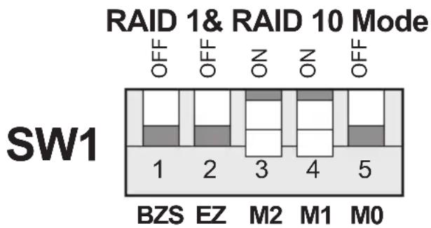
bar_stacked
RAID 1& RAID 10 Mode | Category | BZS | EZ | M2 | M1 | M0 | |---|---|---|---|---|---| | SW1 | OFF | OFF | NO | NO | OFF | | | | | | | | | | | | | | | | | | | | | | | | | | | | | | | | | | | | | | | | | | | | | | | | | | | | | | | | | | | | | 3 | 4 | 5 | SW1SW1
bar_stacked
Large Mode | Category | OFF | OFF | NO | OFF | NO | |---|---|---|---|---|---| | 1 | 1 | 1 | 1 | 1 | 0 | | 2 | 1 | 1 | 1 | 1 | 0 | | 3 | 1 | 1 | 1 | 1 | 0 | | 4 | 1 | 1 | 1 | 1 | 0 | | 5 | 1 | 1 | 1 | 1 | 0 |
bar_stacked
RAID 3 Mode | Category | BZS | EZ | M2 | M1 | M0 | | :--- | :--- | :--- | :--- | :--- | :--- | | SW1 | 1 | 2 | 3 | 4 | 5 |SW1
text_image
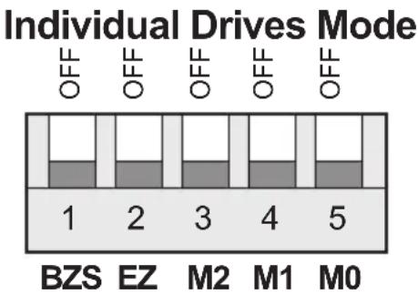
Individual Drives Mode OFF OFF OFF OFF OFF 1 2 3 4 5 BZS EZ M2 M1 M0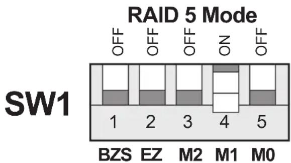
bar_stacked
RAID 5 Mode | Category | BZS | EZ | M2 | M1 | M0 | | :--- | :--- | :--- | :--- | :--- | :--- | | SW1 | OFF | OFF | OFF | ON | OFF | | | | | | | | | | | | | | | | | | | | | | | | | | | | | | | | | | | | | | | | | | | | | | | | | | | | | | | | | | | | | 3 | 4 | 5 | SW1RAID Setting Notes:
bar_stacked
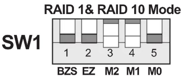
RAID 1& RAID 10 Mode | Category | BZS | EZ | M2 | M1 | M0 | | :--- | :--- | :--- | :--- | :--- | :--- | | SW1 | 1 | 2 | 3 | 4 | 5 |When 2 drives are connected to the HPM-XU, and DIP switch is set to this setting, the 2 drives will be configured as a 2-drive RAID1 array.
When 4 drives are connected to the HPM-XU, the 4 drives will be configured as a 4-drive RAID10 array.
bar_stacked
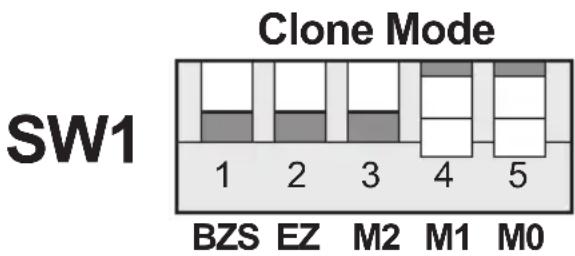
| Category | Value | | -------- | ----- | | BZS | 1 | | EZ | 2 | | M2 | 3 | | M1 | 4 | | M0 | 5 |Clone's action is similar to RAID1. However, all of the hard drives will be mirrored. Clone mode is useful especially when users like to copy data from a source hard drive to the drives connected to the HPM-XU.
f. Press the RAID setting button with a ball point pen.
g. While pressing the RAID setting button turn on the system power where the HPM is connected. The buzzer will sound while holding the RAID setting button. Release it after at least 5 seconds for hardware initialization. A single beep will be heard to indicate initialization is completed.
h. Verify if the RAID array is detected by the system.
i. If the 5-port HPM-XU is connected to the motherboard onboard SATA, on the CMOS setup utility, the raid array will display as "Addonics H/W RAID5" if setup as a RAID5 array.
j. If the 5-port HPM-XU is connected to an eSATA host controller card, on the RAID BIOS, the raid array will display as "Addonics H/W RAID0" if setup as a RAID0 array.
k. If booted into Windows, in Disk Drives under Device Manager, the raid array will display as "Addonics H/W LARGE" if setup as a LARGE array.
I. Once raid array is verified, you can set the buzzer either ON or OFF.
Notes on Spare Drives using the Easy RAID Setting (EZ)
When EZ function is ENABLED, the auto-rebuilding to spare drive is automatic.
The degraded RAID group will start rebuilding automatically by using the existing spare drive.
* Spare drive can be either plugged before RAID building or a new drive can be plug as the spare drive when RAID rebuild is required.
A. Which port acts as a spare drive?
The last drive will automatically become the spare drive.
For a 3-drive RAID5 with spare:
Drives connected to SATA ports 1\~3 belong to the active RAID5 array and drive connected to port 4 is the spare.
For a 4-drive RAID10 with spare:
Drives connected to SATA ports 1\~4 belong to the active RAID10 array and drive connected to port 5 is the spare.
For a 2-drive RAID1 with spare:
Drives connected to SATA ports 1&4 belong to the active RAID1 array and drive connected to port 5 is the spare.
B. When will rebuild action start?
- When the raid fails and EZ is enabled, the HPM-XU will automatically rebuild the RAID group using the spare.
- When the raid fails and EZ is disabled, the HPM-XU will NOT rebuild the raid group unless you install a good drive to replace the failed drive.
CONTACT US
www.addonics.com
Phone: 408-573-8580
Fax: 408-573-8588
Email: http://www.addonics.com/sales/query/