
LNR0208C - Video recorder LINKSYS - Free user manual and instructions
Find the device manual for free LNR0208C LINKSYS in PDF.

| Product Type | Network Video Recorder (NVR) |
| Model | LNR0208C |
| Brand | Linksys |
| Processor | Marvell |
| Memory | 1 GB |
| Max HDD Capacity | 8 TB (2 x 4 TB) |
| HDD Bays | 2 x hot-swappable with lock |
| LAN Port | 1 x Gigabit RJ-45 |
| USB Ports | 3 x USB 2.0 (1 front, 2 rear) |
| eSATA Ports | 2 |
| DI/DO | 4 inputs, 2 outputs |
| Power Supply | External 60 W, 100-240 V |
| Power Consumption | 15.9 - 20.8 W (typical) |
| Dimensions (WxDxH) | 114.97 x 246.1 x 164.94 mm (4.53 x 9.69 x 6.49 in) |
| Weight | 2.09 kg |
| Operating Temperature | 0°C to 40°C |
| Operating Humidity | 0% to 95% |
| Video Compression | H.264, MJPEG, MPEG-4 |
| Max Throughput | 150 Mbps |
| Supported Channels | Up to 8 |
| RAID Levels | JBOD/Linear, RAID0, RAID1, RAID5 |
| Remote Access | Live View and Playback |
| ONVIF Support | Yes |
| Security | Kensington lock slot |
| Fan | 1 quiet cooling fan |
| Maintenance | Clean with a dry cloth; avoid liquids. |
Frequently Asked Questions - LNR0208C LINKSYS
User questions about LNR0208C LINKSYS
0 question about this device. Answer the ones you know or ask your own.
Ask a new question about this device
Download the instructions for your Video recorder in PDF format for free! Find your manual LNR0208C - LINKSYS and take your electronic device back in hand. On this page are published all the documents necessary for the use of your device. LNR0208C by LINKSYS.
USER MANUAL LNR0208C LINKSYS
LED Indicators Status .2
How to Access Web Configuration .....2
Quick Configuration....3
Start Quick Configuration . . . . . . . . . . . . . . . . . . . . . . . . . . . . . . . . . . . . . . . . . . . . 3
Live View 6
Playback 12
Configuration 21
Camera Settings....21
Video Settings 23
Camera Status 23
Recording Settings 23
Event & Action Management .....25
E-Mail Settings 28
Disk Management....29
File System Management 30
File Sharing Service 30
Network Setup 31
Network Management 32
DDNS....32
User Management....32
Log System 33
Reboot & Shutdown. 38
Specification....39
Introduction
Before You Use This Product
Verify that all the accessories listed on the Package Contents section of the Quick Installation Guide are included. Before installing your NVR, please read the instructions in the Quick Installation Guide to avoid misuse. Follow the instructions in the Hard Disk Installation section of the Quick Installation Guide to avoid damages due to faulty installation.
NotE
LiveView and Playback features are Not compatible with Mac OS X.
Hardware Description
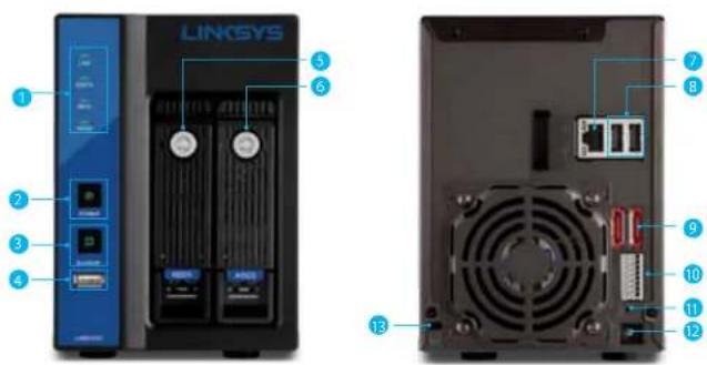
- LED indicators: LAN, eSATA, HDD1, HDD2
- Power button
- USB BACKUP button - Auto video backup
- USB 2.0 port (For USB storage drive)
- HDD1
- HDD2
- Gigabit LAN
- USB 2.0 x 2 (Reserved for future use)
- eSATA x 2
- DI/DO (4 in 2 out)
Top to bottom: Vcc5V, GND, DI-1, DI-2, DI-3, DI-4, DO-1, DO-2
- Reset button
- Power connector
- Kensington security slot
LED Indicators Status
natural_image
Front view of a LINKSYS server rack unit with two front-mounted drive bays and two rear-mounted ports (no visible text or labels)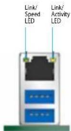
LEDs on Front Panel
| LED Color & Status Indicate | ||
| LAN Off LAN Link is not established | ||
| eSATA Off No data transmission | ||
| HDD Off Hard disk drive is not detected | ||
| Power | Off Power off | |
| Green solid Power on | ||
| USB Backup | Off | USB device is not detected |
| Blue solid | USB device is ready | |
| Blue blinking | NVR data is being copied to the USB device | |
| Red solid Backup error | ||
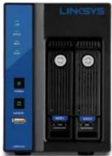
LEDs on RJ-45 Port on Rear Panel
| LED | Position | Status | Indicate |
| LAN | Link/Activity (Right LED) | Off | LAN Link is not established |
| Yellow solid | LAN Link is established | ||
| Yellow blinking | LAN is being accessed | ||
| LAN | Speed (Left LED) | Off | 10M/100Mbps connection or no connection |
| Orange solid | 1000Mbps connection |
NOTE
- USB BACKUP will beep and begin after pressing BACKUP button for three seconds.
- To turn off your NVR, press the power button for at least three seconds.
- To turn on your NVR, press the power button for at least three seconds.
How to Access Web Configuration
- To access the NVR's Web Configuration, open a web browser and enter the IP address of the NVR.
NOTE
- If you don't have a DHCP server in the network, the default NVR IP address is 192.168.1.253.
Linksys
Introduction
- Enter username and password. The default username and password are "admin" and "admin."
- Allow ActiveX Control or plugin to be installed on your computer if prompted.
NOTE
LiveView and Playback features are NOT compatible with Mac OS X.
Quick Configuration
The first time you log in, the system will direct you through Quick Configuration, or you can click the Wizard icon to launch the Quick Installation.
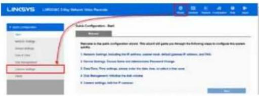
Start Quick Configuration
- The wizard will describe the five steps for configuration. Click Start.
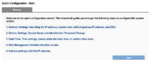
2) Configure the NVR's network settings to allow your NVR to work properly within your network. After you enter all the information, click Next.
- Obtain an IP address automatically - If this option is selected, your NVR will be assigned a dynamic IP address by a DHCP server (such as a router) once the NVR connects to the network.
- Specify an IP address - If there is no DHCP server, the default IP address is 192.168.1.253. That address should work in most network environments. You can change the IP address on this page. You SHOULD change the IP address if you have more than one NVR in the same LAN.
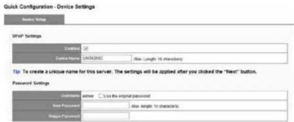
3) Configure your UPnP settings and device password. Click Next.
UPnP Settings - Universal Plug and Play (UPnP) simplifies the process of adding a NVR to a local area network. Once connected to a LAN, the NVR will automatically appear on the Windows network. Enable UPnP and give the device a name.
Password Settings - You should change the password from the default "admin." Enter a new password in the New Password field and enter it again in Retype Password field.
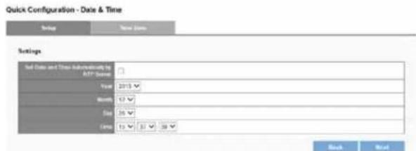
4) Configure your device's date and time. You can have the NVR automatically set date and time with NTP server or you can configure it manually. If you want the NVR to automatically set date the time, select the Time Zone tab and choose the time zone of your area. Click Next.
Linksys
Introduction
NOTE
Verifying and adjusting current local time and daylight saving time will help you avoid the following errors:
• Incorrect display time for playback videos.
• Inconsistent display time of event logs and when they actually occur.
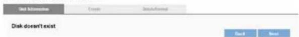
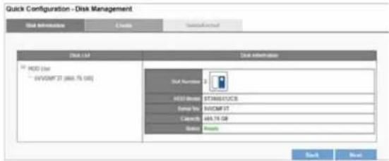
5) If no hard disk drives are installed in your NVR, the page will show "Disk doesn't exist." Once a hard disk drive is installed, the Disk Information tab will show the details about that device and allow you to create a new RAID disk. After you enter all information, click.
Quick Configuration - Disk Management
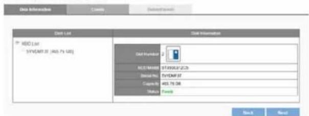
6) Disk Information provides details of the hard disk drive: Slot Number, HDD Model, Serial No., Capacity and Status. After your disk is created, click Next.
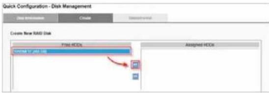
Quick Configuration - Disk Management
a) Click Create to enter the Create New RAID Disk window. Select the hard disk drive in the Free HDDs field.
Quick Configuration - Disk Management
![Create Information Create Create New RAID Disk Free HCCs HDDMF3F (HDD-GS) Assigned HCCs Available RAID Disk Big Drive(Linear) [0 GB] Fault Tarrant(Radd1) [0 GB] Performance(Radd2) [0 GB] Fault Tarrant(Radd3) [0 GB]](/content/2026/05/773384/images/9a94ca4634ae8a4f4dda40ee69d440e34a63fb3a98a082473b9f8f5e7fc4b965.jpg)
b) The selected hard disk drive will be marked in blue. Click to move the hard disk drive into the Assigned HDDs field.
![Quick Configuration - Disk Management File Information File Settings Create New RAIL End File XDCs Assigned HEDs [ ] (1.0) [ ] (2.0) [ ] (3.0) [ ] (4.0) [ ] (5.0) [ ] (6.0) [ ] (7.0) [ ] (8.0) [ ] (9.0) [ ] (10.0) [ ] (11.0) [ ] (12.0) [ ] (13.0) [ ] (14.0) [ ] (15.0) [ ] (16.0) [ ] (17.0) [ ] (18.0) [ ] (19.0) [ ] (20.0) [ ] (21.0) [ ] (22.0) [ ] (23.0) [ ] (24.0) [ ] (25.0) [ ] (26.0) [ ] (27.0) [ ] (28.0) [ ] (29.0) [ ] (30.0) [ ] (31.0) [ ] (32.0) [ ] (33.0) [ ] (34.0) [ ] (35.0) [ ] (36.0) [ ] (37.0) [ ] (38.0) [ ] (39.0) [ ] (40.0) [ ] (41.0) [ ] (42.0) [ ] (43.0) [ ] (44.0) [ ] (45.0) [ ] (46.0) [ ] (47.0) [ ] (48.0) [ ] (49.0) [ ] (50.0) [ ] (51.0) [ ] (52.0) [ ] (53.0) [ ] (54.0) [ ] (55.0) [ ] (56.0) [ ] (57.0) [ ] (58.0) [ ] (59.0) [ ] (60.0) [ ] (61.0) [ ] (62.0) [ ] (63.0) [ ] (64.0) [ ] (65.0) [ ] (66.0) [ ] (67.0) [ ] (68.0) [ ] (69.0) [ ] (70.0) [ ] (71.0) [ ] (72.0) [ ] (73.0) [ ] (74.0) [ ] (75.0) [ ] (76.0) [ ] (77.0) [ ] (78.0) [ ] (79.0) [ ] (80.0) [ ] (81.0) [ ] (82.0) [ ] (83.0) [ ] (84.0) [ ] (85.0) [ ] (86.0) [ ] (87.0) [ ] (88.0) [ ] (89.0) [ ] (90.0) [ ] (91.0) [ ] (92.0) [ ] (93.0) [ ] (94.0) [ ] (95.0) [ ] (96.0) [ ] (97.0) [ ] (98.0) [ ] (99.0) [ ] (100.0)](/content/2026/05/773384/images/1647b98a3dafc89cf108c3d18f04c6aedbc3cdb9260db6fd7542153fafc77251.jpg)
Linksys
Introduction
c) The selected hard disk drive in Assigned HDDs field will be marked in blue.
![Quick Configuration - Disk Management Data importation Create Delete Create New RAID Disk Fine HDOs Assigned HDDs [HTTP 10.145 GB] Available RAID Disk Big Drive(Linear) [ABS-GB] ○ Performance(Radd) [ABS-GB] Fault Tolerant(Radd) [0 GB] ○ Fault Tolerant(Radd) [0 GB] Apply Cancel](/content/2026/05/773384/images/e91ee11194b1a79c0f379ef5ac9ebfdc1a592eeddfcbcae9e5470e2422b0ed1a.jpg)
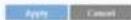
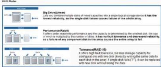
d) You can choose from four types of disk configuration. Choose a disk configuration and click Apply.
![Quick Configuration - Disk Management Create New RAID Disk Free HCDs Assigned HDDs [145 GB] [145 GB] [145 GB] Acoustable RAID Disk ● Rig Drive(Lower) [465 GB] ○ Performance(Rack1) [465 GB] ○ Fault Tolerant(Rack1) [0 GB] ○ Fault Tolerant(Rack2) [0 GB] Apply Cancel](/content/2026/05/773384/images/cd042c4eab33e74ac3da9d9203bfeaf63afd9fe9ea305b9aebe0493a09e7943e.jpg)
| Big Drive (Linear) | Big Drive is a collection of hard disk drives and does not provide any RAID protection. The data are written to the disks continuously. |
| Performance (RAID0) | RAID0 combines two or more hard disk drives to function as one larger volume. Data are written to the hard disk drives without any parity information. Total storage capacity is the sum of all hard disk drives. |
| Fault Tolerant (RAID1) | A RAID1 array requires two hard disk drives. RAID1 provides disk mirroring by duplicating the data between two hard disk drives. |
| Fault Tolerant (RAID5) | A RAID5 array requires a three or more hard disk drives. Data are striped in all hard drives in a RAID5 array, and parity information is stored in each drive. If a hard disk drive fails, the array enters degraded mode. The data can be rebuilt from other member drives after installing a new drive to replace the failed one. |
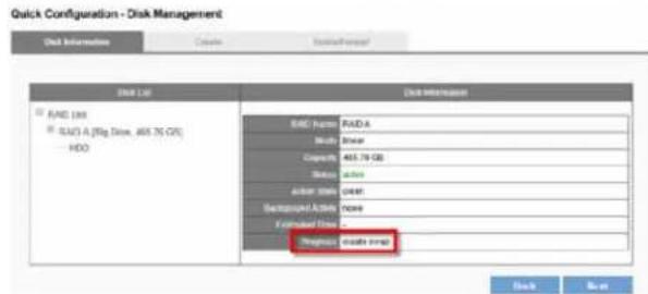
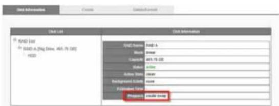
e) Configuration progress is tracked in the Disk Information window. When formatting progress reaches 100%, configuration mode switches to "create swap."
NOTE
Don't turn off the server or unplug any hard drives when RAID Disk configuration is in process.
Linksys
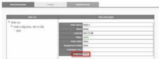
Introduction
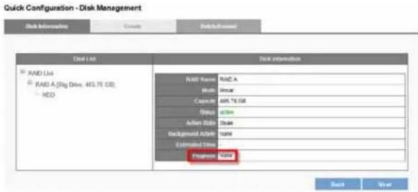
f) When progress reads, "none," the RAID disk configuration is complete. After the RAID disk is created, RAID Disk List shows details about the disk: RAID Name, RAID type, Capacity, Status, Action State, Background Activity, Estimated Time and Progress.
7) You can add camera in Camera Settings. After your camera is added, click Next.
8) The window will show the completed status. You can click Back to return to the previous steps to modify the configuration or click Start Live View to complete quick configuration and start monitoring.
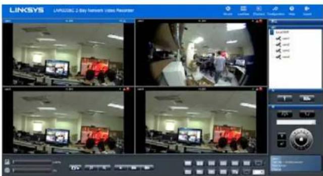
LiveView
When Quick Configuration is complete, NVR will guide you to live view. You can view a live video stream from your network camera via LAN, and monitor the stream remotely.
NOTE
LiveView and Playback features are NOT compatible with Mac OS X.
| Mode Description | |
 | WizardStart Quick Configuration. |
 | LiveViewControl the monitoring instantaneously. |
 | PlaybackPlay and export recorded video files. |
 | ConfigurationConfigure network camera, recording & event,disk management, network, managementand system. |
 | HelpGet technical support from Linksys. |
 | logoutLeave NVR. |
Main Functions
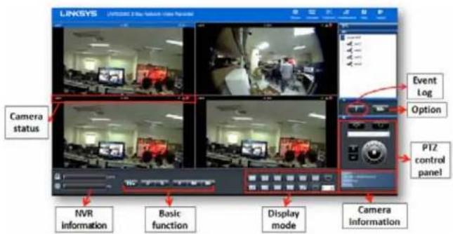
Disk and CPU loading indicator - View disk and CPU loading directly without entering the Configuration page. Disk and CPU indicator is blue when loading is 70% or less, and red when it gets higher than 70%. RAID type and video configuration settings, including resolution, FPS and video quality, can influence CPU loading.

Icon Description
 | SnapshotTo save still photos. The image will display in a pop-up window. Clipboard - Copy the image to device's temporary memory. You can paste the image into a graphics program such as Paint for advanced editing.Save - Save image to default path.Cancel - Cancel snapshot. Clipboard - Copy the image to device's temporary memory. You can paste the image into a graphics program such as Paint for advanced editing.Save - Save image to default path.Cancel - Cancel snapshot. |
 | Digital zoom out/ InSelect a channel to enable digital zoom function |
 | DropDrop the camera from LiveView |
 | Drop allDrop all cameras from LiveView |
 | Add allAdd all cameras to LiveView |
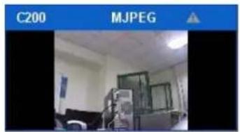
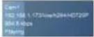 | Camera informationCamera name, IP address, bit rate, and status |
Display mode
Click the icon of display mode to select how many screens you want to monitor. When you click a display mode its icon will turn blue.
| Icon Description | |
 | Full Screen |
 | 1 screen |
 | 4 screen |
 | 9 screen |
 | 10 screen |
 | 12 screen |
 | 16 screen |
 | 20 screen |
 | 25 /30/ 36/49 screen |
 | 5+1 screen |
 | 7+1 screen |
 | 12+1 screen |
 | Sequential modeClicktochoose the page of Liveview.In Options, set the sequential interval (in seconds) for display mode. |
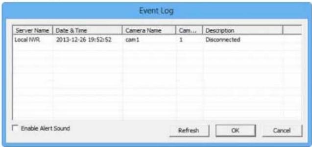
Event Log Icon

Event Log notifies users immediately upon motion detection. When motion is detected, the icon will start blinking. Once the icon is blinking, click the button and a pop-up window will display the list of events and the icon will stop blinking.
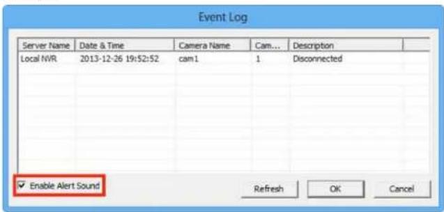
You can enable the remote Web browser to sound an alarm when motion is detected.
Option Icon

- General
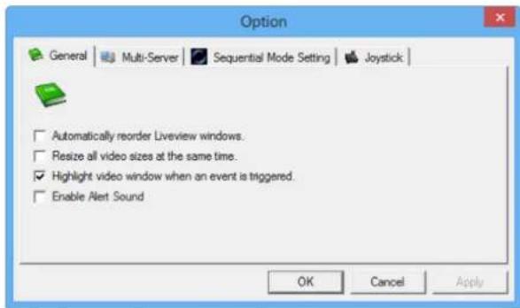
Automatically reorder LiveView windows - Rearrange video in order without blank grid when dropping video from LiveView.
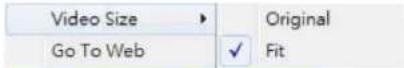
Resize all videos at the same time - Right-click on the video to set all live videos screen to either original size or fit size.
natural_image
Interior view of a room with ceiling lights and a camera unit, no visible text or symbolsHighlight video window when event is triggered - A warning frame will pop out on the channel when an event is triggered.
Enable Alert Sound - The remote web browser will sound an alarm when motion is detected.
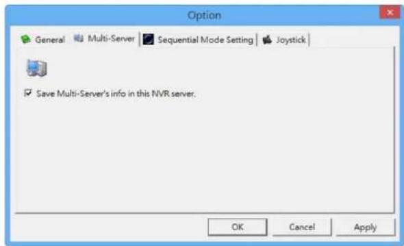
- Multi-Server
To save the Multi-Server information inLiveView page.
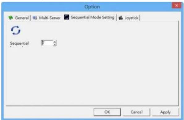
- Sequential Mode Setting
Set the interval (in seconds) for sequential mode.
Linksys
Introduction
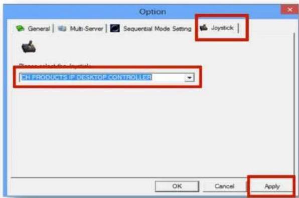
- Joystick
Manipulate PTZ camera with a USB joystick. Once you apply the Joystick function, the PTZ icon in status bar indicates joystick enabled.
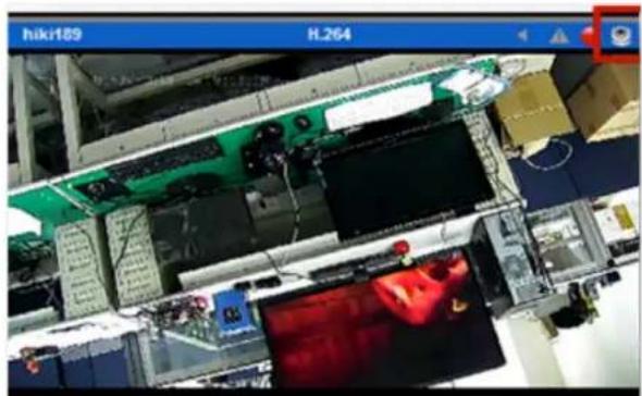
natural_image
Interior view of a factory assembly line with electronic components and a monitor (no visible text or symbols)PTZ Control Panel
If your network camera supports PTZ function, use the control panel to adjust the viewing angle. The following functions are available depending on the camera models.
| Icon Description | |
 | PTZ panelPTZ allows you to monitor large areas with a single network camera. Pan, tilt, and zoom functions can be controlled remotely. If device supports PTZ control, click on the arrows to pan and/or tilt the camera. Clicking the house icon returns the camera to its original monitoring position. |
| Preset positionsSelect from your camera's preset positions. | |
 | Optical zoom in/outAdjust the PTZ camera to zoom out or zoom in. |
 | Schedule for PTZSet camera preset position.It opens the dialog box to set how many times to repeat PTZ cruise, and how many seconds between each preset point.Repeat(1~999 times, 1000 infinite):1000Interval(3~1200 seconds):$OK Cancel |
 | Schedule for PTZClick Go to start PTZ patrol schedule. |
Linksys
Introduction
Exchange Streaming
If your IP cameras support dual stream, the NVR allows you to configure dual streaming in the Cameras Parameters page. Performance will be best if you set stream 1 at a higher resolution than stream 2. To switch streams, select the channel in theLiveView page and right-click to show the list.
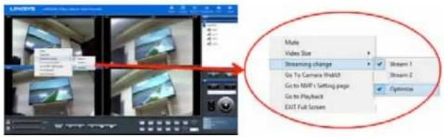
When optimize is enabled: the streaming type will be adjusted automatically for different display modes.
When optimize is disabled - you can manually adjust streaming type, which will be memorized in different display modes.
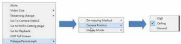
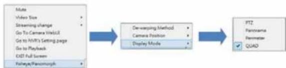
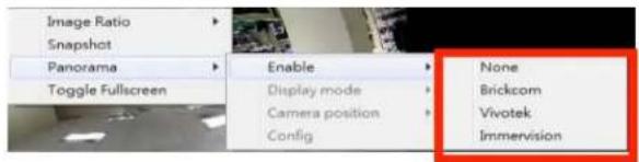
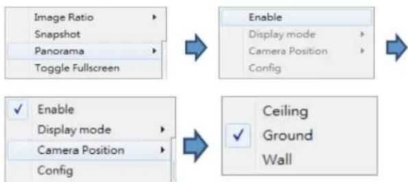
De-warp for fisheye cameras
Right-click on the video and choose a de-warp engine for cameras with fisheye.
1) Choose camera position.
flowchart
graph LR
    A["Make Video Size"] --> B["Steaming Change"]
    B --> C["Go To Camera Web/UE"]
    C --> D["Go to NVR's Setting page"]
    D --> E["Go to Playback"]
    E --> F["Exit Full Screen"]
    F --> G["Fishaya/Paramorph"]

    B --> H["De-warping Method"]
    H --> I["Camera Position"]
    I --> J["Display Mode"]

    J --> K["Wall"]
    K --> L["Celting"]
    K --> M["Ground"]
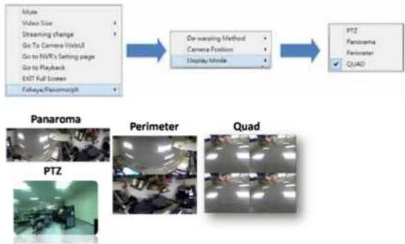
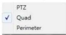
2) Choose display mode.
flowchart
graph TD
    A["Video Size"] --> B["Streaming change"]
    B --> C["Go To Camera Web/Off"]
    C --> D["Go to NV's Setting page"]
    D --> E["Go to Playback"]
    E --> F["EXIT Full Screen"]
    F --> G["Fisheye/Fancomorph"]

    H["De-warping Method"] --> I["Camera Position"]
    I --> J["Display Mode"]

    K["PTZ"] --> L["Panorama"]
    L --> M["Perimeter"]
    M --> N["Quad"]

    O["Panorama"] --> P["PTZ"]
    P --> Q["Perimeter"]
    Q --> R["Quad"]
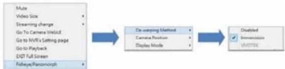
De-warp for Immervision Lenses
Right-click on the video and choose the de-warp engine for cameras with Immervision lenses.
1) Choose De-warping Method.
flowchart
graph LR
    A["Make Video Size"] --> B["De scanning Method"]
    C["Streaming change"] --> B
    D["Go To Camera Web/UI"] --> B
    E["Go to MVR's Setting page"] --> B
    F["Go to Playback"] --> B
    G["EXIT Full Screen"] --> B
    H["Fisheye/Ransomorph"] --> B
    B --> I["Disabled"]
    I --> J["Immunization"]
    I --> K["Unidentified"]
2) Choose Display Mode.
flowchart
graph LR
    A["Make Video Size Streaming change Go To Camera WorkUp Go to MVC's Getting page Go to Playback EXT Full Screen Foehage/Pancorch"] --> B["De-rewping Method Camera Position Display Mode"]
    B --> C["PTZ Panorama Penemater QUAD"]
Linksys
Introduction
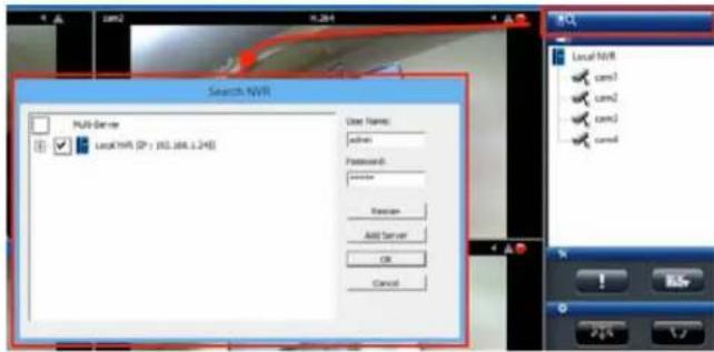
Multi-NVR server
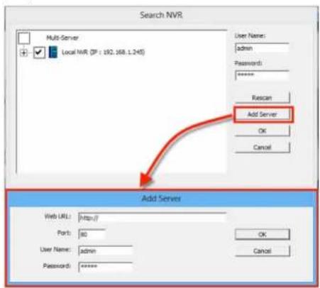
Add a multi-NVR server by clicking the search box. Enter the User Name and password for the NVR you wish to add to the local server. The NVR will appear. Click cameras up to 144 channels to add them into camera list. Click OK to add cameras or rescan to search for NVR again.
Add Server - NVRs can be manually added by entering URL or IP address, port, User Name and Password.
Playback
Playback allows you to view recorded videos from cameras connected to your NVR. The NVR offers synchronized playback for up to four cameras, and easy steps to help you sort through the recorded videos quickly. You can view Playback video in full screen, and take and save snapshots during playback.
NOTE
LiveView and Playback features are NOT compatible with Mac OS X.
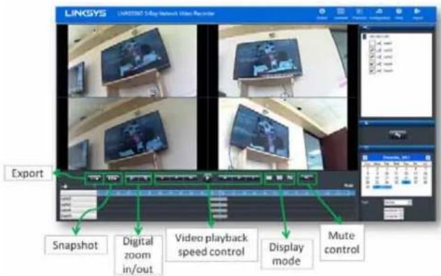
Main Functions
Mute

Choose whether to play audio with videos.
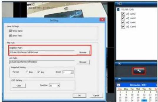
Setting

To configure playback settings, click the button and choose the parameters for files to play and how they will be displayed on screen (OSD).
Linksys
Introduction
Display mode

One Screen

Full Screen

Four Screens
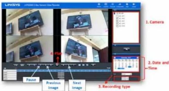
Video playback controls
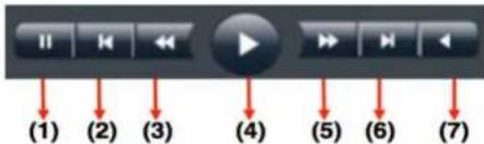
(1) Pause - temporarily stop the playback.
(2) Previous Image - show the previous image or video.
(3) Slow motion - play in slower speeds.
(4) Play - play video file.
(5) Forward - speed up playback.
(6) Next image - show the next image or video.
(7) Rewind - play backward.
Play Speed Indicator
The play speed is displayed beside timetable.
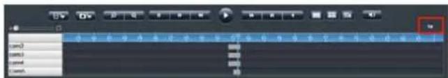
Scale bar
Use the scale slider to increase or reduce the time period for which you wish to check video files from timetable.
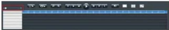
Seek bar
The seek bar allows you to go to a specific point in a recording.
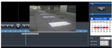
Thumbnail in Playback - The thumbnail function displays a snapshot of a specific moment when you move the seek bar within a recording. The thumbnail also provides related information, such as date, time and camera name.
Digital zoom
Snapshot

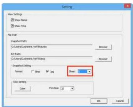
You can save an image from playback by clicking the Snapshot icon. Before taking a snapshot, choose a save location. Click the Settings icon and choose a snapshot path. You can capture up to five consecutive frames as snapshots.
De-warp for fisheye cameras
Right-click on the video and you can choose the proper de-warp engine for cameras with fisheye or Immervision Lens.
- Choose the de-warp engine:
- Choose the mounting type
flowchart
graph TD
    A["Image Ratio"] --> B["Snapshot"]
    B --> C["Panorama"]
    C --> D["Toggle Fullscreen"]
    E["Enable"] --> F["Display mode"]
    F --> G["Camera Position"]
    G --> H["Config"]
    I["Enable"] --> J["Display mode"]
    J --> K["Camera Position"]
    K --> L["Config"]
    M["Ceiling Ground Wall"] --> N["✓"]
- Choose the display mode
Change OSD (on-screen display) color and font size
1) Click Setting icon.

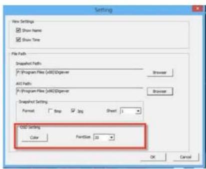
2) Click Color, select the OSD color and click OK.
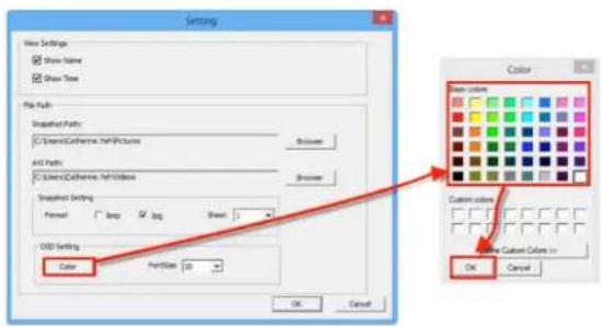
3) Select font size from drop-down list and click OK.
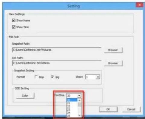
4) The font size and color are changed on the playback screen.
Linksys
Introduction
Video Playback
Before viewing recorded videos, click the Setting icon to set recorded videos for playback.
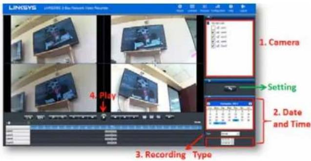
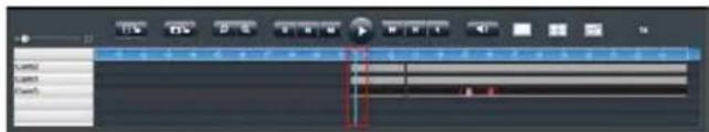
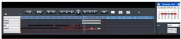
1) Select cameras from camera list and select up to four camera numbers to search recorded videos.
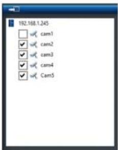
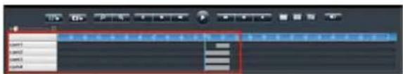
Once the camera is selected, a timeline will be shown on the timetable.
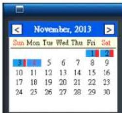
2) Please select the date the video was recorded. The date marked in blue has recorded video.
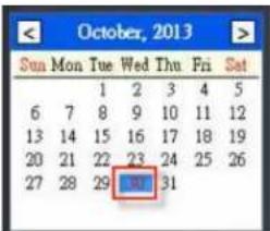
If there is an event recording in the specific date, the date will be marked as blue with a red stripe beside it.
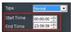
You can also select a specific time period (start time to end time). Time is expressed as hour:minute:second. The default time period is from 00:00:00 to 23:59:59.
Linksys
Introduction
3) Select recording type. There are five types of video files: Normal (Gray), Event (Red), Video Clip (Black), Recovery (Blue) and Daylight saving time (Green). Default recording type is Normal.
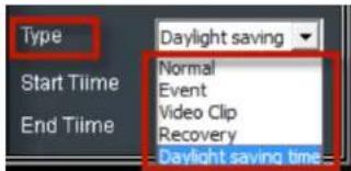
Timetable will display the colors in a remote browser.
3) Click Play button

Frame by Frame Playback
1) Follow "Steps to Playback Videos" section above.
2) Click Pause button.
3) Click Previous Image or Next Image button.
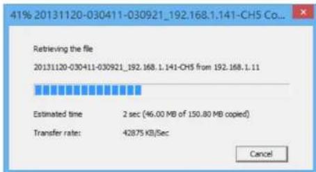
Export Files
The export function allows you to retrieve recorded video files from a server.
1) Before exporting files, choose a save location. Click a path to save the video file.

to choose
2) Select an AVI path where exported files and click OK.
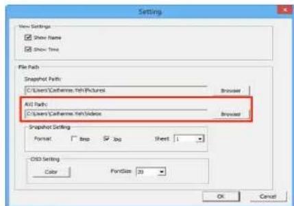
3) Choose cameras and time ranges to export.
4) Press to export the video file. Both NVRPlayer and NVRCheck will be exported with the video files.
- NVRPlayer is the player of NVR recording file.
- NVRCheck is a tool to verify the files were recorded on the NVR.
Play Video Files Remotely
Accessing video files via Networking Sharing and FTP Service. You must enable Networking Sharing and FTP Service in File Sharing Management under Disk Management on the NVR Configuration page.
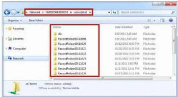
Find my record video files with network sharing
1) Go to the Network folder and find the NVR device name.
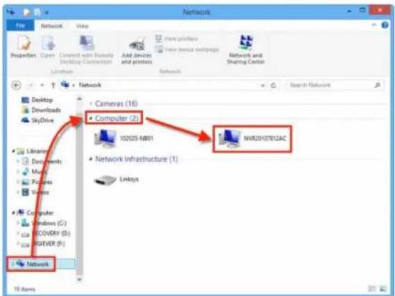
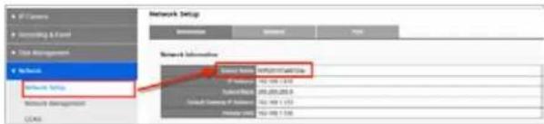
2) The Device Name can be found in Network > Network Setup > Information on the Configuration page.
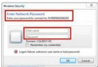
3) Double-click on the device to log in with a User name and Password. If you haven't changed them, the User name and Password are "admin" and "admin."
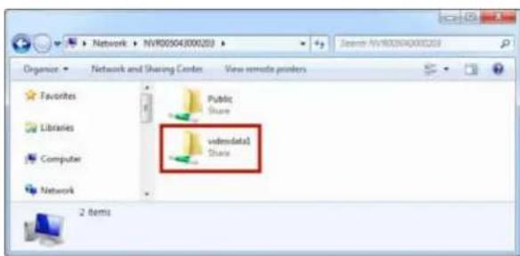
4) You will see two folders: Public and videodata1. Select videodata1 to check video files.
Linksys
Introduction
5 Video files are organized chronologically by recording date. Five-minute video files are sorted chronologically in each folder. Select a video file to play.
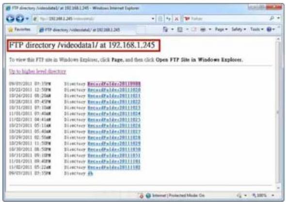
Find my record video files with FTP services
1) Type the following address in the browser's bar: "ftp://
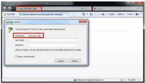
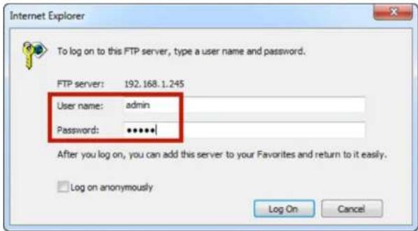
2) Log in with a User name and Password. If you haven't changed them, the User name and Password are "admin" and "admin." Click Log On.
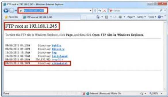
3) You will see a list of directories (folders). Select videodata1.
Linksys
Introduction
4) Video files are organized chronologically by recording date. Five-minute video files are sorted chronologically in each directory/folder. Select a video file to play.
Configuration
You can configure IP Camera, Recording & Event, Disk Management, Network, Management and System from drop-down menus on the Configuration page.
Camera Settings
Your NVR provides two options for adding cameras: Settings and UPnP Search.
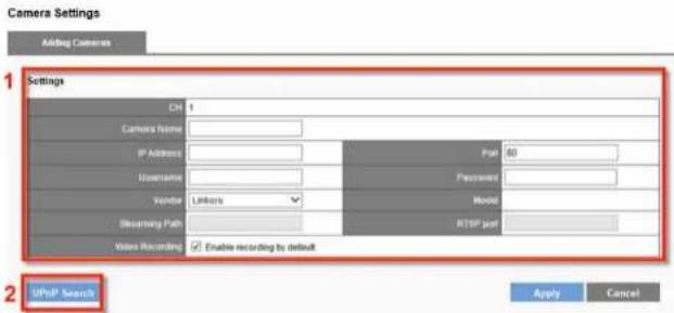
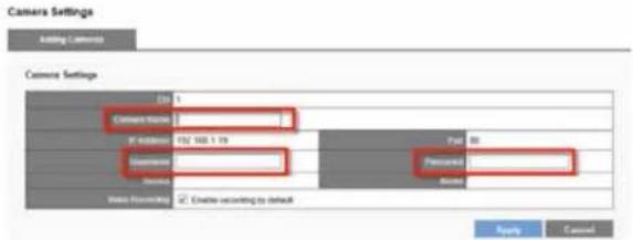
Manually Adding Camera:
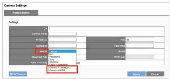
1) Enter a Camera Name, IP Address, Username, Vendor and Password.
2) If you select Generic RTSP or Generic MJPEG in the Vendor field, enter Streaming Path column with proper RTSP or MJPEG URLs. If Generic RTSP is selected, RTSP port should be filled out too.
NOTE
The most correct URLs should be provided from each camera vendors.
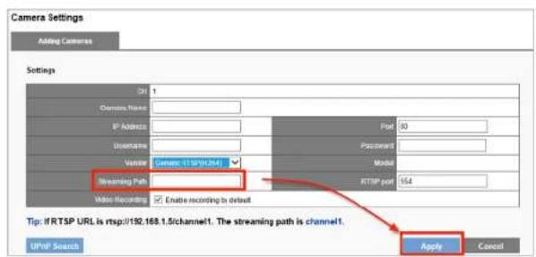
3) Click Apply.
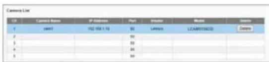
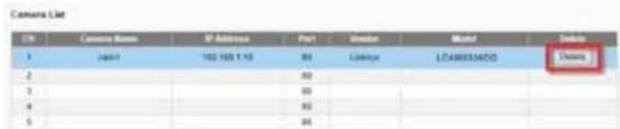
4) All added cameras appear in Camera List.
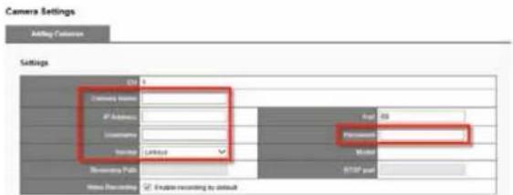
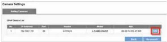
Adding Camera with UPnP Search
1) Click UPnP Search to find UPnP devices in your LAN.
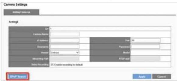
2) Available cameras will be displayed. Click Add to add the camera.
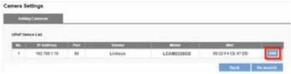
NOTE
Your network camera must to be UPnP enabled. Check with your camera supplier on how to enable UPnP.
3) Manually enter Camera Name, Username and Password and click Apply.
4) Once you have added all your cameras, click Back to return to the Camera Settings page and check your Camera List.
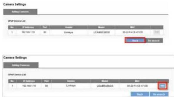
5) Users can refresh UPnP device list by clicking Re-search
Delete
To delete a camera from the list, select the row and click Delete.
Video Settings
Your NVR supports multi-stream monitoring and recording. You can modify settings such as video format, frame rate, resolution and video quality.
Configure Camera Video Settings
The row of the camera you choose will be highlighted. The window below will appear with settings to configure multi-stream.
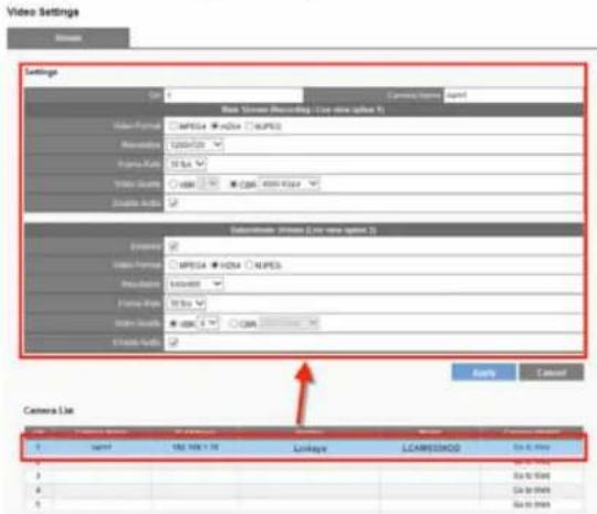
Video Format - Choose a video compression format for live view and recording: MPEG4, H.264 and MJPEG.
NOTE
Video formats vary depending on the camera brands and models.
Frame Rate - Select frame rate from drop-down list. The network environment will influence frame rate of IP camera.
Resolution - Select resolution from drop-down list.
Video Quality - Select VBR (Variable Bit Rate) or CBR (Constant Bit Rate).
Enable Audio - Enable or disable audio recording function.
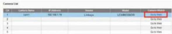
Go to Web - For advanced settings, click Go to Web to access your camera's Web configuration interface.
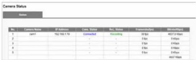
Camera Status
Shows status of connection to NVR, recording status, framerate (fps), bitrate (Kbps).
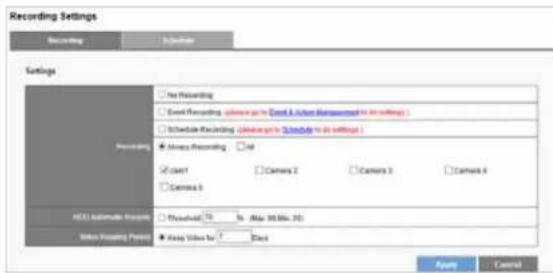
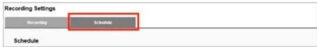
Recording Settings
Recording & Event provides different modes and recording schedules for you to configure your IP camera.
Linksys
Configuration
No Recording - Recording will be disabled on all cameras.
Event Recording - Enables the scheduling of a time to record video. The schedule can be configured in the Schedule tab.
Always Recording - Select a camera or check All. Selected cameras will record video continuously.
Your NVR provides two ways to delete recorded videos
- HDD Automatic Recycle: Overwrites oldest video files automatically when saved data hits assigned threshold. Maximum threshold is 90%; minimum is 20%. For example, if you set the threshold at 70%, the oldest files on the HDD will be deleted when data stored is 70% of capacity.
- Video Keeping Period: Set a time period for keeping videos. For example, if the period is seven days NVR will automatically delete videos older than seven days.
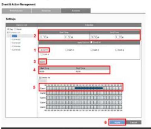
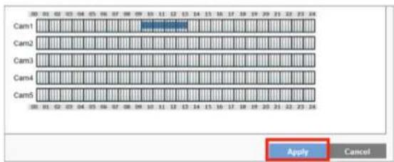
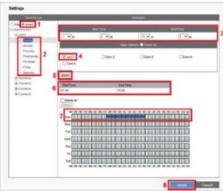
Schedule
Define time ranges in Event Recording for all cameras.
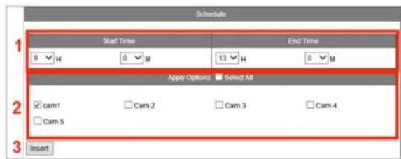
1) Select a camera and set the schedule.
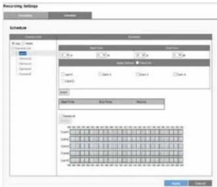
2) Choose start/end time and camera(s) to set a recording schedule. Click Insert.
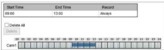
3) A time bar shows the scheduled time for all cameras.
4) If you want to set more than one schedule, repeat process to insert more schedules for the same camera.
5) Click Apply to finish setting the schedule or Cancel to adjust the schedule.
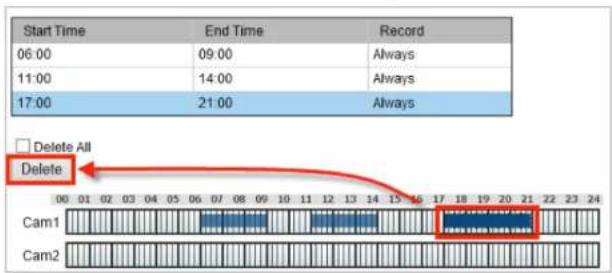
Delete - Erase a specific time in a recording schedule by selecting the time in the schedule table for a camera and clicking Delete.
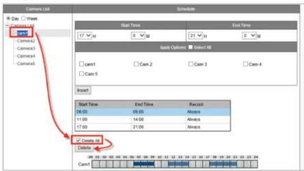
Delete All - Delete all scheduled recordings for a camera by selecting the camera from the Camera List, checking the Delete All box and clicking Delete.
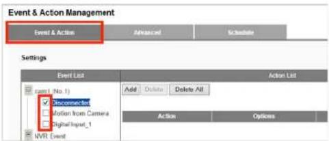
Event & Action Management
With Event & Action Management, you can arrange for the NVR to perform certain actions, including notifying you, when an event occurs with an IP camera.
Event List
- Disconnected - The action will be triggered if the selected camera loses connection with the NVR.
- Motion from Camera - Your selected actions will be triggered once motion is detected.
• Digital Input - Your selected actions will be triggered once Digital Input is detected. - NVR event (Disconnected) - If your NVR loses its network connection, Digital Output will be triggered.
- NVR event (Recording Error) - If your NVR fails to record, it will send you an email notification.
- External HTTP Event - Event could be triggered by external HTTP-in CGI command. You can define up to five different HTTP-in events. Set actions just like other events.
The format of external HTTP event CGI: http://
is defined for the number (1\~5) of external HTTP-in events that need to be triggered.
For example:
http://192.168.1.245/login.cgi/cgi_main.cgi?cgiName=event_ipc.cgi&eventName=Defined_3
The CGI sends a message to the NVR with IP 192.168.1.245 and triggers external event #3.
Actions List
Check an event type and click Add to create an action.
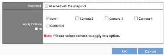
- Send Email - The NVR will send an email every 20 seconds during the event. So, if an event lasts one minute, your NVR will send three emails.
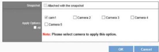
Attached with the snapshot - Email will be sent with snapshot of the event.
Apply Options - To select cameras to apply this action.
Digital Output
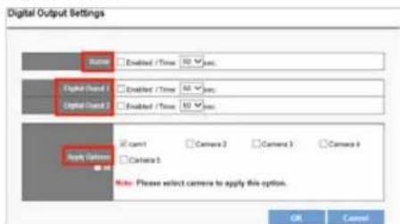
Buzzer - Can be enabled to sound for up to 60 seconds.
Digital Output1 and 2 - Supported by other digital outputs of the server and can be enabled for up to 60 seconds.
Apply Options - Select cameras to apply this action.
- User Defined Action - Send a specific HTTP command when an event is triggered, allowing you to manage devices such as power controller, fire/smoke protection device.
• Event Trigger Record
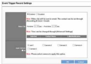
Video Clip - A video clip will be sent by email. In the Advanced tab, you can change the number of seconds before and after the event triggers that you want to be included in the clip.
Apply Options - Select cameras that you want to record video clips at the event trigger.
Advanced
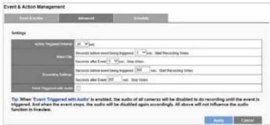
Action Triggered Interval - Set the amount of time that the NVR must wait between triggered events. Set an interval time during each events are triggered in sequence.
Video Clip and Recording Settings - You can change the number of seconds before and after the event trigger that you wish included in the clip. Video clips can include as many as 300 seconds before the event is triggered, and up to 300 seconds after the event ends.
Linksys
Configuration
Event Triggered with Audio - You may record audio only when an event is triggered. When the event stops, the audio will be disabled again automatically.
Schedule
Set up event detection for a certain time period.
1) Enable the event detection.
NOTE
Event schedules automatically start in "always" mode.
2) Go to the Schedule tab.
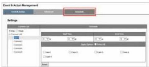
3) Select Day or Week schedule.
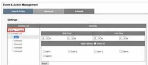
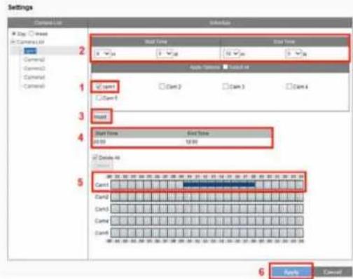
By Day
- Select the camera.
- Designate the time period.
- Click Insert.
- Designated duration is displayed.
- Designated duration is shown on chart.
- Press Apply.
By Week
- Select the Week for the specific recording schedule.
- Designate the time period.
- Select the camera and Click Insert.
- The designated duration is displayed.
- The designated duration is shown in chart.
- Click Apply.
4) Click Apply to apply the settings.
Remove event schedule
1) Designate the time period on chart by clicking on it.
2) Click Delete.
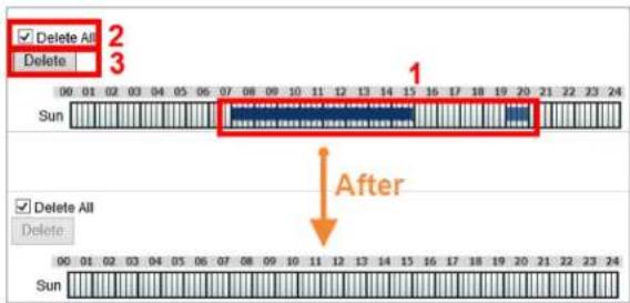
Remove all event periods in one camera
1) Click any period of the camera.
2) Check Delete All.
3) Click Delete.
E-Mail Settings
Setup
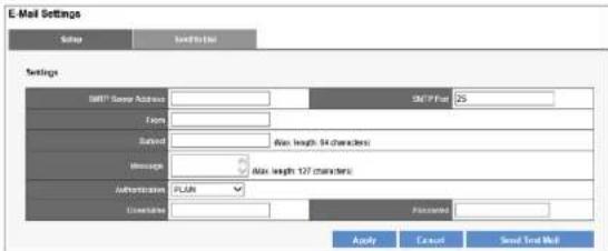
SMTP Server Address - Enter the Server Address of the SMTP server.
From - Specify sender's email address in the Sender field.
Subject - Enter the email subject.
Message - Enter the email content.
Authentication - Depending on the mail server, SMTP Server provides three types of authentication. Select PLAIN, LOGIN, or LOGIN with TLS.
Username - Specify username.
Password - Specify user password.
Send Test Mail - Test your email settings.
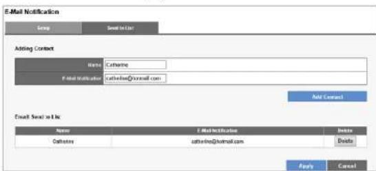
Send to List
Add Contact - Add contact you like the email to be sent.
Email Send to List – Display the contact list.
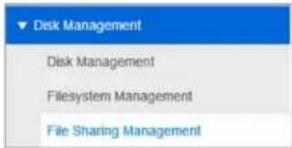
Disk Management
Disk Information provides details of the hard disk drive: Slot Number, HDD Model, Serial No., Capacity and Status.
Creating a new RAID Disk
1) Click Create tab to create a New RAID Disk.
![Quick Configuration - Disk Management Disk Information Create New SAG Disk Free HDDs R/WOMF (F) [HIS LUX] Assigned HDDs](/content/2026/05/773384/images/55c70ef603087a0bb37531120ae6148c5697bc4febb3b62badcbd3168565cdd9.jpg)
2) The selected hard disk drive will be marked in blue. Click to move the hard disk drive into the Assigned HDDs field.
3) The selected hard disk drive in Assigned HDDs field will be marked in blue.
![Price HOCs Aligned HOCs 100% of last 100% Big Drive(Linear) [405-08] Performance(Radd) [405-08] Fault Tender(Radd) [0-08] Fault Tender(Radd) [0-08] Apply Cancel](/content/2026/05/773384/images/65722c149cb781547d86416e11aa5bef92fdfb0603a51ba7123e5ac3ae70546e.jpg)
4) You can choose from four types of disk configuration. Choose a disk configuration and click Apply to configure the RAID disk.
![Quick Configuration - Disk Management Data Information Create Create New RMS Disk Free HDDs Assigned HDDs Input of 100% off Output Available RMS Disk ● Big Drive(Litter) [465 GB] ○ Performance(Class) [465 GB] ○ Fault Tolerance(Rash) [0 GB] ○ Fault Tolerance(Class) [0 GB] Ready... Cancel](/content/2026/05/773384/images/44b3ac4ac97db5fff29205bf09b24f3fe2f2f6aef57a9eb4ca2a47274959b811.jpg)
| Big Drive (Linear) Big Drive is a collection of hard disk drives and does not provide any RAID protection. The data are written to the disks continuously. | |
| Performance (RAID0) RAID0 combines two or more hard disk drives to function as one larger volume. Data are written to the hard disk drives without any parity information. Total storage capacity is the sum of all hard disk drives. | |
| Fault Tolerant (RAID1) A | RAID1 array requires two hard disk drives. RAID1 provides disk mirroring by duplicating the data between two hard disk drives. |
Fault Tolerant (RAID5)
A RAID5 array requires a three or more hard disk drives. Data are striped in all hard drives in a RAID5 array, and parity information is stored in each drive. If a hard disk drive fails, the array enters degraded mode. The data can be rebuilt from other member drives after installing a new drive to replace the failed one.
5) Configuration progress is tracked in the Disk Information window. When formatting progress reaches 100%, configuration mode switches to "create swap."
NOTE
Don't turn off the server or unplug any hard drives when RAID Disk configuration is in process.
6) When progress reads, "none," the RAID disk configuration is complete. After the RAID disk is created, RAID Disk List shows details about the disk: RAID Name, RAID type, Capacity, Status, Action State, Background Activity, Estimated Time and Progress.
File System Management
The filesystem information will show the volume of the RAID as below. Filesystem is a way to organize data you will need after a program is terminated. It provides procedures to store, retrieve and update data, as well as to manage the available space on the device.
![Filesystem Management Information Filesystem 12 Filesystem List Volume: [408 AA GE RAD A] Filesystem Information Name: Volume1 Capacity: 475.64.125 New Date Range: 2.98.08, 6.52% Date: RAD A Status: Statused](/content/2026/05/773384/images/e3c98d9edd6ca6df5793f8fd052c28bbf7d357808fa198d976acbbc78635aa29.jpg)
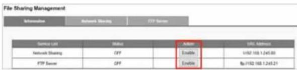
File Sharing Service
Arrange data transmission service including Windows Networking and FTP service.
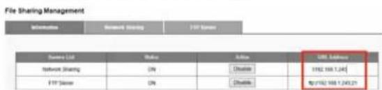
Information
Once the hard disk is installed, the filesystem will show status as below. Enable or Disable a sharing service to turn On/OFF Windows Networking and FTP service.
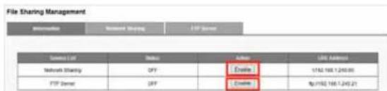
When a service is enabled, you can open dialog windows in a browser or Windows Explorer using the URL Address.
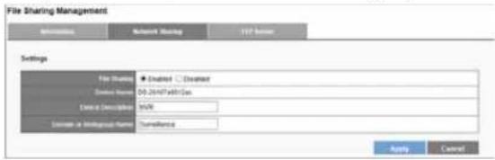
Network Sharing
In Network Sharing tab, you can enable or disable file sharing services, or change Device Description and Domain or Workgroup Name.
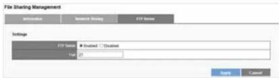
FTP Server
You can enable or disable the FTP Server and change the port. Click Apply to save any changes.
Network Setup
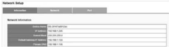
Information
Network information displays your network configuration: Device Name, IP Address, Subnet Mask, Default Gateway IP Address, and Primary DNS.
Network
You can rename the device and decide the Network Connection Type
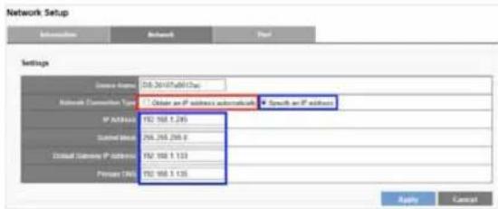
- Obtain an IP address automatically
Obtain an available dynamic IP address assigned by a DHCP server. Your NVR will automatically obtain an available dynamic IP address from the DHCP server when connecting to the LAN.
- Specify an IP address
If no DHCP server exists in the networking environment, the IP address will be given as 192.168.1.245. It should be sufficient in most network environments, and users can maintain the default IP address or alter IP address in this page. However, it's recommended to set a different IP address if there is more than one NVR in the network.
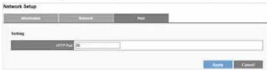
Port
You can configure an HTTP port here. The default port is 80.
Network Management
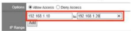
IP Filter
1) Select Allow Access or Deny Access to specified IP addresses.
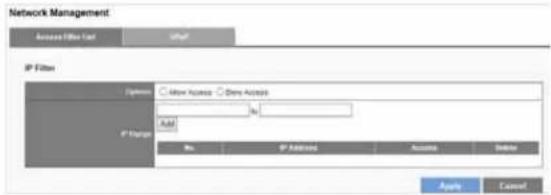
2) Enter an IP address range to allow or deny access.
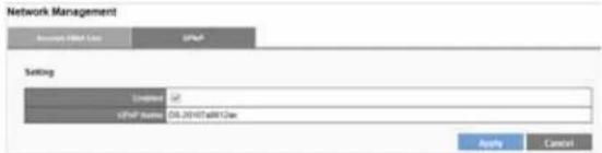
UPnP
UPnP field displays UPnP name. You can enable or disable UPnP search.
DDNS
DDNS links a domain name to an IP address, allowing you to easily access your cameras even with a changing IP address. Your NVR is compatible with two DDNS service providers: DynDNS and No-IP.
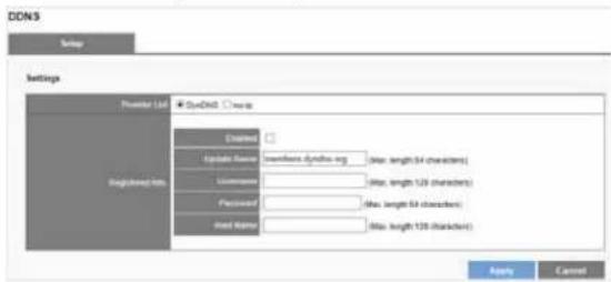
NOTE
Before utilizing this function, please apply for a dynamic domain account from a DDNS provider.
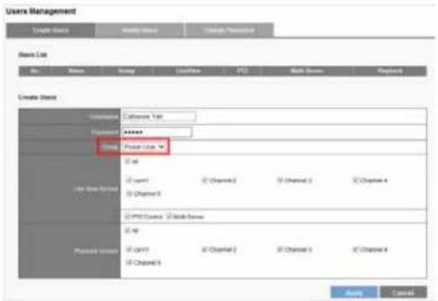
User Management
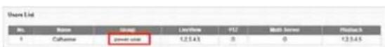
Multiple users can access the NVR simultaneously. The built-in Administrator account (user name "admin" and password "admin") creates other user accounts. Administrator has the highest privilege compared to Power User and User. And Power User and User can be given different privileges for live view and playback of different channels.
Create Users
1) Enter a username and password.
2) Select the users from the Group drop-down list.
3) Check liveView Access and Playback access.
4) Click Apply.
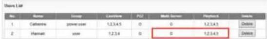
After the Power User is created, Users List will display the information as below.
Modify Users
1) Select a user to modify. The selected account will be highlighted.
2) Modify the user settings
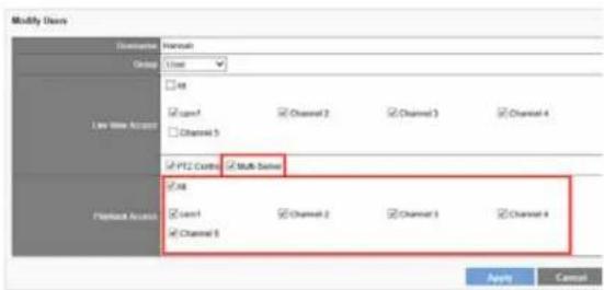
3) Click Apply.
Delete Users
To delete the user account, click Delete.
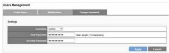
Change Password
Each NVR comes with a built-in admin account with password "admin." You should change the password upon the initial login. Select an account from the Username drop-down list to change the password.
1) Enter a new password in the New Password field
2) Enter it again in the Retype Password field.
3) Click Apply.
Log System
Log System records the activity on the NVR, and provides basic information for troubleshooting. There are six types of logs: Hardware Log, NVR Log, Event Log, Current User, History of User and File Access Log.
Hardware Log
Log information: RAID creation, RAID deletion, RAID modification, CPU, buzzer, fan, system, sensor and USB.
Log System
| Date & Time | Level | Message |
| 2019/12/08 14:41:58 | notice | [IMAGE] enable buzzer notice |
| 2019/12/08 14:41:56 | notice | [IMAGE] enable fan control. |
| 2019/12/07 11:44:54 | info | [IMAGE] System is starting to work. |
| 2019/12/07 11:44:54 | notice | [IMAGE] enable buzzer notice |
| 2019/12/07 11:44:54 | notice | [IMAGE] enable fan control. |
| 2019/12/07 11:44:54 | info | [IMAGE] System is starting to work. |
| 2019/12/06 17:02:20 | notice | [IMAGE] RAID deleted. |
| 2019/12/06 18:58:13 | notice | [IMAGE] RAID creation finished. |
| 2019/12/06 19:05:51 | notice | [IMAGE] RAID creation started. |
| 2019/12/06 18:30:13 | notice | [IMAGE] RAID deleted. |
| 2019/12/06 19:07:53 | notice | [IMAGE] RAID creation finished. |
| 2019/12/06 19:05:30 | notice | [IMAGE] RAID creation started. |
| 2019/12/06 15:48:47 | notice | [IMAGE] HDD at stock 2 is attached. |
| 2019/12/06 15:03:01 | notice | [IMAGE] enable buzzer notice |
| 2019/12/06 15:03:01 | notice | [IMAGE] enable fan control. |
| 2019/12/06 15:03:01 | info | [IMAGE] System is starting to work. |
| 2019/12/06 11:02:49 | notice | [IMAGE] system powerofftriggers by power button. |
| 2019/12/06 11:02:36 | notice | [IMAGE] system powerofftriggers by power button. |
| 2019/12/06 10:58:06 | notice | [IMAGE] system powerofftriggers by power button. |
| 2019/04/03 19:20:03 | notice | [IMAGE] system powerofftriggers by power button. |
NVR Log
Log information: time zone, daylight, system, firmware upgrading, configuration IP, recording files export, and storage.
Log System
| Date: 04 | Level: 03 | Page: 1 | Next Page | Formed Item | History of Time | File Access Log | |
| Item & Type | Largest | Access | IP Address | Methods | |||
| 2015/12/30 | 14:41:38 | info | SYSTEM | Locushful | (NWR) System is clearly for starting up. | ||
| 2015/12/27 | 18:37:32 | indoor | SYSTEM | Locushful | (NWR) System is shaking down. | ||
| 2015/12/27 | 11:44:54 | info | SYSTEM | Locushful | (NWR) System is clearly for starting up. | ||
| 2015/12/27 | 19:05:09 | info | SYSTEM | Locushful | (NWR) System is shaking down. | ||
| 2015/12/26 | 19:03:01 | info | SYSTEM | Locushful | (NWR) System is clearly for starting up. | ||
| 2015/12/26 | 19:01:52 | indoor | SYSTEM | Locushful | (NWR) Software upgrading. | ||
| 2015/12/26 | 14:35:26 | indoor | SYSTEM | Locushful | (NWR) Software upgrading. | ||
| 2015/12/26 | 13:13:26 | indoor | SYSTEM | Locushful | (NWR) Software upgrading. | ||
| 2015/12/26 | 12:33:15 | info | SYSTEM | Locushful | (NWR) The IP is been changed = 102, 168, 1, 245+ | ||
| 2015/12/26 | 11:02:34 | info | SYSTEM | Locushful | (NWR) Storage is randomly unable to handle log file. | ||
| 2015/12/26 | 10:40:07 | info | SYSTEM | Locushful | (NWR) The IP is been changed = 102, 168, 1, 11+ | ||
| 2015/12/26 | 10:40:18 | info | SYSTEM | Locushful | (NWR) The IP is being changed = 102, 168, 1, 11+ | ||
| 2015/12/26 | 10:41:26 | info | SYSTEM | Locushful | (NWR) Storage is randomly unable to handle log file. | ||
| 2015/12/26 | 10:50:54 | info | SYSTEM | Locushful | (NWR) This IP is been changed = 102, 168, 1, 245+ | ||
| 2015/10/12 | 14:40:08 | indoor | SYSTEM | Locushful | (NWR) System is shaking down. | ||
| 2015/10/12 | 12:37:38 | indoor | SYSTEM | Locushful | (NWR) System is shaking down. | ||
| 2015/10/11 | 10:44:22 | indoor | SYSTEM | Locushful | (NWR) System is reordering. | ||
| 2015/10/11 | 19:06:56 | info | SYSTEM | Locushful | (NWR) System is reordering. | ||
| 2015/10/11 | 11:47:22 | indoor | SYSTEM | Locushful | (NWR) Software upgrading. | ||
| 2015/10/08 | 11:23:08 | info | SYSTEM | Locushful | (NWR) The system time is configured. | ||
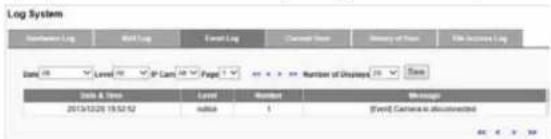
Event Log
Log information: Camera is connected, Camera is disconnected, Digital Input, Motion detected and Storage usage is out of limit, etc.
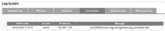
Current User
Log information: users logged in to the NVR with an IP address.
History of User
Log records activity of any user who has logged in to the NVR.
Log System
| Date & Time | Level | Account | IP Address | Method | Message |
| 2013/12/30 18:20:26 | info | admin | 152.168.1.144 | HTTP | [USER] Account [Hannett] is configured. |
| 2013/12/30 18:18:13 | info | admin | 152.168.1.144 | HTTP | [USER] Account [Hannett] is created. |
| 2013/12/30 18:15:29 | info | admin | 152.168.1.144 | HTTP | [USER] Account [Hannett] is deleted. |
| 2013/12/30 18:15:11 | info | admin | 152.168.1.144 | HTTP | [USER] Account [Hannett] is created. |
| 2013/12/30 18:14:31 | info | admin | 152.168.1.144 | HTTP | [USER] Account [Hannett] is deleted. |
| 2013/12/30 18:14:26 | info | admin | 152.168.1.144 | HTTP | [USER] Account [Hannett] is created. |
| 2013/12/30 18:14:17 | info | admin | 152.168.1.144 | HTTP | [USER] Login |
| 2013/12/30 18:14:17 | info | admin | 152.168.1.144 | HTTP | [USER] Login |
| 2013/12/30 18:03:38 | info | admin | 152.168.1.144 | HTTP | [USER] Account [Cathernel] is created. |
| 2013/12/30 15:25:05 | info | admin | 152.168.1.144 | HTTP | [USER] Login |
| 2013/12/30 15:25:05 | info | admin | 152.168.1.144 | HTTP | [USER] Login |
| 2013/12/30 15:08:15 | info | admin | 152.168.1.144 | HTTP | [USER] Enable Windows networking service. |
| 2013/12/30 15:09:13 | info | admin | 152.168.1.144 | HTTP | [USER] Enable FTP service. |
| 2013/12/30 15:07:32 | info | admin | 152.168.1.144 | HTTP | [USER] Enable FTP service. |
| 2013/12/30 15:07:30 | info | admin | 152.168.1.144 | HTTP | [USER] Enable Windows networking service. |
| 2013/12/30 14:58:22 | info | admin | 152.168.1.144 | HTTP | [USER] Enable FTP service. |
File Access Log
Log records access to your NVR through methods other than HTTP (SAMBA or FTP).
![Log System Network Log MVI Log Contact Log Contact Date History of User File Access Log Date All Level All Page 1 Number of Dqgsbys 20 Name Address Name Location Account IP Address Method Message Address 20/3/20/20 15:13:26 info admin 192 168.1.44 FTP [STOCKE] Login Pass 20/3/20/20 15:13:26 info admin 192 168.1.44 FTP [STOCKE] Login Pass 20/3/20/20 15:22:22 info admin 192 168.1.44 SAMBA [STOCKE] Login Pass 20/3/20/20 15:09:25 info admin 192 168.1.4 SAMBA [STOCKE] config.daf Access 20/3/20/20 15:09:26 info admin 192 168.1.4 SAMBA [STOCKE] config.daf Access 20/3/20/20 15:09:26 info admin 192 168.1.4 SAMBA [STOCKE] Login Pass](/content/2026/05/773384/images/3e1b0da959289bcfa10da8604375effa7ef7cdcfcee14779b018619435039a18.jpg)
Export log files
Users can export and save log files from the Log System page by clicking.
![Log System Name: Log Date: 18 Level: 40 Page: 1 Number of Displays: 20 Status Data & Time Level Message 2013/12/06 14:41:58 notice [NET] update your online 2013/12/06 14:41:58 notice [NET] update your online](/content/2026/05/773384/images/14f42e6bf850eb1cff2ba5a95e8b5ee525795bfb334f1db65081ecb6c92ec151.jpg)
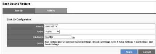
Back Up and Restore
Back Up Configuration
Select Volume and Folder, and specify the File Name to save configuration as a configuration (.cfg) file. Back up Configuration will just save Camera Setting, Recording Settings, Event & Action Settings, E-Mail settings, and Server Settings.
NOTE
The configuration file is saved in your NVR's Public folder. You can access the folder with Windows Networking or FTP service.
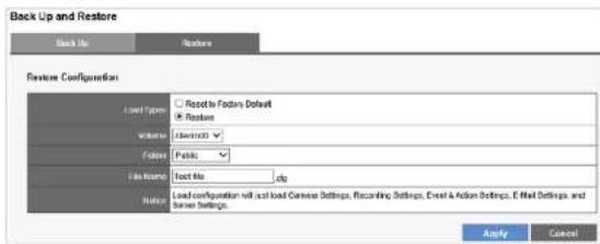
Restore Configuration and Factory Default
Restore Configuration can duplicate settings from one NVR to another without a manual configuration.
1) Select "Reset to Factory Default" to reset the NVR to its original state or select "Restore" to restore the settings from configuration file.
2) Leave volume and folder default settings.
3) Enter the name of the configuration file to restore.
NOTE
The configuration file needs to be located in NVR's public folder before you can restore it. You can access the folder with Windows Networking or FTP service.
4) Click Apply.
Data Backup
You can preset a quick backup of the most recent duration and channels to back up on Remote Web Browser. This will save the latest video files locally. When set, all you need to do is connect a USB device to the NVR (front panel backup area) and press and hold the BACKUP button above the USB port for three seconds.
During the backup process, the USB LED indicator will blink blue. When the backup completes, the blue light will fade.
NOTE
- USB device format must be FAT32 file system.
- NVRPlayer and NVRCheck will be saved with the video files.
• NVRPlayer is the player of NVR recording file. - NVRCheck is a tool to verify the files were recorded on the NVR.
Backup Settings
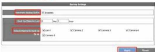
Hardware Backup Button - Enabled or disable for security concerns.
Back Up Video for Last - Set a maximum of days and hours to back up the latest video files.
Select Channel to Back Up – Choose cameras or check All.
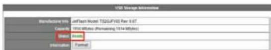
Operating Data Backup
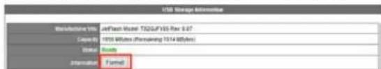
When the USB device is ready, the USB Storage Information screen will show: Ready, and the USB LED indicator will be blue.
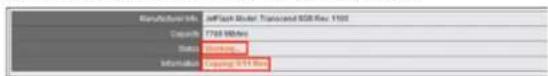
While the backup is in progress, the USB Storage Information screen will show: Working, and Information: Copying: ...files.
To delete the current data on your USB drive, click Format.
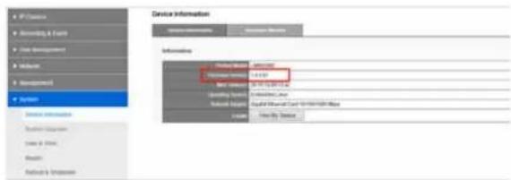
Device Information
System Information
The System Information tab shows Product Model, Firmware Version, NVR Address, Operating System and Network Adapter.
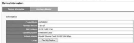
Locate - Click Find My Device, and the NVR buzzer will sound for three seconds to help you locate your NVR.
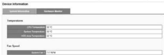
Hardware Monitor
The Hardware Monitor tab shows Temperatures and Fan Speed.
System Upgrade
1) Download the latest firmware file and save to a local computer.
2) Press Browse and navigate to where you saved the firmware file.
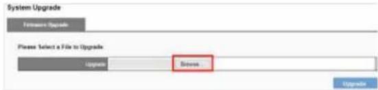
3) Select the file, and click Upgrade.
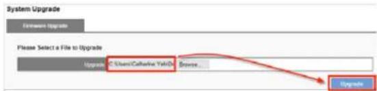
4) When the upgrade is finished, your NVR will reboot.
5) Go to Device Information from the System drop-down list and check NVR firmware version.
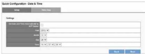
Date &Time
Setup
Configure your device's date and time. You can have the NVR automatically set date and time with NTP server or you can configure it manually. To have the NVR set date the time, click the Time Zone tab and choose the time zone of your area.
NOTE
Verifying and adjusting current local time and daylight saving time will help you avoid the following errors:
• Incorrect display time for playback videos.
• Inconsistent display time of event logs and when they actually occur.
Time Zone
Set the time and date for your time zone, and choose whether to automatically adjust for daylight saving changes.
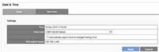
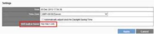
Built-in NTP server in NVR
Your NVR allows client devices to synchronize with the time clock. This helps to maintain a consistent time schedule in your surveillance system. The built-in NTP server address is your NVR's IP address.
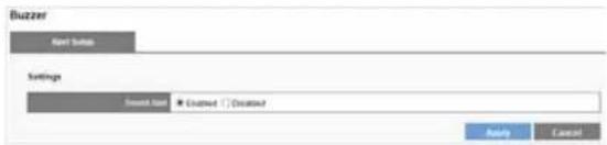
Buzzer
Enabled or disable to set the Sound Alert.
NotE
To stop the buzzer sound when it occurs, press the BACKUP button on the front panel of your NVR for one second.
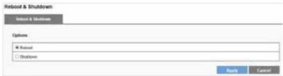
Reboot & Shutdown
Select Reboot to restart the NVR or select Shutdown to turn off the NVR.
Specifications
Model No.: LNR0208C
Hardware
CPU
Processor
Marvell
General
Memory:
1GB
HDD capacity Up to 8TB (storage capacity per HDD up to 4TB)
HDD tray 2 x hot-swappable and lockable tray with
K-Lock security slot for theft prevention
LAN port 1 x Gigabit RJ-45 Ethernet port
LED Indicators HDD 1, HDD 2, eSATA, LAN
USB connectors 3 x USB 2.0:
One in front for video backup, two in back are reserved for future enhancement
External eSATA 2 x eSATA ports
Buttons Power, USB backup
DI/DO 4 in, 2 out
Alarm buzzer System Warning
Form Factor Tower
Power supply External power adaptor, 60W
Input: 100-240V
Power consumption Operation: 15.9\~20.8W (With 2 x 500GB HDD
installed and in RAID 1 building process)
Environment
Operating temperature 0°C \~ 40°C
Operating humidity 0% \~ 95% R.H
Build-in fans 1 x quiet cooling fan
Compliance Information
FCC/IC FCC/IC
CE CE
Major features list
Supported Channels Up to 8
Video Compression H.264/MJPEG/MPEG-4
(Depending on the camera)
Maximum Throughput 150Mbps
Disk Management JBOD/Linear, RAID0, RAID1 and RAID5
Event Management Connection lost, Motion detection, External HTTP, Digital Input
Action Management Event recording, E-mail notification, Digital Output, User-defined Action
Services SMB/CIFS and FTP
Video Backup USB Port
RemoteLiveView Y
Remote Playback Y
Video Recording Y
System Log Y
User Management Y
ONVIF Supported Y
Dimensions
Unit Dimension 246.1(D) x 114.97(W) x 164.94(H) mm
9.69(D) × 4.53(W) × 6.49(H) inch
Unit Weight (kg) 2.09kg
NOTE
- For regulatory, warranty, and safety information, see the enclosed CD or go to Linksys.com/business
• Documentation is subject to change without notice
Visit linksys.com/support for award-winning technical support
© 2014 Belkin International, Inc. and/or its affiliates. All rights reserved. BELKIN, LINKSYS and many product names and logos are trademarks of the Belkin group of companies. Third party trademarks mentioned are the property of their respective owners.
8820 01868 Rev. ACO

- Introduction
- Before You Use This Product
- NotE
- Hardware Description
- LED Indicators Status
- How to Access Web Configuration
- Linksys
- Quick Configuration
- Start Quick Configuration
- LiveView
- Display mode
- Event Log Icon
- Option Icon
- - Multi-Server
- - Sequential Mode Setting
- - Joystick
- PTZ Control Panel
- Exchange Streaming
- De-warp for fisheye cameras
- De-warp for Immervision Lenses
- Multi-NVR server
- Playback
- Main Functions
- Mute
- Setting
- Video playback controls
- Play Speed Indicator
- Scale bar
- Seek bar
- Digital zoom
- Snapshot
- Change OSD (on-screen display) color and font size
- 1) Click Setting icon.
- 2) Click Color, select the OSD color and click OK.
- 3) Select font size from drop-down list and click OK.
- 4) The font size and color are changed on the playback screen.
- Video Playback
- Frame by Frame Playback
- Export Files
- Play Video Files Remotely
- Find my record video files with network sharing
- Find my record video files with FTP services
- Configuration
- Camera Settings
- Manually Adding Camera:
- Adding Camera with UPnP Search
- Delete
- Video Settings
- Configure Camera Video Settings
- Camera Status
- Recording Settings
- Your NVR provides two ways to delete recorded videos
- Schedule
- Event & Action Management
- For example:
- Actions List
- Advanced
- By Day
- By Week
- Remove event schedule
- Remove all event periods in one camera
- E-Mail Settings
- Setup
- Send to List
- Disk Management
- Creating a new RAID Disk
- Fault Tolerant (RAID5)
- File System Management
- File Sharing Service
- Information
- Network Sharing
- FTP Server
- Network Setup
- Network
- - Obtain an IP address automatically
- - Specify an IP address
- Port
- Network Management
- IP Filter
- UPnP
- DDNS
- User Management
- Create Users
- Modify Users
- Delete Users
- Change Password
- Log System
- Hardware Log
- NVR Log
- Event Log
- Current User
- History of User
- File Access Log
- Export log files
- Back Up and Restore
- Back Up Configuration
- Restore Configuration and Factory Default
- Data Backup
- Operating Data Backup
- Device Information
- System Information
- Hardware Monitor
- System Upgrade
- Date &Time
- Time Zone
- Built-in NTP server in NVR
- Buzzer
- Reboot & Shutdown
- Specifications
- Model No.: LNR0208C
- Hardware
- CPU
- General
- Environment
- Compliance Information
- Major features list
- Dimensions
Brand : LINKSYS
Model : LNR0208C
Category : Video recorder