
Lite NVR4208-8P - Video recorder Dahua Technology - Free user manual and instructions
Find the device manual for free Lite NVR4208-8P Dahua Technology in PDF.


| Product Type | Network Video Recorder (NVR) |
| Brand | Dahua Technology |
| Model | Lite NVR4208-8P |
| Channels | 8 channels |
| PoE Ports | 8 built-in PoE ports (IEEE 802.3af/at) |
| Recording Resolution | Up to 8MP (4K) for IP cameras |
| Video Compression | H.265 / H.264 |
| Hard Drive Support | 1 SATA HDD (up to 10TB) |
| Video Output | 1 HDMI (4K), 1 VGA (1080p) |
| Audio | 1-ch RCA input, 1-ch RCA output |
| Network Interface | 1 RJ45 10/100/1000 Mbps |
| Dimensions (W x D x H) | 260 x 230 x 48 mm |
| Weight | Approx. 1.5 kg (without HDD) |
| Power Supply | DC 48V, 1.5A (included) |
| Power Consumption | Less than 15W (without cameras) |
| Operating Temperature | -10°C to +55°C |
| Remote Access | Via Dahua Web, App (gDMSS/LDMSS), P2P |
| Maintenance | Clean with dry soft cloth; ensure ventilation |
| Safety | Do not block vents; use only included power adapter |
| Spare Parts | Power adapter, remote control (optional), rackmount kit (optional) |
| Reparability | Replaceable HDD; firmware updates available |
Frequently Asked Questions - Lite NVR4208-8P Dahua Technology
User questions about Lite NVR4208-8P Dahua Technology
0 question about this device. Answer the ones you know or ask your own.
Ask a new question about this device
Download the instructions for your Video recorder in PDF format for free! Find your manual Lite NVR4208-8P - Dahua Technology and take your electronic device back in hand. On this page are published all the documents necessary for the use of your device. Lite NVR4208-8P by Dahua Technology.
USER MANUAL Lite NVR4208-8P Dahua Technology
Dahua Network Video Recorder User's Manual
V 2.4.2
Table of Contents
1 Features and Specifications ....1
1.1 Overview....1
1.2 Features....1
1.3 Specifications....2
1.3.1 NVR100/100-P Series 2
1.3.2 NVR11/11-P Series....4
1.3.3 NVR21-S2/NVR21-P-S2/NVR21-8P-S2 Series....7
1.3.4 NVR11H/11H-P Series 9
1.3.5 NVR11HS Series....11
1.3.6 NVR21HS-S2/21HS-P-S2/21HS-8P-S2 Series....13
1.3.7 NVR41/41-P/41-8P/41-W Series 15
1.3.8 NVR41H/41H-P/41H-8P Series 17
1.3.9 NVR22-S2/22-P-S2/22-8P-S2 Series....18
1.3.10 NVR42N Series 20
1.3.11 NVR42/42-P/42-8P Series 22
1.3.12 NVR42-16P Series 23
1.3.13 NVR42-4K/42-8P-4K Series 25
1.3.14 NVR52-4KS2/52-8P-4KS2/52-16P-4KS2 Series 27
1.3.15 NVR44/44-8P/44-16P Series....29
1.3.16 NVR44-4K Series 31
1.3.17 NVR54-4KS2/54-16P-4KS2 Series 32
1.3.18 NVR48-4K Series 34
1.3.19 NVR58-4KS2/58-16P-4KS2 Series 36
1.3.20 NVR48/48-16P Series 37
1.3.21 NVR72/72-8P Series....39
1.3.22 NVR74/74-8P/74-16P Series....41
1.3.23 NVR78/78-16P/78-RH Series 43
1.3.24 NVR70/70-R Series....44
1.3.25 NVR42V-8P Series 46
2 Front Panel and Rear Panel 49
2.1 Front Panel 49
2.1.1 NVR11/11-P/41/41-P/41-W/21-S2/21-P-S2/21-8P-S2 Series....49
2.1.2 NVR11H/11H-P/41H/41H-P/41H-8P Series....49
2.1.3 NVR11HS Series....50
2.1.4 NVR41-8P Series....50
2.1.5 NVR42/42-P/42-8P/72/72-8P Series....51
2.1.6 NVR21HS-S2/21HS-P-S2/21HS-8P-S2/22-S2/22-P-S2/22-8P-S2 Series....52
2.1.7
NVR42-16P/42N/42-4K/42-8P-4K/44-4K/48-4K/52-4KS2/52-8P-4KS2/52-16P-4KS2/
54-4KS2/58-4KS2 Series....53
2.1.8 NVR44/44-8P/44-16P/74/74-8P/74-16P Series....54
2.1.9 NVR48/48-16P/78/78-16P Series 56
2.1.10 NVR78-RH Series 58
2.1.11 NVR70/70-R Series....60
2.1.12 NVR42V-8P Series....62
2.2 Rear Panel 63
2.2.1 NVR100/100-P Series 63
2.2.2 NVR11/11-P Series 64
2.2.3 NVR41/41-P/41-8P/41-W Series 65
2.2.4 NVR21-S2/21-P-S2/21-8P-S2 Series....67
2.2.5 NVR11H/11H-P/41H/41H-P/41H-8P Series 69
2.2.6 NVR11HS Series....70
2.2.7 NVR21HS-S2/21HS-P-S2/21HS-8P-S2 Series....71
2.2.8 NVR22-S2/22-P-S2/22-8P-S2 Series....72
2.2.9 NVR42/42N/42-P/42-8P/42-16P Series....73
2.2.10 NVR42-4K/52-4KS2/52-8P-4KS2/52-16P-4KS2 Series....75
2.2.11 NVR42-8P-4K Series....77
2.2.12 NVR44/44-8P/44-16P Series....79
2.2.13 NVR44-4K/48-4K/54-4KS2/58-4KS2/54-16P-4KS2/58-16P-4KS2 Series .....81
2.2.14 NVR48/48-16P Series 83
2.2.15 NVR72 Series 85
2.2.16 NVR72-8P Series 86
2.2.17 NVR74 Series 88
2.2.18 NVR74-8P/74-16P Series 90
2.2.19 NVR78 Series 92
2.2.20 NVR78-16P Series 93
2.2.21 NVR78-RH Series 95
2.2.22 NVR70 Series 97
2.2.23 NVR70-R Series....99
2.2.24 NVR42V-8P Series....101
2.3 Alarm Connection....102
2.3.1 Alarm Port....102
2.3.2 Alarm input port 103
2.3.3 Alarm input and output port....104
2.3.4 Alarm relay specifications ....104
2.4 Bidirectional talk 105
2.4.1 Device-end to PC-end 105
2.4.2 PC-end to the device-end 105
2.5 Mouse Operation....106
2.6 Remote Control 107
3 Device Installation....110
3.1 Check Unpacked NVR....110
3.2 About Front Panel and Rear Panel....110
3.3 HDD Installation....110
3.3.1 NVR100/100-P Series 110
3.3.2 NVR11/11-P/41/41-P/41-8P/41-W/21-S2/21-P-S2/21-8P-S2 Series....111
3.3.3 NVR11H/11H-P/41H/41H-P/41H-8P/11HS/21HS-S2/21HS-P-S2/21HS-8P-S2
Series 112
3.3.4
NVR42/42N/42-P/42-8P/42-16P/72/72-8P/42-4K/42-8P-4K/52-4KS2/52-8P-4KS2/52
-16P-4KS2/22-S2/22-P-S2/22-8P-S2 Series 113
3.3.5 NVR44/44-8P/44-16P/74/74-8P/74-16P/44-4K/54-4KS2/54-16P-4KS2 Series ..... 113
3.3.6 NVR48/48-16P/NVR78/78-16P/48-4K/58-4KS2/58-16P-4KS2 Series 114
3.3.7 NVR78-RH Series 115
3.3.8 NVR70/70-R Series....116
3.3.9 NVR42V-8P Series 117
3.4 CD-ROM Installation....117
3.5 Connection Sample....119
3.5.1 NVR100/NVR100-P Series 119
3.5.2 NVR11/11-P/41/41-P/41-8P/41-W/21-S2/21-P-S2/21-8P-S2 Series....119
3.5.3 NVR11H/11H-P/41H/41H-P/41H-8P Series....120
3.5.4 NVR11HS Series....121
3.5.5 NVR21HS-S2/21HS-P-S2/21HS-8P-S2 Series....122
3.5.6 NVR22-S2/22-P-S2/22-8P-S2 Series....123
3.5.7 NVR42N Series 124
3.5.8 NVR42/42-P/42-8P/42-16P/52-4KS2/52-8P-4KS2/52-16P-4KS2 Series....125
3.5.9 NVR42-4K Series 125
3.5.10 NVR42-8P-4K Series 126
3.5.11 NVR44-4K/48-4K/54-4KS2/54-16P-4KS2/58-4KS2/58-16P-4KS2 Series .....126
3.5.12 NVR44/44-8P/44-16P Series....127
3.5.13 NVR48/48-16P Series 128
3.5.14 NVR72 Series 129
3.5.15 NVR72-8P Series 129
3.5.16 NVR74 Series 130
3.5.17 NVR74-8P/74-16P Series 131
3.5.18 NVR78 Series 132
3.5.19 NVR78-16P Series....133
3.5.20 NVR78-RH Series 134
3.5.21 NVR70 Series 135
3.5.22 NVR70-R Series....136
3.5.23 NVR42V-8P Series 137
4 Local Basic Operation 139
4.1 Boot up and Shutdown....139
4.1.1 Boot up....139
4.1.2 Shutdown....139
4.2 Change/Reset Password 139
4.2.1 Change Password....139
4.2.2 Reset Password....140
4.3 Startup Wizard....141
4.4 Navigation Bar 145
4.4.1 Main Menu....146
4.4.2 Dual-screen operation 146
4.4.3 Output Screen....146
4.4.4 Tour....146
4.4.5 PTZ....146
4.4.6 Color....146
4.4.7 Search....146
4.4.8 Alarm Status....146
4.4.9 Channel Info....147
4.4.10 Remote Device 147
4.4.11 Network....147
4.4.12 HDD Manager....147
4.4.13 USB Manager....147
4.5 Smart Add....147
4.6 Remote Device 151
4.6.1 Remote Device Connection....151
4.6.2 Short-Cut Menu 152
4.6.3 Image 153
4.6.4 Channel Name....154
4.6.5 Upgrade....155
4.6.6 UPNP 156
4.6.7 Built-in Switch Setup....156
4.7 Preview....157
4.7.1 Preview 157
4.7.2 Preview control interface....158
4.7.3 Right Click Menu 159
4.7.4 Preview Display Effect Setup 160
4.7.4.1 Video Color....160
4.7.4.2 Display 162
4.7.4.3 TV adjust....163
4.7.5 Preview Tour Parameters ....163
4.8 Fish eye (Optional)....164
4.8.1 Fish eye de-warp during preview interface....164
4.8.2 Fish eye de-warp during playback....167
4.9 PTZ....167
4.9.1 PTZ Settings....167
4.9.2 PTZ Control....168
4.9.2.1 PTZ Function Setup....170
4.9.2.2 Call PTZ Function....173
4.10 Record and Snapshot....174
4.10.1 Encode....174
4.10.1.1 Encode....174
4.10.1.2 Overlay....175
4.10.1.3 Snapshot....176
4.10.2 Schedule....177
4.10.2.1 Schedule Record....177
4.10.2.2 Schedule Snapshot....180
4.10.3 Motion detect record/snapshot....182
4.10.3.1 Motion detect record....182
4.10.3.2 Motion Detect Snapshot....184
4.10.4 Alarm Record/Snapshot 185
4.10.4.1 Alarm Record....185
4.10.4.2 Alarm Snapshot....186
4.10.5 Manual Record/Snapshot....187
4.10.5.1 Manual Record 187
4.10.5.2 Manual Snapshot....188
4.10.6 Holiday Record/Snapshot 188
4.10.6.1 Holiday Record....188
4.10.6.2 Holiday Snapshot 190
4.10.7 Other Record/Snapshot....190
4.11 Playback and Search....190
4.11.1 Real-time Playback....190
4.11.2 Search Interface 191
4.11.2.1 Smart Search....195
4.11.2.2 Accurate playback by time....196
4.11.2.3 Mark Playback....196
4.11.3 Picture Playback....197
4.12 Backup....198
4.12.1 File Backup....198
4.12.2 Import/Export....199
4.12.3 Backup Log....200
4.12.4 USB Device Auto Pop-up....201
4.13 Alarm....202
4.13.1 Detect Alarm....202
4.13.1.1 Motion Detect....202
4.13.1.2 Tampering....206
4.13.1.3 Video Loss....207
4.13.2 IVS (Optional)....208
4.13.2.1 Tripwire (Optional) 208
4.13.2.2 Intrusion (Cross warning zone) (Optional) 212
4.13.2.3 Object Detect (Optional) 214
4.13.2.4 Scene Change (Optional) 215
4.13.3 Face Detect (Optional)....216
4.13.4 Audio Detect (Optional) 216
4.13.5 Alarm output....217
4.13.6 Alarm Setup....218
4.13.7 Abnormality....223
4.14 Network....225
4.14.1.1 TCP/IP 225
4.14.1.2 Connection 227
4.14.1.3 WIFI AP....228
4.14.1.4 WIFI 229
4.14.1.5 3G....230
4.14.1.6 PPPoE....231
4.14.1.7 DDNS 232
4.14.1.8 UPnP 234
4.14.1.9 IP Filter 235
4.14.1.10 Email....237
4.14.1.11 FTP 238
4.14.1.12 SNMP 240
4.14.1.13 Multicast....240
4.14.1.14 Alarm Centre 242
4.14.1.15 Auto register 242
4.14.1.16 P2P 243
4.14.1.17 Easy Space....245
4.14.1.18 SWITCH....246
4.14.2 Network Test....246
4.14.2.1 Network Test....246
4.14.2.2 Network Load....247
4.15 HDD Setup 248
4.15.1 Format....248
4.15.2 HDD Information....249
4.15.3 Advanced....251
4.15.4 HDD Detect 253
4.15.4.1 Manual Detect....254
4.15.4.2 Detect Report....254
4.15.5 RAID Manager....256
4.15.5.1 RAID Config 256
4.15.5.2 Hotspare disks 257
4.16 Basic Setups 258
4.16.1 Device Setup....258
4.16.2 Data and Time 259
4.16.3 Holiday 260
4.17 Device Maintenance and Manager....260
4.17.1 System Info....260
4.17.1.1 Version....260
4.17.1.2 BPS 261
4.17.1.3 Online User 261
4.17.1.4 Remote Device Information 262
4.17.1.5 Remote....263
4.17.1.5.1 Device Status....263
4.17.1.5.2 Firmware....264
4.17.2 Log....265
4.17.3 Voice....266
4.17.3.1.1 File Manage 266
4.17.3.1.2 Schedule....267
4.17.4 Account....267
4.17.4.1.1 Add User....269
4.17.4.1.2 Modify user....271
4.17.4.1.3 Change Password....271
4.17.4.1.4 Add/Modify Group 271
4.17.4.1.5 Security Question....273
4.17.5 Update....273
4.17.5.1 Local Update....273
4.17.5.2 Uboot....274
4.17.6 Default....274
4.17.7 RS232 275
4.17.8 Auto Maintain 276
4.17.9 Logout /Shutdown/Restart....277
5 Web Operation....278
5.1 General Introduction....278
5.1.1 Preparation....278
5.1.2 Log in....279
5.2 LAN Mode....280
5.3 Real-time Monitor....282
5.4 PTZ 283
5.5 Image/Alarm-out....285
5.5.1 Image 285
5.5.2 Alarm output....285
5.6 Zero-channel Encode 285
5.7 WAN Login 286
5.8 Setup....287
5.8.1 Camera 287
5.8.1.1 Remote Device 287
5.8.1.2 Image 289
5.8.1.3 Encode....292
5.8.1.3.1 Encode....292
5.8.1.3.2 Snapshot....293
5.8.1.3.3 Video Overlay 294
5.8.1.3.4 Path 294
5.8.1.4 Channel Name....295
5.8.1.5 IPC Upgrade 295
5.8.2 Network....296
5.8.2.1 TCP/IP 296
5.8.2.2 Connection....297
5.8.2.3 WIFI AP....298
5.8.2.4 WIFI....299
5.8.2.5 3G....299
5.8.2.5.1 CDMA/GPRS 299
5.8.2.5.2 Mobile....300
5.8.2.6 PPPoE....301
5.8.2.7 DDNS 301
5.8.2.8 IP filter 303
5.8.2.9 Email 303
5.8.2.10 UPnP 305
5.8.2.11 SNMP 306
5.8.2.12 Multicast....307
5.8.2.13 Auto Register 307
5.8.2.14 Alarm Centre 308
5.8.2.15 HTTPS 308
5.8.2.15.1 Create Server Certificate....309
5.8.2.15.2 Download root certificate....309
5.8.2.15.3 View and set HTTPS port 312
5.8.2.15.4 Login....313
5.8.2.16 P2P 313
5.8.3 Event 314
5.8.3.1 Video detect 314
5.8.3.1.1 Motion Detect 314
5.8.3.1.2 Video Loss 318
5.8.3.1.3 Tampering 319
5.8.3.2 IVS (Optional) 319
5.8.3.2.1 Tripwire....319
5.8.3.2.2 Intrusion (Cross warning zone)....321
5.8.3.2.3 Object Detect 323
5.8.3.2.4 Change Scene....324
5.8.3.3 Face Detect (Optional) 325
5.8.3.4 Audio Detect (Optional) 326
5.8.3.5 Alarm 326
5.8.3.5.1 Local Alarm 326
5.8.3.5.2 Net Alarm....329
5.8.3.5.3 IPC external alarm 329
5.8.3.5.4 IPC Offline Alarm....330
5.8.3.6 Abnormality 331
5.8.4 Storage....333
5.8.4.1 Schedule....333
5.8.4.2 HDD Manager....335
5.8.5 Setting....339
5.8.5.1 General 339
5.8.5.1.1 General....339
5.8.5.1.2 Date and time 340
5.8.5.1.3 Holiday Setup....341
5.8.5.2 Account....341
5.8.5.2.1 User name 342
5.8.5.2.2 Group 343
5.8.5.3 Display 345
5.8.5.3.1 Display....345
5.9.3 Online User....352
5.10 Playback 352
5.10.1 Search Record....353
5.10.2 File List....353
5.10.3 Playback 354
5.10.4 Download....355
5.10.5 Load more....355
5.10.5.1 Download By File 355
5.10.5.2 Download by Time....356
5.10.5.3 Watermark 357
5.11 Alarm....357
5.12 Log out....358
5.13 Un-install Web Control....359
6 Glossary....360
7 FAQ 361
8 Appendix A HDD Capacity Calculation ....366
9 Appendix B Compatible Network Camera List....367
Welcome
Thank you for purchasing our network video recorder!
This user's manual is designed to be a reference tool for your system.
Please open the accessory bag to check the items one by one in accordance with the list below.
Contact your local retailer ASAP if something is missing or damaged in the bag.
Important Safeguards and Warnings
1. Electrical safety
All installation and operation here should conform to your local electrical safety codes.
The product must be grounded to reduce the risk of electric shock.
We assume no liability or responsibility for all the fires or electric shock caused by improper handling or installation.
2. Transportation security
Heavy stress, violent vibration or water splash are not allowed during transportation, storage and installation.
3. Installation
Keep upwards. Handle with care.
Do not apply power to the NVR before completing installation.
Do not place objects on the NVR.
4. Qualified engineers needed
All the examination and repair work should be done by the qualified service engineers.
We are not liable for any problems caused by unauthorized modifications or attempted repair.
5. Environment
The NVR should be installed in a cool, dry place away from direct sunlight, inflammable, explosive substances and etc.
This series product shall be transported, storage and used in the specified environments.
Environment which needs to comply with the following conditions:
The function of the ITE being investigated to IEC 60950-1 is considered not likely to require connection to an Ethernet network with outside plant routing, including campus environment.
The installation instructions clearly state that the ITE is to be connected only to PoE networks without routing to the outside plant.
6. Accessories
Be sure to use all the accessories recommended by manufacturer.
Before installation, please open the package and check all the components are included.
Contact your local retailer ASAP if something is broken in your package.
7. Lithium battery
Improper battery use may result in fire, explosion, or personal injury!
When replace the battery, please make sure you are using the same model!
CAUTION
RISK OF EXPLOSION IF BATTERY IS REPLACED BY AN INCORRECT TYPE.
DISPOSE OF USED BATTERIES ACCORDING TO THE INSTRUCTIONS.
Before your operation please read the following instructions carefully.
□ Installation environment
✧ Keep away from extreme hot places and sources;
❖ Avoid direct sunlight;
✧ Keep away from extreme humid places;
✧ Avoid violent vibration;
Do not put other devices on the top of the NVR;
✿ Be installed in well ventilated place; do not block the vent.
- Accessories
Check the following accessories after opening the box:
- Please refer to the packing list in the box *
1 Features and Specifications
1.1 Overview
This series NVR is a high performance network video recorder. This series product support local preview, multiple-window display, recorded file local storage, remote control and mouse shortcut menu operation, and remote management and control function.
This series product supports centre storage, front-end storage and client-end storage. The monitor zone in the front-end can be set in anywhere. Working with other front-end devices such as IPC, NVS, this series product can establish a strong surveillance network via the CMS. In the network system, there is only one network cable from the monitor centre to the monitor zone in the whole network. There is no audio/video cable from the monitor centre to the monitor zone. The whole project is featuring of simple connection, low-cost, low maintenance work.
This series NVR can be widely used in many areas such as public security, water conservancy, transportation and education.
1.2 Features
| Real-time Surveillance | VGA, HDMI port. Connect to monitor to realize real-time surveillance. Some series support TV/VGA/HDMI output at the same time.Short-cut menu when preview.Support popular PTZ decoder control protocols. Support preset, tour and pattern. |
| Playback | Support each channel real-time record independently, and at the same time it can support search, forward play, network monitor, record search, download and etc.Support various playback modes: slow play, fast play, backward play and frame by frame play.Support time title overlay so that you can view event accurate occurred timeSupport specified zone enlargement. |
| User Management | Each group has different management powers that can be edited freely. Every user belongs to an exclusive group. |
| Storage | Via corresponding setup (such as alarm setup and schedule setup), you can backup related audio/video data in the network video recorder.Support Web record and record local video and storage the file in the client end. |
| Alarm | Respond to external alarm simultaneously (within 200MS), based on user's pre-defined relay setup, system can process the alarm input correctly and prompt user by screen and voice (support pre-recorded audio).Support central alarm server setup, so that alarm information can remotely notify user automatically. Alarm input can be derived from various connected peripheral devices.Alert you via email/sms. |
| Network Monitor | Through network, sending audio/video data compressed by IPC or NVS to client-ends, then the data will be decompressed and display.Support max 128 connections at the same time.Transmit audio/video data by HTTP, TCP, UDP, MULTICAST, RTP/RTCP and etc.Transmit some alarm data or alarm info by SNMP.Support WEB access in WAN/LAN. |
| Window Split | Adopt the video compression and digital process to show several windows in one monitor. Support 1/4/8/9/16/ 25/36-window display when preview and 1/4/9/16-window display when playback. |
| Record | Support normal/motion detect/alarm record function. Save the recorded files in the HDD, USB device, client-end PC, or network storage server. You can search or playback the saved files at the local-end or via the Web/USB device. |
| Backup | Support network backup, USB2.0 record backup function, the recorded files can be saved in network storage server, peripheral USB2.0 device, burner and etc. |
| Network Management | Supervise NVR configuration and control power via Ethernet.Support management via WEB. |
| Peripheral Equipment Management | Support peripheral equipment management such as protocol setup and port connection.Support transparent data transmission such as RS232 (RS-422), RS485 (RS-485). |
| Auxiliary | Support switch between NTSC and PAL.Support real-time system resources information and running statistics display.Support log file.Local GUI output. Shortcut menu operation via mouse.IR control function (For some series product only). Shortcut menu operation via remote control.Support IPC or NVS remote video preview and control. |
1.3 Specifications
1.3.1 NVR100/100-P Series
| Model | 100 Series | 100-P Series | ||
| System | System Resources | 4/8-ch series product support 4/8 HD connection respectively. Total bandwidth supports 28/56Mbps respectively. | ||
| OS | Embedded Linux real-time operation system | |||
| Operation Interface | WEB/Local GUI | |||
| Decode | Video DecodeType | H.264/MJPEG | ||
| Decode Capability | Max 2-ch 1080P 30fps or 4-ch 720P 30fps or 8-ch D1 30fps | |||
| Video | Video Input | 4/8-ch network compression video input | ||
| Video Output | 1-channel VGA analog video output | |||
| HDMI | 1-ch HDMI output. Version number is 1.4 | |||
| Window Split | 1/4/8-window | |||
| Audio | Audio Input | N/A | ||
| Audio Output | N/A | |||
| Audio Compression Standard | G.711a | |||
| Alarm | Alarm Input | N/A | ||
| Alarm Output | N/A | |||
| Funciton | Storage | 1 built-in 2.5-inch SATA port | ||
| Multiple-Channel Playback | Max 8-channel D1 or 4-channel 720P or 2-channel 1080P playback | |||
| Port and Indicator | RS232 Port | N/A | ||
| RS485 Port | N/A | |||
| USB Port | 2 peripheral USB2.0 ports. | |||
| Network Connection | 1 RJ45 10/100Mbps self-adaptive Ethernet port. | |||
| PoE | N/A | 4 | ||
| Power Port | 1 power socket. Power adapter power supplying mode. DC 5V 2A power. | 1 power socket. Power adapter power supplying mode. DC 48V 1.25A power. | ||
| Power Button | N/A | |||
| Power On-off Button | N/A | |||
| IR Receiver Window | N/A | |||
| Clock | Built-in clock. | |||
| Indicator Light | N/A | |||
| General | Power Consumption | <10W (No HDD) | ||
| Working Temperature | - 10°C ~ + 55°C | |||
| Working Humidity | 10%~90% | |||
| Air pressure | 86kPa~106kPa | |||
| Dimension | 191.8mm× 128.2mm× 35.8mm | |||
| Weight | 0.32kg~0.36kg (No HDD) | |||
| Installation Mode | Desk installation | |||
1.3.2 NVR11/11-P Series
| Model | 11 Series | 11-P Series | ||
| System | System Resources | 4/8-ch series product support 4/8 HD connection respectively. Total bandwidth supports 28/56Mbps respectively. | ||
| OS | Embedded Linux real-time operation system | |||
| Operation Interface | WEB/Local GUI | |||
| Decode | Video Decode Type | H.264/MJPEG | ||
| Decode Capability | Max 2-ch 1080P 30fps or 4-ch 720P 30fps or 8-ch D1 30fps | |||
| Video | Video Input | 4/8-ch network compression video input | ||
| Video Output | 1-channel VGA analog video output | |||
| HDMI | 1-ch HDMI output. Version number is 1.4 | |||
| Window Split | 1/4/8-window | |||
| Audio | Audio Input | 1-ch bidirectional talk input | ||
| Audio Output | 1-ch bidirectional talk output | |||
| Audio Compression Standard | G.711a | |||
| Alarm | Alarm Input | N/A | ||
| Alarm Output | N/A | |||
| Funciton | Storage | 1 built-in SATA port | ||
| Multiple-Channel Playback | Max 8-channel D1 or 4-channel 720P or 2-channel 1080P playback | |||
| Port and Indicator | RS232 Port | N/A | ||
| RS485 Port | N/A | |||
| USB Port | 2 peripheral USB2.0 ports. | |||
| Network Connection | 1 RJ45 10/100Mbps self-adaptive Ethernet port. | |||
| PoE | N/A | 4 | ||
| Power Port | 1 power socket. Power adapter power supplying mode. DC 12V power. | 1 power socket. Power adapter power supplying mode. DC 48V power. | ||
| Power Button | N/A | |||
| Power On-off Button | N/A | |||
| IR Receiver Window | N/A | |||
| Clock | Built-in clock. | |||
| Indicator Light | One power status indicator light. One network status indicator light. One HDD status indicator light. | |||
| General | Power Consumption | <10W (No HDD) | ||
| Working Temperature | -10°C~+55°C | |||
| Working Humidity | 10%~90% | |||
| Air pressure | 86kPa~106kPa | |||
| Dimension | 205mm× 206.75mm× 45.2mm | |||
| Weight | 0.5kg~1kg (No HDD) | |||
| Installation Mode | Desk installation | |||
| Model | 21-S2 Series | 21-P-S2 Series | 21-8P-S2 Series | |
| System | System Resources | 4/8-ch series product support 4/8 HD connection respectively. Total bandwidth supports 80Mbps. | ||
| OS | Embedded Linux real-time operation system | |||
| Operation Interface | WEB/Local GUI | |||
| Decode | Video Decode Type | H.264 | ||
| Decode Capability | Max 4-ch 1080P 30fps or 8-ch 720P 30fps or 8-ch D1 30fps | |||
| Video | Video Input | 4/8-ch network compression video input | ||
| Video Output | 1-channel VGA analog video output | |||
| HDMI | 1-ch HDMI output. Version number is 1.4 | |||
| Window Split | 1/4/8-window | |||
| Audio | Audio Input | 1-ch bidirectional talk input | ||
| Audio Output | 1-ch bidirectional talk output | |||
| Audio Compression Standard | G.711a | |||
| Alarm | Alarm Input | N/A | ||
| Alarm Output | N/A | |||
| Funciton | Storage | 1 built-in SATA port | ||
| Multiple-Channel Playback | Max 8-channel D1 or 8-channel 720P or 4-channel 1080P playback | |||
| Port and Indicator | RS232 Port | N/A | ||
| RS485 Port | N/A | |||
| USB Port | 2 peripheral USB2.0 ports. | |||
| Network Connection | 1 RJ45 10/100Mbps self-adaptive Ethernet port. | |||
| PoE | N/A | 4 | 8 | |
| Power Port | 1 power socket. Power adapter power supplying mode. DC 12V power. | 1 power socket. Power adapter power supplying mode. DC 48V power. | 1 power socket. Power adapter power supplying mode. DC 48V power. | |
| Power Button | N/A | |||
| Power On-off Button | N/A | |||
| IR Receiver Window | N/A | |||
| Clock | Built-in clock. | |||
| Indicator Light | One power status indicator light.One network status indicator light.One HDD status indicator light. | |||
| General | Power Consumption | <10W (No HDD) | ||
| Working Temperature | - 10°C~ + 55°C | |||
| Working Humidity | 10%~90% | |||
| Air pressure | 86kPa~106kPa | |||
| Dimension | 205mm× 206.75mm×45.2mm | 205mm× 206.75mm×45.2mm | 425mm× 95mm× 260mm | |
| Weight | 0.5kg~2kg (No HDD) | |||
| Installation Mode | Desk installation | |||
1.3.4 NVR11H/11H-P Series
| Model | 11H Series | 11H-P Series | ||
| System | System Resources | 4/8-ch series product support 4/8 HD connection respectively. Total bandwidth supports 28/56Mbps respectively. | ||
| OS | Embedded Linux real-time operation system | |||
| Operation Interface | WEB/Local GUI | |||
| Decode | Video Decode Type | H.264/MJPEG | ||
| Decode Capability | Max 2-ch 1080P 30fps or 4-ch 720P 30fps or 8-ch D1 30fps | |||
| Video | Video Input | 4/8-ch network compression video input | ||
| Video Output | 1-channel VGA analog video output | |||
| HDMI | 1-ch HDMI output. Version number is 1.4 | |||
| Window Split | 1/4/8-window | |||
| Audio | Audio Input | 1-ch bidirectional talk input | ||
| Audio Output | 1-ch bidirectional talk output | |||
| Audio Compression Standard | G.711a | |||
| Alarm | Alarm Input | N/A | ||
| Alarm Output | N/A | |||
| Funciton | Storage | 1 built-in SATA port | ||
| Multiple-Channel Playback | Max 8-channel D1 or 4-channel 720P or 2-channel 1080P playback | |||
| Port and Indicator | RS232 Port | N/A | ||
| RS485 Port | N/A | |||
| USB Port | 2 peripheral USB2.0 ports. | |||
| Network Connection | 1 RJ45 10/100Mbps self-adaptive Ethernet port. | |||
| PoE | N/A | 4 | ||
| Power Port | 1 power socket. Power adapter power supplying mode. DC 12V power. | 1 power socket. Power adapter power supplying mode. DC 48V power. | ||
| Power Button | N/A | |||
| Power On-off Button | N/A | |||
| IR Receiver Window | N/A | |||
| Clock | Built-in clock. | |||
| Indicator Light | One power status indicator light.One network status indicator light.One HDD status indicator light. | |||
| General | Power Consumption | <10W (No HDD) | ||
| Working Temperature | - 10°C ~ + 55°C | |||
| Working Humidity | 10%~90% | |||
| Air pressure | 86kPa~106kPa | |||
| Dimension | 325mm×250.58mm×51mm | |||
| Weight | 0.5kg~1kg (No HDD) | |||
| Installation Mode | Desk installation | |||
1.3.5 NVR11HS Series
| Model | 11HS Series | |
| System | System Resources | 4/8-ch series product support 4/8 HD connection respectively. Total bandwidth supports 25/56Mbps respectively. |
| OS | Embedded Linux real-time operation system | |
| Operation Interface | WEB/Local GUI | |
| Decode | Video Decode Type | H.264 |
| Decode Capability | ● For 8-channel series product: Max 2-ch 1080P 30fps or 4-ch 720P 30fs or 8-ch D1 30fps.● For 4-channel series product: Max 1-ch 1080P 30fps or 4-ch 720P 30fs or 4-ch D1 30fps. | |
| Video | Video Input | 4/8-ch network compression video input |
| Video Output | 1-channel VGA analog video output | |
| HDMI | 1-ch HDMI output. Version number is 1.4 | |
| Window Split | 1/4/8-window | |
| Audio | Audio Input | N/A |
| Audio Output | N/A | |
| Audio Compression Standard | G.711a | |
| Alarm | Alarm Input | N/A |
| Alarm Output | N/A | |
| Funciton | Storage | 1 built-in SATA port |
| Multiple-Channel Playback | ● For 8-channel series product: Max 2-ch 1080P 30fps or 4-ch 720P 30fs or 8-channel D1 30fs playback.● For 4-channel series product: Max 1-ch 1080P 30fps or 4-ch 720P 30fs or 4-ch D1 30fs playback. | |
| Port and Indicator | RS232 Port | N/A |
| RS485 Port | N/A | |
| USB Port | 2 peripheral USB2.0 ports. One at the front panel and one at the rear panel. | |
| Network Connection | 1 RJ45 10/100Mbps self-adaptive Ethernet port. | |
| PoE Port | N/A | |
| Power Port | 1 power socket. Power adapter power supplying mode. DC 12V/1.5A power. | |
| Power Button | N/A | |
| Power On-off Button | N/A | |
| IR Receiver Window | N/A | |
| Clock | Built-in clock. | |
| Indicator Light | One power status indicator light.One network status indicator light.One HDD status indicator light. | |
| General | Power Consumption | <10W (No HDD) |
| Working Temperature | - 10°C~ + 55°C | |
| Working Humidity | 10%~90% | |
| Air pressure | 86kPa~106kPa | |
| Dimension(W* D*H) | 260mm× 220mm× 44mm | |
| Weight | 0.7kg~0.8kg (No HDD) | |
| Installation Mode | Desk installation | |
1.3.6 NVR21HS-S2/21HS-P-S2/21HS-8P-S2 Series
| Model | NVR21HS-S2Series | NVR21HS-P-S2Series | NVR21HS-8P-S2Series | |
| System | System Resources | 4/8-ch series product support 4/8 HD connection respectively. Total bandwidth supports 80Mbps. | ||
| OS | Embedded Linux real-time operation system | |||
| Operation Interface | WEB/Local GUI | |||
| Decode | Video Decode Type | H.264 | ||
| Decode Capability | Max 4-ch 1080P 30fps or 8-ch 720P 30fs or 8-ch D1 30fps | |||
| Video | Video Input | 4/8-ch network compression video input | ||
| Video Output | 1-channel VGA analog video output | |||
| HDMI | 1-ch HDMI output. Version number is 1.4 | |||
| Window Split | 1/4/8-window | |||
| Audio | Audio Input | 1-ch bidirectional talk input | ||
| Audio Output | 1-ch bidirectional talk output | |||
| Audio Compression Standard | G.711a | |||
| Alarm | Alarm Input | N/A | ||
| Alarm Output | N/A | |||
| Funciton | Storage | 1 built-in SATA port | ||
| Multiple-Channel Playback | Max 4-channel 1080P or 8-channel 720P or 8-channel D1 playback | |||
| Port and Indicator | RS232 Port | N/A | ||
| RS485 Port | N/A | |||
| USB Port | 2 peripheral USB2.0 ports. | |||
| Network Connection | 1 RJ45 10/100Mbps self-adaptive Ethernet port. | |||
| PoE Port | N/A | 4 | 8 | |
| Power Port | 1 power socket. Power adapter power supplying mode. DC 12V power. | 1 power socket. Power adapter power supplying mode. DC 48V power. | 1 power socket. Power adapter power supplying mode. DC 48V power. | |
| Power Button | N/A | |||
| Power On-off Button | N/A | |||
| IR Receiver Window | N/A | |||
| Clock | Built-in clock. | |||
| Indicator Light | One power status indicator light. One network status indicator light. One HDD status indicator light. | |||
| General | Power Consumption | <10W (No HDD) | ||
| Working Temperature | - 10°C~ + 55°C | |||
| Working Humidity | 10%~90% | |||
| Air pressure | 86kPa~106kPa | |||
| Dimension(W× D× H) | 260mm× 220mm× 44mm | |||
| Weight | 0.7kg~0.8kg (No HDD) | |||
| Installation Mode | Desk installation | |||
1.3.7 NVR41/41-P/41-8P/41-W Series
| Model | 41 Series | 41-P Series | 41-8P Series | 41-W Series | |
| System | System Resources | 4/8/16-ch series product support 4/8/16 HD connection respectively. Total bandwidth supports 28/56/80Mbps respectively. | |||
| OS | Embedded Linux real-time operation system | ||||
| Operation Interface | WEB/Local GUI | ||||
| Decode | Video Decode Type | H.264/MJPEG/MJPEG4 | |||
| Decode Capability | Max 2-ch 5M 25fps or 4-ch 3M 25fps or 4-ch 1080P 30fp or 8-ch 720P 30fs | ||||
| Video | Video Input | 4/8/16-ch network compression video input | |||
| Video Output | 1-channel VGA analog video output | ||||
| HDMI | 1-ch HDMI output. Version number is 1.4 | ||||
| Window Split | 1/4/8/9/16-window | 1/4-window | |||
| Audio | Audio Input | 1-ch bidirectional talk input | |||
| Audio Output | 1-ch bidirectional talk output | ||||
| Audio Compression Standard | G.711a | ||||
| Alarm | Alarm Input | N/A | |||
| Alarm Output | N/A | ||||
| Funciton | Storage | 1 built-in SATA port | |||
| Multiple-Channel Playback | Max 4-channel 1080P playback | ||||
| WIFI AP | N/A | Yes | |||
| Port and Indicator | RS232 Port | N/A | |||
| RS485 Port | N/A | ||||
| USB Port | 2 peripheral USB2.0 ports. | ||||
| Network Connection | 1 RJ45 10/100Mbps self-adaptive Ethernet port. | ||||
| PoE Port | N/A | 4 | 8 | N/A | |
| Power Port | 1 power socket. Power adapter power supplying mode. DC 12V power. | 1 power socket. Power adapter power supplying mode. DC 48V power. | 1 power socket. Power adapter power supplying mode. DC 12V power. | ||
| Power Button | 1 button | ||||
| Power On-off Button | N/A | ||||
| IR Receiver Window | N/A | ||||
| Clock | Built-in clock. | ||||
| Indicator Light | One power status indicator light. One network status indicator light. One HDD status indicator light. | ||||
| General | Power Consumption | <10W (No HDD) | |||
| Working Temperature | - 10°C ~ + 55°C | ||||
| Working Humidity | 10%~90% | ||||
| Air pressure | 86kPa~106kPa | ||||
| Dimension | 205mm×206.75mm×45.2mm | 270mm×204m m×42mm | 205mm×206.7 5mm×45.2mm | ||
| Weight | 0.5kg~1kg (No HDD) | ||||
| Installation Mode | Desk installation | ||||
1.3.8 NVR41H/41H-P/41H-8P Series
| Model | 41H Series | 41H-P Series | 41H-8P Series | |
| System | System Resources | 4/8/16-ch series product support 4/8/16 HD connection respectively. Total bandwidth supports 28/56/80Mbps respectively. | ||
| OS | Embedded Linux real-time operation system | |||
| Operation Interface | WEB/Local GUI | |||
| Decode | Video Decode Type | H.264/MJPEG/MJPEG4 | ||
| Decode Capability | Max 2-ch 5M 25fps or 4-ch 3M 25fps or 4-ch 1080P 30fp or 8-ch 720P 30fs | |||
| Video | Video Input | 4/8/16-ch network compression video input | ||
| Video Output | 1-channel VGA analog video output | |||
| HDMI | 1-ch HDMI output. Version number is 1.4 | |||
| Window Split | 1/4/8/9/16-window | |||
| Audio | Audio Input | 1-ch bidirectional talk input | ||
| Audio Output | 1-ch bidirectional talk output | |||
| Audio Compression Standard | G.711a | |||
| Alarm | Alarm Input | N/A | 2-channel | |
| Alarm Output | N/A | 2-channel | ||
| Funciton | Storage | 1 built-in SATA port | ||
| Multiple-Channel El Playback | Max 4-channel 1080P playback | |||
| Port and Indicator | RS232 Port | N/A | ||
| RS485 Port | N/A | |||
| USB Port | 2 peripheral USB2.0 ports. | |||
| Network Connection | 1 RJ45 10/100Mbps self-adaptive Ethernet port. | |||
| PoE Port | N/A | 4 | 8 | |
| Power Port | 1 power socket. Power adapter power supplyingmode. DC 12V power. | 1 power socket. Power adapter power supplying mode. DC 48V power. | ||
| Power Button | 1 button | |||
| Power On-off Button | N/A | |||
| IR Receiver Window | N/A | |||
| Clock | Built-in clock. | |||
| Indicator Light | One power status indicator light.One network status indicator light.One HDD status indicator light. | |||
| General | Power Consumption | <10W (No HDD) | ||
| Working Temperature | - 10°C~ + 55°C | |||
| Working Humidity | 10%~90% | |||
| Air pressure | 86kPa~106kPa | |||
| Dimension | 325mm× 250.58mm× 51mm | |||
| Weight | 0.5kg~1kg (No HDD) | |||
| Installation Mode | Desk installation | |||
1.3.9 NVR22-S2/22-P-S2/22-8P-S2 Series
| Model | NVR22-S2 Series | NVR22-P-S2 Series | NVR22-8P-S2 Series | |
| System | System Resources | 4/8-ch series product support 4/8 HD connection respectively. Total bandwidth supports 80Mbps. | ||
| OS | Embedded Linux real-time operation system | |||
| Operation Interface | WEB/Local GUI | |||
| Decode | Video Decode Type | H.264 | ||
| Decode Capability | Max 4-ch 1080P 30fps or 8-ch 720P 30fs or 8-ch D1 30fps | |||
| Video | Video Input | 4/8-ch network compression video input | ||
| Video Output | 1-channel VGA analog video output | |||
| HDMI | 1-ch HDMI output. Version number is 1.4 | |||
| Window Split | 1/4/8-window | |||
| Audio | Audio Input | 1-ch bidirectional talk input | ||
| Audio Output | 1-ch bidirectional talk output | |||
| Audio Compression Standard | G.711a | |||
| Alarm | Alarm Input | N/A | ||
| Alarm Output | N/A | |||
| Funciton | Storage | 2 built-in SATA ports | ||
| Multiple-Channel Playback | Max 4-channel 1080P or 8-channel 720P or 8-channel D1 playback | |||
| Port and Indicator | RS232 Port | N/A | ||
| RS485 Port | N/A | |||
| USB Port | 2 peripheral USB2.0 ports. | |||
| Network Connection | 1 RJ45 10/100Mbps self-adaptive Ethernet port. | |||
| PoE Port | N/A | 4 | 8 | |
| Power Port | 1 power socket. Power adapter power supplying mode. DC 12V power. | 1 power socket. Power adapter power supplying mode. DC 48V power. | 1 power socket. Power adapter power supplying mode. DC 48V power. | |
| Power Button | N/A | |||
| Power On-off Button | N/A | |||
| IR Receiver Window | N/A | |||
| Clock | Built-in clock. | |||
| Indicator Light | One power status indicator light. One network status indicator light. One HDD status indicator light. | |||
| General | Power Consumption | <10W (No HDD) | ||
| Working Temperature | - 10°C ~ + 55°C | |||
| Working Humidity | 10%~90% | |||
| Air pressure | 86kPa~106kPa | |||
| Dimension(W× D× H) | 375mm× 287mm× 52mm | |||
| Weight | 1.5kg~2.5kg (No HDD) | |||
| Installation Mode | Desk installation | |||
1.3.10 NVR42N Series
| Model | 42N Series | |
| System | System Resources | 4/8/16/32-channel series product support 4/8/16/32-channel HD connection respectively. Main stream bandwidth supports 40/80/160/160Mbps respectively. |
| Operation System | Embedded Linux real-time operation system | |
| Operation Interface | WEB/Local GUI | |
| Decode | Video Compression | H.264/MJPEG/MPEG4 |
| Decode Capacity | Max supports 16-channel D1, or 8-channel 720P, or 4-channel 1080P, or 4*3M or 2*5M decode. | |
| Video | Video Input | 4/8/16/32-ch network compression video input |
| Video Output | 1-channel VGA analog video output. | |
| HDMI | 1-ch HDMI output. Version number is 1.4 | |
| Window Split | 1/4/8/9/16-window | |
| Audio | Audio Input | 1-ch bidirectional talk input |
| Audio Output | 1-ch bidirectional talk output | |
| Audio Compress sion | G.711a | |
| Alarm | Alarm Input | N/A |
| Alarm Output | N/A | |
| Function | Storage | 2 built-in SATA ports. |
| Multiple-channel Playback | Max 8-channel 720P/4-channel 1080P playback at the same time. | |
| Port and Indicator | RS232 Port | One RS232 port to debug transparent COM data. |
| RS485 port | One RS485 port to control PTZ. Support various protocols. | |
| USB2.0 Port | Three peripheral USB2.0 ports. | |
| Network Connection | 1 RJ45 10/100/1000Mbps self-adaptive Ethernet port. | |
| Power Port | One power port, power adapter. Input DC 12V. | |
| Power Button | One button. At the rear panel. | |
| Power On-off Button | One button. At the front-panel. | |
| IR Receiver Window | Support IR remote control | |
| Clock | Built-in clock. | |
| Indicator Light | One power status indicator light.One network status indicator light.One HDD status indicator light. | |
| General | Power Consump tion | <30W(No HDD) |
| Working Temperature | -10°C~+55°C | |
| Working Humidity | 10%—90% | |
| Air | 86kpa—106kpa | |
| pressure | ||
| Dimension | 375mm×287mm×52mm | |
| Weight | 1.5kg~2.5kg(No HDD) | |
| Installation | Desk installation | |
1.3.11 NVR42/42-P/42-8P Series
| Model | 42 Series | 42-P Series | 42-8P Series | |
| System | System Resources | 4/8/16/32-channel series product support 4/8/16/32-channel HD connection respectively. Main stream bandwidth supports 40/80/160/160Mbps respectively. | ||
| Operation System | Embedded Linux real-time operation system | |||
| Operation Interface | WEB/Local GUI | |||
| Decode | Video Compression | H.264/MJPEG/MPEG4 | ||
| Decode Capacity | Max supports 16-channel D1, or 8-channel 720P, or 4-channel 1080P, or 4*3M or 2*5M decode. | |||
| Video | Video Input | 4/8/16/32-ch network compression video input | ||
| Video Output | 1-channel VGA analog video output. | |||
| HDMI | 1-ch HDMI output. Version number is 1.4 | |||
| Window Split | 1/4/8/9/16-window | |||
| Audio | Audio Input | 1-ch bidirectional talk input | ||
| Audio Output | 1-ch bidirectional talk output | |||
| Audio Compression | G.711a | |||
| Alarm | Alarm Input | 4-ch alarm input | ||
| Alarm Output | 2-ch alarm output | |||
| Function | Storage | 2 built-in SATA ports. | ||
| Multiple-channelPlayback | Max 8-channel 720P/4-channel 1080P playback at the same time. | |||
| Port and Indicator | RS232 Port | One RS232 port to debug transparent COM data. | ||
| RS485 port | One RS485 port to control PTZ. Support various protocols. | |||
| USB2.0 Port | Three peripheral USB2.0 ports. | |||
| Network Connection | 1 RJ45 10/100/1000Mbps self-adaptive Ethernet port. | |||
| Power Port | One power port, power adapter. Input DC 12V. | Two power ports. Input DC 12V/DC 48V. | One power ports. Input 100-240V , 47~63Hz. | |
| Power Button | One button. At the rear panel. | |||
| Power On-off Button | One button. At the front-panel. | |||
| IR Receiver Window | Support IR remote control | |||
| Clock | Built-in clock. | |||
| Indicator Light | One power status indicator light. One network status indicator light. One HDD status indicator light. | |||
| General | Power Consumption | <30W(No HDD) | ||
| Working Temperature | -10°C~+55°C | |||
| Working Humidity | 10%—90% | |||
| Air pressure | 86kpa—106kpa | |||
| Dimension | 375mm×287mm×52mm | 375mm×287mm×52mm | 295mm×275mm×47mm | |
| Weight | 1.5kg~2.5kg (No HDD) | |||
| Installation | Desk installation | |||
1.3.12 NVR42-16P Series
| Model | 42-16P Series |
| System | System Resources | 16/32-channel series product support 4/8/16/32-channel HD connection respectively. Main stream/sub stream bandwidth supports 200Mbps. |
| Operation System | Embedded Linux real-time operation system | |
| Operation Interface | WEB/Local GUI | |
| Decode | Video Compression | H.264/MJPEG/MPEG4 |
| Decode Capacity | Max supports 32-channel D1, or 16-channel 720P, or 8-channel 1080P, or 4*3M or 2*5M decode. | |
| Video | Video Input | 4/8/16/32-ch network compression video input |
| Video Output | 1-channel VGA analog video output. | |
| HDMI | 1-ch HDMI output. Version number is 1.4 | |
| Window Split | 1/4/8/9/16-window | |
| Audio | Audio Input | 1-ch bidirectional talk input |
| Audio Output | 1-ch bidirectional talk output | |
| Audio Compression | G.711a | |
| Alarm | Alarm Input | 4-ch alarm input |
| Alarm Output | 2-ch alarm output | |
| Function | Storage | 2 built-in SATA ports. |
| Multiple-channel Playback | Max 16-channel 720P/8-channel 1080P playback at the same time. | |
| Port and Indicator | RS232 Port | One RS232 port to debug transparent COM data. |
| RS485 port | One RS485 port to control PTZ. Support various protocols. | |
| USB2.0 Port | One peripheral USB2.0 port.One peripheral USB3.0 port. | |
| Network Connection | 1 RJ45 10/100/1000Mbps self-adaptive Ethernet port. | |
| Power Port | One power ports. Input 100-240V, 47~63Hz. | |
| Power Button | One button. At the rear panel. | |
| Power On-off Button | N/A | |
| IR Receiver Window | N/A | |
| Clock | Built-in clock. | |
| Indicator Light | One power status indicator light.One network status indicator light.One HDD status indicator light. | |
| General | Power Consump tion | <30W(No HDD) |
| Working Temperature | -10°C~+55°C | |
| Working Humidity | 10%—90% | |
| Air pressure | 86kpa—106kpa | |
| Dimension | 375mm×287mm×52mm | |
| Weight | 1.5kg~2.5kg (No HDD) | |
| Installation | Desk installation |
1.3.13 NVR42-4K/42-8P-4K Series
| Model | NVR42-4K Series | NVR42-8P-4K Series | |
| System | System Resources | 8/16/32-channel series product support 8/16/32-channel HD connection respectively. The main stream bandwidth supports 48/96/192Mbps. | |
| Operation System | Embedded Linux real-time operation system | ||
| Operation Interface | WEB/Local GUI | ||
| Decode | Video Compression | H.264/MJPEG/MPEG4 | |
| Decode Capacity | H.264: Max supports 16-channel D1, or 8-channel 720P, 4-channel 1080P or 1-channel 4K decode.H.265: Max supports 16-channel D1, or 8-channel 720P, 4-channel 1080P or 1-channel 4K decode. | ||
| Video | Video Input | 8/16/32-ch network compression video input | |
| Video Output | 1-channel VGA analog video output. | ||
| HDMI | 1-ch HDMI output. Version number is 1.4 | ||
| Window Split | 1/4/8/9/16-window | ||
| Audio | Audio Input | 1-ch bidirectional talk input | |
| Audio Output | 1-ch bidirectional talk output | ||
| Audio Compression | G.711a, G.711u, PCM, G726 | ||
| Alarm | Alarm Input | 8-ch alarm input | |
| Alarm Output | 3-ch alarm output | ||
| Relay output. Relay (DC 30V/1A, AC 125V/0.5A (Activation output)) Including one controllable DC +12V output. | |||
| Function | Storage | 2 built-in SATA ports. | |
| Multiple-channel Playback | Max 8-channel 720P/4-channel 1080P/1-channel 4K playback at the same time. | ||
| Port and Indicator | RS232 Port | One RS232 port to debug transparent COM data. | |
| RS485 port | One RS485 port to control PTZ. Support various protocols. | ||
| USB Port | 2 peripheral USB ports: One USB2.0 at the front panel and one USB3.0 at the rear panel. | ||
| Network Connection | One RJ45 10/100/1000Mbps self-adaptive Ethernet port. | ||
| Power Port | One power socket. Power adapter power supplying. Input DC 12V power. | One power port. Input 100-240V, 47~63Hz. | |
| Power Button | One button. At the rear panel. | ||
| Power On-off Button | N/A | ||
| IR Receiver Window | N/A | ||
| Clock | Built-in clock. | ||
| General | Indicator Light | One power status indicator light.One network status indicator light.One HDD status indicator light.One device running status indicator light. | |
| Power Consumption | <20W(No HDD) | ||
| Working Temperature | -10°C~+55°C | ||
| Working Humidity | 10%—90% | ||
| Air pressure | 86kpa—106kpa | ||
| Dimension | 1U, 375mm(W) × 49.8mm(H) × 250mm(D) | ||
| Weight | 1.65kg (No HDD) | ||
| Installation | Desk/rack installation | ||
1.3.14 NVR52-4KS2/52-8P-4KS2/52-16P-4KS2 Series
| Model | NVR52-4KS2/52-8P-4KS2/52-16P-4KS2 Series | |
| System | System Resources | 8/16/32/64-channel series product support 8/16/32/64-channel HD connection respectively. The main stream bandwidth supports 80/160/320/320Mbps. |
| Operation System | Embedded Linux real-time operation system | |
| Operation Interface | WEB/Local GUI | |
| Decode | Video Compression | MPEG4, MJPG, H.264, H.265 |
| Decode Capacity | H.264/H.265: Max supports 64-channel D1, or 32-channel 720P, 16-channel 1080P or 4-channel 4K decode. | |
| Video | Video Input | 8/16/32/64-ch network compression video input |
| Video Output | 1-channel VGA analog video output. | |
| HDMI | 1-ch HDMI output. Version number is 1.4 | |
| Window Split | 1/4/8/9/16/25/36-window | |
| Audio | Audio Input | 1-ch bidirectional talk input |
| Audio Output | 1-ch bidirectional talk output | |
| Audio Compression | G.711a, G.711u, PCM, G726 (The bidirectional talk function supports G.711a, G.711u, PCM only.) | |
| Alarm | Alarm Input | 4-ch alarm input |
| Alarm Output | 3-ch relay output | |
| Function | Storage | 2 built-in SATA ports. |
| Multiple-channel Playback | Max 64-channel D1/32-channel 720P/16-channel 1080P/4-channel 4K playback at the same time. | |
| Record Mode | Overwrite | |
| Backup Mode | Flash disk, DVD burner. | |
| Port and Indicator | Network Protocol | IPv4/IPv6/HTTP/UPnP/NTP/SADP/SNMP/PPPoE/DNS/FTP/ONVIF(Version 2.4)/PSIA |
| RS232 Port | One RS232 port to debug transparent COM data. | |
| RS485 port | One RS485 port to control PTZ. Support various protocols. | |
| USB Port | 2 peripheral USB ports: One USB2.0 at the front panel and one USB3.0 at the rear panel. | |
| Network Connection | One RJ45 10/100/1000Mbps self-adaptive Ethernet port. | |
| Power Port | One power socket. Power adapter power supplying. Input DC 12V-4A power. | |
| Power Button | One button. At the rear panel. | |
| Power On-off Button | N/A | |
| IR Receiver Window | N/A | |
| General | Indicator Light | One power status indicator light. One network status indicator light. One HDD status indicator light. One device running status indicator light. |
| Power | DC 12V | |
| Power Consump tion | General series: 9.5W(No HDD)8 PoE series: 15.2W(No HDD)16 PoE series: 14.5W(No HDD) | |
| Working Temperature | -10°C~+55°C | |
| Working Humidity | 10%—90% | |
| Air pressure | 86kpa—106kpa | |
| Dimension | General series: 375mm(W) × 56mm(H) × 281.4mm(D)PoE series: 375mm(W) × 53mm(H) × 327.3mm(D) | |
| Weight (No HDD) | General series: : 1.60Kg8 PoE series: 2.60Kg16 PoE series: 2.70Kg | |
| Installation | Desk/rack installation | |
1.3.15 NVR44/44-8P/44-16P Series
| Model | NVR44 Series | NVR44-8P Series | NVR44-16P Series | |
| System | System Resources | 8/16/32-channel series product support 8/16/32-channel HD connection respectively. The main stream bandwidth supports 200Mbps. | ||
| Operation System | Embedded Linux real-time operation system | |||
| Operation Interface | WEB/Local GUI | |||
| Decode | Video Compression | H.264/MJPEG/MPEG4 | ||
| Decode Capacity | Max supports 16-channel D1, or 8-channel 720P, or 4-channel 3M or 2*5M decode. | |||
| Video | Video Input | 8/16/32-ch network compression video input | ||
| Video Output | 1-channel VGA analog video output. | |||
| HDMI | 1-ch HDMI output. Version number is 1.4 | |||
| Window | 1/4/8/9/16-window | |||
| Split | ||||
| Audio | Audio Input | 1-ch bidirectional talk input | ||
| Audio Output | 1-ch bidirectional talk output | |||
| Audio Compression | G.711a | |||
| Alarm | Alarm Input | 16-ch alarm input | ||
| Alarm Output | 4-ch alarm output | |||
| Relay output. Relay (DC 30V/1A, AC 125V/0.5A (Activation output)) Including one controllable DC +12V output. | ||||
| Function | Storage | 4 built-in SATA ports. 1 external eSATA port. | ||
| Multiple-channel Playback | Max 8-channel 720P/4-channel 1080P playback at the same time. | |||
| Port and Indicator | RS232 Port | One RS232 port to debug transparent COM data. | ||
| RS485 port | One RS485 port to control PTZ. Support various protocols. | |||
| USB2.0 Port | 2 peripheral USB2.0 ports. One at the front panel and one at the rear panel. | |||
| Network Connection | One RJ45 10/100/1000Mbps self-adaptive Ethernet port. | |||
| Power Port | One power port. Input 100-240V, 50~60Hz. | |||
| Power Button | One button. At the rear panel. | |||
| Power On-off Button | One button. At the front-panel. | |||
| IR Receiver Window | Support IR remote control | |||
| Clock | Built-in clock. | |||
| General | Indicator Light | One power status indicator light. One network status indicator light. One HDD status indicator light. | ||
| Power Consumption | <30W(No HDD) | |||
| Working Temperature | -10°C~+55°C | |||
| Working Humidity | 10%—90% | |||
| Air pressure | 86kpa—106kpa | |||
| Dimension | 1.5U, 440mm × 460mm × 68mm | |||
| Weight | 5kg~6kg (No HDD) | |||
| Installation | Desk installation | |||
1.3.16 NVR44-4K Series
| Specifications | NVR44-4K | |
| System | Main Processor | Industrial embedded micro processor |
| Operation System | Embedded LINUX system | |
| System Resources | Max 8-channel×1080P connection, | |
| User Interface | WEB, local GUI | |
| Audio Parameters | Audio Input | 1-ch MIC bidirectional talk audio input |
| Audio Output | 1-ch MIC bidirectional talk audio output | |
| Audio Compression Standard | G.711a, G.711u, PCM, G726 | |
| Video Parameters | Video Input | 8/16/32-ch network compression video input |
| Video Output | 1-channel VGA2-channel HDMI. | |
| Video Compression Standard | H.264 | |
| Window Split Mode | The 1st screen: 1/4/8/9/16-screen.The 2nd screen: 1/4-screen. | |
| Alarm Parameters | Alarm Input | 16-channel |
| Alarm Output | 8-channel relay output | |
| Decode Parameters | Decode Type | MPEG4, H.264, H.265 |
| Decode Capability | 16-channel×D1;8-channel×720P, 4-channel 1080P;1-channe 4K | |
| Functions | Record Mode | Manual recording, motion detection recording, schedule recording and alarm recording.Priority: Manual recording>card number recording->alarm recording>motion detection recording>schedule recording. |
| Multi-Channel Playback | Max support 64M (H265&H264 1:1) playback at the same time. | |
| Motion Detect | Each screen supports 396/330((PAL 22×18, NTSC 22×15) detection zones. Various sensitivity levels. | |
| Privacy Mask | Each channel supports 4 privacy mask zones. | |
| Record Mode | Overwrite | |
| Backup Mode | Flash disk, eSATA, DVD burner. | |
| Network Function | Network Protocol | IPv4/IPv6/HTTP/UPnP/NTP/SADP/SNMP/PPPoE/DNS/FTP/ON VIF/PSIA |
| SATA Port | 4 SATA Ports | |
| eSATA Port | 1 eSATA port | |
| RS232 Port | 1 RS232 port. To debug and transmit COM data. | |
| RS485 Port | 1 RS485 port. To control peripheral PTZ and etc. Support various protocols. | |
| USB Port | 1 USB 2.0 port at the front panel and 2 USB3.0 ports at the rear panel. | |
| HDMI Port | 2 HDMI ports | |
| Network Port | 2 RJ45 10/100/1000Mbps self-adaptive Ethernetet ports+2 1000Mbps self-adaptive fiber ports | |
| Power On-off Button | One at the rear panel. | |
| Indicator Light | 4 indicator lights.● 1 system running status indicator light● 1 HDD indicator light● 1 network status indicator light● 1 power status indicator light | |
| General Parameters | Power | AC100~240V |
| Power Consumption | General series: <17W (No HDD), PoE series: <26.5W (No HDD), | |
| Working Temperature | 0°C~50°C | |
| Working Humidity | 10%~90% (No condensation) | |
| Dimensions (W× H×D) | 440×76×405mm | |
| Weight | General series:4.35 kg (No HDD), PoE series: 4.65kg (No HDD), | |
| Installation Mode | Rack/desktop | |
1.3.17 NVR54-4KS2/54-16P-4KS2 Series
| Specifications | NVR54-4KS2/54-16P-4KS2 Series | |
| System | Main Processor | Industrial embedded micro processor |
| Operation System | Embedded LINUX system | |
| System Resources | 8/16/32/64-channel main stream connection: max supports 80/160/320/320Mbps | |
| User Interface | WEB, local GUI | |
| Audio Parameters | Audio Input | 1-ch MIC bidirectional talk audio input |
| Audio Output | 1-ch MIC bidirectional talk audio output | |
| Audio Compression Standard | G.711a, G.711u, PCM, G726 (The bidirectional talk supports G.711a, G.711u, PCM only.) | |
| Video Parameters | Video Input | 8/16/32/64-ch network compression video input |
| Video Output | 1-channel VGA2-channel HDMI. | |
| Video Compression Standard | H.264 | |
| Window Split Mode | 1/4/8/9/16/25/36/64-screen. | |
| Alarm Parameters | Alarm Input | 16-channel |
| Alarm Output | 6-channel relay output | |
| Decode Parameters | Decode Type | MPEG4, MJPG, H.264, H.265 |
| Decode Capability | H.264/H.265: 64-channel×D1, 32-channel×720P, 16-channel 1080P; 4-channel 4K. | |
| Functions | Record Mode | Manual recording, motion detection recording, schedule recording and alarm recording.Priority: Manual recording>card number recording->alarm recording>motion detection recording>schedule recording. |
| Multi-Channel Playback | Max support 16-channel 1080P playback at the same time. | |
| Motion Detect | Each screen supports 396/330((PAL 22×18, NTSC 22×15) detection zones. Various sensitivity levels. | |
| Privacy Mask | Each channel supports 4 privacy mask zones. | |
| Record Mode | Overwrite | |
| Backup Mode | Flash disk, eSATA, DVD burner. | |
| Network Function | Network Protocol | IPv4/IPv6/HTTP/UPnP/NTP/SADP/SNMP/PPPoE/DNS/FTP/ONVIF(Version 2.4)/PSIA |
| SATA Port | 4 SATA Ports | |
| eSATA Port | 1 eSATA port | |
| RS232 Port | 1 RS232 port. To debug and transmit COM data. | |
| RS485 Port | 1 RS485 port. To control peripheral PTZ and etc. Support various protocols. | |
| USB Port | 1 USB 2.0 port at the front panel and 2 USB3.0 ports at the rear panel. | |
| HDMI Port | 2 HDMI ports | |
| Network Port | 2 RJ45 10/100/1000Mbps self-adaptive Ethernet ports | |
| Power Port | One power socket. Power adapter power supplying. Input AC 100V~240V, 50Hz~60Hz. | |
| Power On-off Button | One at the rear panel. | |
| Indicator Light | 4 indicator lights.1 system running status indicator light1 HDD indicator light1 network status indicator light1 power status indicator light | |
| General Parameters | Power | AC90~264V |
| Power Consumption | General series: 16.7W (No HDD)16 PoE series: 17.5W (No HDD) | |
| Working Temperature | -10°C~55°C | |
| Working Humidity | 10%~90% (No condensation) | |
| Dimensions (W×H×D) | 440×76×411mm | |
| Weight(No HDD) | General series:4.30Kg,PoE series: 4.65Kg, | |
| Installation Mode | Rack/desktop | |
1.3.18 NVR48-4K Series
| Specifications | NVR48-4K | |
| System | Main Processor | Industrial embedded micro processor |
| Operation System | Embedded LINUX system | |
| System Resources | Max 8-channel× 1080P connection, | |
| User Interface | WEB, local GUI | |
| Audio Parameters | Audio Input | 1-ch MIC bidirectional talk audio input |
| Audio Output | 1-ch MIC bidirectional talk audio output | |
| Audio Compression Standard | G.711a, G.711u, PCM, G726 | |
| Video Parameters | Video Input | 8/16/32-ch network compression video input |
| Video Output | 1-channel VGA2-channel HDMI. | |
| Video Compression Standard | H.264 | |
| Window Split Mode | The 1st screen: 1/4/8/9/16-screen.The 2nd screen: 1/4-screen. | |
| Alarm Parameters | Alarm Input | 16-channel |
| Alarm Output | 6-channel relay output | |
| Decode Parameters | Decode Type | MPEG4, H.264, H.265 |
| Decode Capability | 16-channel×D1;8-channel×720P, 4-channel 1080P;1-channel 4K | |
| Functions | Record Mode | Manual recording, motion detection recording, schedule recording and alarm recording.Priority: Manual recording>card number recording->alarm recording>motion detection recording>schedule recording. |
| Multi-Channel Playback | Max support 64M (H265&H264 1:1) playback at the same time. | |
| Motion Detect | Each screen supports 396/330((PAL 22×18, NTSC 22×15) detection zones. Various sensitivity levels. | |
| Privacy Mask | Each channel supports 4 privacy mask zones. | |
| Record Mode | Overwrite | |
| Backup Mode | Flash disk, eSATA, DVD burner. | |
| Network Function | Network Protocol | IPv4/IPv6/HTTP/UPnP/NTP/SADP/SNMP/PPPoE/DNS/FTP/ONVIF/PSIA |
| SATA Port | 8 SATA Ports | |
| eSATA Port | 1 eSATA port | |
| RS232 Port | 1 RS232 port. To debug and transmit COM data. | |
| RS485 Port | 1 RS485 port. To control peripheral PTZ and etc. Support various protocols. | |
| USB Port | 2 USB 2.0 ports at the front panel and 2 USB3.0 ports at the rear panel. | |
| HDMI Port | 2 HDMI ports | |
| Network Port | 2 RJ45 10/100/1000Mbps self-adaptive Ethernetet ports+2 1000Mbps self-adaptive fiber ports | |
| Power On-off Button | One at the rear panel. | |
| Indicator Light | 4 indicator lights.1 system running status indicator light1 HDD indicator light1 network status indicator light1 power status indicator light | |
| General Parameters | Power | AC100~240V |
| Power Consumption | General series: <18.8W (No HDD), PoE series: <27.9W (No HDD), | |
| Working Temperature | 0°C~50°C | |
| Working Humidity | 10%~90% (No condensation) | |
| Dimensions (W×H×D) | 440×95×445mm | |
| Weight | General series:6.6 kg (No HDD), PoE series: 6.75kg (No HDD), | |
| Installation Mode | Rack/desktop | |
1.3.19 NVR58-4KS2/58-16P-4KS2 Series
| Specifications | NVR58-4KS2/58-16P-4KS2 Series | |
| System | Main Processor | Industrial embedded micro processor |
| Operation System | Embedded LINUX system | |
| System Resources | 8/16/32/64-channel main stream max supports 80/160/320/320Mbps | |
| User Interface | WEB, local GUI | |
| Audio Parameters | Audio Input | 1-ch MIC bidirectional talk audio input |
| Audio Output | 1-ch MIC bidirectional talk audio output | |
| Audio Compression Standard | G.711a, G.711u, PCM, G726 (The bidirectional talk supports G.711a, G.711u, PCM only.) | |
| Video Parameters | Video Input | 8/16/32/64-ch network compression video input |
| Video Output | 1-channel VGA2-channel HDMI. | |
| Video Compression Standard | H.264 | |
| Window Split Mode | 1/4/8/9/16/25/36/64-screen. | |
| Alarm Parameters | Alarm Input | 16-channel |
| Alarm Output | 6-channel relay output | |
| Decode Parameters | Decode Type | MPEG4, MJPG, H.264, H.265 |
| Decode Capability | H.264/H.265: 64-channel× D1;32-channel× 720P, 16-channel 1080P;4-channel 4K | |
| Functions | Record Mode | Manual recording, motion detection recording, schedule recording and alarm recording.Priority: Manual recording>card number recording->alarm recording>motion detection recording>schedule recording. |
| Multi-Channel Playback | Max support 16-channel 1080P playback at the same time. | |
| Motion Detect | Each screen supports 396/330((PAL 22×18, NTSC 22×15) detection zones. Various sensitivity levels. | |
| Privacy Mask | Each channel supports 4 privacy mask zones. | |
| Record Mode | Overwrite | |
| Backup Mode | Flash disk, eSATA, DVD burner. | |
| Network Function | Network Protocol | IPv4/IPv6/HTTP/UPnP/NTP/SADP/SNMP/PPPoE/DNS/FTP/ONVIF(Version 2.4)/PSIA |
| SATA Port | 8 SATA Ports | |
| eSATA Port | 1 eSATA port | |
| RS232 Port | 1 RS232 port. To debug and transmit COM data. | |
| RS485 Port | 1 RS485 port. To control peripheral PTZ and etc. Support various protocols. | |
| USB Port | 2 USB 2.0 ports at the front panel and 2 USB3.0 ports at the rear panel. | |
| HDMI Port | 2 HDMI ports | |
| Network Port | 2 RJ45 10/100/1000Mbps self-adaptive Ethernet ports | |
| Power Port | One power socket. Power adapter power supplying. Input AC 100V~240V, 50Hz~60Hz. | |
| Power On-off Button | One at the rear panel. | |
| Indicator Light | 4 indicator lights.1 system running status indicator light1 HDD indicator light1 network status indicator light1 power status indicator light | |
| General Parameters | Power | AC90~264V |
| Power Consumption | General series: 16.7W (No HDD)16 PoE series: 17.5W (No HDD) | |
| Working Temperature | -10°C~55°C | |
| Working Humidity | 10%~90% (No condensation) | |
| Dimensions (W× H×D) | 439.7×95×450.8mm | |
| Weight (No HDD) | General series:6.55Kg,PoE series: 7Kg. | |
| Installation Mode | Rack/desktop | |
1.3.20 NVR48/48-16P Series
| Model | NVR48 Series | NVR48-16P Series | |
| System | System Resources | 8/16/32-channel series product support 8/16/32-channel HD connection respectively. The main stream bandwidth supports 200Mbps. | |
| Operation System | Embedded Linux real-time operation system | ||
| Operation Interface | WEB/Local GUI | ||
| Decode | Video Compression | H.264/MJPEG/MPEG4 | |
| Decode Capacity | Max supports 16-channel D1, or 8-channel 720P, or 4-channel 3M or 2*5M decode. | ||
| Video | Video Input | 8/16/32-ch network compression video input | |
| Video | 1-channel VGA analog video output. | ||
| Output | |||
| HDMI | 1-ch HDMI output. Version number is 1.4 | ||
| Window Split | 1/4/8/9/16-window | ||
| Audio | Audio Input | 1-ch bidirectional talk input | |
| Audio Output | 1-ch bidirectional talk output | ||
| Audio Compression | G.711a | ||
| Alarm | Alarm Input | 16-ch alarm input | |
| Alarm Output | 4-ch alarm output | ||
| Relay output. Relay (DC 30V /1A, AC 125V/0.5A (Activation output)) Including one controllable DC +12V output. | |||
| Function | Storage | 4 built-in SATA ports. 1 external eSATA port. | |
| Multiple-channel Playback | Max 8-channel 720P/4-channel 1080P playback at the same time. | ||
| Port and Indicator | RS232 Port | One RS232 port to debug transparent COM data. | |
| RS485 port | One RS485 port to control PTZ. Support various protocols. | ||
| USB2.0 Port | 3 peripheral USB2.0 ports. Two at the front panel and one at the rear panel. | ||
| Network Connection | Two RJ45 10/100/1000Mbps self-adaptive Ethernet ports. | One RJ45 10/100/1000Mbps self-adaptive Ethernet port. | |
| Power Port | One power port. Input 100-240V, 50~60Hz. | ||
| Power Button | One button. At the rear panel. | ||
| Power On-off Button | One button. At the front-panel. | ||
| IR Receiver Window | Support IR remote control | ||
| Clock | Built-in clock. | ||
| General | Indicator Light | One power status indicator light. One network status indicator light. One HDD status indicator light. | |
| Power Consumption | <30W(No HDD) | ||
| Working Temperature | -10°C~+55°C | ||
| Working Humidity | 10%—90% | ||
| Air pressure | 86kpa—106kpa | ||
| Dimension | 440mm × 460mm × 89mm | ||
| Weight | 5.5kg~6.5kg (No HDD) | ||
| Installation | Desk installation | ||
1.3.21 NVR72/72-8P Series
| Model | NVR72 Series | NVR72-8P Series | |
| System | System Resources | 8/16/32/64-channel series product support 8/16/32/64-channel HD connection respectively. The main stream bandwidth supports 48/96/192/192Mbps. | |
| Operation System | Embedded Linux real-time operation system | ||
| Operation Interface | WEB/Local GUI | ||
| Decode | Video Compression | H.264/MJPEG | |
| Decode Capacity | Max supports 32-channel D1, or 16-channel 720P, or 8-channel 1080F decode. | ||
| Video | Video Input | 8/16/32/64-ch network compression video input | |
| Video Output | 1-channel VGA analog video output. | ||
| HDMI | 1-ch HDMI output. Version number is 1.4 | ||
| Window Split | 1/4/8/9/16/25/36-window | ||
| Audio | Audio Input | 1-ch bidirectional talk input | |
| Audio Output | 1-ch bidirectional talk output | ||
| Audio Compress sion | G.711a | ||
| Alarm | Alarm Input | 8-ch alarm output | |
| Alarm Output | 3-ch alarm output | ||
| Relay output. Relay (DC 30V/1A, AC 125V/0.5A (Activation output)) Including one controllable DC +12V output. | |||
| Function | Storage | 2 built-in SATA ports. | |
| Multiple-channel Playback | Max 16-channel 720P/8-channel 1080P playback at the same time. | ||
| Port and Indicator | RS232 Port | One RS232 port to debug transparent COM data. | |
| RS485 port | One RS485 port to control PTZ. Support various protocols. | ||
| USB2.0 Port | 2 peripheral USB2.0 ports. One at the front panel and one at the rear panel. | ||
| Network Connecti on | 1 RJ45 10/100Mbps self-adaptive Ethernet port. | ||
| Power Port | One power port, power adapter. Input DC 12V. | One power port. Input 100-240V, 47~63Hz. | |
| Power Button | One button. At the rear panel. | ||
| Power On-off Button | One button. At the front-panel. | ||
| IR Receiver Window | Support IR remote control | ||
| Clock | Built-in clock. | ||
| General | Indicator Light | One power status indicator light. One network status indicator light. One HDD status indicator light. | |
| Power Consump tion | <30W(No HDD) | ||
| Working Temperat ure | -10°C~+55°C | ||
| Working Humidity | 10%—90% | ||
| Air pressure | 86kpa—106kpa | ||
| Dimension | 1U case. 295mm×275mm×47mm | ||
| Weight | 1.5kg~2.5kg (No HDD) | ||
| Installation | Desk installation | ||
1.3.22 NVR74/74-8P/74-16P Series
| Model | NVR74 Series | NVR74-8P Series | NVR74-16P Series | |
| System | System Resources | 8/16/32/64-channel series product support 8/16/32/64-channel HD connection respectively. The main stream bandwidth supports 48/96/192/192Mbps. | ||
| Operation System | Embedded Linux real-time operation system | |||
| Operation Interface | WEB/Local GUI | |||
| Decode | Video Compression | H.264/MJPEG | ||
| Decode Capacity | Max supports 32-channel D1, or 16-channel 720P, or 8-channel 1080F decode. | |||
| Video | Video Input | 8/16/32/64-ch network compression video input | ||
| Video Output | 1-channel VGA analog video output. | |||
| HDMI | 1-ch HDMI output. Version number is 1.4 | |||
| Window Split | 1/4/8/9/16/25/36-window | |||
| Audio | Audio Input | 1-ch bidirectional talk input | ||
| Audio Output | 1-ch bidirectional talk output | |||
| Audio Compression | G.711a | |||
| Alarm | Alarm Input | 16-ch alarm input | ||
| Alarm Output | 6-ch alarm output | |||
| Relay output. Relay (DC 30V /1A, AC 125V/0.5A (Activation output)) Including one controllable DC +12V output. | ||||
| Function | Storage | 4 built-in SATA ports. 1 external eSATA port. | ||
| Multiple-channel Playback | Max 16-channel 720P/8-channel 1080P playback at the same time. | |||
| Port and Indicator | RS232 Port | One RS232 port to debug transparent COM data. | ||
| RS485 port | One RS485 port to control PTZ. Support various protocols. | |||
| USB2.0 Port | 3 peripheral USB2.0 ports. One at the front panel and two at the rear panel. | |||
| Network Connection | Two RJ45 10/100Mbps self-adaptive Ethernet ports. | One RJ45 10/100Mbps self-adaptive Ethernet port. | ||
| Power Port | One power port. Input 100-240V, 50~60Hz. | |||
| Power Button | One button. At the rear panel. | |||
| Power On-off Button | One button. At the front-panel. | |||
| IR Receiver Window | Support IR remote control | |||
| Clock | Built-in clock. | |||
| General | Indicator Light | One power status indicator light.One network status indicator light.One HDD status indicator light. | ||
| Power Consumption | <30W(No HDD) | |||
| Working Temperature | -10°C~+55°C | |||
| Working Humidity | 10%–90% | |||
| Air pressure | 86kpa–106kpa | |||
| Dimension | 1.5U, 440mm × 460mm × 68mm | |||
| Weight | 5kg~6kg (No HDD) | |||
| Installation | Desk installation | |||
1.3.23 NVR78/78-16P/78-RH Series
| Model | NVR78 Series | NVR78-16P Series | NVR78-RH Series | |
| System | System Resources | 8/16/32/64-channel series product support 8/16/32/64-channel HD connection respectively. The main stream bandwidth supports 48/96/192/192Mbps. | ||
| Operation System | Embedded Linux real-time operation system | |||
| Operation Interface | WEB/Local GUI | |||
| Decode | Video Compression | H.264/MJPEG | ||
| Decode Capacity | Max supports 32-channel D1, or 16-channel 720P, or 8-channel 1080F decode. | |||
| Video | Video Input | 8/16/32/64-ch network compression video input | ||
| Video Output | 1-channel VGA analog video output. | |||
| HDMI | 1-ch HDMI output. Version number is 1.4 | 2-ch HDMI output (from different video sources) | ||
| Window Split | 1/4/8/9/16/25/36-window | |||
| Audio | Audio Input | 1-ch bidirectional talk input | ||
| Audio Output | 1-ch bidirectional talk output | |||
| Audio Compression | G.711a | |||
| Alarm | Alarm Input | 16-ch alarm input | ||
| Alarm Output | 6-ch alarm output | |||
| Relay output. Relay (DC 30V/1A, AC 125V/0.5A (Activation output)) Including one controllable DC +12V output. | ||||
| Function | Storage | 8 built-in SATA ports.1 external eSATA port. | 8 built-in SATA ports at the front panel.Support hot swap,Raid0, Raid1, Raid5,Raid6.1 external eSATA port. | |
| Multiple-channel Playback | Max 16-channel 720P/8-channel 1080P playback at the same time. | |||
| Port and Indicator | RS232 Port | One RS232 port to debug transparent COM data. | ||
| RS485 port | One RS485 port to control PTZ. Support various protocols. | |||
| USB2.0 Port | 4 peripheral USB2.0 ports. Two at the front panel and two at the rear panel. | |||
| Network Connection | Two RJ45 10/100/1000 Mbps self-adaptive Ethernet ports. | One RJ45 10/100/1000 Mbps self-adaptive Ethernet port. | Two RJ45 10/100/1000 Mbps self-adaptive Ethernet ports. | |
| Power Port | One power port. Input 100-240V, 50~60Hz. | |||
| Power Button | One button. At the rear panel. | |||
| Power On-off Button | One button. At the front-panel. | |||
| IR Receiver Window | Support IR remote control | |||
| Clock | Built-in clock. | |||
| General | Indicator Light | One power status indicator light. One network status indicator light. One HDD status indicator light. | ||
| Power Consumption | <35W(No HDD) | |||
| Working Temperature | -10°C~+55°C | |||
| Working Humidity | 10%—90% | |||
| Air pressure | 86kpa—106kpa | |||
| Dimension | 440mm×460mm×89mm | 444mm×430mm×89mm | ||
| Weight | 5.5kg~6.5kg (No HDD) | 8.5kg ~ 9.5kg ( No HDD) | ||
| Installation | Desk installation | |||
1.3.24 NVR70/70-R Series
| Model | NVR70 Series | NVR70-R Series | |
| System | System Resources | 8/16/32/64-channel series product support 8/16/32/64-channel HD connection respectively. The main stream bandwidth supports 48/96/192/192Mbps. | |
| Operation System | Embedded Linux real-time operation system | ||
| Operation Interface | WEB/Local GUI | ||
| Decode | Video Compression | H.264/MJPEG | |
| Decode Capacity | Max supports 32-channel D1, or 16-channel 720P, or 8-channel 1080F decode. | ||
| Video | Video Input | 8/16/32/64-ch network compression video input | |
| Video Output | 1-channel VGA analog video output. | ||
| HDMI | 1-ch HDMI output. | 2-ch HDMI output (from different video sources) | |
| Window Split | 1/4/8/9/16/25/36-window | ||
| Audio | Audio Input | 1-ch bidirectional talk input | |
| Audio Output | 1-ch bidirectional talk output | ||
| Audio Compression | G.711a | ||
| Alarm | Alarm Input | 16-ch alarm input | |
| Alarm Output | 6-ch alarm output | ||
| Relay output. Relay (DC 30V/1A, AC 125V/0.5A (Activation output)) Including one controllable DC +12V output. | |||
| Function | Storage | 16 built-in SATA ports at the front panel. Support removable HDD installation mode. 1 external eSATA port. | 16 built-in SATA ports at the front panel. Support hot swap, Raid0, Raid1, Raid5, Raid6. 1 external eSATA port. |
| Multiple-channel Playback | Max 16-channel 720P/8-channel 1080P playback at the same time. | ||
| Port and Indicator | RS232 Port | One RS232 port to debug transparent COM data. | |
| RS485 port | One RS485 port to control PTZ. Support various protocols. | ||
| USB2.0 Port | 4 peripheral USB2.0 ports. Two at the front panel and two at the rear panel. | ||
| Network Connection | Two RJ45 10/100Mbps self-adaptive Ethernet ports. | ||
| Power Port | One power port. Input 100V~240V, 50~60Hz. | ||
| Power Button | One button. At the rear panel. | ||
| Power On-off Button | One button. At the front-panel. | ||
| IR Receiver Window | Support IR remote control | ||
| Clock | Built-in clock. | ||
| General | Indicator Light | One power status indicator light.One network status indicator light.One HDD status indicator light. | |
| Power Consumption | <35W(No HDD) | ||
| Working Temperature | -10°C~+55°C | ||
| Working Humidity | 10%–90% | ||
| Air pressure | 86kpa–106kpa | ||
| Dimension | 3U case: 448mm×490mm×133.2mm | ||
| Weight | 10.5kg~11.5kg (No HDD) | ||
| Installation | Desk installation | ||
1.3.25 NVR42V-8P Series
| Model | NVR42V-8P | |
| System | System Resources | 8/16/32-channel series product support 8/16/32-channel HD connection respectively. Main stream bandwidth supports 80/160/160Mbps respectively. |
| Operation System | Embedded Linux real-time operation system | |
| Operation Interface | WEB/Local GUI | |
| Decode | Video Compression | H.264/MJPEG/MPEG4 |
| Decode Capacity | Max supports 16-channel D1, or 8-channel 720P, or 4-channel 1080P, or 4*3M or 2*5M decode. | |
| Video | Video Input | 8/16/32-ch network compression video input |
| Video Output | 1-channel VGA analog video output. | |
| HDMI | 1-ch HDMI output. Version number is 1.4 | |
| Window Split | 1/4/8/9/16-window | |
| Audio | Audio Input | 1-ch bidirectional talk input |
| Audio Output | 1-ch bidirectional talk output | |
| Audio Compression | G.711a | |
| Alarm | Alarm Input | 2-ch alarm input |
| Alarm Output | 1-ch alarm output | |
| Function | Storage | 2 built-in SATA ports. |
| Multiple-channel El Playback | Max 8-channel 720P/4-channel 1080P playback at the same time. | |
| Port and Indicator | RS232 Port | N/A |
| RS485 port | N/A | |
| USB Port | Two USB2.0 ports at the front panel and one USB3.0 port at the rear panel. . | |
| Network Connection | 1 RJ45 10/100/1000Mbps self-adaptive Ethernet port and 8 PoE ports. | |
| Power Port | One power port. Input DC 53V--2.3A | |
| Power Button | One button. At the rear panel. | |
| Power On-off Button | N/A | |
| IR Receiver Window | Support IR remote control | |
| Clock | Built-in clock. | |
| Indicator Light | One power status indicator light.One network status indicator light. | |
| One HDD status indicator light.One alarm status indicator light. | ||
| General | Power Consumption | <30W(No HDD) |
| Working Temperature | -10°C~+55°C | |
| Working Humidity | 10%–90% | |
| Air pressure | 86kpa–106kpa | |
| Dimension | 100mm×220mm×146mm | |
| Weight | 1.5kg~2.5kg (No HDD) | |
| Installation | Desk installation | |
2 Front Panel and Rear Panel
2.1 Front Panel
2.1.1 NVR11/11-P/41/41-P/41-W/21-S2/21-P-S2/21-8P-S2 Series
The front panel is shown as in Figure 2-1.
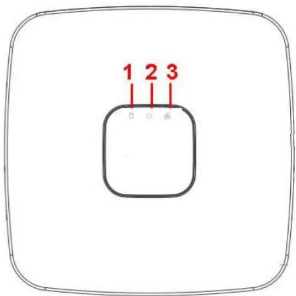
text_image
1 2 3Figure 2-1
Please refer to the following sheet for detailed information.
| SN | Name | Function |
| 1 | HDD status indicator light | The red light becomes on when HDD is abnormal. |
| 2 | Power indicator light | The red light becomes on when the power connection is OK. |
| 3 | Network status indicator light | The red light becomes on when the network connection is abnormal. |
2.1.2 NVR11H/11H-P/41H/41H-P/41H-8P Series
The front panel is shown as in Figure 2-2.

text_image
NET PWR HDD QDFigure 2-2
Please refer to the following sheet for detailed information.
| Icon | Name | Function |
| NET | Network status indicator light | The red light becomes on when the network connection is abnormal. |
| PWR | Power indicator light | The red light becomes on when the power connection is OK. |
| HDD | HDD status indicator light | The red light becomes on when HDD is abnormal. |
| IR | Remote control receiver | It is to receive signal from the remote control. |
2.1.3 NVR11HS Series
The front panel is shown as below. See Figure 2-3.

natural_image
Front view line drawing of a double air conditioner unit with ventilation grilles and control panel (no text or symbols)Figure 2-3
Please refer to the following sheet for detailed information.
| Icon | Name | Function |
 | Network status indicator light | The red light becomes on when the network connection is abnormal. |
| [23HK] | Power status indicator light | The red light becomes on when the power connection is OK. |
| [560X] | HDD status indicator light | The red light becomes on when the HDD is abnormal. |
 | USB port | Connect to USB mouse,USB devices and etc. |
2.1.4 NVR41-8P Series
The front panel is shown as below. See Figure 2-4.
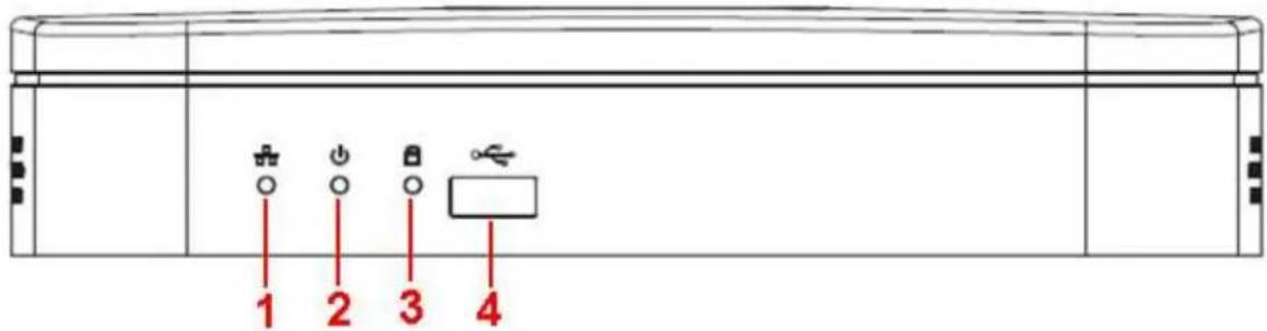
text_image
1 2 3 4Figure 2-4
Please refer to the following sheet for detailed information.
| SN | Name | Function |
| 1 | Network status indicator light | The red light becomes on when the network connection is abnormal. |
| 2 | Power indicator light | The red light becomes on when the power connection is OK. |
| 3 | HDD status indicator light | The red light becomes on when HDD is abnormal. |
| 4 | USB | USB port |
2.1.5 NVR42/42-P/42-8P/72/72-8P Series
The front panel is shown as below. See Figure 2-5.

text_image
1 2 3 4 5 6 7 8 9 10 11 12 13 14 15 16 17 18 19 20 21 22 23 24 25 26 27 28 29 30 31 Exo Fm Gnnt ExitFigure 2-5
Please refer to the following sheet for front panel button information.
| Name | Icon | Function |
| Power button | Power button, press this button for three seconds to boot up or shut down NVR. | |
| Shift | Shift | In textbox, click this button to switch between numeral, English(Small/Capitalized),donation and etc. |
| Up/1Down/4 | ▲、▼ | Activate current control, modify setup, and then move up and down. |
| Increase/decrease numeral. | ||
| Assistant function such as PTZ menu. | ||
| In text mode, input number 1/4 (English character G/H/I) | ||
| Left/2Right/3 | ◀ ▶ | Shift current activated control, |
| When playback, click these buttons to control playback bar.In text mode, input number 2(English character A/B/C)/3(English character D/E/F) | ||
| ESC | ESC | Go to previous menu, or cancel current operation. |
| When playback, click it to restore real-time monitor mode. | ||
| Enter | ENTER | Confirm current operation |
| Go to default button | ||
| Go to menu | ||
| Record | REC | Manually stop/start recording, working with direction keys or numeral keys to select the recording channel. |
| Slow play/8 | ▶ | Multiple slow play speeds or normal playback.In text mode, input number 8 (English character T/U/V). |
| Assistant | Fn | One-window monitor mode, click this button to display assistant function: PTZ control and image color. |
| Backspace function: in numeral control or text control, press it for 1.5seconds to delete the previous character before the cursor. | ||
| In motion detection setup, working with Fn and direction keys to realize setup. | ||
| In text mode, click it to switch between numeral, English character(small/capitalized) and etc. | ||
| Realize other special functions. | ||
| Fast play/7 | ▶ | Various fast speeds and normal playback.In text mode, input number 7 (English character P/Q/R/S). |
| Play previous/0 | |◀ | In playback mode, playback the previous videoIn text mode, input number 0. |
| Reverse/Pause/6 | ||◀ | In normal playback or pause mode, click this button to reverse playbackIn reverse playback, click this button to pause playback. |
| Play Next/9 | ▶| | In playback mode, playback the next videoIn menu setup, go to down ward of the dropdown list.In text mode, input number 9 (English character W/X/Y/Z) |
| Play/Pause /5 | ▶|| | In normal playback click this button to pause playbackIn pause mode, click this button to resume playback.In text mode, input number 5(English character J/K/L). |
| USB port | To connect USB storage device, USB mouse. | |
| Network abnormal indicator light | Net | Network error occurs or there is no network connection, the light becomes red to alert you. |
| HDD abnormal indicator light | HDD | HDD error occurs or HDD capacity is below specified threshold value, the light becomes red to alert you. |
| Record light | 1-16 | System is recording or not. It becomes on when system is recording. |
| IR Receiver | IR | It is to receive the signal from the remote control. |
2.1.6 NVR21HS-S2/21HS-P-S2/21HS-8P-S2/22-S2/22-P-S2/22-8P-S2 Series
The NVR21HS-S2/21HS-P-S2/21HS-8P-S2 series front panel is shown as below. See Figure 2-6.

text_image
HDD NET POWERFigure 2-6
The NVR22-S2/22-P-S2/22-8P-S2 series front panel is shown as in Figure 2-7.

text_image
DATA HLD NET POWER B D E F GFigure 2-7
Please refer to the following sheet for front panel button information.
| Icon | Name | Function |
| STATUS | Status indicator light | The blue light is on when the device is malfunction. NoteNVR21HS-S2 series product does not support STATUS indicator light. |
| HDD | HDD status indicator light | The blue light is on when the HDD is malfunction. |
| NET | Network status indicator light | The blue light is on when the network connection is abnormal. |
| POWER | Power status indicator light | The blue light is on when the power connection is OK. |
| USB port | Connect to peripheral USB storage device, mouse and etc. |
2.1.7 NVR42-16P/42N/42-4K/42-8P-4K/44-4K/48-4K/52-4KS2/52-8P-4KS2/52-16P-4KS2/54-4KS2/58-4KS2 Series
The NVR42-16P/42N/42-4K/42-8P-4K/52-4KS2/52-8P-4KS2/52-16P-4KS2 series front panel is shown as in Figure 2-8.

text_image
STATUS HDD NET POWER 0 0 0 0Figure 2-8
The NVR44-4K/54-4KS2/54-16P-4KS2 series front panel is shown as in Figure 2-9.

natural_image
Pure electrical circuit lines without any symbolsFigure 2-9
The NVR48-4K/58-4K/58-16P-4KS2 series front panel is shown as in Figure 2-10.
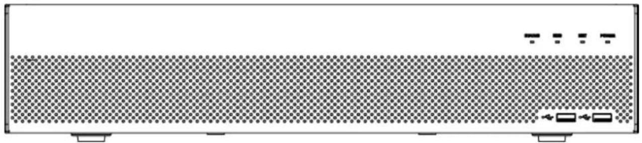
natural_image
Front view of a rectangular electronic device with a perforated panel and indicator lights (no text or symbols visible)Figure 2-10
Please refer to the following sheet for front panel button information.
| Icon | Name | Function |
| STATUS | Status indicator light | The blue light is on when the device is malfunction. |
| HDD | HDD status indicator light | The blue light is on when the HDD is malfunction. |
| NET | Network status indicator light | The blue light is on when the network connection is abnormal. |
| POWER | Power status indicator light | The blue light is on when the power connection is OK. |
| USB2.0 port | Connect to peripheral USB 2.0 storage device, mouse, burner and etc. |
2.1.8 NVR44/44-8P/44-16P/74/74-8P/74-16P Series
The front panel is shown as in Figure 2-11.

text_image
Control panel interface with buttons, display, and rotary knob labeled 'Enter'Figure 2-11
Please refer to the following sheet for front panel button information.
| Name | Icon | Function |
| Power button | [570Z] | Power button, press this button for three seconds to boot up or shut down NVR. |
| Shift | Shift | In textbox, click this button to switch between numeral, English(Small/Capitalized),donation and etc. |
| Up/1Down/4 | [SW33] | Activate current control, modify setup, and then move up and down. |
| Increase/decrease numeral. | ||
| Assistant function such as PTZ menu. | ||
| In text mode, input number 1/4 (English character G/H/I) | ||
| Left/2Right/3 | ◀ ▶ | Shift current activated control, |
| When playback, click these buttons to control playback bar.In text mode, input number 2(English character A/B/C)/3(English character D/E/F) | ||
| ESC | ESC | Go to previous menu, or cancel current operation. |
| When playback, click it to restore real-time monitor mode. | ||
| Enter | ENTER | Confirm current operation |
| Go to default button | ||
| Go to menu | ||
| Record | REC | Manually stop/start recording, working with direction keys or numeral keys to select the recording channel. |
| Slow play/8 | ▶ | Multiple slow play speeds or normal playback.In text mode, input number 8 (English character T/U/V). |
| Assistant | Fn | One-window monitor mode, click this button to display assistant function: PTZ control and image color. |
| Backspace function: in numeral control or text control, press it for 1.5seconds to delete the previous character before the cursor. | ||
| In motion detection setup, working with Fn and direction keys to realize setup. | ||
| In text mode, click it to switch between numeral, English character(small/capitalized) and etc. | ||
| Realize other special functions. | ||
| Fast play/7 | ▶ | Various fast speeds and normal playback.In text mode, input number 7 (English character P/Q/R/S). |
| Playprevious/0 | |◀ | In playback mode, playback the previous videoIn text mode, input number 0. |
| Reverse/Pause/6 | ||◀ | In normal playback or pause mode, click this button to reverse playbackIn reverse playback, click this button to pause playback. |
| Play Next/9 | ▶ | | In playback mode, playback the next videoIn menu setup, go to down ward of the dropdown list.In text mode, input number 9 (English character W/X/Y/Z) |
| Play/Pause /5 | ▶|| | In normal playback click this button to pause playback In pause mode, click this button to resume playback. In text mode, input number 5(English character J/K/L). |
| USB port | To connect USB storage device, USB mouse. | |
| Network abnormal indicator light | Net | Network error occurs or there is no network connection, the light becomes red to alert you. |
| HDD abnormal indicator light | HDD | HDD error occurs or HDD capacity is below specified threshold value, the light becomes red to alert you. |
| Record light | 1-16 | System is recording or not. It becomes on when system is recording. |
2.1.9 NVR48/48-16P/78/78-16P Series
The Front panel is shown as follows. See Figure 2-12.
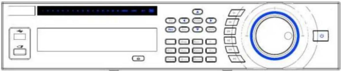
text_image
Control panel interface with buttons, display, and a rotary dial indicatorFigure 2-12
Please refer to the following sheet for front panel button information.
| Name | Icon | Function |
| Power button | Power button, press this button for three seconds to boot up or shut down NVR. | |
| Number button | 0-9 | Input Arabic numberSwitch channel |
| Input number more than 10 | -/-- | If you want to input a number more than 10, please click this button and then input. |
| Shift | ↑ | In textbox, click this button to switch between numeral, English(Small/Capitalized),donation and etc. |
| Enable or disable tour. | ||
| Up/Down | ▲、▼ | Activate current control, modify setup, and then move up and down. |
| Increase/decrease numeral. | ||
| Assistant function such as PTZ menu. | ||
| Left/Right | ◀ ▶ | Shift current activated control, and then move left and right. |
| When playback, click these buttons to control playback bar. | ||
| ESC | ESC | Go to previous menu, or cancel current operation. |
| When playback, click it to restore real-time monitor mode. | ||
| Enter | ENTER | Confirm current operation |
| Go to default button | ||
| Go to menu | ||
| Record | REC | Manually stop/start recording, working with direction keys or numeral keys to select the recording channel. |
| Slow play | ▶ | Multiple slow play speeds or normal playback. |
| Assistant | Fn | One-window monitor mode, click this button to display assistant function: PTZ control and image color. |
| Backspace function: in numeral control or text control, press it for 1.5seconds to delete the previous character before the cursor. | ||
| In motion detection setup, working with Fn and direction keys to realize setup. | ||
| In text mode, click it to switch between numeral, English character(small/capitalized) and etc. | ||
| In HDD management interface, you can click it to switch HDD record information and other information (Menu prompt) | ||
| Realize other special functions. | ||
| Fast play | ▶ | Various fast speeds and normal playback. |
| Play previous | |◀ | In playback mode, playback the previous video |
| Reverse/Pause | II ◀ | In normal playback or pause mode, click this button to reverse playbackIn reverse playback, click this button to pause playback. |
| Play Next | ▶| | In playback mode, playback the next videoIn menu setup, go to down ward of the dropdown list. |
| Play/Pause | ▶ II | In normal playback click this button to pause playbackIn pause mode, click this button to resume playback. |
| Window switch | Mult | Click it to switch one-window/multiple-window. |
| Shuttle(outer ring) | In real-time monitor mode it works as left/right direction key.Playback mode, counter clockwise to forward and clock wise to backward. | |
| Jog(inner dial) | Up/down direction key.Playback mode, turn the inner dial to realized frame by frame playback. (Only applies to some special versions.) | |
| USB port | To connect USB storage device, USB mouse. | |
| Remote control indicator light | ACT | Remote control indicator light |
| Status indicator light | Status | If there is Fn indicator light, current status indicator light is null. |
| Power indicator light | PWR | Power indicator light |
| Channel indicator light | 1-32 | For 4/8/16-channel series product.The corresponding channel light becomes on when system is recording.For 32/64-channel series product:When the light flashes slowly, it means the corresponding channel of 1-16 channel is recording now (Such as channel 1).When the light flashes fast, it means the corresponding channel of 17-32 channel is recording now (Such as channel 17)When the light becomes on, It means the corresponding 2 channels are recoding now (Such as channel 1 and channel 17). |
| IR Receiver | IR | It is to receive the signal from the remote control. |
2.1.10 NVR78-RH Series
The front panel is shown as below. See Figure 2-13.
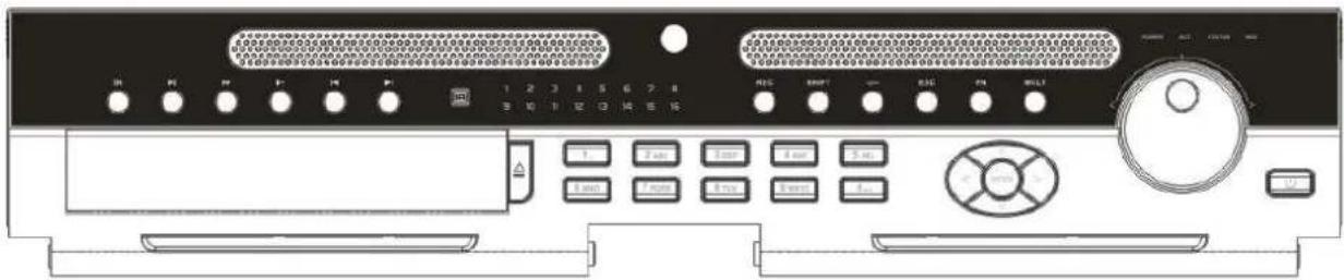
text_image
Front panel of a computer control interface with labeled buttons and portsFigure 2-13
Please refer to the following sheet for front panel button information.
| Name | Icon | Function |
| Power button | ➊ | Power button, press this button for three seconds to boot up or shut down NVR. |
| Number button | 0-9 | Input Arabic numberSwitch channel |
| Input number more than 10 | -/-- | If you want to input a number more than 10, please click this button and then input. |
| Shift | ↑ | In textbox, click this button to switch between numeral, English(Small/Capitalized),donation and etc. |
| Enable or disable tour. | ||
| Up/Down | ▲、▼ | Activate current control, modify setup, and then move up and down. |
| Increase/decrease numeral. | ||
| Assistant function such as PTZ menu. | ||
| Left/Right | ◀ ▶ | Shift current activated control, and then move left and right. |
| When playback, click these buttons to control playback bar. | ||
| ESC | ESC | Go to previous menu, or cancel current operation. |
| When playback, click it to restore real-time monitor mode. | ||
| Enter | ENTER | Confirm current operation |
| Go to default button | ||
| Go to menu | ||
| Record | REC | Manually stop/start recording, working with direction keys or numeral keys to select the recording channel. |
| Slow play | ▸ | Multiple slow play speeds or normal playback. |
| Assistant | Fn | One-window monitor mode, click this button to display assistant function: PTZ control and image color. |
| Backspace function: in numeral control or text control, press it for 1.5 seconds to delete the previous character before the cursor. | ||
| In motion detection setup, working with Fn and direction keys to realize setup. | ||
| In text mode, click it to switch between numeral, English character(small/capitalized) and etc. | ||
| In HDD management interface, you can click it to switch HDD record information and other information (Menu prompt) | ||
| Realize other special functions. | ||
| Fast play | ▸ | Various fast speeds and normal playback. |
| Play previous | |◀ | In playback mode, playback the previous video |
| Reverse/Pause | ||◀ | In normal playback or pause mode, click this button to reverse playbackIn reverse playback, click this button to pause playback. |
| Play Next | ▶| | In playback mode, playback the next videoIn menu setup, go to down ward of the dropdown list. |
| Play/Pause | ▶|| | In normal playback click this button to pause playbackIn pause mode, click this button to resume playback. |
| Window switch | Mult | Click it to switch one-window/multiple-window. |
| Shuttle(outer ring) | In real-time monitor mode it works as left/right direction key.Playback mode, counter clockwise to forward and clock wise to backward. | |
| Jog(inner dial) | Up/down direction key.Playback mode, turn the inner dial to realized frame by frame playback. (Only applies to some special versions.) | |
| USB port | To connect USB storage device, USB mouse. | |
| Remote control receiver | IR | It is to receive signal from the remote control. |
| Remote control indicator light | ACT | Remote control indicator light |
| Status indicator light | Status | The light is on if device operates properly. |
| Power indicator light | POWER | Power indicator light |
| Record light | 1-16 | It becomes on when system is recording. |
| HDD abnormal status indicator light | HDD | It becomes on when there is no HDD, HDD error occurs, or HDD is full. |
2.1.11 NVR70/70-R Series
The front panel is shown as in Figure 2-14.
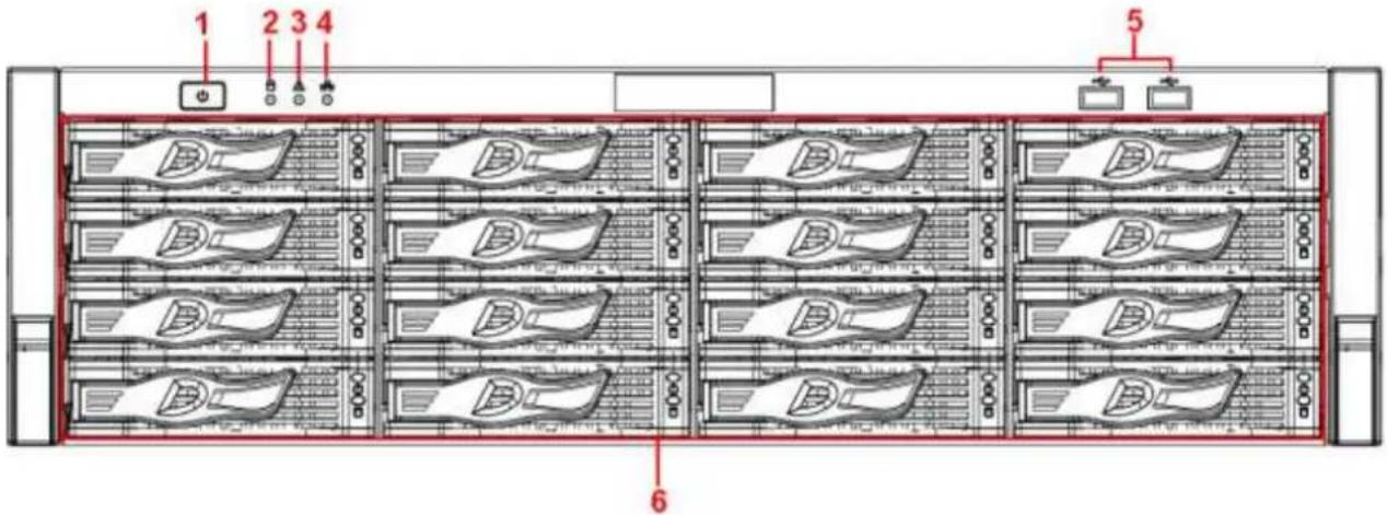
text_image
1 2 3 4 5 6Figure 2-14
Please refer to the following sheet for front panel button information.
| SN | Name | Icon | Function |
| 1 | Power button | Press it once to turn on the device.Press it for a long time to turn off the device (Usually we do not recommend).Press power button for a long time or pull out the power cable may result in device auto restart. | |
| 2 | System HDD Indicator light | The blue light flashes when system is reading or writing the system HDD.In the system HDD, there are device important configuration file, factory default configuration file, device initial boot up data. | |
| 3 | Alarm indicator light | The alarm indicator light becomes on once an alarm occurred. It becomes on via the software detection.The alarm includes local alarm, no disk and etc. | |
| 4 | Network indicator light | The network indicator light is blue and it flashes when you connect the device to the network. | |
| 5 | USB2.0 port | Connect to USB2.0 storage device, mouse, USB burner and etc. | |
| 6 | 16 HDD slot | - | / |
After you remove the front panel, you can see there are 16 HDDs. From the left to the right and from the top to the bottom, it ranges from 1\~4, 5\~8, 6\~12, 13\~16. See Figure 2-15.
You can see there are two indicator lights on the HDD bracket.
● The power indicator light is at the top. The light is yellow after you connected the device to the power.
- The read-write indicator light is at the bottom. The blue light flashes when system is reading or writing the data.
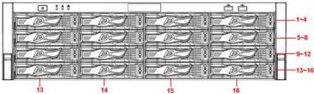
text_image
1~4 5~8 9~12 13~16 13 14 15 16Figure 2-15
2.1.12 NVR42V-8P Series
The front panel is shown as below. See Figure 2-16
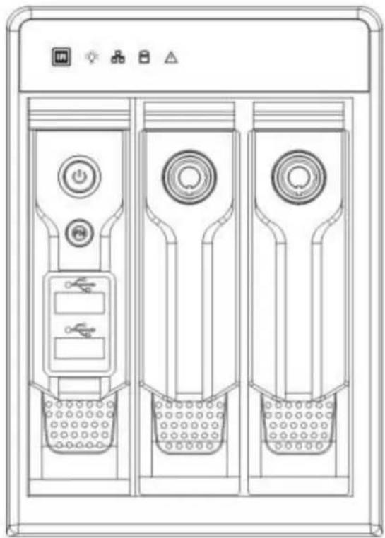
natural_image
Technical line drawing of a three-panel air conditioner unit with control buttons and indicator lights (no text or symbols)Figure 2-16
Please refer to the following sheet for front panel button information.
| Name | Icon | Function |
| Power button | 💡 | Power button, press this button for three seconds to boot up or shut down NVR. |
| Assistant | Fn | One-window monitor mode, click this button to display assistant function: PTZ control and image color.Backspace function: in numeral control or text control, press it for 1.5 seconds to delete the previous character before the cursor.In motion detection setup, working with Fn and direction keys to realize setup.In text mode, click it to switch between numeral, Englishcharacter (small/capitalized) and etc.● In HDD management interface, you can click it to switch HDD record information and other information (Menu prompt)● Realize other special functions. |
| USB2.0 port |  | To connect USB2.0 storage device, USB2.0 mouse, burner and etc. |
| IR receive window |  | It is to receive the IR signal from the remote control. |
| Power indicator light | [4T0Z] | Power indicator light. |
| HDD abnormal indicator light |  | HDD error occurs or HDD capacity is below specified threshold value, the light becomes red to alert you. |
| Network abnormal indicator light |  | Network error occurs or there is no network connection, the light becomes red to alert you. |
| Alarm indicator light | △ | The light becomes on when an alarm occurred. |
2.2 Rear Panel
2.2.1 NVR100/100-P Series
The NVR100 rear panel is shown as below. See Figure 2-17.

text_image
Diagram of a front panel with labeled ports and connectors including USB port, VGA, and DC 5V indicatorFigure 2-17
The NVR100-P rear panel is shown as below. See Figure 2-18.

text_image
DC-68V PoE PDK7B H201U VGAFigure 2-18
Please refer to the following sheet for detailed information.
| Port Name | Connection | Function |
| USB2.0 port | USB2.0 port. Connect to mouse, USB storage device, USB burner and etc. | |
| Network port | 10M/100Mbps self-adaptive Ethernet port. Connect to the network cable. | |
| HDMI | High Definition Media Interface | High definition audio and video signal output port. It transmits uncompressed high definition video and multiple-channel data to the HDMI port of the display device. HDMI version is 1.4. |
| VGA | VGA video output port | VGA video output port. Output analog video signal. It can connect to the monitor to view analog video. |
| DC12V | Power input port | Power socket.● For NVR100 series, input DC 5V/2A.● For NVR100-P series, input DC 48V/1.25A. |
| PoE PORT | PoE port | Built-in switch. Support PoE function. For PoE series product, you can use this port to provide power to the network camera. |
2.2.2 NVR11/11-P Series
The NVR11 rear panel is shown as below. See Figure 2-19.
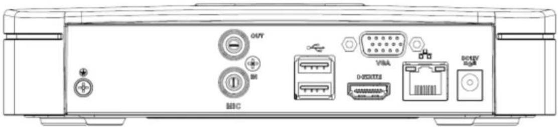
text_image
OAFY VBA D-DCSKEE BCTEV MBCFigure 2-19
The NVR11-P rear panel is shown as below. See Figure 2-20.
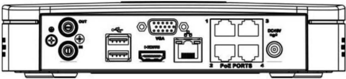
text_image
OUT VGA DC45V 1 2 PoE PORTS 3 DC45V sg²Figure 2-20
Please refer to the following sheet for detailed information.
| Port Name | Connection | Function |
| USB2.0 port | USB2.0 port. Connect to mouse, USB storage device, USB burner and etc. | |
| Network port | 10M/100Mbps self-adaptive Ethernet port. Connect to the network cable. | |
| HDMI | High Definition Media Interface | High definition audio and video signal output port. It transmits uncompressed high definition video and multiple-channel data to the HDMI port of the display device. HDMI version is 1.4. |
| VGA | VGA video output port | VGA video output port. Output analog video signal. It can connect to the monitor to view analog video. |
| GND | Ground end | |
| DC12V-G | Power input port | Power socket.● For NVR11 series, input DC 12V/2A.● For NVR11-P series, input DC 48V/1.25A. |
| MIC IN | Audio input port | Bidirectional talk input port. It is to receive the analog audio signal output from the devices such as microphone, pickup. |
| MIC OUT | Audio output port | Audio output port. It is to output the analog audio signal to the devices such as the sound box.● Bidirectional talk output.● Audio output on 1-window video monitor.● Audio output on 1-window video playback. |
| PoE PORT | PoE port | Built-in switch. Support PoE function. For PoE series product, you can use this port to provide power to the network camera. |
2.2.3 NVR41/41-P/41-8P/41-W Series
The NVR41 rear panel is shown as below. See Figure 2-21.
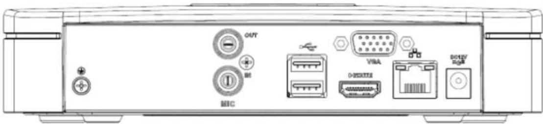
text_image
OUT MHC VBA DOSKUSSS BCLTVFigure 2-21
The NVR41-P rear panel is shown as below. See Figure 2-22.
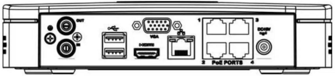
text_image
OUT VGA DDR/RSB 1 2 PoE PORTS 3 DOASM port 4Figure 2-22
The NVR41-8P rear panel is shown as below. See Figure 2-23.

text_image
MDC USB USB PeE PORT8 1307 1468 DCB25 +/-Figure 2-23
The NVR41-W rear panel is shown as below. See Figure 2-24.
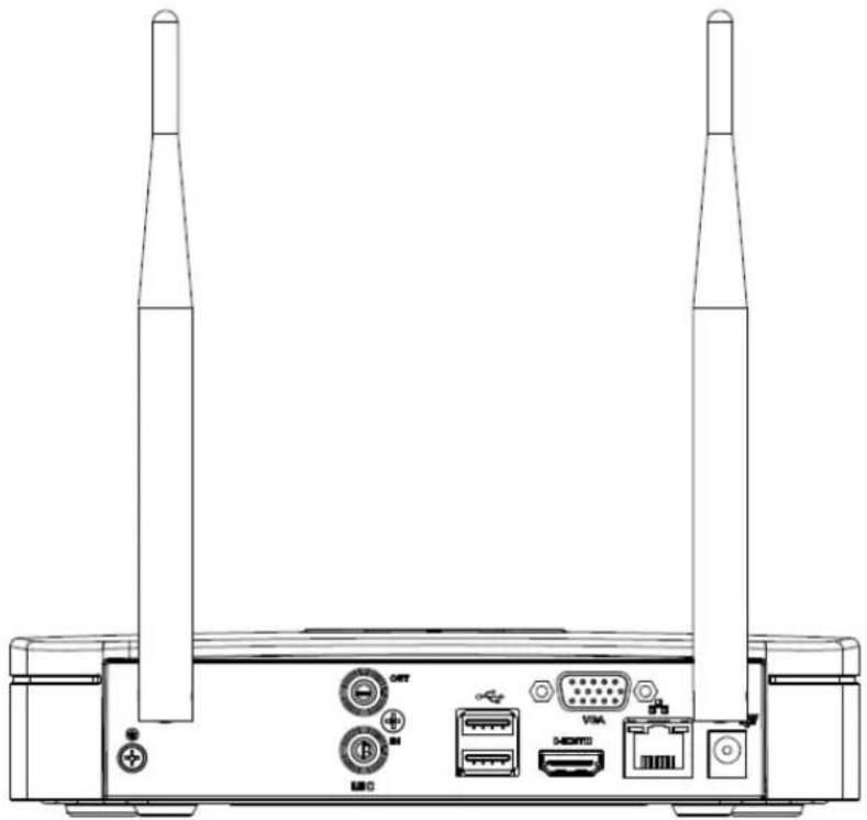
natural_image
Technical line drawing of a wireless router with two towers and ports (no text or symbols)Figure 2-24
Please refer to the following sheet for detailed information.
| Port Name | Connection | Function |
| USB2.0 port | USB2.0 port. Connect to mouse, USB storage device, USB burner and etc. | |
| Network port | 10M/100Mbps self-adaptive Ethernet port. Connect to the network cable. | |
| HDMI | High Definition Media Interface | High definition audio and video signal output port. It transmits uncompressed high definition video and multiple-channel data to the HDMI port of the display device. HDMI version is 1.4. |
| VGA | VGA video output port | VGA video output port. Output analog video signal. It can connect to the monitor to view analog video. |
| 12 | GND | Ground end |
| DC 12V DC 48V 12 / 12 | Power input port | Power socket.● For NVR41 series, input DC 12V/2A.● For NVR41-P series, input DC 48V/1.5A.● For NVR41-8P series, input DC 48V/2A. |
| MIC IN | Audio input port | Bidirectional talk input port. It is to receive the analog audio signal output from the devices such as microphone, pickup. |
| MIC OUT | Audio output port | Audio output port. It is to output the analog audio signal to the devices such as the sound box.● Bidirectional talk output.● Audio output on 1-window video monitor.● Audio output on 1-window video playback. |
| PoE PORT | PoE port | Built-in switch. Support PoE function. For PoE series product, you can use this port to provide power to the network camera. |
| Wireless AP | Support wireless hotspot function. Use WIFI to connect to the network camera when there is a hotspot.For 41-W series only. |
2.2.4 NVR21-S2/21-P-S2/21-8P-S2 Series
The NVR21-S2 is shown as in Figure 2-25.
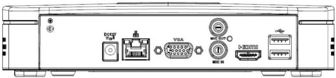
text_image
DC12V =0.1 VGA MIC OUT MIC IN HDMIFigure 2-25
The NVR21-P-S2 is shown as in Figure 2-26.
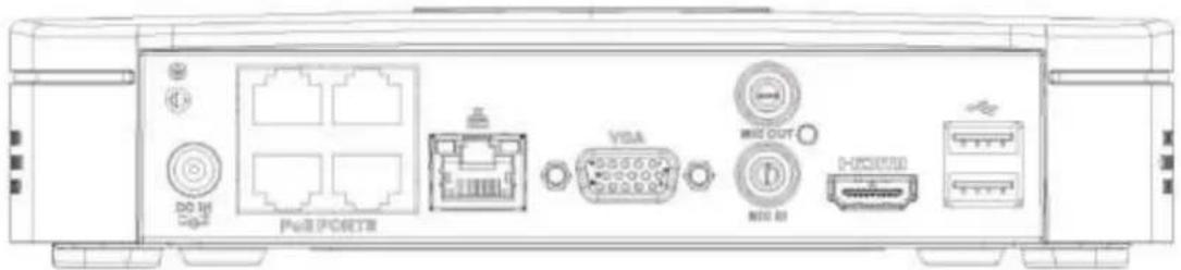
text_image
DO HA PoE PORTB VGA MIO OUT MIO BI MIOUSBFigure 2-26
The NVR21-8P-S2 is shown as in Figure 2-27.
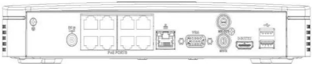
text_image
PAA PORTB VMA MECUT EthernetFigure 2-27
Please refer to the following sheet for detailed information.
| Port Name | Connection | Function |
 | Power input port | Power socketFor NVR21-S2, input DC 12V/2A.For NVR21-P-S2, input DC 48V/1.25A.For NVR21-8P-S2, input DC 48V/2A. |
 | Network port | 10M/100Mbps self-adaptive Ethernet port. Connect to the network cable. |
 | USB port | USB port. Connect to mouse, USB storage device and etc. |
 | High Definition Media Interface | High definition audio and video signal output port. It transmits uncompressed high definition video and multiple-channel data to the HDMI port of the display device. HDMI version is 1.4. |
 VGA VGA | VGA video output port | VGA video output port. Output analog video signal. It can connect to the monitor to view analog video. |
 N N | Audio input port | Bidirectional talk input port. It is to receive the analog audio signal output from the devices such as microphone, pickup. |
 OUT OUT | Audio output port | Audio output port. It is to output the analog audio signal to the devices such as the sound box.Bidirectional talk output.Audio output on 1-window video monitor.Audio output on 1-window video playback. |
 | GND | Ground end |
| PoE PORTS | PoE port | Built-in switch. Support PoE function.For PoE series product, you can use this port to provide power to the network camera. |
2.2.5 NVR11H/11H-P/41H/41H-P/41H-8P Series
The NVR11H/41H rear panel is shown as in Figure 2-28.

text_image
Diagram of a device rear panel with labeled ports and icons including power, ventilation, and control unitsFigure 2-28
The NVR11H-P/41H-P rear panel is shown as in Figure 2-29.

text_image
Technical diagram of a network device rear panel with labeled ports and connectorsFigure 2-29
The NVR41H-8P rear panel is shown as in Figure 2-30.

text_image
Technical diagram of a device rear panel with labeled ports, connectors, and control panelFigure 2-30
Please refer to the following sheet for detailed information.
| Port Name | Connection | Function |
| USB2.0 port | USB2.0 port. Connect to mouse, USB storage device, USB burner and etc. | |
| Network port | 10M/100Mbps self-adaptive Ethernet port. Connect to the network cable. | |
| HDMI | High Definition Media Interface | High definition audio and video signal output port. It transmits uncompressed high definition video and multiple-channel data to the HDMI port of the display device. HDMI version is 1.4. |
| VGA | VGA video output port | VGA video output port. Output analog video signal. It can connect to the monitor to view analog video. |
| 12 | GND | Ground end |
| DC 12V 12 DC 48V / 12 | Power input port | Power socket.For NVR41 series, input DC 12V/2A.For NVR41H-P series, input DC 48V/1.5A.For NVR11H-P series, input DC 48V/1.25A.For NVR41H-8P series, input DC 48V/2A. |
| MIC IN | Audio input port | Bidirectional talk input port. It is to receive the analog audio signal output from the devices such as microphone, pickup. |
| MIC OUT | Audio output port | Audio output port. It is to output the analog audio signal to the devices such as the sound box.Bidirectional talk output.Audio output on 1-window video monitor.Audio output on 1-window video playback. |
| PoE PORT | PoE port | Built-in switch. Support PoE function.For PoE series product, you can use this port to provide power to the network camera. |
2.2.6 NVR11HS Series
The series rear panel is shown as below. See Figure 2-31.

natural_image
Back panel diagram showing external components including ports, connectors, and a USB port (no text or labels)Figure 2-31
Please refer to the following sheet for detailed information.
| Icon | Name | Function |
| DC12V | Power input socket. | Power socket. Input DC12V/1.5A. |
| Network port | 10M/100Mbps self-adaptive Ethernet port. Connect to the network cable. | |
| USB2.0 port | USB2.0 port. Connect to mouse, USB storage device, and etc. | |
| HDMI | High Definition Media Interface | High definition audio and video signal output port. It transmits uncompressed high definition video and multiple-channel data to the HDMI port of the display device. HDMI version is 1.4. |
| VGA | VGA video output port | VGA video output port. Output analog video signal. It can connect to the monitor to view analog video. |
| 12 | GND | Ground end |
2.2.7 NVR21HS-S2/21HS-P-S2/21HS-8P-S2 Series
The NVR21HS-S2 series rear panel is shown as below. See Figure 2-32.

text_image
MHC OUT VGA MHC MI DCKOUTFigure 2-32
The NVR21HS-P-S2 series rear panel is shown as below. See Figure 2-33.

text_image
PoE PORTS DO EX Up8 VISA MIC OUT MIC IN DO EXTRI MACFigure 2-33
The NVR21HS-8P-S2 series rear panel is shown as below. See Figure 2-34.

text_image
PoE PORTS 1 2 3 4 5 6 7 DO IN VGA BIG OUT DIG IN I-30000 T1111Figure 2-34
Please refer to the following sheet for detailed information.
| Port Name | Connection | Function |
| DC12V | Power input port | Power socket.For NVR21HS-S2, input DC 12V/2A.For NVR21HS-P-S2, input DC 48V/1.25A.For NVR21HS-8P-S2, input DC 48V/2A. |
| Network port | 10M/100Mbps self-adaptive Ethernet port. Connect to the network cable. | |
| USB port | USB port. Connect to mouse, USB storage device and etc. | |
| HDMI | High Definition Media Interface | High definition audio and video signal output port. It transmits uncompressed high definition video and multiple-channel data to the HDMI port of the display device. HDMI version is 1.4. |
| VGA | VGA video output port | VGA video output port. Output analog video signal. It can connect to the monitor to view analog video. |
| MIC IN | Audio input port | Bidirectional talk input port. It is to receive the analog audio signal output from the devices such as microphone, pickup. |
| MIC OUT | Audio output port | Audio output port. It is to output the analog audio signal to the devices such as the sound box.Bidirectional talk output.Audio output on 1-window video monitor.Audio output on 1-window video playback. |
| ⊥ | GND | Ground end |
| PoE PORTS | PoE port | Built-in switch. Support PoE function.For PoE series product, you can use this port to provide power to the network camera. |
2.2.8 NVR22-S2/22-P-S2/22-8P-S2 Series
The NVR22-S2 series rear panel is shown as below. See Figure 2-35.

text_image
USB OFF GPIO VGA MHCFigure 2-35
The NVR22-P-S2 series rear panel is shown as below. See Figure 2-36.

text_image
PaaS PORT9 ON OFF VGA MICFigure 2-36
The NVR22-8P-S2 series rear panel is shown as below. See Figure 2-37.

text_image
PoE PORTS ON OFF VGA MIC +G+Figure 2-37
Please refer to the following sheet for detailed information.
| Port Name | Connection | Function |
| DC 12V | Power input port | Power socket.For NVR22-S2, input DC 12V/4A.For NVR22-P-S2, input DC 48V/1.5A.For NVR22-8P-S2, input DC 53V 120W. |
| Network port | 10M/100Mbps self-adaptive Ethernet port. Connect to the network cable. | |
| USB port | USB port. Connect to mouse, USB storage device and etc. | |
| HDMI | High Definition Media Interface | High definition audio and video signal output port. It transmits uncompressed high definition video and multiple-channel data to the HDMI port of the display device. HDMI version is 1.4. |
| VGA | VGA video output port | VGA video output port. Output analog video signal. It can connect to the monitor to view analog video. |
| MIC IN | Audio input port | Bidirectional talk input port. It is to receive the analog audio signal output from the devices such as microphone, pickup. |
| MIC OUT | Audio output port | Audio output port. It is to output the analog audio signal to the devices such as the sound box.Bidirectional talk output.Audio output on 1-window video monitor.Audio output on 1-window video playback. |
| GND | Ground end | |
| PoE PORTS | PoE port | Built-in switch. Support PoE function.For PoE series product, you can use this port to provide power to the network camera. |
2.2.9 NVR42/42N/42-P/42-8P/42-16P Series
The NVR42 series rear panel is shown as below. See Figure 2-38.

natural_image
Back panel of a network equipment unit showing ports, connectors, and indicators (no readable text or symbols)Figure 2-38
The NVR42N series rear panel is shown as below. See Figure 2-39.

text_image
VGA RS222 HDMI SP RE12V ON OFFFigure 2-39
The NVR42-P series rear panel is shown as below. See Figure 2-40.

text_image
DCAM VGA MS232 HDMI USB M120 I/O OFFFigure 2-40
The NVR42-8P series rear panel is shown as below. See Figure 2-41.

text_image
Diagram of a device rear panel showing labeled ports and connectors including GPIO, VGA, RS232, and HDMI interface.Figure 2-41
The NVR42-16P series rear panel is shown as below. See Figure 2-42.

text_image
PANOSYS V2A H0173 H0173 H0173 H0173 H0173 H0173 H0173 H0173 H0173 H0173 H0173 H0173 H0173 H0173 H0173 H0173 H0173 H02C-Figure 2-42
Please refer to the following sheet for detailed information.
| Name | Function | |
 | Power switch | Power on/off button. |
 | ||
 | Power input port | Input DC 12V/5A.For NVR42 series product only. |
 | Switch power port. Input DC 48//1.04A.For NVR42-P series product only. | |
 | Input AC 100~240V.For NVR42-8P/42-16P series product only. | |
| MIC IN | Audio input port | Bidirectional talk input port. It is to receive the analog audio signal output from the devices such as microphone, pickup. |
| MIC OUT | Audio output port | Audio output port. It is to output the analog audio signal to the devices such as the sound box.Bidirectional talk output.Audio output on 1-window video monitor.Audio output on 1-window video playback. |
| 1~4 | Alarm input port1~4 | There are two types; NO (normal open)/NC (normal close).When your alarm input device is using external power, please make sure the device and the NVR have the same ground. |
| 12 | GND | Alarm input ground port. |
| N1, N2 | Alarm output port1~2 | 2 groups of alarm output ports. (Group 1: port NO1~C1, Group 2: port NO2~C2). Output alarm signal to the alarm device. Please make sure there is power to the external alarm device.NO: Normal open alarm output port.C: Alarm output public end. |
| C1, C2 | ||
| A | RS-485 communication port | RS485_A port. It is the cable A. You can connect to the control devices such as speed dome PTZ. |
| B | RS485_B. It is the cable B. You can connect to the control devices such as speed dome PTZ. | |
| Network port | 10M/100M/1000Mbps self-adaptive Ethernet port. Connect to the network cable. | |
| USB2.0 port | USB2.0 port. Connect to mouse, USB storage device, USB burner and etc. | |
| RS-232 | RS-232 debug COM. | It is for general COM debug to configure IP address or transfer transparent COM data. |
| HDMI | High Definition Media Interface | High definition audio and video signal output port. It transmits uncompressed high definition video and multiple-channel data to the HDMI port of the display device. HDMI version is 1.4. |
| VGA | VGA video output port | VGA video output port. Output analog video signal. It can connect to the monitor to view analog video. |
| PoE PORTS | / | Built-in Switch. Support PoE.The 4 PoE series product supports total 48V 50W.The 8 PoE series product supports total 48V 120W.The 16 PoE series product supports total 120W. One PoE port max supports 15W. |
2.2.10 NVR42-4K/52-4KS2/52-8P-4KS2/52-16P-4KS2 Series
The NVR42-4K/52-4KS2 series rear panel is shown as below. See Figure 2-43.

text_image
HDMI SPC VGA RS232 DC OCEU ON OFFFigure 2-43
The NVR52-8P-4KS2 series rear panel is shown as below. See Figure 2-44.

text_image
Back panel diagram of a network equipment module showing ports, connectors, and interfaces like VGA, RS232, and HDMIFigure 2-44
The NVR52-16P-4KS2 series rear panel is shown as below. See Figure 2-45.

text_image
PORTS 1 3 5 7 9 11 13 15 2 4 6 8 10 12 14 16 VGA HOS DOS MCCFigure 2-45
Please refer to the following sheet for detailed information.
| Icon | Port Name | Function |
| Network port | 10M/100M/1000Mbps self-adaptive Ethernet port. Connect to the network cable. | |
| HDMI | High Definition Media Interface | High definition audio and video signal output port. It transmits uncompressed high definition video and multiple-channel data to the HDMI port of the display device. HDMI version is 1.4. |
| SS← | USB3.0 port | USB3.0 port. Connect to mouse, USB storage device, USB burner and etc. |
| RS-232 | RS-232 debug COM. | It is for general COM debug to configure IP address or transfer transparent COM data. |
| VGA | VGA video output port | VGA video output port. Output analog video signal. It can connect to the monitor to view analog video. |
| MIC IN | Audio input port | Bidirectional talk input port. It is to receive the analog audio signal output from the devices such as microphone, pickup. |
| MIC OUT | Audio output port | Audio output port. It is to output the analog audio signal to the devices such as the sound box.Bidirectional talk output.Audio output on 1-window video monitor.Audio output on 1-window video playback. |
| 1~8 | Alarm input port1~8 | There are two groups. The first group is from port 1 to port 4; the second group is from port 5 to port 8. They are to receive the signal from the external alarm source. There are two types; NO (normal open)/NC (normal close).When your alarm input device is using external power, please make sure the device and the NVR have the same ground. |
| 12 | GND | Alarm input ground port. |
| NO1~NO3 | Alarm output port1~3 | 3 groups of alarm output ports. (Group 1: port NO1 ~ C1, Group 2: port NO2 ~ C2, Group 3: po NO3~C3)). Output alarm signal to the alarm device. Please make sure there is power to the external alarm device.NO: Normal open alarm output port.C: Alarm output public end. |
| C1~C3 | ||
| A | RS-485communication port | RS485_A port. It is the cable A. You can connect to the control devices such as speed dome PTZ. |
| B | RS485_B.It is the cable B. You can connect to the control devices such as speed dome PTZ. | |
| DC 12V 12 | Power input port | Input DC 12V/4A. |
| Power switch | / | Power on/off button. |
| PoE PORTS | / | Built-in Switch. Support PoE.The 8 PoE series product supports total 130W.The 16 PoE series product supports total 130W. |
2.2.11 NVR42-8P-4K Series
The NVR42-8P-4K series rear panel is shown as below. See Figure 2-46.

text_image
Pcs2 PORTS HOM 50°C VGA RJ222 RJFigure 2-46
Please refer to the following sheet for detailed information.
| Icon | Port Name | Function |
| Power socket | / | Input AC 220V. |
| Power switch | / | Power on/off button. |
| PoE PORTS | PoE port | Built-in Switch, support PoE. The PoE PORTS can provide power to the network camera.The 8 PoE ports series product can support 48V 120W. |
| Network port | 10M/100M/1000Mbps self-adaptive Ethernet port.Connect to the network cable. | |
| HDMI | High Definition Media Interface | High definition audio and video signal output port. It transmits uncompressed high definition video and multiple-channel data to the HDMI port of the display device. HDMI version is 1.4. |
| SS←→ | USB3.0 port | USB3.0 port. Connect to mouse, USB storage device, USB burner and etc. |
| RS-232 | RS-232 debug COM. | It is for general COM debug to configure IP address or transfer transparent COM data. |
| VGA | VGA video output port | VGA video output port. Output analog video signal. It can connect to the monitor to view analog video. |
| MIC IN | Audio input port | Bidirectional talk input port. It is to receive the analog audio signal output from the devices such as microphone, pickup. |
| MIC OUT | Audio output port | Audio output port. It is to output the analog audio signal to the devices such as the sound box.Bidirectional talk output.Audio output on 1-window video monitor.Audio output on 1-window video playback. |
| 1~4 | Alarm input port 1~4 | They are to receive the signal from the external alarm source. There are two types; NO (normal open)/NC (normal close).When your alarm input device is using external power, please make sure the device and the NVR have the same ground. |
| ± | GND | Alarm input ground port. |
| N1,N2 | Alarm output port 1~2 | 2 groups of alarm output ports. (group 1: port NO1~C1, group 2: port NO2~C2). Output alarm signal to the alarm device. Please make sure there is power to the external alarm device.NO: Normal open alarm output port.C: Alarm output public end. |
| C1~C2 | ||
| A | RS-485 communication port | RS485_A port. It is the cable A. You can connect to the control devices such as speed dome PTZ. |
| B | RS485_B.It is the cable B. You can connect to the control devices such as speed dome PTZ. |
2.2.12 NVR44/44-8P/44-16P Series
The NVR44 series rear panel is shown as below. See Figure 2-47.

text_image
Technical diagram of an electronic device rear panel with labeled ports and connectorsFigure 2-47
The NVR44-8P series rear panel is shown as below. See Figure 2-48.

text_image
Technical diagram of an electronic device rear panel with labeled ports, connectors, and internal componentsFigure 2-48
The NVR44-16P series rear panel is shown as below. See Figure 2-49.

text_image
Bus POINTS 1 2 3 4 5 6 7 8 9 10 11 12 13 14 15 VGA RS232Figure 2-49
Please refer to the following sheet for detailed information.
| Name | Function | |
| Power switch | / | Power on-off button |
| Power input port | / | Input AC 100~240V. |
| MIC IN | Audio input port | Bidirectional talk input port. It is to receive the analog audio signal output from the devices such as microphone, pickup. |
| MIC OUT | Audio output port | Audio output port. It is to output the analog audio signal to the devices such as the sound box.Bidirectional talk output.Audio output on 1-window video monitor.Audio output on 1-window video playback. |
| VIEDEO OUT | Video output port | CVBS output |
| 1~16 | Alarm input port1~16 | There are four groups. The first group is from port 1 to port 4, the second group is from port 5 to port 8, the third group is from 9 to 12, and the fourth group is from 13 to 16. They are to receive the signal from the external alarm source. There are two types; NO (normal open)/NC (normal close).When your alarm input device is using external power, please make sure the device and the NVR have the same ground. |
| 12 | Video output port | CVBS output |
| NO1~NO5 | Alarm output port1~5 | 5 groups of alarm output ports. (Group 1: port NO1~C1, Group 2: port NO2~C2, Group 3: port NO3~C3, Group 4: port NO4~C4, Group 5: port NO5, C5, NC5). Output alarm signal to the alarm device. Please make sure there is power to the external alarm device.NO: Normal open alarm output port.C: Alarm output public end.NC: Normal close alarm output port. |
| C1~C5 | ||
| NC5 | ||
| A | RS-485communicationport | RS485_A port. It is the cable A. You can connect to the control devices such as speed dome PTZ. |
| B | RS485_B.It is the cable B. You can connect to the control devices such as speed dome PTZ. | |
| CTRL 12V | / | Controller 12V power output. It is to control the on-off alarm relay output. It can be used to control the device alarm output. At the same time, it can also be used as the power input source of some devices such as the alarm detector. |
| +12V | / | +12V power output port. It can provide the power to some peripheral devices such as the camera or the alarm device. Please note the supplying power shall be below 1A. |
| Network port | 10M/100M/1000Mbps self-adaptive Ethernet port. Connect to the network cable. | |
| eSATA | eSATA portUSB2.0 port | External SATA port. It can connect to the device of the SATA port. Please jump the HDD when there is peripheral connected HDD.USB2.0 port. Connect to mouse, USB storage device, USB burner and etc. |
| RS-232 | RS232 debug COM. | It is for general COM debug to configure IP address or transfer transparent COM data. |
| HDMI | High Definition Media Interface | High definition audio and video signal output port. It transmits uncompressed high definition video and multiple-channel data to the HDMI port of the display device. HDMI version is 1.3 |
| VGA | VGA video output port | VGA video output port. Output analog video signal. It can connect to the monitor to view analog video. |
| PoE PORTS | 8 PoE ports | Built-in Switch. Support PoE.The 8 PoE ports series products supports total 48V 120W power. One PoE port max supports 15W. |
| PoE PORTS | 16 PoE ports | Built-in Switch. Support PoE. The 16 PoE ports series products supports total 150W power. One PoE port max supports 15W. |
2.2.13 NVR44-4K/48-4K/54-4KS2/58-4KS2/54-16P-4KS2/58-16P-4KS2 Series
The NVR44-4K/NVR48-4K/ NVR54-4KS2/NVR58-4KS2 series rear panel is shown as below. See Figure 2-50.

text_image
Technical diagram of a rack-mounted server or network device with labeled ports and connectorsFigure 2-50
The NVR54-16P-4KS2/NVR58-16P-4KS2 series rear panel is shown as below. See Figure 2-51.

text_image
Out PORTS 1 2 3 4 5 6 7 8 9 10 11 12 13 14 15 2 3 4 5 6 7 8 9 10 11 12 13 14 MS222 VGAFigure 2-51
Please refer to the following sheet for detailed information.
| Name | Function | |
 | Power switch | Power on-off button |
| [wzcy] | Power input port | Input AC 100~240V. |
| Network port | 10M/100M/1000Mbps self-adaptive Ethernet port. Connect to the network cable. | |
| eSATA | eSATA port | External SATA port. It can connect to the device of the SATA port. Please jump the HDD when there is peripheral connected HDD. |
| SS← | USB3.0 port | USB3.0 port. Connect to mouse, USB storage device, USB burner and etc. |
| HDMI | High Definition Media Interface | High definition audio and video signal output port. It transmits uncompressed high definition video and multiple-channel data to the HDMI port of the display device. HDMI version is 1.4b. |
| MIC IN | Audio input port | Bidirectional talk input port. It is to receive the analog audio signal output from the devices such as microphone, pickup. |
| MIC OUT | Audio output port | Audio output port. It is to output the analog audio signal to the devices such as the sound box.Bidirectional talk output.Audio output on 1-window video monitor.Audio output on 1-window video playback. |
| 1~16 | Alarm input port 1~16 | There are four groups. The first group is from port 1 to port 4, the second group is from port 5 to port 8, the third group is from 9 to 12, and the fourth group is from 13 to 16. They are to receive the signal from the external alarm source. There are two types; NO (normal open)/NC (normal close).When your alarm input device is using external power, please make sure the device and the NVR have the same ground. |
| ± | Ground | Alarm input ground end. |
| NO1~NO5 | Alarm output port 1~5 | 5 groups of alarm output ports. (Group 1: port NO1~C1, Group 2: port NO2~C2, Group 3: port NO3~C3, Group 4: port NO4~C4, Group 5: port NO5, C5, NC5). Output alarm signal to the alarm device. Please make sure there is power to the external alarm device.NO: Normal open alarm output port.C: Alarm output public end.NC: Normal close alarm output port. |
| C1~C5 | ||
| NC5 | ||
| A | RS-485 communication port | RS485_A port. It is the cable A. You can connect to the control devices such as speed dome PTZ. |
| B | RS485_B. It is the cable B. You can connect to the control devices such as speed dome PTZ. | |
| CTRL 12V | / | Controller 12V power output. It is to control the on-off alarm relay output. It can be used to control the device alarm output. At the same time, it can also be used as the power input source of some devices such as the alarm detector. |
| +12V | / | +12V power output port. It can provide the power to some peripheral devices such as the camera or the alarm device. Please note the supplying power shall be below 1A. |
| RS-232 | RS232 debug COM. | It is for general COM debug to configure IP address or transfer transparent COM data. |
| VGA | VGA video output port | VGA video output port. Output analog video signal. It can connect to the monitor to view analog video. |
| PoE PORTS | / | Bult-in Switch. Support PoE.The 16 PoE series product supports total 150W. |
2.2.14 NVR48/48-16P Series
The NVR48 series rear panel is shown as below. See Figure 2-52.
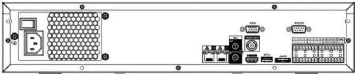
text_image
Diagram of an electronic device rear panel with labeled ports and connectors including VGA, DDR, and Ethernet portsFigure 2-52
The NVR48-16P series rear panel is shown as below. See Figure 2-53.
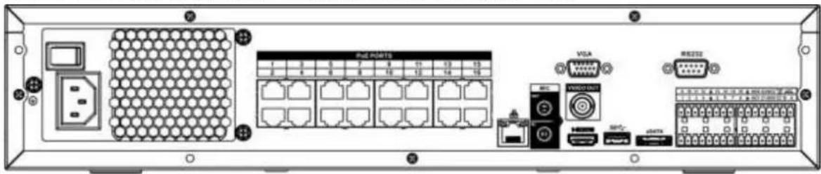
text_image
Piad Points VGA VGA VGA VGA VGA VGA VGA VGA VGA VGA VGA VGA VGA VGA VGA VGA VGA VGA VGA VGA VGA VGA VGA VGA VGA VGA VGA VGA VGA VGA VGA VGA VGA VGAFigure 2-53
Please refer to the following sheet for detailed information.
| Name | Function | |
| Power switch | / | Power on-off button |
| Power input port | / | Input AC 100~240V. |
| MIC IN | Audio input port | Bidirectional talk input port. It is to receive the analog audio signal output from the devices such as microphone, pickup. |
| MIC OUT | Audio output port | Audio output port. It is to output the analog audio signal to the devices such as the sound box.● Bidirectional talk output.● Audio output on 1-window video monitor.● Audio output on 1-window video playback. |
| VIEDEO OUT | Video output port | CVBS output. |
| 1~16 | Alarm input port1~16 | ● There are four groups. The first group is from port 1 to port 4, the second group is from port 5 to port 8, the third group is from 9 to 12, and the fourth group is from 13 to 16. They are to receive the signal from the external alarm source. There are two types; NO (normal open)/NC (normal close).● When your alarm input device is using external power, please make sure the device and the NVR have the same ground. |
| [3H4] | GND | Alarm input ground port. |
| NO1~NO5 | Alarm output port1~5 | ● 5 groups of alarm output ports. (Group 1: port NO1~C1, Group 2: port NO2~C2, Group 3: port NO3~C3, Group 4: port NO4~C4, Group 5: port NO5, C5, NC5). Output alarm signal to the alarm device. Please make sure there is power to the external alarm device.● NO: Normal open alarm output port.● C: Alarm output public end.● NC: Normal close alarm output port. |
| C1~C5 | ||
| NC5 | ||
| A | RS-485communicationport | RS485_A port. It is the cable A. You can connect to the control devices such as speed dome PTZ. |
| B | RS485_B. It is the cable B. You can connect to the control devices such as speed dome PTZ. | |
| CTRL 12V | / | Controller 12V power output. It is to control the on-off alarm relay output. It can be used to control the device alarm output. At the same time, it can also be used as the power input source of some devices such as the alarm detector. |
| +12V | / | +12V power output port. It can provide the power to some peripheral devices such as the camera or the alarm device. Please note the supplying power shall be below 1A. |
 | Network port | One 10M/100M/1000Mbps self-adaptive Ethernet port. Connect to the network cable. |
| eSATA | eSATA port | External SATA port. It can connect to the device of the SATA port. Please jump the HDD when there is peripheral connected HDD. |
| USB2.0 port | USB2.0 port. Connect to mouse, USB storage device, USB burner and etc. | |
| RS-232 | RS-232 debug COM. | It is for general COM debug to configure IP address or transfer transparent COM data. |
| HDMI | High Definition Media Interface | High definition audio and video signal output port. It transmits uncompressed high definition video and multiple-channel data to the HDMI port of the display device. HDMI version is 1.3 |
| VGA | VGA video output port | VGA video output port. Output analog video signal. It can connect to the monitor to view analog video. |
| PoE PORTS | 16 PoE ports | Built-in Switch. Support PoE. The 16 PoE ports series products supports total 150W power. One PoE port max supports 15W. |
2.2.15 NVR72 Series
The NVR72 series rear panel is shown as below. See Figure 2-54.

text_image
RS232 VGA HDMI DC124Figure 2-54
Please refer to the following sheet for detailed information.
| Name | Function | |
| USB2.0 port | USB2.0 port. Connect to mouse, USB storage device, USB burner and etc. | |
| Network port | 10M/100M/1000Mbps self-adaptive Ethernet port. Connect to the network cable. | |
| RS-232 | RS-232 debug COM. | It is for general COM debug to configure IP address or transfer transparent COM data. |
| HDMI | High Definition Media Interface | High definition audio and video signal output port. It transmits uncompressed high definition video and multiple-channel data to the HDMI port of the display device. HDMI version is 1.4. |
| VGA | VGA video output port | VGA video output port. Output analog video signal. It can connect to the monitor to view analog video. |
| MIC IN | Audio input port | Bidirectional talk input port. It is to receive the analog audio signal output from the devices such as microphone, pickup. |
| MIC OUT | Audio output port | Audio output port. It is to output the analog audio signal to the devices such as the sound box.Bidirectional talk output.Audio output on 1-window video monitor.Audio output on 1-window video playback. |
| 1~8 | Alarm input port 1~8 | There are two groups. The first group is from port 1 to port 4; the second group is from port 5 to port 8. They are to receive the signal from the external alarm source. There are two types; NO (normal open)/NC (normal close).When your alarm input device is using external power, please make sure the device and the NVR have the same ground. |
| 12 | GND | Alarm input ground port. |
| NO1~NO3 | Alarm output port 1~3 | 3 groups of alarm output ports. (Group 1: port NO1~C1, Group 2:port NO2~ C2, Group 3:port NO3~C3).Output alarm signal to the alarm device. Please make sure there is power to the external alarm device.NO: Normal open alarm output port.C: Alarm output public end. |
| C1~C3 | ||
| A | RS-485 communication port | RS485_A port. It is the cable A. You can connect to the control devices such as speed dome PTZ. |
| B | RS485_B. It is the cable B. You can connect to the control devices such as speed dome PTZ. | |
| DC 12V 12 | Power input port | Input DC 12V/5A. |
| Power switch | / | Power on/off button. |
2.2.16 NVR72-8P Series
The NVR72-8P series rear panel is shown as below. See Figure 2-55.

text_image
RS232 VGA HDMIFigure 2-55
Please refer to the following sheet for detailed information.
| Name | Function | |
 | USB2.0 port | USB2.0 port. Connect to mouse, USB storage device, USB burner and etc. |
 | Network port | 10M/100M/1000Mbps self-adaptive Ethernet port. Connect to the network cable. |
| RS-232 | RS-232 debug COM. | It is for general COM debug to configure IP address or transfer transparent COM data. |
| HDMI | High Definition Media Interface | High definition audio and video signal output port. It transmits uncompressed high definition video and multiple-channel data to the HDMI port of the display device. HDMI version is 1.4. |
| VGA | VGA video output port | VGA video output port. Output analog video signal. It can connect to the monitor to view analog video. |
| 1~8 | Alarm input port 1~8 | There are two groups. The first group is from port 1 to port 4; the second group is from port 5 to port 8. They are to receive the signal from the external alarm source. There are two types; NO (normal open)/NC (normal close).When your alarm input device is using external power, please make sure the device and the NVR have the same ground. |
| [1790] | GND | Alarm input ground port. |
| NO1~NO3 | Alarm output port 1~3 | 3 groups of alarm output ports. (Group 1: port NO1 ~ C1, Group 2: port NO2 ~ C2, Group 3: port NO3~C3). Output alarm signal to the alarm device. Please make sure there is power to the external alarm device.NO: Normal open alarm output port.C: Alarm output public end. |
| C1~C3 | ||
| A | RS-485 communication port | RS485_A port. It is the cable A. You can connect to the control devices such as speed dome PTZ. |
| B | RS485_B. It is the cable B. You can connect to the control devices such as speed dome PTZ. | |
 | Power input port | Input AC 100~240V. |
| Power switch | / | Power on-off button. |
| PoE PORTS | / | Built-in Switch. Support PoE.The 8 PoE series product supports total 48V 120W. One PoE port max supports 15W. |
| MIC IN | Audio input port | Bidirectional talk input port. It is to receive the analog audio signal output from the devices such as microphone, pickup. |
| MIC OUT | Audio output port | Audio output port. It is to output the analog audio signal to the devices such as the sound box.• Bidirectional talk output.• Audio output on 1-window video monitor.• Audio output on 1-window video playback. |
2.2.17 NVR74 Series
The NVR74 series rear panel is shown as below. See Figure 2-56.

text_image
Back panel of a network equipment module showing labeled ports, connectors, and internal components like VGA, VGA, and RS232.Figure 2-56
Please refer to the following sheet for detailed information.
| Icon | Name | Function |
| Power switch | Power on/off button. | |
| Power input port | Input AC 100~240V. | |
| MIC IN | Audio input port | Bidirectional talk input port. It is to receive the analog audio signal output from the devices such as microphone, pickup. |
| MIC OUT | Audio output port | Audio output port. It is to output the analog audio signal to the devices such as the sound box.• Bidirectional talk output.• Audio output on 1-window video monitor.• Audio output on 1-window video playback. |
| VIEDEO OUT | Video output port | CVBS output. |
| HDMI | High Definition Media Interface | High definition audio and video signal output port. It transmits uncompressed high definition video and multiple-channel data to the HDMI port of the display device. HDMI version is 1.3. |
| 1~16 | Alarm input port 1~16 | ● There are four groups. The first group is from port 1 to port 4, the second group is from port 5 to port 8, the third group is from 9 to 12, and the fourth group is from 13 to 16. They are to receive the signal from the external alarm source. There are two types; NO (normal open)/NC (normal close).● When your alarm input device is using external power, please make sure the device and the NVR have the same ground. |
| ± | GND | Alarm input ground port. |
| NO1~NO5 | Alarm output port 1~5 | ● 5 groups of alarm output ports. (Group 1: port NO1~C1, Group 2: port NO2~C2, Group 3: port NO3~C3, Group 4: port NO4~C4, Group 5: port NO5, C5, NC5). Output alarm signal to the alarm device. Please make sure there is power to the external alarm device.● NO: Normal open alarm output port.● C: Alarm output public end.● NC: Normal close alarm output port. |
| C1~C5 | ||
| NC5 | ||
| A | RS-485 communication port | RS485_A port. It is the cable A. You can connect to the control devices such as speed dome PTZ. |
| B | RS485_B. It is the cable B. You can connect to the control devices such as speed dome PTZ. | |
| CTRL 12V | / | Controller 12V power output. It is to control the on-off alarm relay output. It can be used to control the device alarm output. At the same time, it can also be used as the power input source of some devices such as the alarm detector. |
| +12V | / | +12V power output port. It can provide the power to some peripheral devices such as the camera or the alarm device. Please note the supplying power shall be below 1A. |
| Network port | One 10M/100M/1000Mbps self-adaptive Ethernet port. Connect to the network cable. | |
| eSATA | eSATA port | External SATA port. It can connect to the device of the SATA port. Please jump the HDD wher there is peripheral connected HDD. |
| USB2.0 port | USB2.0 port. Connect to mouse, USB storage device, USB burner and etc. | |
| RS-232 | RS-232 debug COM. | It is for general COM debug to configure IP address or transfer transparent COM data. |
| VGA | VGA video output port | VGA video output port. Output analog video signal. It can connect to the monitor to view analog video. |
2.2.18 NVR74-8P/74-16P Series
The NVR74-8P series rear panel is shown as below. See Figure 2-57.

text_image
Pus Portes 1 2 3 4 5 6 VGA BSS232 RBC HACETMFigure 2-57
The NVR74-16P series rear panel is shown as below. See Figure 2-58.

text_image
VGA RS2302 1 3 5 7 9 11 13 15 2 4 6 8 9 10 12 14 16 VGA RS2302 1 2 3 4 5 6 7 8 9 10 11 12 13 14 15 16 VGA RS2302 1 2 3 4 5 6 7 8 9 10 11 12 13 14 15 16 VGA RS2302 1 2 3 4 5 6 7 8 9 10 11 12 13 14 15 16Figure 2-58
Please refer to the following sheet for detailed information.
| Port Name | Function | |
| Power switch | / | Power on-off button |
| Power input port | / | Input AC 100~240V. |
| MIC IN | Audio input port | Bidirectional talk input port. It is to receive the analog audio signal output from the devices such as microphone, pickup. |
| MIC OUT | Audio output port | Audio output port. It is to output the analog audio signal to the devices such as the sound box.Bidirectional talk output.Audio output on 1-window video monitor.Audio output on 1-window video playback. |
| VIEDEO OUT | Video output port | CVBS output |
| 1~16 | Alarm input port 1~16 | There are four groups. The first group is from port 1 to port 4, the second group is from port 5 to port 8, the third group is from 9 to 12, and the fourth group is from 13 to 16. They are to receive the signal from the external alarm source. There are two types; NO (normal open)/NC (normal close).When your alarm input device is using external power, please make sure the device and the NVR have the same ground. |
| ± | GND | Alarm input ground port. |
| NO1~NO5 | Alarm output port 1~5 | 5 groups of alarm output ports. (Group 1: port NO1~C1, Group 2: port NO2~C2, Group 3: port NO3~C3, Group 4: port NO4~C4, Group 5: port NO5, C5, NC5). Output alarm signal to the alarm device. Please make sure there is power to the external alarm device.NO: Normal open alarm output port.C: Alarm output public end.NC: Normal close alarm output port. |
| C1~C5 | ||
| NC5 | ||
| A | RS-485 communication port | RS485_A port. It is the cable A. You can connect to the control devices such as speed dome PTZ. |
| B | RS485_B. It is the cable B. You can connect to the control devices such as speed dome PTZ. | |
| CTRL 12V | / | Controller 12V power output. It is to control the on-off alarm relay output. It can be used to control the device alarm output. At the same time, it can also be used as the power input source of some devices such as the alarm detector. |
| +12V | / | +12V power output port. It can provide the power to some peripheral devices such as the camera or the alarm device. Please note the supplying power shall be below 1A. |
| Network port | 10M/100M/1000Mbps self-adaptive Ethernet port. Connect to the network cable. | |
| eSATA | eSATA port | External SATA port. It can connect to the device of the SATA port. Please jump the HDD when there is peripheral connected HDD. |
| USB2.0 port | USB2.0 port. Connect to mouse, USB storage device, USB burner and etc. | |
| RS-232 | RS232 debug COM. | It is for general COM debug to configure IP address or transfer transparent COM data. |
| HDMI | High Definition Media Interface | High definition audio and video signal output port. It transmits uncompressed high definition video and multiple-channel data to the HDMI port of the display device. HDMI version is 1.3 |
| VGA | VGA video output port | VGA video output port. Output analog video signal. It can connect to the monitor to view analog video. |
| PoE PORTS | 8 PoE ports | Built-in Switch. Support PoE.The 8 PoE ports series products supports total 48V 120W power. One PoE port max supports 15W. |
| PoE PORTS | 16 PoE ports | Built-in Switch. Support PoE. The 16 PoE ports series products supports total 150W power. One PoE port max supports 15W. |
2.2.19 NVR78 Series
The NVR78 series rear panel is shown as below. See Figure 2-59.
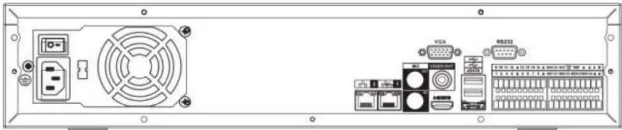
natural_image
Back view of a computer drive chassis showing front panel, rear panel with ports and connectors (no readable text or symbols)Figure 2-59
Please refer to the following sheet for detailed information.
| Port Name | Function | |
| Power switch | / | Power on-off button |
| Power input port | / | Input AC 100~240V. |
| MIC IN | Audio input port | Bidirectional talk input port. It is to receive the analog audio signal output from the devices such as microphone, pickup. |
| MIC OUT | Audio output port | Audio output port. It is to output the analog audio signal to the devices such as the sound box.Bidirectional talk output.Audio output on 1-window video monitor.Audio output on 1-window video playback. |
| VIEDEO OUT | Video output port | CVBS output |
| 1~16 | Alarm input port 1~16 | There are four groups. The first group is from port 1 to port 4, the second group is from port 5 to port 8, the third group is from 9 to 12, and the fourth group is from 13 to 16. They are to receive the signal from the external alarm source. There are two types; NO (normal open)/NC (normal close).When your alarm input device is using external power, please make sure the device and the NVR have the same ground. |
| 12 | GND | Alarm input ground port. |
| NO1~NO5 | Alarm output port | 5 groups of alarm output ports. (Group 1: port |
| C1~C5 | 1~5 | NO1~C1,Group 2:port NO2~C2,Group 3:port NO3~C3, Group 4: port NO4~C4, Group 5: port NO5, C5, NC5).Output alarm signal to the alarm device. Please make sure there is power to the external alarm device.● NO: Normal open alarm output port.● C: Alarm output public end.● NC: Normal close alarm output port. |
| NC5 | ||
| A | RS-485 communication port | RS485_A port. It is the cable A. You can connect to the control devices such as speed dome PTZ. |
| B | RS485_B.It is the cable B. You can connect to the control devices such as speed dome PTZ. | |
| CTRL 12V | / | Controller 12V power output. It is to control the on-off alarm relay output. It can be used to control the device alarm output. At the same time, it can also be used as the power input source of some devices such as the alarm detector. |
| +12V | / | +12V power output port. It can provide the power to some peripheral devices such as the camera or the alarm device. Please note the supplying power shall be below 1A. |
| Network port | 10M/100M/1000Mbps self-adaptive Ethernet port. Connect to the network cable. | |
| eSATA | eSATA port | External SATA port. It can connect to the device of the SATA port. Please jump the HDD when there is peripheral connected HDD. |
| USB2.0 port | USB2.0 port. Connect to mouse, USB storage device, USB burner and etc. | |
| RS-232 | RS-232 debug COM. | It is for general COM debug to configure IP address or transfer transparent COM data. |
| HDMI | High Definition Media Interface | High definition audio and video signal output port. It transmits uncompressed high definition video and multiple-channel data to the HDMI port of the display device. HDMI version is 1.3. |
| VGA | VGA video output port | VGA video output port. Output analog video signal. It can connect to the monitor to view analog video. |
2.2.20 NVR78-16P Series
The NVR78-16P series rear panel is shown as below. See Figure 2-60.
Figure 2-60
Please refer to the following sheet for detailed information.
| Port Name | Function | |
| Power switch | / | Power on-off button |
| Power input port | / | Input AC 100~240V. |
| MIC IN | Audio input port | Bidirectional talk input port. It is to receive the analog audio signal output from the devices such as microphone, pickup. |
| MIC OUT | Audio output port | Audio output port. It is to output the analog audio signal to the devices such as the sound box.Bidirectional talk output.Audio output on 1-window video monitor.Audio output on 1-window video playback. |
| VIEDEO OUT | Video output port | CVBS output |
| 1~16 | Alarm input port1~16 | There are four groups. The first group is from port 1 to port 4, the second group is from port 5 to port 8, the third group is from 9 to 12, and the fourth group is from 13 to 16. They are to receive the signal from the external alarm source. There are two types; NO (normal open)/NC (normal close).When your alarm input device is using external power, please make sure the device and the NVR have the same ground. |
| GND | Alarm input ground port. | |
| NO1~NO5C1~C5NC5 | Alarm output port1~5 | 5 groups of alarm output ports. (Group 1: port NO1~C1, Group 2: port NO2~C2, Group 3: port NO3~C3, Group 4: port NO4~C4, Group 5: port NO5, C5, NC5). Output alarm signal to the alarm device. Please make sure there is power to the external alarm device.NO: Normal open alarm output port.C: Alarm output public end.NC: Normal close alarm output port. |
| A | RS-485 communication port | RS485_A port. It is the cable A. You can connect to the control devices such as speed dome PTZ. |
| B | RS485_B.It is the cable B. You can connect to the control devices such as speed dome PTZ. | |
| CTRL 12V | / | Controller 12V power output. It is to control the on-off alarm relay output. It can be used to control the device alarm output. At the same time, it can also be used as the power input source of some devices such as the alarm detector. |
| +12V | / | +12V power output port. It can provide the power to some peripheral devices such as the camera or the alarm device. Please note the supplying power shall be below 1A. |
| Network port | 10M/100M/1000Mbps self-adaptive Ethernet port. Connect to the network cable. | |
| eSATA | eSATA port | External SATA port. It can connect to the device of the SATA port. Please jump the HDD when there is peripheral connected HDD. |
| USB2.0 port | USB2.0 port. Connect to mouse, USB storage device, USB burner and etc. | |
| RS-232 | RS232 debug COM. | It is for general COM debug to configure IP address or transfer transparent COM data. |
| HDMI | High Definition Media Interface | High definition audio and video signal output port. It transmits uncompressed high definition video and multiple-channel data to the HDMI port of the display device. HDMI version is 1.3 |
| VGA | VGA video output port | VGA video output port. Output analog video signal. It can connect to the monitor to view analog video. |
| PoE PORTS | 16 PoE ports | Built-in Switch. Support PoE. The 16 PoE ports series products supports total 150W power. One PoE port max supports 15W. |
2.2.21 NVR78-RH Series
The NVR78-RH series rear panel is shown as below. See Figure 2-61.
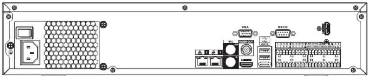
text_image
Diagram of an electronic device rear panel showing labeled ports including VGA, RS232, and network equipmentFigure 2-61
Please refer to the following sheet for detailed information.
| Port Name | Function | |
| Power switch | / | Power on-off button |
| Power input port | / | Input AC 100~240V. |
| MIC IN | Audio input port | Bidirectional talk input port. It is to receive the analog audio signal output from the devices such as microphone, pickup. |
| MIC OUT | Audio output port | Audio output port. It is to output the analog audio signal to the devices such as the sound box.Bidirectional talk output.Audio output on 1-window video monitor.Audio output on 1-window video playback. |
| VIEDEO OUT | Video output port | CVBS output |
| 1~16 | Alarm input port 1~16 | There are four groups. The first group is from port 1 to port 4, the second group is from port 5 to port 8, the third group is from 9 to 12, and the fourth group is from 13 to 16. They are to receive the signal from the external alarm source. There are two types; NO (normal open)/NC (normal close).When your alarm input device is using external power, please make sure the device and the NVR have the same ground. |
| 12 | GND | Alarm input ground port. |
| NO1~NO5 | Alarm output port 1~5 | 5 groups of alarm output ports. (Group 1: port NO1~C1, Group 2: port NO2~C2, Group 3: port NO3~C3, Group 4: port NO4~C4, Group 5: port NO5, C5, NC5). Output alarm signal to the alarm device. Please make sure there is power to the external alarm device.NO: Normal open alarm output port.C: Alarm output public end.NC: Normal close alarm output port. |
| C1~C5 | ||
| NC5 | ||
| A | RS-485 communication port | RS485_A port. It is the cable A. You can connect to the control devices such as speed dome PTZ. |
| B | RS485_B. It is the cable B. You can connect to the control devices such as speed dome PTZ. | |
| CTRL 12V | / | Controller 12V power output. It is to control the on-off alarm relay output. It can be used to control the device alarm output. At the same time, it can also be used as the power input source of some devices such as the alarm detector. |
| +12V | / | +12V power output port. It can provide the power to some peripheral devices such as the camera or the alarm device. Please note the supplying power shall be below 1A. |
| Network port | 10M/100M/1000Mbps self-adaptive Ethernet port. Connect to the network cable. | |
| eSATA | eSATA port | External SATA port. It can connect to the device of the SATA port. Please jump the HDD when there is peripheral connected HDD. |
| USB2.0 port | USB2.0 port. Connect to mouse, USB storage device, USB burner and etc. | |
| RS-232 | RS232 debug COM. | It is for general COM debug to configure IP address or transfer transparent COM data. |
| HDMI | High Definition Media Interface | High definition audio and video signal output port. It transmits uncompressed high definition video and multiple-channel data to the HDMI port of the display device. HDMI version is 1.3. The two HDMI ports to output video from different video sources. |
| VGA | VGA video output port | VGA video output port. Output analog video signal. It can connect to the monitor to view analog video. |
2.2.22 NVR70 Series
The NVR70 series rear panel is shown as below. See Figure 2-62.
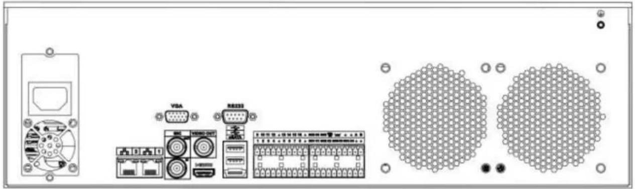
natural_image
Diagram of electronic equipment components including a front panel, VGA, and two circular connectors (no text or symbols)Figure 2-62
Please refer to the following sheet for detailed information.
| Port Name | Function | |
| Power switch | / | Power on-off button |
| Power input port | / | Input AC 100~240V. |
| MIC IN | Audio input port | Bidirectional talk input port. It is to receive the analog audio signal output from the devices such as microphone, pickup. |
| MIC OUT | Audio output port | Audio output port. It is to output the analog audio signal to the devices such as the sound box.Bidirectional talk output.Audio output on 1-window video monitor.Audio output on 1-window video playback. |
| VIEDEO OUT | Video output port | CVBS output |
| 1~16 | Alarm input port 1~16 | There are four groups. The first group is from port 1 to port 4, the second group is from port 5 to port 8, the third group is from 9 to 12, and the fourth group is from 13 to 16. They are to receive the signal from the external alarm source. There are two types; NO (normal open)/NC (normal close).When your alarm input device is using external power, please make sure the device and the NVR have the same ground. |
| ± | GND | Alarm input ground port. |
| NO1~NO5 | Alarm output port 1~5 | 5 groups of alarm output ports. (Group 1: port NO1~C1, Group 2: port NO2~C2, Group 3: port NO3~C3, Group 4: port NO4~C4, Group 5: port NO5, C5, NC5). Output alarm signal to the alarm device. Please make sure there is power to the external alarm device.NO: Normal open alarm output port.C: Alarm output public end.NC: Normal close alarm output port. |
| C1~C5 | ||
| NC5 | ||
| A | RS-485 communication port | RS485_A port. It is the cable A. You can connect to the control devices such as speed dome PTZ. |
| B | RS485_B. It is the cable B. You can connect to the control devices such as speed dome PTZ. | |
| CTRL 12V | / | Controller 12V power output. It is to control the on-off alarm relay output. It can be used to control the device alarm output. At the same time, it can also be used as the power input source of some devices such as the alarm detector. |
| +12V | / | +12V power output port. It can provide the power to some peripheral devices such as the camera or the alarm device. Please note the supplying power shall be below 1A. |
| Network port | 10M/100M/1000Mbps self-adaptive Ethernet port. Connect to the network cable. | |
| eSATA | eSATA port | External SATA port. It can connect to the device of the SATA port. Please jump the HDD when there is peripheral connected HDD. |
| USB2.0 port | USB2.0 port. Connect to mouse, USB storage device, USB burner and etc. | |
| RS-232 | RS232 debug COM. | It is for general COM debug to configure IP address or transfer transparent COM data. |
| HDMI | High Definition Media Interface | High definition audio and video signal output port. It transmits uncompressed high definition video and multiple-channel data to the HDMI port of the display device. HDMI version is 1.3 |
| VGA | VGA video output port | VGA video output port. Output analog video signal. It can connect to the monitor to view analog video. |
2.2.23 NVR70-R Series
The NVR70-R series rear panel is shown as below. See Figure 2-63.
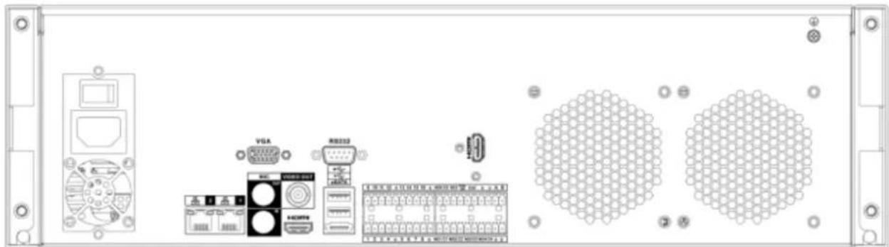
natural_image
Front view of a server rack with front panel, ports, and connectors (no visible text or symbols)Figure 2-63
Please refer to the following sheet for detailed information.
| Port Name | Function | |
| Power switch | / | Power on-off button |
| Power input port | / | Input AC 100~240V. |
| MIC IN | Audio input port | Bidirectional talk input port. It is to receive the analog audio signal output from the devices such as microphone, pickup. |
| MIC OUT | Audio output port | Audio output port. It is to output the analog audio signal to the devices such as the sound box.Bidirectional talk output.Audio output on 1-window video monitor.Audio output on 1-window video playback. |
| VIEDEO OUT | Video output port | CVBS output |
| 1~16 | Alarm input port 1~16 | There are four groups. The first group is from port 1 to port 4, the second group is from port 5 to port 8, the third group is from 9 to 12, and the fourth group is from 13 to 16. They are to receive the signal from the external alarm source. There are two types; NO (normal open)/NC (normal close).When your alarm input device is using external power, please make sure the device and the NVR have the same ground. |
| 12 | GND | Alarm input ground port. |
| NO1~NO5 | Alarm output port 1~5 | 5 groups of alarm output ports. (Group 1: port NO1~C1, Group 2: port NO2~C2, Group 3: port NO3~C3, Group 4: port NO4~C4, Group 5: port NO5, C5, NC5). Output alarm signal to the alarm device. Please make sure there is power to the external alarm device.NO: Normal open alarm output port.C: Alarm output public end.NC: Normal close alarm output port. |
| C1~C5 | ||
| NC5 | ||
| A | RS-485 communication port | RS485_A port. It is the cable A. You can connect to the control devices such as speed dome PTZ. |
| B | RS485_B. It is the cable B. You can connect to the control devices such as speed dome PTZ. | |
| CTRL 12V | / | Controller 12V power output. It is to control the on-off alarm relay output. It can be used to control the device alarm output. At the same time, it can also be used as the power input source of some devices such as the alarm detector. |
| +12V | / | +12V power output port. It can provide the power to some peripheral devices such as the camera or the alarm device. Please note the supplying power shall be below 1A. |
| Network port | 10M/100M/1000Mbps self-adaptive Ethernet port. Connect to the network cable. | |
| eSATA | eSATA port | External SATA port. It can connect to the device of the SATA port. Please jump the HDD when there is peripheral connected HDD. |
| USB2.0 port | USB2.0 port. Connect to mouse, USB storage device, USB burner and etc. | |
| RS-232 | RS232 debug COM. | It is for general COM debug to configure IP address or transfer transparent COM data. |
| HDMI | High Definition Media Interface | High definition audio and video signal output port. It transmits uncompressed high definition video and multiple-channel data to the HDMI port of the display device. HDMI version is 1.3. The two HDMI ports to output video from different video sources. |
| VGA | VGA video output port | VGA video output port. Output analog video signal. It can connect to the monitor to view analog video. |
2.2.24 NVR42V-8P Series
The interface is shown as in Figure 2-64.
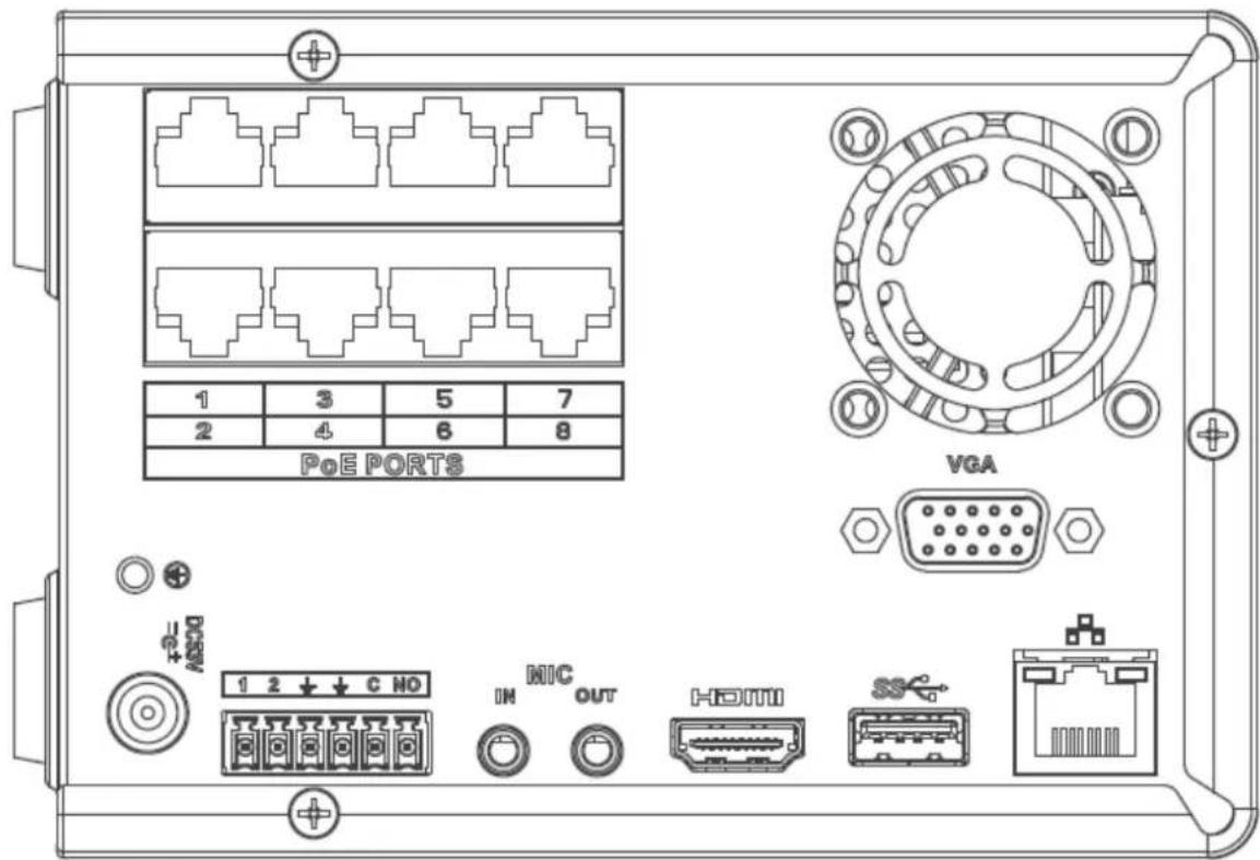
text_image
PoE PORTS VGA 1 2 3 4 5 6 7 NIC OUT HDMI SSFigure 2-64
Please refer to the following sheet for detailed information.
| Name | Function | |
| Power switch | / | Power on/off button. |
| DC53V=@* | Power input port | Input DC 53V--2.3A |
| MIC IN | Audio input port | Bidirectional talk input port. It is to receive the analog audio signal output from the devices such as microphone, pickup. |
| MIC OUT | Audio output port | Audio output port. It is to output the analog audio signal to the devices such as the sound box.Bidirectional talk output.Audio output on 1-window video monitor.Audio output on 1-window video playback. |
| 1~2 | Alarm input port1~2 | When your alarm input device is using external power, please make sure the device and the NVR have the same ground. |
| ± | GND | Alarm input ground port. |
| C | Alarm output public port | Alarm output public end. |
| NO | Normal open | Normal open alarm output port. |
| Network port | 10M/100M/1000Mbps self-adaptive Ethernet port. Connect to the network cable. | |
| USB3.0 port | USB3.0 port. Connect to mouse, USB storage device, USB burner and etc. | |
| HDMI | High Definition Media Interface | High definition audio and video signal output port. It transmits uncompressed high definition video and multiple-channel data to the HDMI port of the display device. HDMI version is 1.4. |
| VGA | VGA video output port | VGA video output port. Output analog video signal. It can connect to the monitor to view analog video. |
| PoE PORT | / | Bult-in Switch. Support PoE.The 8 PoE series product supports total 48V 120W.One PoE port max supports 15W. |
2.3 Alarm Connection
2.3.1 Alarm Port
The alarm port is shown as below. See Figure 2-65. The following figure is based on the 78 series.
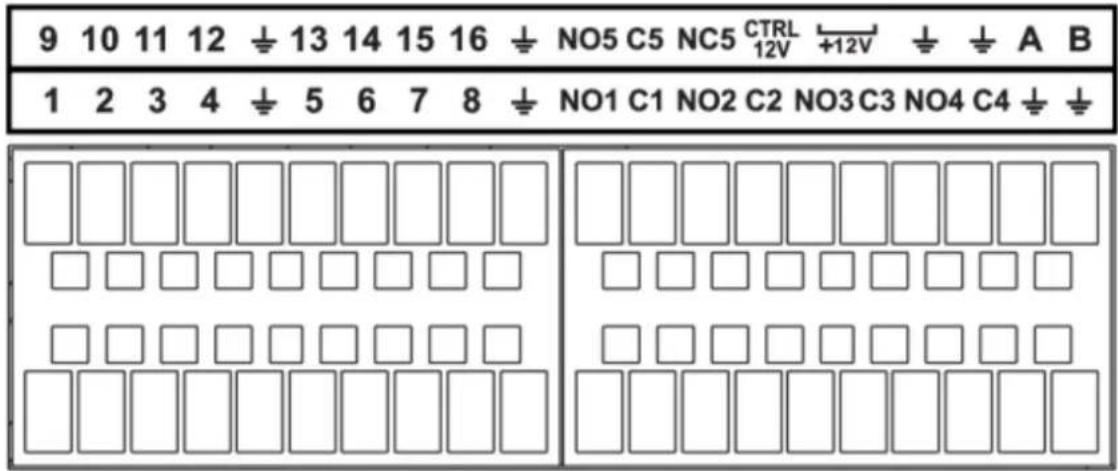
| Icon | Function |
| 1~16 | ALARM1~ALARM16. The alarm becomes activated in the low level. |
| NO1 C1, NO2 C2, NO3 C3, NO4 C4 | Four NO activation output groups. (On-off button). |
| NO5 C5 NC5 | One NO/NC activation output group. (On-off button). |
| CTRL 12V | Control power output. Disable power output when alarm is canceled. Current is 500mA. |
| +12V | Rated current output. Current is 500mA. |
 | GND |
| A/B | 485 communication port. They are used to control devices such as PTZ. Please parallel connect 120TΩ between A/B cables if there are too many PTZ decoders. |
Note
- Different models support different alarm input ports. Please refer to the specifications sheet for detailed information.
- Slight difference may be found on the alarm port layout.
2.3.2 Alarm input port
Connect the positive end (+) of the alarm input device to the alarm input port (ALARM IN 1\~16) of the
NVR. Connect the negative end (-) of the alarm input device to the ground end ( ) of the NVR.
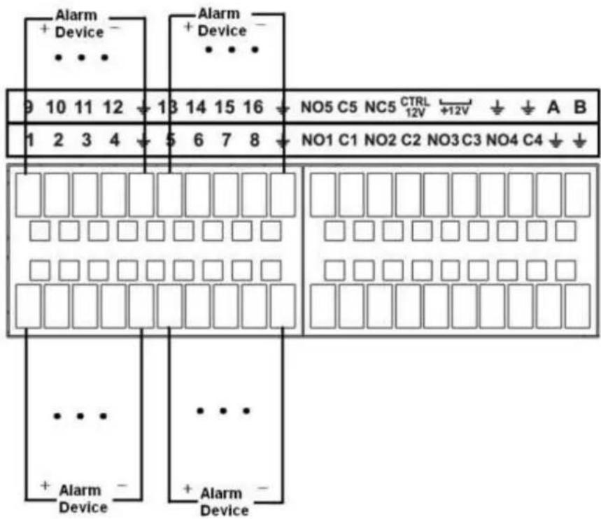
text_image
Alarm + Device - • • • Alarm + Device - • • • 9 10 11 12 13 14 15 16 NO5 C5 NC5 CTRL 12V +12V ↓ ↓ A B 1 2 3 4 5 6 7 8 NO1 C1 NO2 C2 NO3 C3 NO4 C4 ↓ ↓ • • • + Alarm - Device • • • + Alarm - DeviceFigure 2-66
Note
● There are two alarm input types: NO/NC.
- When connect the ground port of the alarm device to the NVR, you can use any of the GND ports

- Connect the NC port of the alarm device to the alarm input port (ALARM) of the NVR.
- When there is peripheral power supplying for the alarm device, please make sure it is earthed with the NVR.
2.3.3 Alarm input and output port
● There is peripheral power supplying for the external alarm device.
- In case overload may result in NVR damage, please refer to the following relay specifications for detailed information.
● A/B cable of the RS485 is for the A/B cable connection of the speed PTZ.
2.3.4 Alarm relay specifications
| Model: JRC-27F | ||
| Material of the touch | Silver | |
| Rating (Resistance Load) | Rated switch capacity | 30VDC 2A, 125VAC 1A |
| Maximum switch power | 125VA 160W | |
| Maximum switch voltage | 250VAC, 220VDC | |
| Maximum switch currency | 1A | |
| Insulation | Between touches with same polarity | 1000VAC 1minute |
| Between touches with different polarity | 1000VAC 1minute | |
| Between touch and winding | 1000VAC 1minute | |
| Surge voltage | Between touches with same polarity | 1500V (10×160us) |
| Length of open time | 3ms max | |
| Length of close time | 3ms max | |
| Longevity | Mechanical | 50×106 MIN (3Hz) |
| Electrical | 200×103 MIN (0.5Hz) | |
| Temperature | -40°C ~+70°C | |
2.4 Bidirectional talk
2.4.1 Device-end to PC-end
Device Connection
Please connect the speaker or the pickup to the first audio input port in the device rear panel. Then connect the earphone or the sound box to the audio output port in the PC.
Login the Web and then enable the corresponding channel real-time monitor.
Please refer to the following interface to enable bidirectional talk. See Figure 2-67.
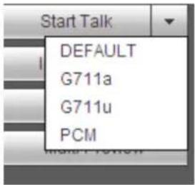
text_image
Start Talk DEFAULT G711a G711u PCMFigure 2-67
Listening Operation
At the device end, speak via the speaker or the pickup, and then you can get the audio from the earphone or sound box at the pc-end. See Figure 2-68.

flowchart
graph LR
    A["Server"] -->|Data Link| B["Internet"]
    B --> C["Computer"]
Figure 2-68
2.4.2 PC-end to the device-end
Device Connection
Connect the speaker or the pickup to the audio output port in the PC and then connect the earphone or the sound box to the first audio input port in the device rear panel.
Login the Web and then enable the corresponding channel real-time monitor.
Please refer to the above interface (Figure 2-67) to enable bidirectional talk.
Listening Operation
At the PC-end, speak via the speaker or the pickup, and then you can get the audio from the earphone or sound box at the device-end. See Figure 2-69.
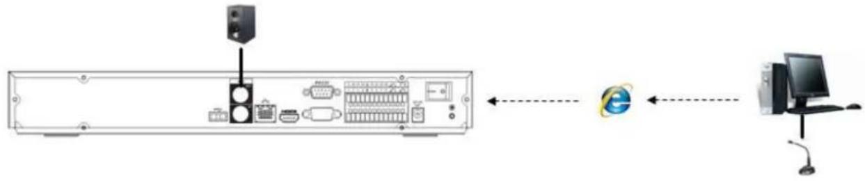
flowchart
graph LR
    A["Server"] --> B["Port 1"]
    B --> C["Port 2"]
    C --> D["Port 3"]
    D --> E["Port 4"]
    E --> F["Port 5"]
    F --> G["Port 6"]
    G --> H["Port 7"]
    H --> I["Port 8"]
    I --> J["Port 9"]
    J --> K["Port 10"]
    K --> L["Port 11"]
    L --> M["Port 12"]
    M --> N["Port 13"]
    N --> O["Port 14"]
    O --> P["Port 15"]
    P --> Q["Port 16"]
    Q --> R["Port 17"]
    R --> S["Port 18"]
    S --> T["Port 19"]
    T --> U["Port 20"]
    U --> V["Port 21"]
    V --> W["Port 22"]
    W --> X["Port 23"]
    X --> Y["Port 24"]
    Y --> Z["Port 25"]
Figure 2-69
2.5 Mouse Operation
Please refer to the following sheet for mouse operation instruction.
| Left click mouse | When you have selected one menu item, left click mouse to view menu content. |
| Modify checkbox or motion detection status. | |
| Click combo box to pop up dropdown list | |
| In input box, you can select input methods. Left click the corresponding button on the panel you can input numeral/English character (small/capitalized). Here← stands for backspace button. _ stands for space button.In English input mode: _stands for input a backspace icon and ← stands for deleting the previous character. | |
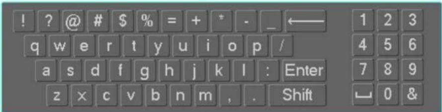 | |
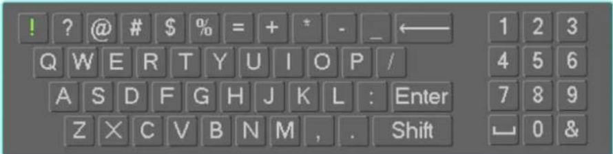 | |
| In numeral input mode: _ stands for clear and ← stands for deleting the previous numeral. | |
| Double left click mouse | Implement special control operation such as double click one item in the file list to playback the video. |
alhua
| In multiple-window mode, double left click one channel to view in full-window. Double left click current video again to go back to previous multiple-window mode. | |
| Right click mouse | In real-time monitor mode, pops up shortcut menu. |
| Exit current menu without saving the modification. | |
| Press middle button | In numeral input box: Increase or decrease numeral value. |
| Switch the items in the check box. | |
| Page up or page down | |
| Move mouse | Select current control or move control |
| Drag mouse | Select motion detection zone |
| Select privacy mask zone. |
2.6 Remote Control
The remote control interface is shown as in Figure 2-70.
Please note remote control is not our standard accessory and it is not included in the accessory bag.
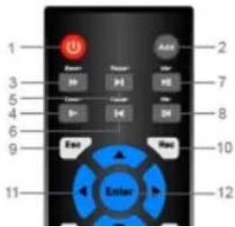
text_image
1 2 3 4 5 6 7 8 9 10 11 Enter 12| 3 | Forward | Various forward speeds and normal speed playback. |
| 4 | Slow play | Multiple slow play speeds or normal playback. |
| 5 | Next record | In playback mode, playback the next video. |
| 6 | Previous record | In playback mode, playback the previous video. |
| 7 | Play/Pause | In pause mode, click this button to realize normal playback. |
| In normal playback click this button to pause playback. | ||
| In real-time monitor mode, click this button to enter video search menu. | ||
| 8 | Reverse/pause | Reverse playback pause mode, click this button to realize normal playback. |
| In reverse playback click this button to pause playback. | ||
| 9 | Esc. | Go back to previous menu or cancel current operation (close upper interface or control) |
| 10 | Record | Start or stop record manually In record interface, working with the direction buttons to select the record channel. Click this button for at least 1.5 seconds, system can go to the Manual Record interface. |
| 11 | Direction keys | Switch current activated control, go to left or right. In playback mode, it is to control the playback process bar. Aux function(such as switch the PTZ menu) |
| 12 | Enter /menu key | go to default button go to the menu |
| 13 | Multiple-window switch | Switch between multiple-window and one-window. |
| 14 | Fn | In 1-ch monitor mode: pop up assistant function: PTZ control and Video color. |
| Switch the PTZ control menu in PTZ control interface. | ||
| In motion detection interface, working with direction keys to complete setup. | ||
| In text mode, click it to delete character. | ||
| 15 | 0-9 number key | Input password, channel or switch channel. |
| Shift is the button to switch the input method. |
3 Device Installation
Note: All the installation and operations here should conform to your local electric safety rules.
3.1 Check Unpacked NVR
When you receive the NVR from the forwarding agent, please check whether there is any visible damage. The protective materials used for the package of the NVR can protect most accidental clashes during transportation. Then you can open the box to check the accessories.
Please check the items in accordance with the list. Finally you can remove the protective film of the NVR.
3.2 About Front Panel and Rear Panel
The model number in the stick on the bottom of NVR is very important; please check according to your purchase order.
The label in the rear panel is very important too. Usually we need you to represent the serial number when we provide the service after sales.
3.3 HDD Installation
Important:
Please turn off the power before you replace the HDD.
The pictures listed below for reference only.
For the first time install, please be aware that whether the HDDs have been installed.
You can refer to the Appendix for HDD space information and recommended HDD brand. Please use HDD of 7200rpm or higher. Usually we do not recommend the PC HDD.
Please follow the instructions below to install hard disk.
3.3.1 NVR100/100-P Series

Please make sure the metal surface of the HDD is facing up when you are installing!
This series NVR has only one 2.5-inch SATA HDD.
Please follow the instructions below to install HDD.

natural_image
Hand holding a dark rectangular object with a white base, against a plain white background (no text or symbols visible)①Draw out the HDD bracket
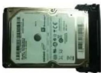
text_image
324.00 12 24 0+1②Make sure the HDD metal
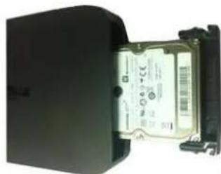
natural_image
Exterior view of a black electronic device with a metallic connector and ports (no visible text or symbols)③ Put the HDD into the device
surface is facing up and then put the HDD into the bracket
horizontally. After the HDD is in the proper position, the columns on the two sides can lock the screw holes of the HDD to secure it.
When you remove the HDD, please refer to the following figure to pull the spring up and then remove the HDD.
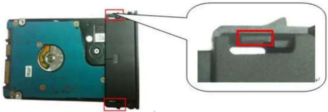
natural_image
Close-up of a hard disk computer case with a close-up inset showing internal components (no text or symbols visible)3.3.2 NVR11/11-P/41/41-P/41-8P/41-W/21-S2/21-P-S2/21-8P-S2 Series
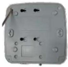
natural_image
Close-up of a gray electronic device casing with mounting holes and a central button (no visible text or symbols)①. Loosen the screws of the upper cover and side panel.
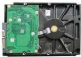
natural_image
Interior view of a computer drive showing internal components including a green circuit board and black fan (no text or symbols visible)② Fix four screws in the HDD (Turn just three rounds).
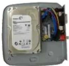
natural_image
Interior view of an electronic device showing a CD-ROM drive and internal wiring (no visible text or symbols)③ Place the HDD in accordance with the four holes in the bottom.
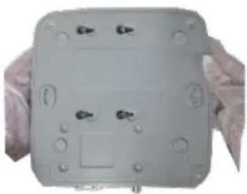
natural_image
Close-up of hands holding a gray electronic device casing with buttons and mounting holes (no visible text or symbols)④ Turn the device upside down and then turn the screws in firmly.
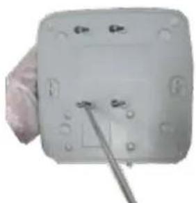
natural_image
Close-up of a white electronic device with screw holes and a metal screwdriver inserted (no visible text or symbols)⑤ Fix the HDD firmly.
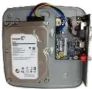
natural_image
Interior view of a computer case showing internal components and wiring (no readable text or symbols)⑥ Connect the HDD cable and power cable.
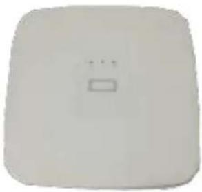
natural_image
Plain white rectangular object with a small rectangular cutout on the side (no text or symbols)
natural_image
Close-up of a gray electronic device casing with buttons and a central display (no visible text or symbols)⑦ Put the cover in accordance with
⑧ Secure the screws in the rear panel and the side panel.
the clip and then place the upper cover back.
3.3.3 NVR11H/11H-P/41H/41H-P/41H-8P/11HS/21HS-S2/21HS-P-S2/21HS-8P-S2 Series
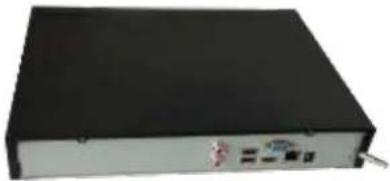
natural_image
Black rectangular electronic device with ports and a cable, no visible text or symbols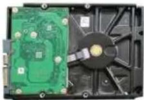
natural_image
Interior view of a computer drive showing green circuit board and black fan (no visible text or symbols)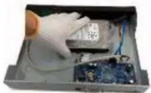
natural_image
Hand in gloves handling electronic components inside a metal enclosure (no visible text or symbols)①. Loosen the screws of the upper cover and side panel.
② Fix four screws in the HDD
(Turn just three rounds).
③ Place the HDD in accordance with the four holes in the bottom.
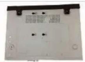
natural_image
Top-down view of a white electronic device casing with mounting holes and ventilation grilles (no text or symbols visible)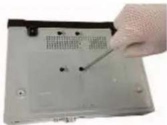
natural_image
Close-up of a hand holding a screwdriver inserted into a computer drive (no visible text or symbols)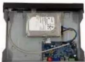
natural_image
Interior view of an electronic device showing a circuit board with wires and a labeled component (no visible text or symbols)④ Turn the device upside down and then turn the screws in firmly.
⑤ Fix the HDD firmly.
⑥ Connect the HDD cable and power cable.
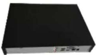
natural_image
Black rectangular electronic device with a metallic grille and small indicator lights (no visible text or symbols)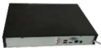
natural_image
Black rectangular electronic device with a small white label on the side (no visible text or symbols)⑦ Put the cover in accordance with the clip and then place the upper cover back.
⑧ Secure the screws in the rear panel and the side panel.
3.3.4 NVR42/42N/42-P/42-8P/42-16P/72/72-8P/42-4K/42-8P-4K/52-4KS2/52-8P-4KS2/52-16P-4KS2/22-S2/22-P-S2/22-8P-S2 Series
The following figures are based on the NVR 72-8P series.
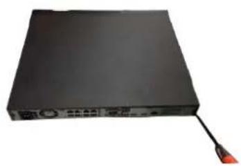
natural_image
Black electronic device with ports and a red-tipped cable (no visible text or symbols)① Loosen the screws of the upper cover and side panel.
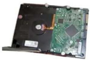
natural_image
Interior view of a hard disk drive showing internal components including a CPU, motherboard, and fan (no visible text or symbols)② Fix four screws in the HDD (Turn just three rounds).
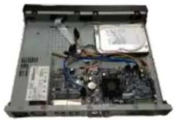
natural_image
Interior view of a computer case showing internal components like CPU, motherboard, and memory (no visible text or labels)③Place the HDD in accordance with the four holes in the bottom.
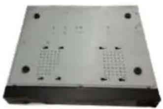
natural_image
Exterior view of a rectangular electronic device casing with mounting holes and internal compartments (no text or symbols visible)④Turn the device upside down and then turn the screws in firmly.
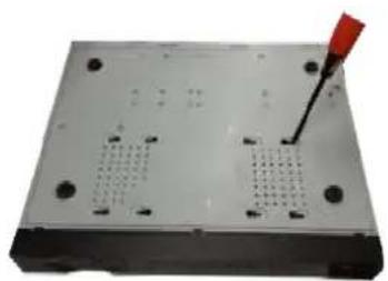
natural_image
Exterior view of a rectangular electronic device with four slots and a red screwdriver inserted (no text or symbols visible)⑤Fix the HDD firmly.
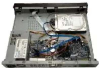
natural_image
Interior view of an open computer case showing internal components like CPU socket, motherboard, and drive bays (no visible text or labels)⑥Connect the HDD cable and power cable.
natural_image
Black rectangular electronic device with a slot, shown against a white background (no text or symbols visible)⑦Put the cover in accordance with the clip and then place the upper cover back.
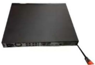
natural_image
Black electronic device with a cable and indicator lights, no visible text or symbols on the body.⑧Secure the screws in the rear panel and the side panel.
3.3.5 NVR44/44-8P/44-16P/74/74-8P/74-16P/44-4K/54-4KS2/54-16P-4KS2 Series
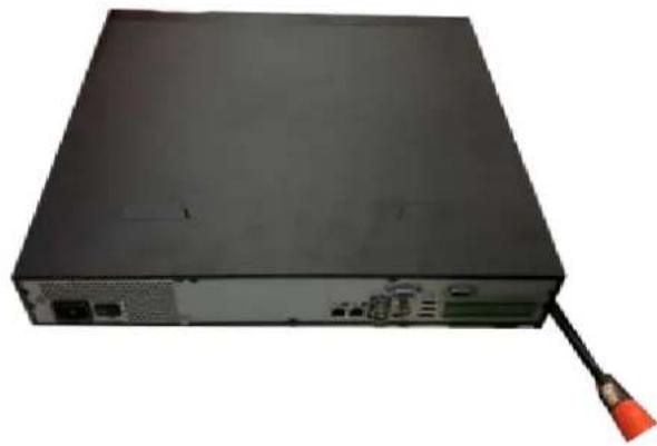
natural_image
Back view of a black server rack with attached cable and ports (no visible text or labels)① Use the screwdriver to loose the screws of the rear panel and then remove the front cover.
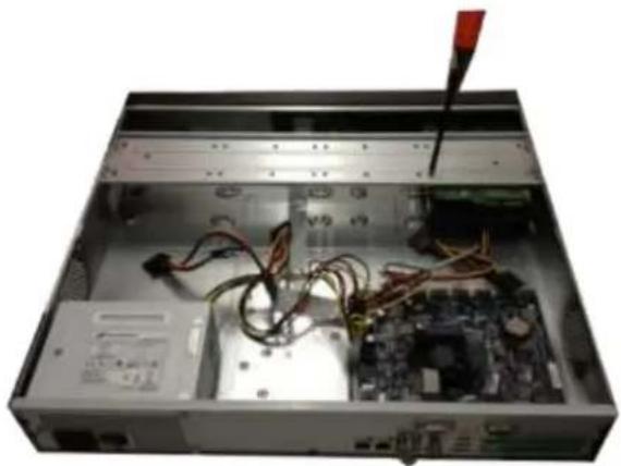
natural_image
Interior view of a computer tower case with visible circuit board and cable, no text or symbols present② Put the HDD to the HDD bracket in the chassis and then line up the four screws to the four holes in the HDD. Use the screwdriver to fix the screws firmly to secure HDD on the HDD bracket
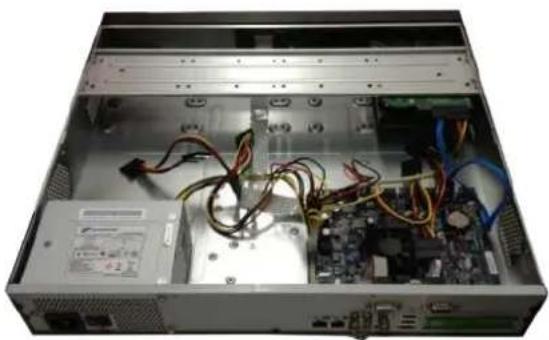
natural_image
Interior view of a server rack with exposed circuit board and cable, no visible text or symbols③ Connect to the HDD data cable to the main board and the HDD port respectively. Loosen the power cable of the chassis and connect another end of the power cable to the HDD port.
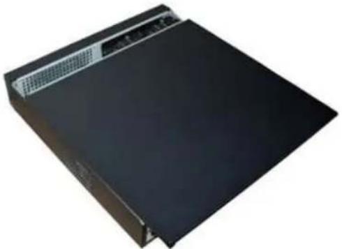
natural_image
Exterior view of a black electronic device with ventilation grilles (no visible text or symbols)④ After connect the cable, put the front cover back to the device and then fix screws of the rear panel.
3.3.6 NVR48/48-16P/NVR78/78-16P/48-4K/58-4KS2/58-16P-4KS2 Series The following figures are based on the NVR78 series.
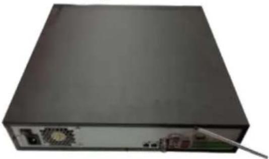
natural_image
Exterior view of a black server or network device with a power connector and indicator lights (no visible text or symbols)① Use the screwdriver to loose the screws of the rear panel and then remove the front cover.
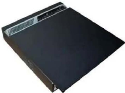
natural_image
Black rectangular electronic device with a top panel and control buttons (no visible text or symbols)② ②Put the HDD to the HDD bracket in the chassis and then line up the four screws to the four holes in the HDD. Use the screwdriver to fix the screws firmly to secure HDD on the HDD bracket
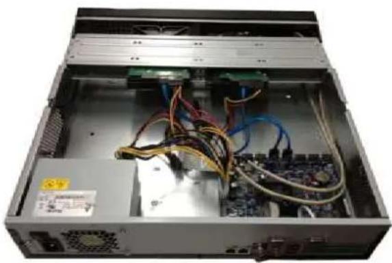
natural_image
Interior view of a server rack with exposed circuit board and cable, no visible text or labels③Connect to the HDD data cable to the main board and the HDD port respectively. Loosen the power cable of the chassis and connect another end of the power cable to the HDD port.
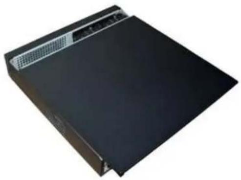
natural_image
Exterior view of a black rectangular electronic device with a textured top and base (no visible text or symbols)④After connect the cable, put the front cover back to the device and then fix screws of the rear panel.
3.3.7 NVR78-RH Series
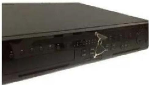
natural_image
Black electronic device with control panel and indicator lights (no visible text or symbols)①Turn the key into the hole in the front panel.
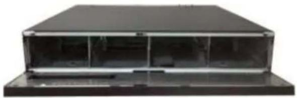
natural_image
Exterior view of a black rectangular electronic device with transparent glass casing (no visible text or symbols)②Open the front panel.
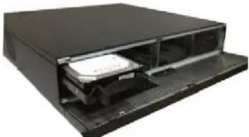
natural_image
Black electronic device with open lid and internal components (no visible text or symbols)③ Put the HDD to the slot and adjust the handle to secure it.
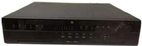
natural_image
Black electronic device with control panel and buttons (no visible text or labels)④Put the front panel back and use the key to fix firmly.
HDD Handle Installation
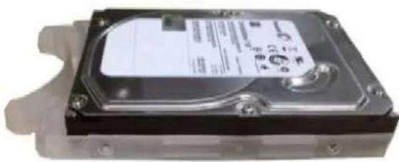
natural_image
Close-up of a hard disk drive chassis with visible internal components and mounting brackets (no readable text or symbols)①Line up the handle to the HDD side (without the interface)
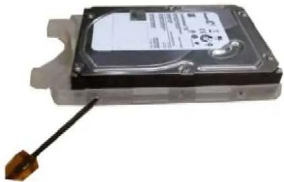
natural_image
Exterior view of a hard disk drive with visible internal components and a cable (no text or symbols)②Use the screwdriver to fix the handle on the HDD.
3.3.8 NVR70/70-R Series
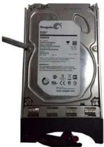
text_image
SEAGATA 3000G8 www.segate.com①Use four screws to secure the HDD.
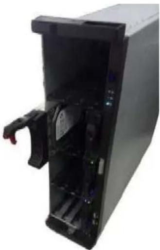
natural_image
Interior view of a black server or computer tower with visible internal components and a red handle (no text or symbols)②Put the HDD to the HDD box at the front panel of the device. .
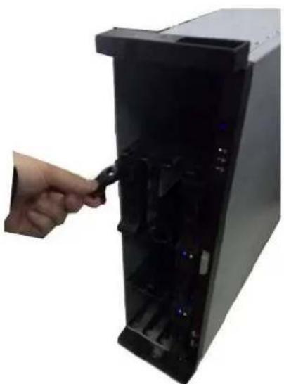
natural_image
Hand inserting a cable into a black server rack unit (no text or symbols visible)③Please pull the handle up when you are inputting the HDD box in case the the handle
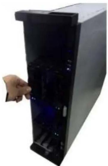
natural_image
Hand inserting a drive into a black server rack (no text or symbols visible)④Put the HDD to the HDD box at the front panel of the device. .
collides with the front panel
3.3.9 NVR42V-8P Series
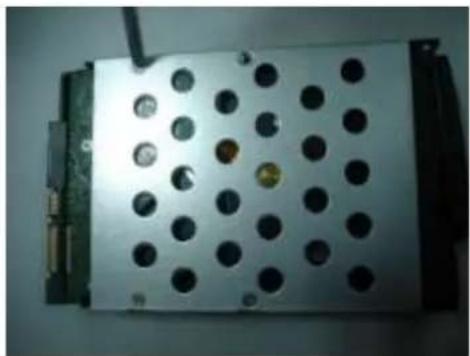
natural_image
Exterior view of a white electronic device with perforated panel and connectors (no visible text or symbols)①Use 4 screws to secure the HDD
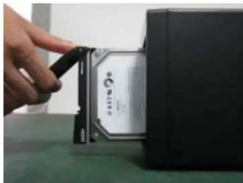
natural_image
Close-up of a hand inserting a CPU into a black processor unit (no visible text or symbols)②Put the HDD to the HDD box at the front.
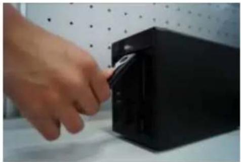
natural_image
Hand inserting a black plastic into a black rectangular device (no text or symbols visible)③Pull the HDD knob up when you put the HDD into the box in case the knob buckle may strike the front panel.
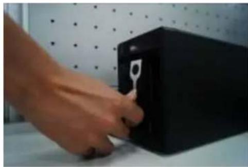
natural_image
Hand inserting a black file into a white box on a white surface, with a dotted wall and window in the background (no text or symbols visible)④Put the knob back after you insert the HDD to the SATA board.
3.4 CD-ROM Installation
Please follow the steps listed below.
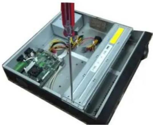
natural_image
Interior view of an electronic device showing internal components like circuit boards, wires, and a red tool (no visible text or symbols)① Open top cover and then remove the HDD bracket
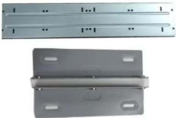
natural_image
Two metallic metal components: a flat panel with four horizontal slots and a flanged cover with mounting holes (no text or symbols visible)② Take off the bottom of the HDD bracket and CD-ROM bracket.
ajhua
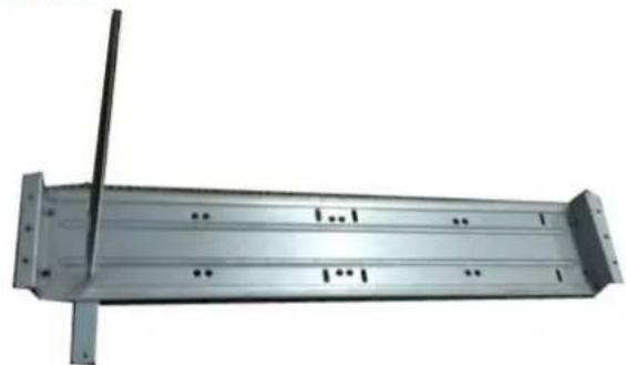
natural_image
Metal beam with support structure and vertical rod, no visible text or symbols③ Fix the CD-ROM bracket at the HDD bracket.
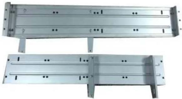
natural_image
Two metallic structural panels with internal channels and mounting holes, shown from different angles (no text or symbols visible)④ Install a pair of the CD-ROM bracket. Please make sure the reverse side is secure too.
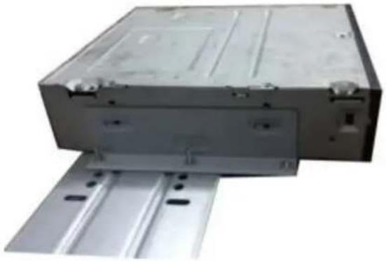
natural_image
Exterior view of a gray electronic device with mounting brackets and metal rails (no visible text or symbols)⑤ Install SATA burner. Line up the SATA burner to the hole positions.
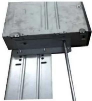
natural_image
Mechanical assembly with a metallic block mounted on a metal frame, supported by two vertical rods (no visible text or symbols)⑥ User screwdriver to fix the screws.
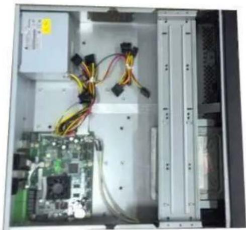
natural_image
Interior view of an electronic device showing a circuit board, power connectors, and server racks (no visible text or symbols)⑦ Put the bracket back. Please adjust the CD-ROM to the proper position so that the button of the front panel is directly facing the pop-up button of the CD-ROM.
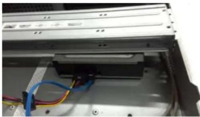
natural_image
Close-up of a computer drive bay with visible cable and indicator lights (no text or symbols)⑧ Connect the SATA cable and power wire.
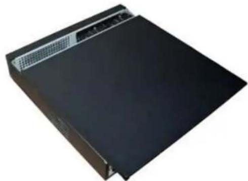
natural_image
Exterior view of a black server or laptop device with a small screen top (no visible text or symbols)⑨ Secure the HDD bracket and put the top cover back.
3.5 Connection Sample
3.5.1 NVR100/NVR100-P Series
Please refer to Figure 3-1 for connection sample.
Here we take NVR100-P as an example.
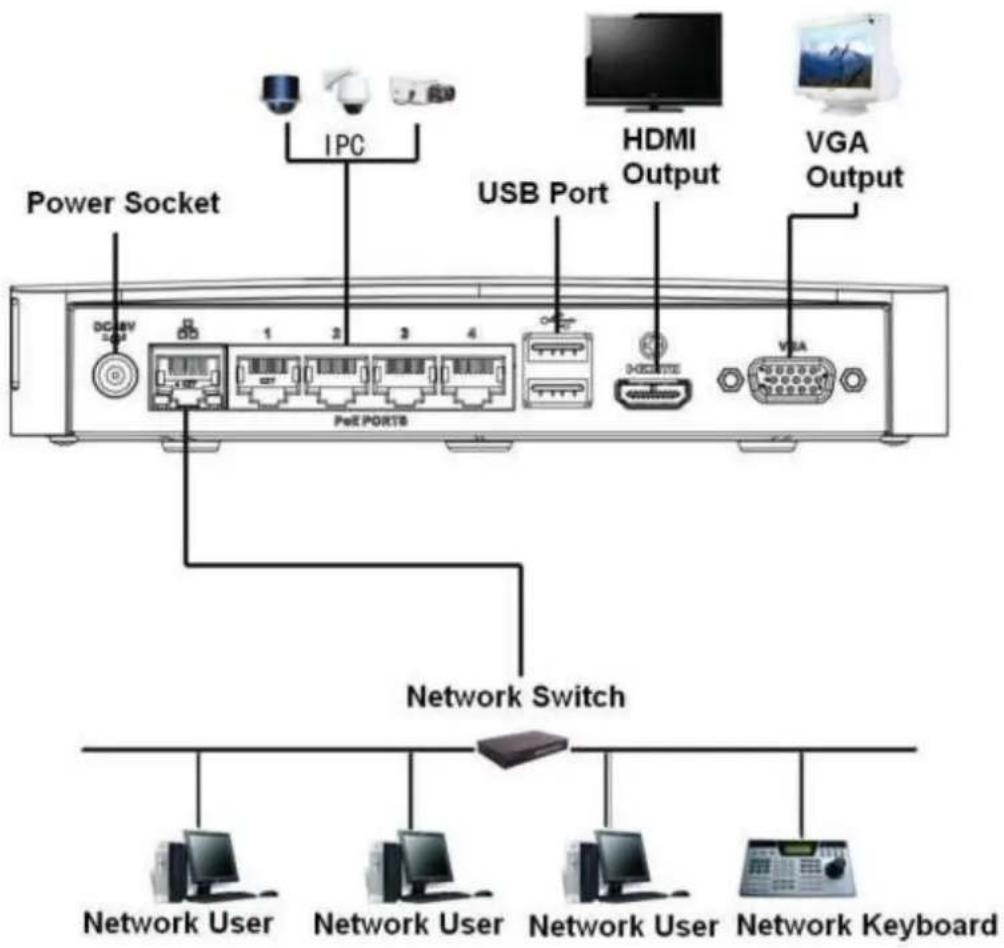
text_image
Power Socket IPC USB Port HDMI Output VGA Output PeE PORTB Network Switch Network User Network User Network User Network KeyboardFigure 3-1
3.5.2 NVR11/11-P/41/41-P/41-8P/41-W/21-S2/21-P-S2/21-8P-S2 Series
Please refer to Figure 3-2 for connection sample.
Here we take NVR41 as an example.
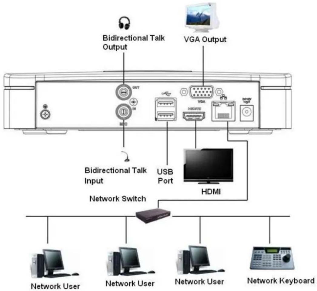
text_image
Bidirectional Talk Output VGA Output Bidirectional Talk Input USB Port HDMI Network Switch Network User Network User Network User Network KeyboardFigure 3-2
3.5.3 NVR11H/11H-P/41H/41H-P/41H-8P Series
Please refer to Figure 3-3 for connection sample.
Here we take NVR41H as an example.
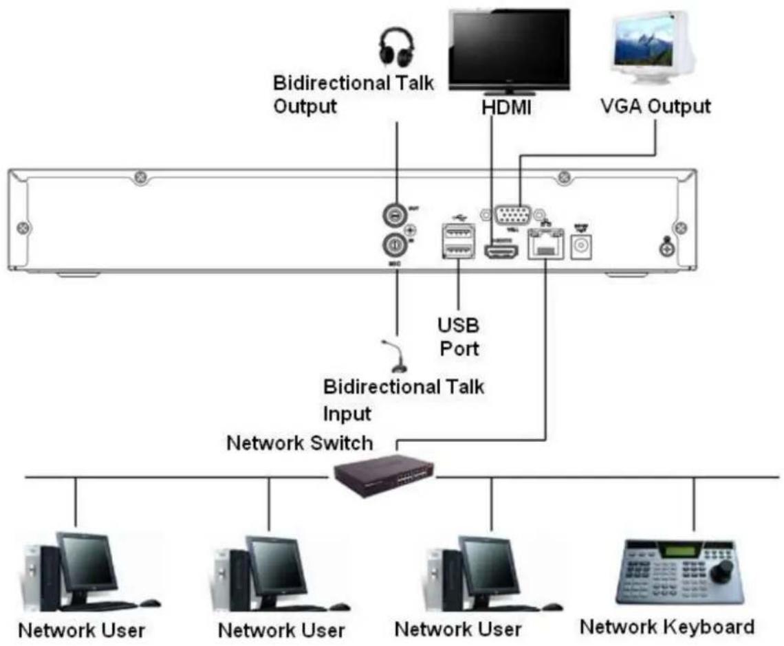
flowchart
graph TD
    A["Bidirectional Talk Output"] --> B["USB Port"]
    C["HDMI"] --> B
    D["VGA Output"] --> B
    B --> E["Bidirectional Talk Input"]
    E --> F["Network Switch"]
    F --> G["Network User"]
    F --> H["Network User"]
    F --> I["Network User"]
    F --> J["Network Keyboard"]
Figure 3-3
3.5.4 NVR11HS Series
Please refer to Figure 3-4 for connection sample.
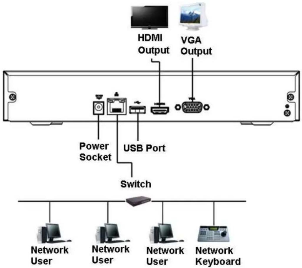
text_image
HDMI Output VGA Output Power Socket USB Port Switch Network User Network User Network User Network KeyboardFigure 3-4
3.5.5 NVR21HS-S2/21HS-P-S2/21HS-8P-S2 Series
Please refer to Figure 3-5 for connection sample.
Please note the following figure is based on the NVR21HS-8P-S2.
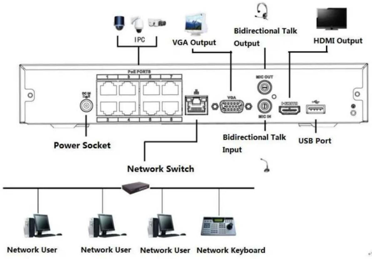
text_image
IPC VGA Output Bidirectional Talk Output HDMI Output PoE PORTB VGA MIC OUT Power Socket NIC IN DOSKOUT USB Port Network Switch Network User Network User Network User Network KeyboardFigure 3-5
3.5.6 NVR22-S2/22-P-S2/22-8P-S2 Series
Please refer to Figure 3-6 for connection sample.
Please note the following figure is based on the NVR22-8P-S2.
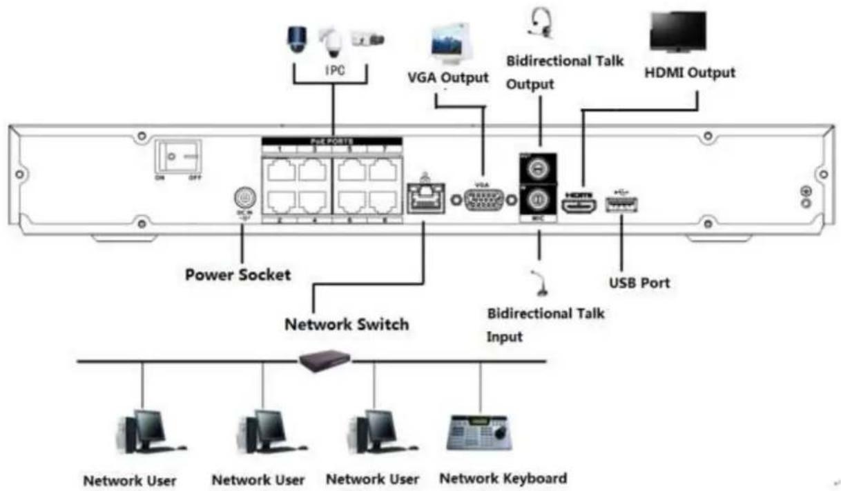
text_image
IPC VGA Output Bidirectional Talk Output HDMI Output ON OFF Power Socket Network Switch Bidirectional Talk Input USB Port Network User Network User Network User Network KeyboardFigure 3-6
3.5.7 NVR42N Series
Please refer to Figure 3-7 for connection sample.
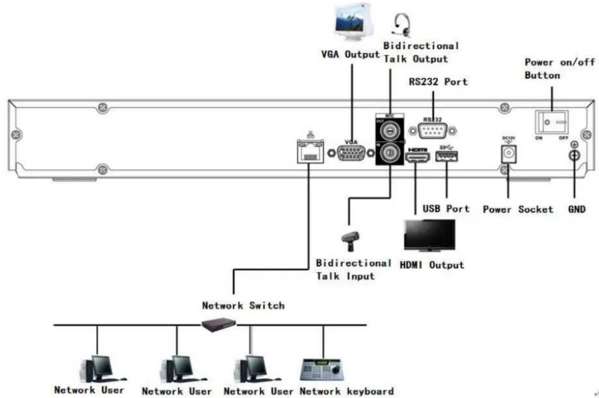
text_image
VGA Output Bidirectional Talk Output RS232 Port Power on/off Button USB Port Power Socket GND Bidirectional Talk Input HDMI Output Network Switch Network User Network User Network User Network keyboardFigure 3-7
3.5.8 NVR42/42-P/42-8P/42-16P/52-4KS2/52-8P-4KS2/52-16P-4KS2 Series
Please refer to Figure 3-8 for connection sample.
The following figure is based on our 42-8P series product.
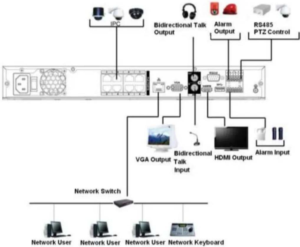
flowchart
graph TD
    A["Network User"] --> B["Network Switch"]
    C["Network Keyboard"] --> B
    D["IPC"] --> E["Bidirectional Talk Output"]
    F["RS485 PTZ Control"] --> G["Alarm Output"]
    H["VGA Output"] --> I["Bidirectional Talk Input"]
    J["HDMI Output"] --> K["Alarm Input"]
    L["ICU"] --> M["Radio System"]
    N["Radio Head"] --> O["Radio System"]
Figure 3-8
3.5.9 NVR42-4K Series
Please refer to Figure 3-9 for connection sample.
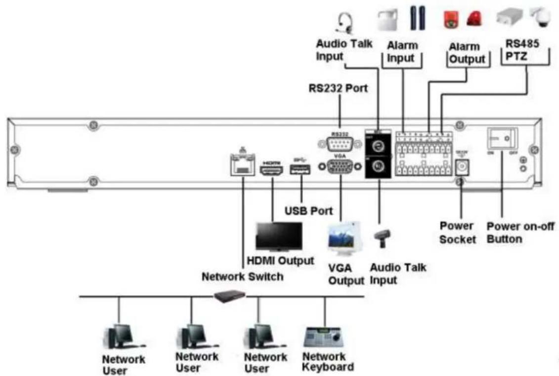
text_image
Audio Talk Input Alarm Input Alarm Output RS485 PTZ RS232 Port USB Port HDMI Output VGA Output Audio Talk Input Power Socket Power on-off Button Network Switch Network User Network Keyboard Network UserFigure 3-9
3.5.10 NVR42-8P-4K Series
Please refer to Figure 3-10 for connection sample.
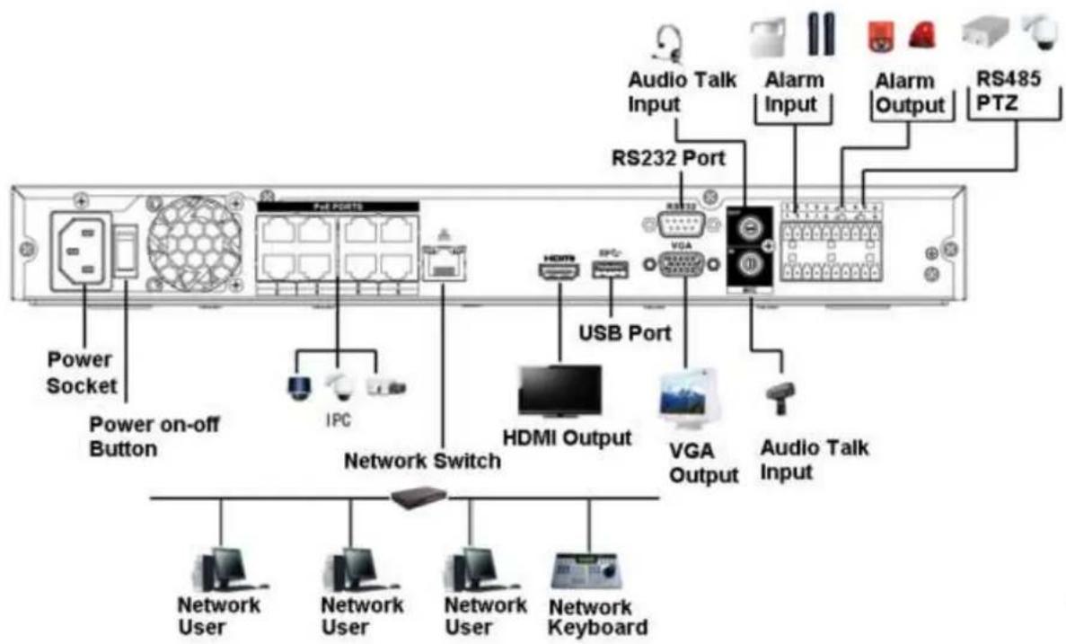
text_image
Power Socket Power on-off Button IPC Network Switch HDMI Output VGA Output USB Port Audio Talk Input RS232 Port RS485 PTZ Alarm Input Alarm Output Audio Talk Input Network User Network Keyboard Network User Network KeyboardFigure 3-10
3.5.11 NVR44-4K/48-4K/54-4KS2/54-16P-4KS2/58-4KS2/58-16P-4KS2 Series
Please refer to Figure 3-10 for connection sample.
The following interface is based on the 44-4K series product.
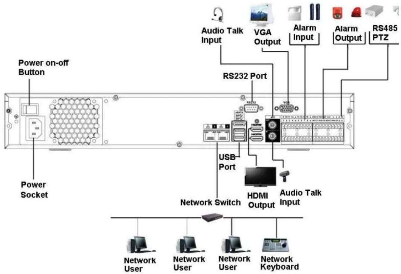
text_image
Power on-off Button Power Socket Audio Talk Input VGA Output RS232 Port USB Port Network Switch HDMI Output Audio Talk Input Network User Network User Network User Network KeyboardFigure 3-11
3.5.12 NVR44/44-8P/44-16P Series
Please refer to Figure 3-12 for connection sample.
The following interface is based on the 44-8P series product.
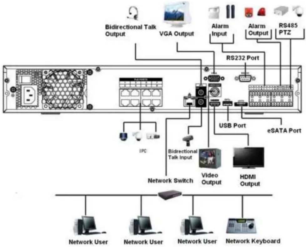
flowchart
graph TD
    A["Network User"] --> B["Network Keyboard"]
    C["Network User"] --> D["Network Keyboard"]
    E["Network Switch"] --> F["Video Output"]
    G["IPC"] --> H["Bidirectional Talk Input"]
    I["RS232 Port"] --> J["USB Port"]
    K["HS/MI Output"] --> L["eSATA Port"]
    M["Bidirectional Talk Output"] --> N["VGA Output"]
    O["Alarm Input"] --> P["RS485 PTZ"]
    Q["Network Keyboard"] --> R["Network Keyboard"]
Figure 3-12
3.5.13 NVR48/48-16P Series
Please refer to Figure 3-13 for connection sample.
The following interface is based on the 48-16P series product.
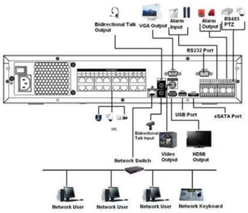
flowchart
graph TD
    A["User Interface"] --> B["Bidirectional Talk Output"]
    A --> C["VGA Output"]
    A --> D["Alarm Input"]
    A --> E["Alarm Output"]
    A --> F["RS485 PTZ"]
    A --> G["RS232 Port"]
    A --> H["USB Port"]
    A --> I["eSATA Port"]
    A --> J["IPC"]
    A --> K["Bidirectional Talk Input"]
    K --> L["Video Output"]
    K --> M["HDMI Output"]
    A --> N["Network Switch"]
    A --> O["Network User"]
    A --> P["Network Keyboard"]
    style A fill:#f9f,stroke:#333
    style I fill:#ccf,stroke:#333
Figure 3-13
3.5.14 NVR72 Series
Please refer to Figure 3-14 for connection sample.
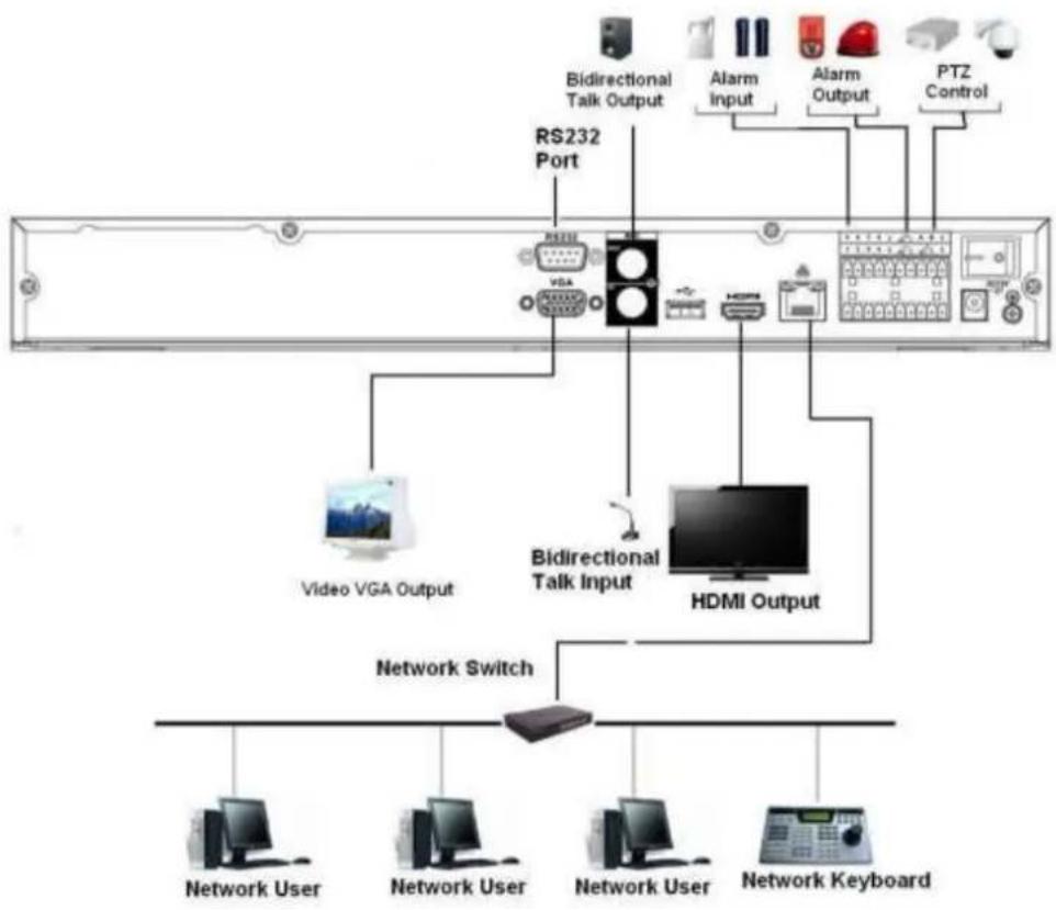
flowchart
graph TD
    A["Bidirectional Talk Output"] --> B["RS232 Port"]
    C["Alarm Input"] --> B
    D["Alarm Output"] --> B
    E["PTZ Control"] --> B
    B --> F["Video VGA Output"]
    B --> G["HDMI Output"]
    G --> H["Network Switch"]
    H --> I["Network User"]
    H --> J["Network User"]
    H --> K["Network User"]
    H --> L["Network Keyboard"]
Figure 3-14
3.5.15 NVR72-8P Series
Please refer to Figure 3-15 for connection sample.
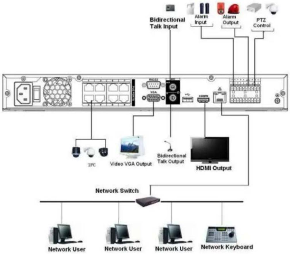
flowchart
graph TD
    A["Back panel"] --> B["Bidirectional Talk Input"]
    A --> C["Video VGA Output"]
    A --> D["HDMI Output"]
    B --> E["IPC"]
    B --> F["Alarm Input"]
    B --> G["Alarm Output"]
    B --> H["PTZ Control"]
    C --> I["Network Switch"]
    D --> I
    E --> J["Network User"]
    F --> K["Network User"]
    G --> L["Network User"]
    H --> M["Network Keyboard"]
Figure 3-15
3.5.16 NVR74 Series
Please refer to Figure 3-16 for connection sample.
The following figure is based on the 74 series product.
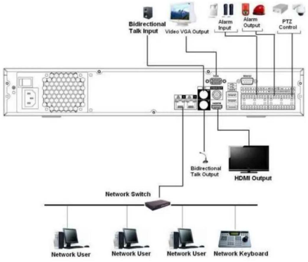
flowchart
graph TD
    A["Network Switch"] --> B["Bidirectional Talk Input"]
    A --> C["Video VGA Output"]
    A --> D["Alarm Input"]
    A --> E["Alarm Output"]
    A --> F["PTZ Control"]
    A --> G["HDMI Output"]
    B --> H["Network User"]
    C --> I["Network User"]
    D --> J["Network User"]
    E --> K["Network Keyboard"]
    F --> L["End"]
Figure 3-16
3.5.17 NVR74-8P/74-16P Series
Please refer to Figure 3-17 for connection sample.
The following figure is based on the NVR74-8P series product.
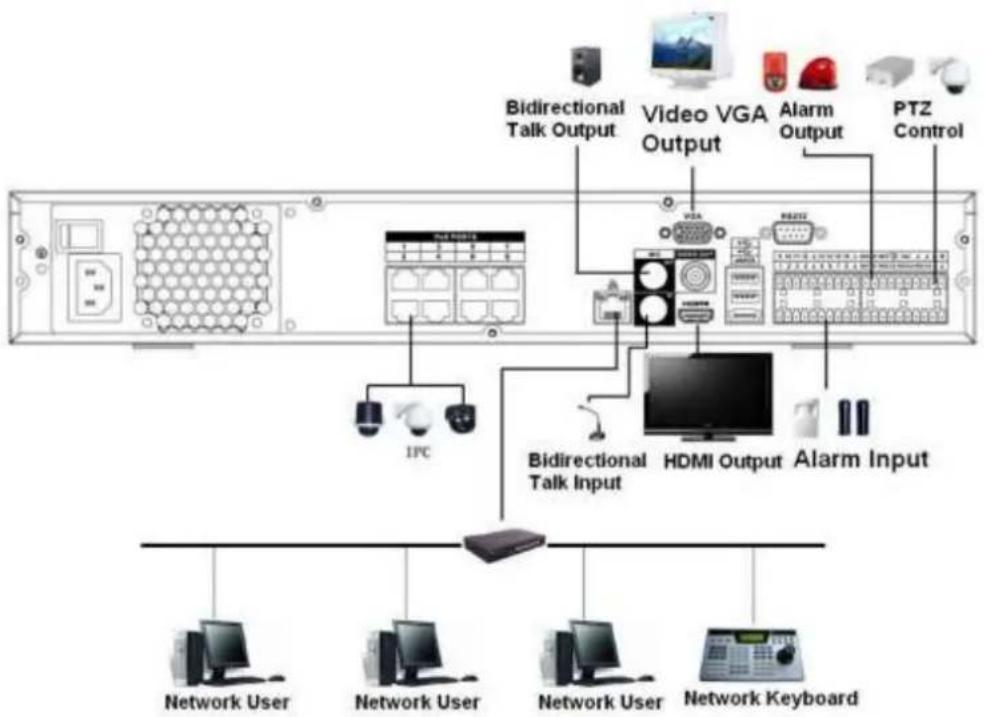
flowchart
graph TD
    A["Network User"] --> B["Network Keyboard"]
    C["Network User"] --> D["Network Keyboard"]
    E["Network User"] --> F["Network Keyboard"]
    G["IPC"] --> H["Bidirectional Talk Input"]
    I["Video VGA Output"] --> J["HDMI Output"]
    K["Alarm Output"] --> L["PTZ Control"]
    M["Bidirectional Talk Output"] --> N["Video VGA Output"]
    O["Network User"] --> P["Network Keyboard"]
Figure 3-17
3.5.18 NVR78 Series
Please refer to Figure 3-18 for connection sample.
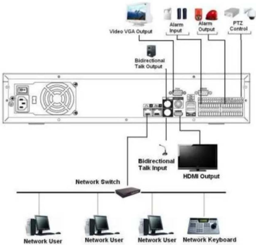
flowchart
graph TD
    A["TV System"] --> B["Video VGA Output"]
    A --> C["Bidirectional Talk Output"]
    C --> D["Alarm Input"]
    C --> E["Alarm Output"]
    C --> F["PTZ Control"]
    D --> G["Computer"]
    E --> H["Computer"]
    F --> I["Computer"]
    G --> J["Network User"]
    H --> K["Network User"]
    I --> L["Network Keyboard"]
Figure 3-18
3.5.19 NVR78-16P Series
Please refer to Figure 3-19 for connection sample.

text_image
Power Switch GND Power Socket Fan IPC Bidirectional Talk Output Video Output VGA Output USB Port RS232 eSATA RS485 PTZ Control HDMI Output Bidirectional Talk Input Online User Online User Online User Network Keyboard Online UserFigure 3-19
3.5.20 NVR78-RH Series
Please refer to Figure 3-20 for connection sample.
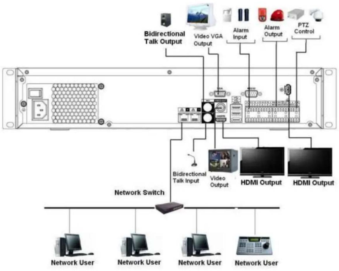
flowchart
graph TD
    A["Network Switch"] --> B["Bidirectional Talk Input"]
    A --> C["Video Output"]
    A --> D["HDMI Output"]
    A --> E["PTZ Control"]
    B --> F["Network User"]
    C --> G["Network User"]
    D --> H["Network User"]
    E --> I["Network User"]
    style A fill:#f9f,stroke:#333
    style B fill:#ccf,stroke:#333
    style C fill:#cfc,stroke:#333
    style D fill:#fcc,stroke:#333
    style E fill:#cff,stroke:#333
Figure 3-20
3.5.21 NVR70 Series
Please refer to Figure 3-21 for connection sample.
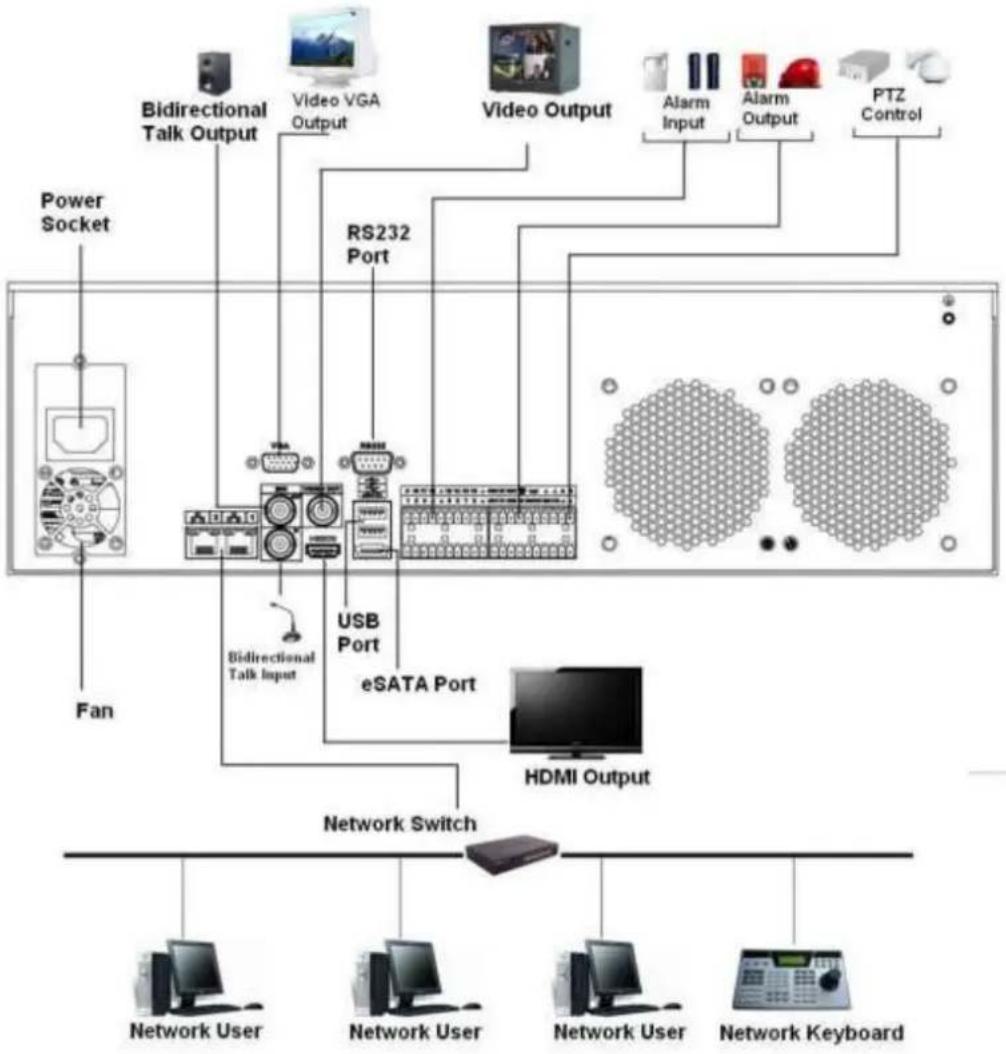
flowchart
graph TD
    A["Power Socket"] --> B["Bidirectional Talk Output"]
    B --> C["Video VGA Output"]
    C --> D["RS232 Port"]
    D --> E["USB Port"]
    E --> F["eSATA Port"]
    F --> G["HDMI Output"]
    G --> H["Network Switch"]
    H --> I["Network User"]
    H --> J["Network User"]
    H --> K["Network User"]
    H --> L["Network Keyboard"]
    M["Bidirectional Talk Input"] --> N["USB Port"]
    O["PTZ Control"] --> P["Alarm Input"]
    O --> Q["Alarm Output"]
Figure 3-21
3.5.22 NVR70-R Series
Please refer to Figure 3-22 for connection sample.
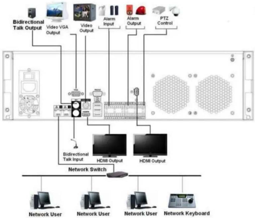
flowchart
graph TD
    A["Bidirectional Talk Output"] --> B["Video VGA Output"]
    B --> C["Video Output"]
    C --> D["Alarm Input"]
    D --> E["Alarm Output"]
    E --> F["PTZ Control"]
    C --> G["Bidirectional Talk Input"]
    G --> H["HDMI Output"]
    G --> I["HDMI Output"]
    H --> J["Network Switch"]
    I --> J
    K["Network User"] --> J
    L["Network User"] --> J
    M["Network User"] --> J
    N["Network Keyboard"] --> J
Figure 3-22
3.5.23 NVR42V-8P Series
Please refer to Figure 3-23 for connection sample.
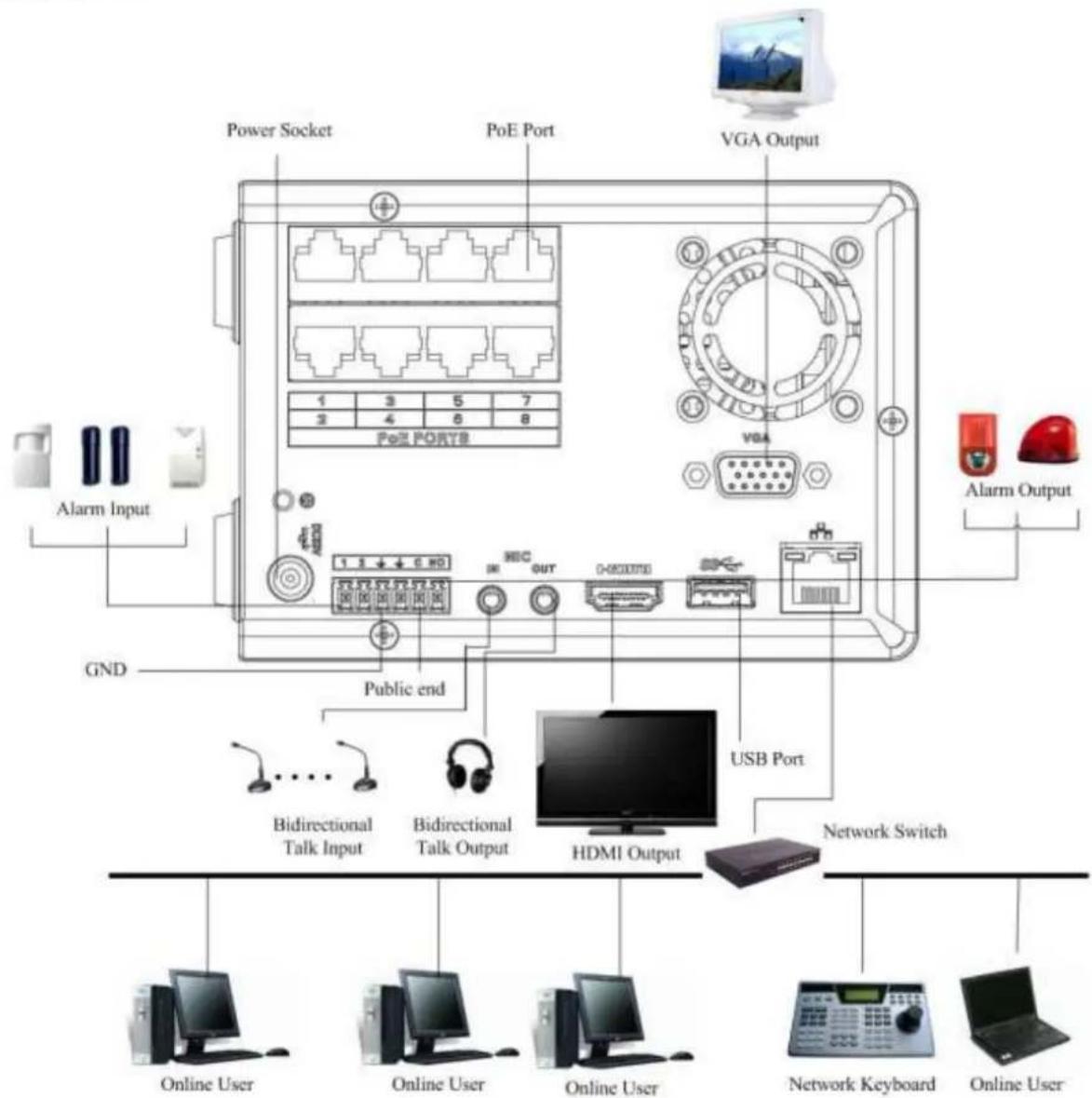
text_image
Power Socket PoE Port VGA Output 1 3 5 7 2 4 6 8 PoE PORTB VGA Alarm Input GND Public end USB Port Network Switch Bidirectional Talk Input Bidirectional Talk Output HDMI Output Online User Online User Online User Network Keyboard Online UserFigure 3-23
4 Local Basic Operation
4.1 Boot up and Shutdown
4.1.1 Boot up
Before the boot up, please make sure:
- For device security, please connect the NVR to the power adapter first and then connect the device to the power socket.
- The rated input voltage matches the device power on-off button. Please make sure the power wire connection is OK. Then click the power on-off button.
● Always use the stable current, if necessary UPS is a best alternative measure.
Please follow the steps listed below to boot up the device.
- Connect the device to the monitor and then connect a mouse.
- Connect power cable.
- Click the power button at the front or rear panel and then boot up the device. After device booted up, the system is in multiple-channel display mode by default.
4.1.2 Shutdown
Note
- When you see corresponding dialogue box "System is shutting down..." Do not click power on-off button directly.
- Do not unplug the power cable or click power on-off button to shutdown device directly when device is running (especially when it is recording.)
There are three ways for you to log out.
a) Main menu (RECOMMENDED)
From Main Menu->Shutdown, select shutdown from dropdown list.
Click OK button, you can see device shuts down.
b) From power on-off button on the front panel or remote control.
Press the power on-off button on the NVR front panel or remote control for more than 3 seconds to shutdown the device.
c) From power on-off button on the rear panel.
4.2 Change/Reset Password
4.2.1 Change Password
For your own safety, please change your administrator default password after your first login.
After system booted up, you can see the following interface if it is your first login or you have restored default setup. See Figure 4-1. Please input old password and then input new password twice to confirm the change.
● The default administrator user name is admin and the password is admin.
- You can set security questions here to reset the password in case you forgot. System supports customized setup. Please note you need to set two security questions at the same time. When you reset the password, you need to answer these two security questions too.
- For reset information, please refer to chapter 4.2.2.
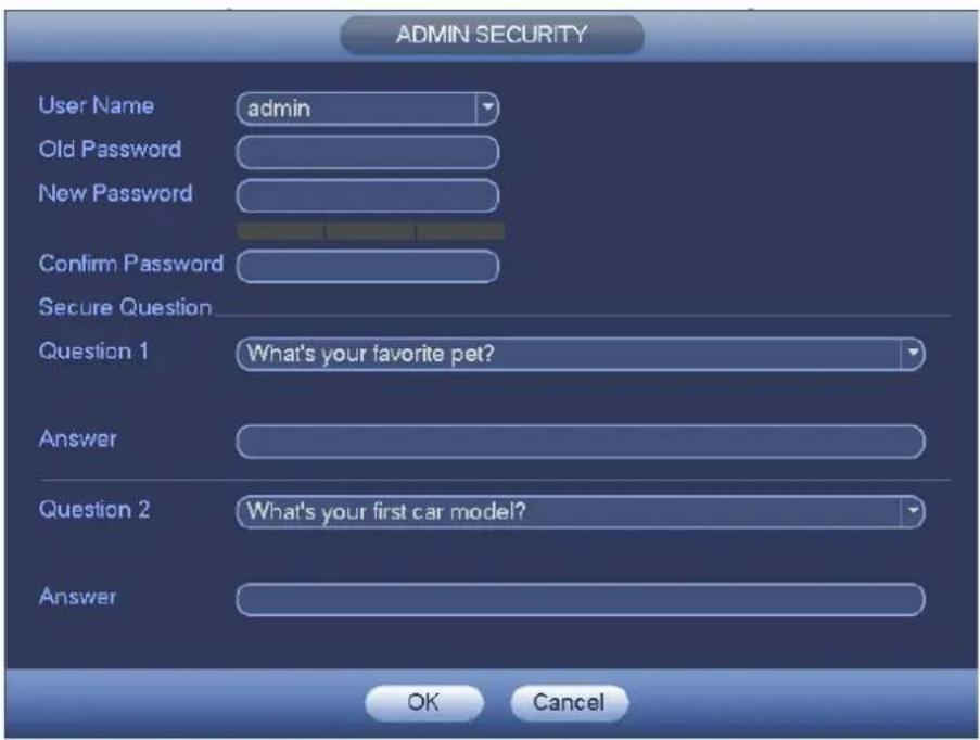
text_image
ADMIN SECURITY User Name admin Old Password New Password Confirm Password Secure Question Question 1 What's your favorite pet? Answer Question 2 What's your first car model? Answer OK CancelFigure 4-1
Click Cancel button, system pops up the following interface for you to confirm. See Figure 4-2. Check the box here, system will not pop up the change password interface the next time.
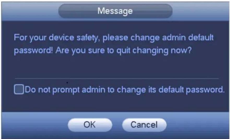
text_image
Message For your device safety, please change admin default password! Are you sure to quit changing now? Do not prompt admin to change its default password. OK CancelFigure 4-2
4.2.2 Reset Password
Once you forgot password, you can answer the security questions you set in chapter 4.2.1 to reset the password.
In login interface, click. See Figure 4-3.
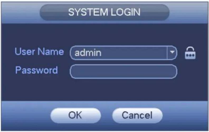
text_image
SYSTEM LOGIN User Name admin Password OK CancelFigure 4-3
System pops up the following dialogue box, please answer the security questions and then input the new password twice. See Figure 4-4.
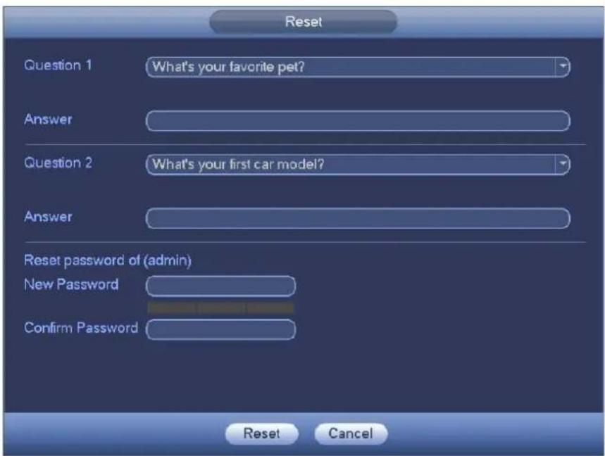
text_image
Reset Question 1 What's your favorite pet? Answer Question 2 What's your first car model? Answer Reset password of (admin) New Password Confirm Password Reset CancelFigure 4-4
4.3 Startup Wizard
After device successfully booted up, it goes to startup wizard.
Click Cancel/Next button, you can see system goes to login interface.
Tips
Check the box Startup button here, system goes to startup wizard again when it boots up the next time.
Cancel the Startup button, system goes to the login interface directly when it boots up the next time.
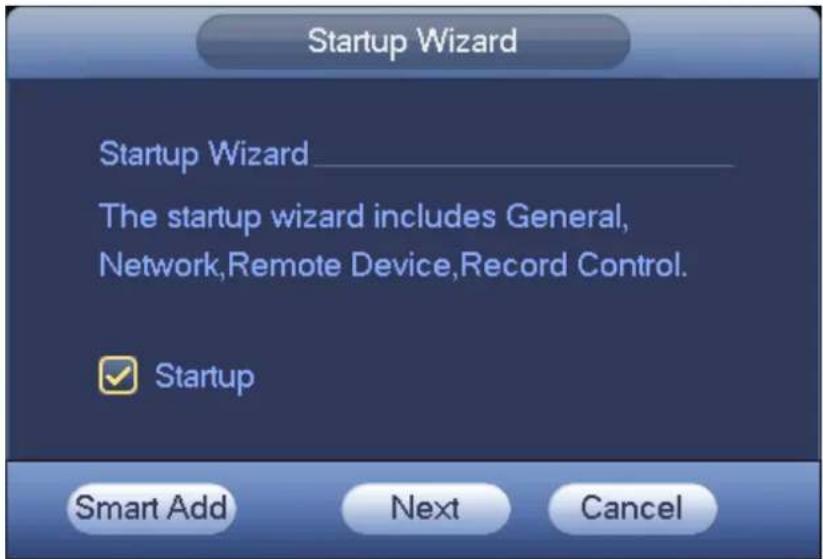
text_image
Startup Wizard Startup Wizard The startup wizard includes General, Network,Remote Device,Record Control. Startup Smart Add Next CancelFigure 4-5
Click Smart add, Cancel button or Next button, system goes to login interface. See Figure 4-6. System consists of three accounts:
- Username: admin. Password: admin. (administrator, local and network)
- Username: 888888. Password: 888888. (administrator, local only)
- Username: default. Password: default (hidden user). Hidden user "default" is for system interior use only and can not be deleted. When there is no login user, hidden user "default" automatically login. You can set some rights such as monitor for this user so that you can view some channel view without login.
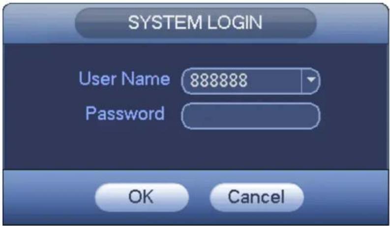
text_image
SYSTEM LOGIN User Name 888888 Password OK CancelFigure 4-6
Note:
For security reason, please modify password after you first login.
Within 30 minutes, three times login failure will result in system alarm and five times login failure will result in account lock!
For detailed smart add information, please refer to chapter 4.5. Click OK button, you can go to General interface. See Figure 4-7. For detailed information, please refer to chapter 4.16.1.
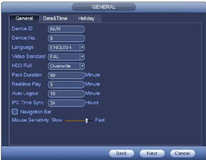
text_image
GENERAL General Date&Time Holiday Device ID NVR Device No. 8 Language ENGLISH Video Standard PAL HDD Full Overwrite Pack Duration 60 Minute Realtime Play 5 Minute Auto Logout 10 Minute IPC Time Sync 24 Hours Navigation Bar Mouse Sensitivity Slow Fast Back Next CancelFigure 4-7
Click Next button, you can go to network interface. See Figure 4-8.
For detailed information, please refer to chapter 4.14.
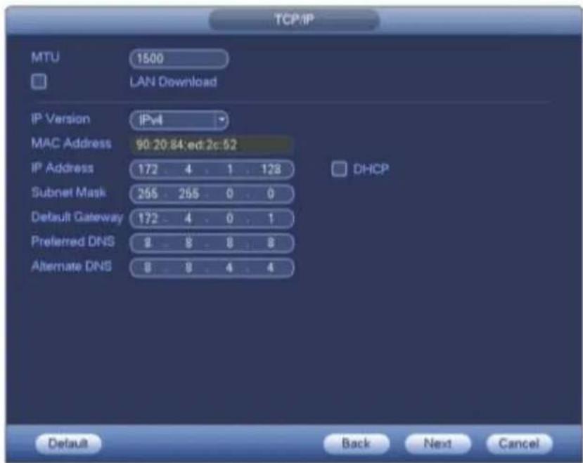
text_image
TCP/IP MTU 1500 LAN Download IP Version IPv4 MAC Address 90:20:84:ed:2c:52 IP Address 172 4 1 128 Subnet Mask 265 265 0 0 Default Gateway 172 4 0 1 Preferred DNS 8 8 8 8 Alternate DNS 8 8 4 4 DHCP Default Back Next CancelFigure 4-8
Click Next button, you can set P2P function. Scan the QR code, download the App to the cellphone, you can use the smart phone to add the device. See Figure 4-9.
For detailed information, please refer to chapter 4.14.1.16.
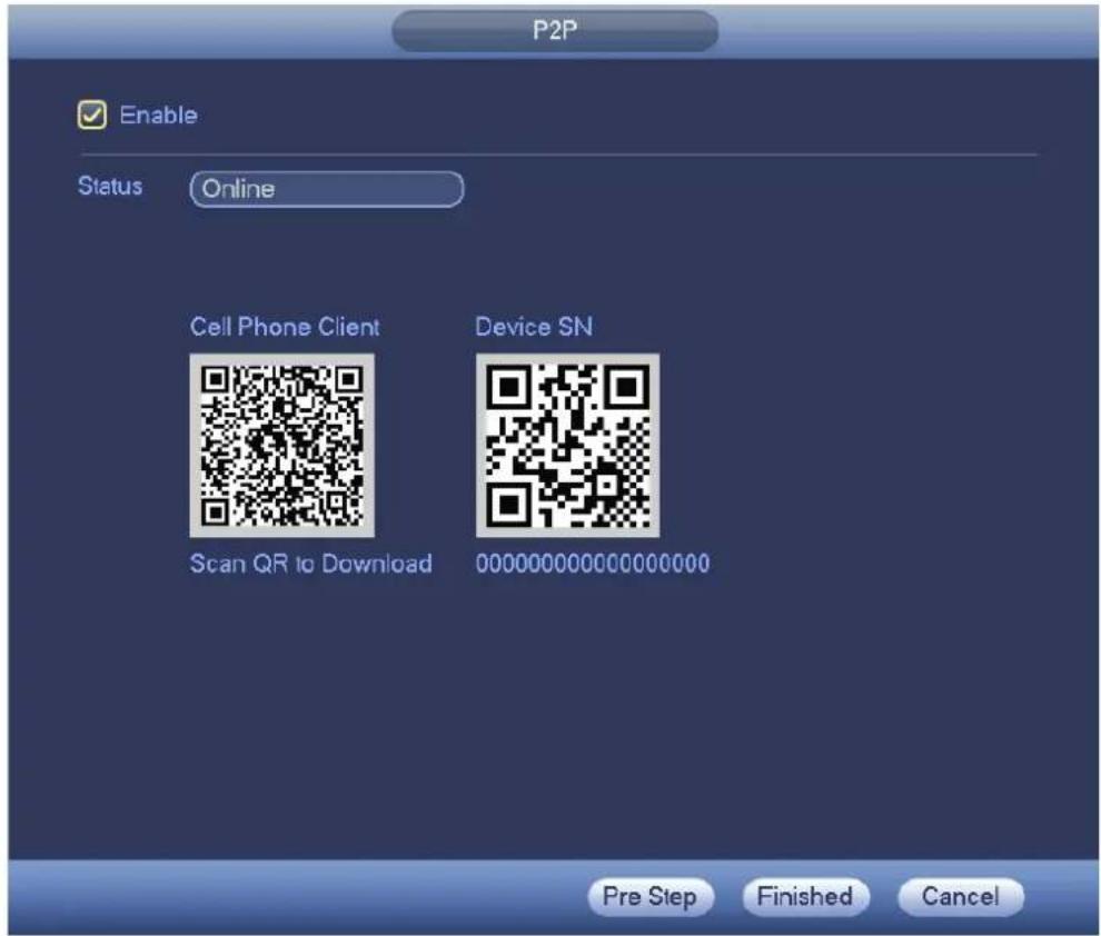
text_image
P2P Enable Status Online Cell Phone Client Device SN Scan QR to Download 000000000000000000 Pre Step Finished CancelFigure 4-9
Click Next button, you can go to remote device interface. See Figure 4-10.
For detailed information, please refer to chapter 4.5.
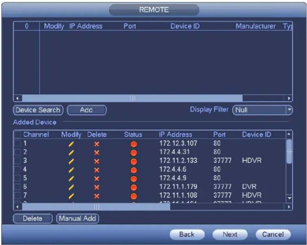
text_image
REMOTE 0 Modify IP Address Port Device ID Manufacturer Typ Device Search Add Display Filter Null Added Device Channel Modify Delete Status IP Address Port Device ID 1 172.12.3.107 80 2 172.4.4.31 80 3 172.11.2.133 37777 HDVR 4 172.4.4.6 80 5 172.4.4.9 80 6 172.11.1.179 37777 DVR 7 172.11.1.108 37777 HDVR 8 172.11.1.164 37777 HDVR Delete Manual Add Back Next CancelFigure 4-10
Click Next button, you can go to Schedule interface. See Figure 4-11.
For detailed information, please refer to chapter 4.10.2.
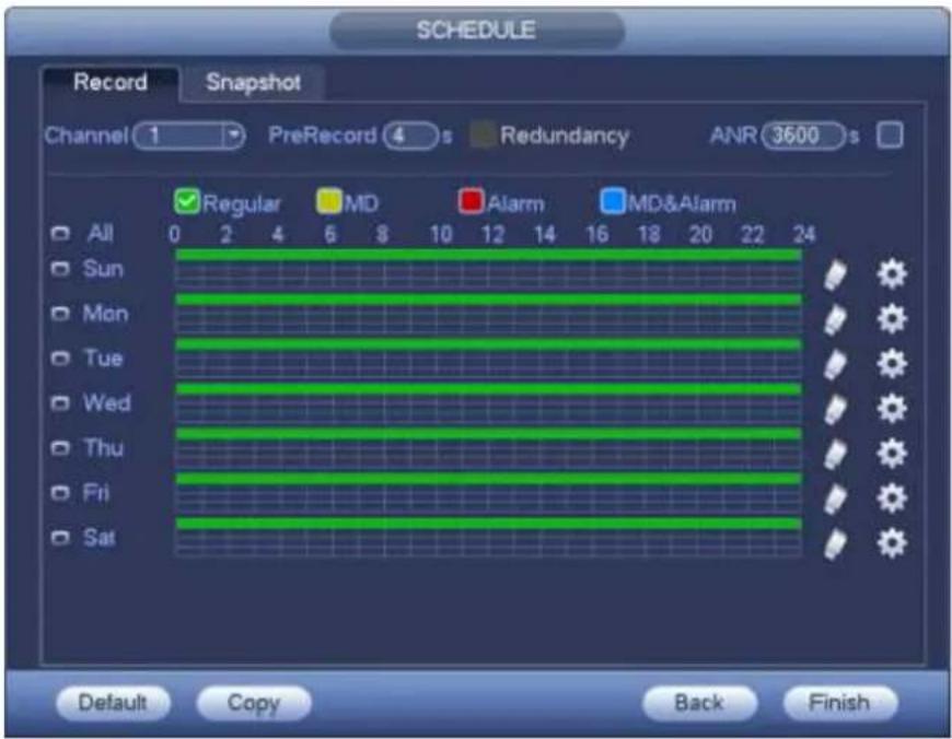
text_image
SCHEDULE Record Snapshot Channel 1 PreRecord 4 s Redundancy ANR 3600 s Regular MD Alarm MD&Alarm All 0 2 4 6 8 10 12 14 16 18 20 22 24 Sun Mon Tue Wed Thu Fri Sat Default Copy Back FinishFigure 4-11
Click Finish button, system pops up a dialogue box. Click the OK button, the startup wizard is complete.
See Figure 4-12.
text_image
Message Startup is finish. OKFigure 4-12
4.4 Navigation Bar
You need to go to the Main menu->Setting->System->General to enable navigation bar function; otherwise you can not see the following interface.
The navigation bar is shown as below. See Figure 4-13.

text_image
1 2 3 4 5 6 7 8 9 10 11 12 13Figure 4-13
4.4.1 Main Menu
Click button to go to the main menu interface.
4.4.2 Dual-screen operation
Important
This function is for some series only.

Click to select screen 2, you can view an interface shown as below. See Figure 4-14. It is a navigation bar for screen 2.

natural_image
Toolbar with icons including a house, cursor, and grid on a blue background (no text or symbols)Figure 4-14
Click any screen split mode; HDMI2 screen can display corresponding screens. Now you can control two screens. See Figure 4-15.

text_image
1-9 8-16 17-25 24-32Figure 4-15
Note
- Screen 2 function is null if tour is in process. Please disable tour function first,
- Right now, the screen 2 operation can only be realized on the navigation bard. The operations on the right-click menu are for screen 1 only.
4.4.3 Output Screen
Select corresponding window-split mode and output channels.
4.4.4 Tour
Click button to enable tour, the icon becomes, you can see the tour is in process.
4.4.5 PTZ
Click, system goes to the PTZ control interface. Please refer to chapter 4.9.2.
4.4.6 Color
Click button, system goes to the color interface. Please refer to chapter 4.7.4.1. Please make sure system is in one-channel mode.
4.4.7 Search
Click button, system goes to search interface. Please refer to chapter 4.11.2
4.4.8 Alarm Status
Click button, system goes to alarm status interface. It is to view device status and channel status. Please refer to chapter 4.17.1.4.
4.4.9 Channel Info
Click button, system goes to the channel information setup interface. It is to view information of the corresponding channel. See Figure 4-16.
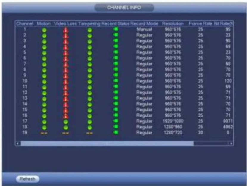
text_image
CHANNEL INFO Channel Motion Video Loss Tampaing Record Status Record Mode Resolution Frame Rate Bit Rate# 1 ● ● ● ● ■ Manual 960*576 25 95 2 ● ● ● ● ■ Regular 960*576 25 33 3 ● ● ● ● ■ Regular 960*576 25 95 4 ● ● ● ● ■ Regular 960*576 25 69 5 ● ● ● ● ■ Regular 960*576 25 33 6 ● ● ● ● ■ Regular 960*576 25 70 7 ● ● ● ● ■ Regular 960*576 25 68 8 ● ● ● ● ■ Regular 960*576 25 70 9 ● ● ● ● ■ Regular 960*576 25 70 10 ● ● ● ● ■ Regular 960*576 25 120 11 ● ● ● ● ■ Regular 960*576 25 69 12 ● ● ● ● ■ Regular 960*576 25 71 13 ● ● ● ● ■ Regular 960*576 25 71 14 ● ● ● ● ■ Regular 960*576 25 70 15 ● ● ● ● ■ Regular 960*576 25 70 16 ● ● ● ● ■ Regular 960*576 25 71 17 ● ● ● ● ■ Regular 1920*1080 25 | 8071 18 ● ● ● ● ■ Regular | 1280*960 | 25 | 4062 19 --- --- --- ■ Regular | 1280*720 | 30 | 0 RefreshFigure 4-16
4.4.10 Remote Device
Click, system goes to the remote device interface. Please refer to chapter 4.5
4.4.11 Network
Click, system goes to the network interface. It is to set network IP address, default gateway and etc. Please refer to chapter 4.14.
4.4.12 HDD Manager
Click a system goes to the HDD manager interface. It is to view and manage HDD information. Please refer to chapter 4.15.1.
4.4.13 USB Manager
Click 📄, system goes to the USB Manager interface. It is to view USB information, backup and update. Please refer to chapter 4.12.1 file backup, chapter 4.12.3 backup log, chapter 4.12.2 import/export, and chapter 4.17.5 upgrade for detailed information.
4.5 Smart Add
When the network camera(s) and the NVR are in the same router or switch, you can use smart add function to add all network cameras to the NVR at the same time.
There are two ways for you to go to the smart add interface.
- From the startup wizard, click Smart add button. See Figure 4-17.
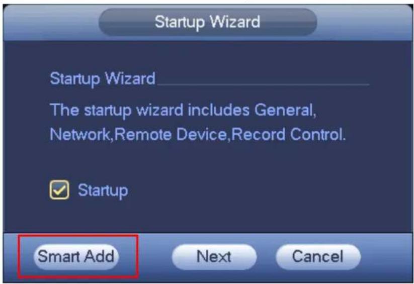
text_image
Startup Wizard Startup Wizard The startup wizard includes General, Network,Remote Device,Record Control. Startup Smart Add Next CancelFigure 4-17
● On the preview interface, right click mouse and then select Smart add. See Figure 4-18.
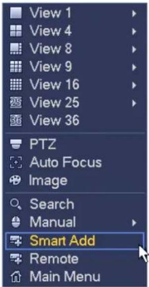
text_image
View 1 View 4 View 8 View 9 View 16 View 25 View 36 PTZ Auto Focus Image Search Manual Smart Add Remote Main MenuFigure 4-18
Now you can go to the smart add interface. See Figure 4-19.
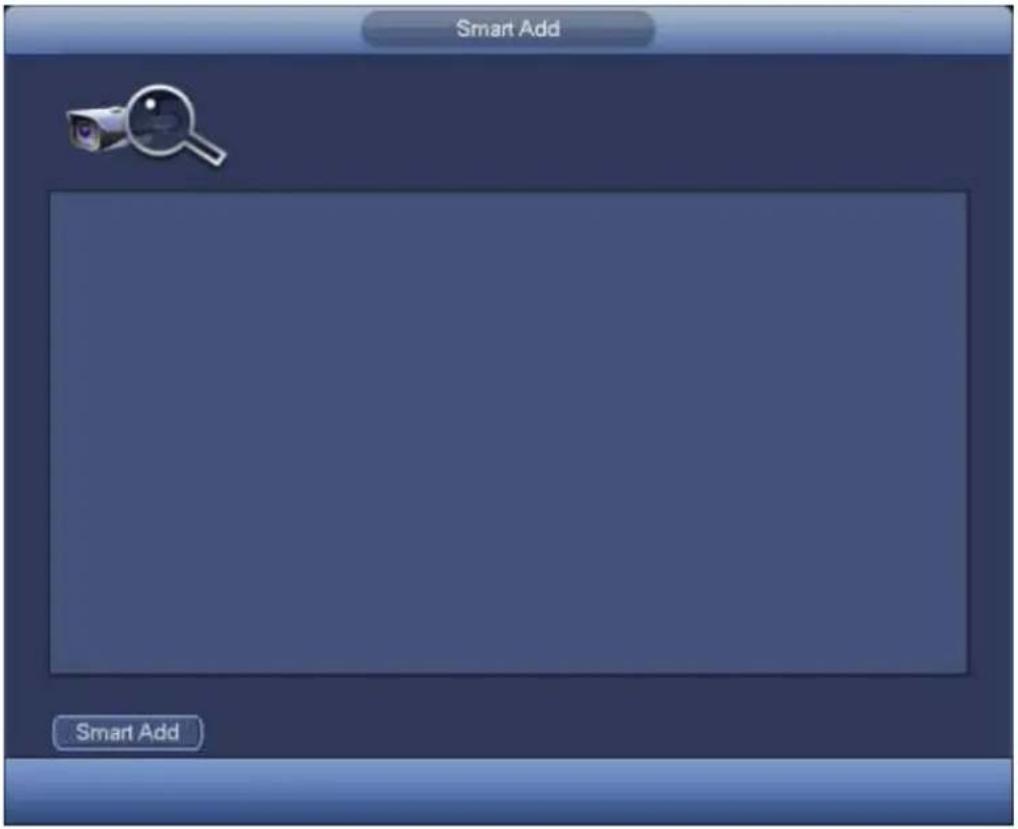
text_image
Smart Add Smart AddFigure 4-19
Click smart add button, you can see device enables DHCP function. See Figure 4-20.
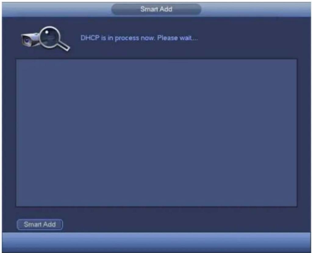
text_image
Smart Add DHCP is in process now. Please wait... Smart AddFigure 4-20
System pops up the following interface for you to confirm IP information if there are several IP segments. See Figure 4-21.
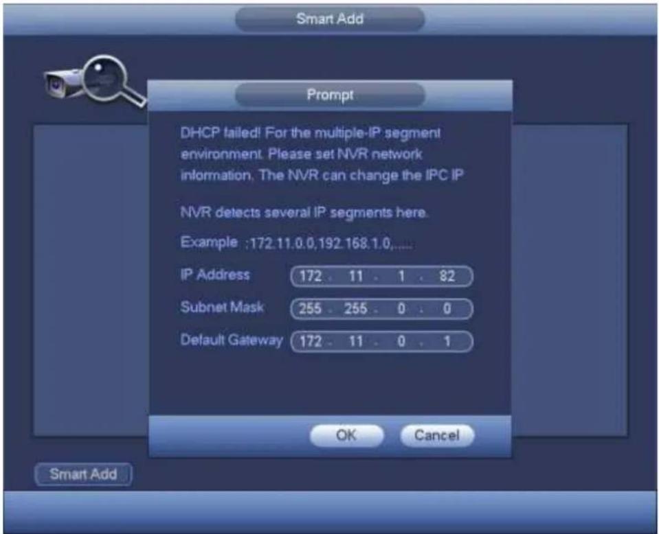
text_image
Smart Add Prompt DHCP failed! For the multiple-IP segment environment. Please set NVR network information. The NVR can change the IPC IP NVR detects several IP segments here. Example :172.11.0.0,192.168.1.0,... IP Address 172 . 11 . 1 . 82 Subnet Mask 255 . 255 . 0 . 0 Default Gateway 172 . 11 . 0 . 1 OK Cancel Smart AddFigure 4-21
Now you can see system is auto adding IPC to the corresponding channels. See Figure 4-22.
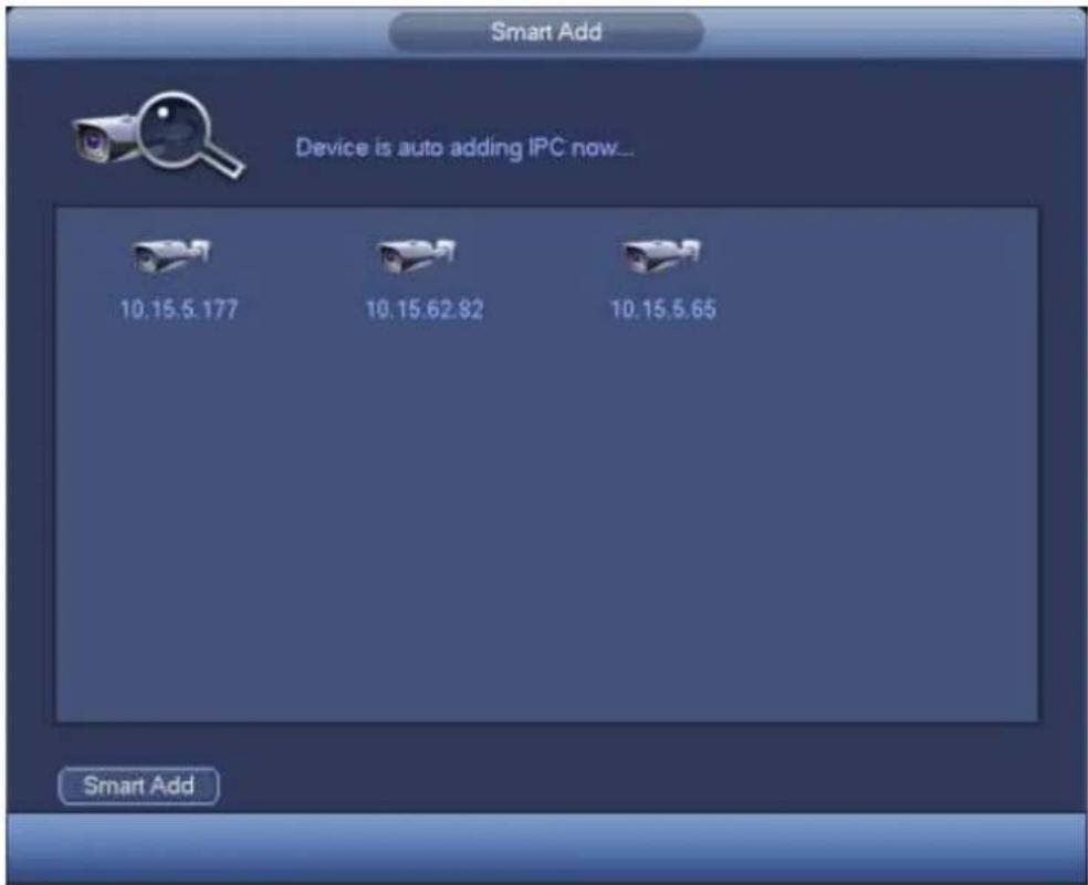
text_image
Smart Add Device is auto adding IPC now... 10.15.5.177 10.15.62.82 10.15.5.65 Smart AddFigure 4-22
You can see the following dialog box after system successfully added network cameras. See Figure 4-23.
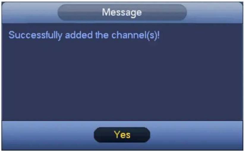
text_image
Message Successfully added the channel(s)! YesFigure 4-23
4.6 Remote Device
4.6.1 Remote Device Connection
From Mani menu->Setting->Remote device or right click mouse on the preview interface and then select remote device item, you can see the following interface. See Figure 4-24.
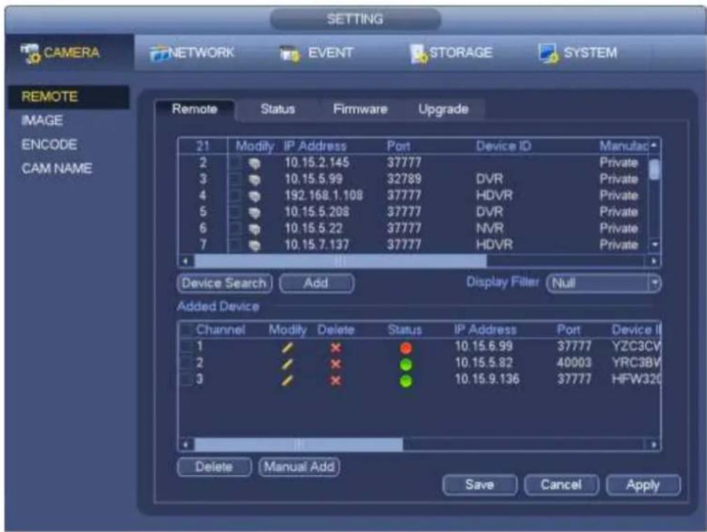
text_image
CAMERA NETWORK EVENT STORAGE SYSTEM REMOTE IMAGE ENCODE CAM NAME Remote Status Firmware Upgrade 21 Modify IP Address Port Device ID Manutac 2 10.15.2.145 37777 Private 3 10.15.5.99 32789 DVR Private 4 192.168.1.108 37777 HDVR Private 5 10.15.5.208 37777 DVR Private 6 10.15.5.22 37777 NVR Private 7 10.15.7.137 37777 HDVR Private Device Search Add Display Filter Null Added Device Channel Modify Delete Status IP Address Port Device ID 1 × ● 10.15.6.99 37777 YZC3CV 2 × ● 10.15.5.82 40003 YRC3BV 3 × ● 10.15.9.136 37777 HFW32G Delete Manual Add Save Cancel ApplyFigure 4-24
Click Device search button, you can view the searched IP addresses at the top pane of the interface. Double click an IP address or check one IP address and then click Add button, you can add current
device to the bottom pane of the interface. System supports batch add function.
Click Manual Add button, you can add a device directly. Here you can set TCP/UPD/auto connection mode. The default setup is TCP. See Figure 4-25.
Important
- Please note the manual add function is for Private, Panasonic, Sony, Dynacolor, Samsung, AXIS, SANYO, Pelco, Arecont, ONVIF, LG, Watchnet, Canon, PSIA, IVC, XUNMEI, and Custom. When the type is the custom, you can just input URL address, user name and password connect to the network camera without considering network camera manufacture. Please contact your network camera manufacturer for the URL address.
- At the bottom of the Figure 4-24, there is remaining bandwidth and total bandwidth information for your reference when you are adding network camera(s).
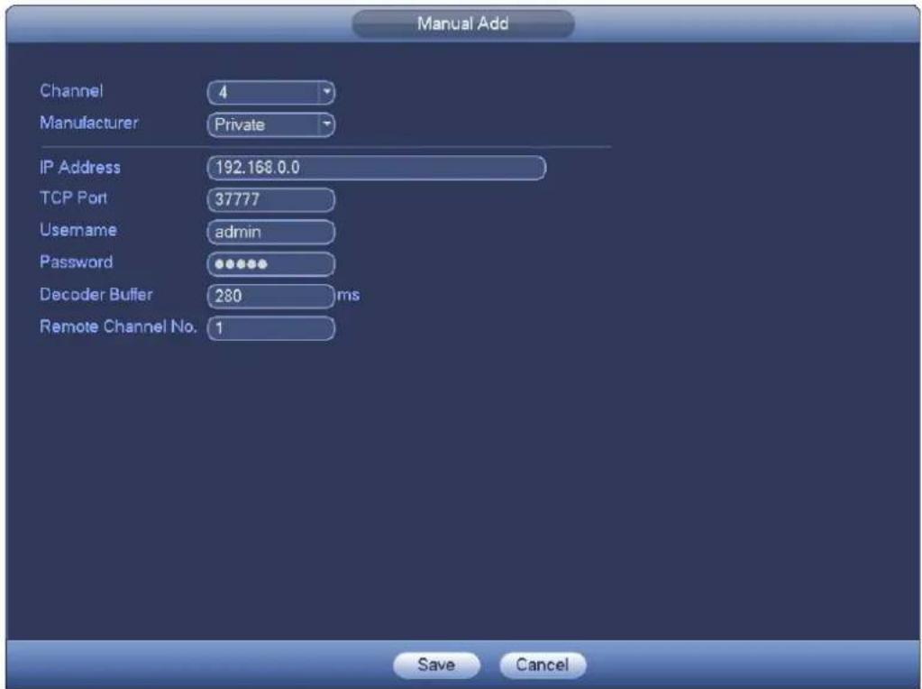
text_image
Manual Add Channel 4 Manufacturer Private IP Address 192.168.0.0 TCP Port 37777 Username admin Password •••••• Decoder Buffer 280 ms Remote Channel No. 1 Save CancelFigure 4-25
4.6.2 Short-Cut Menu
In the preview interface, for the channel of no IPC connection, you can click the icon "+" in the centre of the interface to quickly go to the Remote Device interface. See Figure 4-26.
natural_image
Dark background with a small circular gray object and a white arrow pointing to it, labeled 'CH-1' at the bottom left (no other text or symbols)Figure 4-26
4.6.3 Image
From main menu->setting->camera->image, you can see the image interface is shown as below. See Figure 4-27.
- Channel: Select a channel from the dropdown list.
- Saturation: It is to adjust monitor window saturation. The value ranges from 0 to 100. The default value is 50. The larger the number, the strong the color is. This value has no effect on the general brightness of the whole video. The video color may become too strong if the value is too high. For the grey part of the video, the distortion may occur if the white balance is not accurate. Please note the video may not be attractive if the value is too low. The recommended value ranges from 40 to 60.
- Brightness: It is to adjust monitor window bright. The value ranges from 0 to 100. The default value is 50. The larger the number is, the bright the video is. When you input the value here, the bright section and the dark section of the video will be adjusted accordingly. You can use this function when the whole video is too dark or too bright. Please note the video may become hazy if the value is too high. The recommended value ranges from 40 to 60.
- Contrast: It is to adjust monitor window contrast. The value ranges from 0 to 100. The default value is 50. The larger the number is, the higher the contrast is. You can use this function when the whole video bright is OK but the contrast is not proper. Please note the video may become hazy if the value is too low. If this value is too high, the dark section may lack brightness while the bright section may over exposure. The recommended value ranges from 40 to 60.
- Auto Iris: It is for the device of the auto lens. You can check the box before ON to enable this function. The auto iris may change if the light becomes different. When you disable this function, the iris is at the max. System does not add the auto iris function in the exposure control. This function is on by default.
- Mirror: It is to switch video up and bottom limit. This function is disabled by default.
- Flip: It is to switch video left and right limit. This function is disabled by default.
● BLC: It includes several options: BLC/WDR/HLC/OFF.
✿ BLC: The device auto exposures according to the environments situation so that the darkest area of the video is cleared
WDR: For the WDR scene, this function can lower the high bright section and enhance the brightness of the low bright section. So that you can view these two sections clearly at the same time. The value ranges from 1 to 100. When you switch the camera from no-WDR mode to the WDR mode, system may lose several seconds record video.
HLC: After you enabled HLC function, the device can lower the brightness of the brightest section according to the HLC control level. It can reduce the area of the halo and lower the brightness of the whole video.
✿ OFF: It is to disable the BLC function. Please note this function is disabled by default.
- Profile: It is to set the white balance mode. It has effect on the general hue of the video. This function is on by default. You can select the different scene mode such as auto, sunny, cloudy, home, office, night, disable and etc to adjust the video to the best quality.
Auto: The auto white balance is on. System can auto compensate the color temperature to make sure the vide color is proper.
✿ Sunny: The threshold of the white balance is in the sunny mode.
Night: The threshold of the white balance is in the night mode.
❖ Customized: You can set the gain of the red/blue channel. The value reneges from 0 to 100.
● Day/night. It is to set device color and the B/W mode switch. The default setup is auto.
Color: Device outputs the color video.
Auto: Device auto select to output the color or the B/W video according to the device feature (The general bright of the video or there is IR light or not.)
✿ B/W: The device outputs the black and white video.
Sensor: It is to set when there is peripheral connected IR light.
Please note some non-IR series product support sensor input function.
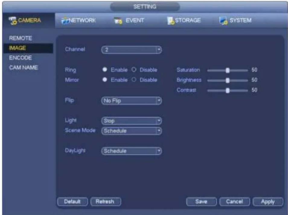
text_image
CAMERA NETWORK EVENT STORAGE SYSTEM REMOTE IMAGE ENCODE CAM NAME Channel 2 Ring Enable Disable Saturation 50 Mirror Enable Disable Brightness 50 Contrast 50 Flip No Flip Light Stop Scene Mode Schedule DayLight Schedule Default Refresh Save Cancel ApplyFigure 4-27
4.6.4 Channel Name
From main menu->Setting->Camera-Channel name, you can see an interface shown as in Figure 4-28. It is to modify channel name. It max supports 31-character.
Please note you can only modify the channel name of the connected network camera.
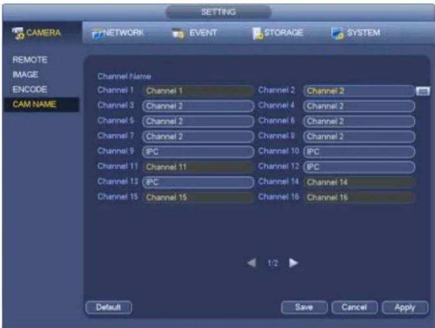
text_image
CAMERA NETWORK EVENT STORAGE SYSTEM REMOTE IMAGE ENCODE CAM NAME Channel Name Channel 1 Channel 1 Channel 2 Channel 2 Channel 3 Channel 2 Channel 4 Channel 2 Channel 5 Channel 2 Channel 6 Channel 2 Channel 7 Channel 2 Channel 8 Channel 2 Channel 9 IPC Channel 10 IPC Channel 11 Channel 11 Channel 12 IPC Channel 13 IPC Channel 14 Channel 14 Channel 15 Channel 15 Channel 16 Channel 16 1/2 Default Save Cancel ApplyFigure 4-28
4.6.5 Upgrade
Note
Right now, the NVR can upgrade the IPC via the USB device or WEB. You can upgrade 8 network cameras of the same model (or the NVR supported) at the same time.
It is to update the network camera.
From main menu->setting->camera->remote, the interface is shown as below. See Figure 4-29.
Click Browse button and then select the upgrade file. Then select a channel (or you can select device type filter to select several devices at the same time.)
Click Begin button to upgrade. You can see the corresponding dialogue once the upgrade is finish.
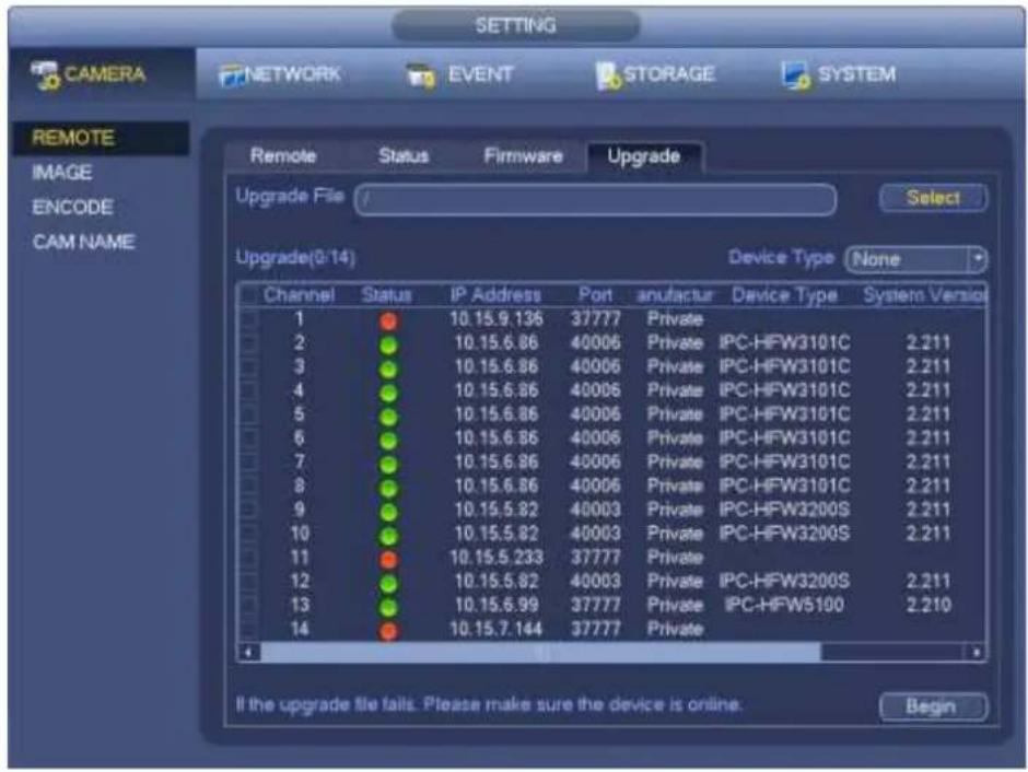
text_image
SETTING CAMERA NETWORK EVENT STORAGE SYSTEM REMOTE IMAGE ENCODE CAM NAME Remote Status Firmware Upgrade Upgrade File Select Upgrade(3:14) Device Type None Channel Status IP Address Port anufactur Device Type System Version 1 ● 10.15.9.136 37777 Private 2 ● 10.15.6.86 40006 Private IPC-HFW3101C 2.211 3 ● 10.15.6.86 40006 Private IPC-HFW3101C 2.211 4 ● 10.15.6.86 40006 Private IPC-HFW3101C 2.211 5 ● 10.15.6.86 40006 Private IPC-HFW3101C 2.211 6 ● 10.15.6.86 40006 Private IPC-HFW3101C 2.211 7 ● 10.15.6.86 40006 Private IPC-HFW3101C 2.211 8 ● 10.15.6.86 40006 Private IPC-HFW3101C 2.211 9 ● 10.15.5.82 40003 Private IPC-HFW3200S 2.211 10 ● 10.15.5.82 40003 Private IPC-HFW3200S 2.211 11 ● 10.15.5.233 37777 Private 12 ● 10.15.5.82 40003 Private IPC-HFW3200S 2.211 13 ● 10.15.6.99 37777 Private IPC-HFW5100 2.210 14 ● 10.15.7.144 37777 Private If the upgrade file fails. Please make sure the device is online. BeginFigure 4-29
4.6.6 UPNP
Important
Do not connect the switch to the PoE port, otherwise the connection may fail!
Please connect the IPC to the PoE port of the device rear panel (Figure 4-30), system can auto connect to the network camera. Please note the following figure is for reference only.

text_image
RS232 VGA HDMI X11NFigure 4-30
4.6.7 Built-in Switch Setup
The built-in switch function is for product of PoE port.
From Main menu->Setting->Network->Switch, you can set switch IP address, subnet mask, gateway and etc. See Figure 4-31.
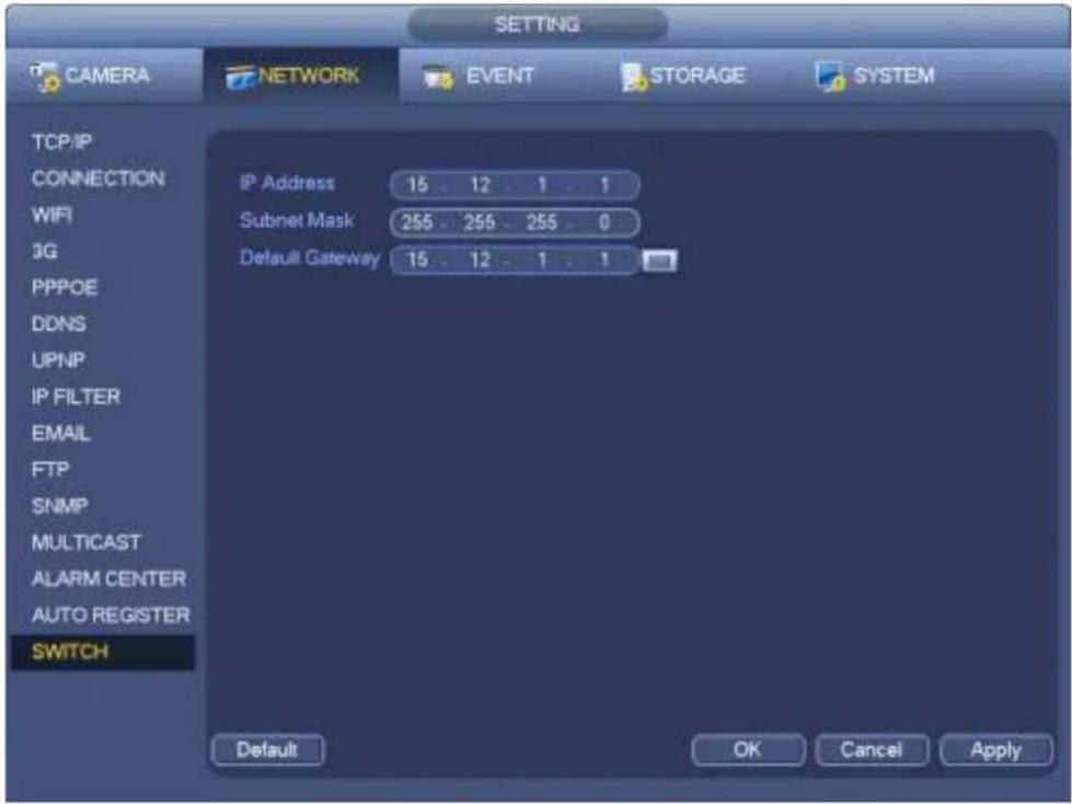
text_image
SETTING CAMERA NETWORK EVENT STORAGE SYSTEM TCP/IP CONNECTION IP Address 15 12 1 1 WiFi Subnet Mask 255 255 255 0 3G Default Gateway 15 12 1 1 PPPOE DDNS UPNP IP FILTER EMAIL FTP SNMP MULTICAST ALARM CENTER AUTO REGISTER SWITCH Default OK Cancel ApplyFigure 4-31
4.7 Preview
After device booted up, the system is in multiple-channel display mode. See Figure 4-32. Please note the displayed window amount may vary. The following figure is for reference only. Please refer to chapter 1.3 Specifications for the window-amount your product supported.

natural_image
Grid of 16 diverse outdoor scenes including houses, a fire, dining table, and cityscape (no visible text or symbols)Figure 4-32
4.7.1 Preview
If you want to change system date and time, you can refer to general settings (Main Menu->Setting->System->General). If you want to modify the channel name, please refer to the display settings (Main Menu->Camera->CAM name) Please refer to the following sheet for detailed information.
| 1 | Recording status | 3 | Video loss | ||
| 2 | Motion detection | 4 | Camera lock |
Tips
- Preview drag: If you want to change position of channel 1 and channel 2 when you are previewing, you can left click mouse in the channel 1 and then drag to channel 2, release mouse you can switch channel 1 and channel 2 positions.
- Use mouse middle button to control window split: You can use mouse middle button to switch window split amount.
4.7.2 Preview control interface
Move you mouse to the top centre of the video of current channel, you can see system pops up the preview control interface. See Figure 4-33. If your mouse stays in this area for more than 6 seconds and has no operation, the control bar automatically hides.
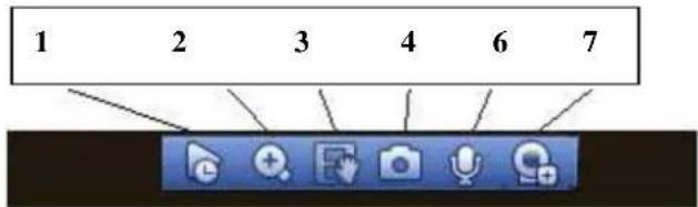
text_image
1 2 3 4 6 7Figure 4-33 Digital Channel
1) Realtime playback
It is to playback the previous 5-60 minutes record of current channel.
Please go to the Main menu->Setting->->System->General to set real-time playback time.
System may pop up a dialogue box if there is no such record in current channel.
2) Digital zoom
It is to zoom in specified zone of current channel. It supports zoom in function of multiple-channel.
Click button , the button is shown as .
There are two ways for you to zoom in.
- Drag the mouse to select a zone, you can view an interface show as Figure 4-34.
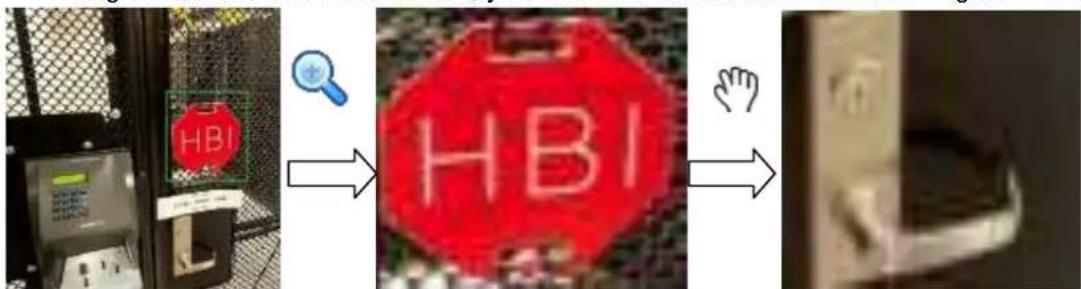
text_image
HBI HBIFigure 4-34
- Put the middle button at the centre of the zone you want to zoom in, and move the mouse, you can view an interface shown as in Figure 4-35.
text_image
HB HBIFigure 4-35
Right click mouse to cancel zoom and go back to the original interface.
3) Manual record function
It is to backup the video of current channel to the USB device. System can not backup the video of multiple-channel at the same time.
Click button, system begins recording. Click it again, system stops recording. You can find the record file on the flash disk.
4) Manual Snapshot
Click to snapshot 1-5 times. The snapshot file is saved on the USB device or HDD. You can go to the Search interface (chapter 4.11) to view.
5) Bidirectional talk
If the connected front-end device supports bidirectional talk function, you can click this button. Click
button 📋 to start bidirectional talk function the icon now is shown as 🔔. Now the rest bidirectional talk buttons of digital channel becomes null too.
Click 🖼 again, you can cancel bidirectional talk and the bidirectional talk buttons of other digital channels become as 🖼
6) Remote device
Shortcut menu. Click it to go to the remote device interface to add/delete remote device or view its corresponding information. Please refer to chapter4.6.2 for detailed information.
4.7.3 Right Click Menu
After you logged in the device, right click mouse, you can see the short cut menu. Please see Figure 4-36.
● Window split mode: You can select window amount and then select channels.
● PTZ: Click it to go to PTZ interface.
- Auto focus: It is to set auto focus function. Please make sure the connected network camera supports this function.
● Color setting: Set video corresponding information.
- Search: Click it to go to Search interface to search and playback a record file.
● Record control: Enable/disable record channel.
● Alarm output: It is to set alarm output mode.
- Remote device: Search and add a remote device.
● Alarm output: Generate alarm output signal manually. - Main menu: Go to system main menu interface.
Tips:
Right click mouse to go back to the previous interface.
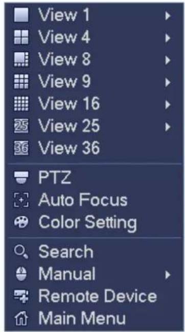
text_image
View 1 View 4 View 8 View 9 View 16 View 25 View 36 PTZ Auto Focus Color Setting Search Manual Remote Device Main MenuFigure 4-36
4.7.4 Preview Display Effect Setup
4.7.4.1 Video Color
Here you can set hue, brightness, contrast, saturation, gain, white level, color mode and etc. See Figure 4-37.
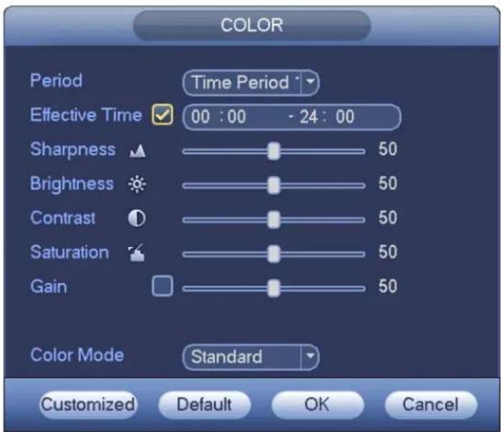
text_image
COLOR Period Time Period Effective Time 00:00 - 24:00 Sharpness 50 Brightness 50 Contrast 50 Saturation 50 Gain 50 Color Mode Standard Customized Default OK CancelFigure 4-37
Please refer to the following sheet for detailed information.
| Item | Note |
| Period | There are two periods in one day. You can set different sharpness, brightness, and contrast setup for different periods. |
| Effective Time | Check the box here to enable this function and then set period time. |
| Sharpness | The value here is to adjust the edge of the video. The value ranges from 0 to 100. The larger the value is, the clear the edge is and vice versa. Please note there is noise if the value here is too high. The default value is 50 and the recommended value ranges from 40 to 60. |
| Brightness | It is to adjust monitor window bright. The value ranges from 0 to 100. The default value is 50.The larger the number, the bright the video is. When you input the value here, the bright section and the dark section of the video will be adjusted accordingly. You can use this function when the whole video is too dark or too bright. Please note the video may become hazy if the value is too high. The recommended value ranges from 40 to 60. |
| Contrast | It is to adjust monitor window contrast. The value ranges from 0 to 100. The default value is 50.The larger the number, the higher the contrast is. You can use this function when the whole video bright is OK but the contrast is not proper. Please note the video may become hazy if the value is too low. If this value is too high, the dark section may lack brightness while the bright section may over exposure .The recommended value ranges from 40 to 60. |
| Saturation | It is to adjust monitor window saturation. The value ranges from 0 to 100. The default value is 50.The larger the number, the strong the color is. This value has no effect on the general brightness of the whole video. The video color may become too strong if the value is too high. For the grey part of the video, the distortion may occur if the white balance is not accurate. Please note the video may not be attractive if the value is too low. The recommended value ranges from 40 to 60. |
| Gain | The gain adjust is to set the gain value. The default value may vary due to different device models. The smaller the value, the low the noise. But the brightness is also too low in the dark environments. It can enhance the video brightness if the value is high. But the video noise may become too clear. |
| Color mode | It includes several modes such as standard, color, bright, gentle. Select a color mode, the sharpness, brightness, contrast and etc can automatically switch to corresponding setup. |
4.7.4.2 Display
From Main Menu->Setting->System->Display, you can go to the following interface. See Figure 4-38. Here you can set menu and video preview effect. All you operation here does not affect the record file and playback effect.
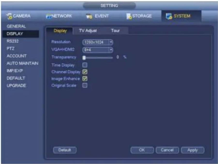
text_image
SETTING CAMERA NETWORK EVENT STORAGE SYSTEM GENERAL DISPLAY RS232 PTZ ACCOUNT AUTO MAINTAIN IMP/EXP DEFAULT UPGRADE Display TV Adjust Tour Resolution 1200x1024 VGA+HDMI2 8+4 Transparency 0 % Time Display Channel Display Image Enhance Original Scale Default OK Cancel Apply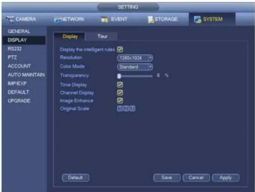
text_image
CAMERA NETWORK EVENT STORAGE SYSTEM GENERAL DISPLAY RS232 PTZ ACCOUNT AUTO MAINTAIN IMPEXP DEFAULT UPGRADE Display Tour Display the intelligent rules Resolution 1280x1024 Color Mode Standard Transparency 0 % Time Display ✓ Channel Display ✓ Image Enhance ✓ Original Scale 0.2.3 Default Save Cancel ApplyFigure 4-38
Now you can set corresponding information.
- Display the intelligent rule(s): Check the box to enable IVS function, system can display IVS rule on the preview interface. Please note this function is for some series only.
-
Resolution: There are five options: 1280×1024 (Default), 1280×720, 1920×1080, 1024×768 and 3840×2160. Please note the system needs to reboot to activate current setup. Please note 3840×2160 is for some series only.
-
VGA+HDMI2: It is for dual-screen operation. Please select from the dropdown list according to your actual situation. Click Apply button, system needs to restart to activate new setup. For example, 32+4 means for VGA, system max supports 32-window split and for HDMI2, system max supports 4-window split. Please note this function is for some series only.
● Color mode: Please select from the dropdown list. It is to set video color mode. - Transparency: Here is for you to adjust menu transparency. The higher the value is, the better transparent the menu is.
- Channel name: Here is for you to modify channel name. System max support 25-digit (The value may vary due to different series). Please note all your modification here only applies to NVR local end. You need to open web or client end to refresh channel name.
● Time display: You can select to display time or not when system is playback. - Channel display: You can select to channel name or not when system is playback.
- Image enhance: Check the box; you can optimize the margin of the preview video.
- Original scale: Check the box here to select a corresponding channel; it can restore video original scale.
Click OK button to save current setup.
4.7.4.3 TV adjust
Note
Some series product supports TV adjust function. This function is disabled by default.
From Main Menu->Setting->System->Display->TV adjust; you can go to the following interface. See Figure 4-38. Here you can set margins and brightness.
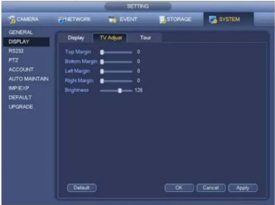
text_image
SETTING CAMERA NETWORK EVENT STORAGE SYSTEM GENERAL DISPLAY RS232 PTZ ACCOUNT AUTO MAINTAIN IMP/EXP DEFAULT UPGRADE Display TV Adjust Tour Top Margin 0 Bottom Margin 0 Left Margin 0 Right Margin 0 Brightness 128 Default OK Cancel ApplyFigure 4-39
4.7.5 Preview Tour Parameters
Set preview display mode, channel display sequence and tour setup.
- Set preview display mode: On the preview interface, right click mouse, you can view right-click menu. Now you can select preview window amount and channel.
- Set channel display mode: On the preview interface, if you want to change channel 1 and channel 16 position, please right click channel 1 video window and then drag to the channel 16 video window, release button, you can change channel 1 and channel 16 position.
- Tour setup: Here you can set preview window channel display mode and interval. Please follow the steps listed below.
From Main menu->Setting->System->Display->Tour, you can see an interface shown as in Figure 4-40.
Here you can set tour parameter.
- Enable tour: Check the box here to enable tour function. The general tour supports all types of window split mode.
- Interval: Input proper interval value here. The value ranges from 1-120 seconds.
- Motion tour type: System support 1/8-window tour. Please note you need to go to the main menu->Setting->Event->Video detect->Motion detect to enable tour function.
- Alarm tour type: System support 1/8-window tour. Please note you need to go to the main menu->Setting->Event->Alarm to enable tour function.
● Window split: It is to set window split mode.
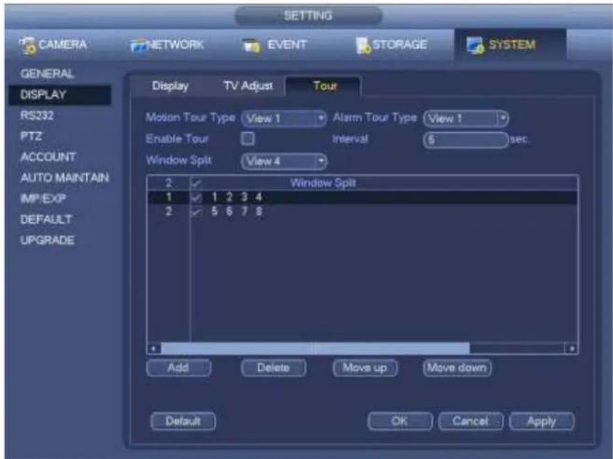
text_image
SETTING CAMERA NETWORK EVENT STORAGE SYSTEM GENERAL DISPLAY RS232 PTZ ACCOUNT AUTO MAINTAIN IMP EXP DEFAULT UPGRADE Display TV Adjust Tour Motion Tour Type View 1 Alarm Tour Type View 1 Enable Tour Interval 5 sec. Window Split View 4 2 Window Split 1 1 2 3 4 2 5 6 7 8 Add Delete Move up Move down Default OK Cancel ApplyFigure 4-40
Tips
On the navigation bar, click / to enable/disable tour.
Click Save button to save current setup.
4.8 Fish eye (Optional)
Please note this function is for some series only.
4.8.1 Fish eye de-warp during preview interface
On the preview interface, select fish eye channel and then right click mouse, you can select fish eye. See
Figure 4-41.
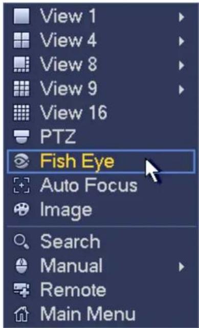
text_image
View 1 View 4 View 8 View 9 View 16 PTZ Fish Eye Auto Focus Image Search Manual Remote Main MenuFigure 4-41
Now you can see an interface shown as in Figure 4-42. You can set fish eye installation mode and display mode.
Note:
- For the non-fish eye channel, system pops up dialogue box to remind you it is not a fish eye channel and does not support de-warp function.
- If system resources are insufficient, system pops up the corresponding dialogue box too.
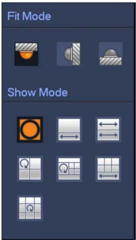
text_image
Fit Mode Show ModeFigure 4-42
There are three installation modes: ceiling mount/wall mount/ground mount. The different installations modes have different de-warp modes.
Please refer to the following sheet for detailed information.
| Installation modes | Icon | Note | |
 | (Ceiling mount) |  | 360° panorama original view |
 | 1 de-warp window+1 panorama stretching | ||
 | (Ground mount) |  | 2 panorama stretching view |
 | 1 360° panorama view+3 de-warp windows | ||
 | 1 360° panorama view+4 de-warp windows | ||
 | 4 de-warp windows+1 panorama stretching | ||
 | 1 360° panorama view+8 de-warp windows | ||
 | (Wall mount) |  | 360° panorama original view |
 | Panorama stretching | ||
 | 1 panorama unfolding view+3 de-warp windows | ||
 | 1 panorama unfolding view +4 de warp windows | ||
 | 1 panorama unfolding view +8 de warp windows | ||
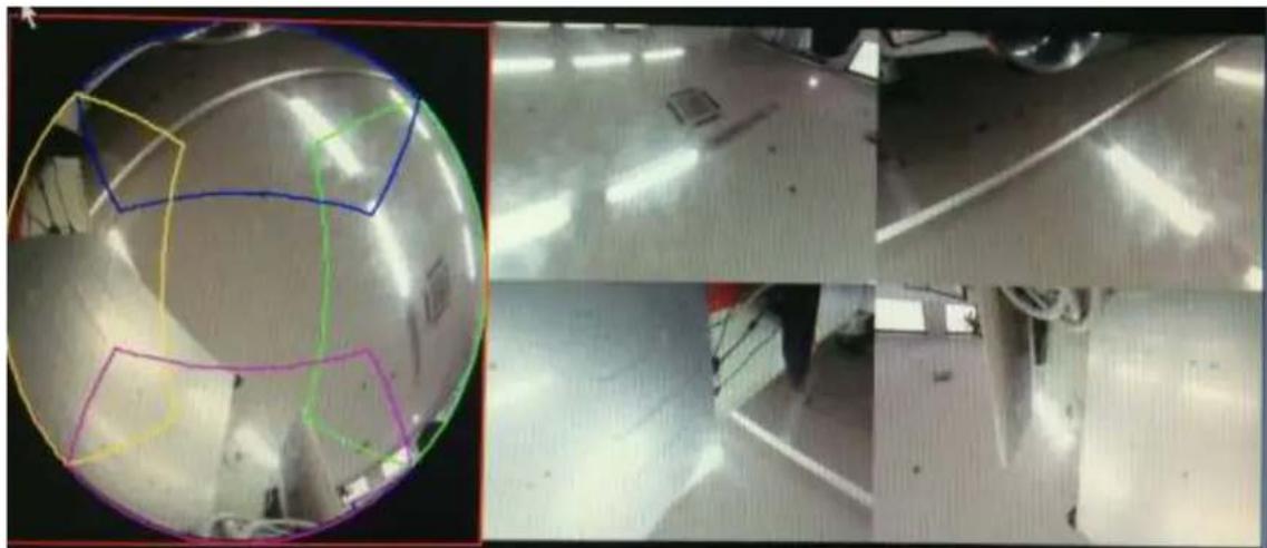
natural_image
Four-panel image showing a spherical object with colored outlines and a metallic floor, alongside three close-up photos of industrial equipment (no visible text or symbols)Figure 4-43
In Figure 4-43, you can adjust the color pane on the left pane or use your mouse to change the position of the small images on the right pane to realize fish eye de-warp.
4.8.2 Fish eye de-warp during playback
On the main menu, click search button.
Select 1-window playback mode and corresponding fish eye channel, click to play.
Right click the , you can go to the de-warp playback interface. For detailed information, please refer to chapter 4.8.1.
4.9 PTZ
Note:
Before you control the PTZ, please make sure the PTZ decoder and the NVR network connection is OK and the corresponding settings are right.
4.9.1 PTZ Settings
Cable Connection
Please follow the procedures below to go on cable connection
- Connect the dome RS485 port to NVR RS485 port.
- Connect dome video output cable to NVR video input port.
- Connect power adapter to the dome.
In the main menu, from Setting->System->PTZ, you can see an interface is shown as in Figure 4-44.
Here you can set the following items:
● Channel: Select the current camera channel.
- PTZ type: There are two types: local/remote. Please select local mode if you are connect RS485 cable to connect to the Speed dome (PTZ). Please select remote mode if you are connecting to the network PTZ camera.
- Protocol: Select corresponding PTZ protocol(such as PELCOD)
- Address: Default address is 1.
● Baud rate: Select corresponding baud rate. Default value is 9600.
● Data bit: Select corresponding data bits. Default value is 8.
- Stop bit: Select corresponding stop bits. Default value is 1.
● Parity: There are three options: odd/even/none. Default setup is none.
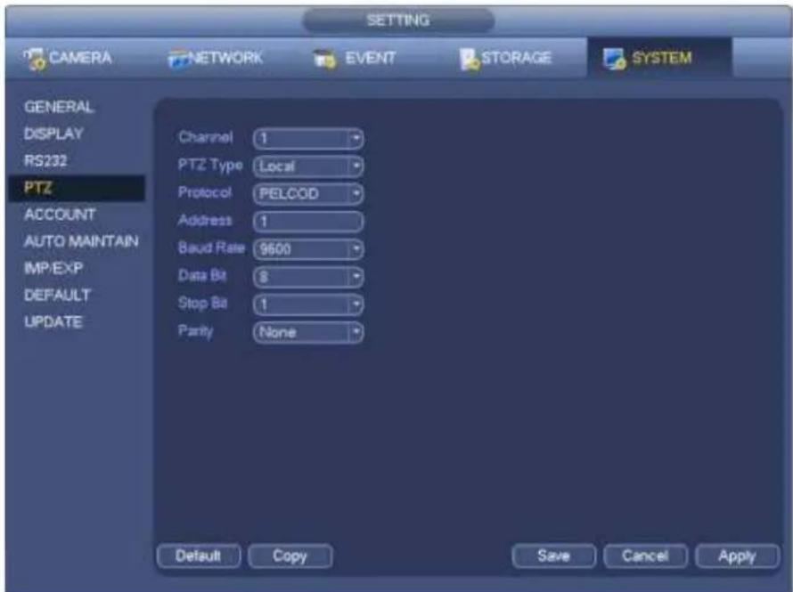
text_image
SETTING CAMERA NETWORK EVENT STORAGE SYSTEM GENERAL DISPLAY RS232 PTZ ACCOUNT AUTO MAINTAIN IMP/EXP DEFAULT UPDATE Channel 1 PTZ Type Local Protocol PELCOD Address 1 Baud Rate 9600 Data Bit $ Stop Bit 1 Parity None Default Copy Save Cancel ApplyFigure 4-44
If you are connecting to network PTZ, the PTZ type shall be remote. See Figure 4-45.
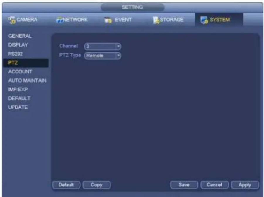
text_image
SETTING CAMERA NETWORK EVENT STORAGE SYSTEM GENERAL DISPLAY RS232 PTZ ACCOUNT AUTO MAINTAIN IMPEXP DEFAULT UPDATE Channel 3 PTZ Type Remote Default Copy Save Cancel ApplyFigure 4-45
4.9.2 PTZ Control
After completing all the setting please click save button. Right click mouse (click "Fn" Button in the front panel or click "Fn" key in the remote control). The interface is shown as in Figure 4-46. Please note you can only go to the PTZ control interface when you are in 1-window display mode.
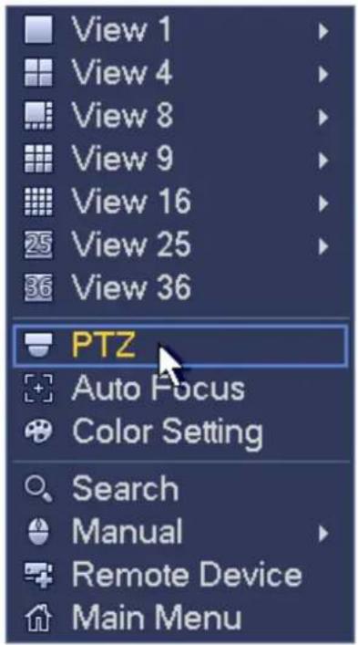
text_image
View 1 View 4 View 8 View 9 View 16 25 View 25 36 View 36 PTZ Auto Focus Color Setting Search Manual Remote Device Main MenuFigure 4-46
The PTZ setup is shown as in See Figure 4-47.
Please note the commend name is grey once device does not support this function.
The PTZ operation is only valid in one-window mode.
Here you can control PTZ direction, speed, zoom, focus, iris, preset, tour, scan, pattern aux function, light and wiper, rotation and etc.
Speed is to control PTZ movement speed. The value ranges from 1 to 8. The speed 8 is faster than speed 1. You can use the remote control to click the small keyboard to set.
You can click - and + of the zoom, focus and iris to zoom in/out, definition and brightness.
The PTZ rotation supports 8 directions. If you are using direction buttons on the front panel, there are only four directions: up/down/left/right.
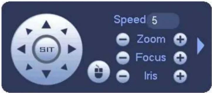
text_image
SIT Speed 5 Zoom + Focus + Iris +Figure 4-47
In the middle of the eight direction arrows, there is a 3D intelligent positioning key. See Figure 4-48. Please make sure your protocol supports this function and you need to use mouse to control. Click this key, system goes back to the single screen mode. Drag the mouse in the screen to adjust section size. The dragged zone supports 4X to 16X speeds. It can realize PTZ automatically. The smaller
zone you dragged, the higher the speed.

Figure 4-48
| Name | Function key | function | Shortcut key | Function key | function | Shortcut key |
| Zoom |  | Near |  | Far | ||
| Focus |  | Near | |◀ |  | Far | ▶| |
| Iris |  | close | II◀ |  | Open | ▶II |
In Figure 4-47, click to open the menu, you can set preset, tour, pattern, scan and etc. See Figure 4-49.
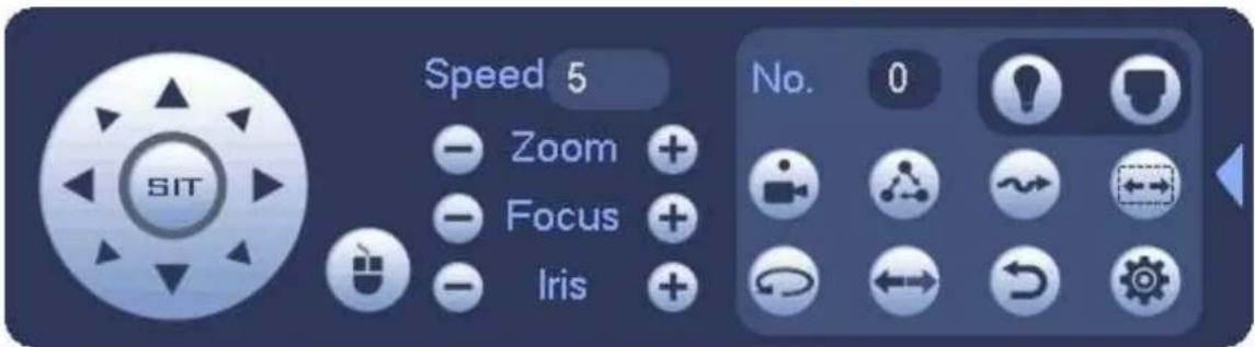
text_image
SIT Speed 5 Zoom + Focus + Iris No. 0Figure 4-49
Please refer to the following sheet for detailed information.
Please note the above interface may vary due to different protocols. The button is grey and can not be selected once the current function is null.
Right click mouse or click the ESC button at the front panel to go back to the Figure 4-47.
| Icon | Function | Icon | Function |
 | Preset | Flip | |
 | Tour | Reset | |
 | Pattern | Aux | |
 | Scan | Aux on-off button | |
 | Rotate | Go to menu |
4.9.2.1 PTZ Function Setup
Click, you can go to the following interface to set preset, tour, pattern, and scan. See Figure 4-50.
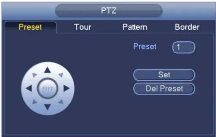
text_image
PTZ Preset Tour Pattern Border Preset 1 Set Del PresetFigure 4-50
Preset Setup
In Figure 4-50, click preset button and use eight direction arrows to adjust camera to the proper position.
The interface is shown as in Figure 4-51.
Click Set button and then input preset number.
Click Set button to save current preset.
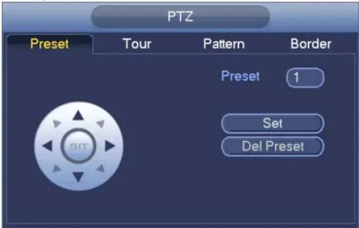
text_image
PTZ Preset Tour Pattern Border Preset 1 Set Del PresetFigure 4-51
Tour Setup
In Figure 4-50, click tour button.
Input tour value and preset No. Click Add preset button to add current preset to the tour. See Figure 4-52.
Tips
Repeat the above steps to add more presets to the tour. Click Del preset button to remove it from the tour.
Please note some protocols do not support delete preset function.
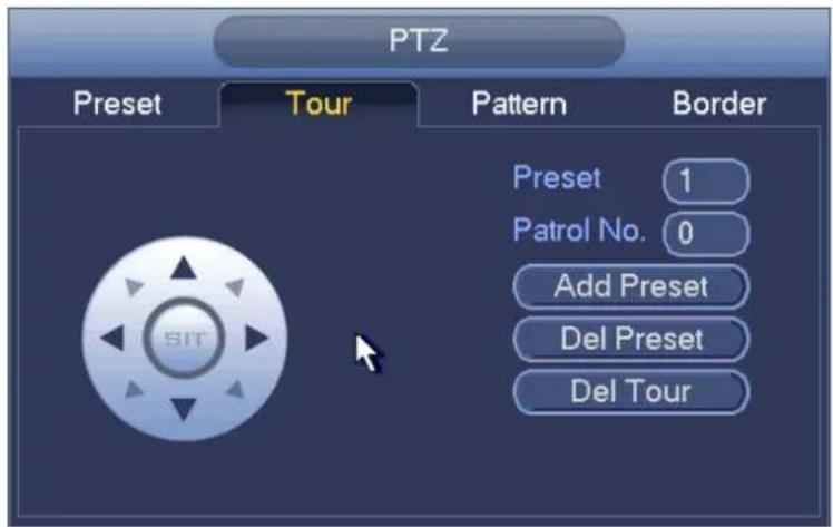
text_image
PTZ Preset Tour Pattern Border Preset 1 Patrol No. 0 Add Preset Del Preset Del TourFigure 4-52
Pattern Setup
In Figure 4-50, click Pattern button and input pattern number.
Click Begin button to start direction operation. Or you can go back to Figure 4-47 to operate zoom/focus/iris/direction operation.
In Figure 4-50, click End button.
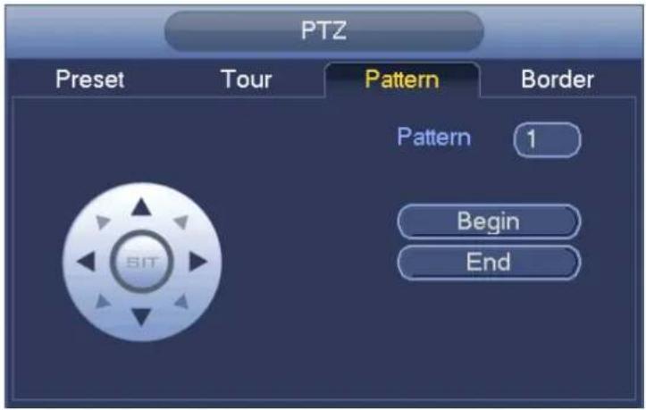
text_image
PTZ Preset Tour Pattern Border Pattern 1 Begin EndFigure 4-53
Scan Setup
In Figure 4-50, click Scan button.
Use direction buttons to set camera left limit and then click Left button.
Use direction buttons to set camera right limit and then click Right button. Now the scan setup process is complete.
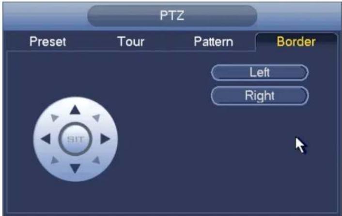
text_image
PTZ Preset Tour Pattern Border Left Right SITFigure 4-54
4.9.2.2 Call PTZ Function
Call Preset
In Figure 4-49, input preset value and then click

to call a preset. Click

again to stop call.
Call Pattern
In Figure 4-49, input pattern value and then click call.

to call a pattern. Click
again to

Call Tour
In Figure 4-49, input tour value and then click

to call a tour. Click again

to stop call.
Call Scan
In Figure 4-49, input Scan value and then click

to call a tour. Click again

to stop call.
Rotate
In Figure 4-49, click to enable the camera to rotate.
System supports preset, tour, pattern, scan, rotate, light and etc function.
Note:
- Preset, tour and pattern all need the value to be the control parameters. You can define it as you require.
- You need to refer to your camera user's manual for Aux definition. In some cases, it can be used for special process.
Aux

Click, system goes to the following interface. The options here are defined by the protocol. The aux number is corresponding to the aux on-off button of the decoder. See Figure 4-55.
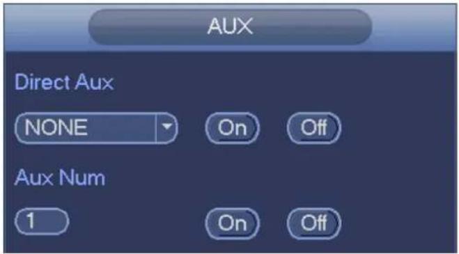
text_image
AUX Direct Aux NONE On Off Aux Num 1 On OffFigure 4-55
4.10 Record and Snapshot
The record/snapshot priority is: Alarm->Motion detect->Schedule.
4.10.1 Encode
4.10.1.1 Encode
Encode setting is to set IPC encode mode, resolution, bit stream type and etc
From Main menu->Setting->System->Encode, you can see the following interface. See Figure 4-56.
- Channel: Select the channel you want.
- Type: Please select from the dropdown list. There are three options: regular/motion detect/alarm. You can set the various encode parameters for different record types.
- Compression: System supports H.264, MPEG4, MJPEG and etc.
- Resolution: The mainstream resolution type is IPC's encoding config. Generally there is D1/720P/1080P. For NVR42-4K, NVR42-8P-4K series product, the main stream supports 2048×1536(3M), 1920×1080(1080P), 1280×1024(S×GA), 1280×960(1.3M), 1280×720(720P), 704×576(D1) and the sub stream supports 704×576(D1), 352×288(CIF).
- Frame rate: It ranges from 1f/s to 25f/s in NTSC mode and 1f/s to 30f/s in PAL mode.
● Bit rate type: System supports two types: CBR and VBR. In VBR mode, you can set video quality.
● Quality: There are six levels ranging from 1 to 6. The sixth level has the highest image quality.
- Video/audio: You can enable or disable the video/audio. Please note, once you enable audio function for one channel, system may enable audio function of the rest channels by default.
- Copy: After you complete the setup, you can click Copy button to copy current setup to other channel(s). You can see an interface is shown as in Figure 4-59. You can see current channel number is grey. Please check the number to select the channel or you can check the box ALL. Please click the OK button in Figure 4-59 and Figure 4-57 respectively to complete the setup. Please note, once you check the All box, you set same encode setup for all channels. Audio/video enable box, overlay button and the copy button is shield.
Please highlight icon to select the corresponding function.
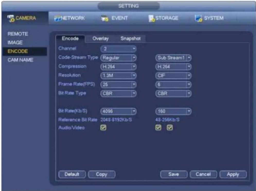
text_image
CAMERA NETWORK EVENT STORAGE SYSTEM REMOTE IMAGE ENCODE CAM NAME Encode Overlay Snapshot Channel 2 Code-Stream Type Regular Sub Stream1 Compression H.264 H.264 Resolution 1.3M CIF Frame Rate(FPS) 25 5 Bit Rate Type CBR CBR Bit Rate(Kb/S) 4096 150 Reference Bit Rate 2048-8192Kb/S 48-256Kb/S Audio/Video Default Copy Save Cancel ApplyFigure 4-56
4.10.1.2 Overlay
Click overlay button, you can see an interface is shown in Figure 4-57.
- Cover area: Here is for you to cover area section. You can drag you mouse to set proper section size. In one channel video, system max supports 4 zones in one channel. You can set with Fn button or direction buttons.
- Preview/monitor: The cover area has two types. Preview and Monitor. Preview means the privacy mask zone can not be viewed by user when system is in preview status. Monitor means the privacy mask zone can not be view by the user when system is in monitor status.
- Time display: You can select system displays time or not when you playback. Please click set button and then drag the title to the corresponding position in the screen.
- Channel display: You can select system displays channel number or not when you playback. Please click set button and then drag the title to the corresponding position in the screen.
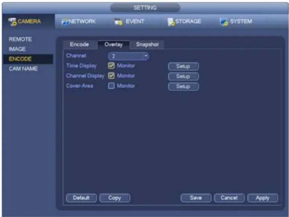
text_image
CAMERA NETWORK EVENT STORAGE SYSTEM REMOTE IMAGE ENCODE CAM NAME Encode Overlay Snapshot Channel 2 Time Display Monitor Setup Channel Display Monitor Setup Cover-Area Monitor Setup Default Copy Save Cancel ApplyFigure 4-57
4.10.1.3 Snapshot
Here you can set snapshot mode, picture size, quality and frequency. See Figure 4-58.
- Snapshot mode: There are two modes: regular and trigger. If you set regular mode, you need to set snapshot frequency. If you set trigger snapshot, you need to set snapshot activation operation.
- Image size: Here you can set snapshot picture size.
- Image quality: Here you can set snapshot quality. The value ranges from 1 to 6.
- Interval: It is for you to set timing (schedule) snapshot interval.
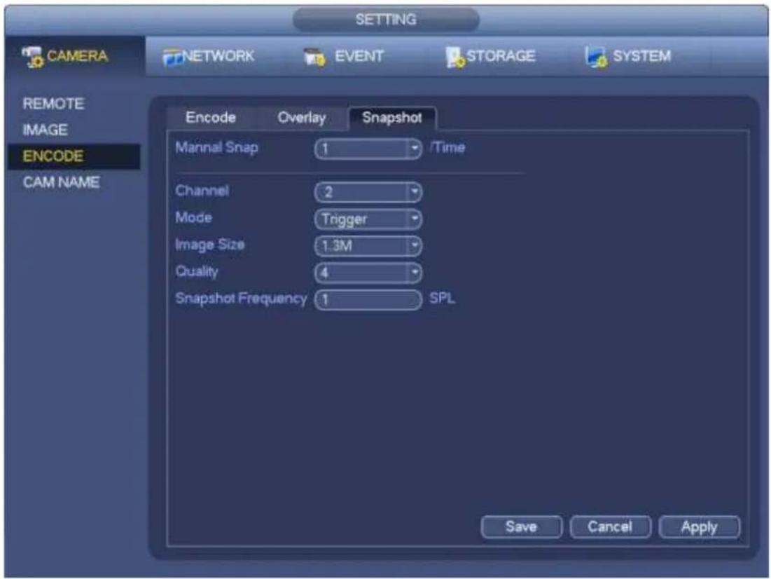
text_image
SETTING CAMERA NETWORK EVENT STORAGE SYSTEM REMOTE IMAGE ENCODE CAM NAME Encode Overlay Snapshot Mannal Snap 1 /Time Channel 2 Mode Trigger Image Size 1.3M Quality 4 Snapshot Frequency 1 SPL Save Cancel ApplyFigure 4-58
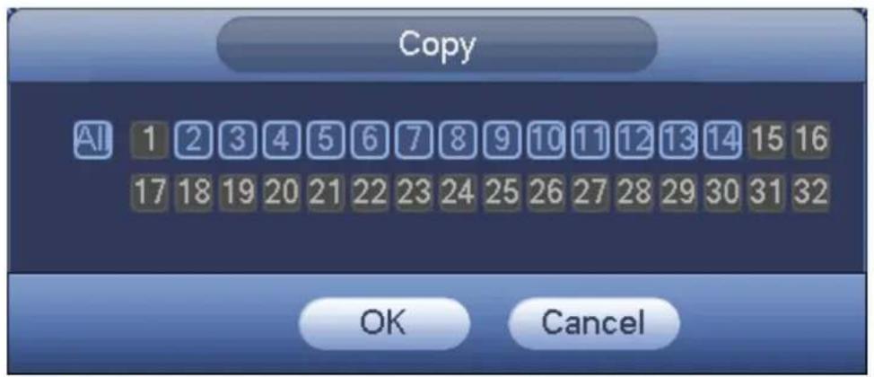
text_image
Copy AI 1 2 3 4 5 6 7 8 9 10 11 12 13 14 15 16 17 18 19 20 21 22 23 24 25 26 27 28 29 30 31 32 OK CancelFigure 4-59
4.10.2 Schedule
The record type priority is: Alarm>Motion detect>Regular.
4.10.2.1 Schedule Record
Set record time, record plan and etc. Please note system is in 24-hour record by default after its first boot up.
In the main menu, from Main menu->Setting->Storage->Schedule, you can go to schedule menu.
See Figure 4-63. There are total six periods.
- Channel: Please select the channel number first. You can select "all" if you want to set for the whole channels.
✿ : Sync connection icon. Select icon of several dates, all checked items can be edited or
together. Now the icon is shown as

: Click it to delete a record type from one period.
- Record Type: Please check the box to select corresponding record type. There are four types: Regular/MD (motion detect)/Alarm/MD&Alarm.
● Week day: There are eight options: ranges from Saturday to Sunday and all.
- Holiday: It is to set holiday setup. Please note you need to go to the General interface (Main Menu->Setting->System->General) to add holiday first. Otherwise you can not see this item.
● Pre-record: System can pre-record the video before the event occurs into the file. The value ranges from 1 to 30 seconds depending on the bit stream.
- Redundancy: System supports redundancy backup function. It allows you backup recorded file in two disks. You can highlight Redundancy button to activate this function. Please note, before enable this function, please set at least one HDD as redundant. (Main menu->Setting->Storage->HDD Manager). Please note this function is null if there is only one HDD.
- ANR: It is to save video to the SD card of the network camera in case the network connection fails. The value ranges from 0s\~43200s. After the network connection resumed, the system can get the video from the SD card and there is no risk of record loss.
- Period setup: Click button after one date or a holiday, you can see an interface shown as in Figure 4-64. There are four record types: regular, motion detection (MD), Alarm, MD & alarm.
Please following the steps listed below to draw the period manually.
a) Select a channel you want to set. See Figure 4-60.

text_image
Channel 1Figure 4-60
b) Set record type. See Figure 4-61.

text_image
Regular MD Alarm MD&AlarmFigure 4-61
c) Please draw manually to set record period. There are six periods in one day. See Figure 4-62.
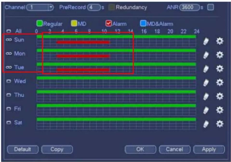
text_image
Channel 1 PreRecord 4 s Redundancy ANR 3600 s All 0 2 4 6 8 10 12 14 16 18 20 22 24 ∞ Sun ∞ Mon ∞ Tue Wed Thu Fri Sat Default Copy OK Cancel ApplyFigure 4-62
Please check the box ☐ to select the corresponding function. After completing all the setups please click save button, system goes back to the previous menu.
There are color bars for your reference. Green color stands for regular recording, yellow color stands for motion detection and red color stands for alarm recording. The white means the MD and alarm record is valid. Once you have set to record when the MD and alarm occurs, system will not record neither motion detect occurs nor the alarm occurs.
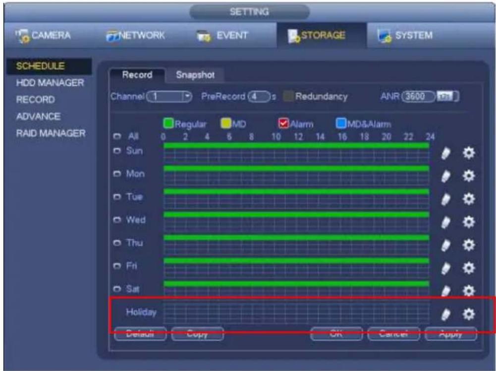
text_image
SETTING CAMERA NETWORK EVENT STORAGE SYSTEM SCHEDULE HDD MANAGER RECORD ADVANCE RAID MANAGER Record Snapshot Channel 1 PreRecord 4 s Redundancy ANR 3600 Regular MD Alarm MD&Alarm All 0 2 4 5 8 10 12 14 16 18 20 22 24 Sun Mon Tue Wed Thu Fri Sat Holiday Default Copy OK Cancel ApplyFigure 4-63
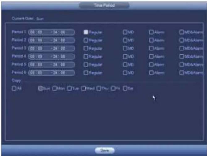
text_image
Time Period Current Date: Sun Period 1 00.00 -24.00 Regular MD Alarm MD&Alarm Period 2 00.00 -24.00 Regular MT Alarm MD&Alarm Period 3 00.00 -24.00 Regular MD Alarm MD&Alarm Period 4 00.00 -24.00 Regular MD Alarm MD&Alarm Period 5 00.00 -24.00 Regular MD Alarm MD&Alarm Period 6 00.00 -24.00 Regular MD Alarm MD&Alarm Copy All Sum Mon Tue Ward Thu Fri Sat SaveFigure 4-64
Quick Setup
Copy function allows you to copy one channel setup to another. After setting in channel 1, click Copy button, you can go to interface Figure 4-65. You can see current channel name is grey such as channel 1. Now you can select the channel you want to paste such as channel 5/6/7. If you want to save current setup of channel 1 to all channels, you can click the first box "ALL". Click the OK button to save current copy setup. Click the OK button in the Encode interface, the copy function succeeded.
Please note, if you select ALL in Figure 4-65, the record setup of all channels are the same and the Copy button becomes hidden.
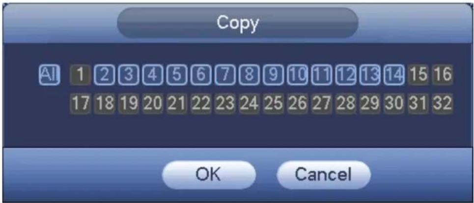
text_image
Copy AI 1 2 3 4 5 6 7 8 9 10 11 12 13 14 15 16 17 18 19 20 21 22 23 24 25 26 27 28 29 30 31 32 OK CancelFigure 4-65
Click OK button to save current setup.
4.10.2.2 Schedule Snapshot
From Main menu->Setting->Storage->Record or on the preview interface, right click mouse and then select record item, you can see Figure 4-66.
Select snapshot channel and enable snapshot function. Click Save button.
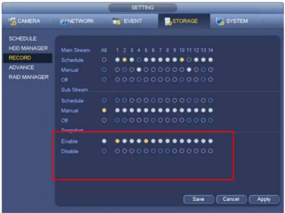
From Main menu->Setting->Camera->Encode->Snapshot, you can go to snapshot interface. See Figure 4-67.
Select the snapshot channel from the dropdown list and then select snapshot mode as Timing (Schedule) from the dropdown list and then set picture size, quality and snapshot frequency.
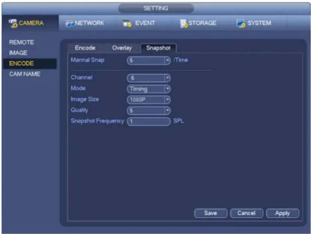
text_image
SETTING CAMERA NETWORK EVENT STORAGE SYSTEM REMOTE IMAGE ENCODE CAM NAME Encode Overlay Snapshot Mannal Snap 5 /Time Channel 6 Mode Timing Image Size 1080P Quality 5 Snapshot Frequency 1 SPL Save Cancel ApplyFigure 4-67
In the main menu, from Main menu->Setting->Storage->Schedule, you can go to schedule menu. See Figure 4-63. Here you can set snapshot period. There are total six periods in one day. Please refer to chapter 4.10.2.1 for detailed setup information. The setup steps are general the same.
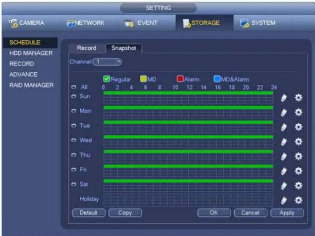
text_image
SETTING CAMERA NETWORK EVENT STORAGE SYSTEM SCHEDULE HDD MANAGER RECORD ADVANCE RAID MANAGER Record Snapshot Channel 1 Regular MD Alarm MD&Alarm All 0 2 4 6 8 10 12 14 16 18 20 22 24 Sun Mon Tue Wed Thu Fri Sat Holiday Default Copy OK Cancel ApplyFigure 4-68
Note
- Please note the trigger snapshot has the higher priority than regular snapshot. If you have enabled these two types at the same time, system can activate the trigger snapshot when an alarm occurs, and otherwise system just operates the regular snapshot.
- Only the trigger snapshot supports this function. The regular snapshot function can not send out picture via the email. But you can upload the picture to a FTP.
4.10.3 Motion detect record/snapshot
4.10.3.1 Motion detect record
a) From Main menu->Setting->Event->Detect, you can go to the following interface. See Figure 4-69.
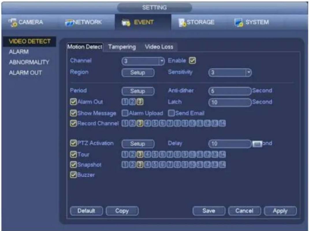
text_image
CAMERA NETWORK EVENT STORAGE SYSTEM VIDEO DETECT ALARM ABNORMALITY ALARM OUT Motion Detect Tampering Video Loss Channel 3 Enable ✓ Region Setup Sensitivity 3 Period Setup Anti-dither 5 Second ✓ Alarm Out 1 2 3 Latch 10 Second ✓ Show Message □ Alarm Upload □ Send Email ✓ Record Channel 1 2 3 4 5 6 7 8 9 10 11 12 13 ✓ PTZ Activation Setup Delay 10 and ✓ Tour 1 2 3 4 5 6 7 8 9 10 11 12 13 ✓ Snapshot 1 2 3 4 5 6 7 8 9 10 11 12 13 ✓ Buzzer Default Copy Save Cancel ApplyFigure 4-69
b) Select motion detect from the event type dropdown list. Select a channel from the dropdown list and then check the enable button to enable motion detect function.
c) Click Region Select button to set motion detect zone. There are 396(PAL)/330(NTSC) small zones. The green zone is current cursor position. Grey zone is the motion detection zone. Black zone is the disarmed zone. You can click Fn button to switch between the arm mode and disarm mode. In arm mode, you can click the direction buttons to move the green rectangle to set the motion detection zone. After you completed the setup, please click ENTER button to exit current setup. Do remember click save button to save current setup. If you click ESC button to exit the region setup interface system will not save your zone setup.
d) Period: Click set button, you can see an interface is shown as in Figure 4-92. Here you can set motion detect period. System only enables motion detect operation in the specified periods. It is not for video loss or the tampering. There are two ways for you to set periods. Please note system only supports 6 periods in one day.
In Figure 4-92, Select icon of several dates, all checked items can be edited together. Now
the icon is shown as Click to delete a record type from one period.
In Figure 4-92. Click button after one date or a holiday, you can see an interface shown as in Figure 4-93. There are four record types: regular, motion detection (MD), Alarm, MD & alarm.
e) Set sensitivity. Please note the sixth level has the highest sensitivity.
f) Click Save button to complete motion detect setup.
g) From Main menu->Setting->Storage->Schedule. See Figure 4-63
h) Set motion detect record channel, period and the record type shall be motion detect (MD). Please refer to chapter 4.10.2.
i) Click Copy button to copy current setup to other channel(s).
j) Click OK button to complete motion detect record setup.
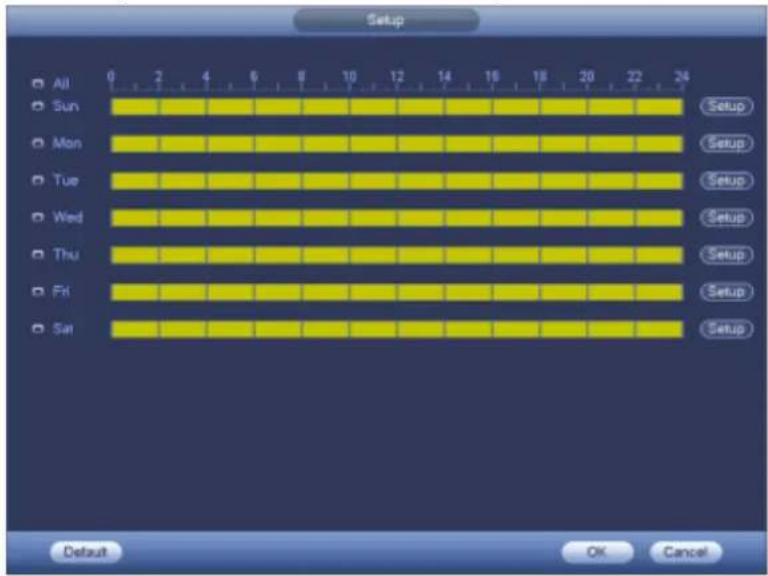
text_image
Setup All Sun Mon Tue Wed Thu Fri Sat 0 2 4 6 8 10 12 14 16 18 20 22 24 Setup Setup Setup Setup Setup Setup Setup Setup Default OK CancelFigure 4-70
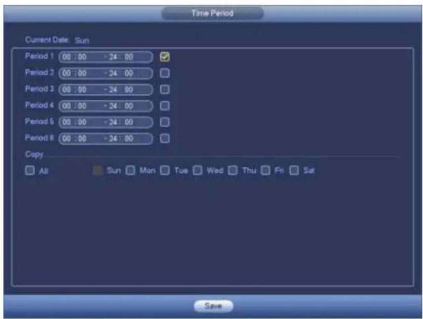
text_image
Time Period Current Date: Sun Period 1 00 : 00 - 24 : 00 ✓ Period 2 00 : 00 - 24 : 00 Period 3 00 : 00 - 24 : 00 Period 4 00 : 00 - 24 : 00 Period 5 00 : 00 - 24 : 00 Period 6 00 : 00 - 24 : 00 Copy All Sun Mon Tue Wed Thu Fri Sat SaveFigure 4-71
4.10.3.2 Motion Detect Snapshot
a) From Main menu->Setting->Camera->Encode->Snapshot, you can go to snapshot interface. See Figure 4-72.
b) In Figure 4-72, select trigger snapshot from the dropdown list and then set picture size, quality and snapshot frequency. Click OK button to save current setup.
c) From Main menu->Setting->Event->Detect, here you can select motion detect type, motion detect channel and then check the enable box. Please refer to chapter 4.10.3.1.
d) Click OK button to complete motion detect setup.
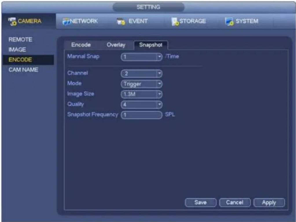
text_image
CAMERA NETWORK EVENT STORAGE SYSTEM REMOTE IMAGE ENCODE CAM NAME Encode Overlay Snapshot Mannal Snap 1 /Time Channel 2 Mode Trigger Image Size 1.3M Quality 4 Snapshot Frequency 1 SPL Save Cancel ApplyFigure 4-72
4.10.4 Alarm Record/Snapshot
4.10.4.1 Alarm Record
a) Before you set alarm setup information, please go to chapter 2.3 to connect alarm input and alarm output cable (such as light, siren and etc).
b) The record priority is: Alarm>Motion detect>Regular.
In the main menu, from Setting->Event->Alarm, you can see alarm setup interface. See Figure 4-73.
● Alarm in: Here is for you to select channel number.
● Event type: There are four types. Local input/network input/IPC external/IPC offline alarm.
Local input alarm: The alarm signal system detects from the alarm input port.
✨ Network input alarm: It is the alarm signal from the network.
✿ IPC external alarm: It is the on-off alarm signal from the front-end device and can activate the local NVR.
✿ IPC offline alarm: Once you select this item, system can generate an alarm when the front-end IPC disconnects with the local NVR. The alarm can activate record, PTZ, snapshot and etc. The alarm can last until the IPC and the NVR connection resumes.
● Enable: Please you need to highlight this button to enable current function.
● Type: normal open or normal close.
c) Click Save button to complete alarm setup interface.
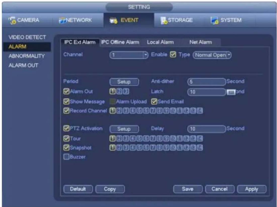
text_image
CAMERA NETWORK EVENT STORAGE SYSTEM VIDEO DETECT ALARM ABNORMALITY ALARM OUT IPC Ext Alarm IPC Offline Alarm Local Alarm Net Alarm Channel 1 Enable ✓ Type Normal Open Period Setup Anti-dither 5 Second ✓ Alarm Out 1 2 3 Latch 10 ✓ Show Message Alarm Upload ✓ Send Email ✓ Record Channel 1 2 3 4 5 6 7 8 9 10 11 12 13 14 ✓ PTZ Activation Setup Delay 10 Second ✓ Tour 1 2 3 4 5 6 7 8 9 10 11 12 13 14 ✓ Snapshot 1 2 3 4 5 6 7 8 9 10 11 12 13 14 ✓ Buzzer Default Copy Save Cancel ApplyFigure 4-73
d) From Mani menu->Setting->Storage->Schedule, you can go to Figure 4-63.
e) Select alarm channel, period and the record type shall be alarm. Please refer to chapter 4.10.2.
f) Click Copy button to copy current setup to other channel(s).
g) Click OK button to save alarm record information.
4.10.4.2 Alarm Snapshot
a) Please refer to Step a) to step c) of chapter 4.10.3.2 to enable timing snapshot.
b) From Main menu->Setting->Storage->schedule, you can go to Figure 4-74 to enable snapshot function.
c) From Main menu->Setting->Event->Alarm, you can go to Figure 4-73 to set alarm parameter and enable snapshot function.
d) Click Save button to save alarm snapshot setup.
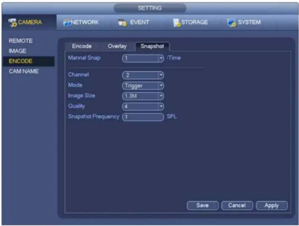
text_image
SETTING CAMERA NETWORK EVENT STORAGE SYSTEM REMOTE IMAGE ENCODE CAM NAME Encode Overlay Snapshot Mannal Snap 1 /Time Channel 2 Mode Trigger Image Size 1.3M Quality 4 Snapshot Frequency 1 SPL Save Cancel ApplyFigure 4-74
4.10.5 Manual Record/Snapshot
You need to have proper rights to implement the following operations. Please make sure the HDD has been properly installed.
4.10.5.1 Manual Record
a) Right click mouse and select manual record or in the main menu, from Setting->Storage->Manual Record. Manual record menu is shown as in Figure 4-75.
Tips
You can click Rec button on the front panel (if possible) to go to the Manual Record interface.
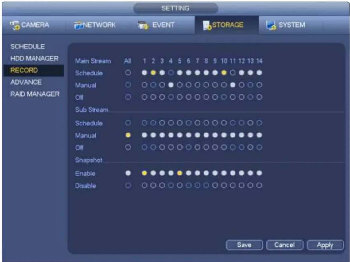
b) Check the box here to select manual record channel(s). You can see the corresponding indicator light on the front panel is on.
● Channel: It is to display device all channels.
- Manual: It has the highest priority. Enable corresponding channel to record no matter what period applied in the record setup. Now system is record general file.
- Auto: System enables auto record function as you set in chapter 4.10.2 schedule interface (General/Motion detect/Alarm)
- Stop: Stop current channel record/Snapshot no matter what period applied in the record setup.
● All: Check the All box to select all channels.
c) Click OK button to complete manual record setup.
4.10.5.2 Manual Snapshot
Click button at the preview control bar, you can snapshot 1-5 picture(s). From main menu->Setting->Camera->Encode->Snapshot, you can set snapshot times. You can go to chapter 4.11 to view snapshot picture.
4.10.6 Holiday Record/Snapshot
It is for you to set holiday record or snapshot plan. Please note the holiday record/snapshot setup has the higher priority than the ordinary date record/snapshot setup.
4.10.6.1 Holiday Record
a) From Mani menu->Setting->System->General, you can go to the following interface. See Figure
4-76.
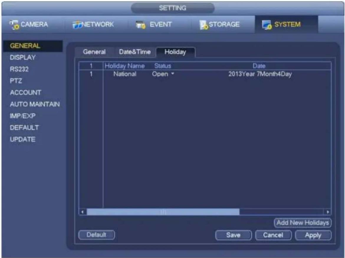
text_image
SETTING CAMERA NETWORK EVENT STORAGE SYSTEM GENERAL DISPLAY RS232 PTZ ACCOUNT AUTO MAINTAIN IMP/EXP DEFAULT UPDATE General Date&Time Holiday 1 Holiday Name Status Date 1 National Open 2013Year 7Month4Day Add New Holidays Default Save Cancel ApplyFigure 4-76
b) Click Add new holiday button, you can see an interface shown as in Figure 4-77. Here you can set holiday date name, repeat mode, start time/end time and etc.
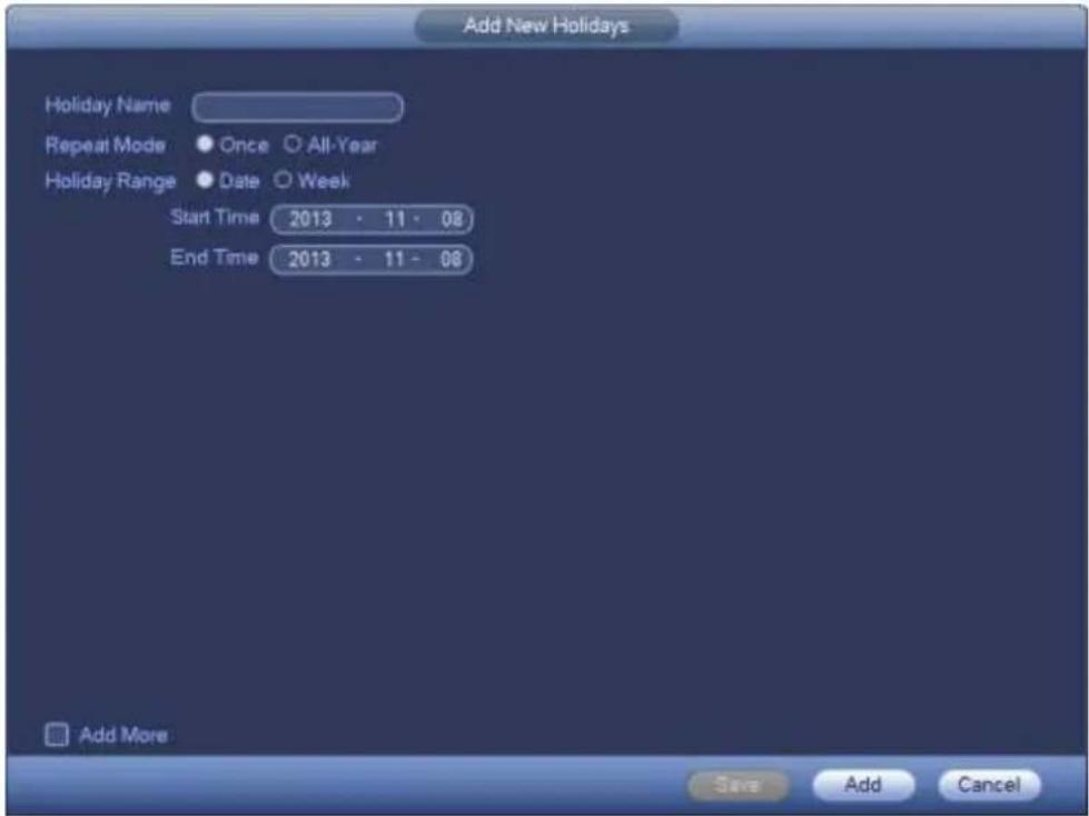
text_image
Add New Holidays Holiday Name Repeat Mode Once All-Year Holiday Range Date Week Start Time 2013 - 11 - 08 End Time 2013 - 11 - 08 Add More Save Add CancelFigure 4-77
c) Click Add button to complete holiday setup. Now you can enable holiday setup and then click Apply button.
d) From Main menu->setting->Storage->schedule, you can go to schedule interface. See Figure 4-78. Now you can set period and record type of holiday time. Please refer to chapter 4.10.2.1 for detailed setup information.
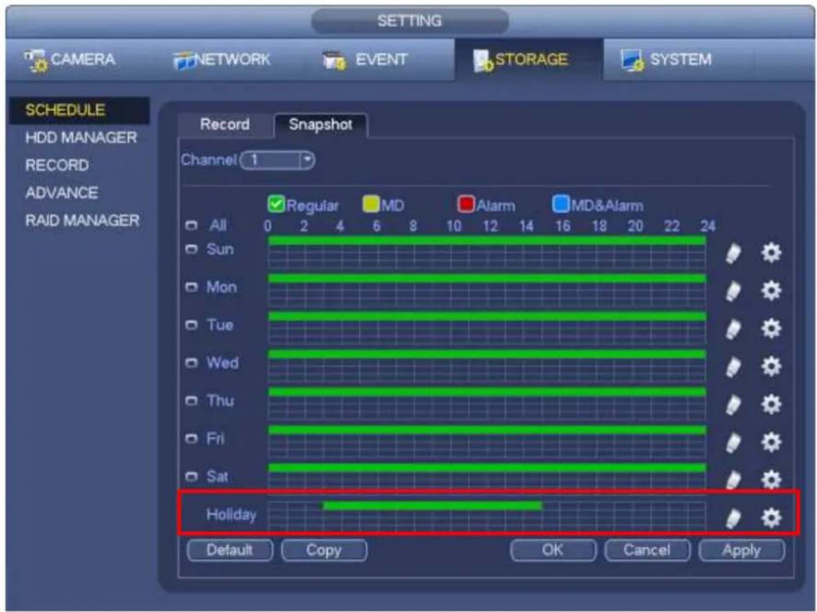
text_image
SETTING CAMERA NETWORK EVENT STORAGE SYSTEM SCHEDULE HDD MANAGER RECORD ADVANCE RAID MANAGER Record Snapshot Channel 1 Regular MD Alarm MD&Alarm All 0 2 4 6 8 10 12 14 16 18 20 22 24 Sun Mon Tue Wed Thu Fri Sat Holiday Default Copy OK Cancel ApplyFigure 4-78
e) Click OK button to set holiday record setup.
4.10.6.2 Holiday Snapshot
Set Holiday date first. Please refer to step a) to step c) of chapter 4.10.6.1.
From Main menu->Setting->Storage->Schedule, you can go to schedule interface. See Figure 4-78. Click Holiday item to set snapshot period.
Set holiday snapshot type (Trigger/Regular). Please refer to chapter 4.10.2.2 or chapter 4.10.3.2.
4.10.7 Other Record/Snapshot
Motion detect&Alarm record or snapshot, please refer to chapter 4.10.4.
Video loss or tampering record or snapshot function, please refer to chapter 4.10.3.
4.11 Playback and Search
4.11.1 Real-time Playback
Please refer to chapter 4.7.2 for real-time playback information.
4.11.2 Search Interface
From Main menu->Search, or on the preview interface right click mouse and then select search item, you can go to the following interface. See Figure 4-79.
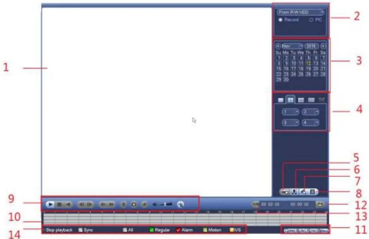
text_image
From R/W HDD Record PIC 2 Nov 2015 Su Mo Tu We Th Fr Sa 1 2 3 4 5 6 7 8 9 10 11 12 13 14 15 16 17 18 19 20 21 22 23 24 25 26 27 28 28 30 4 1 2 3 4 5 6 7 8 12 13 14 Stop playback Sync All Regular Alarm Motion MSFigure 4-79
Please refer to the following sheet for more information.
| SN | Name | Function | |
| 1 | Display window | ● Here is to display the searched picture or file.● Support 1/4/9/16-window playback. (It depends on the product channel amount). | |
| 2 | Search type | ● Here you can select to search the picture or the recorded file.● You can select to play from the read-write HDD, from peripheral device or from redundancy HDD.● Before you select to play from the peripheral device, please connect the corresponding peripheral device. You can view all record files of the root directory of the peripheral device. Click the Browse button; you can select the file you want to play.Important● Redundancy HDD does not support picture backup function, but it supports picture playback function. You can select to play from redundancy HDD if there are pictures on the redundancy HDD. | |
| 3 | Calendar | ● The blue highlighted date means there is picture or file. Otherwise, there is no picture or file.● In any play mode, click the date you want to see, you can see the corresponding record file trace in the time bar. | |
| 4 | Playback mode and channel selection pane. | ● Playback mode: 1/4/9/16. (It may vary due to different series.)◇ In 1-window playback mode: you can select 1-X channels (X depends on the product channel amount).◇ In 4-window playback mode: you can select 4 channels according to your requirement.◇ In 9-window playback mode, you can switch between 1-8, 9-16 and etc channels.◇ In 16-window playback mode, you can switch between 1-16, 17-32 and etc channels.● The time bar will change once you modify the playback mode or the channel option. | |
| 5 | Card number search | The card number search interface is shown as below. Here you can view card number/field setup bar. You can implement advanced search. Current series product supports this function. | |
| 6 | Face list | You can search when it is in 1-channel playback mode. Click it, system can filter all human faces and generate human face list. Double click the file; system begins playback the record or image of the corresponding human face. | |
| 7 | Mark file list button | Click it to go to mark file list interface. You can view all mark information of current channel by time. Please refer to chapter 4.11.2.3 for detailed information. Please note only the product of this icon supports mark function. | |
| 8 | File list switch button | ● Double click it, you can view the picture/record file list of current day.● The file list is to display the first channel of the record file.● The system can display max 128 files in one time. Use the ◀|and |► or the mouse to view the file. Select one item, and then double click the mouse or click the ENTER button to playback.● You can input the period in the following interface to begin accurate search.● File type: R—regular record; A—external alarm record; M—Motion detect record. ● Lock file. Click the file you want to lock and click the button to lock. The file you locked will not be overwritten.● Search locked file: Click the button ● Lock file. Click the file you want to lock and click the button to lock. The file you locked will not be overwritten.● Search locked file: Click the button  w the locked file. w the locked file. | |
| 9 | Playback control pane. | ►/II | Play/PauseThere are three ways for you to begin playback.● The play button● Double click the valid period of the time bar.● Double click the item in the file list.In slow play mode, click it to switch between play/pause. |
| ■ | Stop | ||
| ◄|◀/▶| | Backward playIn normal play mode, left click the button, the file begins backward play.Click it again to pause current play.In backward play mode, click ►/II to restore normal play.In playback mode, click it to play the next or the previous section. You can click continuously when you are watching the files from the same channel. In normal play mode, when you pause current play, you can click ◀| and |▶ to begin frame by frame playback. In frame by frame playback mode, click ▶/II to restore normal playback. | ||
| ▶ | Slow play In playback mode, click it to realize various slow play modes such as slow play 1, slow play 2, and etc. | ||
| ▶ | Fast forward In playback mode, click to realize various fast play modes such as fast play 1,fast play 2 and etc. | ||
| Note: The actual play speed has relationship with the software version. | |||
 | Smart search | ||
 | The volume of the playback | ||
 | Click the snapshot button in the full-screen mode, the system can snapshot 1 picture. System supports custom snap picture saved path. Please connect the peripheral device first, click snap button on the full-screen mode, you can select or create path. Click Start button, the snapshot picture can be saved to the specified path. | ||
 | Mark button. Please note this function is for some series product only. Please make sure there is a mark button in the playback control pane. You can refer to chapter 4.11.2.3 for detailed information. | ||
 | In 1-channel playback mode, click it to enable/disable display IVS rule information on the video. | ||
| 10 | Time bar | ● It is to display the record type and its period in current search criteria. ● In 4-window playback mode, there are corresponding four time bars. In other playback mode, there is only one time bar. ● Use the mouse to click one point of the color zone in the time bar, system begins playback. ● The time bar is beginning with 0 o'clock when you are setting the configuration. The time bar zooms in the period of the current playback time when you are playing the file. ● The green color stands for the regular record file. The red color stands for the external alarm record file. The yellow stands for the motion detect record file. | |
| 11 | Time bar unit | ●The option includes: Q24hr、+2hr、+1hr和+30min. The smaller the unit, the larger the zoom rate. You can accurately set the time in the time bar to playback the record. ● The time bar is beginning with 0 o'clock when you are setting the configuration. The time bar zooms in the period of the current playback time when you are playing | |
| the file. | |||
| 12 | Backup | Select the file(s) you want to backup from the file list. You can check from the list. Then click the backup button, now you can see the backup menu. System supports customized path setup. After select or create new folder, click the Start button to begin the backup operation. The record file(s) will be saved in the specified folder.Check the file again you can cancel current selection. System max supports to display 32 files from one channel.After you clip on record file, click Backup button you can save it.For one device, if there is a backup in process, you can not start a new backup operation. | |
| 13 | Clip | It is to edit the file.Please click to play the file you want to edit.Select clip start time on the time bar and then Click  clip.Select clip stop time on the time bar and then click clip.Select clip stop time on the time bar and then click  clip.Click , system pops up file backup dialogue box for you to save.Please note:Clip function is for one-channel mode/multiple-channel mode.System max supports 1024 files backup at the same time.You can not operate clip operation if there is any file has been checked in the file list. clip.Click , system pops up file backup dialogue box for you to save.Please note:Clip function is for one-channel mode/multiple-channel mode.System max supports 1024 files backup at the same time.You can not operate clip operation if there is any file has been checked in the file list. | |
| 14 | Record type | In any play mode, the time bar will change once you modify the search type. | |
| Other Functions | |||
| 15 | Smart search | When system is playing, you can select a zone in the window to begin smart search. Click the motion detect button to begin play.Once the motion detect play has begun, click button again will terminate current motion detect file play.There is no motion detect zone by default.If you select to play other file in the file list, system switches to motion detect play of other file.During the motion detect play process, you can not implement operations such as change time bar, begin backward playback or frame by frame playback.Please refer to chapter 4.11.2.1 Smart Search for detailed operation. | |
| 16 | Other channel synchronization switch toplaywhen playback | When playing the file, click the number button, system can switch to the same period of the corresponding channel to play. | |
| 17 | Digital zoom | When the system is in full-screen playback mode, left click the mouse in the screen. Drag your mouse in the screen to select a section and then left click mouse to realize digital zoom. You can right click mouse to exit. | |
| 18 | Manually switch channel when playback | During the file playback process, you can switch to other channel via the dropdown list or rolling the mouse.This function is null if there is no record file or system is in smart search process. | |
Note:
All the operations here (such as playback speed, channel, time and progress) have relationship with hardware version. Some series NVRs do not support some functions or playback speeds.
4.11.2.1 Smart Search
During the multiple-channel playback mode, double click one channel and then click the button, system begins smart search. System supports 396(22*18 PAL) and 330(22*15 NTSC) zones. Please left click mouse to select smart search zones. See Figure 4-80.
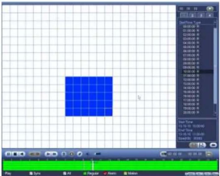
text_image
Play Sync Alt Regular Alert Motion Start Time 00:00:00 R 01:00:00 R 02:00:00 R 03:00:00 R 04:00:00 R 05:00:00 R 06:00:00 R 07:00:00 R 08:00:00 R 09:00:00 R 10:00:00 R 11:00:00 R 12:00:00 R 13:00:00 R 14:00:00 R 15:00:00 R 16:00:00 R 17:00:00 R 18:00:00 R 19:00:00 R 20:00:00 R Start Time 13:13:13 13:00:13D End Time 13:13:13 13:01:13D Sequence ID: 163223Figure 4-80

Click the, you can go to the smart search playback. Click it again, system stops smart search playback.
Important
- System does not support motion detect zone setup during the full-screen mode.
- During the multiple-channel playback, system stops playback of rest channels if you implement one-channel smart search.
4.11.2.2 Accurate playback by time
Select records from one day, click the list, you can go to the file list interface. You can input time at the top right corner to search records by time. See image on the left side of the Figure 4-81 For example, input

time 11:00.00 and then click Search button, you can view all the record files after 11:00.00 (The records includes current time.). See image on the right side of the Figure 4-81 Double click a file name to playback.
Note
- After you searched files, system implement accurate playback once you click Play for the first time.
- System does not support accurate playback for picture.
- System supports synchronization playback and non-synchronous playback. The synchronization playback supports all channels and non-synchronous playback only supports accurately playback of current select channel.
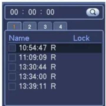
text_image
00 : 00 : 00 1 2 3 4 Name Lock 10:54:47 R 11:09:09 R 13:30:44 R 13:34:00 R 13:39:11 R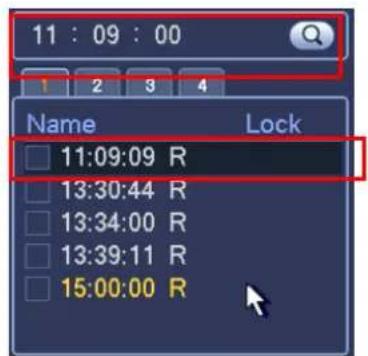
text_image
11 : 09 : 00 1 2 3 4 Name Lock 11:09:09 R 13:30:44 R 13:34:00 R 13:39:11 R 15:00:00 RFigure 4-81
4.11.2.3 Mark Playback
Please make sure your purchased device support this function. You can use this function only if you can see the mark playback icon on the Search interface (Figure 4-79).
When you are playback record, you can mark the record when there is important information. After playback, you can use time or the mark key words to search corresponding record and then play. It is very easy for you to get the important video information.
- Add Mark
When system is playback, click Mark button, you can go to the following interface. See Figure 4-82.
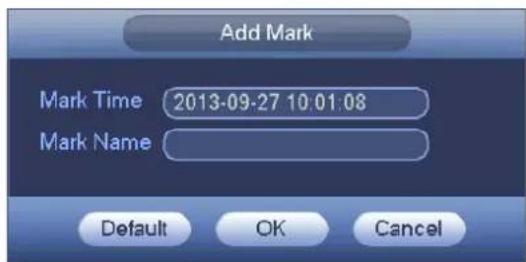
text_image
Add Mark Mark Time 2013-09-27 10:01:08 Mark Name Default OK CancelFigure 4-82
- Playback Mark
During 1-window playback mode, click mark file list button in Figure 4-79, you can go to mark file list
interface. Double click one mark file, you can begin playback from the mark time.
● Play before mark time
Here you can set to begin playback from previous N seconds of the mark time.
Note
Usually, system can playbacks previous N seconds record if there is such kind of record file. Otherwise, system playbacks from the previous X seconds when there is such as kind of record.
- Mark Manager
Click the mark manager button on the Search interface (Figure 4-79); you can go to Mark Manager interface. See Figure 4-83. System can manage all the record mark information of current channel by default. You can view all mark information of current channel by time.

text_image
Marks Manager Channel 1 Start Time 2013 - 09 - 27 00 : 00 : 00 End Time 2013 - 09 - 28 00 : 00 : 00 Search 1 CH Mark Time Mark Name 1 1 2013-09-27 10:00:12 report Delete ExitFigure 4-83
- Modify
Double click one mark information item, you can see system pops up a dialogue box for you to change mark information. You can only change mark name here.
- Delete
Here you can check the mark information item you want to delete and then click Delete button, you can remove one mark item. .
Note
- After you go to the mark management interface, system needs to pause current playback. System resume playback after you exit mark management interface.
- If the mark file you want to playback has been removed, system begin playback from the first file in the list.
4.11.3 Picture Playback
a) From Main menu->Search, or on the preview interface right click mouse, you can go to Figure 4-79.
b) At the top right pane, you can check the box to select picture and then select playback interval.
c) Please refer to chapter 4.11.2 to select picture you want to view.
4.12 Backup
4.12.1 File Backup
In this interface, you can backup record file to the USB device.
a) Connect USB burner, USB device or portable HDD and etc to the device.
b) From Main menu->Backup, you can go to the Backup interface. See Figure 4-84
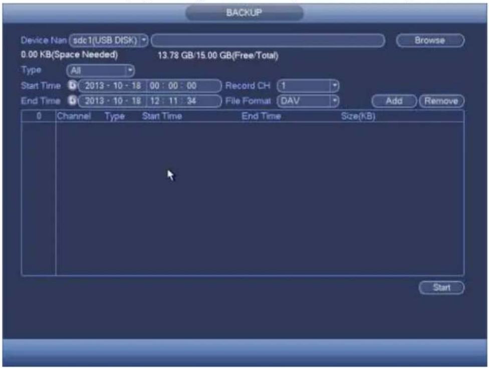
text_image
BACKUP Device Nan sdc1(USB DISK) Browse 0.00 KB(Space Needed) 13.78 GB/15.00 GB(Free/Total) Type All Start Time 2013 - 10 - 18 00 : 00 : 00 Record CH 1 End Time 2013 - 10 - 18 12 : 11 : 34 File Format DAV Add Remove 0 Channel Type Start Time End Time Size(kB) StartFigure 4-84
c) Select backup device and then set channel, file start time and end time.
d) Click add button, system begins search. All matched files are listed below. System automatically calculates the capacity needed and remained. See Figure 4-85.
e) System only backup files with a √ before channel name. You can use Fn or cancel button to delete √ after file serial number.
f) Click backup button, you can backup selected files. There is a process bar for you reference.
g) When the system completes backup, you can see a dialogue box prompting successful backup.
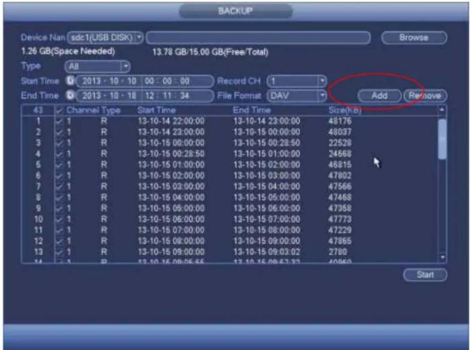
text_image
BACKUP Device Nan sdc1(USB DISK) Browse 1.26 GB(Space Needed) 13.78 GB/15.00 GB(Free/Total) Type All Start Time 0 2013 - 10 - 10 00 : 00 : 00 Record CH 1 End Time 0 2013 - 10 - 18 12 : 11 : 34 File Format DAV Add Remove 43 Channel Type Start Time End Time Size(kb) 1 ✓ 1 R 13-10-14 22:00:00 13-10-14 23:00:00 48176 2 ✓ 1 R 13-10-14 23:00:00 13-10-15 00:00:00 48037 3 ✓ 1 R 13-10-15 00:00:00 13-10-15 00:28:50 22528 4 ✓ 1 R 13-10-15 00:28:50 13-10-15 01:00:00 24668 5 ✓ 1 R 13-10-15 01:00:00 13-10-15 02:00:00 46815 6 ✓ 1 R 13-10-15 02:00:00 13-10-15 03:00:00 47892 7 ✓ 1 R 13-10-15 03:00:00 13-10-15 04:00:00 47566 8 ✓ 1 R 13-10-15 04:00:00 13-10-15 05:00:00 47468 9 ✓ 1 R 13-10-15 05:00:00 13-10-15 06:00:00 47359 10 ✓ 1 R 13-10-15 06:00:00 13-10-15 07:00:00 47773 11 ✓ 1 R 13-10-15 07:00:00 13-10-15 08:00:00 47229 12 ✓ 1 R 13-10-15 08:00:00 13-10-15 09:00:00 47865 13 ✓ 1 R 13-10-15 09:00:00 13-10-15 09:33:22 2789 StartFigure 4-85
h) Click backup button, system begins burning. At the same time, the backup button becomes stop button. You can view the remaining time and process bar at the left bottom.
Note
● During backup process, you can click ESC to exit current interface for other operation (For some series product only). The system will not terminate backup process.
- The file name format usually is: Channel number+Record type+Time. In the file name, the YDM format is Y + M + D + H + M + S . File extension name is .day.
This function allows you to copy current system configuration to other devices. It also supports import, create new folder, and delete folder and etc function.
From Main menu->Setting->System->Import/Export, you can see the configuration file backup interface is shown as below. See Figure 4-86.
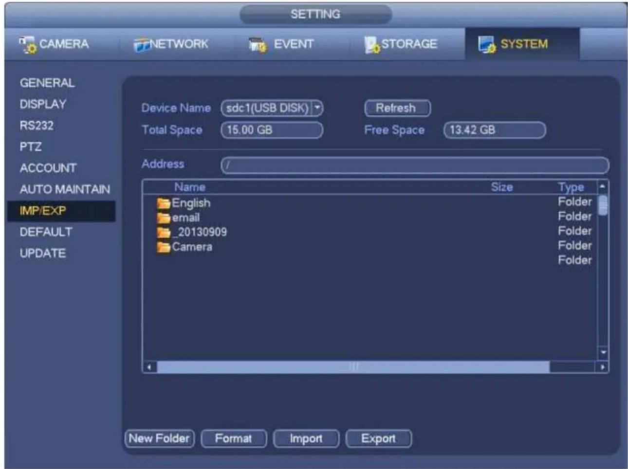
text_image
SETTING CAMERA NETWORK EVENT STORAGE SYSTEM GENERAL DISPLAY RS232 PTZ ACCOUNT AUTO MAINTAIN IMP/EXP DEFAULT UPDATE Device Name sdc1(USB DISK) Refresh Total Space 15.00 GB Free Space 13.42 GB Address / Name Size Type English Folder email Folder _20130909 Folder Camera Folder New Folder Format Import ExportFigure 4-86
- Export: Please connect the peripheral device first and then go to the following interface. Click Export button, you can see there is a corresponding "Config_Time" folder. Double click the folder, you can view some backup files.
- Import: Here you can import the configuration files from the peripheral device to current device. You need to select a folder first. You can see a dialogue box asking you to select a folder if you are selecting a file. System pops up a dialogue box if there is no configuration file under current folder. After successfully import, system needs to reboot to activate new setup.
- Format: Click Format button, system pops up a dialogue box for you to confirm current operation. System begins format process after you click the OK button.
Note:
● System can not open config backup interface again if there is backup operation in the process.
- System refreshes device when you go to the config backup every time and set current directory as the root directory of the peripheral device.
- If you go to the configuration backup interface first and then insert the peripheral device, please click Refresh button to see the newly added device.
4.12.3 Backup Log
a) From Main menu->Info->Log, the interface is shown as below. See Figure 4-87.
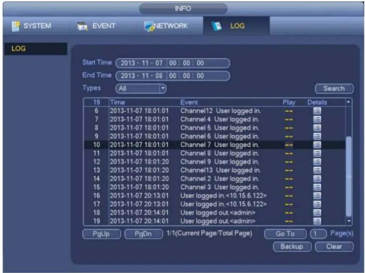
text_image
INFO SYSTEM EVENT NETWORK(LOG LOG Start Time 2013 - 11 - 07 00 : 00 : 00 End Time 2013 - 11 - 08 00 : 00 : 00 Types All Search 19 Time Event Play Details 6 2013-11-07 18:01:01 Channel12 User logged in. -- 7 2013-11-07 18:01:01 Channel 4 User logged in. -- 8 2013-11-07 18:01:01 Channel 5 User logged in. -- 9 2013-11-07 18:01:01 Channel 6 User logged in. -- 10 2013-11-07 18:01:01 Channel 7 User logged in. -- 11 2013-11-07 18:01:01 Channel 8 User logged in. -- 12 2013-11-07 18:01:20 Channel 9 User logged in. -- 13 2013-11-07 18:01:20 Channel13 User logged in. -- 14 2013-11-07 18:01:20 Channel 2 User logged in. -- 15 2013-11-07 18:01:20 Channel 3 User logged in. -- 16 2013-11-07 20:13:01 User logged in. <10.15.6.122> 17 2013-11-07 20:13:01 User logged in. <10.15.6.122> 18 2013-11-07 20:14:01 User logged outFigure 4-87
b) Select log type and then set start time/end time, click Search button, you can see log time and event information. Click to view detailed log information.
c) Select log items you want to save and then click backup button, you can select a folder to save them. Click Start to backup and you can see the corresponding dialogue box after the process is finish.
4.12.4 USB Device Auto Pop-up
After you inserted the USB device, system can auto detect it and pop up the following dialogue box. It allows you to conveniently backup file, log, configuration or update system. See Figure 4-88. Please refer to chapter 4.12.1 file backup, chapter 4.12.3 backup log, chapter 4.12.2 import/export, and chapter 4.11.2 search for detailed information.
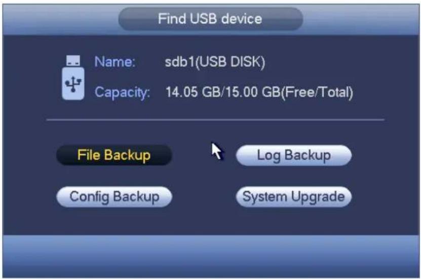
text_image
Find USB device Name: sdb1(USB DISK) Capacity: 14.05 GB/15.00 GB(Free/Total) File Backup Log Backup Config Backup System UpgradeFigure 4-88
4.13 Alarm
4.13.1 Detect Alarm
In the main menu, from Setting to Detect, you can see motion detect interface. See Figure 4-89.There are three detection types: motion detection, video loss, tampering.
4.13.1.1 Motion Detect
After analysis video, system can generate a motion detect alarm when the detected moving signal reached the sensitivity you set here.
Detection menu is shown as below. See Figure 4-89.
- Event type: From the dropdown list you can select motion detection type.
- Channel: Select a channel from the dropdown list to set motion detect function.
● Enable: Check the box here to enable motion detect function.
- Region: Click select button, the interface is shown as in Figure 4-90. Here you can set motion detection zone. There are four zones for you to set. Please select a zone first and then left drag the mouse to select a zone. The corresponding color zone displays different detection zone. You can click Fn button to switch between the arm mode and disarm mode. In arm mode, you can click the direction buttons to move the green rectangle to set the motion detection zone. After you completed the setup, please click ENTER button to exit current setup. Do remember click save button to save current setup. If you click ESC button to exit the region setup interface system will not save your zone setup.
● Sensitivity: System supports 6 levels. The sixth level has the highest sensitivity.
- Anti-dither: Here you can set anti-dither time. The value ranges from 5 to 600s. The anti-dither time refers to the alarm signal lasts time. It can be seen as the alarm signal activation stays such as the buzzer, tour, PTZ activation, snapshot, channel record. The stay time here does not include the latch time. During the alarm process, the alarm signal can begin an anti-dither time if system detects the local alarm again. The screen prompt, alarm upload, email and etc will not be activated. For example, if you set the anti-dither time as 10 second, you can see the each activation may last 10s if the local alarm is activated. During the process, if system detects another local alarm signal at the fifth second, the buzzer, tour, PTZ activation, snapshot, record channel will begin another 10s while the
screen prompt, alarm upload, email will not be activated again. After 10s, if system detects another alarm signal, it can generate an alarm since the anti-dither time is out.
- Period: Click set button, you can see an interface is shown as in Figure 4-92. Here you can set motion detect period. System only enables motion detect operation in the specified periods. It is not for video loss or the tampering. There are two ways for you to set periods. Please note system only supports 6 periods in one day.
In Figure 4-92, Select icon of several dates, all checked items can be edited together. Now
the icon is shown as Click to delete a record type from one period.
In Figure 4-92. Click button after one date or a holiday, you can see an interface shown as in Figure 4-93. There are four record types: regular, motion detection (MD), Alarm, MD & alarm.
- Alarm output: when an alarm occurs, system enables peripheral alarm devices.
- Latch: when motion detection complete, system auto delays detecting for a specified time. The value ranges from 1-300(Unit: second)
● Show message: System can pop up a message to alarm you in the local host screen if you enabled this function. - Alarm upload: System can upload the alarm signal to the network (including alarm centre) if you enabled current function.
- Send email: System can send out email to alert you when an alarm occurs.
- Record channel: System auto activates motion detection channel(s) to record once an alarm occurs. Please make sure you have set MD record in Schedule interface(Main Menu->Setting->Schedule) and schedule record in manual record interface(Main Menu->Advanced->Manual Record)
- PTZ activation: Here you can set PTZ movement when an alarm occurs. Such as go to preset, tour &pattern when there is an alarm. Click "select" button, you can see an interface is shown as in Figure 4-91.
- Record Delay: System can delay the record for specified time after alarm ended. The value ranges from 10s to 300s.
● Tour: Here you can enable tour function when alarm occurs. System one-window tour. - Snapshot: You can enable this function to snapshot image when a motion detect alarm occurs.
- Video matrix Check the box here to enable this function. When an alarm occurs, SPOT OUT port displays device video output. It displays video (1-window tour) from alarm activation channel you select at the Record channel item.
- Buzzer: Highlight the icon to enable this function. The buzzer beeps when alarm occurs.
Please highlight icon ☐ to select the corresponding function. After all the setups please click save button, system goes back to the previous menu.
Note:
In motion detection mode, you can not use copy/paste to set channel setup since the video in each channel may not be the same.
In Figure 4-90, you can left click mouse and then drag it to set a region for motion detection. Click Fn to switch between arm/withdraw motion detection. After setting, click enter button to exit.
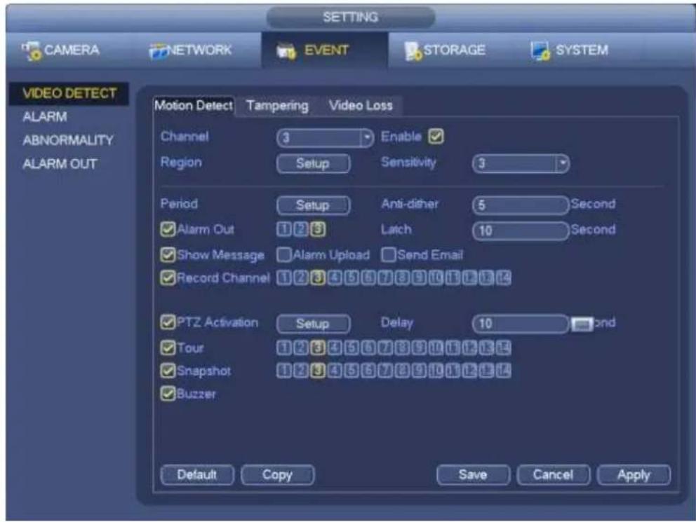
text_image
SETTING CAMERA NETWORK EVENT STORAGE SYSTEM VIDEO DETECT ALARM ABNORMALITY ALARM OUT Motion Detect Tampering Video Loss Channel 3 Enable ✓ Region Setup Sensitivity 3 Period Setup Anti-disher 5 Second ✓ Alarm Out 1 2 3 Latch 10 Second ✓ Show Message ☐ Alarm Upload ☐ Send Email ✓ Record Channel 1 2 3 4 5 6 7 8 9 10 11 12 13 14 ✓ PTZ Activation Setup Delay 10 second ✓ Tour 1 2 3 4 5 6 7 8 9 10 11 12 13 14 ✓ Snapshot 1 2 3 4 5 6 7 8 9 10 11 12 13 14 ✓ Buzzer Default Copy Save Cancel ApplyFigure 4-89
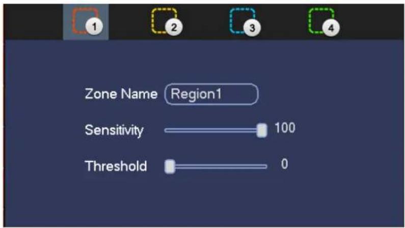
text_image
Zone Name Region1 Sensitivity 100 Threshold 0Figure 4-90
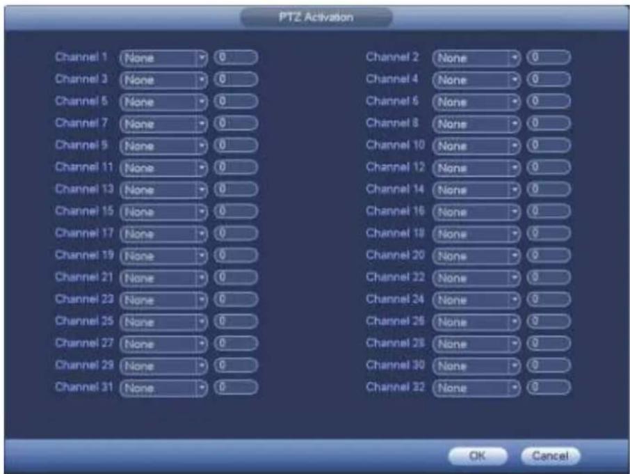
text_image
PTZ Activation Channel 1 None 0 Channel 2 None 0 Channel 3 None 0 Channel 4 None 0 Channel 5 None 0 Channel 6 None 0 Channel 7 None 0 Channel 8 None 0 Channel 9 None 0 Channel 10 None 0 Channel 11 None 0 Channel 12 None 0 Channel 13 None 0 Channel 14 None 0 Channel 15 None 0 Channel 16 None 0 Channel 17 None 0 Channel 18 None 0 Channel 19 None 0 Channel 20 None 0 Channel 21 None 0 Channel 22 None 0 Channel 23 None 0 Channel 24 None 0 Channel 25 None 0 Channel 26 None 0 Channel 27 None 0 Channel 28 None 0 Channel 29 None 0 Channel 30 None 0 Channel 31 None 0 Channel 32 None 0 OK CancelFigure 4-91
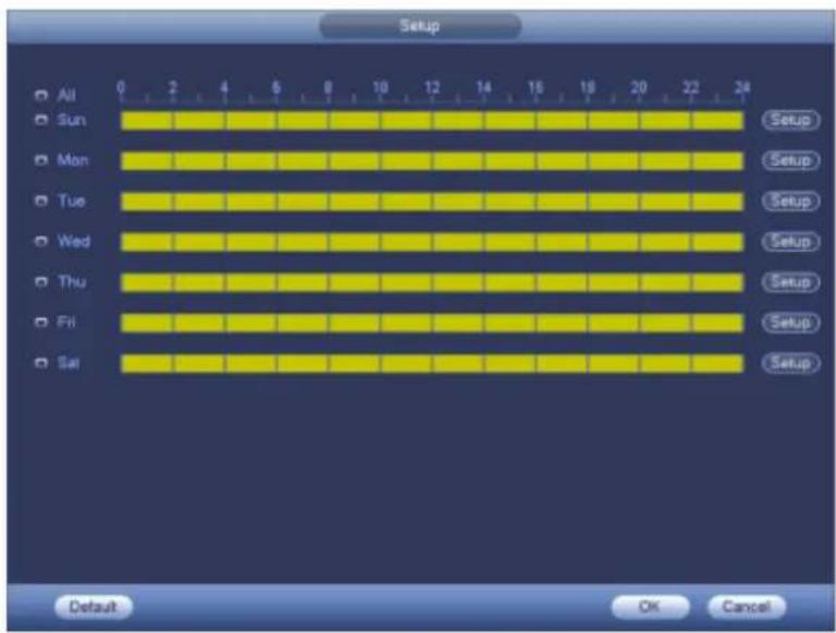
text_image
Setup All Sun Mon Tue Wed Thu Fri Sat 0 2 4 6 8 10 12 14 16 18 20 22 24 Setup Setup Setup Setup Setup Setup Setup Setup Default OK CancelFigure 4-92
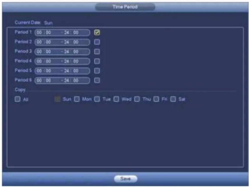
text_image
Time Period Current Date: Sun Period 1 00:00 -24:00 Period 2 00:00 -24:00 Period 3 00:00 -24:00 Period 4 00:00 -24:00 Period 5 00:00 -24:00 Period 6 00:00 -24:00 Copy All Sun Mon Tue Wed Thu Fri Sat SaveFigure 4-93
Motion detect here only has relationship with the sensitivity and region setup. It has no relationship with other setups.
4.13.1.2 Tampering
When someone viciously masks the lens, or the output video is in one-color due to the environments light change, the system can alert you to guarantee video continuity. Tampering interface is shown as in Figure 4-94. You can enable “Alarm output” or “Show message” function when tampering alarm occurs.
- Sensitivity: The value ranges from 1 to 6. It mainly concerns the brightness. The level 6 has the higher sensitivity than level 1. The default setup is 3.
Tips:
You can enable preset/tour/pattern activation operation when video loss occurs.
Please refer to chapter 4.13.1.1 motion detection for detailed information.
Note:
- In Detect interface, copy/paste function is only valid for the same type, which means you can not copy a channel setup in video loss mode to tampering mode.
- About Default function. Since detection channel and detection type may not be the same, system can only restore default setup of current detect type. For example, if you click Default button at the tampering interface, you can only restore default tampering setup. It is null for other detect types.
- System only enables tampering function during the period you set here. It is null for motion detect or video loss type.
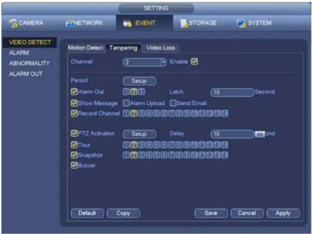
text_image
SETTING CAMERA NETWORK EVENT STORAGE SYSTEM VIDEO DETECT ALARM ABNORMALITY ALARM OUT Motion Detect Tampering Video Loss Channel 2 Enable ✓ Period Setup ✓ Alarm Out 1 2 3 Latch 10 Second ✓ Show Message ☐ Alarm Upload ☐ Send Email ✓ Record Channel 1 2 3 4 5 6 7 8 9 10 11 12 13 14 ✓ PTZ Activation Setup Delay 10 second ✓ Tour 1 2 3 4 5 6 7 8 9 10 11 12 13 14 ✓ Snapshot 1 2 3 4 5 6 7 8 9 10 11 12 13 14 ✓ Buzzer Default Copy Save Cancel ApplyFigure 4-94
4.13.1.3 Video Loss
In Figure 4-89, select video loss from the type list. You can see the interface is shown as in Figure 4-95. This function allows you to be informed when video loss phenomenon occurred. You can enable alarm output channel and then enable show message function.
You can refer to chapter 4.13.1.1 Motion detect for detailed information.
Tips:
You can enable preset/tour/pattern activation operation when video loss occurs.
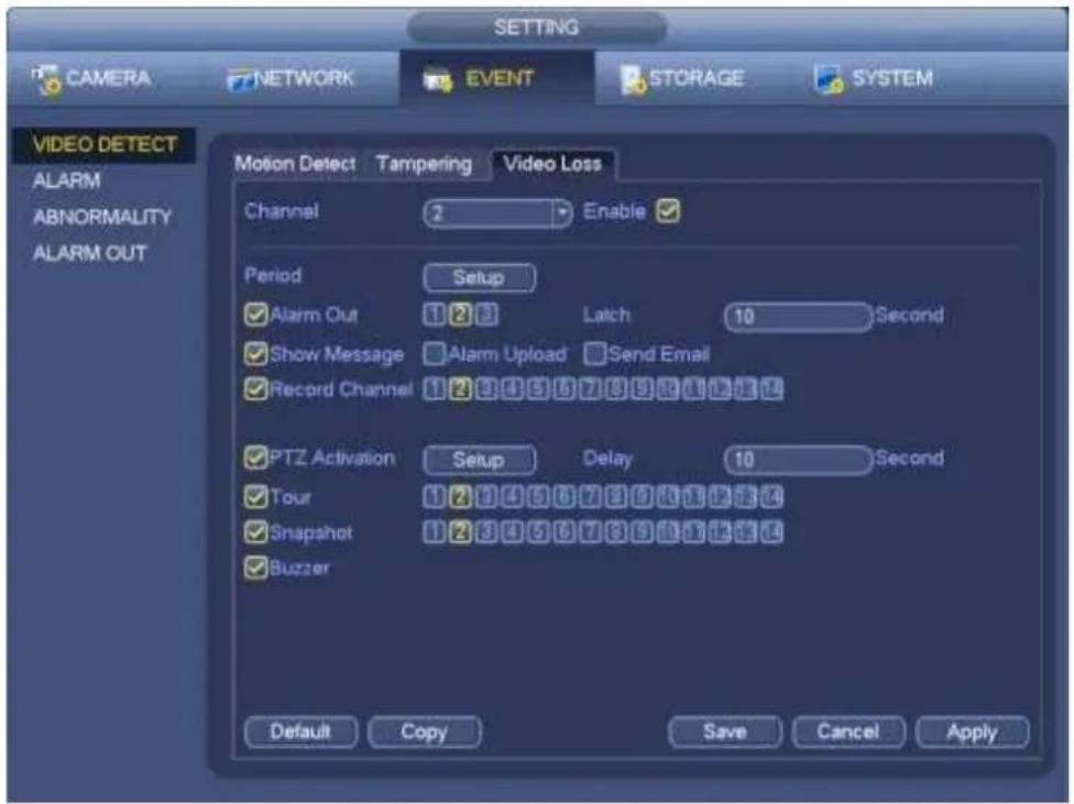
text_image
SETTING CAMERA NETWORK EVENT STORAGE SYSTEM VIDEO DETECT ALARM ABNORMALITY ALARM OUT Motion Detect Tampering Video Loss Channel 2 Enable ✓ Period Setup ✓ Alarm Out 1 2 3 Latch 10 Second ✓ Show Message Alarm Upload Send Email ✓ Record Channel 1 2 3 4 5 6 7 8 9 10 11 12 13 ✓ PTZ Activation Setup Delay 10 Second ✓ Tour 1 2 3 4 5 6 7 8 9 10 11 12 13 ✓ Snapshot 1 2 3 4 5 6 7 8 9 10 11 12 13 ✓ Buzzer Default Copy Save Cancel ApplyFigure 4-95
4.13.2 IVS (Optional)

Please make sure you are connecting to the smart network camera, otherwise you can not
use IVS function!
From main menu->Setting->Event, you can go to the IVS interface. It includes four interfaces: Tripwire/intrusion/object/scene.
4.13.2.1 Tripwire (Optional)
Please make sure you are connecting to the smart network camera, otherwise you can not use IVS function!
System generates an alarm once there is any object crossing the tripwire in the specified direction. From main menu->Setting->Event->IVS->Tripwire, the interface is shown as below. See Figure 4-96.
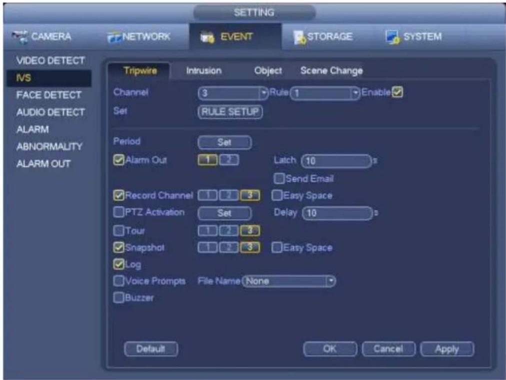
text_image
CAMERA NETWORK EVENT STORAGE SYSTEM VIDEO DETECT IVS FACE DETECT AUDIO DETECT ALARM ABNORMALITY ALARM OUT Tripwire Intrusion Object Scene Change Channel 3 Rule 1 Enable Set RULE SETUP Period Set ✓ Alarm Out 1 2 Latch 10 s Send Email ✓ Record Channel 1 2 3 Easy Space PTZ Activation Set Delay 10 s Tour 1 2 3 ✓ Snapshot 1 2 3 Easy Space ✓ Log ✓ Voice Prompts File Name None ✓ Buzzer Default OK Cancel ApplyFigure 4-96
Check the Enable box to enable tripwire function.
Click Rule setup to draw the tripwire. See Figure 4-97.
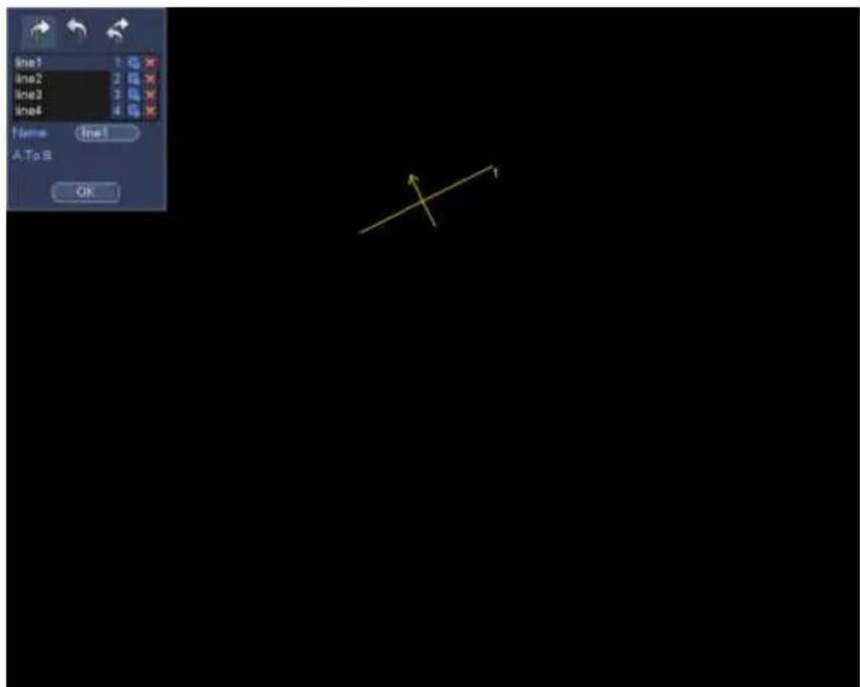
text_image
line1 line2 line3 line4 Name: line1 A,To S OKFigure 4-97
Select SN (Line1/2/3/4) and direction, and then input customized rule name.
- Line1/2/3/4: System supports four tripwires. Each SN stands for one tripwire.

- Direction (//): System can generate an alarm once there is any object crossing in the specified direction.
Now you can draw a rule. Left click mouse to draw a tripwire. The tripwire can be a direct line, curve or polygon. Right click mouse to complete.
Click to draw filter object.
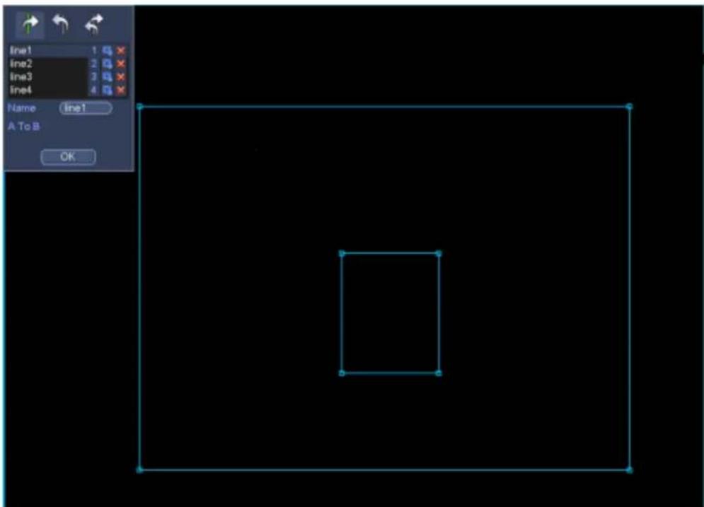
text_image
line1 line2 line3 line4 Name: line1 A To B OKFigure 4-98
Select the blue line and then use mouse to adjust zone size.
Note
Each rule can set two sizes (min size/max size). Once the object is smaller than the min size or larger than the max size, there is no alarm. Please make sure the max size is larger than the min size.
Click Ok to complete the rule setup.
Tips
Click ☒ to delete the corresponding rule.
You can refer to the following information to set other parameters.
- Channel: Select a channel from the dropdown list to set tripwire function.
- Enable: Check the box here to enable tripwire function.
- Rule: input customized rule name here.
- Period: Click set button, you can see an interface is shown as in Figure 4-92. Here you can set tripwire period. System only enables tripwire operation in the specified periods. There are two ways for you to set periods. Please note system only supports 6 periods in one day.
In Figure 4-92, Select icon of several dates, all checked items can be edited together. Now
the icon is shown as . Click

to delete a record type from one period.

In Figure 4-92. Click button Figure 4-93.
after one date or a holiday, you can see an interface shown as in
● Alarm output: when an alarm occurs, system enables peripheral alarm devices.
- Latch: when tripwire complete, system auto delays detecting for a specified time. The value ranges from 1-300(Unit: second)
● Show message: System can pop up a message to alarm you in the local host screen if you enabled this function.
- Alarm upload: System can upload the alarm signal to the network (including alarm centre) if you enabled current function.
- Send email: System can send out email to alert you when an alarm occurs.
- Record channel: System auto activates tripwire channel(s) to record once an alarm occurs. Please make sure you have set intelligent record in Schedule interface(Main Menu->Setting->Schedule) and schedule record in manual record interface(Main Menu->Advanced->Manual Record)
- PTZ activation: Here you can set PTZ movement when an alarm occurs. Such as go to preset, tour &pattern when there is an alarm. Click “select” button, you can see an interface is shown as in Figure 4-91.
- Record Delay: System can delay the record for specified time after alarm ended. The value ranges from 10s to 300s.
● Tour: Here you can enable tour function when an alarm occurs. System one-window tour.
- Snapshot: You can enable this function to snapshot image when a motion detect alarm occurs.
- Buzzer: Highlight the icon to enable this function. The buzzer beeps when an alarm occurs.
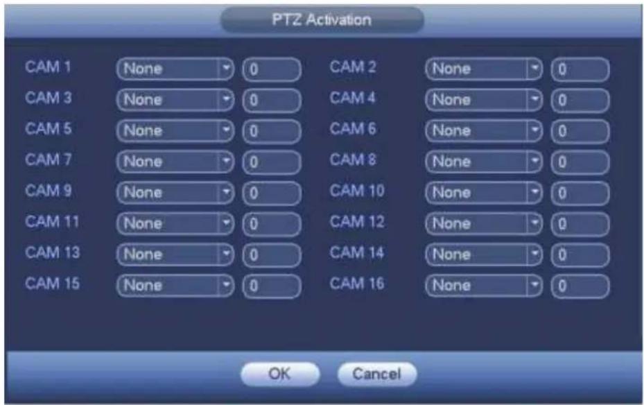
text_image
PTZ Activation CAM 1 None 0 CAM 2 None 0 CAM 3 None 0 CAM 4 None 0 CAM 5 None 0 CAM 6 None 0 CAM 7 None 0 CAM 8 None 0 CAM 9 None 0 CAM 10 None 0 CAM 11 None 0 CAM 12 None 0 CAM 13 None 0 CAM 14 None 0 CAM 15 None 0 CAM 16 None 0 OK CancelFigure 4-99
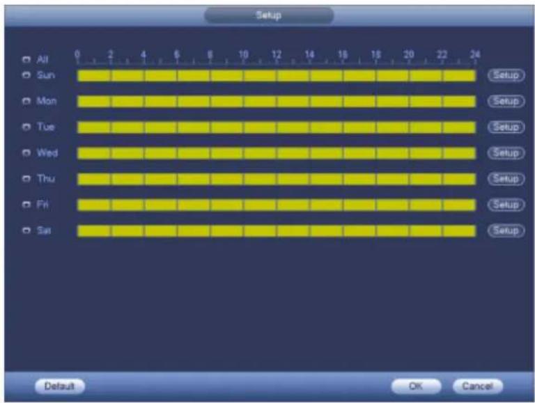
text_image
Setup All 0 2 4 6 8 10 12 14 16 18 20 22 24 Sun Mon Tue Wed Thu Fri Sat Setup Setup Setup Setup Setup Setup Default OK CancelFigure 4-100
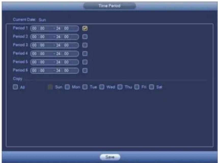
text_image
Time Period Current Date: Sun Period 1 00:00 -24:00 Period 2 00:00 -24:00 Period 3 00:00 -24:00 Period 4 00:00 -24:00 Period 5 00:00 -24:00 Period 6 00:00 -24:00 Copy All Sun Mon Tue Wed Thu Fri Sat SaveFigure 4-101
4.13.2.2 Intrusion (Cross warning zone) (Optional)
Please make sure you are connecting to the smart network camera, otherwise you can not use IVS function!
System generates an alarm once there is any object entering or exiting the zone in the specified direction. From main menu->Setting->Event->IVS->Intrusion, the intrusion interface is shown as below. See Figure 4-102.
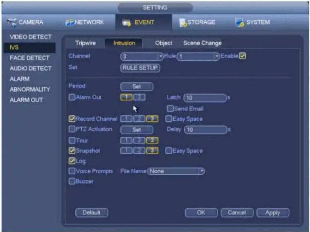
text_image
SETTING CAMERA NETWORK EVENT STORAGE SYSTEM VIDEO DETECT IVS FACE DETECT AUDIO DETECT ALARM ABNORMALITY ALARM OUT Tripwire Intrusion Object Scene Change Channel 3 Rule 1 Enable Set RULE SETUP Period Set Alarm Out 1 2 Latch 10 s Send Email Record Channel 1 2 3 Easy Space PTZ Activation Set Delay 10 s Tour 1 2 3 Easy Space Snapshot 1 2 3 Log Voice Prompts File Name None Buzzer Default OK Cancel ApplyFigure 4-102
Check the enable box to enable intrusion function.
Click Rule setup to draw the zone. See Figure 4-103.
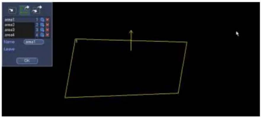
text_image
area1: 1 area2: 2 area3: 3 area4: 4 Name: area1 Leave: OKFigure 4-103
Select SN (Area1/2/3/4) and direction, and then input customized rule name.
● Area1/2/3/4: System supports four zones. Each SN stands for one zone.

- Direction (☐): System can generate an alarm once there is any object enter/exit (Or both) the zone.
Now you can draw a rule. Left click mouse to draw a line first and then right click mouse to draw another line until you draw a rectangle, you can right click mouse to exit.
Click Ok to complete the rule setup.
Tips
Click to delete the corresponding rule.
You can refer to the chapter 4.13.2.1 to set parameters.
4.13.2.3 Object Detect (Optional)
- Please make sure you are connecting to the smart network camera, otherwise you can not use IVS function!
- For the same channel, the object detect and the intrusion can not be valid at the same time.
System generates an alarm when the object missing/abandoned object alarm occurs.
From main menu->Setting->Event->IVS->Object, the object interface is shown as below. See Figure 4-104.
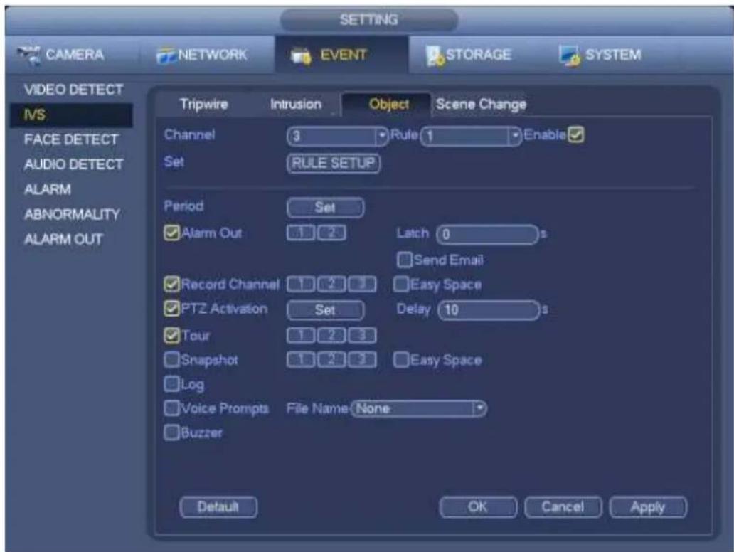
text_image
SETTING CAMERA NETWORK EVENT STORAGE SYSTEM VIDEO DETECT IVS FACE DETECT AUDIO DETECT ALARM ABNORMALITY ALARM OUT Tripwire Intrusion Object Scene Change Channel 3 Rule 1 Enable Set RULE SETUP Period Set Alarm Out 1 2 Latch 0 s Send Email Record Channel 1 2 3 Easy Space PTZ Activation Set Delay 10 s Tour 1 2 3 Snapshot 1 2 3 Easy Space Log Voice Prompts File Name None Buzzer Default OK Cancel ApplyFigure 4-104
Check the enable box to enable object detect function.
Click Rule setup to draw the rule.
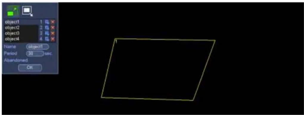
text_image
object1 1 object2 2 object3 3 object4 4 Name object1 Period 30 sec Abandoned OKFigure 4-105
Select SN (object1/2/3/4) and direction, and then input customized rule name.
- Object1/2/3/4: System supports four zones. Each SN stands for one zone.
- Direction (/). For icon, system can generate an alarm once the object left in the
one for the specified time.. For icon, system can generate an alarm once the object is out of the zone for the specified time.
- Period: It refers to the object in/out the zone time.
Now you can draw a rule. Left click mouse to draw a line, until you draw a rectangle, you can right click mouse.
Click Ok to complete the rule setup.
Tips
Click ☒ to delete the corresponding rule.
You can refer to the chapter 4.13.2.1 to set parameters.
4.13.2.4 Scene Change (Optional)
Please make sure you are connecting to the smart network camera, otherwise you can not use IVS function!
When the detected scene changes, system can generate an alarm.
From main menu->Setting->Event->IVS->Scene change, the interface is shown as in Figure 4-106.
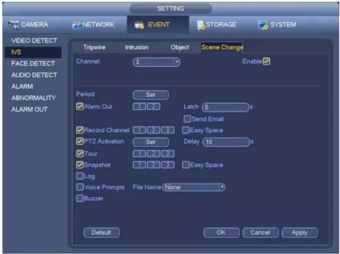
text_image
SETTING CAMERA NETWORK EVENT STORAGE SYSTEM VIDEO DETECT IVS FACE DETECT AUDIO DETECT ALARM ABNORMALITY ALARM OUT Tripwire Intrusion Object Scene Change Channel 3 Enable Period Set ✓ Alarm Out 1 2 Latch 0 s Send Email ✓ Record Channel 1 2 3 Easy Space ✓ PTZ Activation Set Delay 10 s ✓ Tour 1 2 3 ✓ Snapshot 1 2 3 Easy Space ✓ Log ✓ Voice Prompts File Name None ✓ Buzzer Default OK Cancel ApplyFigure 4-106
You can refer to the chapter 4.13.2.1 to set parameters.
4.13.3 Face Detect (Optional)

Please make sure you are connecting to the smart network camera, otherwise you can not
use IVS function!
When camera detects human face, system can generate an alarm.
From main menu->Setting->Event->Face detect, the interface is shown as in Figure 4-107.
● Face ROI: Check the box here, system can enhance the human face display pane.
- Log: Check the box here, system can record face detect log.
You can refer to the chapter 4.13.2.1 t to set other parameters.
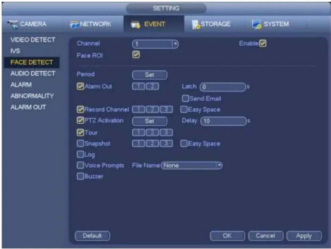
text_image
CAMERA NETWORK EVENT STORAGE SYSTEM VIDEO DETECT IVS FACE DETECT AUDIO DETECT ALARM ABNORMALITY ALARM OUT Channel 1 Enable ✓ Face ROI ✓ Period Set ✓ Alarm Out 1 2 Latch 0 s Send Email ✓ Record Channel 1 2 3 Easy Space ✓ PTZ Activation Set Delay 10 s ✓ Tour 1 2 3 ✓ Snapshot 1 2 3 Easy Space Log ✓ Voice Prompts File Name None ✓ Buzzer Default OK Cancel ApplyFigure 4-107
4.13.4 Audio Detect (Optional)

Please make sure you are connecting to the smart network camera, otherwise you can not
use IVS function!
System can generate an alarm once it detect the audio input is abnormal or audio volume changes. From main menu->Setting->Event->Audio detect, you can see an interface shown as in Figure 4-108.
- Input abnormal: Check the box here, system can generate an alarm once the audio input is abnormal.
- Intensity change: Check the box here, system can generate an alarm once the audio volume becomes strong.
- Sensitivity: It refers to the audio recognition sensitivity. The higher the value is, the higher the sensitivity is.
@ahua
- Threshold: It is to set intensity change threshold. The smaller the value is, the higher the sensitivity is.
- Log: Check the box here, system can record audio detect alarm log. You can refer to the chapter 4.13.2.1 t to set other parameters.
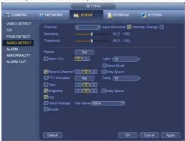
text_image
CAMERA NETWORK EVENT STORAGE SYSTEM VIDEO DETECT N/S FACE DETECT AUDIO DETECT ALARM ABNORMALITY ALARM OUT Channel 2 Input Abnormal Intensity Change Sensitivity 50 (1 - 100) Threshold 50 (1 - 100) Period Set Alarm Out Latch 10 Send Email Record Channel Easy Space PTZ Activation Delay 10 Tour 3.7.2.1 Snapshot Easy Space Tag Voice Promptp File Name: None Bluzzer Default OK Cancel ApplyFigure 4-108
4.13.5 Alarm output
From Main menu->Setting->Event->Alarm output, you can see an interface shown as in Figure 4-109. Here is for you to set proper alarm output (Auto/manual/stop). Click OK button of the alarm reset, you can clear all alarm output status.
Figure 4-109
Please highlight icon to select the corresponding alarm output.
After all the setups please click OK button, system goes back to the previous menu.
4.13.6 Alarm Setup
In the main menu, from Setting->Event->Alarm, you can see alarm setup interface.
● Alarm in: Here is for you to select channel number.
In the main menu, from Setting->Event->Alarm, you can see alarm setup interface. See Figure 4-110.
There are four alarm types. See Figure 4-110 to Figure 4-113.
Local alarm: The alarm signal system detects from the alarm input port.
✨ Network alarm: It is the alarm signal from the network.
✿ IPC external alarm: It is the on-off alarm signal from the front-end device and can activate the local HNVR.
IPC offline alarm: Once you select this item, system can generate an alarm when the front-end IPC disconnects with the local HNVR. The alarm can activate record, PTZ, snap and etc. The alarm can last until the IPC and the HNVR connection resumes.
Important
- If it is your first time to boot up the device, the disconnection status of the front-end network camera will not be regarded as offline. After one successfully connection, all the disconnection events will be regarded as IPC offline event.
-
When IPC offline alarm occurs, the record and snapshot function of digital channel is null.
-
Enable: Please you need to highlight this button to enable current function.
● Type: normal open or normal close. - Period: Click set button, you can see an interface is shown as in Figure 4-115. There are two ways for you to set periods. There are max 6 periods in one day. There are four record types: regular, motion detection (MD), Alarm, MD & alarm.
In Figure 4-115, Select icon of several dates, all checked items can be edited together.


to delete a record type from one period.
In Figure 4-115. Click button after one date or a holiday, you can see an interface shown as in Figure 4-116. There are four record types: regular, motion detection (MD), Alarm, MD & alarm.
- PTZ activation: When an alarm occurred, system can activate the PTZ operation. The PTZ activation lasts an anti-dither period. See Figure 4-114.
- Anti-dither: Here you can set anti-dither time. The value ranges from 5 to 600s. The anti-dither time refers to the alarm signal lasts time. It can be seen as the alarm signal activation stays such as the buzzer, tour, PTZ activation, snapshot, channel record. The stay time here does not include the latch time. During the alarm process, the alarm signal can begin an anti-dither time if system detects the local alarm again. The screen prompt, alarm upload, email and etc will not be activated. For example, if you set the anti-dither time as 10 second, you can see the each activation may last 10s if the local alarm is activated. During the process, if system detects another local alarm signal at the fifth second, the buzzer, tour, PTZ activation, snapshot, record channel will begin another 10s while the
screen prompt, alarm upload, email will not be activated again. After 10s, if system detects another alarm signal, it can generate an alarm since the anti-dither time is out.
- Alarm output: The number here is the device alarm output port. You can select the corresponding ports(s) so that system can activate the corresponding alarm device(s) when an alarm occurred.
- Latch: When the anti-dither time ended, the channel alarm you select in the alarm output may last the specified period. The value ranges from 1 to 300 seconds. This function is not for other alarm activation operations. The latch is still valid even you disable the alarm event function directly.
● Show message: System can pop up a message to alarm you in the local host screen if you enabled this function.
- Alarm upload: System can upload the alarm signal to the network (including alarm centre and the WEB) if you enabled current function. System only uploads the alarm channel status. You can go to the WEB and then go to the Alarm interface to set alarm event and alarm operation. Please go to the Network interface to set alarm centre information.
- Send email: System can send out the alarm signal via the email to alert you when alarm occurs. Once you enable the snap function, system can also send out an image as the attachment. Please go to the Main Menu->Setting ->Network->Email interface to set.
- Record channel: you can select proper channel to record alarm video (Multiple choices).
You need to set alarm record mode as Schedule in Record interface (Main Menu->Advanced->Record). Please note the manual record has the highest priority. System record all the time no matter there is an alarm or not if you select Manual mode.
Now you can go to the Schedule interface (Main Menu->Setting->Schedule) to set the record type, corresponding channel number, week and date. You can select the record type: Regular/MD/Alarm/MD&Alarm. Please note, you can not select the MD&Alarm and MD(or Alarm) at the same time.
Now you can go to the Encode interface to select the alarm record and set the encode parameter (Main Menu->Setting->Encode).
Finally, you can set the alarm input as the local alarm and then select the record channel. The select channel begins alarm record when an alarm occurred. Please note system begins the alarm record instead of the MD record if the local alarm and MD event occurred at the same time.
- Tour: Here you can enable tour function when an alarm occurs. System supports 1/8-window tour. Please go to chapter4.7.4.2 Display for tour interval setup. Please note the tour setup here has higher priority than the tour setup you set in the Display interface. Once there two tours are both enabled, system can enable the alarm tour as you set here when an alarm occurred. If there is no alarm, system implements the tour setup in the Display interface.
- Snapshot: You can enable this function to snapshot image when an alarm occurs.
- Buzzer: Highlight the icon to enable this function. The buzzer beeps when an alarm occurs.
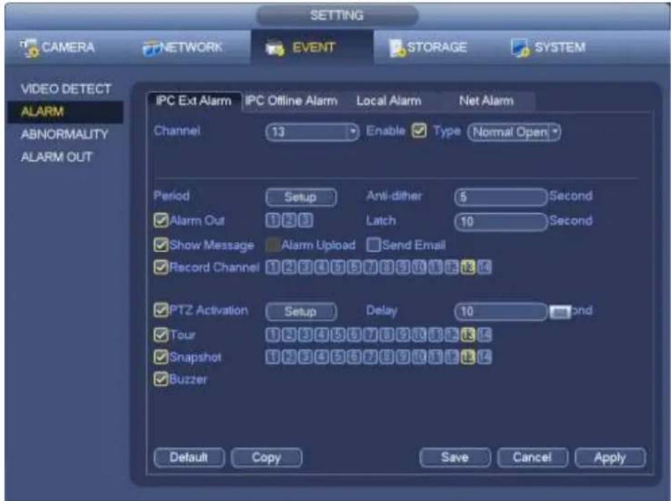
text_image
CAMERA NETWORK EVENT STORAGE SYSTEM VIDEO DETECT ALARM ABNORMALITY ALARM OUT IPC Ext Alarm IPC Offline Alarm Local Alarm Net Alarm Channel 13 Enable Type Normal Open Period Setup Anti-dither 5 Second Alarm Out 123 Latch 10 Second Show Message Alarm Upload Send Email Record Channel 1234567891011121314 PTZ Activation Setup Delay 10 Second Tour 1234567891011121314 Snapshot 1234567891011121314 Buzzer Default Copy Save Cancel ApplyFigure 4-110
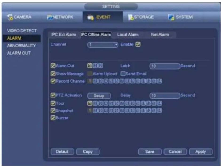
text_image
SETTING CAMERA NETWORK EVENT STORAGE SYSTEM VIDEO DETECT ALARM ABNORMALITY ALARM OUT IPC Ext Alarm IPC Offline Alarm Local Alarm Net Alarm Channel 1 Enable ✓ Alarm Out 1 2 3 Latch 10 Second ✓ Show Message Alarm Upload Send Email ✓ Record Channel 1 2 3 4 5 6 7 8 9 10 11 12 ✓ PTZ Activation Setup Delay 10 Second ✓ Tour 1 2 3 4 5 6 7 8 9 10 11 12 ✓ Snapshot 1 2 3 4 5 6 7 8 9 10 11 12 ✓ Buzzer Default Copy Save Cancel ApplyFigure 4-111
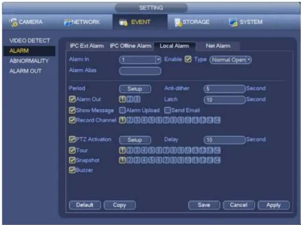
text_image
SETTING CAMERA NETWORK EVENT STORAGE SYSTEM VIDEO DETECT ALARM ABNORMALITY ALARM OUT IPC Ext Alarm IPC Offline Alarm Local Alarm Net Alarm Alarm In 1 Enable ✓ Type Normal Open Alarm Alias Period Setup Anti-dither 5 Second ✓ Alarm Out 1 2 3 Latch 10 Second ✓ Show Message ✓ Alarm Upload ✓ Send Email ✓ Record Channel 1 2 3 4 5 6 7 8 9 10 11 12 13 14 ✓ PTZ Activation Setup Delay 10 Second ✓ Tour 1 2 3 4 5 6 7 8 9 10 11 12 13 ✓ Snapshot 1 2 3 4 5 6 7 8 9 10 11 12 13 ✓ Buzzer Default Copy Save Cancel ApplyFigure 4-112
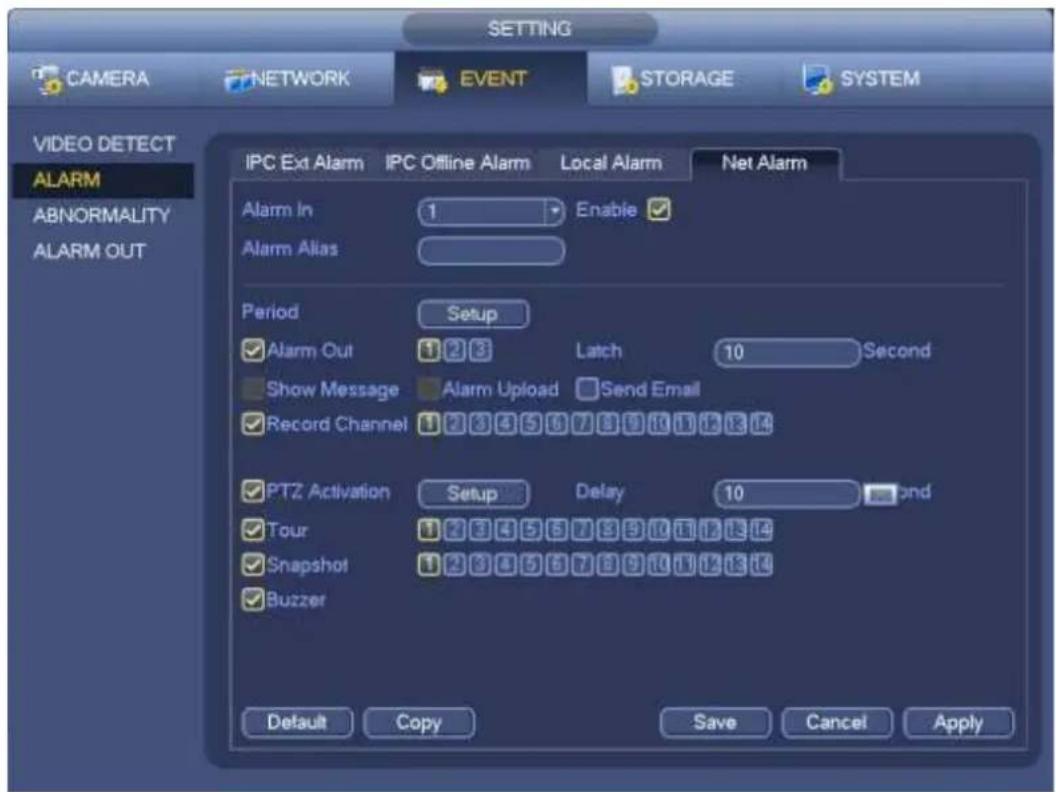
text_image
SETTING CAMERA NETWORK EVENT STORAGE SYSTEM VIDEO DETECT ALARM ABNORMALITY ALARM OUT IPC Ext Alarm IPC Offline Alarm Local Alarm Net Alarm Alarm In 1 Enable Alarm Alias Period Setup ✓ Alarm Out 1 2 3 Latch 10 Second Show Message Alarm Upload Send Email ✓ Record Channel 1 2 3 4 5 6 7 8 9 10 11 12 13 14 ✓ PTZ Activation Setup Delay 10OND ✓ Tour 1 2 3 4 5 6 7 8 9 10 11 12 13 14 ✓ Snapshot 1 2 3 4 5 6 7 8 9 10 11 12 13 14 ✓ Buzzer Default Copy Save Cancel ApplyFigure 4-113
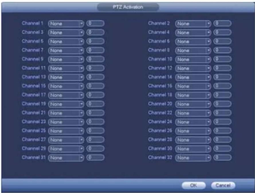
text_image
PTZ Activation Channel 1 None 0 Channel 2 None 0 Channel 3 None 0 Channel 4 None 0 Channel 5 None 0 Channel 6 None 0 Channel 7 None 0 Channel 8 None 0 Channel 9 None 0 Channel 10 None 0 Channel 11 None 0 Channel 12 None 0 Channel 13 None 0 Channel 14 None 0 Channel 15 None 0 Channel 16 None 0 Channel 17 None 0 Channel 18 None 0 Channel 19 None 0 Channel 20 None 0 Channel 21 None 0 Channel 22 None 0 Channel 23 None 0 Channel 24 None 0 Channel 25 None 0 Channel 26 None 0 Channel 27 None 0 Channel 28 None 0 Channel 29 None 0 Channel 30 None 0 Channel 31 None 0 Channel 32 None 0 OK CancelFigure 4-114
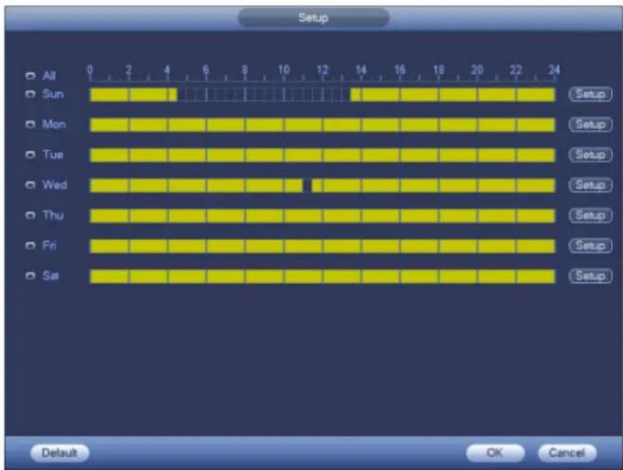
text_image
Setup All Sun Mon Tue Wed Thu Fri Sat 0 2 4 6 8 10 12 14 16 18 20 22 24 Setup Setup Setup Setup Setup Setup Setup Setup Default OK CancelFigure 4-115
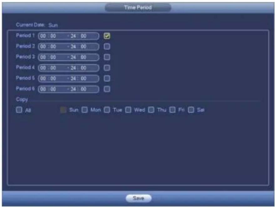
text_image
Time Period Current Date: Sun Period 1 00 : 00 - 24 00 Period 2 00 : 00 - 24 00 Period 3 00 : 00 - 24 00 Period 4 00 : 00 - 24 00 Period 5 00 : 00 - 24 00 Period 6 00 : 00 - 24 00 Copy All Sun Mon Tue Wed Thu Fri Sat SaveFigure 4-116
Please highlight icon ☐ to select the corresponding function. After setting all the setups please click save button, system goes back to the previous menu.
4.13.7 Abnormality
There are two types: Disk/Network.
◇ Disk: Disk error, no disk, no space. See Figure 4-117 and Figure 4-118.
Network: Disconnection, IP conflict, MAC conflict. See Figure 4-119.
- Alarm output: Please select alarm activation output port (multiple choices).
● Less than: System can alarm you when the HDD space is less than the threshold you set here (For HDD no space type only). - Latch: Here you can set corresponding delaying time. The value ranges from 1s-300s. System automatically delays specified seconds in turning off alarm and activated output after external alarm cancelled.
● Show message: system can pop up the message in the local screen to alert you when alarm occurs. - Alarm upload: System can upload the alarm signal to the network (including alarm centre) if you enabled current function. For disconnection event, IP conflict event and MAC conflict event, this function is null.
- Send email: System can send out email to alert you when alarm occurs.
- Buzzer: Highlight the icon to enable this function. The buzzer beeps when an alarm occurs.
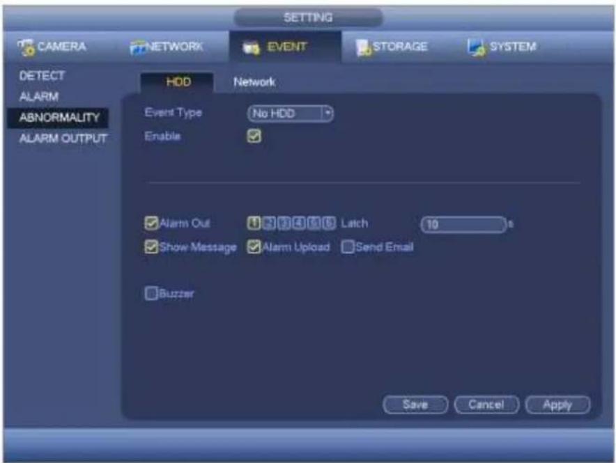
text_image
SETTING CAMERA NETWORK EVENT STORAGE SYSTEM DETECT ALARM ABNORMALITY ALARM OUTPUT HDD Network Event Type No HDD Enable ✓ Alarm Out ✓ Show Message ✓ Alarm Upload ✓ Buzzer Latch 10 s Send Email Save Cancel ApplyFigure 4-117
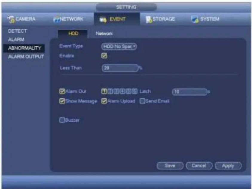
text_image
SETTING CAMERA NETWORK EVENT STORAGE SYSTEM DETECT ALARM ABNORMALITY ALARM OUTPUT HDD Network Event Type HDD No Spas Enable Less Than 20 ✓ Alarm Out ✓ Latch 10 ✓ Show Message ✓ Alarm Upload Send Email ✓ Buzzer Save Cancel ApplyFigure 4-118
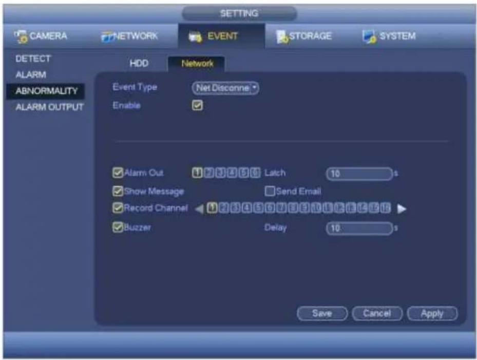
text_image
SETTING CAMERA NETWORK EVENT STORAGE SYSTEM DETECT ALARM ABNORMALITY ALARM OUTPUT HDD Network Event Type Net Disconne Enable ✓ Alarm Out Latch 10 s ✓ Show Message Send Email ✓ Record Channel Delay 10 s ✓ Buzzer Save Cancel ApplyFigure 4-119
4.14 Network
4.14.1.1 TCP/IP
The single network adapter interface is shown as in Figure 4-120 and the dual network adapters interface is shown as in Figure 4-121.
● Network Mode : Includes multiple access, fault tolerance, and load balancing
Multiple-address mode: eth0 and eth1 operate separately. You can use the services such as HTTP, RTP service via etho0 or the eth1. Usually you need to set one default card (default setup is etho) to request the auto network service form the device-end such as DHCP, email, FTP and etc. In multiple-address mode, system network status is shown as offline once one card is offline.
Network fault-tolerance: In this mode, device uses bond0 to communicate with the external devices. You can focus on one host IP address. At the same time, you need to set one master card. Usually there is only one running card (master card). System can enable alternate card when the master card is malfunction. The system is shown as offline once these two cards are both offline. Please note these two cards shall be in the same LAN.
Load balance: In this mode, device uses bond0 to communicate with the external device. The eth0 and eth1 are both working now and bearing the network load. Their network load are general the same. The system is shown as offline once these two cards are both offline. Please note these two cards shall be in the same LAN.
- Default Network Card: Please select eth0/eth1/bond0(optional) after enable multiple-access function
● Main Network Card: Please select eth0/eth1 (optional).after enable multiple access function.
Note: The dual-Ethernet port series support the above three configurations and supports functions as multiple-access, fault-tolerance and load balancing.
- IP Version: There are two options: IPv4 and IPv6. Right now, system supports these two IP address format and you can access via them.
- MAC address: The host in the LAN can get a unique MAC address. It is for you to access in the LAN. It is read-only.
- IP address: Here you can use up/down button (▲▼) or input the corresponding number to input IP address. Then you can set the corresponding subnet mask the default gateway.
- Default gateway: Here you can input the default gateway. Please note system needs to check the validity of all IPv6 addresses. The IP address and the default gateway shall be in the same IP section. That is to say, the specified length of the subnet prefix shall have the same string.
- DHCP: It is to auto search IP. When enable DHCP function, you can not modify IP/Subnet mask /Gateway. These values are from DHCP function. If you have not enabled DHCP function, IP/Subnet mask/Gateway display as zero. You need to disable DHCP function to view current IP information. Besides, when PPPoE is operating, you can not modify IP/Subnet mask /Gateway.
- MTU: It is to set MTU value of the network adapter. The value ranges from 1280-7200 bytes. The default setup is 1500 bytes. Please note MTU modification may result in network adapter reboot and network becomes off. That is to say, MTU modification can affect current network service. System may pop up dialog box for you to confirm setup when you want to change MTU setup. Click OK button to confirm current reboot, or you can click Cancel button to terminate current modification. Before the modification, you can check the MTU of the gateway; the MTU of the NVR shall be the same as or is lower than the MTU of the gateway. In this way, you can reduce packets and enhance network transmission efficiency.
The following MTU value is for reference only.
1500: Ethernet information packet max value and it is also the default value. It is the typical setup when there is no PPPoE or VPN. It is the default setup of some router, switch or the network adapter.
◆ 1492: Recommend value for PPPoE.
1468: Recommend value for DHCP.
- Preferred DNS server: DNS server IP address.
- Alternate DNS server: DNS server alternate address.
● Transfer mode: Here you can select the priority between fluency/video qualities.
● LAN download: System can process the downloaded data first if you enable this function. The download speed is 1.5X or 2.0X of the normal speed.
● LAN download: System can process the downloaded data first if you enable this function. The download speed is 1.5X or 2.0X of the normal speed.
After completing all the setups please click save button, system goes back to the previous menu.
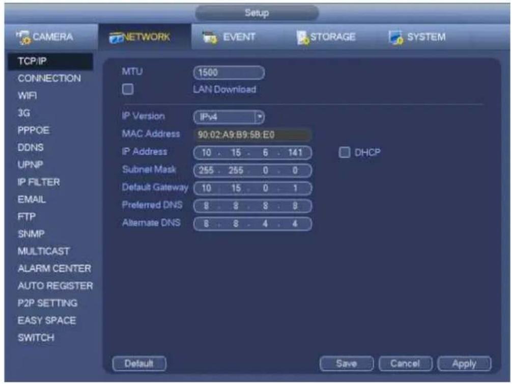
text_image
Setup CAMERA NETWORK EVENT STORAGE SYSTEM TCP/IP CONNECTION WIFI 3G PPPOE DDNS UPNP IP FILTER EMAIL FTP SNMP MULTICAST ALARM CENTER AUTO REGISTER P2P SETTING EASY SPACE SWITCH MTU 1500 LAN Download IP Version IPv4 MAC Address 90:02:A9:B9:5B:E0 IP Address 10 . 15 . 6 . 141 Subnet Mask 255 . 265 . 0 . 0 Default Gateway 10 . 15 . 0 . 1 Preferred DNS 8 . 8 . 8 . 8 Alternate DNS 8 . 8 . 4 . 4 DHCP Default Save Cancel ApplyFigure 4-120
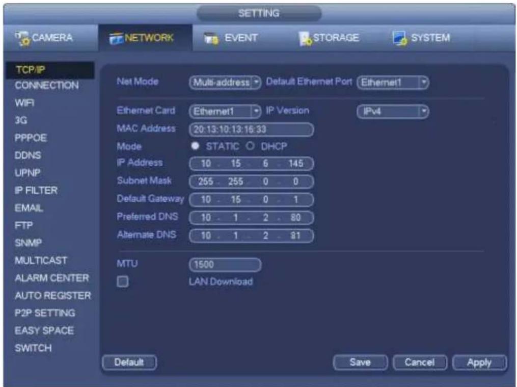
text_image
SETTING CAMERA NETWORK EVENT STORAGE SYSTEM TCP/IP CONNECTION WIFI 3G PPPOE DDNS UPNP IP FILTER EMAIL FTP SNMP MULTICAST ALARM CENTER AUTO REGISTER P2P SETTING EASY SPACE SWITCH Net Mode Multi-address Default Ethernet Port Ethernet1 Ethernet Card Ethernet1 IP Version IPv4 MAC Address 20:13:10:13:16:33 Mode STATIC DHCP IP Address 10 . 15 . 6 . 145 Subnet Mask 255 . 255 . 0 . 0 Default Gateway 10 . 15 . 0 . 1 Preferred DNS 10 . 1 . 2 . 80 Alternate DNS 10 . 1 . 2 . 81 MTU 1500 LAN Download Default Save Cancel ApplyFigure 4-121
4.14.1.2 Connection
The connection setup interface is shown as in Figure 4-122.
● Max connection: system support maximal 128 users. 0 means there is no connection limit.
- TCP port: Default value is 37777.
- UDP port: Default value is 37778.
- HTTP port: Default value is 80.
- HTTPS port: Default value is 443.
- RTSP port: Default value is 554.
Important: System needs to reboot after you changed and saved any setup of the above four ports. Please make sure the port values here do not conflict.
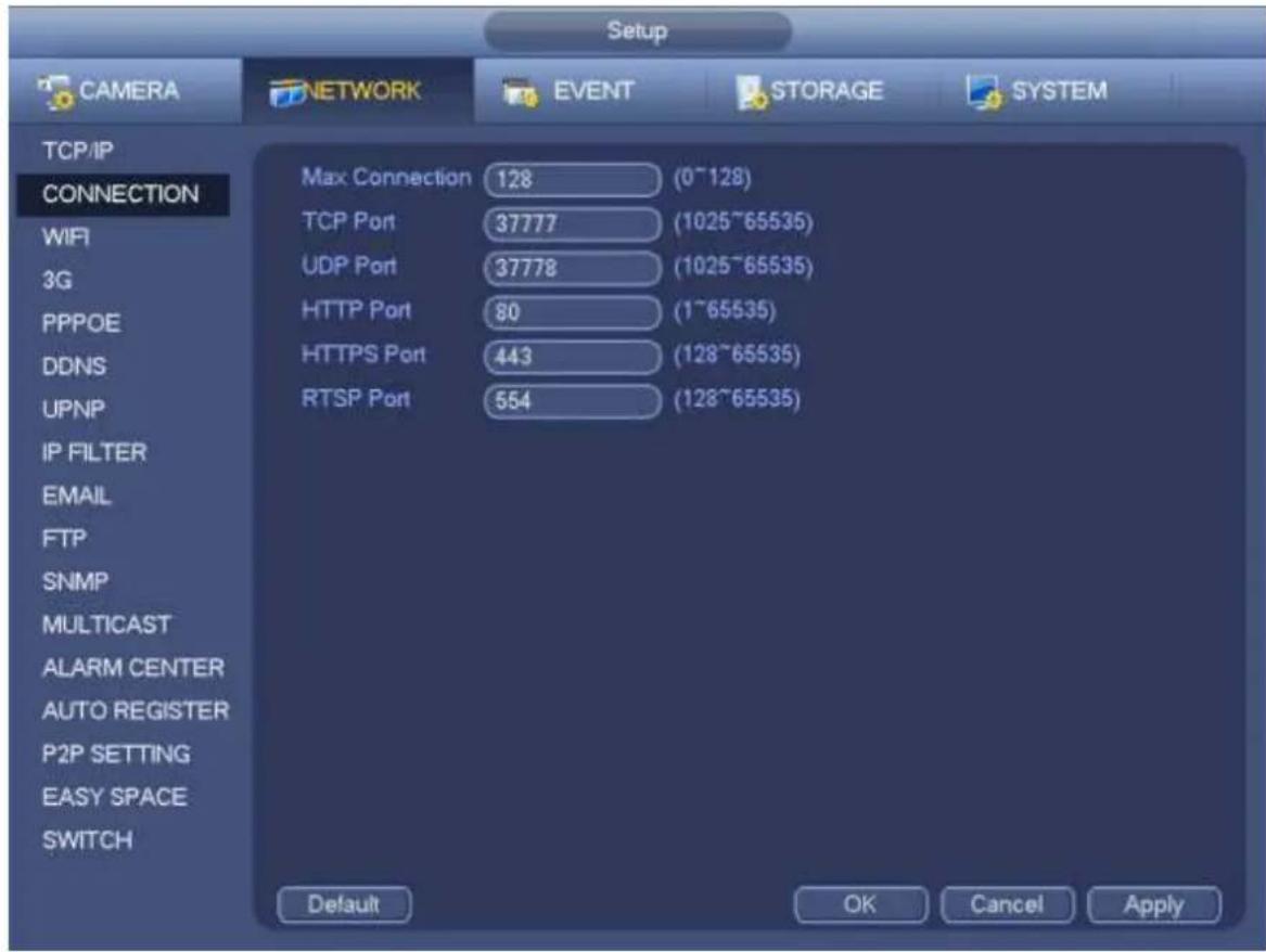
text_image
Setup CAMERA NETWORK EVENT STORAGE SYSTEM TCP/IP CONNECTION WiFi 3G PPPOE DDNS UPNP IP FILTER EMAIL FTP SNMP MULTICAST ALARM CENTER AUTO REGISTER P2P SETTING EASY SPACE SWITCH Max Connection 128 (0~128) TCP Port 37777 (1025~65535) UDP Port 37778 (1025~65535) HTTP Port 80 (1~65535) HTTPS Port 443 (128~65535) RTSP Port 554 (128~65535) Default OK Cancel ApplyFigure 4-122
4.14.1.3 WIFI AP
Note
This function is for some series product only.
The WIFI AP interface is shown as below. See Figure 4-123. Here you can set WIFI hotspot, so that the network camera can use the hotspot to connect to the network.
- SSID: It is to set SSID name. You can use this name to search the device.
- Password: It is to set SSID password. You can use this password to connect to the network.
- Authentication mode: Select authentication from the dropdown list.
- Encrypt type: Select encryption type from the dropdown list.
- Start IP/End IP: Input start IP and end IP. The NVR can allocate the IP address in the range you specified here.
- WPS: Click WPS button to enable WPS function. After the network camera enabled this function, it can automatically connect to the network.
- Remote device: In the list, you can view the network camera(s) that connected to the NVR. It includes signal intensity, IP, MAC address, bit rate, channel number, type, status and etc.
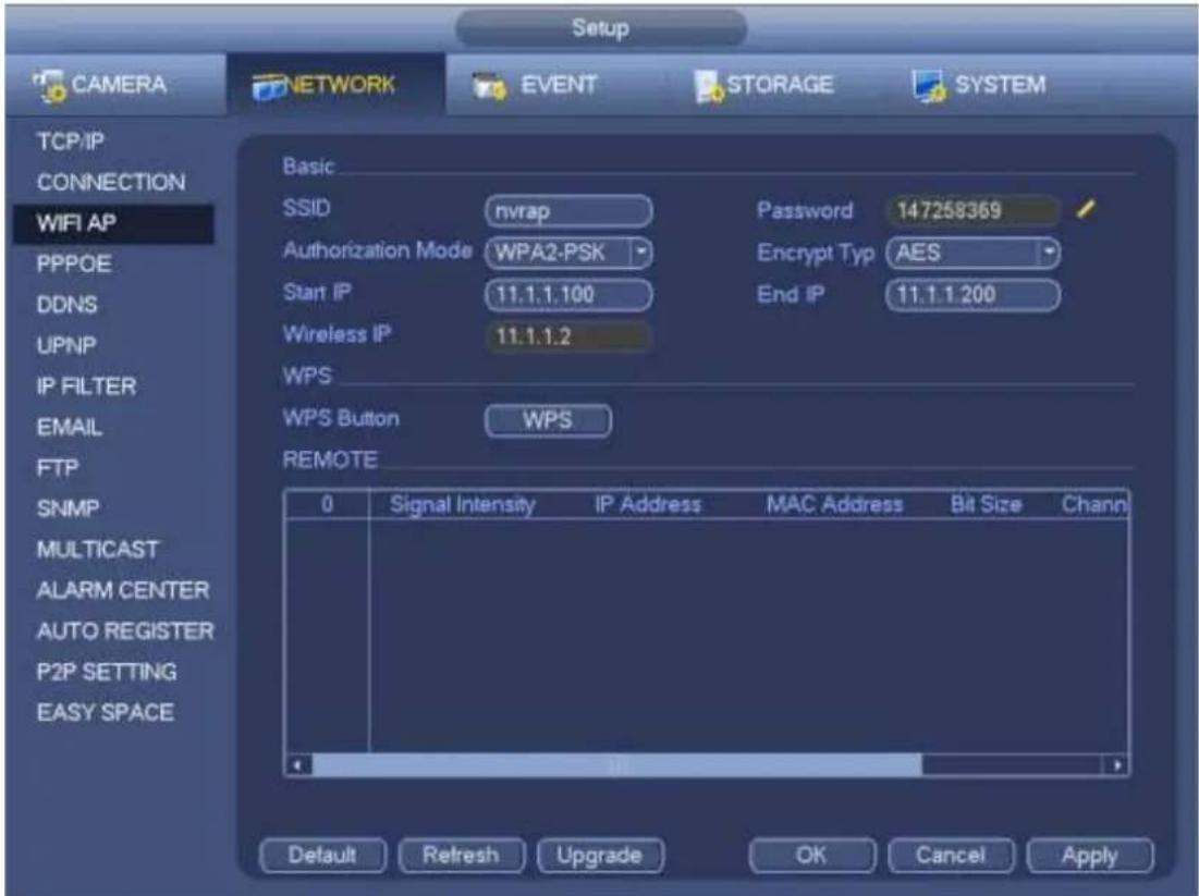
text_image
Setup CAMERA NETWORK EVENT STORAGE SYSTEM TCP/IP CONNECTION WIFI AP PPPOE DDNS UPNP IP FILTER EMAIL FTP SNMP MULTICAST ALARM CENTER AUTO REGISTER P2P SETTING EASY SPACE Basic SSID nvrap Password 147258369 Authorization Mode WPA2-PSK Encrypt Typ AES Start IP 11.1.1.100 End IP 11.1.1.200 Wireless IP 11.1.1.2 WPS WPS Button WPS REMOTE 0 Signal Intensity IP Address MAC Address Bit Size Chann Default Refresh Upgrade OK Cancel ApplyFigure 4-123
4.14.1.4 WIFI
The WIFI interface is shown as below. See Figure 4-124.
- Enable: Check the box here to enable WIFI function.
- Refresh: You can click it to search the hotspot list again. It can automatically add the information such as the password if you have set it before.
- Disconnect: Here you can click it to turn off the connection.
- Connect: Here you can click it to connect to the hotspot. System needs to turn off current connection and then connect to a new hotspot if there is connection of you selected one.
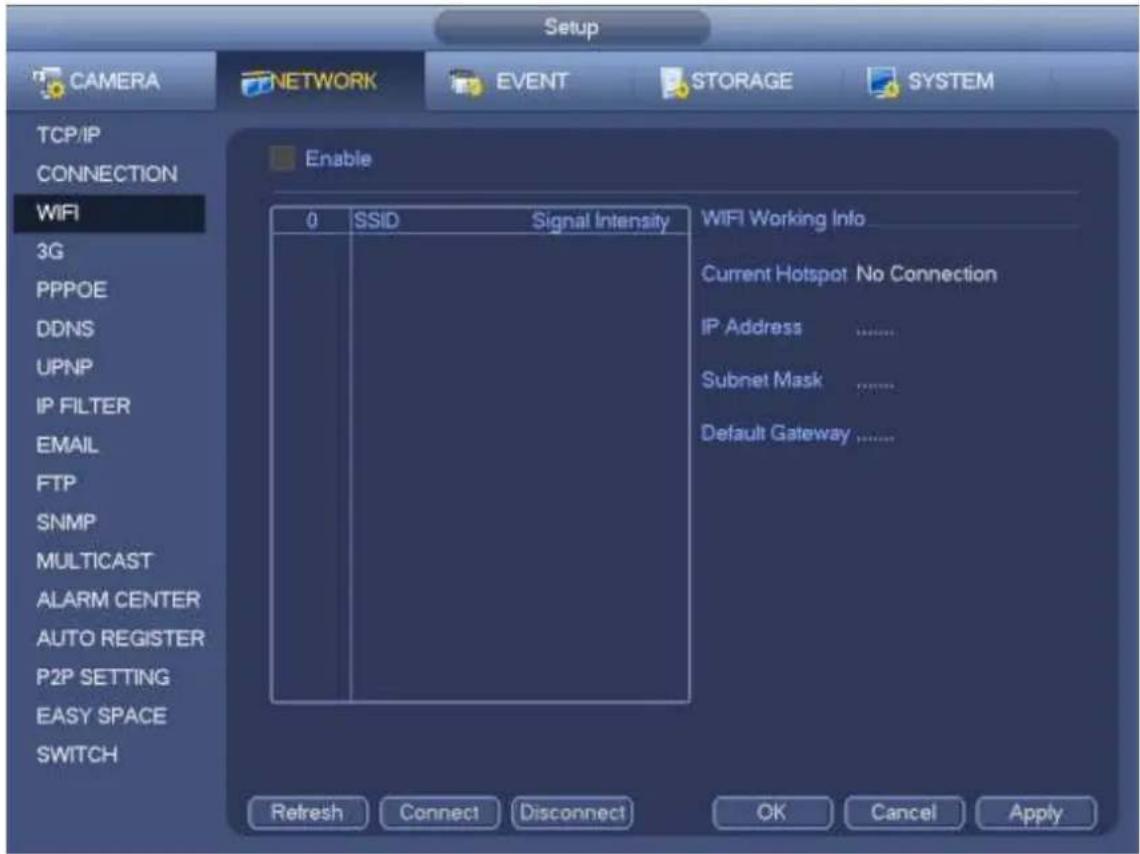
text_image
Setup CAMERA NETWORK EVENT STORAGE SYSTEM TCP/IP CONNECTION WiFi 3G PPPOE DDNS UPNP IP FILTER EMAIL FTP SNMP MULTICAST ALARM CENTER AUTO REGISTER P2P SETTING EASY SPACE SWITCH Enable 0 SSID Signal Intensity WIFI Working Info Current Hotspot No Connection IP Address ...... Subnet Mask ...... Default Gateway ...... Refresh Connect Disconnect OK Cancel ApplyFigure 4-124
● WIFI working status: Here you can view current connection status.
Please note:
- After successful connection, you can see WIFI connection icon at the top right corner of the preview interface.
- When the hotspot verification type is WEP, system displays as AUTO since the device can not detect its encryption type.
- System does not support verification type WPA and WPA2. The display may become abnormal for the verification type and encryption type.
After device successfully connected to the WIFI, you can view the hotspot name, IP address, subnet mask, default gateway and etc. Right now system support TOTOLINK_N2200UP module.
4.14.1.5 3G
3G setup interface is shown as below. See Figure 4-125.
Please refer to the following contents for the parameter information.
- Pane 1: Display 3G signal intensity after you enabled 3G function.
- Pane 2: Display 3G module configuration information after you enabled 3G function.
- Pane 3: Display 3G module status information after you enabled 3G function.
It is to display current wireless network signal intensity such as EVDO, CDMA1x, WCDMA, WCDMA, EDGE and etc.
- 3G module: It is to display current wireless network adapter name.
- 3G Enable/Disable: Check the box here to enable 3G module.
-
Network type: There are various network types for different 3G network modules. You can select according to your requirements.
-
APN: It is the wireless connection server. It is to set you access the wireless network via which method.
● AUTH: It is the authentication mode. It supports PAP/CHAP. - Dial number: Please input 3G network dialup number you got from your ISP.
- User name: It is the user name for you to login the 3G network.
- Password: It is the password for you to login the 3G network.
- Pulse interval: You can set dialup duration. Once you disable the extra stream, the connection time begins. For example, if you input 5 seconds here, then 3G network connection period is 5 seconds. The device automatically disconnect when time is up. If there is no extra stream, 3G network connection is valid all the time. If the alive time is 0, then the 3G network connection is valid all the time.
- Dial: Here you can enable or disable 3G network connection/disconnection manually.
- 3G wireless network: Here is to display wireless network status, SIM card status, dial status. If the 3G connection is OK, then you can see the device IP address the wireless network automatically allocates.
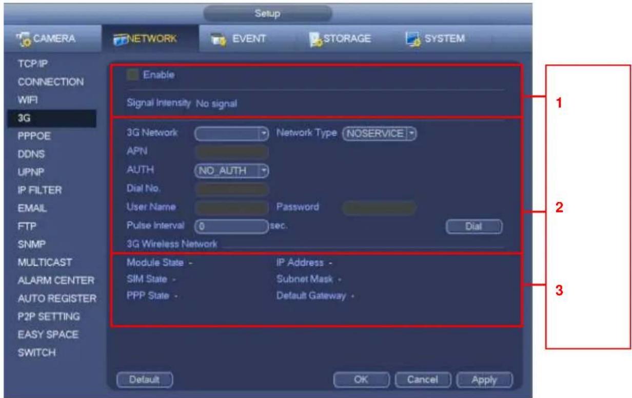
text_image
Setup CAMERA NETWORK EVENT STORAGE SYSTEM TCP/IP CONNECTION WIFI 3G PPPOE DDNS UPNP IP FILTER EMAIL FTP SNMP MULTICAST ALARM CENTER AUTO REGISTER P2P SETTING EASY SPACE SWITCH Enable Signal Intensity No signal 3G Network Network Type NOSERVICE APN AUTH NO_AUTH Dial No. User Name Password Pulse Interval 0 sec. Dial 3G Wireless Network Module State - SIM State - PPP State - IP Address - Subnet Mask - Default Gateway - OK Cancel Apply 1 2 3Figure 4-125
4.14.1.6 PPPoE
PPPoE interface is shown as in Figure 4-126.
Input "PPPoE name" and "PPPoE password" you get from your ISP (Internet service provider).
Click save button, you need to restart to activate your configuration.
After rebooting, NVR will connect to internet automatically. The IP in the PPPoE is the NVR dynamic value. You can access this IP to visit the unit.
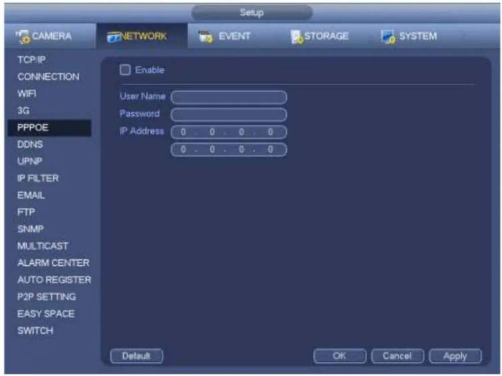
text_image
Setup CAMERA NETWORK EVENT STORAGE SYSTEM TCP/IP CONNECTION WIFI 3G PPPOE DDNS UPNP IP FILTER EMAIL FTP SNMP MULTICAST ALARM CENTER AUTO REGISTER P2P SETTING EASY SPACE SWITCH Enable User Name Password IP Address 0 . 0 . 0 . 0 0 . 0 . 0 . 0 Default OK Cancel ApplyFigure 4-126
4.14.1.7 DDNS
DDNS setup interface is shown as in Figure 4-127.
You need a PC of fixed IP in the internet and there is the DDNS software running in this PC. In other words, this PC is a DNS (domain name server).
In network DDNS, please select DDNS type and highlight enable item. And them please input your PPPoE name you get from you IPS and server IP (PC with DDNS). Click save button and then reboot system.
Click save button, system prompts for rebooting to get all setup activated.
After rebooting, open IE and input as below:
http://(DDNS server IP)/(virtual directory name)/webtest.htm
e.g.: http://10.6.2.85/NVR_DDNS/webtest.htm.)
Now you can open DDNSServer web search page.
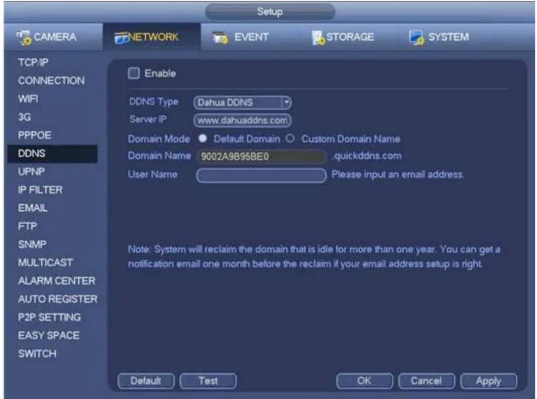
text_image
Setup CAMERA NETWORK EVENT STORAGE SYSTEM TCP/IP CONNECTION WIFI 3G PPPOE DDNS UPNP IP FILTER EMAIL FTP SNMP MULTICAST ALARM CENTER AUTO REGISTER P2P SETTING EASY SPACE SWITCH Enable DDNS Type Dahua DDNS Server IP www.dahuaddns.com Domain Mode Default Domain Custom Domain Name Domain Name 9002A9B95BE0 quickddns.com User Name Please input an email address. Note: System will reclaim the domain that is idle for more than one year. You can get a notification email one month before the reclaim if your email address setup is right. Default Test OK Cancel ApplyFigure 4-127
Please note DDNS type includes: CN99 DDNS, NO-IP DDNS, Quick DDNS, Dyndns DDNS and sysdns DDNS. All the DDNS can be valid at the same time, you can select as you requirement.
Private DDNS function shall work with special DDNS server and special Professional Surveillance Software (PSS).
Dahua DDNS and Client-end Introduction
1) Background Introduction
Device IP is not fixed if you use ADSL to login the network. The DDNS function allows you to access the NVR via the registered domain name. Besides the general DDNS, the Dahua DDNS works with the device from the manufacturer so that it can add the extension function.
2) Function Introduction
The Dahua DDNS client has the same function as other DDNS client end. It realizes the bonding of the domain name and the IP address. Right now, current DDNS server is for our own devices only. You need to refresh the bonding relationship of the domain and the IP regularly. There is no user name, password or the ID registration on the server. At the same time, each device has a default domain name (Generated by MAC address) for your option. You can also use customized valid domain name (has not registered.).
3) Operation
Before you use Dahua DDNS, you need to enable this service and set proper server address, port value and domain name.
● Server address: www.dahuaddns.com
- Port number: 80
- Domain name: There are two modes: Default domain name and customized domain name.
Except default domain name registration, you can also use customized domain name (You can input your self-defined domain name.) After successful registration, you can use domain name to login installed of
the device IP.
- User name: It is optional. You can input your commonly used email address.
Important
- Do not register frequently. The interval between two registrations shall be more than 60 seconds. Too many registration requests may result in server attack.
- System may take back the domain name that is idle for one year. You can get a notification email before the cancel operation if your email address setup is OK.
4.14.1.8 UPnP
The UPNP protocol is to establish a mapping relationship between the LAN and the WAN. Please input the router IP address in the LAN in Figure 4-120. See Figure 4-128.
- UPNP on/off : Turn on or off the UPNP function of the device.
- Status: When the UPNP is offline, it shows as "Unknown". When the UPNP works it shows "Success"
- Router LAN IP: It is the router IP in the LAN.
- WAN IP: It is the router IP in the WAN.
- Port Mapping list: The port mapping list here is the one to one relationship with the router's port mapping setting.
- List:
Service name: Defined by user.
✨ Protocol: Protocol type
Internal port: Port that has been mapped in the router.
External port: Port that has been mapped locally.
- Default: UPNP default port setting is the HTTP, TCP and UDP of the NVR.
- Add to the list: Click it to add the mapping relationship.
- Delete: Click it to remove one mapping item.
Double click one item; you can change the corresponding mapping information. See Figure 4-129.
Important:
When you are setting the router external port, please use 1024\~5000 port. Do not use well-known port 1\~255 and the system port 256\~1023 to avoid conflict.
For the TCP and UDP, please make sure the internal port and external port are the same to guarantee the proper data transmission.
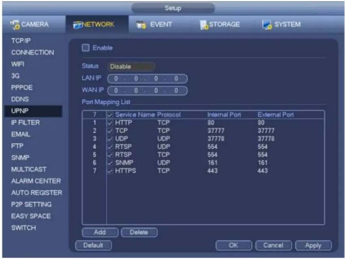
text_image
Setup CAMERA NETWORK EVENT STORAGE SYSTEM TCP/IP CONNECTION WIFI 3G PPPOE DDNS UPNP IP FILTER EMAIL FTP SNMP MULTICAST ALARM CENTER AUTO REGISTER P2P SETTING EASY SPACE SWITCH Enable Status Disable LAN IP 0 . 0 . 0 . 0 WAN IP 0 . 0 . 0 . 0 Port Mapping List 7 ✓ Service Name Protocol Internal Port External Port 1 ✓ HTTP TCP 80 80 2 ✓ TCP TCP 37777 37777 3 ✓ UDP UDP 37778 37778 4 ✓ RTSP UDP 554 554 5 ✓ RTSP TCP 554 554 6 ✓ SNMP UDP 161 161 7 ✓ HTTPS TCP 443 443 Add Delete Default OK Cancel ApplyFigure 4-128

text_image
PORT INFO Service Name HTTP Protocol TCP Internal Port 80 External Port 80 OK CancelFigure 4-129
4.14.1.9 IP Filter
IP filter interface is shown as in Figure 4-130. You can add IP in the following list. The list supports max 64 IP addresses. System supports valid address of IPv4 and IPv6. Please note system needs to check the validity of all IPv6 addresses and implement optimization.
After you enabled trusted sites function, only the IP listed below can access current NVR.
If you enable blocked sites function, the following listed IP addresses can not access current NVR.
- Enable: Highlight the box here, you can check the trusted site function and blocked sites function. You can not see these two modes if the Enable button is grey.
- Type: You can select trusted site and blacklist from the dropdown list. You can view the IP address on the following column.
- Start address/end address: Select one type from the dropdown list, you can input IP address in the start address and end address. Now you can click Add IP address or Add IP section to add.
a) For the newly added IP address, it is in enable status by default. Remove the √ before the item, and then current item is not in the list.
b) System max supports 64 items.
c) Address column supports IPv4 or IPv6 format. If it is IPv6 address, system can optimize it. For example, system can optimize aa:0000: 00: 00aa: 00aa: 00aa: 00aa: 00aa as aa:: aa: aa: aa: aa: aa: aa: aa.
d) System automatically removes space if there is any space before or after the newly added IP address.
e) System only checks start address if you add IP address. System check start address and end address if you add IP section and the end address shall be larger than the start address.
f) System may check newly added IP address exists or not. System does not add if input IP address does not exist.
- Delete: Click it to remove specified item.
- Edit: Click it to edit start address and end address. See Figure 4-131. System can check the IP address validity after the edit operation and implement IPv6 optimization.
- Default: Click it to restore default setup. In this case, the trusted sites and blocked sites are both null.
Note:
- If you enabled trusted sites, only the IP in the trusted sites list can access the device.
- If you enabled blocked sites, the IP in the blocked sites can not access the device.
● System supports add MAC address.
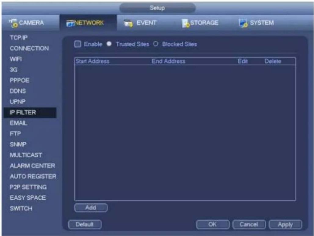
text_image
Setup CAMERA NETWORK EVENT STORAGE SYSTEM TCP/IP CONNECTION WIFI 3G PPPOE DDNS UPNP IP FILTER EMAIL FTP SNMP MULTICAST ALARM CENTER AUTO REGISTER P2P SETTING EASY SPACE SWITCH Enable ● Trusted Sites ○ Blocked Sites Start Address End Address Edit Delete Add Default OK Cancel ApplyFigure 4-130
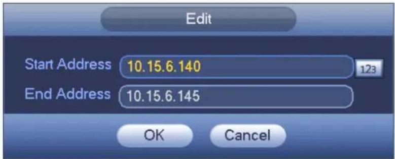
text_image
Edit Start Address 10.15.6.140 End Address 10.15.6.145 OK CancelFigure 4-131
4.14.1.10 Email
The email interface is shown as below. See Figure 4-132.
- SMTP server: Please input your email SMTP server IP here.
● Port: Please input corresponding port value here. - User name: Please input the user name to login the sender email box.
- Password: Please input the corresponding password here.
- Sender: Please input sender email box here.
- Title: Please input email subject here. System support English character and Arabic number. Max 32-digit.
- Receiver: Please input receiver email address here. System max supports 3 email boxes. System automatically filters same addresses if you input one receiver repeatedly.
- SSL enable: System supports SSL encryption box.
- Interval: The send interval ranges from 0 to 3600 seconds. 0 means there is no interval.
● Health email enable: Please check the box here to enable this function. This function allows the system to send out the test email to check the connection is OK or not.
- Interval: Please check the above box to enable this function and then set the corresponding interval. System can send out the email regularly as you set here. Click the Test button, you can see the corresponding dialogue box to see the email connection is OK or not.
Please note system will not send out the email immediately when the alarm occurs. When the alarm, motion detection or the abnormality event activates the email, system sends out the email according to the interval you specified here. This function is very useful when there are too many emails activated by the abnormality events, which may result in heavy load for the email server.
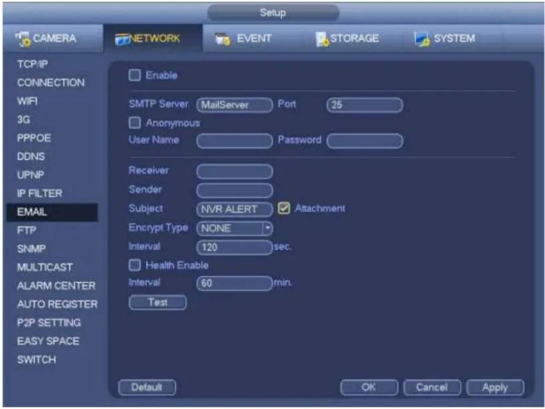
text_image
Setup CAMERA NETWORK EVENT STORAGE SYSTEM TCP/IP CONNECTION WIFI 3G PPPOE DDNS UPNP IP FILTER EMAIL FTP SNMP MULTICAST ALARM CENTER AUTO REGISTER P2P SETTING EASY SPACE SWITCH Enable SMTP Server MailServer Port 25 Anonymous User Name Password Receiver Sender Subject NVR ALERT Attachment Encrypt Type NONE Interval 120 sec. Health Enable Interval 60 min. Test Default OK Cancel ApplyFigure 4-132
4.14.1.11 FTP
You need to download or buy FTP service tool (such as Ser-U FTP SERVER) to establish FTP service. Please install Ser-U FTP SERVER first. From "start" -> "program" -> Serv-U FTP Server -> Serv-U Administrator. Now you can set user password and FTP folder. Please note you need to grant write right to FTP upload user. See Figure 4-133.
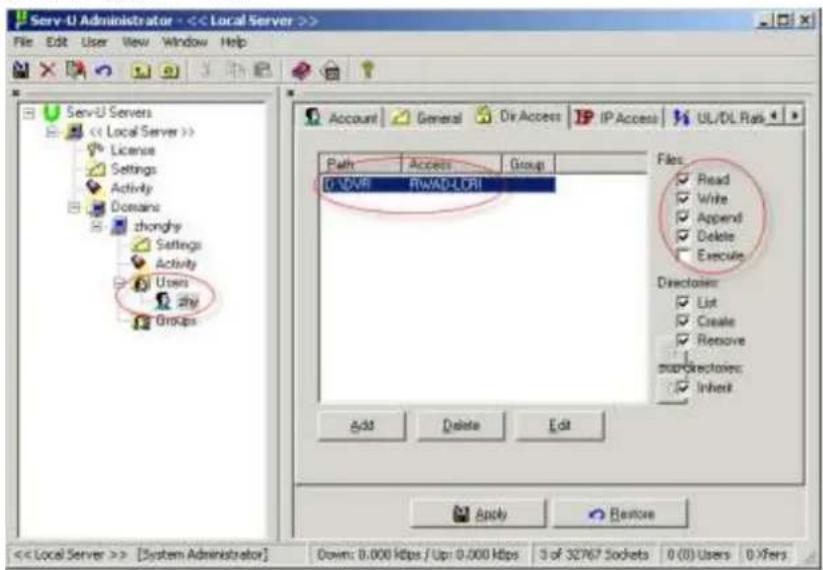
text_image
Serv-U Administrator - << Local Server >> File Edit User View Window Help Serv-U Servers << Local Server >> License Settings Activity Domains chonghy Settings Activity Users zhy Groups Account General Dir Access IP Access UL/DL Risk Path Access Group D:\LOVR RWAD-LORI Files: Read Write Append Delete Execute Directorer: List Create Remove StopDirectors: Inherit Add Delete Edit Apply Restore << Local Server >> [System Administrator] Down: 0.000 Kbps / Up: 0.000 Kbps 3 of 32767 Sockets 0 (0) Users 0 XfersFigure 4-133
You can use a PC or FTP login tool to test setup is right or not.
For example, you can login user ZHY to FTP://10.10.7.7 and then test it can modify or delete folder
or not. See Figure 4-134.
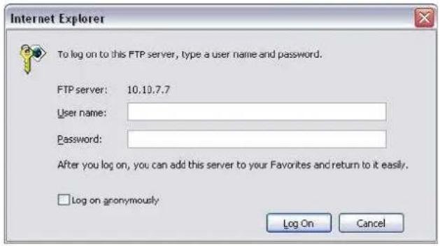
text_image
Internet Explorer To log on to this FTP server, type a user name and password. FTP server: 10.10.7.7 User name: Password: After you log on, you can add this server to your Favorites and return to it easily. Log on gronomously Log On CancelFigure 4-134
System also supports upload multiple NVRs to one FTP server. You can create multiple folders under this FTP.
FTP interface is shown as in Figure 4-135.
Please highlight the icon in front of Enable to activate FTP function.
Here you can input FTP server address, port and remote directory. When remote directory is null, system automatically create folders according to the IP, time and channel.
User name and password is the account information for you to login the FTP.
File length is upload file length. When setup is larger than the actual file length, system will upload the whole file. When setup here is smaller than the actual file length, system only uploads the set length and auto ignore the left section. When interval value is 0, system uploads all corresponding files.
After completed channel and weekday setup, you can set two periods for one each channel.
Click the Test button, you can see the corresponding dialogue box to see the FTP connection is OK or not.
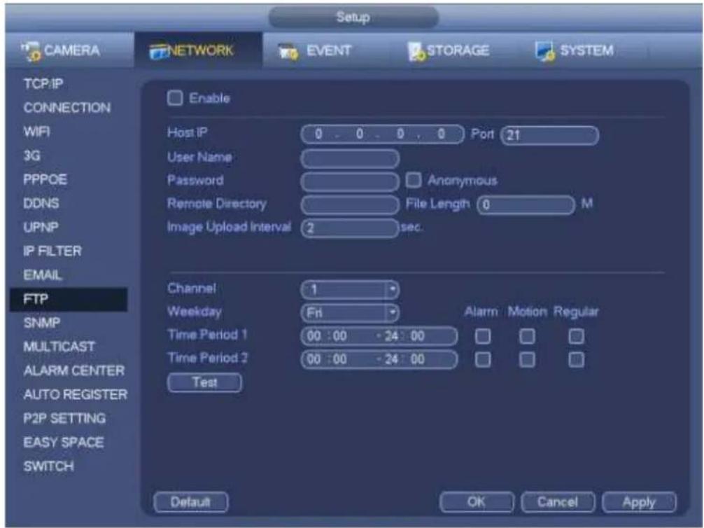
text_image
Setup CAMERA NETWORK EVENT STORAGE SYSTEM TCP/IP CONNECTION WIFI 3G PPPOE DDNS UPNP IP FILTER EMAIL FTP SNMP MULTICAST ALARM CENTER AUTO REGISTER P2P SETTING EASY SPACE SWITCH Enable Host IP 0 - 0 - 0 - 0 Port 21 User Name Password Anonymous Remote Directory File Length 0 M Image Upload Interval 2 sec. Channel 1 Weekday Fri Alarm Motion Regular Time Period 1 00:00 - 24:00 Time Period 2 00:00 - 24:00 Test Default OK Cancel ApplyFigure 4-135
4.14.1.12 SNMP
SNMP is an abbreviation of Simple Network Management Protocol. It provides the basic network management frame of the network management system. The SNMP widely used in many environments. It is used in many network device, software and system.
You can set in the following interface. See Figure 4-136.
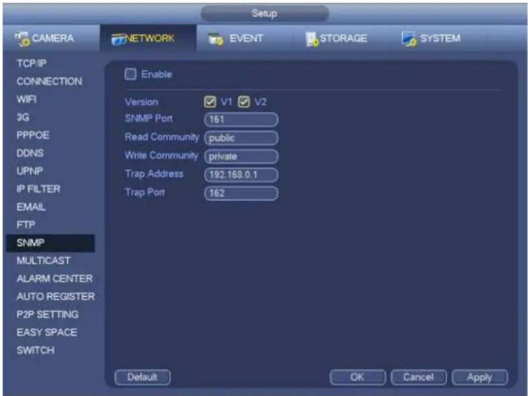
text_image
Setup CAMERA NETWORK EVENT STORAGE SYSTEM TCP/IP CONNECTION WIFI 3G PPPOE DDNS UPNP IP FILTER EMAIL FTP SNMP MULTICAST ALARM CENTER AUTO REGISTER P2P SETTING EASY SPACE SWITCH Enable Version V1 V2 SNMP Port 161 Read Community public Write Community private Trap Address 192.168.0.1 Trap Port 162 Default OK Cancel ApplyFigure 4-136
Please enable the SNMP function. Use the corresponding software tool (MIB Builder and MG-SOFT MIB Browser. You still need two MIB file: BASE-SNMP-MIB, NVR-SNMP-MIB) to connect to the device. You can get the device corresponding configuration information after successfully connection.
Please follow the steps listed below to configure.
- In Figure 4-136, check the box to enable the SNMP function. Input the IP address of the PC than is running the software in the Trap address. You can use default setup for the rest items.
- Compile the above mentioned two MIB file via the software MIB Builder.
- Run MG-SOFT MIB Browser to load the file from the previous step to the software.
- Input the device IP you want to manage in the MG-SOFT MIB Browser. Please set the corresponding version for your future reference.
- Open the tree list on the MG-SOFT MIB Browser; you can get the device configuration. Here you can see the device has how many video channels, audio channels, application version and etc.
Note
Port conflict occurs when SNMP port and Trap port are the same.
4.14.1.13 Multicast
Multicast setup interface is shown as in Figure 4-137.
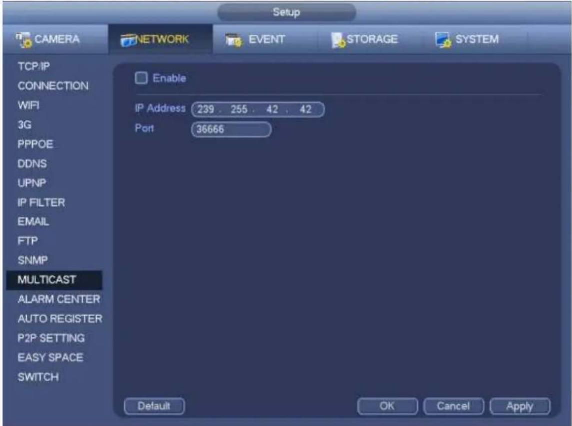
text_image
Setup CAMERA NETWORK EVENT STORAGE SYSTEM TCP/IP CONNECTION WIFI 3G PPPOE DDNS UPNP IP FILTER EMAIL FTP SNMP MULTICAST ALARM CENTER AUTO REGISTER P2P SETTING EASY SPACE SWITCH Enable IP Address 239 . 255 . 42 . 42 Port 36666 Default OK Cancel ApplyFigure 4-137
Here you can set a multiple cast group. Please refer to the following sheet for detailed information.
- IP multiple cast group address
-224.0.0.0-239.255.255.255
-“D” address space
● The higher four-bit of the first byte="1110"
● Reserved local multiple cast group address
-224.0.0.0-224.0.0.255
-TTL=1 When sending out telegraph
-For example
224.0.0.1 All systems in the sub-net
224.0.0.2 All routers in the sub-net
224.0.0.4 DVMRP router
224.0.0.5 OSPF router
224.0.0.13 PIMv2 router
● Administrative scoped addressees
-239.0.0.0-239.255.255.255
-Private address space
● Like the single broadcast address of RFC1918
- Can not be used in Internet transmission
● Used for multiple cast broadcast in limited space.
Except the above mentioned addresses of special meaning, you can use other addresses. For example:
Multiple cast IP: 235.8.8.36
Multiple cast PORT: 3666.
After you logged in the Web, the Web can automatically get multiple cast address and add it to the multiple cast groups. You can enable real-time monitor function to view the view.
Please note multiple cast function applies to special series only.
4.14.1.14 Alarm Centre
This interface is reserved for you to develop. See Figure 4-138.
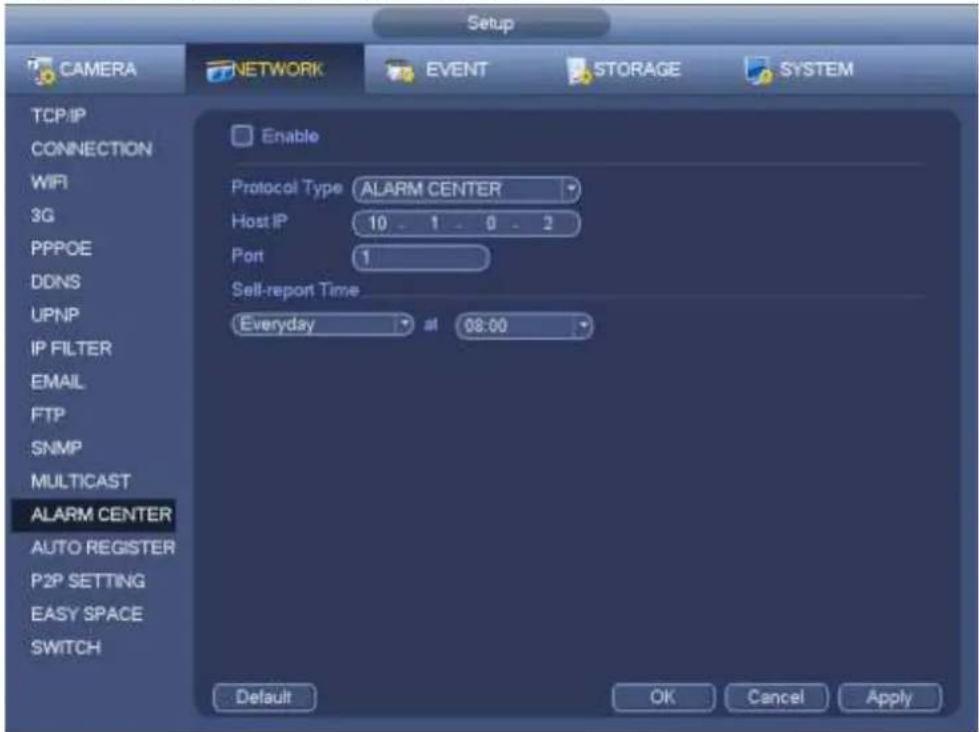
text_image
Setup CAMERA NETWORK EVENT STORAGE SYSTEM TCP/IP CONNECTION WIFI 3G PPPOE DDNS UPNP IP FILTER EMAIL FTP SNMP MULTICAST ALARM CENTER AUTO REGISTER P2P SETTING EASY SPACE SWITCH Enable Protocol Type ALARM CENTER Host IP 10 1 0 2 Port 1 Sell-report Time Everyday at 08:00 Default OK Cancel ApplyFigure 4-138
4.14.1.15 Auto register
This function allows the device to auto register to the proxy you specified. In this way, you can use the client-end to access the NVR and etc via the proxy. Here the proxy has a switch function. In the network service, device supports the server address of IPv4 or domain.
Please follow the steps listed below to use this function.
Please set proxy server address, port, and sub-device name at the device-end. Please enable the auto register function, the device can auto register to the proxy server.
1) The setup interface is shown as in Figure 4-139.
Important
Do not input network default port such as TCP port number.
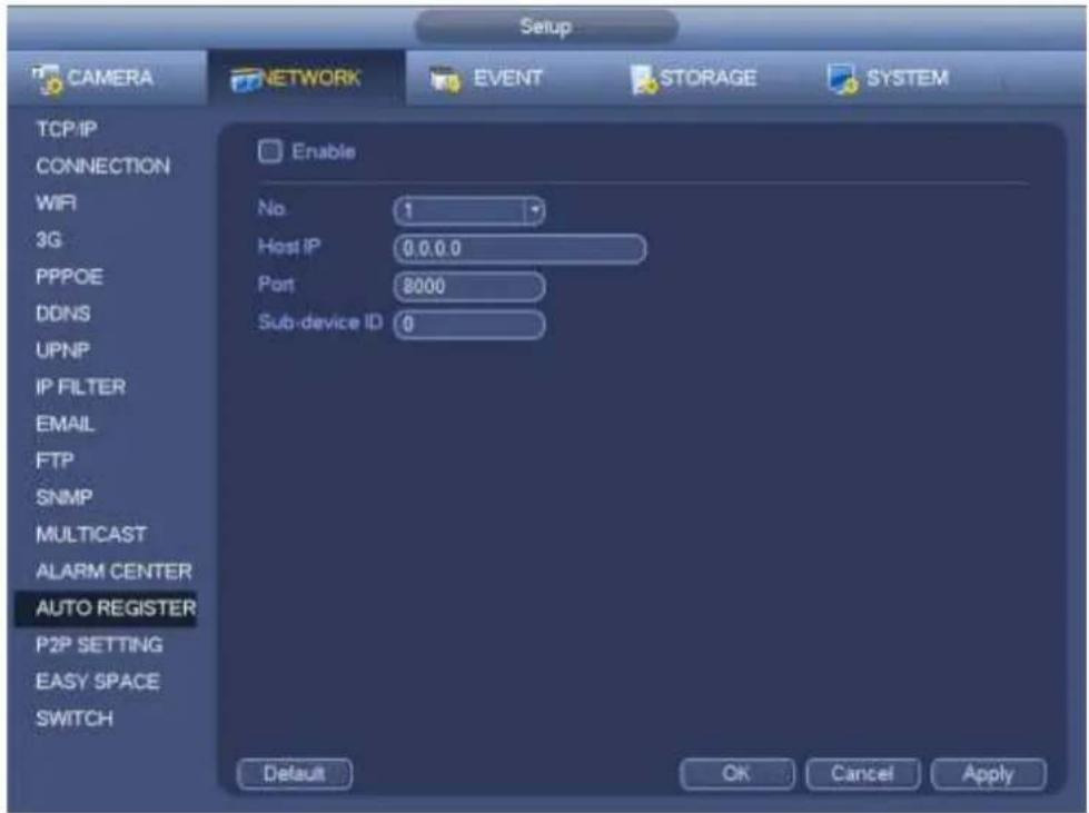
text_image
Setup CAMERA NETWORK EVENT STORAGE SYSTEM TCP/IP CONNECTION WIFI 3G PPPOE DDNS UPNP IP FILTER EMAIL FTP SNMP MULTICAST ALARM CENTER AUTO REGISTER P2P SETTING EASY SPACE SWITCH Enable No. 1 Host IP 0.0.0.0 Port 8000 Sub-device ID 0 Default OK Cancel ApplyFigure 4-139
2) The proxy server software developed from the SDK. Please open the software and input the global setup. Please make sure the auto connection port here is the same as the port you set in the previous step.
3) Now you can add device. Please do not input default port number such as the TCP port in the mapping port number. The device ID here shall be the same with the ID you input in Figure 4-139. Click Add button to complete the setup.
4) Now you can boot up the proxy server. When you see the network status is Y, it means your registration is OK. You can view the proxy server when the device is online.
Important
The server IP address can also be domain. But you need to register a domain name before you run proxy device server.
4.14.1.16 P2P
You can use your cell phone to scan the QR code and add it to the cell phone client.
Via the SN from scanning the QR code, you can access the device in the WAN. Please refer to the P2P operation manual included in the resources CD.
From main menu->Setting->Network->P2P, you can go to the following interface, the P2P interface is shown as in Figure 4-140.
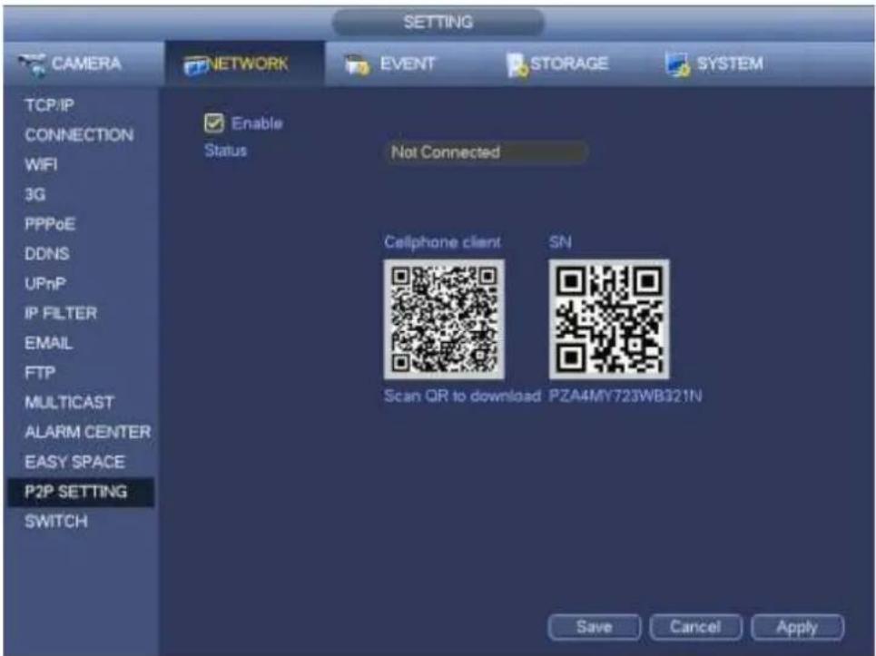
text_image
SETTING CAMERA NETWORK EVENT STORAGE SYSTEM TCP/IP CONNECTION WiFi 3G PPPoE DDNS UPnP IP FILTER EMAIL FTP MULTICAST ALARM CENTER EASY SPACE P2P SETTING SWITCH Enable Status Not Connected Cellphone client SN Scan QR to download PZA4MY723WB321N Save Cancel ApplyFigure 4-140
- Android:
Open Google Play app in your smart phone. Search gDMSS Lite or gDMSS Plus, download it and install.
- iOS:
Open App Store app in your smart phone. Search iDMSS Lite or iDMSS Plus, download it and install.
Please follow the steps listed below.

- Open App; tap
to go to the Liv preview.
- Tap at the top left corner, you can see the main menu.
- Tap Device manager button, you can use several modes (P2P/DDNS/IP and etc) to add the device.
Click to save current setup. Tap Start Live preview to view all-channel video from the connected device. See Figure 4-141.

text_image
P2P Register Mode: P2P Name: SN: Username: admin Password: •••••• Live Preview: Extra > Playback: Extra > Check VTO Start Live PreviewFigure 4-141
4.14.1.17 Easy Space
This function allows you to upload motion detect record or snapshot image to the dropbox and etc. The easy space interface is shown as below. See Figure 4-142.
Please select the easy space address from the dropdown list and then input corresponding user name and password.
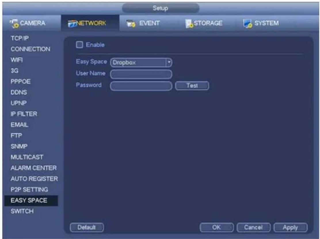
text_image
Setup CAMERA NETWORK EVENT STORAGE SYSTEM TCP/IP CONNECTION WIFI 3G PPPOE DDNS UPNP IP FILTER EMAIL FTP SNMP MULTICAST ALARM CENTER AUTO REGISTER P2P SETTING EASY SPACE SWITCH Enable Easy Space Dropbox User Name Password Test Default OK Cancel ApplyFigure 4-142
Note:
- The uploaded file is for sub stream only. Please go to record control interface (main stream->setting->Storage->Record) and then select sub stream.
- The easy space function uses upload bandwidth. Usually the recommended upload bandwidth shall be more than 512kbps and please make sure the network is stable.
- The easy space upload data adopts safe SSL encryption connection. Please enable 1-channel to upload in case this function occupies too much CPU.
4.14.1.18 SWITCH
It is for you to set IP address, subnet mask, gateway and etc of the Switch. See Figure 4-143.
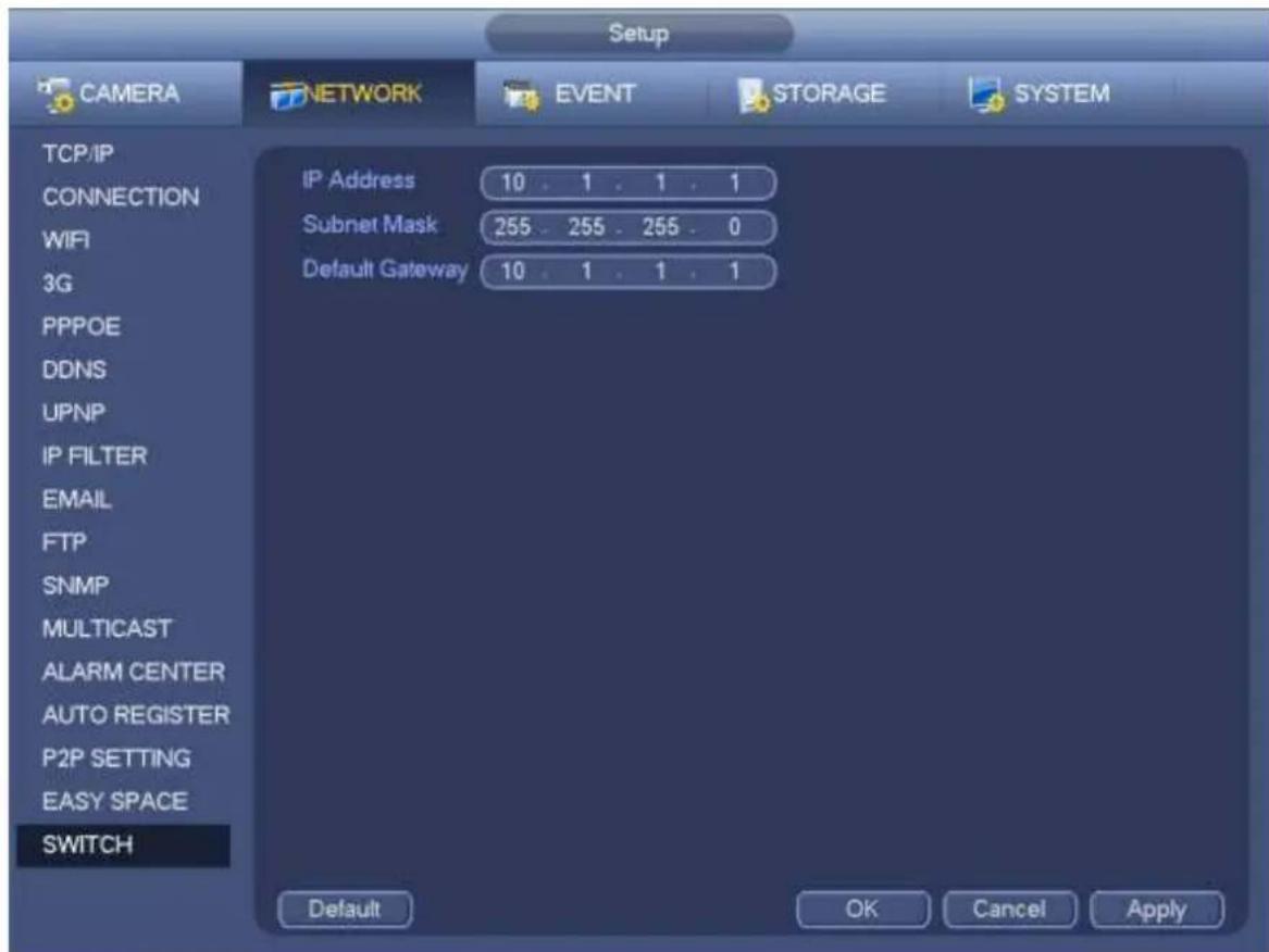
text_image
Setup CAMERA NETWORK EVENT STORAGE SYSTEM TCP/IP CONNECTION WIFI 3G PPPOE DDNS UPNP IP FILTER EMAIL FTP SNMP MULTICAST ALARM CENTER AUTO REGISTER P2P SETTING EASY SPACE SWITCH IP Address 10 . 1 . 1 . 1 Subnet Mask 255 . 255 . 255 . 0 Default Gateway 10 . 1 . 1 . 1 Default OK Cancel ApplyFigure 4-143
4.14.2 Network Test
In this interface, you can see network test and network load information.
4.14.2.1 Network Test
From main menu->Info-Network->Test, the network test interface is shown as in Figure 4-144.
- Destination IP: Please input valid IPV4 address and domain name.
- Test: Click it to test the connection with the destination IP address. The test results can display average delay and packet loss rate and you can also view the network status as OK, bad, no connection and etc.
- Network Sniffer backup: Please insert USB2.0 device and click the Refresh button, you can view the device on the following column. You can use the dropdown list to select peripheral device. Click Browse button to select the snap path. The steps here are same as preview backup operation.
You can view all connected network adapter names (including Ethernet, PPPoE, WIFI, and 3G), you can click the button on the right panel to begin Sniffer. Click the grey stop button to stop. Please note system can not Sniffer several network adapters at the same time.
After Sniffer began, you can exit to implement corresponding network operation such as login WEB, monitor. Please go back to Sniffer interface to click □stop Sniffer. System can save the packets to the specified path. The file is named after “Network adapter name+time”. You can use software such as Wireshark to open the packets on the PC for the professional engineer to solve complicated problems.

text_image
INFO SYSTEM EVENT NETWORK LOG ONLINE USERS LOAD TEST TEST Destination IP Test Test Result Network Sniffer Packet Backup Device Name sdc1(USB DISK) Refresh Address Browse Name IP Sniffer Packet Size Sniffer Packet Backup LAN1 10.15.6.143 0KBFigure 4-144
4.14.2.2 Network Load
From main menu->Info-Network->Load, network load is shown as in Figure 4-145. Here you can view the follow statistics of the device network adapter.
Here you can view information of all connected network adapters. The connection status is shown as offline if connection is disconnected. Click one network adapter, you can view the flow statistics such as send rate and receive rate at the top panel
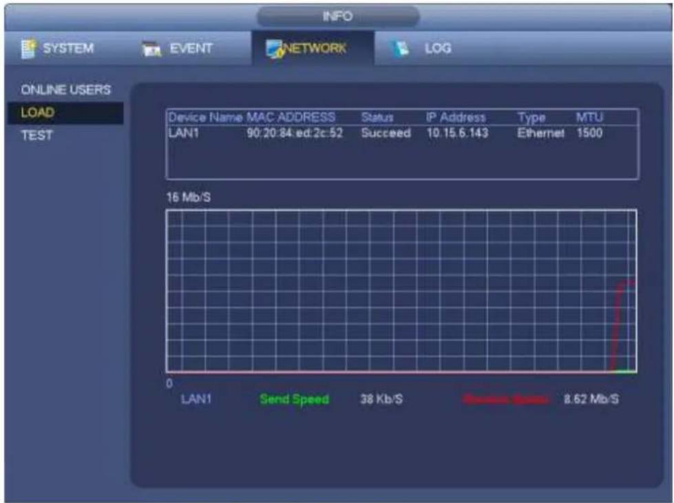
text_image
INFO SYSTEM EVENT NETWORK(LOG ONLINE USERS LOAD TEST Device Name MAC ADDRESS Status IP Address Type MTU LAN1 90:20:84 ed:2c:52 Succeed 10.15.6.143 Ethernet 1500 16 Mb/S 0 LAN1 Send Speed 38 Kb/S 8.62 Mb/SFigure 4-145
4.15 HDD Setup
Here you can view HDD information such as type, status, total capacity, record time and etc. The operation includes format, resume from error, change HDD property (Read write, Read-only). Here you can also set alarm and HDD storage position.
4.15.1 Format
a) From Mani-menu->Setting->Storage->HDD Manager, you can go to HDD management interface. See Figure 4-146.
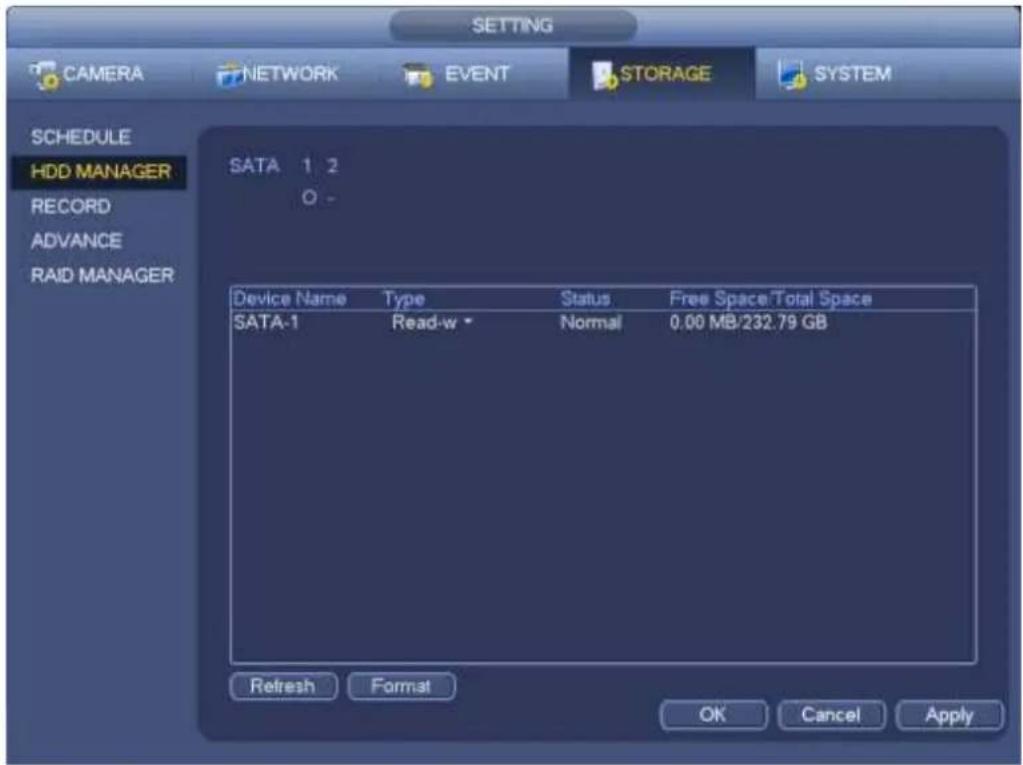
text_image
SETTING CAMERA NETWORK EVENT STORAGE SYSTEM SCHEDULE HDD MANAGER RECORD ADVANCE RAID MANAGER SATA 1 2 O - Device Name Type Status Free Space/Total Space SATA-1 Read-w Normal 0.00 MB/232.79 GB Refresh Format OK Cancel ApplyFigure 4-146
b) Select a HDD and then select format from the dropdown list. Click Execute button.
c) Click OK button to complete the setup. You can see system needs to restart to activate current setup.
4.15.2 HDD Information
Here is to list hard disk type, total space, free space, and status. See Figure 4-147.
- means current HDD is normal.. - means there is no HDD.
If disk is damaged, system shows as “?”. Please remove the broken hard disk before you add a new one.
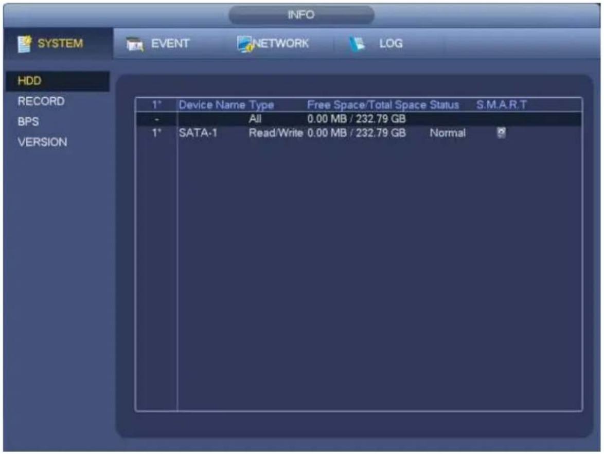
text_image
INFO SYSTEM EVENT NETWORK LOG HDD RECORD BPS VERSION 1* Device Name Type Free Space/Total Space Status S.M.A.R.T - All 0.00 MB / 232.79 GB 1* SATA-1 Read/Write 0.00 MB / 232.79 GB NormalFigure 4-147
In Figure 4-147, click one HDD item, the S.M.A.R.T interface is shown as in Figure 4-148.
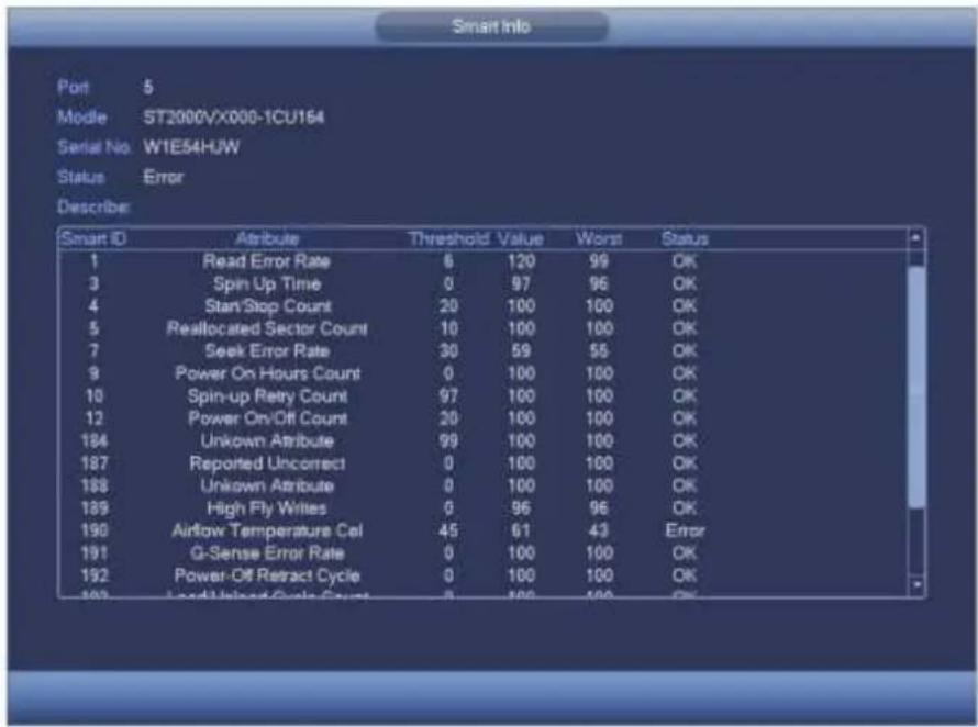
text_image
Smart Info Port 5 Mode ST2000VX000-1CU164 Serial No W1E54HJW Status Error Describe: Smart ID Attribute Threshold Value Worst Status 1 Read Error Rate 6 120 99 OK 3 Spin Up Time 0 97 96 OK 4 StartStop Count 20 100 100 OK 5 Reallocated Sector Count 10 100 100 OK 7 Seek Error Rate 30 59 55 OK 9 Power On Hours Count 0 100 100 OK 10 Spin-up Retry Count 97 100 100 OK 12 Power On/Off Count 20 100 100 OK 184 Unknown Attribute 99 100 100 OK 187 Reported Uncorrect 0 100 100 OK 188 Unknown Attribute 0 100 100 OK 189 High Fly Writes 0 96 96 OK 190 Airflow Temperature Coi 45 61 43 Error 191 Q-Sense Error Rate 0 100 100 OK 192 Power-Off Retract Cycle 0 100 100 OK 193 Load Unlaced Cycle Count 8 100 100 OKFigure 4-148
| Parameter | Function |
| SATA | 1 here means there is 1 HDD.For different series product, the max HDD amount may vary,When HDD is working properly, system is shown as O. . “_” means there is no HDD. |
| SN | You can view the HDD amount the device connected to; * means the second HDD is current working HDD. |
| Type | The corresponding HDD property. |
| Total space | The HDD total capacity. |
| Free space | The HDD free capacity. |
| Status | HDD can work properly or not. |
| Bad track | Display there is bad track or not. |
| Page up | Click it to view previous page. |
| Page down | Click it to view the next page. |
| View recording time | Click it to view HDD record information (file start time and end time). |
| View HDD type and capability | Click it to view HDD property, status and etc, |
4.15.3 Advanced
It is to set HDD group, and HDD group setup for main stream, sub stream and snapshot operation
Important
HDD group and quota mode can not be valid at the same time. System needs to restart once you change the mode here.
The HDD group mode is shown as in Figure 4-149.
- HDD: Here you can view the HDD amount the device can support.
● Group: It lists the HDD Group number of current hard disk.
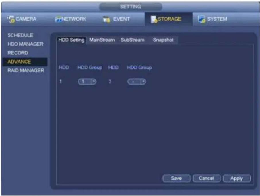
text_image
SETTING CAMERA NETWORK EVENT STORAGE SYSTEM SCHEDULE HDD MANAGER RECORD ADVANCE RAID MANAGER HDD Setting MainStream SubStream Snapshot HDD HDD Group HDD HDD Group 1 1 2 - Save Cancel ApplyFigure 4-149
Please select the correspond group from the dropdown list and then click Apply button.
Click main stream/sub stream/snapshot button to set corresponding HDD group information. See Figure 4-150 through Figure 4-152.
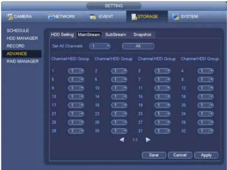
text_image
SETTING CAMERA NETWORK EVENT STORAGE SYSTEM SCHEDULE HDD MANAGER RECORD ADVANCE RAID MANAGER HDD Setting MainStream SubStream Snapshot Set All Channels 1 All Channel HDD Group Channel HDD Group Channel HDD Group Channel HDD Group 1 1 2 1 3 1 4 1 5 1 6 1 7 1 8 1 9 1 10 1 11 1 12 1 12 1 14 1 15 1 16 1 17 1 18 1 19 1 20 1 21 1 22 1 23 1 24 1 25 1 26 1 27 1 28 1 29 1 30 1 31 1 32 1 1/1 Save Cancel ApplyFigure 4-150
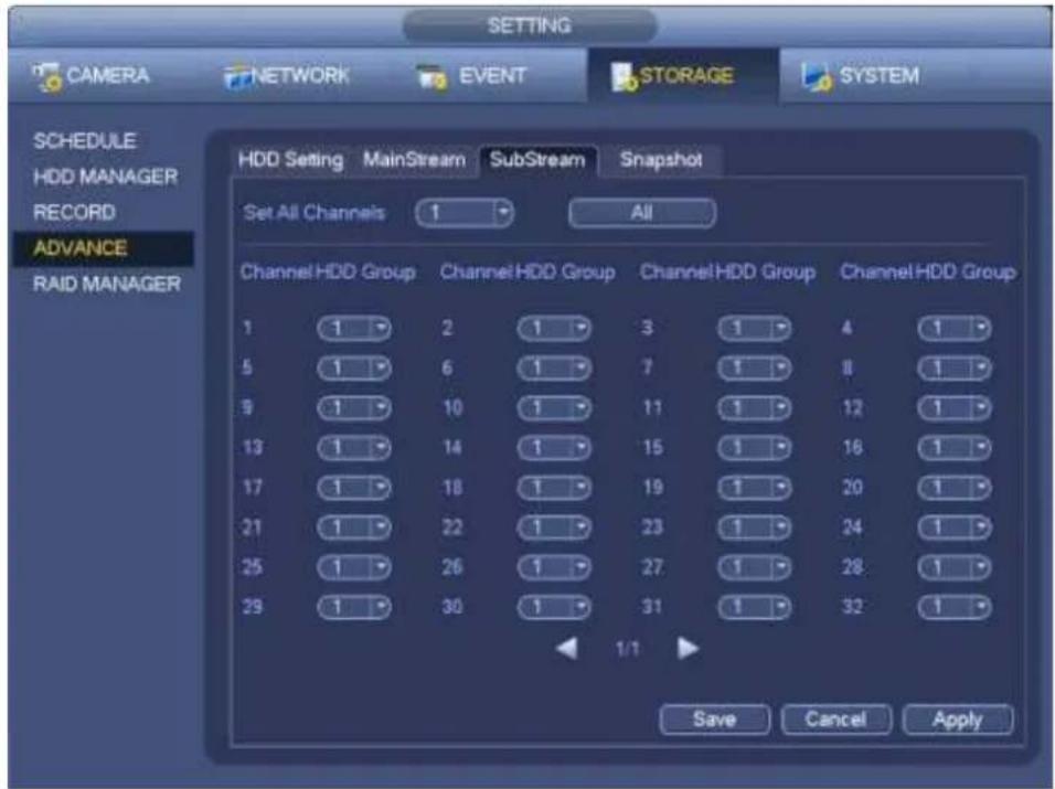
text_image
SETTING CAMERA NETWORK EVENT STORAGE SYSTEM SCHEDULE HDD MANAGER RECORD ADVANCE RAID MANAGER HDD Setting MainStream SubStream Snapshot Set All Channels 1 All Channel HDD Group Channel HDD Group Channel HDD Group Channel HDD Group 1 1 2 1 3 1 4 1 5 1 6 1 7 1 8 1 9 1 10 1 11 1 12 1 13 1 14 1 15 1 16 1 17 1 18 1 19 1 20 1 21 1 22 1 23 1 24 1 25 1 26 1 27 1 28 1 29 1 30 1 31 1 32 1 1/1 Save Cancel ApplyFigure 4-151
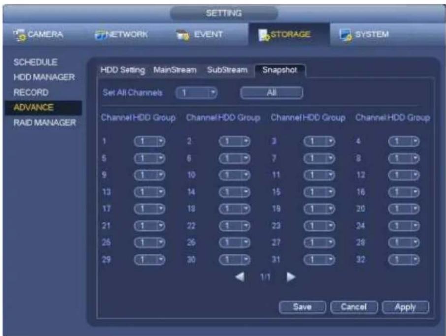
text_image
SETTING CAMERA NETWORK EVENT STORAGE SYSTEM SCHEDULE HDD MANAGER RECORD ADVANCE RAID MANAGER HDD Setting MainStream SubStream Snapshot Set All Channels 1 All Channel HDD Group Channel HDD Group Channel HDD Group Channel HDD Group 1 1 2 1 3 1 4 1 5 1 6 1 7 1 8 1 9 1 10 1 11 1 12 1 13 1 14 1 15 1 16 1 17 1 18 1 19 1 20 1 21 1 22 1 23 1 24 1 26 1 26 1 27 1 28 1 29 1 30 1 31 1 32 1 1/1 Save Cancel ApplyFigure 4-152
4.15.4 HDD Detect
Note
This function is for some series product only.
The HDD detect function is to detect HDD current status so that you can clearly understand the HDD performance and replace the malfunction HDD.
There are two detect types:
- Quick detect is to detect via the universal system files. System can quickly complete the HDD scan. If you want to use this function, please make sure the HDD is in use now. If the HDD is removed from other device, please make sure the write-data once was full after it installed on current device.
- Global detect adopts Windows mode to scan. It may take a long time and may affect the HDD that is recording.
4.15.4.1 Manual Detect
From main menu->Setting->Storage->HDD Detect->Manual Detect, the interface is shown as below. See Figure 4-153.
Please select detect type and HDD. Click start detect to begin. You can view the corresponding detect information.
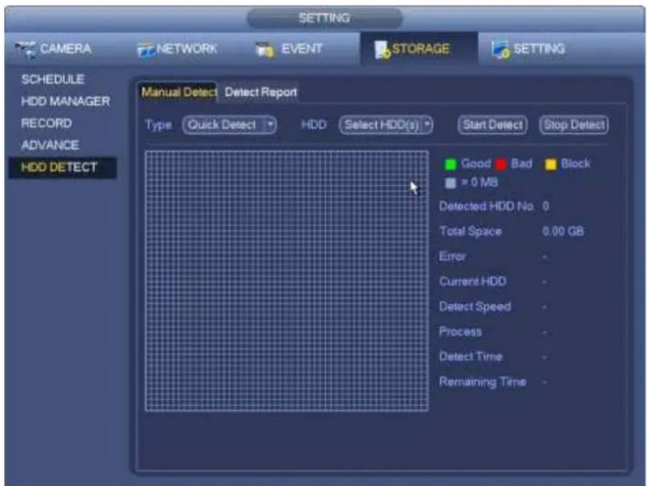
text_image
SETTING CAMERA NETWORK EVENT STORAGE SETTING SCHEDULE HDD MANAGER RECORD ADVANCE HDD DETECT Manual Detect Detect Report Type Quick Detect HDD Select HDD(s) Start Detect Stop Detect Good Bad Block = 0 MB Detected HDD No. 0 Total Space 0.00 GB Error - Current HDD - Detect Speed - Process - Detect Time - Remaining Time -Figure 4-153
4.15.4.2 Detect Report
After the detect operation, you can go to the detect report to view corresponding information.
From main menu->Setting->Storage->HDD Detect->Manual Detect, the interface is shown as below. See Figure 4-154.
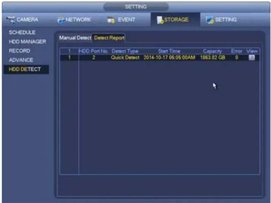
text_image
SETTING CAMERA NETWORK EVENT STORAGE SETTING SCHEDULE HDD MANAGER RECORD ADVANCE HDD DETECT Manual Detect Detect Report 1 HDD Port No. Detect Type Start Time Capacity Error View 1 2 Quick Detect 2014-10-17 06:05:00AM 1863.02 GB 0Figure 4-154
Click View, you can see the detailed information such as detect result, backup and S.M.A.R.T. See Figure 4-155 and Figure 4-156.
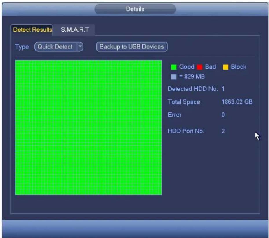
text_image
Details Detect Results S.M.A.R.T Type Quick Detect Backup to USB Devices Good Bad Block = 829 MB Detected HDD No. 1 Total Space 1863.02 GB Error 0 HDD Port No. 2Figure 4-155
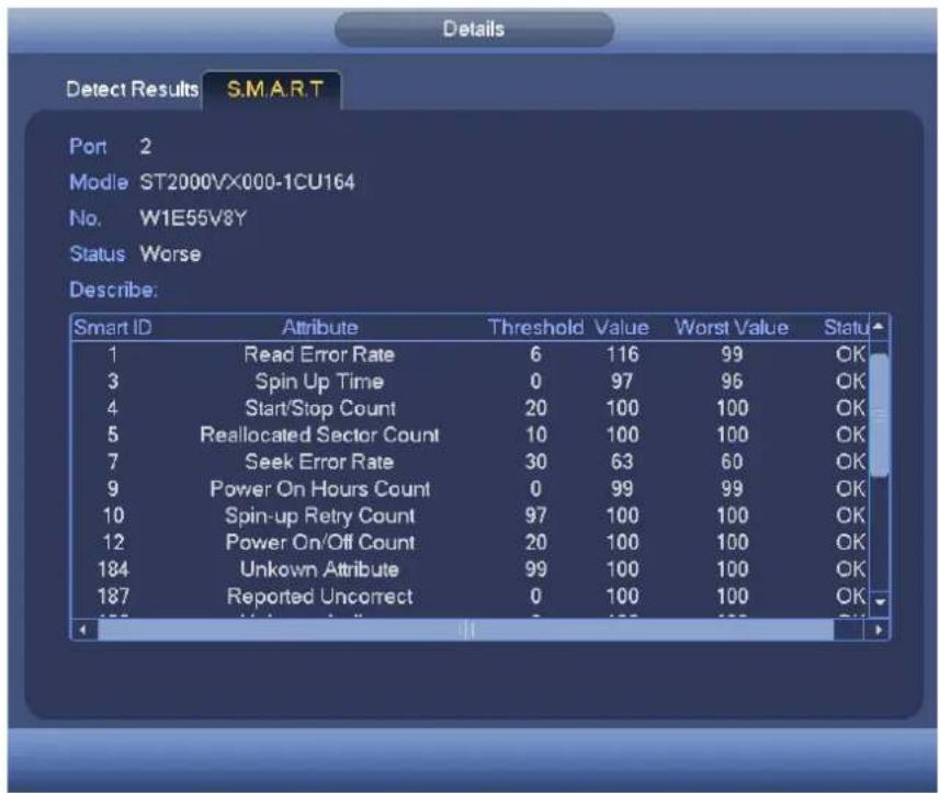
text_image
Details Detect Results S.M.A.R.T Port 2 Mode ST2000VX000-1CU164 No. W1E55V8Y Status Worse Describe: Smart ID Attribute Threshold Value Worst Value Status 1 Read Error Rate 6 116 99 OK 3 Spin Up Time 0 97 96 OK 4 Start/Stop Count 20 100 100 OK 5 Reallocated Sector Count 10 100 100 OK 7 Seek Error Rate 30 63 60 OK 9 Power On Hours Count 0 99 99 OK 10 Spin-up Retry Count 97 100 100 OK 12 Power On/Off Count 20 100 100 OK 184 Unknown Attribute 99 100 100 OK 187 Reported Uncorrect 0 100 100 OKFigure 4-156
4.15.5 RAID Manager
Important
Please make sure your purchased product support the RAID function, otherwise you can not see the following interface.
Right now, RAID supports Raid0, Raid1, Raid5, Raid6, and Raid10. Local hotspare supports Raid1, Raid5, Raid6, and Raid10.
4.15.5.1 RAID Config
It is for you to manage RAID HDD. It can display RAID name, type, free space, total space, status and etc. Here you can add/delete RAID HDD.
Click Add button to select RAID type and then select HDDs, click OK button to add. See Figure 4-157.
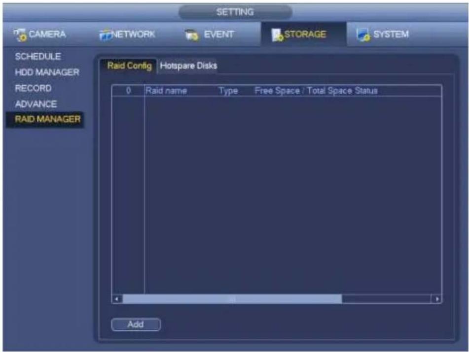
text_image
SETTING CAMERA NETWORK EVENT STORAGE SYSTEM SCHEDULE HDD MANAGER RECORD ADVANCE RAID MANAGER Raid Config Hotspare Disks 0 Raid name Type Free Space / Total Space Status AddFigure 4-157
4.15.5.2 Hotspare disks
Click Hotspare disks tab name, you can add the hot spare HDD. See Figure 4-158. The type includes two options:
- Global: It is global hotspare disk. When any RAID becomes degrading, it can replace and build the RAID.
- Local: It is local hotspare disk. When the specified RAID becomes degrading, it can replace and build the RAID.
Select a hot spare device and then click Delete button. Click Apply button to delete.
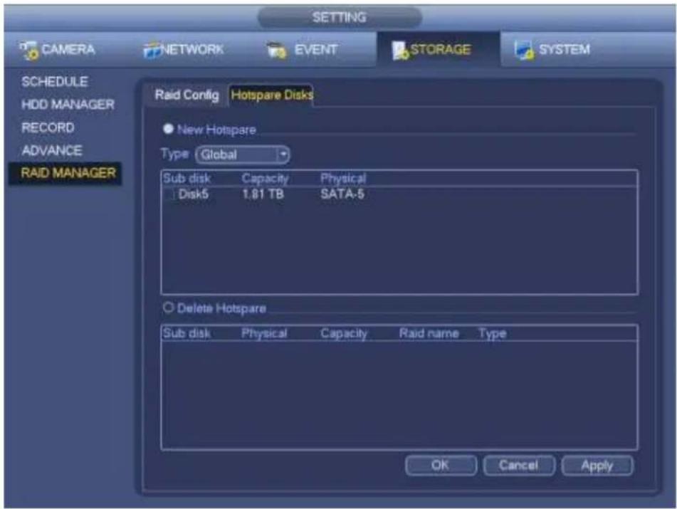
text_image
SETTING CAMERA NETWORK EVENT STORAGE SYSTEM SCHEDULE HDD MANAGER RECORD ADVANCE RAID MANAGER Raid Config Hotspare Disks New Hotspare Type Global Sub disk Capacity Physical Disk5 1.81 TB SATA-5 Delete Hotspare Sub disk Physical Capacity Raid name Type OK Cancel ApplyFigure 4-158
4.16 Basic Setups
Set NVR basic setup, device setup and other setups.
4.16.1 Device Setup
From Main menu->Setting->System->General, you can go to the general interface. See Figure 4-160.
- Pack duration: Here is for you to specify record duration. The value ranges from 0 to 120 minutes. Default value is 60 minutes.
● Device ID: Please input a corresponding device name here.
● Device No: When you are using one remote control (not included in the accessory bag) to control several NVRs, you can give a name to each NVR for your management.
- Language: System supports various languages: Chinese (simplified), Chinese (Traditional), English, Italian, Japanese, French, Spanish (All languages listed here are optional. Slight difference maybe found in various series.)
● Video standard: There are two formats: NTSC and PAL.
- HDD full: Here is for you to select working mode when hard disk is full. There are two options: stop recording or rewrite. If current working HDD is overwritten or the current HDD is full while the next HDD is no empty, then system stops recording, If the current HDD is full and then next HDD is not empty, then system overwrites the previous files.
- Pack duration: Here is for you to specify record duration. The value ranges from 1 to 120 minutes. Default value is 60 minutes.
● Realtime play: It is to set playback time you can view in the preview interface. The value ranges from 5 to 60 minutes.
- Auto logout: Here is for you to set auto logout interval once login user remains inactive for a specified time. Value ranges from 0 to 60 minutes.
- Navigation bar: Check the box here, system displays the navigation bar on the interface.
- IPC Time Sync: You can input an interval here to synchronize the NVR time and IPC time.
- Startup wizard: Once you check the box here, system will go to the startup wizard directly when the system restarts the next time. Otherwise, it will go to the login interface.
- Mouse sensitivity: You can set double click speed via dragging the slide bard. You can Click Default button to restore default setup.
- Enable IVS: Check the box to enable IVS function, system can display IVS rule on the preview interface.
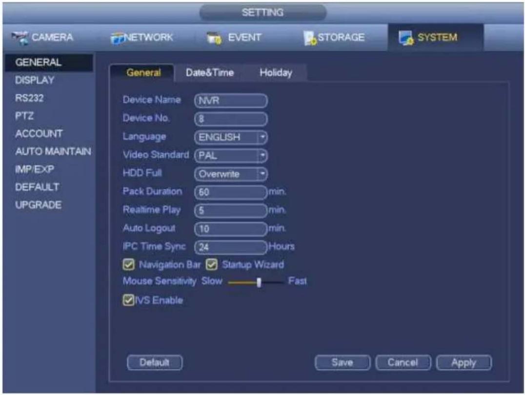
text_image
SETTING CAMERA NETWORK EVENT STORAGE SYSTEM GENERAL DISPLAY RS232 PTZ ACCOUNT AUTO MAINTAIN IMP/EXP DEFAULT UPGRADE General Date&Time Holiday Device Name NVR Device No. 8 Language ENGLISH Video Standard PAL HDD Full Overwrite Pack Duration 60 min. Realtime Play 5 min. Auto Logout 10 min. IPC Time Sync 24 Hours Navigation Bar Startup Wizard Mouse Sensitivity Slow Fast IVS Enable Default Save Cancel ApplyFigure 4-159
4.16.2 Data and Time
From Main menu->Setting->System->General, you can go to the general interface. See Figure 4-160.
● System time: Here is for you to set system time
- Date format: There are three types: YYYY-MM-DD: MM-DD-YYYY or DD-MM-YYYY.
- Date separator: There are three denotations to separate date: dot, beeline and solidus.
- DST: Here you can set DST time and date by week or by date. Please enable DST function and then select setup mode. Please input start time and end time and click Save button.
● Time format: There are two types: 24-hour mode or 12-hour mode.
● NTP: It is to set NTP server, port and interval.
Note:
Since system time is very important, do not modify time casually unless there is a must!
Before your time modification, please stop record operation first!
After completing all the setups please click save button, system goes back to the previous menu.
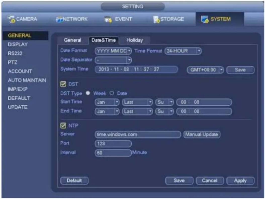
text_image
SETTING CAMERA NETWORK EVENT STORAGE SYSTEM GENERAL DISPLAY RS232 PTZ ACCOUNT AUTO MAINTAIN IMP/EXP DEFAULT UPDATE General Date&Time Holiday Date Format YYYY MM DC Time Format 24-HOUR Date Separator - System Time 2013 - 11 - 08 11 : 37 : 37 GMT+08:00 Save DST DST Type Week Date Start Time Jan Last Su 00 : 00 End Time Jan Last Su 00 : 00 NTP Server time.windows.com Manual Update Port 123 Interval 60 Minute Default Save Cancel ApplyFigure 4-160
4.16.3 Holiday
Please refer to chapter 4.10.6 for detailed information.
4.17 Device Maintenance and Manager
4.17.1 System Info
4.17.1.1 Version
From main menu->Info->System->version, you can go to version interface.
Here is for you to view some version information. See Figure 4-161. Please note the following figure for reference only.
- Channel
- Alarm in
- Alarm out
- System version
- Build Date
- Web
- Serial number
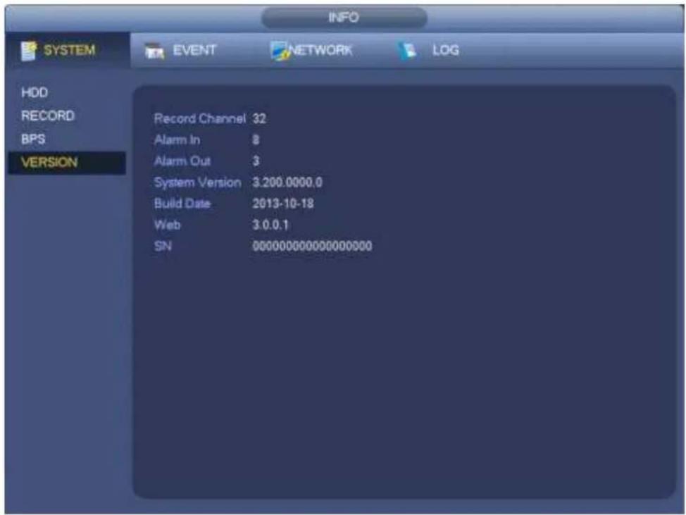
text_image
INFO SYSTEM EVENT NETWORK(LOG HDD RECORD BPS VERSION Record Channel 32 Alarm In 8 Alarm Out 3 System Version 3.200.0000.0 Build Date 2013-10-18 Web 3.0.0.1 SN 000000000000000000Figure 4-161
4.17.1.2 BPS
Here is for you to view current video bit rate (kb/s) and resolution. See Figure 4-162.
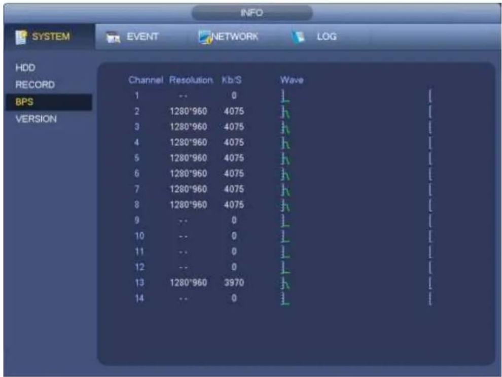
text_image
INFO SYSTEM EVENT NETWORK LOG HDD RECORD BPS VERSION Channel Resolution Kb/S Wave 1 -- 0 L 2 1280*960 4075 H 3 1280*960 4075 H 4 1280*960 4075 H 5 1280*960 4075 H 6 1280*960 4075 H 7 1280*960 4075 H 8 1280*960 4075 H 9 -- 0 L 10 -- 0 L 11 -- 0 L 12 -- 0 L 13 1280*960 3970 H 14 -- 0 LFigure 4-162
4.17.1.3 Online User
Here is for you manage online users connected to your NVR. See Figure 4-163.
You can click button to disconnect or block one user if you have proper system right.
System detects there is any newly added or deleted user in each five seconds and refresh the list automatically.
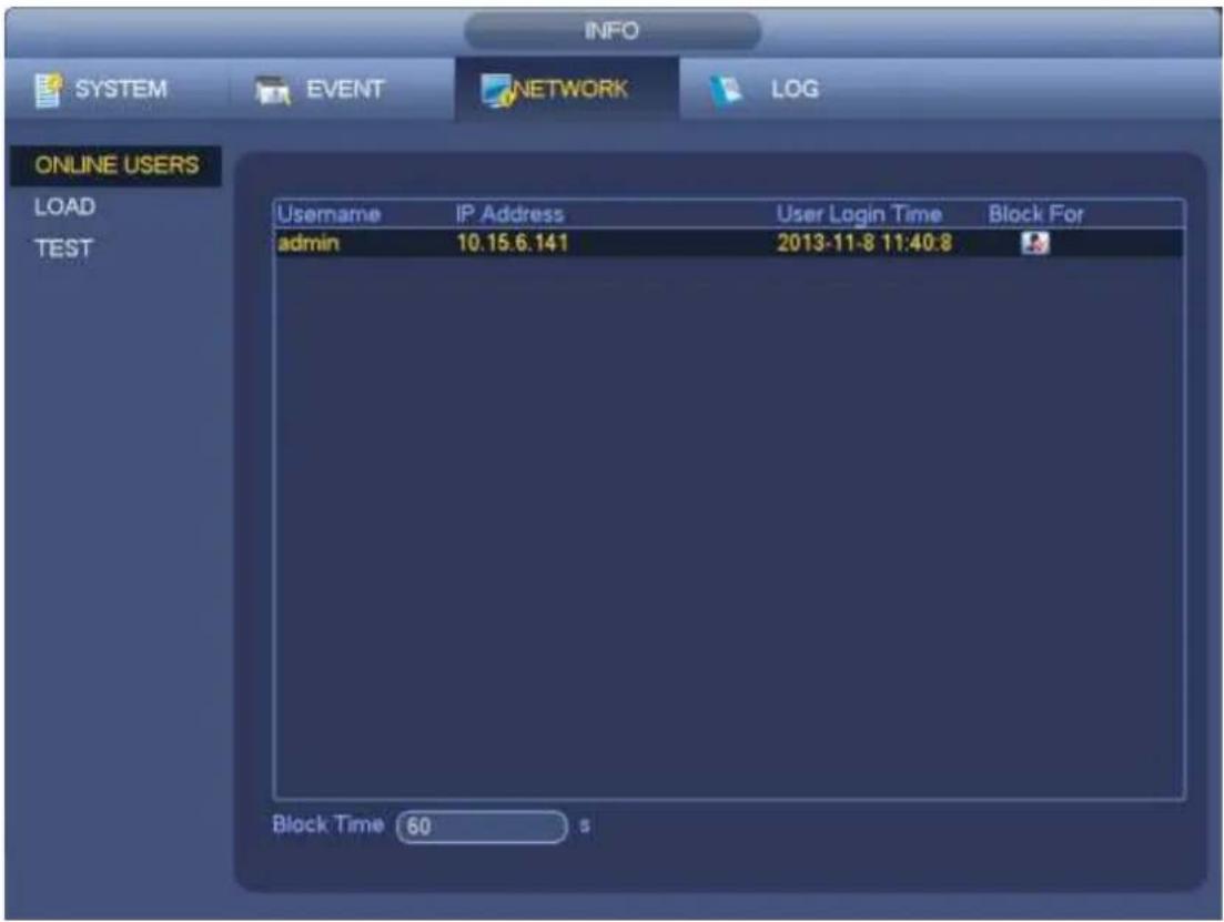
text_image
INFO SYSTEM EVENT NETWORK(LOG ONLINE USERS LOAD TEST Username IP Address User Login Time Block For admin 10.15.6.141 2013-11-8 11:40:8 Block Time 60 sFigure 4-163
4.17.1.4 Remote Device Information
From main menu->info-Event, here you can view the channel status of the remote device, connection log and etc. See Figure 4-164.
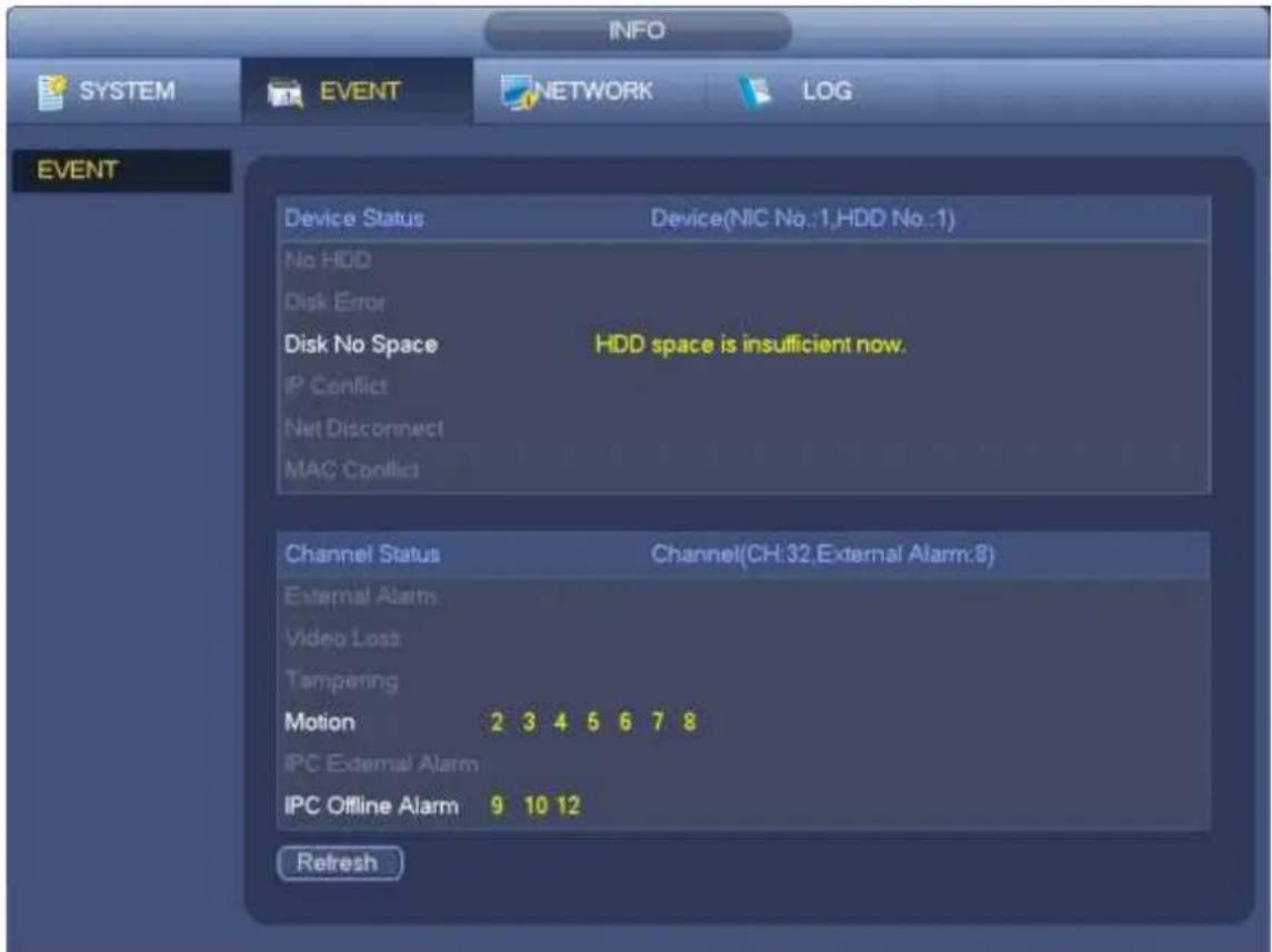
text_image
INFO SYSTEM EVENT NETWORK(LOG EVENT Device Status Device(NIC No.:1,HDD No.:1) No HDD Disk Error Disk No Space HDD space is insufficient now. IP Conflict Net Disconnect MAC Conflict Channel Status Channel(CH:32.External Alarm:8) External Alarm Video Loss Tampering Motion 2 3 4 5 6 7 8 IPC External Alarm IPC Offline Alarm 9 10 12 RefreshFigure 4-164
4.17.1.5 Remote
4.17.1.5.1 Device Status
Here you can view the IPC status of the corresponding channel such as motion detect, video loss, tampering, alarm and etc. See Figure 4-165.
- IPC status: : Front-end does not support. : Front-end supports. : There is alarm
event from current front-end.
- Connection status: : Connection succeeded. : Connection failed.
- Refresh: Click it to get latest front-end channel status.
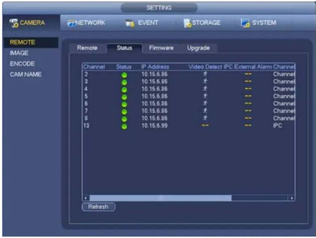
text_image
CAMERA NETWORK EVENT STORAGE SYSTEM REMOTE IMAGE ENCODE CAM NAME Remote Status Firmware Upgrade Channel Status IP Address Video Detect IPC External Alarm Channel 2 ● 10.15.6.86 ★ -- Channel 3 ● 10.15.6.86 ★ -- Channel 4 ● 10.15.6.86 ★ -- Channel 5 ● 10.15.6.86 ★ -- Channel 6 ● 10.15.6.86 ★ -- Channel 7 ● 10.15.6.86 ★ -- Channel 8 ● 10.15.6.86 ★ -- Channel 13 ● 10.15.6.99 -- -- IPC RefreshFigure 4-165
4.17.1.5.2 Firmware
It is to view channel, IP address, manufacturer, type, system version, SN, video input, audio input, external alarm and etc. See Figure 4-166.
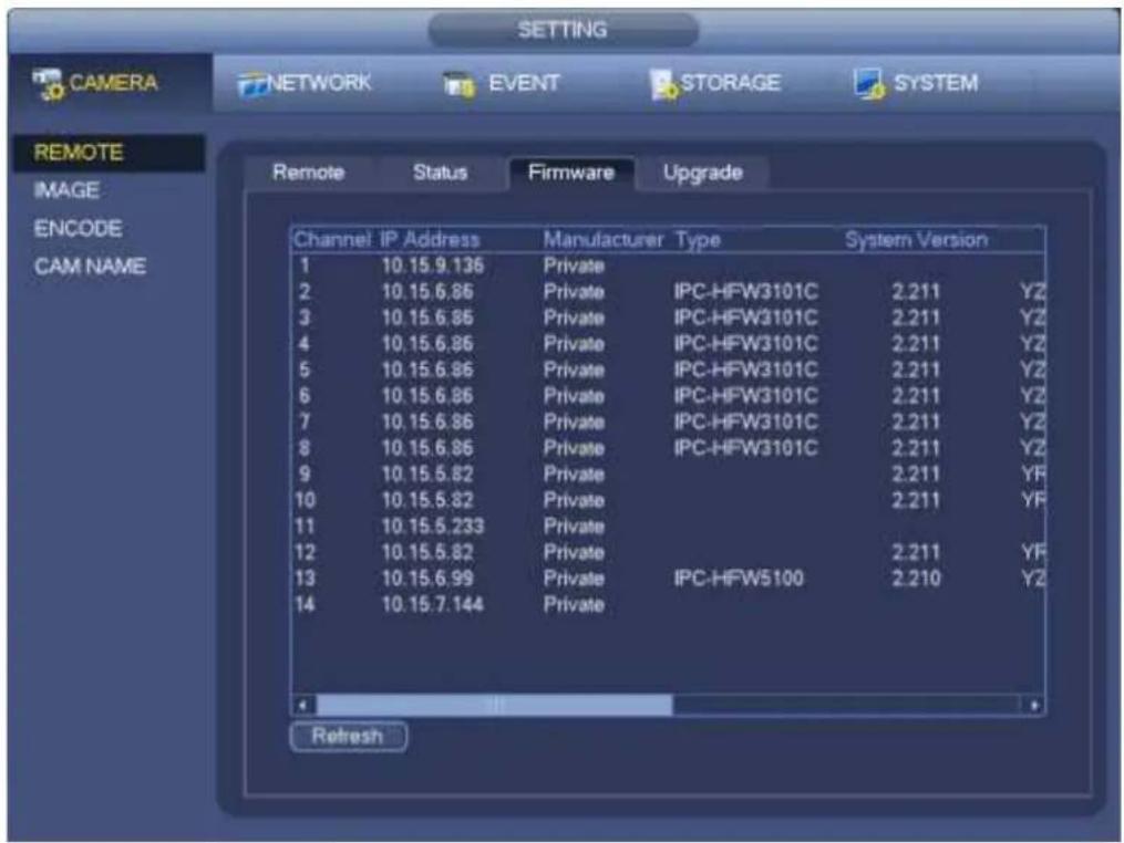
text_image
SETTING CAMERA NETWORK EVENT STORAGE SYSTEM REMOTE IMAGE ENCODE CAM NAME Remote Status Firmware Upgrade Channel IP Address Manufacturer Type System Version 1 10.15.9.136 Private 2 10.15.6.86 Private IPC-HFW3101C 2.211 YZ 3 10.15.6.86 Private IPC-HFW3101C 2.211 YZ 4 10.15.6.86 Private IPC-HFW3101C 2.211 YZ 5 10.15.6.86 Private IPC-HFW3101C 2.211 YZ 6 10.15.6.86 Private IPC-HFW3101C 2.211 YZ 7 10.15.6.86 Private IPC-HFW3101C 2.211 YZ 8 10.15.6.86 Private IPC-HFW3101C 2.211 YZ 9 10.15.5.82 Private 2.211 YF 10 10.15.5.82 Private 2.211 YF 11 10.15.5.233 Private 12 10.15.5.82 Private 2.211 YF 13 10.15.6.99 Private IPC-HFW5100 2.210 YZ 14 10.15.7.144 Private RefreshFigure 4-166
4.17.2 Log
From Main menu->Info->Log, you can go to the following interface. See Figure 4-167.
- Start time/end time: Pleased select start time and end time, then click search button. You can view the log files in a list. System max displays 100 logs in one page. It can max save 1024 log files. Please use page up/down button on the interface or the front panel to view more.
Tips
Double click a log item to view its detailed information. See Figure 4-168.
Click PgUp/PgDn to view more logs.
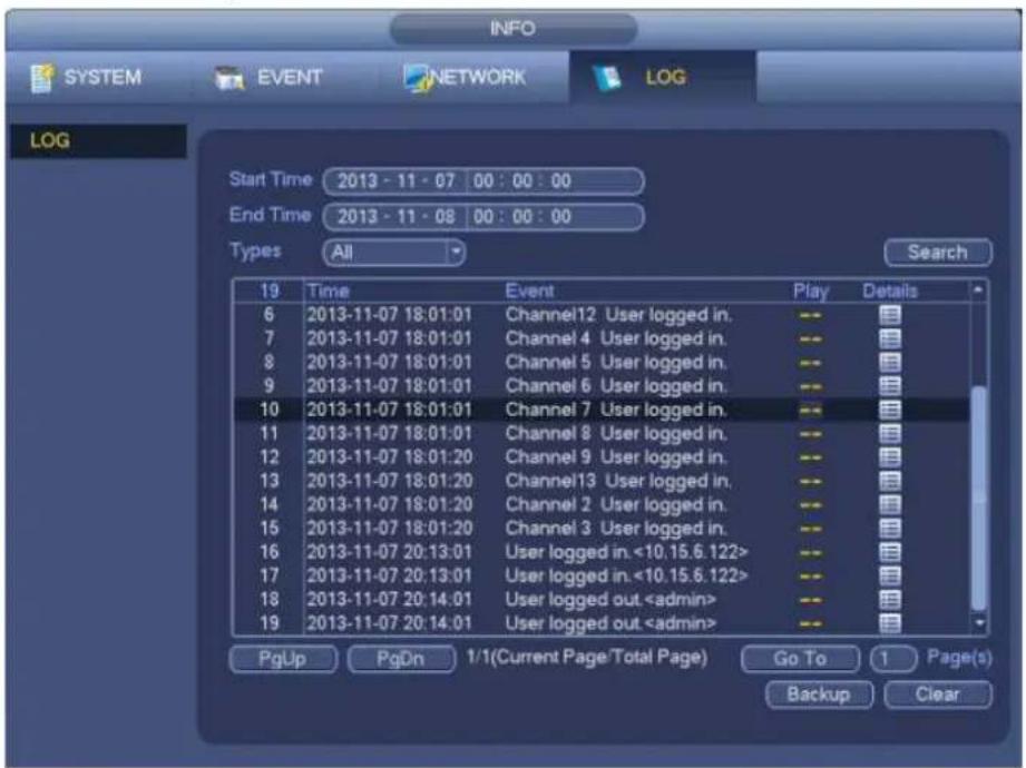
text_image
INFO SYSTEM EVENT NETWORK(LOG LOG Start Time 2013 - 11 - 07 00 : 00 : 00 End Time 2013 - 11 - 08 00 : 00 : 00 Types All Search 19 Time Event Play Details 6 2013-11-07 18:01:01 Channel12 User logged in. -- 7 2013-11-07 18:01:01 Channel 4 User logged in. -- 8 2013-11-07 18:01:01 Channel 5 User logged in. -- 9 2013-11-07 18:01:01 Channel 6 User logged in. -- 10 2013-11-07 18:01:01 Channel 7 User logged in. -- 11 2013-11-07 18:01:01 Channel 8 User logged in. -- 12 2013-11-07 18:01:20 Channel 9 User logged in. -- 13 2013-11-07 18:01:20 Channel13 User logged in. -- 14 2013-11-07 18:01:20 Channel 2 User logged in. -- 15 2013-11-07 18:01:20 Channel 3 User logged in. -- 16 2013-11-07 20:13:01 User logged in. <10.15.6.122> 17 2013-11-07 20:13:01 User logged in. <10.15.6.122> 18 2013-11-07 20:14:01 User logged outFigure 4-167
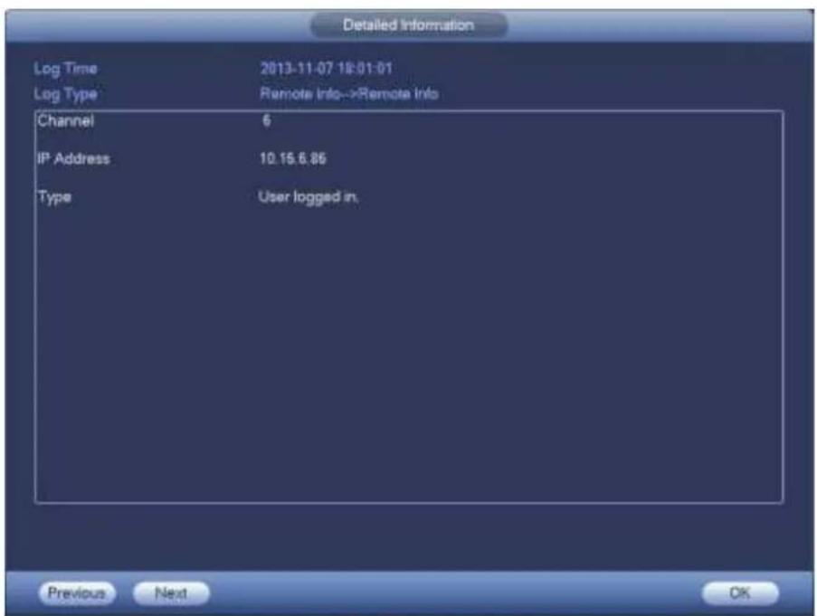
text_image
Detailed Information Log Time 2013-11-07 18:01:01 Log Type Remote Info-->Remote Info Channel 6 IP Address 10.15.6.86 Type User logged in. Previous Next OKFigure 4-168
4.17.3 Voice
Note
This function is for some series product only.
The audio function is to manage audio files and set schedule play function. It is to realize audio broadcast activation function.
4.17.3.1.1 File Manage
Here you can add audio file, listen to the audio file, or rename/delete audio file. Here you can also set audio volume. See Figure 4-169.
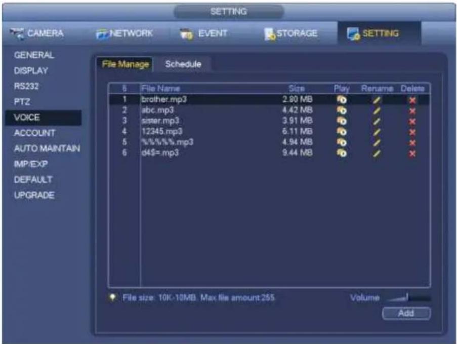
text_image
CAMERA NETWORK EVENT STORAGE SETTING GENERAL DISPLAY RS232 PTZ VOICE ACCOUNT AUTO MAINTAIN IMP/EXP DEFAULT UPGRADE File Manage Schedule 5 File Name Size Play Rename Delete 1 brother.mp3 2.80 MB ✓ ✓ ✗ 2 abc.mp3 4.42 MB ✓ ✓ ✗ 3 sister.mp3 3.91 MB ✓ ✓ ✗ 4 12345.mp3 6.11 MB ✓ ✓ ✗ 5 %%%%mp3 4.94 MB ✓ ✓ ✗ 6 d4$=mp3 9.44 MB ✓ ✓ ✗ File size: 10K-10MB Max file amount 255 Volume AddFigure 4-169
Click Add button, you can add audio file and import the audio file via the USB device. The audio file format shall be MP3 or PCM. See Figure 4-170.

Important
The audio file shall be saved on the USB device. You need to connect the USB device all the time; otherwise, the audio link function may fail. So, if you want to use the audio trigger function, please make sure the audio file is on the UBS device and the USB device has connected to the NVR before the NVR boots up. You need to make sure the USB device connection is always there if you want to manage and use the audio file function.
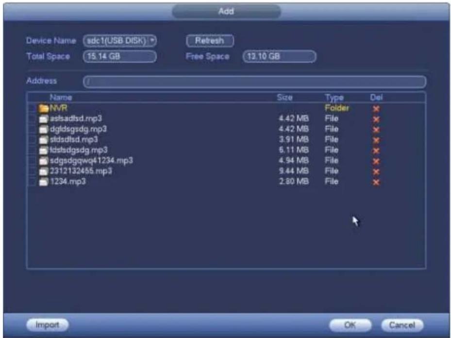
text_image
Add Device Name sdc1(USB DISK) Refresh Total Space 15.14 GB Free Space 13.10 GB Address Name Size Type Del NVR Folder ✗ aslsadltsd.mp3 4.42 MB File ✗ dgfdsgsdg.mp3 4.42 MB File ✗ stdsdltsd.mp3 3.91 MB File ✗ ldstdsgsdg.mp3 6.11 MB File ✗ sdgsdgqwq41234.mp3 4.94 MB File ✗ 2312132455.mp3 9.44 MB File ✗ 1234.mp3 2.80 MB File ✗ Import OK CancelFigure 4-170
4.17.3.1.2 Schedule
It is to set schedule broadcast function. You can play the different audio files in the specified periods. See Figure 4-171.
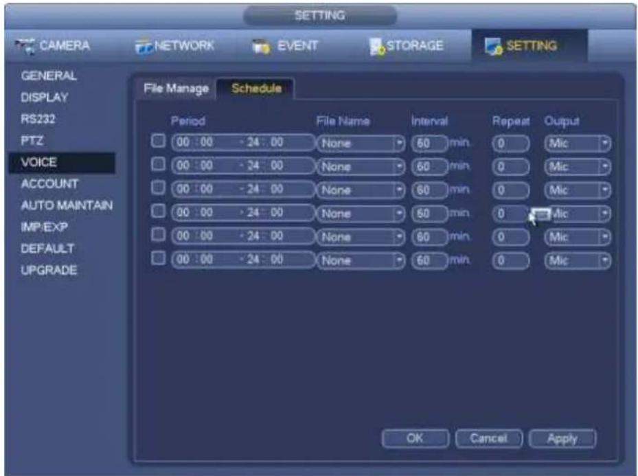
text_image
CAMERA NETWORK EVENT STORAGE SETTING GENERAL DISPLAY RS232 PTZ VOICE ACCOUNT AUTO MAINTAIN IMPIEXP DEFAULT UPGRADE File Manage Schedule Period File Name Interval Repeat Output 00:00 - 24:00 None 60 min 0 Mic 00:00 - 24:00 None 60 min 0 Mic 00:00 - 24:00 None 60 min 0 Mic 00:00 - 24:00 None 60 min 0 Mic 00:00 - 24:00 None 60 min 0 Mic 00:00 - 24:00 None 16 Min 0 Mic OK Cancel ApplyFigure 4-171
4.17.4 Account
Here is for you to implement account management. See Figure 4-172. Here you can:
- Add new user
- Modify user
- Add group
- Modify group
- Modify password.
For account management please note:
- For the user account name and the user group, the string max length is 6-byte. The backspace in front of or at the back of the string is invalid. There can be backspace in the middle. The string includes the valid character, letter, number, underline, subtraction sign, and dot.
- The default user amount is 64 and the default group amount is 20. System account adopts two-level management: group and user. No limit to group or user amount.
- For group or user management, there are two levels: admin and user.
- The user name and group name can consist of eight bytes. One name can only be used once. There are three default users: admin/888888 and hidden user "default".
- Hidden user "default" is for system interior use only and can not be deleted. When there is no login user, hidden user "default" automatically login. You can set some rights such as monitor for this user so that you can view some channel view without login.
● One user should belong to one group. User right can not exceed group right. - About reusable function: this function allows multiple users use the same account to login.
- About user account and MAC. When you add a new user, you can input the MAC address of current user. Only the user of the same MAC address can access the device remotely.(MAC address is for the device of the same LAN.) If you leave MAC address item in blank when you add a new user, the user of any MAC address can access the device remotely. You can set or change MAC address when you add or modify a user. The MAC address function is also valid for PSS login. Please note current function does not support IPV6.
After all the setups please click save button, system goes back to the previous menu.
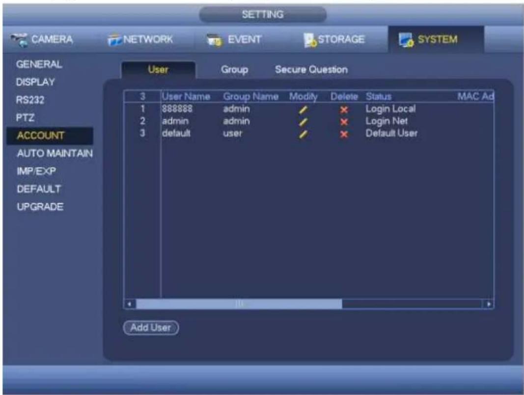
text_image
SETTING CAMERA NETWORK EVENT STORAGE SYSTEM GENERAL DISPLAY RS232 PTZ ACCOUNT AUTO MAINTAIN IMP/EXP DEFAULT UPGRADE User Group Secure Question 3 User Name Group Name Modify Delete Status MAC Ad 1 888888 admin ✓ ✗ Login Local 2 admin admin ✓ ✗ Login Net 3 default user ✓ ✗ Default User Add UserFigure 4-172
4.17.4.1.1 Add User
Click modify user button in Figure 4-172, the interface is shown as in Figure 4-173.
Please input the user name, password, select the group it belongs to from the dropdown list.
Then you can check the corresponding rights for current user.
For convenient user management, usually we recommend the general user right is lower than the admin account.
- Username: admin. Password: admin. (administrator, local and network)
- Username: 888888. Password: 888888. (administrator, local only)
- Username: default. Password: default (hidden user). Hidden user "default" is for system interior use only and can not be deleted. When there is no login user, hidden user "default" automatically login. You can set some rights such as monitor for this user so that you can view some channels without login.
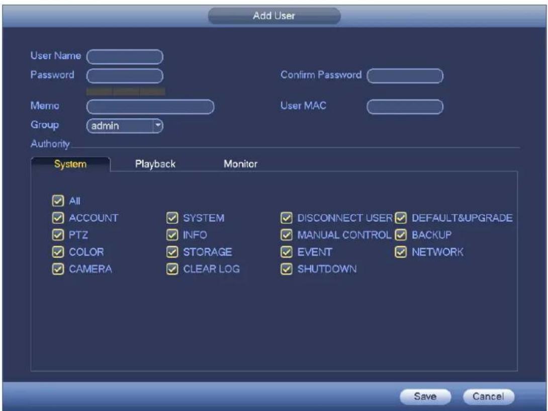
text_image
Add User User Name Password Confirm Password Memo User MAC Group admin Authority System Playback Monitor ✓ All ✓ ACCOUNT SYSTEM DISCONNECT USER DEFAULT&UPGRADE ✓ PTZ INFO MANUAL CONTROL BACKUP ✓ COLOR STORAGE EVENT NETWORK ✓ CAMERA CLEAR LOG SHUTDOWN Save CancelFigure 4-173
When you create a new user, you can input the corresponding MAC address of current user. If you leave this item in blank, any MAC address user can share this user account to login. Please note system needs to check the validity of MAC. Only the 12-digit 0-f format address can pass the validity verification. System only saves small character even you input capitalized one. You can see the corresponding prompt if there is any illegal input.
Click the Set button after the period, you can set valid period to use current account. See Figure 4-174.
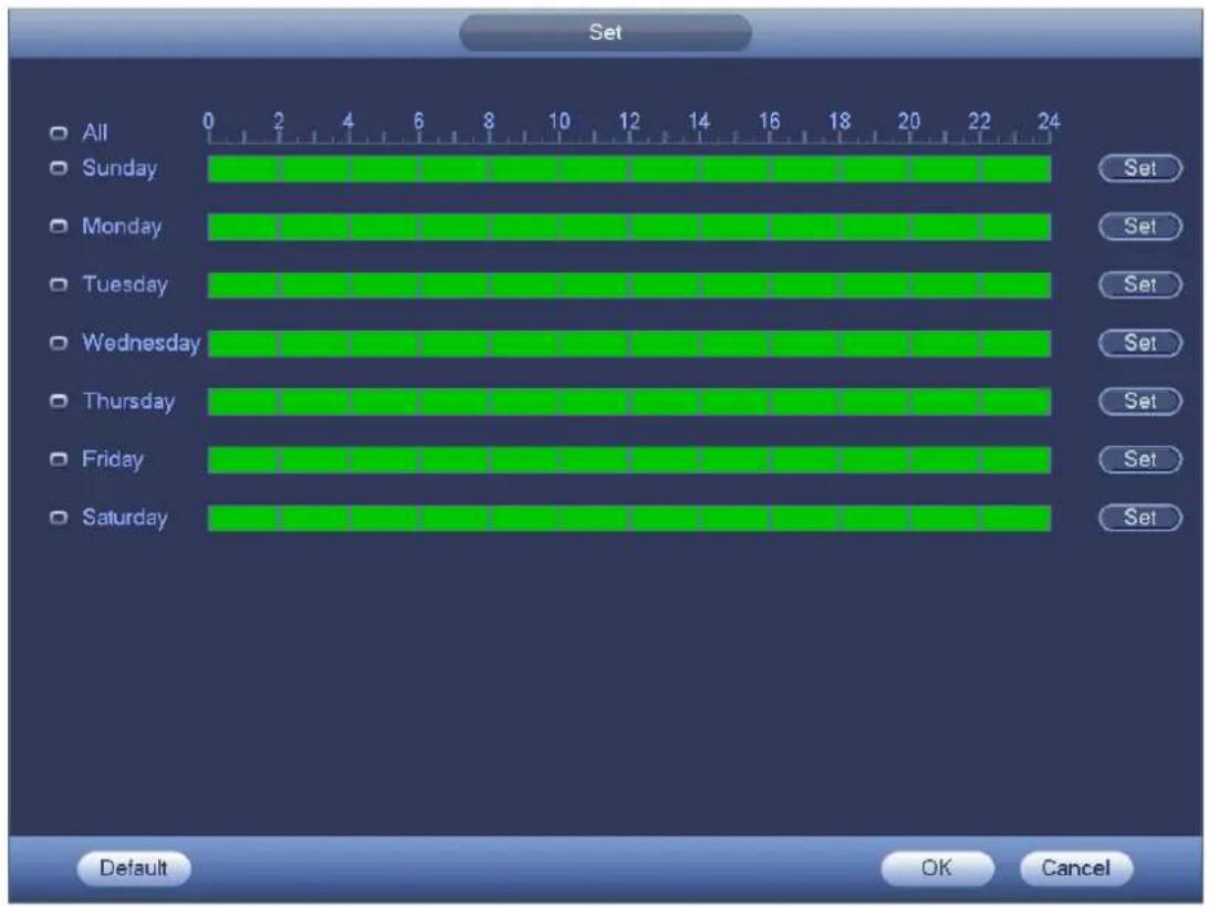
text_image
Set All Sunday Monday Tuesday Wednesday Thursday Friday Saturday 0 2 4 6 8 10 12 14 16 18 20 22 24 Set Set Set Set Set Set Set Default OK CancelFigure 4-174
Click Set button, you can set six periods in one day. See Figure 4-175. Check the box after the period, you can enable current setup.
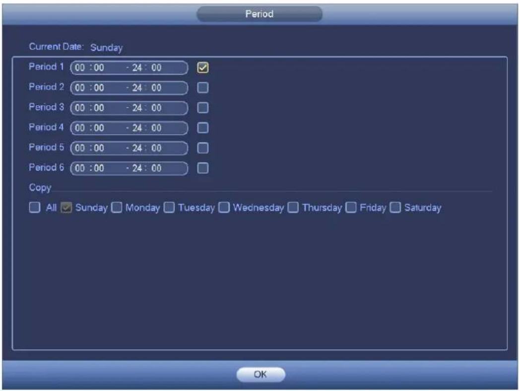
text_image
Period Current Date: Sunday Period 1 00 : 00 - 24 : 00 ✓ Period 2 00 : 00 - 24 : 00 Period 3 00 : 00 - 24 : 00 Period 4 00 : 00 - 24 : 00 Period 5 00 : 00 - 24 : 00 Period 6 00 : 00 - 24 : 00 Copy All Sunday Monday Tuesday Wednesday Thursday Friday Saturday OKFigure 4-175
4.17.4.1.2 Modify user
Click, you can go to the following interface to change user information. See Figure 4-176. For admin, 888888, and default (hidden user), you can not change period setup.
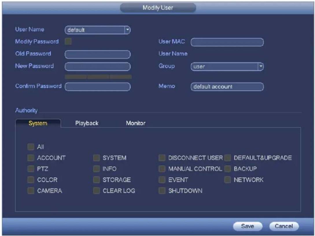
text_image
Modify User User Name default Modify Password Old Password New Password Confirm Password User MAC User Name Group user Memo default account Authority System Playback Monitor All ACCOUNT SYSTEM DISCONNECT USER DEFAULT&UPGRADE PTZ INFO MANUAL CONTROL BACKUP COLOR STORAGE EVENT NETWORK CAMERA CLEAR LOG SHUTDOWN Save CancelFigure 4-176
4.17.4.1.3 Change Password
In Figure 4-176, check the Modify password box, you can change password. Please input old password, and then input new password twice to confirm.
The password can contain 32-byte and the space at the begin or at the end of the password are null. It can contain in the middle of the password. For the user of account right, it can change the password of other users.
4.17.4.1.4 Add/Modify Group
In Figure 4-172, click Group button, you can see the following interface. See Figure 4-177.
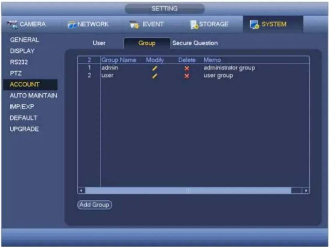
text_image
SETTING CAMERA NETWORK EVENT STORAGE SYSTEM GENERAL DISPLAY RS232 PTZ ACCOUNT AUTO MAINTAIN IMP/EXP DEFAULT UPGRADE User Group Secure Question 2 Group Name Modify Delete Memo 1 admin / * administrator group 2 user / * user group Add GroupFigure 4-177
Click add group button in Figure 4-177, the interface is shown as below. See Figure 4-178.
Here you can input group name and then input some memo information if necessary.
There are total 98 rights such as control panel, shut down, real-time monitor, playback, record, record file backup, PTZ, user account, system information view, alarm input/output setup, system setup, log view, clear log, upgrade system, control device and etc.
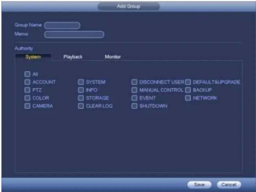
text_image
Add Group Group Name Memo Authority System Playback Monitor All ACCOUNT SYSTEM DISCONNECT USER DEFAULTSUPGRADE PTZ/INFO MANUAL CONTROL BACKUP COLOR STORAGE EVENT NETWORK CAMERA CLEAR LOG SHUTDOWN Save CancelFigure 4-178
4.17.4.1.5 Security Question
The security question is shown as below. See Figure 4-179.
Here you can change security questions.
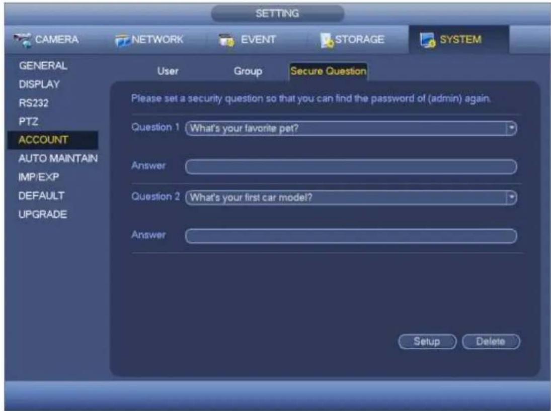
text_image
SETTING CAMERA NETWORK EVENT STORAGE SYSTEM GENERAL DISPLAY RS232 PTZ ACCOUNT AUTO MAINTAIN IMP/EXP DEFAULT UPGRADE User Group Secure Question Please set a security question so that you can find the password of (admin) again. Question 1 What's your favorite pet? Answer Question 2 What's your first car model? Answer Setup DeleteFigure 4-179
4.17.5 Update
4.17.5.1 Local Update
From Mani menu->Setting->Info->Update, you can go to the following interface. See Figure 4-180.
a) Insert USB device that contain the upgrade file.
b) Click Start button and then select the .bin file.
c) You can see the corresponding dialogue box after the update process is complete.
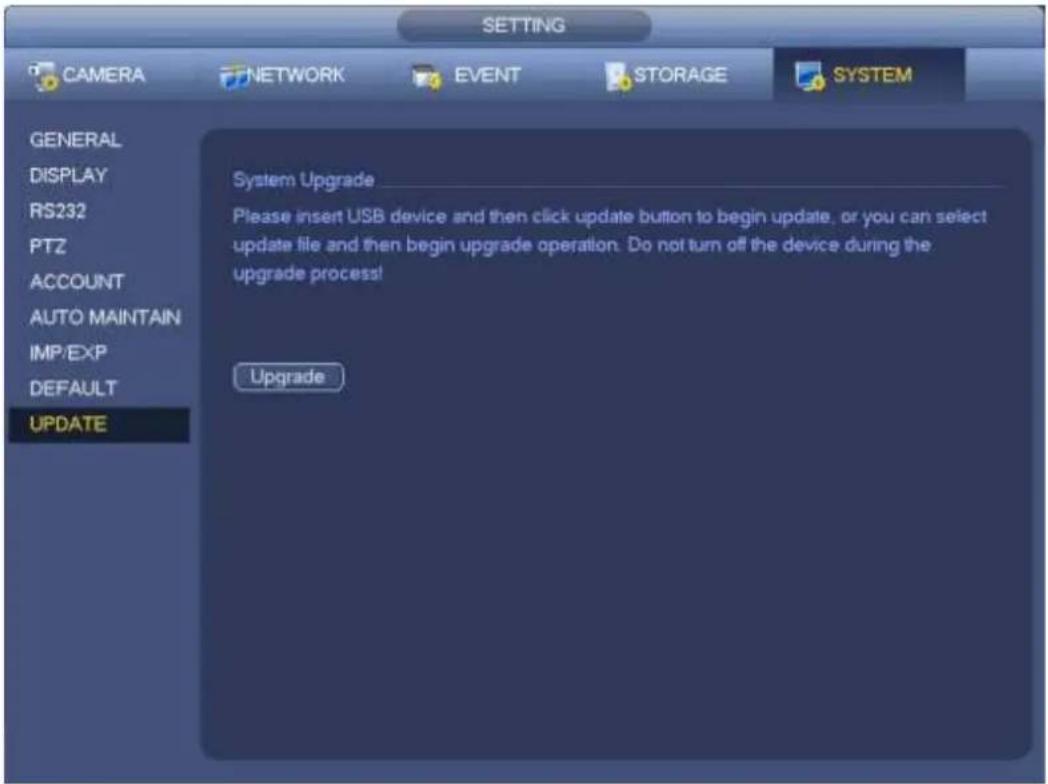
text_image
SETTING CAMERA NETWORK EVENT STORAGE SYSTEM GENERAL DISPLAY RS232 PTZ ACCOUNT AUTO MAINTAIN IMP/EXP DEFAULT UPDATE System Upgrade Please insert USB device and then click update button to begin update, or you can select update file and then begin upgrade operation. Do not turn off the device during the upgrade process! UpgradeFigure 4-180
4.17.5.2 Uboot
When device is booting up, it can auto detect the USB device and the update file on it. It can auto update once there is proper upgrade file.

Important
- USB device root directory shall have "u-boot.bin.img" and "update.img" files. USB device shall be FAT32 mode.
- For 4X series product, it only updates "update.img". The "update.img" shall be renamed as "recovery.img" and is saved on the root directory.
- USB device shall be on the USB 2.0 port, otherwise device can not detect or update.
4.17.6 Default
You can restore factory default setup to fix some problems when the device is running slowly. Configuration error occurred.
From Main menu->Setting->System->Default, you can go to the default interface. See Figure 4-181.
Click default icon, system pops up a dialogue box. You can highlight to restore factory default setup.
All
- Camera
- Network
- Event
- Storage
- System
Please highlight icon to select the corresponding function.
After all the setups please click OK button, system goes back to the previous menu.
Warning!
After you use default function, some your customized setup may lose forever! Please think twice before you begin the operation!
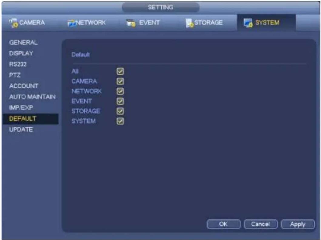
text_image
SETTING CAMERA NETWORK EVENT STORAGE SYSTEM GENERAL DISPLAY RS232 PTZ ACCOUNT AUTO MAINTAIN IMP/EXP DEFAULT UPDATE Default All CAMERA NETWORK EVENT STORAGE SYSTEM OK Cancel ApplyFigure 4-181
4.17.7 RS232
From Main menu->Setting->System->RS232, RS232 interface is shown as below. There are five items.
See Figure 4-182.
- Function: There are various devices for you to select. Console is for you to use the COM or mini-end software to upgrade or debug the program. The control keyboard is for you to control the device via the special keyboard. Transparent COM (adapter) is to connect to the PC to transfer data directly. Protocol COM is for card overlay function. Network keyboard is for you to use the special keyboard to control the device. PTZ matrix is to connect to the peripheral matrix control.
● Baud rate: You can select proper baud rate.
● Data bit: You can select proper data bit. The value ranges from 5 to 8. - Stop bit: There are three values: 1/1.5/2.
● Parity: there are five choices: none/odd/even/space mark.
System default setup is: - Function: Console
● Baud rate:115200 - Data bit:8
- Stop bit:1
- Parity: None
After completing all the setups please click save button, system goes back to the previous menu.
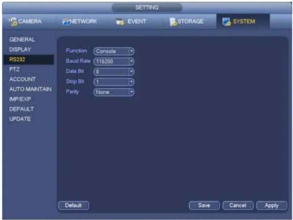
text_image
SETTING CAMERA NETWORK EVENT STORAGE SYSTEM GENERAL DISPLAY RS232 PTZ ACCOUNT AUTO MAINTAIN IMP/EXP DEFAULT UPDATE Function Console Baud Rate 115200 Data Bit 8 Stop Bit 1 Parity None Default Save Cancel ApplyFigure 4-182
4.17.8 Auto Maintain
Here you can set auto-reboot time and auto-delete old files setup. You can set to delete the files for the specified days. See Figure 4-183.
You can select proper setup from dropdown list.
After all the setups please click save button, system goes back to the previous menu.
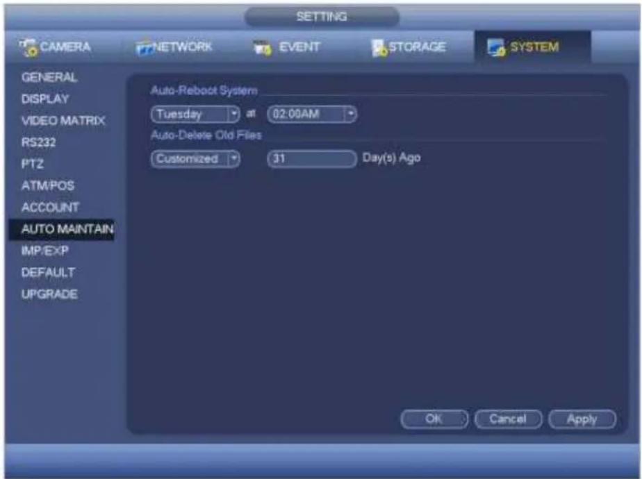
text_image
CAMERA NETWORK EVENT STORAGE SYSTEM GENERAL DISPLAY VIDEO MATRIX RS232 PT2 ATM/POS ACCOUNT AUTO MAINTAIN IMP/EXP DEFAULT UPGRADE Auto-Reboot System Tuesday at 02:00AM Auto-Delete Old Files Customized 31 Day(s) Ago OK Cancel ApplyFigure 4-183
4.17.9 Logout /Shutdown/Restart
From Mani menu->Operation->Shutdown, you can see an interface shown as in Figure 4-184.
- Shutdown: System shuts down and turns off power.
- Logout: Log out menu. You need to input password when you login the next time.
- Restart: reboot device.
If you shut down the device, there is a process bar for your reference, system waits for 3 seconds and then shut down (You can not cancel).
Please note, sometimes you need to input the proper password to shut down the device.
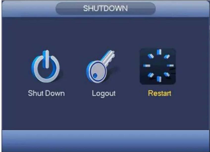
text_image
SHUTDOWN Shut Down Logout RestartFigure 4-184
5 Web Operation
5.1 General Introduction
The device web provides channel monitor menu tree, search, alarm setup, system setup, PTZ control and monitor window and etc.
Important
The following operation is based on 32-channel series device.
5.1.1 Preparation
Before log in, please make sure:
● Network connection is right
- NVR and PC network setup is right. Please refer to network setup(main
- menu->setting->network)
- Use order ping ***.***.***.***(* NVR IP address) to check connection is OK or not. Usually the return TTL value should be less than 255.
- Open the IE and then input NVR IP address.
- System can automatically download latest web control and the new version can overwrite the previous one.
About PoE address setup, operation and allocation.
1) Insert PoE
After you insert PoE, device may try to set a corresponding IP address of the Switch network adapter. First, system tries to set via arp ping. It then uses DHCP if it finds the DHCP is enabled. After successfully set IP address, system may use Switch to send out broadcast, system considers the connection is OK when there is any response. Now system is trying to login the newly found IPC. Now please check the interface, you can see the corresponding digital channel is active now. You can see a small PoE icon at the top left corner. You can see the PoE channel, PoE port information and etc from the connection list of the remote device interface (Chapter 4.5). For the IP search list, you need to click the IP search to display or refresh.
2) Remove PoE
After you removed PoE, you can see the corresponding digital channel becomes idle (disable). On the remote device interface, it is removed from the connected list. For the IP search list, you need to click the IP search to refresh.
3) After you insert PoE, system follows the principles listed below to map channel.
a) If it is your first time to insert PoE, system can map it to the first idle channel. After map, the channel can memorize the MAC address of the IPC. It is a
b) If it is your second time to insert the PoE, system can check the saved MAC address according to
c) Thirdly, according to the
d) Fourthly, system goes to find the first idle channel it can get.
Generally speaking, once you insert PoE, system follow the steps listed above to find the channel available.
4) When you insert PoE, all channels are in use now.
System can pop up a dialogue box for you to select a channel to overwrite. The title of the pop-up interface is the name of the current operation PoE port. In this interface, All PoE channel become grey and can not select.
5.1.2 Log in
Open the IE and then input the NVR IP address in the address column.
For example, if your NVR IP address is 192.168.1.108, then please input http://192.168.1.108 in IE address column. See Figure 5-1.
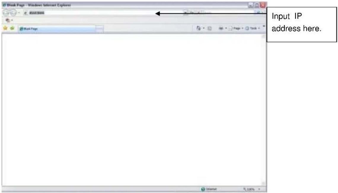
text_image
Input IP address here.Figure 5-1
System pops up warning information to ask you whether install Web plug-in or not. Please click yes button.
If you can't download the ActiveX file, please modify your settings as follows. See Figure 5-2.
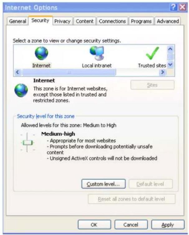
text_image
Internet Options General Security Privacy Content Connections Programs Advanced Select a zone to view or change security settings. Internet Local intranet Trusted sites Internet This zone is for Internet websites, except those listed in trusted and restricted zones. Security level for this zone Allowed levels for this zone: Medium to High Medium-high - Appropriate for most websites - Prompts before downloading potentially unsafe content - Unsigned ActiveX controls will not be downloaded Custom level... Default level Reset all zones to default level OK Cancel Apply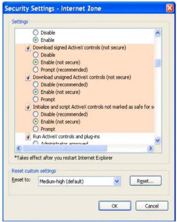
text_image
Security Settings - Internet Zone Settings Disable Enable Download signed ActiveX controls (not secure) Disable Enable (not secure) Prompt (recommended) Download unsigned ActiveX controls (not secure) Disable (recommended) Enable (not secure) Prompt Initialize and script ActiveX controls not marked as safe for s Disable (recommended) Enable (not secure) Prompt Run ActiveX controls and plug-ins Administrator approved *Takes effect after you restart Internet Explorer Reset custom settings Reset to: Medium-high (default) Reset... OK CancelFigure 5-2
After installation, the interface is shown as below. See Figure 5-3.
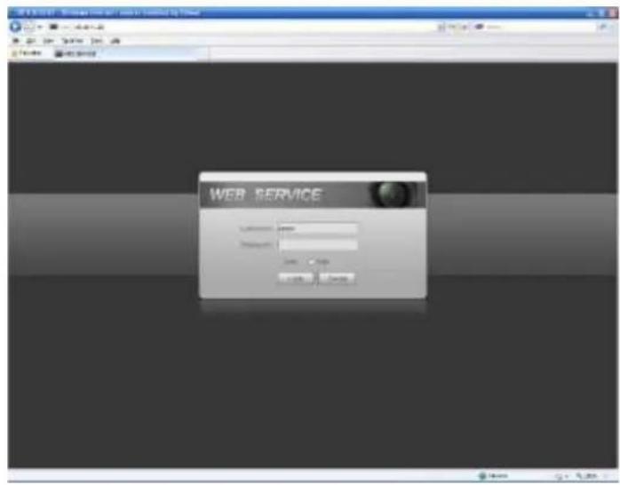
text_image
WEB SERVICE User name: 12345 Description: OK Cancel Cancel ApplyFigure 5-3
Please input your user name and password.
Default factory name is admin and password is admin.
Note: For security reasons, please modify your password after you first login.
5.2 LAN Mode
For the LAN mode, after you logged in, you can see the main window. See Figure 5-9.
This main window can be divided into the following sections.
- Section 1: there are six function buttons: Live (chapter 0), setup (chapter 5.8), info (Chapter 5.9), playback (chapter 5.10), alarm (chapter 5.11), and logout (chapter 5.12).
- Section 2: There are monitor channels successfully connected to the NVR.
Please refer to Figure 5-4 for main stream and extra stream switch information.
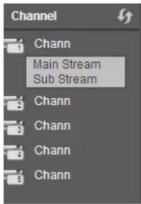
text_image
Channel 1 Chann Main Stream Sub Stream 2 Chann 3 Chann 4 Chann 5 ChannFigure 5-4
- Section 3: Open all. Open all button is to enable/disable all-channel real-time monitor. Here you can select main stream/sub stream too. See Figure 5-5.
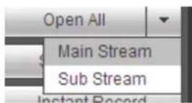
text_image
Open All Main Stream Sub Stream Instant RecordFigure 5-5
- Section 4: Start Talk button.
You can click this button to enable audio talk. Click 【▼】 to select bidirectional talk mode. There are four options: DEFAULT, G711a, G711u and PCM. See Figure 5-6.
After you enable the bidirectional talk, the Start talk button becomes End Talk button and it becomes yellow. Please note, if audio input port from the device to the client-end is using the first channel audio input port. During the bidirectional talk process, system will not encode the audio data from the 1-channel.
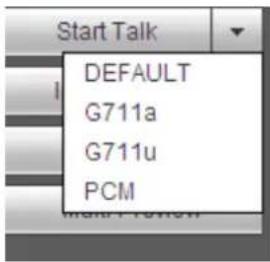
text_image
Start Talk DEFAULT G711a G711u PCMFigure 5-6
- Section 5: Instant record button. Click it, the button becomes yellow and system begins manual record. See Figure 5-7. Click it again, system restores previous record mode.
Figure 5-7
- Section 6: Local play button.
The Web can playback the saved (Extension name is dav) files in the PC-end.
Click local play button, system pops up the following interface for you to select local play file. See Figure 5-8.
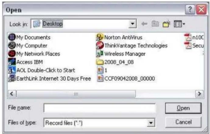
text_image
Open Look in: Desktop My Documents My Computer My Network Places Access IBM AOL Double-Click to Start EarthLink Internet 30 Days Free Norton AntiVirus ThinkVantage Technologies Wireless Manager 2008_04_08 1 CCF09042008_00000 n100 Secu File name: Files of type: Record files (*.*)Figure 5-8
● Section 7: Zero-channel encoding. Please refer to chapter 5.6 for detailed information.
- Section 8: PTZ operation panel. Please refer to chapter 5.4 for detailed information.
- Section 9: Image setup and alarm setup. Please refer to chapter 5.5 for detailed information.
- Section 10: From the left to the right, you can see video quality/fluency/full screen/1-window/4-window/6-window/8-window/9-window/13-window/16-window/20-window/25-window/36-window.. You can set video fluency and real-time feature priority.
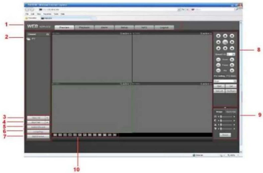
text_image
1 WEB SERVICE 2 3 4 5 6 7 8 9 10Figure 5-9
5.3 Real-time Monitor
In section 2, left click the channel name you want to view, you can see the corresponding video in current window.
On the top left corner, you can view device IP(172.11.10.11), channel number(1), network monitor bit stream(2202Kbps) and stream type(M=main stream, S=sub stream). See Figure 5-10.
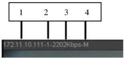
text_image
1 2 3 4 172.11 10.111-1-2202Kbps-MFigure 5-10
On the top right corner, there are six unction buttons. See Figure 5-11.
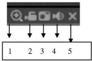
text_image
1 2 3 4 5Figure 5-11
- 1: Digital zoom: Click this button and then left drag the mouse in the zone to zoom in. right click mouse system restores original status.
- 2: Local record. When you click local record button, the system begins recording and this button becomes highlighted. You can go to system folder RecordDownload to view the recorded file.
- 3: Snapshot picture. You can snapshot important video. All images are memorized in system client folder PictureDownload (default).
● 4: Audio :Turn on or off audio.(It has no relationship with system audio setup ) - 5: Close video.
5.4 PTZ
Before PTZ operation, please make sure you have properly set PTZ protocol. (Please refer to chapter 5.8.5.10).
There are eight direction keys. In the middle of the eight direction keys, there is a 3D intelligent positioning key.
Click 3D intelligent positioning key, system goes back to the single screen mode. Drag the mouse in the screen to adjust section size. It can realize PTZ automatically.
Please refer to the following sheet for PTZ setup information.
| Parameter | Function |
| Scan | Select Scan from the dropdown list.Click Set button, you can set scan left and right limit.Use direction buttons to move the camera to you desired location and then click left limit button. Then move the camera again and then click right limit button to set a right limit. |
| Preset | Select Preset from the dropdown list.Turn the camera to the corresponding position and Input the preset value. Click Add button to add a preset. |
| Tour | Select Tour from the dropdown list.Input preset value in the column. Click Add preset button, you have added one preset in the tour.Repeat the above procedures you can add more presets in one tour.Or you can click delete preset button to remove one preset from the tour. |
| Pattern | Select Pattern from the dropdown list.You can input pattern value and then click Start button to begin PTZ movement such as zoom, focus, iris, direction and etc. Then you can click Add button to set one pattern. |
| Aux | Please input the corresponding aux value here.You can select one option and then click AUX on or AUX off button. |
| Light and wiper | You can turn on or turn off the light/wiper. |
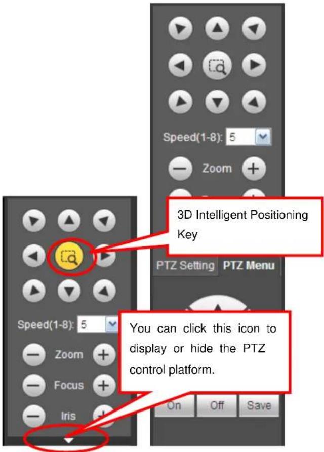
text_image
3D Intelligent Positioning Key PTZ Setting PTZ Menu You can click this icon to display or hide the PTZ control platform. On Off SaveFigure 5-12
5.5 Image/Alarm-out
Select one monitor channel video and then click Image button in section 9, the interface is shown as Figure 5-13.
5.5.1 Image
Here you can adjust its brightness, contrast, hue and saturation. (Current channel border becomes green).
Or you can click Reset button to restore system default setup.
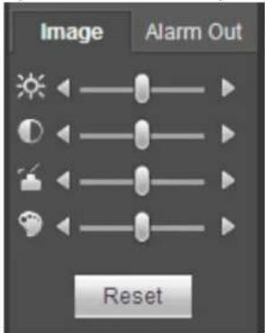
text_image
Image Alarm Out ResetFigure 5-13
5.5.2 Alarm output
Here you can enable or disable the alarm signal of the corresponding port. See Figure 5-14.
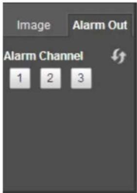
text_image
Image Alarm Out Alarm Channel 1 2 3Figure 5-14
5.6 Zero-channel Encode
Select a window and then click zero-channel encode button, the interface is shown as below. See Figure 5-15.
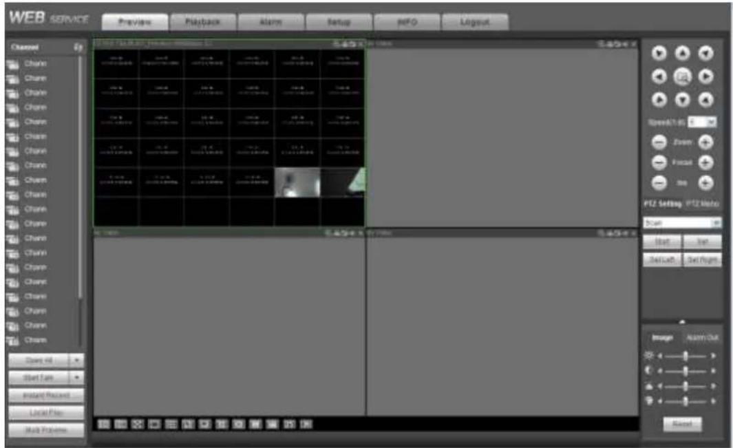
text_image
WEB SERVICE Preview Playback Alarm Setup ePO Layout Channel Chain Chain Chain Chain Chain Chain Chain Chain Chain Chain Chain Chain Chain Chain Chain Chain Chain Chain Chain Chain Chain Chain Chain Chain Chain Chain Chain Chain Chain Chain Chain Chain Chain Chain Chain Chain Chain Chain Chain Chain Chain Chain Chain Chain Chain Chain Chain Chain Chain Chain Channel Start Time Instant Record Local Plan Multi Programs 100 100 100 100 100 100 100 100 100 100 100 100 100 100 100 100 100 100 100 100 100 100 100 100 100 100 2.5x 2.5x 2.5x 2.5x 2.5x 2.5x 2.5x 2.5x 2.5x 2.5x 2.5x 2.5x 2.5x 2.5x 2.5x 2.5x 2.5x 2.5x 2.5x 2.5x 2.5x 3.5x 3.5x 3.5x 3.5x 3.5x 3.5x 3.5x 3.5x 3.5x 3.5x 3.5x 3.5x 3.5x 3.5x 3.5x 3.5x 3.5x 3.5x 3.5x 4.5x 4.5x 4.5x 4.5x 4.5x 4.5x 4.5x 4.5x 4.5x 4.5x 4.5x 4.5x 4.5x 4.5x 4.5x 4.5x 4.5x 5.5x 5.5x 5.5x 5.5x 5.5x 5.5x 5.5x 5.5x 5.5x 5.5x 5.5x 5.5x 5.5x 5.5x 6.5x 6.5x 6.5x 6.5x 6.5x 6.5x 6.5x 6.5x 6.5x 6.5x 6.5x 6.5x 6.5x 7.5x 7.5x 7.5x 7.5x 7.5x 7.5x 7.5x 7.5x 7.5x 7.5x 7.5x 7.5x 7.5x 8.5x 8.5x 8.5x 8.5x 8.5x 8.5x 8.5x 8.5x 8.5x 8.5x 8.5x 9.5x 9.5x 9.5x 9.5x 9.5x 9.5x 9.5x 9.5x 9.5x 9.5x 10.5x10.5x10.5x10.5x10.5x10.5x10.5x10.5x10.5x10.5x10.5x10.5x10.5x10.5k 11k11k11k11k11k11k11k11k11k11k11k11k11k11k11k11k11k11k11k11k11k11k11k11k11k11k11k11k11k11k11kFigure 5-15
5.7 WAN Login
In WAN mode, after you logged in, the interface is shown as below. See Figure 5-16.
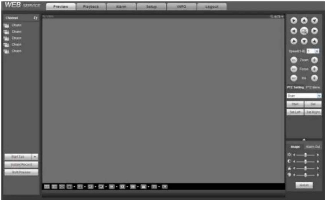
text_image
WEB SERVICE Preview Playback Alarm Setup INFO Logout Channel Cham Cham Cham Cham Channel Start Time Instant Record Multi Practice Speed(1-8) Zoom Focus ms PTZ Setting: PTZ Menu Scan Start Out Set Left Set Right Image Alarm Out BackFigure 5-16
Please refer to the following contents for LAN and WAN login difference.
1) In the WAN mode, system opens the main stream of the first channel to monitor by default. The open/close button on the left pane is null.
2) You can select different channels and different monitor modes at the bottom of the interface. See
Figure 5-17.
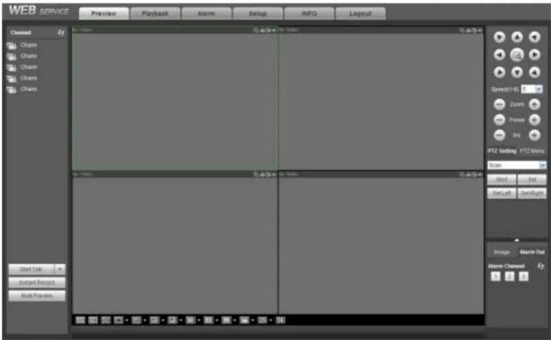
text_image
WEB SERVICE Preview Playback Alarms Setup RINFO Layout Channel Chain Chalk Chalk Chalk Chalk Chalk Start Task Instant Record Multi-Preview Start Time End Time Start Time End Time Spread 1:00 Zoom Focus Pos PTZ Setting PTZ Menu Scan Start Exit Set Left Set Right Image Alarm Out Alarm Channel 0Figure 5-17
Important
The window display mode and the channel number are by default. For example, for the 16-channel, the max window split mode is 16.
3) Multiple-channel monitor, system adopts extra stream to monitor by default. Double click one channel, system switches to single channel and system uses main stream to monitor. You can view there are two icons at the left top corner of the channel number for you reference. M stands for main stream. S stands for sub stream (extra stream).
4) If you login via the WAN mode, system does not support alarm activation to open the video function in the Alarm setup interface.
Important
- For multiple-channel monitor mode, system adopts extra stream to monitor by default. You can not modify manually. All channels are trying to synchronize. Please note the synchronization effect still depends on your network environments.
- For bandwidth consideration, system can not support monitor and playback at the same time. System auto closes monitor or playback interface when you are searching setup in the configuration interface. It is to enhance search speed.
5.8 Setup
5.8.1 Camera
5.8.1.1 Remote Device
Remote device interface is shown as below. See Figure 5-18.
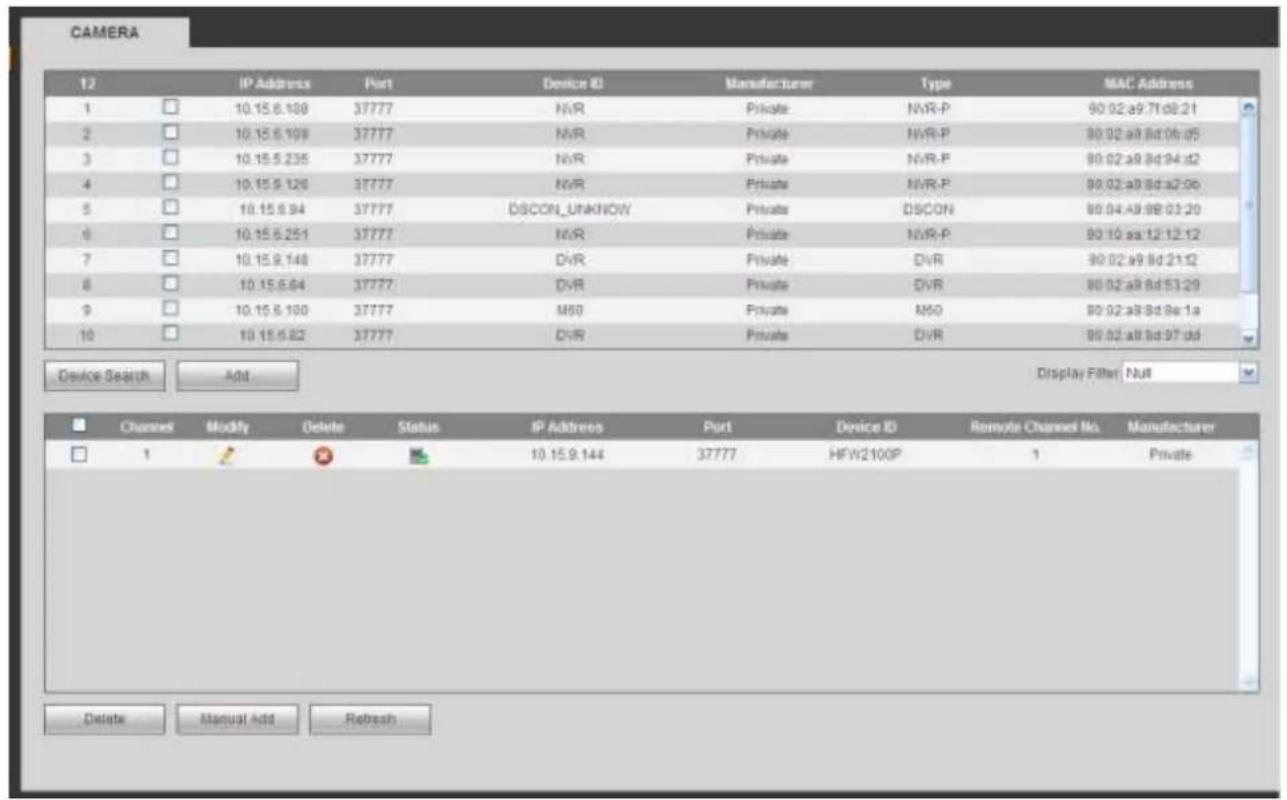
text_image
CAMERA 12 IP Address Port Device ID Manufacturer Type MAC Address 1 10.15.6.108 37777 NVR Private NVR-P 90 02 a9.71 d8:21 2 10.15.6.109 37777 NVR Private NVR-P 90 02 a9.8d 06:05 3 10.15.5.235 37777 NVR Private NVR-P 90 02 a9.8d 94:02 4 10.15.5.126 37777 NVR Private NVR-P 90 02 a9.8d a2:06 5 10.15.5.94 37777 DSCON_UNKNOWN Private DSCON 90 04 A9 9B 03:20 6 10.15.5.251 37777 NVR Private NVR-P 90 10 aa:12 12:12 7 10.15.5.148 37777 DVR Private DVR 90 02 a9.8d 21:12 8 10.15.5.64 37777 DVR Private DVR 90 02 a9.8d 53:29 9 10.15.5.100 37777 M60 Private M60 90 02 a8.8d 9e:1a 10 10.15.5.82 37777 DVR Private DVR 90 02 a8.8d 97 dd Device Search Add Display Filter Null Channel Modify Delete Status IP Address Port Device ID Remote Channel No. 1 1 10.15.9.144 37777 HFW2100P 1 Private Delete Manual Add RefreshFigure 5-18
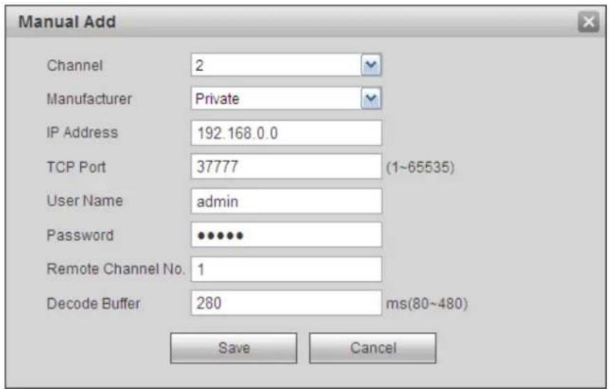
text_image
Manual Add Channel 2 Manufacturer Private IP Address 192.168.0.0 TCP Port 37777 (1~65535) User Name admin Password •••••• Remote Channel No. 1 Decode Buffer 280 ms(80~480) Save CancelFigure 5-19
Please refer to the following sheet for log parameter information.
| Parameter | Function |
| Device search | Click Device search button, you can view the searched device information on the list. It includes device IP address, port, device name, manufacturer and type. |
| Add | Select a device in the list and then click Add button, system can connect the device automatically and add it to the Added device list. Or you can double click one item in the list to add a device. |
| Modify | Click or any device in the Added device list, you can change the corresponding channel setup. |
| Delete | Click ,you can delete the remote connection of the corresponding channel. |
| Connection status | : Connection succeeded.: Connection failed. |
| Delete | Select a device in the Added device list and then click Delete button, system can disconnect the device and remove it from the Added device list. |
| Manual Add | Click it, the interface is shown as in Figure 5-19. Here you can add network camera manually.You can select a channel from the dropdown list (Here only shows disconnection channel.)Note:System supports manufactures such as Panasonic, Sony, Dynacolor, Samsung, AXIS, Arecont, Dahua and Onvif standard protocol.If you do not input IP address here. System uses default IP 192.168.0.0 and system does not connect to this IP.Can not add two devices at the same time. Click OK button here, system only connect to the corresponding device of current channel. |
5.8.1.2 Image
Note
Slight difference may be found since the connected network camera may not be same model.
Here you can view device property information. The setups become valid immediately after you set. See Figure 5-20.
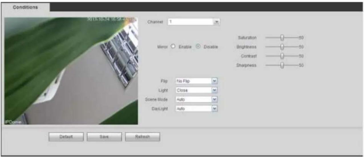
text_image
Conditions Channel 1 Mirror ○ Enable ○ Disable Saturation —— 50 Brightness —— 50 Contrast —— 50 Sharpness —— 50 Flip No Flip Light Close Scene Mode Auto DayLight Auto Default Save RefreshFigure 5-20
Please refer to the following sheet for detailed information.
| Parameter | Function | |
| Channel | Please select a channel from the dropdown list. | |
| Period | It divides one day (24 hours) to two periods. You can set different hue, brightness, and contrast for different periods. | |
| Hue | It is to adjust monitor video brightness and darkness level. The default value is 50.The bigger the value is, the large the contrast between the bright and dark section is and vice versa. | |
| Brightness | It is to adjust monitor window brightness. The default value is 50.The larger the number is , the bright the video is. When you input the value here, the bright section and the dark section of the video will be adjusted accordingly. You can use this function when the whole video is too dark or too bright. Please note the video may become hazy if the value is too high. The value ranges from 0 to 100.The recommended value ranges from 40 to 60. | |
| Contrast | It is to adjust monitor window contrast. The value ranges from 0 to 100. The default value is 50.The larger the number is, the higher the contrast is. You can use this function when the whole video bright is OK but the contrast is not proper. Please note the video may become hazy if the value is too low. If this value is too high, the dark section may lack brightness while the bright section may over exposure .The recommended value ranges from 40 to 60. | |
| Saturation | It is to adjust monitor window saturation. The value ranges from 0 to 100. The default value is 50.The larger the number is, the strong the color is. This value has no effect on the general brightness of the whole video. The video color may become too strong if the value is too high. For the grey part of the video, the distortion may occur if the white balance is not accurate. Please note the video may not be | |
| attractive if the value is too low. The recommended value ranges from 40 to 60. | ||
| Gain | The gain adjust is to set the gain value. The smaller the value is, the low the noise is. But the brightness is also too low in the dark environments. It can enhance the video brightness if the value is high. But the video noise may become too clear. | |
| White level | It is to enhance video effect. | |
| Color mode | It includes several modes such as standard, color. You can select corresponding color mode here, you can see hue, brightness, and contrast and etc will adjust accordingly. | |
| Auto Iris | It is to enable/disable auto iris function. | |
| Flip | It is to switch video up and bottom limit.This function is disabled by default. | |
| Mirror | It is to switch video left and right limit.This function is disabled by default. | |
| BLC Mode | BLC | The device auto exposures according to the environments situation so that the darkest area of the video is cleared |
| WDR | For the WDR scene, this function can lower the high bright section and enhance the brightness of the low bright section. So that you can view these two sections clearly at the same time.The value ranges from 1 to 100. When you switch the camera from no-WDR mode to the WDR mode, system may lose several seconds record video. | |
| HLC | After you enabled HLC function, the device can lower the brightness of the brightest section according to the HLC control level. It can reduce the area of the halo and lower the brightness of the whole video. | |
| Off | It is to disable the BLC function. Please note this function is disabled by default. | |
| Profile | It is to set the white balance mode. It has effect on the general hue of the video. This function is on by default.You can select the different scene mode such as auto, sunny, cloudy, home, office, night, disable and etc to adjust the video to the best quality.● Auto: The auto white balance is on. System can auto compensate the color temperature to make sure the vide color is proper.● Sunny: The threshold of the white balance is in the sunny mode.● Night: The threshold of the white balance is in the night mode.● Customized: You can set the gain of the red/blue channel. The value reneges from 0 to 100. | |
| Day/Night | It is to set device color and the B/W mode switch. The default setup is auto.● Color: Device outputs the color video.● Auto: Device auto select to output the color or the B/W | |
| video according to the device feature (The general bright of the video or there is IR light or not.)B/W: The device outputs the black and white video.Sensor: It is to set when there is peripheral connected IR light. | ||
5.8.1.3 Encode
5.8.1.3.1 Encode
The encode interface is shown as below. See Figure 5-21.
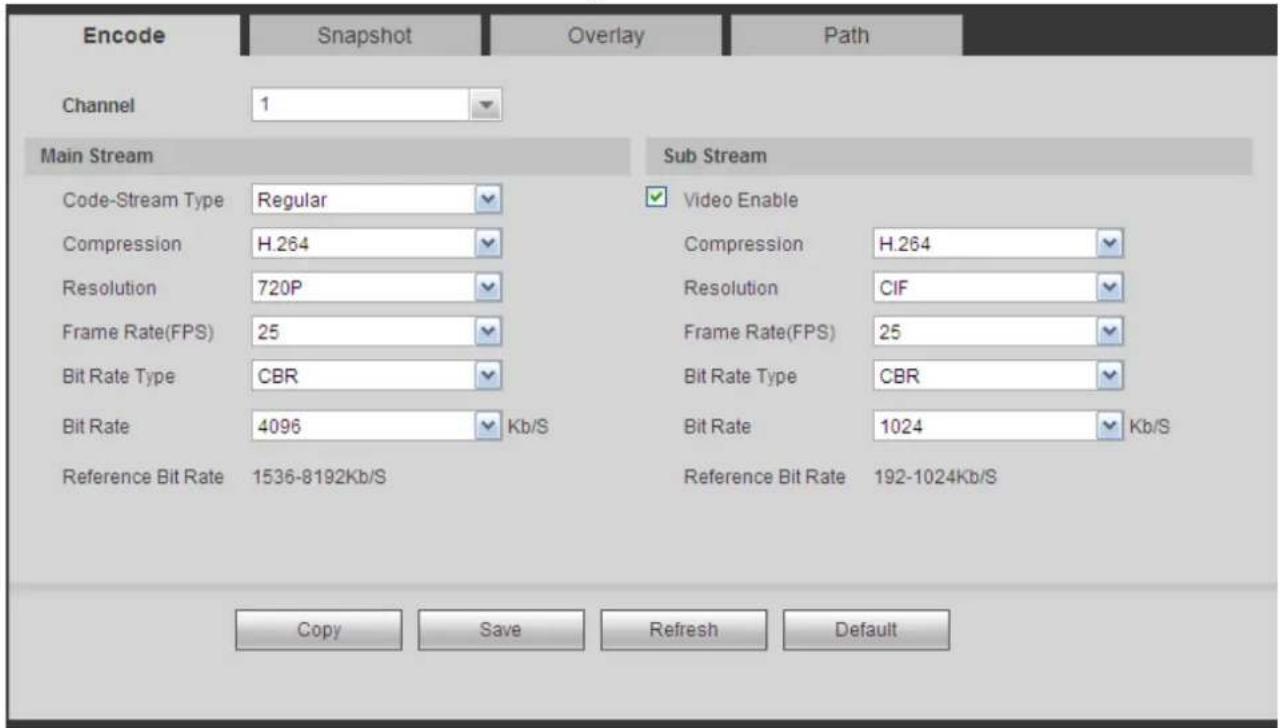
text_image
Encode Snapshot Overlay Path Channel 1 Main Stream Sub Stream Code-Stream Type Regular Video Enable Compression H.264 Compression H.264 Resolution 720P Resolution CIF Frame Rate(FPS) 25 Frame Rate(FPS) 25 Bit Rate Type CBR Bit Rate Type CBR Bit Rate 4096 Kb/S Bit Rate 1024 Kb/S Reference Bit Rate 1536-8192Kb/S Reference Bit Rate 192-1024Kb/S Copy Save Refresh DefaultFigure 5-21
Please refer to the following sheet for detailed information.
| Parameter | Function |
| Channel | Please select a channel from the dropdown list. |
| Video enable | Check the box here to enable extra stream video. This item is enabled by default. |
| Code stream type | It includes main stream, motion stream and alarm stream. You can select different encode frame rates form different recorded events.System supports active control frame function (ACF). It allows you to record in different frame rates.For example, you can use high frame rate to record important events, record scheduled event in lower frame rate and it allows you to set different frame rates for motion detection record and alarm record. |
| Compression | The main bit stream supports H.264. The extra stream supports H.264, MJPG. |
| Resolution | The resolution here refers to the capability of the network camera. |
| Frame Rate | PAL: 1~25f/s; NTSC: 1~30f/s. |
| Bit Rate | ● Main stream: You can set bit rate here to change video quality. The large the bit rate is, the better the quality is. Please refer to recommend bit rate for the detailed information.● Extra stream: In CBR, the bit rate here is the max value. In dynamic video, system needs to low frame rate or video quality to guarantee the value. The value is null in VBR mode. |
| Reference bit rate | Recommended bit rate value according to the resolution and frame rate you have set. |
| I Frame | Here you can set the P frame amount between two I frames. The value ranges from 1 to 150. Default value is 50.Recommended value is frame rate *2. |
| Enable audio | Check the box to enable audio function.The audio of the main stream is enabled by default. When this function is enabled, the record file has audio/video composite stream. For the sub stream, please check the video first and then enable audio. |
| Watermark enable | This function allows you to verify the video is tampered or not.Here you can select watermark bit stream, watermark mode and watermark character. Default character is DigitalCCTV. The max length is 85-digit. The character can only include number, character and underline. |
5.8.1.3.2 Snapshot
The snapshot interface is shown as in Figure 5-22.
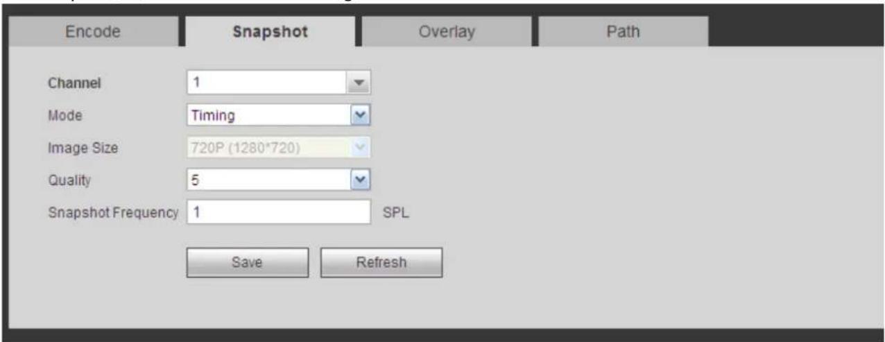
text_image
Encode Snapshot Overlay Path Channel 1 Mode Timing Image Size 720P (1280*720) Quality 5 Snapshot Frequency 1 SPL Save RefreshFigure 5-22
Please refer to the following sheet for detailed information.
| Parameter | Function |
| Snapshot type | There are two modes: Regular (schedule) and Trigger.● Regular snapshot is valid during the specified period you set.● Trigger snapshot only is valid when motion detect alarm, tampering alarm or local activation alarm occurs. |
| Image size | It is the same with the resolution of the main stream. |
| Quality | It is to set the image quality. There are six levels. |
| Interval | It is to set snapshot frequency. The value ranges from 1s to 7s. Or you can set customized value. The max setup is 3600s/picture. |
| Copy | Click it; you can copy current channel setup to other channel(s). |
5.8.1.3.3 Video Overlay
The video overlay interface is shown as in Figure 5-23.
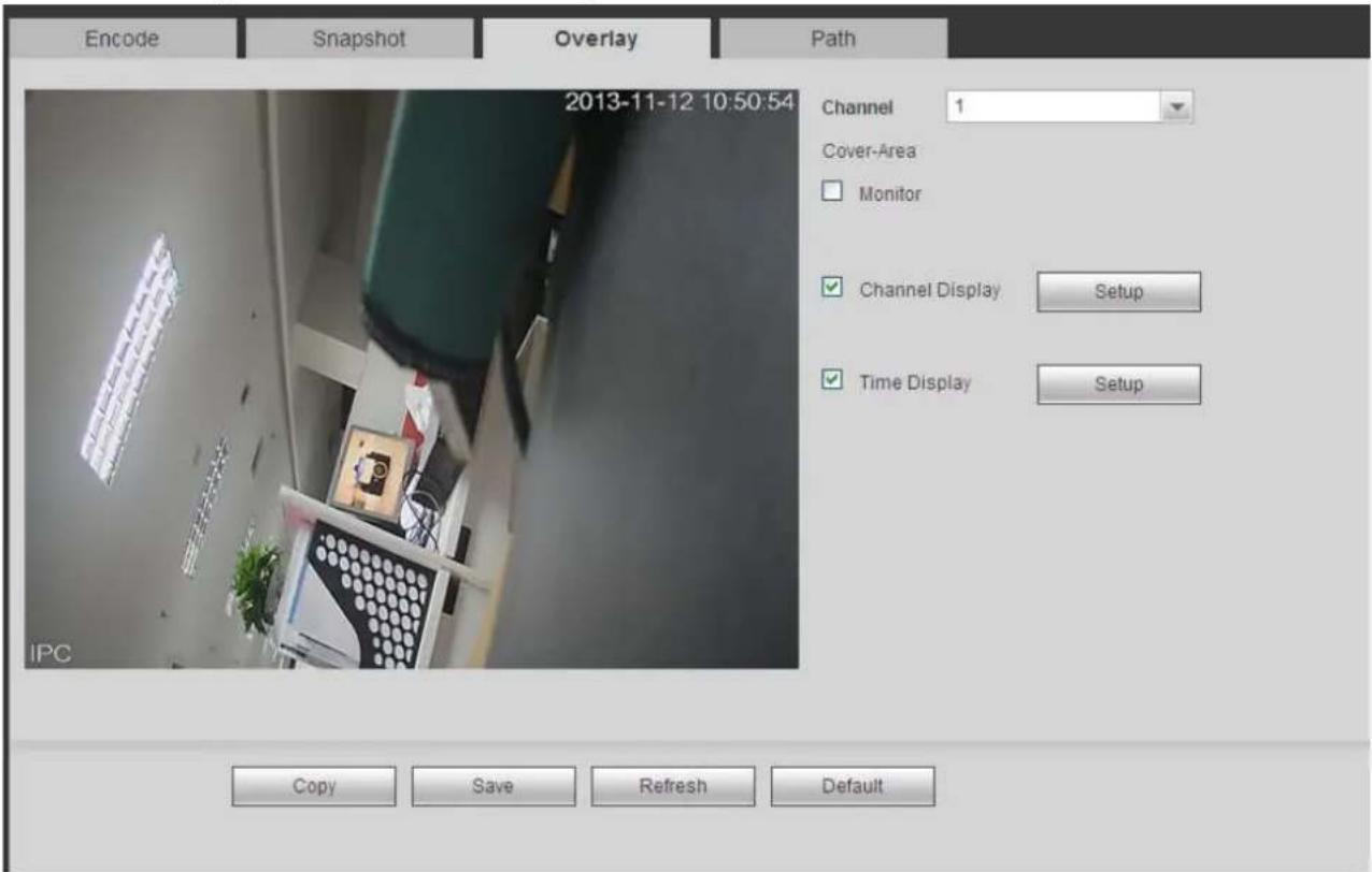
text_image
Encode Snapshot Overlay Path 2013-11-12 10:50:54 Channel 1 Cover-Area Monitor ✓ Channel Display Setup ✓ Time Display Setup IPC Copy Save Refresh DefaultFigure 5-23
Please refer to the following sheet for detailed information.
| Parameter | Function |
| Cover-area | Check Preview or Monitor first.Click Set button, you can privacy mask the specified video in the preview or monitor video.System max supports 4 privacy mask zones. |
| Time Title | You can enable this function so that system overlays time information in video window.You can use the mouse to drag the time title position.You can view time title on the live video of the WEB or the playback video. |
| Channel Title | You can enable this function so that system overlays channel information in video window.You can use the mouse to drag the channel title position.You can view channel title on the live video of the WEB or the playback video. |
5.8.1.3.4 Path
The storage path interface is shown as in Figure 5-24.
Here you can set snap image saved path (in the preview interface) and the record storage path

(in the preview interface).The default setup is C:\PictureDownload and C:\RecordDownload.
Please click the Save button to save current setup.
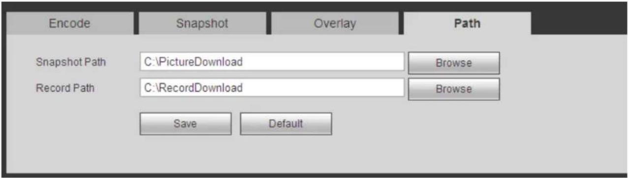
text_image
Encode Snapshot Overlay Path Snapshot Path C:\PictureDownload Browse Record Path C:\RecordDownload Browse Save DefaultFigure 5-24
5.8.1.4 Channel Name
Here you can set channel name. See Figure 5-25.
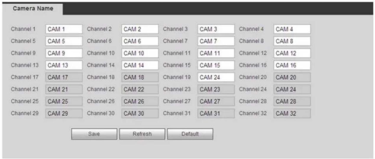
text_image
Camera Name Channel 1 CAM 1 Channel 2 CAM 2 Channel 3 CAM 3 Channel 4 CAM 4 Channel 5 CAM 5 Channel 6 CAM 6 Channel 7 CAM 7 Channel 8 CAM 8 Channel 9 CAM 9 Channel 10 CAM 10 Channel 11 CAM 11 Channel 12 CAM 12 Channel 13 CAM 13 Channel 14 CAM 14 Channel 15 CAM 15 Channel 16 CAM 16 Channel 17 CAM 17 Channel 18 CAM 18 Channel 19 CAM 24 Channel 20 CAM 20 Channel 21 CAM 21 Channel 22 CAM 22 Channel 23 CAM 23 Channel 24 CAM 24 Channel 25 CAM 25 Channel 26 CAM 26 Channel 27 CAM 27 Channel 28 CAM 28 Channel 29 CAM 29 Channel 30 CAM 30 Channel 31 CAM 31 Channel 32 CAM 32 Save Refresh DefaultFigure 5-25
5.8.1.5 IPC Upgrade
This interface is to upgrade network camera. See Figure 5-26.
Click Browse button to select upgrade file. Or you can use filter to select several network cameras at the same time.
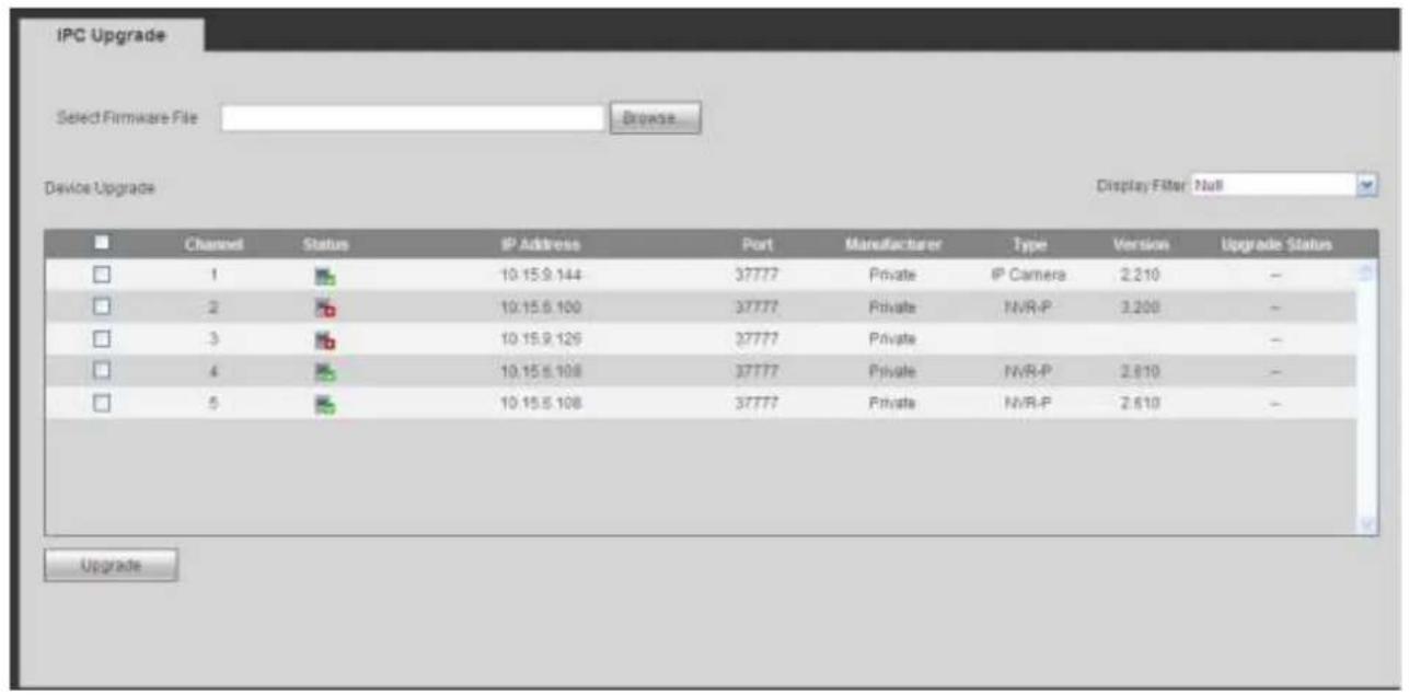
text_image
IPC Upgrade Select Firmware File Browse... Device Upgrade Display Filter Null Channel Status IP Address Port Manufacturer Type Version Upgrade Status 1 10.15.9.144 37777 Private IP Camera 2.210 - 2 10.15.6.100 37777 Private NVR-P 3.200 - 3 10.15.9.126 37777 Private - - 4 10.15.6.108 37777 Private NVR-P 2.610 - 5 10.15.6.108 37777 Private NVR-P 2.610 - UpgradeFigure 5-26
5.8.2 Network
5.8.2.1 TCP/IP
The TCP/IP interface is shown as in Figure 5-27.
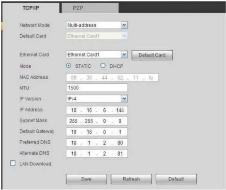
text_image
TCP/IP P2P Network Mode Multi-address Default Card Ethernet Card Ethernet Card1 Default Card Mode STATIC DHCP MAC Address 88 . 38 . 44 . 62 . 11 . fe MTU 1500 IP Version IPv4 IP Address 10 . 15 . 6 . 144 Subnet Mask 255 . 255 . 0 . 0 Default Gateway 10 . 15 . 0 . 1 Preferred DNS 10 . 1 . 2 . 80 Alternate DNS 10 . 1 . 2 . 81 LAN Download Save Refresh DefaultFigure 5-27
Please refer to the following sheet for detailed information.
| Parameter | Function |
| Mode | There are two modes: static mode and the DHCP mode.The IP/submask/gateway are null when you select the DHCP mode to auto search the IP.If you select the static mode, you need to set theIP/submask/gateway manually.● If you select the DHCP mode, you can view the IP/submask/gateway from the DHCP.● If you switch from the DHCP mode to the static mode, you need to reset the IP parameters.● Besides, IP/submask/gateway and DHCP are read-only when the PPPoE dial is OK. |
| Mac Address | It is to display host Mac address. |
| IP Version | It is to select IP version. IPV4 or IPV6.You can access the IP address of these two versions. |
| IP Address | Please use the keyboard to input the corresponding number to modify the IP address and then set the corresponding subnet mask and the default gateway. |
| Preferred DNS | DNS IP address. |
| Alternate DNS | Alternate DNS IP address. |
| For the IP address of IPv6 version, default gateway, preferred DNS and alternate DNS, the input value shall be 128-digit. It shall not be left in blank. | |
| LAN load | System can process the downloaded data first if you enable this function. The download speed is 1.5X or 2.0X of the normal speed. |
5.8.2.2 Connection
The connection interface is shown as in Figure 5-28.
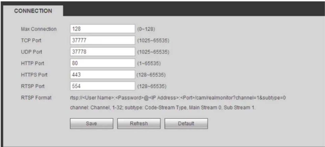
text_image
CONNECTION Max Connection 128 (0~128) TCP Port 37777 (1025~65535) UDP Port 37778 (1025~65535) HTTP Port 80 (1~65535) HTTPS Port 443 (128~65535) RTSP Port 554 (128~65535) RTSP Format rtsp://User Name>:Password>@Figure 5-28
Please refer to the following sheet for detailed information.
| Parameter | Function |
| Max connection | It is the max Web connection for the same device. The value ranges from 1 to 120. The default setup is 120. |
| TCP port | The default value is 37777. You can input the actual portnumber if necessary. |
| UDP port | The default value is 37778. You can input the actual port number if necessary. |
| HTTP port | The default value is 80. You can input the actual port number if necessary. |
| HTTPS | The default value is 443. You can input the actual port number if necessary. |
| RTSP port | The default value is 554. |
5.8.2.3 WIFI AP
Please note this function is for some series only.
The WIFI AP interface is shown as in Figure 5-29. Here you can set WIFI hotspot, so that the network camera can use the hotspot to connect to the network.
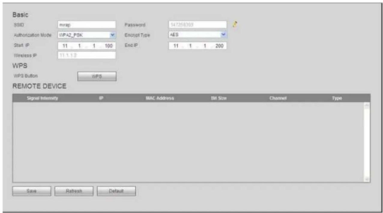
text_image
Basic SSID mmap Password 147258363 Authorization Mode WPA2_PSK Encrypt Type AES Start IP 11 1 1 100 End IP 11 1 1 200 Wireless IP 11.1.1.2 WPS WPS Button WPS REMOTE DEVICE Signal Intensity IP MAC Address Bit Size Channel Type Save Refresh DefaultFigure 5-29
Please refer to the following sheet for detailed information.
| Parameter | Function |
| SSID | It is to set SSID name. You can use this name to search the device. |
| Password | It is to set SSID password. You can use this password to connect to the network. |
| Authorization | Select authentication from the dropdown list. |
| Encrypt type | Select encryption type from the dropdown list. |
| Start IP/End IP | Input start IP and end IP. The NVR can allocate the IP address in the range you specified here. |
| WPS | Click WPS button to enable WPS function. After the network camera enabled this function, it can automatically connect to the network. |
| Remote device | In the list, you can view the network camera(s) that connected to the NVR. It includes signal intensity, IP, MAC address, bit rate, channel number, type, status and etc. |
5.8.2.4 WIFI
Please note this function is for the device of WIFI module.
The WIFI interface is shown as in Figure 5-30.
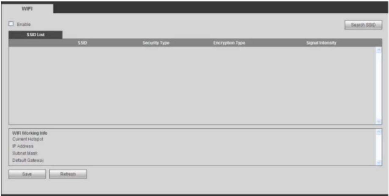
text_image
WIFI Enable SSID List SSID Security Type Encryption Type Signal Intensity WIFI Working Info Current Hotspot IP Address Subnet Mask Default Gateway Save RefreshFigure 5-30
Please check the box to enable WIFI function and then click the Search SSID button. Now you can view all the wireless network information in the following list. Double click a name to connect to it. Click Refresh button, you can view latest connection status.
5.8.2.5 3G
5.8.2.5.1 CDMA/GPRS
The CDMA/GPRS interface is shown as in Figure 5-31.

text_image
CDMA/GPRS Mobile WLAN Type No Service APN AUTH PAP Dial No. User Name Password Pulse Interval Enable Dial/SMS Activate Second WLAN Status IP Address Wireless Signal Search Save Refresh DefaultFigure 5-31
Please refer to the following sheet for detailed information.
| Parameter | Function |
| WLAN type | Here you can select 3G network type to distinguish the 3G module from different ISP. The types include WCDMA, CDMA1x and etc. |
| APN/Dial No. | Here is the important parameter of PPP. |
| Authorization | It includes PAP,CHAP,NO_AUTH. |
| Pulse interval | It is to set time to end 3G connection after you close extra stream monitor. For example, if you input 60 here, system ends 3G connection after you close extra stream monitor 60 seconds. |
| ImportantIf the pulse interval is 0, then system does not end 3G connection after you close the extra stream monitor.Pulse interval here is for extra stream only. This item is null if you are using main stream to monitor. | |
5.8.2.5.2 Mobile
The mobile setup interface is shown as in Figure 5-32.
Here you can activate (send out "on") or turn off (Send out "off") the 3G connected phone or mobile phone, or the phone you set to get alarm message.
Check send SMS box and then input the phone number in the receiver column. Click to add one
receiver. Repeat the above steps you can add more phones. Select a phone number and then click you can delete it. Click OK button to complete the setup.


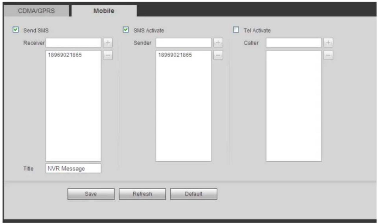
text_image
CDMA/GPRS Mobile Send SMS Receiver 18969021865 SMS Activate Sender 18969021865 Tel Activate Caller Title NVR Message Save Refresh DefaultFigure 5-32
5.8.2.6 PPPoE
The PPPoE interface is shown as in Figure 5-33.
Input the PPPoE user name and password you get from the IPS (internet service provider) and enable PPPoE function. Please save current setup and then reboot the device to get the setup activated.
Device connects to the internet via PPPoE after reboot. You can get the IP address in the WAN from the IP address column.
Please note, you need to use previous IP address in the LAN to login the device. Please go to the IP address item to via the device current device information. You can access the client-end via this new address.
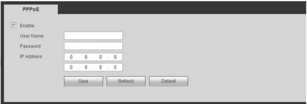
text_image
PPPoE Enable User Name Password IP Address 0 . 0 . 0 . 0 0 . 0 . 0 . 0 Save Refresh DefaultFigure 5-33
5.8.2.7 DDNS
The DDNS interface is shown as in Figure 5-34.
The DDNS is to set to connect the various servers so that you can access the system via the server.
Please go to the corresponding service website to apply a domain name and then access the system via the domain. It works even your IP address has changed.
Please select DDNS from the dropdown list (Multiple choices). Before you use this function, please make sure your purchased device support current function.
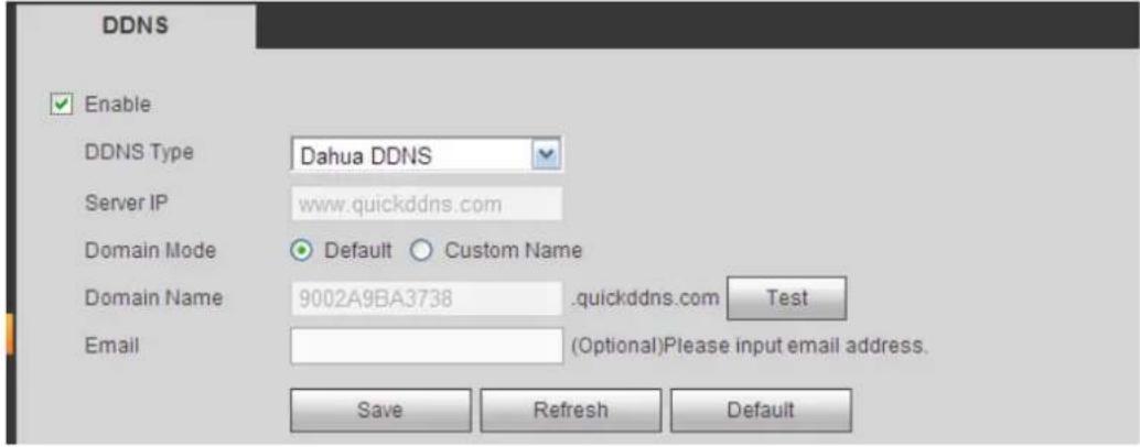
text_image
DDNS Enable DDNS Type Dahua DDNS Server IP www.quickddns.com Domain Mode Default Custom Name Domain Name 9002A9BA3738 .quickddns.com Test Email (Optional)Please input email address. Save Refresh DefaultFigure 5-34
Please refer to the following sheet for detailed information.
| Parameter | Function |
| Server Type | You can select DDNS protocol from the dropdown list and then enable DDNS function. |
| Server IP | DDNS server IP address |
| Server Port | DDNS server port. |
| Domain Name | Your self-defined domain name. |
| User | The user name you input to log in the server. |
| Password | The password you input to log in the server. |
| Update period | Device sends out alive signal to the server regularly.You can set interval value between the device and DDNS server here. |
Dahua DDNS and Client-end Introduction
1) Background Introduction
Device IP is not fixed if you use ADSL to login the network. The DDNS function allows you to access the NVR via the registered domain name. Besides the general DDNS, the Dahua DDNS works with the device from the manufacturer so that it can add the extension function.
2) Function Introduction
The Dahua DDNS client has the same function as other DDNS client end. It realizes the bonding of the domain name and the IP address. Right now, current DDNS server is for our own devices only. You need to refresh the bonding relationship of the domain and the IP regularly. There is no user name, password or the ID registration on the server. At the same time, each device has a default domain name (Generated by MAC address) for your option. You can also use customized valid domain name (has not registered.).
3) Operation
Before you use Dahua DDNS, you need to enable this service and set proper server address, port value and domain name.
- Server address: www.dahuaddns.com
- Port number: 80
- Domain name: There are two modes: Default domain name and customized domain name.
Except default domain name registration, you can also use customized domain name (You can input your self-defined domain name.) After successful registration, you can use domain name to login installed of the device IP.
- User name: It is optional. You can input your commonly used email address.
Important
- Do not register frequently. The interval between two registrations shall be more than 60 seconds. Too many registration requests may result in server attack.
- System may take back the domain name that is idle for one year. You can get a notification email before the cancel operation if your email address setup is OK.
5.8.2.8 IP filter
The IP filter interface is shown as in Figure 5-35.
After you enabled trusted sites function, only the IP listed below can access current NVR.
If you enable blocked sites function, the following listed IP addresses can not access current NVR.
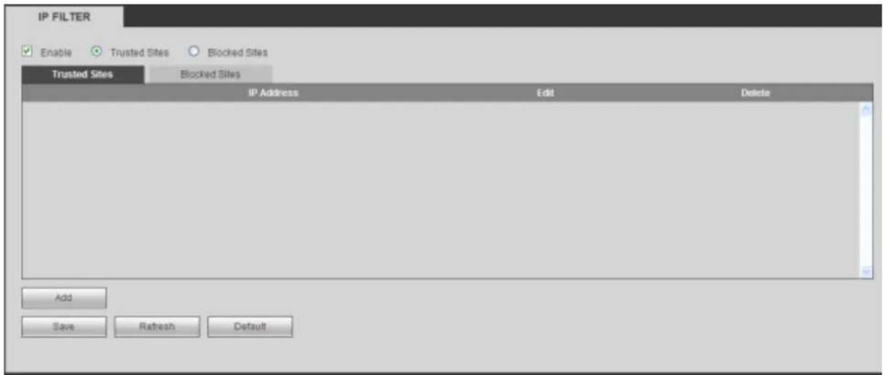
text_image
IP FILTER Enable Trusted Sites Blocked Sites Trusted Sites Blocked Sites IP Address Edit Delete Add Save Refresh DefaultFigure 5-35
5.8.2.9 Email
The email interface is shown as in Figure 5-36.
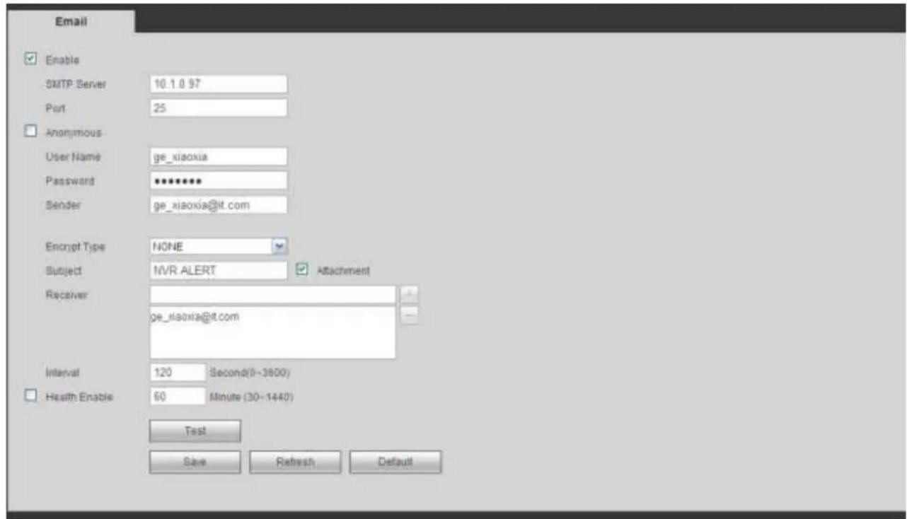
text_image
Email Enable SMTP Server 10.1.9.97 Port 25 Anonymous User Name ge_xiaoxia Password ********** Sender ge_xiaoxia@it.com Encrypt Type NONE Subject MVR ALERT Attachment Receiver ge_xiaoxia@it.com Interval 120 Second(0-3800) Health Enable 60 Minute (30-1440) Test Save Refresh DefaultFigure 5-36
Please refer to the following sheet for detailed information.
| Parameter | Function |
| Enable | Please check the box here to enable email function. |
| SMTP Server | Input server address and then enable this function. |
| Port | Default value is 25. You can modify it if necessary. |
| Anonymity | For the server supports the anonymity function. You can auto login anonymously. You do not need to input the user name. password and the sender information. |
| User Name | The user name of the sender email account. |
| Password | The password of sender email account. |
| Sender | Sender email address. |
| Authentication (Encryption mode) | You can select SSL or none. |
| Subject | Input email subject here. |
| Attachment | System can send out the email of the snapshot picture once you check the box here. |
| Receiver | Input receiver email address here. Max three addresses. It supports SSL, TLS email box. |
| Interval | The send interval ranges from 0 to 3600 seconds. 0 means there is no interval.Please note system will not send out the email immediately when the alarm occurs. When the alarm, motion detection or the abnormality event activates the email, system sends out the email according to the interval you specified here. Thisfunction is very useful when there are too many emails activated by the abnormality events, which may result in heavy load for the email server. |
| Health mail enable | Please check the box here to enable this function. |
| Update period (interval) | This function allows the system to send out the test email to check the connection is OK or not.Please check the box to enable this function and then set the corresponding interval. The value ranges from 30 minutes to 1440 minutes.System can send out the email regularly as you set here. |
| Email test | The system will automatically sent out a email once to test the connection is OK or not .Before the email test, please save the email setup information. |
5.8.2.10 UPnP
It allows you to establish the mapping relationship between the LAN and the public network. Here you can also add, modify or remove UPnP item. See Figure 5-37.
- In the Windows OS, From Start->Control Panel->Add or remove programs. Click the "Add/Remove Windows Components" and then select the "Network Services" from the Windows Components Wizard.
- Click the Details button and then check the "Internet Gateway Device Discovery and Control client" and "UPnP User Interface". Please click OK to begin installation.
- Enable UPnP from the Web. If your UPnP is enabled in the Windows OS, the NVR can auto detect it via the "My Network Places"
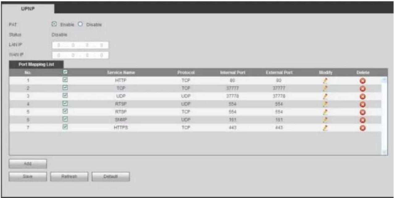
text_image
UPNP PAT Enable Disable Status Disable LAN IP 0 0 0 0 WAN IP 0 0 0 0 Port Mapping List No Service Name Protocol Internal Port External Port Modify Delete 1 HTTP TCP 80 80 2 TCP TCP 37777 27777 3 UDP UDP 37778 37778 4 RTSP UDP 554 554 5 RTSP TCP 554 554 6 SMTP UDP 161 161 7 HTTPS TCP 443 443 Add Save Refresh DefaultFigure 5-37
Please refer to the following sheet for detailed information.
| Parameter | Function |
| PAT | Check the corresponding box to enable PAT function. |
| Status | Display UPnP function status. |
| Port mapping list | It is corresponding to the UPnP mapping information on the router.Check the box before the service name to enable current PAT service.Otherwise, the service is null.·Service name: Customized name.·Protocol: Protocol type.·Internal port: The port mapped to the port.·External port: The port current device needs to map.·Device has three mapping items: HTTP/TCP/UDP.NoteWhen you set the external port (outport) of the router, the value ranges from 1024 to 5000. Do not use port 1~255 or system port 256~1023, in case there is conflict. |
| Add | Click Add button to add map relationship.NoteFor the data transmission protocol TCP/UDP, the external port and the internal port shall be the same to guarantee proper data transmission. |
| Delete | Select one service and then click to delete map relationship. |
5.8.2.11 SNMP
The SNMP interface is shown as in Figure 5-38.
The SNMP allows the communication between the network management work station software and the proxy of the managed device. It is reserved for the 3^rd party to develop.
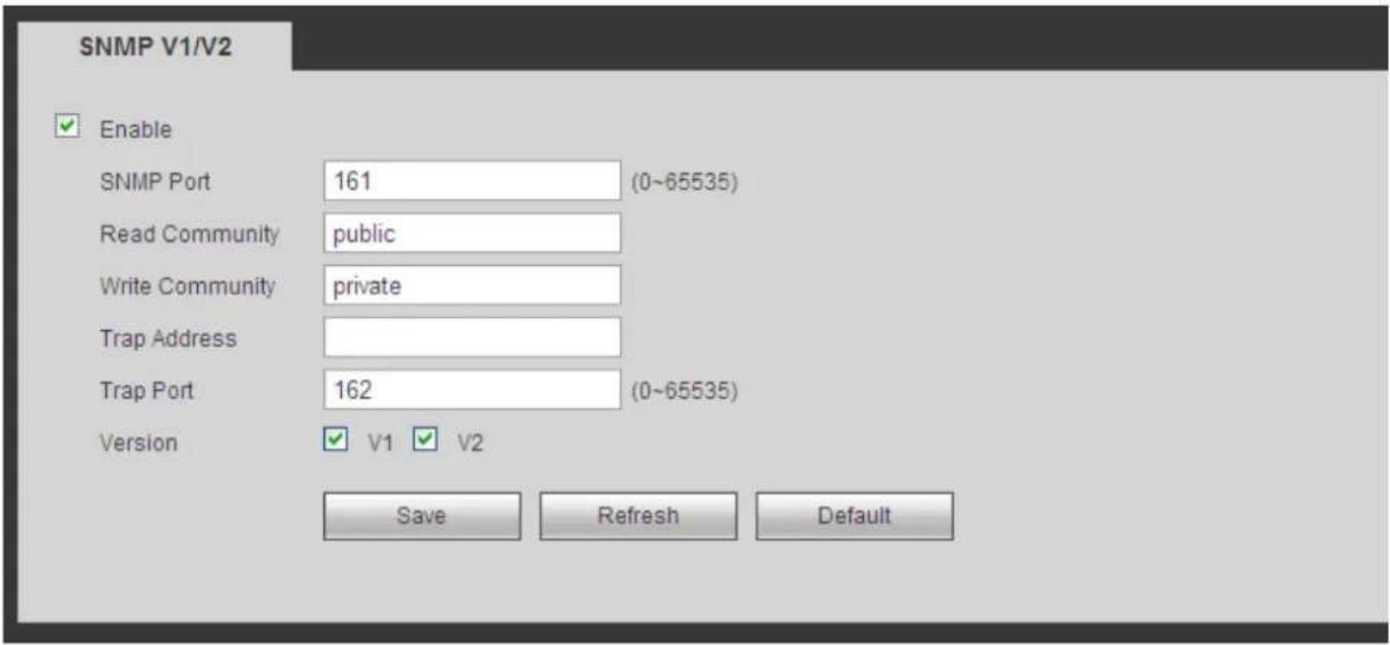
text_image
SNMP V1/V2 Enable SNMP Port 161 (0~65535) Read Community public Write Community private Trap Address Trap Port 162 (0~65535) Version V1 V2 Save Refresh DefaultFigure 5-38
Please refer to the following sheet for detailed information.
| Parameter | Function |
| SNMP Port | The listening port of the proxy program of the device. It is a UDP port not a TCP port. The value ranges from 1 to 65535.The default value is 161 |
| Read Community | It is a string. It is a command between the manage process and the proxy process. It defined the authentication, access control and the management relationship between one proxy and one group of the managers. Please make sure the device and the proxy are the same.The read community will read all the objects the SNMP supported in the specified name. The default setup is public. |
| Write Community | It is a string. It is a command between the manage process and the proxy process. It defined the authentication, access control and the management relationship between one proxy and one group of the managers. Please make sure the device and the proxy are the same.The read community will read/write/access all the objects the SNMP supported in the specified name. The default setup is write. |
| Trap address | The destination address of the Trap information from the proxy program of the device. |
| Trap port | The destination port of the Trap information from the proxy program of the device. It is for the gateway device and the client-end PC in the LAN to exchange the information. It is a non-protocol connection port. It has no effect on the network applications. It is a UDP port not TCP port. The value ranges from 1 to 165535. The default value is 162. |
| SNMP version | ● Check V1, system only processes the information of V1.● Check V2, system only processes the information of V2. |
5.8.2.12 Multicast
The multicast interface is shown as in Figure 5-39.
Multicast is a transmission mode of data packet. When there is multiple-host to receive the same data packet, multiple-cast is the best option to reduce the broad width and the CPU load. The source host can just send out one data to transit. This function also depends on the relationship of the group member and group of the outer.
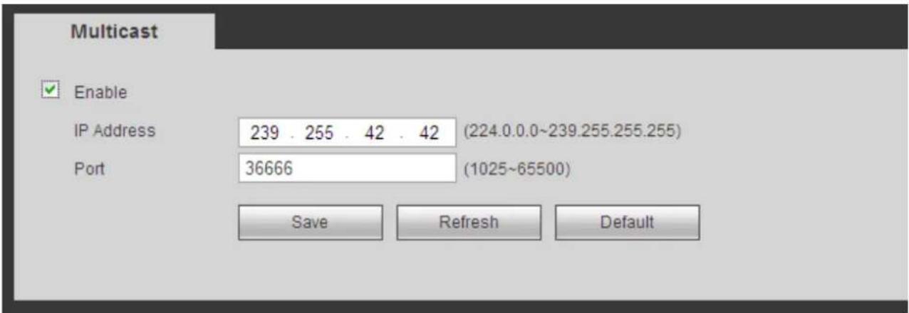
text_image
Multicast Enable IP Address 239 . 255 . 42 . 42 (224.0.0.0~239.255.255.255) Port 36666 (1025~65500) Save Refresh DefaultFigure 5-39
5.8.2.13 Auto Register
The auto register interface is shown as below. See Figure 5-40.
This function allows the device to auto register to the proxy you specified. In this way, you can use the
client-end to access the NVR and etc via the proxy. Here the proxy has a switch function. In the network service, device supports the server address of IPv4 or domain.
Please follow the steps listed below to use this function.
Please set proxy server address, port, and sub-device name at the device-end. Please enable the auto register function, the device can auto register to the proxy server.
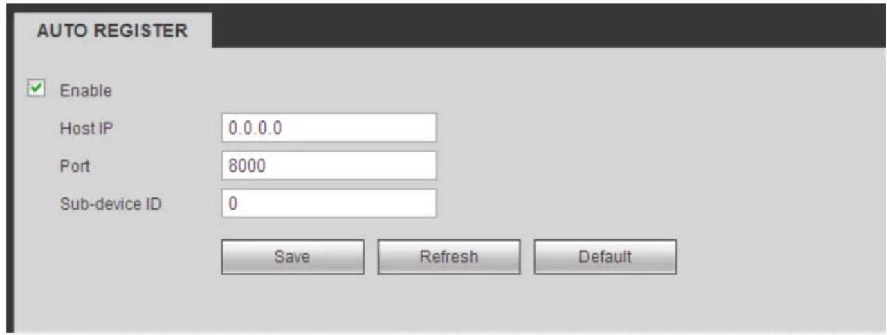
text_image
AUTO REGISTER Enable Host IP 0.0.0.0 Port 8000 Sub-device ID 0 Save Refresh DefaultFigure 5-40
5.8.2.14 Alarm Centre
The alarm center interface is shown as below. See Figure 5-41.
This interface is reserved for you to develop. System can upload alarm signal to the alarm center when local alarm occurs.
Before you use alarm center, please set server IP, port and etc. When an alarm occurs, system can send out data as the protocol defined, so the client-end can get the data.
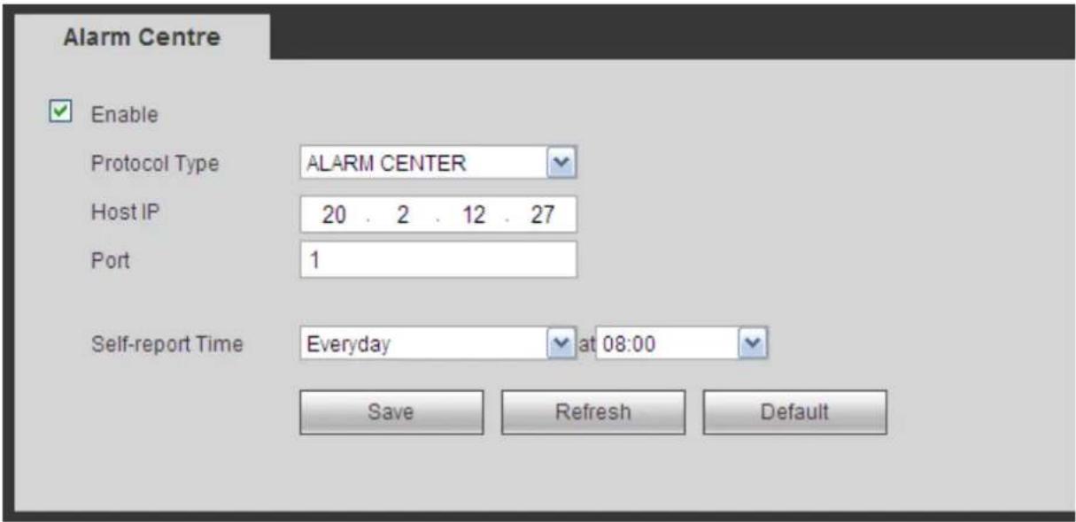
text_image
Alarm Centre Enable Protocol Type ALARM CENTER Host IP 20 . 2 . 12 . 27 Port 1 Self-report Time Everyday at 08:00 Save Refresh DefaultFigure 5-41
5.8.2.15 HTTPS
In this interface, you can set to make sure the PC can successfully login via the HTTPS. It is to guarantee communication data security. The reliable and stable technology can secure the user information security
and device safety. See Figure 5-42.
Note
- You need to implement server certificate again if you have changed device IP.
- You need to download root certificate if it is your first time to use HTTPS on current PC.
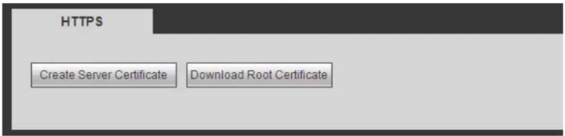
text_image
HTTPS Create Server Certificate Download Root CertificateFigure 5-42
5.8.2.15.1 Create Server Certificate
If it is your first time to use this function, please follow the steps listed below.
In Figure 5-42, click button, input country name, state name and etc. Click Create button. See Figure 5-43.
Note
Please make sure the IP or domain information is the same as your device IP or domain name.
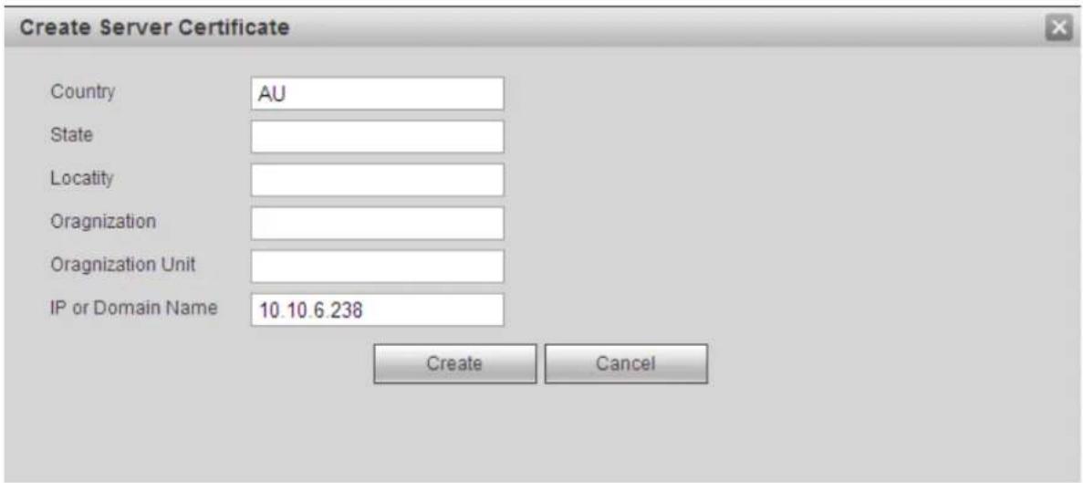
text_image
Create Server Certificate Country AU State Locality Oragnization Oragnization Unit IP or Domain Name 10.10.6.238 Create CancelFigure 5-43
You can see the corresponding prompt. See Figure 5-44. Now the server certificate is successfully created.

text_image
HTTPS Create Server Certificate Download Root Certificate ✓ Create SucceedFigure 5-44
5.8.2.15.2 Download root certificate
In Figure 5-42, click button, system pops up a dialogue box. See Figure 5-45.
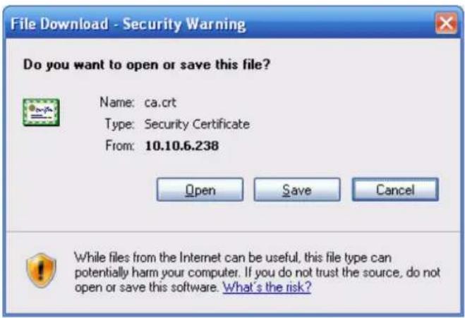
text_image
File Download - Security Warning Do you want to open or save this file? Name: ca.crt Type: Security Certificate From: 10.10.6.238 Open Save Cancel While files from the Internet can be useful, this file type can potentially harm your computer. If you do not trust the source, do not open or save this software. What's the risk?Figure 5-45
Click Open button, you can go to the following interface. See Figure 5-46.
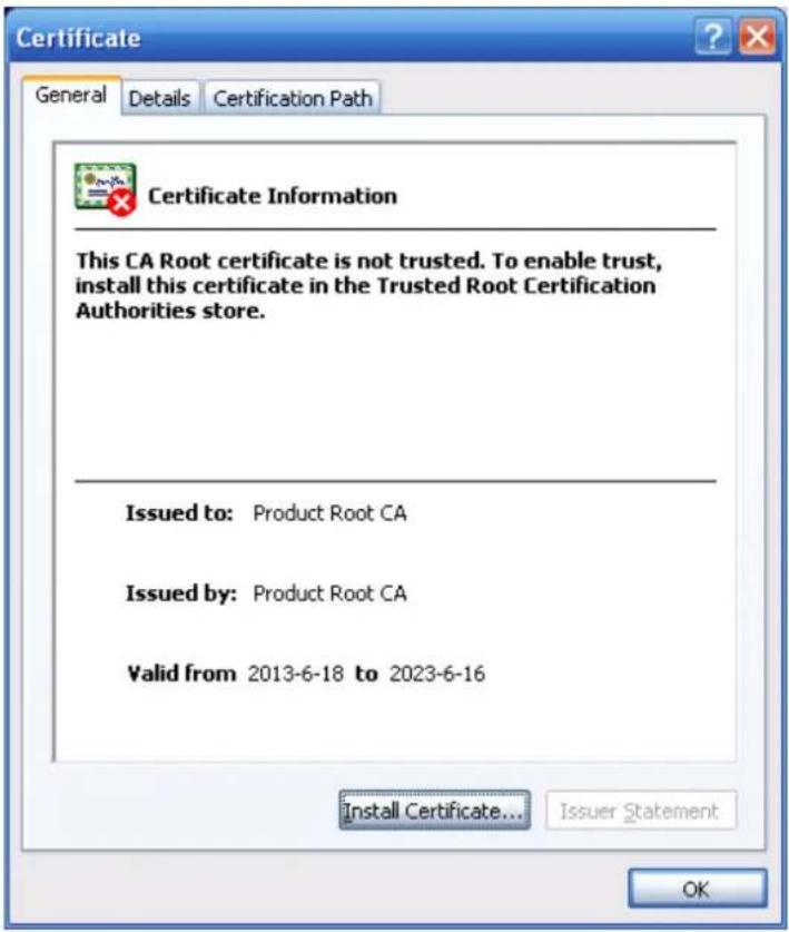
text_image
Certificate General Details Certification Path Certificate Information This CA Root certificate is not trusted. To enable trust, install this certificate in the Trusted Root Certification Authorities store. Issued to: Product Root CA Issued by: Product Root CA Valid from 2013-6-18 to 2023-6-16 Install Certificate... Issuer Statement OKFigure 5-46
Click Install certificate button, you can go to certificate wizard. See Figure 5-47.
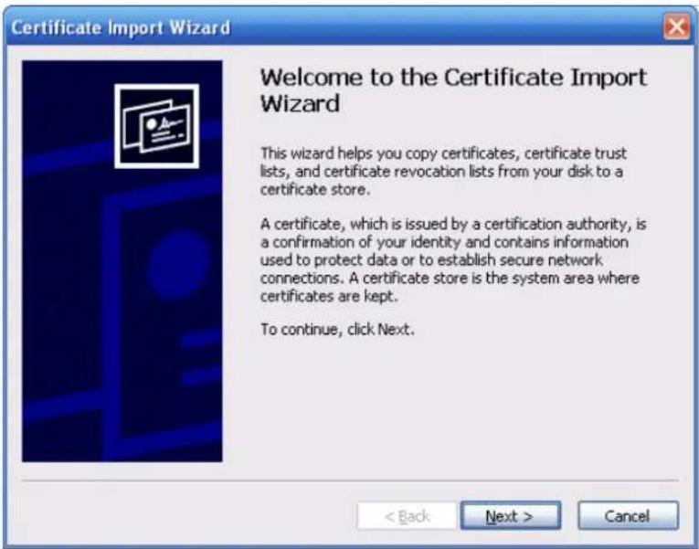
text_image
Certificate Import Wizard Welcome to the Certificate Import Wizard This wizard helps you copy certificates, certificate trust lists, and certificate revocation lists from your disk to a certificate store. A certificate, which is issued by a certification authority, is a confirmation of your identity and contains information used to protect data or to establish secure network connections. A certificate store is the system area where certificates are kept. To continue, click Next.Figure 5-47
Click Next button to continue. Now you can select a location for the certificate. See Figure 5-48.
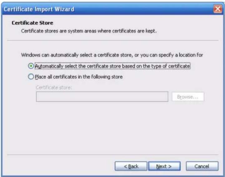
text_image
Certificate Import Wizard Certificate Store Certificate stores are system areas where certificates are kept. Windows can automatically select a certificate store, or you can specify a location for Automatically select the certificate store based on the type of certificate Place all certificates in the following store Certificate store: Browse... < Back Next > CancelFigure 5-48
Click Next button, you can see the certificate import process is complete. See Figure 5-49.
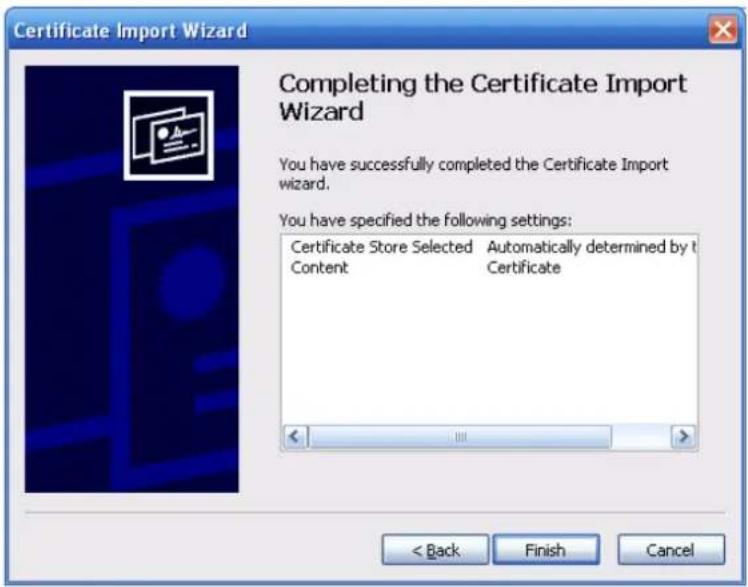
text_image
Certificate Import Wizard Completing the Certificate Import Wizard You have successfully completed the Certificate Import wizard. You have specified the following settings: Certificate Store Selected Automatically determined by t Content Certificate < Back Finish CancelFigure 5-49
Click Finish button, you can see system pops up a security warning dialogue box. See Figure 5-50.
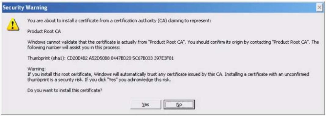
text_image
Security Warning You are about to install a certificate from a certification authority (CA) claiming to represent: Product Root CA Windows cannot validate that the certificate is actually from "Product Root CA". You should confirm its origin by contacting "Product Root CA". The following number will assist you in this process: Thumbprint (sha1): CD20E4B2 A52D50B8 8447BD20 5C67B033 397E3F81 Warning: If you install this root certificate, Windows will automatically trust any certificate issued by this CA. Installing a certificate with an unconfirmed thumbprint is a security risk. If you click "Yes" you acknowledge this risk. Do you want to install this certificate? Yes NoFigure 5-50
Click Yes button, system pops up the following dialogue box, you can see the certificate download is complete. See Figure 5-51.
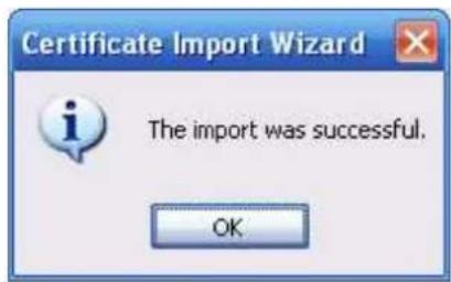
text_image
Certificate Import Wizard The import was successful. OKFigure 5-51
5.8.2.15.3 View and set HTTPS port
From Setup->Network->Connection, you can see the following interface. See Figure 5-52. You can see HTTPS default value is 443.

text_image
CONNECTION Max Connection 128 (0~128) TCP Port 37777 (1025~65535) UDP Port 37778 (1025~65535) HTTP Port 80 (1~65535) HTTPS Port 443 (128~65535) RTSP Port 554 (128~65535) RTSP Format rtsp://User Name>:Password>@Figure 5-52
5.8.2.15.4 Login
Open the browser and then input https://xx.xx.xx.xx:port.
xx.xx.xx.xx: is your device IP or domain mane.
Port is your HTTPS port. If you are using default HTTPS value 443, you do not need to add port information here. You can input https://xx.xx.xx.xx to access.
Now you can see the login interface if your setup is right.
5.8.2.16 P2P
You can use your cell phone to scan the QR code and add it to the cell phone client.
Via the SN from scanning the QR code, you can access the device in the WAN. Please refer to the P2P operation manual included in the resources CD.
The P2P interface is shown as in Figure 5-53.
Check the Enable box to enable P2P function and then click the Save button. Now you can view the device status and SN.
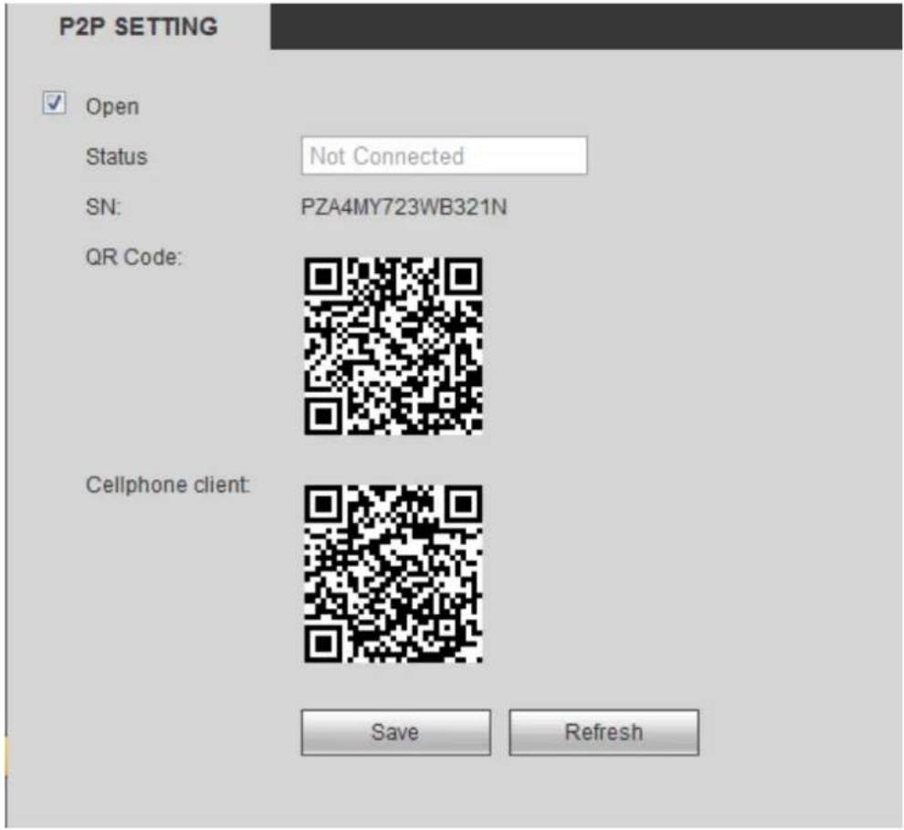
text_image
P2P SETTING ✓ Open Status Not Connected SN: PZA4MY723WB321N QR Code: Cellphone client: Save RefreshFigure 5-53
5.8.3 Event
5.8.3.1 Video detect
5.8.3.1.1 Motion Detect
After analysis video, system can generate a video loss alarm when the detected moving signal reached the sensitivity you set here.
The motion detect interface is shown as in Figure 5-54.
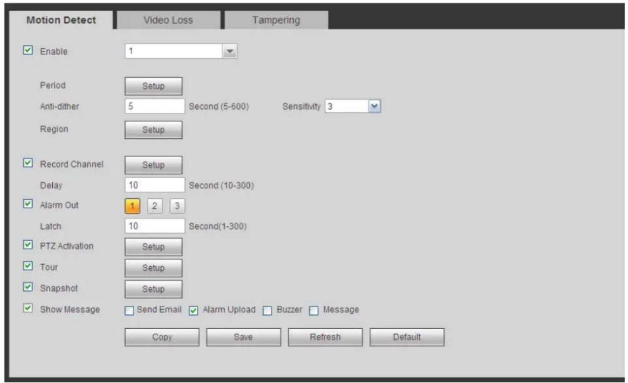
text_image
Motion Detect Video Loss Tampering Enable 1 Period Setup Anti-dither 5 Second (5-600) Sensitivity 3 Region Setup Record Channel Setup Delay 10 Second (10-300) Alarm Out 1 2 3 Latch 10 Second(1-300) PTZ Activation Setup Tour Setup Snapshot Setup Show Message Send Email Alarm Upload Buzzer Message Copy Save Refresh DefaultFigure 5-54
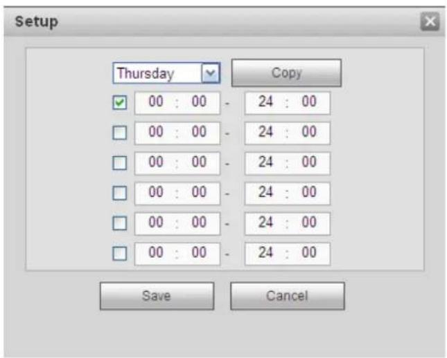
text_image
Setup Thursday Copy 00 : 00 - 24 : 00 00 : 00 - 24 : 00 00 : 00 - 24 : 00 00 : 00 - 24 : 00 00 : 00 - 24 : 00 00 : 00 - 24 : 00 00 : 00 - 24 : 00 Save CancelFigure 5-55
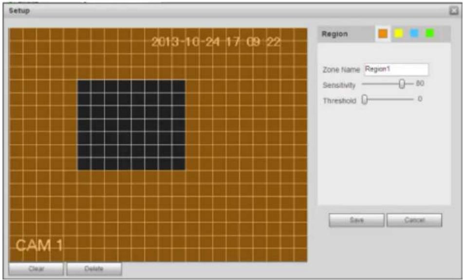
text_image
Setup 2013-10-24 17:09:22 Region Zone Name Region1 Sensitivity 80 Threshold 0 CAM 1 Clear Delete Says CancelFigure 5-56
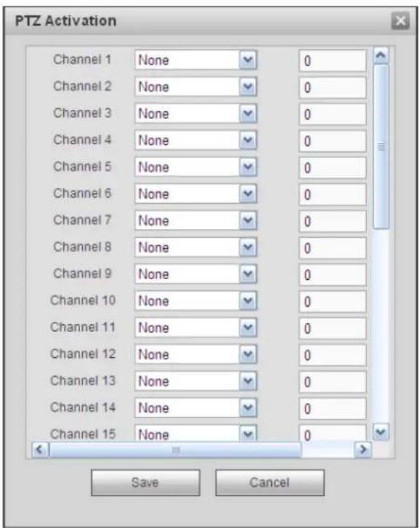
text_image
PTZ Activation Channel 1 None 0 Channel 2 None 0 Channel 3 None 0 Channel 4 None 0 Channel 5 None 0 Channel 6 None 0 Channel 7 None 0 Channel 8 None 0 Channel 9 None 0 Channel 10 None 0 Channel 11 None 0 Channel 12 None 0 Channel 13 None 0 Channel 14 None 0 Channel 15 None 0 Save CancelFigure 5-57
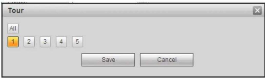
text_image
Tour All 1 2 3 4 5 Save CancelFigure 5-58
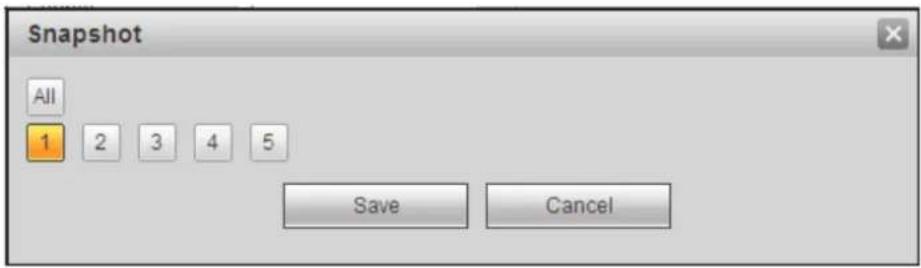
text_image
Snapshot All 1 2 3 4 5 Save CancelFigure 5-59
Please refer to the following sheet for detailed information.
| Parameter | Function |
| Enable | You need to check the box to enable motion detection function.Please select a channel from the dropdown list. |
| Period | Motion detection function becomes activated in the specified periods. See Figure 5-55.There are six periods in one day. Please draw a circle to enable corresponding period.Click OK button, system goes back to motion detection interface, please click save button to exit. |
| Anti-dither | System only memorizes one event during the anti-dither period.The value ranges from 5s to 600s. |
| Sensitivity | There are six levels. The sixth level has the highest sensitivity. |
| Region | If you select motion detection type, you can click this button to set motion detection zone. The interface is shown as in Figure 5-56.Here you can set motion detection zone. There are four zones for you to set. Please select a zone first and then left drag the mouse to select a zone. The corresponding color zone displays different detection zone. You can click Fn button to switch between the arm mode and disarm mode. In arm mode, you can click the direction buttons to move the green rectangle to set the motion detection zone. After you completed the setup, please click ENTER button to exit current setup. Do remember click save button to save current setup. If you click ESC button to exit the region setup interface system will not save your zone setup. |
| Record channel | System auto activates motion detection channel(s) to record once an alarm occurs. Please note you need to set motion detect record period and go to Storage-> Schedule to set current channel as schedule record. |
| Record Delay | System can delay the record for specified time after alarm ended.The value ranges from 10s to 300s. |
| Alarm out | Enable alarm activation function. You need to select alarm output port so that system can activate corresponding alarm device when an alarm occurs. |
| Latch | System can delay the alarm output for specified time after an alarm ended. The value ranges from 1s to 300s. |
| Show message | System can pop up a message to alarm you in the local host screen if you enabled this function. |
| Buzzer | Check the box here to enable this function. The buzzer beeps when an alarm occurs. |
| Alarm upload | System can upload the alarm signal to the centre (Including alarm centre. |
| Message | When 3G network connection is OK, system can send out a message when motion detect occurs. |
| Send Email | If you enabled this function, System can send out an email to alert you when an alarm occurs. |
| Tour | You need to click setup button to select tour channel. System begins 1-wiindow or multiple-window tour display among the channel(s) you set to record when an alarm occurs. See Figure 5-58. |
| PTZ Activation | Here you can set PTZ movement when alarm occurs. Such as go to preset X. See Figure 5-57. |
| Snapshot | Click setup button to select snapshot channel. See Figure 5-59. |
| Video Matrix | This function is for motion detect only. Check the box here to enable video matrix function. Right now system supports one-channel tour function. System takes “first come and first serve” principle to deal with the activated tour. System will process the new tour when a new alarm occurs after previous alarm ended. Otherwise it restores the previous output status before the alarm activation. |
5.8.3.1.2 Video Loss
The video loss interface is shown as in Figure 5-60.
Please note video loss does not support anti-dither, sensitivity, region setup. For rest setups, please refer to chapter 5.8.3.1.1 motion detect for detailed information.
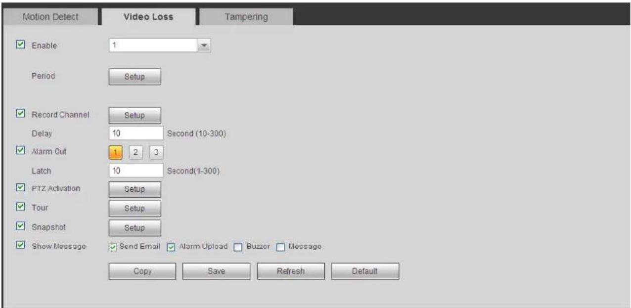
text_image
Motion Detect Video Loss Tampering Enable 1 Period Setup Record Channel Setup Delay 10 Second (10-300) Alarm Cut 1 2 3 Latch 10 Second(1-300) PTZ Activation Setup Tour Setup Snapshot Setup Show Message Send Email Alarm Upload Buzzer Message Copy Save Refresh DefaultFigure 5-60
5.8.3.1.3 Tampering
The tampering interface is shown as in Figure 5-61.
After analysis video, system can generate a tampering alarm when the detected moving signal reached the sensitivity you set here.
For detailed setups, please refer to chapter 5.8.3.1.1 motion detect for detailed information.

text_image
Motion Detect Video Loss Tampering Enable 1 Period Setup Record Channel Setup Delay 10 Second (10-300) Alarm Out 1 2 3 Latch 10 Second(1-300) PTZ Activation Setup Tour Setup Snapshot Setup Show Message Send Email Alarm Upload Buzzer Message Copy Save Refresh DefaultFigure 5-61
5.8.3.2 IVS (Optional)

Please make sure you are connecting to the smart network camera, otherwise you can not
use IVS function!
From main menu->Setup->Event->IVS, you can go to the IVS interface. It includes four interfaces: Tripwire/intrusion/object/scene.
5.8.3.2.1 Tripwire
Please make sure you are connecting to the smart network camera, otherwise you can not use IVS function!
From main menu->Setup->Event->IVS->Tripwire, you can see the following interface. See Figure 5-62.
System generates an alarm once there is any object crossing the tripwire in the specified direction.
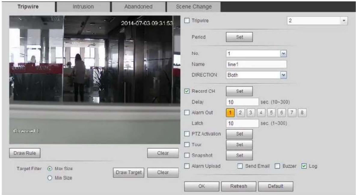
text_image
Tripwire Intrusion Abandoned Scene Change 2014-07-03 09:31:53 Tripwire 2 Period Set No. 1 Name line1 DIRECTION Both Record CH Set Delay 10 sec. (10~300) Alarm Out 1 2 3 4 5 6 7 8 Latch 10 sec. (1~300) PTZ Activation Set Tour Set Snapshot Set Alarm Upload Send Email Buzzer Log OK Refresh Default Channel 1 Draw Rule Clear Target Filter Max Size Min Size Draw Target ClearFigure 5-62
Check the Tripwire box to enable tripwire function.
Select SN (Line1/2/3/4) and direction, and then input customized rule name.
- No. and Line1/2/3/4: System supports four tripwires. Each SN stands for one tripwire.
- Direction: There are three options: A->B, B->A, both. System can generate an alarm once there is any object crossing in the specified direction.
Now you can draw a rule. Click Draw rule button and then left click mouse to draw a tripwire. The tripwire can be a direct line, curve or polygon. Right click mouse to complete. See Figure 5-63.
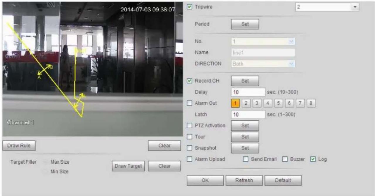
text_image
2014-07-03 09:38:07 Tripwire 2 Period Set No. 1 Name line1 DIRECTION Both Record CH Set Delay 10 sec. (10~300) Alarm Out 1 2 3 4 5 6 7 8 Latch 10 sec. (1~300) PTZ Activation Set Tour Set Snapshot Set Alarm Upload Send Email Buzzer Log OK Refresh Default Channel 1 Draw Rule Clear Target Filter Max Size Min Size Draw Target ClearFigure 5-63
Click Draw Target to draw filter object. See Figure 5-64.

text_image
Tripwire Intrusion Abandoned Scene Change 2014-07-03 09:43:41 Tripwire 2 Period Set No. 2 Name line2 DIRECTION Both Record CH Set Delay 10 sec. (10~300) Alarm Out 1 2 3 4 5 6 7 8 Latch 10 sec. (1~300) PTZ Activation Set Tour Set Snapshot Set Alarm Upload Send Email Buzzer Log OK Refresh Default Draw Rule Clear Target Filter Max Size Min Size Draw Target ClearFigure 5-64
Select the blue line and then use mouse to adjust zone size.
Note
Each rule can set two sizes (min size/max size). Once the object is smaller than the min size or larger than the max size, there is no alarm. Please make sure the max size is larger than the min size.
Click Ok to complete the rule setup.
For detailed setups, please refer to chapter 5.8.3.1.1 motion detect for detailed information.
5.8.3.2.2 Intrusion (Cross warning zone)
Please make sure you are connecting to the smart network camera, otherwise you can not use IVS function!
From main menu->Setup->Event->IVS->Intrusion, the intrusion interface is shown as below. See Figure 4-102.
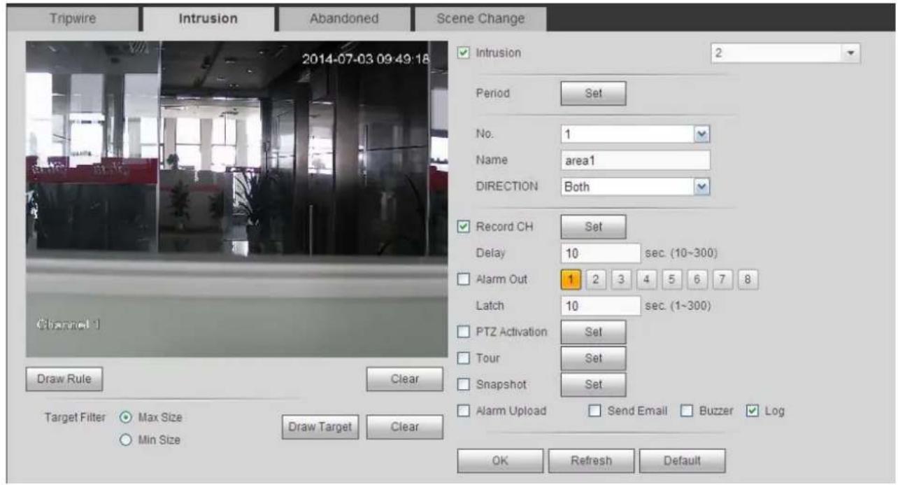
text_image
Tripwire Intrusion Abandoned Scene Change 2014-07-03 09:49:18 Channel 1 Draw Rule Clear Target Filter ○ Max Size ○ Min Size Draw Target Clear Intrusion 2 Period Set No. 1 Name area1 DIRECTION Both Record CH Set Delay 10 sec. (10~300) Alarm Out 1 2 3 4 5 6 7 8 Latch 10 sec. (1~300) PTZ Activation Set Tour Set Snapshot Set Alarm Upload Send Email Buzzer Log OK Refresh DefaultFigure 5-65
Check the Intrusion box to enable intrusion function.
Select SN (Area1/2/3/4) and direction, and then input customized rule name.
● No. and Area1/2/3/4: System supports four zones. Each SN stands for one zone.
- Direction: There are three options: A->B, B->A, both. System can generate an alarm once there is any object enter/exit (Or both) the zone.
Now you can draw a rule. Left click mouse to draw a line first and then right click mouse to draw another line until you draw a rectangle, you can right click mouse to exit.
Click Ok to complete the rule setup.
Draw Rule Click to draw the
Click to draw the zone. See Figure 5-66.
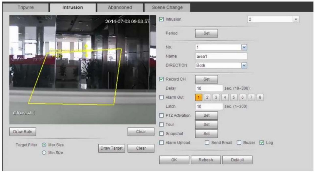
text_image
Tripwire Intrusion Abandoned Scene Change 2014-07-03 09:53:57 Channel 1 Draw Rule Clear Target Filter ○ Max Size ○ Min Size Draw Target Clear Intrusion 2 Period Set No. 1 Name area1 DIRECTION Both Record CH Set Delay 10 sec. (10~300) Alarm Out 1 2 3 4 5 6 7 8 Latch 10 sec. (1~300) PTZ Activation Set Tour Set Snapshot Set Alarm Upload Send Email Buzzer Log OK Refresh DefaultFigure 5-66
For detailed setups, please refer to chapter 5.8.3.1.1 motion detect for detailed information.
5.8.3.2.3 Object Detect
Please make sure you are connecting to the smart network camera, otherwise you can not use IVS function!
For the same channel, the object detect and the intrusion can not be valid at the same time.
From main menu->Setup->Event->IVS->Object, the object interface is shown as below. See Figure 5-67.
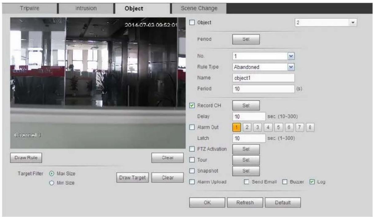
text_image
Tripwire Intrusion Object Scene Change 2014-07-03 09:52:01 Object 2 Period Set No. 1 Rule Type Abandoned Name object1 Period 10 (s) Record CH Set Delay 10 sec. (10~300) Alarm Out 1 2 3 4 5 6 7 8 Latch 10 sec. (1~300) PTZ Activation Set Tour Set Snapshot Set Alarm Upload Send Email Buzzer Log OK Refresh Default Channel 1 Draw Rule Clear Target Filter Max Size Min Size Draw Target ClearFigure 5-67
Check the Object box to enable object detect function.
Select SN (object1/2/3/4) and rule type, and then input customized rule name.
● No. and Object1/2/3/4: System supports four zones. Each SN stands for one zone.
- Rule type: Please select from the dropdown list. There are two types: Missing object detect/abandoned object detect.
- Period: It refers to the object in/out the zone time.
Draw Rule Click to draw the rule. See Figure 5-68.
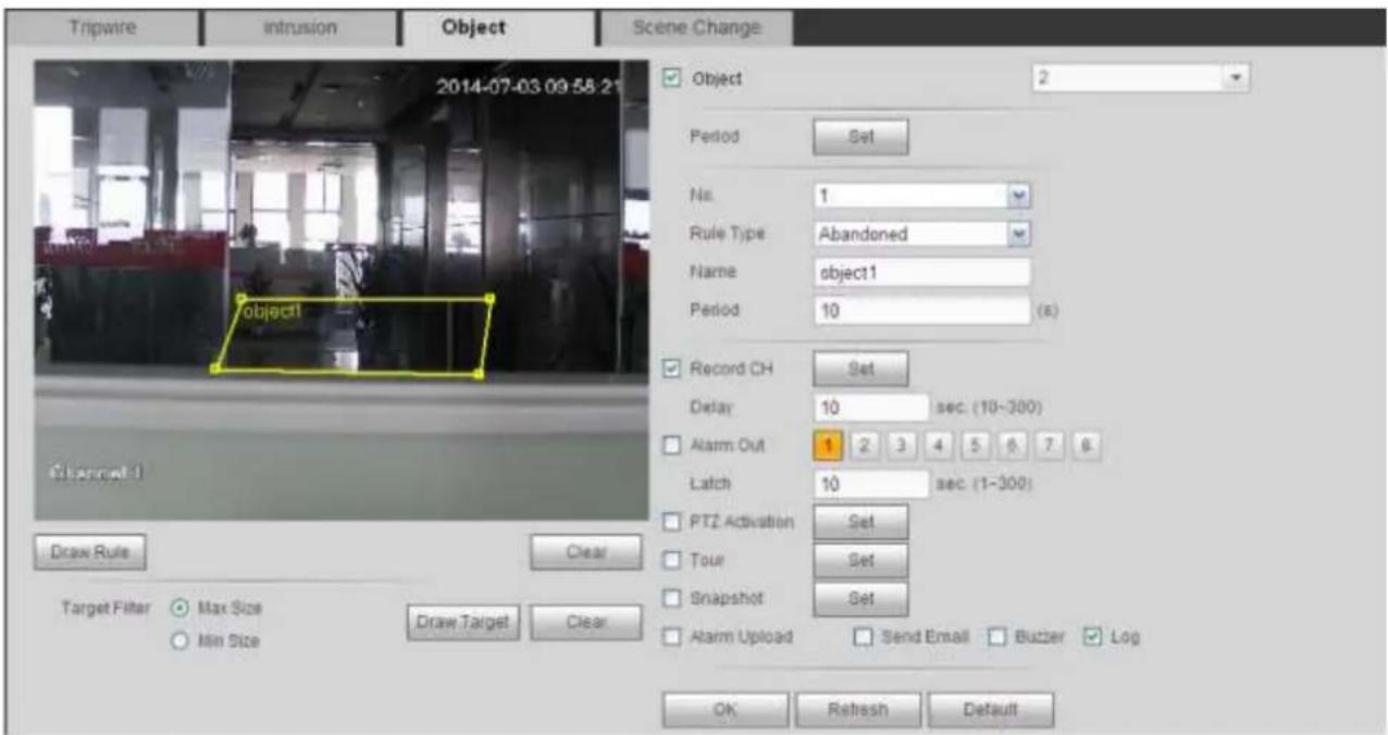
text_image
Tripwire intrusion Object Scene Change 2014-07-03 09:58:21 object1 Object 2 Period Set No. 1 Rule Type Abandoned Name object1 Period 10 (8) Record CH Set Delay 10 sec. (10~300) Alarm Out 1 2 3 4 5 6 7 8 Latch 10 sec. (1~300) PTZ Activation Set Tour Set Snapshot Set Alarm Upload Send Email Buzzer Log OK Refresh Default Draw Rule Clear Target Filter Max Size Min Size Draw Target ClearFigure 5-68
Now you can draw a rule. Left click mouse to draw a line, until you draw a rectangle, you can right click mouse.
Click Ok to complete the rule setup.
For detailed setups, please refer to chapter 5.8.3.1.1 motion detect for detailed information.
5.8.3.2.4 Change Scene
Please make sure you are connecting to the smart network camera, otherwise you can not use IVS function!
When the detected scene changes, ,the system can generate an alarm. From main menu->Setup->Event->IVS->Change scene, the interface is shown as in Figure 5-69.
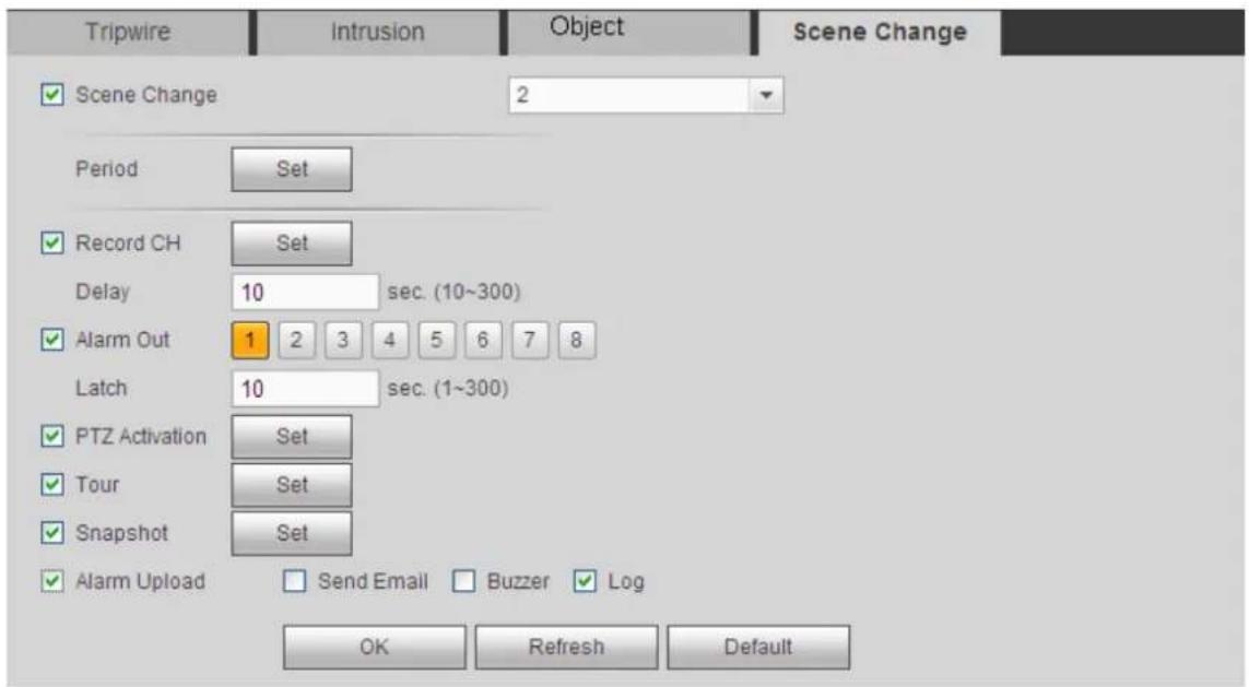
text_image
Tripwire Intrusion Object Scene Change ✓ Scene Change 2 Period Set ✓ Record CH Set Delay 10 sec. (10~300) ✓ Alarm Out 1 2 3 4 5 6 7 8 Latch 10 sec. (1~300) ✓ PTZ Activation Set ✓ Tour Set ✓ Snapshot Set ✓ Alarm Upload Send Email Buzzer Log OK Refresh DefaultFigure 5-69
For detailed setups, please refer to chapter 5.8.3.1.1 motion detect for detailed information.
5.8.3.3 Face Detect (Optional)
Please make sure you are connecting to the smart network camera, otherwise you can not use IVS function!
When camera detects human face, system can generate an alarm.
From main menu->Setup->Event->Face detect, the interface is shown as in Figure 5-70.
- Enable face boost: Check the box here, system can enhance the human face display pane.
● Sensitivity: System supports 6 levels. The sixth level has the highest sensitivity.
For detailed setups, please refer to chapter 5.8.3.1.1.
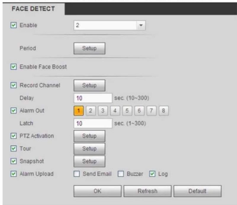
text_image
FACE DETECT Enable 2 Period Setup Enable Face Boost Record Channel Setup Delay 10 sec. (10~300) Alarm Out 1 2 3 4 5 6 7 8 Latch 10 sec. (1~300) PTZ Activation Setup Tour Setup Snapshot Setup Alarm Upload Send Email Buzzer Log OK Refresh DefaultFigure 5-70
5.8.3.4 Audio Detect (Optional)
Please make sure you are connecting to the smart network camera, otherwise you can not use IVS function!
System can generate an alarm once it detect the audio input is abnormal or audio volume changes.
From main menu->Setup->Event->Audio detect, you can see an interface shown as in Figure 5-71.
- Input abnormal: Check the box here, system can generate an alarm once the audio input is abnormal.
- Intensity change: Check the box here, system can generate an alarm once the audio volume becomes strong.
- Sensitivity: It refers to the audio recognition sensitivity. The higher the value is, the higher the sensitivity is.
- Threshold: It is to set intensity change threshold. The smaller the value is, the higher the sensitivity is.
For detailed setups, please refer to chapter 5.8.3.1.1 motion detect for detailed information.
Figure 5-71
5.8.3.5 Alarm
Before operation, please make sure you have properly connected alarm devices such as buzzer. The input mode includes local alarm and network alarm.
5.8.3.5.1 Local Alarm
The local alarm interface is shown as in Figure 5-72. It refers to alarm from the local device.
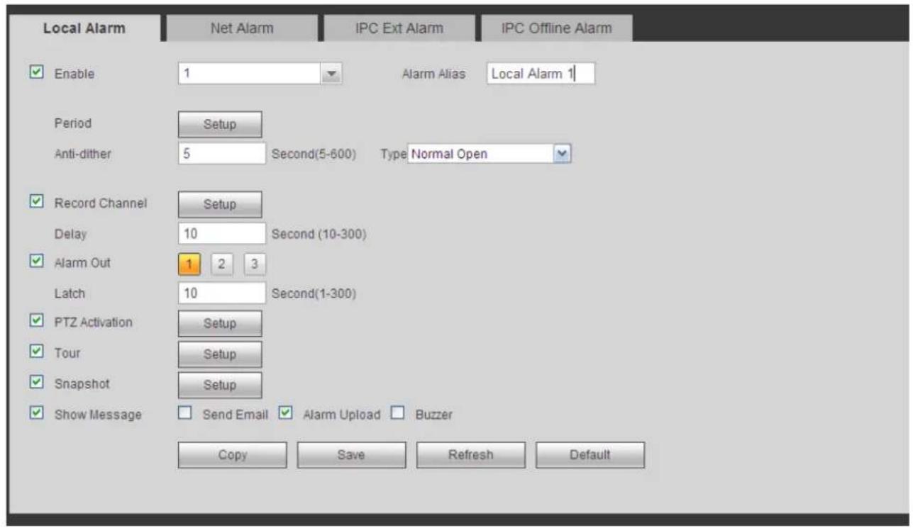
text_image
Local Alarm Enable 1 Alarm Alias Local Alarm 1 Period Setup Anti-dither 5 Second(5-600) Type Normal Open Record Channel Setup Delay 10 Second (10-300) Alarm Out 1 2 3 Latch 10 Second(1-300) PTZ Activation Setup Tour Setup Snapshot Setup Show Message Send Email Alarm Upload Buzzer Copy Save Refresh DefaultFigure 5-72
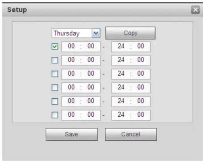
text_image
Setup Thursday Copy 00 : 00 - 24 : 00 00 : 00 - 24 : 00 00 : 00 - 24 : 00 00 : 00 - 24 : 00 00 : 00 - 24 : 00 00 : 00 - 24 : 00 00 : 00 - 24 : 00 Save CancelFigure 5-73
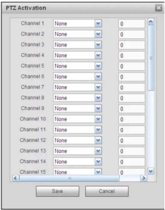
text_image
PTZ Activation Channel 1 None 0 Channel 2 None 0 Channel 3 None 0 Channel 4 None 0 Channel 5 None 0 Channel 6 None 0 Channel 7 None 0 Channel 8 None 0 Channel 9 None 0 Channel 10 None 0 Channel 11 None 0 Channel 12 None 0 Channel 13 None 0 Channel 14 None 0 Channel 15 None 0 Save CancelFigure 5-74
Please refer to the following sheet for detailed information.
| Parameter | Function |
| Enable | You need to check the box to enable this function.Please select a channel from the dropdown list. |
| Period | This function becomes activated in the specified periods.There are six periods in one day. Please draw a circle to enable corresponding period.Select date. If you do not select, current setup applies to today only. You can select all week column to apply to the whole week.Click OK button, system goes back to local alarm interface, please click save button to exit. |
| Anti-dither | System only memorizes one event during the anti-dither period. The value ranges from 5s to 600s. |
| Sensor type | There are two options: NO/NC. |
| Record channel | System auto activates motion detection channel(s) to record once an alarm occurs. Please note you need to set alarm record period and go to Storage-> Schedule to set current channel as schedule record. |
| Record Delay | System can delay the record for specified time after alarm ended. The value ranges from 10s to 300s. |
| Alarm out | Enable alarm activation function. You need to select alarm output port so that system can activate corresponding alarm device when an alarm occurs. |
| Latch | System can delay the alarm output for specified time after an alarm ended. The value ranges from 1s to 300s. |
| Show message | System can pop up a message to alarm you in the local host screen if you enabled this function. |
| Buzzer | Check the box here to enable this function. The buzzer beeps when an alarm occurs. |
| Alarm upload | System can upload the alarm signal to the centre (Including alarm centre). |
| Send Email | If you enabled this function, System can send out an email to alert you when an alarm occurs. |
| Tour | You need to click setup button to select tour channel. System begins 1-wiindow or multiple-window tour display among the channel(s) you set to record when an alarm occurs. See Figure 5-58. |
| PTZ Activation | Here you can set PTZ movement when alarm occurs. Such as go to preset X. See Figure 5-74. |
| Snapshot | Click setup button to select snapshot channel. See Figure 5-59. |
5.8.3.5.2 Net Alarm
The network alarm interface is shown as in Figure 5-75.
Network alarm refers to the alarm signal from the network. System does not anti-dither and sensor type setup. For setup information, please refer to chapter 5.8.3.5.1.
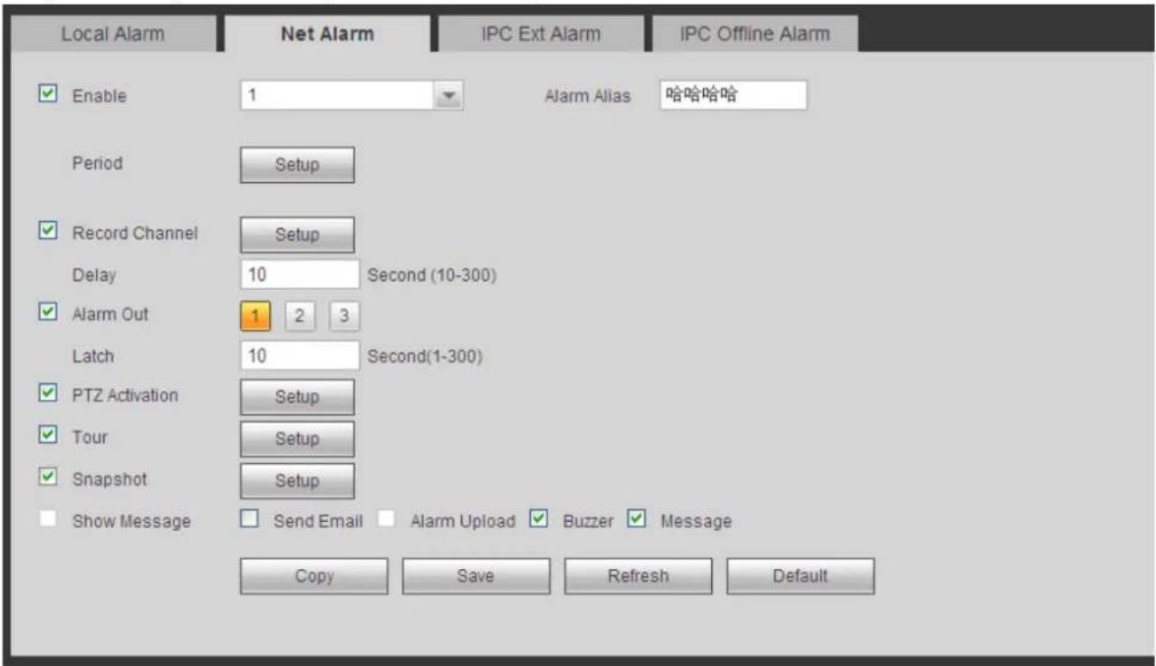
text_image
Local Alarm Enable 1 Period Setup Record Channel Setup Delay 10 Second (10-300) Alarm Out 1 2 3 Latch 10 Second(1-300) PTZ Activation Setup Tour Setup Snapshot Setup Show Message Send Email Alarm Upload Copy Save Refresh Buzzer Message IPC Ext Alarm IPC Offline Alarm Enable Alias 哈哈哈Figure 5-75
5.8.3.5.3 IPC external alarm
The IPC external alarm interface is shown as in Figure 5-76.
Network alarm refers to the alarm signal from the network. System does not anti-dither and sensor type
setup. For setup information, please refer to chapter 5.8.3.5.1.
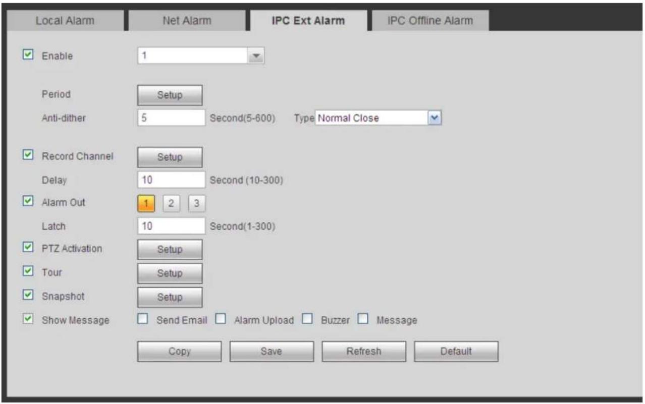
text_image
Local Alarm Enable 1 Period Setup Anti-dither 5 Second(5-600) Type Normal Close Record Channel Setup Delay 10 Second (10-300) Alarm Out 1 2 3 Latch 10 Second(1-300) PTZ Activation Setup Tour Setup Snapshot Setup Show Message Send Email Alarm Upload Buzzer Message Copy Save Refresh DefaultFigure 5-76
5.8.3.5.4 IPC Offline Alarm
The IPC offline alarm interface is shown as in Figure 5-77.
System can generate an alarm once the network camera is offline. For setup information, please refer to chapter 5.8.3.5.1.
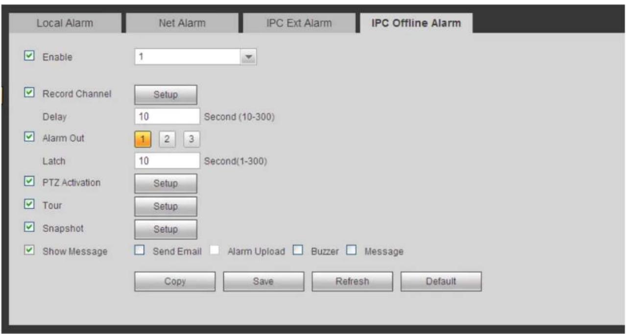
text_image
Local Alarm Enable 1 Record Channel Setup Delay 10 Second (10-300) Alarm Out 1 2 3 Latch 10 Second(1-300) PTZ Activation Setup Tour Setup Snapshot Setup Show Message Send Email Alarm Upload Buzzer Message Copy Save Refresh DefaultFigure 5-77
5.8.3.6 Abnormality
It includes six types: No disk, disk error, disks no space, disconnect, IP conflict, MAC conflict. See Figure 5-78 through Figure 5-83.
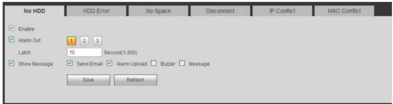
text_image
No HDD HDD Error No Space Disconnect IP Conflict MAC Conflict Enable Alarm Out 1 2 3 Latch 10 Second(1-300) Show Message Send Email Alarm Upload Buzzer Message Save RefreshFigure 5-78
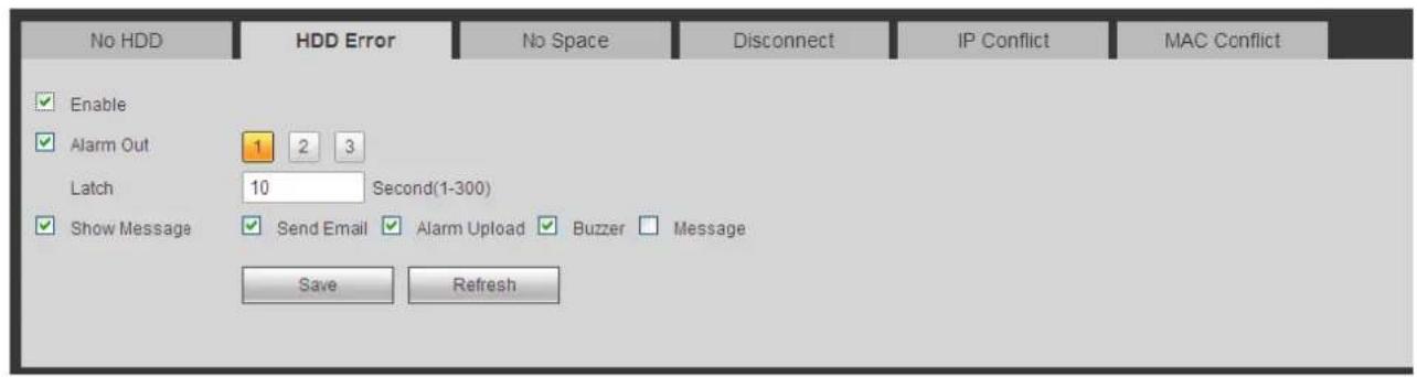
text_image
No HDD HDD Error No Space Disconnect IP Conflict MAC Conflict Enable Alarm Out 1 2 3 Latch 10 Second(1-300) Show Message Send Email Alarm Upload Buzzer Message Save RefreshFigure 5-79
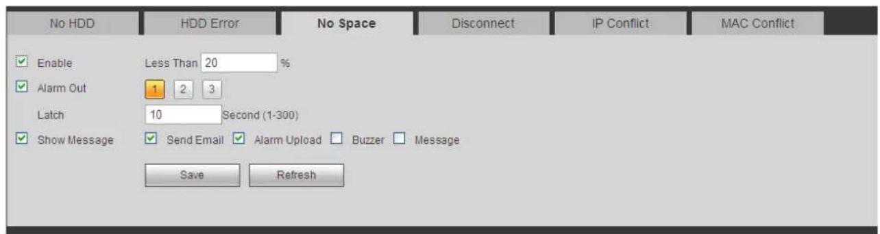
text_image
No HDD HDD Error No Space Disconnect IP Conflict MAC Conflict Enable Less Than 20 % Alarm Out 1 2 3 Latch 10 Second (1-300) Show Message Send Email Alarm Upload Buzzer Message Save RefreshFigure 5-80
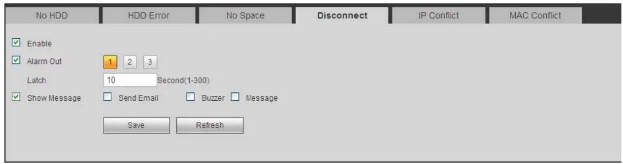
text_image
No HDD HDD Error No Space Disconnect IP Conflict MAC Conflict Enable Alarm Out 1 2 3 Latch 10 Second(1-300) Show Message Send Email Buzzer Message Save RefreshFigure 5-81
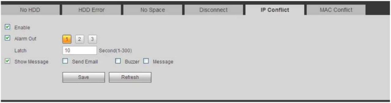
text_image
No HDD HDD Error No Space Disconnect IP Conflict MAC Conflict Enable Alarm Out 1 2 3 Latch 10 Second(1-300) Show Message Send Email Buzzer Message Save RefreshFigure 5-82
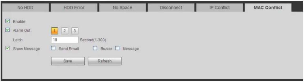
text_image
No HDD HDD Error No Space Disconnect IP Conflict MAC Conflict Enable Alarm Out 1 2 3 Latch 10 Second(1-300) Show Message Send Email Buzzer Message Save RefreshFigure 5-83
Please refer to the following sheet for detailed information.
| Parameter | Function |
| Event Type | The abnormal events include: No disk, disk error, disk no space, net disconnection, IP conflict and MAC conflict.You can set one or more items here.Less than: You can set the minimum percentage value here (For disk not space only). The device can alarm when capacity is not sufficient.You need to draw a circle to enable this function. |
| Enable | Check the box here to enable selected function. |
| Alarm Out | Please select corresponding alarm output channel when an alarm occurs. You need to check the box to enable this function. |
| Latch | The alarm output can delay for the specified time after an alarm stops.The value ranges from 1s to 300s. |
| Show message | System can pop up a message to alarm you in the local host screen if you enabled this function. |
| Alarm upload | System can upload the alarm signal to the centre (Including alarm centre. |
| Send Email | If you enabled this function, System can send out an email to alert you when an alarm occurs. |
| Buzzer | Check the box here to enable this function. The buzzer beeps when an alarm occurs. |
5.8.4 Storage
5.8.4.1 Schedule
In this interfaces, you can add or remove the schedule record setup. See Figure 5-84.
There are four record modes: general (auto), motion detect, alarm and MD&alarm. There are six periods in one day.
You can view the current time period setup from the color bar.
- Green color stands for the general record/snapshot.
● Yellow color stands for the motion detect record/snapshot..
● Red color stands for the alarm record/snapshot. - Blue color stands for MD&alarm record/snapshot.
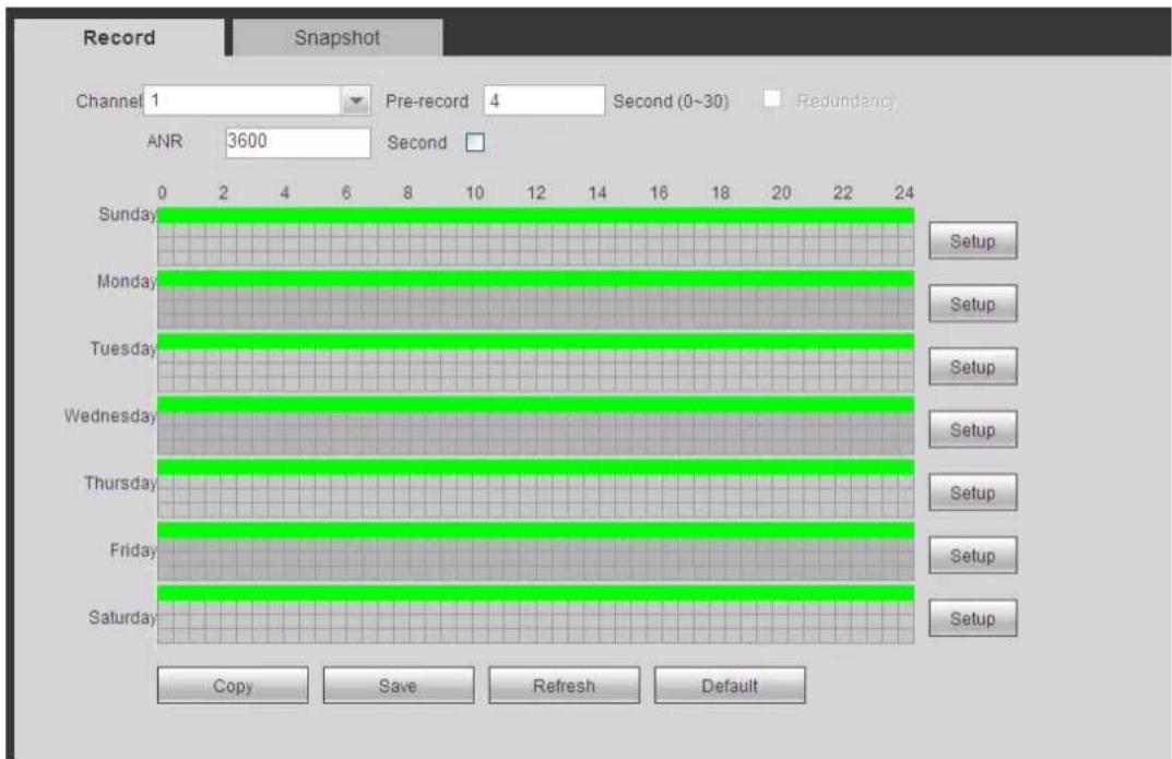
text_image
Record Snapshot Channel 1 Pre-record 4 Second (0~30) ANDR 3600 Second Redundancy Sunday Monday Tuesday Wednesday Thursday Friday Saturday Setup Setup Setup Setup Setup Setup Copy Save Refresh DefaultFigure 5-84
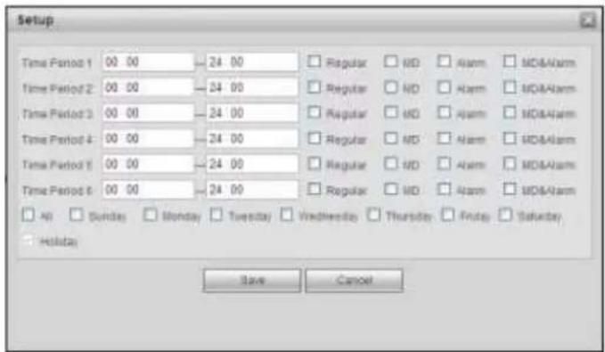
text_image
Setup Time Period 1 00 00 24 00 Regular MD Alarm MD&Alarm Time Period 2 00 00 24 00 Regular MD Alarm MD&Alarm Time Period 3 00 00 24 00 Regular MD Alarm MD&Alarm Time Period 4 00 00 24 00 Regular MD Alarm MD&Alarm Time Period 5 00 00 24 00 Regular MD Alarm MD&Alarm Time Period 6 00 00 24 00 Regular MD Alarm MD&Alarm All Sunday Monday Tuesday Wednesday Thursday Friday Saturday Holiday Save CancelFigure 5-85
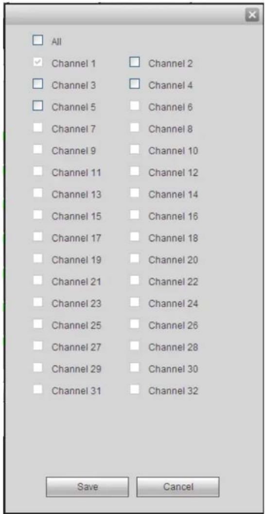
text_image
All Channel 1 Channel 2 Channel 3 Channel 4 Channel 5 Channel 6 Channel 7 Channel 8 Channel 9 Channel 10 Channel 11 Channel 12 Channel 13 Channel 14 Channel 15 Channel 16 Channel 17 Channel 18 Channel 19 Channel 20 Channel 21 Channel 22 Channel 23 Channel 24 Channel 25 Channel 26 Channel 27 Channel 28 Channel 29 Channel 30 Channel 31 Channel 32 Save CancelFigure 5-86
Please refer to the following sheet for detailed information.
| Parameter | Function |
| Channel | Please select a channel from the dropdown list. |
| Pre-record | Please input pre-record time here. The value ranges from 0 to 30. |
| Redundancy | Check the box here to enable redundancy function. Please note this function is null if there is only one HDD. |
| Snapshot | Check the box here to enable snapshot function. |
| Holiday | Check the box here to enable holiday function. |
| Setup | Click the Setup button, you can set record period. See Figure 5-85. There are six periods in one day. If you do not check the date at the bottom of the interface, current setup is for today only.Please click Save button and then exit. |
| Copy | Copy function allows you to copy one channel setup to another. After setting in channel, click Copy button, you can go to interface Figure 5-86. You can see current channel name is grey such as channel 1. Now you can select the channel you want to paste such as channel5/6/7. If you want to save current setup of channel 1 to all channels, you can click the first box “ALL”. Click the OK button to save current copy setup. Click the OK button in the Encode interface, the copy function succeeded. |
5.8.4.2 HDD Manager
5.8.4.2.1 Local Storage
The local interface is shown as in Figure 5-87. Here you can see HDD information. You can also operate the read-only, read-write, redundancy (if there are more than on HDD) and format operation.
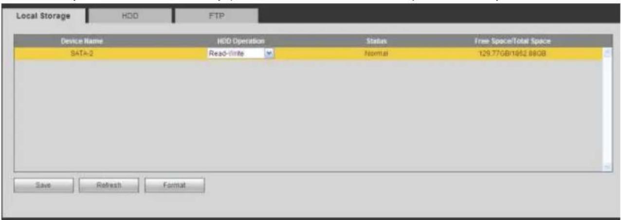
text_image
Local Storage HDD FTP Device Name HDD Operation Status Free Space/Total Space SATA-2 Read-write Normal 129.77GB/1962.88GB Save Refresh FormatFigure 5-87
5.8.4.2.2 HDD
The HDD interface is to set HDD group. See Figure 5-88.

text_image
Local Storage HDD FTP HDD HDD Group 1 - 2 1 Save RefreshFigure 5-88
5.8.4.2.3 FTP
The FTP interface is to set FTP information. See Figure 5-89.
Please set the FTP as your remote storage location. System can save record file or snapshot picture to the FTP once the network is offline or malfunction.
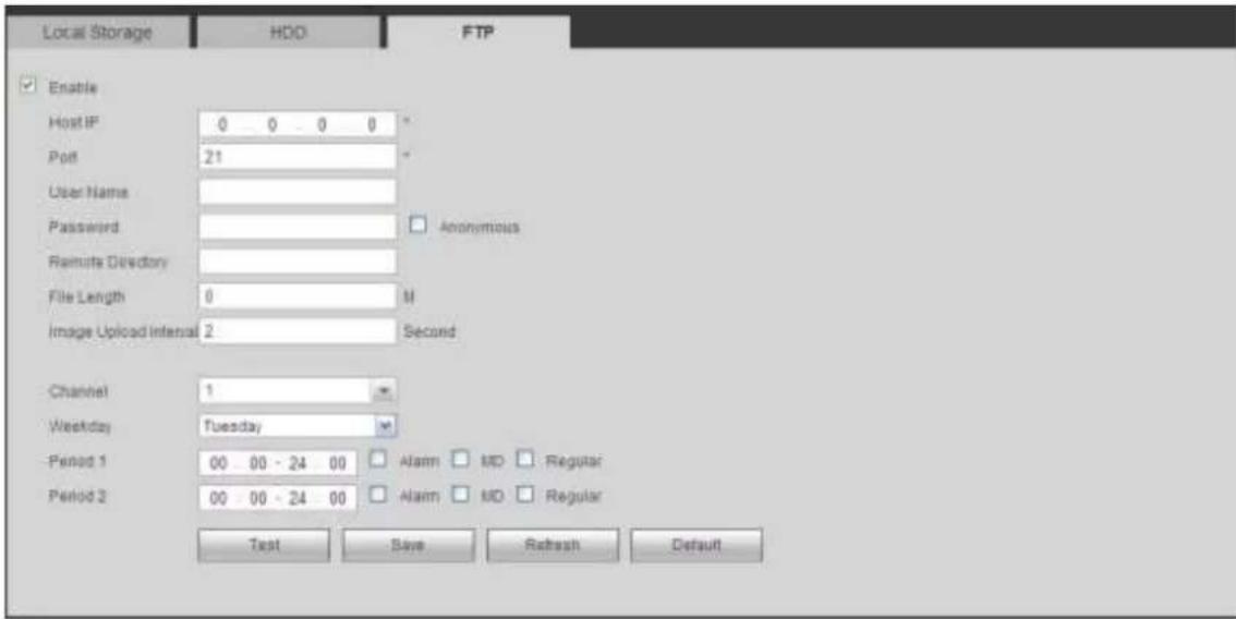
text_image
Local Storage HDD FTP Enable Host IP 0 0 0 0 * Port 21 User Name Password Anonymous Remote Directory File Length 0 M Image Upload Interval 2 Second Channel 1 Weekday Tuesday Period 1 00 00 - 24 00 Alarm MD Regular Period 2 00 00 - 24 00 Alarm MD Regular Test Save Refresh DefaultFigure 5-89
5.8.4.3 Record Control
The interface is shown as in Figure 5-90.
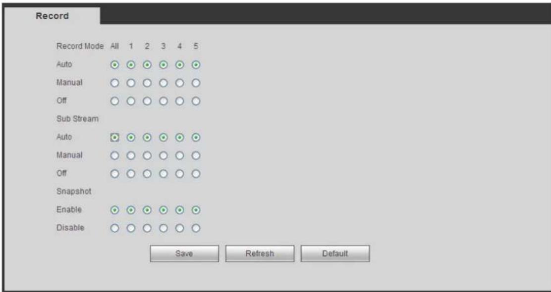
text_image
Record Record Mode All 1 2 3 4 5 Auto Manual Off Sub Stream Auto Manual Off Snapshot Enable Disable Save Refresh DefaultFigure 5-90
Please refer to the following sheet for detailed information.
| Parameter | Function |
| Channel | Here you can view channel number.The number displayed here is the max channel amount of your device. |
| Status | There are three statuses: schedule, manual and stop. |
| Schedule | System enables auto record function as you set in record schedule setup (general, motion detect and alarm). |
| Manual | It has the highest priority. Enable corresponding channel to record no matter what period applied in the record setup. |
| Stop | Stop current channel record no matter what period applied in the record setup. |
| Start all/stop all | Check the corresponding All button, you can enable or disable all channels record. |
5.8.4.4 RAID Manager
Important
Please make sure your purchased product support the RAID function, otherwise you can not see the following interface.
5.8.4.4.1 RAID Config
It is for you to manage RAID HDD. It can display RAID name, type, free space, total space, status and etc. Here you can add/delete RAID HDD.
Click Add button to select RAID type and then select HDDs, click OK button to add. See Figure 5-91.
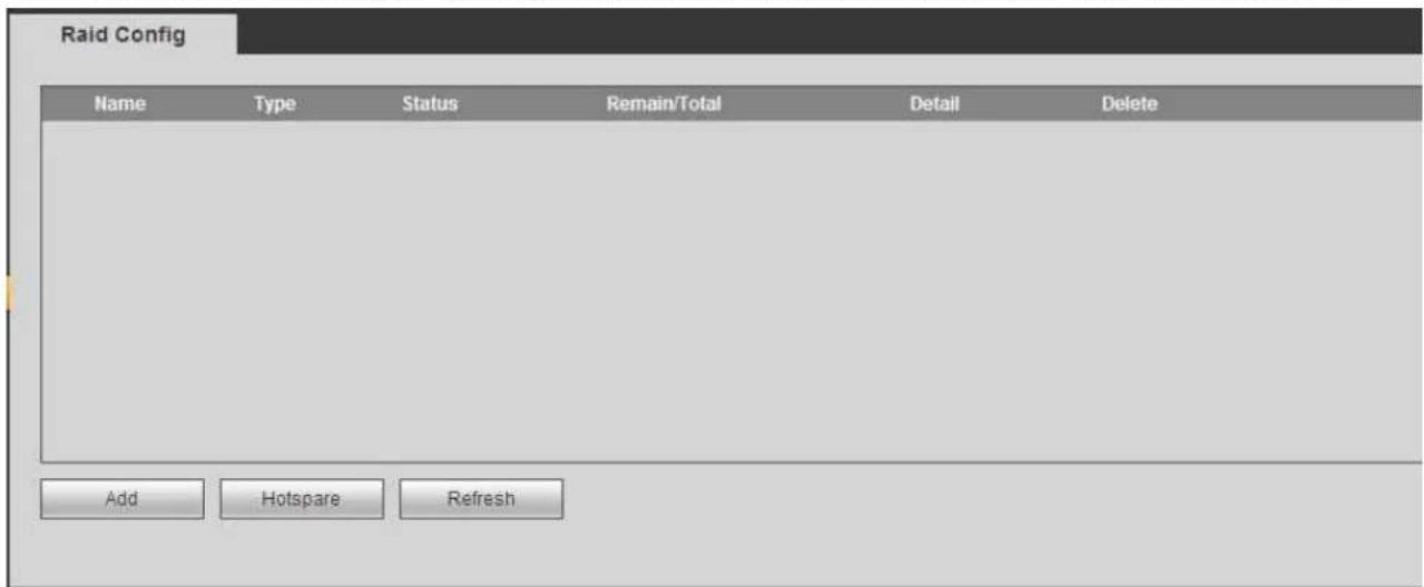
text_image
Raid Config Name Type Status Remain/Total Detail Delete Add Hotspare RefreshFigure 5-91
5.8.4.4.2 Hotspare disks
In Figure 5-91, click hotspare button, you can add the hot spare HDD. See Figure 5-92. The type includes two options:
- Global: It is global hotspare disk. When any RAID becomes degrading, it can replace and build the RAID.
- Local: It is local hotspare disk. When the specified RAID becomes degrading, it can replace and build the RAID.
Select a hot spare device and then click Delete button. Click Apply button to delete.
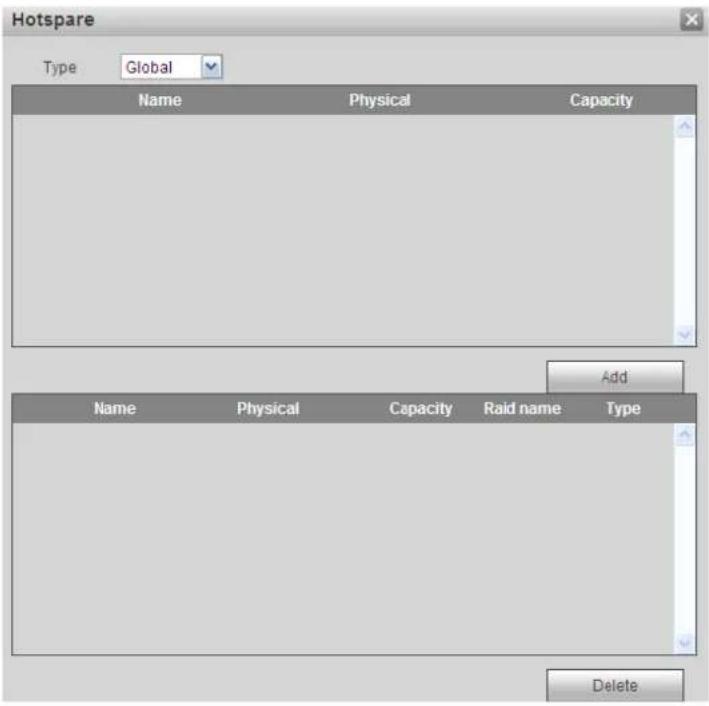
text_image
Hotspare Type: Global Name Physical Capacity Add Name Physical Capacity Raid name Type DeleteFigure 5-92
5.8.4.5 Storage
5.8.4.5.1 Main Stream
The main stream interface is shown as in Figure 5-93. Here you can set corresponding HDD group to save main stream.
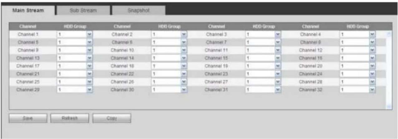
text_image
Main Stream Sub Stream Snapshot Channel HDD Group Channel HDD Group Channel HDD Group Channel 1 Channel 2 Channel 3 Channel 4 Channel 5 Channel 6 Channel 7 Channel 8 Channel 9 Channel 10 Channel 11 Channel 12 Channel 13 Channel 14 Channel 15 Channel 16 Channel 17 Channel 18 Channel 19 Channel 20 Channel 21 Channel 22 Channel 23 Channel 24 Channel 25 Channel 26 Channel 27 Channel 28 Channel 29 Channel 30 Channel 31 Channel 32 Save Refresh CopyFigure 5-93
5.8.4.5.2 Sub Stream
The sub stream interface is shown as in Figure 5-94.
Here you can set corresponding HDD group to save sub stream.
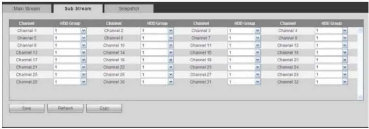
text_image
Main Stream Sub Stream Snapshot Channel HDD Group Channel HDD Group Channel HDD Group Channel HDD Group Channel 1 Channel 2 Channel 3 Channel 4 Channel 5 Channel 6 Channel 7 Channel 8 Channel 9 Channel 10 Channel 11 Channel 12 Channel 13 Channel 14 Channel 15 Channel 16 Channel 17 Channel 18 Channel 19 Channel 20 Channel 21 Channel 22 Channel 23 Channel 24 Channel 25 Channel 26 Channel 27 Channel 28 Channel 29 Channel 30 Channel 31 Channel 32 Save Refresh CopyFigure 5-94
5.8.4.5.3 Snapshot
The snapshot interface is shown as in Figure 5-95. Here you can set corresponding HDD group to save snapshot picture.
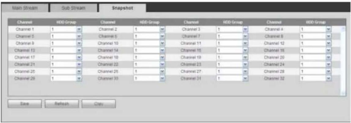
text_image
Main Stream Sub Stream Snapshot Channel HDD Group Channel HDD Group Channel HDD Group Channel HDD Group Channel 1 Channel 2 Channel 3 Channel 4 Channel 5 Channel 6 Channel 7 Channel 8 Channel 9 Channel 10 Channel 11 Channel 12 Channel 13 Channel 14 Channel 15 Channel 16 Channel 17 Channel 18 Channel 19 Channel 20 Channel 21 Channel 22 Channel 23 Channel 24 Channel 25 Channel 26 Channel 27 Channel 28 Channel 29 Save Refresh CopyFigure 5-95
5.8.5 Setting
5.8.5.1 General
The general interface includes general, date/time and holiday setup.
5.8.5.1.1 General
The general interface is shown as in Figure 5-96.
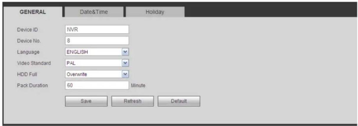
text_image
GENERAL Date&Time Holiday Device ID NVR Device No. 8 Language ENGLISH Video Standard PAL HDD Full Overwrite Pack Duration 60 Minute Save Refresh DefaultFigure 5-96
Please refer to the following sheet for detailed information.
| Parameter | Function |
| Device ID | It is to set device name. |
| Device No. | It is device channel number. |
| Language | You can select the language from the dropdown list.Please note the device needs to reboot to get the modification activated. |
| Video Standard | This is to display video standard such as PAL. |
| HDD full | Here is for you to select working mode when hard disk is full. There are two options: stop recording or rewrite. If current working HDD is overwritten or the current HDD is full while the next HDD is no empty, then system stops recording, If the current HDD is full and then next HDD is not empty, then system overwrites the previous files. |
| Pack duration | Here is for you to specify record duration. The value ranges from 1 to 120 minutes. Default value is 60 minutes. |
5.8.5.1.2 Date and time
The date and time interface is shown as in Figure 5-97
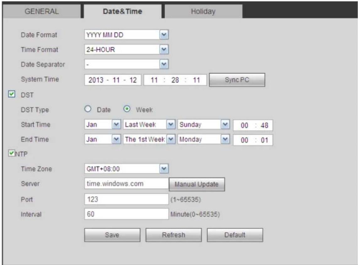
text_image
GENERAL Date&Time Holiday Date Format YYYY MM DD Time Format 24-HOUR Date Separator - System Time 2013 - 11 - 12 11 : 28 : 11 Sync PC ✓ DST DST Type ○ Date ● Week Start Time Jan Last Week Sunday 00 : 48 End Time Jan The 1st Week Monday 00 : 01 ✓ NTP Time Zone GMT+08:00 Server time.windows.com Manual Update Port 123 (1~65535) Interval 60 Minute(0~65535) Save Refresh DefaultFigure 5-97
Please refer to the following sheet for detailed information.
| Parameter | Function |
| Date format | Here you can select date format from the dropdown list. |
| Time Format | There are two options: 24-H and 12-H. |
| Time zone | The time zone of the device. |
| System time | It is to set system time. It becomes valid after you set. |
| Sync PC | You can click this button to save the system time as your PC current time. |
| DST | Here you can set day night save time begin time and end time. You can set according to the date format or according to the week format. |
| NTP | You can check the box to enable NTP function. |
| NTP server | You can set the time server address. |
| Port | It is to set the time server port. |
| Interval | It is to set the sync periods between the device and the time server. |
5.8.5.1.3 Holiday Setup
Holiday setup interface is shown as in Figure 5-98.
Here you can click Add holidays box to add a new holiday and then click Save button to save.
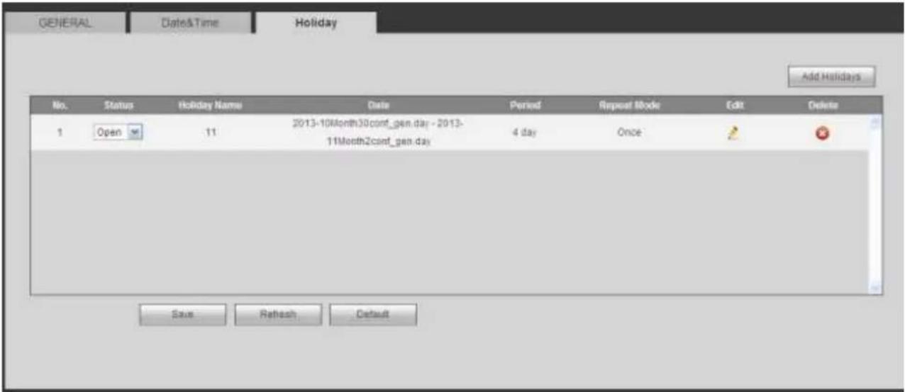
text_image
GENERAL Date&Time Holiday Add Holidays No. Status Holiday Name Date Period Repeat Mode Edit Delete 1 Open 11 2013-10Month30conf_gen.day - 2013- 11Month2conf_gen.day 4 day Once Save Refresh DefaultFigure 5-98
5.8.5.2 Account
Note:
- For the character in the following user name or the user group name, system max supports 6-digits. The space in the front or at the end of the string is null. The valid string includes: character, number, and underline.
- The user amount default setup is 64 and the group amount default setup is 20. The factory default setup includes two levels: user and admin. You can set the corresponding group and then set the rights for the respective user in the specified groups.
- User management adopts group/user modes. The user name and the group name shall be unique. One user shall be included in only one group.
5.8.5.2.1 User name
In this interface you can add/remove user and modify user name. See Figure 5-99.
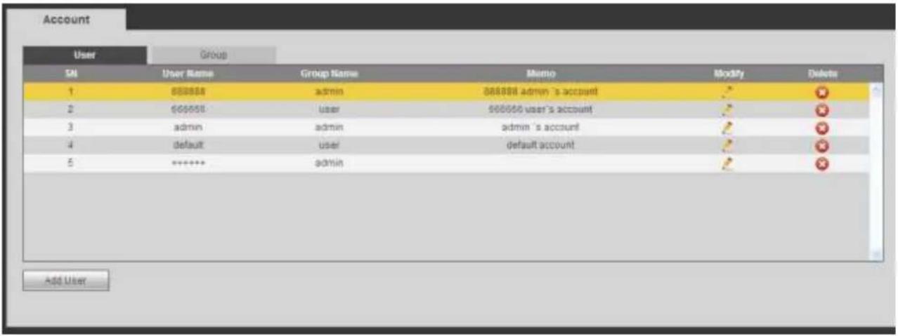
text_image
Account User Group SN User Name Group Name Memo Modify Delete 1 888888 admin 888888 admin 's account 2 666666 user 966666 user's account 3 admin admin admin 's account 4 default user default account 5 ****** admin Add UserFigure 5-99
Add user: It is to add a name to group and set the user rights. See Figure 5-100.
There are three default users: admin/888888 and hidden user "default".
Hidden user "default" is for system interior use only and can not be deleted. When there is no login user, hidden user "default" automatically login. You can set some rights such as monitor for this user so that you can view some channel view without login.
Here you can input the user name and password and then select one group for current user.
Please note the user rights shall not exceed the group right setup.
For convenient setup, please make sure the general user has the lower rights setup than the admin.
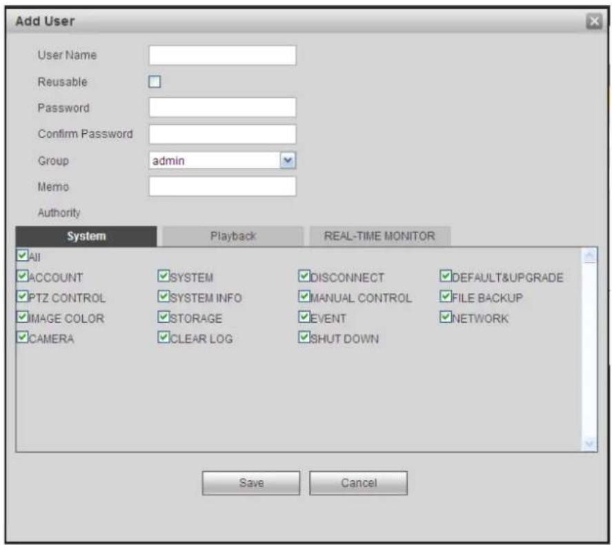
text_image
Add User User Name Reusable Password Confirm Password Group admin Memo Authority System Playback REAL-TIME MONITOR ✓ All ✓ ACCOUNT SYSTEM ✓ DISCONNECT ✓ DEFAULT&UPGRADE ✓ PTZ CONTROL SYSTEM INFO ✓ MANUAL CONTROL ✓ FILE BACKUP ✓ IMAGE COLOR ✓ STORAGE ✓ EVENT ✓ NETWORK ✓ CAMERA CLEAR LOG ✓ SHUT DOWN Save CancelFigure 5-100
Modify user
It is to modify the user property, belonging group, password and rights. See Figure 5-101.
Modify password
It is to modify the user password. You need to input the old password and then input the new password twice to confirm the new setup. Please click the OK button to save.
Please note, the password ranges from 1-digit to 6-digit. It shall include the number only. For the user of the account rights, he can modify the password of other users.
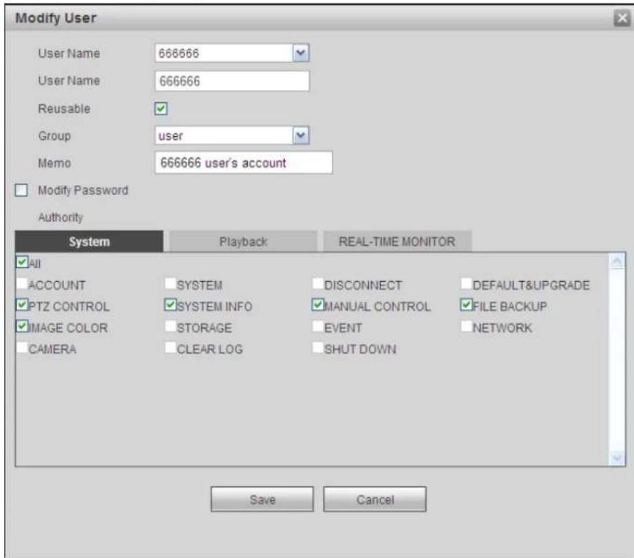
text_image
Modify User User Name 666666 User Name 666666 Reusable ✓ Group user Memo 666666 user's account ✓ Modify Password Authority System Playback REAL-TIME MONITOR ✓ All ACCOUNT SYSTEM DISCONNECT DEFAULT&UPGRADE ✓ PTZ CONTROL ✓ SYSTEM INFO ✓ MANUAL CONTROL ✓ FILE BACKUP ✓ IMAGE COLOR STORAGE EVENT NETWORK CAMERA CLEAR LOG SHUT DOWN Save CancelFigure 5-101
5.8.5.2.2 Group
The group management interface can add/remove group, modify group password and etc.
The interface is shown as in Figure 5-102.
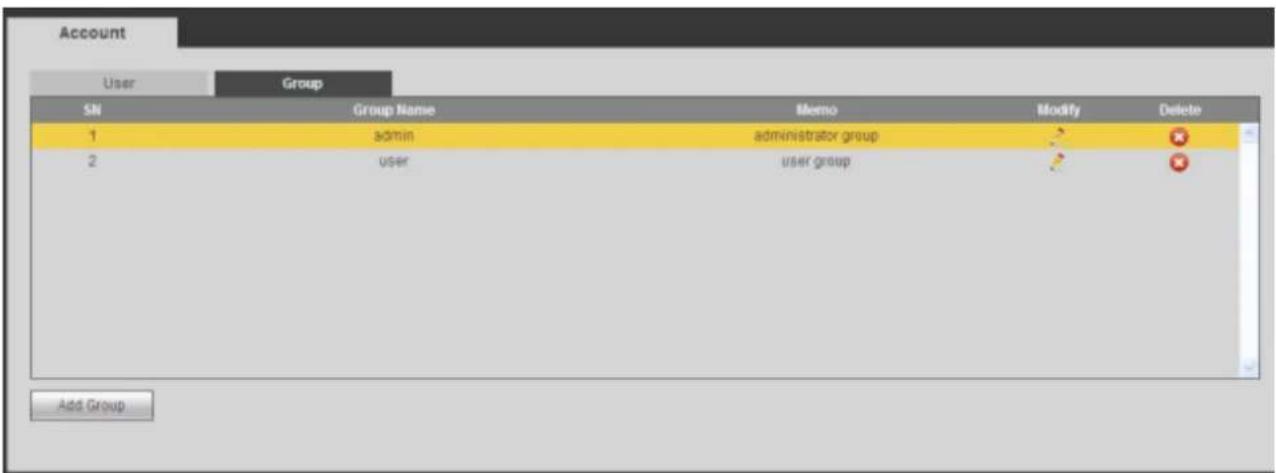
text_image
Account User Group SN Group Name Memo Modify Delete 1 adults administrator group 2 user user group Add GroupFigure 5-102
Add group: It is to add group and set its corresponding rights. See Figure 5-103.
Please input the group name and then check the box to select the corresponding rights. It includes: shutdown/reboot device, live view, record control, PTZ control and etc.
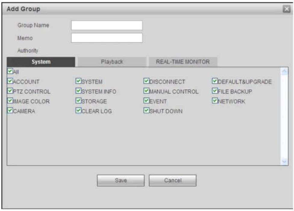
text_image
Add Group Group Name Memo Authority System Playback REAL-TIME MONITOR ✓All ✓ACCOUNT ✓SYSTEM ✓DISCONNECT ✓DEFAULT&UPGRADE ✓PTZ CONTROL ✓SYSTEM INFO ✓MANUAL CONTROL ✓FILE BACKUP ✓IMAGE COLOR ✓STORAGE ✓EVENT ✓NETWORK ✓CAMERA ✓CLEAR LOG ✓SHUT DOWN Save CancelFigure 5-103
Modify group
Click the modify group button, you can see an interface is shown as in Figure 5-104. Here you can modify group information such as remarks and rights.
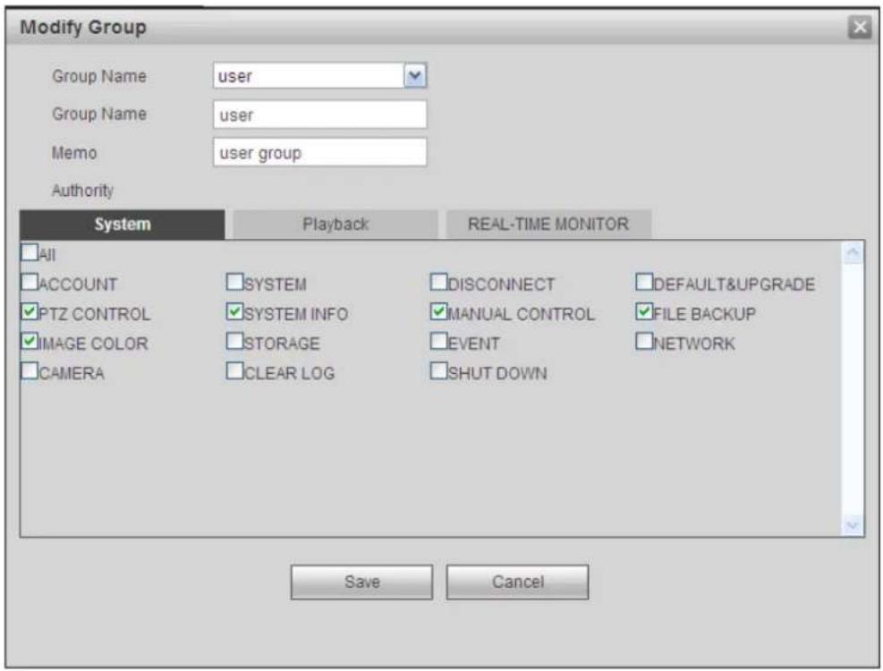
text_image
Modify Group Group Name user Group Name user Memo user group Authority System Playback REAL-TIME MONITOR All ACCOUNT SYSTEM DISCONNECT DEFAULT&UPGRADE PTZ CONTROL SYSTEM INFO MANUAL CONTROLsrFILE BACKUP IMAGE COLOR STORAGE EVENT NETWORK CAMERA CLEAR LOG SHUT DOWN Save CancelFigure 5-104
5.8.5.3 Display
Display interface includes GUI, TV adjust, Tour and zero-channel encoding.
5.8.5.3.1 Display
Here you can set background color and transparency level. See Figure 5-105.
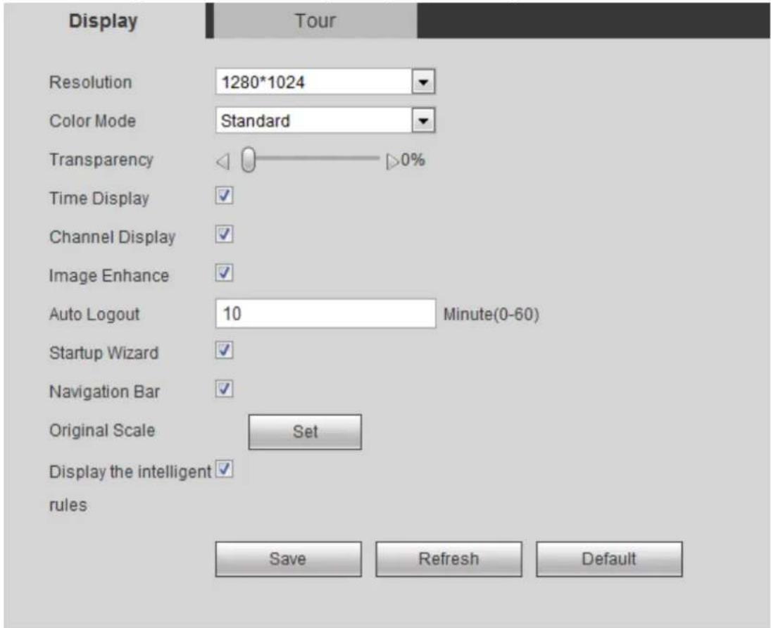
text_image
Display Tour Resolution 1280*1024 Color Mode Standard Transparency 0% Time Display ✓ Channel Display ✓ Image Enhance ✓ Auto Logout 10 Minute(0-60) Startup Wizard ✓ Navigation Bar ✓ Original Scale Set Display the intelligent ✓ rules Save Refresh DefaultFigure 5-105
Please refer to the following sheet for detailed information.
| Parameter | Function |
| Resolution | There are four options: 1920×1080, 1280×1024(default), 1280×720, 1024×768. Please note the system needs to reboot to activate current setup. |
| Color mode | Please select from the dropdown list. |
| Transparency | Here is for you to adjust transparency. The value ranges from 128 to 255. |
| Time title/channel title | Check the box here, you can view system time and channel number on the monitor video. |
| Image enhance | Check the box; you can optimize the margin of the preview video. |
| Startup wizard | Once you check the box here, system will go to the startup wizard directly when the system restarts the next time. Otherwise, it will go to the login interface. |
| Navigation bar | Check the box here, system displays the navigation bar on the interface. |
| Original scale | Click the Set button to select a channel, it can restore original scale. |
| Auto logout | Here is for you to set auto logout interval once login user remains inactive for a specified time. Value ranges from 0 to 60 minutes. 0 means there is no standby time. After the auto logout, the user needs to input user name and password to login again. |
| Display intelligent rule(s) | Check the box to enable IVS function, system can display IVS rule on the preview interface. |
5.8.5.3.2 Tour
The tour interface is shown as in Figure 5-106. Here you can set tour interval, split mode, motion detect tour and alarm tour mode.
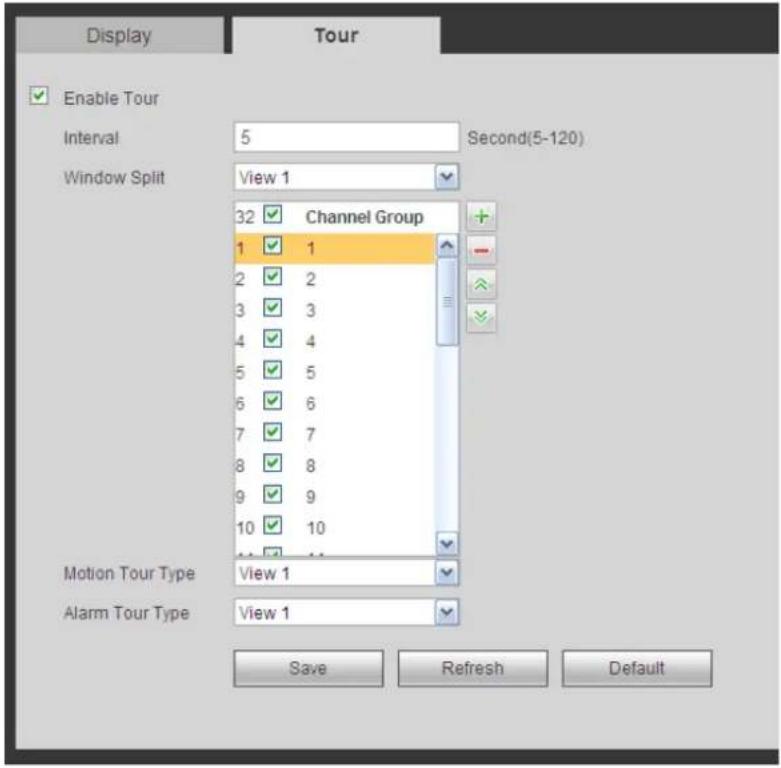
text_image
Display Tour Enable Tour Interval 5 Second(5-120) Window Split View 1 Channel Group 32 1 1 2 2 3 3 4 4 5 5 6 6 7 7 8 8 9 9 10 10 Motion Tour Type View 1 Alarm Tour Type View 1 Save Refresh DefaultFigure 5-106
Please refer to the following sheet for detailed information.
| Parameter | Function |
| Enable tour | Check the box here to enable tour function. |
| Interval | Here is for you to adjust transparency. The value ranges from 5 to 120s. The default setup is 5s. |
| Split | Here you can set window mode and channel group. System can support 1/4/8/9/16/25/36-window according to device channel amount. |
| Motion tour/Alarm tour | Here you can set motion detect tour/alarm tour window mode. System supports 1/8-window now. |
5.8.5.4 Alarm Out
The alarm output interface is shown as below. See Figure 5-107
Here you can set alarm output mode: auto/manual/stop.
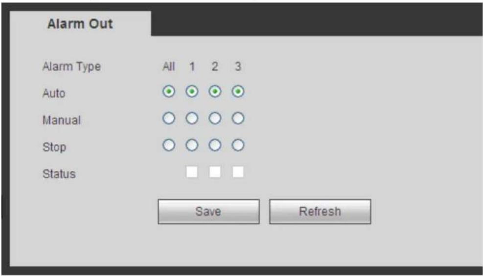
text_image
Alarm Out Alarm Type All 1 2 3 Auto Manual Stop Status Save RefreshFigure 5-107
5.8.5.5 Default
The default setup interface is shown as in Figure 5-108.
Here you can select Network/Event/Storage/Setting/Camera. Or you can check the All box to select all items.
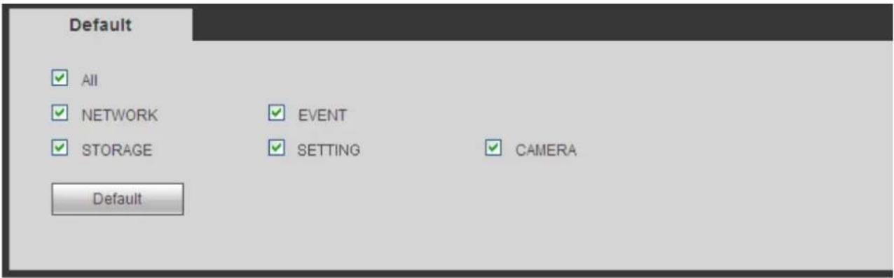
text_image
Default ✓ All ✓ NETWORK ✓ STORAGE Default ✓ EVENT ✓ SETTING ✓ CAMERAFigure 5-108
The interface is shown as in Figure 5-109. This interface is for you to export or import the configuration files.
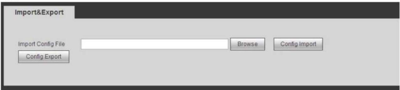
text_image
Import&Export Import Config File Config Export Browse Config ImportFigure 5-109
Please refer to the following sheet for detailed information.
| Parameter | Function |
| Browse | Click to select import file. |
| Import | It is to import the local setup files to the system. |
| Export | It is to export the corresponding WEB setup to your local PC. |
5.8.5.7 Auto maintain
The auto maintain interface is shown as in Figure 5-110.
Here you can select auto reboot and auto delete old files interval from the dropdown list.
If you want to use the auto delete old files function, you need to set the file period.
Click Manual reboot button, you can restart device manually.
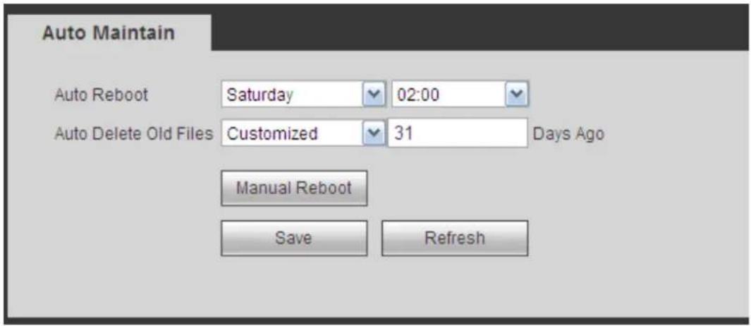
text_image
Auto Maintain Auto Reboot Saturday 02:00 Auto Delete Old Files Customized 31 Days Ago Manual Reboot Save RefreshFigure 5-110
5.8.5.8 Upgrade
The upgrade interface is shown as in Figure 5-111.
Please select the upgrade file and then click the update button to begin update. Please note the file name shall be as *.bin. During the upgrade process, do not unplug the power cable, network cable, or shutdown the device.
Important
Improper upgrade program may result in device malfunction! Please make sure the operation is operated under the supervision of the professional engineer!
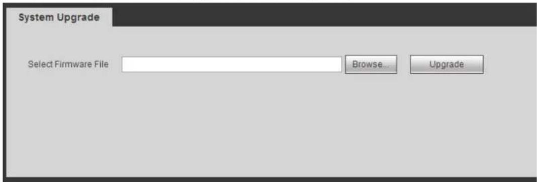
text_image
System Upgrade Select Firmware File Browse... UpgradeFigure 5-111
5.8.5.9 RS232
The RS232 interface is shown as in Figure 5-112.
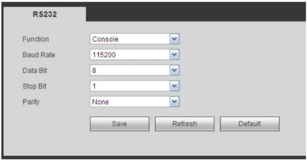
text_image
RS232 Function Console Baud Rate 115200 Data Bit 8 Stop Bit 1 Parity None Save Refresh DefaultFigure 5-112
Please refer to the following sheet for detailed information.
| Parameter | Function |
| Protocol | Select the corresponding dome protocol.Default setup is console. |
| Baud Rate | Select the baud rate.Default setup is 115200. |
| Data Bit | The value ranges from 5 to 8.Default setup is 8. |
| Stop bit | There are two options: 1/2.Default setup is 1. |
| Parity | There are five options: none/odd/even/space/mark.Default setup is none. |
5.8.5.10 PTZ
The PTZ interface is shown as in Figure 5-113 (Local) and Figure 5-114 (Remote).
Before setup, please check the following connections are right:
- PTZ and decoder connection is right. Decoder address setup is right.
- Decoder A (B) line connects with NVR A (B) line.
Click Save button after you complete setup, you can go back to the monitor interface to control speed dome.
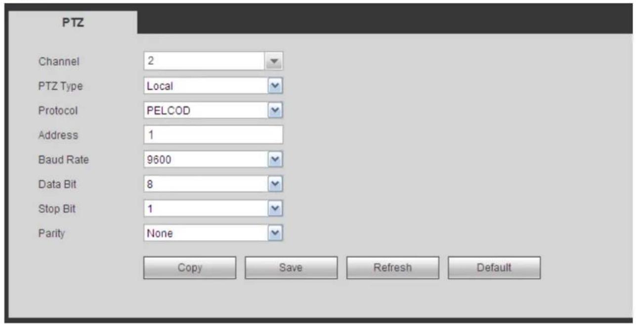
text_image
PTZ Channel 2 PTZ Type Local Protocol PELCOD Address 1 Baud Rate 9600 Data Bit 8 Stop Bit 1 Parity None Copy Save Refresh DefaultFigure 5-113
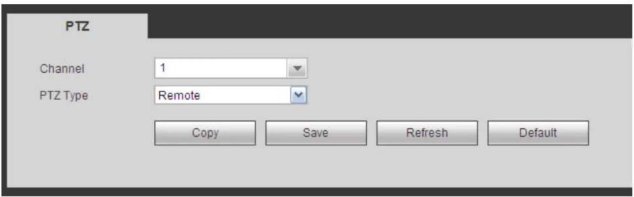
text_image
PTZ Channel 1 PTZ Type Remote Copy Save Refresh DefaultFigure 5-114
Please refer to the following sheet for detailed information.
| Parameter | Function |
| Channel | Select speed dome connected channel. |
| PTZ Type | There are two options: local/remote.Please select remote type if you are connecting to the network PTZ.Please select local type if you are using RS485 to the PTZ camera. |
| Protocol | Select the corresponding dome protocol such as PELCOD. |
| Address | Set corresponding dome address. Default value is 1.Please note your setup here shall comply with your dome address; otherwise you can not control the speed dome. |
| Baud Rate | Select the dome baud rate. Default setup is 9600. |
| Data Bit | The value ranges from 5 to 8. Default setup is 8. Please set according to the speed dome dial switch setup. |
| Stop bit | The value ranges from 1 to 2. Default setup is 1. Please set according to the speed dome dial switch setup. |
| Parity | The options include non/odd/even/space/null. Default setup is none. Please set according to the speed dome dial switch setup. |
5.9 Information
5.9.1 Version
The version interface is shown as in Figure 5-115.
Here you can view record channel, alarm input/output information, software version, release date and etc.
Please note the following information is for reference only.
| Version | |
| Record Channel: | 32 |
| Alarm In: | 8 |
| Alarm Out: | 3 |
| SN: | 000000000000000000 |
| Web: | 3.0.0.1 |
| System Version: | 3.200.0000.0 |
| Build Date: | 2013-11-07 |
Figure 5-115
5.9.2 Log
Here you can view system log. See Figure 5-116.
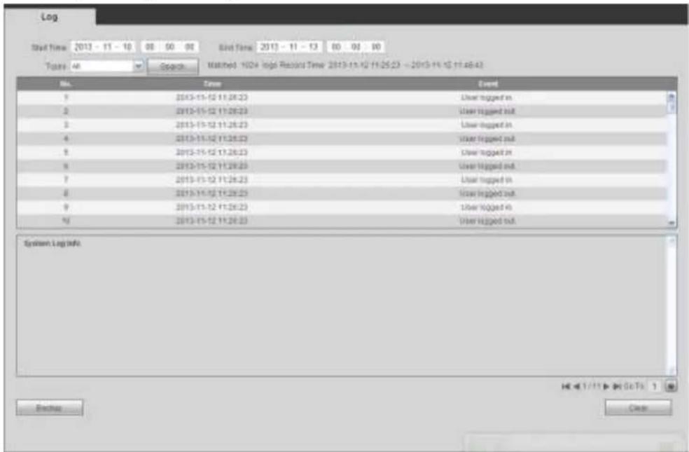
text_image
Log Start Time: 2013 - 11 - 10 00 50 90 Grid Time: 2013 - 11 - 13 80 60 80 Tops: 48 Search Matched: 102+ High Record Time: 2013-11-12 11:25:23 - 2013-11-12 11:48:43 No. Date Event 1 2013-11-12 11:26:23 User logged in 2 2013-11-12 11:26:23 User logged in 3 2013-11-12 11:26:23 User logged in 4 2013-11-12 11:26:23 User logged in 5 2013-11-12 11:26:23 User logged in 6 2013-11-12 11:26:23 User logged in 7 2013-11-12 11:26:23 User logged in 8 2013-11-12 11:26:23 User logged in 9 2013-11-12 11:26:23 User logged in 10 2013-11-12 11:26:23 User logged in System Log info. Access ClearFigure 5-116
Please refer to the following sheet for log parameter information.
| Parameter | Function |
| Type | Log types include: system operation, configuration operation, data operation, event operation, record operation, user management, log clear. |
| Start time | Set the start time of the requested log. |
| End time | Set the end time of the requested log. |
| Search | You can select log type from the drop down list and then click search button to view the list.You can click the stop button to terminate current search operation. |
| Detailed information | You can select one item to view the detailed information. |
| Clear | You can click this button to delete all displayed log files. Please note system does not support clear by type. |
| Backup | You can click this button to backup log files to current PC. |
5.9.3 Online User
The online user interface is shown as in Figure 5-117.
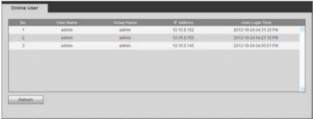
text_image
Online User No User Name Group Name IP Address User Login Time 1 admin admin 10.15.9.152 2013-10-24 04:31:33 PM 2 admin admin 10.15.9.152 2013-10-24 04:21:12 PM 3 admin admin 10.15.9.145 2013-10-24 04:50:01 PM RefreshFigure 5-117
5.10 Playback
Click Playback button, you can see an interface is shown as in Figure 5-118.
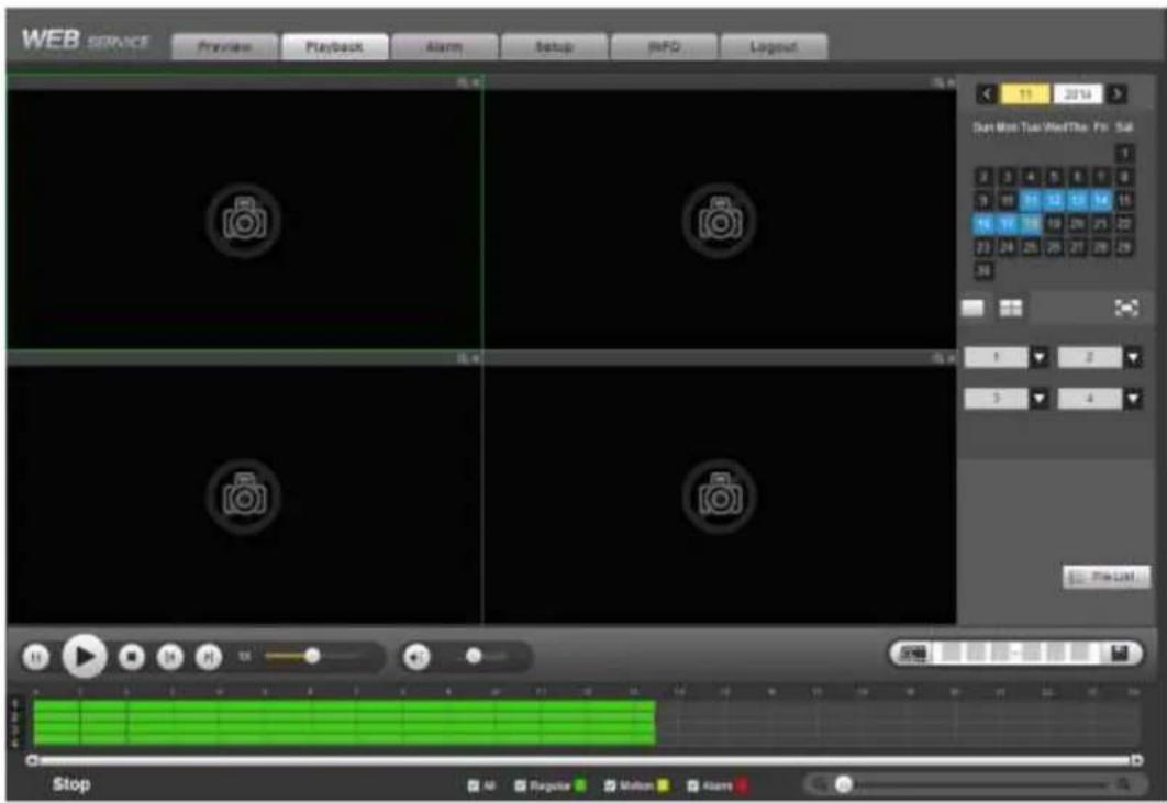
text_image
WEB SERVICE Preview Playback Alarm Setup MIFO Layout 11 2014 Set Web Tool Win/The Fri: 56 1 2 3 4 5 6 7 8 9 10 11 12 13 14 15 16 17 18 19 20 21 22 23 24 25 26 27 28 29 30 1 2 3 4 File Edit... Stop All Regular Motion AlarmsFigure 5-118
5.10.1 Search Record
Please set record type, record date, window display mode and channel name.
- Select Date
You can click the date on the right pane to select the date. The green highlighted date is system current date and the blue highlighted date means it has record files.
- Window Split
Select window split mode. Click to display in full screen. Click ESC button to exit. See Figure 5-119.

natural_image
Three gray rectangular icons: a square, a grid, and a stylized letter 'H' on a dark background (no text or symbols)Figure 5-119
- Select Channel
1\~4 means main stream and A1\~A4 means sub stream.
- Select Record Type
Check the corresponding box to select record type. See Figure 5-120.

text_image
✓ All ✓ Regular ✓ Motion ✓ AlarmFigure 5-120
5.10.2 File List
Click File list button, you can see the corresponding files in the list. See Figure 5-121.
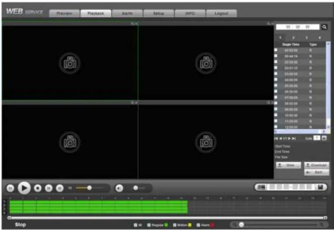
text_image
WEB SERVICE Preview Playback Alarm Setup JIFD Layout 100 00 00 1 2 3 4 Begin Time Type 00:00:00 R 00:00:14 R 00:00:30 R 00:00:52 R 00:00:66 R 00:00:80 R 00:00:92 R 00:00:96 R 00:00:98 R 00:00:99 R 00:00:99 R 00:00:99 R 15:00:00 R 15:00:00 R 12:00:00 R Start Time End Time File Set: Show Environment + Back Stop All Regular Motion AltersFigure 5-121
5.10.3 Playback
Select a file you want to play and then click Play button, system can begin playback. You can select to playback in full-screen. Please note for one channel, system can not playback and download at the same time. You can use the playback control bar to implement various operations such as play, pause, stop, slow play, fast play and etc. See Figure 5-122.
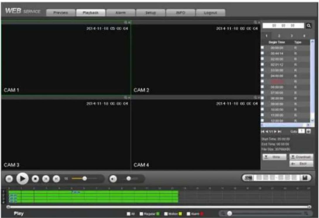
text_image
WEB SERVICE Preview Playback Alarm Setup NINFO Legend 2014-11-18 00:00:04 CAM 1 CAM 2 CAM 3 CAM 4 2014-11-18 00:00:04 2014-11-18 00:00:04 Begin Time Type 00:00:00 R 00:44:14 R 02:00:00 R 02:31:12 R 03:00:00 R 04:00:00 R 05:00:00 R 07:00:00 R 08:00:00 R 09:00:00 R 10:00:00 R 11:00:00 R 12:00:00 R Start Time: 05:00:04 End Time: 06:30:04 File Size: 30768(8x) More Download Back PlayFigure 5-122
5.10.4 Download
Select the file(s) you want to download and then click download button, you can see an interface shown as in Figure 5-123. The Download button becomes Stop button and there is a process bar for your reference. Please go to you default file saved path to view the files.
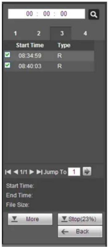
text_image
00 : 00 : 00 1 2 3 4 Start Time Type ✓ 08:34:59 R ✓ 08:40:03 R Start Time: End Time: File Size: More Stop(23%) ← BackFigure 5-123
5.10.5 Load more
It is for you to search record or picture. You can select record channel, record type and record time to download. Or you can use watermark function to verify file.
5.10.5.1 Download By File
Select channel, record type, bit stream type and then input start time and end time. Click Search button, the download by file interface is shown as in Figure 5-124.
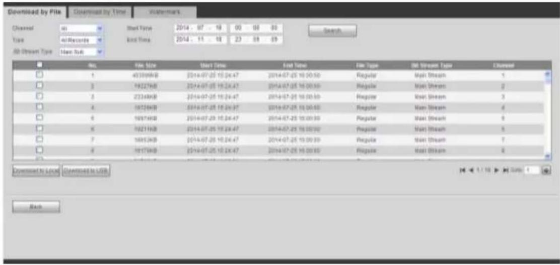
text_image
Download by Pits Downstream by Time Watermark Closed 40 Records All Stream Type Main Sub New File Size Start Time End Time File Type All Stream Type Unreaded 1 2 3 4 5 6 7 8 9 10 11 12 13 14 15 16 17 18 19 20 21 22 23 24 25 26 27 28 29 30 31 32 33 34 35 36 37 38 39 40 41 42 43 44 45 46 47 48 49 50 51 52 53 54 55 56 57 58 59 60 61 62 63 64 65 66 67 68 69 70 71 72 73 74 75 76 77 78 79 80 81 82 83 84 85 86 87 88 89 90 91 92 93 94 95 96 97 98 99 100Figure 5-124
Check the file(s) you want to download and there are two options for you to save the file(s).
- Download to local
Click Download to local, system pops up the following interface for you to set record format and saved path. See Figure 5-125.
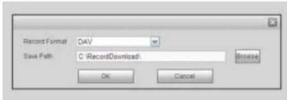
text_image
Record Format: DAV Save Path: C:\RecordDownload: Browse OK CancelFigure 5-125
You can click OK to download and view the download process. After the download operation, you can see corresponding dialog box.
- Download to USB
Connect the corresponding p peripheral device, and then click Download to USB button, you can see the following interface. See Figure 5-126.
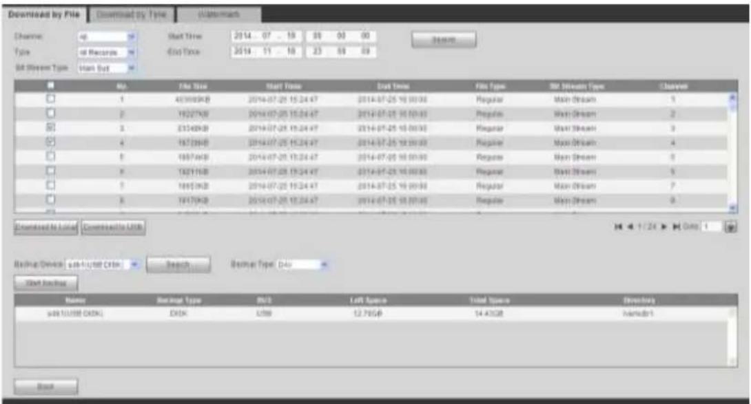
text_image
Downloaded by File Downloaded by Type Watermark Chancen: up Start Time 2014-07-25 19 30 00 00 Type: all Records 6box Time 2014-11-18 23 09 09 Bit Stream Type: Utah Out No. File Size Start Time Start Time File Type Bar Stream Type Change? 1 40100KB 2014-07-25 15:24:47 2014-07-25 15:00:00 Regular Main Stream 1 2 19227KB 2014-07-25 15:24:47 2014-07-25 15:00:00 Regular Main Stream 2 3 23340KB 2014-07-25 15:24:47 2014-07-25 15:00:00 Regular Main Stream 3 4 18728KB 2014-07-25 15:24:47 2014-07-25 15:00:00 Regular Main Stream 4 5 18974KB 2014-07-25 15:24:47 2014-07-25 15:00:00 Regular Main Stream 5 6 18211KB 2014-07-25 15:24:47 2014-07-25 15:00:00 Regular Main Stream 6 7 18953KB 2014-07-25 15:24:47 2014-07-25 15:00:00 Regular Main Stream 7 8 18479KB 2014-07-25 15:24:47 2014-07-25 15:00:00 Regular Main Stream 8 Downloaded by location Conversion to USB Basing Device sub-cycle order Search Basing Type Date Start Options Name Basing Type B/S Left Space Total Space Direction sub TCUSB EXBL EXK L3B 12.76GB 14.43GB Antebrt BookFigure 5-126
Select Backup device and backup type first and then click Start backup button.
After the download operation, you can see corresponding dialogue box.
5.10.5.2 Download by Time
Select channel, bit stream type, start time and end time.
Click Download to Local button, you can see download by time interface is shown as in Figure 5-127.
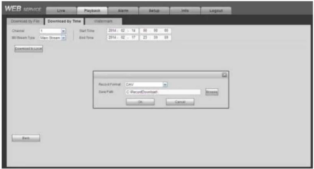
text_image
WEB SERVICE Live Playback Alarm Setup Units Layout Download by File Download by Time Watermark Channel 1 Start Time 2014 - 02 - 13 00 00 00 All Stream Time Main Stream Bed Time 2014 - 02 - 17 23 59 59 Download to Local Record Format: DAV Save Path: C:\RecordDownload\ Browse OK Cancel BackFigure 5-127
Set record format and saved path, you can click OK to download and view the download process. After the download operation, you can see corresponding dialog box.
5.10.5.3 Watermark
Watermark interface is shown as In Figure 5-128. Please select a file and then click Verify button to see the file has been tampered with or not
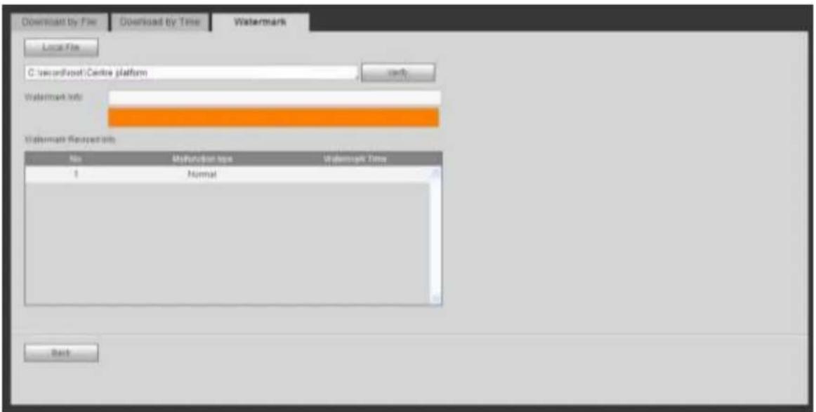
text_image
Download by File Download by Time Watermark Local File C:\secondFront/Centre platform Watermark info: Watermark Request info No Mifunction type Watermark Time 1 Normal BackFigure 5-128
5.11 Alarm
Click alarm function, you can see an interface is shown as Figure 5-129.
Here you can set device alarm type and alarm sound setup (Please make sure you have enabled audio function of corresponding alarm events.).
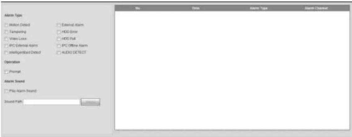
text_image
Alarm Type Motion Detected External Alarm Tampering HDD Enter Video Lock HDD Fail IPC External Alarm IPC Offline Alarm Intelligent/Ind Defect AUDIO DETECT Operation Prompt Alarm Sound Play Alarm Sound Sound PathFigure 5-129
Please refer to the following sheet for detailed information.
| Type | Parameter | Function |
| Alarm Type | Video loss | System alarms when video loss occurs. |
| Motion detection | System alarms when motion detection alarm occurs. | |
| Tampering | System alarms when camera is viciously masking. | |
| Disk full | System alarms when disk is full. | |
| Disk error | System alarms when disk error occurs. | |
| External alarm | Alarm input device sends out alarm. | |
| IPC external alarm | It refers to the on-off signal from the network camera. It can activate the NVR local activation operation. | |
| IPC offline alarm | System can generate an alarm when the network camera and the NVR are disconnected. | |
| Intelligent detect | System alarms when IVS alarm occurs. | |
| Audio detect | System alarms when audio detect is abnormal. | |
| Operation | Prompt | Check the box here, system can automatically pops up an alarm icon on the Alarm button in the main interface when there is an alarm. |
| Alarm Sound | Play alarm sound | System sends out alarm sound when an alarm occurs. You can specify as you wish. |
| Sound path | Here you can specify alarm sound file. |
5.12 Log out
Click log out button, system goes back to log in interface. See Figure 5-130.
You need to input user name and password to login again.
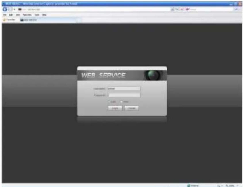
text_image
WEB SERVICE Password: 100% None 100% NoneFigure 5-130
5.13 Un-install Web Control
You can use web un-install tool "uninstall web.bat" to un-install web control.
Please note, before you un-installation, please close all web pages, otherwise the un-installation might result in error
6 Glossary
- DHCP: DHCP (Dynamic Host Configuration Protocol) is a network protocol. It is one of the TCP/IP protocol cluster. It is principally used to assign temporary IP addresses to computers on a network.
- DDNS: DDNS (Dynamic Domain Name Server) is a service that maps Internet domain names to IP addresses. This service is useful to anyone who wants to operate a server (web server, mail server, ftp server and etc) connected to the internet with a dynamic IP or to someone who wants to connect to an office computer or server from a remote location with software.
- eSATA: eSATA(External Serial AT) is an interface that provides fast data transfer for external storage devices. It is the extension specifications of a SATA interface.
● GPS: GPS (Global Positioning System) is a satellite system, protected by the US military, safely orbiting thousands of kilometers above the earth.
- PPPoE: PPPoE (Point to Point Protocol over Ethernet) is a specification for connecting multiple computer users on an Ethernet local area network to a remote site. Now the popular mode is ADSL and it adopts PPPoE protocol.
- WIFI: Wi-Fi is the name of a popular wireless networking technology that uses radio waves to provide wireless high-speed Internet and network connections. The standard is for wireless local area networks (WLANs). It is like a common language that all the devices use to communicate to each other. It is actually IEEE802.11, a family of standard The IEEE (Institute of Electrical and Electronics Engineers Inc.)
- 3G: 3G is the wireless network standard. It is called 3G because it is the third generation of cellular telecom standards. 3G is a faster network for phone and data transmission and speed Is over several hundred kbps. Now there are four standards: CDMA2000, WCDMA, TD-SCDMA and WiMAX.
- Dual-stream: The dual-stream technology adopts high-rate bit stream for local HD storage such as QCIF/CIF/2CIF/DCIF/4CIF encode and one low-rate bit stream for network transmission such as QCIF/CIF encode. It can balance the local storage and remote network transmission. The dual-stream can meet the difference band width requirements of the local transmission and the remote transmission. In this way, the local transmission using high-bit stream can achieve HD storage and the network transmission adopting low bit stream suitable for the fluency requirements of the 3G network such as WCDMA, EVDO, TD-SCDMA.
- On-off value: It is the non-consecutive signal sampling and output. It includes remote sampling and remote output. It has two statuses: 1/0.
7 FAQ
| Questions | Solutions |
| NVR can not boot up properly. | Input power is not correct.Power connection is not correct.Power switch button is damaged.Program upgrade is wrong.HDD malfunction or something wrong with HDD ribbon.Seagate DB35.1, DB35.2, SV35 or Maxtor 17-g has compatibility problem. Please upgrade to the latest version to solve this problem.Front panel error.Main board is damaged. |
| NVR often automatically shuts down or stops running. | Input voltage is not stable or it is too low.HDD malfunction or something wrong with the ribbon.Button power is not enough.Front video signal is not stable.Working environment is too harsh, too much dust.Hardware malfunction. |
| System can not detect hard disk. | HDD is broken.HDD ribbon is damaged.HDD cable connection is loose.Main board SATA port is broken. |
| There is no video output whether it is one-channel, multiple-channel or all-channel output. | Program is not compatible. Please upgrade to the latest version.Brightness is 0. Please restore factory default setup.Check your screen saver.NVR hardware malfunctions. |
| I can not search local records. | HDD ribbon is damaged.HDD is broken.Upgraded program is not compatible.The recorded file has been overwritten.Record function has been disabled. |
| Video is distorted when searching local records. | Video quality setup is too low.Program read error, bit data is too small. There is mosaic in the full screen. Please restart the NVR to solve this problem.HDD data ribbon error.HDD malfunction.NVR hardware malfunctions. |
| Time display is not correct. | Setup is not correctBattery contact is not correct or voltage is too low.Crystal is broken. |
| NVR can not control PTZ. | ● Front panel PTZ error● PTZ decoder setup, connection or installation is not correct.● Cable connection is not correct.● PTZ setup is not correct.● PTZ decoder and NVR protocol is not compatible.● PTZ decoder and NVR address is not compatible.● When there are several decoders, please add 120 Ohm between the PTZ decoder A/B cables furthest end to delete the reverberation or impedance matching. Otherwise the PTZ control is not stable.● The distance is too far. |
| I can not log in client-end or web. | ● For Windows 98 or Windows ME user, please update your system to Windows 2000 sp4. Or you can install client-end software of lower version. Please note right now, our NVR is not compatible with Windows VISTA control.● ActiveX control has been disabled.● No dx8.1 or higher. Please upgrade display card driver.● Network connection error.● Network setup error.● Password or user name is invalid.● Client-end is not compatible with NVR program. |
| There is only mosaic no video when preview or playback video file remotely. | ● Network fluency is not good.● Client-end resources are limit.● Current user has no right to monitor. |
| Network connection is not stable. | ● Network is not stable.● IP address conflict.● MAC address conflict.● PC or device network card is not good. |
| Burn error /USB back error. | ● Burner and NVR are in the same data cable.● System uses too much CPU resources. Please stop record first and then begin backup.● Data amount exceeds backup device capacity. It may result in burner error.● Backup device is not compatible.● Backup device is damaged. |
| Keyboard can not control NVR. | ● NVR serial port setup is not correct● Address is not correct● When there are several switchers, power supply is not enough.● Transmission distance is too far. |
| Alarm signal can not been disarmed. | ● Alarm setup is not correct.● Alarm output has been open manually.● Input device error or connection is not correct.● Some program versions may have this problem. Please upgrade your system. |
| Alarm function is null. | ● Alarm setup is not correct.● Alarm cable connection is not correct.● Alarm input signal is not correct.● There are two loops connect to one alarm device. |
| Record storage period is not enough. | ● Camera quality is too low. Lens is dirty. Camera is installed against the light. Camera aperture setup is not correct.● HDD capacity is not enough.● HDD is damaged. |
| Can not playback the downloaded file. | ● There is no media player.● No DXB8.1 or higher graphic acceleration software.● There is no DivX503Bundle.exe control when you play the file transformed to AVI via media player.● No DivX503Bundle.exe or ffdshow-2004 1012 .exe in Windows XP OS. |
| Forgot local menu operation password or network password | ● Please contact your local service engineer or our sales person for help. We can guide you to solve this problem. |
| There is no video. The screen is in black. | ● IPC IP address is not right.● IPC port number is not right.● IPC account (user name/password) is not right.● IPC is offline. |
| The displayed video is not full in the monitor. | Please cheek current resolution setup. If the current setup is 1920*1080, then you need to set the monitor resolution as 1920*1080. |
| There is no HDMI output. | ● Displayer is not in HDMI mode.● HDMI cable connection is not right. |
| The video is not fluent when I view in multiple-channel mode from the client-end. | ● The network bandwidth is not sufficient. The multiple-channel monitor operation needs at least 100M or higher.● Your PC resources are not sufficient. For 16-ch remote monitor operation, the PC shall have the following environment:Quad Core, 2G or higher memory, independent displayer, display card memory 256M or higher. |
| I can not connect to the IPC | Please make sure the IPC has booted up.IPC network connection is right and it is onlineIPC IP is in the blacklist.The device has connected to the too many IPC. It can not transmit the video.Check the IPC port value and the time zone is the same as the NVR.Make sure current network environment is stable. |
| After I set the NVR resolution as 1080P, my monitor can not display. | Shut down the device and then reboot. When you reboot, please press the Fn button at the same time and then release after 5 seconds. You can restore NVR resolution to the default setup. |
| My admin account has been changed and I can not log in. | Use telnet and then input the following command:cd /mnt/mtd/Config/rm -rf grouprm -rf passwordReboot the device to restore the default password. |
| After I login the Web , I can not find the remote interface to add the IPC. | Please clear the Web controls and load again. |
| There is IP and gateway, I can access the internet via the router. But I can not access the internet after I reboot the NVR. | Please use command PING to check you can connect to the gateway or not. Use telnet to access and then use command “ifconfig -a” to check device IP address. If you see the subnet mask and the gateway has changed after the reboot. Please upgrade the applications and set again. |
| I use the VGA monitor.I want to know if I use the multiple-window mode, I see the video from the main stream or the sub stream? | For 32-channel series product, the 9/16-window is using the sub stream.For 4/8/16 series product, system is using the main stream no matter you are in what display mode. |
Daily Maintenance
- Please use the brush to clean the board, socket connector and the chassis regularly.
- The device shall be soundly earthed in case there is audio/video disturbance. Keep the device away from the static voltage or induced voltage.
- Please unplug the power cable before you remove the audio/video signal cable, RS232 or RS485 cable.
- Do not connect the TV to the local video output port (VOUT). It may result in video output circuit.
● Always shut down the device properly. Please use the shutdown function in the menu, or you can press the power button in the rear pane for at least three seconds to shut down the device.
Otherwise it may result in HDD malfunction.
- Please make sure the device is away from the direct sunlight or other heating sources. Please keep the sound ventilation.
- Please check and maintain the device regularly.
8 Appendix A HDD Capacity Calculation
Calculate total capacity needed by each device according to video recording (video recording type and video file storage time).
Step 1: According to Formula (1) to calculate storage capacity q_i that is the capacity of each channel needed for each hour, unit Mbyte.
$$ q _ {i} \quad d _ {i} \quad 1 0 2 4. \tag {1} $$
In the formula d_i means the bit rate, unit Kbit/s
Step 2: After video time requirement is confirmed, according to Formula (2) to calculate the storage capacity m_i , which is storage of each channel needed unit Mbyte.
$$ m _ {i} = q _ {i} \times h _ {i} \times D _ {i} \tag {2} $$
In the formula:
h_i means the recording time for each day (hour)
D_i means number of days for which the video shall be kept
Step 3: According to Formula (3) to calculate total capacity (accumulation) q_T that is needed for all channels in the device during scheduled video recording.
$$ q _ {T} = \sum_ {i = 1} ^ {c} m _ {i} \tag {3} $$
In the formula: c means total number of channels in one device
Step 4: According to Formula (4) to calculate total capacity (accumulation) q_T that is needed for all channels in device during alarm video recording (including motion detection).
$$ q _ {T} = \sum_ {i = 1} ^ {c} m _ {i} \times a \% \tag{4} $$
In the formula: a% means alarm occurrence rate
9 Appendix B Compatible Network Camera List
Please note all the models in the following list for reference only. For those products not included in the list, please contact your local retailer or technical supporting engineer for detailed information.
| Manufacture | Model | Version | Video Encode | Audio/Video | Protocol |
| AXIS | P1346 | 5.40.9.2 | H264 | √ | ONVIF/Private |
| P3344/P3344-E | 5.40.9.2 | H264 | √ | ONVIF/Private | |
| P5512 | — | H264 | √ | ONVIF/Private | |
| Q1604 | 5.40.3.2 | H264 | √ | ONVIF/Private | |
| Q1604-E | 5.40.9 | H264 | √ | ONVIF/Private | |
| Q6034E | — | H264 | √ | ONVIF/Private | |
| Q6035 | 5.40.9 | H264 | √ | ONVIF/Private | |
| Q1755 | — | H264 | √ | ONVIF/Private | |
| M7001 | — | H264 | √ | Private | |
| M3204 | 5.40.9.2 | H264 | √ | Private | |
| P3367 | HEAD LFP4_0 130220 | H264 | √ | ONVIF | |
| P5532-P | HEAD LFP4_0 130220 | H264 | √ | ONVIF | |
| ACTi | ACM-3511 | A1D-220-V3.12 .15-AC | MPEG4 | √ | Private |
| ACM-8221 | A1D-220-V3.13 .16-AC | MPEG4 | √ | Private | |
| Arecont | AV1115 | 65246 | H264 | √ | Private |
| AV10005DN | 65197 | H264 | √ | Private | |
| AV2115DN | 65246 | H264 | √ | Private | |
| AV2515DN | 65199 | H264 | √ | Private | |
| AV2815 | 65197 | H264 | √ | Private | |
| AV5115DN | 65246 | H264 | √ | Private | |
| AV8185DN | 65197 | H264 | √ | Private | |
| Bosch | NBN-921-P | — | H264 | √ | ONVIF |
| NBC-455-12P | — | H264 | √ | ONVIF | |
| VG5-825 | 9500453 | H264 | √ | ONVIF | |
| NBN-832 | 66500500 | H264 | √ | ONVIF | |
| VEZ-211-IWT EIVA | — | H264 | √ | ONVIF | |
| NBC-255-P | 15500152 | H264 | √ | ONVIF | |
| VIP-X1XF | — | H264 | √ | ONVIF | |
| Brikcom | B0100 | — | H264 | √ | ONVIF |
| D100 | — | H264 | √ | ONVIF | |
| GE-100-CB | — | H264 | √ | ONVIF | |
| FB-100A | v1.0.3.9 | H264 | √ | ONVIF | |
| FD-100A | v1.0.3.3 | H264 | √ | ONVIF | |
| Cannon | VB-M400 | — | H264 | √ | Private |
| CNB | MPix2.0DIR | XNETM112011 1229 | H264 | √ | ONVIF |
| VIPBL1.3MIR VF | XNETM210011 1229 | H264 | √ | ONVIF | |
| IGC-2050F | XNETM210011 1229 | H264 | √ | ONVIF | |
| CP PLUS | CP-NC9-K | 6.E.2.7776 | H264 | √ | ONVIF/Private |
| CP-NC9W-K | 6.E.2.7776 | H264 | √ | Private | |
| CP-ND10-R | cp20111129AN S | H264 | √ | ONVIF | |
| CP-ND20-R | cp20111129AN S | H264 | √ | ONVIF | |
| CP-NS12W-C R | cp20110808NS | H264 | √ | ONVIF | |
| VS201 | cp20111129NS | H264 | √ | ONVIF | |
| CP-NB20-R | cp20110808BN S | H264 | √ | ONVIF | |
| CP-NT20VL3-R | cp20110808BN S | H264 | √ | ONVIF | |
| CP-NS36W-A R | cp20110808NS | H264 | √ | ONVIF | |
| CP-ND20VL2-R | cp20110808BN S | H264 | √ | ONVIF | |
| CP-RNP-1820 | cp20120821NS A | H264 | √ | Private | |
| CP-RNC-TP2 0FL3C | cp20120821NS A | H264 | √ | Private | |
| CP-RNP-12D | cp20120828AN S | H264 | √ | Private | |
| CP-RNC-DV1 0 | cp20120821NS A | H264 | √ | Private | |
| CP-RNC-DP2 0FL2C | cp20120821NS A | H264 | √ | Private | |
| Dynacolor | ICS-13 | d20120214NS | H264 | √ | ONVIF/Private |
| ICS-20W | vt20111123NSA | H264 | √ | ONVIF/Private | |
| NA222 | — | H264 | √ | ONVIF | |
| MPC-IPVD-03 13 | k20111208ANS | H264 | √ | ONVIF/Private | |
| MPC-IPVD-03 13AF | k20111208BNS | H264 | √ | ONVIF/Private | |
| Honeywell | HIDC-1100PT | h.2.2.1824 | H264 | √ | ONVIF |
| HIDC-1100P | h.2.2.1824 | H264 | √ | ONVIF | |
| HIDC-0100P | h.2.2.1824 | H264 | √ | ONVIF | |
| HIDC-1300V | 2.0.0.21 | H264 | √ | ONVIF | |
| HICC-1300W | 2.0.1.7 | H264 | √ | ONVIF | |
| HICC-2300 | 2.0.0.21 | H264 | √ | ONVIF | |
| HDZ20HDX | H20130114NSA | H264 | √ | ONVIF | |
| LG | LW342-FP | — | H264 | √ | Private |
| LNB5100 | — | H264 | √ | ONVIF | |
| Imatek | KNC-B5000 | — | H264 | √ | Private |
| KNC-B5162 | — | H264 | √ | Private | |
| KNC-B2161 | — | H264 | √ | Private | |
| Panasonic | NP240/CH | — | MPEG4 | √ | Private |
| WV-NP502 | — | MPEG4 | √ | Private | |
| WV-SP102H | 1.41 | H264 | √ | ONVIF/Private | |
| WV-SP105H | — | H264 | √ | ONVIF/Private | |
| WV-SP302H | 1.41 | H264、MPEG4 | √ | ONVIF/Private | |
| WV-SP306H | 1.4 | H264、MPEG4 | √ | ONVIF/Private | |
| WV-SP508H | — | H264、MPEG4 | √ | ONVIF/Private | |
| WV-SP509H | — | H264、MPEG4 | √ | ONVIF/Private | |
| WV-SF332H | 1.41 | H264、MPEG4 | √ | ONVIF/Private | |
| WV-SW316H | 1.41 | H264、MPEG4 | √ | ONVIF/Private | |
| WV-SW355H | 1.41 | H264、MPEG4 | √ | ONVIF/Private | |
| WV-SW352H | — | H264、MPEG4 | √ | ONVIF/Private | |
| WV-SW152E | 1.03 | H264、MPEG4 | √ | ONVIF/Private | |
| WV-SW558H | — | H264、MPEG4 | √ | ONVIF/Private | |
| WV-SW559H | — | H264、MPEG4 | √ | ONVIF/Private | |
| WV-SP105H | 1.03 | H264、MPEG4 | √ | ONVIF/Private | |
| WV-SW155E | 1.03 | H264、MPEG4 | √ | ONVIF/Private | |
| WV-SF336H | 1.44 | H264、MPEG4 | √ | ONVIF/Private | |
| WV-SF332H | 1.41 | H264、MPEG4 | √ | ONVIF/Private | |
| WV-SF132E | 1.03 | H264、MPEG4 | √ | ONVIF/Private | |
| WV-SF135E | 1.03 | H264、MPEG4 | √ | ONVIF/Private | |
| WV-SF346H | 1.41 | H264、MPEG4 | √ | ONVIF/Private | |
| WV-SF342H | 1.41 | H264、MPEG4 | √ | ONVIF/Private | |
| WV-SC385H | 1.08 | H264、MPEG4 | √ | ONVIF/Private | |
| WV-SC386H | 1.08 | H264、MPEG4 | √ | ONVIF/Private | |
| WV-SP539 | 1.66 | H264、MPEG4 | √ | ONVIF | |
| DG-SC385 | 1.66 | H264、MPEG4 | √ | ONVIF | |
| PELCO | IXSOLW | 1.8.1-20110912-1.9082-A1.6617 | H264 | √ | Private |
| IDE20DN | 1.7.41.9111-O3.6725 | H264 | √ | Private | |
| D5118 | 1.7.8.9310-A1.5288 | H264 | √ | Private | |
| IM10C10 | 1.6.13.9261-O2.4657 | H264 | √ | Private | |
| DD4N-X | 01.02.0015 | MPEG4 | √ | Private | |
| DD423-X | 01.02.0006 | MPEG4 | √ | Private | |
| D5220 | 1.8.3-FC2-20120614-1.9320-A1.8035 | H264 | √ | Private | |
| Samsung | SNB-3000P | 2.41 | H264、MPEG4 | √ | ONVIF/Private |
| SNP-3120 | 1.22_110120_1 | H264、MPEG4 | √ | ONVIF/Private | |
| SNP-3370 | 1.21_110318 | MPEG4 | √ | Private | |
| SNB-5000 | 2.10_111227 | H264、MPEG4 | √ | ONVIF/Private | |
| SND-5080 | — | H264、MPEG4 | √ | Private | |
| SNZ-5200 | 1.02_110512 | H264、MPEG4 | √ | ONVIF/Private | |
| SNP-5200 | 1.04_110825 | H264、MPEG4 | √ | ONVIF/Private | |
| SNB-7000 | 1.10_110819 | H264 | √ | ONVIF/Private | |
| SNB-6004 | V1.0.0 | H264 | √ | ONVIF | |
| Sony | SNC-DH110 | 1.50.00 | H264 | √ | ONVIF/Private |
| SNC-CH120 | 1.50.00 | H264 | √ | ONVIF/Private | |
| SNC-CH135 | 1.73.01 | H264 | √ | ONVIF/Private | |
| SNC-CH140 | 1.50.00 | H264 | √ | ONVIF/Private | |
| SNC-CH210 | 1.73.00 | H264 | √ | ONVIF/Private | |
| SNC-DH210 | 1.73.00 | H264 | √ | ONVIF/Private | |
| SNC-DH240 | 1.50.00 | H264 | √ | ONVIF/Private | |
| SNC-DH240-T | 1.73.01 | H264 | √ | ONVIF/Private | |
| SNC-CH260 | 1.74.01 | H264 | √ | ONVIF/Private | |
| SNC-CH280 | 1.73.01 | H264 | √ | ONVIF/Private | |
| SNC-RH-124 | 1.73.00 | H264 | √ | ONVIF/Private | |
| SNC-RS46P | 1.73.00 | H264 | √ | ONVIF/Private | |
| SNC-ER550 | 1.74.01 | H264 | √ | ONVIF/Private | |
| SNC-ER580 | 1.74.01 | H264 | √ | ONVIF/Private | |
| SNC-ER580 | 1.78.00 | H264 | √ | ONVIF | |
| SNC-VM631 | 1.4.0 | H264 | √ | ONVIF | |
| WV-SP306 | 1.61.00 | H264、MPEG4 | √ | SDK | |
| WV-SP306 | 1.61.00 | H264 | √ | ONVIF | |
| SNC-VB600 | 1.5.0 | H264 | √ | Private | |
| SNC-VM600 | 1.5.0 | H264 | √ | Private | |
| SNC-VB630 | 1.5.0 | H264 | √ | Private | |
| SNC-VM630 | 1.5.0 | H264 | √ | Private | |
| SANYO | VCC-HDN4000PC | — | H264 | √ | ONVIF |
Note
• This manual is for reference only. Slight difference may be found in the user interface.
• All the designs and software here are subject to change without prior written notice.
• All trademarks and registered trademarks are the properties of their respective owners.
• If there is any uncertainty or controversy, please refer to the final explanation of us.
- Please visit our website or contact your local service engineer for more information.
Dahua Technology Co., Ltd
Address: No.1199 Bin'an Road, Binjiang District, Hangzhou, China.
Postcode: 310053
Tel: +86-571-87688883
Fax: +86-571-87688815
Email:overseas@dahuatech.com
Website: www.dahuatech.com