RA10 - Car stereo DLS - Free user manual and instructions
Find the device manual for free RA10 DLS in PDF.


User questions about RA10 DLS
0 question about this device. Answer the ones you know or ask your own.
Ask a new question about this device
Download the instructions for your Car stereo in PDF format for free! Find your manual RA10 - DLS and take your electronic device back in hand. On this page are published all the documents necessary for the use of your device. RA10 by DLS.
USER MANUAL RA10 DLS
How to install and operate the DLS Reference series car audio mono amplifier RA10.
Welcome!
This owners manual is written in easy english and uses a lot of drawings to simply the installation and use of the above amplifiers.
Your DLS amplifiers must be installed correctly in order to work well. This manual will show you how to install the amplifier like a pro. Please read the entire manual before beginning the installation. Install the amplifier yourself if you feel confident with our instructions and if you have the proper tools. However if you feel unsure, turn over the installation job to someone better suited to it.
Warranty Service
This amplifier is covered by warranty, depending on the conditions in the country where it is sold. If the amplifier is returned for service, please include the original dated receipt with the product.

Technical Assistance
For technical assistance ask the shop where the product was sold or the distributor in your very country.
You can always phone the DLS Helpdesk in Sweden + 46 31 84 00 60 or send an e-mail to info@dls.se. Information can also be found on our WEB-site www.dls.se
Contents
Features......2
Installation....2
Tools and materials needed...... 3
Amplifier installation kit.... 3
Routing Wires.... 3
Wiring:
Power connection.... 4
Input and controls.... 5
Input wiring....5
Input level control....6
Grand Bass....6
Phase control....6
Crossovers......6
RA10 speaker wiring:
One subwoofer....7
Two subwoofers....7
Four subwoofers....7
Installation with two subwoofers:
Wiring example....8
Testing....9
Troubleshooting....9
Professional tips.... 10
Specifications.... 11
The amplifier include
- RCA inputs
- High Level input
- Variable low pass crossover
Subsonic filter - Grand bass feature 0 - +18 dB
- Phase shift continuously variable 0-180 degr.
◆ Remote bass level and phase shift control - Remote turn on / off
- Automatic remote turn on/off on high level input without connecting any remote wire
Built-in cooling fan
Electronic protection circuitry against short-circuit, DC offset and thermal overload.
Installation
Before you begin installation
Before you begin you need to read the manual, to have some tools, cables and other material available. There is one such list of material on the following page.
Amplifier location
Important
Allow air circulation around the amplifier.
The DLS Reference series of amplifiers have a compact design that allows great flexibility in mounting. You can mount it under a seat or in the trunk. When you select a location, do remember that the amplifier generates a lot of heat.
Choose a location where air can circulate freely around the amplifier. Do not cover the amplifier with carpets or hide behind trim panels.
Do not mount the amplifier in an inverted or upside down position. The amplifier has a built-in fan in the bottom plate. Mount the amplifier on spacers to allow the air to circulate inside the amplifier.
Check all locations and placements carefully before making any cuts, drilling any holes or making any connections.
This is the best direction to mount the amplifier in order to get the best cooling.

Disconnect Battery
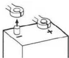
Before starting the installation, always disconnect the negative terminal of the battery.
natural_image
Simple line drawing of a hand using a ring to lift a cylindrical object on a table, with no text or symbols present.DLS logo on amplifier cooling flange
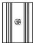
The DLS logo on top of the amplifier is attached with two hex. screws. The logo can be removed and twisted 90 or 180 degrees, and then screwed back in wanted position. The logo can be mounted in four different ways to match your installation.



Tools and material needed
Tools:
◆ Flat and Phillips screwdrivers
Wire cutter
- Wire stripper
- Electric drill with drills
- Crimping tool
◆ Digital multimeter or test lamp
◆ Wire brush, scraper or a piece of an abrasive sheet to remove paint for a good ground connection
- Grease to protect the ground connection from oxidation
Material:
- Speaker wire: minimum 12 AWG = 4 mm² for subwoofer connection
- Sheet metal screws for mounting the amplifier to the amplifier board and the amplifier board to the car + some extra for fuse holder, amplifier ground etc.
Electrical insulation tape - 12 inch thick plywood or particle board for the amplifier to be mounted upon.
Amplifier installation kit:
If available, buy an amplifier installation kit. It contains normally all you need. This is what you have to buy if you buy the items separately
20- 25 feet = 6- 7.5 meter power cable, 4 AWG = 21 mm² or heavier.
- 1 pc of fuseholder to install close to the car battery + fuse 100 Ampere (for 4AWG power cable).
- 20 feet of 15 AWG = 1,5 mm ^2 wire for remote turn on / off cable from radio.
♦ RCA-cable for input from radio.
- 20 feet or 5 meter for trunk installations
-12 feet or 2 – 3 meter for under seat installations
- Two ring crimp terminals—one for connection to the battery plus and one for the amplifier ground connection.
- Four splicers to connect speaker cables to high level input cable, if high level input is used.
- Wire ties
- Insulating grommet or insulating tube
Professional Tip:
If amplifier installation kits are available with different size of power cable, chose the most heavy power cable to improve sound quality and to allow more amplifiers to be installed now or later.
If possible use 4 AWG = 21 mm ^2 cable for best performance. This is for cable lengths up to 5 meters. The ground cable must have the same size.
Max fuse values for different cable sizes:
| 6 mm ^2 (9 AWG) :25 A 10 mm | ^2 (7AWG) :40 A |
| 16 mm ^2 (5AWG) :60 A 21 mm | ^2 (4AWG) :100 A |
| 33 mm ^2 (2AWG) :150 A 42 mm | ^2 (1AWG) :200 A |
Routing wires
text_image
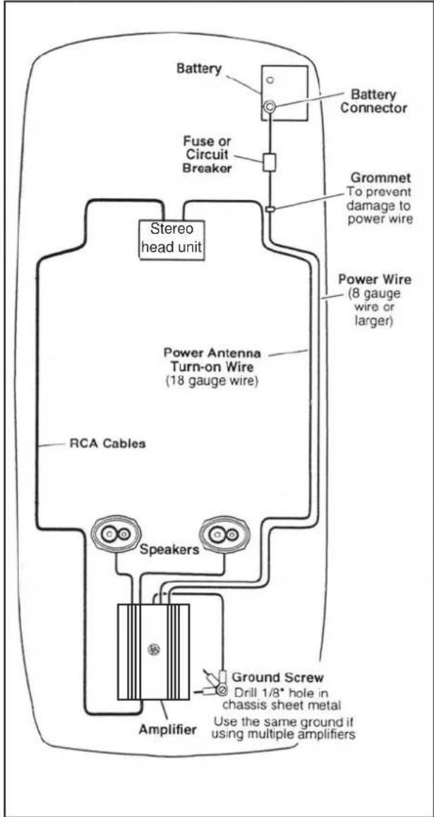
Battery Battery Connector Fuse or Circuit Breaker Grommet To prevent damage to power wire Stereo head unit Power Antenna Turn-on Wire (18 gauge wire) RCA Cables Speakers Amplifier Ground Screw Drill 1/8" hole in chassis sheet metal Use the same ground if using multiple amplifiersProfessional Tip:
Gauge (ga) is an American measure for cable size, also called AWG (American Wire Gauge).
CONVERSION GAUGE - mm²
0 AWG = 50 mm²
1 AWG = 42 mm² 9 AWG = 6.8 mm²
2 AWG = 33 mm² 10 AWG = 5,3 mm²
3 AWG = 27 mm² 11 AWG = 4,2 mm²
4 AWG = 21 mm² 12 AWG = 3 mm²
5 AWG = 16 mm² 13 AWG = 2.7 mm²
6 AWG = 13 mm² 14 AWG = 2 mm²
7 AWG = 10 mm² 15 AWG = 1,65 mm²
8 AWG = 8 mm² 16 AWG = 1,3 mm²
Wiring
Power connections
Power terminal (+12V)
Connect the fuse holder as close to the vehicle battery + as possible, using 4 AWG = 21 mm² or heavier cable. Use ring crimp terminal cable to connect to battery +. Apply silicon grease to the fuse to prevent corrosion.
Use a 100 Amp fuse for cable
4 AWG (21 mm²).
RA10 accepts 4 AWG (21 mm ^4 ) in the power terminal.

text_image
AWG (21 mmF). A10 accepts 4 AWG (21 mm²) in the power terminal. Connect with ring terminal to battery + terminal DLS DLS FH2B fuse holder GND REMOTE BATT+Connect the battery cable from the fuse holder to the +12 Volt terminal on the amplifier.
Be sure to use a rubber grommet or a plastic insulating tube where the cable passes the firewall or other places when it can easily be jammed.
Use ty-wraps to secure to existing cables in the engine compartment.
Ground Terminal ( GND )
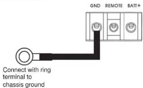
Connect to a good chassis ground. The ground connection should be clean, unpainted metal to provide a good electrical connection. Use a wire brush, a scraper or a piece of an abrasive sheet to clean the metal. Use a lock washer or two to secure contact. Protect with silicon grease or by paint applied afterwards.
text_image
GND REMOTE BATT+ Connect with ring terminal to chassis groundFuses on amplifier
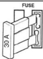
Use only four 30 ampere ATC blade type fuses.
Remote terminal ( REM )
For RCA cable signal input:
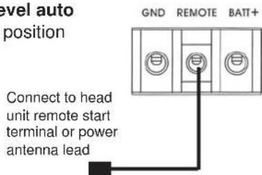
Set the input selector switch to position "Low level". Connect the radio power antenna lead = remote turn on/off from the car stereo to the amplifier remote connection. This turns on the amplifier whenever the car stereo is turned on.
You can either use the built in remote cable in the RCA cable itself or use a separate cable.
Sometimes a small disturbance may enter the amplifier coming from the remote voltage, through the built in remote wire and into the RCA cable. Thus we recommend to use a separate remote wire and run the RCA lead separate from remote wire, power cables and speaker cables.
Insert the cable directly into the amplifier terminal. If there is no remote voltage available from the stereo, you must connect to the ignition key through the radio or any accessories fuse.
Set the "High level auto start" switch to position OUT.
text_image
level auto position GND REMOTE BATT+ Connect to head unit remote start terminal or power antenna leadFor High Level input:
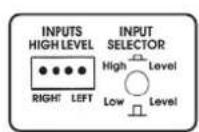
Set the input selector switch to position "High level". We recommend you to connect the remote wire as described above. The amplifier will produce soft on / soft off operation this way. If you use a remote wire, set the switch "High level auto start" to position OUT.
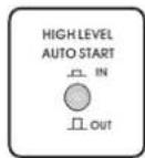
In the case that there is no remote voltage available from the car stereo, or you want to simplify the installation, the amplifier can be turned on/ turned off by the high level input voltage. This is done when the "High level auto start" switch is set to IN - position.
Power Light / Protect light
Power
(Green)


Protect
(Red)
The power light (green) comes on when the amplifier is turned on.
The protect light (red) comes on when the amplifier shuts down from overheating, DC-offset or a short circuit (speaker failure)
text_image
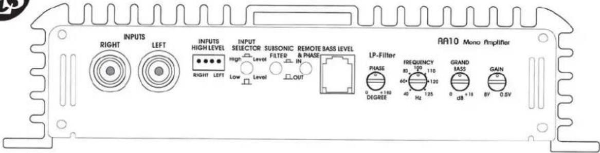
INPUTS RIGHT LEFT INPUTS HIGH LEVEL INPUT SELECTOR HIGH LEVEL SUBSONIC FILTER LOW LEVEL REMOTE BASS LEVEL & PHASE LP-Filter PHASE 0 +180 DEGREE FREQUENCY 80 100 110 60Hz 40 Hz 125 GRAND MASS 0 dB +18 GAIN 8V 0.5V AA10 Mono AmplifierInput Wiring
Inputs may be low level from the RCA output of the car stereo, or high level from the car stereo speaker output. Low level = RCA is to prefer for the best sound quality.
Low level input
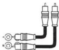
Use a pair of shielded stereo audio cables with RCA type jack. Most trunk-mount amplifiers need a 20 feet RCA cable (appr 5–6 meters). Most under the seat installations require 12 feet (2–3 meters) RCA cables. Avoid placing the RCA cable close to speaker cables, power cables and remote control cable. Connect to RCA input sockets. Both inputs must be connected. Use a Y-split if necessary.
Set the input selector switch to position "Low level".
High Level Input
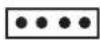
Connect left and right speaker wires coming from the car stereo to the high level input as shown. You must connect both plus and minus as the inputs are balanced, connecting plus only gives lower level and bad sound quality. By changing the polarity of plus and minus, you can change the phase.
High level input socket
Right Left
Hi level input
socket on amp.
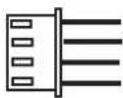
Hi level input plug.
Green: Left +
Black: Left
Black: Right -
Grey: Right +
Automatic turn on when using high level input.
With the "Input selector switch" set to High level and the "High level Auto Start" switch set to IN, the amplifier turns on automatically on high input. You don't need to connect a separate remote wire from your head unit.
If you want to use high level input but use a remote start wire, just set the "High level Auto Start" switch to OUT.
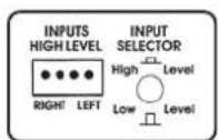
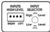
High / Low level input switch
To ensure best possible performance from the amplifier a switch is installed to select between High and Low input.
When using High Level input:
Push in the button to position "High Level"
When using Low level input:
Push out the button to position "Low Level"
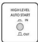
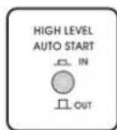
Hi level auto start switch
To ensure best possible performance from the amplifier when used with high level input a switch is installed to select between Automatic amplifier start and remote wire start.
When using High Level input with automatic start:
Push the button to position IN
When using High level input with remote wire start:
Push out the button to position OUT
NOTE!
Some head units use BTL output IC:s that have a constant 6-12 Volt + on the speaker terminal, also when shut off (the Power LED indicator lights constantly even when the head unit is off). In this case you have to use a separate remote wire connected to the REMOTE-terminal instead.

text_image
INPUTS RIGHT LEFT INPUTS HIGH LEVEL INPUT SELECTOR SUBSONIC FILTER REMOTE BASS LEVEL & PHASE LP-Filter PHASE FREQUENCY 80 100 110 40Hz 125 GRAND MASS 0 dB +18 GAIN 0.5V AA10 Mono AmplifierInput Level control
The input level control, 8V - 0.5 V, matches the output of your radio to the input of the amplifier. After installation is complete, make sure the input of the amplifier is turned down all the way ( counterclockwise at 8V ).
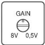
Play a tape or CD, make sure all bass or treble settings or equalizer are flat, and turn the volume of the radio up until you just start to hear distortion. Turn the volume control down just a bit. On the amplifier increase the input level control (clockwise or to the right) until you just start to hear distortion, then back the level control just a bit. Now your radio and amplifier levels are matched.
Grand bass 40 Hz
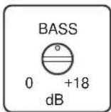
Grand Bass is used to increase the bass volume with a center frequency of 40 HZ. You can select the amplification between 0 dB (no amplification) and +18 dB (full amplification).
This function is used to compensate for the bass box function and to adjust for your own taste of bass. Set level control at 0 dB if you want it to be inoperative.
Phase control
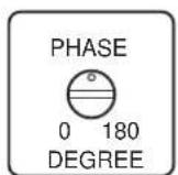
The phase control can be set continuously from 0 - 180 degrees. This is very useful when you want to adjust the bass sound for best front stage image. Start on 0 and turn the control slowly clockwise until you experience that the bass sound is coming from the front. If you dont get the result you want, also try to phase reverse the subwoofer connections and make a new adjustment. You can also adjust the phase from the front seat by using the Remote bass level and phase control box.
Crossovers
The DLS Reference amplifier RA10 include low pass filter (LP) and subsonic filter.
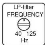
- LP-filter 40 - 125 Hz, slope 12 dB / octave
- Subsonic filter 25 Hz fixed frequency, slope 18 dB / octave. The subsonic filter can be switched off.
Low Pass Filter
The LP-filter (low pass filter) is used for subwoofers. It will allow low frequencies only and blocks higher frequencies. A typical setting is 50 – 80 Hz.
Subsonic filter
The subsonic filter is used to take away the very deepest frequencies from a bass box. The x-over frequency is 25 Hz.
Remote bass level and phase control box
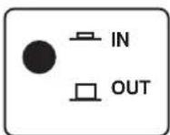
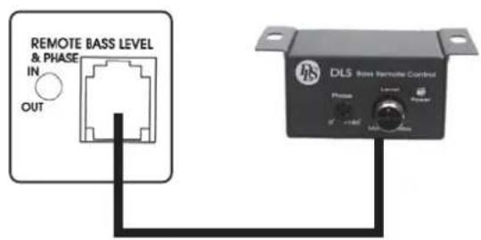
The amplifier includes a remote control unit. With this unit it is possible to adjust the bass level and phase from the front seat. Connect the cable between the amplifier socket and the socket on the remote box. Activate the remote control box by pushing the switch to position IN.
text_image
REMOTE BASS LEVEL & PHASE IN OUT DLS Boss Remote Control Phase Lamp Output 0 100kW 100kW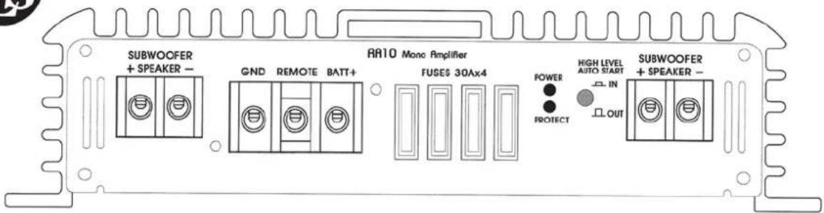
text_image
SUBWOOFER + SPEAKER - GND REMOTE BATT+ RA10 Monc Amplifier FUSES 30Ax4 POWER PROTECT HIGH LEVEL AUTO START IN OUT SUBWOOFER + SPEAKER -Speaker wiring RA10
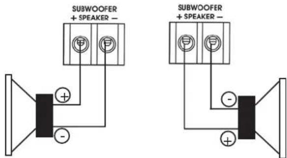
RA10 is a mono amplifier made for use with subwoofers only. The amplifier has two output connectors. These are internally connected in parallel and are doubled for easier connection when you have more than one subwoofer. It is not possible to connect in bridge mode between the speaker terminals.
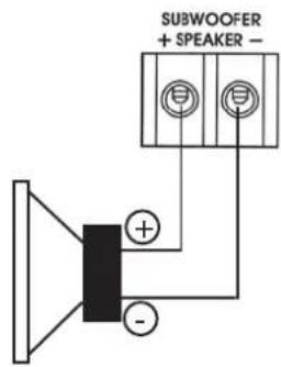
One 4 ohm subwoofer connected (4 ohm load)
text_image
SUBWOOFER + SPEAKER -Two 4 ohm subwoofers connected (2 ohm load)
text_image
SUBWOOFER + SPEAKER - SUBWOOFER + SPEAKER -LP-filter settings
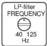
The typical setting is around 60 – 80 Hz.
The subsonic filter should be in position IN.
Four 4 ohm subwoofers connected (1 ohm load)

text_image
SUBWOOFER + SPEAKER - SUBWOOFER + SPEAKER -NOTE!
The amplifier is 1 ohm stable. This means that you can connect subwoofers in various connections, in parallel or in series, as long as the resulting impedance is not less than 1 ohm.
If you have subwoofers with dual 4 ohm voice coils, connect the coils in parallel to get more power from the amplifier.
Wiring example of RA 10 with two subwoofers
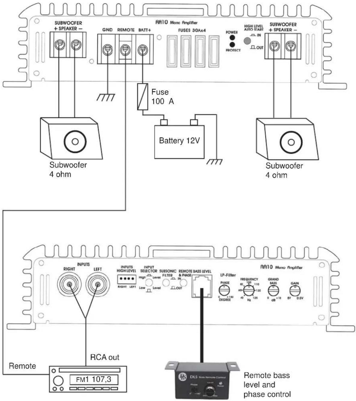
text_image
SUBWOOFER + SPEAKER - GND REMOTE BATT+ RR10 Mono Amplifier FUSES 30Ax4 HIGH LEVEL AUTO START IN POWER PROTECT SUBWOOFER + SPEAKER - Subwoofer 4 ohm Fuse 100 A Battery 12V Subwoofer 4 ohm INPUTS RIGHT LEFT INPUTS HIGH LEVEL INPUT SELECTOR High Level SUBSONIC FILTER & PHASE LEAVEL LEAVEL LEAVEL LEAVEL LEAVEL LEAVEL LEAVEL LEAVEL LEAVEL LEAVEL LEAVEL LEAVEL LEAVEL LEAVEL LEAVEL LEAVEL LEAVEL LEAVEL LEAVEL LEAVEL LEAVEL LEAVEL LEAVEL LEAVEL LEAVEL LEAVES LEAVES LEAVES LEAVES LEAVES LEAVES LEAVES LEAVES LEAVES LEAVES LEAVES LEAVES LEAVES LEAVES LEAVES LEAVES LEAVES LEAVES LEAVES LEAVES LEAVES LEAVES LEAVES LEAVES LEAVES LEAVes LEAVes LEAVes LEAVes LEAVes LEAVes LEAVes LEAVes LEAVes LEAVes LEAVes LEAVes LEAVes LEAVes LEAVes LEAVes LEAVes LEAVes LEAVes LEAVes LEAVes LEAVes LEAVes LEAVes LEAVes LEAVestles: FRUENCY 80 100 110 120 125 0 dB +19 8V 0.5V GRAND BASS 0 dB 19 0 dB 125 0 dB 125 0 dB 125 0 dB 125 0 dB 125 0 dB 125 0 dB 125 0 dB 125 0 dB 125 0 dB 125 0 dB 125 0 dB 125 0 dB 125 0 dB 125 0 dB 125 125 125 125 125 125 125 125 125 125 125 125 125 125 125 125 125 125 125 125 125 125 125 125 125 126 126 126 126 126 126 126 126 126 126 126 126 126 126 126 126 126 126 126 126 126 126 126 126 126 127 127 127 127 127 127 127 127 127 127 127 127 127 127 127 127 127 127 127 127 127 127 127 127 127 128 128 128 128 128 128 128 128 128 128 128 128 128 128 128 128 128 128 128 128 130.0000000000000000000000000000000000000000000000000000000000000000000000000000000000000000000000000000. Remote bass level and phase controlTesting
Before you finish the installation, you should do the following tests to make sure the wiring is correct and everything is operating properly.
Reconnect Battery
When wiring is complete, reconnect the battery negative terminal.
natural_image
Simple line drawing of two hands holding circular objects on a base, with no text or symbols present.Test power wiring
- Turn on the head unit but do not turn up the volume. The amplifier power light should come on. If not, check the remote and +12 volt wires. Also check the ground connection.
- Turn up the head units volume slightly. All speakers should operate. if not, check wiring connections at amplifier and speakers.
Test speaker connections
Make sure the speakers are connected right. Use the balance control on the head unit to make sure right channel is on right speaker etc. If speakers don't play at all, one or both speaker wires may be disconnected.
Troubleshooting
If problems occur during the installation, or later, this guide might help you to find out what's wrong.
THE AMPLIFIER IS DEAD:
- Check power lead, ground and remote connections at the amplifier using a multi meter.
- Check the battery terminal connections.
- Check the power lead fuse or circuit breaker. If fuse damage continues, inspect the power lead for short circuits.
- Check the amplifier protection fuses. Are these broken change to new ones with the same value. If short circuiting continues, contact your local DLS dealer. A fault may exist in the amplifier.
- To start the amplifier requires a remote voltage of 9-15 volt. Check the voltage with a multi meter.
AMPLIFIER PROTECTION FUSE BLOWS AT LOW VOLUME :
- One or more speaker cables are shorted. Make an insulation test with a multi meter. The cables must not have a connection to earth.
THE AMPLIFIER TURNS OFF AFTER 10 - 30 MINUTES.
The amplifier is overheating due to inadequate ventilation. Check mounting position is free from obstruction.
Do this:
- Move the amplifier to a place with better ventilation.
- Make sure the internal fan is working and that the amplifier is installed in a way that allows air to circulate freely inside the amplifier.
- Overheating can also be caused by an impedance load below the level permitted.
NO OUTPUT FROM ONE OR MORE SPEAKERS:
Check the following:
- Speaker cable connections to both amplifier and drivers.
- Signal lead plugs and cables.
NOISE PROBLEMS
WHINING NOISE VARYING WITH ENGINE REVOLUTIONS:
Do this:
- Rewire the power supply (12 V) to source unit direct from battery.
- Rewire ground wire from source unit to clean position on chassis.
- Check all power connections to ensure that they are clean and tight.
- Check quality of system ground connection.
- Install a Power Cap capacitor. This can be helpful against most noise problems.
CONSTANT WHINING NOISE:
Do this:
- Ensure that all equipment has a common ground point.
- Check quality of earth strap connection from battery negative terminal to chassis.
- Disconnect signal cables from amplifier to see if noise disappears. If so the leads are picking up noise. Test this by laying a new cable over the seats and reconnecting to the amplifier. If the noise does not return, re-route original cable away from source of interference. If noise remains regardless of cable position, try to use so called Quasi-balanced signal cables. DLS PRO-cables are Quasibalanced.
Professional Tip: Professional Tip:
Installing in trunk
When installing the amplifier in the trunk, run the power wires along the same path as the other vehicle wiring. Many cars have insulated channels for wiring. you will have to remove the door sill trim and the carpet.
Professional Tip:
Crimp connections
Purchase crimp connectors and crimping tool. Connectors are color coded.
- Strip 1/4 inch (6 mm) of insulation from the wire.
- Insert into connector
- Crimp tightly
Professional Tip: Professional Tip:
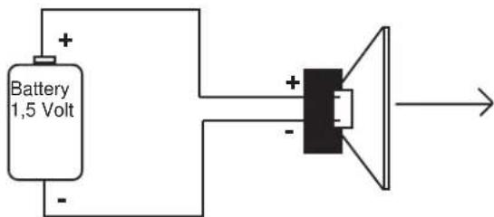
SPEAKER POLARITY CHECK.
All speakers in a car audio system should be connected in phase (the same polarity). All speaker cones must move in the same direction. Out of phase speakers will cause a lack of bass, and a poor stereo soundstage.
Checking polarity:
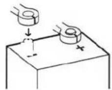
Hold the - connection of the speaker wire to the - terminal of a 1,5 Volt flashlight battery. Tap the + wire on to the + terminal of the battery, and observe the movement of the cone. The cone should move outwards when the wire touches the battery, and inwards when the battery is removed. If it is the other way around, the speaker has been connected backwards and it must be removed and connected correctly.
If your system also has a subwoofer connected through a passive 6 or 12 dB crossover, try to connect this with various polarity and judge what sounds best. The phase shift in passive crossovers sometimes makes it necessary to change polarity.
text_image
Battery 1,5 Volt + - + -NOTE! Tweeters can not be tested this way, double check the connections instead.
Securing wires
Use wire ties to bundle together when possible. (But never bundle speaker wires or signal cables together with power wires.

natural_image
Two types of wire or cable assemblies: a curved wire and a coiled bundle (no text or symbols)Professional Tip:
Speaker and power wires
Do not run speaker and power wires next to each other. Power wires can generate a "siren" sound in the speakers. Run speaker and power wires on opposite sides of the car.
DLS Reference RA10
Number of channels 1
Working mode AB
Power output at 13,8 Volt, max 0,1 % THD
Power output in 4 ohm 300 W
Power output in 2 ohm 500 W
Power output in 1 ohm 780 W
THD @1 W < 0,1%
Signal to noise ratio, A-weighted >100 dB
Damping factor >200
Frequency response +/- 3 dB 10 Hz - 125 Hz
Input impedance, low level >10 kohm
Input impedance, high level 330 ohm
High level input with auto start Yes
Input sensitivity 0,5 - 8V
Filter slope LP-filter 12 dB / octave
Filter slope subsonic filter 18 dB / octave
Pre amp configuration:
| Filter lowpass | 40 - 125 Hz |
| Fixed 25 Hz subsonic filter | Yes* |
| Phase shift 0- 180 degrees continuously | Yes |
| Grand bass adjustable gain @ 40 Hz | 0 - 18 dB |
| Remote bass level and phase control | Yes* |
| * can be switched in/out |
| Protection | current, DC-offset & thermal |
| Max cable size, DC input | 4 AWG, 21 mm^2 |
| Max cable size, speaker terminal 7 AWG, 10 mm | ^2 |
Power consumption:
| Idle | 0,6 A |
| Maximum | 120 A |
| Fuse | 4 x 30 A |
| Dimensions HxWxD(mm) | 59 x 359 x 245 |
| Dimensions (inch) | 2,33x14,13x9,65 |
| Weight | 4,3 kg(9,5 lbs) |
We follow a policy of continuous advancement in development.
For this reason all or part of specifications & designs may be changed without prior notice.

text_image
PSDLS Svenska AB
P.O. Box 13029