
E22 - Hi-Fi System LYNX - Free user manual and instructions
Find the device manual for free E22 LYNX in PDF.


| Product Type | Hi-Fi System |
| Brand | Lynx |
| Model | E22 |
| Dimensions (W x H x D) | Approx. 430 x 150 x 320 mm |
| Weight | Approx. 5.5 kg (main unit) |
| Power Supply | AC 230V ~ 50/60Hz |
| Power Consumption | 50W (typical), <1W standby |
| Supported Discs | CD, CD-R, CD-RW |
| Radio Bands | FM, AM |
| Audio Output Power | 2 x 30W RMS |
| Connectivity | USB, 3.5mm Aux-in, Bluetooth |
| Speaker Impedance | 4-8 Ohms |
| Remote Control | Included (batteries not supplied) |
| Display | LED digital display |
| Maintenance | Clean with soft dry cloth; avoid solvents |
| Safety | Do not expose to moisture; unplug during storms |
| Spare Parts Availability | Contact Lynx support for replacement parts |
| Repairability | Repairs by qualified technician recommended |
| Package Contents | Main unit, 2 speakers, remote control, user manual |
Frequently Asked Questions - E22 LYNX
User questions about E22 LYNX
0 question about this device. Answer the ones you know or ask your own.
Ask a new question about this device
Download the instructions for your Hi-Fi System in PDF format for free! Find your manual E22 - LYNX and take your electronic device back in hand. On this page are published all the documents necessary for the use of your device. E22 by LYNX.
USER MANUAL E22 LYNX
Lynx Studio Technology, Inc.
www.lynxstudio.com
support@lynxstudio.com
LYNX E22/E44
User Manual
Table of Contents
1 Introduction....4
1.1 Overview....4
1.2 Features....5
2 Before you begin....6
2.1 In the box 6
2.2 Operational requirements....6
2.2.1 Windows....7
2.2.2 Macintosh....7
3 Nomenclature Used in this manual....7
4 Warranty Registration....7
5 Installation Procedures....8
5.1 Hardware Installation....8
5.2 Installing the Lynx Driver....9
5.2.1 Windows 7 (32-bit or 64-bit) or Windows 8....9
5.2.2 OS X....11
5.3 Cable Connections....13
5.4 Clock Settings and Connections 13
5.4.1 External Clock 13
5.4.2 Digital In....14
5.4.3 Multiple Lynx cards....14
5.5 Audio Devices....15
5.6 Device Order....15
5.7 Verifying Successful Installation....15
6 Getting Started ....16
6.1 Windows Quick Audio Test....16
6.2 Macintosh Quick Audio Test....18
7 Lynx Mixer Application Reference 20
7.1 Starting the Lynx Mixer Application within Windows 20
7.2 Starting Lynx Mixer Application within OS X....20
7.3 General Operation....20
7.3.1 Navigation Bar....21
7.3.2 Adapter Section....23
7.3.3 Record Section 25
7.3.4 Play Section 28
7.3.5 Outputs Section....30
7.3.6 Mixer Menu 32
7.3.7 Settings Menu 33
7.3.8 Settings > Advanced Menu....33
8 Using the E22/E44 36
8.1 Configuring multiple cards....36
8.1.1 Establish clock connections ....36
8.1.2 Setting device order 37
8.1.3 Setting clock sources in the Lynx Mixer....38
8.1.4 Configure for use (Windows)....38
8.1.5 Configure for Use (OS X)....39
8.2 Application Setup....39
8.2.1 Windows....39
8.2.2 Macintosh OS X....43
8.3 Onboard Variable Trim Pots....44
8.4 Updating Firmware 46
8.5 Volume Control Settings Application (Windows Only)......47
8.6 Connector Pinouts....48
8.6.1 Audio Port....48
8.6.2 Sync Port....49
8.6.3 Header Connectors....49
9 Specifications ....50
10 Troubleshooting....52
11 Support....55
11.1 Lynx Website Support Resources....55
11.2 Telephone Support....55
11.3 Registering your E44/E22....55
11.4 Return Policy 56
11.5 Locating the Serial Number of Your E44/E22 56
12 Warranty Information....57
1 Introduction
Thank you for purchasing the Lynx E22 or E44 ^™ audio interface! We have worked hard to create a reliable and high performance audio device using the latest high-speed interfacing technology available. We believe you will find our efforts to benefit all of your audio projects immensely.
This manual covers operation, product characteristics, and information to help you get started. Additional information is available via our website's support resources. Please refer to Section 11: Support at the end of this manual for support contact information.
The E22/E44 is a PCI Express audio interface which offers mastering quality Analog-to-Digital, and Digital-to-Analog conversion, as well as Digital I/O. Its drivers have been hand-coded to provide reliable operation with the widest variety of software applications and computer configurations. The E22/E44 can be used with Windows- or Mac-based computer systems, and is compatible with a variety of hardware expansion chassis where native PCIe slots are not available. It includes a convenient and easy-to-use software interface for setting parameters, managing volume levels, monitoring input signals and viewing real-time meters, etc.
PCIe is the optimal conduit for an interface as it provides high bandwidth, low latency, and minimal interference from Operating System processes. Well-designed PCIe interfaces are ideal for mission critical contexts, as there is an established history of consistent up-time and bullet proof reliability. The Lynx field programmable hardware design ensures that the E22 and E44 hardware can be updated via online firmware updates to keep the card feature rich and adapted to the latest technologies. These upgradeable designs have been instrumental in the legendary lifespan of Lynx audio products.
1.1 Overview
The E22 and E44 audio interfaces turn your computer into a powerful digital audio workstation, providing both mastering-quality AD/DA conversion as well as Digital I/O. The included Lynx Mixer application provides zero-latency monitoring, accurate metering, adapter configuration and flexible routing capabilities. Lynx Mixer is identical for computers running Windows or OS X. With support for WDM and ASIO on Windows computers and Core Audio with OS X computers, virtually all professional audio applications can work with the E22/E44 cards.
Up to four E22, E44 or Lynx AES16e cards can be used in a single computer. For users who have computers without PCIe slots, these cards can be installed into a Thunderbolt expansion chassis for seamless operation with the latest generation computer hardware.
Similar to other Lynx products, E22 and E44 incorporate an FPGA for audio mixing and control functions that can be easily updated in the field. This flexible design improves compatibility with future computer systems and allows for an evolving feature set.
1.2 Features
▶ Hi-Speed PCI Express connectivity
➢ Mastering Quality Analog inputs and outputs: 2 channels with E22, 4 channels with E44
Digital Ports are user-switchable between AES and SPDIF: 2 channels with E22, 4 channels with E44
Up to four Lynx E44 / E22 cards can be used in a single computer for a total of 32 possible I/O channels. May be combined with AES16e cards
Includes Lynx Mixer to manage all settings, save scenes, and facilitate low-latency hardware monitoring
Supports operation within popular Thunderbolt expansion chassis by Magma, Sonnet and others
Supports ASIO and WDM for Windows and Core Audio for Mac OS X
➢ Fully supports current operating systems, from Windows 7 and Mac OS X 10.8, and above
Easily installed into PCI Express capable Mac or PC computers
Supports external clocking via word clock or a digital input
➢ Trim pots for calibrating analog inputs and outputs to any professional or consumer reference level
➢ Field programmable with downloadable firmware updates
2 Before you begin
We recommend that you read through the entire manual to acquire an overview of the installation procedure and use of the E22/E44.
It is highly recommended that you have a good working knowledge of Windows and/or Macintosh operating system basics and an understanding of computer hardware basics. This information is widely available on the web and from various computer hardware and software manufacturers.
We also strongly recommend you familiarize yourself with the basics of digital audio and computer recording, and particularly with the basic functionality of your chosen audio software. A solid grasp of the operational fundamentals of your Digital Audio Workstation software and its user interface will go a long way toward enhancing your experience with the E22/E44.
2.1 In the box
The following items are included in your E22/E44 carton:
➢ E22/E44 card in an antistatic bag
Quick Start Guide
If any items are missing or damaged, please contact your dealer or Lynx at www.lynxstudio.com.
Please note that the cables are sold separately.
2.2 Operational requirements
To use the E22/E44 you must have a computer with an available PCI Express slot. It can be any size from x1 through x16. An alternative is an expansion chassis that accepts PCIe cards, and connects to the computer via Thunderbolt or some other method. If considering this route, check with Lynx Technical Support for recommendations of chassis that have been verified with Lynx cards.
It also is important to note that most professional audio applications place significant demands on your computer's resources, and it is therefore recommended that you meet or exceed the recommended system requirements for your Digital Audio Workstation software, which will likely be greater than those listed for the E22/E44. Please refer to your audio software's documentation for more information. Also, installing multiple cards will place greater demands on the host computer than the minimum requirements.
2.2.1 Windows
➢ 1 gigahertz (GHz) or faster 32-bit (x86) or 64-bit (x64) processor
➢ 1GB RAM (32-bit) or 2GB (64-bit)
One functional PCI Express slot
➢ Windows 7 (32-bit or 64-bit), Windows 8, or greater
A connection to the Internet to download the Lynx Driver (this can be from a different computer than the one that the card is installed into)
NOTE: The E22/E44 is not supported under Windows 95, 98, ME, Windows 2000, Windows XP or Windows Vista. Windows installed via BootCamp is not supported.
2.2.2 Macintosh
Any Intel Processor based Apple Macintosh computer running OS X 10.8 or higher
1GB RAM
One functional PCI Express slot
A connection to the Internet to download the Lynx Driver (this can be from a different computer than the one that the card is installed into)
NOTE: The E22/E44 is not supported with OS X 10.7 or below.
3 Nomenclature Used in this manual
The following typographic conventions are used in this manual:
➢ ALL UPPER CASE TEXT refers to a specific parameter selection control (i.e. SYNC SOURCE) or a cable connection.
➢ Text in quotation marks indicates a parameter selection value or menu option (i.e. "EXT").
Phrases, such as: Start > Programs > Lynx Studio Technology use the greater than symbol (“>”) to indicate multiple menu options or mouse selections within a software control context.
4 Warranty Registration
Lynx is committed to providing you with the best service possible. To help us serve you better, please be sure to register your E22/E44.
Register on the web at: www.lynxstudio.com > Support > Register Your Product
5 Installation Procedures
The procedure for installing the E22/E44 requires that you physically install the card inside your computer before running the Driver Installer.
The Driver Installer will install the required driver files and the Lynx Mixer application, as well as configure your system to recognize the E22/E44.
5.1 Hardware Installation
- Turn OFF the power to your computer system and disconnect the power cords.
- Touch a metal plate on your computer system to ground yourself and discharge any static electricity.
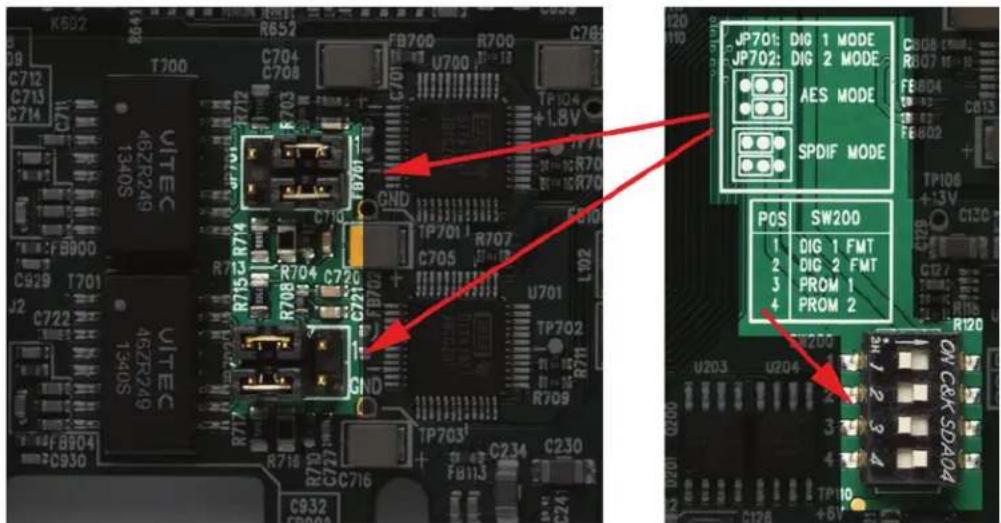
- The E22/E44 Digital I/O is set to AES by default. If you would like to switch the protocol to SPDIF, this is done with jumpers JP701 and JP702 to set the mode, and switch SW200 to set the format. In the case of the E44 you can switch both Digital I/Os to SPDIF or have one be SPDIF and the other AES. Remember that both the jumpers and switches must be altered to go from the default of AES to SPDIF. To set the mode, refer to the graphic below for jumpers JP701 and JP702. The format is set using SW200: Switch 1 controls Digital In/Out 1, while Switch 2 controls Digital In/Out 2 (E44 only). The OFF position selects AES format (default) and the ON position selects SPDIF format.
- Remove the cover from your computer chassis and select an empty PCI Express slot in your computer.
- You should refer to your computer system documentation for any special instructions on installing expansion cards and peripheral equipment.
- Unscrew and remove the slot cover from your selected PCI Express slot.
-
Insert the E22/E44 into the selected PCI Express slot and press it down so that the contacts are securely seated.
-
Secure the bracket of the card to the computer chassis using a chassis screw or retaining bracket.
- Replace the computer chassis cover and reconnect the power cord.
- Connect the Audio and Sync cables to the E22/E44. Refer to Section 5.3: Cable Connections for more information.
- Install software using the installation procedure for your computer type and operating system from the following section.
5.2 Installing the Lynx Driver
Lynx Drivers and firmware updaters are updated regularly. The most current versions can be easily downloaded from the Lynx Website: http://www.lynxstudio.com/ > Support> Downloads. Make sure that you choose Lynx E44 or Lynx E22 as the "Product".
If you are updating an existing driver, the driver installation program will automatically remove the old driver when the new one is installed. When installing drivers, make sure that all software programs, especially audio applications, are closed.
The steps below will presume that the appropriate driver has been downloaded to your computer.
5.2.1 Windows 7 (32-bit or 64-bit) or Windows 8
- Locate the E44/E22 driver from your downloaded files. The file name will be V2Setup###.exe (where ### is the version number of the driver)
- Double-click the installation file to start the driver installation
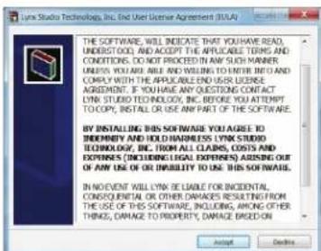
- Accept the License Agreement by clicking "Accept"
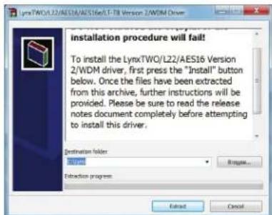
- The installer will extract the necessary files to the C:\Lynx directory. Click "Extract" from this window
-
If you are prompted to let the program make changes to the computer, select "Yes"
-
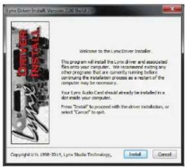
You will next see the driver Install dialog. Click "Install"
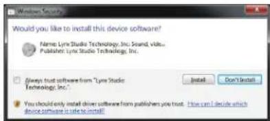
- You may get a Windows Security Dialog Bog. If so, select "Install"
-
Driver installation will proceed
-
Finally you will receive a confirmation that the install completed successfully
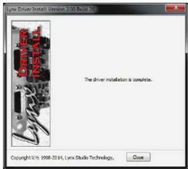
- The card is ready to use, no reboot necessary
NOTE: The driver installation process installs both the Windows driver and the Lynx Mixer application. The Lynx Mixer application is installed into the Lynx Studio Technology program group
5.2.2 OS X
- Locate the Lynx driver from your downloaded files. The file name will be Lynx_OSX_##.zip (where ## is the version number of the driver). Double-click to expand the installer package.
- Double-click "Lynx OSX.pkg" that was expanded from the step above. This will start the driver installation.
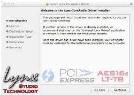
- Click "Continue" at the "Install Lynx CoreAudio Driver Installer" dialog box
- Click "Continue" for the Software License Agreement after reading it
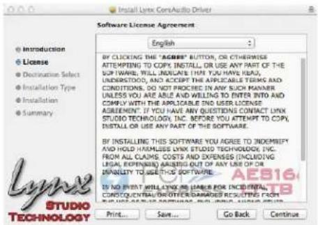
- Click "Agree" from the next Window
- Click "Install" in the Standard Install Window
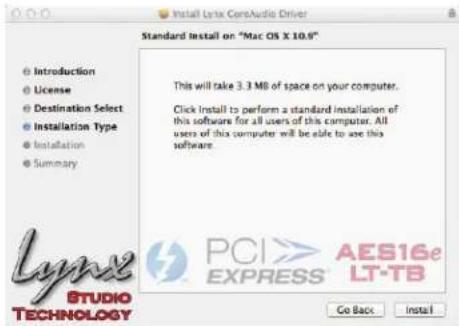
-
Type in Password and click "Install Software"
-
Click "Continue Installation" for prompt about restarting computer after the installation
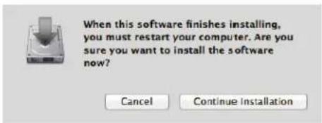
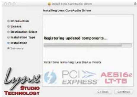
- The installation will continue
- When complete, you will be prompted to restart the computer
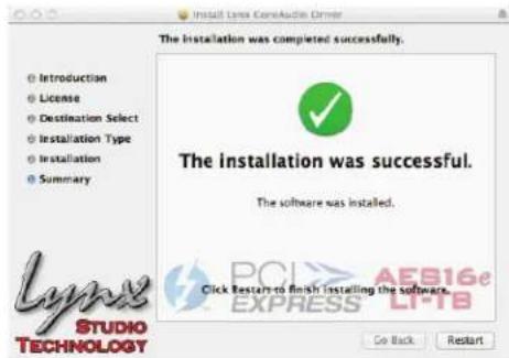
- After restart the driver will be installed and ready for use
NOTE: The OS X installation process installs both the Core Audio driver and the Lynx Mixer application. The Lynx Mixer application is installed in the “Applications” folder.
5.3 Cable Connections
The cables for the E22 and E44 cards are optional. If you only need analog I/O connections then only the analog cables would be necessary. If only digital I/O is necessary, only the digital cables would be required. Word clock connections are on the digital cables only.
This chart details the cable options and features:
| Cable Set | I/O Types | Target Card | Length |
| CBL-L2AUDIO A 4 | Analog I/O E44 6 feet | ||
| CBL-ESYNC 2 | Digital I/O, Word clock I/O E44 6 feet | ||
| CBL-L22AUDIO 2 | Analog I/O E22 6 feet | ||
| CBL-L22SYNC 1 | Digital I/O, Word clock I/O E22 6 feet |
5.4 Clock Settings and Connections
The E22/E44 supports sample rate from 44.1kHz to 192kHz and all of the common rates in between.
For the majority of E22/E44 users, keeping the default clock source of “Internal” is the best choice. In this state, the card is running from its own onboard crystal clock generator. This is a reliable, accurate and low jitter clock source, suited for the most demanding of contexts. Also, when the card is clocked internally, it will respond automatically to sample rate changes from audio software or the Operating System.
There are cases though where one would want to slave the card to an external source: where there is a house clock generator, or a context with multiple pieces of digital equipment, or even a computer system with multiple Lynx PCIe cards. We will look at the appropriate Lynx Mixer settings for different clock sources and the cable connection considerations below:
5.4.1 External Clock
The E44/E22 can slave to a master/house clock source via word clock. Word clock connections are provided with the Digital cable sets, either the CBL-ESYNC for the E44 or CBL-L22SYNC for the E22. Connect a word clock cable from the clock source to the BNC port labelled “Clock In” on the Lynx cable. In the Lynx Mixer, “EXT” should be selected as the Preferred Clock Source. In this state, it is important to verify that the clock source is operating at the same sample rate as the audio being played. If the card is receiving a valid clock signal, the sample rate will be displayed next to “External” in the Preferred Clock Source section of the Lynx Mixer Adapter.
5.4.2 Digital In
When Digital In is selected, the card will slave to the clock that is presented to its digital inputs. In the case of the E44, where there are two pairs of digital inputs available, you can choose between “Digital In 1” or “Digital In 2”. As with word clock, it is crucial that the clock source be set to the same sample rate as the project or audio file being played.
If the clock source is a SPDIF device, make sure that the digital input is configured for SPDIF (see Section 5.1: Hardware Installation).
5.4.3 Multiple Lynx cards
The E22/E44 cannot be used in a system with Lynx PCI cards, such as the AES16 or LynxTWO. However, multiple E22/E44 and Lynx AES16e cards can be used in one computer. Up to four of any combination of PCIe Lynx cards can be used in a single system. In a multi-card system there are two primary options for insuring clock synchronicity:
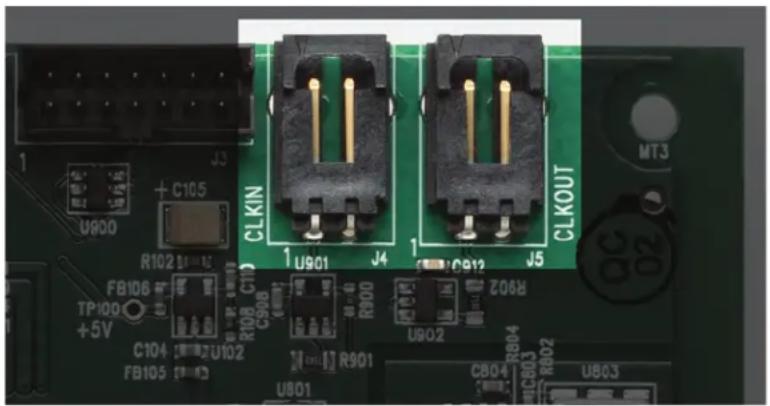
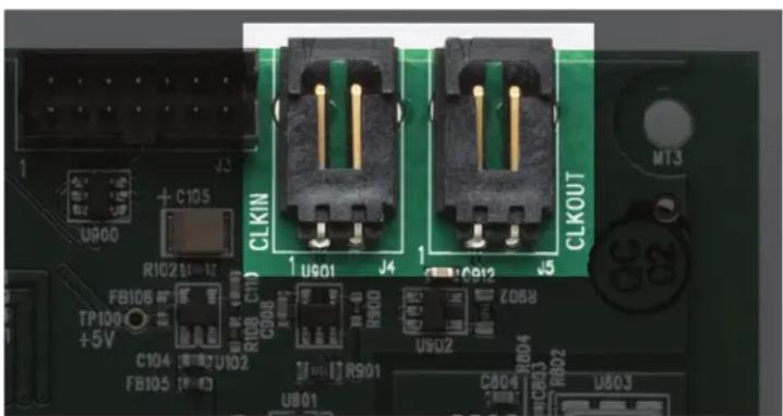
A. The first way is to have one Lynx card be the clock master. In this scenario, clock is distributed internally from one card to the others. Each Lynx card has two clock header connections on the PCIe edge of the board. One connector is labelled “Clock In” and the other is labelled “Clock Out”. The Lynx CBL-ICC cable is used to connect these ports together.
natural_image
Close-up of a green printed circuit board with black connectors and labeled pins (no readable text or symbols beyond component labels)Connect the CBL-ICC cable from the “Clock Out” of the card that you wish to be Card #1, to the “Clock In”: of Card #2. If there are more than two cards in the system, continue to daisy chain: “Clock Out” from card 2 to “Clock In” for card #3, etc. If there are four cards in the system, we would not recommend this clock method. Instead, all cards should be clocked externally for optimal performance.
In multiple Lynx card configurations, cards are identified numerically as Card #1, Card #2, etc. in the Lynx Mixer as well as in the driver devices that you will see in your recording software. The card order can be changed after the fact by the user, from within the Lynx Mixer. See Section 8.1.2: Setting device order. In a multi-card configuration it is essential that the card that is the clock Master be Card #1.
For the slave cards, make sure that a sample rate shows up next to “Header” in the Preferred Clock Source section of the Lynx Mixer, and select that as the clock source.
B. As an alternative, all the Lynx cards can be clock slaves in a multi-card configuration. In this case, word clock or digital in can be selected as the clock source, depending on the overall configuration. It is essential that there is a single Master clock source in the system, either a converter or dedicated clock generator. When more than three digital devices are being used, we recommend investing in some sort of clock distribution hardware. This insures solid clock performance and phase coherence for all connected devices.
Clocking in a complex studio environment can be an art. Always feel free to check with Lynx Tech Support for recommendations.
5.5 Audio Devices
The E22 will appear to the operating system as a 4-channel device, 2-channels of Analog I/O and 2-channels of Digital I/O. The play devices are labeled as Play 1-4, and the record devices are labeled as Record 1-4.
The E44 will appear to the operating system as an 8-channel device, 4 analog plus 4 digital. The play devices are labeled as Play 1-8, and the record devices are labeled as Record 1-8.
5.6 Device Order
In a multiple card configuration, some of the newer operating systems have a tendency to cause the order of devices to switch. For instance, on one boot cycle Card A will be device 1 and Card B will be device 2 within the OS. After a different boot cycle, this may change so that Card B is device 1 and Card A is device 2.
The Lynx Mixer has a solution to this dilemma. Please see 8.1.2: Setting Device Order, for details.
5.7 Verifying Successful Installation
To verify that the driver was successfully installed and is operational, launch the Lynx Mixer application. In Windows this can be found at Start > All Programs > Lynx Studio Technology > Lynx Mixer. In OS X the Lynx Mixer can be found in Applications.
If the Lynx Mixer opens without error, then the hardware has been successfully installed. If there is an error message on launch, check Section 10: Troubleshooting, or contact Lynx Technical Support.
6 Getting Started
With the drivers and Mixer application installed, the E22/E44 can now be used with most popular third-party audio applications. However, it is a good practice to verify that the system is functional by testing the card with the following procedure.
6.1 Windows Quick Audio Test
The installation of your card can be tested using the Lynx Mixer and the Lynx Demo application that is installed automatically by the driver installer. This is a quick way of verifying that the interface is installed correctly and properly connected to your external equipment.
- Connect Analog Output 1+2 of the E22/E44 to monitoring equipment capable of delivering an audio signal for listening via headphones or speakers. These are the outputs used for this test.
- Open the Lynx Mixer. We want the card to be in its default state for this test, so click Mixer >Restore Defaults.
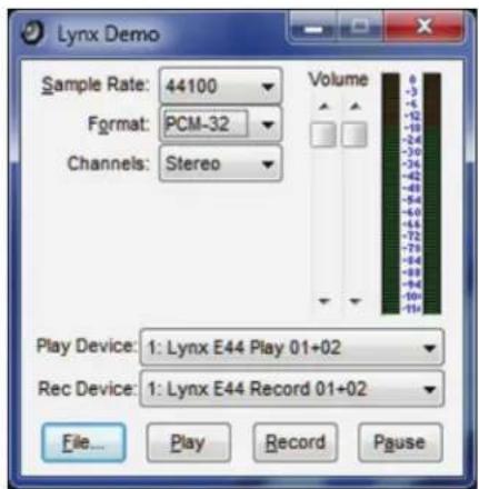
- Open the Lynx Demo application by clicking Start > All Programs > Lynx Studio Technology > Lynx Demo. The Lynx Demo program should appear in the upper left corner of your screen. Make certain that the Play Device is set to “eXX Speakers”.
-
Download "SineWaveMinus16.zip" from the www.lynxstudio.com website: Support > Downloads > Product=E22/E44 > OS = Windows > All Files. Save it to the computer's desktop. Double click the file to extract SineWaveMinus16.wav
-
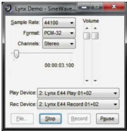
In Lynx Demo, click "File" and navigate to the computer's Desktop, then select "SineWaveMinus16.wav" and click "Open."
-
Click "Play." You should see the progress bar move from left to right.
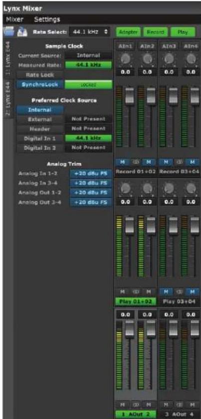
- Launch the Lynx Mixer application. Check the Outputs pane at the bottom. Check for meter activity for AOut (Analog Outputs) 1&2. If you have speakers or headphones connected to your destination device, you should be hearing audio as well.
If the test did not operate as described or you received any errors, please refer to Section 10: Troubleshooting.
6.2 Macintosh Quick Audio Test
The installation of your E22/E44 can be tested using the Lynx Mixer application and the iTunes software that is included with OS X. This is a quick way of verifying that the interface is installed correctly and properly connected to your external equipment.
- Open Audio MIDI Setup from Applications > Utilities.
- If the Audio Devices window does not appear automatically, then select "Show Audio Menu" from the "Window" menu.
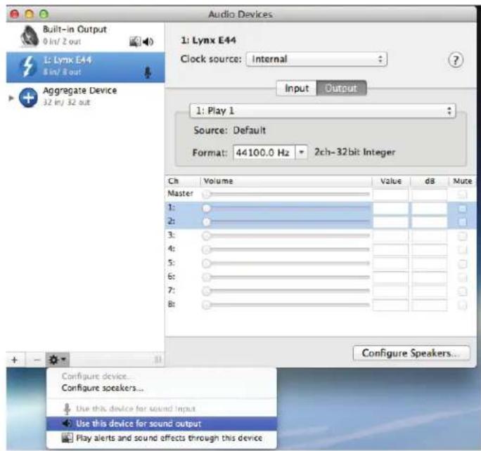
- All available audio devices will appear in the left pane. Locate the E22/E44 from this list.
-
Select this device. From the Gear icon in the bottom left corner, click "Use this device for sound output"
-
Download “SineWaveMinus16.zip” from the www.lynxstudio.com website: Support > Downloads > Product=E22/E44 > OS = OS X > All Files. Save it to the computer’s desktop. Double click the file to extract sinewaveminus16.wav
-
Connect Analog Output 1+2 of the E22/E44 to monitoring equipment capable of delivering an audio signal for listening via headphones or speakers. These are the outputs used for this test.
-
Open the Lynx Mixer. We want the card to be in its default state for this test, so click Mixer >Restore Defaults.
-
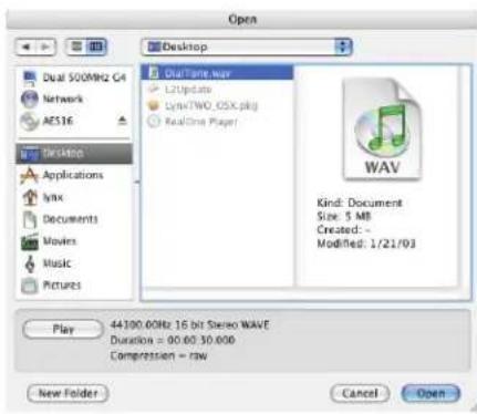
Launch iTunes from "Applications" or from the OS X dock. Drag the "SineWaveMinus16.aif" file from your desktop into the iTunes song list
-
Highlight this file from the song list and click the Play button. Make sure that the iTunes progress bar is moving from left to right.
-
Open the Lynx Mixer and show the Play Panel. Check for meter activity for AOut (Analog Outputs) 1&2. If you have speakers or headphones connected to your destination device, you should be hearing audio as well.
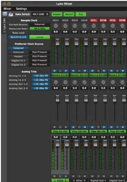
If the test did not operate as described or you received any errors, please refer to Section 10: Troubleshooting.
7 Lynx Mixer Application Reference
The Lynx Mixer application allows control of card parameters from a convenient software interface. It also provides accurate real-time metering for all inputs and outputs, and displays status information, sync source and sample rate. The Lynx Mixer is automatically installed with the driver setup program for Windows or OS X.
7.1 Starting the Lynx Mixer Application within Windows
Click: Programs > Lynx Studio Technology > Lynx Mixer.
7.2 Starting Lynx Mixer Application within OS X
From Finder, click Applications >Lynx Mixer.
7.3 General Operation
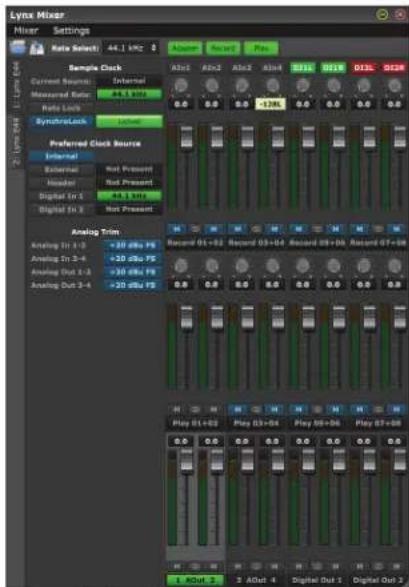
The Lynx Mixer is a single screen app for controlling the routing and various features of the E22/E44. The software simply reveals and facilitates changes to the hardware, so the Mixer will not launch if a Lynx card is not installed and functional. In addition to the controls on the Main Window there are two menus with additional features.
For multi-card installations, there are tabs on the left side of the screen for each card. When the tab is clicked, then the settings on the main screen, and in the menus, pertain to that individual card. This makes managing a large amount of I/O simple, and allows for keeping settings and connections well organized.
Each card in a multi-card system is marked by a numeric identification. The order of devices can be changed, and will be covered in Section 8.1.2: Setting Device Order. Each card's position, from first to last, will be consistent with the order that the interfaces appear to your
software applications (the exception being non-ASIO software under Windows: see Section 8.1.4: Configure for use).
Most features are identical for the OS X and Windows versions, but there are a few OS-specific controls. These will be pointed out as such in the sections below.
7.3.1 Navigation Bar
The bar at the top of the Lynx Mixer main window, provides access to commonly used functions, and allows for customizing the displayed elements. Doing a “mouse over” will cause a pop-up to appear over each icon in the Navigation Bar, with a short description of the associated function.

① Open Scene
This feature allows user-defined mixer scenes to be restored. Mixer scene files can be saved to any directory on the computer's hard drive. After clicking "Open Scene", navigate to the directory where the desired scene file has been saved, highlight the file and click "Open."
Opening a scene file will cause the Lynx Mixer to instantly adjust to the parameters states which were saved in the scene. In a multi-card system, a scene restores the state of ALL Lynx cards in the system. Mixer scenes can be a quick and easy way to flip between two commonly used contexts of use, like Recording and Mixing for instance.
2 Save Scene
This feature provides the ability to save all user-selectable parameters. “Scenes” that contain the state of all mixer settings can be saved to a file on the computer hard drive. Recalling Scenes is a very quick and efficient way to revert the mixer to an appropriate state for different contexts of use.
Since scene files are stored on your local disk drive, there is no limit to the number of scenes that can be stored. After “Save Scene” is selected, A File Name will need to be created and a directory selected for the mixer scene file to be written to. The current mixer parameters will be stored into the scene file. Selecting an existing scene name and clicking the Save button will overwrite that scene with the current parameters.
To delete a scene simply delete the mixer scene file from the disc drive.
NOTE: When the computer is shut down, the current mixer state is saved. When the computer is restarted, the mixer state is restored. This function is independent of Mixer Scene operation.
③ Rate Select
This button displays the current sample rate of the Lynx card and can also be used to select a desired sample rate when the card is operating off of its Internal Clock. However, when on Internal clock, the sample rate is generally determined by the audio application being used, or the default sample rate settings in the operating system.
4 Adapter
This button toggles whether the Adapter settings are visible from the Main window or not. The Adapter section, when visible, appears on the left part of the screen.
5 Record
This button toggles whether controls for the Record Sources are visible from the Main window or not. The Record Source section, when visible, appears as the top pane of faders in the Lynx Mixer.
⑥ Play
This button toggles whether controls for the Play Sources are visible from the Main window or not. The Play section, when visible, appears as the middle pane of faders in the Lynx Mixer.
7.3.2 Adapter Section
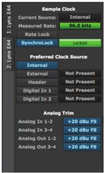
The Adapter Section is where the clock settings for the Lynx Card are established and monitored.
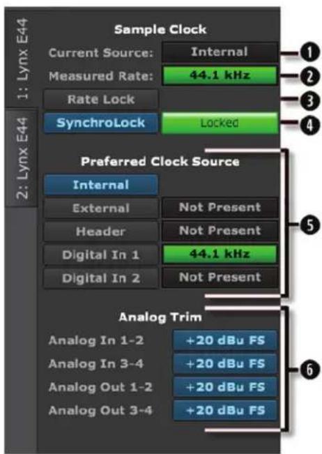
① Current Source
This displays the clock source that is active. This may differ from the selection in the “Preferred Clock Source” section, if an invalid or offline clock source had been chosen there.
② Measured Rate
Whether the card is operating from its Internal Clock, or some External Clock Source, this button displays the sample rate that the onboard frequency counter is measuring.
③ Rate Lock
When the CURRENT SOURCE is “Internal” and RATE LOCK is “ON”, the driver will ignore all requests to change the Sample Clock Rate, including those coming from applications. This effectively causes all files not running at the currently selected
clock rate to be software sample rate-converted by the Operating System during playback or recording. When clocking to an external clock source, the Rate Lock function is effectively ON regardless of this switch setting, and the rate is locked to the same rate of the incoming clock.
RATE LOCK On is primarily useful in cases where material of various sample rates may be played, but a static sample rate is desired - for instance when digital devices are connected that don't support all of the sample rates desired.
4 SynchroLock
This button can turn the SynchroLock clocking system On and Off. SynchroLock is Lynx's proprietary technology for attenuating jitter on clock inputs and providing a stable clock for all digital signals passed through the E44/E22.
This button also shows the status of the SynchroLock clocking system. Prior to achieving lock, the four green LED's give an indication of the completion of various lock stages. During this time the wide range analog PLL maintains lock.
Working: In this state SynchroLock is analyzing the input clock signal and making adjustments to frequency and phase. This process typically takes two to three minutes to complete. The four LED's show progress towards final lock: One green LED denotes frequency lock to 3.2 ppm accuracy, two LED's denote frequency lock to 1.6 ppm accuracy, three LED's denote frequency lock to 0.6 ppm and the transition to the phase lock stage, four LED's denote the start of the phase lock stage. When phase lock has been achieved, the Yellow "Working" indicator changes to the green "Locked" indication.
Locked: Indicates the SynchroLock system has achieved final lock to an incoming clock signal. This indicator will also appear when the SYNC SOURCE is set to "Internal".
Range: Indicates that the selected external clock source is not within the SynchroLock lock range.
Disabled: Indicates that SynchroLock has been manually turned Off.
5 Preferred Clock Source
This section of the mixer provides control of the system sample clock generator. All E22/E44 play and record devices on a single card MUST have identical sample rates since there is one on-board generator. Sample rates cannot be changed while the system is playing or recording, unless “Allow Clock Change if Active” is selected from the Lynx Mixer Settings > Advanced menu. Clock sources available to choose from are:
Internal: Clock derived from the on-board crystal oscillator
External: Clock signal from BNC WORDCLOCK connector
Header: Clock signal from Clock In Header pins on the card, generally for clocking to another card installed in the system.
Digital In 1: Clock signal from the Digital Input labeled "In 1"
Digital in 2: Clock signal from the Digital Input labeled “In 2” (E44 only)
If the selected Preferred Clock Source is not also displayed as the Current Source in the SAMPLE CLOCK section of the Adapter page, it would be for one of the following reasons:
- The selected source is not present or the connected device is not generating a valid clock signal. In these cases, the card will operate from its internal clock until a valid clock signal is connected to the selected clock source.
- The selected clock source is generating a sample rate outside of the card's usable range (i.e. 22kHz). This can be corrected by setting the clock source to a supported sample rate: 44.1kHz, 48kHz, 88.2kHz, 96kHz, 176.4kHz, or 192kHz.
- The Clock Source was selected when the driver was being accessed by some software application. In this case, the Preferred Clock Source will become the Current Source when the card is no longer being accessed. If “Allow Clock Change if Active” is selected from the Lynx Mixer Settings > Advanced menu, then a new Preferred Clock Source can become the Current Source while the card is being accessed from a software application.
6 Analog Trims
The card's Input and Output Trims can be switched between +20dBu and Variable Trim. +20dBu is the default for all inputs and outputs, and is suited to most professional audio contexts. Please note that +20dBu refers to a full-scale level. This is the same trim level used
in older Lynx products such as the LynxTWO when switched to a +4 trim setting. This refers to a nominal +4dBu level with 16dB of headroom. Switching to Variable Trim changes the Trim level to +6dBV – the same level of the LynxTWO and Aurora products when put into the -10dBV trim position. This is the factory default state, but can be changed to the desired reference level with the Trim Pots on the card itself. These levels can be set anywhere from 0dBV (consumer levels) to +24 dBu. With the variable trim option, any piece of gear from low-end consumer audio pieces to high-end post production gear can be easily accommodated. Input and output trims can be set independently for any pair of channels. The E44 card will display trims for all four inputs and outputs, the E22 will show them for two ins and outs. For details about setting input and output levels with the onboard Trim Pots, see Section 8.3: Onboard Variable Trim Pots.
7.3.3 Record Section
The top row of faders on the Main Screen is the Record Section of the Lynx Mixer. The purpose of this section is to:
- Show input signal meter activity.
- Allow assignment of physical inputs to record devices within the operating system.
- Manage the levels, routing, and pan positions of input signals being monitored through the Lynx card's outputs.
Eight channels will appear with an E44 card. Four channels for an E22. This section can be “hidden” by clicking the RECORD button in the Lynx Mixer Toolbar. When the section is hidden, all of the settings are still active. Clicking the RECORD button again will make the section visible again.
Some of the controls and displays here are pertinent to the hardware inputs themselves and some are specific to the hardware monitoring settings for that input. We will look in detail at each control.
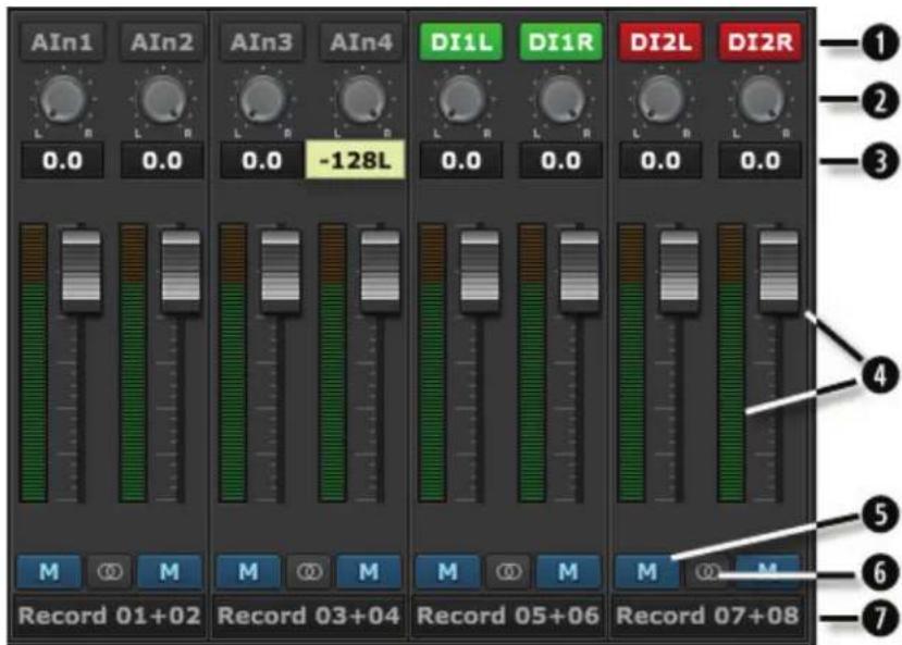
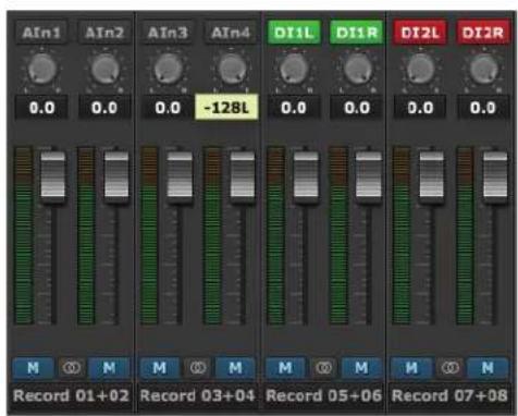
① Input Source selection
This button reveals which physical input is assigned to the corresponding Record Device at the bottom of the pane. The default configuration is for Analog Input 1 to be assigned to Record 1, Analog Input 2 assigned to Record 2, etc. With an E44 eight record channels
will appear here, with an E22 four record channels will appear.
Input names are abbreviated so that they can appear in 4 spaces. Sources that start with “A” are for Analog and with “D” are for Digital. For instance, “AIn4” means Analog Input 4, “DI2L” means Digital In 2 Left (Note: digital inputs have a stereo orientation, analog have a mono orientation).
Clicking the Input Source button generates a menu with all of the Analog and Digital Inputs available to choose from. For the vast majority of users the default configuration is ideal and would never be changed. There are a few reasons why assigning inputs other than the defaults may be beneficial:
- Assigning the same physical input (i.e. Analog In 1+2) to multiple Record devices can allow the user to record the same signal into two different programs or onto two different tracks within the same program.
- If the Digital Inputs are being used primarily and not the Analog Inputs, it can be useful to assign the first record devices to the Digital Inputs instead of Analog, so that they appear first in the list. For an E44 user, it may be advantageous to have the Analog and Digital inputs appear in contiguous pairs, rather than the default arrangement of the four Analogs First and then the four Digitals.
When an input source button shows a Digital Input, the button will be Green when that Input is locked to a valid digital signal, or it will appear as Red when no clock signal is present.
2 Pan Pot
The Pan Pot knob controls the pan position of the input as it is being monitored through an output. IT HAS NO EFFECT ON THE RECORDED SIGNAL. It is only pertinent to monitoring.
Hardware based, no latency input monitoring is implemented by clicking on a physical output button at the bottom of the mixer screen. For instance, in the screen picture below, Analog Out 1 and 2 have been selected (Output selection is always done with stereo pairs):
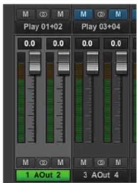
The Output label appearing in green indicates that this is the Selected Output. A different Output can be selected by clicking a different pair's Output button. In this state, any of the Sources in the Input Section can be routed to this output. For instance, if we have an input signal on Analog In 3, and we wish to hear it through Analog Out 1+2, Select Analog Out 1+2 in the bottom of the Outputs Section, then un-mute Analog In 3 in the Inputs Section. Now signals from Analog Input 3 will be heard through Analog Output 1. If we would like to hear the signal through Analog Outputs 1+2 both, then the Pan Knob can be used to pan Analog In 3 to the center, or anywhere within the stereo spectrum.
By default, Odd number inputs are panned to the left, and Even number to the right.
3 Numeric Level Indicator
This displays the amount of attenuation performed on the associated record source. This is attenuation for the Monitor level of the signal; it has NO bearing on the level being recorded
into an audio application. It is applicable to Monitoring Level only (how loud that signal source is through the output you are listening to).
4 Faders and Meters
The METERS on the Input section show the peak level of the signals at the associated input. Since there is no way to attenuate the level of the signal being recorded (except for the rotary Trim controls, see Section 8.3: Onboard Variable Trim Pots), the METER level will reflect the signal that will be recorded into audio software. The METER will not reflect attenuation to the input signal as it is being monitored. When you lower the fader, the METER level will not change, however the change WOULD be reflected in the meters of the output this signal was routed to.
The FADERS are for attenuating the signal of the input as it is being hardware monitored. For instance, if you are routing a signal from Analog Input 2, through Analog Output 3+4, and the input signal is too loud relative to the rest of the mix, you would lower the fader under AIn2 to correct that. The signal level being recorded for Analog In 2 will not change, but the level will decrease through the outputs as you are monitoring the performance.
The Fader position is specific to the routing between the input and an output. So, using the example above, if you have attenuated the signal of Analog Input 2 through Analog Outputs 3+4, but then you select Analog Output 1+2 from the Output Pane, the fader for Input 2 will return to whatever position is established for that routing.
To reiterate, the faders are for the level of a specific routing between an input and an output. It will not affect the level of the input source monitored through an output that is not selected, nor will it affect the level of the audio being recorded.
⑤ Mutes
The “M” Icon below the fader is for the Mutes. This switch Mutes or UnMutes the input signal routed to an output. As with the faders, this control is specific to the patch point between the Input Source, and the selected output. It does not
control whether the input signal itself is muted, or whether that input signal can be recorded.
When the “M” button is blue like this M, then the Mute is ON, and no signal will pass to the selected output. When the “M” button is gray, like this M, then the Mute button is OFF, and signal WILL pass to the selected output.
Inputs are muted by default. When an output is selected from the outputs pane, inputs need to be un-muted to become active. When an input source is no longer being monitored, then it is good practice to mute it again so that unintended mic bleed or system noise is not corrupting the signal path.
6 Channel Link
In between the two Mute buttons for a pair of Inputs, is the channel link control: Ⓞ. This control toggles the linked state for a pair of faders and mutes. If two channels ARE linked, then moving the fader for one of them will move both channels. Similarly, if one is muted then both will mute. If the faders between the channels are offset, when one is moved the
other will snap to the same position. The linked state also impacts the Pan controls. If one pan pot is moved to the left the other will move a corresponding amount to the right. For instance, if the left pot is set to -25, the right channel will pan to +25.
Linked is the default state for pairs of inputs. To “un-link” a pair, click on the link icon and it will change to a single circle: ☐. In this state, the mute, fader and pan controls operate on a single channel independently.
7 Record Source Label
This identifies the Record Source that is applicable to the fader, pan, mute and input select controls. The Record Source is the driver device that you will see from an audio software application. For instance, if you are viewing the Record 3+4 fader strip, and you have Analog Inputs 3+4 assigned to it, when you select Record 3+4 in a track in your recording software you will get signals from Analog Inputs 3+4 streaming to that track.
7.3.4 Play Section
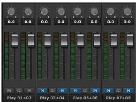
The middle row of faders on the Main Screen is the Play Section of the Lynx Mixer. The purpose of this section is to reveal and control playback streams from the computer. Monitoring levels, pan or balance, mirroring of streams, and muting can be easily set here.
With an E44 there will be four pairs of faders here; with an E22, two pairs. This section can be “hidden” by clicking the PLAY button in the Lynx Mixer Toolbar. When the section is hidden, all of the settings are still active. Clicking the PLAY button again will make the section visible again.
Here is a breakdown of each element in this mixer section:
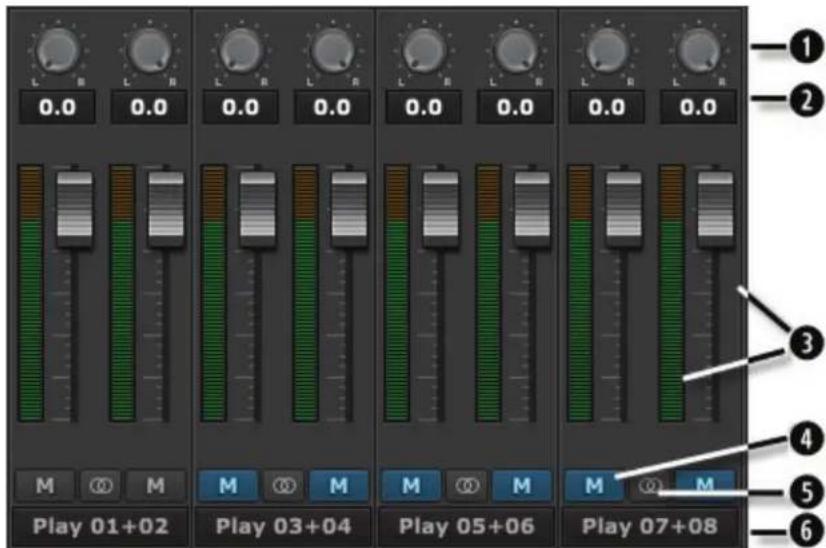
① Pan Pot
Software Play devices in modern operating systems tend to have a stereo orientation.
However, there can be cases when DAWs are configured with Mono playback streams. The PAN controls will allow you to position a play stream anywhere within the stereo field. If two Channels are Ganged (i.e. Play 1 +
Play 2), then moving one pan control to the left will make the ganged channel's pan control move a corresponding value to the right.
As with the record section, this will affect the Play stream as it is routed to physical outputs. It is the pan position for that specific patch point. Play streams are assigned to physical
outputs by selecting the desired Output from the bottom fader group in the Mixer, and then un-muting play channels that are to be routed to that output. If a pan position established for Play 1 is assigned to Analog Output 1, there can be a different pan position for Play 1 assigned to Analog Output 3, as an example.
2 Numeric Level Indicator
This displays the amount of attenuation performed on the associated play device. This is attenuation for the Monitor level of a play stream routed to a specific output. As with panning, you can have Play 1 attenuated by 10dB when it streams to Analog Output 1, but no attenuation when streaming to Analog Output 3. Clicking the Outputs on the bottom pane of the Lynx Mixer, reveals the channel assigned to that output, and the associated pan and fader states.
3 Faders
The FADERS are for attenuating the level of a playback stream routed to a specific output. As with panning, this level is specific to a play stream routed to a specific output. It is not to be confused with adjusting the level of the Output itself. That is handled in the bottom pane of the Lynx Mixer.
4 Mutes
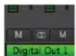
The “M” Icon below the fader is for the Mutes. This switch Mutes or UnMutes the play stream routed to an output. As with the faders, this control is specific to the patch point between the play stream, and the selected Output. It does not control whether the play stream itself is muted, just the play stream routed to a specific output.
When the “M” button is blue like this M, then the Mute is ON, and no signal will pass to the selected output. When the “M” button is gray, like this M, then the Mute button is OFF, and signal WILL pass to the selected output.
Play channels are pre-routed by default. Play 1+2 is routed Analog Output 1+2, Play 3+4 is routed to Analog Output 3+4 on an E44, and Digital Out Left/Right with an E22. With an E44, play 5-8 are assigned to the Digital Outputs
For most users, the default is appropriate and will never need to be changed.
There are a number of cases where customizing the play stream destinations can be useful. Sometimes mirroring a play stream to multiple outputs, changing the device order (so, for instance Play 1+2 goes to the Digital Outputs), or just for cases where inputs and play streams are routed to an output and you just want to isolate the input signals and mute the play streams.
With an output selected in the Outputs Pane, mute or un-mute play channels as needed. You can have multiple play streams go to the same output, or a single play stream going to multiple outputs. It is good practice to save a scene whenever such alterations are made, so you can easily return to the customized state.
⑤ Channel Link
In between the two Mute buttons for a pair of Inputs, is the channel link control: ☐. This control toggles the linked state for a pair of faders and mutes. If two channels ARE linked, then moving the fader for one of them will move both channels. Similarly, if one is muted then both will mute. If the faders between the channels are offset, when one is moved the other will snap to the same position. The linked state also impacts the Pan controls. If one pan pot is moved to the left the other will move a corresponding amount to the right. For instance, if the left pot is set to -25, the right channel will pan to +25.
Linked is the default state for pairs of inputs. To “un-link” a pair, click on the link icon and it will change to a single circle: ☐. In this state, the mute, fader and pan controls operate on a single channel independently.
6 Play Channel Label
This identifies the Play Channels that are applicable to the fader, pan, mute and input select controls. The Play Channels are the driver devices that you will see from an audio software application. For instance, if you are viewing the Play 3+4 fader strip, and Play 3+4 is assigned to Analog Outputs 1+2, then when you select Play 3+4 as the output in your audio software, when you play audio it will be streamed to Analog Out 1+2. As mentioned though, Play channels are pre-routed by default. Play 1+2 is routed Analog Output 1+2, Play 3+4 is routed to Analog Output 3+4 on an E44, and Digital Out Left/Right with an E22. With an E44, play 5-8 are assigned to the Digital Outputs
7.3.5 Outputs Section
The Outputs Section of the Lynx Mixer is a fixed entity. It cannot be hidden as the Play and Record panes can. This is because the Lynx Mixer has an Outputs-driven perspective. The other panes essentially involve managing what sources feed the card's physical outputs.
The channels shown will be appropriate to the card used. There will be 8 output channels for an E44 (4 analog and 4 digital), and there will be 4 channels for an E22 (2 analog and 2 digital).
Let's look at the elements here:

① Numeric Level Indicator
This Level Indicator displays the amount of attenuation in dB performed on the associated Output.
② Faders and Meters
The FADERS in the Outputs Pane are for attenuation of the output levels. Levels can be reduced in 12 dB increments with a click-drag of the mouse.
This is the rough equivalent to turning down the faders on a mixing board. If there are several sources assigned to that output, play and record sources, all will be attenuated when the faders are brought down.
All faders can be attenuated at the same time by holding down the CTRL key on the keyboard while click-sliding any single fader.
The METERS in the Outputs section show the level strength of the signals at the associated output. The Meters are post-fader, so there will be reduction in Meter level as the signal is attenuated.
3 Mutes
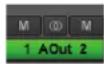
The “M” Icon below the fader is for the Mutes. This switch Mutes or UnMutes the associated output.
When the “M” button is blue like this M, then the Mute is ON, and no signal will pass to the selected output. When the “M” button is gray, like this M, then the Mute button is OFF, and signal CAN pass to the selected output.
4 Channel Link
In between the two Mute buttons for a pair of Outputs, is the channel link control. This control toggles the linked state for a pair of faders and mutes. If two channels ARE linked, then moving the fader for one of them will move both channels. Similarly, if one is muted then both will mute. If the faders between the channels are offset, when one is moved the other will snap to the same position.
Linked is the default state for pairs of outputs. To “un-link” a pair, click on the link icon and it will change to a single circle: ☐. In this state, the mute and fader controls operate on a single channel independently.
⑤ Output Button
This identifies the Outputs that are applicable to the fader and mute controls, and is also used to facilitate routing. As mentioned, the Lynx Mixer uses an Output oriented approach to routing. Clicking on an Output button, “selects” that output for sources to be assigned to it. When selected, the button is green. In this state, sources from both the Record and Play panes can be un-muted, thereby set to stream to the “selected” output.
In the Mixer's default state, each output has a play device routed to it. Play 1+2 is routed to Analog Output 1+2, Play 3+4 is routed to Analog Output 3+4 on an E44, and Digital Out Left/Right with an E22. With an E44, play 5-8 are assigned to the Digital Outputs.
To add sources to an output, click an output button to select it and it will turn green. Then un-mute Record and/or Play sources from the Record and Play Panes. Signals from those sources will now stream to that selected output. When multiple sources are assigned to a
single output, it is often necessary to attenuate the individual sources to prevent overloading and distorting the output.
7.3.6 Mixer Menu
| Mixer | Settings | |
| 1 | Restore Defaults | ctrl + R |
| 2 | Open Scene... | ctrl + O |
| 3 | Save Scene... | ctrl + S |
| 4 | About... | |
| Exit | alt + Q |
① Restore Defaults
This returns the Mixer to its factory default state. Routing, Sync Source, state of the Play and Record panes, all will be impacted. What is NOT impacted is device order, since that state is stored in the actual hardware.
Restore defaults is an excellent troubleshooting tool. When things are not going as expected, this is a good first step to try.
② Open Scene
This feature allows user-defined mixer scenes to be restored. Mixer scene files can be saved to any directory on the computer's hard drive. After clicking "Open Scene" navigate to the directory where the desired scene file has been saved, highlight the file and click "Open".
③ Save Scene
This feature provides the ability to save all user-selectable parameters. “Scenes” that contain the state of all mixer settings can be saved to a file on the computer hard drive. Recalling Scenes is a very quick and efficient way to revert the mixer to an appropriate state for different contexts of use.
Scene memory is global to all users on a single computer and is initially empty. There is no limit to the number of scenes that can be stored. After “Save Scene” is selected, A FILE NAME will need to be created and a directory selected for the mixer scene file to be written to. The current mixer parameters will be stored into scene memory. Selecting an existing scene name and clicking the Save button will overwrite that scene with the current parameters.
Scenes contain the settings for all units in a multi-unit system. To delete a scene simply delete the mixer scene file from the hard drive.
NOTE: When the computer is shut down, the current mixer state is saved. When the computer is restarted, the mixer state is restored. This function is independent of Mixer Scene operation.
4 About
This option displays information about the Lynx Mixer, driver, and firmware as follows:
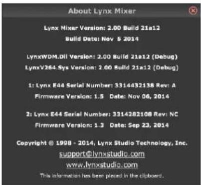
Mixer/Driver Version: Displays the current mixer version and build number.
Build Date: Displays the date the driver and mixer were released.
DLL and SYS versions (Windows only): These are driver system file versions, useful for diagnosing a potential versioning mismatch.
Device Name: Displays the name of the Lynx audio device installed. Up to six Lynx audio devices may be shown. In this case, E44.
Serial Number: Displays the serial number of the Lynx
Card.
Hardware Rev: Displays the hardware version of the Lynx Card.
Firmware Version: Displays the firmware revision of the Lynx Card.
Firmware Date: Displays the date the Lynx firmware was released.
PLEASE NOTE: The About Lynx Mixer window may display different information than what is shown here.
7.3.7 Settings Menu
In a typical system, the only selection here is “Always on Top”. When active, this places the Lynx Mixer forward no matter what other applications are active in the computer. By default, this setting is OFF.
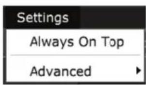
7.3.8 Settings > Advanced Menu
The Advanced Menu within the Settings Menu provides access to controls geared towards power users, and unique contexts of use.
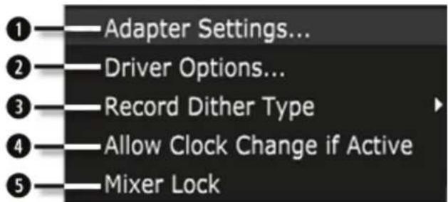
1 Adapter Settings
This page is for assigning the order for each card in a multi-card configuration. Current operating systems can alter device order for a variety of reasons. This can be problematic when a system is configured around a static device order. This page solves that by insuring that the intended device order does not change.
For instructions on how to use this tool, see Section 8.1.2: Setting Device Order.
② Driver Options (Windows only)
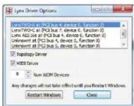
This page reveals options that involve how the card or cards interact with Windows. It is actually a separate program that is launched when this menu option is selected. The top pain shows any Lynx Cards that are installed in the system presently, or have been installed in the past. The other options will be specific to whichever Lynx card is highlighted in the list. These Include:
Topology Driver: This setting is for the connection between the
Windows Mixer and the Lynx Mixer. While checked, changes made to the Windows Mixer are reflected in the Lynx Mixer. Unchecked breaks this link, and can be useful when a program in Windows is causing mute states or level changes that are undesirable.
MIDI Driver: This is a legacy control that is not pertinent to the E22 or E44.
Num WDM Devices: This control allows reducing the number of play and record devices that appear to applications that use a Windows driver model (such as WDM, WaveRT, MME, etc. – does NOT apply to ASIO). For instance, if you are using an E44 and only need analog I/O, you can reduce the # of WDM devices to “4”, so that the digital devices do not appear to applicable audio programs.
3 Record Dither Type
Dither corrects for potential truncation artifacts when recording at a bit depth less than the conversion bit-depth, which with a Lynx card is always 24-bit. The Lynx Mixer dither function is only activated when recording files at bit-depths less than 24 bit. This option provides selection of the type of dither used on all record channels. The following options are available:
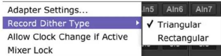
Triangular: Enables the addition of triangular probability density dither. Triangular is the preferred dither type in most cases.
Rectangular: This type of dither decreases the signal-to-noise ratio by 3 dB (less than triangular), but is less desirable because of its noise modulation effects.
4 Allow Clock Change If Active
This option allows the Current Clock Source to be changed even when the Lynx card is being used by an audio application. Please note: there will be an audible glitch when a clock source is changed during playback or recording of audio. With the Allow Clock Change if Active option OFF (the default), changing the Preferred Clock Source will not change the Current Clock Source until the driver is no longer being utilized by a software application.
Performance Buffers (OS X Only)
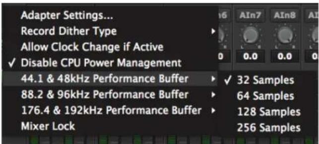
In some rare cases, optimal audio performance cannot be achieved by adjusting the Core Audio buffer sizes within an audio application. This problem can have a hardware or a software basis. Adjusting the performance buffer can help. The performance buffer refers to the size of audio “packets” that are written into, or read from, the buffers. In these rare case of trouble, doubling the performance buffer size can prevent data bottlenecks, and restore good operation. The Performance buffers are grouped according to sample rate range, so make sure and select the appropriate one for the sample rate being used when problems occurred. Also, it is important to remember that the performance buffer size must always be SMALLER than the Core Audio buffer size being used (i.e., the buffer size selected from within an audio application). See Section 8.2.1.4: Controlling Latency by Changing the Buffer Size for information about setting buffer sizes.
⑤ Mixer Lock
When checked, this switch enables a locking feature that prevents changes to any of the mixer controls by any application, including the Lynx Mixer GUI itself. This feature can be helpful when non-qualified personnel have access to the computer audio system.
8 Using the E22/E44
With the E22/E44 correctly installed in your computer, you can begin to use it with most popular third-party audio applications. In this section we will explore setting up the card for different contexts of use.
8.1 Configuring multiple cards
Up to four PCIe Lynx cards can be used in a single computer. Each unit will be addressable independently in the Lynx Mixer, and the combined I/O can be used by a DAW application.
Connecting multiple units is done in several stages:
8.1.1 Establish clock connections
In a multi-card configuration, with any combination of AES16e, E22 or E44 cards, it is critical that there be one clock master, and all other devices configured as clock slaves.
One of the cards could be a master in the system, or all of the cards could be slaves to an external clock source. There are many variations possible, but here is the general idea:
8.1.1.1 Card as Master
The AES16e and E22/E44 cards all are capable of generating a very accurate, low jitter clock derived from an onboard crystal oscillator, perfect for driving all manner of downstream devices.
One significant advantage of having a card as master is that sample rate changes from an audio application or from Operating System defaults will be responded to immediately. There is no need to manually select a sample rate in this scenario.
Clock must be distributed from the Master card to the other cards in the system as well as downstream digital devices (when present). The preferred means to deliver clock from one card to another is by using the Lynx CBL-ICC Internal Clock Cable. This cable connects to the internal Clock In and Clock Out connectors on the edge of the Lynx cards.
natural_image
Close-up of a green printed circuit board with multiple black connectors and labeled pins (no readable text beyond component labels)Select a card to be the master, and connect a CBL-ICC cable from its Clock Out header pins, to the Clock In pins of the first slave card. If there are more than two cards in the system, continue connecting Clock Out from Card #2 to Clock In of card #3, Clock Out from card #3 to Clock In of card #4, etc.
The physical position of the card selected as #1 does not matter, we'll look at establishing the card order in the Lynx Mixer in the next section.
For any other digital devices in the system that need to slave, clock will be generated from any of the cards' clock or digital outputs.
8.1.1.2 Cards as clock slaves
In a multi-card system, sometimes having a Master Clock, or using the clock from an external digital device can make the most sense. In these cases, the Lynx Cards can either slave to their word clock inputs or digital inputs. On the E22 and E44 cards, the digital I/O and word clock connectors are on the same cable set.
Although clock performance using Digital In versus Word Clock In should be negligible, it is advisable to keep the number of clock “generations” to a minimum. In other words, we want all connected devices within one or two steps from the clock source. If there are too many digital devices in the system to achieve that, then it is best to use some form of clock distribution for optimal clock performance.
8.1.2 Setting device order
Modern operating systems have a tendency to change device order somewhat randomly. If there are three devices, ordered 1, 2 and 3, after a reboot the order may have changed to 2, 3 and 1. This can wreak havoc on project templates, signal routing and workflow. We worked hard to devise a hardware-based solution to this quandary.
On first boot, when multiple units are installed, the driver will automatically assign each interface a numerical ID based on the position it's been assigned in the operating system. For most users there will not be a need to change this. The numerical ID is actually stored in the hardware, so if a card is moved from one computer to another, its numerical ID will remain the same.
In a multi-card system where one card is established as the clock master, it is essential that this card be established as card #1. The Master card will be the one that has the ICC cable going from its clock output, down to the other card or cards. If this card appears in the Lynx Mixer as something other than card #1, it should be changed.
Device order is set from the Lynx Mixer.
-
If the driver is not already installed, follow the procedure in Section 5.2: Installing the Lynx Driver. Reboot when prompted.
-
Launch the Lynx Mixer (Windows: All Programs > Lynx Studio Technology. OS X: Applications)
- The cards will each have their own tab on the left side of the Lynx Mixer. Click through each tab and look at the "Preferred Clock Source" columns in the ADAPTER section. Each card that has a sample rate next to "header" is a clock slave. The card that has no sample rate next to header is the clock Master. If this card is NOT the first tab (i.e. card #1) then its device order will need to be changed.
- Click Settings > Advanced > Adapter Settings. Lynx Cards should show up with their numerical identifier. For instance "3:E22" means this is an E22 that has hardware ID 3.
- Use the "Move Up" or "Move Down" buttons to change the order to what is desired. For instance, if you wish for the unit that appears as #3 to be #1, use the Move Up button two times. It should now appear as "1: E22".
- After completing your selections, click "Save", then close the Lynx Mixer. (IS A REBOOT NECESSARY?)
- To verify settings, re-launch the Lynx Mixer and make sure that the card in the #1 slot does NOT have a sample rate next to "Header" under Preferred Clock Source.
8.1.3 Setting clock sources in the Lynx Mixer
This step is directly related to the choices made in Section 8.1.1: Establish clock connections
The correct settings will be context specific. Set the Sync Source for each card from the Lynx Mixer by clicking the Tab for the device on the left side of the mixer page and choosing the desired clock source from the Preferred Clock Source section of the ADAPTER page.
See Section 7.3.2: Adapter Section for details.
If one card is the Master and the other cards slave via the ICC cable, choose “Internal” for the Master, and “Header” for the slaves. If all cards slave to word clock, select “External” for them all. If they slave to Digital Inputs, choose the appropriate “Digital Inputs”.
It is good practice to save a scene after configuring the mixer for use.
8.1.4 Configure for use (Windows)
In Windows, one can use the Sound section of Control Panel to select whichever card is desired as the default playback device. Unfortunately, Windows is known to jumble the device order here. To determine which unit in the list is the one that you wish to use, follow this process:
* From Control Panel > Sound > Playback, you will see all of the Lynx eXX Devices. Play 1+2 in this list will be labeled as "Speakers". Click one of them to select.
* Click Properties > Advanced
* Click the "Test" Button
* Look at the Lynx Mixer and click through the tabs for each card. Whichever shows Meter activity for the first pair of channels when “Test” is clicked corresponds to that instance.
* When you determine the desired unit, from the Playback tab of SOUND, right-click that device and select "Set as Default Device".
When using ASIO applications, all of the Lynx Interfaces will be presented as a single ASIO device, labeled “Lynx ASIO”. When “Lynx ASIO” is selected as the current audio device, all of the I/O from all of the interfaces will be presented in the same order as in the Lynx Mixer. ASIO devices will be labeled with the Device ID, then the Play or Record channels. For instance:
1: E44 Play 1+2" is for card 1, Channel 1+2
2: E22 Play 3+4" is for card 2 Channels 3+4 etc.
8.1.5 Configure for Use (OS X)
In OS X, all the units must be configured into a single “Aggregate Device” in order for their combined I/O to be accessible to an audio application.
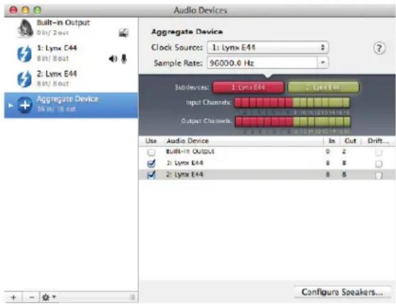
An Aggregate Device is created from Applications > Utilities > Audio MIDI Setup in OS X. Make sure that the Audio Window is open. Click the “+” button at the bottom of the window to create a new aggregate device. You can name it whatever you wish, or accept the default name. Click to check each of the Lynx Interfaces that you wish to be combined into this aggregate device. Up to four interfaces can be added. Make sure that the Drift or Resample box is Un-Checked for each selected interface. Now, your multi interface Aggregate Device
is ready to use from within your favorite Audio application (Make sure to select “Aggregate Device” as your active device in the Audio Devices settings of your app).
8.2 Application Setup
The E22 and E44 were designed to provide maximum compatibility with the most popular audio and multimedia applications that use the Windows MME, DirectSound, ASIO and OS X Core Audio driver standards. It is crucial that the applications are set up correctly for optimal operation.
8.2.1 Windows
The Windows drivers for the E22/E44 support two dominant driver models, WDM (which include MME/DirectSound/WASAPI) and ASIO.
WDM was developed by Microsoft and is used most typically by media playback applications, such as Windows Media Player, iTunes, Spotify, etc.
ASIO (Audio Streaming Input/Output) was developed by Steinberg, and was designed to address the low-latency and high channel count needs of Pro Audio and Music Production. ASIO is an option for Audio Production applications such as Pro Tools, Cubase/Nuendo, Sonar, Samplitude/Sequoia, Audition, etc. These applications may also support WASAPI or
DirectSound, but when the option exists, we recommend using ASIO for the best performance.
8.2.1.1 WDM/Multimedia Applications
The Lynx cards can be used as playback devices for most popular multimedia, home theater and consumer audio applications. Some such applications allow selection of specific playback devices. In these cases, a Lynx output device can be selected from the appropriate device selection menu. When output device selection is not an option, it can be assumed that the application uses the Windows default audio device. To use the desired output as the system default:
With Windows 7 /Windows 8 navigate to:
Start > Control Panel > Sound > Playback. Right-Click the desired Lynx output device and choose “Set as default device”. Note: With multiple cards, the device IDs can be misrepresented here. See Section 8.14: Configure for use.
With an E22, two stereo WDM play and record devices will appear to the operating system, four stereo devices with an E44. Play devices are labeled as eXX Speakers (this is equivalent to Play 1+2), eXX Play 3+4, eXX Record 1+2, eXX Record 3+4, etc. Play channels are pre-routed by default. Play 1+2 is routed to Analog Output 1+2, Play 3+4 is routed to Analog Output 3+4 on an E44, and Digital Out Left/Right with an E22. With an E44, play 5-8 are assigned to the Digital Outputs.
As an example, if you wish to have a multimedia/WDM application stream to the E22 Digital Output, you would choose Play 3+4 as the output device. If the software did not allow device selection and only used the Windows default play device, then you would set the Windows Default in the Sound Section of Control Panel to Play 3+4.
8.2.1.2 ASIO Applications
When using an application that supports the ASIO driver standard, one must specify the Lynx ASIO driver as the active audio device from within the audio software. Once that is established, multiple stereo input and output devices will be available for use within the application. Like with WDM, an E22 will present two stereo driver devices, an E44 will present 4.
When using an ASIO compatible program, the appropriate ASIO device must be selected from a settings or options menu in the application. The correct choice would be “Lynx ASIO”.
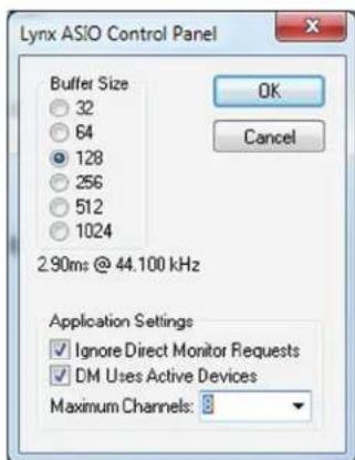
Many ASIO applications provide access to an ASIO Control Panel for the device being used. If present, this button will launch the Lynx ASIO Control Panel.
From this panel, the ASIO buffer size and system latency can be established conveniently within the audio software application.
The following parameters can be altered from the Lynx ASIO Control Panel:
-
Buffer Size - This control allows the size of the ASIO buffer in samples to be established. The buffer size is the primary factor in the amount of latency that a user will experience when using the Lynx card. See Section 8.2.1.4 Controlling Latency by Changing the Buffer Size
-
Latency - Displays the amount of latency in milliseconds that is the result of the selected buffer size at the active sample rate.
-
Ignore Direct Monitor Requests - This switch causes the Lynx driver to disregard Direct Monitor commands from an ASIO software application. Since Direct Monitor calls can assign and mute monitor sources in the Lynx Mixer, setting this parameter to "ON", can prevent mixer settings from being changed when an ASIO application is launched.
-
DM Uses Active Devices - This switch sets the Direct Monitoring scheme for the application. When unchecked, all devices (active or not) may be used for Direct Monitoring. When checked, only active devices, or devices assigned to software busses, are used for Direct Monitoring. This gets around a problem where Cubase & Nuendo might select the wrong Direct Monitoring input or output if non-contiguous devices are active. This switch is ON by default for most ASIO applications.
-
Maximum Channels – This switch determines how many ASIO device channels will be available to the application. This is an application specific parameter. If different ASIO applications are used at different times, it is possible to have them set differently.
The primary purpose for this switch is to increase CPU efficiency and to facilitate multi-client operation. The default state is “unlimited”, which means that as many Lynx channels are presented to the Operating System, a corresponding number of ASIO devices will appear to the software. For instance, if one has 3 E44 cards installed, then 24 ASIO channels will be presented to the audio software.
Most audio software allows the user to specify how many ASIO devices are used, generally in a settings or options menu. There are some applications however that grab control over ALL of the ASIO devices in the system. This can be problematic because it uses more CPU power than is necessary, and also because there are no driver devices available to be used by another application (multi-client operation).
In these cases, setting the MAXIMUM CHANNELS switch to the desired number of channels, frees up some CPU overhead, and allows another application to access the channels that the ASIO application is not using.
Latency in an audio interface can be defined as the time required to process a sample from an application to the interface's audio output. A number of factors determine the achievable latency performance of a Lynx card: processor speed, operating system, sample rate, number of utilized record or play channels, system efficiency, etc.
Latency can be manipulated by changing the size of the buffers used to transfer data to and from the E22/E44. The higher the buffer size, the less work the computer has to do to stream audio to the hardware. However, a higher buffer results in more latency. Also, the higher the sample rate, the higher the buffer size needs to be. For instance, a buffer size of 128 samples at a sample rate of 44.1kHz results in 2.9 milliseconds of latency. However, at 96kHz, a buffer size of 128 = 1.33 milliseconds. Therefore the buffer size needs to be increased as the sample rate increases to maintain the same level of performance. If the buffer size is too low, you can experience clicks, pops or distortion in the audio. This is the result of buffer under-runs, when the audio buffer is momentarily depleted because the computer cannot deliver samples quickly enough to keep it filled.
Why is latency important? It isn't in every case. Here are the main conditions where low latency is important:
* Software input monitoring. This is where you are monitoring through your audio software the input signals to be recorded. The software is re-directing the input signal back out to a play device. If the buffer is too high here the performer will hear a noticeable delay between the notes they are playing and hearing the sound back through the computer. Note that with the E22/E44, zero latency hardware monitoring is available as an alternative to software monitoring. See Section 7: Lynx Mixer Application Reference.
* Virtual Instruments. Generally this would involve using a software synthesizer or other virtual sound source as an alternative to dedicated hardware like a keyboard or tone module. Frequently one would play these instruments with some sort of MIDI controller. The delay between a key being struck and hearing the resulting note from the virtual instrument is a function of latency.
* Mix Automation. Virtually all DAW applications feature some sort of Mix Automation, and most allow an external Mix surface or MIDI controller to facilitate mixing within the software environment. Whether using onscreen faders or a MIDI surface of some sort, latency will determine the delay between manipulating a fader or knob, and that move being reflected in the project.
8.2.2 Macintosh OS X
The E22/E44 will operate as a Core Audio device under OS X. Core Audio is the dominant audio driver model for OS X, and is used for media playback applications as well as Pro Audio applications.
8.2.2.1 OS X Audio Applications
The Lynx cards can be used as playback devices for most popular multimedia, home theater and pro audio applications. Some such applications allow selection of specific playback devices. In these cases, an E22/E44 output device can be selected from the appropriate device selection menu.
In cases where the playback software does not provide access to output selections, the default output devices for the operating system will be used. In OS X, the audio out default device can be established from Applications > Utilities > Audio MIDI Setup.
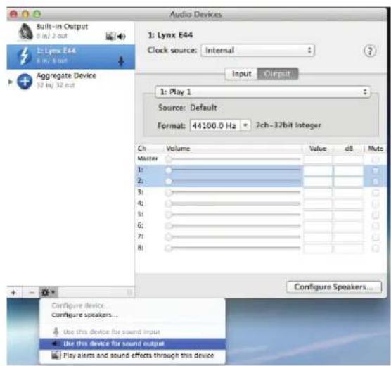
When the Lynx card is selected as the output sound device, channels 1&2 are active by default. To change this, highlight the Lynx card, choose “configure speakers” from the gear icon, and then select the desired stereo output channels from the drop-down menus.
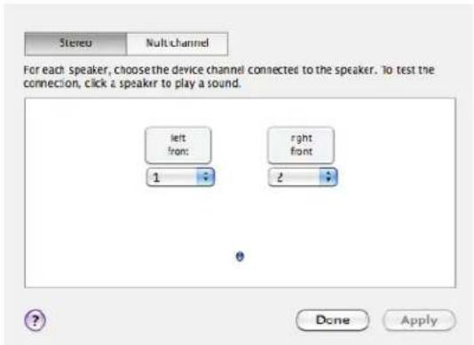
8.2.2.2 Controlling Latency by Changing the Buffer Size
Latency in an audio interface can be defined as the time required to process a sample from an application to the interface's audio output. A number of factors determine the achievable latency performance of an E22/E44 system: processor speed, operating system, sample rate, number of utilized record or play channels, system efficiency, etc.
Latency can be manipulated by changing the size of the buffers used to transfer data to and from the card. Core Audio buffer size controls are offered within most pro audio recording applications. With the E22/E44, buffer sizes typically range between 32 and 2048 samples.
Smaller buffer sizes will give you lower latency. However, if a buffer size is too small for the system or context, audio anomalies such as clicks and pops may occur. It is recommended to become familiar with altering the Lynx buffer size to best suit the context of use.
Once you determine the lowest achievable buffer size, you will typically have to double the size each time you double the sample rate, but the effective latency will remain constant. For example, if a system is capable of operating at a buffer size of 128 samples at 48 kHz, then for a 96 kHz project, the buffer size will likely need to be increased to 256 samples.
8.3 Onboard Variable Trim Pots
The E22/E44 cards have Trim pots right on the circuit board, for calibrating the analog I/O to match the trim settings of external gear, or to set the card to a studio reference other than the factory default of 20dBu. The trim pots are located behind the 25-pin D-Sub port on the component side of the board, and provide the ability to independently adjust trim the level of all analog input and analog output channels continuously over a wide range. The trim level of each channel is controlled by a 25-turn trim pot which provides a range of +8.5 dBu to +24 dBu full-scale (4 to 20 dB headroom above a +4 dBu nominal level).
The trim pots are accessed by removing the side of the computer. Access will vary by motherboard location and chassis design. The pots are staggered for access. Use a very small flathead screwdriver, and insert at an angle for easiest access.
The location of the trim pots for each channel is shown in the image below.
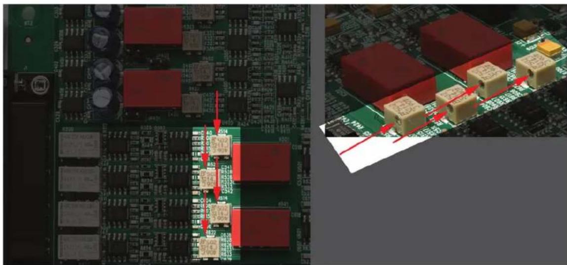
From the top of the board going downward, the channel associated with each pot is:
Analog In 1
Analog In 2
Analog In 3
Analog In 4
Analog Out 1
Analog Out 2
Analog Out 3
Analog Out 4
For the input channels, a clockwise rotation of the trimpot corresponds to a decrease in allowable input level (increased sensitivity). For the output channels, a clockwise rotation of the trim pot corresponds to an increase in output level.
To set Input Trim levels, send reference tones to the input and calibrate with the meters in the Lynx Mixer, or some other accurate software reference meter.
For outputs, generate tones from within a computer application and measure the level from an outboard metering device.
⚠️ Please note: Take care when adjusting the trim pots, with too much force the plastic housing can be damaged.
8.4 Updating Firmware
The E22/E44 contains firmware that is field-programmable. These updates can improve performance and enhance functionality of the card.
To program the Lynx card's firmware, follow these steps:
- Visit www.lynxstudio.com > Support > Downloads. Product = E22/E44.
- Download file. Make sure all audio and non-essential software is closed
- Run the updater, accept defaults
- From the Welcome screen, verify that the new firmware version is more current than the current firmware on the card. If so, press “Program” to continue
- When the updater is complete, power down the computer when prompted.
- After a few seconds, turn the computer back on. The firmware should now be up-to-date. You can verify the firmware revision from the Lynx Mixer > About Lynx Mixer.
We encourage users to read the “Release Notes” for each firmware updater before running it, just to insure that changes made are pertinent to your conditions of use. For instance, sometimes there are firmware updates for specific operating systems or contexts of use. In such a case, there is no point in updating unless you require those features.
On rare occasions a firmware update may fail. Depending on when in the process this occurs, it's possible that a failed firmware update may render the card unusable. Fortunately the Lynx cards were designed with a quick fix. The card actually has two PROMs, and only one of them is programmable. The other contains the factory firmware and cannot be field programmed. Switching from prom 2 (the default, programmable prom) and Prom 1 (the factory prom) will bring the card back to life and allow another chance to update the firmware. Here are the steps to use Prom 1 to recover from a failed update attempt:
- Turn off and unplug the computer and remove the E22/E44 card.
- On the Component side of the board, towards the back, there is a set of four switches. Switches 3 and 4 control the Prom selection.
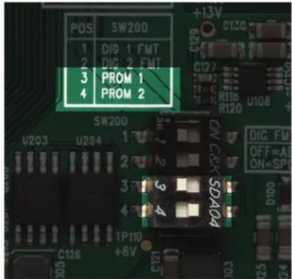
- By default switch 4 is labeled "Prom 2" and is ON be default. Switch 3 is labeled Prom 1 and is OFF by default. Simply turn switch 4 to the OFF position, and switch 3 to the ON position. In other words, prom 2 is OFF and Prom 1 is ON.
- Return the card to its slot, plug in and turn on the computer.
- If the OS now recognizes the card, run the latest firmware updater for the card
- When complete, shut down computer.
- Remove the AC cord, remove the card, and set the switches back to their original position. Prom 2 is ON, and Prom 1 is OFF.
- Reinstall the card and boot into the OS. The card should now operate with the current firmware.
If the card still is not seen with the jumper on Prom 1, there is either a problem with the card or the computer's PCIe slot. Contact Lynx Technical Support.
8.5 Volume Control Settings Application (Windows Only)
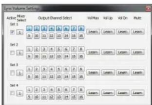
This program allows control of the Lynx Mixer Master Output Volumes from the computer keyboard, regardless of which application is currently running in the foreground. It is not required for the Lynx Mixer to be open for the Volume Control Settings program to function.
To launch this program, right-click on the Lynx Tray Volume icon in the taskbar and select "Volume Control Settings...". With this program, it is possible to program custom key combinations that control mixer volume functions. When the driver is first loaded, no default key values are programmed. You must manually have the program learn which key sequence you wish to control Volume Max, Volume Up, Volume Down and Mute. To do this, Activate the first key sequence group by clicking the "Active" check box on the first row. Next, select which master output volumes you wish to use. This app works for all Lynx cards, so 16 channels are displayed. For the E44, simply ignore channels 9-16, and for the E22 ignore channels 5-16. Shift-click allows selection of two adjacent channels and Ctrl-click selects all 16 channels. Press the "Learn" button for the first volume command that you wish to program, and then press the key sequence you want to control that volume function. The key combination will be confirmed in the "Assigned Key:" box. Close the program once the key sequences you require have been learned.
You may quickly launch the Lynx Mixer application by double clicking the left mouse button on the Lynx Tray Volume icon.
PLEASE NOTE: It is possible to program a key sequence that already has a meaning for the operating system or for a specific application. In this case, Windows will only send these commands to the Volume Control Settings program, and the key sequence will no longer function for the other application(s). We suggest programming key combinations that utilize Shift and Ctrl keys to minimize the likelihood of accidentally using a sequence that is meaningful to some other application. For instance: CTRL + SHIFT + UP ARROW for
Volume up, CTRL + SHIFT + M for Mute, etc. If you encounter a problem, simply have the Volume Control Settings app learn a new key sequence.
8.6 Connector Pinouts
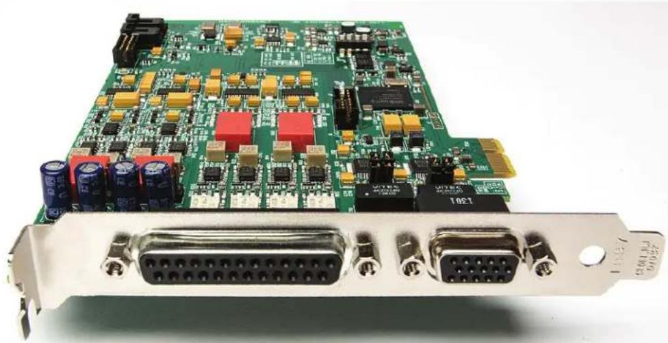
natural_image
Close-up of a green printed circuit board with multiple electronic components and two D-subdual transceivers (no visible text or symbols)The E22 and E44 cards have two external ports for connecting cables to audio equipment, as well as internal clock connections. The pinouts below are presented as a convenience should one wish to use custom cables, rather than the Lynx branded options.
8.6.1 Audio Port
The Audio Port is a female 25-pin D-connector with the following connections:
| Pin Signal | Pin Signal | ||
| 1 OUT | 4 Ho t | 14 OUT | 4 Cold |
| 2 OUT 4 | Gn d | 15 IN 4 Hot | |
| 3 | I N | 4 | C |
| 4 OUT 3 | Ho t | 17 OUT | 3 Cold |
| 5 OUT 3 | Gn d | 18 IN 3 Hot | |
| 6 | I N | 3 | C |
| 7 OUT 2 | Ho t | 20 OUT | 2 Cold |
| 8 OUT 2 | Gn d | 21 IN 2 Hot | |
| 9 | I N | 2 | C |
| 10 OUT | Ho t | 23 OUT | Cold |
| 11 OUT | Gn d | 24 | IN 1 Hot |
| 12 IN 1 | Cold 25 IN 1 Gnd | ||
| 13 | none | ||
| o | 1 | d | 16 IN |
| o | 1 | d | 19 IN |
| o | 1 | d | 22 IN |
Please note: for the E22 card, only In 1+2 and Out 1+2 are active. The other pins are not utilized.
8.6.2 Sync Port
The Sync Port is a female, high-density 15-pin D-connector with the following connections:
| Pin | Signal | Pin | Signal |
| 1 | none | 9 | Digital Out 1 Hot |
| 2 | none | 10 | Digital In 1 Cold |
| 3 | Digital In 2 Hot | 11 | none |
| 4 | Clock In Hot | 12 | none |
| 5 | Digital In 1 Hot | 13 | Digital Out 2 Hot |
| 6 | Ground | 14 | Clock Out Hot |
| 7 | Digital Out 2 Cold | 15 | Digital Out 1 Cold |
| 8 | Digital In 2 Cold | Shell | Ground |
Please note: for the E22 card, there is no Digital In 2 or Digital Out 2. Those pins are not utilized.
8.6.3 Header Connectors
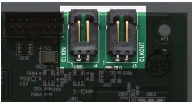
natural_image
Close-up of a green printed circuit board with two black connectors and labeled pins (no readable text beyond component labels)The LStream 2 port is a 14 pin header shrouded in black plastic labeled CLKIN and CLKOUT.
Each are two-pin headers shrouded in black plastic. For both connectors, Pin 1 carries the clock signal and Pin 2 is a ground signal. Pin 1 is located on the left side of each connector when viewing the component side of the board.
9 Specifications
Analog I/O
Lynx E44 Four input channels / four outputs channels
Lynx E22 Two input channels / two output channels
Type
Electronically
balanced
or unbalanced, XLR connectors
Level +20dBu full-scale or variable +8.23dBu to +24dBu full-scale; jumper selectable
Input Impedance Balanced mode: 24 kΩ
Unbalanced mode: 12 kΩ
Output Impedance Balanced mode: 100 Ω
Unbalanced mode: 50 Ω
Output Drive Capability 600 impedance, 0.2 μF capacitance
A/D and D/A Type 24-bit, multi-level, delta-sigma
Sample Rates All standard sample rates up to 192kHz
Analog In Performance
(Analog performance specs measured at 44.1 kHz sample rate, 24-bit, card installed in computer)
Frequency Response 20 - 20 kHz, ± 0.05 dB
Dynamic Range 117 dB, A-wtd.
Channel Crosstalk <-120 dB, 1kHz signal@-1dBFS
THD+N -111 dB (0.0003%) @ -1 dBFS
1 kHz signal, 22Hz - 22kHz BW
Analog Out Performance
(Analog performance specs measured at 44.1 kHz sample rate, 24-bit, card installed in computer)
Frequency Response 20 - 20 kHz, ± 0.05 dB
Dynamic Range 120 dB, A-wtd.
Channel Crosstalk <-120 dB, 1kHz signal @ -1dBFS
THD+N -108 dB (0.0004%) @ -1 dBFS
1kHz signal, 22Hz - 22kHz BW
Digital I/O
Number / Type
Lynx E44
Four input channels / four outputs channels
Lynx E22
Two input channels / two output channels
24 bit AES/EBU or S/P DIF format jumper selectable, transformer coupled, XLR connectors
Sample Rates 44.1 kHz, 48 kHz, 88.2 kHz, 96 kHz, 176.4 kHz, 192 kHz
Clock I/O
Number
External: one input and output, BNC connectors on Sync Cable
Internal: one input and output on board-mounted headers
Level / Impedance TTL / 75 Ω
Type
Word clock
On-board Digital Mixer
Channel Capacity
16 input channels, 8 sub outputs
Monitor Mixing 16 x 8 with no limitations
Metering
Peak levels to -120 dB on all inputs and outputs
Connections
Audio Port Bracket-mounted 25-pin female D-sub connector for analog audio In/Out
Sync Port Bracket-mounted 15-pin high-density female D-sub connector for digital input and output, word clock in and out
Cables (Optional)
| E44 Audio Cable | 25-pin male D-sub to 4 male and 4 female XLR connectors on six-foot shielded twisted pair cabling (part # CBL-L2Audio-A) |
| E44 Sync | 15-pin high-density male D-sub to (2) male and (2) female XLR on six-foot shielded twisted pair cabling and (2) female BNC connectors on six-foot 75 ohm coaxial cabling (part # CBL-ESYNC) |
| E22 Audio Cable | 25-pin male D-sub to 2 male and 2 female XLR connectors on six-foot shielded twisted pair cabling (part # CBL-L22Audio) |
| E22 Sync | 15-pin high-density male D-sub to (1) male and (1) female XLR on six-foot shielded twisted pair cabling and (2) female BNC connectors on six-foot 75 ohm coaxial cabling (part # CBL-L22Sync) |
Software
Windows Drivers Windows 7 / 8: MME / DirectSound / WASAPI (WaveRT); ASIO 2.3
Macintosh Drivers Core Audio for OS X 10.8 and higher.
Lynx Mixer Application Provides complete control of digital mixer and all hardware settings.
General
PCI Express Bus 1x
Data Transfers Highly efficient Lynx V2 DMA engine; bus mastering
Power +3.3V @ 630 mA, +12V @ 500 mA
Size 5.0" H X 7.4" W X 0.75" D (half-size PCI Express card)
Shipping Weight 1 pound
Certifications CE and FCC Class B
RoHS
Certified
10 Troubleshooting
The E22/E44 does not show up in the Operating System as a usable device:
- Verify that the card has been installed correctly and is securely seated in the slot. You may also want to try installing the card into a different slot.
- Verify that you are using a compatible Operating System. See Section 2.2: Operational requirements
- With a proper installation, the LED on the back edge of the board can give diagnostic information. There are four possible states for this LED:
LED Bright: Card is functioning and driver is successfully installed
LED DIM: Firmware is not functioning. Reprogramming firmware or setting card to PROM 1 are suggested troubleshooting steps. See Section 8.4: Updating Firmware
LED Flashing: This indicates that the driver has not been properly loaded. Try reinstalling driver, installing a different driver version (downloaded from the Lynx website), or investigating if there is a conflict with another piece of hardware in the system. Also, consider moving the card to a different PCIe slot if one is available.
LED Out: This means the card is NOT appearing to the OS. Try installing in a different PCIe slot. Also try setting the Jumper for Prom 1 (See Section 8.4: Updating Firmware). If all attempts are unsuccessful, try installing into a different computer and see if the card appears after loading the driver.
The card shows up in the Operating System as a usable device, but will not pass audio:
- Make sure that the E22/E44 has been assigned as the active device in the application being tested. Many audio applications allow a specific audio device to be selected from a configuration menu. Other applications will use whatever the operating system default device is. In this case verify that the E22/E44 has been configured as the default playback device for the system.
- Check the Lynx Mixer Outputs Panel and see if there is meter activity for the appropriate outputs being used. If there is, check the cable connections from the card's outputs to the monitoring equipment.
- Click "Restore Defaults" in the Lynx Mixer from the MIXER menu.
Continuous clicking, popping or crackling noises in your audio:
- Check clock master settings. In any digital audio configuration, there can be one, and only one master clock. All other digital audio devices must be configured as slaves to the designated master clock. Since the Lynx's SynchroLock™ technology provides an extremely stable and jitter-resistant clock, we recommend setting the card as the master clock in your digital audio system. With multiple cards in a system, either all should slave to external sources, or one card should be on Internal, the rest should be clock slaves (Header). See Section 8.1: Configuring multiple cards
- Check buffer settings in your audio application software. Smaller buffer sizes are preferred because they reduce latency (the time it takes for an audio signal to travel through your audio software). In some cases, however, setting too small a buffer size can overtax your computer's processor, particularly when running multiple tracks and/or a number of DSP plug-ins. This can result in clicks and pops and other distortion in your
audio playback. Try increasing the buffer size from within the audio application or via the ASIO control panel and see if your playback performance improves.
- Disable Wi-Fi, Bluetooth, or other background devices that maybe be draining the CPU performance.
Audio stops suddenly during playback or recording, or there are dropouts
- Many new Operating Systems utilize very aggressive power management routines that can disrupt real-time audio performance.
For Mac OS X users, in the Lynx Mixer from Settings > Advanced, there is an option to "Disable CPU Power Management". Make sure that is Checked (selected).
For Windows users, there are other settings that help cam significantly reduce these power management mechanisms.
- In the Windows Control Panel > Power Options, set the Power Plan to “High Performance”
-
In the computer BIOS, disable CPU Speedstep (sometimes labelled as EIST, or Intel Speedstep)
• In the computer BIOS, disable C States (sometimes split out as C1, C3, C6, etc.) -
If this behavior happens after pausing a multimedia playback app with Windows, make sure that you are using driver build 22 or above.
-
Make sure there are not any background tasks that are causing the behavior, such as antivirus software, scheduled tasks, or automatic updates.
There is no signal from the Digital Inputs or Digital Outputs
- Make sure that the format for the digital I/O matches the format of the connect device.
The E22/E44 digital I/O can be set to AES or SPDIF. See Section 5.1: Hardware Installation - On an E22 the Digital Output defaults to Lynx Play 3+4 as the selection in your audio software. The Digital Input is Record 3+4. On an E44, the Digital Outputs are Play 5-8, and the Digital Inputs are Record 5-8. Make sure that the correct device is selected in your audio software for input or output
- Make sure that the external digital device is powered up and cables from the Lynx card are connected into the correct ports (i.e. Lynx “Out” to Device’s “In”, and vice versa).
The Sample rate in the Lynx Mixer does not match the sample rate of the audio material being played:
If the card is operating on “Internal” as a CLOCK SOURCE, you must manually select the rate through either the audio application settings page, or globally through the OS’s sound control settings. With “External” (word clock) or “Digital In” clocking you must also set the sample rate to the desired rate on the clock master device. Otherwise, the playback streams may be sample rate converted by the operating system, compromising playback quality.
Please see Section 5.4: Clock Settings and Connections for more information.
If the card is operating on Internal, and there is a sample rate discrepancy, check the OS default sample rate and see if that is where the discrepancy exists. In Windows, this can be
established in the Sound Section of Control Panel, after selecting a device click Properties > Advanced > Default Format. In OS X, this would be established from Utilities > Audio MIDI Setup. Select the device and then the sample rate in the right pane.
Also, check in the Lynx Mixer and make sure that Rate Lock from the Adapter page is NOT selected.
11 Support
We are devoted to making your experience with the E22/E44 trouble-free and productive. If the troubleshooting and operational sections of this manual did not help resolve your questions, several support options are available to you:
11.1 Lynx Website Support Resources
Logging on to www.lynxstudio.com > support will provide several options for resolving your support issues:
Support Ticket
For direct attention from the Lynx Technical Support Staff, registered users can submit a support ticket online that details their problem and steps they've taken to resolve it. Most Support Ticket submissions are responded to within 24 hours.
Frequently Asked Questions
An extensive catalog of FAQs derived directly from our most common tech support inquiries. Our FAQ section is updated regularly and designed to allow users to find the answers to their most common questions quickly.
Firmware and Driver Downloads
A library of current firmware and driver files is available for download and installation. Check back regularly to insure that your Lynx Card is up-to-date.
Lynx Support Forum
An online support forum provides a venue for Lynx customers to post questions and issues, and receive responses from other users as well as Lynx technical administrators. Searching previous posts is often an excellent way to uncover valuable information about Aurora operation and troubleshooting. See http://www.lynxstudio.com/forum
11.2 Telephone Support
Complimentary telephone support is available by calling +1 (714) 545-4700 extension 206 from 9AM to 5PM Pacific Time, Monday through Friday, excluding United States Holidays.
11.3 Registering your E44/E22
Lynx is committed to providing you with the best service possible. To help us serve you better, please be sure to register your E22/E44.
Register on the web at: www.lynxstudio.com > support > Register Your Products. Once you are registered you will automatically receive notifications of new products and upgrades.
11.4 Return Policy
If you have a unit that you suspect is defective or is malfunctioning, contact Lynx technical support via one of the means described above for diagnosis. If the technician determines that the unit is faulty, they will issue an RMA number so you can send the unit in for repair. Units received without a valid RMA number will be refused. All RMA numbers are valid for 30 days from the date of issue.
11.5 Locating the Serial Number of Your E44/E22
To register your Lynx card, you must supply its serial number. The serial number is located beneath the barcode on the underside of the card, and on the shipping carton.
12 Warranty Information
One year Free Labor / One year Parts Exchange This product must be returned to the factory for repair.
Who Is Covered?
You must have proof of purchase to receive warranty service. A sales receipt or other document showing when and where you purchased the product is considered proof of purchase. This warranty is enforceable only by the original retail purchaser. To be protected by this warranty, the purchaser must complete and return the enclosed warranty card or register online within 14 days of purchase.
What Is Covered?
Warranty coverage beings the day you buy your product. For one year thereafter, Lynx shall, at its sole and absolute option, either repair or replace free of charge any product that proves to be defective on inspection by Lynx or its authorized service representative. In all cases disputes concerning this warranty shall be resolved as prescribed by law. All parts, including repaired and replaced parts, are covered only for the original warranty period. When the warranty on the product expires, the warranty on all replaced and repaired parts also expires.
What Is Excluded?
You warranty does not cover:
- Labor charges for installation or setup of the product.
- Product repair and/or part replacement because of misuse, accident, unauthorized repair or other cause not within the control of Lynx.
- A product that requires modification or adaptation to enable it to operate in any country other than the country for which it was designed, manufactured, approved and/or authorized, or repair of products damaged by these modifications.
- Incidental or consequential damages result from the product, damage to property, damage based on inconvenience or on loss of use of the product, and, to the extent permitted by law, damages for personal injury. Some states do not allow the exclusion or limitation of incidental or consequential damages, so the above limitation or exclusion may not apply to you.
- A product that is used for rental purposes.
To Get Warranty Service...
To obtain warranty service, the purchaser must first call or email Lynx at the email address or telephone number printed in Section 0 to obtain a Return Authorization Number and instructions concerning where to return the unit for service. All inquiries must be accompanied by a description of the problem. All authorized returns must be sent to Lynx or an authorized Lynx repair facility postage prepaid insured and properly packaged. Proof of purchase must be presented in the form of a bill of sale, canceled check or some other positive proof that the product is within the warranty period. Lynx reserves the right to update any unit returned for repair. Lynx reserves the right to change or improve design of the product at any time without prior notice.
Lynx Studio Technology and the Lynx Logo, E22 and E44 Logo are all trademarks of Lynx Studio Technology, Inc. All other product or company names are the trademarks or registered trademarks of their respective owners.
E44/E22 ^TM User Manual, April 11, 2016.
Copyright © 1998-2016 Lynx Studio Technology, Inc. All rights reserved.

- LYNX E22/E44
- User Manual
- Table of Contents
- Introduction....4
- Before you begin....6
- Nomenclature Used in this manual....7
- Warranty Registration....7
- Installation Procedures....8
- Getting Started ....16
- Lynx Mixer Application Reference 20
- Using the E22/E44 36
- Introduction
- Overview
- Features
- Before you begin
- In the box
- Operational requirements
- Windows
- Macintosh
- Nomenclature Used in this manual
- Warranty Registration
- Installation Procedures
- Hardware Installation
- Installing the Lynx Driver
- Windows 7 (32-bit or 64-bit) or Windows 8
- OS X
- Cable Connections
- Clock Settings and Connections
- External Clock
- Digital In
- Multiple Lynx cards
- Audio Devices
- Device Order
- Verifying Successful Installation
- Getting Started
- Windows Quick Audio Test
- Macintosh Quick Audio Test
- Lynx Mixer Application Reference
- Starting the Lynx Mixer Application within Windows
- Starting Lynx Mixer Application within OS X
- General Operation
- Navigation Bar
- ① Open Scene
- Save Scene
- ③ Rate Select
- Adapter
- Record
- ⑥ Play
- Adapter Section
- ① Current Source
- ② Measured Rate
- ③ Rate Lock
- SynchroLock
- Preferred Clock Source
- Analog Trims
- Record Section
- ① Input Source selection
- Pan Pot
- Numeric Level Indicator
- Faders and Meters
- ⑤ Mutes
- Channel Link
- Record Source Label
- Play Section
- ① Pan Pot
- Numeric Level Indicator
- Faders
- Mutes
- ⑤ Channel Link
- Play Channel Label
- Outputs Section
- ① Numeric Level Indicator
- ② Faders and Meters
- Mutes
- Channel Link
- ⑤ Output Button
- Mixer Menu
- ① Restore Defaults
- ② Open Scene
- ③ Save Scene
- About
- Settings Menu
- Settings > Advanced Menu
- Adapter Settings
- ② Driver Options (Windows only)
- Record Dither Type
- Allow Clock Change If Active
- Performance Buffers (OS X Only)
- ⑤ Mixer Lock
- Using the E22/E44
- Configuring multiple cards
- Establish clock connections
- Card as Master
- Cards as clock slaves
- Setting device order
- Setting clock sources in the Lynx Mixer
- Configure for use (Windows)
- Configure for Use (OS X)
- Application Setup
- Windows
- WDM/Multimedia Applications
- ASIO Applications
- Macintosh OS X
- OS X Audio Applications
- Controlling Latency by Changing the Buffer Size
- Onboard Variable Trim Pots
- Updating Firmware
- Volume Control Settings Application (Windows Only)
- Connector Pinouts
- Audio Port
- Sync Port
- Header Connectors
- Specifications
- Analog I/O
- Analog In Performance
- Analog Out Performance
- Digital I/O
- Clock I/O
- On-board Digital Mixer
- Connections
- Software
- General
- Troubleshooting
- The E22/E44 does not show up in the Operating System as a usable device:
- The card shows up in the Operating System as a usable device, but will not pass audio:
- Continuous clicking, popping or crackling noises in your audio:
- Audio stops suddenly during playback or recording, or there are dropouts
- There is no signal from the Digital Inputs or Digital Outputs
- The Sample rate in the Lynx Mixer does not match the sample rate of the audio material being played:
- Support
- Lynx Website Support Resources
- Support Ticket
- Frequently Asked Questions
- Firmware and Driver Downloads
- Lynx Support Forum
- Telephone Support
- Registering your E44/E22
- Return Policy
- Locating the Serial Number of Your E44/E22
- Warranty Information
- Who Is Covered?
- What Is Covered?
- What Is Excluded?
- To Get Warranty Service...
Brand : LYNX
Model : E22
Category : Hi-Fi System