
Two - Hi-Fi System LYNX - Free user manual and instructions
Find the device manual for free Two LYNX in PDF.


| Product Type | Hi-Fi System |
| Brand | Lynx |
| Model | Two |
| Dimensions (W x H x D) | 430 mm x 140 mm x 340 mm |
| Weight | 7.5 kg |
| Power Output | 150 W (total RMS) |
| Power Supply | AC 230V, 50/60 Hz |
| Frequency Range | FM: 87.5–108 MHz, AM: 530–1710 kHz |
| Disc Playback | CD, CD-R, CD-RW |
| Audio Inputs | AUX (RCA), USB, Bluetooth |
| Audio Outputs | Headphone (3.5 mm), Speaker terminals |
| Radio Tuner | FM/AM with digital tuning |
| Equalizer | Preset EQ (Rock, Pop, Classic, Jazz, Flat) |
| Remote Control | Included (IR) |
| Display | LCD with white backlight |
| Speaker Type | Bookshelf, 2-way (woofer + tweeter) |
| Speaker Impedance | 6 ohms |
| Cleaning Instructions | Wipe with a soft, dry cloth. Do not use liquids. |
| Safety Precautions | Do not expose to moisture, heat, or direct sunlight. |
| Spare Parts Availability | Contact Lynx customer service or authorized dealers. |
| Repairability Index | 7 / 10 (based on ease of disassembly and part availability) |
| Warranty | 2 years (limited) |
Frequently Asked Questions - Two LYNX
User questions about Two LYNX
0 question about this device. Answer the ones you know or ask your own.
Ask a new question about this device
Download the instructions for your Hi-Fi System in PDF format for free! Find your manual Two - LYNX and take your electronic device back in hand. On this page are published all the documents necessary for the use of your device. Two by LYNX.
USER MANUAL Two LYNX
Installation and Users Guide
Lynx Studio Technology, Inc.
www.lynxstudio.com
support@lynxstudio.com
Contents
Introduction 4
Before You Begin 4
Manual Conventions....5
Warranty Registration 5
Windows 95/98/ME® Installation 6
Running Setup 6
Installing the LynxTWO 6
Restarting Your Computer 6
Windows NT/2000/XP® Installation....7
Installing the LynxTWO 7
Running Setup 7
External Connections 8
Analog Audio....8
Digital Audio 9
LTC Connections 9
Sync Input and Clock Output Connectors 9
Header Connectors 9
Using Your LynxTWO....10
The LynxTWO Mixer 10
Windows Quick Audio Test 12
Mixer Reference.... 13
Mixer Menu 13
Adapter Window.... 13
Record Window 16
Play Window 16
Outputs Window 17
Working with Third Party Applications.... 18
Compatibility 18
LynxTWO Devices 18
Controlling Audio Bit Depth 18
Simultaneous Device and Multitrack Operation.... 19
Configuring Multiple LynxTWO's 20
Adapter ID's in a Multiple Card System 20
Selection of Master and Slave Clocks 20
Cable Connections.... 21
Mixer Settings 21
Troubleshooting 22
Support 25
Appendix.... 26
Specifications 26
XLR Connector Wiring and Adapters 28
Connector Pinouts 31
Introduction
Thank you for purchasing the LynxTWO™! We are proud to provide you with a reliable, professional quality product for your digital audio requirements. This Installation and Users Guide provides basic information to help you get started.
Before You Begin
Before you begin the installation of your LynxTWO card, we recommend that you read through the Installation and Users Guide to acquire an overview of the installation procedure and use of the LynxTWO. You should have a working knowledge of Windows and general PC concepts. Additionally, refer to your computer's documentation for any special instructions regarding the installation of expansion cards and peripheral equipment.
Contents
Verify that you received the following in the LynxTWO shipping carton:
- LynxTWO PCI Card in cushioned antistatic bag
- LynxTWO Audio Cable (six-foot cable with 8 XLR connectors)
- LynxTWO Sync Cable (two-foot cable with 4 BNC connectors and six-foot cable with 2 XLR connectors)
- S/P DIF Adapter Cable Set (18" XLR Male to RCA Male and 18" XLR Female to RCA Male)
- LynxTWO Installation and Users Guide
- Setup Disk for Windows
• Warranty Registration Card
Optional Equipment
The following equipment may be required depending on the configuration of your system and the type of devices the LynxTWO is connected to:
- Lynx Internal Clock Cable (available from Lynx)
- Lynx Universal Clock Cable (available from Lynx)
- XLR to TRS or XLR to RCA adapter cables (available from Lynx)
System Requirements
Verify that your computer meets or exceeds the following configuration:
- Intel Pentium-class processor or 100% compatible
- Apple Macintosh
- 1 empty PCI Slot
• Video display with 1024x768 resolution
• 32 MB RAM - Windows 98/ME
- Windows NT/2000
- Macintosh OS 9
Manual Conventions
This manual uses the following typographic conventions:
- Underlined text denotes characters that are to be typed using the keyboard.
- ALL UPPER CASE text denotes the names of specific connectors.
- First Character Upper Case text denotes LynxTWO Mixer control names or menu options.
- Italic text denotes emphasis or a warning.
- Phrases, such as Start > Programs > Lynx Studio Technology, use the greater than (“>”) sign to separate multiple menu options or icon names that are selected with a keyboard or mouse action.
Warranty Registration
We are committed to providing you with the best service possible. To help us serve you better, please be sure to register your LynxTWO using one of the following methods:
-
Fill out and mail the Warranty Registration Card included with your LynxTWO.
-
Use the Online Registration Wizard. To start the wizard, click on Start > Programs > Lynx Studio Technology > Online Registration Wizard. If you do not have an internet connection on the computer you installed your LynxTWO in, simply copy the REGISTER.EXE program from the C:\Program Files\Lynx Studio Technology folder to a computer with an internet connection and run REGISTER.EXE from there.
-
Register on the web at: http://www.lynxstudio.com/support.html
Once you are registered you will automatically receive notifications of new products and upgrades.
Locating the Serial Number of Your LynxTWO
To register your LynxTWO, you must supply its serial number. The serial number is located on a label attached to the back of the card and on the shipping carton. You can also determine the serial number of your card by selecting About Mixer in the Mixer menu of the LynxTWO Mixer. When registering with the Online Registration Wizard, the serial number will be automatically entered.
Windows 95/98/ME® Installation
The procedure for installing the LynxTWO in Windows 95/98/ME requires that the LynxTWO Setup Program be run before you install your LynxTWO inside your computer. This program will install the required driver files needed for the Windows Plug-and-Play configuration manager to recognize the LynxTWO as a new device and will install the LynxTWO Mixer application.
Running Setup
- With your computer running Windows 95/98/ME, insert the 3 12 floppy supplied with your LynxTWO into your computer's floppy disk drive.
- Select "Start" from your system menu, then "Run...".
- Type A:\SETUP.EXE into the Run window and select the OK button.
- The "LynxTWO Windows 95 Driver Installation Wizard" will appear.
- After reading the instructions on the screen, press "Continue".
- The Driver Installation Wizard will copy all of the files needed to the appropriate directories.
- When the “Installation Complete” message appears, read the instructions on the screen, then press “Shutdown”.
Installing the LynxTWO
- Turn OFF the power to your computer system and disconnect the power cords.
- Touch a metal plate on your computer system to ground yourself and discharge any static electricity.
- Remove the cover from your computer system case. You should refer to your computer system documentation for any special instructions on installing expansion cards and peripheral equipment.
- Find an empty PCI slot in your computer.
- Unscrew and remove the slot cover from your selected PCI slot.
- Remove your LynxTWO from its static bag and gently insert it into the selected PCI slot. Press it down firmly so that the contacts are securely seated in the slot.
- Secure the LynxTWO card with the screw removed from the slot cover.
- Replace the computer system case and plug in your computer.
- Connect the L2Audio and L2Sync cables to the LynxTWO. See the External Connections section for more information.
Restarting Your Computer
- Turn on your computer and start Windows.
- After the Windows logo splash screen is complete, the Plug-and-Play configuration manager will display a “Found New Hardware” message.
- Windows will ask where the driver is located. You should enter:
C:\Windows\System Then click on "OK". - Depending on your hardware setup, Windows may need to restart before proceeding.
- Please read the “Release Notes” in the startup menu “Lynx Studio Technology” group.
Windows NT/2000/XP® Installation
The procedure for installing the LynxTWO in Windows NT/2000/XP requires that you install your LynxTWO inside your computer before the LynxTWO Setup Program is run. This program will install all the required driver files and the LynxTWO Mixer application as well as configure your system to recognize the LynxTWO.
Installing the LynxTWO
- Turn OFF the power to your computer system and disconnect the power cords.
- Touch a metal plate on your computer system to ground yourself and discharge any static electricity.
- Remove the cover from your computer system case. You should refer to your computer system documentation for any special instructions on installing expansion cards and peripheral equipment.
- Find an empty PCI slot in your computer.
- Unscrew and remove the slot cover from your selected PCI slot.
- Remove your LynxTWO from its static bag and gently insert it into the selected PCI slot. Press it down firmly so that the contacts are securely seated in the slot.
- Secure the LynxTWO card with the screw removed from the slot cover.
- Replace the computer system case and plug in your computer.
- Connect the L2Audio and L2Sync cables to the LynxTWO. See the External Connections section for more information.
Running Setup
- Turn on your computer and start Windows.
- When Windows 2000/XP loads, you will receive a “Found New Hardware” notification followed by a “Found New Hardware Wizard” window. Press “Cancel” to continue. Windows NT 4 will not give this notification.
- With Windows running, insert the 3½" floppy supplied with your LynxTWO into your computer's floppy disk drive.
- Select "Start" from your system menu, then "Run...".
- Type A:\SETUP.EXE into the Run window and select the OK button.
- The "LynxTWO Windows NT Driver Installation Wizard" will appear.
- After reading the instructions on the screen, press "Continue".
- The Driver Installation Wizard will copy all of the files needed to the appropriate directories.
- When the “Installation Complete” message appears, read the instructions on the screen, then press “Close”.
- Please read the “Release Notes” in the startup menu “Lynx Studio Technology” group.
External Connections
The LynxTWO includes two break-out cables that provide connections for external equipment. The L2Audio cable provides XLR connectors for analog audio signals. The L2Sync cable provides XLR connectors for digital audio signals and female BNC connectors for clock input and output.
Two bracket mounted D-connectors provide connection ports for the break-out cables: the L2Audio Port is a 25-pin female D-connector and the L2Sync port is a high-density 15-pin female D-connector.
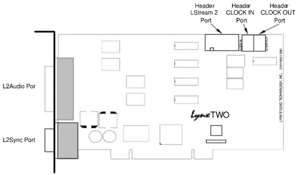
Referring to figure above, locate the L2Audio Port and the L2Sync Port on the mounting bracket of the LynxTWO. Insert the L2Audio cable into the L2Audio Port and tighten the thumb screws on the cable shell. Insert the L2Sync cable into the L2Sync Port and tighten the thumb screws on the cable shell.
Use of both cables is not a requirement. If you will be using only the analog audio capabilities of the LynxTWO, for example, there is no reason to connect the L2Sync cable.
Analog Audio
For the LynxTWO A Model, the XLR connectors on the Audio Cable, labeled IN 1, IN 2, IN 3, IN 4, OUT 1, OUT 2, OUT 3 and OUT 4 are used to connect balanced and unbalanced analog equipment to the analog inputs and outputs of the LynxTWO. The LynxTWO B Model replaces IN 3 and IN 4 with OUT 5 and OUT 6. The LynxTWO C Model replaces OUT 3 and OUT 4 with IN 5 and IN 6. Make connections to professional consoles and other balanced equipment directly with these connectors. Connect to balanced equipment with 14 TRS jacks using XLR-to-TRS adapters such as the Lynx CBL-XF2TM18 (female XLR) and the Lynx CBL-XM2TM18 (male XLR). Connect to unbalanced consumer devices with RCA jacks using XLR-to-RCA adapters such as the Lynx CBL-XF2RM18 (female XLR) and the Lynx CBL-XM2RM18 (male XLR). Adapters with line transformers are not required. Refer to the “XLR Connector Wiring and Adapters” section for information regarding XLR adapter construction.
The nominal analog signal levels are compatible with either professional or consumer equipment. Use the Trim controls on the LynxTWO Mixer application to select +4dBu for balanced professional devices or -10dBV for balanced or unbalanced consumer devices.
Please note that with 16 dB of headroom, the LynxTWO's analog outputs are capable of delivering +20 dBu signal levels. It is important to verify that the equipment you are driving is capable of handling these signal levels in order to prevent clipping or possible damage.
Digital Audio
The XLR connectors on the L2Sync Cable, labeled DIGITAL IN and DIGITAL OUT are used for AES/EBU and S/P DIF digital audio connections. Connect AES/EBU devices directly and select AES/EBU Digital Format in the LynxTWO mixer application. Connect to S/P DIF devices using the supplied XLR-to-RCA adapters. Select S/P DIF Digital Format in the LynxTWO mixer application.
LTC Connections
Two BNC connectors on the L2Sync Cable, labeled LTC IN and LTC OUT are used to connect to the LynxTWO's LTC reader and generator.
Sync Input and Clock Output Connectors
Two BNC connectors on the L2Sync Cable, labeled SYNC IN and CLOCK OUT are used to synchronize the LynxTWO with external equipment. The connectors support TTL or Composite Video level signals and should be connected with 75-ohm coaxial cable. Connect the SYNC IN connector to the clock output or video output of an external device and select External as the Sample Clock Source in the LynxTWO mixer. Adjust the clock Reference to match the incoming clock type.
CLOCK OUT is a word clock that tracks the sample rate of the LynxTWO. Connect this output to the word clock input of an external device.
Header Connectors
The Header connectors labeled CLOCK IN and CLOCK OUT are used to synchronize the LynxTWO with equipment located inside your computer. For systems containing multiple LynxTWO's, these connectors are utilized to synchronize the sample clocks of each card. The connectors support TTL level signals and should be connected using the Lynx Internal Clock Cable, Lynx Universal Clock Cable or similar 75-ohm coaxial cable.
Connect the CLOCK IN connector to the clock output of an internal device and select Header as the clock source in the LynxTWO mixer. Adjust the clock Reference to match the incoming clock type.
The signal on the CLOCK OUT header is a word clock that tracks the sample rate of the LynxTWO. Connect this output to the word clock input of an internal device or another LynxTWO.
Using Your LynxTWO
With the LynxTWO and its drivers properly installed in your computer, you can begin to use its capabilities with any third party audio application running under Windows or ASIO compliant applications under Macintosh OS. In order for these applications to access the LynxTWO you must select one of the LynxTWO audio devices in an application's configuration menu for audio or wave. Refer to the “Working with Third Party Applications” section for more information regarding device selection.
Prior to audio recording or playback, you should also use the LynxTWO Mixer application to adjust the Trim and Digital Format to match the equipment connected to your LynxTWO. Failure to do so may result in improper operation or damage to external equipment.
The LynxTWO Mixer
The LynxTWO Mixer, which is installed during setup, provides software control of the features of the LynxTWO and a visual indication of audio signal level during recording and playback.
It can be used dynamically to change operational settings of the LynxTWO, but in most cases once the settings are configured for a particular studio installation they require no adjustment.
Starting the Mixer
After installation, the LynxTWO Mixer icon will appear on the Windows task bar in the lower right corner of your screen. By double clicking on this icon with your left mouse button, the LynxTWO Mixer will launch. Alternatively, a single click with your right mouse button on this icon will open a menu that provides access to basic mixer controls and an “Open Mixer” selection that will also start the mixer.
If the icon does not appear on the Windows task bar, the LynxTWO mixer can be started by selecting Start > Programs > Lynx Studio Technology > Mixer.
General Operation
If you are simply recording and playing digital audio without synchronizing to an external clock source, you can begin using the LynxTWO by simply setting the analog Trim level and/or the Digital Format if required. Input monitoring can be enabled by selecting the desired Monitor Source and then clicking the Monitor buttons on the Analog and/or Digital Out panels.
Typically, it is convenient to keep the Mixer running on your Windows desktop to monitor signal levels or to allow instant access to Mixer controls requiring dynamic changes. The Mixer can be forced to appear on top of other applications by selecting the “Always On Top” option in the Settings pull-down menu.
For further information about the LynxTWO Mixer controls refer to the “LynxTWO Mixer Reference” section for a complete description.
Mixer Configuration Recall
The state of the Mixer settings are saved each time Windows is shut down. The stored settings are automatically recalled the next time Windows is restarted.
Clock Source Requirements
A valid clock source signal must be connected to the appropriate LynxTWO clock connector when the Sample Clock Source is set to either Digital, External, or Header. If a signal is not present, the sample clock generator will run very slowly or erratically. Symptoms of this problem include audio files that sound either fast, slow or garbled.
When a valid clock source is present, the frequency and type of clock signal must match the Sample Clock Reference setting selected in the Mixer. The frequency of word clock sources, chosen by setting the Sample Clock Source/Reference to either Digital/Auto, External/Word, or Header/Word, must match the sample rate specified when recording new files or the sample rate associated with a previously recorded file during playback. For example, if a 44.1 kHz word clock is connected to the external clock input, the Sample Clock Source/Reference must be set to External/Word and the sample rate must be set to 44.1 kHz when a new file is being recorded in an application. Failure to do so will result in files being recorded at the wrong sample rate.
Volume Faders and Signal Quality
The faders in the LynxTWO Mixer perform digital attenuation on audio signals in the digital domain. The attenuation is applied to the digitized signals just prior to the D/A converters.
As with any digital signal processing function, the digital attenuation calculations used by the LynxTWO can introduce arithmetic errors that can add small amounts of noise to signals. To insure the highest signal quality it is highly recommended that the faders be left in their maximum position during critical recording and playback. In this position, no attenuation calculations are performed.
Mono Recording and Playback Operation
When recording a file in mono, the LynxTWO will provide an audio signal from the left channel only. The audio signal from right channel is not used. When playing back a file in mono, the LynxTWO will send the signal to both the left and right outputs. To force playback on a single output, turn up the volume for the desired output, and turn down the volume for the output to be muted.
Windows Quick Audio Test
The installation of your LynxTWO can be tested using the LynxTWO Mixer and the Sound Recorder application that ships with Windows 95/98/ME and Windows NT/2000. Any other audio application capable of audio recording and playback can be used in a similar manner.
-
Connect a stereo analog signal source to the IN 1 and IN 2 connectors on the Audio cable.
-
Connect the OUT 1 and OUT 2 connectors to an amplifier or mixer capable of delivering an audio signal for listening via headphones or speakers.
-
Open the LynxTWO Mixer by double clicking on the mixer icon.
-
In the LynxTWO Mixer, set the Trim to either +4 dBu or -10 dBV to match the signal level of the connected equipment.
-
In the LynxTWO Mixer Record Panel, route the Record 1 Left & Right signal from the Analog In 1 & 2 to the Analog Out 1 & 2. This is done by pressing the “1” button for Record 1 Left and pressing the “2” button for Record 1 Right. Unmute the Monitor Mute buttons for both the left and right channels. You should hear the signal from the audio source which is connected to the analog inputs. If this is not the case, check your connections.
-
Disable input monitoring by again clicking on the Mute buttons on the Record 1 device. After doing so, the buttons should look like they are in the “out” or non-depressed position.
-
Start Sound Recorder by clicking Start > Programs > Accessories > Multimedia > Sound Recorder. Position Sound Recorder on your screen so it be easily viewed along with the LynxTWO Mixer.
-
In Sound Recorder, select the LynxTWO's audio devices by opening the Edit menu and selecting Audio Properties. Select LynxTWO Play 1 as the Preferred device for playback and LynxTWO Record 1 as the Preferred device for recording.
-
Record a short sample by clicking the red record button followed by the stop button in Sound Recorder. During recording, you should observe a graphic display of the waveform being recorded in the center display in Sound Recorder. You should also see activity on the Record 1 peak meters of the LynxTWO Mixer.
-
Playback the test sample by clicking the play button in Sound Recorder. During playback, you should observe a graphic display of the waveform being played in Sound Recorder. You should also hear the recorded audio and see activity on the Analog Out peak meters of the LynxTWO Mixer.
If the test did not operate as described or you received any errors, please refer to the “Troubleshooting” section of this manual.
Mixer Reference
The LynxTWO Mixer provides complete software control of the audio features of the LynxTWO and an indication of signal level during recording and playback. This section describes the function of each menu and control of the mixer.
Mixer Menu
With one LynxTWO installed in your computer the first selection in the Mixer Menu will be “LynxTWO Mixer” proceeded by a check mark. With more than one LynxTWO installed in your computer, the Mixer Menu will list each LynxTWO with a numeric suffix, and allow you to select which card is being controlled by the Mixer application. A check mark will appear next to the currently selected LynxTWO. Refer to the section on “Configuring Multiple LynxTWO’s” for a more information regarding the use of multiple cards.
Adapter Window
Sample Clock – This section of the LynxTWO mixer provides control of the sample clock source and reference. Since the sample clock is the master timing source, all LynxTWO audio devices on a single card must have identical sample rates. Sample clock settings cannot be changed if any LynxTWO audio device is playing or recording.
Source - Allows selection of the sample clock source from one of the following:
Internal - Clock derived from the on-board crystal oscillator.
Digital – Clock signal from the DIGITAL IN connector on the L2Sync cable. The Digital Format control must be correctly selected when selecting this clock source.
External - Clock signal from the SYNC IN connector on the L2Sync cable.
Header - Clock signal from the board-mounted CLOCK IN header.
Video – NTSC or PAL composite video signal from the SYNC IN connector on the L2Sync cable.
LStream 1 – Clock signal from the LStream port on the L2Sync connector.
LStream 2 – Clock signal from the LStream port on the board mounted header.
Reference – Provides selection of the clock source reference type from one of the following:
Auto - Automatic selection. Valid for Internal and Digital clock sources.
13.5MHz - 13.5MHz video dot clock. Valid for External and Header clock sources.
27MHz - 27MHz video dot clock. Valid for External and Header clock sources.
Word - Word clock. Valid for External and Header clock sources.
Word256 - 256 times word clock. Valid for External and Header clock sources.
Rate – Displays the current sample clock rate of the LynxTWO. When the Sample Clock Source/Reference are set to Digital/Auto, External/Word, External/Word256, Header/Word, or Header/Word256 the displayed sample rate must match the rate of the incoming clock being used for synchronization. This will ensure the correct sample rate is stored in the file’s WAV header, and that audio will playback at the correct sample rate.
Digital Format – Allows selection of either AES/EBU or S/P DIF formats for Digital In and Digital Out.
Digital Mode - Selects the mode for the Sample Rate Converter on the Digital Input.
SRC On - Default. The sample rate converter is on.
SRC Off: Clock Synchronous – Turns off the sample rate converter and indicates that the digital input and digital output clocks are synchronous. This mode is useful when the digital output is feeding the digital input either directly or through an external device with no sample rate converter.
SRC Off – The sample rate converter is off. When in this mode the Sample Clock Source must be set to Digital. Use this mode when recording non-audio formats such as Dolby Digital, DTS or others formats that require bit-perfect transfers.
SRC On: Digital Out – The sample rate converter is turned on, but it is used by the Digital Output instead of the Digital Input. The Digital Input sample rate will determine the actual rate of the Digital Output. This mode is useful when sending audio to external equipment at a different rate than it was recorded.
Transmit Only – Disables the Digital Input and the sample rate converter. Used for testing purposes only.
Digital Input Status – Displays real-time status of the digital input, updated 4 times a second.
Digital In Rate - Displays the measured rate of the incoming digital signal.
SRC Ratio - Indicates the sample rate conversion ratio in SRC On mode.
Digital In Mode – Displays real-time status of the digital input. Professional status is generally associated with an AES/EBU signal, and consumer status is generally associated with an S/P DIF signal.
Analog Trim - Sets the nominal analog input and output levels for the LynxTWO to either +4dBu or -10dBV . Four controls are provided, each for a pair of inputs and outputs.
Frequency Counters - Displays the real-time clock frequency for the following sources:
L/R Clock - Left/Right Clock, which is the currently selected sample rate.
Digital Input - This is the same clock as the Digital In Rate above.
External - Clock signal from the SYNC IN connector on the L2Sync cable.
Header - Clock signal from the CLOCK IN header connector.
Video - Composite video signal from the SYNC IN connector on the L2Sync cable. 15.734kHz for NTSC or 15.625kHz for PAL.
LStream 1 – Clock signal from the LStream port on the L2Sync connector.
LStream 2 – Clock signal from the LStream port on the board mounted header.
PCI Bus – The speed of the PCI Bus of the host computer.
LTC Input – This section of the LynxTWO Mixer provides control of the Longitudinal Timecode Receiver.
Lock - When lit, indicates the LTC Receiver is locked to an incoming signal.
Direction - Indicates the direction of the timecode from the LTC Receiver.
Drop Frame - Indicates if drop frame is specified for the incoming signal.
Frame Rate - Indicates the actual frame rate of the LTC Receiver.
Position - Indicates the last frame position decoded from the LTC Receiver.
LTC Output - This section of the LynxTWO Mixer provides control of the Longitudinal Timecode generator.
Enable - When checked, the LTC generator is enabled.
Frame Rate – Provides selection of the frame rate of the LTC generator. Allowed rates are 24, 25, 29.97 and 30 fps.
Drop Frame - Used to indicate drop frame for 29.97 and 30 fps frame rates.
Sync Source – Selects the synchronization source the the LTC generator.
Position - Used to enter the starting position for the LTC generator and display the current timecode position when the generator is enabled.
Recalibrate Converters – Used to calibrate DC offset of the A/D and D/A converters. When the LynxTWO driver first loads, the converters are calibrated for optimum fidelity. Over time temperature changes inside your computer may cause the DC offset to drift slightly. Because of this, Lynx recommends recalibration 15 to 30 minutes after your computer has been turned on and whenever significant changes in room temperature occur.
Dither Type – Provides selection of the type of dither used on all record channels. The selection may be one of the following:
None - Dither is disabled. Volume processing utilizes rounding prior to truncation.
Triangular - Enables the addition of triangular probability density dither. This type of dither is free of data-dependent noise modulation effects, but decreases signal-to-noise ratio by 4.8 dB. Triangular is the preferred dither type in most cases.
Shaped Triangular - Enables the addition of shaped triangular probability density dither. This type of dither is essentially a high-pass filtered triangular dither that places most of the dither energy at higher frequencies making it less audible to the human ear. Shaped triangular dither also decreases signal-to-noise ratio by 4.8 dB.
Rectangular - Enables the addition of rectangular probability density dither. This type of dither decreases the signal-to-noise ratio by 3 dB (less than triangular), but is less desirable because of its noise modulation effects.
Record Window
Record Source Selection – Provides selection for the source of each associated record channel. Each channel may take its source from any one of the 24 available inputs.
Peak Meters - Displays the instantaneous level of the audio being sent to the LynxTWO.
Mute - Provides a mute function for each associated input.
Dither - Enables / Disables dither for each associated input. The Dither type is specified in the Adapter window.
Monitor Section
Output Selection – Provides buttons for routing input channels to output channels for monitoring. Each button represents a physical output on the LynxTWO.
Volume Faders - Controls digital attenuation of the audio being monitored. No volume adjustment for the signal being recorded is available.
Mute - Provides a mute function for each associated monitor channel.
Phase - Inverts the phase for each associated monitor channel.
Device Format - Displays the bit-depth and number channels in use on this device. This is set by the audio application using each record device and is provided for reference purposes only.
Activity Indicators – The names at the bottom of the Record and Play windows reflect the name of its associated wave device. When a device is inactive its name is shown as blue text. When a device is active (currently open for play or record) its name appears in red text.
Play Window
Output Selection – Provides buttons for routing play device channels to output channels. Each button represents a physical output on the LynxTWO.
Volume Faders - Controls digital attenuation of the audio being played.
Mute - Provides a mute function for each associated play device channel.
Phase - Inverts the phase for each associated play device channel.
Device Format - Displays the bit-depth and number channels in use on this device. This is set by the audio application using each play device and is provided for reference purposes only.
Activity Indicators – The names at the bottom of the Record and Play windows reflect the name of its associated wave device. When a device is inactive its name is shown as blue text.
Outputs Window
Overload Indicator – Provides instantaneous overload indication of the audio being played or monitored. Once an overload condition has occurred the overload indicator remains until reset manually by the user by clicking on the control.
Peak Meters - Displays the instantaneous level of the audio being played or monitored.
Volume Faders – Controls digital attenuation of the audio being played or monitored. This control acts on the digital signals before D/A conversion. With the volume fader at its maximum position, the vertical line within the fader turns black, no volume calculation is performed and the audio stream is unaltered. This is the recommended position for critical recording and mixdown sessions in which the highest signal quality is required. Volume control processing is done prior to peak meter readings causing the peak meters to reflect any volume control changes. Since volume changes act on the digitally converted signals, they have no effect on the analog full-scale input and output levels. This must be done with the Trim control. When the volume fader is not at its maximum or minimum position, the vertical line within the fader turns red to indicate that the volume control is active.
Mute - Provides a mute function for each associated output.
Phase - Inverts the phase for each associated output. This is a master control and overrides the phase controls for any record monitor or play channel assigned to this output.
Dither - When pressed, enables the addition of triangular probability density dither for each associated output.
Working with Third Party Applications
Compatibility
The drivers included with your LynxTWO provide compatibility with all standard third party audio editing applications that communicate with Windows Wave audio, DirectSound and ASIO devices. A list of applications that have been tested for compatibility is provided on the Lynx web site at http://www.lynxstudio.com/swlist.html.
LynxTWO Devices
Third party applications communicate with the LynxTWO through its installed driver. The driver presents the LynxTWO's audio capabilities to applications as standard multimedia, DirectSound or ASIO devices.
Most, if not all, third party applications provide device selection in configuration, options, or preference setting windows or menus. For two channel or stereo audio applications, a separate selection option is typically provided for the input or recording device and the output or playback device. Multitrack applications provide multiple input and output device selection menus or windows. Refer to the documentation included with your application to determine how to select audio devices.
With the LynxTWO properly installed in your computer, the digital audio devices will be available to applications, and their names will appear in their device selection menus as follows:
| LynxTWO Record 1 LynxTWO Play 1 |
| LynxTWO Record 2 LynxTWO Play 2 |
| LynxTWO Record 3 LynxTWO Play 3 |
| LynxTWO Record 4 LynxTWO Play 4 |
| LynxTWO Record 5 LynxTWO Play 5 |
| LynxTWO Record 6 LynxTWO Play 6 |
| LynxTWO Record 7 LynxTWO Play 7 |
| LynxTWO Record 8 LynxTWO Play 8 |
When more than one LynxTWO is installed in your system, the device names will contain a numeric adapter ID assigned by the operating system. For example, the analog output device on adapter 2 would be listed as “LynxTWO 2 Record 1”. Refer to the “Configuring Multiple LynxTWO’s” section for more information regarding this topic.
Controlling Audio Bit Depth
Creating a audio file with a particular bit depth (or resolution) is controlled through an application's recording settings. These settings are typically adjusted in an audio device configuration menu or in a recording setup window just prior to recording. When recording is initiated the LynxTWO will generate audio samples of the desired resolution.
Bit depth control during playback of an audio file is also an application issue. When a file is played, the recorded bit depth is read from the file's header by the application. The application uses this information to set the resolution of the LynxTWO.
The LynxTWO supports file types with 8, 16, 24, or 32 bit word widths. Note that 32-bit files contain 24-bit data with zero data in the least significant bit positions.
The LynxTWO Mixer application displays the currently selected bit depth for each device just above the device name in the Record window and the Play window.
Simultaneous Device and Multitrack Operation
The sixteen audio devices of the LynxTWO operate completely independent in terms of whether they are in recording or playback modes and their associated audio files. This implies that the devices can operate simultaneously and support the so-called “full-duplex” mode where, for instance, the LynxTWO Record 1 device is recording while the LynxTWO Play 1 device is playing.
Although the devices act independently, when multiple devices are being used to record or play multiple audio files simultaneously, the LynxTWO driver has the capability to synchronously start all devices with sample accuracy. This is especially important for maintaining synchronization during playback of multiple devices and overdubbing.
By using all of the record and play devices, sixteen track recording and playback is possible. Again, control of this multi-channel operation is simply a matter of device selection in any compatible multitrack audio application.
Configuring Multiple LynxTWO's
More than one LynxTWO card can be installed in a computer for additional audio channels. If required, all LynxTWO's in a computer can be configured to maintain sample accurate synchronization during digital audio recording and playback.
Cards are synchronized in a master-slave arrangement. One card is selected as the master which provides the word clock source for the other slave cards in the system. From the master, the word clock signal is daisy-chained from one slave to the next.
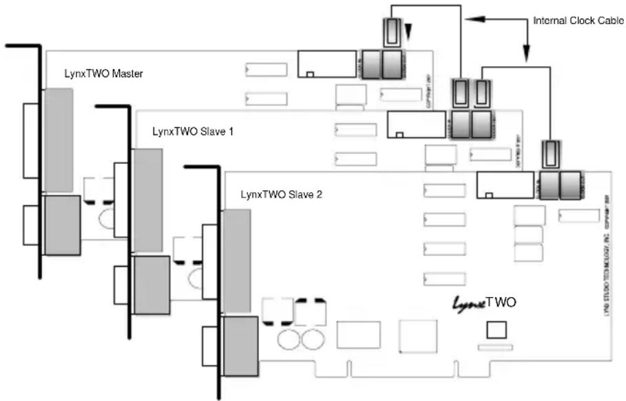
Word clock signals can be connected internally using the Internal Clock Cable, which is available from Lynx. The CLOCK OUT header of one card is connected to the CLOCK IN header of the next card. A separate cable is required for each slave card in the system.
Alternatively, the SYNC IN and CLOCK OUT connectors on the L2Sync cable can be connected externally with a standard 75 ohm BNC cable.
Adapter ID's in a Multiple Card System
When multiple LynxTWO cards are installed in a computer they are automatically assigned unique adapter ID numbers. These adapter ID's provide a means to identify and communicate with each LynxTWO when using the LynxTWO Mixer application and to select audio devices in third party applications.
In the LynxTWO Mixer, the adapter that a user wishes to control is selected from the Mixer pull-down menu. In a system with four LynxTWO's the adapters will be listed as follows:
LynxTWO 1 Mixer LynxTWO 2 Mixer LynxTWO 3 Mixer LynxTWO 4 Mixer
In each case, the adapter ID is the numeric character in each selection.
Most third party applications provide a setup or configuration menu for selecting a desired wave audio device for recording and playback. With multiple LynxTWO's in a system, each device name will contain the adapter ID. For example, the first play device on adapter 2 would be listed as “LynxTWO 2 Play 1”.
Selection of Master and Slave Clocks
In order to select master and slave LynxTWO's in a system, each adapter ID must be first physically associated with a LynxTWO installed in a computer slot. Since ID assignment is automatic, determining this association is somewhat trial and error. The procedure is as follows:
- Connect at least one analog output channel of each LynxTWO to an amplifier, mixing console or other equipment that will provide audio monitoring.
- Choose an audio application that allows selection of wave audio devices for audio playback.
-
Select "LynxTWO 1 Play 1" as the playback device.
-
Listen to the playback of any wave file and note which LynxTWO card is generating the audio signal. In this case, the card generating audio is adapter 1.
- Repeat steps 3 and 4, for “LynxTWO 2 Play 1”, “LynxTWO 3 Play 1”, and so on until all LynxTWO’s in your system have been identified.
The next step is to choose which LynxTWO will act as a master. This choice is based on preference only, but for ease of connection it makes sense to choose a LynxTWO that is on one end of the PCI slot array on your motherboard.
Cable Connections
Starting with the master LynxTWO, insert the plug on one end of a Lynx Internal Clock Cable into the CLOCK OUT header, until it clicks and locks into place. This header is polarized to ensure the correct orientation of the cable plug. Insert the plug on the free end of the cable into the CLOCK IN header, on the nearest slave LynxTWO. Connect each slave in a similar manner. Refer to the figure below.
flowchart
graph TD
    subgraph LynxTWO Master
        A[" "] --> B["LynxTWO Slave 1"]
        B --> C["LynxTWO Slave 2"]
        C --> D["LynxTWO"]
    end

    subgraph LynxTWO Slave 1
        E[" "] --> F["LynxTWO Slave 2"]
        F --> G["LynxTWO"]
    end

    subgraph LynxTWO Slave 2
        H[" "] --> I["LynxTWO"]
    end

    subgraph Internal Clock Cable
        J[" "] --> K["LynxTWO"]
    end

    style LynxTWO Master fill:#f9f,stroke:#333
    style LynxTWO Slave 1 fill:#ccf,stroke:#333
    style LynxTWO Slave 2 fill:#cfc,stroke:#333
    style Internal Clock Cable fill:#fcc,stroke:#333
    style LynxTWO Master fill:#fff,stroke:#333
    style LynxTWO Slave 1 fill:#fff,stroke:#333
    style LynxTWO Slave 2 fill:#fff,stroke:#333
    style Internal Clock Cable fill:#fff,stroke:#333
Alternatively, if clock connections are made externally using the SYNC IN and CLOCK OUT connectors on the L2Sync cable, use BNC cables to make connections between cards in the same sequence as described above.
Mixer Settings
With the clock connections in place, the sample clock settings of each LynxTWO must be adjusted using the LynxTWO Mixer.
For the master LynxTWO:
- Select the master LynxTWO from the Mixer pull-down menu.
- Select a desired Sample Clock Source.
- Select a desired Sample Clock Reference.
For each slave LynxTWO:
- Select the slave LynxTWO from the Mixer pull-down menu.
- Set the Sample Clock Source to Header if internal clock connections are used or External if external clock connections are used.
- Set the Sample Clock Reference to Word.
Troubleshooting
When Windows starts I see a LynxTWO Mixer error - "No mixer device drivers are available".
This error will appear when the LynxTWO Mixer is loading during Windows startup and the LynxTWO is not installed correctly. You should check the following items:
- With the computer power off, verify that the card is properly seated in the PCI slot.
- Verify the LynxTWO's resources are not conflicting with some other device in your system. For Windows 95/98, check in the Device Manager (Start > Control Panel > System > Device Manager > Sound, video and game controllers > LynxTWO > Resources) to verify there are no resource conflicts. For Windows NT check in Windows NT Diagnostics (Start > Programs Administrative Tools > Windows NT Diagnostics > Resources) to verify there are no resource conflicts. If there is a resource conflict, you may need to move the LynxTWO to a different slot in your computer as some motherboards have specific resources assigned to specific slots, or change the interrupt setting in the BIOS setup screen. Please refer to your motherboard/computer documentation to determine how to change the interrupt for a PCI device.
I installed the LynxTWO in the PCI slot before I ran Setup.exe for Windows 95/98, what do I do now?
The device manager in Windows 95/98 requires the .INF file for a device to be installed before the Plug and Play scan to detect new hardware (which happens on each boot). This is why Setup.exe should generally be run before you install the LynxTWO into your computer. To correct this follow the steps listed here:
- Load the device manager by clicking on Start > Control Panel > System > Device Manager.
- There should be an entry called “+ ? Other Devices” listed about 3/4 down the page. Click on the + sign. “PCI Multimedia Audio Device” should appear.
- Click on "PCI Multimedia Audio Device", then click on "Remove".
- A "Confirm Device Removal" dialog box should appear, click on "OK". It might take a couple of seconds for this dialog box to close.
- Click on "Refresh". After several seconds, a "New Hardware Found" dialog box will appear. Depending on your installation of Windows 95/98, another dialog box may appear asking for setup disk. The location you need to specify is: C:\Windows\System Click on "OK" after entering this path.
- You may need to reboot your machine once this completes to get everything running properly.
Audio playback sounds really slow or erratic.
The Sample Clock Source selected in the LynxTWO Mixer is not connected to an active clock source. In this case, the sample clock generator on the LynxTWO runs very slow or erratic. This will occur if Digital is selected as the Sample Clock Source and there is either no connection to the LynxTWO's digital input or the device connected is turned off. The same situation will occur if either External or Header is selected as the clock source and there is no connection to the corresponding inputs on the card.
Audio playback sounds fast or slow when I am using the digital input as the clock source.
When the digital input is selected as the clock source, the LynxTWO's sample clock will run at the sample rate of the incoming digital input signal. In the case when the sample rate of this signal is 48 kHz and a file being played was actually recorded at 44.1 kHz, the audio will playback fast. To solve this problem either change the sample rate of the device driving the digital input or select Internal as the sample clock source using the LynxTWO mixer.
How do I minimize record monitor latency when I am doing overdubs?
Use the LynxTWO's on-board monitor circuitry. This is controlled by the LynxTWO mixer.
What does the green LED on the LynxTWO indicate?
When lit, the LED indicates successful initialization of the LynxTWO and the driver.
When I connect the LynxTWO analog outputs to the MIC inputs on my Mackie mixer I hear distortion.
The MIC inputs are being overdriven. Even with the mic gain adjusted to its lowest setting, the maximum signal level that the MIC inputs of the smaller Mackie mixers can handle is +14 dBu. In the +4 dBu trim setting, the LynxTWO is capable of delivering a +20 dBu signal. To solve this problem use 1/4" line inputs of the mixer. This requires the use of XLR to TRS adapters as described in the "External Connections" section.
I connect my microphone directly to the LynxTWO Analog Input connectors, but the level is very low, what is going on?
The LynxTWO Analog Input connectors should be connected line level devices only. To record from a microphone, first route the signal through a microphone pre-amplifier or mixer and then into the LynxTWO.
Where on the LynxTWO do I connect my internal CD-ROM drive?
The LynxTWO has no connector for an internal CD-ROM drive. We recommend using digital audio extraction software to capture the audio data from your CD's and saving it to your hard disk drive as .WAV files. Using this method, the audio files can be played back using the D/A converters on the LynxTWO which have far superior performance to those found in most CD-ROM drives. If your CD-ROM/DVD drive can reliably extract digital audio then you could use Windows Media Player (Version 7 or higher) to extract digital audio from CDs and play it in real-time with no physical connection between the LynxTWO and the CD-ROM drive.
Can I leave my current sound card in my computer while using the LynxTWO?
You may leave your existing sound card in your computer as long as you have a free PCI slot and interrupt for the LynxTWO. You may need to reconfigure certain software to access the LynxTWO instead of your existing sound card. Please refer to the “Working with Third Party Applications” section for details.
Can the LynxTWO share interrupts with other devices?
The LynxTWO is able to share interrupts with other PCI devices, as long as the other PCI device's driver is written correctly to share interrupts. The LynxTWO is not able to share interrupts with ISA devices (such as a modem, serial port, printer port, keyboard or mouse). The BIOS on many motherboards require the user to manually reserve an interrupt (IRQ) for an ISA device. If this is not done the BIOS may assign an ISA device and a PCI device the same interrupt which results in a conflict.
Does the LynxTWO support Dolby® AC-3 (Dolby Digital) and DTS?
The LynxTWO supports Dolby AC-3 and DTS through its Digital In and Digital Out ports. This allows an application to record an incoming Dolby or DTS encoded audio stream, as well as play an encoded stream through an external decoder. This ability is available for both S/P DIF and AES/EBU modes. The LynxTWO is able to recognize and generate the "Non-Audio" bit while recording for both S/P DIF and AES/EBU.
Is it safe to connect the LynxTWO analog outputs to a mixer whose inputs provide "phantom" power?
The LynxTWO should never have phantom power applied to it's output. This can easily be avoided by connecting the LynxTWO to the line inputs in your mixer, and not the microphone inputs. Generally, lower cost mixers have line inputs on TRS connectors. If you use XLR to TRS adapters cables you should be able to connect the LynxTWO to your mixer and avoid any phantom powering problems.
Support
We are devoted to making your experience with LynxTWO trouble-free and productive. If you have questions or comments regarding the operation of your LynxTWO please check the “Troubleshooting” section of this manual and the FAQ and Troubleshooting topics on the Support section of the Lynx web site at:
http://www.lynxstudio.com/support.html
If you are unable to find information about your problem please email us at:
support@lynxstudio.com
In your email message include the following information:
• The serial number of your LynxTWO.
- Which operating system you are using.
• The type of computer you are using.
- The name of the application you are using.
- A detailed description of the problem including any error messages you received.
We will provide a response in a timely manner.
Telephone support is available by calling (949) 515-8265 from 9AM to 5PM Pacific Time, Monday through Friday, excluding Holidays. Please be sure to have the above information available before calling.
Appendix
Specifications
Analog I/O
| A Model Four inputs / four outputs | |
| B Model Two inputs / six outputs | |
| C Model Six inputs / two outputs | |
| Type Electronically balanced or unbalanced, XLR connectors on L2Audio Cable | |
| Level +4 dBu nominal/+20dBu max. or -10dBV nominal/+6dBV max., software selectable in channel pairs | |
| Input Impedance | Balanced mode: 24 kΩ , Unbalanced mode: 12 kΩ |
| Output Impedance | Balanced mode: 100 Ω , Unbalanced mode: 50 Ω |
| Output Drive Capability | 600 Ω impedance, 0.16 μF capacitance |
| A/D and D/A Type 24-bit, multi-level, delta-sigma | |
| Sample Rates 8 kHz to 200 kHz, including all standard rates with variable adjustment | |
| Bit Depth 8, 16, 24 or 32 bit file types | |
| On-board Buffer Size 16 Kbytes per input and output stream (mono or stereo) | |
Analog In Performance (measured in 24-bit mode with card installed in computer)
| Frequency Response 20 - 20 kHz, ± 0.05 dB at 44.1 kHz sample rate | |
| Dynamic Range 117 dB, A-wtd. | |
| Signal-to-Noise | 116 dB, A-wtd. |
| Channel Crosstalk | <-120 dB, 1 kHz signal @ -1dBFS |
| THD+N | -104 dB (0.0006%) @ -8 dBFS, 1kHz signal 22Hz-22kHz BW |
Analog Out Performance (measured in 24-bit mode with card installed in computer)
| Frequency Response 20 - 20 kHz, ± 0.05 dB at 44.1 kHz sample rate | |
| Dynamic Range 117 dB, A-wtd. | |
| Signal-to-Noise | 117 dB, A-wtd. |
| Channel Crosstalk | <-120 dB, 1 kHz signal @ -1dBFS |
| THD+N | -104 dB (0.0006%) @ -8 dBFS, 1kHz signal 22Hz-22kHz BW |
Digital I/O
| Number / Type | One input and one outputAES/EBU or S/P DIF format, transformer coupled, XLR connectors on L2Sync Cable |
| Sample Rates 32 kHz, 44.1 kHz, 48 kHz, 88.2 kHz, 96 kHz | |
| Sample Rate Conversion | Supports conversion ratios up to 3:1 on digital input, 128 dB dynamic range |
| Bit Depth 8, 16, 24 or 32 bit file types | |
| Control / Status | Complete subcode and channel status support |
| On-board Buffer Size 16 Kbytes per input and output stream (mono or stereo) | |
LStream Expansion Ports
| Number | One external and one internal |
| Compatibility | Supports Lynx ADAT, AES, TDIF, and other multichannel expansion modules |
| Type High-speed serial, eight channel input and output (each port), 24-bit data, 96kHz rate | |
SMPTE Time Code I/O
| Type LTC receiver (in) and generator (out), BNC connectors on L2Sync Cable |
| Frame Rates 24, 25, 29.97, 30 Hz - drop and non-drop |
| Input Sync Rate 1/30 to 80 times nominal frame rate |
| Input Levels 200 mV to 10V / 10KΩ |
| Output Level 1V / 75Ω |
Clock I/O
| Number External: one input and output, BNC connectors on L2Sync CableInternal: one input and output on board-mounted headers |
| Level / Impedance TTL (clock signals) / 1Vpp (video) 75Ω |
| Type Input: word clock, 256X word clock, 13.5 and 27 MHz video clocks, NTSC or PAL composite video Output: word clock |
On-board Digital Mixer
| Channel Capacity 32 input channels, 16 sub outputs |
| Resolution / Dither 32-bit / TPDF, Shaped TPDF, or RPDF |
| Monitor Mixing Any input to multiple outputs |
| Metering Peak levels to -114 dB on all inputs and outputs |
Connections
| Audio Port Bracket-mounted 25-pin female D-sub connector for analog audio input and output |
| Sync Port Bracket-mounted 15-pin high-density female D-sub connector for digital input and output, sync in and out |
Cables (Included)
| L2Audio Cable | 25-pin male D-sub to male and female XLR connectors on six-foot shielded twisted pair cabling |
| L2Sync Cable | 15-pin high-density male D-sub to (1) male and (1) female XLR on six-foot shielded twisted pair cabling and (4) female BNC connectors on two-foot 75Ω coaxial cabling |
Software
| Windows Drivers | Windows 98 / ME / NT/ 2000 / XP: MME, ASIO 2.0, and DirectSound |
| Macintosh Drivers | ASIO 2.0 for OS 9 |
| LynxTWO Mixer App | Provides complete control of digital mixer and all hardware settings. |
General
| PCI Bus | Version 2.2 compliant |
| Data Transfers | Up to 132 Mbytes/sec using custom 16-channel, zero-wait state, scatter-gather DMA engine; bus mastering |
| Size | 5.0" H X 7.4" W X 0.75" D (half-size PCI card) |
| Shipping Weight | 3.25 lbs. with cables |
| Certifications | CE and FCC Class B |
XLR Connector Wiring and Adapters
This section describes the proper wiring of cables that can be used to adapt both the analog and digital audio XLR connectors on the LynxTWO Audio Cable.
Balanced Connections
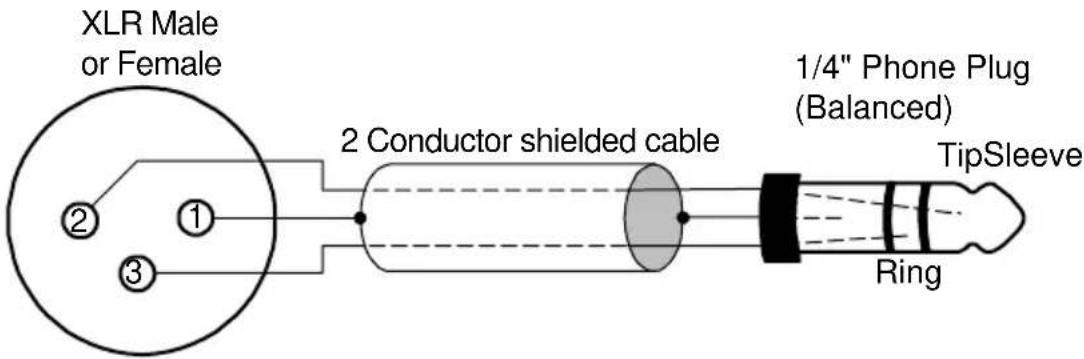
The wiring method for balanced connections with XLR connectors to balanced TRS ( 14 ” phone) connectors using shielded twisted pair cable (2 wire + shield) is as follows:
XLR Pin 1 (GND) to cable shield and to the TRS sleeve
XLR Pin 2 (+) to one signal wire and to the TRS tip
XLR Pin 3 (-) to the other signal wire and to the TRS ring
Unbalanced Connections with Twisted Pair Cable
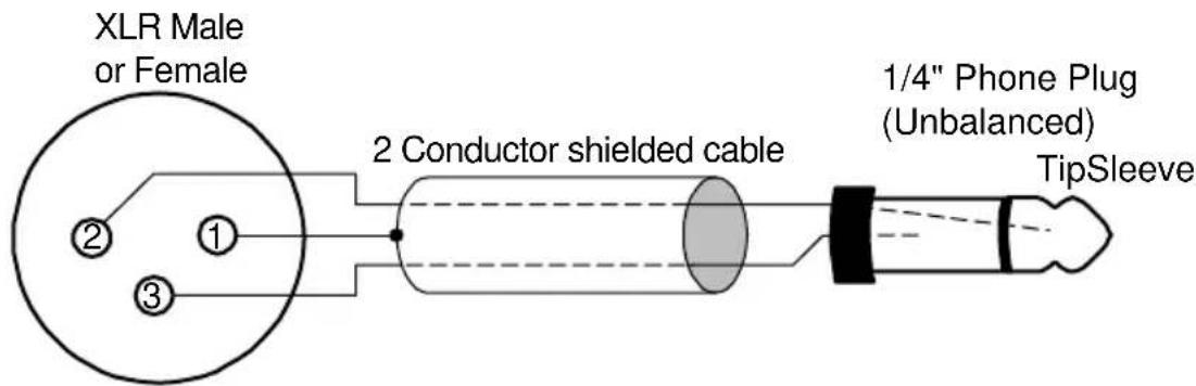
The wiring method for unbalanced connections with XLR connectors to 14 " phone connectors (tip and sleeve only) using shielded twisted pair cable (2 wire + shield) is as follows:
XLR Pin 1 (GND) to cable shield with no connection on the other end
XLR Pin 2 (+) to signal wire and to the 1/4" phone tip
XLR Pin 3 (-) to the other signal wire and to the 1/4" phone sleeve
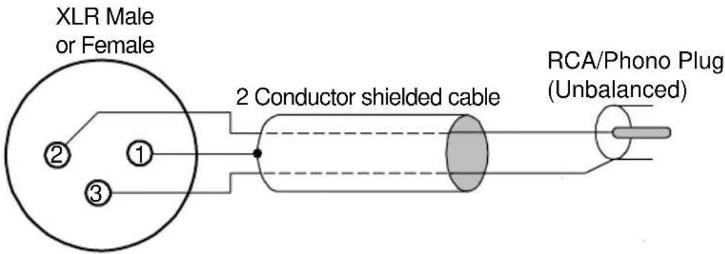
The wiring method for unbalanced connections with XLR connectors to RCA/Phono phone connectors using shielded twisted pair cable (2 wire + shield) is as follows:
XLR Pin 1 (GND) to cable shield with no connection on the other end XLR Pin 2 (+) to signal wire and to the Phono center pin XLR Pin 3 (-) to the other signal wire and to the Phono sleeve
Unbalanced Connections with Single Conductor Cable
In some cases it may be necessary to use single-conductor cable to adapt to unbalanced devices. These cables are considerably more susceptible to interference and grounding problems than the two conductor cables shown above. Two-conductor cables should be used whenever possible.
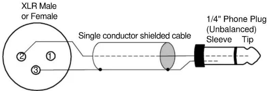
The wiring method for unbalanced connections with XLR connectors to unbalanced 14 " phone connectors (tip and sleeve only) using coaxial cable (1 wire + shield) is as follows:
XLR Pin 1 (GND) no connection XLR Pin 2 (+) to signal wire and to the 14 " phone tip XLR Pin 3 (-) to the cable shield and to the 14 " phone sleeve
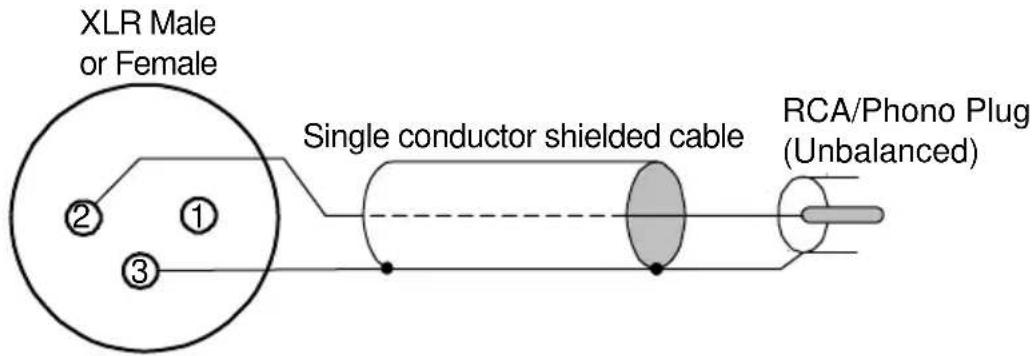
The wiring method for unbalanced connections with XLR connectors to unbalanced RCA/Phono phone connectors using coaxial cable (1 wire + shield) is as follows:
XLR Pin 1 (GND) no connection
XLR Pin 2 (+) to signal wire and to the Phono center pin
XLR Pin 3 (-) to the cable shield and to the Phono sleeve
Connector Pinouts
L2Audio Port
The L2Audio Port is a female 25-pin D-connector with the following connections:
| Pin | Signal | Pin | Signal |
| 1 | t | oH4TUO | |
| 2 | OUT 4 Gnd | 15 | IN 4 Hot |
| 3 | IN 4 Cold | 16 | IN 4 Gnd |
| 4 | t | oH3TUO | |
| 5 | OUT 3 Gnd | 18 | IN 3 Hot |
| 6 | IN 3 Cold | 19 | IN 3 Gnd |
| 7 | OUT 2 Hot | 20 | OUT 2 Cold |
| 8 | OUT 2 Gnd | 21 | IN 2 Hot |
| 9 | IN 2 Cold | 22 | IN 2 Gnd |
| 10 | OUT 1 Hot | 23 | OUT 1 Cold |
| 11 | OUT 1 Gnd | 24 | IN 1 Hot |
| 12 | IN 1 Cold | 25 | IN 1 Gnd |
| 31 | ne |
The LynxTWO B Model replaces IN 3 and IN 4 with OUT 5 and OUT 6. The LynxTWO C Model replaces OUT 3 and OUT 4 with IN 5 and IN 6.
L2Sync Port
The L2Sync Port is a female, high-density 15-pin D-connector with the following connections:
| Pin | Signal | Pin | Signal |
| 1 | 9 | Digital Out Hot | |
| 2 | 10 | Digital In Cold | |
| 3 | LTC In + | 11 | |
| 4 | Sync In + | 12 | |
| 5 | Digital In Hot | 13 | LTC Out + |
| 6 | 14 | Clock Out + | |
| 7 | LTC Gnd | 15 | Digital Out Cold |
| 8 | Clock Gnd |
Header Connectors
The LStream 2 port is a 14 pin header shrouded in black plastic labeled JP1.
The CLOCK IN port labeled JP2 and CLOCK OUT port labeled JP3 are two-pin headers shrouded in black plastic. For both connectors, Pin 1 carries the clock signal and Pin 2 is a ground signal. Pin 1 is located on the left side of each connector when viewing the component side of the board.
Instructions to the User
This equipment has been tested and found to comply with the limits for a class B digital device, pursuant to part 15 of the FCC Rules. These limits are designed to provide reasonable protection against harmful interference in a residential installation. This equipment generates, uses and can radiate radio frequency energy and if not installed and used in accordance with the instructions, may cause harmful interference to radio communications. However, there is no guarantee that interference will not occur in a particular installation. If this equipment does cause harmful interference to radio or television reception, which can be determined by turning the equipment off and on, the user is encouraged to try to correct the interference by one or more of the following measures:
- Reorient or relocate the receiving antenna.
- Increase the separation between the equipment and receiver.
- Connect the equipment into an outlet on a circuit different from that to which the receiver is connected.
- Consult the dealer or an experienced radio/TV technician for help.
In order to maintain compliance with FCC regulations, shielded cables must be used with this equipment. Operation with non-approved equipment or unshielded cables is likely to result in interference to radio and TV reception. The user is cautioned that changes and modifications made to the equipment without the approval of manufacturer could void the user's authority to operate this equipment.
EMC Certifications
FCC DECLARATION OF CONFORMITY
TRADE NAME: Computer Audio Card
MODEL NUMBER: LynxTWO
COMPLIANCE TEST REPORT NUMBER: B10305A1
COMPLIANCE TEST REPORT DATE: March 23, 2001
RESPONSIBLE PARTY (IN USA): Lynx Studio Technology, Inc.
ADDRESS: 1048 Irvine Ave # 468, Newport Beach, CA 92660
TELEPHONE: (949) 515-8265
This equipment has been tested and found to comply with the limits for a Class B digital device, pursuant to Part 15 of the FCC rules. These limits are designed to provide reasonable protection against harmful interference in a residential installation. This equipment generates, uses, and can radiate radio frequency energy and, if not installed and used in accordance with the instructions, may cause harmful interference to radio communications. However, there is no guarantee that interference will not occur in a particular installation.
If the unit does cause harmful interference to radio or television reception, please refer to your user's manual for instructions on correcting the problem.
I the undersigned, hereby declare that the equipment specified above conforms to the above requirements.
Newport Beach, California
June 15, 2001

Robert Bauman
Compliance Engineer
EC DECLARATION OF CONFORMITY
MANUFACTURERS NAME: Lynx Studio Technology, Inc.
MANUFACTURER ADDRESS: 1048 Irvine Ave # 468
Newport Beach, CA 92660, U.S.A.
EUROPEAN REPRESENTATIVE'S NAME: HHB Communications, Ltd.
EUROPEAN REPRESENTATIVE'S ADDRESS: 73-75 Scrubs Lane
London NW10 6QU, United Kingdom
COMPLIANCE TEST REPORT NUMBER: B10307W1
COMPLIANCE TEST REPORT DATE: March 9, 2001
TYPE OF EQUIPMENT: Information Technology Equipment
EQUIPMENT CLASS: Residential, Commercial and Light Industry
MODEL NUMBER: LynxTWO
CONFORMS TO THESE STANDARDS: EN50022: 1998, EN55024:1998,
EN61000-3-2:1995, EN61000-3-3:1995
YEAR OF MANUFACTURE: 2001
I the undersigned, hereby declare that the equipment specified above conforms to the above directives and standards.
Newport Beach, California
June 15, 2001

Robert Bauman
Compliance Engineer
License Agreement
This legal document is an agreement between you and Lynx Studio Technology, Inc. By opening the sealed board package, or written materials, you are agreeing to become bound by the terms of the agreement, which includes this License and Limited Warranty (collectively the “Agreement”). This Agreement constitutes the complete agreement between you and Lynx Studio Technology, Inc. If you do no agree to the terms of the Agreement, DO NOT OPEN the anti-static bag containing the LynxTWO board. Promptly return the unopened package and all other items using the original packaging to the location of purchase.
Limited Warranty
Lynx Studio Technology, Inc. (“Lynx”) warrants this product to be free of defects in material and workmanship for a period of one year from the date of original retail purchase. This warranty is enforceable only by the original retail purchaser. To be protected by this warranty, the purchaser must complete and return the enclosed warranty card within 14 days of purchase.
During the warranty period Lynx shall, at its sole and absolute option, either repair or replace free of charge any product that proves to be defective on inspection by Lynx or its authorized service representative. In all cases disputes concerning this warranty shall be resolved as prescribed by law.
To obtain warranty service, the purchaser must first call or write Lynx at the address and telephone number printed below to obtain a Return Authorization Number and instructions concerning where to return the unit for service. All inquiries must be accompanied by a description of the problem. All authorized returns must be sent to Lynx or an authorized Lynx repair facility postage prepaid insured and properly packaged. Proof of purchase must be presented in the form of a bill of sale, canceled check or some other positive proof that the product is within the warranty period. Lynx reserves the right to update any unit returned for repair. Lynx reserves the right to change or improve design of the product at any time without prior notice. This warranty does not cover claims for damage due to abuse, neglect, alteration or attempted repair by unauthorized personnel, and is limited to failures arising during normal use that are due to defects in material or workmanship in the product.
ANY IMPLIED WARRANTIES, INCLUDING IMPLIED WARRANTIES OF MERCHANTABILITY AND FITNESS FOR A PARTICULAR PURPOSE, ARE LIMITED IN DURATION TO THE LENGTH OF THIS LIMITED WARRANTY. Some states do not allow limitations on how long an implied warranty lasts, so the above limitation may not apply to you.
IN NO EVENT WILL LYNX BE LIABLE FOR INCIDENTAL, CONSEQUENTIAL OR OTHER DAMAGES RESULTING FROM THE BREACH OF ANY EXPRESS OR IMPLIED WARRANTY, INCLUDING, AMONG OTHER THINGS, DAMAGE TO PROPERTY, DAMAGE BASED ON INCONVENIENCE OR ON LOSS OF USE OF THE PRODUCT, AND, TO THE EXTENT PERMITTED BY LAW, DAMAGES FOR PERSONAL INJURY. Some states do not allow the exclusion or limitation of incidental or consequential damages, so the above limitation or exclusion may not apply to you.
This warranty gives you specific legal rights, and you may also have other rights which vary from state to state.
This warranty only applies to products sold in the United States of America or Canada. The terms of this warranty and any obligations of Lynx under this warranty shall apply only within the country of sale. Without limiting the foregoing, repairs under this warranty shall be made only by a duly authorized Lynx service representative in the country of sale. For warranty information in all other countries please refer to your local distributor.
Your warranty will be in effect and you will receive warranty information ONLY IF YOU REGISTER YOUR LynxTWO as described in the “Warranty Registration” section.
Lynx Studio Technology, LynxTWO and the LynxTWO Logo are trademarks of Lynx Studio Technology, Inc. All other product or company names are the trademarks or registered trademarks of their respective owners.
LynxTWO™ Installation and User's Guide
Copyright © 1998-2002, Lynx Studio Technology, Inc. All rights reserved.
Printed May 23, 2002
- Installation and Users Guide
- Contents
- Introduction 4
- Windows 95/98/ME® Installation 6
- Windows NT/2000/XP® Installation....7
- External Connections 8
- Using Your LynxTWO....10
- Mixer Reference.... 13
- Working with Third Party Applications.... 18
- Configuring Multiple LynxTWO's 20
- Troubleshooting 22
- Support 25
- Appendix.... 26
- Introduction
- Before You Begin
- Optional Equipment
- System Requirements
- Manual Conventions
- Warranty Registration
- Locating the Serial Number of Your LynxTWO
- Windows 95/98/ME® Installation
- Running Setup
- Installing the LynxTWO
- Restarting Your Computer
- Windows NT/2000/XP® Installation
- External Connections
- Analog Audio
- Digital Audio
- LTC Connections
- Sync Input and Clock Output Connectors
- Header Connectors
- Using Your LynxTWO
- The LynxTWO Mixer
- Starting the Mixer
- General Operation
- Mixer Configuration Recall
- Clock Source Requirements
- Volume Faders and Signal Quality
- Mono Recording and Playback Operation
- Windows Quick Audio Test
- Mixer Reference
- Mixer Menu
- Adapter Window
- Record Window
- Monitor Section
- Play Window
- Outputs Window
- Working with Third Party Applications
- Compatibility
- LynxTWO Devices
- Controlling Audio Bit Depth
- Simultaneous Device and Multitrack Operation
- Configuring Multiple LynxTWO's
- Adapter ID's in a Multiple Card System
- Selection of Master and Slave Clocks
- Cable Connections
- Mixer Settings
- For the master LynxTWO:
- For each slave LynxTWO:
- Troubleshooting
- When Windows starts I see a LynxTWO Mixer error - "No mixer device drivers are available".
- I installed the LynxTWO in the PCI slot before I ran Setup.exe for Windows 95/98, what do I do now?
- Audio playback sounds really slow or erratic.
- Audio playback sounds fast or slow when I am using the digital input as the clock source.
- How do I minimize record monitor latency when I am doing overdubs?
- What does the green LED on the LynxTWO indicate?
- When I connect the LynxTWO analog outputs to the MIC inputs on my Mackie mixer I hear distortion.
- I connect my microphone directly to the LynxTWO Analog Input connectors, but the level is very low, what is going on?
- Where on the LynxTWO do I connect my internal CD-ROM drive?
- Can I leave my current sound card in my computer while using the LynxTWO?
- Can the LynxTWO share interrupts with other devices?
- Does the LynxTWO support Dolby® AC-3 (Dolby Digital) and DTS?
- Is it safe to connect the LynxTWO analog outputs to a mixer whose inputs provide "phantom" power?
- Support
- http://www.lynxstudio.com/support.html
- support@lynxstudio.com
- Appendix
- Specifications
- XLR Connector Wiring and Adapters
- Balanced Connections
- Unbalanced Connections with Twisted Pair Cable
- Unbalanced Connections with Single Conductor Cable
- Connector Pinouts
- L2Audio Port
- L2Sync Port
- Instructions to the User
- EMC Certifications
- FCC DECLARATION OF CONFORMITY
- EC DECLARATION OF CONFORMITY
- License Agreement
- Limited Warranty
- Your warranty will be in effect and you will receive warranty information ONLY IF YOU REGISTER YOUR LynxTWO as described in the “Warranty Registration” section.
Brand : LYNX
Model : Two
Category : Hi-Fi System