
Hilo TB - Hi-Fi System LYNX - Free user manual and instructions
Find the device manual for free Hilo TB LYNX in PDF.


| Product Type | Hi-Fi Mini System |
| Brand | Lynx |
| Model | Hilo TB |
| Dimensions (W x H x D) | Approx. 200 x 120 x 250 mm |
| Weight | Approx. 2.5 kg |
| Power Supply | AC 220-240V, 50/60Hz |
| Power Consumption | 30 W (standby <1 W) |
| Output Power | 2 x 10 W RMS |
| Speaker Impedance | 4 ohms |
| Frequency Response | 60 Hz - 20 kHz |
| Supported Media | CD, CD-R/RW, MP3-CD |
| Radio Tuner | FM with RDS, 30 presets |
| Audio Inputs | AUX (3.5 mm), USB, Bluetooth |
| Audio Outputs | Headphone (3.5 mm), Speaker terminals |
| Playback Functions | Play/Pause, Skip, Repeat, Shuffle, Program |
| Controls | Buttons on unit, Remote control included |
| Display | LED display with clock |
| Cleaning | Wipe with dry soft cloth; avoid liquids |
| Safety | Class II, do not expose to water or heat sources |
| Repairability | Refer to authorized service center; spare parts available |
Frequently Asked Questions - Hilo TB LYNX
User questions about Hilo TB LYNX
0 question about this device. Answer the ones you know or ask your own.
Ask a new question about this device
Download the instructions for your Hi-Fi System in PDF format for free! Find your manual Hilo TB - LYNX and take your electronic device back in hand. On this page are published all the documents necessary for the use of your device. Hilo TB by LYNX.
USER MANUAL Hilo TB LYNX
natural_image
Two black electronic audio equipment units labeled 'Lyone' and 'Chile', each with multiple knobs and control knobs (no visible text or symbols on the devices themselves)
THUNDERBOLT™
Lynx Studio Technology, Inc.
www.lynxstudio.com
support@lynxstudio.com
User Manual
Table of Contents
1 Introduction....1
1.1 Overview....1
1.2 Features .... 1
1.3 In the Box....1
1.4 Power and Safety Information....2
1.5 Rack-Mounting....2
1.6 Operation Requirements....2
1.6.1 Audio Equipment Requirements 2
1.6.2 Computer requirements....3
1.6.3 Compatible Firmware....4
1.7 Using this manual....4
1.8 Registration 4
2 Getting Started....5
2.1 Unpacking 5
2.2 Set up....5
2.3 Cable Connections....6
2.4 Initial Setup 7
2.5 Computer Set Up 7
2.5.1 Cable Setup 7
2.5.2 Driver Installation 8
2.6 Using Multiple Hilos and/or Auroras....12
2.6.1 Connect the cables.... 12
2.6.2 Setting Device Order....12
2.6.3 Set the Sync Source.... 13
2.6.4 Configure for use.... 13
2.7 Using LT-TB with other Thunderbolt Devices 14
2.7.1 Bus Powered Devices.... 14
3 Using the Hilo/TB....15
3.1 Hilo Driver Devices – Windows Operating Systems 15
3.1.1 WDM/Multimedia Applications.... 15
3.1.2 ASIO Application.... 16
3.1.3 Controlling Latency by Changing the Buffer Size 17
3.2 Hilo Driver Devices - Macintosh OS X 17
3.3 Firmware Updates 18
4 Controlling Hilo 21
4.1 On Power Up....21
4.1.1 Headphone and Monitor Out Volume Control....21
4.2 Changing the Meter Page 22
4.2.1 Choosing the Meter Source 23
4.3 Getting to the Menu Pages 24
4.3.1 Menu Screen conventions: 24
4.4 Home Menu....25
4.4.1 Sample Rate 25
4.4.2 Sync Source 26
4.4.3 SynchroLock....26
4.4.4 Optical Out Mode 27
4.4.5 Line In Trim....28
4.4.6 Line Out Trim....28
4.4.7 Digital In Source 29
4.4.8 Output Mix Routing Page 29
4.5 Tools Page 40
4.5.1 Restore Default Routing ....40
4.5.2 Save Scene Button 40
4.5.3 Recall Scene....41
4.5.4 Sample Rate Converter 42
4.5.5 DSD Mode....42
4.5.6 Test Tone Function 43
4.5.7 Power Up State 44
4.6 Information Page....44
4.6.1 Digital In Channel Status 45
4.6.2 Digital Out Channel Status Button....45
4.6.3 Frequency Counters....46
4.6.4 About Hilo 46
4.7 Display Controls 47
4.7.1 Backlight....47
4.7.2 Return to Meters 48
4.7.3 Show/Hide Settings....48
4.7.4 Analog VU Reference....48
4.7.5 Calibrate Touchscreen 49
4.7.6 Knob Settings....49
4.7.7 Standard Menu....50
4.8 Meter Button 50
5 Support....51
5.1 Lynx Website Support Resources.... 51
5.2 Telephone Support.... 51
5.3 Registering your Hilo.... 51
5.4 Return Policy 51
6 Appendices....52
6.1 Battery Information....52
6.2 Setting Trim Pots 52
6.3 XLR Connector Wiring and Adapters 53
6.3.1 Balanced Connections....53
6.3.2 Unbalanced Connections with Twisted Pair Cable....53
6.3.3 Unbalanced Connections with Single Conductor Cable 54
6.4 Setting the Monitor Out Level Mode....55
7 Troubleshooting & User Tips....56
8 Specifications ....57
9 Certifications....59
10 Warranty Information....62
1 Introduction
Thank you for choosing Lynx Hilo for your audio needs. The device you have received has been precision engineered to provide the very best audio quality possible, coupled with an innovative, intuitive user interface, and a unique and powerful feature set. Hilo is one of the first pro audio devices on the market that utilizes a full-color LCD touchscreen for control, metering and configuration. Far from an unnecessary bit of “eye candy”, the touch display allows quick routing and setup, as well as a variety of accurate metering and measurement tools. New features will be available in the form of downloadable firmware updates, keeping Hilo responsive to your needs for many years to come.
1.1 Overview
Hilo represents the zenith of Analog conversion, improving on Lynx's famous Aurora converters with state-of-the-art components and design techniques. The innovative design of the analog stage and converter topology allows ultra-low noise and distortion specifications, producing an unprecedented level of clarity and depth-of-image. Much more than a "me too" stereo converter, Hilo actually features three unique sets of analog outputs, each with their own Digital-to-Analog converters, and independent routing. Main Outs, Monitor Outs and Headphone Outs all can feature a unique combination of sources with independent level controls. This version of the manual is specifically for the Hilo/TB, the Hilo that interfaces to a computer via Thunderbolt. An Alternate version connects via USB.
1.2 Features
Hilo also has an extremely generous set of Digital I/O options. Apart from AD/DA conversion tasks, Hilo is one of the most powerful digital format converters/routers on the market. Digital formats include stereo AES/EBU, Stereo S/PDIF Coaxial, Stereo Optical S/PDIF which is switchable to 8-channel ADAT lightpipe, and 16 channels of Thunderbolt communication to a host computer. Any digital input can be routed to any analog or digital output, and all digital outputs can have unique combinations of source inputs.
The unique 480 x 272 pixel LCD touch screen display makes Hilo stand out from other pro audio converters. Never before has establishing parameters and routing channels been so quick and intuitive in a high-end converter. Not only are clear and accurate meters provided, but the user can select from several meter styles. The Hilo display and features can be updated via simple computer firmware update tools, easily accessible from the Lynx website. Hilo's feature set and display options will evolve in response to user feedback and the imagination of Lynx engineers.
Hilo is also a game changer in terms of flexibility. It is well suited for recording studio use, the home recordist, mastering, audio analysis, home theater/audiophiles, as well as field recording. With AC or battery-powered DC operation, Hilo can be used “for here” or “to go”. With its lightweight, portable design, no longer does the discriminating user have to choose between top rung sound quality and convenience.
1.3 In the Box
Before proceeding with the Hilo setup, let's make sure that you received everything that was included with the purchase. In the Hilo box, you should find:
• Hilo AD/DA converter
- AC Power Cord
• Hilo Quick Start guide
1.4 Power and Safety Information
To prevent fire or shock hazard, do not expose this equipment to rain or moisture. Do not block any of the ventilation openings. Do not defeat the safety purpose of the grounding-type plug. A grounding type plug has two blades and a third grounding prong. The third prong is provided for your safety. If the provided plug does not fit into your outlet, consult an electrician for replacement of the obsolete outlet. Protect the power cord from being walked on or pinched, particularly at the plugs, convenience receptacles, and the point where they connect to the Hilo. Unplug this device during lightning storms or when unused for long periods of time.
Hilo utilizes a state-of-the-art universal power supply. The power supply will auto-detect the voltage from 100V to 240V and conform appropriately. No manual voltage adjustment is necessary.
1.5 Rack-Mounting
Hilo can be mounted in standard studio equipment racks using an optional two-space rack shelf available from Lynx.
1.6 Operation Requirements
To operate Hilo successfully with your existing equipment, first let's verify that you have compatible elements for best results.
1.6.1 Audio Equipment Requirements
Hilo features a wide variety of audio I/O formats. Compatibility with these formats are, of course, only important for I/O ports that you intend to use.
- Headphones: The Hilo headphone jack (PHONES) is suitable for driving stereo headphones through a 14 " TRS connection. Any standard set of headphones should work with Hilo.
- Line Inputs and Outputs: Hilo can operate with balanced or unbalanced, line-level analog audio equipment (power amps, powered speakers, headphone amps, microphone pre-amps, mixing boards, etc.) operating at trim levels of +18 dBu; +20 dBu; +22 dBu; +24 dBu; +0 dBV; +2 dBV; +4 dBV and +6 dBV. The LINE INs and LINE OUTs use XLR connections.
- Monitor Outputs: The Hilo MONITOR outputs can operate with balanced or unbalanced, line-level analog audio equipment and use 14 " TRS jacks.
- AES/EBU Inputs and Outputs: The Hilo AES IN and OUT ports should work with any AES/EBU compatible device at standard sample rates between 44.1 kHz and 192 kHz. The AES ports utilize XLR connections.
- SPDIF Inputs and Outputs: Hilo supports coaxial (electrical) SPDIF connections on RCA jacks, or SPDIF Optical signals on Toslink connections.
- ADAT Lightpipe: Hilo's Toslink Optical connector (S/PDIF/ADAT OPT.) can be software switched between 2-channel SPDIF operation and 8-channel ADAT Lightpipe operation. When ADAT is selected, each input and output port supports up to eight channels at sample rates of 44.1kHz and 48kHz , four channels at sample rates of 88.2kHz and 96kHz , or two channels at sample rates of 176.4kHz and 192kHz .
1.6.2 Computer requirements
Hilo is configured to operate with Mac or PC computer systems via a Thunderbolt connection. If one wishes to use this connection, check the system requirements below to insure compatibility.
There are three essential elements that must be met for compatibility with the Hilo with Thunderbolt:
- The host computer must have one or more compatible and functional Thunderbolt ports.
- The host computer must meet the system requirements necessary for correct functioning of the LT-TB.
- The Hilo must have firmware revision 6 or above.
A list of Intel approved Thunderbolt computers, motherboards and components is available online at www.thunderbolttechnology.net > Products
It also is important to note that most professional audio applications place significant demands on your computer's resources, and it is therefore recommended that you meet or exceed the recommended system requirements for your Digital Audio Workstation or audio playback software, which will likely be greater than those listed for Hilo. Please refer to your audio software's documentation for more information.
1.6.2.1 Windows
• Intel Core 2 @ 1.6 GHz, or AMD equivalent
• PC or laptop manufactured in or after 2013
- 1GB RAM
• One functional Thunderbolt port
• Windows 7 (32-bit or 64-bit) or Windows 8
- A connection to the Internet to download the Lynx Driver (this can be from a different computer than the one that the Aurora/TB is connected to).
NOTE: The Hilo/TB is not supported under Windows 95, 98, ME, Windows 2000, Windows XP or Windows Vista. Windows installed via BootCamp is not supported.
1.6.2.2 Macintosh OS X
• Any Intel Processor based Mac or MacBook computer running OS X 10.8.5 or higher
- 1GB RAM
• One functional Thunderbolt port
NOTE: Hilo's Thunderbolt operation is not compatible with OS X 10.7 or below.
1.6.3 Compatible Firmware
If the LT-TB is being installed into the Hilo, it is critical that the Hilo have firmware revision 6 or higher. Before installing the card, we recommend verifying the firmware version, and updating it through the USB connection to the computer, before replacing the LT-USB card in the Hilo with the LT-TB.
To verify the firmware revision, on the Hilo front panel navigate to the Information Screen, then tap "About Hilo". If the Hilo firmware version is less than 6 it will need to be updated. The appropriate firmware updater can be downloaded from the lynxstudio.com website: Support > Downloads > Product = Hilo.
After programming the Hilo with updated firmware, then install the LT-TB card per the instructions in the LT-TB Quickstart.
1.7 Using this manual
To insure smooth sailing with your new product, we recommend reading through the entire manual before using Hilo. Thereafter, use the manual as a reference as needed when questions arise.
The following typographic conventions are used in this manual:
- ALL UPPER CASE TEXT refers to a specific parameter selection control (i.e. SYNC SOURCE) or a cable connection.
- Text in quotation marks indicates a parameter selection value or menu option (i.e. "EXT").
- Phrases, such as: Start > Programs > Lynx Studio Technology use the greater than symbol (“>”) to indicate multiple menu options or mouse selections within a software control context.
1.8 Registration
Lynx is committed to providing you with the best service possible. To help us serve you better, please be sure to register your Hilo.
Register on the web at: https://www.lynxstudio.com/support_register.asp
2 Getting Started
Hilo was designed to be a product that is so easy to use that this section of the manual would scarcely be necessary. However, it is quicker to learn how the device works in one go, then to spend precious minutes figuring things out by randomly pressing buttons. We recommend reading this section thoroughly, before putting Hilo to serious use.
2.1 Unpacking
Before setting up Hilo for use, remove it from the box and verify that the box contents described in section 1.3 are all present.
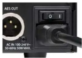
If so, connect the Hilo AC power cord to a grounded AC Outlet, or power distribution unit. Switch on the power switch on the back of Hilo (note: the | position on the power button is “On”)
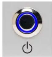
Next press the front panel standby switch and verify that Hilo powers up.
If it does not, verify that the selected AC power source is operational. If it is and the unit still will not power up, please contact Lynx technical support.
If Hilo DOES power up, move on to Set up...
2.2 Set up
Hilo was designed to be adaptable to a variety of operational environments: on a desktop for Audiophile enthusiasts, in an equipment rack for recording studios, over a mixing console for a mastering engineer, etc. If Hilo is to be used on a desktop or other flat surface, it is best to leave the pre-installed rubber feet in place. These are designed to prevent scratching of Hilo or the surface that it is set upon.
In a recording studio context, where space is at a premium, one may choose to rack mount Hilo. The Hilo Rack Kit is available for purchase from authorized Lynx Dealers, or directly from the lynxstudio.com website. The Hilo Rack Kit will include instructions for properly mounting the Hilo.
2.3 Cable Connections
Hilo features a treasury of I/O types, suitable to accommodate whatever audio devices you wish to integrate.
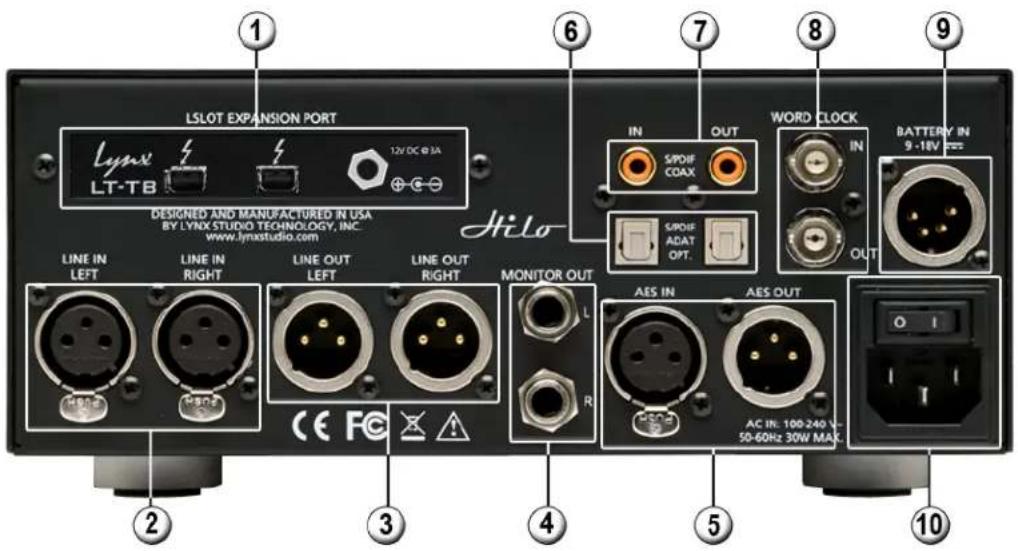
① Thunderbolt port
Use a copper or optical Thunderbolt cable to connect Hilo to a Thunderbolt equipped computer. Cable Concerns: The LT-TB has been tested with standard optical and copper Thunderbolt cables. For Copper cable, one can use lengths up to 3 meters (9.8 feet). Optical cables, while somewhat more difficult to acquire, do promise operation with much longer cable lengths, up to 100 meters.
② LINE IN
Use standard XLR cables (i.e. mic cables) to connect to a line level, balanced signal source. This input is not suitable for use with microphones, unless a microphone pre-amp is used to get mic-level signals up to line-level. Cable Concerns: If your signal source is unbalanced, consult Appendix to determine if your cables are wired correctly for use with Hilo. For unbalanced cables, 4.5 meters (15 feet) is the maximum recommended length.
③ LINE OUT
Use standard XLR cables (i.e. mic cables) to connect to a line level, balanced signal destination. Cable Concerns If your signal source is unbalanced, consult Appendix to determine if your cables are wired correctly for use with Hilo. For unbalanced cables, 4.5 meters (15 feet) is the maximum recommended length.
4 MONITOR OUT
Use standard 14 " cables. TRS if balanced, standard 14 " TS if unbalanced. Cable Concerns: For unbalanced cables 4.5 meters (15 feet) is the maximum recommended length.
⑤ AES IN/OUT
Use AES XLR cables (110 Ω). Insure that the connected device supports AES3 or AES/EBU. Cable lengths of up to 100 meters (328 feet) are acceptable.
⑥ S/PDIF/ ADAT Optical
Use standard Toslink optical cables, of lengths up to 9 meters (30 feet).
⑦ SPDIF Coaxial In Out
Use 75 Ω S/PDIF cable with RCA connections. Recommended maximum length is 6 meters (20 feet)
8 Wordclock In/Out
Use standard 75 Ω wordclock cable with BNC connectors. Recommended maximum length is 9 meters (30 feet).
⑨ Battery In
DC 4-pin XLR battery pack connector. Supports 9-18 volts DC. See Appendix 5.1 for more information.
⑩ IEC Power connector
Use the included AC power cord
In Addition to the rear panel jack pack, there is one remaining cable connection on the Hilo front panel. The PHONES jack is a standard 14 " TRS connector, and is capable of driving the full range of stereo headphones available.
2.4 Initial Setup
It is important to set up Hilo in the proper order to avoid any speaker damage calamities. Follow these steps for the best results:
- Connect the AC power cord to Hilo and to a quality, surge-protected AC power source. Check the Power and Safety section of this manual for additional information.
- Connect cables from Hilo to whatever audio devices Hilo will be connected to. These could include powered speakers, mixing consoles, power amps, microphone pre-amps, effects processors, etc.
- Make sure volumes are turned down on connected equipment to avoid excessive level being sent to the equipment during setup.
- If the context of use is as a standalone AD/DA converter that will not be connected to a computer, skip ahead to section 3, and in particular section 3.4.8: Output Mix Routing Page, for appropriate routing assistance.
- If using Hilo with a Mac or PC computer, follow the installation procedure below.
2.5 Computer Set Up
Hilo/TB should be connected to the computer prior to installing the drivers. If one intends to use multiple Hilos with a single computer, this will be detailed in Section 1.14. For the instructions below, it will be assumed that there is a single Hilo being installed.
2.5.1 Cable Setup
The LT-TB has been tested with standard optical and copper Thunderbolt cables. For Copper cable, one can use lengths up to 3 meters (9.8 feet). Optical cables, while somewhat more difficult to acquire, do promise operation with much longer cable lengths, up to 100 meters.
Thunderbolt cables are somewhat unique in that they contain signal transmission electronics. For this reason it is important to practice good cable management, avoid crimping or allowing cables to be compressed. If such practices are adhered to, these cables should provide many years of faithful service.
Connect a cable from the Thunderbolt port on your computer to either of the ports on the back of the Hilo/TB. Then turn the unit ON.
2.5.2 Driver Installation
Lynx Drivers and firmware updaters are updated regularly. The most current versions can be easily downloaded from the Lynx Website: http://www.lynxstudio.com/ > Support> Downloads. Make sure that you choose LT-TB as the "Product". Choosing Hilo as the product will not give access to the drivers that you will require for this system.
If you are updating an existing driver, the driver installation program will automatically remove the old driver when the new one is installed. When installing drivers, make sure that all software programs, especially audio applications, are closed.
2.5.2.1 Windows 7 (32-bit or 64-bit) or Windows 8
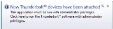
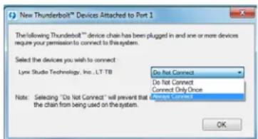
- On first connection, you may receive a prompt that New Thunderbolt Devices have been attached. Click this window to have the system connect to the Hilo as a Thunderbolt Device.
- When the Select Device to Connect Window comes up, Choose "Always Connect". If there are multiple Hilos connected at install time, you will need to do this for each unit. (If this is a reinstall, you will not see this dialog box. Just continue on with the subsequent steps).
- Locate the LT-TB driver from your downloaded files. The file name will be V2Setup##.exe where ## is the build number of the driver.
-
Double-click the installation file to start the driver installation.
-
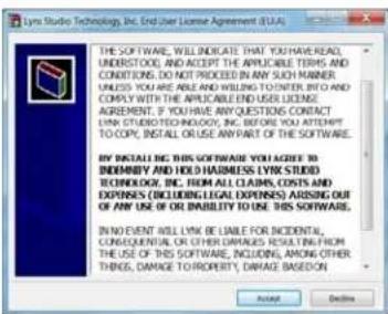
Accept the License Agreement by clicking "Accept"
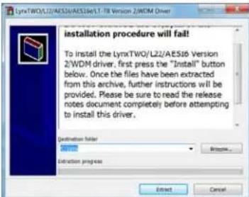
- The installer will extract the necessary files to the C:\Lynx directory. Click "Extract" from this window
-
If you are prompted to let the program make changes to the computer, select "Yes"
-
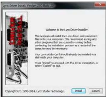
You will next see the driver Install dialog. Click "Install"
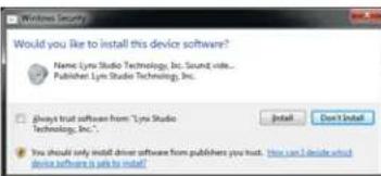
- You may get a Windows Security Dialog Bog. If so, select "Install"
-
Driver installation will proceed
-
Finally you will receive a confirmation that the install completed successfully
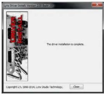
- The Hilo is ready to use, no reboot necessary.
2.5.2.2 OS X
- Locate the LT-TB driver from your downloaded files. The file name will be Lynx_OSX_xxxx.zip. Double-click to expand the installer package.
- Double-click "Lynx OSX.pkg" that was expanded from the step above. This will start the driver installation.
- Click "Continue" at the "Install Lynx CoreAudio Driver Installer" dialog box.
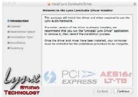
- Click "Continue" for the Software License Agreement after reading it.
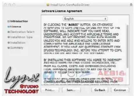
- Click "Agree" from the next Window
- Click "Install" in the Standard Install Window
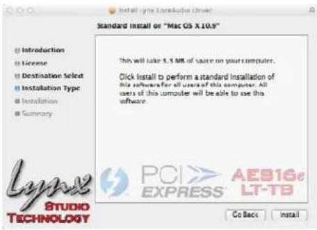
- Type in Password and click "Install Software"
- Click "Continue Installation" for prompt about restarting computer after the installation
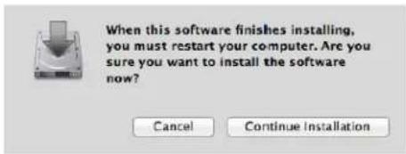
- The installation will continue
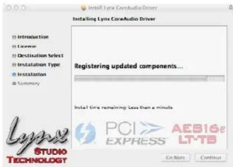
- When complete, you will be prompted to restart the computer
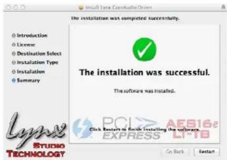
After restart the driver will be installed and ready for use.
2.6 Using Multiple Hilos and/or Auroras
Up to six Lynx Aurora/TB and/or Hilo/TB interfaces can be daisy chained to a single Thunderbolt port. Each unit will be addressable independently, and the combined I/O can be used by a DAW application.
Connecting multiple units requires consideration of the following:
2.6.1 Connect the cables
With the computer OFF, the first step is to connect the Thunderbolt and wordclock cables.
You will need one Thunderbolt patch cable for each Lynx LT-TB Interface in the system.
One cable should be connected from the computer's Thunderbolt port to either port on the first unit. Then daisy chain one at a time, from the open Thunderbolt port on unit 1, to either port on unit 2, out from unit 2 to unit 3, etc. It doesn't matter which port "receives" and which port "sends".
Next we connect wordclock cables to each unit. If Hilo #1 is going to be the clock master, connect a wordclock cable from unit #1 Wordclock Out, to unit #2 Wordclock In, then unit #2 Wordclock Out to unit #3 Wordclock In. etc.
If clock distribution is utilized, a single wordclock cable will go from each Hilo's or Aurora's "Wordclock In" port to an output on the clock distributor. The Hilo and Aurora are self terminating, so there is no need for hardware termination.
Make sure that the wordclock cables are 75 , and as close to the desired length as possible to avoid clock signal phase issues.
2.6.2 Setting Device Order
When mixing Hilo/TB and Aurora/TB interfaces, it is possible to establish the device order for the Aurora units. Information is available about this process from the Aurora/TB manual in section 8.1.2.
2.6.3 Set the Sync Source
Whenever multiple Hilos and Auroras are used in a Thunderbolt daisy-chain, it is critical that clock synchronicity is achieved. In the vast majority of cases we would recommend one of the following clock schemes:
- Use a master clock with multiple clock outputs, ideally as many outputs as there are Hilos in the chain, and connect each Hilo to a unique word clock connection. In this case, ALL of the Hilos should be set to "EXT" as the SYNC SOURCE. In this state, it is important to set the Sample Rate on your clock master, to match the sample rate of your audio file or audio project.
- Use Hilo #1 in the chain, and have the other units slave in a clock daisy chain. Connect a word clock cable from the WORD CLOCK OUT of unit #1, to Clock IN of unit #2, Clock OUT from Unit #2 to Clock IN of Unit #3, etc. Set unit number one to "INT" as the SYNC SOURCE and all of the other units to "EXT". In this state, the system should respond to sample rate changes within the computer automatically.
NOTE: When 3 or more Hilos and/or Auroras are used in a single system, some form of clock distribution is recommended to insure phase coherence of the clock signal.
2.6.4 Configure for use
In Windows, one can use the Sound section of Control Panel to select whichever unit is desired as the default playback device. Unfortunately, Windows is known to jumble the device order here. To determine which unit in the list is the one that you wish to use, follow this process:
* From Control Panel > Sound > Playback, you will see all of the Hilo Devices. Play 1+2 in this list will be labeled as "Speakers". Click one of them to select.
* Click Properties > Advanced
* Click the "Test" Button
* Look at the Hilo Meters. Whichever shows Meter activity for the first pair of channels when "Test" is clicked corresponds to that instance.
* When you determine the desired unit, from the Playback tab of SOUND, right-click that device and select "Set as Default Device".
When using ASIO applications, all of the Lynx Interfaces will be presented as a single ASIO device, labeled "Lynx ASIO". When "Lynx ASIO" is selected as the current audio device, all of the I/O from all of the interfaces will be presented in order. The device order and channel mode of each interface determines its position in the list of I/O. ASIO devices will be labeled with the Device ID, then the Play or Record channels. For instance:
"1: Hilo Play 1+2" is for Unit 1, Channel 1+2
“2: Hilo Play 3+4” is for Unit 2 Channels 3+4 etc.
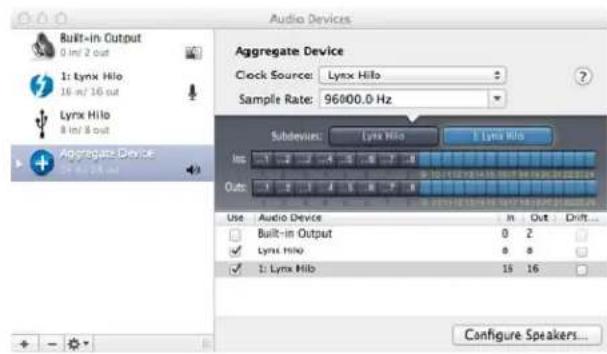
In OS X, all the units must be configured into a single "Aggregate Device" in order for their combined I/O to be accessible to an audio application.
An Aggregate Device is created from Applications > Utilities > Audio MIDI Setup in OS X. Make sure that the Audio Window is open. Click the “+” button at the bottom of the window to create a new aggregate device. You can name it whatever you wish, or accept the default name. Click to check each of the Lynx Interfaces that you wish to be combined into this aggregate device. Up to six interfaces can be added. Make sure that the Drift or Resample box is un-Checked for each selected interface.
Also make sure that the checkboxes for "Built-In" audio are un-checked.
Now, your multi interface LT-TB Aggregate Device is ready to use from within your favorite Audio application.
2.7 Using LT-TB with other Thunderbolt Devices
The Thunderbolt specification requires that certified units can allow for daisy chaining other Thunderbolt devices. Common computer accessories like hard drives, video equipment, and expansion chassis' can be connected to the Thunderbolt Daisy Chain, either before or after your Lynx Interface(s). Up to six devices can be daisy chained together off of a single Thunderbolt port. The Thunderbolt specification also allows for a separate video stream, so that in addition to the 6 devices a monitor can be added at the end of the chain.
2.7.1 Bus Powered Devices
Some Thunderbolt devices operate from Bus Power, where they receive adequate voltage from the Thunderbolt connection to drive the device, as an alternative to having a dedicated power supply. The LT-TB does support such devices, but it is necessary to connect a 12V DC power supply to the LT-TB card prior to running such a device. The appropriate AC Adapter is available from Lynx dealers, or directly from the lynxstudio.com website. The part number is LYN-ACPS1000.
When connecting a bus-powered device, connect the AC adapter to the 12V DC port on the LT-TB equipped interface that precedes the bus-powered hardware in the Thunderbolt daisy chain.
3 Using the Hilo/TB
With the LT-TB correctly installed in your computer, you can begin to use the Hilo with most popular third-party audio applications. In this section we will explore setting up the Hilo/TB system for different contexts of use.
3.1 Hilo Driver Devices – Windows Operating Systems
Hilo was designed to provide maximum compatibility with the most popular audio and multimedia applications that use the Windows MME, DirectSound, ASIO and OS X Core Audio driver standards. It is crucial that the applications are set up correctly for optimal operation.
The Windows drivers for the LT-TB support two dominant driver models, WDM (which include both MME and DirectSound) and ASIO.
WDM was developed by Microsoft and is used most typically by media playback applications, such as Windows Media Player, iTunes, Quicktime Player, WinDVD, PowerDVD, etc.
ASIO was developed by Steinberg, and was designed to address the low-latency and high channel count needs of Pro Audio and Music Production. ASIO is an option for Audio Production applications such as Pro Tools, Cubase/Nuendo, Sonar, Samplitude/Sequoia, Audition, etc. These applications may also support MME or DirectSound, but when the option exists, we recommend using ASIO for the best performance.
3.1.1 WDM/Multimedia Applications
Hilo can be used as a playback device for most popular multimedia, home theater and consumer audio applications. Some such applications allow selection of specific playback devices. In these cases, 8 Hilo stereo play devices will be available to choose from. These devices are labeled as TBT Play 1&2; TBT Play 3&4; TBT Play 5&6; TBT Play 7&8; TBT Play 9&10; TBT Play 11&12; TBT Play 13&14; TBT Play 15&16. It is generally advisable to choose TBT Play 1&2 with any WDM program. This will insure that audio streams to every analog and digital output on Hilo. If you wish to mute a stream to a particular output, you can do that from the Output Mix Routing Page, as described in section 3.4.8 Output Mix Routing Page.
When output device selection is not an option, it can be assumed that the application uses the Windows default audio device. In this case, “Lynx TBT Play 1&2” should be established as the system playback default:
With Windows Windows 7 / Windows 8 navigate to:
Start > Control Panel > Sound > Playback. Right-Click on “(Speakers) LT-TB” and choose “Set as default device”.
3.1.2 ASIO Application
When using an application that supports the ASIO driver standard, one must specify the Lynx ASIO driver as the active audio device from within the audio software. Once that is established, eight stereo input and output devices will be available for use within the application.
When using an ASIO compatible program, the appropriate ASIO device must be selected from a settings or options menu in the application. The correct choice would be “Lynx ASIO”
Many ASIO applications provide access to an ASIO Control Panel for the device being used. For an LT-TB equipped Hilo, this button will launch the Lynx ASIO Control Panel.
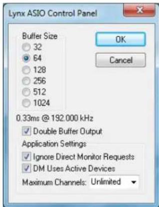
From this panel, the ASIO buffer size and system latency can be established conveniently within the audio software application. The following parameters can be altered from the Lynx ASIO Control Panel:
-
Buffer Size - This control allows the size of the ASIO buffer in samples to be established. The buffer size is the primary factor in the amount of latency that a user will experience when using the Hilo/TB. In the next section this is explored in depth.
-
Latency – Displays the amount of latency in milliseconds that is the result of the selected buffer size at the active sample rate.
-
Double Buffer Output – When checked, an additional output buffer is used. This does increase playback latency, but relieves some strain on the CPU. It is ON by default and recommended, especially if any performance issues are encountered.
-
Ignore Direct Monitor Requests - This switch causes the LT-TB driver to disregard Direct Monitor commands from an ASIO software application. Since Direct Monitor calls can assign and mute monitor sources in the Hilo, setting this parameter
to "ON", can prevent mixer settings from being changed when an ASIO application is launched.
- DM Uses Active Devices - This switch sets the Direct Monitoring scheme for the application. When unchecked, all devices (active or not) may be used for Direct Monitoring. When checked, only active devices, or devices assigned to software busses, are used for Direct Monitoring. This gets around a problem where Cubase & Nuendo might select the wrong Direct Monitoring input or output if non-contiguous devices are active.
This switch is ON by default for Nucendo 2 & 3 and Cubase 2 & 3 and OFF by default for all other applications.
- Maximum Channels – This switch determines how many ASIO device channels will be available to the application. This is an application specific parameter. If different ASIO applications are used at different times, it is possible to have them set differently.
The primary purpose for this switch is to increase CPU efficiency and to facilitate multi-client operation. The default state is “unlimited”, which means with a Hilo/TB 8 stereo devices.
Most audio software allows the user to specify how many ASIO devices are used, generally in a settings or options menu. There are some applications however that grab control over ALL of the ASIO devices in the system. This can be problematic because it uses more CPU power than is necessary, and also because there are no driver devices available to be used by another application (multi-client operation).
In these cases, setting the MAXIMUM CHANNELS switch to the desired number of channels, frees up some CPU overhead, and allows another application to access the channels that the ASIO application is not using.
3.1.3 Controlling Latency by Changing the Buffer Size
Latency in an audio interface can be defined as the time required to process a sample from an application to the interface's audio output. A number of factors determine the achievable latency performance of a Hilo/ TB system: processor speed, operating system, sample rate, number of utilized record or play channels, system efficiency, etc.
Latency can be manipulated by changing the size of the buffers used to transfer data to and from the LT-TB. The higher the buffer size, the less work the computer has to do to stream audio to the hardware. However, a higher buffer results in more latency. Also, the higher the sample rate, the higher the buffer size needs to be. For instance, a buffer size of 128 samples at a sample rate of 44.1 kHz results in 2.9 milliseconds of latency. However, at 96 kHz, a buffer size of 128 = 1.33 milliseconds. Therefore the buffer size needs to be increased as the sample rate increases to maintain the same level of performance. If the buffer size is too low, you can experience clicks, pops or distortion in the audio. This is the result of buffer under-runs, when the audio buffer is momentarily depleted because the computer cannot deliver samples quickly enough to keep it filled.
Why is latency important? It isn't in every case. Here are the main conditions where low latency is important:
* Software input monitoring. This is where you are monitoring through your audio software the input signals to be recorded. The software is re-directing the input signal back out to a play device. If the buffer is too high here the performer will hear a noticeable delay between the notes they are playing and hearing the sound back through the computer. With Hilo, zero latency hardware monitoring is available as an alternative to software monitoring. See Section 3.4.8: Outputs Mix Routing Page.
* Virtual Instruments. Generally this would involve using a software synthesizer or other virtual sound source as an alternative to dedicated hardware like a keyboard or tone module. Frequently one would play these instruments with some sort of MIDI controller. The delay between a key being struck and hearing the resulting note from the virtual instrument is a function of latency.
* Mix Automation. Virtually all DAW applications feature some sort of Mix Automation, and most allow an external Mix surface or MIDI controller to facilitate mixing within the software environment. Whether using onscreen faders or a MIDI surface of some sort, latency will determine the delay between manipulating a fader or knob, and that move being reflected in the project.
3.2 Hilo Driver Devices - Macintosh OS X
Hilo will operate as a Core Audio device under OS X after the driver has been installed. Core Audio is the dominant audio driver model for OS X, and is used for media playback applications as well as Pro Audio applications.
3.2.1.1 OSX Audio Applications
Hilo can be used as a playback device for most popular multimedia, home theater and pro audio applications. Some such applications allow selection of specific playback devices. In these cases, a Lynx Hilo TBT output device can be selected from the appropriate device selection menu.
In cases where the playback software does not provide access to output selections, the default output devices for the operating system will be used. In OS X, the audio out default device can be established from Applications > Utilities > Audio MIDI Setup.
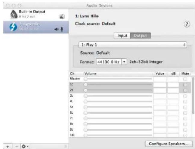
When the Lynx Hilo is selected as the output sound device, channels 1&2 are active by default. In this state, audio will be sent to ALL Hilo outputs simultaneously. If you wish to mute a stream to a particular output, you can do that from the Output Mix Routing Page, as describe in section 3.4.2 Output Mix Routing Page.
3.2.1.2 Controlling Latency by Changing the Buffer Size
Latency in an audio interface can be defined as the time required to process a sample from an application to the interface's audio output. A number of factors determine the achievable latency performance of a Hilo/LT-USB system: Processor speed; Operating system; Sample rate; Number of utilized record or play channels; System efficiency; etc.
Latency can be manipulated by changing the size of the buffers used to transfer data to and from Hilo. Core Audio buffer size controls are offered within most pro audio recording applications. With Hilo, buffer sizes typically range between 32 and 2048 samples.
Smaller buffer sizes will give you lower latency. However, if a buffer size is too small for the system or context, audio anomalies such as clicks and pops may occur. It is recommended to become familiar with altering the Hilo buffer size to best suit the context of use.
Once you determine the lowest achievable buffer size, you will typically have to double the size each time you double the sample rate, but the effective latency will remain constant. For example, if a system is capable of operating at a buffer size of 128 samples at 48 kHz, then for a 96 kHz project, the buffer size will likely need to be increased to 256 samples.
3.3 Firmware Updates
Hilo contains firmware that is field-programmable via the Thunderbolt connection. These updates improve performance and enhance functionality of Hilo. In some cases, the touch screen functions and appearance may change dramatically from firmware updates.
Additionally, the LT-TB card installed into Hilo has its own firmware. There are also updates for this card available that, similarly, can improve functionality and expand the feature set. Updaters for both the Hilo and the LT-TB running
on Windows and OSX can be downloaded from the Lynx Studio website. Here are the steps to insure that your Hilo is up to date and in top form:
-
Make sure that your Hilo has a valid Thunderbolt connection to the computer. It is essential that current drivers are installed and operational.
-
Visit www.lvnxstudio.com and click Support > Downloads.
-
Select your OPERATING SYSTEM from the list, "Hilo" as the PRODUCT, and "All Types" for FILE TYPE. Click "Search"
-
Download the Hilo Firmware Updater. Double Click to launch it.
-
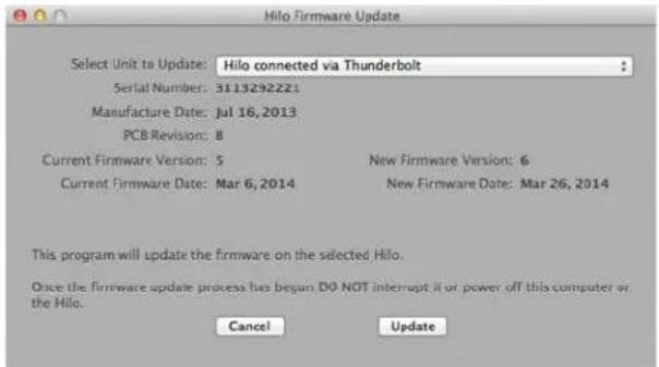
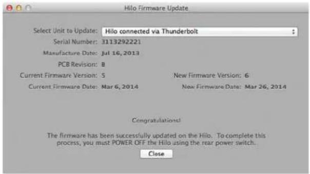
Follow the prompts (Windows Users need to accept the EULA) until you reach the Hilo Firmware Update screen. Verify that the "New Firmware Version" is higher than the "Current Firmware Version". If so, click "Update".
-
The Hilo LCD screen will display a warning screen that reads "Do not turn off the computer or the Hilo during the firmware updater process". There is also a progress bar.
-
Follow the prompts. When the Update is complete, you will be instructed to power down Hilo. Turn off the front panel standby switch. Then turn off the rear panel power switch. Wait three seconds, then power Hilo back up.
-
Now we need to update the LT-TB card inside of Hilo. Again visit www.lynxstudio.com. Select your OPERATING SYSTEM from the list, "Lynx LT-TB" as the PRODUCT, and "All Types" for FILE TYPE. Click "Search"
-
Launch the AES16e/LT-TB Update application.
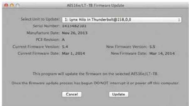
- Verify that the New Firmware Version is higher than the Current Firmware Version. If so, click "Update"
- Follow the prompts. When the updater is complete, you will be prompted to turn the computer off (not a reboot). Click "POWER OFF" and the computer will be shut off automatically. Wait three seconds, then turn the computer back on.
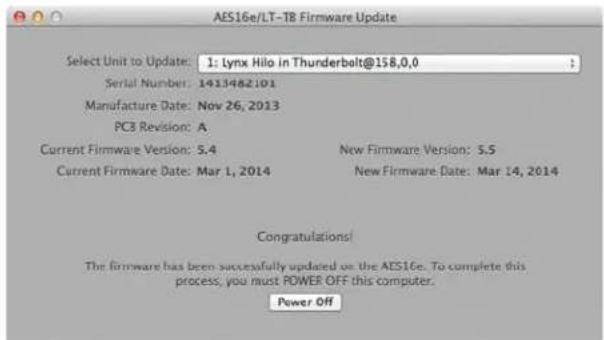
- The new LT-TB firmware will now be active.
Also after programming, the settings you had on the unit previously, including saved scenes, may need to be re-established. This depends on the number and type of differences between the older firmware and the newer.
4 Controlling Hilo
Hilo's Touch Screen gives it a key advantage over other converters. As all of the functions are controlled by the software that runs the touch screen, Hilo is not locked into just one way to work. We can add features. We can change the graphics. We can offer completely different user interfaces for different types of users. So the Hilo user interface in five years may be radically different than today's Hilo. In short, it will evolve. You can help us with this. As you have ideas, suggestions, complaints, comments, send them to hilo@lynxstudio.com. This email will go to the engineering, marketing and support staff who built this interface.
Hilo was designed for case of use, without navigational clutter on the front panel.
The heart of the Hilo system is the 480 x 272 pixel front panel touch screen. This is where settings, routing, volume control and meters are displayed and managed. The Hilo screen is responsive to pressure. It may take a little getting used to the amount of pressure and accuracy required for the on-screen buttons to respond. Also, like any such device, Hilo employs navigational conventions that, although designed to be intuitive and require little or no explanation, may require a small learning curve initially.
4.1 On Power Up
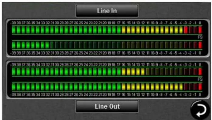
Upon turning on Hilo, the first screen that you will see will be the METER page that was last selected when the unit was turned off. The dual Horizontal Meter set is shown below.
4.1.1 Headphone and Monitor Out Volume Control
If you turned Hilo off using the STANDBY switch on the front panel, all of your previous settings will be recalled. Your Headphone and Monitor Out levels will be the same as when you last used them.
Caution: Be sure to check the volume level of the Headphone and Monitor before playing audio. You can do this by simply turning the Rotary Control. A level indicator will appear at the bottom of the screen. The Hilo PHONES Output has "jack sense", so that the headphone volume controls are only available when headphones are plugged in. If headphones are not plugged in, then the Rotary Encoder will only control the Monitor Out level. If headphones are plugged in, then pushing in the Rotary Control knob will allow you to toggle between
Headphone and Monitor Out Volume Controls, or any three outputs selected in the "Knob Settings: menu. See section 3.7.6
4.2 Changing the Meter Page
At this time there are three metering options:
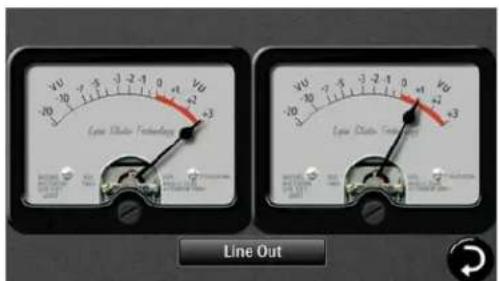
Analog VU Horizontal Bar Style
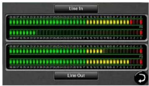
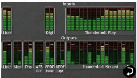
All I/O
To change the meter type, tap the meters on the screen, and the Meter Type menu will appear:
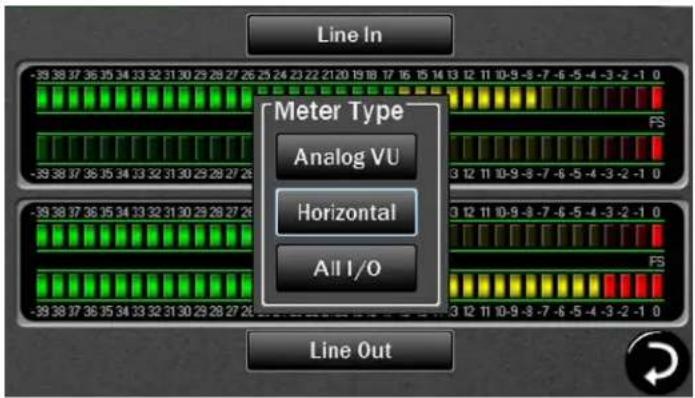
Touch on the type of meter you would like to see. The new meter will instantly appear. If no selection is made, clicking anywhere on the Touch Screen outside of the menu will cause the menu to close.
4.2.1 Choosing the Meter Source
You can select any Input or Output Source to be shown on the Analog VU and Horizontal Meters.
4.2.1.1 For the Analog VU Meters:
Touch the Monitor Source Selection button that is centered at the bottom of the screen. Before touching the button, it will show the current selection. A Pop-up will appear with two sets of input sources on the left and six sets of output sources on the right.

Tap on the input or output source you need. The meter will reset and the Pop-up will close. The Monitor Source Selection button now shows your new selection. The Pop-up will remain on the screen until you either make a selection, or tap outside of the menu in order to close it.
4.2.1.2 For the Horizontal Meters:
This is the same process, but you can select different sources for each meter pair.
Touch the Monitor Source Selection button that is centered at the top of the screen for the upper meter set or the Monitor Source Selection button that is centered at the bottom of the screen for the lower meter set. Before the buttons are pushed, they will show the current meter selection. A Pop-up will appear with two sets of input sources on the left and six sets of output sources on the right. These are the same options as for the Analog VU meters. Tap on the input or output source you need. The meter will reset and the Pop-up will close.
Use the same procedure for the other meter set. . The Pop-up will remain on the screen until you either make a selection, or tap outside of the menu in order to close it.
4.2.1.3 For the All I/O Meters
With the All I/O meter page, no selection is needed as all input and output sources are shown. The All I/O page is useful for different reasons. When setting up your routing (explained later) this page gives you a global view of what input channels are active and which outputs are receiving audio from at least one source.
4.3 Getting to the Menu Pages

The in the lower right corner of any Meters page will send you initially to the Home page. Thereafter this will send you to the last Menu page that you accessed.
The bottom of the menu pages has five round buttons which allow you to navigate between menu pages.
natural_image
Five black circular icons representing computer, monitor, information, wrench, and house (no text or symbols)The Meter button on the far left returns you to the active meter page. The four buttons on the right select menu pages, each with up to 8 functions.
These five buttons, when pressed, bring up the following pages:

Meters Immediately changes the screen to the last selected meter set.

Display Allows settings that customize the information and format of the LCD Screen.

Information Displays useful status about Hilo and its operation

Tools Scene/routing memory and other, well, tools.

Home Basic settings and routing.
4.3.1 Menu Screen conventions:
When you engage a button, it "lights up", just as if you are pushing a button on a console. The last button touched or changed will always light up when that Menu page is selected.
Most buttons have a dual purpose. First they display the control's current setting. Second by touching them, you can select a different setting.
4.4 Home Menu
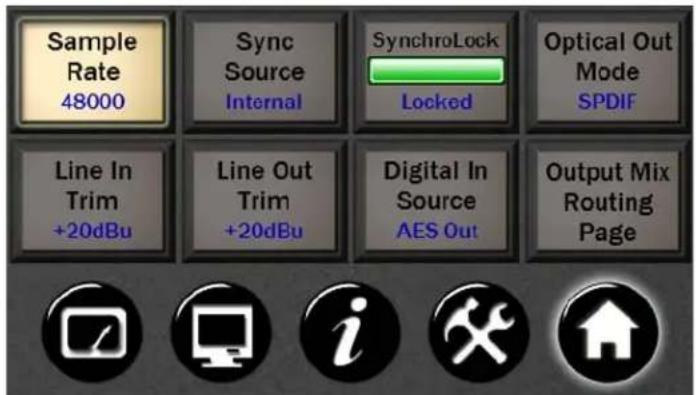
4.4.1 Sample Rate
Hilo will display the sample rate that it is currently operating at. If clocked externally, this may be the sample rate being generated by the clock source. If clocked Internally, the sample rate may reflect the rate of audio being played or the rate requested from an audio software application.
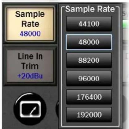
If Hilo has the Sync Source set to Internal, then one can manually choose a sample rate by pressing the Sample Rate button and tapping on the desired rate. If Hilo has a valid Thunderbolt connection to a computer, the sample rate can be established from within the computer's sound settings OR from the Hilo SAMPLE RATE selection button. When setting the rate from the Hilo, it is advisable to have no audio applications open, because a sample rate change can cause an audio application to crash or malfunction.
4.4.2 Sync Source
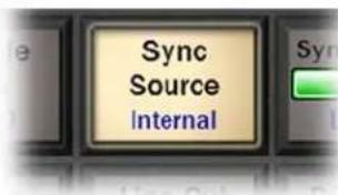
This button will show the currently selected Sync Source.
When you push the Sync Source button, you may select any of six possible clock sync options. If a clock source is valid, a sample rate will appear next to that selection. For instance, if a clock source is connected to the Hilo word clock input, next to "Word Clock" there would appear the sample rate that the clock source is generating. Also, it is best to have open audio applications closed when changing the SYNC SOURCE from the Hilo display.
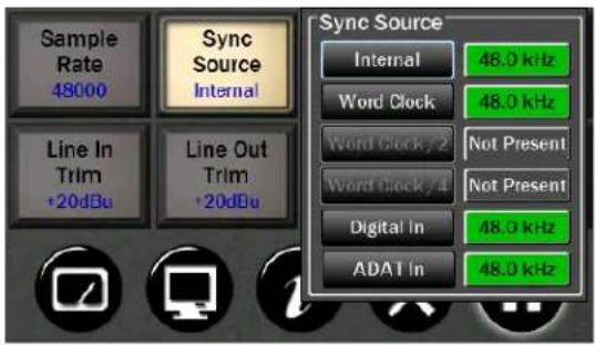
Hilo Sync Source may be changed to one of the following four choices:
- Internal: Clock driven by the Hilo's crystal oscillator
- Word Clock: Clock derived from the WORD CLOCK input
• Digital: Clock derived from the active digital input - ADAT In: Clock derived from the ADAT input. Once an ADAT signal is detected on the Optical Input, Hilo automatically switches the Optical input from S/PDIF to ADAT. In this mode, the additional ADAT inputs will appear as available channels on the output mix routing page; meter source selection and the test tone page.
Please note that Word Clock/2 and Word Clock/4 are not available in version 6 firmware.
The box next to each clock source will display the clock rate when that port has a valid clock source attached. If that clock source is selected, that rate will become the current clock rate for Hilo. If Hilo detects that a specific Sync Source is not valid, that Sync Source button will be disabled and "Not Present" will be displayed next to it.
4.4.3 SynchroLock
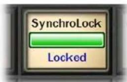
Lynx's SynchroLock™ technology is a very effective form of jitter reduction for digital signals. Jitter is a type of clock error that may potentially result in distortion in an audio signal. SynchroLock reduces jitter by a factor of 3000:1 by using the Hilo's high resolution crystal oscillator to generate a clock signal that is phase locked to the external clock.
Compare this to attenuation of 100:1 or less for professional quality analog phase-lock loops (PLL) that are used by most Pro Audio devices. As long as the clock frequencies are within +/- 100ppm of Hilo's supported sample rates, SynchroLock will operate on the clock signal, and insure a low-jitter clock drives the Hilo and is also sent to devices downstream (i.e. clock slaves to the Hilo).
The SynchroLock operation is a two-stage process, starting with a fast-locking analog PLL to insure that there is clock sync immediately when a Sync Source or Sample Rate are selected, and concluding with the digitally controlled crystal-based secondary stage. It is normal for SynchroLock to take 1-2 minutes to achieve full lock.
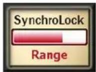
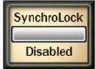
There are four possible states for the SynchroLock button.
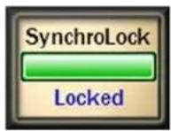

Locked
Either Hilo is operating off of its Internal clock, or SynchroLock has achieved full lock to the specified external clock source. In this state, playback and recording of audio is possible
Working
Hilo is operating off of its Analog Phase Lock Loop to lock to the incoming clock signal, while the SynchroLock circuitry is performing analysis on the incoming clock signal. This may continue for 1-2 minutes. In this state, recording of audio is discouraged. Playback is acceptable, but it should be noted that there will be an audible glitch the moment that full lock is achieved. "Working" will occur every time a new Sync Source or Sample Rate is selected unless SynchroLock has been disabled or the Sync Source is set to Internal.
Range
This indicates that the selected external clock signal is operating outside of SynchroLock's usable range. If this state is persistent, it is advisable to stop using the clock source responsible.
Disabled
The SynchroLock circuitry has been disabled by the user. In this state, the Hilo will only clock via the Analog PLL when external Sync Sources are chosen. Pressing the SynchroLock button will toggle between Enabled and Disabled. Generally, disabling SynchroLock is not recommended for the best performance.
4.4.4 Optical Out Mode
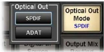
Hilo's Optical inputs and outputs can be used for either stereo SPDIF or 8 channels of ADAT (at 48 kHz). Hilo also supports the S/MUX protocol for ADAT Lightpipe operation at higher sample rates. The ADAT Ports support 4-channels at sample rates of 88.2/96 kHz, and 2-channels at sample rates of 176.4/192 kHz.
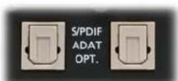
Output on Right.
This button shows the currently selected status of the Optical Output and allows the selection of either S/PDIF or ADAT. Pushing the button brings up the Pop up window to change the Optical Out mode.
4.4.5 Line In Trim
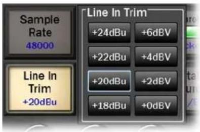
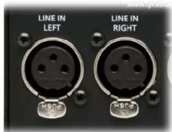
Line In Trim can be set to any of eight preset trim settings. The Line In Trim button shows the currently selected trim level, the same for the Left and Right inputs.
There are four Pro Level settings: +18 dBu; +20 dBu; +22 dBu; and +24 dBu. There are four additional levels most often used on Consumer Audio products: +0 dBV; +2 dBV; +4 dBV and +6 dBV.
When the button is pushed, a Selection Window pops up. Pushing the desired Level button resets the inputs and immediately indicates this on the Line In Button. You will typically hear a relay click from inside Hilo when a selection is made.
Note: These are 0dBFS (full-scale) level settings, as opposed to nominal levels.
Trim pots are available to fine tune these inputs. See Appendix 5.2 for more information.
4.4.6 Line Out Trim
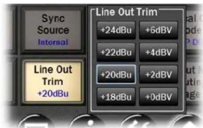
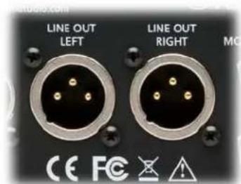
Line Out Trim can be set to any of eight preset trim settings, the same as for Line In.
This works exactly the same as the Line In Trim. Push the button and make your selection.
Note: Each Line In and Line Out Trim can be adjusted ±0.5 dB of the established trim settings using the trim pots that are located on the bottom of the circuit board. See Appendix 5.2 for more information.
4.4.7 Digital In Source
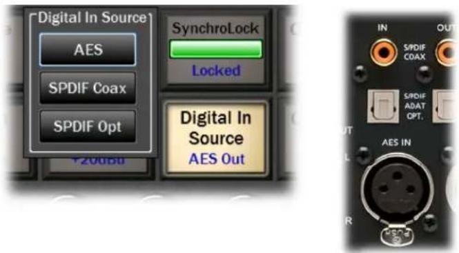
Hilo offers a choice of AES or S/PDIF as the digital input source. With S/PDIF you have the option of Coax or Optical Inputs.
Before being pushed, this button shows the current selection. Upon pushing the button, you can select: AES; S/PDIF Coax; or S/PDIF Optical. If selecting SPDIF Optical, the Optical Out mode must be set to SPDIF. See section 3.4.4.
Note: You do not need to make this choice for outputs, as all three digital outputs are independently available and assignable.
4.4.8 Output Mix Routing Page
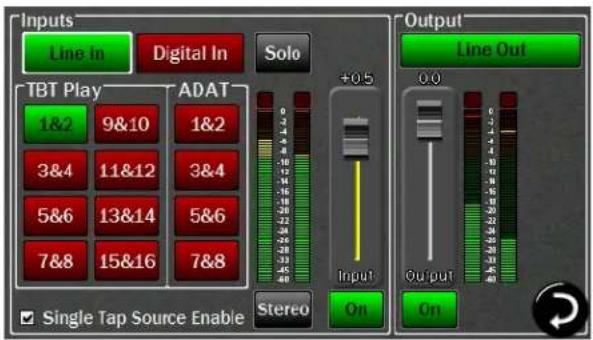
Now this is where it gets interesting. Although Hilo is, at first glance, a two channel AD/DA converter, it is really much more and this page gets down to the nitty gritty.
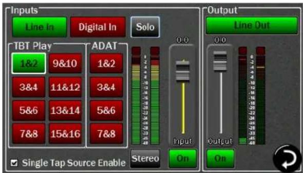
The Output Mix Routing page is where any combination of Hilo's inputs can be routed to any combination of Hilo's outputs. The principle here was to make the various I/O formats as independent as possible, very little is "hard-wired". This is not simple point-to-point patching. Multiple sources can be merged to a single output. Levels can be set and adjusted for all input sources and outputs. Sources can be mirrored to multiple outputs. Sources and outputs can be muted. This is why Hilo has an internal 32 x 32 channel mixer. This is where you get to use it. First a few conventions:
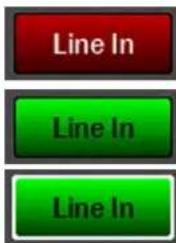
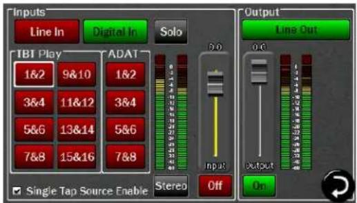
RED buttons mean that the associated signal source or output is OFF or MUTED
GREEN buttons mean ON or UNMUTED
A WHITE LINE around a button means this is the channel is in focus, and can be acted upon by the faders or ON/OFF switch below the fader.
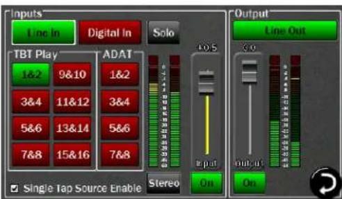
As you can see, the page is divided into input sources on the left and outputs on the right. What we are seeing here is which input sources are assigned to the displayed output. We are not turning inputs On and Off, we are turning the connection between an input and output On or Off. Think of it as a patch cable.
The ON/OFF button on the Inputs side patches that input source to the active output. On the Output side, the On/Off button mutes or un-mutes the selected output.
With the Graphic above, we see that Hilo TBT channels 1&2 being and the Line In are both routed to the Hilo's Line Out.
4.4.8.1 Monitoring Modes
The default state for each input source is stereo, with two channels of input, streaming through a two-channel output.
There are 4 different options for routing an input signal to an output. These selections pertain to the operation of a specific input source routed to a specific output. The setting is not global, and must be set for each output that is being used.
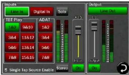
Select the Output channel that you wish to listen to, then press the desired input source (in this example, Line In).
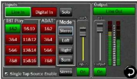
Then tap the Stereo button under the input meters. You can now choose between:
- Stereo (default)
- Left –audio from the Left input channel (in this case Line In Left) streaming to both output channels
- Right – the Right input channel streaming to both output channels
- Sum – combining both the Left and Right inputs into one Mono stream which is sent to both the Left and Right outputs equally. The summed signal is automatically attenuated by 6dB in order to reduce the possibility of digital clipping.
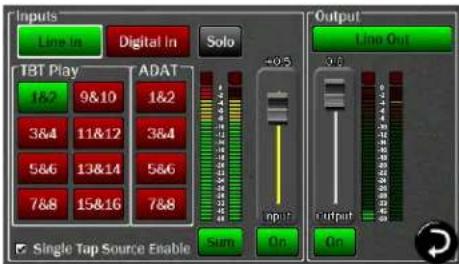
The chosen option is shown on the button at the bottom of the Input meters any time that input channel is selected.
Each input channel can be controlled and assigned independently for each output.
For example, you can have Line In "Summed" sent to the Monitor Output, while having Line In "Stereo" assigned to the Headphone Output. This flexibility allows complex routing to be achieved very easily.
4.4.8.2 Solo Button
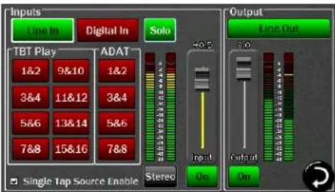
The Solo button allows any active input channel to be isolated. This allows very rapid comparison of sources, A/B switching, and a convenient way for troubleshooting audio anomalies.
Simply press the Solo button and it will engage and turn green with the word "Solo" blinking.
In this state, press any input source button and you will hear that audio exclusively. Pressing any other input source will instantly switch to the alternate source.
When done, tapping the Solo button returns Hilo to the previous state, where multiple input sources can stream to an output simultaneously.
4.4.8.3 Input Sources
This is for signals from the Analog Line In ports.
Of the three stereo digital formats: AES, SPDIF Coax and SPDIF Optical, only one can be active at a time. This is selected from the "Digital In Source" button from the Home menu.
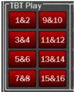
These sources correspond to Thunderbolt play devices that will appear in the host computer. Unlike most computer audio interfaces, with Hilo these sources are user routable for maximum flexibility.
Upon installation, each pair of computer play devices will be pre-assigned to physical outputs on Hilo. In addition, the first channel pair, Hilo TBT Play 1+2, will deliver audio to every output on Hilo. This is very useful for initial set up, whether you are listening to the headphone out, a digital out, monitor outs, whatever – you will get audio when you choose 1+2 as the play device.
If a valid ADAT lightpipe signal is detected on the optical input, then the ADAT inputs are visible and available in stereo pairs.
The Default TB play routings are:
Line Out: TBT 1+2
Monitor Out: TBT 1+2 and 3+4
Phones:
TBT
1+2
and
5+6
Digital Out XLR (AES): TBT 1+2 and 7+8
Digital Out Coax: TBT 1+2 and 9+10
Digital Out Optical: TBT 1+2 and 11+12
ADAT Out 1-8: TBT 1+2 and 9-16
4.4.8.4 Outputs
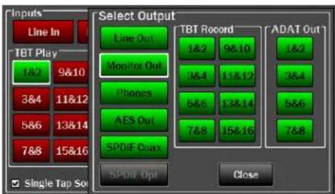
You may have noticed that, with the exception of the TBT play channels, all input sources are muted/off by default. The output sources are the opposite, all un-muted/on by default. To select an Output to assign input sources to, to mute, or to control its level, press the Output Selection button to reveal the Select Output menu:
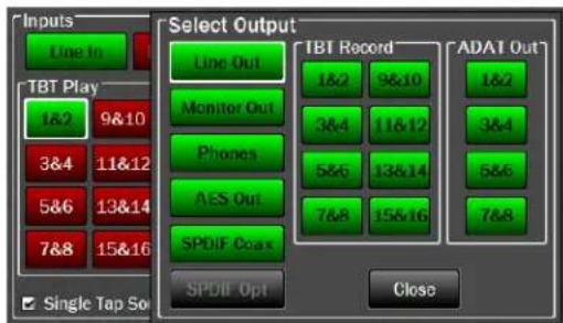
Outputs are labeled clearly for selection.
Unlike with input sources, all three digital outputs are individually selectable, as are the ADAT Outputs
Please note, if the Optical Out Mode on the Home menu is set to SPDIF, then the ADAT outputs will not be shown and cannot be selected. If the Optical Out Mode is set to ADAT, then the SPDIF OPT option will be grayed out and cannot be selected.
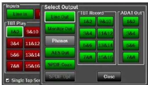
The Hilo Headphone Jack also has "jack sense" and can appear dynamically. When headphones are connected to the front panel Phones jack, then Phones is selectable as an Output choice. If headphones are NOT connected to the Phones jack, then the Phones selection is grayed out and not selectable (pictured).
The Hilo Record devices correspond to the input options that will appear in OSX or Windows recording software. As with the Hilo Play devices, there are default settings of Hilo inputs that stream to these record devices:
Unassigned: TBT Record 5+6 and 7+8
ADAT In 1-8 TBT Record 9-16
One may note that Hilo TBT Play devices can be routed to TBT record devices. This has interesting possibilities for anyone who wishes to record playback streams in the computer. For instance, one can be playing audio from the internet and record it into their DAW.
4.4.8.5 Analog and Digital Level Controls for Monitor and Headphones
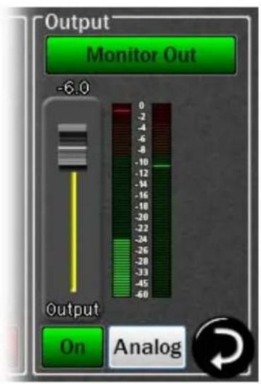
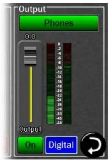
When the Monitor Out and Phones Outputs are selected in the Output Mix Routing Page, you will see an additional button. For these two outputs you can control both the Digital output level and the Analog output level.
Analog Output Level – This is your primary monitoring level control. You can control this level / volume using the fader or the knob on the front panel.
Digital Output Level - Your default for this level is all the way on, at 0 dBFs. This provides the best possible signal to noise ratio, and therefore the best audio quality.
However, since Hilo offers you the option of routing several inputs to these outputs, you may overload the digital output and cause distortion. When this is the case, use the Digital Output control to lower the level feeding the D/A converter. Note, this control is NOT for setting the volume level of the Monitor or Phone outputs, but to attenuate the digital signal to reduce distortion. Once the digital overload has been lessened, you can set the listening volume with the Analog level control.
There is an overload at indicator at the top of these meters. When potentially distortion-causing clipping occurs, this indicator turns red and the associated text reads “OVER”. For an input, the Over indicator will activate when there are three full-scale samples in a row, which indicates a high probability that clipping has occurred. For the outputs, the Over indicator is an accurate reflection of an actual overload condition and the attenuation should be performed on the input sources or digital outputs themselves when this occurs.
Before we explore how to route sources, we need to take a look at the “Single Tap Source Select” button, because this impacts the way that sources are enabled.
4.4.8.6 Single Tap Source Select
One of the advantages of the Touch Screen GUI, is that we can offer user-preferred options for the way onscreen buttons behave, a big advantage over standard, fixed-function hardware buttons. This is one such option.
- For this parameter, Checked is the default. In this state, pressing an INPUT source button will instantly turn that source OFF to ON or ON to OFF, the same function as the ON/OFF button below the fader. This allows for quicker one-touch selection and muting of INPUT sources. However, the selected source will be present instantly with full volume on first press or a previously set volume level.
- When Unchecked, pressing an input source will only bring that source into focus. One must then press the ON/OFF button to make the source active. The advantage is that you would have the opportunity to adjust the level of that source before it is sent to the output. This mode would be typical for live use, where making an input source live at full volume could have ear-shattering consequences.
For the remainder of this section, when mention is made of enabling sources whether this is accomplished by the Single Tap method (Single Tap Source Select = ON) or Two Tap (Single Tap Source Select = OFF) will be left up to the reader.
4.4.8.7 Selecting Monitor Sources
Let's look at the process of assigning input sources to Hilo's Outputs
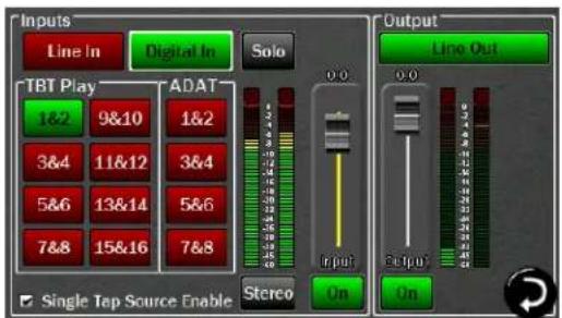
Let's say that we wanted to add Digital In as a source to route to the Line Out.
We could simply enable the Digital In with either a single-tap or double-tap and the page would now look like this.
In this state, audio streaming from TBT Play 1&2 will be merged with audio streaming from the Digital Input. One must be cautious of the levels of each source in this case, as the combined signal strength could cause clipping to the output. If this occurs, it can be remedied by attenuating the faders for the input sources (TBT Play 1&2 and Digital In), or by attenuating the associated output.
Now if we wish to listen to the Digital In signal through Line Out but NOT the TBT Play 1&2 signal, we could turn the Hilo Play 1&2 button off, again via the one-tap, or two-tap method.
Using either method, the result would be Digital In as the only source feeding Line Out. It would look like this.
4.4.8.8 Adjusting levels of input sources and outputs
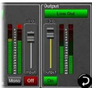
The Output Mix Routing page has two faders, one on the input side and one on the output side. In both cases the single fader controls the level for two channels of audio.
The fader on the input side adjusts the amount of signal from the input source that is in focus (with the white box around it) that is feeding the active output. It is not altering the input level itself (Hilo does not do this for sonic reasons), merely the amount of that input signal streaming to the output. This fader has a range of -95 to +12 over unity. The associated meter displays the input signal strength, so there will be no decrease in meter activity as the input source is attenuated.
The output fader adjusts the overall volume level of the output selected. With Monitor Out and Phones Out, the fader will adjust the ANALOG output level by default, ensuring the best sonic results. In cases where the listening level is correct, but there is clipping on those outputs because multiple sources are being summed together, the fader function can be switched to digital by pressing the Analog/Digital selection button in the output section. With this option, one can eliminate clipping from the digital side, and then adjust for the desired listening volume on the analog side. With all other outputs, the fader attenuates digitally. The output fader adjusts from -96 to unity.
There are two means to adjust the input source and output faders.
They can be adjusted directly on the touchscreen or with greater accuracy by using the rotary encoder knob. When the knob is used, pressing down will toggle the active fader from Input Source to Output.
The active fader will have a yellow fader track. In this graphic, the Output is the active fader.
4.4.8.9 Routing tutorial
These powerful routing features are probably best demonstrated with a real-world scenario. Let's pretend that the Hilo is being used for a recording session, where a keyboard part is being overdubbed on an existing project. The pre-recorded tracks are streaming through the TBT Play 1&2 channels in the computer.
For cable connections, the keyboard signal is coming in LINE INPUTS 1&2. The recording engineer is listening to the MONITOR OUTPUTS feeding speakers in the control room. The performer is listening to headphones plugged into Hilo's PHONES jack.
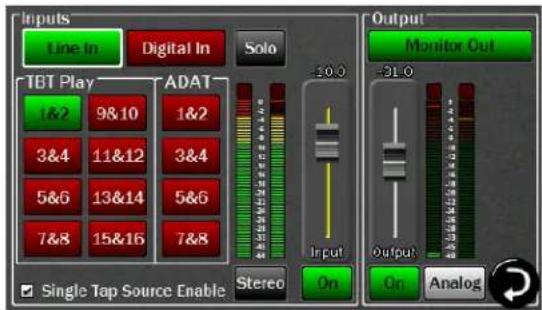
Let's start by setting levels for the recording engineer. Start by selecting "Monitor Out" as the active Output:
We already have signal from Play 1&2 carrying the streams from the computer. Now let's add Line In as a source so there is the new keyboard parts along with the existing tracks.
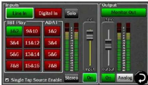
The keyboard level is a bit hot compared to the mix. Let's attenuate the Line In signal by 10dB.
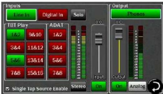
Now let's pull up the Phones Out to adjust the performer's levels. Again, Play 1&2 is pre-assigned as a source.
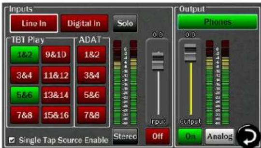
Now we'll add Line In, so the performer can hear their input signal
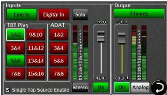
This performer likes the levels of the backing tracks louder, but the overall level down a bit, so we'll nudge the Play source signal up by 6dB, and attenuate the Phones output by 10dB
Now the performer and engineer each have their own monitor mix. Now we're ready to record, keeping in mind that the signals from the Line In will appear in the DAW software as Record 1&2.
As you can see, using variations on the sequence described above, that one can easily integrate outboard processors, and other sound sources into a recording session and maintain complete control over who hears what, and how loud each element will be.
4.5 Tools Page
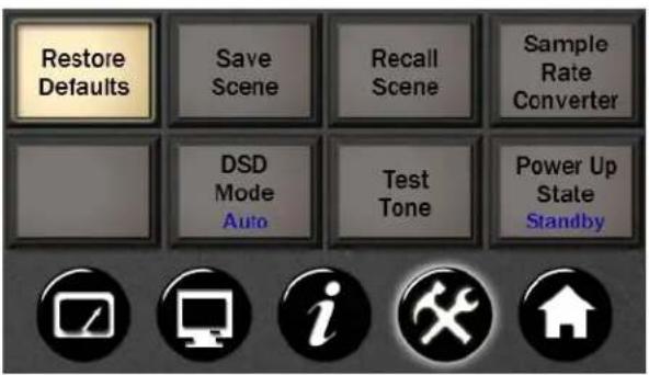
4.5.1 Restore Default Routing
This button restores the factory default settings. It is quite useful as a troubleshooting tool. Generally, it is recommended to save a scene when a custom configuration has been established (described below), but restore defaults is a very speedy way to know if an errant setting is producing performance problems.
4.5.2 Save Scene Button
Once you have created a specific routing/level set up that you may want to recall, here is where you would store it.
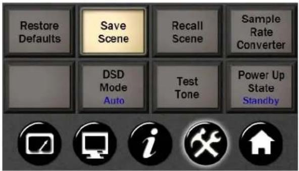
Hilo scenes store routing, clocking settings, level controls, sample rate conversion settings and more into an instantly recall-able "scene". The "Save Scene" button on the Tools page is where this occurs. Now you have the ability to name the scenes.
Once you have a set up that you want to save, press the SAVE SCENE button
![Save Scene As Voiceover Clear 1 2 3 4 5 6 7 8 9 0 - = Back Tab q w e r t y u i o p [ ] \ Cap a s d f g h j k l : ' Enter Shift z x c v b n m , . / Shift Cancel Save](/content/2026/05/773060/images/3b764b69c74eabfa8db40c030a18694ede47fbd156dc3ba5a1cbbf405d28a110.jpg)
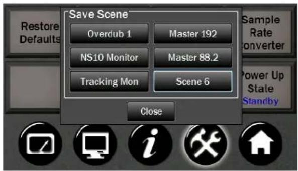
Scene 1 to 6 for storage.
The QWERTY keyboard screen will come up and you can name the scene using up to 13 characters Input the Scene name using your fingers (or some pointed, non-abrasive pointer such as pencil eraser, pen end or even a chop stick). To clear the entire name, tap the Clear button. To backspace and clear one letter at a time, tap the Back button. Tapping the Cap button will capitalize the letters but keep the row of numbers. Tapping Shift capitalizes the letters and changes the numbers to commonly used symbols. Tap the Save button when finished.
You have now stored your scene name, routing, level, meter, sample rate, sync source, trim, digital source, audio settings, UI options and optical mode information.
If you do not want to Save a scene, push the Cancel button at the bottom of the Pop up.
4.5.3 Recall Scene
This button lets you recall the Scenes that you have stored using the Save Scene button.
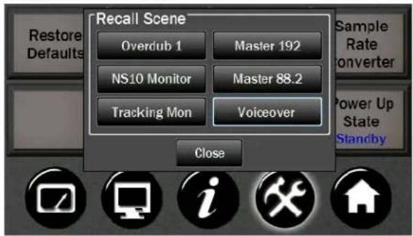
- Push Recall Scene.
- Up to 6 Scenes will be selectable on the Pop up
- Select the Scene you wish to reload.
- The Scene will be instantly loaded with routing, level, meter, sample rate, sync source, trim, digital source and optical mode information.
- If you do not want to Recall a scene, push the Close button at the bottom of the Pop up.
Note: If you Recall a Scene that is empty (not a previously stored Scene), this will restore the default settings.
4.5.4 Sample Rate Converter

Hilo features a powerful Sample Rate Converter for the AES and SPDIF Inputs. When active, the onboard SRC processor supports for conversion ratios up to 16:1 with 144 dB dynamic range and -140dB THD+N. The SRC will convert signals on the active Digital Input up or down to the current Sample Rate.
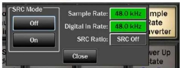
When the Sample Rate Converter button is tapped, SRC can be switched on or off, and information about the current sample rate, digital in rate, and the ratio of conversion, will be displayed if applicable.
Note: Even if the Current Rate and Digital In Rate are the same, sometimes it is useful to have SRC engaged so that the signal streaming to the digital input can be re-clocked. This is a useful state for digital devices that do not have the option to be a clock slave.
The SRC Mode is ON by default. When devices are connected to the Hilo digital inputs and valid clock synchronization is established between them, then it is recommended to turn SRC OFF to insure the best audio performance.
4.5.5 DSD Mode
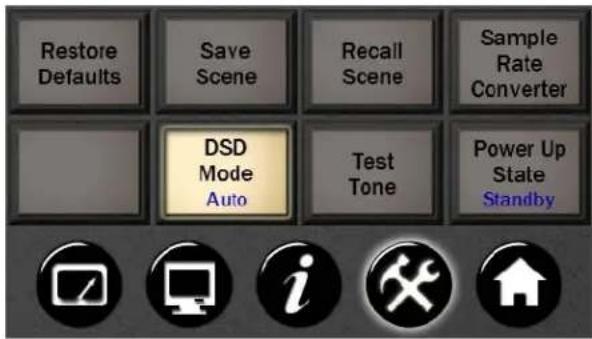
DSD support was added with Hilo Firmware revision 5.
This allows Hilo to play DSD audio files received via Thunderbolt, AES-3 or S/PDIF. Hilo supports the recently adopted DoP V1.1 standard which is a method for transferring DSD audio over PCM frames. Playback of DSD using this method is provided by a growing number of software vendors including Channel D and Audirvana for Macintosh, and JRiver Media Player for Windows.
Using the DSD application of your choice, connect your computer using the TBT or Digital Input (AES IN; S/PDIF COAX IN or S/PDIF OPT IN). Before playing, make sure the DSD Mode button is set to Auto. In this mode DSD
audio in DoP V1.1 is automatically detected on either Hilo TBT input 1 & 2 or the selected Digital In Source. If DSD is detected on both of these sources, priority is given to TBT input 1 & 2.
NOTE: When the DSD Mode is set to Off, incoming data will be processed as standard linear PCM data always. If DSD audio is received in this mode, low volume noise will be played.
DSD Routing: Upon detection of incoming DSD audio, the signal is automatically routed to the Line Outputs, Monitor Outputs, and Headphone Output. Routing to the remaining outputs of Hilo is not affected.

While DSD is playing, any page that has level meters will show a DSD logo instead of the meters. As soon as DSD playback is stopped, the level meter page will return.
4.5.6 Test Tone Function
Intended for system testing and calibration, Hilo's Test Tone provides a 1 kHz audio signal which can be sent to any output or combination of outputs. The tone level can be controlled in 0.5 dB increments from a new dedicated screen. For reference, the same screen also shows the input levels coming into Hilo.
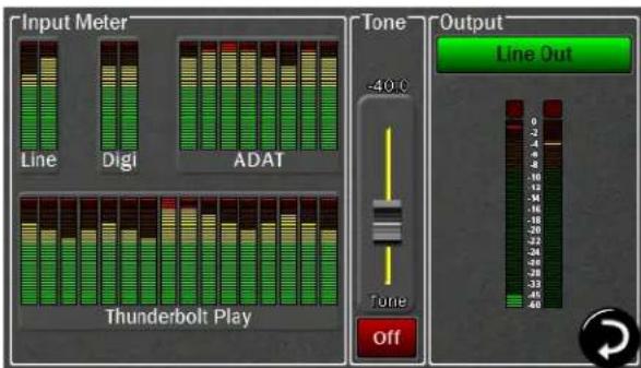
Using the menu button on the Output side (here selected as Line Out), choose the output to which you want to send the test tone.
Use the On/Off button to engage/disengage the test tone.
The initial level is set at -40 dBu. The fader and front panel rotary control allow you to adjust the level in 0.5 dB increments.
Multiple outputs can receive the test tone simultaneously.
Inputs Meters are shown to allow monitoring of any signal being received by the Hilo.
4.5.7 Power Up State
Hilo can be set to toggle between two power up states:

Standby: In this mode, when AC power is applied and the back panel power switch is in the ON position (show graphic), Hilo will be in Standby mode until the front panel STANDBY switch is pressed. Then the Hilo will power up and be ready for use.
On: In this mode, when AC power is applied and the back panel power switch is in the ON position, Hilo will power up and be ready for use. This is a typical setting when Hilo is placed in an equipment rack with a single master power switch for all of the equipment in the rack.
4.6 Information Page
As with the Tools page, there are several open buttons for future features.
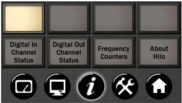
Another advantage of the Touch Screen is that status information can be quickly accessed. This information tells you what is going on “under the hood” of Hilo and provides crucial data for trouble shooting in the field.
All Information pages will stay open until you tap "Close", or the Meter screen comes up based on the "Return to Meters" delay time established in the DISPLAY CONTROLS page.
4.6.1 Digital In Channel Status
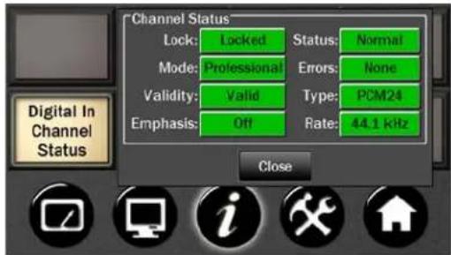
This section displays status information pertaining to the Hilo's digital inputs. The data displayed indicates the quality of the AES/EBU connections as well as channels status data sent by a transmitting device. The information displayed in this section is very useful for troubleshooting digital input connection issues. For more information about AES/EBU channel status data, refer to the AES-3 specification available from the Audio Engineering Society web site at http://www.aes.org
Lock
- Locked (green) Indicates the digital receiver is locked to a valid digital signal.
- Unlocked (gray) Indicates the digital receiver is not locked to a valid digital signal.
Validity
- Valid (green) Indicates the Valid channel status bit is set
- Invalid (red) Indicates the Valid channel status bit is not set
Emphasis
• Off (gray) Emphasis is off
• 50/15us (green) 50/15us pre-emphasis
• J17 (green) CCITTJ.17 emphasis
• Unknown (green) Emphasis not indicated
Rate.
Clock Rate displays a real-time measurement of the sample rates of the incoming signals. These measurements are very useful for evaluating and validating digital inputs when synchronization or clocking issues are encountered.
32.0; 44.1; 48.0; 88.2; 96.0; 176.4; 192.0 kHz (all in green) or Unknown (red)
Note: it is the responsibility of the transmitting device to send rate status that matches the actual rate of the audio data stream being sent. However, it is possible for a rate discrepancy to exist during a valid transmission.
4.6.2 Digital Out Channel Status Button
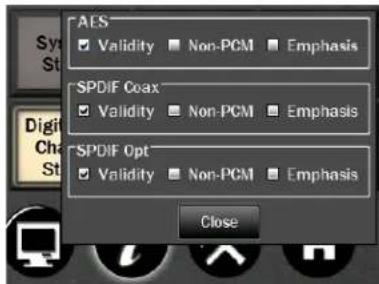
Several selections can be made from this page, as well as showing the current status of the Digital Outputs.
This section provides control of status bits embedded in the AES/EBU stream for each digital output. For more information about the use of these bits, refer to the AES-3 specification available from the Audio Engineering Society web site at http://www.acs.org.
For each of the three possible Digital Outputs (AES, SPDIF Coax, SPDIF Opt you can select one or more:
- Validity This checkbox controls the state of the Valid bit. When checked, the Valid bit is turned on to indicate to the receiving device that the audio data being transmitted is valid. This is the default state.
- Non-PCM This checkbox controls the state of the Non-PCM channel status bit. When checked, the Non-PCM bit is turned on to indicate that audio data other than linear PCM (such as Dolby AC3 or DTS) is being transmitted.
- Emphasis This checkbox controls the state of the emphasis channel status bits. When checked, the 50/15us emphasis mode is indicated in the transmitted channel status.
4.6.3 Frequency Counters
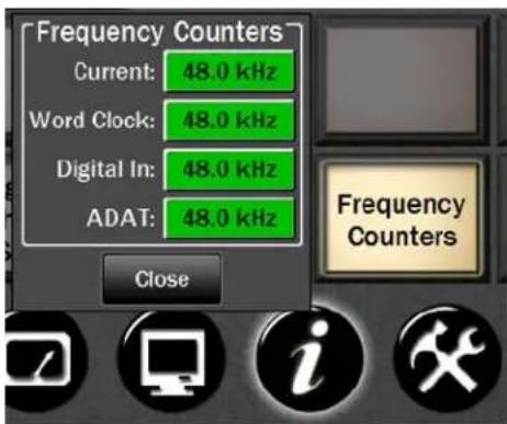
Also a Status button with no selections available. Measured settings will be shown on a Green button. If no signal is detected on an input, the button will be Gray and state "Not Present".
4.6.4 About Hilo
Also a status only button. This screen provides you with the hardware information for Hilo and the LT-TB card, including date of manufacture, hardware and software revision dates.
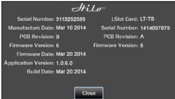
4.7 Display Controls
These controls allow you to customize how you want the LCD screen to work and what information you want it to show.
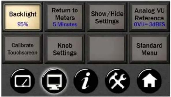
4.7.1 Backlight
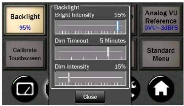
The Backlight button allows the user to adjust Hilo's appearance by using the onscreen faders or Rotary control. You can now:
- Adjust Hilo's brightness intensity in a range of 5% to 100% in 1% increments - ideal for adapting to a variety of ambient light conditions.
- Enable and adjust the new Screen Dim function. Auto-Dim can be activated between 15 seconds to 5 minutes, or set to Never.
The Dim Intensity determines the brightness level when Dim is active. It can be set for as low as 0% (screen off) up to the default state of full brightness
If the screen goes completely dark, Hilo will return to the established Brightness Intensity by touching the screen, moving or pressing the Rotary Control or pressing the front panel Power Switch.
4.7.2 Return to Meters
Hilo will revert to the Meters screen after some period of inactivity. The default period is 15 seconds. This is where you can change that delay time.
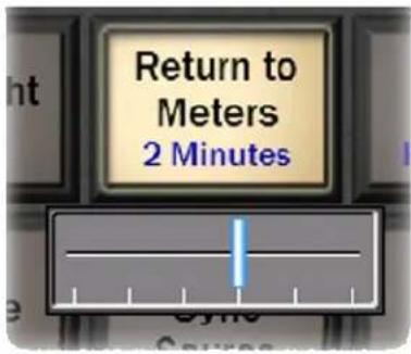
• Shows the current Menu Delay
- This sets the time that any menu, selection page, pop up menu or status page will stay active before the screen defaults back to the selected Meter page. The only menu page that does not "time out" is the Output Mix Routing Page.
- Pushing the button engages a horizontal fader that lets you set the delay to 15 seconds, 30 seconds, 1 minute, 2 minutes, 5 minutes, or Never.
- You may use your finger on the fader to set the delay time
- You may also use the Rotary Control to set the delay time
4.7.3 Show/ Hide Settings
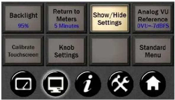
This is a Toggle type button. This button allows you to add Sample Rate, Sync Source or Recall Scene to the VU or Horizontal Meters pages
- Any or all of three choices can be selected by tapping the check box next to each option.
- After selecting the desired choices, tap "Close".
- The selected options will appear at the top of the Horizontal and Analog Meter pages.
4.7.4 Analog VU Reference
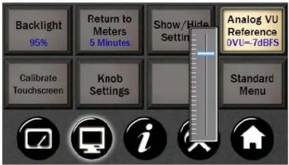
You can calibrate the Analog meters to set the 0 VU level.
Using the fader on-screen or the Rotary Knob, the 0 VU mark on the meters can be calibrated between -3dBFS and -24dBFS
4.7.5 Calibrate Touchscreen
The LCD Touchscreen has a grid that detects when you touch it to select or change settings. If you find that the touch response gets slow or does not always engage properly, you may need to recalibrate the touch screen.
- Push the Calibrate Touchscreen button.
- The screen will go black and give you instructions for recalibrating the screen.
Simply follow the instructions and the previous screen will come up when done. Be sure to touch directly in the center of the target to give the most accurate touchscreen calibration.
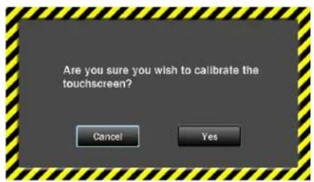
With a touch screen it is easy to engage the wrong function by mistake. This screen allows you to back out of this command if you wish.
There are times when calibrating the touchscreen is necessary for optimum performance. However if this setting was selected unintentionally, now you can overrule the request and return to the Display Menu page.
4.7.6 Knob Settings
This menu allows you to select which outputs can be adjusted with the Hilo rotary encoder. By default, the Monitor Out and the Phones Out can be attenuated with the rotary encoder, and pressing in the knob will toggle between those two choices. If additional choices are selected from the Knob Settings menu, then pressing in the Rotary Encoder will toggle through all the Outputs that have been selected.
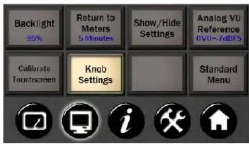
- Monitor Out and Phones Out can be de-selected by clicking in the adjoining checkboxes, and/or additional outputs can be selected with their adjoining check boxes.
- Up to three sources can be selected at one time
- After the desired sources have been selected, turning the rotary encoder from any Hilo screen other than the Outputs Mix Routing page will change volume for the selected output and a level meter will show onscreen.
- Pressing in the Rotary Encoder Knob will toggle through the available choices.
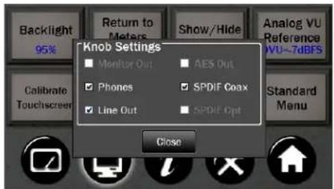
4.7.7 Standard Menu
Some Hilo users prefer a simpler interface with only the essential controls being available. The Standard Menu button toggles between Standard Mode (simplified interface) and Advanced Mode (complete interface). The default is Advanced Mode. When Standard Menu is selected, the Hilo interface is reduced to 6 buttons and the METER selection icon.
As soon as Standard Menu is selected, the Hilo does a Restore Defaults to return all routing and volume controls to the default setting. This may result in the audio from a previously muted or attenuated source to come through the Hilo at full volume.
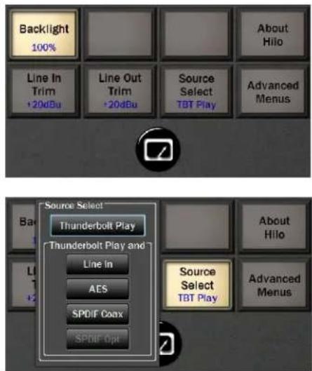
- The Backlight button allows control of the Hilo touchscreen appearance. See Section 4.7.1
- The About Hilo page is a status only button. This screen provides you with the hardware information for Hilo and the LT-TB card, including date of manufacture, hardware and software revision dates.
- The Line In and Line Out Trim buttons set the calibration level for the Hilo Line Inputs and Line Outputs. See Section 4.4.5 and Section 4.4.6 for more information.
- The Select Source button determines which signal source, will be streamed to ALL of the Hilo outputs. Choose between TBT Play (play streams from the computer via the Thunderbolt connection) or any of the other Audio inputs on the Hilo. Note: ADAT Lightpipe I/O is not available in Standard Mode.
- The Advanced Menus button returns the Hilo touchscreen to Advanced Mode.
- The METERS icon will return the screen to the Hilo METER display. The three METER options are still available from the METERs page.
If any Hilo parameters that only appear in Advanced mode have been altered, and then the Hilo was switched to Standard Mode, the alterations will no longer be active. For instance, if the RETURN TO METERS selection was set to "15 seconds" in Advanced Mode, when switched to Standard Mode the default state of "5 minutes" will be active. When returning to Advanced Mode, the default will continue to be active and an alteration will have to be manually selected.
4.8 Meter Button

This button simply sends you back to the last Meter page that you selected.

5 Support
We are devoted to making your experience with Hilo trouble-free and productive. If the troubleshooting and operational sections of this manual did not help resolve your questions, several support options are available to you:
5.1 Lynx Website Support Resources
Logging on to http://www.lynxstudio.com > Support, will provide several options for resolving your support issues:
Downloads
A library of current firmware and driver files are available for download and installation. Check back regularly to insure that your Hilo is up-to-date.
Contact Tech Support
For direct attention from the Lynx Technical Support Staff, registered users can submit a support ticket online that details their problem and steps they've taken to resolve it. Most Support Ticket submissions are responded to within 24 hours.
Frequently Asked Questions
An extensive catalog of FAQs derived directly from our most common tech support inquiries. Our FAQ section is updated regularly and designed to allow users to find the answers to their most common questions quickly.
Lynx Support Forum
An online Lynx users support forum provides a venue for customers to post questions and issues and receive responses from other users as well as Lynx technical administrators. Searching previous posts is often an excellent way to uncover valuable information about Hilo operation and troubleshooting.
See http://www.lynxstudio.com/forum
Support Documents and User Manuals
A library of useful “how-to” documents, troubleshooting aids and charts are available for 24/7 assistance.
User Manuals are also conveniently available online for all Lynx products
Facebook Support Information Group
Like us? Then Like us on Facebook to be alerted to the latest support, product and product information.
5.2 Telephone Support
Telephone support is available by calling +1 (714) 545-4700 extension 206 from 9AM to 5PM Pacific Time, Monday through Friday, excluding United States Holidays.
5.3 Registering your Hilo
Lynx is committed to providing you with the best service possible. To help us serve you better, please be sure to register your Hilo. Register on the web at: http://www.lynxstudio.com/register.html Once you are registered you will automatically receive notifications of new products and upgrades.
5.4 Return Policy
If you have a unit that you suspect is defective or is malfunctioning contact Lynx technical support via one of the means described above for diagnosis. If the technician determines that the unit is faulty, they will issue an RMA number so you can send the unit in for repair. Units received without a valid RMA number will be refused. All RMA numbers are valid for 30 days from the date of issue.
6 Appendices
6.1 Battery Information
Hilo can operate off of a portable DC Battery Pack for field recording or whenever AC power is not available. The BATTERY IN connector is located directly above the AC connector on the Hilo back panel.
Battery Packs can be purchased from retailers of video cameras and other electronics equipment. Almost any lead acid or lithium battery should work as long as it has the following characteristics:
• 9-18 Volts. Typical choices are either 12V or 14V.
- A 4-pin XLR connector. The connection should have pin 4 hot, and pin 1 for ground. No other pins are connected. This is a standard configuration.
- Hilo consumes 22 Watts. Check with the battery's stated watt hours to determine operating time you can expect with a fully charged battery. For instance, a 60 watt-hour battery would provide up to 2.72 hours of operation.
6.2 Setting Trim Pots
As discussed in sections 3.4.5 and 3.4.6, Hilo's Line Inputs and Line Outputs can be set to Trim values of +18 dBu; +20 dBu; +22 dBu; +24 dBu; +0 dBV; +2 dBV; +4 dBV and +6 dBV. These trim positions are factory calibrated to these values within 1/100th of a dB. Trim levels can be selected from the Hilo Home Page. These set levels will satisfy the overwhelming majority of Hilo users.
In some cases, these levels may need to be tweaked to match the reference level of gear that is not calibrated as accurately. Also, in time and due to changes in temperature, it may be necessary to tweak trim levels to set them back to their original reference.
For this purpose, Hilo has ultra accurate, 25-turn trim pots accessible from the bottom of the chassis that can be used to adjust + or - .5dB from the established trim level. Here are the steps to calibrate via these trim pots:
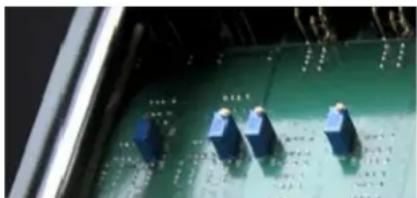
natural_image
Close-up of electronic circuit board components with blue connectors (no visible text or symbols)- Remove the plate from the bottom of Hilo. There are four screws that hold it in place. The front-right rubber foot will need to be removed to allow access to one of the screws. Locate the input and output trim pots on the underside of the Hilo main board.
-
Set the Line In and/or Line Out trim levels on the Hilo Home page to the value closest to your desired level.
-
It is best to use sine wave tones to adjust trims. If adjusting Input trim levels, send tones from an external device and measure the results in either software or a scope with digital inputs. It is best to avoid analog input routed to analog output paths for this kind of calibration. If adjusting Hilo Output Trims, send tones from a software source via the USB connection, or tones from an external device connected to one of Hilo's digital inputs routed to the Line Out. Make sure that the entire signal path is set to unity gain.
-
Adjust the trims clockwise to increase the gain on the inputs or outputs, or counter clockwise to decrease gain until the desired reference level is achieved.
Keep in mind that this variation will also be represented in other trim levels that are selected. For instance if a trim level of +22dB is active, and the trim pots have altered that to 22.25dB, if later a trim value of +24dB is selected from the Hilo, the resulting signal will be +24.25 dB.
6.3 XLR Connector Wiring and Adapters
This section describes the proper wiring of cables that can be used to adapt both the Analog and AES Digital XLR connectors on the Hilo.
6.3.1 Balanced Connections
The wiring method for balanced connections with XLR connectors to balanced TRS ( 14 " phone) connectors using shielded twisted pair cable (2 wire + shield) is as follows:
XLR Pin 1 (GND) to cable shield and to the TRS sleeve
XLR Pin 2 (+) to one signal wire and to the TRS tip
XLR Pin 3 (-) to the other signal wire and to the TRS ring
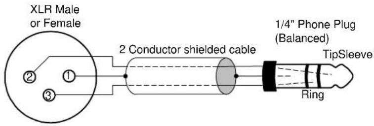
6.3.2 Unbalanced Connections with Twisted Pair Cable
The wiring method for unbalanced connections with XLR connectors to 14 " phone connectors (tip and sleeve only) using shielded twisted pair cable (2 wire + shield) is as follows:
XLR Pin 1 (GND) to cable shield with no connection on the other end
XLR Pin 2 (+) to signal wire and to the 14 " phone tip
XLR Pin 3 (-) to the other signal wire and to the 14 " phone sleeve
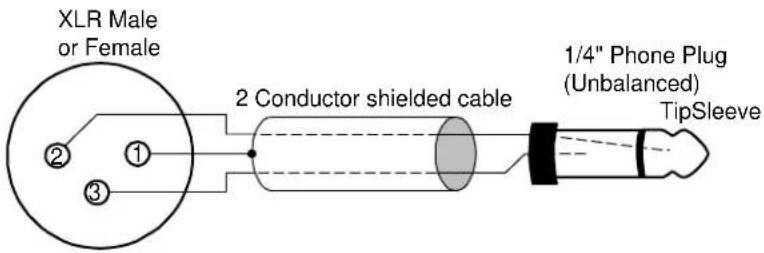
The wiring method for unbalanced connections with XLR connectors to RCA/Phono phone connectors using shielded twisted pair cable (2 wire + shield) is as follows:
XLR Pin 1 (GND) to cable shield with no connection on the other end
XLR Pin 2 (+) to signal wire and to the Phono center pin
XLR Pin 3 (-) to the other signal wire and to the Phono sleeve
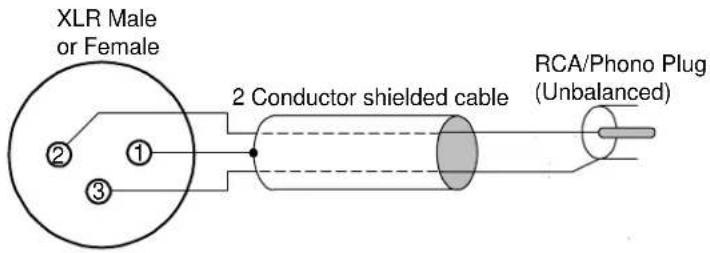
6.3.3 Unbalanced Connections with Single Conductor Cable
In some cases it may be necessary to use single-conductor cable to adapt to unbalanced devices. These cables are considerably more susceptible to interference and grounding problems than the two conductor cables shown above. Two-conductor cables should be used whenever possible.
The wiring method for unbalanced connections with XLR connectors to unbalanced 14 " phone connectors (tip and sleeve only) using coaxial cable (1 wire + shield) is as follows:
XLR Pin 1 (GND) no connection
XLR Pin 2 (+) to signal wire and to the 14 " phone tip
XLR Pin 3 (-) to the cable shield and to the 14 " phone sleeve
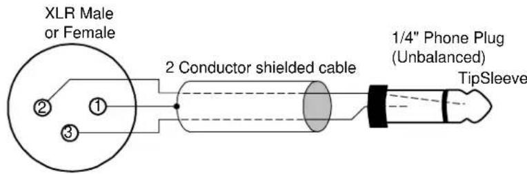
The wiring method for unbalanced connections with XLR connectors to unbalanced RCA/Phono phone connectors using coaxial cable (1 wire + shield) is as follows:
XLR Pin 1 (GND) no connection
XLR Pin 2 (+) to signal wire and to the Phono center pin
XLR Pin 3 (-) to the cable shield and to the Phono sleeve
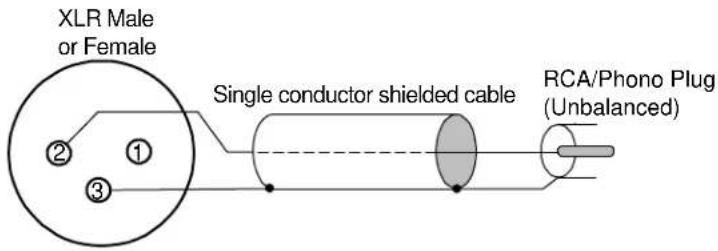
6.4 Setting the Monitor Out Level Mode
By default, the Hilo Monitor Outputs are calibrated to a maximum of +10dBu. This is a standard reference level for powered monitors. If the Monitor Outputs are to be used with powered monitors or a power amp connected to passive monitors, then this setting is likely appropriate.
If instead, one wishes to connect the Monitor Output to some other professional line level device, then it may be desirable to set the Monitor Out to its alternate setting, which is +24dBu.
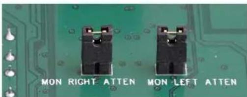
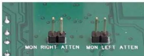
Monitor Output Level Default +10 dBu Monitor Output Level Option +24 dBu
This setting is established with jumpers on the Hilo mainboard. To access them, remove the bottom plate on the Hilo (it will be necessary to remove one of the rubber feet to accomplish that). The pins in question are labeled Mon Right Atten (short for Monitor Output Right Channel Attenuation) or Mon Left Atten. Removing the jumpers sets the levels to the alternate +24dBu mode.
If the desired level is less than +24dBu (+22dBu) for instance, then you can additionally attenuate with the Hilo Monitor Out volume control.
7 Troubleshooting & User Tips
Q. After driver installation, the Hilo does not appear to the OS as an active device
A. Check the following:
* Make sure that the Operating system is compatible with Hilo/TB
* If used with a Windows computer, make sure that the Thunderbolt chipset drivers for the motherboard have been installed. See the manufacturer's support resources for details
* Verify that the Hilo has firmware revision 6 or above (from ABOUT HILO on the Information page)
* Make sure that the Thunderbolt cables are seated correctly on both ends
* Try the other Thunderbolt port on the Hilo, as well as a different Thunderbolt port on the computer if applicable
Q. When I change my Sync Source or Sample Rate on the Hilo, I get distortion on the outputs.
A. Make sure that any audio applications are closed when changing Sync Source or Sample Rate. Insure that the Sample Rate in the audio software matches the Sample Rate of the Hilo.
Q. What does the white box around the Input Source mean?
A. That means that that Input is in “Focus”. In other words, the Input Level Fader, Metering and ON/OFF state are for that selected (Focused) input. This is useful since you may have multiple Inputs feeding an Output and may want to check levels, etc. for one of them.
Q. I have multiple sources coming into Hilo and they are all mixing onto the same tracks in my DAW.
A. In the OUTPUT MIX ROUTING PAGE, select the Output (e.g. TBT REC 1 &2) and make sure you do not have any unwanted Inputs being routed to that Output. To turn off an Input, tap the ON button so it becomes a red OFF or you can tap the Input (once if it is already in “Focus” or twice if it is not) until it turns red.
Q. My monitor level (or phones) is turned up but the audio is still very low.
A. Check the Input Level for the Inputs feeding that Output and make sure they are at a sufficient level. Also, for MONITOR OUT and PHONES, tap the “Analog” button (at the bottom of the Outputs field) to switch it to the Digital Level, and make sure that level was not turned down.
Q. My output level is turned down but the audio is distorted.
A. Check your Input Levels to your selected Output. The Input Source Level has the ability to be raised higher than “0” level and thus can add gain that may distort your output.
Q. I am mixing Inputs to my Monitors (or Phones) and the Output is distorting. I like the mix of the Inputs and I do not want to have to turn down each Input one at a time. What can I do?
A. Tap the “Analog” button (at the bottom of the Outputs field) to switch it to the Digital Level. This is the digital output level before it feeds the analog MONITOR and PHONES. Bring the Digital Level down until you are not hitting the “Overs” on the Output Meters.
Q. When do I use the Sample Rate Converter?
A. There are two situations where you would the SRC:
1) When your digital inputs to Hilo are coming in at a sample rate that differs from the sample rate of Hilo. Hilo will up-or-down sample the input signal to match itself and
2) If your digital sources are coming in at the same sample rate as Hilo, but your digital sources have no ability to clock slave to Hilo (e.g. consumer CD players). The SRC will re-clock the digital input signal to make sure it is in Sync with Hilo's clock.
Q. I am using a mono input into the Line In of Hilo. I have the Line In assigned to my Monitors and Phones Output but I am only hearing it one side (the side it is connected to). Why?
A. To monitor a mono input signal in the center of the stereo field, go to the Output Mix Routing Page and select the Input you would like to monitor (make sure the white box is around the Input so that it is "focused" or selected). Under the Input Meters is the MONITOR MODE select button. Tap that button to launch the menu of options. If your signal source is plugged into the Left Input of the selected source, then select "Left". If it is plugged into the Right Input, Select "Right". On the OUTPUT METERS you should now see your signal on the both the left and right sides. Note: The MONITOR MODE selection is active PER INPUT and PER OUTPUT. While this makes the feature very flexible, keep in mind you may need to select the correct mode for multiple outputs (such as MONITOR OUT and PHONES).
8 Specifications
Line In L/R
THD+N -114 dB @1kHz, -1dBFS, 20kHz filter, +22dBu trim
Dynamic Range 121 dB, A-weighted, -60dBFS signal method
Frequency Response ± 0.01 dB, 20 – 20kHz
Crosstalk 140 dB maximum @ 1kHz, -1dBFS signal
Full-scale trim settings + 0dBV, +2dBV, +4dBV, +6dBV, +18dBu, +20dBu, +22dBu, +24dBu
Input Impedance 200k Ohms balanced, 100k Ohms unbalanced
Female XLR connectors
Line Out L/R
THD+N -109 dB @1kHz, -1dBFS, 20kHz filter, +22dbu trim
Dynamic Range 121 dB, A-weighted, -60dBFS signal method
Frequency Response ± 0.02 dB, 20 – 20kHz
Crosstalk -135 dB maximum @ 1kHz, -1dBFS signal
Full-scale trim settings + 0dBV, +2dBV, +4dBV, +6dBV, +18dBu, +20dBu, +22dBu, +24dBu
Output Impedance 100 Ohms balanced, 50 Ohms unbalanced
Male XLR connectors
Monitor Out L/R
THD+N -107 dB @1kHz, -1dBFS, 20kHz filter, volume at max
Dynamic Range 121 dB, A-weighted, -60dBFS signal method
Frequency Response ± 0.02 dB, 20 – 20kHz
Crosstalk -135 dB maximum @ 1kHz, -1dBFS signal
Output level at max volume +24dBu or +10dBu, jumper selectable TRS connectors
Headphone Out
THD+N -107 dB @1kHz, -1dBFS, 20kHz filter, volume at max
Dynamic Range 121 dB, A-weighted, -60dBFS signal method
Frequency Response ± 0.02 dB, 20 – 20kHz
Crosstalk -130 dB maximum @ 1kHz, -1dBFS signal
Output level at max volume +19dBu
14 phone jack on front panel
Digital I/O
AES/EBU Transformer-coupled on XLR connectors
S/PDIF I/O coax
Transformer-coupled on RCA jacks
S/PDIF I/O optical On optical connectors
ADAT I/O 8 channels at 48 kHz when selected on optical connectors
Sample Rates
All standard rates up to 192 kHz using SynchcroLock sample clock generator
Synchronization Options
Internal
External word clock I/O 75ohm TTL signal on BNC connectors
AES/EBU or S/PDIF inputs XLR, RCA or Toslink connectors
Computer Connectivity
Windows 7 and Windows 8, 32-bit and 64-bit drivers provided by Lynx
Macintosh OS X 10.8.5 or higher, drivers provided by Lynx
LSlot™ Expansion Port
Supports Lynx LSlot expansion cards with up to 32 input and outputs simultaneously
LCD Display
480 x 282 LCD Touch Screen
AC Power 110 to 230 VAC, 30 watts;
Battery Power 9-18 volts DC on 4-pin XLR
Size 8.50" wide x 3.25" tall x 10.00" deep
Shipping Weight 12 pounds
Certifications
CE and FCC Class B EMI, CE Product Safety
9 Certifications
9.1 FCC DECLARATION OF CONFORMITY
MANUFACTURERS NAME: Lynx Studio Technology, Inc.
MANUFACTURER ADDRESS: 190 McCormick Avenue
Costa Mesa, CA 92626, U.S.A.
TELEPHONE
(714)
545-4700
COMPLIANCE TEST REPORT NUMBER: D11123R1
COMPLIANCE TEST REPORT DATE: January 12, 2012
TYPE OF EQUIPMENT: Professional A/D and D/A Converter
EQUIPMENT CLASS:
Residential, Commercial, Light Industry, Urban Outdoors, Dedicated Studios
MODEL NUMBER: Hilo
CONFORMS TO THESE SPECIFICATIONS: CFR Title 47 FCC Part 15 Subpart B Class B per CISPR 22 Limits
TEST PROCEDURE: ANSI C63.4
YEAR OF MANUFACTURE: 2011

This equipment has been tested and found to comply with the limits for a Class B digital device, pursuant to Part 15 of the FCC rules. These limits are designed to provide reasonable protection against harmful interference in a residential installation. This equipment generates, uses, and can radiate radio frequency energy and, if not installed and used in accordance with the instructions, may cause harmful interference to radio communications. However, there is no guarantee that interference will not occur in a particular installation.
If the unit does cause harmful interference to radio or television reception, please refer to your user's manual for instructions on correcting the problem.
I the undersigned, hereby declare that the equipment specified above conforms to the above requirements.
Costa Mesa, California
January 12, 2012
Robert J. Bauman
Compliance Engineer
9.2 CE EMC DECLARATION OF CONFORMITY
MANUFACTURERS NAME: Lynx Studio Technology, Inc.
MANUFACTURER ADDRESS: 190 McCormick Avenue
Costa Mesa, CA 92626, U.S.A.
TELEPHONE (714) 545-4700
COMPLIANCE TEST REPORT NUMBER: D20110Q1
COMPLIANCE TEST REPORT DATE: January 12, 2012
TYPE OF EQUIPMENT: Professional A/D and D/A Converter
EQUIPMENT CLASS: Residential, Commercial, Light Industry, Urban Outdoors, Dedicated Studios
MODEL NUMBER: Hilo
CONFORMS TO THESE SPECIFICATIONS: EN 55103-1:2009 for environment categories E1 – E4 which references the following specifications:
EN 55013:2001, EN 55014:2002, EN 55022:2006,
EN 61000-3-2:2006, EN 61000-3-3:2008
EN 55103-2:2009 for environment categories E1 – E4 which references the following specifications:
EN 61000-4-2:2001, EN 61000-4-3:2008, EN 61000-4-4:2004,
EN 61000-4-5:2006, EN 61000-4-6:2007, EN 61000-4-11:2004
YEAR OF MANUFACTURE: 2011
I the undersigned, hereby declare that the equipment specified above conforms to the above directives and standards.
Costa Mesa, California
January 12, 2012
Robert J. Bauman
Compliance Engineer
9.3 CE SAFETY DECLARATION OF CONFORMITY
MANUFACTURERS NAME: Lynx Studio Technology, Inc.
MANUFACTURER ADDRESS: 190 McCormick Avenue
Costa Mesa, CA 92626, U.S.A.
TELEPHONE (714) 545-4700
COMPLIANCE TEST REPORT NUMBER: D20118S2
COMPLIANCE TEST REPORT DATE: January 23, 2012
TYPE OF EQUIPMENT: Professional A/D and D/A Converter
EQUIPMENT CLASS: Residential, Commercial, Light Industry, Urban Outdoors, Dedicated Studios
MODEL NUMBER: Hilo
CONFORMS TO THESE SPECIFICATIONS: EN 60065:2002 + A1:2006 + A2:2010 + A11:2008 + A12:2011
YEAR OF MANUFACTURE: 2011
I the undersigned, hereby declare that the equipment specified above conforms to the above directives and standards.
Costa Mesa, California
January 23, 2012
Robert J. Bauman
Compliance Engineer
10 Warranty Information
Hilo/TB
One year Free Labor / One year Parts Exchange
This product must be returned to the factory for repair.
Who Is Covered?
You must have proof of purchase to receive warranty service. A sales receipt or other document showing when and where you purchased the product is considered proof of purchase. This warranty is enforceable only by the original retail purchaser. To be protected by this warranty, the purchaser must register online within 14 days of purchase.
What Is Covered?
Warranty coverage beings the day you buy your product. For one year thereafter, Lynx shall, at its sole and absolute option, either repair or replace free of charge any product that proves to be defective on inspection by Lynx or its authorized service representative. In all cases disputes concerning this warranty shall be resolved as prescribed by law. All parts, including repaired and replaced parts, are covered only for the original warranty period. When the warranty on the product expires, the warranty on all replaced and repaired parts also expires.
What Is Excluded?
Your warranty does not cover:
• Labor charges for installation or setup of the product.
- Product repair and/or part replacement because of misuse, accident, unauthorized repair or other cause not within the control of Lynx.
- A product that requires modification or adaptation to enable it to operate in any country other than the country for which it was designed, manufactured, approved and/or authorized, or repair of products damaged by these modifications.
- Incidental or consequential damages result from the product, damage to property, damage based on inconvenience or on loss of use of the product, and, to the extent permitted by law, damages for personal injury. Some states do not allow the exclusion or limitation of incidental or consequential damages, so the above limitation or exclusion may not apply to you.
- A product that is used for rental purposes.
To Get Warranty Service...
To obtain warranty service, the purchaser must first call or email Lynx at the email address or telephone number printed in Section 5 to obtain a Return Authorization Number and instructions concerning where to return the unit for service. All inquiries must be accompanied by a description of the problem. All authorized returns must be sent to Lynx or an authorized Lynx repair facility postage prepaid insured and properly packaged. Proof of purchase must be presented in the form of a bill of sale, canceled check or some other positive proof that the product is within the warranty period. Lynx reserves the right to update any unit returned for repair. Lynx reserves the right to change or improve design of the product at any time without prior notice.
Lynx Studio Technology, Hilo and the Hilo Logo are trademarks of Lynx Studio Technology, Inc. All other product or company names are the trademarks or registered trademarks of their respective owner.
NOTES
Lynx STUDIO
TECHNOLOGY
LYNX STUDIO TECHNOLOGY
www.lynxstudio.com
© 2014 Lynx Studio Technology Inc.
- User Manual
- Table of Contents
- Introduction....1
- Getting Started....5
- Using the Hilo/TB....15
- Controlling Hilo 21
- Introduction
- Overview
- Features
- In the Box
- Power and Safety Information
- Rack-Mounting
- Operation Requirements
- Audio Equipment Requirements
- Computer requirements
- Windows
- Macintosh OS X
- Compatible Firmware
- Using this manual
- Registration
- Getting Started
- Unpacking
- Set up
- Cable Connections
- ① Thunderbolt port
- ② LINE IN
- ③ LINE OUT
- MONITOR OUT
- ⑤ AES IN/OUT
- ⑥ S/PDIF/ ADAT Optical
- ⑦ SPDIF Coaxial In Out
- Wordclock In/Out
- ⑨ Battery In
- ⑩ IEC Power connector
- Initial Setup
- Computer Set Up
- Cable Setup
- Driver Installation
- Windows 7 (32-bit or 64-bit) or Windows 8
- OS X
- Using Multiple Hilos and/or Auroras
- Connect the cables
- Setting Device Order
- Set the Sync Source
- Configure for use
- Using LT-TB with other Thunderbolt Devices
- Bus Powered Devices
- Using the Hilo/TB
- Hilo Driver Devices – Windows Operating Systems
- WDM/Multimedia Applications
- ASIO Application
- Controlling Latency by Changing the Buffer Size
- Hilo Driver Devices - Macintosh OS X
- OSX Audio Applications
- Controlling Latency by Changing the Buffer Size
- Firmware Updates
- Controlling Hilo
- On Power Up
- Headphone and Monitor Out Volume Control
- Changing the Meter Page
- Choosing the Meter Source
- For the Analog VU Meters:
- For the Horizontal Meters:
- For the All I/O Meters
- Getting to the Menu Pages
- Menu Screen conventions:
- Home Menu
- Sample Rate
- Sync Source
- SynchroLock
- Locked
- Working
- Range
- Disabled
- Optical Out Mode
- Line In Trim
- Line Out Trim
- Digital In Source
- Output Mix Routing Page
- Monitoring Modes
- Solo Button
- Input Sources
- Outputs
- Analog and Digital Level Controls for Monitor and Headphones
- Single Tap Source Select
- Selecting Monitor Sources
- Adjusting levels of input sources and outputs
- Routing tutorial
- Tools Page
- Restore Default Routing
- Save Scene Button
- Recall Scene
- Sample Rate Converter
- DSD Mode
- Test Tone Function
- Power Up State
- Information Page
- Digital In Channel Status
- Lock
- Validity
- Emphasis
- Rate.
- Digital Out Channel Status Button
- Frequency Counters
- About Hilo
- Display Controls
- Backlight
- Return to Meters
- Show/ Hide Settings
- Analog VU Reference
- Calibrate Touchscreen
- Knob Settings
- Standard Menu
- Meter Button
- Support
- Lynx Website Support Resources
- Downloads
- Contact Tech Support
- Frequently Asked Questions
- Lynx Support Forum
- Support Documents and User Manuals
- Facebook Support Information Group
- Telephone Support
- Registering your Hilo
- Return Policy
- Appendices
- Battery Information
- Setting Trim Pots
- XLR Connector Wiring and Adapters
- Balanced Connections
- Unbalanced Connections with Twisted Pair Cable
- Unbalanced Connections with Single Conductor Cable
- Setting the Monitor Out Level Mode
- Troubleshooting & User Tips
- Specifications
- Line In L/R
- Line Out L/R
- Monitor Out L/R
- Headphone Out
- Digital I/O
- Sample Rates
- Synchronization Options
- Computer Connectivity
- LSlot™ Expansion Port
- LCD Display
- Certifications
- Certifications
- FCC DECLARATION OF CONFORMITY
- CE EMC DECLARATION OF CONFORMITY
- CE SAFETY DECLARATION OF CONFORMITY
- Warranty Information
- Hilo/TB
- Who Is Covered?
- What Is Covered?
- What Is Excluded?
- To Get Warranty Service...
- Lynx STUDIO
- TECHNOLOGY
Brand : LYNX
Model : Hilo TB
Category : Hi-Fi System