HMIP-BWTH - Thermostat EQ-3 - Free user manual and instructions
Find the device manual for free HMIP-BWTH EQ-3 in PDF.


| Product Type | Wireless Radiator Thermostat |
| Brand | eQ-3 |
| Model | HMIP-BWTH |
| Dimensions (HxWxD) | Approx. 85 x 55 x 75 mm |
| Weight | Approx. 130 g (including batteries) |
| Power Supply | 2 x AA alkaline batteries (included) |
| Communication | Homematic IP wireless protocol (868 MHz) |
| Valve Connection | M30 x 1.5 (adapter for other threads included) |
| Temperature Range | 5 °C to 30 °C (in 0.5 °C steps) |
| Display | LCD with white backlight |
| Functions | Automatic heating control, manual adjustment, boost, holiday mode, window open detection, frost protection |
| Applicable Standard | EN 60730-1, EN 55014, Homematic IP |
| Protection Class | IP20 (indoor use only) |
| Battery Life | Up to 2 years (typical use) |
| Cleaning | Wipe with a dry, soft cloth; do not use solvents |
| Safety Notes | Do not immerse in water; keep away from children; dispose of batteries separately |
| Spare Parts / Repairability | Valve adapters available; can be replaced by user; no user-serviceable parts inside |
| System Requirements | Homematic IP Access Point or Central Control Unit (CCU2/CCU3) |
Frequently Asked Questions - HMIP-BWTH EQ-3
User questions about HMIP-BWTH EQ-3
0 question about this device. Answer the ones you know or ask your own.
Ask a new question about this device
Download the instructions for your Thermostat in PDF format for free! Find your manual HMIP-BWTH - EQ-3 and take your electronic device back in hand. On this page are published all the documents necessary for the use of your device. HMIP-BWTH by EQ-3.
USER MANUAL HMIP-BWTH EQ-3
Wall Thermostat with switching output – for brand switches p. 49

Lieferumfang
Anzahl Bezeichnung
Printed in Hong Kong
3

4

5

6

Inhaltsverzeichnis
1 Homematic IP Wall Thermostat with switching output – for brand switches
1 Clip-on frame
1 Voltage supply unit
2 Screws 3.2 x 15 mm
2 Screws 3.2 x 25 mm
1 Operating manual
Documentation © 2017 eQ-3 AG, Germany
All rights reserved. Translation from the original version in German. This manual may not be reproduced in any format, either in whole or in part, nor may it be duplicated or edited by electronic, mechanical or chemical means, without the written consent of the publisher.
Typographical and printing errors cannot be excluded. However, the information contained in this manual is reviewed on a regular basis and any necessary corrections will be implemented in the next edition. We accept no liability for technical or typographical errors or the consequences thereof.
All trademarks and industrial property rights are acknowledged.
Printed in Hong Kong
Changes may be made without prior notice as a result of technical advances.
150633 (web)
Version 1.0 (02/2017)
Table of contents
1 Information about this manual.... 44
2 Hazard information....44
3 Function and device overview 47
4 General system information 49
5 Start-up 50
5.1 Installation instructions 50
5.2 Installation.... 52
5.3 Behaviour after switching on the mains voltage ..... 53
5.4 Teaching-in 54
5.4.1 Pairing with a Homematic IP Floor
Heating Actuator....54
5.4.2 Teaching-in to the Homematic IP Access Point....55
6 Operating modes and configuration ....57
6.1 Automatic mode....58
6.2 Manual operation....59
6.3 Holiday mode....59
6.4 Operating lock....60
6.5 Valve type and domestic heating system 61
6.6 Programming the week profiles....62
6.6.1 Heating or cooling....63
6.6.2 Week profile number 63
6.6.3 Week profile 67
6.6.4 Optimum start/stop function 68
6.7 Date and time....68
6.8 Offset temperature....68
6.9 Selecting the desired temperature display....69
6.10 Configuring the floor heating actuator....69
6.11 Communication test....70
7 Operation....71
8 Troubleshooting 72
8.1 Command not confirmed....72
8.2 Duty cycle 72
8.3 Error codes and flashing sequences ....73
9 Restore factory settings....75
10 Maintenance and cleaning 76
11 General information about radio operation....77
12 Technical specifications....78
1 Information about this manual
Please read this manual carefully before beginning operation with your Homematic IP components. Keep the manual so you can refer to it at a later date if you need to. If you hand over the device to other persons for use, please hand over this manual as well.
Symbols used:

Attention!
This indicates a hazard.

Please note:
This section contains important additional information.
2 Hazard information

Do not open the device. It does not contain any parts that can be maintained by the user. In the event of an error, please have the device checked by an expert.

For safety and licensing reasons (CE), unauthorized change and/or modification of the device is not permitted.

The device may only be operated in dry and dust-free environment and must be protected from the effects of moisture, vibrations, solar or other methods of heat radiation, cold and mechanical loads.

The device is not a toy; do not allow children to play with it. Do not leave packaging material lying around. Plastic films/bags, pieces of polystyrene, etc. can be dangerous in the hands of a child.

We do not assume any liability for damage to property or personal injury caused by improper use or the failure to observe the hazard information. In such cases, any claim under warranty is extinguished! For consequential damages, we assume no liability!

The device may only be used for fixed installations. The device must be securely attached within a fixed installation.

The actuator is part of the building installation. The relevant national standards and directives must be taken into consideration during planning and set-up. The device has been designed solely for operation on a 230 V/50 Hz AC supply. Only qualified electricians (to VDE 0100) are permitted
to carry out work on the 230 V mains. Applicable accident prevention regulations must be complied with whilst such work is being carried out. To avoid electric shocks from the device, please disconnect the mains voltage (trip the miniature circuit-breaker). Non-compliance with the installation instructions can cause fire or introduce other hazards.

When connecting to the device terminals, take the permissible cables and cable cross sections into account.

Please take the technical data (in particular the maximum permissible switching capacity and the type of load to be connected) into account before connecting a load! All load data relates to ohmic loads. Do not exceed the capacity specified for the device.

Exceeding this capacity could lead to the destruction of the device, fires or electric shocks.

Before the actuator is connected, remove the fuse from the fuse box.

The device has not been designed to support safety disconnection.

The device may only be operated within residential buildings.

Using the device for any purpose other than that described in this operating manual does not fall within the scope of intended use and shall invalidate any warranty or liability.
3 Function and device overview
The Homematic IP Wall Thermostat with switching output – for brand switches offers a relay output for controlling 230 V floor heating valve drives.
By controlling the relay output the room temperature is regulated according to your individually defined heating profiles.
Furthermore, the Homematic IP Wall Thermostat can be used in connection with the Homematic IP Floor Heating Actuator or Homematic IP Radiator Thermostat for conventional radiators and thus offers a demand-based room-by-room temperature control.
The wall thermostat measures the temperature and humidity in the room and controls the relay output based on the current values. Controlling commands and configuration can be realised directly on the Homematic IP Wall Thermostat or comfortably via the free Homematic IP app.
You can simply replace the existing wall thermostat of your installation by the Homematic IP Wall Thermostat and install the device in the flush-mounting box.
Using the components of existing or planned switches and cabling reduces the installation costs to a minimum. The design, colour and finish of switches that have already been installed does not change, since existing frames can continue to be used.
Device overview (see figure 1):
(A) Clip-on frame
(B) Electronic unit (thermostat)
(C) Display
(D) System button (teach-in button and LED)
(E) Control wheel
(F) Voltage supply unit
Display overview (see figure 2):

Set/actual temperature

Humidity

Warning about condensation

Open window symbol
| Power supply | |
| Radio transmission | |
| BOOST | Boost function |
| MANU | Manual operation |
| AUTO | Automatic mode |
| Holiday mode | |
| Heating | |
| Cooling | |
| Operating lock | |
| SET | Setpoint temperature |

You will find a description of all symbols in section „6 Operating modes and configuration“ on page 63.
4 General system information
This device is part of the Homematic IP smart home system and works with the Homematic IP radio protocol. All devices of the system can be configured comfortably and
individually with the Homematic IP smartphone app. Alternatively, you can operate the Homematic IP devices via the Homematic Central Control Unit CCU2 or in connection with various partner solutions. The available functions provided by the system in combination with other components are described in the Homematic IP User Guide. All current technical documents and updates are provided at www.eQ-3.de.
5 Start-up
5.1 Installation instructions

Please read this entire section before starting to install the device.

Before installation, please note the device number (SGTIN) labelled on the device as well as the exact installation location in order to make later allocation easier. You can also find the device number on the QR code sticker supplied.

Please note! Only to be installed by persons with the relevant electro-technical knowledge and experience!*
Incorrect installation can put
- your own life at risk;
• and the lives of other users of the electrical system.
Incorrect installation also means that you are running the risk of serious damage to property, e.g. because of a fire. You may be personally liable in the event of injuries or damage to property.
Contact an electrical installer!
*Specialist knowledge required for installation:
The following specialist knowledge is particularly important during installation:
- The "5 safety rules" to be used: Disconnect from mains; Safeguard from switching on again; Check that system is deenergised; Earth and short circuit; Cover or cordon off neighbouring live parts;
- Select suitable tool, measuring equipment and, if necessary, personal safety equipment;
• Evaluation of measuring results; - Selection of electrical installation material for safeguarding shut-off conditions;
• IP protection types;
• Installation of electrical installation material; - Type of supply network (TN system, IT system, TT system) and the resulting connecting conditions (classical zero balancing, protective earthing, required additional measures etc.).

Installation may only take place in normal commercial switch boxes (device boxes) in accordance with DIN 49073-1.

Please observe the hazard information in section during installation.
Permitted cable cross sections for connecting to the wall thermostat are:
| rigid cable [mm2] | flexible cable with/without ferrule [mm2] |
| 0.75 – 1.50 0.75 – | 1.50 |
5.2 Installation
To install the wall thermostat, please proceed as follows:
- Switch off the fuse of the power circuit.
- Remove the cover of your existing wall thermostat.

To make removal easier, a flat, pointed object such as a slotted screwdriver can be used.
- Release the wiring and remove the existing wall thermostat.
- Connect the phase conductor to connecting terminal L (G) of the voltage unit (F) (see fig. 3+4).
- Connect the neutral conductor to connecting terminal N (H) of the voltage supply unit (F) (see fig. 3+4).
- Connect the conductor of the valve drive to connecting terminal 1 (I) of the voltage supply unit (F) (see fig. 3+4).
- Place the voltage supply unit (F) into the flush-
mounted box and fix it the flush-mounted box using the supply screws.
- Place the frame of your installation and the supplied clip-on frame (A) on the voltage supply unit.
- Place the electronic unit (B) of the wall thermostat into the frame (see fig. 5).
- Switch the fuse of the power circuit on again (see "5.1 Installation instructions" on page 56) to activate the teach-in mode of the device (see following section).
5.3 Behaviour after switching on the mains voltage
If the device has not yet been connected, teach-in mode will be activated during the first 3 minutes after the mains voltage has been switched on. You will find further information about connecting your device in the next section. During the first 10 minutes after the mains voltage has been switched on the device remains in start mode. During this time, the relay is being triggered.
During the following 20 minutes, the relay is operated via two-point control. If the temperature falls below the set-point temperature, the relay is switched on. If the setpoint temperature is increased, the relay is switched off. After 20 minutes, the relay is operated via PI control with PWM output (normal operation).
If the wall thermostat is operated stand-alone (without further Homematic IP components), please continue to chapter 6.
5.4 Teaching-in

Please read this entire section before starting the teach-in procedure.
To integrate the wall thermostat into your system and enable it to communicate with other devices, you must teach it in first.
You can either pair the wall thermostat directly with the Homematic IP Floor Heating Actuator for controlling your floor heating system or teach it in to the Homematic IP Access Point for controlling the room climate in every room. After pairing, configuration has to be done directly on the device. After teaching-in to the Access Point, configuration is done via the Homematic IP app.
5.4.1 Pairing with a Homematic IP Floor Heating Actuator

Please make sure you maintain a distance of at least 50 cm between the devices.

You can cancel the pairing procedure by briefly pressing the system button (D) again. This will be indicated by the device LED (D) lighting up red.

If no teach-in operations are carried out, teach-in mode is exited automatically after 30 seconds.
If you want to pair the wall thermostat with a Homematic IP Floor Heating Actuator, the pairing mode of both devices has to be activated first. To do this, proceed as follows:
- Select the required channel of the floor heating actuator and activate the pairing mode using a long button press. The device LED starts to flash orange. For further information, please refer to the user manual of the floor heating actuator.
- Press and hold down the system button (D) of the wall thermostat for at least 4 seconds to activate the pairing mode (see fig. 5). The device LED (D) flashes orange.
The device LED (D) lights up green to indicate that teaching-in has been successful.
If pairing failed, the device LED (D) lights up red. Please try again.
5.4.2 Teaching-in to the Homematic IP Access Point

First set up your Homematic IP Access Point via the Homematic IP app to enable operation of other Homematic IP devices within your system. For further information, please refer to the oper-
ating manual of the Access Point.
To teach-in your wall thermostat to the Access Point, please proceed as follows:
- Open the Homematic IP app on your smartphone.
- Select the menu item "Teach-in device".
- After installation, the teach-in mode remains activated for 3 minutes.

If the time has exceeded, you can manually re-start the teach-in mode for another 3 minutes by pressing the system button (D) briefly (see figure 5).
- Your device will automatically appear in the Homematic IP app.
- To confirm, please enter the last four digits of the device number (SGTIN) in your app or scan the QR code. Therefore, please see the sticker supplied or attached to the device.
- Please wait until teach-in is completed.
- If teaching-in was successful, the LED (D) lights up green. The device is now ready for use.
- If the LED (D) lights up red, please try again.
- In the app, select in which applications you want to use your device.
- Allocate the device to a room and give the device a name.
6 Operating modes and configuration
After installation (and teaching-in), you can individually adjust the settings to your personal needs via the configuration menu. To do this, proceed as follows:
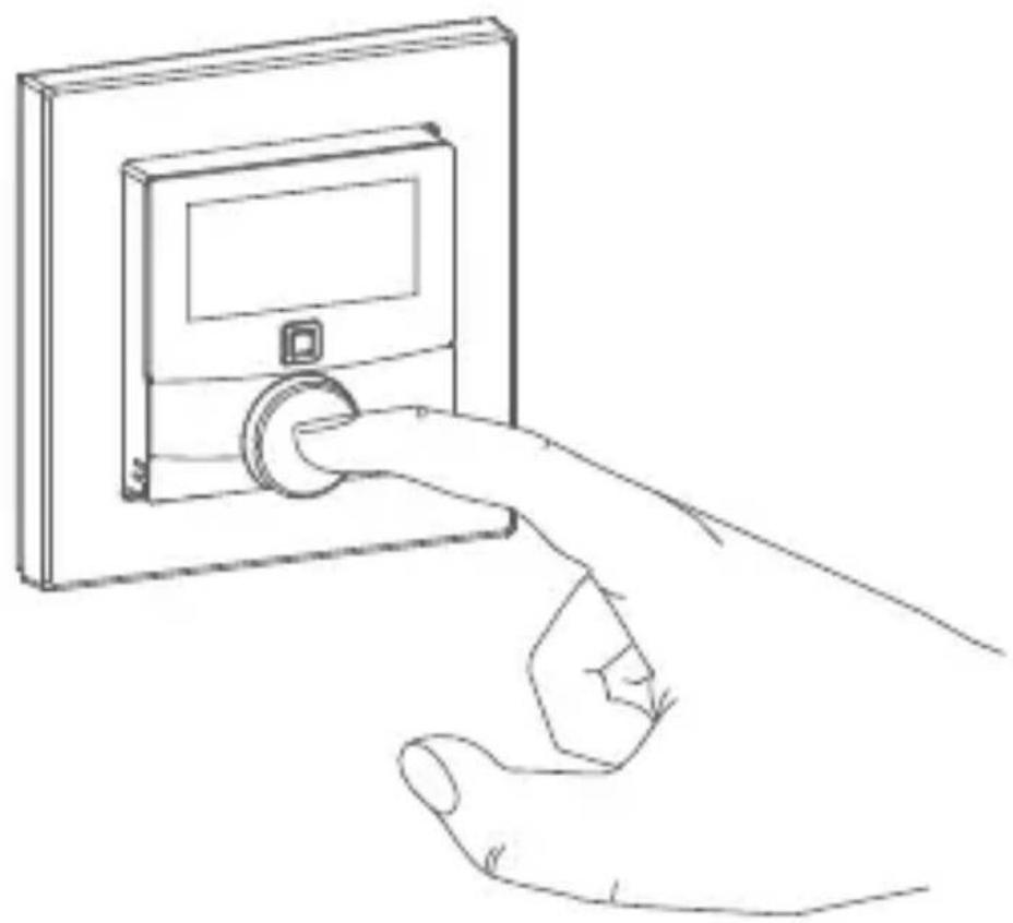
- Press and hold down the control wheel (E) to open the configuration menu (see fig. 6).
- Select the desired symbol by turning the control wheel and pressing it briefly if you want to adjust the settings of the following menu items.

Press and hold down the control wheel to get back to the previous level.
The menu automatically closes without applying changes if there is no operation for more than 1 minute.
| 6.1 Auto |  | mode |
| 6.2 |  | Manual operation |
| 6.3 Hol |  | ode |
| 6.4 |  | Operating lock |
| 6.5 |  | Valve type and domestic heating system |
| 6.6 Pro |  | mming of heating profiles |
| 6.7 |  | Date and time |
| 6.8 |  | Offset temperature |
| 6.9 |  | Selecting the desired temperature display |
| 6.10 |  | Configuring the floor heating actuator |
| 6.11 |  | Communication test |
6.1 Automatic mode
In automatic mode, the temperature is controlled in accordance with the set week profile (see „6.6.3 Week profile“ on page 73). Manual changes that are set via the control wheel (E) are activated until the next point at which the profile changes. Afterwards, the defined heating profile will be activated again. To activate the automatic mode, please proceed as follows:
- Press and hold down the control wheel (E) to open the configuration menu (see fig. 6).
- Select the AUTO symbol by turning the control wheel and confirm by pressing the control wheel briefly.
6.2 Manual operation
In manual mode, the temperature is controlled in accordance with the current temperature set via the control wheel (E). The temperature remains activated until the next manual change. To activate the manual mode, please proceed as follows:
- Press and hold down the control wheel (E) to open the configuration menu (see fig. 6).
- Select the MANU symbol by turning the control wheel and confirm by pressing the control wheel briefly.
- Turn the control wheel to set the desired temperature.

You can fully close/switch-off or open/switch-on the valve/relay by turning the control wheel (E) as far as it will go in an anti-clockwise or clockwise direction.
6.3 Holiday mode
The holiday mode can be used if you want to maintain a fixed temperature for a certain period (e.g. during your holidays or a party). To activate the holiday mode, please proceed as follows:
- Press and hold down the control wheel (E) to open the configuration menu (see fig. 6).
-
Select the symbol by turning the control wheel and confirm by pressing the control wheel briefly.
-
Select the start time and date by turning the control wheel and confirm by pressing the control wheel briefly. "S" indicates a start time.
- Select the end time and date by turning the control wheel and confirm by pressing the control wheel briefly. "E" indicates an end time.
- Set the temperature that you want to maintain during the defined time using the control wheel and confirm by pressing the control wheel briefly.
- By turning the control wheel you can select the rooms for activating the holiday mode.
- Selection "OnE":
The holiday mode is activated for the current wall thermostat.
- Selection "ALL" (only relevant in connection with a floor heating actuator):
The holiday mode is activated for all wall thermostats that are connected to the floor heating actuator.
6.4 Operating lock
Operation of the device can be locked to avoid settings being changed unintended (e.g. through involuntary touch). To activate the operating lock, please proceed as follows:
- Press and hold down the control wheel (E) to open the configuration menu (see fig. 6).
- Select the symbol by turning the control wheel
and confirm by pressing the control wheel briefly.
- Turn the control wheel to select "On" in order to activate the operating lock or "OFF" to deactivate the operating lock.

If the operating lock is activated you can only enter the menu item "Operating lock" (💡) via the configuration menu. You can deactivate the operating lock here.
6.5 Valve type and domestic heating system
In this menu item you can select the valve type (normally closed or normally open) that is connected to the switch relay as well as your domestic heating system.
- Press and hold down the control wheel (E) to open the configuration menu (see fig. 6).
- Select the “SET” symbol by turning the control wheel and confirm by pressing the control wheel briefly.
- Turn the control wheel and select
- "Unit" and "nc" or "no" for normally closed or normally open as well as
- "ArEA" and a number between 0 and 4 for your domestic heating system with the following meaning:
| Number Meaning | |
| 0 Standard floor heating | |
| 1 Low energy floor heating | |
| 2 Radiator | |
| 3 Passive convector | |
| 4 Active convector | |
6.6 Programming the week profiles
You can use this menu item for configuring heating and cooling profiles and to adjust the week profiles according to your personal needs.
- Press and hold down the control wheel (E) to open the configuration menu (see fig. 6).
- Select the Prg symbol by turning the control wheel and confirm by pressing the control wheel briefly.
-
Turn the control wheel and select
-
"type" for switching between heating ("HEAT") or cooling ("COOL"),
- "Pr.nr" to set the week profile number ("no. 1, no. 2 ... no. 6"),
- "Pr.Ad" for individual settings of the week profile and
- "OSSF" for activating ("On") or deactivating ("OFF") the optimum start/stop function.
6.6.1 Heating or cooling
You can use your floor heating system to heat rooms during winter or to cool rooms during summer.
- Select "HEAT" for heating and "COOL" for cooling in the menu item "type" by turning the control wheel (E) and confirm by pressing the control wheel briefly.
6.6.2 Week profile number
You can select between the following 6 pre-configured profiles.
- Select the number of the required profile in the menu item "Pr.nr." by turning the control wheel (E) and confirm by pressing the control wheel briefly.

If the selected profile is a heating profile, the room is heated as soon as the temperature falls below the defined value. If the selected profile is a cooling profile, the room is cooled as soon as the temperature increases the defined value.
After switching from "heating" to "cooling" in the menu, the profiles are changed from profile 1 to 4, profile 2 to 5 and from profile 3 to 6 automatically.
Profile 1
Pre-configured heating via radiator thermostat
| Monday to Friday Temp. | |
| 00:00 - 06:00 17.0 °C | |
| 06:00 - 09:00 21.0 °C | |
| 09:00 - 17:00 17.0 °C | |
| 17:00 - 22:00 21.0 °C | |
| 22:00 - 23:59 17.0 °C |
| Saturday to Sunday Temp. | |
| 00:00 - 06:00 17.0 °C | |
| 06:00 - 22:00 21.0 °C | |
| 22:00 - 23:59 17.0 °C |
Profile 2
Pre-configured heating via floor heating
| Monday to Friday Temp. | |
| 00:00 - 05:00 19.0 °C | |
| 05:00 - 08:00 21.0 °C | |
| 08:00 - 15:00 19.0 °C | |
| 15:00 - 22:00 21.0 °C | |
| 22:00 - 23:59 19.0 °C | |
| Saturday to Sunday Temp. | |
| 00:00 - 06:00 19.0 °C | |
| 06:00 - 23:00 21.0 °C | |
| 23:00 - 23:59 19.0 °C |
Profile 3
Alternative profile
| Monday to Sunday Temp. | |
| 00:00 - 06:00 17.0 °C | |
| 06:00 - 22:00 21.0 °C | |
| 22:00 - 23:59 17.0 °C |
Profile 4
Alternative cooling profile 1
| Monday to Friday Temp. | |
| 00:00 - 06:00 17.0 °C | |
| 06:00 - 09:00 21.0 °C | |
| 09:00 - 17:00 17.0 °C | |
| 17:00 - 22:00 21.0 °C | |
| 22:00 - 23:59 17.0 °C |
| Saturday to Sunday Temp. | |
| 00:00 - 06:00 17.0 °C | |
| 06:00 - 22:00 21.0 °C | |
| 22:00 - 23:59 17.0 °C |
Profile 5
Pre-configured cooling via floor heating
| Monday to Friday Temp. | |
| 00:00 - 05:00 23.0 °C | |
| 05:00 - 08:00 21.0 °C | |
| 08:00 - 15:00 23.0 °C | |
| 15:00 - 22:00 21.0 °C | |
| 22:00 - 23:59 23.0 °C |
| Saturday to Sunday Temp. | |
| 00:00 - 06:00 23.0 °C | |
| 06:00 - 23:00 21.0 °C | |
| 23:00 - 23:59 23.0 °C |
Profile 6
Alternative cooling profile 1
| Monday to Sunday Temp. | |
| 00:00 - 06:00 17.0 °C | |
| 06:00 - 22:00 21.0 °C | |
| 22:00 - 23:59 17.0 °C |
6.6.3 Week profile
In the week profile, for each weekday of the selected heating or cooling profile up to 6 heating phases (13 change settings) can be set separately. The programming is carried out for the selected days, whereby temperature settings have to be set for the entire period between 00:00 and 23:59h.
- Select the number of the required profile in the menu item "Pr.Ad by turning the control wheel (E) and confirm by pressing the control wheel briefly.
- In the menu item "dAy" you can select single days of the week, all weekdays, the weekend or the entire week for your heating profile and confirm by pressing the control wheel briefly.
- Confirm the start time 00:00 by pressing the control wheel briefly.
- Select the desired temperature for the start time by turning the control wheel and confirm by pressing the control wheel briefly.
- The next time is shown in the display. You can change this time using the control wheel.
- Select the desired temperature for the next period by turning the control wheel and confirm by pressing the control wheel briefly.
- Repeat this procedure until temperatures are stored for the entire period between 0:00 and 23:59 h.
6.6.4 Optimum start/stop function
To reach the desired temperature in the room at the defined time you can activate the optimum start/stop function.
- Select "On" for activating or "OFF" for deactivating the function in the menu item "OSSF" by turning the control wheel (E) and confirm by pressing the control wheel briefly.
6.7 Date and time
To set the date and time, please proceed as follows:
- Press and hold down the control wheel (E) to open the configuration menu.
- Select the ⏻ symbol by turning the control wheel and confirm by pressing the control wheel briefly.
- Set the year, month, day and hour by turning the control wheel and confirm by pressing the control wheel briefly.
6.8 Offset temperature
As the temperature is measured on the wall thermostat, the temperature distribution can vary throughout a room. To adjust this, a temperature offset of ±3.5\ °C can be set. If a nominal temperature of e.g. 20\ °C is set but the room presents with only 18\ °C , an offset of -2.0\ °C needs to
be set. An offset temperature of 0.0° is set in the factory settings. To adjust the offset temperature, please proceed as follows:
- Press and hold down the control wheel (E) to open the configuration menu (see fig. 6).
- Select the Offset symbol by turning the control wheel and confirm by pressing the control wheel briefly.
- Turn the control wheel until the desired temperature appears (+3.5 °C maximum).
- Confirm by pressing the control wheel briefly.
6.9 Selecting the desired temperature display
You can adjust the temperature to be displayed. You can also define whether the humidity value shall be displayed or not.
- Press and hold down the control wheel (E) to open the configuration menu (see fig. 6).
-
Select the LCD symbol by turning the control wheel and confirm by pressing the control wheel briefly.
• Turn the control wheel and select -
"ACT" to display the actual temperature,
- "SEt" to display the setpoint temperature,
- "ACtH" for alternating between the actual temperature and humidity display and confirm by pressing the control wheel briefly.
6.10 Configuring the floor heating actuator
You can use this menu item for configuring your Home-matic IP Floor Heating Actuator.
- Press and hold down the control wheel (E) to open the configuration menu (see fig. 6).
- Select the FAL symbol by turning the control wheel and confirm by pressing the control wheel briefly.
- If the wall thermostat is connected to more than one floor heating actuator, please select the required floor heating using the control wheel.
- Please define if you want to configure the device parameters ("UnP1/UnP2") or the channel parameters ("ChAn").
- You can individually adjust the line-up time/follow-up time, eco temperatures, intervals etc.
For further information regarding the configuration options, please refer to the user manual of the floor heating actuator.
6.11 Communication test
You can check the connection between your Homematic IP Wall Thermostat and the Homematic IP Floor Heating Actuator. During this test, the wall thermostat transmits a switching command to the floor heating actuator. Depending on the current status of the actuator, the device is switched on or off for confirmation after receiving the
command.
- Press and hold down the control wheel (E) to open the configuration menu (see fig. 6).
- Select the symbol by turning the control wheel and confirm by pressing the control wheel briefly.
7 Operation
After configuration, simple operations are available directly on the device.

If the wall thermostat is in standby mode, please press the control wheel (E) once before operation to activate the device.
- Temperature: Turn the control wheel (E) of the wall thermostat to the right or to the left to manually change the temperature. In automatic mode, the manually set temperature will remain the same until the next point at which the profile changes. Afterwards, the defined heating profile will be activated again. During manual operation, the temperature remains activated until the next
manual change.
- Boost function for Homematic IP Radiator Thermostats*: Press the control wheel (E) of the wall thermostat briefly to activate the boost function for heating up the radiator quickly and briefly by opening the valve. There will be a pleasant room temperature right away because of the radiated heat. *The boost function can only be executed in connection with a Homematic IP Radiator Thermostat.
8 Troubleshooting
8.1 Command not confirmed
If at least one receiver does not confirm a command, the device LED (D) lights up red at the end of the failed transmission process. The failed transmission may be caused by radio interference (see „11 General information about radio operation“ on page 84). This may be caused by the following:
- Receiver cannot be reached.
- Receiver is unable to execute the command (load failure, mechanical blockade, etc.).
- Receiver is defective.
8.2 Duty cycle
The duty cycle is a legally regulated limit of the transmission time of devices in the 868 MHz range. The aim of this regulation is to safeguard the operation of all devices working in the 868 MHz range.
In the 868 MHz frequency range we use, the maximum transmission time of any device is 1% of an hour (i.e. 36 seconds in an hour). Devices must cease transmission when they reach the 1% limit until this time restriction comes to an end. Homematic IP devices are designed and produced with 100% conformity to this regulation.
During normal operation, the duty cycle is not usually reached. However, repeated and radio-intensive teach-in processes mean that it may be reached in isolated instances during start-up or initial installation of a system. If the duty cycle is exceeded, this is indicated by three slow flashes of the device LED (D), and may manifest itself in the device temporarily working incorrectly. The device starts working correctly again after a short period (max. 1 hour).
8.3 Error codes and flashing sequences
| Error and flashing codes | Meaning Solution | |
| Antenna symbol flashing (💡) | Communication error with Homematic IP Access Point/floor heating actuator | Please check the connection to the Homematic IP Access Point/floor heating actuator. |
| Battery symbol (💡) | Supply voltage interrupted | Restore the supply voltage. |
| Flashing humidity symbol (%) | Humidity limit (60 %) in the room is exceeded | Ventilate the room and switch from cooling to heating mode, if required |
| Flashing condensation and cooling symbol (💡_) | Humidity input of Multi IO Box has been activated | Ventilate the room and switch from cooling to heating mode, if required |
| Lock symbol (💡) | Operating lock activated | Deactivate the operating lock via the app or the menu. |
| Short orange flashing | Radio transmission/at-tempting to transmit/data transmission | Wait until the transmission is completed. |
| 1x long green lighting | Operation confirmed | You can continue operation. |
| 1x long red lighting | Operation failed | Please try again (s. „8.1 Command not confirmed" on page 78). |
| Short orange flashing (every 10 seconds) | Teach-in mode active | Please enter the last four numbers of the device serial number for confirmation (see „5.4 Teaching-in" on page 60). |
| 1x long red lighting | Transmission failed or duty cycle limit is reached | Please try again (see sec. „8.1 Command not confirmed" on page 78 or „8.2 Duty cycle" on page 79). |
| 6x long red flashing | Device defective | Please see your app for error message or contact your retailer. |
| 1x orange and 1 x green lighting (after inserting batteries) | Test display After | the test display has stopped, you can continue. |
9 Restore factory settings

The factory settings of the device can be restored. If you do this, you will lose all your settings.
To restore the factory settings of the wall thermostat, please proceed as follows:
- Pull the electronic unit (B) forward (see fig. 7).
- Place the electronic unit back on the voltage supply unit (F) and press and hold down the system button (D) for 4 seconds (see fig. 5) at the same time, until the LED will quickly start flashing orange.
- Release the system button again.
- Press and hold down the system button again for 4 seconds, until the status LED lights up green.
- Release the system button to finish the procedure.
The device will perform a restart.
10 Maintenance and cleaning

The device does not require you to carry out any maintenance other than replacing the battery when necessary. Enlist the help of an expert to carry out any maintenance or repairs.
Clean the device using a soft, lint-free cloth that is clean and dry. You may dampen the cloth a little with lukewarm water in order to remove more stubborn marks. Do not use any detergents containing solvents, as they could corrode the plastic housing and label.
11 General information about radio operation
Radio transmission is performed on a non-exclusive transmission path, which means that there is a possibility of interference occurring. Interference can also be caused by switching operations, electrical motors or defective electrical devices.

The range of transmission within buildings can differ greatly from that available in the open air. Besides the transmitting power and the reception characteristics of the receiver, environmental factors such as humidity in the vicinity have an important role to play, as do on-site structural/screening conditions.
eQ-3 AG hereby declares that this device complies with the essential requirements and other relevant regulations of Directive 1999/5/EC. You can find the full declaration of conformity at www.eQ-3.de.
12 Technical specifications
Device short description: HmIP-BWTH
Supply voltage: 230 V/50 Hz
Current consumption: 1 A max.
Degree of protection: IP20
Max. switching capacity: 230 W
Kind of load: ohmic load
Cable type and cross section: rigid and flexible cable, 0.75-1.50 mm 4
Installation: only in normal commer-
cial switch boxes (device
boxes) in accordance
with DIN 49073-1.
Ambient temperature: 0 to 50 °C
Dimensions (W x H x D):
Without frame: 55 x 55 x 54 mm
Including frame: 86 x 86 x 54 mm
Weight: 136 g
Radio frequency: 868.3 MHz/869.525 MHz
Receiver category: SRD category 2
Typ. open area RF range: 130 m
Duty cycle: < 1 % per h/< 10 % per h
Method of operation: Type 1.B
Pollution degree: 2
Temperature of
ball pressure test: 125 °C
Withstand voltage: 4000 V
Construction of the regulation
and control device: independently mounted
electronic regulation and control device
Subject to technical changes.
Instructions for disposal

Do not dispose of the device with regular domestic waste! Electronic equipment must be disposed of at local collection points for waste electronic equipment in compliance with the Waste Electrical and Electronic Equipment Directive.
Information about conformity

The CE sign is a free trading sign addressed exclusively to the authorities and does not include any warranty of any properties.

For technical support, please contact your retailer.
Free download of the Homematic IP app!


Bevollmächtigter des Herstellers: Manufacturer's authorised representative:

eQ-3 AG Maiburger Straße 29 26789 Leer / GERMANY www.eQ-3.de


- LIEFERUMFANG
- ANZAHL BEZEICHNUNG
- INHALTSVERZEICHNIS
- TABLE OF CONTENTS
- 1 INFORMATION ABOUT THIS MANUAL
- SYMBOLS USED
- ATTENTION
- PLEASE NOTE
- 2 HAZARD INFORMATION
- 3 FUNCTION AND DEVICE OVERVIEW
- DEVICE OVERVIEW (SEE FIGURE 1)
- DISPLAY OVERVIEW (SEE FIGURE 2)
- 4 GENERAL SYSTEM INFORMATION
- 5 START-UP
- 5.1 INSTALLATION INSTRUCTIONS
- CONTACT AN ELECTRICAL INSTALLER
- SPECIALIST KNOWLEDGE REQUIRED FOR INSTALLATION
- 5.2 INSTALLATION
- 5.3 BEHAVIOUR AFTER SWITCHING ON THE MAINS VOLTAGE
- 5.4 TEACHING-IN
- 5.4.1 PAIRING WITH A HOMEMATIC IP FLOOR HEATING ACTUATOR
- 5.4.2 TEACHING-IN TO THE HOMEMATIC IP ACCESS POINT
- 6 OPERATING MODES AND CONFIGURATION
- 6.1 AUTOMATIC MODE
- 6.2 MANUAL OPERATION
- 6.3 HOLIDAY MODE
- 6.4 OPERATING LOCK
- 6.5 VALVE TYPE AND DOMESTIC HEATING SYSTEM
- 6.6 PROGRAMMING THE WEEK PROFILES
- 6.6.1 HEATING OR COOLING
- 6.6.2 WEEK PROFILE NUMBER
- PROFILE 1
- PROFILE 2
- PROFILE 3
- PROFILE 4
- PROFILE 5
- PROFILE 6
- 6.6.3 WEEK PROFILE
- 6.6.4 OPTIMUM START/STOP FUNCTION
- 6.7 DATE AND TIME
- 6.8 OFFSET TEMPERATURE
- 6.9 SELECTING THE DESIRED TEMPERATURE DISPLAY
- 6.10 CONFIGURING THE FLOOR HEATING ACTUATOR
- 6.11 COMMUNICATION TEST
- COMMAND
- 7 OPERATION
- 8 TROUBLESHOOTING
- 8.1 COMMAND NOT CONFIRMED
- 8.2 DUTY CYCLE
- 8.3 ERROR CODES AND FLASHING SEQUENCES
- 9 RESTORE FACTORY SETTINGS
- 10 MAINTENANCE AND CLEANING
- 11 GENERAL INFORMATION ABOUT RADIO OPERATION
- 12 TECHNICAL SPECIFICATIONS
- SUBJECT TO TECHNICAL CHANGES
- INSTRUCTIONS FOR DISPOSAL
- INFORMATION ABOUT CONFORMITY
Brand : EQ-3
Model : HMIP-BWTH
Category : Thermostat