ERT310 - Router B&B Electronics - Free user manual and instructions
Find the device manual for free ERT310 B&B Electronics in PDF.


| Product Type | Industrial Cellular Router (SPECTRE Series) |
| Dimensions (H x W x D) | 42 x 76 x 113 mm |
| Weight | 280 g |
| Power Supply | 10-30 V DC, Class 2 power supply only |
| Power Consumption | Receive: 2.3 W; Transmit: up to 5.5 W |
| Ethernet Port | 1x RJ45, 10/100 Mbit/s |
| USB Port | USB 2.0 Type A Host |
| Auxiliary Ports | 2x RJ45, configurable as RS-232, RS-485/422, Ethernet, or I/O (model dependent) |
| I/O Port | 3-pin: 1 binary input, 1 binary output, 1 ground |
| SIM Card Slots | Dual SIM (SIM1 and SIM2) |
| Antenna Connectors | Main (ANT) and Diversity (DIV): SMA; Wi-Fi (AUX): RP-SMA |
| Wireless Standards | LTE, HSPA+, UMTS, GPRS, Wi-Fi 802.11 b/g/n (on -W models) |
| VPN Support | IPsec, OpenVPN, L2TP |
| Configuration Interface | Web browser, Telnet |
| Operating Temperature | -30 °C to +60 °C |
| Storage Temperature | -40 °C to +85 °C |
| Protection Rating | IP20 (free), IP56 (in switchboard) |
| Compliance | FCC Part 15, Industry Canada, Class I Div 2, EN 60950, EN 301 511, EN 301 908 |
| Safety | Class I, Division 2 hazardous locations; use only in suitable enclosure |
| Maintenance | Do not use harsh chemicals; handle SIM card carefully |
Frequently Asked Questions - ERT310 B&B Electronics
User questions about ERT310 B&B Electronics
0 question about this device. Answer the ones you know or ask your own.
Ask a new question about this device
Download the instructions for your Router in PDF format for free! Find your manual ERT310 - B&B Electronics and take your electronic device back in hand. On this page are published all the documents necessary for the use of your device. ERT310 by B&B Electronics.
USER MANUAL ERT310 B&B Electronics
natural_image
Blue B2B Electronics 3G device with ports, connectors, and labeled ports (no readable text beyond labels)
B&B ELECTRONICS
B
B&B ELECTRONICS
International Headquarters
B&B Electronics Mfg. Co. Inc.
707 Dayton Road
Ottawa, IL 61350 USA
Phone (815) 433-5100 -- General Fax (815) 433-5105
Website: www.bb-elec.com
European Headquarters
B&B Electronics Ltd.
Westlink Commercial Park
Oranmore, Co. Galway, Ireland
Phone +353 91-792444 -- Fax +353 91-792445
Website: www.bb-europe.com
Doc: 710-10001-01 Rev 4.0 – December 2013
©2013 B&B Electronics Mfg. Co. Inc. No part of this publication may be reproduced or transmitted in any form or by any means, electronic or mechanical, including photography, recording, or any information storage and retrieval system without written consent. Information in this manual is subject to change without notice, and does not represent a commitment on the part of B&B Electronics Mfg. Co. Inc.
B&B Electronics Mfg. Co. Inc. shall not be liable for incidental or consequential damages resulting from the furnishing, performance, or use of this manual.
All brand names used in this manual are the registered trademarks of their respective owners. The useof trademarks or other designations in this publication is for reference purposes only and does not constitute an endorsement by the trademark holder.
This device complies with part 15 of the FCC Rules. Operation is subject to the following two conditions: (1) This device may not cause harmful interference, and (2) this device must accept any interference received, including interference that may cause undesired operation.
This device complies with Industry Canada licence-exempt RSS standard(s). Operation is subject to the following 2 conditions: (1) this device may not cause interference, and (2) this device must accept any interference, including interference that may cause undesired operation of the device.
Contents
1.0 Symbols Used 6
2.0 Safety instructions 7
2.1 Compliance 7
2.2 Product disposal instructions 7
3.0 Router Description 8
3.1 Description 8
3.2 Examples of possible applications: 8
3.3 Contents of package 9
3.4 Model numbers 10
3.5 Dimensions 12
4.0 Mounting Recommendations 13
5.0 User Interfaces 16
5.1 Connectors 16
5.2 Status Indicators 18
5.3 Power Connector 20
5.4 Antenna Connector 21
5.5 SIM Card Reader 22
5.6 Ethernet Port 23
5.2.1 Auxiliary Port Status Indicators 19
5.7.1 RS-232 Ports 24
5.7.2 RS-485/422 Ports 26
5.7.3 I/O Port 31
5.7.3.1 Analog Inputs 31
5.7.3.2 Binary Input 31
5.7.3.3 Counter Input 31
5.7.3.4 Binary Output 31
5.7.3.5 Selecting the Binary Input Current 32
5.7.3.6 Input/Output Connector 33
5.8 USB Port 40
5.9 I/O Port 42
6.0 Resetting or Rebooting the Router 44
7.0 First Use 45
7.1 Starting the router 46
7.2 Configuring the router 46
7.3 Technical Parameters 47
8.0 Troubleshooting 49
8.1 FAQ 49
9.0 Customer Support 51
Figure List
Fig. 1: Contents of package....9
Fig. 2: Basic dimensions, metal box 12
Fig. 3: Space around antenna 13
Fig. 4: Cable routing....14
Fig. 5: Space in front connectors .... 15
Fig. 6: Front panel SPECTRE Cellular Router .... 16
Fig. 7: Front panel SPECTRE Cellular Router with Wi-Fi 17
Fig. 8: Power connector....20
Fig. 9: Connection of power supply connector 20
Fig. 10: Connection of power supply 20
Fig. 11: External antenna....21
Fig. 12: Connecting the antenna....21
Fig. 13: Ejected SIM card holder 22
Fig. 14: Ethernet connector 23
Fig. 15: Ethernet Cable Connection....23
Fig. 16: Example of router connection 24
Fig. 17: RS232 port connector.... 25
Fig. 18: Meter connection to router 25
Fig. 19: PC connection to router 26
Fig. 20: RS-232 equipment connection to router 26
Fig. 21: Jumper Position for external supply 27
Fig. 22: Jumper Position for RS-485....27
Fig. 23: Jumper Position for internal supply 27
Fig. 24: Jumper Position for RS-422....27
Fig. 25: RS485/422 connector....28
Fig. 26: Connection to the router with data cable length less than 10 m ..... 28
Fig. 27: Connection to the router with data cable length more than 10 m ..... 29
Fig. 28: Connection to the router with data cable length less than 10 m ..... 30
Fig. 29: Connection to the router with data cable length more than 10 m ..... 30
Fig. 30: CNT I/O board 32
Fig. 31: CNT connector .... 33
Fig. 32: Connection of the I/O Port circuitry 34
Fig. 33: USB connector 40
Fig. 34: Connecting a PLC to the router....41
Fig. 35: Connecting USB memory stick to the router 41
Fig. 36: I/O connection 42
Fig. 37: Connection I/O cable 42
Fig. 38: Connection of binary input and output of router 43
Fig. 39: Router reset 44
Fig. 40: Router connections 45
Table list
Table 1: Auxiliary port possibilities....10
Table 2: Model numbers ...... 10
Table 3: LTE Model numbers for Verizon....11
Table 4: LTE Model numbers for AT&T 11
Table 5: Front panel description....16
Table 6: Router status indication....18
Table 7: Ethernet LED status indication 19
Table 8: RS-232 LED status indication....19
Table 9: I/O Port LED status indication 19
Table 10: RS-485/422 LED status indication.... 19
Table 11: RS-485/422 LED status indication....19
Table 12: Connection of power connector....20
Table 13: Ethernet connector 23
Table 14: RS232 connector Pinout 25
Table 15: Connector Pinout in RS-485 Mode 28
Table 16: Connector Pinout in RS-422 Mode 29
Table 17: Input/Output Connector Pinout 33
Table 18: MODBUS Input/Output Address space 39
Table 19: Connection of USB connector....40
Table 20: I/O port Connection 42
Table 21: Ways to reset or restart the router....44
Table 22: General Specifications 47
Table 23: Cellular Module Specifications....48
Table 24: Processor Specifications....48
Table 25: I/O Port Specifications 48
Table 26: WiFi Specifications....48

1.0 Symbols Used
Danger – Information regarding user safety or potential damage to the router.
Attention – Problems that can arise in specific situations.
Information – Useful tips or information of special interest.
GPL license
Source codes under GPL license are available free of charge by sending an email to support@bb-elec.com.
Router version
The properties and settings associated with the cellular network connection are not available in non-cellular SPECTRE RT routers.
PPPoE configuration is only available on SPECTRE RT routers. It is used to set the PPPoE connection over Ethernet.

Declared quality system ISO 9001

This device complies with part 15 of the FCC Rules. Operation is subject to the following two conditions: (1) This device may not cause harmful interference, and (2) this device must accept any interference received, including interference that may cause undesired operation.

2.0 Safety instructions
2.1 Compliance
Please observe the following instructions:

THIS EQUIPMENT IS SUITABLE FOR USE IN CLASS I, DIVISION 2, GROUPS A, B, C, AND D HAZARDOUS LOCATIONS, OR NON-HAZARDOUS LOCATIONS ONLY.
WARNING – EXPLOSION HAZARD – DO NOT DISCONNECT EQUIPMENT UNLESS POWER HAS BEEN REMOVED OR THE AREA IS KNOWN TO BE NON-HAZARDOUS.
WARNING – EXPLOSION HAZARD – SUBSTITUTION OF ANY COMPONENTS MAY IMPAIR SUITABILITY FOR CLASS I, DIVISION 2.
- These devices are open-type devices that are to be installed in an enclosure suitable for the environment.
- The router must be used in compliance with all applicable international and national laws and in compliance with any special restrictions regulating the use of the router in prescribed applications and environments.
- To prevent possible injury and damage to appliances and to ensure compliance with all relevant provisions, use only the original accessories. Unauthorized modifications or the use of unapproved accessories may result in damage to the router and a breach of applicable regulations. Unauthorized modifications or use of unapproved accessories may void the warranty.
- Caution! The SIM card could be swallowed by small children.
- Input voltage must not exceed 30V DC max.
- Do not expose the router to extreme ambient conditions. Protect the router against dust, moisture and high temperature.
- The router should not be used in locations where flammable and explosive materials are present, including gas stations, chemical plants, or locations in which explosives are used.
- Switch off the router when travelling by plane. Use of the router in a plane may endanger the operation of the plane or interfere with the mobile telephone network, and may be unlawful.
- When using the router in the close proximity of personal medical devices, such as cardiac pacemakers or hearing aids, proceed with heightened caution.
- The router may cause interference when in the close proximity of TV sets, radio receivers or personal computers.
- It is recommended that you create a backup copy of all the important settings stored in the router's memory.
2.2 Product disposal instructions
The WEEE (Waste Electrical and Electronic Equipment: 2002/96/EC) directive has been introduced to ensure that electrical/electronic products are recycled using the best available recovery techniques to minimize the impact on the environment. This product contains high quality materials and components which can be recycled. At the end of its life, this product MUST NOT be mixed with other commercial waste for disposal. Check the terms and conditions of your supplier for disposal information.
3.0 Router Description
3.1 Description
The SPECTRE Cellular industrial router is used to wirelessly connect Ethernet equipment and other devices to the Internet or intranet. Thanks to the high data transfer speed of up to 100 Mbit/s download (LTE models) and 50 Mbit/s upload (LTE models), it is an ideal wireless solution for traffic and security camera systems, individual computers, LAN networks, automatic teller machines (ATM) and other self-service terminals.
The standard configuration includes one 10/100 Ethernet port, one USB Host port, one binary Input/output (I/O) port and dual SIM card holders. Network redundancy is provided by the second SIM card holder. It also contains 2 auxiliary ports for connecting to other types of networks such as RS-232, RS-485/422, Digital/Analog I/O, or they can be configured to provide additional switched Ethernet ports. The function of each port is dependent upon the specific router model.
Configuration of the router may be done via a password-protected Web interface. The router supports the creation of VPN tunnels using IPsec, OpenVPN and L2TP to ensure safe communication. The Web interface provides detailed statistics about the router's activities, signal strength, etc. The router supports DHCP, NAT, NAT-T, DynDNS, NTP, VRRP, control by SMS, and many other functions.
The router provides diagnostic functions which include automatically monitoring the PPP connection, automatic restart in case of connection losses, and a hardware watchdog that monitors the router status. The user may insert Linux scripts to control various router functions and create up to four different configurations for the same router. These configuration files can include different SMS functionality and binary input configurations. You may switch between different configurations whenever necessary. The router can automatically upgrade its configuration and firmware from your central server. This allows for mass reconfiguration of numerous routers at the same time. Additional software like SmartCluster VPN Server and R-SeeNet for router monitoring are also supported.
3.2 Examples of possible applications:
- Mobile office
- Fleet management
- Security system
- Telematics
- Telemetrics
- Remote monitoring
• Vending and dispatcher machines
3.3 Contents of package
The basic router package includes:
- Router
- Power supply
• Crossover UTP cable - External antennas
- Clips for the DIN rail
- Documentation CD
- Quick Start Guide
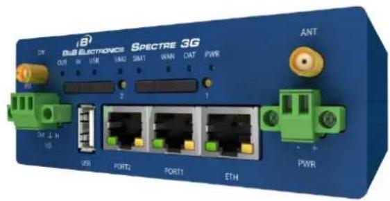
text_image
8x8 ELECTRONICS SPECTRE 3G OUT OUT USE LABS SIM1 UAM DAT PWR ANT 2 1 OUT L H USB USB PORT2 PORT1 ETH PWR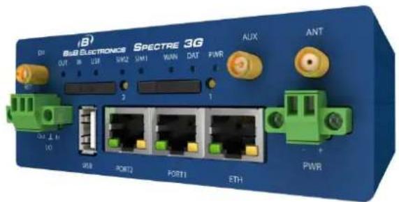
text_image
iB Spectre 3G Spectre ELECTRONICS DIN OUT IN SUB SIM2 SIM1 WIN DAT PWR AUX ANT 2 1 Out L H V0 USB PORT2 PORT1 ETH PWRSpectre 3G with WiFi
Fig. 1: Contents of package
3.4 Model numbers
Standard Features on Spectre Routers: 10/100 Ethernet, USB Host Port, Binary I/O Port, Dual SIM Card slots
Auxiliary Port Functions (Model Dependent):
| The ports can be connected as follows. | |
| PORT 1 | RS232, RS485/422, ETHERNET, CNT, XC-SW (in combination with PORT 2) |
| PORT 2 | RS232, RS485/422, XC-SW (together with PORT 1) |
Table 1: Auxiliary port possibilities
| Spectre 3G Wireless RoutersAuxiliary Ports | ||
| Model No. | Port 1 | Port 2 |
| RT3G-300 | No connect | No connect |
| RT3G-302 | No connect | RS-232 |
| RT3G-304 | No connect | RS-422/485 |
| RT3G-311 | Ethernet | Ethernet |
| RT3G-322 | RS-232 | RS-232 |
| RT3G-324 | RS-232 | RS-422/485 |
| RT3G-330 | 12-bit I/O (AI, DI, DO) | No connect |
| RT3G-300-W | No connect | No connect |
| RT3G-310-W | Ethernet | No connect |
| RT3G-320-W | RS-232 | No connect |
| RT3G-330-W | 12-bit I/O (AI, DI, DO) | No connect |
| RT3G-340-W | RS-422/485 | No connect |
| “-W” Models Are Wi-Fi enabled | ||
Table 2: Model numbers
| Spectre LTE Wireless Routers (Verizon)Auxiliary Ports | ||
| Model No. | Port 1 | Port 2 |
| RTLTE1-300 | No connect | No connect |
| RTLTE1-302 | No connect | RS-232 |
| RTLTE1-304 | No connect | RS-422/485 |
| RTLTE1-311 | Ethernet | Ethernet |
| RTLTE1-322 | RS-232 | RS-232 |
| RTLTE1-324 | RS-232 | RS-422/485 |
| RTLTE1-330 | 12-bit I/O (AI, DI, DO) | No connect |
| RTLTE1-300-W | No connect | No connect |
| RTLTE1-310-W | Ethernet | No connect |
| RTLTE1-320-W | RS-232 | No connect |
| RTLTE1-330-W | 12-bit I/O (AI, DI, DO) | No connect |
| RTLTE1-340-W | RS-422/485 | No connect |
| “-W” Models Are Wi-Fi enabled | ||
Table 3: LTE Model numbers for Verizon
| Spectre LTE Wireless Routers (AT&T)Auxiliary Ports | ||
| Model No. | Port 1 | Port 2 |
| RTLTE2-300 | No connect | No connect |
| RTLTE2-302 | No connect | RS-232 |
| RTLTE2-304 | No connect | RS-422/485 |
| RTLTE2-311 | Ethernet | Ethernet |
| RTLTE2-322 | RS-232 | RS-232 |
| RTLTE2-324 | RS-232 | RS-422/485 |
| RTLTE2-330 | 12-bit I/O (AI, DI, DO) | No connect |
| RTLTE2-300-W | No connect | No connect |
| RTLTE2-310-W | Ethernet | No connect |
| RTLTE2-320-W | RS-232 | No connect |
| RTLTE2-330-W | 12-bit I/O (AI, DI, DO) | No connect |
| RTLTE2-340-W | RS-422/485 | No connect |
| “-W” Models Are Wi-Fi enabled | ||
Table 4: LTE Model numbers for AT&T
3.5 Dimensions
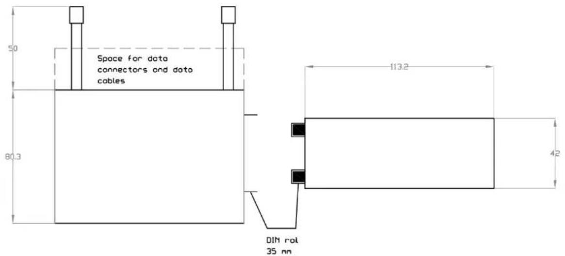
Basic dimensions, metal box
text_image
Space for data connectors and data cables 50 80.3 113.2 42 DIN rot 35 mmFig. 2: Basic dimensions, metal box
4.0 Mounting Recommendations
• The router may be placed on a work surface.
• Clips are included for mounting the router on a standard DIN rail.
The router may be installed in an industrial instrument panel.
For best performance, please consider the following guidelines:
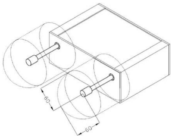
- When using the supplied whip antennas, maintain a distance of 6 cm from cables and metal surfaces on every side. When using an external antenna, unless in a switchboard, it is necessary to fit a lightning conductor.
- When mounting a router on sheet steel we recommend using an external antenna.
- If the router is installed in a metal instrument enclosure, an external antenna must be used and it must be mounted outside of the metal enclosure.
natural_image
Technical line drawing of a mechanical assembly with two cylindrical components and circular cutouts, no text or symbols present.Fig. 3: Space around antenna

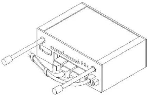
We recommend binding the cables together to avoid coupling noise onto the cables.
- Length: The combination of power supply and data cables can be a maximum of 1.5 meters.
- If the length of the data cables exceeds 1.5 meters or if the cable leads towards the switch panel, we recommend installing overvoltage protectors (surge suppressors).
- Do not bundle the data cables with 120/230V power cables.
- All wiring to sensors should use shielded twisted pairs.
natural_image
Technical line drawing of a mechanical or electrical component with two protruding rods and internal channels (no text or symbols)Fig. 4: Cable routing

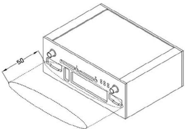
Leave enough space around the connectors for the handling of cables.
natural_image
Isometric line drawing of a rectangular electronic device with ports and a 50mm dimension label (no text or symbols beyond measurement lines)Fig. 5: Space in front connectors
We recommend using the switch panel's earth-bonding distribution frame for grounding the router's power supply, data cables and antenna.
5.0 User Interfaces
5.1 Connectors
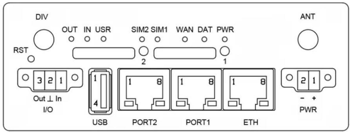
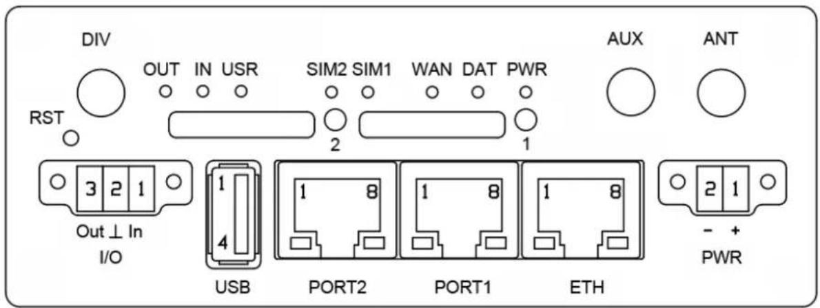
| FRONT PANEL | ||
| Label | Connector | Description |
| PWR | 2-pin | Power supply. |
| ETH | RJ45 | Connection to the local computer network. |
| PORT 1 | RJ45 | RS-232/422/485, ETHERNET, or I/O |
| PORT 2 | RJ45 | RS-232/422/485 or ETHERNET |
| ANT | SMA | Main cellular antenna. |
| DIV | SMA | Diversity cellular antenna. |
| AUX | RP-SMA | Wi-Fi antenna. |
| USB | USB-A Host | USB connector. |
| I/O | 3-pin | Binary input and output. |
| SIM1 | - | SIM card holder. |
| SIM2 | - | SIM card holder 2 |
Table 5: Front panel description
text_image
DIV RST OUT IN USR SIM2 SIM1 WAN DAT PWR 2 1 3 2 1 Out ⊥ In I/O USB PORT2 PORT1 ETH ANT 2 1 - + PWR 1 4Fig. 6: Front panel SPECTRE Cellular Router
text_image
DIV RST OUT IN USR SIM2 SIM1 WAN DAT PWR 2 1 AUX ANT 3 2 1 Out ⊥ In I/O 1 4 USB PORT2 1 8 PORT1 1 8 ETH 2 1 - + PWRFig. 7: Front panel SPECTRE Cellular Router with Wi-Fi
5.2 Status Indicators
| Label | Color | State | Description |
| PWR | Green | BlinkingOn | Router is readyRouter is initializing. |
| WAN | Red | Blinking | Communication in progress |
| DAT | Yellow | Flashing | PPP connection established |
| 1 x flash per second | Signal strength is from -50 dBm to -69 dBm | ||
| 2 x flash per second | Signal strength is from -70 dBm to -89 dBm or the difference between neighboring cells is exactly 3 dBm | ||
| 3x flash per second | Signal strength is from -90 dBm to -113 dBm or the difference between neighboring cells is smaller than 3 dBm | ||
| USR | Yellow | Function selected by user | |
| OUT | Green | On | Binary output active |
| IN | Green | On | Binary input active |
| ETH | Green | OnOff | Selected 100 Mbit/sSelected 10 Mbit/s |
| ETH | Yellow | OnBlinkingOff | The network cable is connectedData transmissionThe network cable is not connected |
| PORT | Green | LED functions for different router configurations appear in the charts below. | |
| PORT | Yellow | LED functions for different router configurations appear in the charts below. | |
| SIM1 | Yellow | On | SIM card 1 is active |
| SIM2 | Yellow | On | SIM card 2 is active |
Table 6: Router status indication
Note: The State indication of the PPP LED is updated every 10 seconds.
5.2.1 Auxiliary Port Status Indicators
5.2.1.1 Ethernet Ports
| LED port indicator | |
| Green LED | On...... selected 100 Mbit/sOff...... selected 10 Mbit/s |
| Yellow LED | On...... the network cable is connectedBlinking...... data transmissionOff...... the network cable is not connected |
Table 7: Ethernet LED status indication
5.2.1.2 RS-232 Ports
| LED port indicator | |
| Green LED | Blinks on Receive data |
| Yellow LED | Blinks on Transmit data |
Table 8: RS-232 LED status indication
5.2.1.3 I/O Ports
| LED port indicator | |
| Green LED | Indicates binary input 0 |
| Yellow LED | Indicates binary input 1 |
Table 9: I/O Port LED status indication
5.2.1.4 RS-485/422 Ports
| LED port indicator | |
| Green LED | Blinks on Receive data |
| Yellow LED | Blinks on Transmit data |
Table 10: RS-485/422 LED status indication
5.2.1.4 WiFi
| LED port indicator | |
| Green LED | Indicates WiFi Power On |
| Yellow LED | Always Off |
Table 11: RS-485/422 LED status indication
5.3 Power Connector
2-PIN PANEL SOCKET
| Pin number | Signal mark | Description |
| 1 | VCC (+) | Positive input of DC supply voltage (+10 to +30 VDC) |
| 2 | GND (-) | Negative input of DC supply voltage |
Table 12: Connection of power connector

Fig. 8: Power connector
The router requires a +10 V to +30 V DC supply. Protection against reversed polarity is built into the router.
The power consumption during receiving is 1W. The peak power consumption during data sending is 5.5W. For correct operation, the power source must be able to supply a peak current of 600mA.
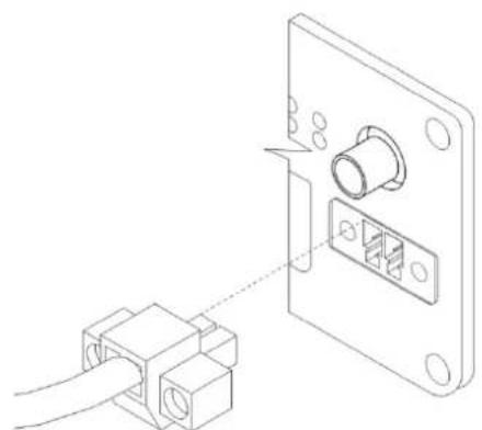
The power cable connects to the router via locking screws. (See Fig. 21)
natural_image
Technical line drawing showing a connector assembly with a cylindrical component inserted into a socket (no text or symbols present)Fig. 9: Connection of power supply connector
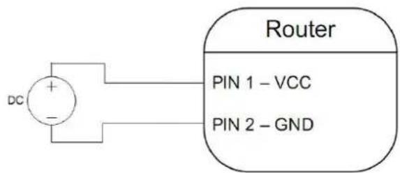
Circuit example:
flowchart
graph LR
    A["DC"] --> B["Router"]
    B --> C["PIN 1 – VCC"]
    B --> D["PIN 2 – GND"]
Fig. 10: Connection of power supply
The positive VCC input is marked by a red socket on the power.
5.4 Antenna Connector
The two large cellular antennas are connected to the router using the standard SMA antenna connectors on the front panel. The main cellular antenna connection is labeled ANT. The router cannot operate without a main antenna. The receive diversity antenna connection is labeled DIV. This antenna improves the receive sensitivity of the router and should be used in areas with weak signal strength.
On SPECTRE Cellular routers with Wi-Fi, a third antenna is connected to the AUX antenna connector on the front panel.

The AUX connector on the Wi-Fi units is a reverse-polarity SMA connector and should only be used with the smaller Wi-Fi antenna. Do not attempt to connect the cellular antennas to this connector as it can damage the connector and the antennas.
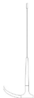
Example of antenna:
natural_image
Simple line drawing of a medical or laboratory instrument with a curved base and vertical rod (no text or symbols)Fig. 11: External antenna
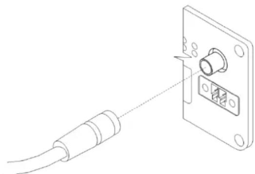
Connect the antenna's SMA connector to the router's SMA connector. (See figure below).
natural_image
Diagram of a cable being inserted into a socket with a connector (no text or symbols)Fig. 12: Connecting the antenna
The diversity antenna improves the wireless features of the router
5.5 SIM Card Reader
The SIM card reader supports 3 V and 1.8 V SIM cards. It is located on the front panel of the router. The router will not operate on UMTS networks unless an activated SIM card with an unblocked PIN is in the reader. The SIM cards may use different access point names (APN).
Changing the SIM card:
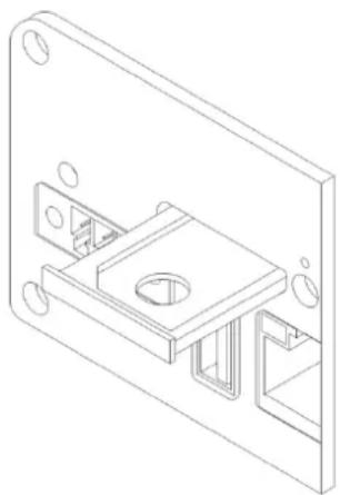
Press the small yellow button on the right hand side of the SIM reader slot to eject the SIM card holder. Insert the SIM card into the holder and slide it in the reader. (See Fig. 25)
natural_image
Technical line drawing of a mechanical assembly with mounting holes and internal components (no text or symbols)Fig. 13: Ejected SIM card holder
5.6 Ethernet Port
PANEL SOCKET RJ45
| Pin number | Signal mark | Description | Data flow direction |
| 1 | TXD+ | Transmit Data – positive pole | Input/Output |
| 2 | TXD- | Transmit Data – negative pole | Input/Output |
| 3 | RXD+ | Receive Data – positive pole | Input/Output |
| 4 | --- | --- | |
| 5 | --- | --- | |
| 6 | RXD- | Receive Data – negative pole | Input/Output |
| 7 | --- | --- | |
| 8 | --- | --- |
Table 13: Ethernet connector
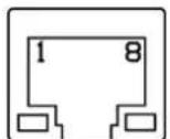
Fig. 14: Ethernet connector

ATTENTION! The Ethernet port is not POE (Power over Ethernet) compatible!
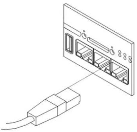
Ethernet cable plugs into the RJ45 connector labeled as ETH. (See Fig 27)
natural_image
Isometric line drawing of a device with two connectors, one connected to a wall-mounted panel (no text or symbols)Fig. 15: Ethernet Cable Connection
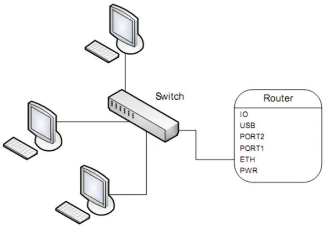
The Ethernet router connection:
flowchart
graph TD
    A["Switch"] --> B["Monitor 1"]
    A --> C["Monitor 2"]
    A --> D["Monitor 3"]
    A --> E["Monitor 4"]
    B --> F["Router"]
    C --> F
    D --> F
    E --> F
    style F fill:#f9f,stroke:#333
Fig. 16: Example of router connection
5.7 Ethernet Port
Port 1
Port One may be configured for Ethernet, serial communications (RS-232/485/422), or (I/O - CNT) based on the router model number. Port Two may be configured for serial communications (RS-232/485/422), or (I/O - CNT). Either port can be fitted with internal switch XC-SW.
Port 2
Port 2 may be configured for serial communications (RS-232/485/422), or (I/O - CNT). Either port can be fitted with internal switch XC-SW.
5.7.1 RS-232 Ports
The RS-232 port is configured as a Data Communication Equipment (DCE). A KD2 adapter cable can be used to convert the RJ-45 connector to a standard DB9 serial connector.
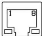
Fig. 17: RS232 port connector
| Pin no. | Signal mark | Description | Direction |
| 1 | RTS | Request To Send | Input |
| 2 | CTS | Clear To Send | Output |
| 3 | DTR | Data Terminal Ready | Input |
| 4 | DSR | Data Set Ready | Output |
| 5 | GND | Signal ground | |
| 6 | RXD | Receive Data | Output |
| 7 | CD | Carrier Detect | Output |
| 8 | TXD | Transmit Data | Input |
Table 14: RS232 connector Pinout
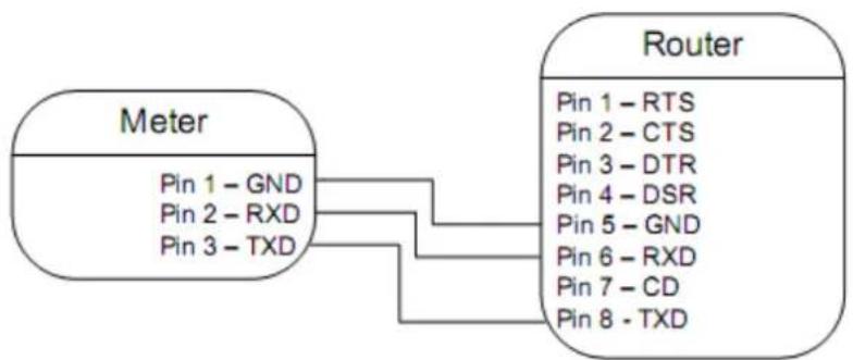
Example of connecting a meter to the router:
flowchart
graph LR
    A["Meter"] --> B["Router"]
    A -->|Pin 1 - GND| B
    A -->|Pin 2 - RXD| B
    A -->|Pin 3 - TXD| B
    B -->|Pin 1 - RTS| B
    B -->|Pin 2 - CTS| B
    B -->|Pin 3 - DTR| B
    B -->|Pin 4 - DSR| B
    B -->|Pin 5 - GND| B
    B -->|Pin 6 - RXD| B
    B -->|Pin 7 - CD| B
    B -->|Pin 8 - TXD| B
Fig. 18: Meter connection to router

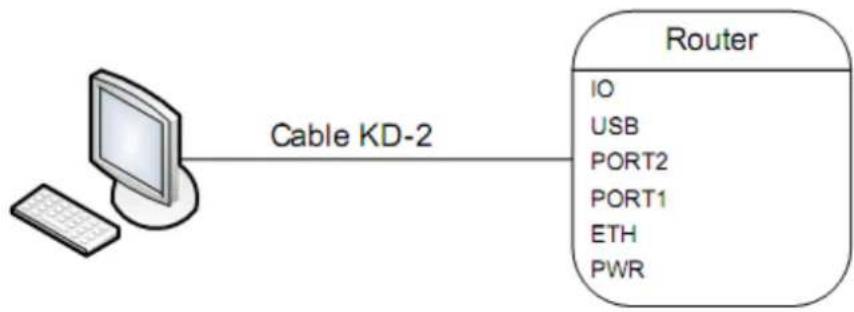
Example of a PC connection to the router:
flowchart
graph LR
    A["Cable KD-2"] --> B["Router"]
    B --> C["IO"]
    B --> D["USB"]
    B --> E["PORT2"]
    B --> F["PORT1"]
    B --> G["ETH"]
    B --> H["PWR"]
Fig. 19: PC connection to router
• Cable KD2 is connected to serial port PC (example COM1)

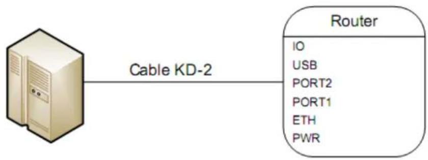
Example of the RS232 equipment connection to router (possibility to use all RS232 ports):
flowchart
graph LR
    A["Server"] -->|Cable KD-2| B["Router"]
    B --> C["IO"]
    B --> D["USB"]
    B --> E["PORT2"]
    B --> F["PORT1"]
    B --> G["ETH"]
    B --> H["PWR"]
Fig. 20: RS-232 equipment connection to router
5.7.2 RS-485/422 Ports
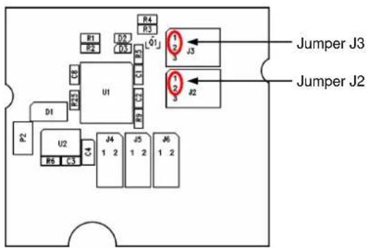
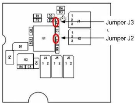
The RS-485/422 ports can be powered using the internal 3.3V supply or by connecting an external power supply to the port connector. External or internal power is selected by jumpers J2 and J3 on the RS-485 module daughter board. To use internal power, place jumpers J2 and J3 across pins 2 and 3. To select external power, jumpers J2 and J3 must be on pins 1 and 2.
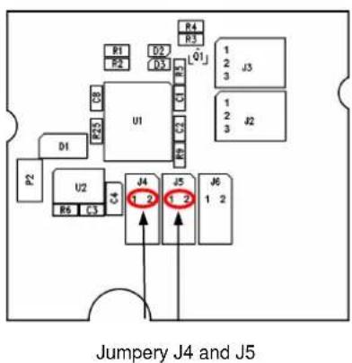
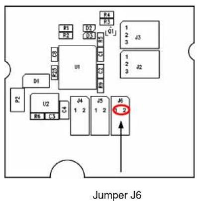
Interface behavior of module Expansion port RS485/RS422 can be made by wiring Jumpers J4, J5 and J6 on the RS-485 module select the mode of the port – either RS-485 or RS-422 mode. If RS485 is required, jumpers J4 and J5 must be connected and jumper J6 disconnected. If RS422 is required, jumpers J4 and J5 must be disconnected and jumper J6 connected.
Jumper placement can be seen in the picture below (RS-485 module is viewed from the top).

Internal power supply should only be used in the event that it is not possible to provide an external power supply.
text_image
R1 R2 D1 U1 R3 R4 R5 C3 J1 J2 J3 J4 J5 J6 J7 J8 J9 J10 J11 J12 J13 J14 J15 J16 J17 J18 J19 J20 J21 J22 J23 J24 J25 J26 J27 J28 J29 J30 J31 J32 J33 J34 J35 J36 J37 J38 J39 J40 J41 J42 J43 J44 J45 J46 J47 J48 J49 J50 J51 J52 J53 J54 J55 J56 J57 J58 J59 J60 J61 J62 J63 J64 J65 J66 J67 J68 J69 J70 J71 J72 J73 J74 J75 J76 J77 J78 J79 J80Fig. 21: Jumper Position for external supply
text_image
R1 R2 D1 U1 R4 R3 01 1 2 J3 3 Jumper J3 J Jumper J2 1 2 3 J2 1 2 J4 1 2 J5 1 2 J6 1 2 R6 C3Fig. 23: Jumper Position for internal supply
text_image
Jumper J4 and J5Fig. 22: Jumper Position for RS-485
text_image
Jumper J6Fig. 24: Jumper Position for RS-422
Connector Pinout
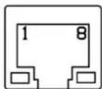
Fig. 25: RS485/422 connector
RS-485 Mode
| Pin number | Signal mark | Description | Data flow direction |
| 1 | GND | Signal and supply ground | |
| 2 | GND | Signal and supply ground | |
| 3 | TxRx- | RS485 B (-) | Input/Output |
| 4 | TxRx+ | RS485 A (+) | Input/Output |
| 5 | TxRx- | RS485 B (-) | Input/Output |
| 6 | TxRx+ | RS485 A (+) | Input/Output |
| 7 | +12 V EXT | External power supply | |
| 8 | +12 V EXT | External power supply |
Table 15: Connector Pinout in RS-485 Mode

ATTENTION! The power supply is selected on the module board using the jumpers.
Note: In RS-485 mode, pins 3 and 5 and pins 4 and 6 are internally shorted together. If galvanic separation is required, the converter must use an external power supply.
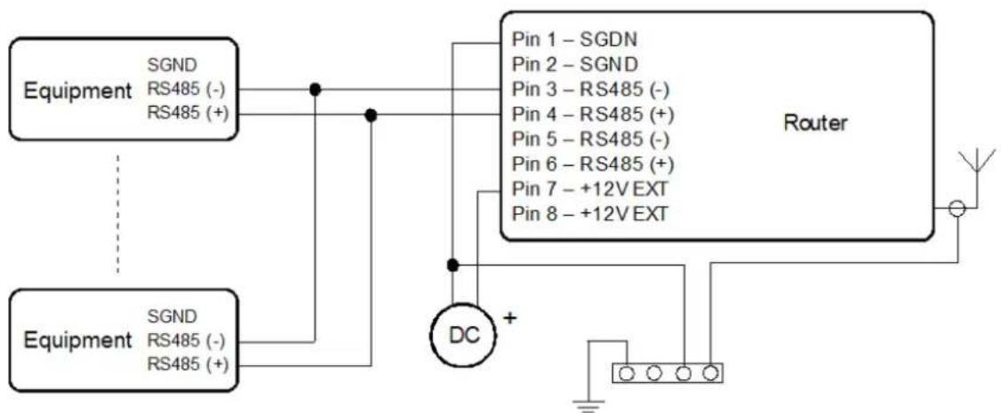
flowchart
graph TD
    A["Equipment"] -->|SGND RS485 (-) RS485 (+)| B["Router"]
    C["Equipment"] -->|SGND RS485 (-) RS485 (+)| B
    B --> D["DC +"]
    D --> E["Ground"]
    style B fill:#f9f,stroke:#333
    style A fill:#ccf,stroke:#333
    style C fill:#ccf,stroke:#333
    style B fill:#fff,stroke:#333
    style D fill:#fff,stroke:#333
    style E fill:#fff,stroke:#333
Fig. 26: Connection to the router with data cable length less than 10 m
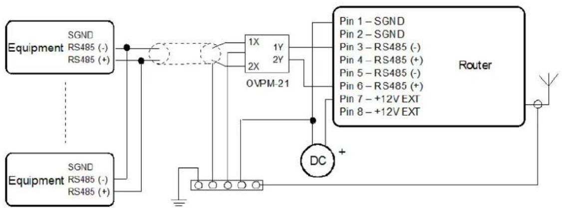
flowchart
graph TD
    A["Equipment"] -->|SGND RS485 (-) / RS485 (+)| B["1X 1Y 2X 0VPM-21"]
    C["Equipment"] -->|SGND RS485 (-) / RS485 (+)| B
    B --> D["Router"]
    E["DC"] --> D
    D --> F["Wire"]
    style A fill:#f9f,stroke:#333
    style C fill:#f9f,stroke:#333
    style B fill:#ccf,stroke:#333
    style D fill:#cff,stroke:#333
    style E fill:#cfc,stroke:#333
Fig. 27: Connection to the router with data cable length more than 10 m

With a RS-485 data cable more than 10m, it is necessary to use overvoltage protection on the router side!
RS-422 Mode
| Pin number | Signal mark | Description | Data flow direction |
| 1 | SGND | Signal and power supply ground | |
| 2 | SGND | Signal and power supply ground | |
| 3 | RxD- | Receive Data (-) | Output |
| 4 | RxD+ | Receive Data (+) | Output |
| 5 | TxD- | Transmit Data (-) | Input |
| 6 | TxD+ | Transmit Data (+) | Input |
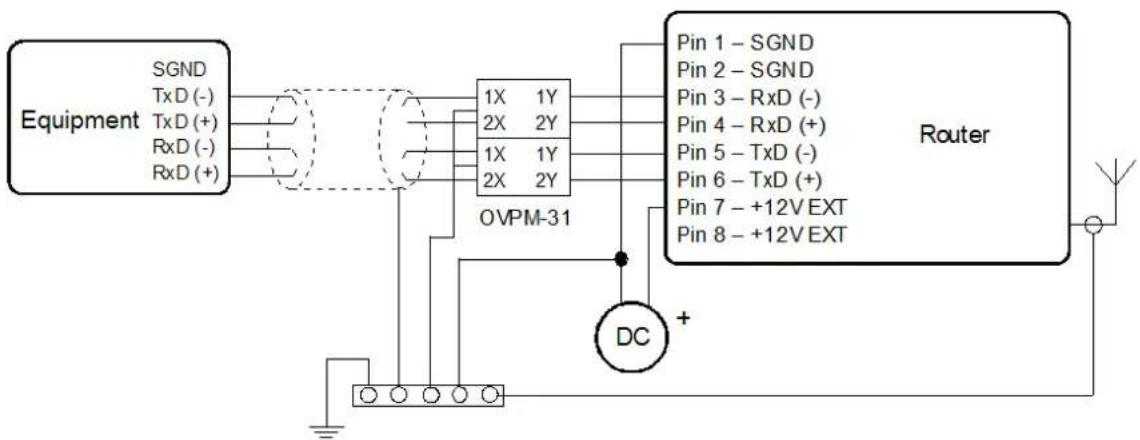
| 7 | +12V EXT | External power supply | |
| 8 | +12V EXT | External power supply |
Table 16: Connector Pinout in RS-422 Mode

ATTENTION! The power supply is selected on the module board using the jumpers.
If galvanic separation is required, the converter must use an external power supply.
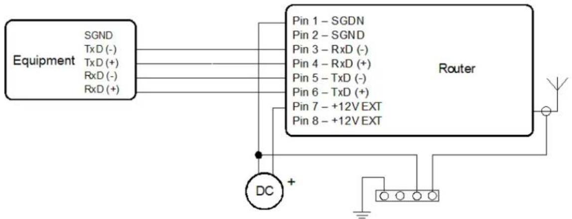
flowchart
graph TD
    A["Equipment"] -->|SGND, TxD (-), TxD (+), RxD (-), RxD (+)| B["Router"]
    B -->|Pin 1 - SGDN, Pin 2 - SGND, Pin 3 - RxD (-), Pin 4 - RxD (+), Pin 5 - TxD (-), Pin 6 - TxD (+), Pin 7 - +12V EXT, Pin 8 - +12V EXT| C["DC"]
    C --> D["+"]
    D --> E["Wireless"]
    B --> F["+"]
    F --> G["Ground"]
Fig. 28: Connection to the router with data cable length less than 10 m
flowchart
graph TD
    A["Equipment"] -->|SGND TxD (-)| B["OvPM-31"]
    A -->|TxD (+)| B
    A -->|RxD (-)| B
    A -->|RxD (+)| B
    B --> C["Pin 1 - SGND"]
    B --> D["Pin 2 - SGND"]
    B --> E["Pin 3 - RxD (-)"]
    B --> F["Pin 4 - RxD (+)"]
    B --> G["Pin 5 - TxD (-)"]
    B --> H["Pin 6 - TxD (+)"]
    B --> I["Pin 7 - +12V EXT"]
    B --> J["Pin 8 - +12V EXT"]
    B --> K["DC"]
    K --> L["Router"]
    L --> M["Wire"]
    style A fill:#f9f,stroke:#333
    style L fill:#ccf,stroke:#333
Fig. 29: Connection to the router with data cable length more than 10 m

With a RS422 data cable more than 10m long, it is necessary to use overvoltage protection on the router side!
5.7.3 I/O Port
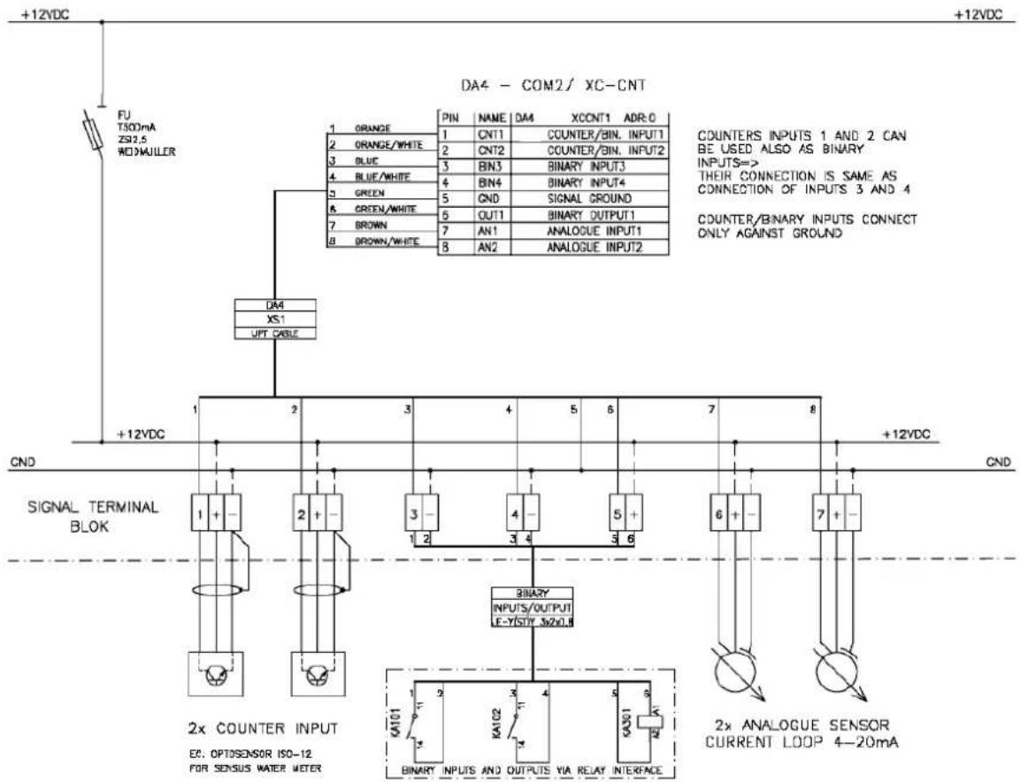
The I/O port user interface (CNT) is used to monitor analog and binary input signals and to control binary output signals. The interface has 6 inputs and 1 output. Two of the inputs can be configured as binary counter inputs or general purpose binary inputs. There are also 2 dedicated binary inputs, 2 analog current inputs, and 1 open-collector output. The options for the I/O port are configured by writing to register values on the I/O board using the MODBUS ASCII protocol.
The unit can periodically store the values of the inputs in memory. These log entries can be read by reading the individual memory locations. Up to 224 log entries may be stored. The logging interval can range from 1-65535 minutes.
5.7.3.1 Analog Inputs
The analog current inputs have a range from 0 to 20mA. The input impedance is 100 Ω and the ADC resolution is 12 bits. The averaging and sampling period may be adjusted by the user. Also, alarms thresholds may be set for each input.
The ADC value stored in memory is calculated using the following equation:
$$ \text { ADC Value } = ((1 2 b \text { value } + \text { addit. constant }) * \text { multiplic. constant }) / 1 0 0 0 $$
where the constants are programmed into memory by the user.
5.7.3.2 Binary Input
The binary input is sampled 8x per second with a sampling period of 1/64 seconds. The active level for each binary input may be set to either a logic 0 or logic 1. The inputs may be configured to generate an alarm when they become active. The input threshold for detecting a logic 1 can be set at either 8uA or 20mA using a jumper on the module board.
5.7.3.3 Counter Input
The counter inputs have a maximum input frequency of 100 Hz. The minimum input pulse width is 1ms. The counter input may be configured to generate an alarm when a threshold is reached.
5.7.3.4 Binary Output
The binary output is a transistor with an open collector output. In the inactive state (logic 0) the transistor is off. In the active state (log. 1), the transistor is on and will connect the output signal to ground (GND). The output transistor is rated at 100 mA and 30V.
The output may be configured to generate a pulse from 125 to 8000ms in length. It is also possible to configure the unit so that the output will become active when counter 1 (CNT1) reaches a threshold.
5.7.3.5 Selecting the Binary Input Current
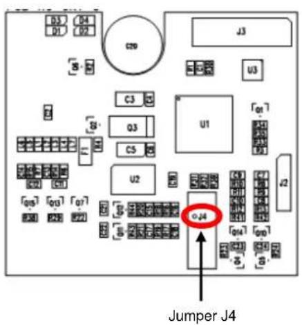
The input threshold for detecting a logic 1 can be set at either 8uA or 20mA using a jumper on the module board. When jumper J4 is shorted, the threshold current level is 20 mA. When jumper J4 is not shorted, the threshold current level is 8μA. A threshold current value of 20mA has a higher resistance to noise on the input but also dissipates more power.
text_image
D3 D4 D1 D2 C20 J3 U3 C3 B Q3 U1 C5 F1 U2 C2 C1 [05] [03] [07] P20 P23 P22 O-24 J2 Jumper J4Fig. 30: CNT I/O board
5.7.3.6 Input/Output Connector
Panel socket RJ45.
| Pin number | Signal mark | Description | Data flow direction |
| 1 | BIN1/CNT1 | Binary input/counter input | Input |
| 2 | BIN2/CNT2 | Binary input/counter input | Input |
| 3 | BIN3 | Binary input | Input |
| 4 | BIN4 | Binary input | Input |
| 5 | GND | Signal ground | |
| 6 | OUT1 | Binary output (open collector) | Output |
| 7 | AN1 | Analog Current input | Input |
| 8 | AN2 | Analog Current input | Input |
Table 17: Input/Output Connector Pinout
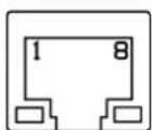
Fig. 31: CNT connector

Typical connection of the I/O port circuits:
flowchart
graph TD
    A["+12VDC"] --> B["FU T300mA ZS12.5 WDMJILLER"]
    B --> C["DA4"]
    C --> D["+12VDC"]
    D --> E["SIGNAL TERMINAL BLOK"]
    E --> F["2x COUNTER INPUT EC OPTOSensor ISO-12 FOR SENSUS WATER METER"]
    F --> G["8 2x ANALOGUE INPUTS AND OUTPUTS VIA RELAY INTERFACE"]
    G --> H["8 2x ANALOGUE INPUTS INPUT1"]
    G --> I["8 2x ANALOGUE INPUTS INPUT2"]
    H --> J["7 6 1BINARY INPUTS OUTPUT E-YISTY_3x2x0.8"]
    I --> K["7 6 1BINARY INPUTS OUTPUT E-YISTY_3x2x0.8"]
    J --> L["5 4 3 2 1 1 1 1 1 1 1 1 1"]
    K --> M["5 4 3 2 1 1 1 1 1 1 1 1"]
    L --> N["4 3 2 1 1 1 1 1 1 1 1 1 1"]
    M --> O["3 2 1 1 1 1 1 1 1 1 1 1"]
    N --> P["2 3 2 1 1 1 1 1 1 1 1 1"]
    O --> Q["2 3 2 1 1 1 1 1 1 1 1 1"]
    P --> R["2 x COUNTER INPUT EC OPTOSensor ISO-12 FOR SENSUS WATER METER"]
    Q --> S["2 x COUNTER INPUT EC OPTOSensor ISO-12 FOR SENSUS WATER METER"]
    R --> T["+12VDC"]
    S --> U["+12VDC"]
    T --> V["+12VDC"]
    U --> W["+12VDC"]
Fig. 32: Connection of the I/O Port circuitry
The I/O Port registers are read and written using MODBUS ASCII slave protocol over serial port 1. Using this protocol, it is possible to configure the I/O board, read the input status, and control the output. The I/O port communicates at 9600 baud, 8 bits, no parity, and 1 stop bit (8N1).
Address space
| Address | Access | Description |
| 0x0000 | R/- | Firmware type |
| 0x0001 | R/- | Upper 16 bits of firmware version |
| 0x0002 | R/- | Lower 16 bits of firmware version |
| 0x0003 | R/- | Supports firmware characteristicsbit 0 – Analog input AN1bit 1 – Analog input AN2bit 2 – Counter input CNT1bit 3 – Counter input CNT2bit 4 – Binary input BIN1bit 5 – Binary input BIN2bit 6 – Binary input BIN3bit 7 – Binary input BIN4• bit 8 – Binary output OUT1• bit 9 – Automatic feeder control• bit 10 – Full duplex counter CNT1/CNT2 |
| 0x0004 | R/- | Maximum log entries in buffer |
| 0x0005 | R/W | Marker of log launching and alarms work |
| 0x0006 | R/W | Upper 16 bits of current time in seconds, numbered from 1/1/1970 |
| 0x0007 | R/W | Lower 16 bits of current time in seconds, numbered from 1/1/1970 |
| 0x0008 | R/W | Upper 16 bits of log entry timestamp |
| 0x0009 | R/W | Lower 16 bits of log entry timestamp |
| 0x000A | R/- | Alarm actual status |
| 0x0100 | R/- | Binary input status |
| 0x0200 | R/W | Binary output status |
| 0x0300 | R/- | Recalculate value of analog input AN1 (with sign) |
| 0x0400 | R/- | Recalculate value of analog input AN2 (with sign) |
| 0x0500 | R/W | Upper 16 bits of counter CNT1 value |
| 0x0501 | R/W | Lower 16 bits of counter CNT1 value |
| 0x0502 | R/- | Prompt frequency CNT1 |
| 0x0503 | R/- | Average frequency CNT1 |
| 0x0504 | R/- | Minimum frequency CNT1 |
| 0x0505 | R/- | Maximum frequency CNT1 |
| 0x0601 | R/W | Upper 16 bits of counter CNT2 value |
| 0x0601 | R/W | Lower 16 bits of counter CNT2 value |
| 0x0602 | R/- | Prompt frequency CNT2 |
| 0x0603 | R/- | Average frequency CNT2 |
| 0x0604 | R/- | Minimum frequency CNT2 |
| 0x0605 | R/- | Maximum frequency CNT2 |
| 0x0F00 | R/- | 0x0000 always |
| 0x0F01 | R/- | 0x0000 always |
| 0x0F02 | R/- | Upper 16 bits of seconds, number from 1.1.1970 |
| 0x0F03 | R/- | Lower 16 bits of seconds, number from 1.1.1970 |
| 0x0F04 | R/- | Alarms status• bit 0 – active level on input BIN1• bit 1 – active level on input BIN2• bit 2 – active level on input BIN3• bit 3 – active level on input BIN4• bit 4 – analog input lower limit overrun AN1bit 5 – analog input upper limit overrun AN1bit 6 – analog input lower limit overrun AN2bit 7 – analog input upper limit overrun AN2bit 8 – limit frequency overrun CNT1bit 9 – limit frequency overrun CNT2 |
| 0x0F05 | R/- | Binary inputs statusbit 0 – level on input BIN1bit 1 – level on input BIN2bit 2 – level on input BIN3bit 3 – level on input BIN4bit 6 – level on output BOUT1 |
| 0x0F06 | R/- | Recalculate AN1 value (with sign) |
| 0x0F07 | R/- | Recalculate AN2 value (with sign) |
| 0x0F08 | R/- | Upper 16 bits CNT1 |
| 0x0F09 | R/- | Lower 16 bits CNT1 |
| 0x0F0A | R/- | Prompt frequency CNT1 |
| 0x0F0B | R/- | Average frequency CNT1 |
| 0x0F0C | R/- | Minimal frequency CNT1 |
| 0x0F0D | R/- | Maximal frequency CNT1 |
| 0x0F0E | R/- | Upper 16 bits of counter CNT2 value |
| 0x0F0F | R/- | Lower 16 bits of counter CNT2 value |
| 0x0F10 | R/- | Prompt frequency CNT2 |
| 0x0F11 | R/- | Average frequency CNT2 |
| 0x0F12 | R/- | Minimal frequency CNT2 |
| 0x0F13 | R/- | Maximal frequency CNT2 |
| 0x1000 | R/- | 1. log – upper 16 bits of log number |
| 0x1001 | R/- | 1. log – lower 16 bits of log number |
| 0x1002 | R/- | 1. log – upper 16 bits of time stamps |
| 0x1003 | R/- | 1. log – lower 16 bits of time stamps |
| 0x1004 | R/- | 1. log – alarms status |
| 0x1005 | R/- | 1. log – binary inputs status |
| 0x1006 | R/- | 1. log – recalculate value AN1 (with sign) |
| 0x1007 | R/- | 1. log – recalculate value AN2 (with sign) |
| 0x1008 | R/- | 1. log – upper 16 bits CNT1 |
| 0x1009 | R/- | 1. log – lower 16 bits CNT1 |
| 0x100A | R/- | 1. log – prompt frequency CNT1 |
| 0x100B | R/- | 1. log – average frequency CNT1 |
| 0x100C | R/- | 1. log – minimal frequency CNT1 |
| 0x100D | R/- | 1. log – maximal frequency CNT1 |
| 0x100E | R/- | 1. log – upper 16 bits of counter CNT2 value |
| 0x100F | R/- | 1. log - lower 16 bits of counter CNT2 value |
| 0x1010 | R/- | 1. log - prompt frequency CNT2 |
| 0x1011 | R/- | 1. log - average frequency CNT2 |
| 0x1012 | R/- | 1. log - minimal frequency CNT2 |
| 0x1013 | R/- | 1. log - maximal frequency CNT2 |
| 0x1100 | R/- | 2. log |
| 0x1200 | R/- | 3. log |
| ... | R/- | ... |
| 0xEF00 | R/- | 224. log |
| 0xF000 | -/W | Samples stores period [min] |
| 0xF001 | -/W | Allowed:bit 0 - active level on input BIN1bit 1 - active level on input BIN2bit 2 - active level on input BIN3bit 3 - active level on input BIN4bit 4 - analog input AN1 lower limit overrunbit 5 - analog input AN1 upper limit overrunbit 6 - analog input AN2 lower limit overrunbit 7 - analog input AN2 upper limit overrunbit 8 - limit frequency CNT1 overrunbit 9 - limit frequency CNT2 overrun |
| 0xF100 | -/W | Binary inputs negative logicalbit 0 - input BIN1bit 1 - input BIN2bit 2 - input BIN3bit 3 - input BIN4 |
| 0xF200 | -/W | Binary outputs normal levelbit 0 - output OUT1 |
| 0xF201 | -/W | Feeder - impulse number on input BIN1/CNT1 |
| 0xF202 | -/W | Feeder - impulse length on output OUT1 [1/8 sec] |
| 0xF300 | -/W | AN1 - samples period [sec] |
| 0xF301 | -/W | AN1 - multiplicative constant (with sign) |
| 0xF302 | -/W | AN1 - additive constant (with sign) |
| 0xF303 | -/W | AN1 - hysteresis value (with sign) |
| 0xF304 | -/W | AN1 - lower limit (with sign) |
| 0xF305 | -/W | AN1 – upper limit (with sign) |
| 0xF306 | -/W | bits 7-3:AN1 – metering circuit switch time0 → 1/64 sec1 → 2/64 sec...30 → 31/64 secbits 2-0:AN1 – samples number for average0 → 1 sample1 → 2 samples2 → 4 samples4 → 8 samples5 → 16 samples |
| 0xF400 | -/W | AN2 – samples period [sec] |
| 0xF401 | -/W | AN2 – multiplicative constant (with sign) |
| 0xF402 | -/W | AN2 – additive constant (with sign) |
| 0xF403 | -/W | AN2 – hysteresis value (with sign) |
| 0xF404 | -/W | AN2 – lower limit (with sign) |
| 0xF405 | -/W | AN2 – upper limit (with sign) |
| 0xF406 | -/W | bits 7-3:AN2 – metering circuit switch time0 → 1/64 sec1 → 2/64 sec...30 → 31/64 secbits 2-0:AN2 – samples number for average0 → 1 sample1 → 2 samples2 → 4 samples4 → 8 samples5 → 16 samples |
| 0xF500 | -/W | CNT1 – multiplicative constant |
| 0xF501 | -/W | CNT1 – upper limit |
| 0xF502 | -/W | CNT1 – time of limit overrun [sec] |
| 0xF503 | -/W | CNT1 – time for metering reset [sec] |
| 0xF600 | -/W | CNT2 – multiplicative constant |
| 0xF601 | -/W | CNT2 – upper limit |
| 0xF602 | -/W | CNT2 – time of limit overrun [sec] |
| 0xF603 | -/W | CNT2 – time for metering reset [sec] |
| 0xFFFF | -/W | Switch main supply off on set time [min] |
Table 18: MODBUS Input/Output Address space
5.8 USB Port
PANEL SOCKET USB-A
| Pin number | Signal mark | Description | Data flow direction |
| 1 | +5V | Positive pole of 5V DC supply voltage | |
| 2 | USB data - | USB data signal – negative pole | Input/Output |
| 3 | USB data + | USB data signal – positive pole | Input/Output |
| 4 | GND | Negative pole of DC supply voltage |
Table 19: Connection of USB connector

Fig. 33: USB connector
Example of connecting devices with a serial interface to the USB router:
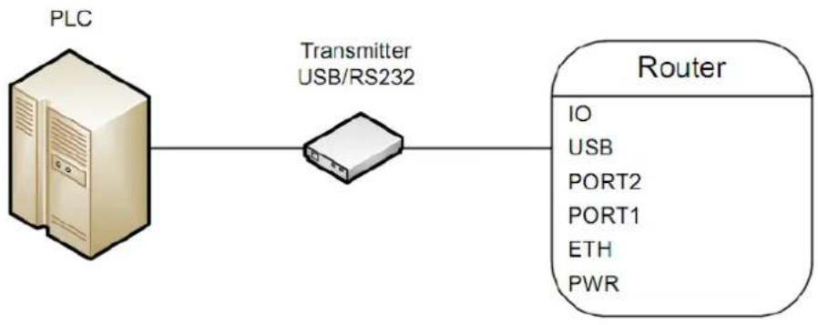
flowchart
graph LR
    A["PLC"] --> B["Transmitter USB/RS232"]
    B --> C["Router"]
    C --> D["IO"]
    C --> E["USB"]
    C --> F["PORT2"]
    C --> G["PORT1"]
    C --> H["ETH"]
    C --> I["PWR"]
Fig. 34: Connecting a PLC to the router
Connecting a USB flash drive to the USB router:
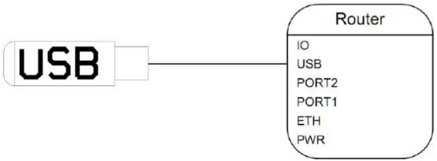
flowchart
graph LR
    A["USB"] --> B["Router"]
    B --> C["IO"]
    B --> D["USB"]
    B --> E["PORT2"]
    B --> F["PORT1"]
    B --> G["ETH"]
    B --> H["PWR"]
Fig. 35: Connecting USB memory stick to the router
5.9 I/O Port
| 3-PIN PANEL SOCKET | |||
| Pin no. | Signal mark | Description | Data flow direction |
| 1 | BIN0 | Binary input | Input |
| 2 | GND | Signal ground | |
| 3 | OUT0 | Binary output | Output |
Table 20: I/O port Connection

Fig. 36: I/O connection
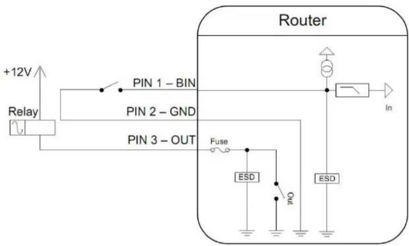
The user interface I/O is for the processing of binary input signals and for control (settings) of binary output signals. Binary output is not switched to ground in the default configuration.
The maximum load for the binary output is 30V / 100mA. The constant current supplied by the binary input is 3 mA.
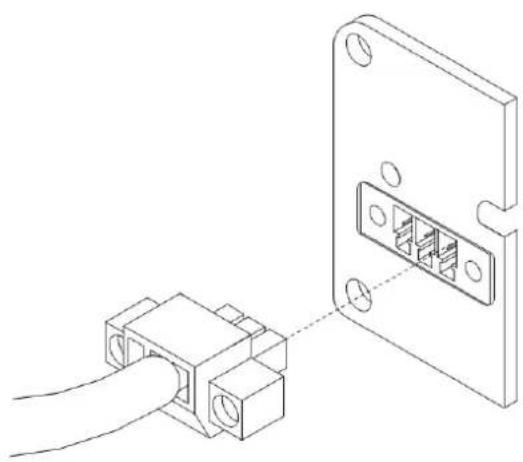
Connect the cable's I/O connector to the router's I/O port and tighten locking screws. (See Fig. 35)
natural_image
Technical line drawing showing a connector inserted into a device housing (no text or symbols present)Fig. 37: Connection I/O cable
Circuit example of a binary input or output connected to the router:
flowchart
graph TD
    A["Router"] -->|+12V| B["Relay"]
    B --> C["PIN 1 - BIN"]
    B --> D["PIN 2 - GND"]
    B --> E["PIN 3 - OUT"]
    C --> F["Fuse"]
    D --> G["ESD"]
    E --> H["Out"]
    F --> I["ESD"]
    G --> J["In"]
Fig. 38: Connection of binary input and output of router
6.0 Resetting or Rebooting the Router
It is important to distinguish between resetting and rebooting the router.
| Action | Router behavior | Actions |
| Reboot | Turn off and then turn on router | Disconnect and connect the power. |
| Press therebootbutton in the Web configuration. | ||
| Reset | Restore the factory default configuration and reboot the router. | Press RST button. |
Table 21: Ways to reset or restart the router
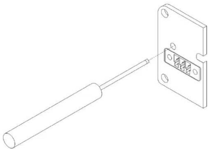
After the green LED starts to blink you may restore the router's initial settings by pressing button RST on front panel. The router will restore its factory default configuration and reboot (The green LED will be on).
To reset, use a narrow screwdriver. (See Fig. 37)
natural_image
Technical line drawing of a mechanical component with a cylindrical rod inserted into a rectangular housing (no text or symbols)Fig. 39: Router reset

We recommend backing up your router configuration before resetting. (See the separate configuration manual). A router reset will erase your configuration and return the router to its default settings.
7.0 First Use
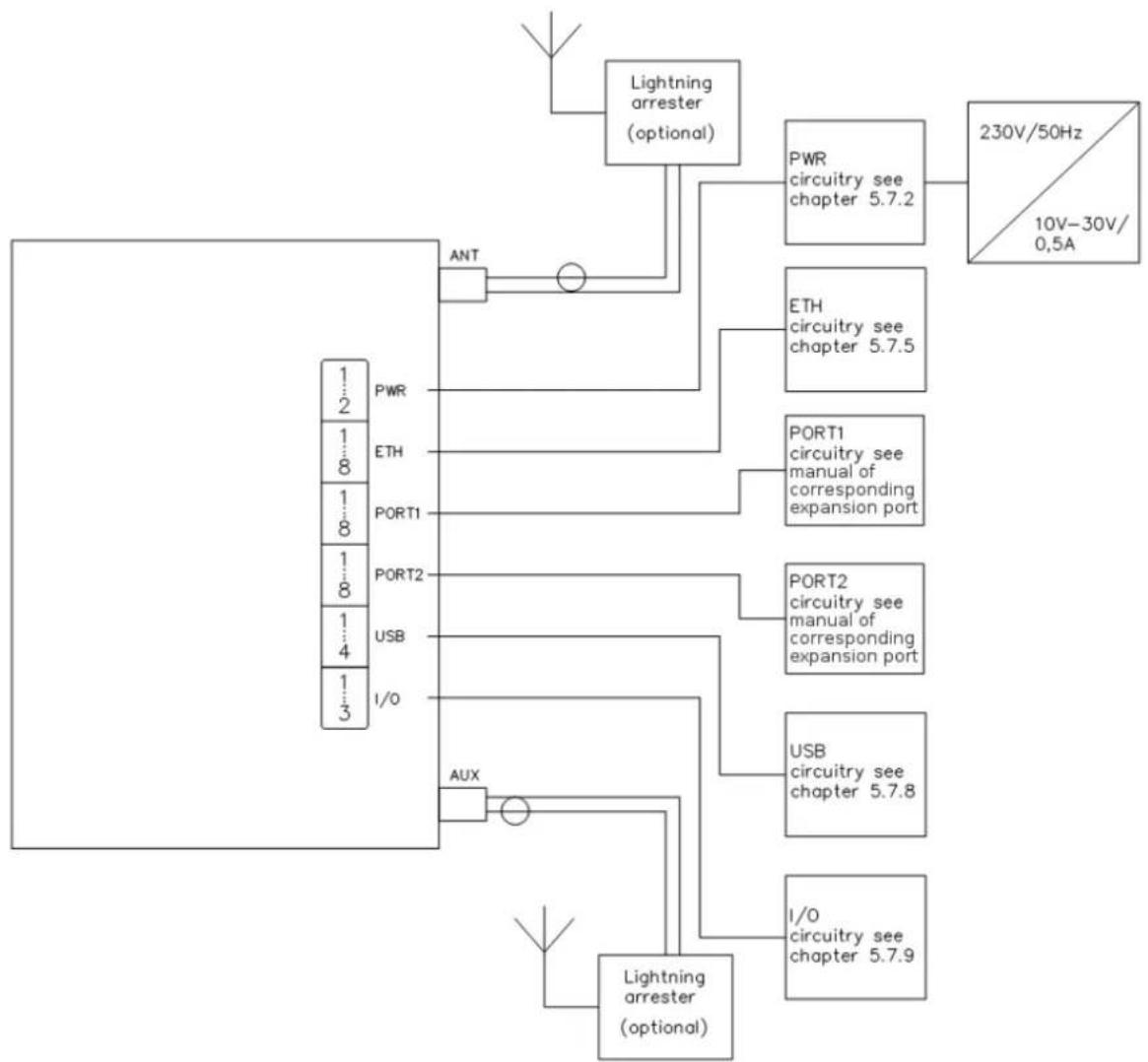
Before you can set up the router you will need to make all of the necessary connections. The router cannot operate without a connected antenna, SIM card (for UMTS networks), and a power supply.
Operating the router without an antenna can damage the router.
flowchart
graph TD
    A["Ant"] --> B["Lightning arrester (optional)"]
    B --> C["PWR circuitry see chapter 5.7.2"]
    B --> D["ETH circuitry see chapter 5.7.5"]
    B --> E["PORT1 circuitry see manual of corresponding expansion port"]
    B --> F["PORT2 circuitry see manual of corresponding expansion port"]
    B --> G["USB circuitry see chapter 5.7.8"]
    B --> H["I/O circuitry see chapter 5.7.9"]
    B --> I["AUX"]
    I --> J["Lightning arrester (optional)"]
    C --> K["230V/50Hz / 10V-30V/0.5A"]
    D --> K
    E --> K
    F --> K
    G --> K
    H --> K
    I --> K
    J --> K
Fig. 40: Router connections
7.1 Starting the router
Connect power to the router. In the default setting the router will start to login automatically to the preset APN. The Ethernet port DHCP server will assign device addresses. The behavior of the router can be modified by means of the Web or Telnet interface, as described in the configuration manual.
The power consumption during receiving is 2W. The peak power consumption during data sending is 5.5 W. For correct operation the power source must be able to supply a peak current of 600mA.
7.2 Configuring the router

Attention! The cellular carrier and network must be configured in the router prior to use. For UMTS and LTE networks, the router will not operate without a SIM card. The SIM card must be provisioned for the necessary network (LTE/HSPA+/UMTS/EDGE/GPRS). For 3G CDMA networks, the router is provisioned over-the-air. Refer to the Configuration manual for details on configuring the router based on the cellular carrier and network.
Configuration over Web browser
Monitoring of the status, configuration and administration of the router can be done via the Web interface. The default IP address of the router is 192.168.1.1. The username is "root". The password is "root".
A detailed description of configuring the router via the Web interface can be found in the configuration manual
Configuration over Telnet
Monitoring of status, configuration and administration of the router can be performed by means of the Telnet interface. The default IP address of the router is 192.168.1.1. The username is "root". The password is "root".
A detailed description of configuring the router via Telnet can be found in the configuration manual.
7.3 Technical Parameters
| SPECTRE Cellular Router | ||
| Complies with standards | EN 301 511, v9.0.2,EN 301 908-1&2, v3.2.1,ETSI EN 301 489-1 V1.8.1,EN 60950-1:06 ed.2 + A11:09 + A1:10UL CLASS I, DIV 2, GROUPS A, B, C, AND D | |
| Temperature range | Function | -30°C to +60°C |
| Storage | -40°C to +85°C | |
| Protection | Freely | IP20 |
| In switch board | IP56 | |
| Supply voltage | 10 to 30 V DC Class 2 Power Supply Only | |
| Consumption | Receive Mode | 2.3 W |
| Transmit: GPRS | to 3.5 W (GPRS transmission) | |
| Transmit: UMTS/HSDPA/EVDC | to 5.5 W (UMTS/HSDPA/LTE transmission) | |
| Dimensions | 42x76x113 mm (DIN 35mm) | |
| Weight | 280 g | |
| Antenna connector | SMA– 50 Ohm | |
| User interface | ETH | Ethernet (10/100 Mbit/s) |
| USB | USB 2.0 type A host | |
| PORT 1 | Model Dependent | |
| PORT 2 | Model Dependent | |
Table 22: General Specifications
| Cellular Mode | |
| LTE parameters | Bit rate 100 Mbps (DL) / 50 Mbps (UL)3GPP rel. 8 standardSupported bandwidth: 5 Mhz, 10 Mhz, 20 Mhz |
| HSPA+ parameters | bit rate 21.1 Mbps/5,76 Mbps3GPP rel. 7 standardUE CAT. 1 to 6, 8, 10, 12, 14Data compress 3GPP |
| UMTS parameters | PS bitrate - 384/384 kbpsCS bitrate - 64/64 kbpsW-CDMA FDD standard |
| GPRS parameters | bit rate 236 kbps/236kbpsGPRS multislot class 10, CS 1 to 4EGPRS multislot class 10, CS 1 to 4,MCS 1 to 9 |
| Transmit power | UMTS/HSUPA/HSDPA/HSPA+ - (20dBm)EGSM900/GSM850 - Class 4 (33dBm)GSM1800/1900 - Class 1 (30dBm) |
| Supported channels | GSM/GPRS/EDGE850Mhz, 900Mhz, 1800Mhz, 1900MhzUMTS/HSDPA/HSUPA/HSPA+800Mhz, 850Mhz, 900Mhz,1900Mhz, 2100MhzLTE: 800/900/1800/2100/2600 Mhz |
Table 23: Cellular Module Specifications
| 32b ARM microprocessor | |
| Memory | 512 Mb DDR SDRAM128 Mb FLASH1 Mb MRAM |
| Interface | Serial interface RS232Ethernet interface 10/100Mbit/sUSB 2.0 interface |
Table 24: Processor Specifications
| Port IO | ||
| Input/Output | Binary input | reed contact with trigger level 1.3 up to 1.4 V |
| Binary output | 120 mA/max. 30 V | |
Table 25: I/O Port Specifications
| WIFI Specifications | |||
| Power supply | Internal | +3,3V | |
| Environment | Operating temperature | -15 .. +65 C | |
| Storage temperature | -20 .. +85 C | ||
| Standards | Emission | EN 55022/B | |
| Immunity | ETS 300 342 | ||
| Safety | EN 60950 | ||
| Isolation | EN 60747 | ||
| WIFI specifications (802.11 b/g/n) | RX Sensitivity | 11b, 11Mbps | -85 dBm |
| 11g, 54Mbps | -70 dBm | ||
| (HT20) 11n, MSC7 | -66 dBm | ||
| (HT20) 11n, MSC7 | -62 dBm | ||
| TX Output power | 11b, 11Mbps | 19 dBm | |
| 11g, 54Mbps | 16 dBm | ||
| 802.11n (HT20) | 15 dBm | ||
| 802.11n (HT20) | 15 dBm | ||
| Internal Antenna Impedance | 50 Ω | ||
| Frequency band | 2,4GHz | ||
Table 26: WiFi Specifications
8.0 Troubleshooting
8.1 FAQ
Q. I have NAT enabled. My equipment is not connecting to the network
- The device's gateway has to be configured as the router.
Q. The router resets itself and the Ethernet connection fails.
- The router will not function without an antenna. Keep the antenna as far as possible from the power supply.
Q. I can't access the Web server over NAT.
- The remote http access of the router has to be disabled, the default server address has to be your web server and the gateway of the web server has to be the IP of the router.
Q. PPP connection fails. (DAT LED off)
- Check signal power. If signal power is weak you will need a better antenna. If the neighboring cells have a similar signal strength, you will need to use a directional antenna. For proper operation, the signal levels have to be in the range from -50dBm to -90dBm. It is necessary to set ping, which will check the connection and, in the case of failed ping, restart the connection.
Q. PPP connection cannot be established. (DAT LED off)
- Recheck GPRS settings - APN, name, password and IP address.
- Try to enter PIN – verify if the SIM card has the PIN code set.
• In a private APN, switch the DNS server send off. - Switch the system log on and observe where the error occurs.
Q. FTP doesn't function.
- Router doesn't support active FTP mode. It supports passive mode only.
Q. RS-232 doesn't function.
- Verify that the router supports RS-232 communications. Also verify the RS-232 communication settings. To do so, open the router's configuration menu via the web browser, select the appropriate expansion port and verify the settings in the configuration menu.
Q. L2TP or IPSec isn't establishing.
Check the system log for error messages.
Q. I switched the router to offline mode by SMS message, but the router is in online mode after restart.
- SMS messages do not change the router configuration. They remain in effect only until the router is restarted.
9.0 Customer Support
Up to date information product information is on the website:
http://www.bb-elec.com/
For Technical Support: Call 815-433-5100
Maintenance:
Handle the SIM card carefully. Do not bend, scratch or expose the card to static electricity.
Do not clean the router with harsh chemicals, solvents or abrasive cleaners.
B&B Electronics hereby declares that the router described in this user's guide fits all basic demands of directive 1999/5/EC (R&TTE).
Router fits values of coefficient SAR defined by association ICNIRP and values of "About protection of health before non-ionized radiation".

Declaration of consistency was issued and may be viewed on the accompanying CD or acquired from the manufacturer.