VESR921 - Server B&B Electronics - Free user manual and instructions
Find the device manual for free VESR921 B&B Electronics in PDF.


User questions about VESR921 B&B Electronics
0 question about this device. Answer the ones you know or ask your own.
Ask a new question about this device
Download the instructions for your Server in PDF format for free! Find your manual VESR921 - B&B Electronics and take your electronic device back in hand. On this page are published all the documents necessary for the use of your device. VESR921 by B&B Electronics.
USER MANUAL VESR921 B&B Electronics
natural_image
Blue and green electronic device labeled 'BIS ELECTRONICS' with ports and connectors (no readable text beyond branding)B+B SMARTWORX®
B+B SMARTWORX®
International Headquarters
B+B SmartWorx.
707 Dayton Road
Ottawa, IL 61350 USA
Phone (815) 433-5100 -- General Fax (815) 433-5105
Website: www.bb-smartworx.com
support@bb-smartworx.com
European Headquarters
B+B SmartWorx
Westlink Commercial Park
Oranmore, Co. Galway, Ireland
Phone +353 91-792444 -- Fax +353 91-792445
Document: VESR9xx _3615m
CONTENTS
Introduction 6
ABOUT VESR9XX SERIAL SERVERS 6
VESR9XX SERIAL SERVER MODEL NUMBERING 7
LIST OF VESR9XX SERIAL SERVER MODELS 8
VESR9XX SERIAL SERVER FEATURES 10
VLINX MANAGER CONFIGURATION SOFTWARE 10
VESR9XX SERIAL SERVER HARDWARE 11
PACKAGE CHECKLIST 11
VESR9XX SERIAL SERVER ENCLOSURES AND MOUNTING.... 11
LED INDICATORS(VESR90X) 12
LINK LED 12
READY LED 12
SERIAL PORT LEDS....12
LED INDICATORS (VESR92X) 12
MODE SWITCH 13
ETHERNET CONNECTOR 14
FIBER OPTIC CONNECTORS 15
SERIAL PORT CONNECTORS 15
POWER CONNECTOR 16
MOUNTING HARDWARE 17
SERIAL SERVER SETUP AND CONNECTIONS 17
CONNECTING THE POWER SUPPLY 17
CONNECTING VESR9XX SERIAL SERVERS TO SERIAL DEVICES 18
CONNECTING THE VESR901-X 19
CONNECTING THE VESR902T-X....19
CONNECTING THE VESR902D-X 20
CONNECTING VESR9XX SERIAL SERVERS TO A NETWORK 21
NETWORK CONNECTION (10BASET/100BASETX) 21
FIBER OPTIC CONNECTION.... 21
VESR9XX SERIAL SERVER CONFIGURATION CONNECTIONS 22
CONFIGURING THE VESR9XX SERIAL SERVER VIA THE NETWORK
CONNECTION 22
CONFIGURING THE VESR9XX SERIAL SERVER VIA THE SERIAL PORT
(CONSOLE MODE) 23
VESR9XX SERIAL SERVER OPERATIONAL CONNECTIONS 24
USING VESR9XX SERIAL SERVERS IN DIRECT IP MODE 25
USING VESR9XX SERIAL SERVERS IN VIRTUAL COM PORT MODE......25
USING VESR9XX SERIAL SERVERS IN PAIRED MODE.... 26
INITIATING A HARDWARE RESET ON THE SERIAL SERVER 27
RELOADING FACTORY DEFAULTS 27
Description of Serial Server Properties.... 28
BAUD RATE 28
CHARACTER COUNT 28
CONFIGURATION FILES 28
DATA/PARITY/STOP 28
DEFAULT GATEWAY 29
DELIMITER 1, DELIMITER 2 AND DELIMITER REMOVAL 29
DELIMITER 1 29
DELIMITER 2 29
DELIMITER REMOVAL 29
HOW DELIMITERS WORK 30
DHCP 30
FIRMWARE VERSION 31
FLOW CONTROL 31
FORCED TRANSMIT 31
HARDWARE VERSION 31
INTER-CHARACTER TIMEOUT 31
IP ADDRESS 32
LINK STATUS 34
MAC ADDRESS 34
MODEL 35
NETWORK PROTOCOLS 35
NETWORK WATCHDOG 35
PAIRED MODE 35
PASSWORD 36
SERIAL INTERFACE MODES 36
SERIAL SERVER NAME 37
SERVER SERIAL PORT NUMBER 37
SERIAL WATCHDOG 37
SUBNET MASK 37
TCP (TRANSMISSION CONTROL PROTOCOL) 38
UDP (USER DATAGRAM PROTOCOL) 38
VCOM (VIRTUAL COM PORT) 39
UPGRADING THE SERIAL SERVER FIRMWARE 39
DOWNLOADING FIRMWARE FILES 40
UPLOADING THE FIRMWARE TO THE SERIAL SERVER 40
Diagnostics 42
TESTING A SERIAL SERVER CONNECTION 42
TESTING A VIRTUAL COM PORT 43
Appendix A: Default Server Settings.... 45
APPENDIX B: PRODUCT SPECIFICATIONS 46
GENERAL SPECIFICATIONS 46
CONTROLS, INDICATORS AND CONNECTOR SPECIFICATIONS...... 48
SERIAL INTERFACE SPECIFICATIONS 49
NETWORK SPECIFICATIONS 50
Appendix C: Dimensional Diagrams.... 51
APPENDIX D: CONNECTOR PINOUTS 55
VESR901 & VESR921 SERIES 55
VESR902D SERIES 57
VESR902T & VESR922T SERIES.... 58
STANDARD ETHERNET CABLE RJ-45 PIN-OUT 59
B&B SMARTWORX TECHNICAL SUPPORT....60
INTRODUCTION
Thank you for purchasing a VESR9xx Serial Server product! This product has been manufactured to the highest standards of quality and performance to ensure your complete satisfaction.
natural_image
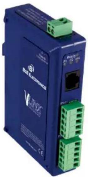
Blue BOS ELECTRONICS device with green connectors and ports (no readable text or symbols beyond branding)A VESR902T Serial Server
ABOUT VESR9XX SERIAL SERVERS
VESR9xx Serial Servers connect serial devices (RS-232, RS-422 or RS-485) to Ethernet networks, allowing the serial device to become a node on the network. The serial ports can be accessed over a LAN/WAN using Direct IP Mode, Virtual COM Port, or Paired Mode connections. VESR9xx Serial Servers feature 10BaseT or 100BaseTX copper network media and several fiber optic media options, depending on the model. VESR92x serial servers feature an additional copper Ethernet pass-through port. VESR9xx Serial Servers are built for use in industrial environments, featuring an IP30 approved slim line DIN rail mountable case. They operate from a range of DC power supply voltages and feature pluggable terminal block power connectors.
VESR9XX SERIAL SERVER MODEL NUMBERING
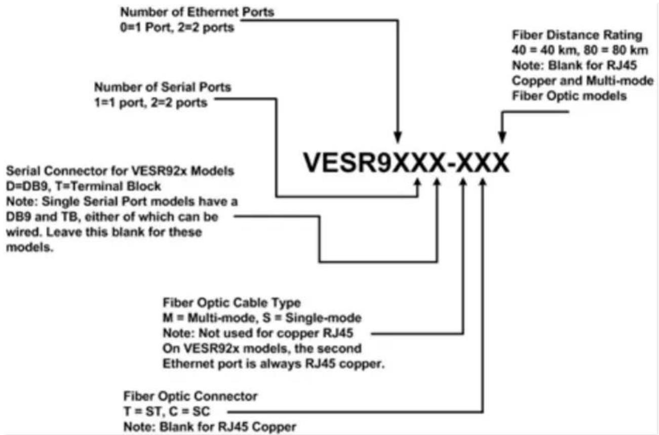
VESR9xx Serial Server are a growing family of products. Models are available with one or two serial connections and one or two Ethernet connections. Network connection options include 10BaseT/100BaseTX copper or several different fiber optic options (on models with a pass-through port, the pass-through port is copper). The following diagram shows the model numbering scheme:
flowchart
graph TD
    A["Number of Ethernet Ports\n0=1 Port, 2=2 ports"] --> B["VESR9XXX-XXX"]
    C["Number of Serial Ports\n1=1 port, 2=2 ports"] --> B
    D["Serial Connector for VESR92x Models\nD=DB9, T=Terminal Block\nNote: Single Serial Port models have a DB9 and TB, either of which can be wired. Leave this blank for these models."] --> B
    E["Fiber Optic Cable Type\nM = Multi-mode, S = Single-mode\nNote: Not used for copper RJ45\nOn VESR92x models, the second Ethernet port is always RJ45 copper."] --> B
    F["Fiber Optic Connector\nT = ST, C = SC\nNote: Blank for RJ45 Copper"] --> B
    G["Fiber Distance Rating\n40 = 40 km, 80 = 80 km\nNote: Blank for RJ45 Copper and Multi-mode\nFiber Optic models"] --> B
The following table lists the various VESR9xx Serial Server models available.
| Model Number | Features |
| VESR901 | Vlinx, 1PORT, DB9, ESS, DIN, CU ETHERNET |
| VESR901-SC40 | Vlinx, 1PORT, DB9, ESS, DIN, FIBER, SC, 40KM |
| VESR901-SC80 | Vlinx, 1PORT, DB9, ESS, DIN, FIBER, SC, 80KM |
| VESR901-ST | Vlinx, 1PORT, DB9, ESS, DIN, FIBER, ST |
| VESR901-ST40 | Vlinx, 1PORT, DB9, ESS, DIN, FIBER, ST, 40KM |
| VESR901-ST80 | Vlinx, 1PORT, DB9, ESS, DIN, FIBER, ST, 80KM |
| VESR902D | Vlinx, 2PORT, DB9, ESS, DIN, CU ETHERNET |
| VESR902D-SC40 | Vlinx, 2PORT, DB9, ESS, DIN, FIBER, SC, 40KM |
| VESR902D-SC80 | Vlinx, 2PORT, DB9, ESS, DIN, FIBER, SC, 80KM |
| VESR902D-ST40 | Vlinx, 2PORT, DB9, ESS, DIN, FIBER, ST, 40KM |
| VESR902D-ST80 | Vlinx, 2PORT, DB9, ESS, DIN, FIBER, ST, 80KM |
| VESR902T | Vlinx, 2PORT, TB, ESS, DIN, CU ETHERNET |
| VESR902T-SC | Vlinx, 2PORT, TB, ESS, DIN, FIBER, SC |
| VESR902T-SC40 | Vlinx, 2PORT, TB, ESS, DIN, FIBER, SC, 40KM |
| VESR902T-SC80 | Vlinx, 2PORT, TB, ESS, DIN, FIBER, SC, 80KM |
| VESR902T-ST | Vlinx, 2PORT, TB, ESS, DIN, FIBER, ST |
| VESR902T-ST40 | Vlinx, 2PORT, TB, ESS, DIN, FIBER, ST, 40KM |
| VESR902T-ST80 | Vlinx, 2PORT, TB, ESS, DIN, FIBER, ST, 80KM |
| VESR902T-MC | Vlinx, 2PORT, TB, ESS, DIN, FIBER, MULTIMODE, SC |
| VESR902T-MT | Vlinx, 2PORT, TB, ESS, DIN, FIBER, MULTIMODE, ST |
| VESR921 | VLINX, 1PORT, DB9, ESS, DIN, 2 CU ETHERNET |
| VESR921-MC | VLINX, 1PORT, DB9, ESS, DIN, FIBER, MULTI, SC, CU |
| VESR921-MT | VLINX, 1PORT, DB9, ESS, DIN, FIBER, MULTI, ST, CU |
| VESR921-SC | VLINX, 1PORT, DB9, ESS, DIN, FIBER, SC, CU |
| VESR921-SC40 | VLINX, 1PORT, DB9, ESS, DIN, FIBER, SC, 40KM, CU |
| VESR921-SC80 | VLINX, 1PORT, DB9, ESS, DIN, FIBER, SC, 80KM, CU |
| VESR921-ST | VLINX, 1PORT, DB9, ESS, DIN, FIBER, ST, CU |
| VESR921-ST40 | VLINX, 1PORT, DB9, ESS, DIN, FIBER, ST, 40KM, CU |
| VESR921-ST80 | VLINX, 1PORT, DB9, ESS, DIN, FIBER, ST, 80KM, CU |
| VESR922T | VLINX, 2PORT, TB, ESS, DIN, 2 CU ETHERNET |
| VESR922T-MC | VLINX, 2PORT, TB, ESS, DIN, FIBER, MULTI, SC, CU |
| VESR922T-MT | VLINX, 2PORT, TB, ESS, DIN, FIBER, MULTI, ST, CU |
| VESR922T-SC | VLINX, 2PORT, TB, ESS, DIN, FIBER, SC, CU |
| VESR922T-SC40 | VLINX, 2PORT, TB, ESS, DIN, FIBER, SC, 40KM, CU |
| VESR922T-SC80 | VLINX, 2PORT, TB, ESS, DIN, FIBER, SC, 80KM, CU |
| VESR922T-ST | VLINX, 2PORT, TB, ESS, DIN, FIBER, ST, CU |
| VESR922T-ST40 | VLINX, 2PORT, TB, ESS, DIN, FIBER, ST, 40KM, CU |
| VESR922T-ST80 | VLINX, 2PORT, TB, ESS, DIN, FIBER, ST, 80KM, CU |
VESR9XX SERIAL SERVER FEATURES
Three series models
VESR9x1-x (single serial port)
VESR9x2D-x (two serial ports with DB9M)
VESR9x2T-x (two serial ports with pluggable terminal blocks)
Fiber models available for each of the above series
Ethernet pass through ports are available on VESR92x series models.
Multi-interface serial ports
DB-9M and pluggable terminal block serial port connector options
All ports are software selectable as RS-232, RS-422 or RS-485 2- and 4-wire
Configuration can be done via network or direct serial connection
Slim line DIN rail mountable case
Accepts DC power over a wide voltage range
10/100 Mbps Ethernet with Auto Selection
LAN and WAN Communications
TCP Client or Server, or UDP operation - configurable
Virtual COM port and Paired Mode capabilities
Firmware Upload for future revisions/upgrades
Software Support - Windows 2000, XP (32/64 bit), 2003 Server (32/64 bit), Vista (32/64 bit), 2008 Server (32/64 bit), Windows 7 (32/64 bit)
Configuration of Ethernet and serial port settings using Vlinx Manager software
VLINX MANAGER CONFIGURATION SOFTWARE
Vlinx Manager configuration software enables you to find connected serial servers, configure them, upgrade serial server firmware, and save/load configuration files. It features a graphical user interface (GUI) that is convenient and easy to use. The software also makes it easy to add and remove virtual COM ports on your computer.
VESR9XX SERIAL SERVER HARDWARE
VESR9xx Serial Servers are enclosed in DIN rail mountable enclosures and feature LED indicators, power, Ethernet and serial connectors and a recessed Mode switch.
PACKAGE CHECKLIST
VESR9xx Serial Servers are shipped with the following items included: VESR9xx Serial Server Module Quick Start Guide
VESR9XX SERIAL SERVER ENCLOSURES AND MOUNTING
All VESR9xx Serial Server models are built into similar enclosures. Modules are DIN rail mountable.
text_image
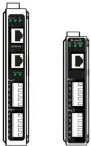
Part 1 A B C D E F G H I J K L M N O P Q R S T U V W X Y Z A B C D E F G H I J K L M N O P Q R S T U V W X Y ZFront View of the VESR922T and VESR902T Serial Server
LED INDICATORS(VESR90X)
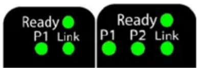
VESR9xx Serial Servers have three LED indicators: a Link LED, a Ready LED and two Serial Port LEDs.
text_image
Ready P1 Link Ready P1 P2 LinkLEDs on 1 and 2 Port Serial Servers
LINK LED
The Link LED illuminates (green) if the Ethernet connection is operating in 100BaseTX mode. The LED is off if the mode is 10BaseT. When the LED is blinking it indicates that there is data traffic on the Ethernet link.
READY LED
The Ready LED (green) blinks once per second if the system is operating correctly. If the LED is off, it indicates the system is not operating correctly.
SERIAL PORT LEDS
VESR901-x serial servers feature one serial port. VESR902D, and VESR902T-x serial servers feature two serial ports. Each serial port has an associated LED. Serial Port LEDs blink (green) when data is being transmitted or received on the serial port. When the LED is On it indicates the serial port is open.
LED INDICATORS (VESR92X)
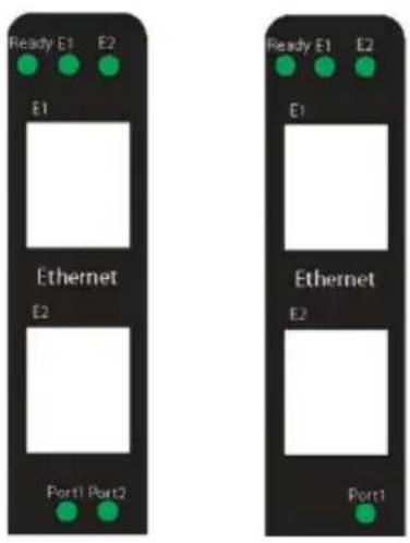
VESR92x Serial Servers have four LED indicators: E1 and E2 LEDs, a Ready LED and two Serial Port LEDs.
text_image
Ready E1 E2 E1 Ethernet E2 Port1 Port2 Ready E1 E2 E1 Ethernet E2 Port1 Port1LEDs on 1 and 2 Port Serial Servers
E1 and E2 LEDs
The E1 and E2 LEDs illuminate (green) if the Ethernet connection is operating in 100BaseTX mode. The LEDs are off if the mode is 10BaseT. When the LED is blinking it indicates that there is data traffic on the Ethernet link.
Ready LED
The Ready LED (green) blinks once per second if the system is operating correctly. If the LED is off, it indicates the system is not operating correctly.
Serial Port LEDs
VESR921-x serial servers feature one serial port. VESR922x, serial servers feature two serial ports. Each serial port has an associated LED. Serial Port LEDs blink (green) when data is being transmitted or received on the serial port. When the LED is On it indicates the serial port is open.
MODE SWITCH
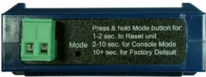
A recessed momentary reset switch is located on the top of the enclosure. To activate the switch, insert a small plastic tool through the hole in the enclosure and press lightly.
text_image
Press & hold Mode button for: 1-2 sec. to Reset unit Mode 2-10 sec. for Console Mode 10+ sec. for Factory DefaultTop View of the Serial Server
The Mode switch can be used to:
Initiate a Hardware Reset
Enter Console Mode
Reload factory defaults
Note: Refer to Section 3. Serial Server Setup and Connections for more information on using the Mode switch.
ETHERNET CONNECTOR
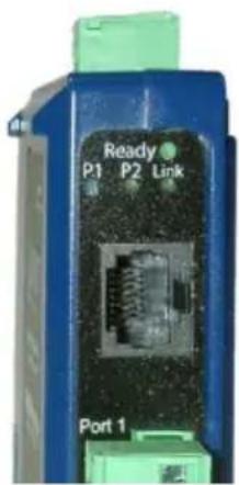
Serial server models using 10BaseT/100BaseTX network connections use an RJ45 receptacle. The serial server is connected to a standard Ethernet network drop using a straight-through RJ45 (male) Ethernet cable. VESR92x models feature a second RJ45 receptacle which acts an Ethernet pass-through connection. This connection functions similar to an Ethernet switch and allows the connection of other devices to the network.
text_image
Ready P1 P2 Link Port 1Ethernet Connector
Note: Refer to Appendix D for connection pin-outs.
FIBER OPTIC CONNECTORS
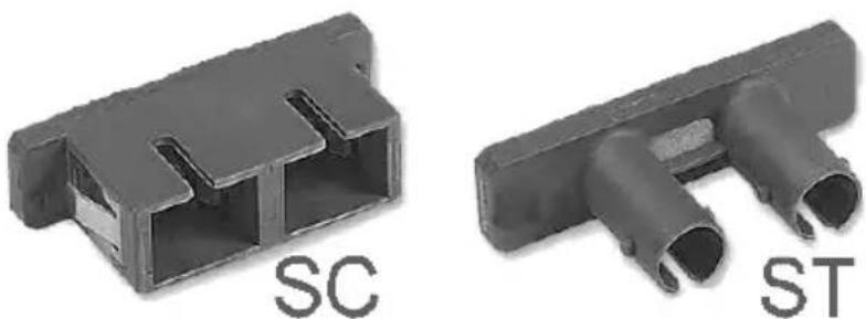
Serial server models using fiber Optic network connections use either SC or ST connectors, depending on the specific model.
natural_image
Two black plastic electronic component parts labeled SC and ST, showing internal structure and port (no text or symbols beyond labels)SC and ST Fiber Optic Cable Connectors
SERIAL PORT CONNECTORS
VESRxx Serial Servers use three serial port connector configurations, depending on the model:
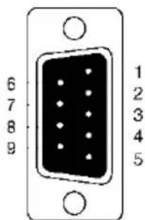
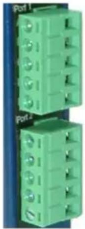
VESR901-x serial servers feature one serial port and use a DB-9M connector for RS-232 and a five-position removable terminal block for RS-422 and RS-485 connections.
VESR902D-x serial servers feature two serial ports, both using DB-9M connectors for RS-232, RS-422 and RS-485 connections.
VESR902T-x serial servers feature two serial ports, both using five-position removable terminal blocks for RS-232, RS-422 and RS-485 connections.
text_image
6 7 8 9 1 2 3 4 5DB-9 Female Serial Port Connector with Pinout
natural_image
Two green industrial electrical connector blocks with mounting holes, mounted on a blue surface (no text or symbols visible)Five-Position Pluggable Terminal Blocks
Note: Refer to Appendix D for connection pin-outs.
POWER CONNECTOR
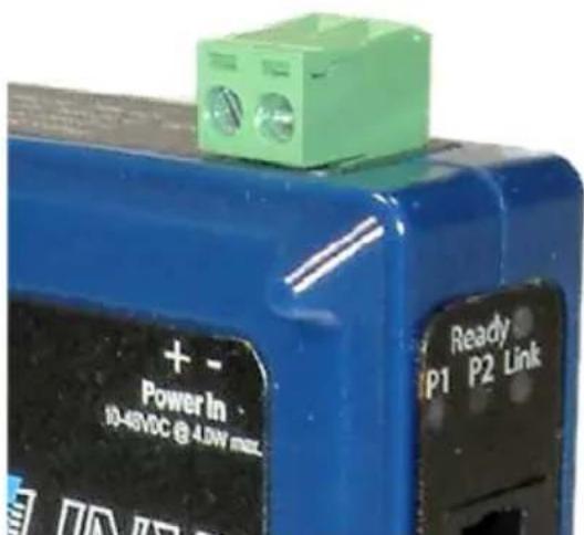
The power connector is a 5.08 mm 2-position pluggable terminal block.
text_image
+ - Power In 10-48VDC @ 4.0W mm Ready IP1 P2 LinkPower Connection
MOUNTING HARDWARE
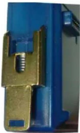
VESR9xx Serial Server modules can be DIN rail mounted. The DIN mounting clip and spring is included on each module.
natural_image
Close-up of a blue mechanical component with a metallic threaded part and a gold bracket (no visible text or symbols)DIN Clip on a Serial Server Module
SERIAL SERVER SETUP AND CONNECTIONS
This section describes how to setup and connect VESRxx Serial Servers.
Note: In this section devices to be connected to the serial server's serial connection are simply referred to as the "serial device".
CONNECTING THE POWER SUPPLY
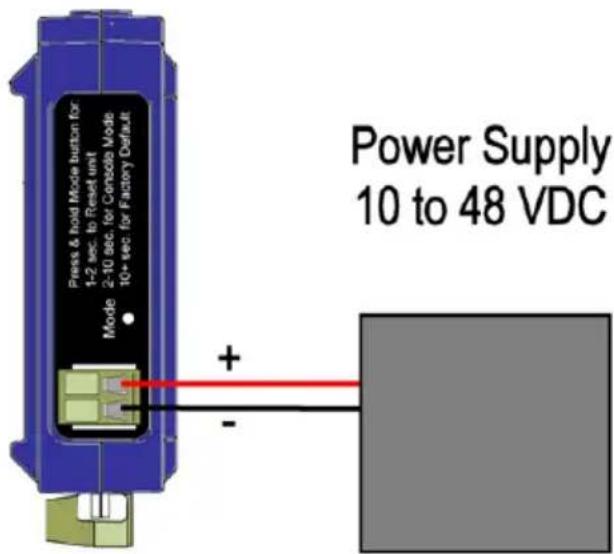
Connect a DC power supply to the power terminals on the top of the serial server. Polarity of the wires is indicated on the label on the side of the serial server. Acceptable voltages are between 10 VDC and 48 VDC. The power supply must be capable of supplying 4 Watts for VESR90x models and 6.0 Watts for VESR92x models.
text_image
Press & hold Mode button for 1-2 sec. to Reset unit Mode 2-10 sec. for Console Mode 10+ sec. for Factory Default Power Supply 10 to 48 VDCCONNECTING VESR9XX SERIAL SERVERS TO SERIAL DEVICES
VESR9xx Serial Servers can be configured to connect to serial devices using RS-232, RS-422, RS-485 2-wire and RS-485 4-wire.
RS-232 connections support eight signal lines plus Signal Ground. Signals are single ended and referenced to Ground. Default communications parameters are 9600, 8, N, 1 and no flow control implemented.
RS-422 connections support two signal pairs: TDA (-), TDB (+), RDA (-), RDB (+) and GND. The data lines are differential pairs (A & B) in which the B line is positive relative to the A line in the idle (mark) state. Ground provides a common mode reference.
RS-485 connections support 2-wire or 4-wire operation.
When configured for 4-wire operation the connection supports two signal pairs: TDA (-), TDB (+), RDA (-), RDB (+) and GND. This makes full-duplex operation possible. The data lines are differential pairs (A & B) in which the B line is positive relative to the A line in the idle (mark) state. Ground provides a common mode reference.
When configured for 2-wire operation the connection supports one signal pair: Data A (-) and Data B (+) signal channels using half-duplex operation. The data lines are differential with the Data B line positive relative to Data A in the idle (mark) state. Ground provides a common mode reference.
CONNECTING THE VESR901-X
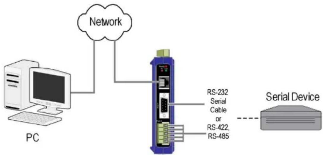
The VESR901-x has one serial connection that supports RS-232, RS-422 and RS-485 (2- and 4-wire). The unit has two connectors: a DB-9M connector and a 5-position terminal block.
If you select RS-232 mode when you configure the serial server, you must connect the serial device to the serial server via a serial cable. The VESR901 is a DTE. If the serial device is a DTE, use a null modem (cross-over) cable. If the serial device is a DCE, use a straight-through cable.
If you select RS-422 mode, RS-485 2-wire mode, or RS-485 4-wire mode when you configure the serial server, you must connect the serial device appropriately, via the 5-position terminal block.
Note: Refer to Appendix D for connector pinout information.
flowchart
graph TD
    A["PC"] --> B["Network"]
    B --> C["Serial Device"]
    C -.-> D["RS-232 Serial Cable or RS-422, RS-485"]
VESR901 Connections
CONNECTING THE VESR902T-X
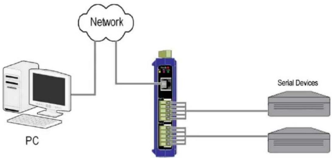
The VESR902T-x has two serial connections that support RS-232, RS-422 and RS-485 (2- and 4-wire). The unit has two connectors, both of which are 5-position terminal blocks. Make the appropriate connections to the terminal blocks to match the serial connection mode you select when configuring the serial server.
Note: Refer to Appendix D for connector pinout information.
flowchart
graph TD
    A["PC"] --> B["Network"]
    B --> C["Device 1"]
    B --> D["Device 2"]
    C --> E["Serial Devices"]
    D --> F["Serial Devices"]
VESR902T-x Connections
CONNECTING THE VESR902D-X
The VESR902D-x has two serial connections that support RS-232, RS-422 and RS-485 (2- and 4-wire). The unit has two connectors, both of which are DB-9M connectors. You must connect the serial device to the serial server via a serial cable. The VESR902D is a DTE. If the serial device is a DTE, use a null modem (cross-over) cable. If the serial device is a DCE, use a straight-through cable.
Note: Refer to Appendix D for connector pinout information.

flowchart
graph TD
    A["PC"] --> B["Network"]
    B --> C["Device 1"]
    B --> D["Device 2"]
    C --> E["Serial Devices"]
    D --> F["Serial Devices"]
VESR902D-x Connections
NETWORK CONNECTION (10BASET/100BASETX)
When connecting a serial server equipped with a 10BaseT/100BaseTX network connection (RJ45 connector) a standard network cable is connected from the serial server to a network drop. PCs configuring and/or communicating with the serial server are also connected to the network.
FIBER OPTIC CONNECTION
When connecting a serial server equipped with a fiber optic interface to a fiber optic link the appropriate fiber optic cable must be connected between the serial server and the network interface. Refer to the List of VESR9xx Serial Server Models at the beginning of this manual for a list of supported fiber types, distances and connectors.
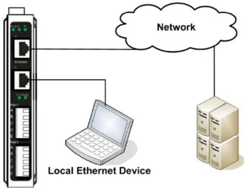
Ethernet Pass-through Port
VESR92x serial servers are configured with an additional RJ45 network port. This port can be used to connect additional Ethernet devices, such as a local workstation, to the network.
flowchart
graph TD
    A["Local Ethernet Device"] --> B["Client"]
    B --> C["Server"]
    C --> D["Network"]
    style A fill:#f9f,stroke:#333
    style D fill:#bbf,stroke:#333
Ethernet Pass-through Port
VESR9XX SERIAL SERVER CONFIGURATION CONNECTIONS
VESR9xx Serial Servers can be configured over the network or via a serial port.
CONFIGURING THE VESR9XX SERIAL SERVER VIA THE NETWORK CONNECTION
When configuring via the network, either Vlinx Manager software or the web interface can be used.
CONFIGURING WITH VLINX MANAGER
VESR9xx Serial Servers can be configured over the network Vlinx Manager software running on a PC.
To open Vlinx Manager:
From the Desktop, click Start→Programs→B+B SmartWorx→Vlinx→Vlinx Manager→VESR Serial Server
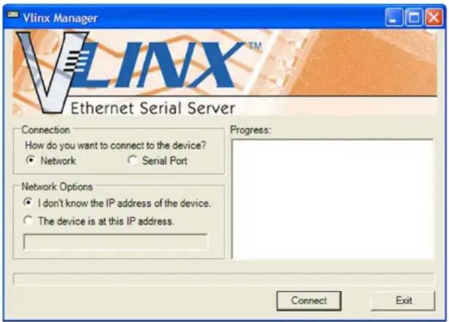
The Vlinx Manager Discovery window appears.
text_image
Vlinx Manager VLINX™ Ethernet Serial Server Connection How do you want to connect to the device? ● Network ○ Serial Port Network Options ● I don't know the IP address of the device. ○ The device is at this IP address. Progress: Connect ExitVlinx Manager Discovery Window
Configure your serial server as required.
Note: For more information on configuration options refer to Section 4: Description of Serial Server Properties.
CONFIGURING WITH THE WEB INTERFACE
VESR9xx Serial Servers can be configured over the network using a standard internet browser such as Internet Explorer or Firefox.
To open the web configuration interface:
- On a PC connected to the network, open a browser.
In the browser's address bar, type the IP address of the serial server.
Note: Your serial server comes from the factory pre-configured to receive an IP address from a DHCP Server. If DHCP assignment is not available it will default to 169.254.102.39
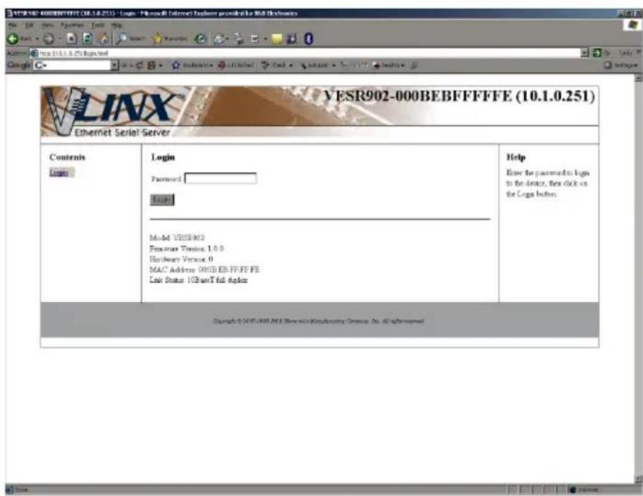
The web interface Login page appears.
text_image
VESR902-000BEBFFFFFE (10.1.0.251) Ethernet Serial Server Contents Login Login Password: Login Model VESR902 Password Version 1.0.0 Hardware Version 0 MAC Address 000B EB FF FF FE Late Status 10SmartT full adapter Help Enter the passwords to login to the device, then click on the Loga button. Copyright © 2007-2008-2009 Microsoft Publishing Group Inc. All rights reserved.Configure your serial server as required.
Note: For more information on configuration options refer to Section 4: Description of Serial Server Properties.
CONFIGURING THE VESR9XX SERIAL SERVER VIA THE SERIAL PORT (CONSOLE MODE)
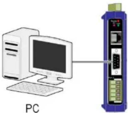
Your serial server can be configured via a serial port using Vlinx Manager. To use this feature the serial server's serial port must be connected to the serial port of a PC (using a null modem cable).
natural_image
Diagram showing a desktop computer connected to a server rack, labeled 'PC' (no text or symbols on the diagram itself)Console Mode Setup
To configure the serial server it must be put into Console Mode, using the Mode switch.
To enter Console Mode, press and hold the Mode switch for between two and ten seconds. The LED indicators respond as follows:
- The Ready LED blinks three times per second while the button is being pressed.
The serial server is in Console Mode when:
On the VESR901: Port 1 LED is On and the Ready LED is Off.
On VESR902x models: Port 1 LED is On and the Port 2 LED is Off.
To configure the serial server, open the Vlinx Manager software and set up the serial server's parameters as required.
Note: For more information on configuration options refer to Section 4: Description of Serial Server Properties.
To exit Console Mode, press and hold the Reset switch for two seconds, or turn off the power from the VESR9xx, wait a few seconds, and turn the power on again. The LEDs go back to their normal states when the device resumes normal operation.
VESR9XX SERIAL SERVER OPERATIONAL CONNECTIONS
VESR9xx Serial Servers can operate in Direct IP, Virtual COM Port and Paired Modes.
USING VESR9XX SERIAL SERVERS IN DIRECT IP MODE
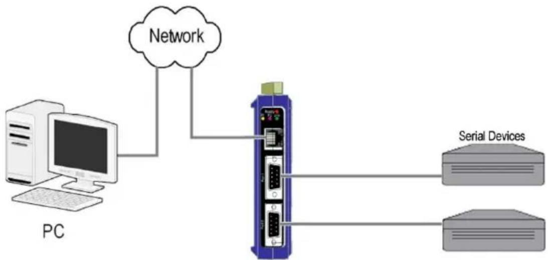
A Direct IP connection allows applications using TCP/IP or UDP/IP socket programs to communicate with the COM ports on the serial server. In this type of application the serial server is configured as a TCP or UDP server. The socket program running on the PC establishes a communication connection with the serial server. The data is sent directly to and from the serial port on the server.
To set up a Direct IP Mode connection:
- Connect the serial server to the network and a serial device as described in previous sections.
Configure the serial server with the appropriate network settings (using Vlinx Manager or the web interface).
Configure your software application with the appropriate IP address and port number to communicate with the serial device(s).
flowchart
graph TD
    A["PC"] --> B["Network"]
    B --> C["Serial Devices"]
    C --> D["Server"]
    style A fill:#f9f,stroke:#333
    style B fill:#ccf,stroke:#333
    style C fill:#cfc,stroke:#333
    style D fill:#fcc,stroke:#333
Direct IP and Virtual COM Port Connection
USING VESR9XX SERIAL SERVERS IN VIRTUAL COM PORT MODE
In Virtual COM Port Mode a PC can communicate across the network to the serial server as if the serial ports on the serial server are the PC's serial ports. When a virtual COM port is configured on the PC (using Vlinx Manager) a new COM port appears in the Device Manager. Windows programs using standard Windows API calls are able to interface to virtual COM ports. When a program on the PC opens the
new COM port, it communicates directly with the remote serial device connected to the serial server.
To set up a Virtual COM Port Mode connection:
- Connect the serial server to the network and a serial device as described in previous sections.
Configure the serial server for VCOM operation (using Vlinx Manager).
Configure your software application to communicate via the virtual COM port.
USING VESR9XX SERIAL SERVERS IN PAIRED MODE
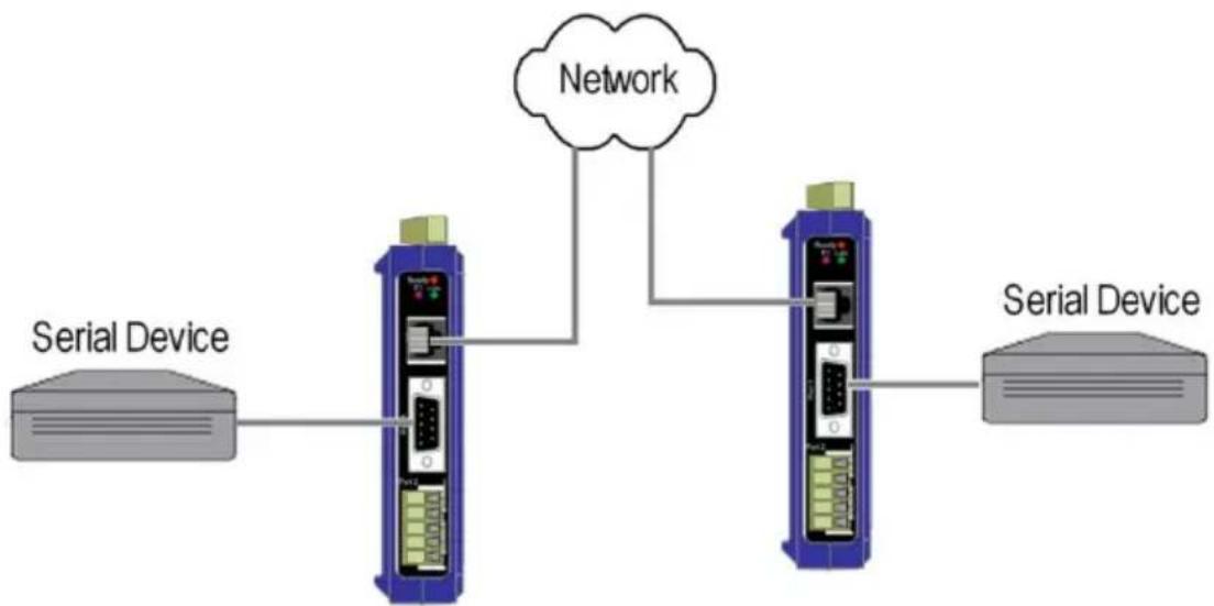
When using serial servers in Paired Mode, two serial servers (connected to serial devices via their serial ports) are connected to the network. The serial devices communicate directly, transferring data between devices as a point-to-point serial connection. Paired Mode set up as shown in the following diagram and configured using Vlinx Manager software or web interface.
flowchart
graph TD
    A["Serial Device"] --> B["Device 1"]
    B --> C["Network"]
    C --> D["Device 2"]
    D --> E["Serial Device"]
    style A fill:#f9f,stroke:#333
    style E fill:#bbf,stroke:#333
Paired Mode Setup
To set up a Paired Mode connection:
- Connect two serial servers to serial devices and to the network.
Configure the serial server for Paired Mode operation (using Vlinx Manager or the web interface).
INITIATING A HARDWARE RESET ON THE SERIAL SERVER
To initiate a Hardware Reset on the serial server, press and hold the Mode switch for 0 to 2 seconds, and then release it. The LED indicators respond as follows:
- The Ready LED blinks three times per second while the button is being pressed.
The serial server is in Reset Mode when:
On the VESR901: Port 1 LED is On and the Ready LED is Off.
On VESR902x models: Port 1 LED is On and the Port 2 LED is Off.
The LEDs go back to their normal states when the device resumes normal operation.
RELOADING FACTORY DEFAULTS
To reload Factory Defaults, press and hold the Mode switch for more than 10 seconds. The LED indicators respond as follows:
- The Ready LED blinks three times per second while the button is being pressed.
The serial server is in Factory Default Mode when:
On the VESR901: Port 1 LED and the Ready LED are both On.
On VESR902x models: Port 1 LED and the Port 2 LED are both On.
The serial server reloads all factory default configuration parameters.
The LEDs go back to their normal states when the device resumes normal operation.
Note: Factor default parameters are listed in Appendix A
DESCRIPTION OF SERIAL SERVER PROPERTIES
The following serial server properties are ordered alphabetically to assist you in finding the information you need.
BAUD RATE
Baud Rate is the communication speed of the link between the serial server and the device attached to its serial port. Both these devices must be configured to operate at the same baud rate. Baud rate values range from 75 to 230,400 Baud. (Refer to Appendix B for specific baud rates that are supported.)
CHARACTER COUNT
Character Count controls the maximum number of characters to buffer before sending the characters to the network. Larger values decrease the number of network packets, but increase the amount of time to receive characters. Smaller values increase the number of network packets, but decrease the amount of time to receive characters. The range is 1 through 65535.
CONFIGURATION FILES
Configuration files contain all configuration settings for the serial server. When the serial server settings have been configured you can save the settings using Vlinx Manager. Existing configuration files can be Opened (from Vlinx Manager), which loads them into the serial server. This allows the same configuration to be applied to multiple serial servers, or to reload a previously used configuration.
DATA/PARITY/STOP
The number of Data bits, type of Parity and number of Stop bits selected define the serial port parameters at which the serial server will operate. These parameters must be configured to match the parameters set on the serial device connected to the serial server's serial port.
Data Bits controls the number of bits of data in each character. Options include 5, 6, 7 or 8 data bits.
Parity controls the error checking mode. Options are No Parity, Odd, Even, Mark or Space.
Stop Bits controls the number of bits to indicate the end of a character. Options include 1, 1.5 and 2. (1.5 bits is only valid when 5 data bits is selected, which is rare. The 2 stop bits setting is only valid when 6, 7 or 8 data bits is selected.)
DEFAULT GATEWAY
The Default Gateway address sets the default route to remote networks, enabling users to access the serial server from outside the local network.
DELIMITER 1, DELIMITER 2 AND DELIMITER REMOVAL
Delimiters and Delimiter Removal enable you to control how characters received on a serial port are sent across the network. Delimiters are ASCII characters specified by the user when configuring the serial server. The serial server takes action when it recognizes the specified character(s) on its serial port.
DELIMITER 1
Delimiter 1 is a start delimiter. The range of ASCII values is 0 through 255.
DELIMITER 2
Delimiter 2 is an end delimiter. The range of ASCII values is 0 through 255.
DELIMITER REMOVAL
Delimiter Removal controls removing of Delimiter 1 and Delimiter 2 from the received characters before the received characters are sent to the network.
HOW DELIMITERS WORK
When only Delimiter 2 (the end delimiter) is enabled, characters received by the serial port are accumulated in a buffer. When the end delimiter is received on the serial port, the buffered characters, including the end delimiter, are sent to the network. All characters received after the end delimiter are again buffered until another end delimiter is received.
When both Delimiter 1 (start delimiter) and Delimiter 2 (end delimiter) are enabled, characters received by the serial port will be discarded until the start delimiter character is detected on the serial port. The serial server then buffers the start delimiter character and all subsequent characters received after it until the end delimiter is detected. When the end delimiter is received, the buffered characters, including the start and end delimiters, are sent to the network.
When Delimiter Removal is enabled it removes the delimiter character(s) before sending the other characters across the network.
DHCP
DHCP (Dynamic Host Configuration Protocol) is a protocol used on special servers that supply IP addresses to network nodes on request.
When DHCP is enabled on the serial server, on power up it sends a DHCP request to the DHCP server, which assigns a dynamic IP address, subnet mask, and default gateway to the serial server.
When DHCP is disabled (static IP addressing), the IP Address, Subnet Mask and Default Gateway fields must be set manually by entering the appropriate addresses in these fields. If you do not know what addresses to use in these fields, ask your network administrator.
Notes: This product is factory defaulted to the DHCP mode. It is intended that your network's DHCP Server provide the IP address assignment. If there is not a DHCP server on your network, the device will default to IP address 169.254.102.39.
A dynamic address assigned by the DHCP server may change if the server loses the Ethernet connection or power is removed. If a device on the network that normally communicates with the serial server is configured to communicate with a specific IP address of the serial server, and the IP address has been changed, the device will not be able to communicate with the serial server.
FIRMWARE VERSION
The Firmware Version number (Vx.x.x) indicates the serial server's currently loaded firmware release. From time to time new firmware is made available and can be uploaded into the serial server using Vlinx Manager.
FLOW CONTROL
Flow Control determines the type of handshaking that is used to control sending and receiving of messages. Options include No Flow Control, Hardware Flow Control (RTS/CTS) and Software Flow Control (XON/XOFF). The Flow Control setting must match the requirements of the serial device connected.
Note: Select No Flow Control when setting the port as RS-422 or RS-485 4-wire.
FORCED TRANSMIT
Forced Transmit controls the maximum amount of time that characters can be buffered before sending the characters to the network. Larger values decrease the number of network packets, but increase the amount of time to receive characters. Smaller values increase the number of network packets, but decrease the amount of time to receive characters. The range is 1 through 65535.
HARDWARE VERSION
The Hardware Version number of the serial server hardware is displayed on the Login page of Vlinx Manager.
INTER-CHARACTER TIMEOUT
Inter-character Timeout controls the maximum duration between received characters before sending the characters to the network. Larger values may decrease
the number of network packets, but increase the amount of time to receive characters. Smaller values may increase the number of network packets, but decrease the amount of time to receive characters. The range is 1 through 65535.
IP ADDRESS
Software or hardware attempting to access the serial server via the network must know the IP Address of the server. In DHCP mode (factory default), the serial server requests and receives a dynamic IP address from a DHCP server when it first connects to the network. If there is not a DHCP Server on your network, this device will automatically default to IP Address 169.254.102.39. If the serial server is unable to connect to your network using this address, there are two methods to manually configure the IP Address.
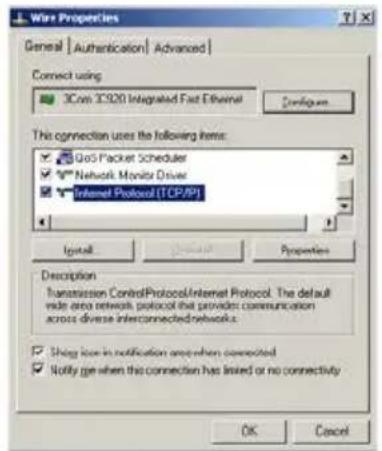
- Method One: Change your PC Network to Match the Serial Server a. Open the network connection on your PC
text_image
Wire Properties General | Authentication | Advanced | Connect using 3Com 3C920 Integrated Fast Ethernet Configure... This connection uses the following items: QoS Packet Scheduler Network Monitor Driver Internet Protocol (TCP/IP) Install Properties Description Transmission ControlProtocol/Internet Protocol. The default wide area network protocol that provides communication across diverse interconnected networks. Thing like to notification areas when connected Notify go when this connection has linked or no connectivity OK Cancelb. Click on Internet Protocol (TCP/IP) and click
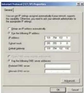
IP Address = 169.254.102.1
Subnet Mask = 255.255.255.0
Default Gateway = 169.254.102.100
text_image
Internet Protocol (TCP/IP) Properties General You can get IP settings assigned automatically if you network supports this capability. Otherwise, you need to ask our network administrator to the appropriate IP settings. □ Listen an IP address automatically □ Use the following IP address: IP address: 103 254 102 1 Cybernet mask: 265 295 0 0 Default gateway: 103 254 102 10C □ Logitting DNS server addresses □ Log the following DNS server addresses: Enlarged DNS server: Enlarged DNS server: Advanced... OK Cancelc. Use the Vlinx™ Manager Software to search for, discover, and configure the unit.
- Method Two: Change the serial server's network setting to match your PC using Console Mode
a. Connect a null modem serial cable (crossover cable) from Port 1 on the serial server to an available COM port on your PC.
b. Open Hyper Terminal or similar serial emulation software and connect to the COM port used in the step above. Ensure the port is configured to 115,200 baud, 8 data bits, and 1 stop bit.
c. Enter Console Mode. Press and hold the serial server's RESET SWITCH for 2 to 10 seconds. The LED indicators will respond as follows:
| MODEL | PORT 1 LED | PORT 2 LED | READY LED |
| 1 Port | OFF | N/A | ON |
| 2 Port | OFF | ON | OFF |
d. Release the RESET button. The READY LED will blink once per second for 5 seconds. This indicates that the serial server is re-booting in Console Mode.
e. When the serial server has successfully restarted in Console Mode, the READY LED will be OFF and the PORT 1 LED will be on.
f. Open the Vlinx™ Manager Software and select "Serial Port" as the method to connect to the device.
g. After logging in, click on
h. Un-check the box next to "I want DHCP to setup the Network."
i. Re-configure the serial server's Network Settings to something within the range of your PC's Network Setting. For example
If your PC is configured to:
IP Address = 192.168.0.1
Network Mask = 255.255.255.0
Default Gateway = 192.168.0.100
Configure the serial server to:
IP Address = 192.168.0.50
Network Mask = 255.255.255.0
Default Gateway = 192.168.0.100
j. Save the settings and remove power from the serial server.
k. Apply power to the serial server. Open the Vlinx™ Manager Software and select “Network” as the method to connect to the serial server
1.
LINK STATUS
Link Status of the currently selected serial server is shown on the Login page of Vlinx Manager. Link status indicates the type of Ethernet connection between the computer and serial server. It will either display 10BaseT or 100BaseTX in full duplex or half duplex. Link status is dependent on the LAN, switches, hubs used in the LAN topology.
MAC ADDRESS
The MAC Address is a hardware level address of the serial server that cannot be changed. It is assigned in the factory. Every Ethernet device manufactured has its own unique MAC address. The MAC address of each serial server is printed on the device's label. The MAC address of the currently selected serial server is also displayed on the Login page of Vlinx Manager.
MODEL
The Model number of the currently selected serial server is displayed on the Login page of Vlinx Manager.
NETWORK PROTOCOLS
Network Protocols available for use on VESR9xx serial servers include TCP, UDP, VCOM and Paired Mode.
NETWORK WATCHDOG
Network Watchdog controls the duration of network inactivity when a network connection is determined idle and causes the connection to be forced closed. The range is 1 through 65535 milliseconds.
PAIRED MODE
Paired Mode enables two serial servers to operate across the network like a "wire replacement" between two serial devices. (Paired Mode is also called SERIAL TUNNELING.) Serial devices connected to serial servers on each end of the link can communicate as it they were connected by a serial cable.
For Paired Mode to work one serial server must be configured as a TCP server and the other as a TCP client.
The serial server configured as the TCP client initiates connections. You must set up the IP address and port number of the server that you want the client (serial server) to communicate with. You also select whether you want the serial server to connect at power up or only when it receives data from the device connected to its serial port.
The serial server configured as a TCP server waits for connections to be initiated by another network device. You must set up the TCP port number on which it will listen
for connections and set the maximum (up to four) number of simultaneous connections it will accept. You can filter the connections it will accept based on specific IP addresses or ranges of IP addresses that you specify.
PASSWORD
When you first receive the VESR9xx serial server from the factory the Password is blank so that you can initially access the serial server without entering a value into this field. To ensure security you should create and save a password the first time you configure the serial server. After a password has been set up it must be entered each time you login to Vlinx Manager. The password is used to access the configuration pages from the Vlinx Manager Login page and can be changed from the General page.
SERIAL INTERFACE MODES
Four serial interface modes of operation are:
RS-232 - Point-to-point serial communications connection used by PC COM ports and many other systems. Capable of baud rates up to 115.2 kbaud over short distances (typically 50 feet). Typically uses DB-9 connectors but terminals are also used on VESR9xx serial servers.
RS-422 - Point-to-point communications using a transmit pair and a receive pair. RS-422 can operate at higher speeds and longer distances than RS-232. Typically uses two shielded twisted pairs and screw terminals but DB-9 connectors are also used on VESR9xx serial servers.
RS-485 2-wire - Similar speed and distance specifications as RS-422 but allows multidrop connections. Typically uses one shielded twisted pair and screw terminals but DB-9 connectors are also used on VESR9xx serial servers.
RS-485 4-wire - Similar speed and distance specifications as RS-422 but allows full-duplex connections. Typically uses two shielded twisted pairs and screw terminals but DB-9 connectors are also used on VESR9xx serial servers..
Select the appropriate serial interface mode for the type of connection between the serial server's serial port and the device connected to it.
Note: Refer to the Appendix D for connector and pin-out details.
SERIAL SERVER NAME
Serial Server Name is a unique name assigned to the serial server. It must be a valid hostname as defined by RFC-952 and RFC-1123. The rules are:
It must consist only of the characters "A" to "Z", "a" to "z", "0" to "9" or "-"
It can start or end with a letter or a number, but it must not start or end with a "-". It must not consist of all numeric values.
SERVER SERIAL PORT NUMBER
The Server Serial Port Number of the currently selected port is shown in this field. VESR901-x serial servers feature one serial port.
VESR902D-x and VESR902T-x serial servers feature two serial ports.
SERIAL WATCHDOG
Serial Watchdog controls the duration of serial inactivity when the serial port is determined idle and causes all connections for that serial port to be forced closed. The range is 1 through 65535 milliseconds.
SUBNET MASK
The Subnet Mask specifies the network mask the serial server uses when on a subnetted network.
For a Class A network (IP addresses 0.0.0.0 through 127.255.255.255) the default subnet mask is 255.0.0.0.
For a Class B network (IP addresses 128.0.0.0 through 191.255.255.255) the default subnet mask is 255.255.0.0
For a Class C network (IP addresses 192.0.0.0 through 233.255.255.255) the default subnet mask is 255.255.255.0
For a Class D network (IP addresses 224.0.0.0 through 239.255.255.255) and Class E Networks (IP addresses 240.0.0.0 through 255.255.255.255) the subnet mask is ignored.
VESR9xxserial servers come from the factory with a default subnet mask value of: 255.255.255.0
TCP (TRANSMISSION CONTROL PROTOCOL)
TCP (Transmission Control Protocol) provides reliable connection-oriented network communication with error checking. In TCP mode the serial server can be configured as a client or a server.
When the serial server is configured as a TCP client it initiates connections with a server on the network. You must set up the IP address and port number of the server that you want the client (serial server) to communicate with. You also select whether the serial server is to connect at power up or only when it receives data from the device connected to its serial port.
When the serial server is configured as a TCP server it waits for connections to be initiated by another network device. You must set up the TCP port number that it will listen to for connections and set the maximum (up to four) number of simultaneous connections it will accept. You can filter the connections it will accept based on specific IP addresses or ranges of IP addresses that you specify.
UDP (USER DATAGRAM PROTOCOL)
UDP (User Datagram Protocol) enables applications using UDP socket programs to communicate with the serial ports on the serial server. UDP protocol provides connectionless communications, which allows data to be broadcast to and received from multiple nodes on a network. (Because it is a connectionless protocol UDP does not guarantee the delivery of a datagram and the datagram is only be sent once.)
In UDP mode, if you want to control what network node receives data, you must specify the IP address and UDP port the data will be sent to. You can choose to send to:
Nobody
All nodes at a specific UDP port number. (This is called broadcast.)
Specific IP addresses and UDP port numbers. (This is called unicast.)
A range of IP addresses and UDP port numbers. (This is called unicast range.)
You can also configure the serial server to receive from nodes on the network using the same list of configuration options.
VCOM (VIRTUAL COM PORT)
When the Network Protocol is set to VCOM (Virtual COM Port) the serial server communicates over the network with a PC, acting as a remote COM port for the computer.
Both the serial server and the computer must be configured for VCOM operation. Virtual COM ports can be set up on the PC using the Vlinx Manager software.
UPGRADING THE SERIAL SERVER FIRMWARE
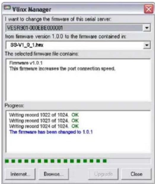
Occasionally, updated firmware may become available for your serial server. The firmware can be upgraded using the Zlinx Manager software. The following procedure describes the firmware updating process:
- Click the Upgrade button to open the Firmware Upgrade dialog box.
text_image
Vlinx Manager I want to change the firmware of this serial server: VESR901-000EBE000001 from firmware version 1.0.0 to the firmware contained in: SS-V1_0_1.hex The selected firmware file contains: Firmware v1.0.1 This firmware increases the port connection speed. Progress: Writing record 1022 of 1024. OK Writing record 1023 of 1024. OK Writing record 1024 of 1024. OK The firmware has been changed to 1.0.1 Internet... Browse... Upgrade CloseFirmware Upgrade Dialog Box
The name of the currently selected serial server appears in the top drop down list. Other serial servers (that have already been discovered) can be selected from the drop down list, if desired.
The current firmware version of the selected serial server is shown in the text below the serial server name.
Information about the selected firmware file is shown in the third text box.
DOWNLOADING FIRMWARE FILES
The Firmware File list (second box) displays all firmware files in the firmware installation folder. Only firmware that is compatible with the selected serial server is available in this list.
To download the latest firmware files from the Internet:
- Go to the "Tech Support" tab on the B+B SmartWorx web site.
http://www.bb-elec.com/Tech-Support/Search-for-Documents-and-Software.aspx - Choose "Search for Documents and Software".
- Enter your product model number in the "Enter Keyword/Model Number" box.
- Click "Find".
- Select and download your file to your local firmware folder.
UPLOADING THE FIRMWARE TO THE SERIAL SERVER
To upgrade the firmware:
- In the Serial Server Selection drop down list, select the serial server to be upgraded.
In the Firmware Description drop down list, select the firmware to upload to the serial server.
Click the Upgrade button.
Progress Bar and Progress Box provides information on the progress of the transfer.
In the Firmware File drop down list, select the firmware file to upload to the serial server.
Click Upgrade.
The Progress box and Progress bar display information on the upgrading process.
When the upgrade process is complete, click Close.
DIAGNOSTICS
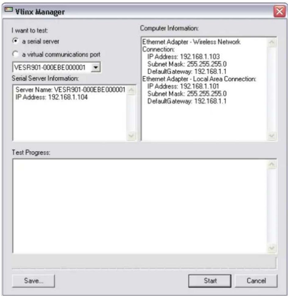
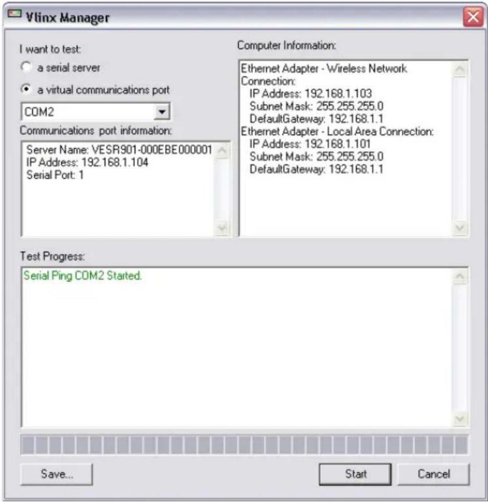
Clicking the Diagnostics icon opens the Diagnostics dialog box and enables you to check the operation of connected serial servers and VCOM ports on the local computer.
The Computer Information box displays information about the type of network connections, the IP addresses, Subnet Masks and Default Gateways in use.
text_image
Vlinx Manager I want to test: ● a serial server ○ a virtual communications port VESR901-000EBE000001 Serial Server Information: Server Name: VESR901-000EBE000001 IP Address: 192.168.1.104 Computer Information: Ethernet Adapter - Wireless Network Connection: IP Address: 192.168.1.103 Subnet Mask: 255.255.255.0 DefaultGateway: 192.168.1.1 Ethernet Adapter - Local Area Connection: IP Address: 192.168.1.101 Subnet Mask: 255.255.255.0 DefaultGateway: 192.168.1.1 Test Progress: Save... Start CancelDiagnostics Dialog Box
TESTING A SERIAL SERVER CONNECTION
To run diagnostics on a serial server:
- Click the Diagnostics icon.
The Diagnostics dialog box appears.
Select the option: a serial server
In the drop down box select the specific serial server you want to check.
Click the Start button
Information about the progress of the pinging process is displayed in the Test Progress box.
Testing a Serial Server Connection
TESTING A VIRTUAL COM PORT
To run diagnostics on a virtual COM port:
1. Click the Diagnostics icon.
The Diagnostics dialog box appears.
Select the option: a virtual communications port
In the drop down box select the specific COM port you want to check.
Click the Start button. Information about the progress of the pinging process is displayed in the Test Progress box.
text_image
Vlinx Manager I want to test: a serial server a virtual communications port COM2 Communications port information: Server Name: VESR901-000EBE000001 IP Address: 192.168.1.104 Serial Port: 1 Computer Information: Ethernet Adapter - Wireless Network Connection: IP Address: 192.168.1.103 Subnet Mask: 255.255.255.0 DefaultGateway: 192.168.1.1 Ethernet Adapter - Local Area Connection: IP Address: 192.168.1.101 Subnet Mask: 255.255.255.0 DefaultGateway: 192.168.1.1 Test Progress: Serial Ping COM2 Started. Save... Start CancelTesting a VCOM Port
APPENDIX A: DEFAULT SERVER SETTINGS
| Setting | Default Value |
| Server Name | MODEL NUMBER |
| Serial Number | printed on side of unit |
| Password | password field is blank from factory |
| DHCP | Enable |
| IP Address | BASED ON DHCP SERVERIf a DHCP assignment is not available, the device will default to 169.254.102.39 |
| Net Mask | 255.255.255.0 |
| Gateway | 169.254.102.100 |
| MAC Address | Fixed - see bottom label |
| Firmware Version | X.X.X (Current Version) |
| Hardware Version | X.X (Current Version) |
| Port | 1, 2 |
| Serial port mode | RS-232 |
| Baud Rate | 9600 |
| Data bits | 8 |
| Parity | None |
| Stop bits | 1 |
| Flow Control | None |
| Protocol | TCP |
| Serial timeout | 0 seconds |
| TCP alive timeout | 0 minutes |
| Connection Mode | Server |
| Delimiter HEX 1 | 00 |
| Delimiter HEX 2 | 00 |
| Remove delimiters | Disable |
| Force transmit | 0 ms |
| Inter-character timer | 0 ms |
| Character count | 0 |
| TCP/UDP port | Port 1 = 4000, Port 2 = 4001 |
| Max connection | 1 |
GENERAL SPECIFICATIONS
| Hardware and included accessories | Device | Serial Server |
| CD | CD with Vlinx Manager software for Windows 2000, XP (32/64 bit), 2003 Server (32/64 bit), Vista (32/64 bit), 2008 Server (32/64 bit), Windows 7 (32/64 bit) | |
| Optional Accessories | Cable | 232NM9 Null Modem Crossover Cable for DTE to DTE connection |
| Rail | ERS35 one-meter length of steel 35mm DIN Rail | |
| Configuration Options | Via serial port | Using Vlinx Manager via a serial connection, (press Reset button to enter Console Mode) |
| Via network | Using Vlinx Manager via a Ethernet connection | |
| Using a standard web browser such as Internet Explorer 6.0/7.0 or Firefox 1.5/2.0 | ||
| Software | Vlinx Manager for serial server configuration | Windows 2000, XP (32/64 bit), 2003 Server (32/64 bit), Vista (32/64 bit), 2008 Server (32/64 bit), Windows 7 (32/64 bit) |
| Environment | Operating Temperature | -40 to 80 °C (-40 to 176 °F) |
| Storage Temperature | -40 to 85 °C (-40 to 185 °F) | |
| Operating Humidity | 10 to 95% non-condensing | |
| Maximum Ambient Surrounding Air Temp | 80 °C | |
| Certifications | FCC | Part 15 Class A |
| CE | ||
| UL | File E222870 | |
| UL Class1 Div2 | Groups A, B, C, D (HAZLOC) File E245458 | |
| TS2 | ||
| Enclosure | Rating | IP30 |
| Mounting | DIN rail mount (35 mm) | |
| Dimensions (VESR90x) | 1.2 x 3.3 x 4.7 in (3.1 x 8.4 x 11.9 cm) | |
| Dimensions (VESR92x) | 1.2 x 4.3 x 6.2 in (3.1 x 10.9 x 15.7 cm) | |
| Power Supply | Voltage Requirements | 10 to 48 VDC (58 VDC Maximum) |
| Power Consumption | VESR90x – 4.0W (max)VESR92x – 6.0W (max) | |
| Terminal Blocks | Wire Size 28 to 16 AWG | |
| Wire Type Copper Wire | Only | |
| Tightening Torque | 5 KG-CM | |
| Wire Temp Rating 105 °C Minimum | ||
| Sized for 60 °C Ampacity | ||
| Note: | One Conductor Per Terminal | |
| Switches | Reset button | Hold in for 0 to 2 seconds for hardware resetHold in for 2 to 10 seconds for Console Mode (Do a hardware reset or recycle power to exit Console Mode)Hold in for more than 10 seconds to reset to factory defaults |
| Indicators | Serial LED(one per port) | Color = GreenOn = Port openBlink = Data traffic |
| Link LED (VESR 90x)E1 / E2 LED(VER92x) | Color = GreenOn = 100BaseTXOff = 10BaseTBlink = Data traffic | |
| Ready LED | Color = GreenBlink (once per second) = System OKOff = System NOT OK | |
| Connectors | 10BaseT/100BaseTXEthernet | Single RJ-45F (8 pin) |
| SC fiber | SC connector | |
| ST fiber | ST connector | |
| Serial | ESR901-x: one DB-9M connector | |
| ESR902D-x: Two DB-9M connectors | ||
| ESR902T-x: Two pluggable lockable 5.08 mm terminal blocks | ||
| DC Power | 5.08mm 2-position pluggable, lockable terminal block | |
| Serial Interfaces | Mode Selection | RS-232/422/485 software selectable |
| RS-232 lines | TXD, RXD, RTS, CTS, DTR, DSR, DCD, GND | |
| RS-422 lines | TXDA(-), TXDB(+), RXDA(-), RXDB(+), GND | |
| RS-485 lines (2 wire) | Data(-), Data(+), GND | |
| RS-485 lines (4 wire) | TXDA(-), TXDB(+), RXDA(-), RXDB(+), GND | |
| Baud Rates | 75, 150, 300, 600, 1200, 2400, 4800, 7200, 9600, 14400, 19200, 28800, 38400, 57600, 115200, 230400 | |
| Data Bits | 5, 6, 7, 8 | |
| Parity | None, even, odd, mark, space | |
| Stop bits | 1, 1.5, 2 | |
| Flow control | None, RTS/CTS, XON/XOFF | |
| RS-422/485 biasing | Auto 4.7K ohm pullups and pulldowns | |
| RS-422/485 termination | Auto termination with thru hole resistor (user supplied) | |
| RS-485 data control | Auto control via MCU | |
| Memory | Serial Memory | 8 KB per port |
| Network Memory | 4 KB | |
| I/P Port Addresses | 5300 | Heartbeat & Configuration setting in TCP Mode (i.e. Pair Mode) |
| 8888 | VESR9xx update | |
| Network Communications | LAN | 10/100 Mbps Auto-detecting 10BaseT or 100BaseTX |
| Network Physical Layer Standards | Ethernet | IEEE 802.3 autodetecting & auto MDI/MDX 10BaseT and 100BaseTX |
| Protocols Supported | TCP, IPv4, UDP, ARP, HTTP 1.0, ICMP/PING, DHCP/BOOTP | |
| IP Mode | Static, DHCP | |
| TCP/UDP | User definable | |
| UDP | Unicast or Multicast | |
| Connection Modes | Server, Client, VCOM, Paired | |
| Client Connection | At power up or upon data arrival | |
| Search | Serial direct COM and Ethernet autosearch or specific IP | |
| Diagnostics | Display PC IP, ping, test VCOM, save test config (text readable) | |
| Firmware Upgrade | Via serial, Ethernet or auto web search | |
| Character count | 0 to 65535 | |
| Delimiters | Hex 1 | 00 to FF (send serial data if delimiter hex 1 only is set and received) |
| Hex 2 | 00 to FF (send serial data if delimiter hex 1 and 2 are set and received) | |
| Timeouts | Inter-character | 0 to 65535 ms |
| Serial | 0 to 65535 sec | |
| TCP alive | 0 to 255 min | |
| Force transmit | 0 to 65535 ms | |
| Max character count | 0 to 8192 bytes | |
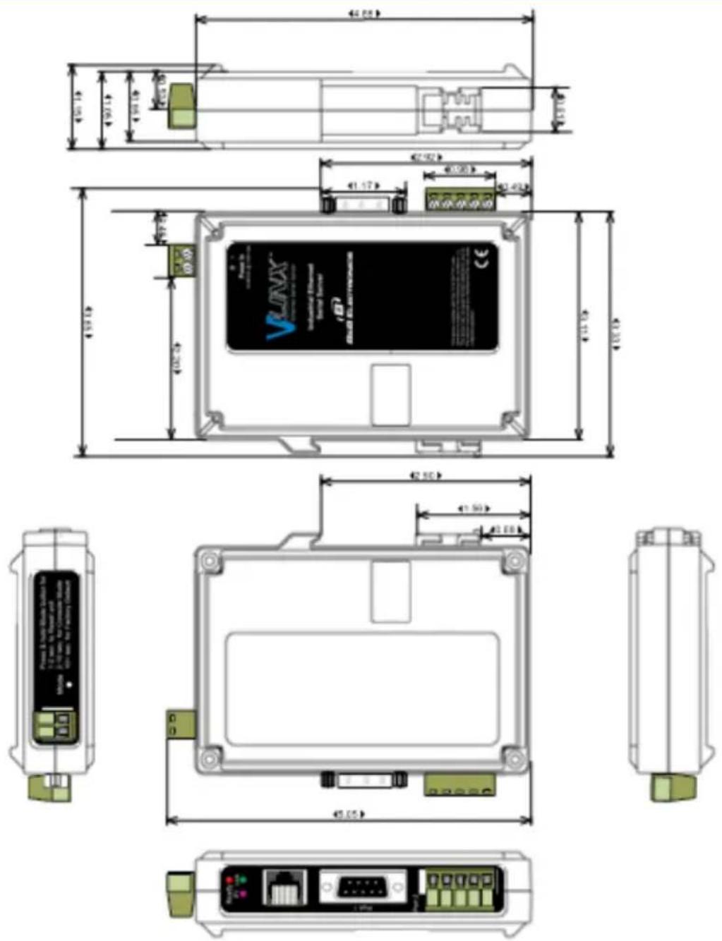
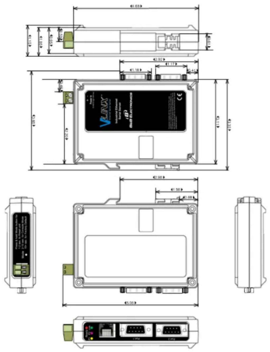
APPENDIX C: DIMENSIONAL DIAGRAMS
text_image
Technical schematic diagram of an electronic device with labeled components and dimensional annotations in millimeters.Dimensional Diagram of a VESR901 Serial Server
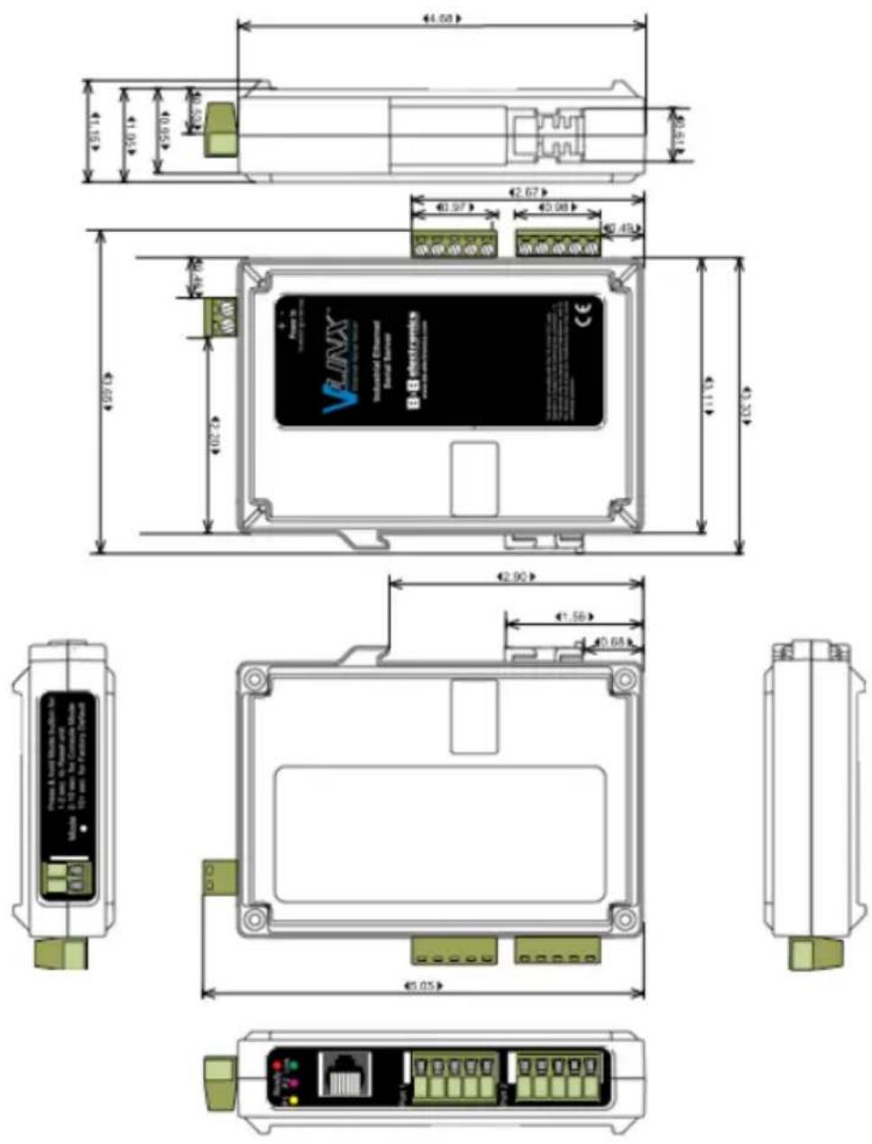
Dimensional Diagram of a VESR902D Serial Server
Dimensional Diagram of a VESR902T Serial Server
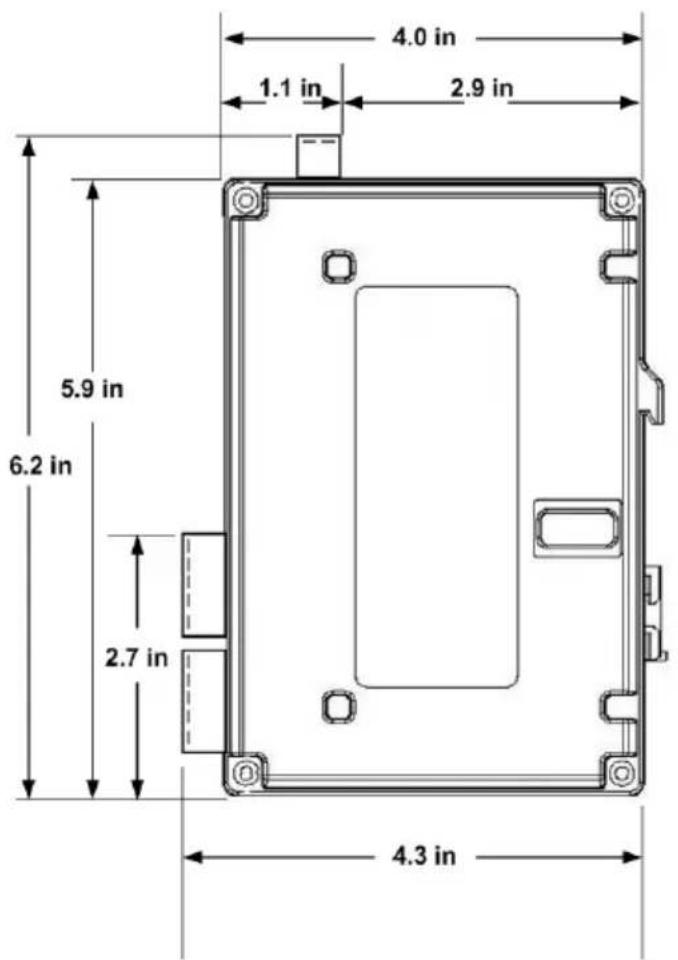
text_image
4.0 in 1.1 in 2.9 in 5.9 in 6.2 in 2.7 in 4.3 in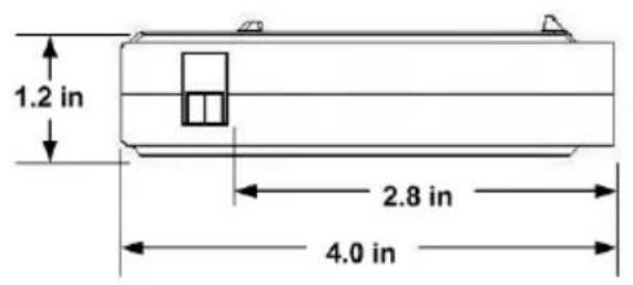
text_image
1.2 in 2.8 in 4.0 inVESR901 & VESR921 SERIES
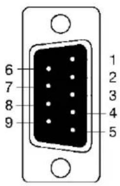
text_image
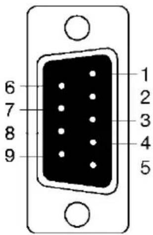
6 7 8 9 1 2 3 4 5| DB9 M Pin | Direction | RS-232 |
| 1 Input DCD | ||
| 2 Input RXD | ||
| 3 Output TXD | ||
| 4 Output DTR | ||
| 5 --- GND | ||
| 6 Input DSR | ||
| 7 Output RTS | ||
| 8 Input CTS | ||
| 9 Input RI |
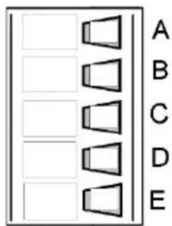
text_image
A B C D E| Terminal | RS-422/485 4-Wire | RS-485 2-Wire |
| A | TDA (-) | Data A (-) |
| B | TDB (+) | Data B (+) |
| C | RDA (-) | --- |
| D | RDB (+) | --- |
| E | GND | GND |
text_image
6 7 8 9 1 2 3 4 5| DB-9M Pin | RS-232 | Direction (RS-232) | RS-422/485 4-Wire | RS-485 2-Wire |
| 1 | DCD | Input | RDA (-) | --- |
| 2 | RD | Input | RDB (+) | --- |
| 3 | TD | Output | TDB (+) | Data A (-) |
| 4 | DTR | Output | TDA (-) | Data B (+) |
| 5 | GND | --- | GND | GND |
| 6 | DSR | Input | --- | --- |
| 7 | RTS | Output | --- | --- |
| 8 | CTS | Input | --- | --- |
| 9 | RI | Input | --- | --- |
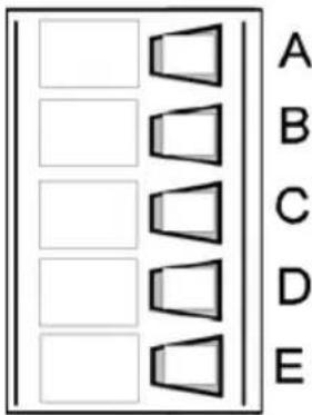
text_image
A B C D E| Terminal | RS-232 | Direction (RS-232) | RS-422 | RS-485 |
| A | RTS | Output | TDA (-) | Data A (-) |
| B | TD | Output | TDB (+) | Data B (+) |
| C | CTS | Input | RDA (-) | --- |
| D | RD | Input | RDB (+) | --- |
| E | GND | --- | GND | GND |
In the RS-422 mode, TX lines are outputs and RX lines are inputs. Connect the serial server TXB(+) line to the RXB(+) line of the serial device, and the serial server TXA(-) to the RXA(-) of the serial device.
Ground is signal ground and provides a common mode reference for the RS-422 Receiver and Transmitters.
STANDARD ETHERNET CABLE RJ-45 PIN-OUT
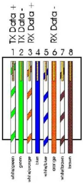
bar
| Category | Value | |---|---| | TX Data + | 1 | | TX Data - | 2 | | RX Data + | 3 | | RX Data - | 4 | | Whitegreen | 5 | | green | 6 | | white/orange | 7 | | blue | 8 | | white/buy | 5 | | orange | 6 | | white/brown | 7 | | brown | 8 || RJ-45 Pin | Signal | Wire Color | RJ-45 Pin |
| 1 | TX+ | White-Green | 1 |
| 2 | TX+ | Green | 2 |
| 3 | RX+ | White-Orange | 3 |
| 4 | Not used | Blue | 4 |
| 5 | Not used | White-Blue | 5 |
| 6 | RX- | Orange | 6 |
| 7 | Not used | White-Brown | 7 |
| 8 | Not used | Brown | 8 |
B&B SMARTWORX TECHNICAL SUPPORT
Phone: 1-800-346-3119
(Monday - Friday, 7 a.m. to 5:30 p.m. CST)
Fax: 815-433-5109
Email: support@bb-smartworx.com
Web: www-bb-smartworx.com