
PI8463 - Oven Smev - Free user manual and instructions
Find the device manual for free PI8463 Smev in PDF.


| Product Type | Gas Oven (Built-in for Recreational Vehicles and Marine) |
| Brand | Smev |
| Model | PI8463 |
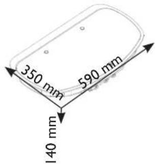
| Dimensions (Width x Height x Depth) | 572 mm x 350 mm x 590 mm |
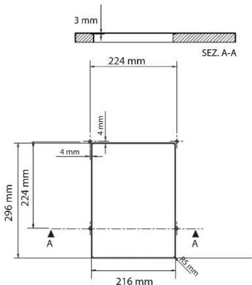
| Fitting Cavity Dimensions | See manual figure 5 (varies by model; typically 560 mm width x 140 mm height x 590 mm depth for this series) |
| Gas Type | Universal LPG (Propane/Butane) |
| Gas Pressure (Regulator Output) | 2.75 kPa, 2.5 kg/h |
| Gas Connection | 1/4 BSPT female (rigid metal pipe required) |
| Electrical Supply (Ignition/Light) | 12 V ---, protected by 3 A fuse (polarity sensitive) |
| Ignition | Electronic (pushbutton) or manual (match/lighter) |
| Oven Features | Thermostatic control (1-6 positions, 130°C-240°C), flame failure safety device, oven door safety switch, separate grill burner |
| Grill | Gas grill burner, must be used with door open and heat guard extended; max 25 minutes |
| Hotplate (if included) | Gas burners (auxiliary, semi-rapid, rapid) with electronic/manual ignition; optional electric hotplate on some models |
| Spit / Turntable | Available on some models (accessories); motor operated via dedicated switch |
| Material | Stainless steel and enameled parts |
| Cleaning Instructions | Use water and neutral soap; avoid abrasives, chlorine, steel wool; clean burner caps and heads regularly |
| Safety Warnings | Do not obstruct ventilation; keep children away; use only in well-ventilated areas; do not store flammable materials nearby |
| Installation Requirement | Must be installed by authorized person; comply with local gas and electrical regulations; cavity must be sealed |
| Servicing | Only by authorized personnel; annual service recommended |
| Included Manual Languages | English (original); other languages available upon request via email |
Frequently Asked Questions - PI8463 Smev
User questions about PI8463 Smev
0 question about this device. Answer the ones you know or ask your own.
Ask a new question about this device
Download the instructions for your Oven in PDF format for free! Find your manual PI8463 - Smev and take your electronic device back in hand. On this page are published all the documents necessary for the use of your device. PI8463 by Smev.
USER MANUAL PI8463 Smev
Built-in Hotplate, Ovens, Stoves, Minigrills,
Hotplate-Sink Combos for Recreational Vehicles and Marine.
Models: CU311 - CU31IM - CU333 - CU333M - CU335 -
CU335M - CU40I - CU40IPE - CU402 - CU402PE
- CU403 - CU403PE - FO311 - MO8103 - MO8123
PI09I3 - PI09I3A - PI8002 - PI8022 - PI8003 - PI8023
- PI8403 - PI8403GL - PI8423 - PI8423GL - PI8443 -
PI8463 - PI862IA - PI862IS - PI862IR - VN555
Installation, use and service manual
CONTENTS
I GENERAL INFORMATION......3
I.1 Symbols used in this manual....3
1.2 Using and keeping the manual ....3
2. WARNINGS .... 4
3. USE....5
3.1 Precautions....5
3.2 Control panel....5
3.3 Hotplate....6
3.3.1 Selecting the burner 6
3.3.2 Electronic ignition hotplate (depending on model)....7
3.3.3 Manual ignition hotplate....7
3.3.4 Hotplate flame regulation 7
3.4 Oven 7
3.4.1 Electronic ignition oven....8
3.4.2 Manual ignition oven....8
3.4.3 Oven flame regulation with thermostat 8
3.5 Grill 8
3.5.1 Electronic ignition grill 9
3.5.2 Manual ignition grill....9
3.5.3 Flame regulation grill....9
3.6 Electric hotplate (depending on model) 10
3.7 Spit (depending on model)....10
3.8 Turntable (depending on model)....10
3.9 Cleaning 10
3.10 Abnormal Operation....II
4. INSTALLATION......12
4.1 Dimensions of the appliance....12
4.2 Fitting cavity 12
4.3 Gas connection 12
4.4 Electric connection....14
4.5 Fixture 15
4.6 Testing (before leaving)....15
4.6.1 Test point.... 16
4.7 Duplicate data plate....16
5 SERVICING....17
FIGURES AND TECHNICAL DRAWINGS....19-32
WHO TO CONTACT 36
I GENERAL INFORMATION
I.1 Symbols used in this manual
Below are shown the various symbols used in the manual to highlight particularly important information. The safety symbols draw attention to potential hazards for personal safety.
Absolutely respect all safety messages by following these symbols.
WARNING
Risk of injury or death.
WARNING

CAUTION
To avoid possible injuries and/or malfunctions.
CAUTION
I.2 Using and keeping the manual
WARNING
Always read the instructions provided in full before installing and using this appliance.
WARNING
The aim of this manual is to supply all the information necessary to ensure that, as well as being used correctly, the appliance can be managed in the safest and most autonomous way possible.
Keep this manual and all the attached documentation in good condition, legible and complete in all its parts; it is forbidden to remove, rewrite or modify the pages of the manual and their content in any way.
Keep the documentation near the appliance, in an accessible place known to all users.
The manual must always accompany the appliance even in the event of sale and must therefore be handed over to the new user.
2. WARNINGS
Do not use or store flammable materials in the appliance storage drawer or near this appliance.
Do not spray aerosols in the vicinity of this appliance while it is in operation.
Do not modify this appliance.
Where this appliance is installed in marine craft or in caravans, it shall NOT be used as a space heater.
This appliance shall be installed only by authorised persons and in accordance with the manufacturer's installation instructions, local gas fitting regulations, municipal building codes, electrical wiring regulations, AS 5601-2004 - Gas Installations and any other statutory regulations.
This appliance must be used only in a well ventilated environment. Do not obstruct the flow of combustion and ventilation air.
This appliance is designed and manufactured for cooking food only. Any other use is considered improper and incorrect creating hazardous conditions. The manufacturer declines all responsibility for damage to things or injuries to persons caused by incorrect installation and / or incorrect and improper use.
If the appliance is to be left unused for any length of time, it is recommended that the gas supply be turned off at the cylinder or main supply valve feeding the appliance.
3. USE
3.1 Precautions

CAUTION
CAUTION
The appliance must only be used by responsible adults. During use and immediately after use the burner and other accessible parts may be hot; do not touch these parts and always keep children at a safe distance. After using the appliance ensure the knob/knobs are off.
After use always shut off the gas supply at the main gas tap.

WARNING
WARNING
This appliance must not be used by persons (including children) who suffer from psychical and motor related disorders or who are not familiar with or who have no experience with the appliance unless under supervision or are being instructed on how to use the appliance by the person responsible for their safety. Children must always be supervised to prevent them from playing with the appliance.

WARNING
WARNING
WARNING
of gas appliances generates heat and moisture in the immediate area. Always ensure a good ventilation in the cooking area: keep all air vents open for natural ventilation or install an extractor fan (cookerhood).
WARNING
An intense and prolonged use of the appliance may require additional ventilation, for example opening a window, or increasing the power of any mechanical extraction system.

CAUTION
CAUTION
Before cooking with the oven and grill for the first time turn on the oven or grill at high flame and leave the oven on for at least 30 minutes and the grill for 15-20 minutes.
Before opening the glass cover of the hotplate, remove any liquids that may have spilled.
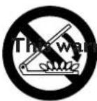
WARNING
The warning is affixed in a visible location on the hotplate glass lid. Glass hotplate lids may shatter when heated. Always raise the lid before igniting a burner/s (hotplate, oven and grill) and turn off all burners (hotplate, oven and grill) and let them cool down before lowering the hotplate glass lid.
3.2 Control panel
The following symbols identify which knob corresponds to which burner.
NOTE: Different models could have similar knobs and symbols.

This symbol is positioned near the burner knobs on the hotplate.
black dot indicates the position of the burner on the hotplate.

This symbol is positioned near the oven burner knob.

This symbol is positioned near the grill burner knob.
The following symbols are for burner flame regulation and correspond to the position of the knob.
NOTE: Different models could have similar knobs and symbols.
Gas off

High flame

Low flame
0 Electric hotplate off
1 - 2 - 3 - 4 - 5 - 6 Oven and/or electric hotplate temperature

Grill
OTHER SYMBOLS
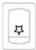
Electronic ignition pushbutton
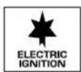

CAUTION
This symbol is affixed in a clearly visible position near the oven control knob for all models fitted with electronic ignition which is activated by maintaining the control knob pressed.
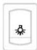
Light switch

Spit switch

Turntable switch
In CU4... models it is also present as a turntable and light.
3.3 Hotplate
3.3.1 Selecting the burner

WARNING
The flame must never extend beyond the edge of the pan. Centre the pan over the burner ensuring stability on the pan support.
WARNING
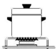
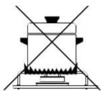
| Burner | Pan diameter |
| Min Max | |
| Auxiliary 47 mm | 6 cm 16 cm |
| Semi-rapid 62 mm | 16 cm 22 cm |
| Rapid 77 mm | 16 cm 22 cm |
3.3.2 Electronic ignition hotplate (depending on model)

WARNING
Make sure there are no pans or any other objects on the burners when igniting.
WARNING
To ignite the burner, gently push in and turn the control knob to position HIGH FLAME and, keeping the knob pushed in, at the same time press the electronic ignition pushbutton. Once the burner is lit, keep the knob pushed in for a few seconds to ensure the flame remains lit.

CAUTION
If the burner does not ignite immediately repeat ignition after having followed each step below:
CAUTION
• Turn the knob to "Low flame"
• Proceed with manual ignition
- Check there is sufficient gas in the gas bottle.
If the appliance still does not ignite shut off the gas supply at the main gas tap and contact your local dealer.
3.3.3 Manual ignition hotplate
Manual ignition when the appliance is not fitted with the electronic ignition feature or in the event of failure in the electronic ignition.

WARNING
Make sure there are no pans or any other objects on the burners when igniting.
WARNING
To ignite the burner, gently push in and turn the control knob to position HIGH FLAME and, keeping the knob pushed in, at the same time light the burner with a match or gas lighter. Once the burner is lit, keep the knob pushed in for a few seconds to ensure the flame remains lit.

CAUTION
If the burner does not ignite immediately, check there is sufficient gas in the gas bottle.
CAUTION If the appliance still does not ignite, shut off the gas supply at the main gas tap and contact your local dealer.
3.3.4 Hotplate flame regulation
To regulate the flame turn the knob to the desired cooking flame.
3.4 Oven

CAUTION
The oven burner must be ignited only with the oven door fully open.
CAUTION
WARNING
The wire shelf, drip tray and oven dish when in the oven must be positioned so as to avoid coming into contact with the flames.
WARNING If the burner flame goes out accidentally, turn off the gas knob and wait one minute before re-igniting.
3.4.1 Electronic ignition oven
To ignite the burner, push in and turn the control knob to a position from 1 to 6 and, keeping the knob pushed in, at the same time press the electronic ignition pushbutton (for models that have affixed to the oven door the electronic ignition button is not visible and is activated by pressing the gas knob down). Once the burner is lit, keep the knob pushed in for a few seconds to ensure the flame remains lit.

CAUTION
If the burner does not ignite immediately, repeat ignition after having followed each step below:
CAUTION • proceed with manual ignition
- check there is sufficient gas in the gas bottle.
If the appliance still does not ignite, shut off the gas supply at the main gas tap and contact your local dealer.
3.4.2 Manual ignition oven
Manual ignition when the appliance is not fitted with the electronic ignition feature or in the event of failure in the electronic ignition.
To ignite the burner, gently push in and turn the control knob to a position from 1 to 6 and, keeping the knob pushed in, at the same time light the burner with a match or gas lighter. Once the burner is lit, keep the knob pushed in for a few seconds to ensure the flame remains lit.

CAUTION
If the burner does not ignite immediately, check there is sufficient gas in the gas bottle.
If the appliance still does not ignite, shut off the gas supply at the main gas tap and contact your local dealer.
3.4.3 Oven flame regulation with thermostat
| Positions | | 2 | 3 | 4 | 5 | 6 | |
| Temperature |3 | 0ircC 160ircC | 180ircC 200ircC | 220ircC 240ircC |
When the oven burner is ignited the flame remains at high flame in all knob positions. When the oven reaches the set temperature the flame automatically goes down to low flame.
3.5 Grill
CAUTION
The grill burner must be ignited only with the door fully open.
CAUTION

WARNING
WARNING
As accessible parts may be very hot when using the grill, keep children at a safe distance from grill.
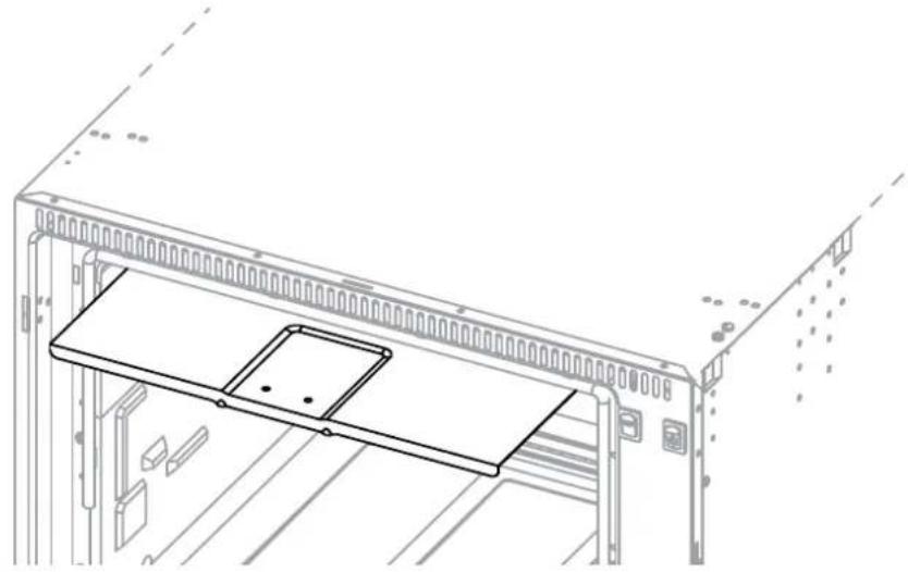
When using the grill the door must be kept open and with the heat guard fully extracted (FIG. I - PG. 19).
Never use the grill for more than 25 minutes. The grill cannot be used as an oven. If the burner flame goes out accidentally, turn off the gas knob and wait one minute before re-igniting.
3.5.1 Electronic ignition grill
WARNING
Do not ignite the grill burner with the door closed.
WARNING
To ignite the burner, gently push in and turn the control knob to position GRILL or HIGH FLAME and, keeping the knob pushed in, at the same time press the electronic ignition button (for models with the ★ symbol affixed to the door, the ignition button is not visible and is activated by pressing the knob down). Once the burner is lit, keep the knob pushed in for a few seconds to ensure the flame remains lit.
CAUTION
If the burner does not ignite immediately, repeat ignition after having followed each step below:
CAUTION
• proceed with manual ignition
- check there is sufficient gas in the gas bottle.
If the appliance still does not ignite, shut off the gas supply at the main gas tap and contact your local dealer.
3.5.2 Manual ignition grill
Manual ignition when the appliance is not fitted with the electronic ignition feature or in the event of failure in the electronic ignition.
To ignite the burner, gently push in and turn the control knob to position GRILL or HIGH FLAME and, keeping the knob pushed in, at the same time light the burner with a match or gas lighter. Once the burner is lit, keep the knob pushed in for a few seconds to ensure the flame remains lit.

CAUTION
If the burner does not ignite immediately, check there is sufficient gas in the gas bottle.
CAUTION If the appliance still does not ignite, shut off the gas supply at the main gas tap and contact your local dealer.
3.5.3 Flame regulation grill
For models CU311 - CU31IM - CU333 - CU333M - CU335 - CU335M - FO311:
the grill is to be used only at its maximum capacity.
For all other models:
to regulate flame, turn the knob to the desired cooking flame.
3.6 Electric hotplate (depending on model)

CAUTION
CAUTION
Before turning on the electric hotplate (or if the hotplate has remained unused for a long time) it is necessary to eliminate any moisture by turning on the hotplate and leaving it on for 30 minutes with the corresponding knob in position I.
Use pans with flat bottoms and with diameters no less than the diameter of the hotplate.
Dry the bottom of the pan before placing it on top of the hotplate.
When using the hotplate do not leave the appliance unattended and make sure children are nowhere near the appliance.
The electric hotplate is controlled by a 7-position knob: position off is 0 (zero) whereas positions 1 to 6 are for regulating the hotplate. Positions 1 to 6 correspond to an increase in temperature of the hotplate. There is a red LED positioned next to the knob which lights up when the hotplate is on.
3.7 Spit (depending on model)
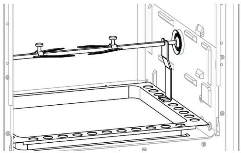
Ignite the oven as described in the chapter 3.4 Oven. Turn the gas knob to the required position. Insert the drip tray with the spit already installed as illustrated in FIG. 2 - PG. 19. Press the spit button to turn on the spit motor.
3.8 Turntable (depending on model)
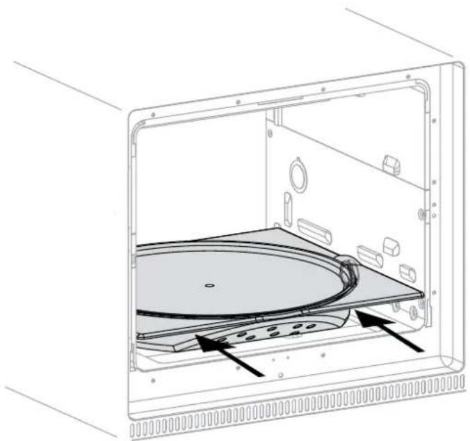
Ignite the oven burner as indicated in chapter 3.4 Oven. Insert the turntable as indicated in FIG. 3 - PG. 19 Press the switch to operate the turntable motor.
3.9 Cleaning
No regular maintenance is required except cleaning.

WARNING
WARNING
Some cooking operations generate a considerable amount of grease. This, combined with spillage, can become a hazard if allowed to accumulate on the appliance through lack of cleaning.

CAUTION
CAUTION
Keep the appliance clean and in good working condition. To clean below the hotplate
burners, remove the burner cap screws using a suitable screwdriver. Once the screws are removed, the burner cap and burner head can be removed to provide access below the burner. Once cleaned, ensure the burner head and burner cap are refitted. It is recommended to have it serviced annually by authorized personnel.

WARNING
WARNING
Before cleaning the appliance always turn it off and disconnect from power supply and wait until it has cooled down.

CAUTION
CAUTION
Hou surfaces may be damaged on contact with cold water or with a wet cloth. Do not use abrasive, corrosive or chlorine-based products, pot scourers or steel wool. Do not leave acid or alkaline substances (vinegar, salt, lemon juice, etc.) on the surfaces of the appliance. Stainless steel surfaces and enamelled parts must be washed with water and neutral soap or detergent, rinsed and dried. Use clean sponges and cloths.

WARNING
WARNING
Never use abrasive and / or coarse cleaning materials or metal brushes to clean the glass oven door as these materials scratch the glass surface with the risk of shattering the glass.

WARNING
WARNING
CAUTION
e steam cleaners to clean the appliance.

CAUTION
CAUTION
The trivet (pan support) can be removed by carefully pulling the extended pins evenly out of the plastic locaters in the hotplate. When replacing the trivet, ensure that the plastic guides are not damaged.
3.10 Abnormal Operation
Gas valves, which are difficult to turn are considered to be abnormal operation and may require servicing. In case the appliance fails to operate correctly, contact the authorised service provider in your area.
4.1 Dimensions of the appliance
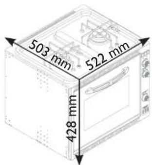
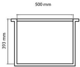
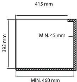
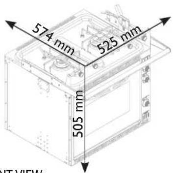
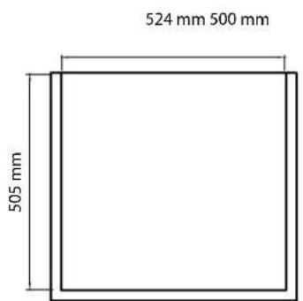
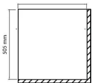
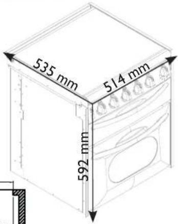
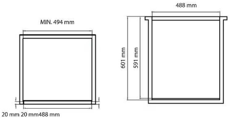
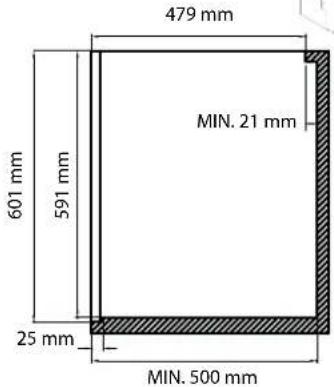
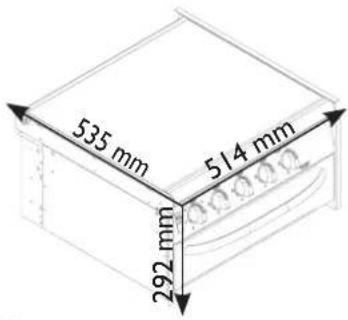
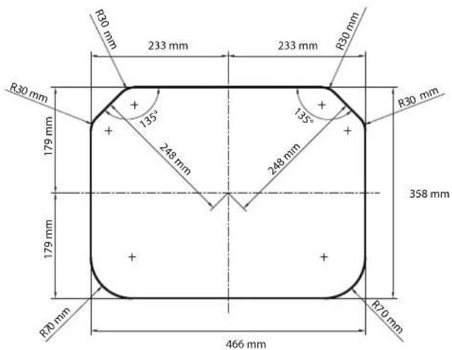
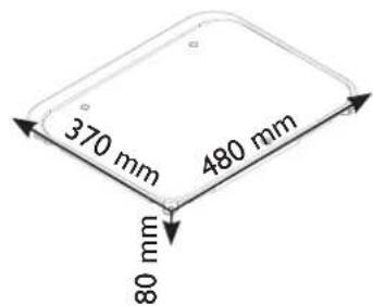
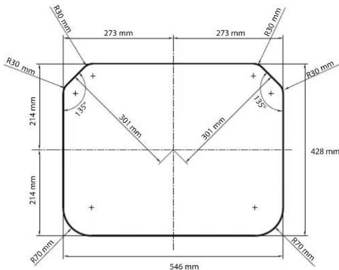
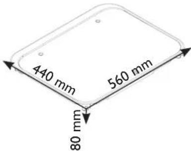
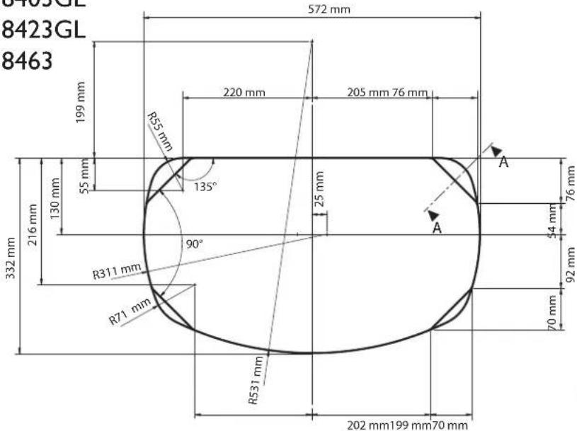
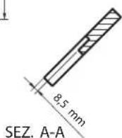
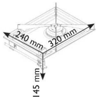
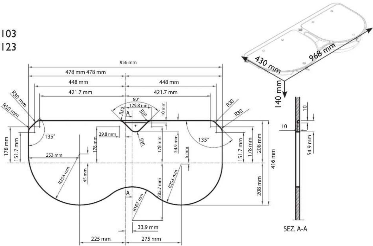
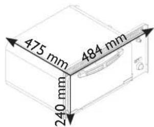
The overall dimensions are illustrated in FIG. 5 - PG. 21 with the cavity diagrams.
The overall dimensions include the trivet (pan support), control knobs, handles and gas connection.
4.2 Fitting cavity

WARNING
The appliance must fitted at an appropriate and safe distance from flammable materials.

WARNING
CU..., FO... and VN555 models, the cavity that the appliance is built into must be completely sealed off. It is important that the inside panels of the cavity are completely sealed and do not communicate with adjoining cavities or the outside. The openings in the cavity that allow access to the gas and electric connections should be sealed with rubber or foam.
The gas connection (I/4 BSPT female) is located at the rear for models CU..., FO... and for model VN555, whereas it is on the bottom for models PI... and MO...
The electric connection is located at the rear for models CU..., FO... and for model VN555, whereas it is on the bottom for models PI... and MO... (consult chapter 4.4 Electric connection to see whether the appliance needs this connection).
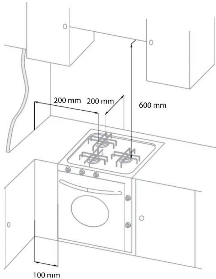
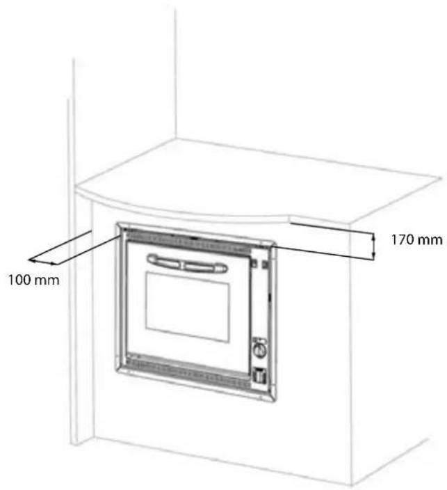
Minimum allowable distances from walls (FIG. 4 - PG. 20)
| 200 mm From | the external edge of the burner head nearest to a side and / or back wall. |
| 600 mm Between | en the top part of the burners and cabinets and / or shelves fitted above the hotplate. |
| 100 mm From | the sides of the appliance and vertical walls. |
| 170 mm From | the top side to the cabinets and / or shelves fitted above the appliance. |
Dimensions of fitting cavity
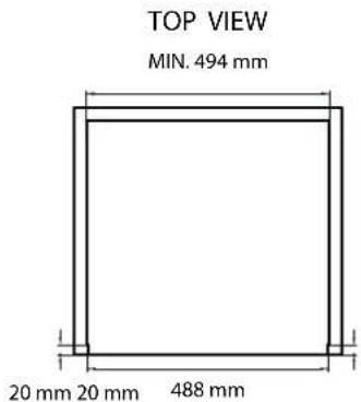
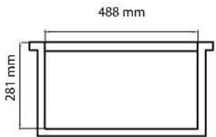
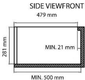
Cut out a hole in the cabinet as illustrated in FIG. 5 - PG. 21 size will depend on appliance model.
The cabinet must be appropriately constructed and aligned horizontally with the worktop and with the unit.
The cabinet aperture must be perfectly squared and aligned. If there are apertures for cabinet ventilation, prevent flammable materials from entering these.
4.3 Gas connection

WARNING
This appliance shall be installed only by authorised persons and in accordance with
the manufacturer's installation instructions, local gas fitting regulations, municipal building codes, electrical wiring regulations, AS 5601-2004 - Gas Installations and any other statutory regulations.

WARNING
ance is not connected to a flue terminal which discharges the product of
combustion to the outside. Any enclosed space in which the appliance is installed must therefore be provided with permanent ventilation in accordance with relevant federal and state regulations in force, and the requirements of gas installations with particular attention being paid to the matter of room ventilation.
WARNING
WARNING
WARNING
liance is not suitable for connection with a hose assembly.
Below are the gas characteristics for which the appliance is set (given also on the appliance data plate). A pressure reducer suitable for the type of gas used must be connected between the gas cylinder and the appliance:
| GAS PRESSURE OUTPUT OF THE REGULATOR | ||
| UNIVERSAL LPG | 2,75 kPa 2,5kg/h | |
The connection of the gas pipe to the appliance (1/4 BSPT female) must be made with a rigid metal pipe. The pipe work and fittings shall be free from defects and of an approved type.
Once installed, the installation must be checked for leaks by means of an approved testing method.
Do not use a solution of soap and water.

WARNING
WARNING
Never use a naked flame to check for gas leaks.
4.4 Electric connection
Low voltage 12V ---
This chapter concerns only models marked 12V --- on the appliance data plate.

CAUTION
CAUTION
This appliance must be connected to a 12V --- source. The circuit must be protected by a fuse of no more than 3 Ampere.
Ensure that the polarity of the connection is correct!

WARNING
WARNING
Absolutely do not connect the appliance to the mains voltage (230 V\~), this would destroy the components and cause a hazard for the user.
To connect the appliance use a 1.5 mm 2 double red and black wire and wire to the terminal junction box located at the rear of the appliance with the wording "+12 V---". The red terminal is the positive pole and the black terminal is the negative pole.
High voltage 230-240 V\~
This chapter refers only to the models listed in the table below.
| Model Nominal voltage | Nominal power | |
| CU401PE - CU402PE - CU403PE | 230-240V~800W |
In these models there is an electric plate in the hotplate.
WARNING
WARNING
connecting direct to the mains supply, it is necessary to install a circuit breaker which allows for disconnecting and isolating the appliance from the mains in the event of overvoltage III conforming to installation regulations.
The supply cord must be positioned in such a way that it never reaches a temperature of 75irc C above ambient in any point.
The plug must be easy to access after installation.
Always disconnect electrical power before working on or servicing the appliance.
For connecting to the mains power supply use a socket.
If the supply cord (H05RR-F 3x0,75mm 2 ) is damaged, it must be replaced by the manufacturer or its service agent or a similarly qualified person in order to avoid a hazard.
4.5 Fixture

CAUTION
CAUTION
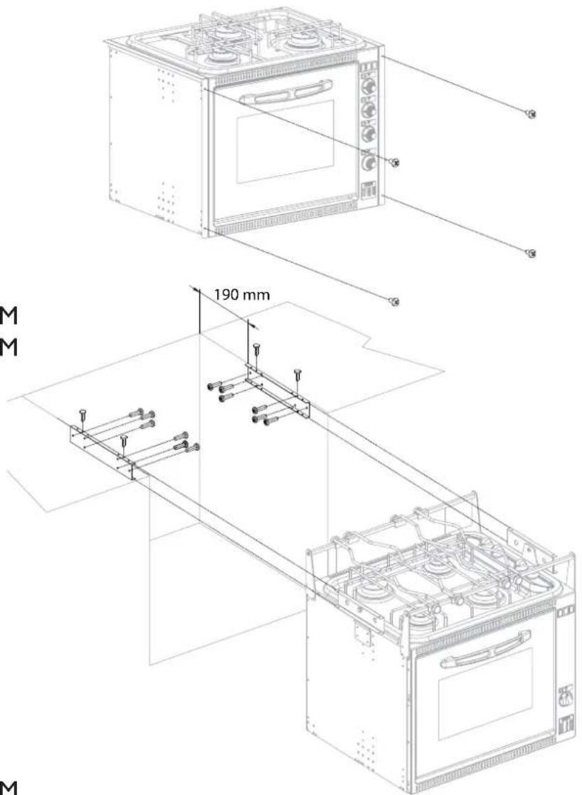
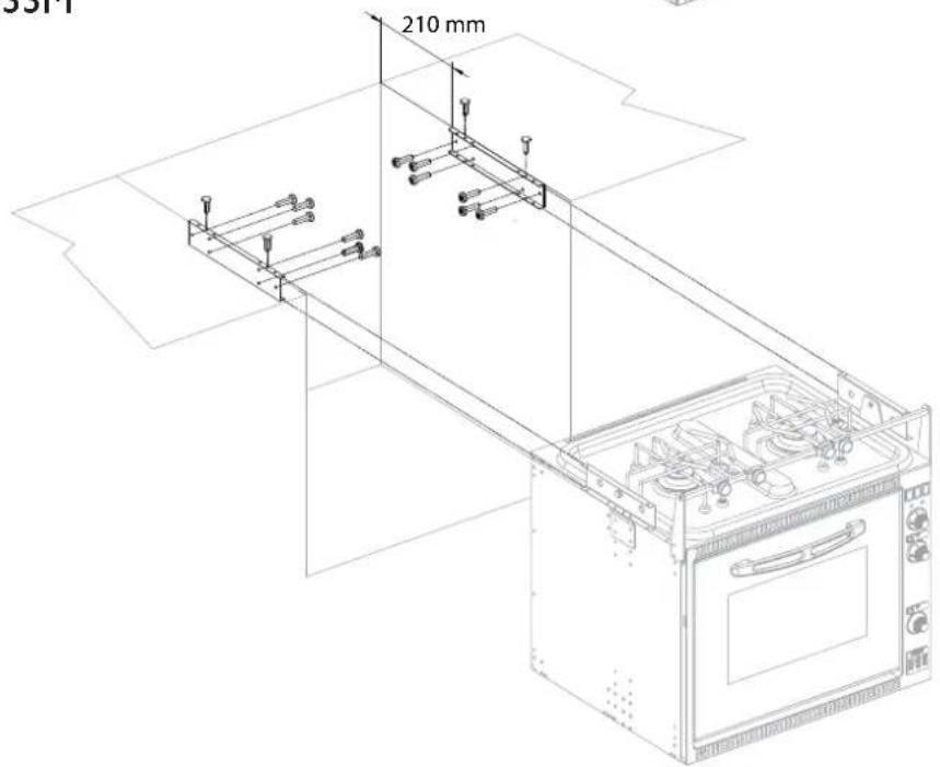
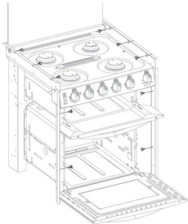
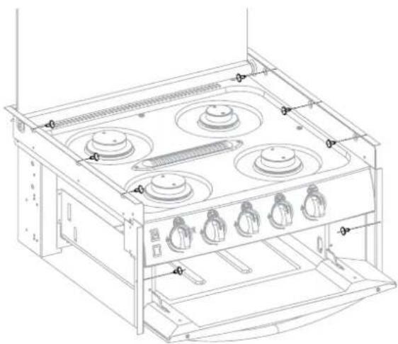
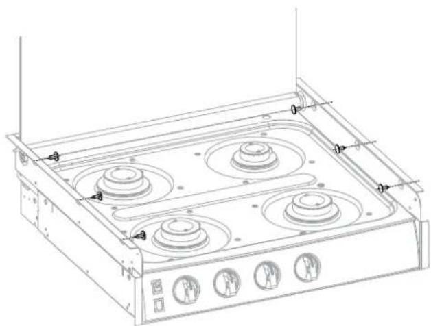
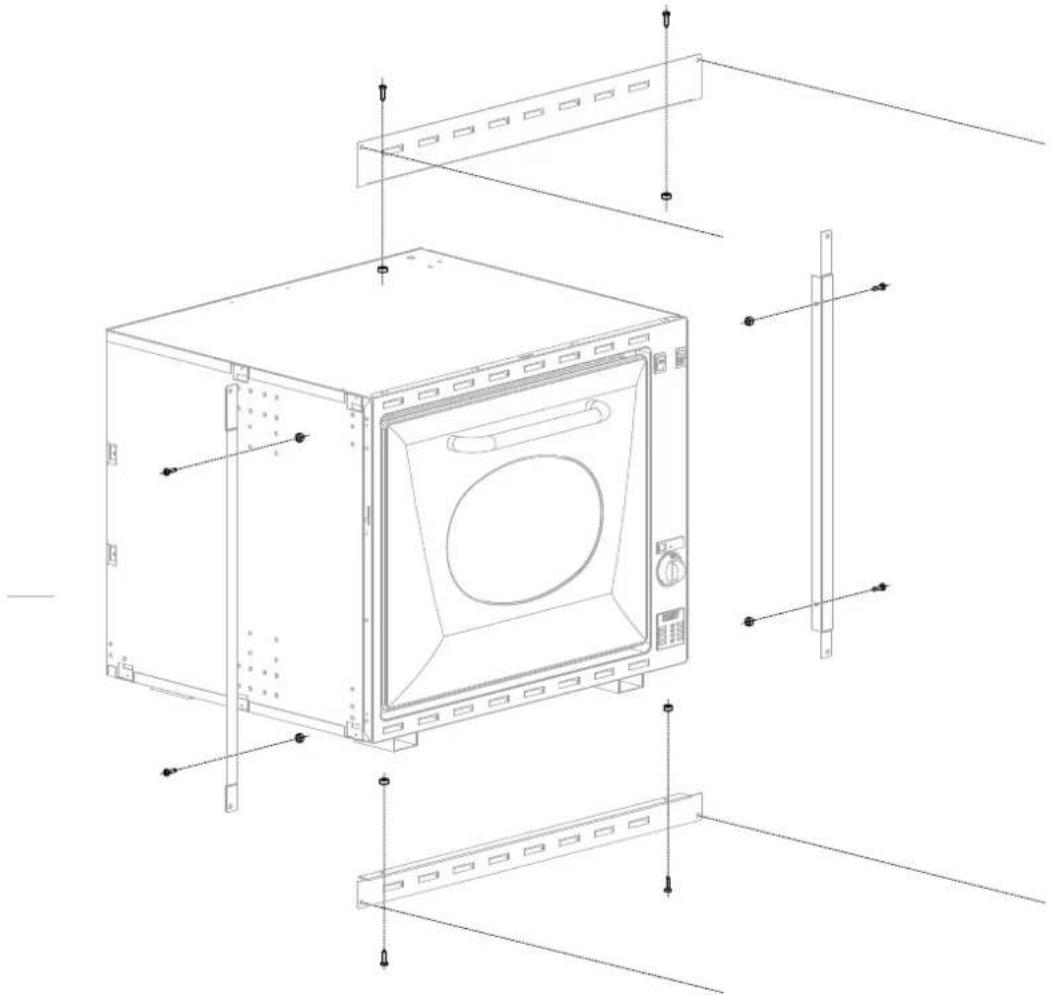
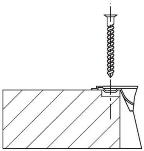
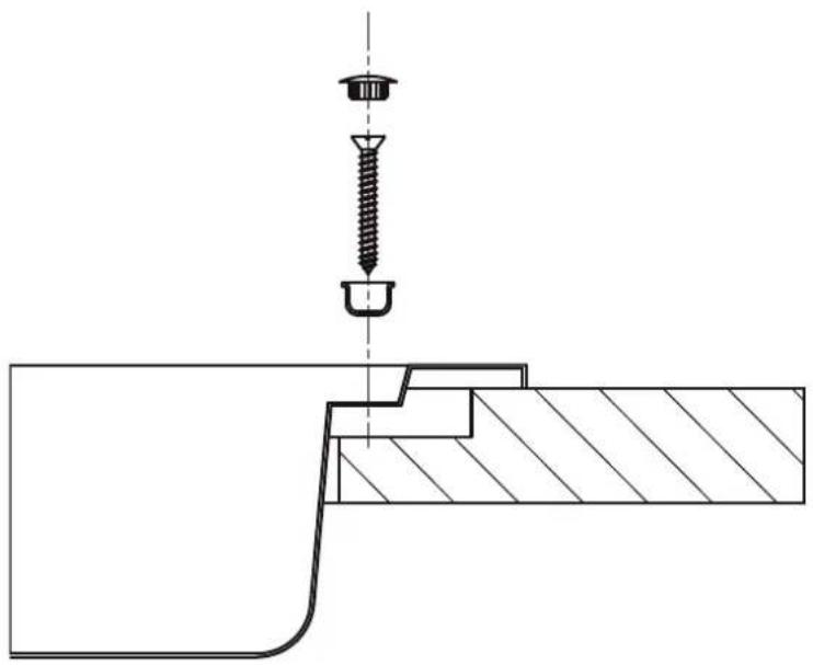
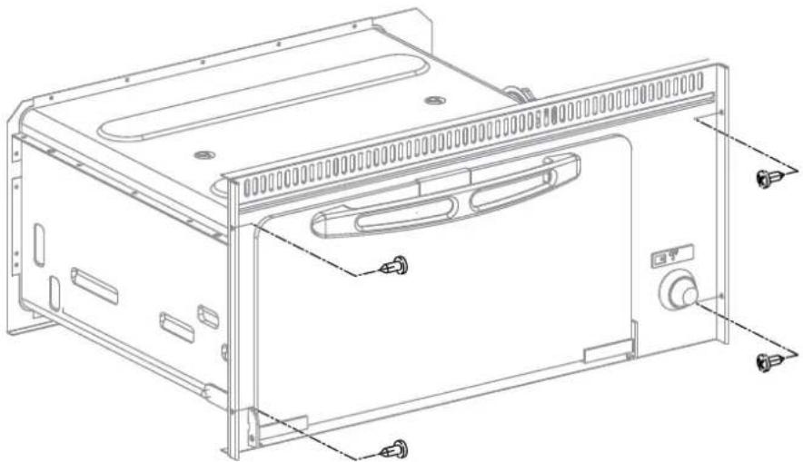
oppliance is to be fixed and secured to the cabinet as described in FIG. 6 – PG. 26.
4.6 Testing (before leaving)
Ignite all burners both individually and concurrently to ensure correct operation of gas valves, burners and ignition. Turn gas taps to low flame position and observe stability of the flame for each burner individually and concurrently. Ensure correct operation of the flame failure protection.
Depending on the type of gas used, the appearance of the flame is as follows:
Propane: flame with blue centre and well-defined contour.
Butane: flame with light yellow tips when igniting the burner, gradually intensifying as the burner heats.
CAUTION
CAUTION
The appliance fails to operate correctly after all checks have been carried out, shut off the gas supply at the main gas tap and refer to the authorized service provider in your area.
When satisfied with the appliance, please instruct the user on the correct method of operation.
4.6.1 Test point
For models PI... MO... CU...
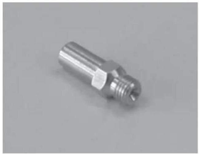
The test point is supplied loose with the appliance (see picture in FIG. 7 - PG. 31). Remove one burner head, the injector and screw in test point fitting. The pressure is measured with the relevant burner gas valve on high flame and with an inlet pressure of 2.75 kPa.
For models FO...
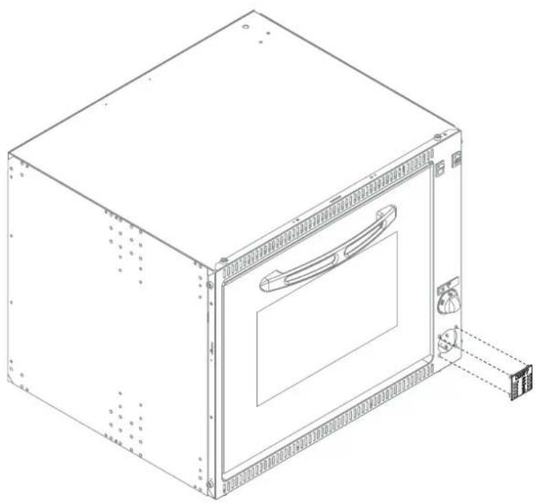
The test point is fitted on the main gas pipe. Remove the front plastic plaque (see picture in FIG. 8 - PG. 31) and remove the screw. The pressure is measured with an inlet pressure of 2.75 kPa.
For models VN555
The test point is fitted on the main gas pipe. Remove the screw. The pressure is measured with an inlet pressure of 2.75 kPa.
4.7 Duplicate data plate
After installation, the data plate may be consulted by opening the door of the oven or of the grill compartments, or on the back of the instructions manual.
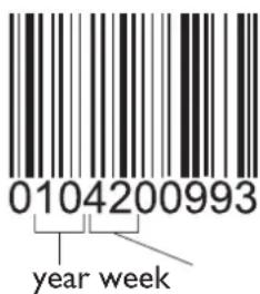
The date of manufacture can be deduced from the serial number: the 2nd and the 3rd figure indicate the year, the 4th and the 5th figure the week. See the example below.
5 SERVICING

WARNING
WARNING
- vicing shall be carried out only by authorized personnel.
WARNING
WARNING
modify this appliance.
WARNING
any servicing intervention shut off gas supply, disconnect all the electrical power supplies and remove the appliance.
WARNING
Hotplate: burners, injectors, thermocouples and ceramic igniters
I. Remove trivet (pan support) by pulling up from hotplate.
2. Remove screws from appropriate burner head disk. Remove head disk.
3. Remove burner by lifting straight up, taking care not to damage the thermocouple and ceramic igniter.
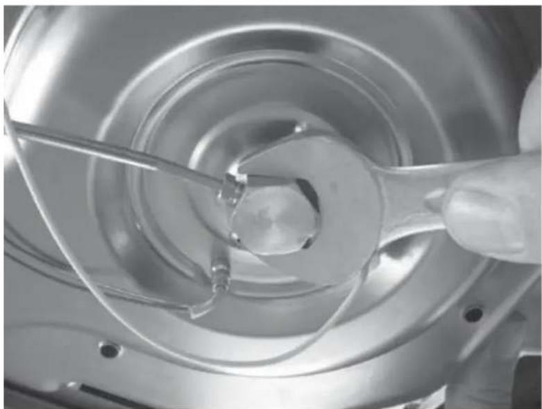
4. Using a 7mm spanner, unscrew the injector. When removing and fitting the injector, the injector holder must be held in place with the aid of a tool (FIG. 9 - PG. 32)
5. Remove retaining washer from thermocouple head.
6. Disconnect appropriate thermocouple lead from gas cock.
7. Remove the thermocouple.
8. Remove retaining spring from ceramic igniter head.
9. Disconnect appropriate ceramic igniter lead from electronic igniter unit.
10. Remove the ceramic igniter.
II. Replace/ refit in reverse procedure.
Oven: injector, burner, thermocouple and ceramic igniter
I. From right hand side of appliance, remove spring from the oven burner inlet.
2. Using a 7mm spanner, unscrew the injector. When removing and fitting the injector, the injector holder must be held in place with the aid of tool (FIG. 9 - PG. 32).
3. Remove lower heat shield at rear and tilt appliance forward.
4. Unscrew the oven burner mounts and lower burner.
5. Remove retaining nut from thermocouple head.
6. Disconnect the oven thermocouple lead from the gas cock.
7. Remove the thermocouple.
8. Remove retaining screw from ceramic igniter support.
9. Disconnect ceramic igniter lead from appropriate electronic igniter unit.
10. Remove the ceramic igniter.
II. Replace/ refit in reverse procedure.
Grill: injector, thermocouple, ceramic igniter and burner
I. From right hand side of appliance, remove spring from the grill burner inlet.
2. Using a 7mm spanner, unscrew the injector. When removing and fitting the injector, the injector holder must be held in place with the aid of tool (FIG. 9 - PG. 32)
3. Remove the protection disk (not present in the CU4... models)
4. Remove retaining nut from thermocouple head.
5. Disconnect the grill thermocouple lead from the gas cock
6. Remove the thermocouple.
7. Remove retaining screw from ceramic igniter support.
8. Disconnect ceramic igniter lead from appropriate electronic igniter unit.
-
Remove the ceramic igniter.
-
Remove the grill burner mounting screws (2) from top.
II. Remove the grill burner mounting spacers (only for CU4... models) and lower burner.
Gas cocks
I. Remove the control knob by pulling.
2. Unscrew gas cock retaining nut.
3. From the underside of the appliance, remove the thermocouple lead and the gas pipe from the gas cock.
4. Remove the appropriate gas cock clamp by unscrewing the screws.
5. Remove the gas cock from the manifold.
6. Replace/ refit in reverse procedure.
Oven thermostat
I. Remove the appropriate control knob by pulling.
2. Unscrew gas cock retaining nut.
3. From the underside of the appliance, remove the thermocouple lead and the gas pipe from the thermostat.
4. Remove the thermostat clamp by unscrewing the screws.
5. Remove the thermostat from the manifold.
6. Open oven door and remove the capillary bulb/ phial from its mount.
7. Remove capillary bulb/ phial though access hole.
8. Replace/ refit in reverse procedure.
Igniter unit/s
I. From the rear right-hand side of appliance, remove electrical connectors from igniter unit/s (noting connection locations).
2. Remove the retaining rivets from appropriate igniter unit.
3. Remove the igniter unit.
4. Replace / refit in reverse procedure.
Oven door
I. Open oven door fully.
2. Remove the door hinge screws (2 each) at either side of the bottom of oven compartment.
3. Remove door from appliance.
4. Replace/ refit in reverse procedure.
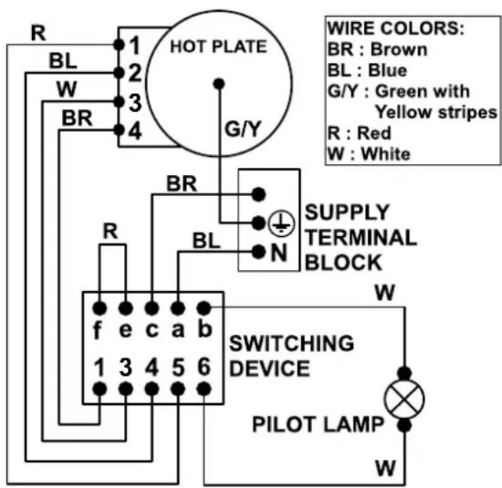
230-240V\~WIRING DIAGRAM
Shown below is the wiring diagram for the 230-240 V\~ connection for a stove with electric element on the hotplate.
FIGURES AND TECHNICAL DRAWINGS
Figure I
natural_image
Technical line drawing of a server rack with ventilation grilles and a front panel (no text or symbols)Figure 2
natural_image
Technical line drawing of a mechanical assembly with mounting brackets and a pulley (no text or symbols)Figure 3
natural_image
Technical line drawing of a microwave oven with internal components and mounting holes (no text or symbols)Figure 4
CU311 - CU311M - CU333 - CU333M
- CU335 - CU335M - CU401 -
CU401PE - CU402 - CU402PE
- CU403 - CU403PE - MO8103 -
MO8123 - PI0913 - PI0913A - PI8002
- PI8022 - PI8003 - PI8023 - PI8403 -
PI8403GL - PI8423 - PI8423GL - PI8443
- PI8463 - PI862IA - PI862IS - PI862IR
FO311 - VN555
Figure 5
CU311 CU333 CU335
SIDE VIEWFRONT VIEW
CU31IM CU333M CU335M
SIDE VIEWFRONT VIEW
CU40I CU40IPE
TOP VIEW SIDE VIEWFRONT VIEW
CU402 CU402PE
CU403 CU403PE
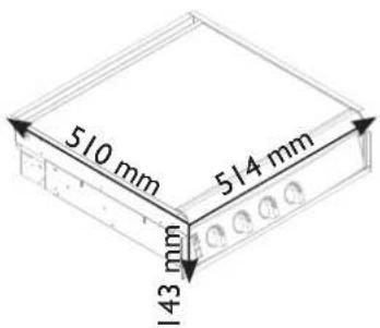

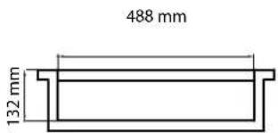
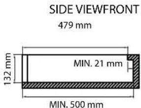
FO311
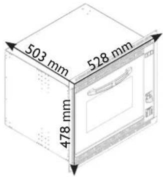
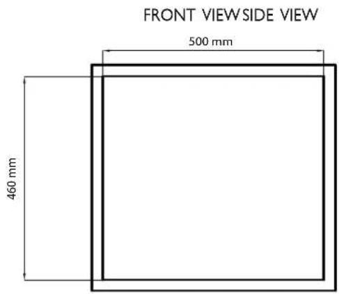
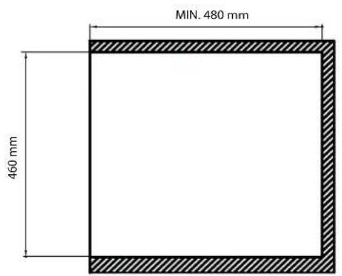
PI0913 PI0913A
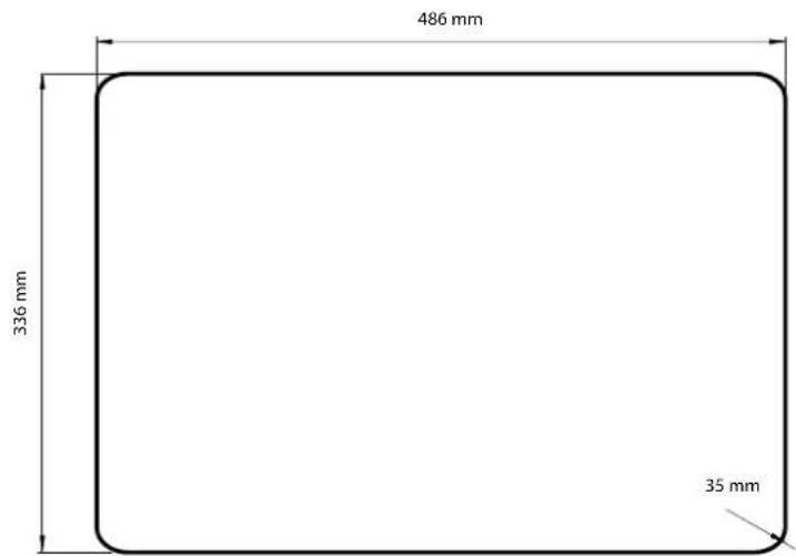
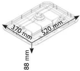
PI8002 PI8022
PI8003
PI8023
PI8403 - PI8403GL
PI8423 - PI8423GL
PI8443 - PI8463
PI8621A
PI8621R
PI8621S
MO8103
MO8123
VN555
FRONT VIEWSIDE VIEW
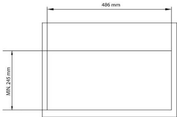
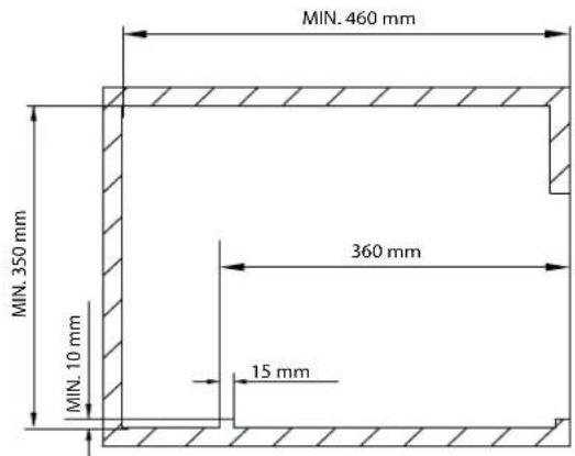
Figure 6
CU311 CU333 CU335
CU311M
CU335M
CU333M
CU40I CU40IPE
natural_image
Technical line drawing of an oven with multiple gas outlets and control knobs (no text or labels)CU402 CU402PE
natural_image
Technical line drawing of a portable stove or oven with four fans and control knobs (no text or labels)CU403 CU403PE
FO311
natural_image
Technical line drawing of a microwave oven with internal components and mounting brackets (no text or labels)PI0913
PI0913A
PI8621A
PI8621R
PI8621S
natural_image
Technical line drawing of a screw fastening process with no text or symbolsPI8002
PI8022
PI8003
PI8023
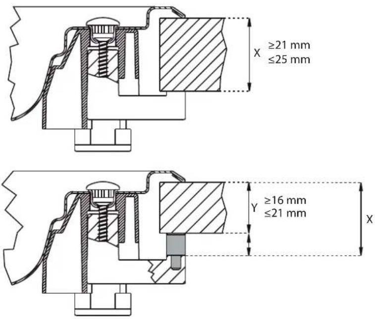
PI8403 - PI8403GL
PI8423 - PI8423GL
PI8443 - PI8463
natural_image
Technical drawing of a mechanical assembly with a screw and pin, showing cross-section and hatching (no text or symbols)MO8103 MO8123
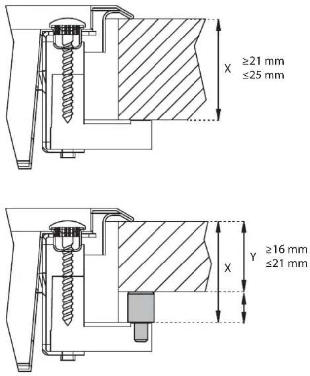
VN555
natural_image
Technical line drawing of a computer tower case with mounting brackets and ventilation slots (no text or symbols)Figure 7
natural_image
Metal mechanical component with threaded end and hexagonal top (no visible text or symbols)Figure 8
natural_image
Technical line drawing of a rectangular electronic device with internal components and mounting bracket (no text or symbols)Figure 9
natural_image
Close-up of a hand holding a wrench inside a metallic mechanical component (no visible text or symbols)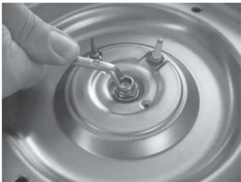
natural_image
Close-up of a hand holding a wrench over a circular mechanical component (no visible text or symbols)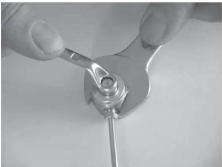
natural_image
Close-up of hands using a wrench to adjust a mechanical component (no text or symbols visible)Notes
WHO TO CONTACT
For service of your appliance, firstly contact your selling agent.
Australia
Dometic Australia, Queensland I
I John Duncan Court
Varsity Lakes QLD 4227
phone: +61 (0)7 5507 6000
fax: +61 (0)7 5507 6001
e-mail: sales@dometic-waeco.com.au
web: www.dometic-waeco.com.au
Dometic Australia, Victoria
Bldg 3B, Clayton Business Park
1508 Centre Rd, Clayton VIC 3168
phone: +61 (0)3 9239 1000
fax: +61 (0)3 9239 1099
e-mail: sales@dometic-waeco.com.au
web: www.dometic-waeco.com.au
Dometic Australia, Queensland 2
2/129 South Pine Road
Brendale QLD 4500
phone: +61 (0)7 3205 7599
fax: +61 (0)7 3881 1405
e-mail: sales@dometic-waeco.com.au
web: www.dometic-waeco.com.au
Dometic Australia, Western Australia
12 Prosperity Ave,
Wangara WA 6065
phone: +61 (0)8 9209 3033
fax: +61 (0)8 9209 3577
e-mail: sales@dometic-waeco.com.au
web: www.dometic-waeco.com.au
New Zealand
Dometic New Zealand Limited, Auckland
Unit 15, 180 Montgomerie Road
Airport Oaks, Auckland 1701
phone: +64 (0)9 256 0018
fax: +64 (0)9 256 0017
e-mail: sales2@dometic.co.nz
web: www.dometic.co.nz
Dometic New Zealand Limited, Wellington
26 Cashew Street
Grenada North, Wellington 6440
phone: +64 (0)4 232 3898
fax: +64 (0)4 232 3878
e-mail: customerservices@dometic.co.nz
web: www.dometic.co.nz
- Built-in Hotplate, Ovens, Stoves, Minigrills,
- Hotplate-Sink Combos for Recreational Vehicles and Marine.
- CONTENTS
- I GENERAL INFORMATION......3
- WARNINGS .... 4
- USE....5
- INSTALLATION......12
- SERVICING....17
- FIGURES AND TECHNICAL DRAWINGS....19-32
- WHO TO CONTACT 36
- I GENERAL INFORMATION
- I.1 Symbols used in this manual
- I.2 Using and keeping the manual
- WARNINGS
- USE
- Precautions
- CAUTION
- WARNING
- Control panel
- OTHER SYMBOLS
- Hotplate
- Selecting the burner
- Electronic ignition hotplate (depending on model)
- Manual ignition hotplate
- Hotplate flame regulation
- Oven
- Electronic ignition oven
- Manual ignition oven
- Oven flame regulation with thermostat
- Grill
- Electronic ignition grill
- Manual ignition grill
- Flame regulation grill
- Electric hotplate (depending on model)
- Spit (depending on model)
- Turntable (depending on model)
- Cleaning
- Abnormal Operation
- Dimensions of the appliance
- Fitting cavity
- Dimensions of fitting cavity
- Gas connection
- Electric connection
- High voltage 230-240 V\~
- Fixture
- Testing (before leaving)
- Test point
- For models PI... MO... CU...
- For models FO...
- For models VN555
- Duplicate data plate
- SERVICING
- Hotplate: burners, injectors, thermocouples and ceramic igniters
- Oven: injector, burner, thermocouple and ceramic igniter
- Grill: injector, thermocouple, ceramic igniter and burner
- Gas cocks
- Oven thermostat
- Igniter unit/s
- Oven door
- 230-240V\~WIRING DIAGRAM
- FIGURES AND TECHNICAL DRAWINGS
- Notes
- WHO TO CONTACT
- Australia
- Dometic Australia, Queensland I
- Dometic Australia, Victoria
- Dometic Australia, Queensland 2
- Dometic Australia, Western Australia
- New Zealand
- Dometic New Zealand Limited, Auckland
- Dometic New Zealand Limited, Wellington
Brand : Smev
Model : PI8463
Category : Oven