
TKASVAL114WW - Security Camera JUNG - Free user manual and instructions
Find the device manual for free TKASVAL114WW JUNG in PDF.


| Product Type | Video Outdoor Station (Security Camera) |
| Brand | JUNG |
| Model | TKASVAL114WW (1 to 4-gang) |
| Front Plate Dimensions (W x H x D) | 178.5 x 226 x 4 mm |
| Flush Mount Box Dimensions (W x H x D) | 134 x 183 x 40 mm |
| Labeling Field (W x H) | 71 x 85 mm |
| Supply Voltage | +24 V DC ±8% (from power supply and control unit) |
| Input Current (idle) | I(a) = 0.1 mA, I(P) = 26 mA |
| Max Input Current | I(amax) = 14 mA, I(Pmax) = 150 mA |
| Protection Rating | IP44 (according to DIN EN 50486) |
| Admissible Ambient Temperature | -20 °C to +50 °C |
| Operating Humidity | 0 to 80% r.h. |
| Camera Resolution | 1.3 MP |
| Detection Angle | 130° |
| Audio | Full duplex with AEC (acoustic echo cancellation), active noise suppression |
| Video Features | Automatic day/night switch, backlight compensation, white fader |
| Material | Break-proof camera cover, metal faceplate, stainless steel flush mount housing |
| Wiring | 6-wire technique (a, b, P, M, V1, V2) |
| Cleaning | Dry or slightly moist cloth; no aggressive or abrasive cleaners |
| Safety | Installation by qualified electrician only; observe VDE 0100 and VDE 0800 |
| Spare Parts / Repairability | Replaceable EEPROM board, bell button covers, nameplate foil; service center available |
| General Information | Hands-free operation, programmable bell buttons, light switching, fault indication via LED and tones |
Frequently Asked Questions - TKASVAL114WW JUNG
User questions about TKASVAL114WW JUNG
0 question about this device. Answer the ones you know or ask your own.
Ask a new question about this device
Download the instructions for your Security Camera in PDF format for free! Find your manual TKASVAL114WW - JUNG and take your electronic device back in hand. On this page are published all the documents necessary for the use of your device. TKASVAL114WW by JUNG.
USER MANUAL TKASVAL114WW JUNG
DCM Video outdoor station
1 to 4-gang
TK ASV AL 114 WW
TK ASV AL 114
TK ASV ES 114
2 to 8-gang
TK ASV AL 128 WW
TK ASV AL 128
TK ASV ES 128
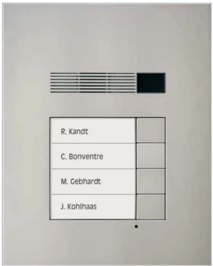
Table of content
Safety instructions....3
Application / Brief description....4
Application....4
Brief description....4
Device overview....5
Wiring and installation....6
Wiring example 6-wire technique ....6
Connecting diagram 7
Possible connection for a door release relay....7
Installation....7
Commissioning 10
Acoustic and optical signals, pressing buttons 10
Setting the button layout ....11
Bell button programming....13
Basic principle 13
Programming a bell button 13
Programming a second indoor station to a bell button (parallel call)....14
Deleting the programming 16
Parameters 17
Settable parameters....17
Setting and blocking AS-address 17
Setting and cancelling a programming block....17
Light switching function 17
Automatic light switching 17
Light switching....17
Nameplate illumination 17
Setting parameters with DIP switches 18
Labelling the nameplate....20
Fault identification, indication and querying 20
Fault sources....20
Explanation of terms and definitions ....21
General notes on the wiring in DCM video systems 22
6-wire operation....22
Cleaning....23
Technical data 24
Acceptance of guarantee....24
Safety instructions
Assembly, installation, and commissioning must only be carried out by a qualified electrician!
For work on systems with 230 V AC mains current the safety requirements of DIN VDE 0100 must be observed.
When installing DCM BUS systems the general safety rules for telecommunication systems in accordance with VDE 0800 must be observed:
- separate cabling for high and low voltage lines
- minimum distance of 10 cm for joint cabling arrangements,
- use of separators between high and low voltage lines in joint cable ducts,
- use of standard telecommunication cables, e. g. J-Y (St) Y with 0.8 mm ^2 cross section
- existing cables (modernisation) with different cross sections may be used whilst taking account of the loop resistance.

Suitable lightning prediction must ensure that a voltage of 32 V DC will not be exceeded at the DCM BUS wires a and b.
Application / Brief description
Application
- hands-free operation with high audio quality (full duplex)
- release door calls
- Start a video image at the video indoor station by means of pressing a bell button
- switching light
Brief description
- Camera with a resolution of 1.3 MP, detected area of 130^ , automatic screen adjustment, automatic switch over between day and night, automatic backlight compensation, automatic white fader, camera cover made of break-proof material
- full duplex operation in combination with comfort indoor station
- half duplex operation in combination with standard indoor station
- high audio quality due to active noise suppression (noise and line echo cancellation)
- AEC (Acoustic Echo Cancellation), electronic method for acoustic echo reduction
• automatic calibration of the ambient and network conditions
• high-quality sound and great speaker dynamics
• volume adjustable
• covers for push-buttons can be combined variably, 1- to 4-gang or 2- to 8-gang - acknowledge tone for bell button
- acoustic status indication if system is occupied (existing communication)
• automatic call cut-off
• durable energy saving LEDs for labelling illumination - fault analysis due to different flashing of the LED labelling illumination
- fault differentiation due to acoustic feedback signal when pressing a bell button
- weather-proof loudspeaker
• solid, robust metal faceplate - stainless steel flush mounted housing, adjustable installation frame
- integrated dismounting protection
- bell button configured for switching light (basic settings)
- bell button switches light depending on brightness (automatic light)
• brightness threshold adjustable - programming possible without access to flats
- connection: 6-wire-technique
• electret capacitor microphone - audio and video stations can be combined in the same installation
- inscription fields can be labelled with the JUNG labelling tool (www.jung-label.de)
Device overview
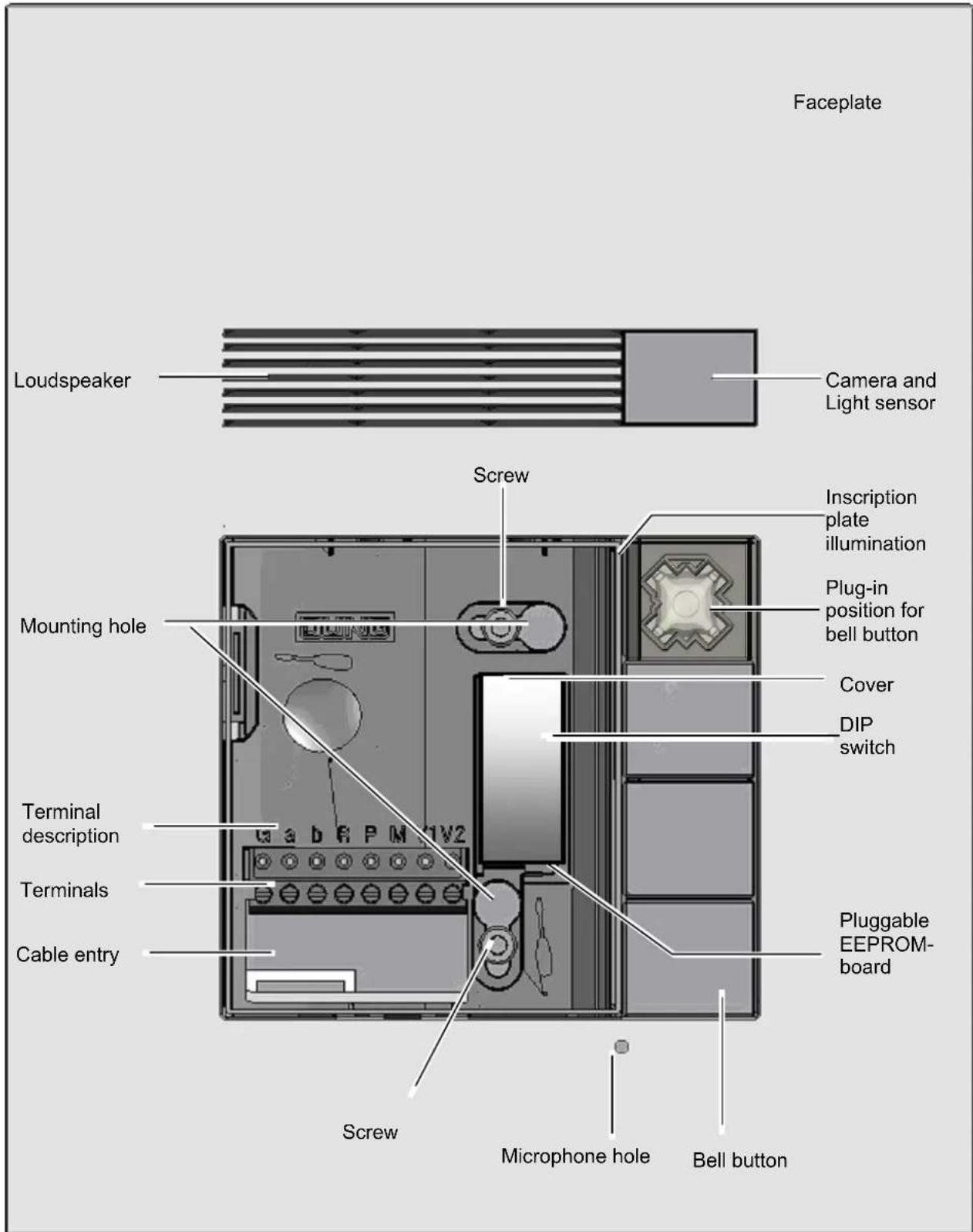
Fig: TK ASV AL 114, without inscription plate
Wiring and installation
Wiring example 6-wire technique
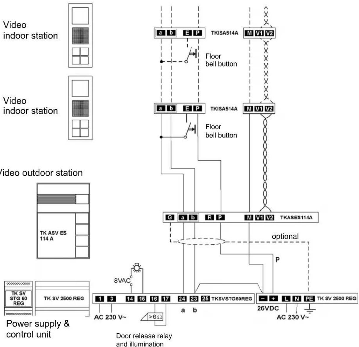
The power supply units TK SV STG 60 REG + TK SV 2500 REG enable the connection of 8 indoor station + 8 parallel connected indoor station. Observe maximum output current!
flowchart
graph TD
    A["Video indoor station"] --> B["TKISA514A"]
    C["Video indoor station"] --> D["TKISA514A"]
    E["Video outdoor station"] --> F["G a b R P M V1 V2 TKASES114A"]
    G["Power supply & control unit"] --> H["AC 230 V~ 8VAC"]
    H --> I["Door release relay and illumination"]
    I --> J["AC 230 V~ >6Ω"]
    K["Floor bell button"] --> L["Ground"]
    M["Floor bell button"] --> N["Ground"]
    O["optional"] --> P["P"]
    Q["26VDC"] --> R["AC 230 V~"]
    S["AC 230 V~"] --> T["Ground"]
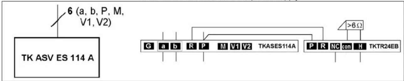
Connecting diagram Possible connection for a door release relay
Please use door release relay TK TR 24 EB.
Floating relay contact:
Max. AC 24 V, 2 A of external power supply
Installation
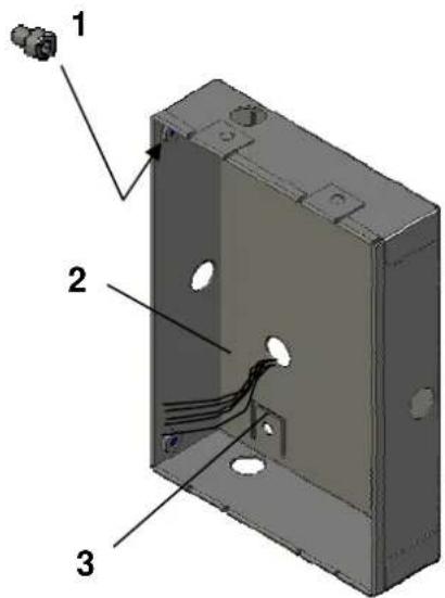
Flush mounted housing
- Fasten the 4 delivered short hexagon screws (1) with a hexagon key.
- Shut the unused cable entry holes with the delivered dummy plug.
- Put the wires through the selected cable entry hole (2).
- Connect the flush mounted housing into the wall. The edge of the housing has to be flush with the wall surface to enable, that the faceplate of the outdoor station fits flat on the wall.
Connection possibilities:
- Connect the strap (3) of the housing with screws to the wall.
- Attach with plaster by means of using plaster straps (4 metal sheets with holes, 4 screws and 4 nuts). These plaster straps can be connected on the reverse side of the housing to the housing straps (3).
Flush mounted housing
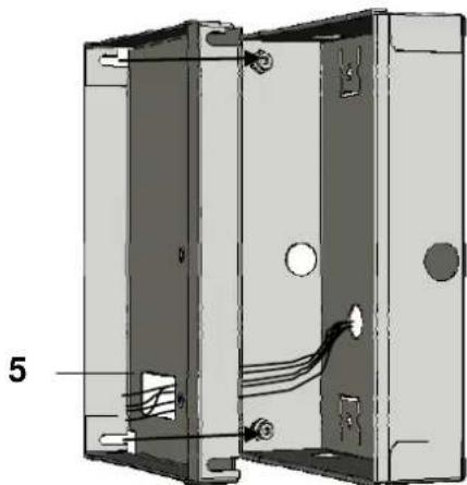
Installation frame
The wall is plastered and the housing is installed flush with the plaster into the wall.
- Unscrew the 4 hexagon screws until they stick out half length.
- Put the wires through the cable entry hole of the installation frame (5).
- Put the installation frame into the housing in that way, that the slots of the frame fit behind the screw heads.
- Press the installation frame into the flush mounted housing and tighten the hexagon screws.
natural_image
Technical diagram of an electrical enclosure with internal wiring and mounting holes (no text or symbols)Installation frame
| Install faceplatePut the wires through the cable entry of the faceplate.Fasten the device with the delivered screws (1) and (2) into the installation frame.Put the bell button covers onto the plug-in position as required. Observe the top and bottom edge of the cover.Do not pinch the wires.First tighten the upper screw (1) after this the lower screw (2). | 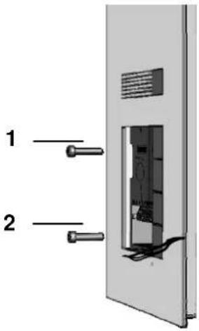 |
| Connect the wiresTake off the connection block downwards.Attach the wires to the connection block in accordance with the terminal description.Plug on the connection block.Place the wires into the space under the connection block.Protruding wires disturb the installation of the inscription plate. | 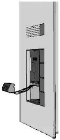 Terminal descriptionI Terminal descriptionI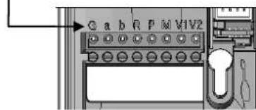 |
| Carry out the following steps before closing the device:commissioningcover configurationprogrammingadjusting parameterlabelling the inscription plate | |
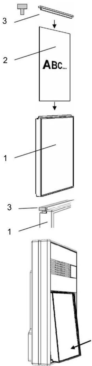
Inscription field
- Put the labelled inscription foil (2) into the inscription field (1).
1 inscription field
2 inscription foil
3 gasket
- Close the opening with the gasket (3).
Pay attention of the gasket position.
Closing the device
- Put the nameplate with the upper edge into the housing and snap the bottom edge into place.
- The name plate should snap into place with a click.
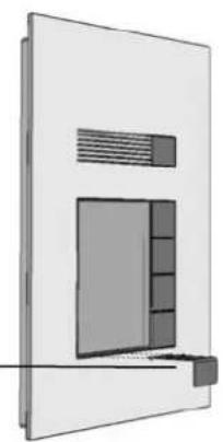
Opening the device
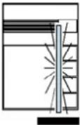
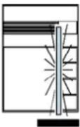
- Slide the opening tool into the slit under the nameplate until it engages.
- Pull the opening tool out of the device together with the nameplate.
Opening tool
natural_image
Pure architectural diagram of a modern wall-mounted cabinet or enclosure with no text, numbers, or symbolsCommissioning
| ! |  Please complete the full installation before you connect the system to the mains voltage!Do NOT connect V1 and V2 with the P-, M-, a- or b-wire. Even a connection for a quick moment will destroy the device.When connecting the video wires V1 (+) and V2 (-) observe polarity.If you can see a distorted image on the display, switch off the mains voltage and change the wires V1 and V2.. Please complete the full installation before you connect the system to the mains voltage!Do NOT connect V1 and V2 with the P-, M-, a- or b-wire. Even a connection for a quick moment will destroy the device.When connecting the video wires V1 (+) and V2 (-) observe polarity.If you can see a distorted image on the display, switch off the mains voltage and change the wires V1 and V2.. |
• Install all of the devices of the system completely.
- Check the a, b and P wires for short-circuit.
- Switch on the mains voltage.
The following functions are available without additional programming:
- communication from the indoor stations to the outdoor station
- door release function
- light switching
Acoustic and optical signals, pressing buttons
| Positive acknowledge tone | 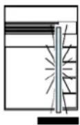 | Nameplate illumination On | ||
| Negative acknowledge tone (button already programmed) | ||||
| Ring tone (from programming acknowledgement) | ||||
| Prog2 tone (programming of the 2nd serial number begins) | 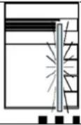 | Nameplate illumination flashes: Programming mode0.5 s On / 0.5 s Off | ||
| NoProg tone (programming will be deleted if the button is released now) | ||||
| ProgBlock tone | 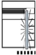 | Nameplate illumination flashes quickly: Parameter mode0.125 s On / 0.125 s Off | ||
| Occupied tone | ||||
| Press button briefly (approx. 1s) and release | 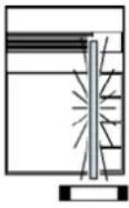 | Nameplate illumination pulse flashing: Fault mode0.175 s On / 0.825 s Off | ||
| Press button until ... | ||||
| Release button |
Setting the button layout
The button layout can be configured using the DIP switch.
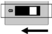
To set the button layout, DIP switch 8 must be in the OFF position.
! If the button layout is not set for 1-gang and 2-gang buttons, there will be malfunctions during operation.
When the button layout is changed, all of the bell buttons have to be deleted. All bell buttons are assigned with the light switching function.
DIP switch cover
- Open the device if necessary.
- Remove the cover over the DIP switches.
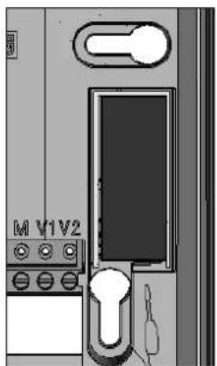
natural_image
Diagram of a computer interface with labeled buttons and a key (no readable text or symbols)Buttons
1-gang button
Button occupies 4 plug-in positions and covers 3 gaps.
2-gang button
Button occupies 2 plug-in positions and covers 1 gap.
4-gang button
Button occupies 1 plug-in position and does not cover any gap.

natural_image
Blank white image with no visible content, text, or symbols1-gang button
2-gang button

4-gang button
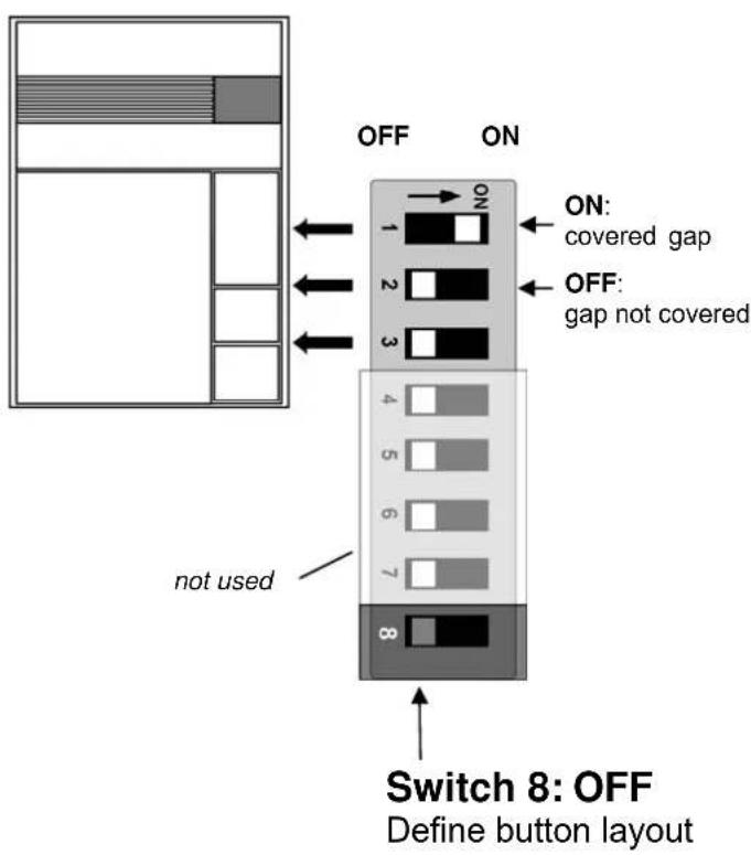
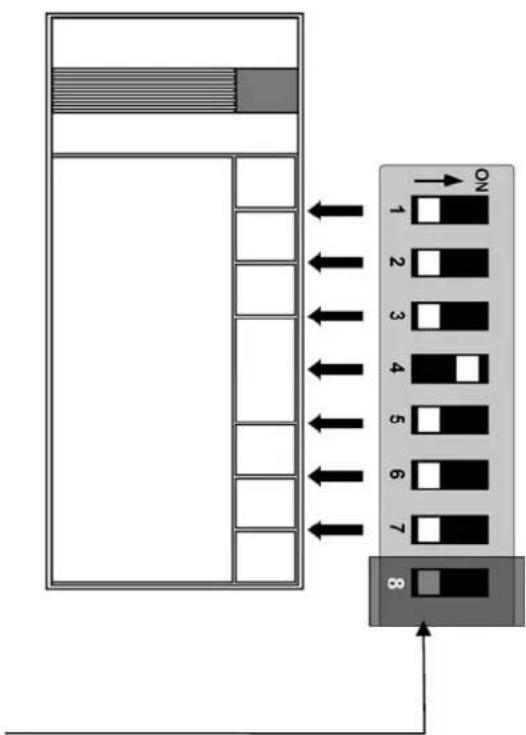
Button layout: Setting the DIP switches
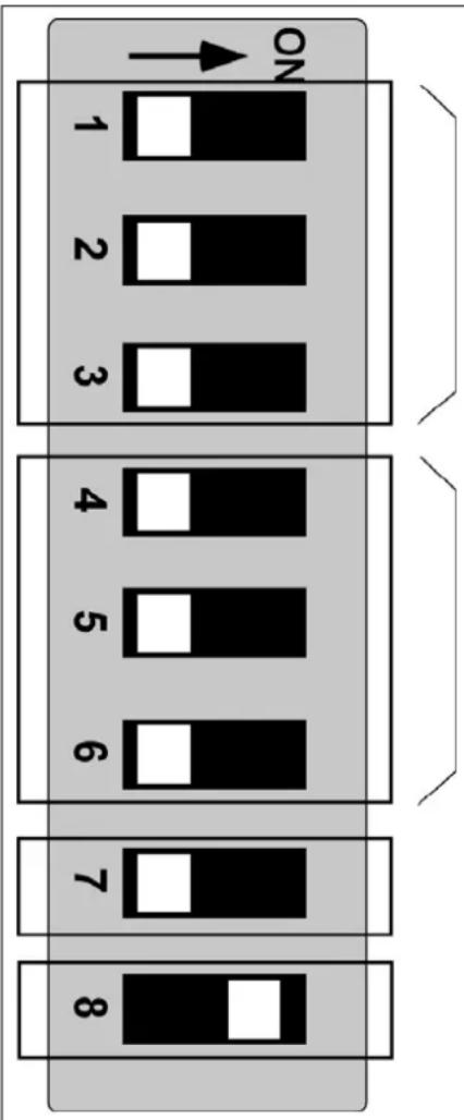
Each DIP switch corresponds to one of the three or seven gaps between two plug-in positions.
If a button covers an gap, the switch must be set to ON.
If configured completely with 4-gang buttons, all DIP switches must be in the OFF position.
flowchart
graph TD
    A["Start"] --> B["Step 1"]
    B --> C["Step 2"]
    C --> D["Step 3"]
    D --> E["Step 4"]
    E --> F["Step 5"]
    F --> G["Step 6"]
    G --> H["Step 7"]
    H --> I["Step 8"]
    I --> J["End"]
    style A fill:#f9f,stroke:#333
    style J fill:#bbf,stroke:#333
Activating the button layout
- To activate the new button layout, the buttons must be programmed as bell buttons (assignment of an indoor station).
- If a 2-gang or 1-gang button is to be used as a light button, this button must first be programmed as a bell button and then deleted.
Fitting the button
- Fit the DCM buttons according to the configuration. Note the mechanical encoding of the buttons. Press lightly on the buttons to snap them in.
Bell button programming
Basic principle
- All of the devices on the DCM BUS have a unique serial number.
- When a bell button is programmed, the serial number of an indoor station is assigned and saved in the EEPROM of the outdoor station. 1 or 2 indoor stations (serial numbers) can be assigned and triggered with each bell button.
- If no serial number is assigned to a bell button (state at delivery / serial number deleted), the light can be switched on by pressing this button.
Programming a bell button
Make sure that the indoor stations are connected to the DCM BUS and the mains voltage is switched on (the LED on the power supply and control unit is illuminated).
!
The button layout must be set before the bell buttons are programmed.
1
The programming must be deleted before a previously programmed bell button can be reprogrammed.
| 1 | Initiation | |
| press briefly LED flashes | Outdoor station in programming mode: flashes, programming mode of the system is switched on | |
| 2a | By means of communication button at the indoor station | |
| Press communication button of the indoor station briefly (communica- tion is established with the outdoor station) | Press button briefly ... positive acknowledge tones sounds at the outdoor and indoor stations 1) | |
1) If instead a programming block tone is audible, the outdoor station has been given a programming block. The programming block can only be cancelled using the commissioning software.
| 2b | By means of floor button (indoor station is not accessible) | ||
| Press floor bell button briefly two times in succession, a ring tone is sounded each time | Press button briefly ... a positive acknowledge tone sounds at the outdoor station and a ring tone sounds at the indoor station | ||
| Repeat steps until all bell buttons have been programmed | |||
| 3 | Finishing | ||
1) If instead a programming block tone is audible, the outdoor station has been given a programming block. The programming block can only be cancelled using the commissioning software.
Programming a second indoor station to a bell button (parallel call)
The parallel call triggers 2 indoor station from one bell button of the outdoor station. The floor button only triggers the hard-wired indoor station.
To give the bell button and floor button the same functionality, the parallel function must be used. In this case several indoor stations respond both to the same bell button and to the same floor button. The parallel function must be set using the commissioning software.
| Note: Repeated programming of an already programmed bell button always only changes the second serial number. If you wish to change the serial number that was programmed first, you have to delete both serial numbers and then reprogram both serial numbers again. | |
| 1 | Initiation |
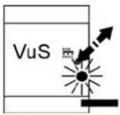 |  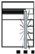 |
| press briefly LED flashes | |
2a By means of communication button at the indoor station
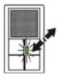
Press communication button of the indoor station briefly (communication is established with the outdoor station)
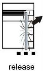
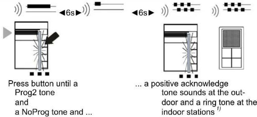
2b By means of floor bell button (indoor station is not accessible)
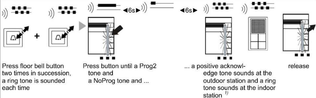
flowchart
graph LR
    A["Press floor bell button"] --> B["+"]
    B --> C["Press button until a Prog2 tone and a NoProg tone and ..."]
    C --> D["... a positive acknowledge tone sounds at the outdoor station and a ring tone sounds at the indoor station 1)"]
    D --> E["release"]
Repeat steps until all ring tones have been programmed
3 Finishing
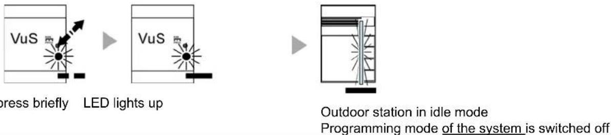
flowchart
graph LR
    A["Press briefly"] --> B["LED lights up"]
    B --> C["Outdoor station in idle mode\nProgramming mode of the system is switched off"]
1) If instead a programming block tone is audible, the outdoor station has been given a programming block. The programming block can only be cancelled using the commissioning software.
Deleting the programming
Before a bell button can be programmed, an existing programming has to be deleted.
| 1 | Initiation | ||
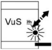 ▶ ▶ 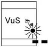 ▶ ▶  press briefly LED flashes Outdoor station in programming mode: flashes, programming mode of the system is switched on press briefly LED flashes Outdoor station in programming mode: flashes, programming mode of the system is switched on | |||
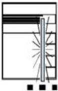
| 2 | Execution | ||
if bell button programmed: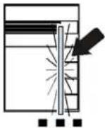  ▶ ▶ 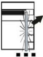 if bell button not programmed:Press until a delete tone sounds after 6 s1) release if bell button not programmed:Press until a delete tone sounds after 6 s1) release | |||
| 3 | Finishing | ||
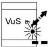 ▶ ▶ 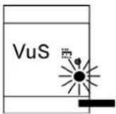 ▶ ▶ 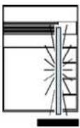 press briefly LED lights up Outdoor station in idle modeProgramming mode of the system is switched off press briefly LED lights up Outdoor station in idle modeProgramming mode of the system is switched off | |||
1) If instead a programming block tone is audible, the outdoor station has been given a programming block. The programming block can only be cancelled using the commissioning software.
Parameters
| Settable parameters | Factory pre-setting | Can be set with DIP switch | Can be set with the commissioning software. |
| AS-address | not | blocked | |
| Communication time 60 s x x | |||
| Door release time 3 s x | |||
| Acknowledge tone type Standard x | |||
| Acknowledge tone volume medium x | |||
| Voice volume | medium x | ||
| Programming block on/off | off | x | |
| Light switching function via the door release function of the indoor stations on/off | off | x | |
| Talking only after incoming door call | off | x | |
| Switching threshold for the automatic light function dependent on outdoor light | medium | x |
Setting and blocking AS-address
For operation with multiple outdoor stations, a separate AS-address (0 - 63) must be set for each outdoor station. This produces an unambiguous assignment of the outdoor stations.
Setting and cancelling a programming block
When a programming block is set, no bell button programming can be performed. The programming block must be reset before reprogramming.
At the same time, when the programming block is cancelled, the light switching function and talking only after incoming door call are cancelled and the acknowledge tone is reset to the factory pre-setting.
Light switching function
Allows double assignment of the door release button to the indoor stations. When the light switching function is activated, door released is only actuated when existing communication is active. Without existing communication the light will be switched on. Thus the function button of the indoor stations remains available for other functions.
Automatic light switching
Brightness-dependent light switching when the bell button is triggered.
The function can be deactivated, adjusted in 6 brightness levels or switched independent of the brightness.
Light switching
The light can be switched on manually via non-programmed bell buttons or the function button of the indoor stations.
In the state of delivery the function button of the indoor station is assigned with this function.
Nameplate illumination
Brightness-independent switching of the nameplate illumination
The state at delivery is always ON.
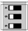
Setting parameters with DIP switches
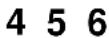
1. Select parameter
Set DIP switches 1, 2 and 3, that the parameter to be changed has been selected.
2. Set value
Set switches 4, 5 and 6 in accordance with the desired value.
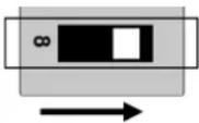
3. Activate parameter mode
Set switch 8 to ON.
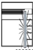
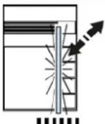
Nameplate illumination flashes quickly (0.125 s On / 0.125 s Off).
4. Apply parameter
Pressing any bell button saves the desired value for the parameter being set. An acknowledge tone sounds as a confirmation.
5. Deactivate parameter mode
Set switch 8 to OFF.
Nameplate illumination: ON.
Note:
To set additional parameters, repeat steps
1 – 5. Otherwise continue with step 6.
6. Set the original button layout
After setting the parameters, reset the DIP switches according to the button layout.
 | 1 2 3 |
 |  |
 |  |
 | |
 |  |
 | |
DIP switch table for parameter setting
| Parameter selection | 1 | 2 | 3 | Parameter |
| OFF | OFF | OFF | Total volume MIC/LSP (Vol) | |
| ON | OFF | OFF | Acknowledge volume (AVo) | |
| OFF | ON | OFF | Door release time (DRt) | |
| ON | ON | OFF | Communication time (Cot) | |
| OFF | OFF | ON | Automatic light switching threshold (ALT) | |
| ON | OFF | ON | Nameplate illumination threshold (NIT) | |
| OFF | ON | ON | not assigned | |
| ON | ON | ON | not assigned |
| Parameter value | 4 | 5 | 6 | Vol | AVo | DRt | Cot | ALT | |
| OFF | OFF | OFF | MIN | MIN | 0.5s | 15s | OFF | ||
| ON | OFF | OFF | 1 | 1 | 1s | 30s | ○ | ○ | |
| OFF | ON | OFF | 2 | 2 | 2s | 45s | 2 | 2 | |
| ON | ON | OFF | 3 | 3 | 3s | 60s | 3 | 3 | |
| OFF | OFF | ON | 4 | 4 | 4s | 75s | 4 | 4 | |
| ON | OFF | ON | 5 | 5 | 5s | 90s | 5 | 5 | |
| OFF | ON | ON | 6 | 6 | 6s | 105s | ☀ | ☀ | |
| ON | ON | ON | MAX | MAX | 7s | 135s | ON | ON | |
| 7 | not assigned |
| 8 | DIP switch function | |
| ON | Set parameter | |
| OFF | Define button layout |
Abbreviations:
Vol Total volume of microphone / loudspeaker
AVo Volume of acknowledge tones
DRt Door release time for a connected door release relay, Art. No.: TKTR24EB
Cot Communication time until the existing communication is switched off automatically
ALT Switching threshold for the automatic light function
NIT Nameplate illumination threshold
Labelling the nameplate
Use the JUNG labelling tool to label the nameplates of your outdoor stations. You will find it at the following Internet address:
www.jung-label.de.
- In the "Template" field, select the ref.-number of your outdoor station, e.g. TK AS AL 114 A WW. Arrange the template to suit your requirements.
- Using a laser printer, print the nameplates on the supplied special foil, Ref. No.: TK 60 FO.
- Insert the foil into the nameplate.
! Use only the supplied foil to label the nameplates! Jung Ref.-No.: TK 60 FO.
Fault identification, indication and querying
- Faults are signalled visually and acoustically (single fault tone and continuous flashing of the light strip).
- The fault type can be queried by pressing any bell button, the fault tone is sounded again.
Fault sources
| Fault sources | Nameplate illumination indication | Fault tone | Elimination |
| No EEPROM |  | 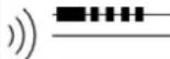 | Insert EEPROM, switch mains voltage on again! |
| a and P wires interchanged | 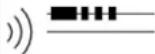 | Exchange a and P wires, device back to idle mode in a few seconds | |
| "a" wire not connected | 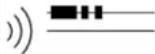 | Connect a wire, device back to idle mode in a few seconds | |
| Button sticks (pressed > approx. 20 s) | Outdoor station in fault mode: flashes |  | Release button, device back to idle mode in a few seconds |
Explanation of terms and definitions
| AS-address | Every outdoor station is assigned with an outdoor station address. The address enables the differentiation between the various installed outdoor station. Selective communication or door release of e.g. main- or side entrance can be realised. |
| Ready for operation | Incoming door call - You can hear a ring tone and the LED at the communication button flashes. You can activate a communication with the outdoor station by means of a short push of the communication button. |
| Hands-free operation (Full duplex) | Simultaneous communication in both directions. |
| Door call | You release a door call at the assigned indoor station by means of pushing the bell button. A bell button can release a door call at two indoor stations (parallel call). |
| Internal call An indoor | station can call another assigned indoor station for an internal communication. |
| Automatic light switching Programming at the outdoor station. | The light will be switched depending on the ambient brightness when you push the bell button of the outdoor station. The limited brightness value is adjustable. |
| Light switching | The function button of the indoor station is assigned with the function "light switching" (factory setting). A bell button of the outdoor station will switch the light, if the bell button is not assigned to an indoor station. |
| Light switching function Programming at the power supply and control unit. | This door release button of the indoor station can be assigned with a second function, when the light switching function is activated: You first have to push the communication button before you can release the door with the door release button. Without pushing the communication button you will switch the light with the door release button. |
| Parallel call A second | indoor station can be programmed to a bell button of the outdoor station. |
| Parallel function | Multiple indoor station can respond to one bell button of the outdoor station or the floor bell button. Each further indoor station respond just as the first indoor station. |
| Programming mode The system has to be in programming mode to assign the indoor stations to the desired bell buttons of the outdoor station. | |
| Programming lock Protection against unauthorized programming. With active programming lock no bell button can be programmed. | |
| Acknowledge tone Acoustical confirmation | |
| Idle mode The device is ready for a door call or other operation. | |
| Call diversion | An incoming door call will be forwarded from one indoor station to another indoor station. The call diversion has to be activated with the function button. The illuminated LED of the function button indicates the activated call diversion. |
| Talking mode A communication between indoor and outdoor station will be activated by means of pushing the communication button. Die LED of the communication button is illuminated.The LED of the communication button is flashing, when another indoor station is already communicating with the outdoor station.After elapsed talking time, activating the door release or pushing the communication button again, the device turns back into idle mode. | |
| Talking only after incoming door call | A communication between indoor and outdoor station can only be activated after an incoming door call. |
| Talking time The communication between indoor and outdoor station will be interrupted after a pre-defined talking time (60 s factory setting). The talking time is adjustable. | |
| Control function Command for the control various relays in the door communication system. | |
| Sub door call | The sub door call enables to assign 4 additional bell button of the outdoor station to the same indoor station. Each bell button can be assigned to a separate ring tone (e.g.: individual ring tones for each family member). |
| Automatic door release | The door release relay will be activated by means of pushing the bell button. The automatic door release can be activated/deactivated with the function button of the indoor station. The LED of the function button indicates the status.LED ON = automatic door release activatedLED OFF = automatic door release deactivated |
| Door release time The door release relay can be activated for an adjusted time. | |
| Voice memo-function | Record and play a voice memo (message) up to a length of 30 s. |
General notes on the wiring in DCM video systems
6-wire operation
The 6-wire operation is the standard operation. A video system requires 2 separate ground potential (b und M).
The cabling depends on the building situation and will only be limited by the max. possible cable length.
- Consider the cable length: The loop resistance a-b and M-P shall not exceed a max. of 8 Ω (see table).
- When loop resistance > 8 Ω: Extend the cable diameter by means of using multiple twisted pairs
• line or star-shaped wiring - Do not install more then 20 Video indoor stations in one line. For systems with more then 20 video stations consider installation of video distributor (TK VV 2 REG or TK VV 2 U)
- Up to 64 outdoor stations (max 16 Video outdoor stations) and unlimited indoor stations can be installed with the adequate power supply & control unit (avoid reverse polarity)
Table: Loop resistance
| Wire length of a-b / M-P in m | Cross section0.6 mm 0.8 mm | |
| Loop resistance in Ω | ||
| 10 1.22 0.69 | ||
| 20 2.45 1.38 | ||
| 30 3.67 2.07 | ||
| 40 4.90 2.76 | ||
| 50 6.12 3.44 | ||
| 60 7.35 4.13 | ||
| 70 4.82 | ||
| 80 5.51 | ||
| 90 6.20 | ||
| 100 6.89 | ||
Principle of loop resistance Measuring loop resistance
Rule:
No door communication device shall have a longer distance from the power supply & control unit than 8 Ohm!
Rule:
Turn OFF 230 V / 50 Hz of the VS.
Connect a and b short circuit at the VS.
All other devices do not disturb the measuring process and remain connected.
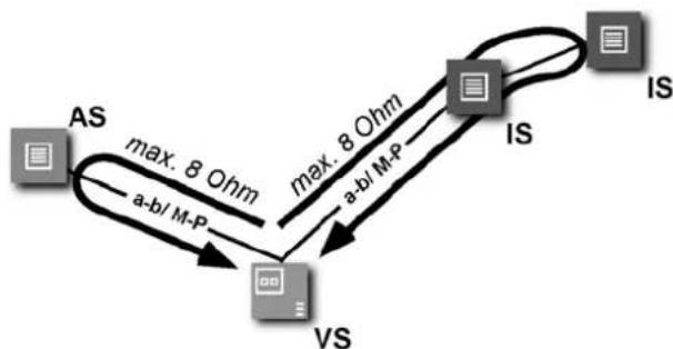
flowchart
graph TD
    AS["AS"] -->|max. 8 Ohm| VS["VS"]
    VS -->|a-b/ M-P| AS
    VS -->|max. 8 Ohm| IS["IS"]
    IS -->|a-b/ M-P| VS
8 Ohm:
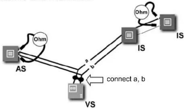
flowchart
graph TD
    AS["AS"] -->|a| VS["VS"]
    VS -->|b| IS["IS"]
    IS -->|b| Ohm["Ohm"]
    Ohm -->|c| IS
    IS -->|c| Ohm
    style AS fill:#f9f,stroke:#333
    style VS fill:#ccf,stroke:#333
    style IS fill:#cff,stroke:#333
    style Ohm fill:#ffc,stroke:#333
65 m wire length AS-VS (IS-VS) at a cross section of 0.6 mm
115 m wire length AS-VS (IS-VS) at a cross section of 0.8 mm
AS. Outdoor station
IS: Indoor station
VS: Power supply and control unit
Cleaning

Avoid the penetration of water into this device!
Do not use any aggressive or abrasive cleaning supplies!
Please clean the device with a dry or slightly moist rag. Intense dirt can be removed with a mild cleaning supply.
Technical data
Supply voltage: +24 V DC ± 8 % (Power supply & control unit)
24 V (a-b) / 26 V (P-b) in idle state
Dimensions, 1 to 4-gang (W x H x D):
Front plate 178.5 x 226 x 4 mm (Material incl. gasket)
DCM UP flush box 134 x 183 x 40 mm
Dimensions, 2 to 8-gang (W x H x D):
Front plate 178.5 x 314 x 4 mm (Material incl. gasket)
DCM flush box 134 x 271 x 40 mm
Labelling field (W x H):
1 to 4-gang 71 x 85 mm
2 to 8-gang 71 x 173 mm
Input current: I(a) = 0,1 mA, I(P) = 26 mA in idle state
Max. input current: I(amax) = 14 mA, I(Pmax) = 150 mA
Protection level: IP44, according to DIN EN 50486
Admissible ambient temperature: -20 °C ... +50 °C
Operation humidity: 0 to 80 % r. h.
Installation height: Recommended 1.50 m
Acceptance of guarantee
We accept the guarantee in accordance with the corresponding legal provisions.
Please return the unit postage paid to our central service department giving a brief description of the fault:
ALBRECHT JUNG GMBH & CO. KG
Service-Centre
Kupferstr. 17-19
44532 Lünen
Germany
Service-Line:0 23 55 . 80 65 51
Fax: 0 23 55.80 61 89
The €-sign is a free trade sign addressed exclusively to the authorities and does not include any warranty of any properties.
Technical subjects to change.
EN_PI_TKASxx
A Art0030823 1v04AP.doc
02/2010
0024099700
- Table of content
- Safety instructions
- Application / Brief description
- Application
- Brief description
- Wiring and installation
- Wiring example 6-wire technique
- Connecting diagram Possible connection for a door release relay
- Installation
- Flush mounted housing
- Connection possibilities:
- Installation frame
- Inscription field
- Closing the device
- Opening the device
- Commissioning
- Setting the button layout
- DIP switch cover
- Buttons
- Button layout: Setting the DIP switches
- Activating the button layout
- Fitting the button
- Bell button programming
- Basic principle
- Programming a bell button
- Programming a second indoor station to a bell button (parallel call)
- Deleting the programming
- Setting and blocking AS-address
- Setting and cancelling a programming block
- Light switching function
- Automatic light switching
- Light switching
- Nameplate illumination
- Setting parameters with DIP switches
- Select parameter
- Set value
- Activate parameter mode
- Set switch 8 to ON.
- Apply parameter
- Deactivate parameter mode
- Set switch 8 to OFF.
- Set the original button layout
- DIP switch table for parameter setting
- Abbreviations:
- Labelling the nameplate
- Fault identification, indication and querying
- General notes on the wiring in DCM video systems
- 6-wire operation
- Principle of loop resistance Measuring loop resistance
- Cleaning
- Technical data
- Acceptance of guarantee
- ALBRECHT JUNG GMBH & CO. KG
- Service-Centre
Brand : JUNG
Model : TKASVAL114WW
Category : Security Camera