
TKISES2914 - Security Camera JUNG - Free user manual and instructions
Find the device manual for free TKISES2914 JUNG in PDF.


| Product Type | Security Camera |
| Brand | JUNG |
| Model | TKISES2914 |
| Image Sensor | 1/2.8" Progressive Scan CMOS |
| Resolution | 1920 x 1080 (Full HD) |
| Lens | 4mm fixed, F2.0 |
| Field of View | 90° (Horizontal), 50° (Vertical) |
| Night Vision | IR LEDs up to 10m |
| Power Supply | 12V DC, 1A (adapter included) |
| Power Consumption | 5W max |
| Connectivity | Wi-Fi 802.11 b/g/n, 2.4GHz |
| Audio | Built-in microphone and speaker (two-way) |
| Storage | microSD card up to 128GB (not included) |
| Motion Detection | Yes, configurable sensitivity and zones |
| Waterproof Rating | IP66 |
| Dimensions | 7.5 x 7.5 x 12 cm (without mount) |
| Weight | 350 g |
| Operating Temperature | -20°C to 50°C |
| Mounting | Wall or ceiling mount included |
| Cleaning | Wipe gently with a dry, soft cloth |
| Safety | Use only supplied power adapter; do not expose to extreme heat |
| Spare Parts | Available from JUNG authorized dealers (power adapter, mount) |
| Repairability | Refer to manual for basic troubleshooting; service by qualified technician |
| General Information | User manual in PDF format available for download |
Frequently Asked Questions - TKISES2914 JUNG
User questions about TKISES2914 JUNG
0 question about this device. Answer the ones you know or ask your own.
Ask a new question about this device
Download the instructions for your Security Camera in PDF format for free! Find your manual TKISES2914 - JUNG and take your electronic device back in hand. On this page are published all the documents necessary for the use of your device. TKISES2914 by JUNG.
USER MANUAL TKISES2914 JUNG
DCM Comfort indoor station
TK IS xx x14 x
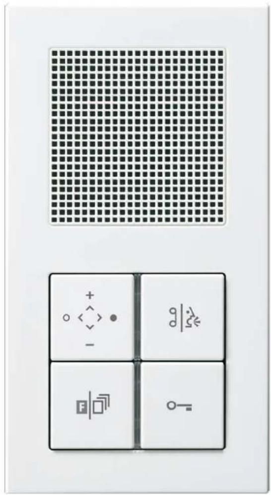
Table of content
Information about this manual....3
Safety instructions.... 3
Application / Brief description.... 4
Application 4
Brief description....4
Device overview 5
Indication and operation....6
Wiring and installation 7
Wiring example....7
Connecting diagram 7
Installation 8
Connection of wires 8
Mounting....8
Commissioning....9
Device settings....9
Storing the device settings....9
Factory settings 9
Function button 10
Internal call 10
Call diversion....11
Automatic door release.... 12
Control function 8 12
Light switching.... 13
Reloading the factory settings 13
Adjusting the function button with the service device 14
Additional functions.... 15
Automatically hands-free operation after internal call 15
Automatic floor door release, control function 11.... 16
Resetting of the additional functions.... 16
Settings 17
Voice volume....18
Volume of voice memo recorder.... 19
Ring tone volume.... 19
Ring tone OFF / ON.... 20
Ring tone selection.... 21
Ring tone 1 (for Outdoor station = 0)....21
Ring tone 2 (for Outdoor station > 0)....22
Ring tone for internal call 23
Ring tone for floor bell button.... 24
Ring tone selection for sub door call.... 25
Operation 27
Start communication, door release, switching light 27
Record, play or delete a ring tone.... 30
Voice memo function: Record, play and delete message 33
Explanation of terms and definitions 35
General notes on the wiring in DCM audio systems 37
Technical data.... 38
Cleaning 38
Acceptance of guarantee 39
Information about this manual
On pages 35 and 36 you can read the "terms and definitions" of this manual. We recommend to read these explanation carefully before you start the adjustment of the indoor station.
Safety instructions

Assembly, installation, and commissioning must only be carried out by a qualified electrician!
For work on systems with 230 V AC mains current the safety requirements of DIN VDE 0100 must be observed.
When installing DCM BUS systems the general safety rules for telecommunication systems in accordance with VDE 0800 must be observed:
- separate cabling for high and low voltage lines
- minimum distance of 10 cm for joint cabling arrangements,
- use of separators between high and low voltage lines in joint cable ducts.
• use of standard telecommunication cables, e. q. J-Y (St) Y with 0.8 mm diameter

Suitable lightning prediction must ensure that a voltage of 32 V DC will not be exceeded at the DCM BUS wires a and b.
DCM = Door Communication Management
Application / Brief description
Application
• acoustical and optical indication of front door and internal calls
- hands-free communication with high audio quality (full duplex)
• door release function
- switching light
- integrated frame for the design ranges AS 500, A creation and CD 500 Combination with other devices possible for the LS design ranges (up to 5-gang frames) and the Flat Design (up to 3-gang)
Brief description
- full duplex operation
- digital voice quality due to active noise rejection
- AEC (Acoustic Echo Cancellation), electronic method for acoustic echo reduction
• automatic calibration of the ambient and network conditions
• high quality sound and great speaker dynamic - optimised acoustic due to bass-reflex speaker system
- hands-free communication
• volume manually adjustable - internal call
- internal call with automatically hands-free communication
- door release button
• automatic door release (main door)
• automatic door release (floor door)
• function button switches lighting (Basic settings)
Alternative assignment: Control function, internal call, automatic door release, call diversion
• voice memory function for storing messages with a length up to 30 seconds
• 15 real sound ring tones (polyphone) - 1 individual ring tone can be recorded with the internal microphone
- ring tone differentiation between main door, floor door and internal call
- sub door call: 4 bell buttons of the outdoor station can be assigned to 4 different ring tones of the indoor station
- ring tone differentiation of 2 outdoor stations
- ring tone volume manually adjustable
- ring tone mute with optical display
• parallel call can be activated - integrated connection for floor door bell
- optical short-term memory of door calls (LED illuminated for max. 30 sec.)
- optical status indication if system is occupied (existing communication)
• audio privacy function - connection: 3-wire-technique
• automatic call cut-off
• electret capacitor microphone - audio- and video indoor stations can be combined in the same installation
Device overview
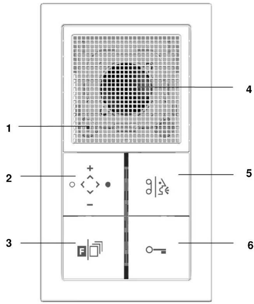
1 Microphone
2 Ring tone button / Volume
3 Function button
4 Loudspeaker
5 Communication button
6 Door release button
LED indication
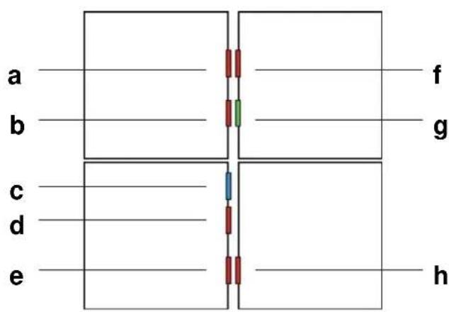
a red Ring tone setting mode
b red Ring tone on/off
c blue Operation LED
d red Setting mode for function button
e red Call diversion / Automatic door release active or internal call transmitted
f red Voice memo LED
g green Talking-, occupied-, door call indication
h red Active door release
Indication and operation
○  | Ring tone button | Adjustment of ring tone volumeRing tone deactivationAdjustment of talking volumeInitiate setting mode for ring tones |
| IndicationLED red (b) | LED on = Ring tone deactivated | |
 | Communication button | Start/end of hands free communicationRecording / recall voice memo |
| IndicationLED green (g)LED red (f) | (g) off: no communication(g) on: talking mode(g) flashing: incoming door call(g) flashing fast: communication occupied(f) flashing: voice memo function, new message | |
 | Function button | Activation of the assigned functionInitiate the setting mode of the function button |
| IndicationLED red (e) | (e) on: Call diversion or automatic door release is activated(e) flashing: Internal call transmitted | |
 | Door release button | Activation of door release (and light, if light switch function is activated) |
| IndicationLED red (h) | LED on: for approx. 3 s when door release is activated | |
| ### | LED blue | Operation LED |
| IndicationLED blue (c) | Ready for operation |
Wiring and installation
Wiring example
Please observe cable length and loop resistance.
Indoor station
Indoor station
Outdoor station
Power supply & control unit
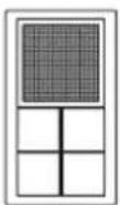
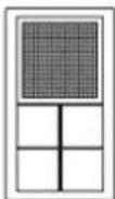
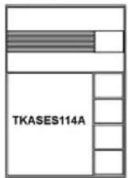
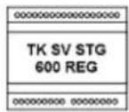
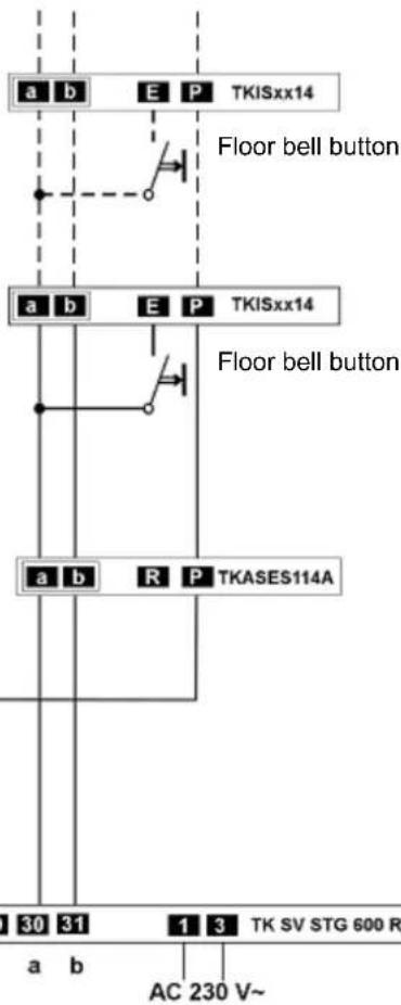
Door release relay and illumination
Connecting diagram
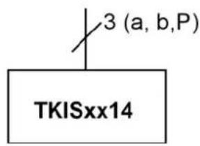
Installation
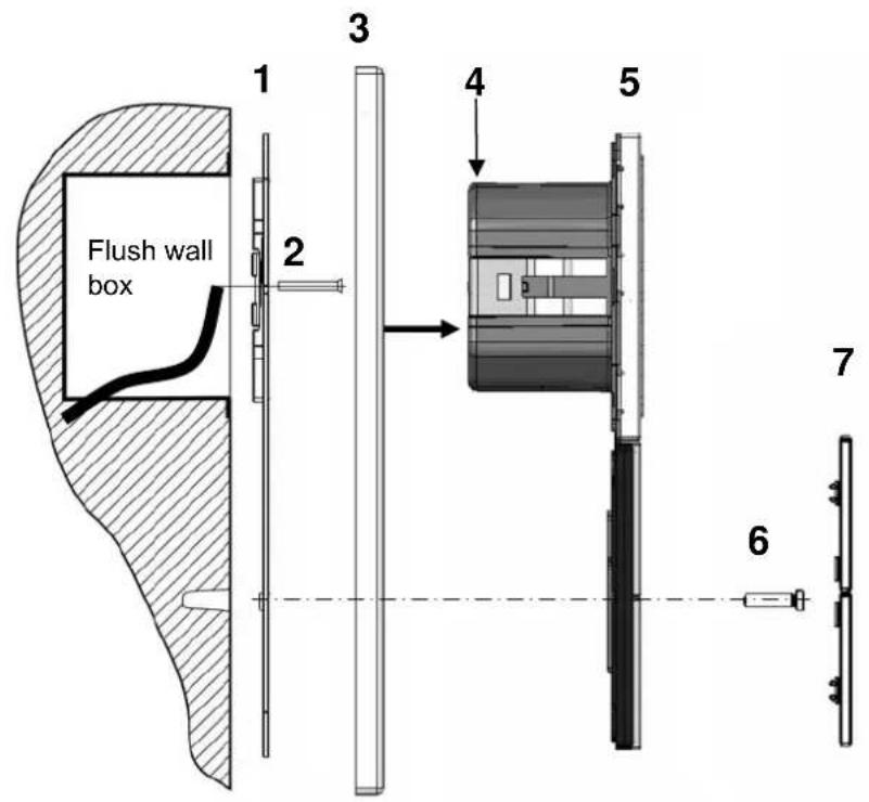
- Installation into flush wall boxes according to DIN 49 073. Do not paint or wallpaper over the supporting frame (1).
- Connection as wiring example (page 7).
Installation
Reverse side of device
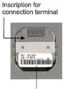
Label with serial number of the device
1 Supporting frame, 2 Wall box screws, 3 Design frame,
4 Connection terminal with connection block, 5 Main unit, 6 Plastic screws, 7 Cover kit
Connection of wires
Type of wire: Telecommunication cable J-Y (St) Y with twisted pairs. The usual diameter is 0.6 mm or 0.8 mm (see chart on page 37)
- Remove the connection block (4).
- Connect the wires to the connection block as inscribed (A B E P) on the reverse side of the device.
Mounting
- For the connection of the device with the plastic screws (6) drilled holes of 6 x10 mm are required. Please use the supporting frame to mark the holes.
- Connect the supporting frame (1) with the delivered screws (2) onto the wall box.
- Put the design frame (3) onto the main unit (5) and plug the wired connection block onto the connection terminal (4).
- Latch the main unit (5) with the design frame (3) onto the supporting frame (1).
- Connect the main unit (5) to the supporting frame (1) with the delivered plastic screws. Tighten the plastic screws only finger tight.
- Clip on the cover kit (7) as shown in the device overview on page 5.
Commissioning
• Install all devices of the DCM system
- Short-circuit test for a-, b- and P-wires
- Switch on supply voltage
Following functions should work without programming the indoor station:
- Communication of indoor station with outdoor station
- Door release function
- Switching light
- Programming of entire DCM system is described in the manual of the outdoor station
Device settings
Storing the device settings
The indoor station is equipped with an EEPROM. After mains voltage failure following remains saved in the EEPROM: Selected ring tone, ring tone volume/mute, activated call diversion, internal call, automatic door release, control functions and light switching and voice memo.
Factory settings
| Limited communication time approx. 1 min | |
| Timeout setting mode approx. 8 s | |
| Indication of green LED after pushing com-munication button when communication is occupied | 3 x |
| Stand-by after internal call approx. 30 s |
Signs and symbols
| acknowledge tone | |
| ring tone | |
| slow LED flashing: 0.5 s ON / 0.5 s OFF | |
| fast LED flashing: 0.125 s ON / 0.125 s OFF | |
| LED illuminated | |
| LED pulse flashing: 0.5 s ON / 1.5 s OFF | |
| LED OFF | |
| short centrically push of button | |
| short push of button section | |
| push button until .... | |
| release the button | |
| sound of loudspeaker / indoor station | |
| voice, talking massage |
Function button
One function can be assigned to the function button.
An additional function can be adjusted:
- "automatic main door release" with additional function "automatic floor door release" or
• automatic hands-free operation after internal call
Internal call
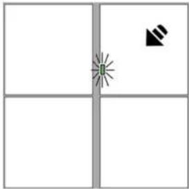 | PreparationDCM system is in idle mode.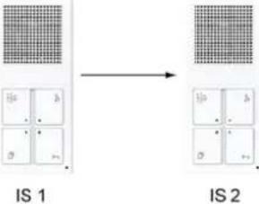 Target indoor station (IS2):Push communication button. Target indoor station (IS2):Push communication button. | |
 | [T205] | Starting setting mode at indoor station (IS1)Push function button (for approx. 8 s)until you can hear acknowledge tone.fast LED flashingrelease the function button |
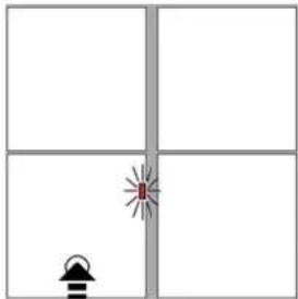 |  | fast LED flashingPush function button at BOTTOM sectionacknowledge toneLED is illuminated for approx. 3 sLED is OFF |
 | Target indoor station (IS2):If green LED is illuminated push communication button.Green LED is OFF.After 60s the target indoor station (IS2) automatically switches into idle mode. | |
| Now you can activate aninternal callto call indoor station (IS2) by means of pushing the function button (IS1). | ||
Call diversion
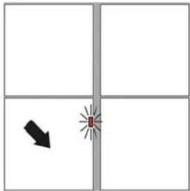
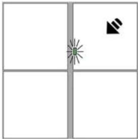
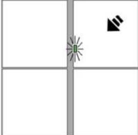 | PreparationDCM system is in idle mode.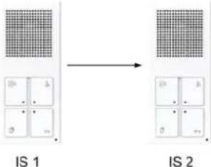 Target indoor station (IS2):Push communication button. Target indoor station (IS2):Push communication button. | |
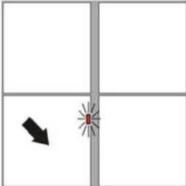 | [G0ZA] | Starting setting mode at indoor station (IS1)Push function button (for approx. 8 s)until you can hear acknowledge tone.fast LED flashingrelease the function button |
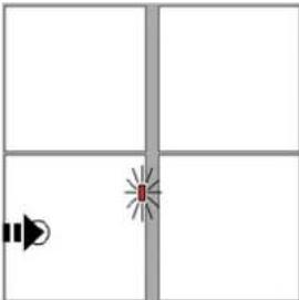 |  | fast LED flashingPush function button at LEFT sectionacknowledge toneLED is illuminated for approx. 3 sLED is OFF |
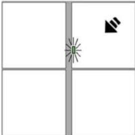 | Target indoor station (IS2):If green LED is illuminated push communication button.Green LED is OFF.After 60s the target indoor station (IS2) automatically switches into idle mode. |
Now you can activate/deactivate a call diversion to a selected indoor station (IS2) by means of pushing the function button (IS1).
Automatic door release
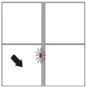 |  | PreparationDCM system is in idle mode.Push function button (for approx. 8 s)until you can hear acknowledge tone.fast LED flashingrelease the function button |
 | ||
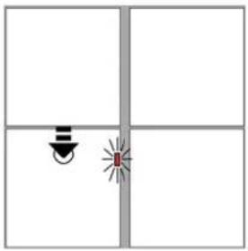 |  | fast LED flashingPush function button at TOP sectionacknowledge toneLED is illuminated for approx. 3 sLED is OFF |
| [6WA2] | ||
 |
Now you can activate/deactivate the automatic door release by means of pushing the function button.
Control function 8
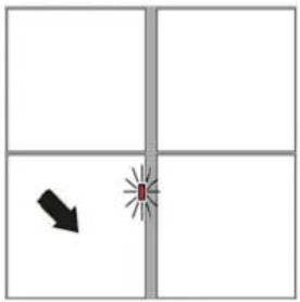 |  | PreparationDCM system is in idle mode.Push function button (for approx. 8 s)until you can hear acknowledge tone.fast LED flashingrelease the function button |
 | ||
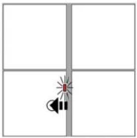 |  | fast LED flashingPush function button at RIGHT sectionacknowledge toneLED is illuminated for approx. 3 sLED is OFF |
 |
Now you can activate the control function 8 by means of pushing the function button.
Light switching
Resetting the function button to the function „light switching“ takes place by means of reloading the factory settings.
Reloading the factory settings
| Beep | Attention !All settings are reset to factory settings.Push ring tone button and function button (for approx. 8 s) until you can hear acknowledge tone.LED is illuminated for approx. 3 sthen the LED is OFFThe indoor station switches into idle mode.release the buttons | |
Now you can switch the light by means of pushing the function button.
Adjusting the function button with the service device
The initiation starts always with the key combination *95#Ser.-Nr.#.
flowchart
graph TD
    A["Outdoor station"] --> B["Floor door bell button"]
    B --> C["IS 228515"]
    C --> D["IS 228520"]
IS (228515) is assigned to a bell button of the outdoor station.
IS (228520) will be parallel assigned to the IS (228515).
With the following key combination IS (228520) operates parallel with IS (228515).
* 99 # 228520 # 228515 #
Note:
Deleting the parallel function with ParSNr = 0.
* 99 # 228520 # 0 #
Ser.-Nr. = Serial number of the indoor station which should be adjusted.
ZielSNr. = Serial number of the target indoor station for a call diversion
IntSNr. = Serial number of the target indoor station for an internal call
ParSNr. = Serial number of the (first) indoor station to which the additional indoor station should be assigned.
Additional functions
One of the following functions can be additionally adjusted:
- Automatically hands-free operation after internal call
• Automatic floor door release, control function 11
Automatically hands-free operation after internal call
When an indoor station receives an internal call, an automatically hands-free operation will be activated. It is not required to accept the call by means of pushing a button. The person at the calling indoor station can directly start talking.
(This function will be adjusted at the "receiving" indoor station.)
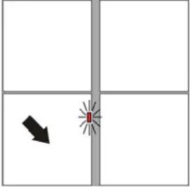 |  | PreparationDCM system is in idle mode.Push function button for longer than 12 s.After approx. 8 s you can hear an acknowledge tone and the LED is flashing fast.After further 4 s you can hear a second acknowledge tone and the LED of the ring tone button starts pulse flashing.release the function button |
 | ||
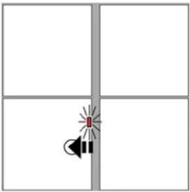 |  | Push function button at RIGHT sectionacknowledge toneLED is illuminated for approx. 3 sLED is OFF |
Automatic floor door release, control function 11
When the function button is adjusted with the function automatic door release (e.g. for the main entrance door in a clinic centre) then the additional control function 11 involves another door release relay (e.g. for the floor entrance door of the clinic centre). This relay will be activated by means of pushing the floor bell button.
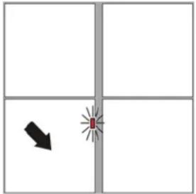 |  | PreparationDCM system is in idle mode.Push function button for longer than 12 s.After approx. 8 s you can hear an acknowledge tone and the LED is flashing fast.After further 4 s you can hear a second acknowledge tone and the LED of the ring tone button starts pulse flashing.release the function button |
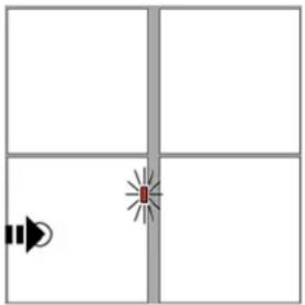 |  | Push function button at RIGHT sectionacknowledge toneLED is illuminated for approx. 3 sLED is OFF |
Now you can activate/deactivate the automatic door release for the floor door and the main entrance door together.
Resetting of the additional functions
The resetting of the additional functions takes place by means of loading the factory settings. Attention! All settings will be reset.
Settings
Signs and symbols
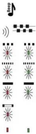 | acknowledge tone | |
| ring tone | ||
| slow LED flashing: 0.5 s ON / 0.5 s OFF | ||
| fast LED flashing: 0.125 s ON / 0.125 s OFF | ||
| LED illuminated | ||
| LED pulse flashing: 0.5 s ON / 1.5 s OFF | ||
| LED OFF | ||
| [2A7Y] | short centrically pushing of button | |
| short pushing of button section | ||
| push button until .... | ||
| release the button | ||
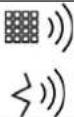 | sound of loudspeaker / indoor station | |
| voice, talking message | ||
Voice volume
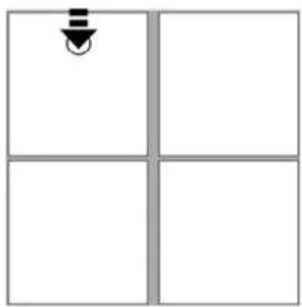 | PreparationThe indoor station must be in talking mode.8 voice volume levels can be adjusted:Increase voice volumePush ring tone button at the TOP section (for approx. 1 s).the voice volume increases | |
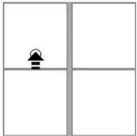 | Decrease voice volumePush ring tone button at the BOTTOM section (for approx. 1 s).the voice volume decreases | |
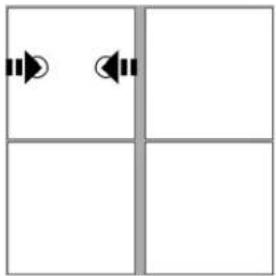 | Repeat the action as long as the desired volume is reached.Average voice volume (= factory setting)Push ring tone button LEFT or RIGHT. |
Volume of voice memo recorder
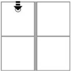 | )))) | PreparationStart the voice memo (see Voice memo function: , page 33)8 voice volume levels can be adjusted:Increase voice volumePush ring tone button at the TOP section (for approx. 1 s).the voice volume increases |
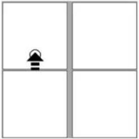 | )))) | Decrease voice volumePush ring tone button at the BOTTOM section (for approx. 1 s).the voice volume decreasesRepeat the action as long as the desired volume is reached. |
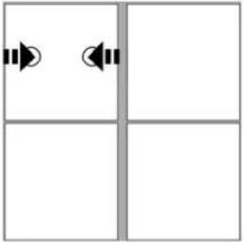 | )))) | Average voice volume (= factory setting)Push ring tone button LEFT or RIGHT. |
Ring tone volume
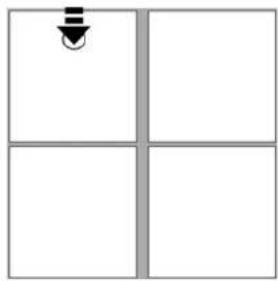 |  | PreparationDCM system is in idle mode.8 voice volume levels can be adjusted for all ring tones:Increase ring tone volumePush ring tone button at the TOP section (approx. 1 s).you can hear the adjusted ring tonenow the volume is one level louder |
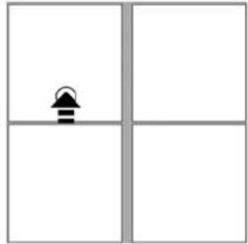 | 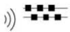 | Decrease ring tone volumePush ring tone button at the BOTTOM section (approx. 1 s).you can hear the adjusted ring tonenow the volume is turned down one levelRepeat the action as long as the desired volume is reached. |
Ring tone OFF / ON
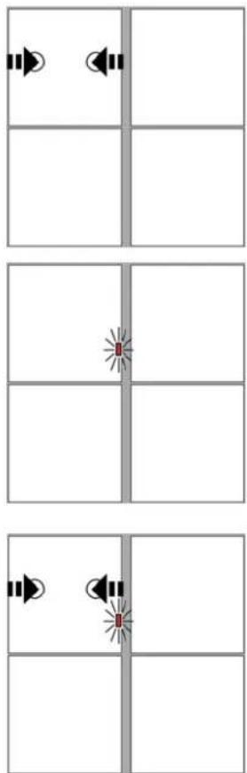

Preparation
DCM system is in idle mode.
Ring tone OFF
- Push ring tone button LEFT or RIGHT.
The LED is illuminated, the ring tone is OFF.
Ring tone ON
- Push ring tone button LEFT or RIGHT.
- the LED turns off, the ring tone is ON again.
Ring tone selection
Various outdoor station can be installed into a DCM system, e.g. in buildings with various entrances. At the indoor station you can assign 2 different ring tones for the entrances. The first ring tone can be assigned to the main outdoor station. The second ring tone can be assigned to all other connected outdoor station.
Ring tone 1 (for Outdoor station = 0)
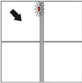 |  | PreparationDCM system is in idle mode.Push ring tone button (for approx. 8 s)until you can hear acknowledge tone.fast LED flashingRelease the ring tone button. |
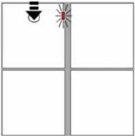 | 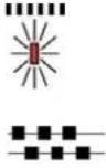 | The TOP LED of the ring tone button flashes fast.Push ring tone button at the TOP section.You can hear the next ring tone.Now this ring tone is selected as the main ring tone 1.Repeat the action until the desired ring tone is selected.After approx. 8 s the indoor station turns into idle mode. The LED turns off. |
Ring tone 2 (for Outdoor station > 0)
 |  | PreparationDCM system is in idle mode.Push ring tone button (for approx. 8 s)until you can hear acknowledge tone.fast LED flashingRelease the ring tone button. |
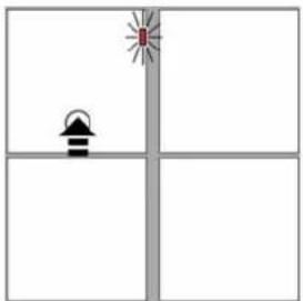 | 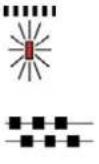 | The TOP LED of the ring tone button flashes fast.Push ring tone button at the BOTTOM section.You can hear the next ring tone.Now this ring tone is selected as the ring tone 2.Repeat the action until the desired ring tone is selected.After approx. 8 s the indoor station turns into idle mode. The LED turns off. |
Ring tone for internal call
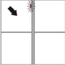 |  | PreparationDCM system is in idle mode.Push ring tone button (for approx. 8 s)until you can hear acknowledge tone.fast LED flashingRelease the ring tone button. |
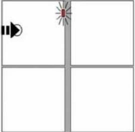 |  | The TOP LED of the ring tone button flashes fast.Push ring tone button at the LEFT section.You can hear the next ring tone.Now this ring tone is selected for the internal call.Repeat the action until the desired ring tone is selected.After approx. 8 s the indoor station turns into idle mode. The LED turns off. |
Ring tone for floor bell button
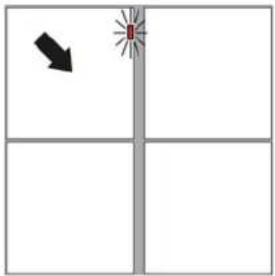 |  | PreparationDCM system is in idle mode.Push ring tone button (for approx. 8 s)until you can hear acknowledge tone.fast LED flashingRelease the ring tone button. |
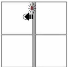 |   | The TOP LED of the ring tone button flashes fast.Push ring tone button at the RIGHT section.You can hear the next ring tone.Now this ring tone is selected for the floor bell buttonRepeat the action until the desired ring tone is selected.After approx. 8 s the indoor station turns into idle mode. The LED turns off. |
Ring tone selection for sub door call
Note:
The assignment of a sub door call at the outdoor station is only possible with the service device (see product information of TK-SERVICE).
| Start setting mode | ||
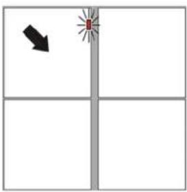 |  | PreparationDCM system is in idle mode.Push ring tone button for longer than 12 s.After approx. 8 s you can hear acknowledge tone.fast LED flashing ...After further 4 s you can hear a second acknowledge tone.LED starts fast pulse flashingRelease the ring tone button.Now the indoor station is ready for the following assignment: |
 | ||
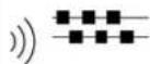
| Selection sub door call 1 (Serial-no.+1) | ||
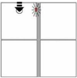 |  | LED pulse flashingPush ring tone button at the TOP section.You can hear the next ring tone.Now this ring tone is selected for the sub door call 1Repeat the action until the desired ring tone is selected. |
 | ||
| Selection sub door call 2 (Serial-no.+2) | ||
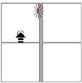 |  | LED pulse flashingPush ring tone button at the BOTTOM section.You can hear the next ring tone.Now this ring tone is selected for the sub door call 2Repeat the action until the desired ring tone is selected. |
| [H×DX] | ||
Selection sub door call 3 (Serial-no.+3)
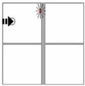 | 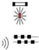 | LED pulse flashing • Push ring tone button at the LEFT section. • You can hear the next ring tone. Now this ring tone is selected for the sub door call 3 |
| Repeat the action until the desired ring tone is selected. |
Selection sub door call 4 (Serial-no.+4)
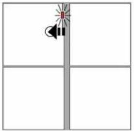 |  | LED pulse flashingPush ring tone button at the RIGHT section.You can hear the next ring tone.Now this ring tone is selected for the sub door call 4Repeat the action until the desired ring tone is selected. |
Finish setting mode
After approx. 8 s the indoor station turns into idle mode. The LED turns off.
Operation
Start communication, door release, switching light
Start communication after incoming call (Door call or internal call)
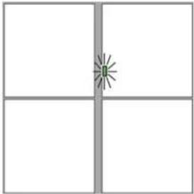 |  | Incoming callYou can hear the selected ring tone and the green LED of the communication button flashes. |
 | ||
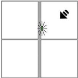 |  | Push the communication button to start the connection (max. 1 s).The green LED is illuminated.Hands-free operation: Full duplex operation, pushing the button is not required.The communication will be stopped:by means of pushing the communication button,when the preset communication time of the outdoor station is elapsed (factory setting: 1min.)by means of pushing the door release button. |
Start communication without incoming call
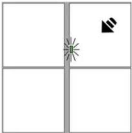 |  | This function can be deactivated with the SERVICE DEVICE (Communication only after incoming call).Push the communication button to start the connection (max. 1 s).The green LED is illuminated.Now communication is possible. |
Stop communication
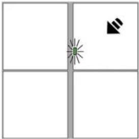 | The communication will be stopped:by means of pushing the communication button (max. 1 s)when the preset communication time of the outdoor station is elapsed (factory setting: 1min.)by means of pushing the door release button.Disconnected communication: The LED turns off. |
Door release
natural_image
Four-panel diagram showing a central vertical line with two red starburst symbols and a black arrow pointing downward (no text or labels)
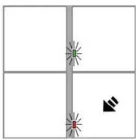
- Push the door release button to open the door.
When light switching function* is activated:
- Push communication button
- Push the door release button to open the door.
Light switching
natural_image
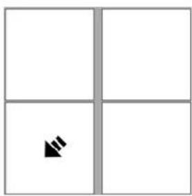
Simple 2x2 grid with a black arrow symbol in the bottom-left cell (no text or labels)- Push the function button, when function button is adjusted with light switching (factory setting).
or
natural_image
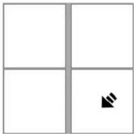
Simple grid with four quadrants and one arrow symbol in the bottom-right quadrant (no text or labels)When light switching function* is activated:
- Push the door release button, if no communication is activated. The LED is not illuminated.
* = please see explanation of terms and definitions on page 35
Features of the function button
Short push of the function button (max. 1 s). Depending on the set function the indoor station indicates the action with visual or acoustic signals:
| Beep | ||
| Light switching - - | ||
| Internal call | √ | flashing |
| Call diversion ON - | √ | |
| Call diversion OFF - - | ||
| Automatic door release ON - | √ | |
| Automatic door release OFF - - |
Automatic floor door release function
When the function button is adjusted with the function automatic door release (e.g. for the main entrance door in a clinic centre) then the additional control function 11 involves another door release relay (e.g. for the floor entrance door of the clinic centre). This relay will be activated by means of pushing the floor bell button.
Now you can activate/deactivate the automatic door release for the floor door and the main entrance door together.
Automatically hands-free operation after internal call
When an indoor station receives an internal call, an automatically hands-free operation will be activated. It is not required to accept the call by means of pushing a button. The person at the calling indoor station can directly start talking.
(This function will be adjusted at the "receiving" indoor station)
Record, play or delete a ring tone
You can record a sound or ring tone with the microphone of the indoor station. The max. recording time is approx. 3 s. After recording the new ring tone / sound has to be selected as a new ring tone (see "ring tone selection").
Recording a ring tone
| Beep | PreparationDCM system is in idle mode.Push ring tone button (for approx. 8 s)until you can hear acknowledge tone.fast LED flashingrelease the tone button button | |
| Beep | Fast flashing of the TOP LED of ring tone button.Note:Push the communication button until your ring tone stops!Push the communication button:You can hear first acknowledge tone, ...now the LED of the communication button starts flashing,...with the second acknowledge tone starts the recording time of your ring tone.The LED is illuminated during the recording time.Play your ring tone / sound in front of the microphone with normal volume.The recording stops automatically after 3 s or by means of releasing the communication button. | |
| Beep | ||
| or |
End of setting mode
The indoor station turns automatically back into idle mode. The LED turns OFF.
| Play recorded ring tone | ||
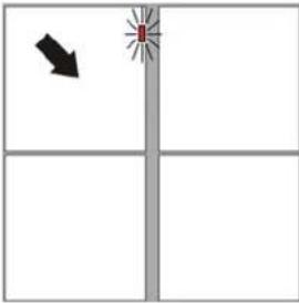 |  | PreparationDCM system is in idle mode.Push ring tone button (for approx. 8 s)until you can hear acknowledge tone.fast LED flashingrelease the ring tone button |
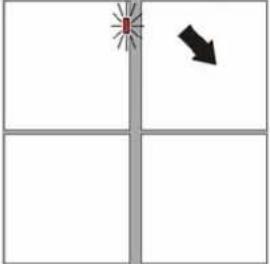 |  [4026] [4026] | Fast flashing of the TOP LED of ring tone button.Push communication button (for approx. 4 s)until you can hear acknowledge tone.release the communication buttonNow you can hear the recorded ring tone. |
Delete the recorded ring tone
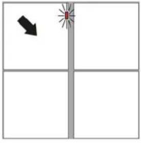 |  | PreparationDCM system is in idle mode. |
 | Push ring tone button until you can hear acknowledge tone (after 8 s).fast LED flashing | |
| release the ring tone button | ||
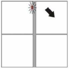 |  | Fast flashing of the TOP LED of ring tone button. |
 | Push communication button:You can hear the first acknowledge tone, ... | |
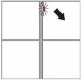 |  | ... now the LED of the communication button starts flashing,... |
| release the communication button | ||
| → | The ring tone is deleted. |
Voice memo function: Record, play and delete message
You can record a voice memo with the microphone of the indoor station. The max. recording time is approx. 30 s. After recording, the new voice memo will be indicated by means of the flashing LED. It is possible to save one voice memo.
You will delete the old voice memo by means of recording a new memo.
Record a voice memo

natural_image
Four-panel grid with a black arrow symbol in the top-right corner (no text or labels)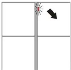
natural_image
Simple diagram with a red starburst and black arrow on a vertical axis, no text or symbols present



Note:
Push the communication button until you have finished talking the voice memo.
- Push the communication button:
You can hear first acknowledge tone, ...
... now the TOP LED of the communication button starts flashing, ...
… with the second acknowledge tone starts the recording time of the voice memo. The LED is illuminated during the recording time.
- Speak the voice memo in front of the microphone with normal volume.
- The recording stops automatically after 30 s or by means of releasing the communication button.
The max. time of the voice memo is 30 s. When the LED starts flashing you have reached the max. recording time. The recording stops automatically.
- Slow LED flashing: The LED indicates a new voice memo. The LED flashes until you play the memo.
Play voice memo
| Slow LED flashing:The LED indicates a new voice memo.The LED flashes until you play the memo. | ||
| Push communication buttonuntil you can hear acknowledge tone(after 4 s). | ||
| release the communication buttonThe voice memo will be played. | ||
| After you played the voice memo, the LED turns off.You can play the voice memo again. |
Delete voice memo
| Push communication button until ...... you can hear acknowledge tone.When the LED starts flashing, release the communication button immediately.The TOP LED of the communication button turns off. The voice memo is deleted. | |||
Explanation of terms and definitions
| AS-address | Every outdoor station is assigned with an outdoor station address.The address enables the differentiation between the various installed outdoor station. Selective communication or door release of e.g. main- or side entrance can be realised. |
| Ready for operation | Incoming door call - You can hear a ring tone and the LED at the communication button flashes. You can activate a communication with the outdoor station by means of a short push of the communication button. |
| Hands-free operation (Full duplex) | Simultaneous communication in both directions. |
| Door call | You release a door call at the assigned indoor station by means of pushing the bell button. A bell button can release a door call at two indoor stations (parallel call). |
| Internal call | An indoor station can call another assigned indoor station for an internal communication. |
| Automatic light switching Programming at the outdoor station. | The light will be switched depending on the ambient brightness when you push the bell button of the outdoor station. The limited brightness value is adjustable. |
| Light switching | The function button of the indoor station is assigned with the function "light switching" (factory setting). A bell button of the outdoor station will switch the light, if the bell button is not assigned to an indoor station. |
| Light switching function Programming at the power supply and control unit. | The door release button can be assigned with an extra function, when the light switching function is activated at the power supply and control unit:You first have to push the communication button before you can release the door with the door release button.Without pushing the communication button you will switch the light with the door release button. |
| Parallel call A second | indoor station can be programmed to a bell button of the outdoor station. |
| Parallel function Programming only with the service device. | Multiple indoor station can respond to one bell button of the outdoor station or the floor bell button. Each further indoor station respond just as the first indoor station. |
| Programming mode The system has to be in programming mode to assign the indoor stations to the desired bell buttons of the outdoor station. | |
| Acknowledge tone Acoustical confirmation | |
| Idle mode The device is ready for a door call or other operation. | |
| Call diversion | An incoming door call will be forwarded from one indoor station to another indoor station. The call diversion has to be activated with the function button. The illuminated LED of the function button indicates the activated call diversion. |
| Talking mode A communication between indoor and outdoor station will be activated by means of pushing the communication button. Die LED of the communication button is illuminated.The LED of the communication button is flashing, when another indoor station is already communicating with the outdoor station.After elapsed talking time, activating the door release or pushing the communication button again, the device turns back into idle mode. | |
| Talking only after incoming door callProgramming only with the service device. | A communication between indoor and outdoor station can only be activated after an incoming door call. |
| Talking time The communication between indoor and outdoor station will be interrupted after a pre-defined talking time (60 s factory setting). The talking time is adjustable. | |
| Control function Command for the control of various relays in the door communication system. | |
| Sub door callProgramming only with the service device. | The sub door call enables to assign 4 additional bell button of the outdoor station to the same indoor station. Each bell button can be assigned to a separate ring tone (e.g.: individual ring tones for each family member). |
| Automatic door release | The door release relay will be activated by means of pushing the bell button. The automatic door release can be activated/deactivated with the function button of the indoor station. The LED of the function button indicates the status.LED ON = automatic door release activatedLED OFF = automatic door release deactivated |
| Door release time The door release relay can be activated for an adjusted time. | |
| Voice memo-function | Record and play a voice memo (message) up to a length of 30 s. |
General notes on the wiring in DCM audio systems
The cabling depends on the building situation and is only limited by its length.
- When selecting the cable length consider: the loop resistance must not exceed max. 20 Ω (table)
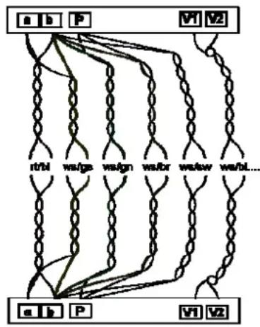
- To keep within the max. permissible loop resistance the wire cross section can be doubled, i.e. two lines are used for one wire (figure). The lines must be twisted.
- When using screened cables: connect the screens to each other and connect on one side to earth (b wire) on the power supply unit
- Choice of line or star wiring
flowchart
graph TD
    A["a"] --> B["b"]
    B --> C["P"]
    C --> D["V1"]
    D --> E["V2"]
    E --> F["..."]
    F --> G["wt/lw"]
    G --> H["we/bl..."]
    H --> I["vt/bl"]
    I --> J["ws/gs"]
    J --> K["ws/ign"]
    K --> L["wa/br"]
    L --> M["we/wn"]
    M --> N["wt/bl..."]
    N --> O["..."]
    O --> P["wt/lw"]
    P --> Q["we/ign"]
    Q --> R["wt/br"]
    R --> S["wt/bl..."]
    S --> T["..."]
    T --> U["wt/lw"]
    U --> V["we/ign"]
    V --> W["wt/br"]
    W --> X["wt/bl..."]
Table: Loop resistance
| Wire length in m | Diameter | |
| 0.6 mm 0.8 mm | ||
| Loop resistance in Ω | ||
| 10 1.22 0.69 | ||
| 20 2.45 1.38 | ||
| 30 3.67 2.07 | ||
| 40 4.90 2.76 | ||
| 50 6.12 3.44 | ||
| 60 7.35 4.13 | ||
| 70 8.57 4.82 | ||
| 80 9.80 5.51 | ||
| 90 11.02 6.20 | ||
| 100 12.24 6.89 | ||
| 150 18.37 10.33 | ||
| 200 24.49 13.78 | ||
| 250 17.22 | ||
| 300 20.66 | ||
Principle of loop resistance Measuring loop resistance
Rule:
No door communication device shall have a longer distance from the power supply & control unit than 20 Ohm!

flowchart
graph TD
    AS["AS"] -->|max. 20 Ohm| VS["VS"]
    VS -->|a,b| AS
    VS -->|max. 20 Ohm| IS["IS"]
    IS -->|a,b| VS
20 Ohm:
160 m wire length AS-VS (IS-VS) at a diameter of 0.6 mm
300 m wire length AS-VS (IS-VS) at a diameter of 0.8 mm
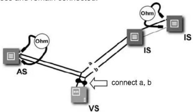
Rule:
Turn OFF 230 V / 50 Hz of the VS.
Connect a and b short circuit at the VS.
All other devices do not disturb the measuring process and remain connected.
flowchart
graph TD
    AS["AS"] -->|a| VS["VS"]
    VS -->|b| IS["IS"]
    IS -->|b| Ohm["Ohm"]
    Ohm -->|c| IS
    IS -->|c| OHm
    style AS fill:#f9f,stroke:#333
    style VS fill:#ccf,stroke:#333
    style IS fill:#cff,stroke:#333
    style Ohm fill:#ffc,stroke:#333
    linkStyle 0 stroke:#000,stroke-width:2px
    linkStyle 1 stroke:#000,stroke-width:2px
    linkStyle 2 stroke:#000,stroke-width:2px
    linkStyle 3 stroke:#000,stroke-width:2px
    linkStyle 4 stroke:#000,stroke-width:2px
    linkStyle 5 stroke:#000,stroke-width:2px
    linkStyle 6 stroke:#000,stroke-width:2px
    linkStyle 7 stroke:#000,stroke-width:2px
    linkStyle 8 stroke:#000,stroke-width:2px
    linkStyle 9 stroke:#000,stroke-width:2px
    linkStyle 10 stroke:#000,stroke-width:2px
AS. Outdoor station
IS: Indoor station
VS: Power supply and control unit
Technical data
Supply voltage:
+24 V DC ± 8 % (Power supply & control unit)
24 V (a-b) / 26 V (P-b) in idle state
Current:
3-wire:
I(a) = 0.1 mA, I(P) = 6.5 mA in idle state
Max. input current: I(Pmax) = 32.5 mA
Protection class: III
Admissible ambient temperature: 0 °C to 40 °C
Operation humidity: 0 to 93 % r. h., no condensation
Installation height: Recommended 1.50 m
Cleaning

Avoid the penetration of water into this device!
Do not use any aggressive or abrasive cleaning supplies!
Please clean the device with a dry or slightly moist rag.
Intense dirt can be removed with a mild cleaning supply.
Acceptance of guarantee
We accept the guarantee in accordance with the corresponding legal provisions. Please return the unit postage paid to our central service department giving a brief description of the fault:
ALBRECHT JUNG GMBH & CO. KG
Service-Centre
Kupferstr. 17-19
44532 Lünen
Germany
Service-Line: 0 23 55 . 80 65 51
Fax: 0 23 55.80 61 89
The €-sign is a free trade sign addressed exclusively to the authorities and does not include any warranty of any properties.
Technical subjects to change.
EN_PI_TKISxx14_1v2.doc
10/2009
0024099500
- DCM Comfort indoor station
- TK IS xx x14 x
- Table of content
- Information about this manual
- Safety instructions
- Application / Brief description
- Application
- Brief description
- Device overview
- LED indication
- Wiring and installation
- Wiring example
- Connecting diagram
- Installation
- Connection of wires
- Mounting
- Commissioning
- Device settings
- Storing the device settings
- Function button
- Light switching
- Adjusting the function button with the service device
- Note:
- Additional functions
- Automatically hands-free operation after internal call
- Automatic floor door release, control function 11
- Resetting of the additional functions
- Settings
- Voice volume
- Volume of voice memo recorder
- Ring tone volume
- Ring tone OFF / ON
- Preparation
- Ring tone OFF
- Ring tone ON
- Ring tone selection
- Ring tone selection for sub door call
- Finish setting mode
- Operation
- Automatic floor door release function
- Record, play or delete a ring tone
- Voice memo function: Record, play and delete message
- General notes on the wiring in DCM audio systems
- Principle of loop resistance Measuring loop resistance
- Technical data
- Cleaning
- Acceptance of guarantee
- ALBRECHT JUNG GMBH & CO. KG
Brand : JUNG
Model : TKISES2914
Category : Security Camera