
TRA241 - Thermostat JUNG - Free user manual and instructions
Find the device manual for free TRA241 JUNG in PDF.


| Product Type | Thermostat |
| Brand | JUNG |
| Model | TRA241 |
| Power Supply | 2x AA batteries (1.5V) |
| Dimensions (HxWxD) | 80 x 80 x 30 mm |
| Weight | 150 g |
| Display Type | LCD with backlight |
| Temperature Range | 5°C to 35°C |
| Accuracy | ±0.5°C |
| Programming | 7-day programmable |
| Modes | Comfort, Economy, Frost Protection |
| Compatibility | Most heating systems (gas, electric, heat pump) |
| Control Type | Push buttons and rotary dial |
| Mounting | Wall-mounted (flush or surface) |
| Wiring | 3-wire (L, N, output) or 2-wire (battery) |
| Maintenance | Clean with a soft, dry cloth; avoid liquids |
| Safety | CE certified, low voltage |
| Spare Parts | Batteries only (user-replaceable) |
| Repairability | Not user-serviceable; contact professional |
Frequently Asked Questions - TRA241 JUNG
User questions about TRA241 JUNG
0 question about this device. Answer the ones you know or ask your own.
Ask a new question about this device
Download the instructions for your Thermostat in PDF format for free! Find your manual TRA241 - JUNG and take your electronic device back in hand. On this page are published all the documents necessary for the use of your device. TRA241 by JUNG.
USER MANUAL TRA241 JUNG
Room temperature controller
GB
Ref.-no.: TR .. 231 ..
TR .. 241 ..
TR .. 236 ..
TR .. 246 ..
Operating instructions
1 Safety instructions

Electrical devices may only be mounted and connected by electrically skilled persons.
Serious injuries, fire or property damage possible. Please read and follow manual fully.
Danger of electric shock. Always disconnect before carrying out work on the devise or load.
A relative air humidity of max. 95% may not be exceeded. Avoid any moisture condensation.
These instructions are an integral part of the product, and must remain with the end customer.
2 Structure of the device
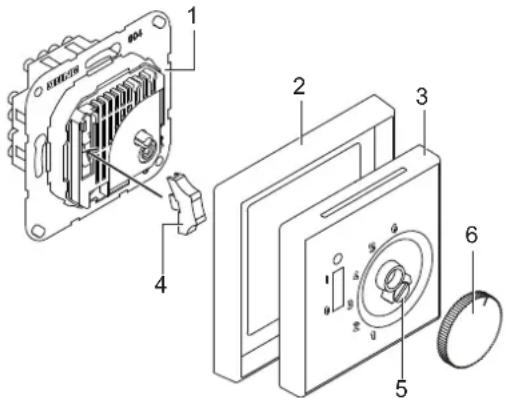
text_image
Exploded view diagram of an electrical switchgear with numbered parts and labeled componentsThe room temperature controller is used to regulate the temperature in closed rooms such as flats, schools, function suites, workshops, etc.
Product characteristics
Neutral conductor required
TR 231 U / TR 241 U:
- Separate terminal for temperature reduction of 5 K (e.g. during night time)
- ON/OFF switch with status LED
- When set temperature is reached the contact opens up.
TR 236 U / TR 246 U:
- No OFF-position
- Without switch and control LED
- When set temperature is reached the NO/NC contact switches over.
4 Information for electrically skilled persons
Installation and electrical connection

DANGER
Electric shock from touching live parts in the installation environment.
An electric shock can be fatal.
Before working on the device, disconnect the power and cover live parts in the area.
- Mount the room temperature controller on an internal wall opposite the heat source if possible.
- Do not mount the room temperature controller on outside walls.
- Avoid draughts from windows and doors.
- Ensure that the normal air circulation in the room reaches the controller without any obstacles.
- External heat sources influence the accuracy of the controller. Avoid direct sunlight and do not place heat-emitting devices in the vicinity of the room temperature controller (heaters, lamps, etc.).
- Dimmers also generate heat.
If a controller is installed in a common switch frame with a dimmer, the distance between them should be as great as possible. When arranging them vertically, the controller must be installed underneath the dimmer.
Connection
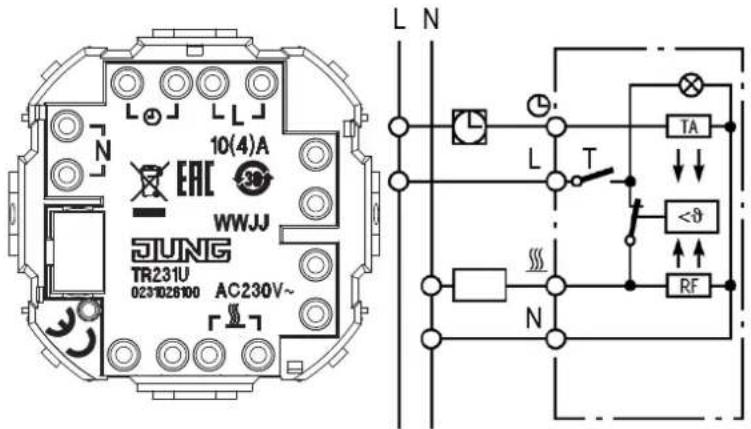
text_image
10(4)A EAC WWJJ JUNG TR231U 0231026100 AC230V~ L N L T TA <θ RF NFig. 2: TR 231 U
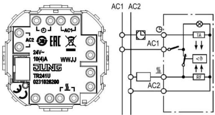
text_image
AC1 AC2 AC1 TA AC2 24V~ 10(4)A WWJJ JUNG TR241U 0231026200Fig. 3: TR 241 U
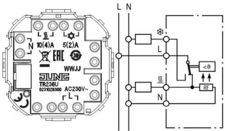
text_image
10(4)A 5(2)A EAC WWJJ JUNG TR236U 0231028300 AC230V~ L N L N <θ RFFig. 4: TR 236 U
text_image
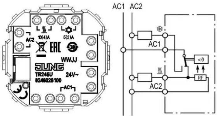
AC1 AC2 AC1 AC2 10(4)A 5(2)A WWJJ EAC 30° JUNG TR246U 24V~ 8246026100 AC1 <θ RFFig. 5: TR 246 U
- Carry out the electrical connection according to the respective wiring diagram.
i Ensure that the neutral conductor N is connected to terminal N. Considerable fluctuations in temperature may otherwise occur.
Conductor cross-section: 1 to 2.5 mm² solid conductor
Symbols used in the wiring diagram
L = L conductor
N = N-conductor
AC1 = 24 V power supply
AC2
① = Connection for clock signal to reduce temperature
= Heating
※ = Cooling
RF = Resistor for thermal feedback
TA = Resistor for night reduction of room temperature
Installation
- Mount room temperature controller in a switch box in accordance with DIN 49073.
Mounting height: approx. 1.5 m above the floor
- Clip the rocker (4) on the switch in the flush insert. (fig. 1)
- Place the center plate together with the frame on the flush insert. The center plate must snap in place in the top left of the housing base.
• Tighten the screw (5). (fig. 1)
- Clip on the setting knob (6). (fig. 1)
5 Operation
Restricting the temperature setting range
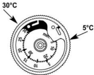
The temperature controller is set ex works to the maximum setting range of 5 °C to 30 °C.
text_image
30°C 5°CFig. 6: Temperature setting range
Two adjustment rings are located in the setting knob. You can use these rings to restrict the temperature setting range required e.g. between 8 °C and 23 °C.
Procedure:
- Select the temperature limits.
Example: min 8 °C, max. 23 °C
- Important!
First position the setting knob roughly in the centre of the required setting range.
Example: The centre point between 8 °C and 23 °C is approximately 15 °C.
- Now remove the setting knob.
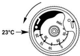
- Set the red locating ring to the max. temperature limit.
Example: 23 °C
- Rotate anti-clockwise.
The numbers on the outer dial apply!
- Insert the tip of a pen in the hole and turn the red ring to the left until it reaches 23^ (max. scale).
text_image
23°C min. 01 02 03 04 05 06 07 08 09 10 11 12 13 14 15 16 17 18 19 20 21 22 23Fig. 7: Temperature setting range max.
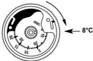
- Set the blue locating ring to the min. temperature limit.
Example: 8 °C
- Rotate clockwise.
The numbers on the inner dial apply.
- Insert the tip of a pen in the hole and turn the blue ring to the right until it reaches 8^ C (min. scale).
text_image
min 8°C 0.2 0.5 1.0 1.5 2.0 3.0 4.0 5.0 6.0 7.0 8.0Fig. 8: Temperature setting range min.
- Clip on the setting knob.
The pointer must be roughly in the centre of the new setting range.
Example: approx. 15 °C
Scale for setting the temperature with dials
1 = approx. 5 °C
2 = approx. 10 °C
3 = approx. 15 °C
4 = approx. 20 °C
5 = approx. 25 °C
6 = approx. 30 °C
Symbols
O Off
I On
6 Technical data
TR 231 U / TR 241 U:
Switching principle 1-pole break contact
+ on/off switch
Temperature range 5 ... 30 °C
Nominal voltage
TR 231 U AC 230 V \~
TR 241 U AC 24 V \~
Nominal current* 10 (4) A
Differential of
functioning temperature approx. 0.5 K
Temperature reduction approx. 4 K
Energy class I = 1 %
The value in brackets indicates the inductive load at a cos φ of 0.6.
TR 236 U / TR 246 U:
Switching principle 1-pole change over contact
without switch
Temperature range 5 ... 30 °C
Nominal voltage
TR 236 U AC 230 V \~
TR 246 U AC 24 V \~
Nominal current*
Heating 10 (4) A
Cooling 5 (2) A
Differential of
functioning temperature approx. 0.5 K
* The value in brackets indicates the inductive load at a cos φ of 0.6.
7 Accessories
Inserts
TR 231 U
TR 241 U
TR 236 U
TR 246 U
Covers
.. TR 231 PL ..
.. TR 241 PL ..
.. TR 236 PL ..
.. TR 246 PL ..
Special knob
MS TR 231 ..
8 Warranty
The warranty follows about the specialty store in between the legal framework as provided for by law.