
02R96VCM - Mixing console YAMAHA - Free user manual and instructions
Find the device manual for free 02R96VCM YAMAHA in PDF.


User questions about 02R96VCM YAMAHA
0 question about this device. Answer the ones you know or ask your own.
Ask a new question about this device
Download the instructions for your Mixing console in PDF format for free! Find your manual 02R96VCM - YAMAHA and take your electronic device back in hand. On this page are published all the documents necessary for the use of your device. 02R96VCM by YAMAHA.
USER MANUAL 02R96VCM YAMAHA
Manufacturer, importer, or dealer shall not be liable for any incidental damages including personal injury or any other damages caused by improper use or operation of Studio Manager for 02R96.
Yamaha makes no representations or warranties with regard to the use of the software and documentation and cannot be held responsible for the results of the use of this manual and the software.
Trademarks
Macintosh is a registered trademark of Apple Computer, Inc. Windows is a registered trademark of Microsoft Corporation. OMS is a registered trademark of Opcode Systems, Inc. All other trademarks are the property of their respective holders and are hereby acknowledged.
Copyright
No part of the Studio Manager for 02R96 software or its documentation may be reproduced or distributed in any form or by any means without the prior written authorization of Yamaha Corporation.
© 2002 Yamaha Corporation. All rights reserved.
Yamaha Web Site
Information about Studio Manager for 02R96, related products, and other Yamaha professional audio equipment is available on the Yamaha Professional Audio Web site at: http://www.yamaha.co.jp/product/proaudio/homeenglish/navi/index.htm.
Specifications and external appearance subject to change without notice.
Contents
1 Getting Started .... 1
Starting Studio Manager....1
Quitting Studio Manager 1
Configuring Studio Manager .... 1
Synchronizing Studio Manager 3
Working with Sessions 3
2 Console Window 4
Input Channels 5
Master Section 7
Output Channels 8
Remote Channels 9
3 Selected Channel Window 10
Input Channels 10
Bus Outs 12
Aux Sends 14
Stereo Out 16
Remote Channels 17
4 Library Window 18
5 Patch Editor Window 20
Input Patch Page 20
Output Patch Page 21
Insert Patch Page 22
Effect Patch Page 23
Direct Out Patch Page 24
6 Surround Editor Window 25
7 Effect Editor Window 26
8 Timecode Counter Window 27
9 Keyboard Shortcuts 28
File Menu 28
Windows Menu 28
Index 29
1 Getting Started
Starting Studio Manager
Windows: Click the Start button and then click Programs->YAMAHA Studio Manager for 02R96->Studio Manager for 02R96.
Macintosh: Open the Studio Manager for 02R96 folder and double-click "SM_02R96."
If a 02R96 is detected while Studio Manager starts up, the Synchronization dialog box appears, from which you can choose to transfer the settings of the 02R96 to Studio Manager or vice versa. See “Synchronizing Studio Manager” on page 3 for more information. If no 02R96 is detected, a new Console window opens.
The ONLINE indicator is displayed while Studio Manager is connected to a 02R96. When no 02R96 is detected, the OFFLINE indicator is displayed.
Quitting Studio Manager
Choose Exit (Quit on the Macintosh) from the File menu.
If there are no unsaved changes, all windows close and Studio Manager quits. If there are unsaved changes, a message asking if you want to save the changes appears. Click Yes to save the changes and quit, click No to quit, or click Cancel to cancel the operation. Studio Manager can also be quit by clicking the Console window's Close button.
Configuring Studio Manager
Selecting Ports
In order to use Studio Manager, you must specify the input and output ports that Studio Manager should use to communicate with the 02R96.
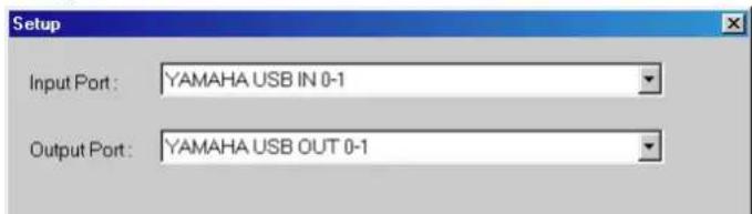
Windows: Choose System Setup from the File menu, and specify the input and output ports on the Setup dialog box, as shown below.
text_image
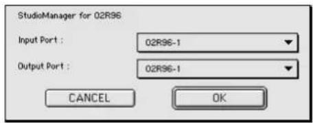
Setup Input Port: YAMAHA USB IN 0-1 Output Port: YAMAHA USB OUT 0-1Macintosh: Choose Select OMS Ports from the File menu, and specify the input and output ports (device names set in OMS Studio Setup) on the Setup dialog box, as shown below.
text_image
StudioManager for 02R96 Input Port : 02R96-1 Output Port : 02R96-1 CANCEL OKNote: Choose OMS MIDI Setup from the File menu, and make sure that the "Run MIDI in Background" option is on.
OMS Studio Setup can be opened directly from Studio Manager by selecting OMS Studio Setup from the File menu.
System Setup
To open the Setup window, choose System Setup from the File menu.
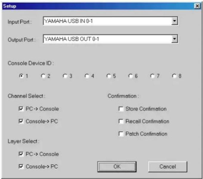
This is the Windows Setup window.
text_image
Setup Input Port: YAMAHA USB IN 0-1 Output Port: YAMAHA USB OUT 0-1 Console Device ID: ● 1 ○ 2 ○ 3 ○ 4 ○ 5 ○ 6 ○ 7 ○ 8 Channel Select: Confirmation: ✓ PC→ Console □ Store Confirmation ✓ Console→ PC □ Recall Confirmation □ Patch Confirmation Layer Select: ✓ PC→ Console ✓ Console→ PC OK CancelThis is the Macintosh Setup window
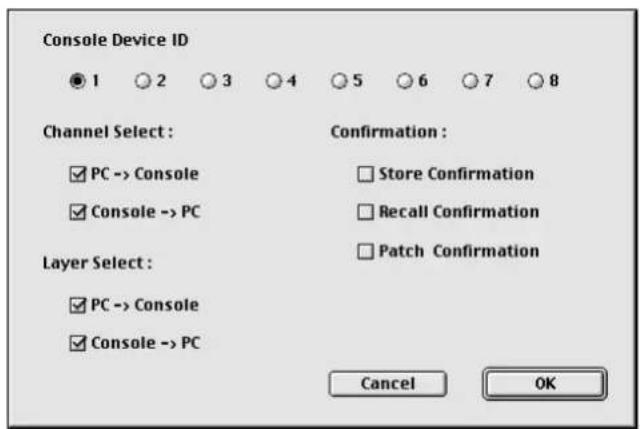
text_image
Console Device ID ● 1 ○ 2 ○ 3 ○ 4 ○ 5 ○ 6 ○ 7 ○ 8 Channel Select: ✓ PC -> Console ✓ Console -> PC Layer Select: ✓ PC -> Console ✓ Console -> PC Confirmation : □ Store Confirmation □ Recall Confirmation □ Patch Confirmation Cancel OKInput Port/Output Port: (Windows only) These pop-up menus are used to select the ports with which Studio Manager communicates with the 02R96.
Console Device ID: Studio Manager can control any one of up to eight 02R96s, each with its own exclusive ID. Select the ID of the 02R96 that you want to control.
Channel Select: These options determine whether or not channel selection is linked. When the PC->Console option is on, selecting a channel on Studio Manager selects the same channel on the 02R96. When the Console->PC option is on, selecting a channel on the 02R96 selects the same channel on Studio Manager.
Confirmation: These options determine whether or not a confirmation dialog box appears when storing, recalling, or patching.
Layer Select: These options determine whether or not Layer selection is linked. When the PC->Console option is on, selecting a Layer on Studio Manager selects the same Layer on the 02R96. When the Console->PC option is on, selecting a Layer on the 02R96 selects the same Layer on Studio Manager.
Synchronizing Studio Manager
If a 02R96 is detected while Studio Manager starts up, or while Studio Manager is up and running, the Synchronization dialog box shown below appears.
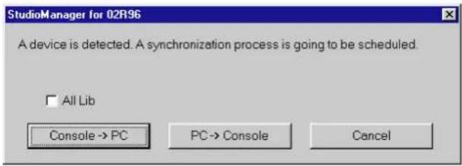
text_image
StudioManager for 02R96 A device is detected. A synchronization process is going to be scheduled. □ All Lib Console → PC PC → Console CancelAll Lib: This option determines whether or not Scene and Library data is synchronized.
Console->PC: Click this button to transfer the settings of the 02R96 to the current Studio Manager Session.
PC->Console: Click this button to transfer the settings of current Studio Manager Session to the 02R96.
Cancel: Click this button to leave the 02R96 and current Studio Manager Session unsynchronized.
Note: Do not operate the 02R96 while synchronization is in progress.
You can resynchronize the system at any time by choosing Re-synchronize from the Synchronization menu.
Working with Sessions
A Studio Manager Session consists of all 02R96 mix settings, including Scene and library data.
• To create a new Session, choose New Session from the File menu.
• To open a previously saved Session, choose Open Session from the File menu.
• To save the current Session, choose Save Session from the File menu.
- To save the current Session with a new name, choose Save Session as from the File menu.
Note: In order to save the current Automix, or the settings of an optional Y56K card, in a Session, you must resynchronize Studio Manager beforehand (Console->PC).
Note: In order to protect the communication port used by Studio Manager, 02R96 communication settings (e.g., MIDI, Remote Layer, Machine Control) are not affected by PC->Console synchronization operations.
Only one Session can be open at a time, so when you create a new Session, or open a previously saved Session, the message "This operation will purge the current session" appears. If there are no unsaved changes, or you do not want to save, click OK. If Studio Manager is offline, the Session is loaded. If Studio Manager is online, the Session is loaded and the synchronization dialog box appears.
2 Console Window
Studio Manager's Console window displays 24 channel strips and a master section. When an Input Channel Layer is selected, 24 Input Channels are displayed. When the Master Layer is selected, Input Channels 49–56, the Bus Out and Aux Send channels are displayed. And when the Remote layer is selected, Remote Channels are displayed.
Many functions can be operated from here by clicking and dragging the various controls and parameters. This is explained in the following sections.
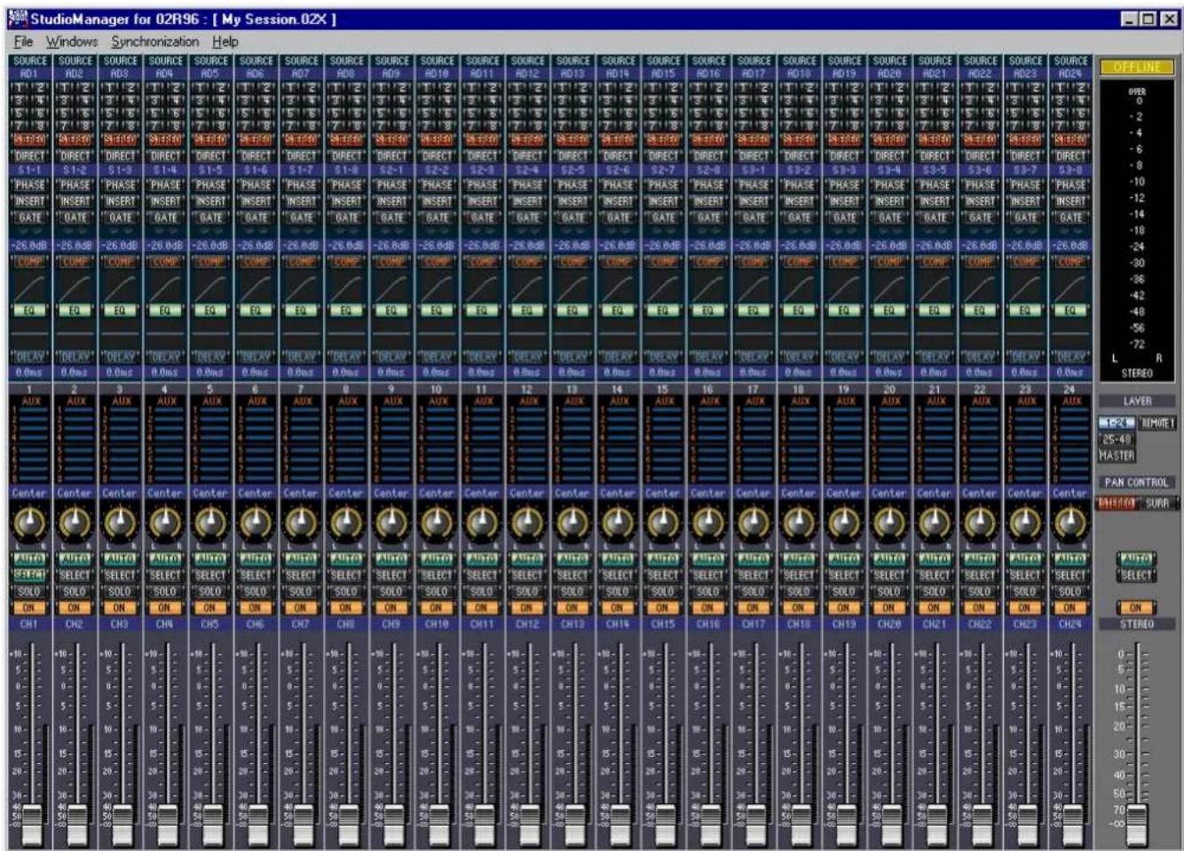
Channels can be viewed in more detail on the Selected Channel window. See page 10 for more information.
Input Channels

text_image
SOURCE RD20 1 2 3 4 5 6 7 8 S1E30 DIRECT S3-4 PHASE INSERT GATE -26.8dB COMP EQ DELAY 0.0ms 20 AUX Center L R AUTO SELECT SOLO ON CH20 19 CENTER LFE 20 22 21 23 24 25 26 27 28① SOURCE parameter
This parameter is used to select an Input source. To select an Input source, click the parameter and choose from the list that appears.
② Routing buttons
These buttons are used to route the Input Channel to the Bus Outs.
③ STEREO button
This button is used to route the Input Channel's signal to the Stereo Out.
④ DIRECT button
This button turns on and off the Input Channel's routing to its Direct Out.
⑤ Direct Out parameter
This parameter is used to select the Direct Out destination. To select a destination, click the parameter and choose from the list that appears.
⑥ PHASE button
This button is used to reverse the signal phase of the channel.
⑦ INSERT button
This button is used to turn on and off the Input Channel's Insert.
⑧ GATE button
This button is used to turn on and off the Input Channel's Gate.
⑨ Gate open/close indicators
These indicators display whether the Gate is open (green) or closed (red).
⑩ Gate threshold
This displays the Gate Threshold, which can be set by dragging.
⑪ COMP button
This button is used to turn on and off the Input Channel's Compressor.
⑫ Compressor curve
This display shows the Compressor's curve.
⑬ EQ button
This button is used to turn on and off the Input Channel's EQ.
⑭ EQ curve
This display shows the Equalizer's curve, which can be set by dragging.
⑮ DELAY button
This button is used to turn on and off the Input Channel's Delay function.
⑯ Delay parameter
This parameter is used to set the delay time of the Delay function. Delay times can be set by dragging.
⑰ Channel number
This is the channel number.
⑱ AUX section
These controls are used to set the levels of the Aux Sends. To set an Aux Send level, drag its bar or click a point along the length of the bar. To turn an Aux Send on or off, click its number.
The following table shows how the Aux Send controls appear depending on the Aux Send On/Off and Pre/Post settings. Aux Sends can be set to pre-fader or post-fader on the Selected Channel window (see “AUX SEND section” on page 11).
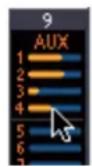
| Aux Send status Appearance | ||
| On or off but no level set Dark blue bar | ||
| Off, pre-fader Green bar outline displays level | ||
| On, pre-fader Green bar displays level | ||
| Off, post-fader Orange bar outline displays level | ||
| On, post-fader Orange bar displays level | ||
⑲ Pan/Aux Send display
This display shows the stereo or surround pan position or, while setting an Aux Send, the Aux Send level in dB.
⑳ PAN control
This control is used to set the Input Channel's stereo or surround pan position. When the PAN CONTROL in the Master Section is set to "STEREO," the Pan control appears as a rotary control, and when set to "SURR," the control appears as dot on a pan graph. The surround pan position can be set by dragging the dot. If you click on the pan graph while holding down the Shift key, the pan immediately jumps to the new position.
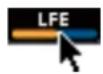
②1 LFE control
When 5.1 Surround mode is selected, this control is used to set the surround LFE Channel level. It appears when the PAN CONTROL in the Master Section is set to “SURR.” To set the LFE level, drag the end of its bar or click a point along the length of the bar.
② AUTO button
This button displays the Automix status of the Input Channel.
②3 SELECT button
This button is used to select the Input Channel.
⑳ SOLO button
This button solos the Input Channel. It appears orange while the channel is soloed.
⑲ ON button
This button turns the Input Channel on and off. It appears orange while the channel is on.
⑳ Short channel name
This is the channel's short name. To edit the name, click it and type.
⑳ Channel fader
This is the Input Channel's fader.
⑳ Channel meter
This meter displays the signal level of the Input Channel.
Master Section

text_image
OFFLINE OVER 0 -2 -4 -6 -8 -10 -12 -14 -18 -24 -30 -36 -42 -48 -56 -72 L R STEREO LAYER 1-24 REMOTE 1 25-48 MASTER PAN CONTROL STEREO SURR AUTO SELECT ON STEREO 0 5 10 15 20 30 40 50 70 -∞ ① ② ③ ④ ⑤ ⑥ ⑦ ⑧① ONLINE status indicator
This indicator shows whether Studio Manager is online or offline.
② Meters
These meters display the output level of the Stereo Out when PAN CONTROL is set to "STEREO," or the Bus Outs used for surround processing when PAN CONTROL is set to "SURR." The Meters in 3-1 and 5.1 Surround modes are shown below.
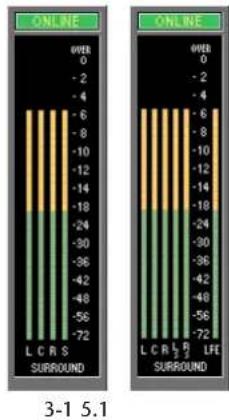
bar
| Category | Value | |---|---| | L C R S SURROUND | -72 | | L C R S SURROUND | -56 | | L C R S SURROUND | -48 | | L C R S SURROUND | -36 | | L C R S SURROUND | -24 | | L C R S SURROUND | -18 | | L C R S SURROUND | -14 | | L C R S SURROUND | -12 | | L C R S SURROUND | -10 | | L C R S SURROUND | -8 | | L C R S SURROUND | -6 | | L C R S SURROUND | 0 | | L C R L P LIFE SURROUND | -72 | | L C R L P LIFE SURROUND | -56 | | L C R L P LIFE SURROUND | -48 | | L C R L P LIFE SURROUND | -36 | | L C R L P LIFE SURROUND | -24 | | L C R L P LIFE SURROUND | -18 | | L C R L P LIFE SURROUND | -14 | | L C R L P LIFE SURROUND | -10 | | L C R L P LIFE SURROUND | -8 | | L C R L P LIFE SURROUND | -6 | | L C R L P LIFE SURROUND | 0 | 3-1 5.1③ LAYER buttons
These buttons are used to select the Layers.
④ PAN CONTROL
These buttons are used to select either "STEREO" (Stereo mode) or "SURR" (Surround mode). The Pan control on the Input Channels is a rotary control when "STEREO" is selected, and a dot on a pan graph when "SURR" is selected.
⑤ AUTO button
This button displays the Automix status of the Stereo Out.
⑥ SELECT button
This button is used to select the Stereo Out. If it's clicked while the Remote Layer is selected, it will light up, but the Stereo Out will not appear in the Selected Channel window.
⑦ ON button
This button turns the Stereo Out on and off. It appears orange while the Stereo Out is on.
⑧ Channel fader
This is the Stereo Out fader.
Output Channels
When the Master Layer is selected, the Bus Out and Aux Send channels are displayed. A Bus Out channel is shown here. Aux Send channels appear the same except that they do not have a STEREO button.

text_image
'STEREO' 'INSERT' 'COMP' EQ 'DELAY' 0.0ms BUS5 AUTO SELECT SOLO ON BUS 5 0 5 10 15 20 30 40 50 70 80 90 16 15 14 13 12 11 10 AUTO ① ② ③ ④ ⑤ ⑥ ⑦ ⑧ ⑨① STEREO button (Bus Out only)
This button is used to route the Bus Out to the Stereo Out.
② INSERT button
This button is used to turn on and off the Bus Out's Insert.
③ COMP button
This button is used to turn on and off the Bus Out's Compressor.
④ Compressor curve
This display shows the Compressor's curve.
⑤ EQ button
This button is used to turn on and off the Bus Out's EQ.
⑥ EQ curve
This display shows the Equalizer's curve, which can be set by dragging.
⑦ DELAY button
This button is used to turn on and off the Bus Out's Delay function.
⑧ Delay parameter
This parameter is used to set the delay time of the Delay function. Delay times can be set by dragging.
⑨ Channel number
This is the channel number.
⑩ AUTO button
This button displays the Automix status of the Bus Out.
⑪ SELECT button
This button is used to select the Bus Out.
⑫ SOLO button
This button solos the Bus Out. It appears orange while the Bus Out is soloed.
⑬ ON button
This button turns the Bus Out on and off. It appears orange while the Bus Out is on.
⑭ Short channel name
This is the channel's short name. To edit the name, click it and type.
⑮ Channel fader
This is the Bus Out's fader.
⑯ Channel meter
This meter displays the signal level of the Bus Out.
Remote Channels
When the Remote Layer is selected, Remote Channels are displayed.

text_image
RMT1-16 ① SELECT ON GM-CH1. ② ③ ④ ⑤ 127① Channel number
This is the channel number.
② SELECT button
This button is used to select the Remote Channel.
③ ON button
This button turns the Remote Channel on and off. It appears orange while the channel is on.
④ Short channel name
This is the Remote Channel's short name. To edit the name, click it and type.
⑤ Channel fader
This is the Remote Channel's fader.
Note: When the remote target setting on the 02R96 is set to anything other than User Defined, the ON buttons and channel faders have no effect, and the name of the specified target is displayed in the channel's short name.
3 Selected Channel Window
The Selected Channel window allows detailed editing of the currently selected channel. To open the Selected Channel window, choose Selected Channel from the Windows menu. The layout of the Selected Channel window depends on the currently selected channel. There are five variations, as follows:
- Input Channel (see below)
- Bus Out (see page 12)
• Aux Send (see page 14) - Stereo Out (see page 16)
• Remote Channel (see page 17)
Input Channels
This is the Selected Channel window for Input Channels.
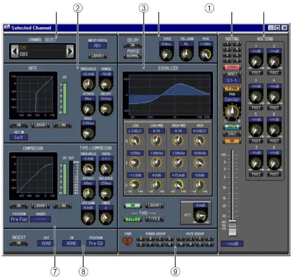
text_image
Selected Channel CHANNEL SELECT CH1 CH1 INPUT PATCH RD1 LIBRARY DELAY ON PHASE NORMAL TIME 8.0ms FE, GAIN 0% MIX +100% ROUTING 1 2 -0.0dB -0.0dB SISTRO DIRECT S1-1 F PAN PAN Center 5 6 AUTO SOLO ON 7 8 -0.0dB -0.0dB -0.0dB -0.0dB -0.0dB -0.0dB -0.0dB -0.0dB -0.0dB -0.0dB -0.0dB -0.0dB -0.0dB -0.0dB -0.0dB -0.0dB -0.0dB -0. 9 ① ② ③ ⑦ ⑧ ⑨ INPUT PATCH RDI LIBRARY GATE CR -10 - 60 -40 -20 0 +18 ON LIBRARY LINK KEY IN Self TIMESHOLD RANGE -26.8dB -56dB RTHACK DECRY 6ms 331ms HOLD 2.56ms EQUILIZER LOW MID HIGH-MID HIGH L.S HELF 0.78 0.78 H.S HELF 125Hz 1.88kHz 1.58kHz 18.8kHz F -11.0dB 0.0dB +15.8dB 0.0dB C -15 -15 -15 -15 -15 -15 -15 -15 -15 -15 -15 -15 -15 -15 -15 -15 -15 -15 -15 -15 -15 -15 -15 -15 -15 -15 -15 -15 -15 -15 -15 -15 -15 -15 - COMPRESSOR TYPE: COMPRESSOR TRESHOLD RATIO -8.8dB 2.5:1 GR OUT 2018 -40 -20 60ms RELENSSE 258ms ON LIBRARY LINK POSITION ORDER Pre Fad ---- IN POSITION PRE EQ ON LIBRARY TYPE TYPE RTT -12 PWR FADER GROUP MUTE GROUP +/-codB① CHANNEL SELECT, INPUT PATCH & LIBRARY section
Channels can be selected by clicking the Channel ID and selecting from the list that appears, or by clicking the left and right Channel Select buttons. The long channel name is displayed below the Channel ID. To edit the name, click it and type. The INPUT PATCH parameter is used to select an input source. To select an input, click the parameter and choose from the list that appears. The LIBRARY button opens the Channel Library window.
② GATE section
This section contains the Gate controls and display graph for the currently selected Input Channel. The rotary controls are used to set the threshold, range, attack, decay, and hold. The GR meter indicates the amount of gain reduction being applied by the Gate. The ON button turns the Gate on and off. The LINK button links the Gate of the currently selected Input Channel with the Gate of its partner channel. The KEY IN parameter is used to select a Gate trigger source. The LIBRARY button opens the Gate Library window.
③ EQUALIZER section
This section contains the EQ controls and display graph for the currently selected Input Channel. The rotary controls are used to set the gain, center frequency, and Q of each band, and the pre-EQ attenuation level. EQ can also be set by dragging the EQ curve on the EQUALIZER graph. The ON button turns the EQ on and off. The TYPE buttons select the EQ type. The LIBRARY button opens the EQ Library window.
④ DELAY & PHASE section
This section contains the delay and phase controls for the currently selected Input Channel. The rotary controls are used to set the delay time, feedback gain, and feedback mix. The ON button turns the Delay on and off. The PHASE button reverses the channel's signal phase.
⑤ Routing, pan & level section
This section contains the routing, pan, and level controls and the AUTO, SOLO, and ON buttons for the currently selected Input Channel. ROUTING buttons 1–8 are used to route the channel to the Bus Outs. The STEREO button routes the channel to the Stereo Out. The DIRECT button routes the channel to its Direct Out, and the parameter below it selects a Direct Out destination. The F.PAN button turns on and off the Bus Out Follow Pan function. The PAN control is used to pan the channel. The AUTO button displays the Automix status. The SOLO button is used to solo the channel, the ON button, to turn on and off the channel, and the channel fader, to set the channel level.
⑥ AUX SEND section
This section contains the Aux Send controls for the currently selected Input Channel. Use the rotary controls to set the Aux Send levels, and click them to turn Aux Sends on and off. Use the button below each Aux Send control to select pre-fader or post-fader. In Fixed mode, this button is used to turn Aux Sends on and off (the level is fixed at nominal).
When Aux Sends are paired, a heart icon is displayed between them, and the odd-numbered Aux Send control sets the level, while the even-numbered control works as a pan control.
⑦ COMPRESSOR section
This section contains the Compressor controls and display graph for the currently selected Input Channel. The rotary controls are used to set the threshold, ratio, attack, release, gain, and knee. The GR meter indicates the amount of gain reduction being applied by the Compressor. The OUT meter indicates its output level. The ON button turns the Compressor on and off. The LINK button links the Compressor of the currently selected Input Channel with the Compressor of its partner channel. The POSITION parameter is used to specify the position of the Compressor in the signal path. The ORDER parameter is used to specify the order of the Compressor and Insert when both are inserted at the same position. The LIBRARY button opens the Compressor Library window.
⑧ INSERT section
This section contains the Insert parameters for the currently selected Input Channel. The INSERT button turns the Insert on and off. The OUT and IN parameters are used to specify the insert out destination and insert in source respectively. The POSITION parameter is used to specify the position of the Insert in the signal path.
⑨ Pair, FADER GROUP & MUTE GROUP section
This section contains the Pair, Fader and Mute group functions for the currently selected Input Channel. Click the heart icon to pair and unpair the channel with its partner channel. Use the FADER GROUP buttons to add the channel to Fader groups, and use the MUTE GROUP buttons to add it to Mute groups.

Bus Outs
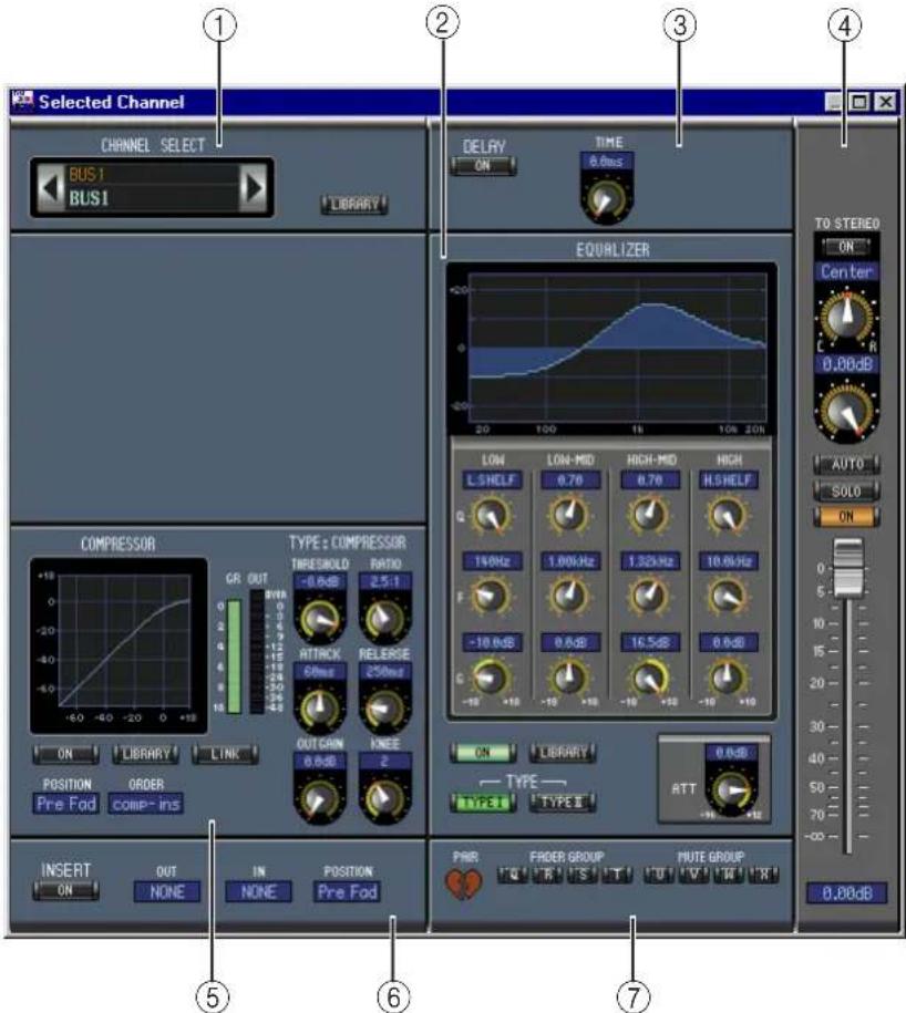
This is the Selected Channel window for Bus Outs.
text_image
Selected Channel CHANNEL SELECT BUS1 BUS1 LIBRARY DELAY ON TIME 8.0ms EQUALIZER TYPE: COMPRESSOR THRESHOLD -0.6dB RATIO 2.5:1 ATTACK RELEASE 68ms 250ms OUT GAIN KNEE 0.6dB 2 ON LIBRARY LINK POSITION ORDER Pre Fad comp-ins INSERT OUT IN POSITION PWR FROER GROUP MUTE GROUP NONE NONE Pre Fod TO STEREO ON Center C R 0.00dB AUTO SOLO ON 19kHz 1.00kHz 1.32Hz 10.0kHz -10.6dB 0.6dB 16.5dB 0.6dB ON LIBRARY TYPE TYPE TYPE II RTT -16 +12 PWR FROER GROUP MUTE GROUP 0.00dB① CHANNEL SELECT section
Channels can be selected by clicking the Channel ID and selecting from the list that appears, or by clicking the left and right Channel Select buttons. The long channel name is displayed below the Channel ID. The LIBRARY button opens the Channel Library window.
② EQUALIZER section
This section contains the EQ controls and display graph for the currently selected Bus Out. It's layout is identical to the EQUALIZER section for Input Channels. See "EQUALIZER section" on page 11 for more information.
③ DELAY section
This section contains the delay controls for the currently selected Bus Out. The rotary control is used to set the delay time, and the ON button turns the Delay function on and off.
④ TO STEREO & level section
This section contains the TO STEREO and level controls and the AUTO, SOLO, and ON buttons for the currently selected Bus Out. The TO STEREO button routes the Bus Out to the Stereo Out, and the rotary controls are used to set the Bus to Stereo level and pan. The AUTO button displays the Automix status. The SOLO button is used to solo the Bus Out, the ON button, to turn the Bus Out on and off, and the channel fader, to set the Bus Out level.
⑤ COMPRESSOR section
This section contains the Compressor controls and display graph for the currently selected Bus Out. Its layout is identical to the COMPRESSOR section for Input Channels. See “COMPRESSOR section” on page 11 for more information.
⑥ INSERT section
This section contains the Insert parameters for the currently selected Bus Out. The INSERT button turns the Insert on and off. The OUT and IN parameters are used to select the insert out destination and insert in source respectively. The POSITION parameter is used to specify the position of the Insert in the signal path.
⑦ Pair, FADER GROUP & MUTE GROUP section
This section contains the Pair, Fader and Mute group functions for the currently selected Bus Out. Click the heart icon to pair and unpair the channel with its partner channel. Use the FADER GROUP buttons to add the channel to Fader groups, and use the MUTE GROUP buttons to add it to Mute groups.
Aux Sends
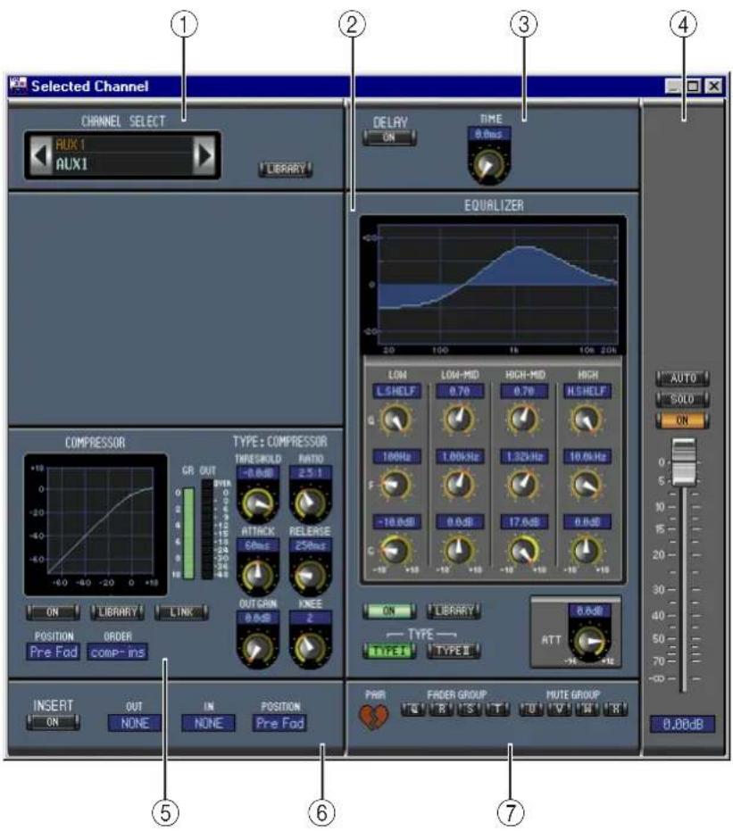
This is the Selected Channel window for Aux Sends.
text_image
Selected Channel CHANNEL SELECT AUX1 LIBRARY DELAY ON TIME 0.0ms EQUALIZER COMPRESSOR TYPE: COMPRESSOR THRESHOLD -0.0 dB RATIO 2.5:1 AVRA ATTACK RELEASE CPuls 25Hz OUTGRIN KNEE 0.0 dB 2 POSITION Pre Fad ORDER comp-ins INIT OUT NONE IN NONE POSITION Pre Fad PART FEDER GROUP MUTE GROUP AUTO SOLO ON ATT -10 Hz 100Hz 100Hz 100Hz 100Hz 100Hz 100Hz 100Hz 100Hz 100Hz 100Hz 100Hz 100Hz 100Hz 100Hz 100Hz 100Hz 100Hz 100Hz 100Hz 100Hz 100MHz 100MHz 100MHz 100MHz 100MHz 100MHz 100MHz 100MHz 100MHz 100MHz 100MHz 100MHz 100MHz 100MHz 100MHz 100MHz 100MHz 100MHz 100MHz 100MHz 100kHz 1.0kHz 1.32kHz 17.6dB 8.6dB TYPE: TYPE II: ATT -14 Hz -18 Hz 8.6dB 8.6dB① CHANNEL SELECT section
Channels can be selected by clicking the Channel ID and choosing from the list that appears, or by clicking the left and right Channel Select buttons. The long channel name is displayed below the Channel ID. The LIBRARY button opens the Channel Library window.
② EQUALIZER section
This section contains the EQ controls and display graph for the currently selected Aux Send. It's layout is identical to the EQUALIZER section for Input Channels. See "EQUALIZER section" on page 11 for more information.
③ DELAY section
This section contains the delay controls for the currently selected Aux Send. The rotary control is used to set the delay time, and the ON button turns the Delay function on and off.
④ Aux Send level section
This section contains the AUTO, SOLO, and ON buttons and the channel fader for the currently selected Aux Send.
⑤ COMPRESSOR section
This section contains the Compressor controls and display graph for the currently selected Aux Send. Its layout is identical to the COMPRESSOR section for Input Channels. See “COMPRESSOR section” on page 11 for more information.
⑥ INSERT section
This section contains the Insert parameters for the currently selected Aux Send. The INSERT button turns the Insert on and off. The OUT and IN parameters are used to specify the insert out destination and insert in source respectively. The POSITION parameter is used to specify the position of the Insert in the signal path.
⑦ Pair, FADER GROUP & MUTE GROUP section
This section contains the Pair, Fader and Mute group functions for the currently selected Aux Send. Click the heart icon to pair and unpair the channel with its partner channel. Use the FADER GROUP buttons to add the channel to Fader groups, and use the MUTE GROUP buttons to add it to Mute groups.
Stereo Out
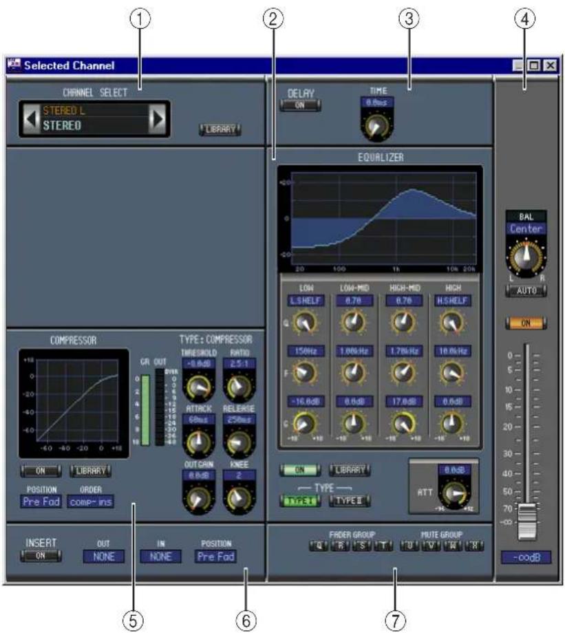
This is the Selected Channel window for the Stereo Out.
text_image
Selected Channel CHANNEL SELECT STERED L STERED LIBRARY DELAY ON TIME 0.0ns EQUALIZER COMPRESSOR TYPE: COMPRESSOR TIMESHOLD -0.0dB RATIO 2.5:1 ATTACK 68ms RELEASE 250ms OUT CAIN 0.0dB KNEE 2 ON LIBRARY POSITION Pre Fod ORDER comp-ins INSERT IN NONE Position Pre Fod FROER GROUP MUTE GROUP -0.0dB① CHANNEL SELECT section
Channels can be selected by clicking the Channel ID and choosing from the list that appears, or by clicking the left and right Channel Select buttons. The long channel name is displayed below the Channel ID. The LIBRARY button opens the Channel Library window.
② EQUALIZER section
This section contains the EQ controls and display graph for the Stereo Out. It's layout is identical to the EQUALIZER section for Input Channels. See "EQUALIZER section" on page 11 for more information.
③ DELAY section
This section contains the delay controls for the Stereo Out. The rotary control is used to set the delay time, and the ON button turns the Delay function on and off.
④ Balance & level section
This section contains the balance control, AUTO and ON buttons, and channel fader for the Stereo Out.
⑤ COMPRESSOR section
This section contains the Compressor controls and display graph for the currently selected Stereo Out. Its layout is identical to the COMPRESSOR section for Input Channels except there is no LINK button. See “COMPRESSOR section” on page 11 for more information.
⑥ INSERT section
This section contains the Insert parameters for the Stereo Out. The INSERT button turns the Insert on and off. The OUT and IN parameters are used to specify the insert out destination and insert in source respectively. The POSITION parameter is used to specify the position of the Insert in the signal path.
⑦ FADER GROUP & MUTE GROUP section
This section contains the Fader and Mute group functions for the Stereo Out. Use the FADER GROUP buttons to add the Stereo Out to Fader groups, and use the MUTE GROUP buttons to add it to Mute groups.
Remote Channels
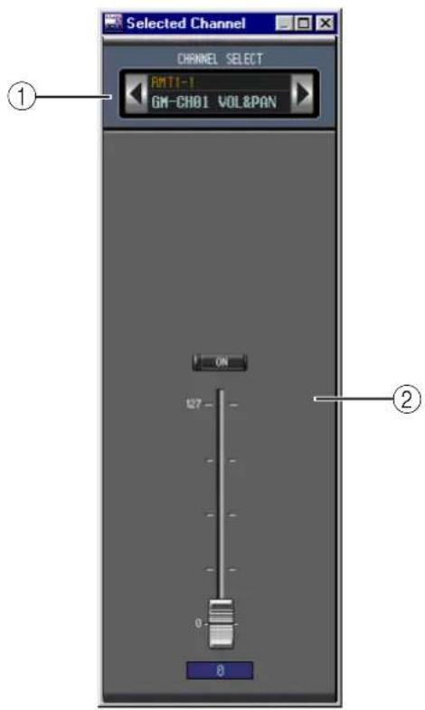
This is the Selected Channel window for the Remote Channels.
① CHANNEL SELECT section
Channels can be selected by clicking the Channel ID and choosing from the list that appears, or by clicking the left and right Channel Select buttons. The long channel name is displayed below the Channel ID.
② Remote Channel Level section
This section contains the ON button and the channel fader for the currently selected Remote Channel.
Note: When the remote target setting on the 02R96 is set to anything other than User Defined, the ON buttons and channel faders have no effect, and the name of the specified target is displayed below the channel ID.
text_image
Selected Channel CHANNEL SELECT RMT1-1 GM-CH01 VOL&PAN ① ② ON 127 0 84 Library Window
The Library window allows you to control and manage 02R96 Scenes and libraries. In addition, Scenes and libraries can be saved to disk on your computer.
The Library window provides access to the following libraries:
| Library How to Open | |
| Scene Choose Library from the Windows menu | |
| Channel | LIBRARY buttons on the Selected Channel window |
| Equalizer | |
| Gate | |
| Compressor | |
| Effects LIBRARY button on the Effects Editor window | |
| Input Patch | LIBRARY buttons on the Patch Editor window |
| Output Patch | |
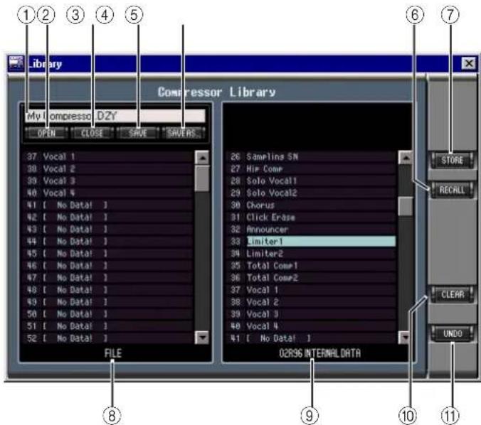
The layout of the Library window is the same regardless of which library is selected (the Compressor Library is shown below). The Library window consists of two panes. The pane on the left displays a list of memories in the currently open Library file. The pane on the right displays a list of memories in the 02R96.
Memories can be copied between the 02R96 and Library file by dragging them between the panes. Memories can be copied or sorted within the 02R96 or Library file by dragging them within the same pane. When a memory is dropped on top of another memory, it's copied. When a memory is dropped between two memories, it's moved (i.e., sorted). Memory contents can be swapped by holding down the Shift key while dragging. In all cases, the contents of the destination memory are overwritten. To edit a memory title, click and then type.
text_image
Library My I compresso DZY OPEN CLOSE SAVE SHOURS 37 Vocal 1 38 Vocal 2 39 Vocal 3 40 Vocal 4 41 [ No Data1 ] 42 [ No Data1 ] 43 [ No Data1 ] 44 [ No Data1 ] 45 [ No Data1 ] 46 [ No Data1 ] 47 [ No Data1 ] 48 [ No Data1 ] 49 [ No Data1 ] 50 [ No Data1 ] 51 [ No Data1 ] 52 [ No Data1 ] FILE 02R96 INTERNALDATA 26 Samplina SN 27 Hip Comr 28 Solo Vocal1 29 Solo Vocal2 30 Chorus 31 Click Erase 32 Announcer 33 Limiter1 34 Limiter2 35 Total Comr1 36 Total Comr2 37 Vocal 1 38 Vocal 2 39 Vocal 3 40 Vocal 4 41 [ No Data1 ] STORE RECALL CLEAR UNDO ① ② ③ ④ ⑤ ⑥ ⑦ ⑧ ⑨ ⑩ ⑪① File name
This is the file name of the currently open Library file.
② OPEN button
This button is used to open Library files.
③ CLOSE button
This button is used to close the currently open Library file.
④ SAVE button
This button is used to save the currently open Library file.
⑤ SAVE AS button
This button is used to save the currently open Library file with a different name.
⑥ RECALL button
This button is used to recall the selected memory.
⑦ STORE button
This button is used to store to the selected memory.
⑧ FILE pane
This pane displays the memories in the currently open Library file.
⑨ 02R96 INTERNAL DATA pane
This pane displays the 02R96 memories in the currently selected Library.
⑩ CLEAR button
This button clears the contents of the selected memory.
⑪ UNDO button
This button undoes the last recall, store, copy, clear, swap, or titling operation.
5 Patch Editor Window
The Patch Editor window is used to patch Inputs, Outputs, Inserts, Effects, and Direct Outs. It consists of five pages, which are selected by clicking the tabs along the top of the window. To open the Patch Editor window, choose Patch Editor from the Windows menu.
Input Patch Page
text_image
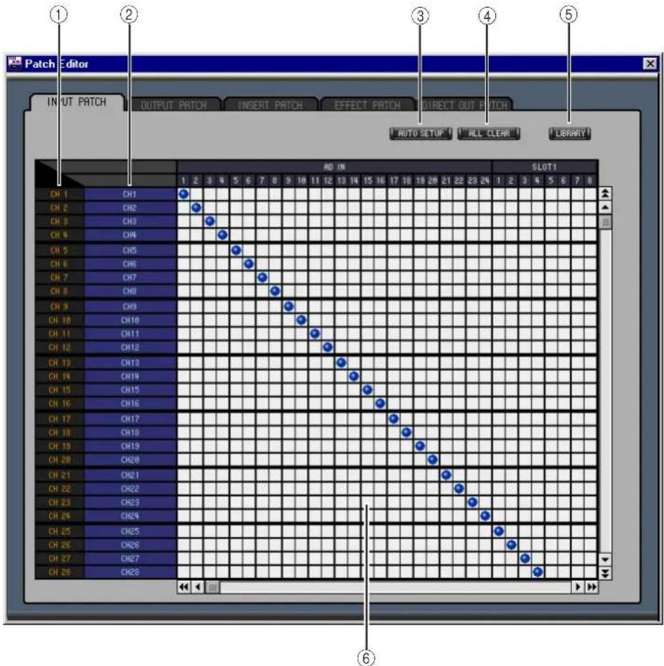
Patch Editor INPUT PATCH OUTPUT PATCH INSERT PATCH EFFECT PATCH DIRECT OUT PATCH AUTO SETUP ALL CLEAR LIBRARY AD IN SLUT1 CH 1 CH1 CH2 CH3 CH4 CH5 CH6 CH7 CH8 CH9 CH10 CH11 CH12 CH13 CH14 CH15 CH16 CH17 CH18 CH19 CH20 CH21 CH22 CH23 CH24 CH25 CH26 CH27 CH28 ① ② ③ ④ ⑤ ⑥① Channel IDs
These are the Channel IDs.
② Long channel names
These are the Channel long names. To edit a name, click it and type.
③ AUTO SETUP button
Clicking this button sets the patches on this page to their initial values.
④ ALL CLEAR button
This button clears all patches on this page.
⑤ LIBRARY button
This button opens the Input Patch Library window.
⑥ Patchbay
The patchbay is used to patch input ports to Input Channels. Active patches are indicated by a blue dot. To make a patch, click a square. To unpatch, click a blue dot.
Output Patch Page
text_image
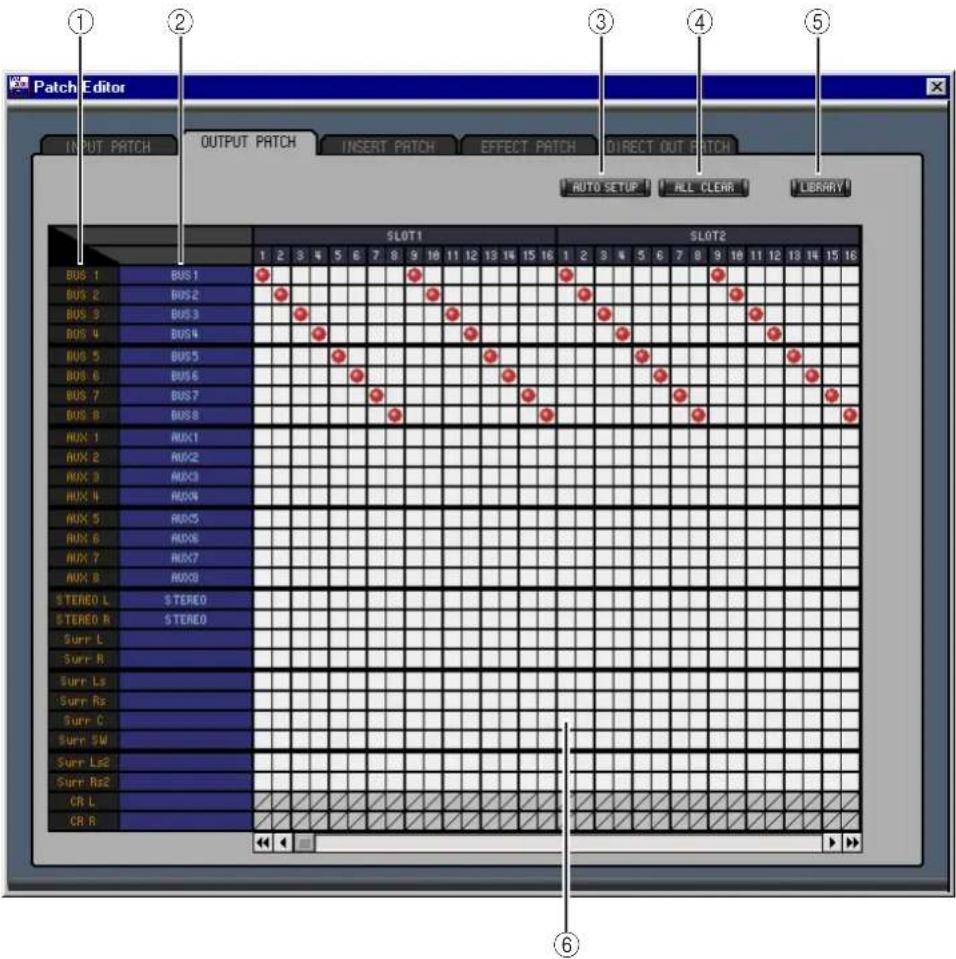
Patch Editor INPUT PATCH OUTPUT PATCH INSERT PATCH EFFECT PATCH DIRECT OUT PATCH AUTO SETUP ALL CLEAR LIBRARY SLOT1 SLOT2 1 2 3 4 5 6 7 8 9 10 11 12 13 14 15 16 1 2 3 4 5 6 7 8 9 10 11 12 13 14 15 16 BUS 1 BUS 1 BUS 2 BUS 2 BUS 3 BUS 3 BUS 4 BUS 4 BUS 5 BUS 5 BUS 6 BUS 6 BUS 7 BUS 7 BUS 8 BUS 8 AUX 1 AUX1 AUX 2 AUX2 AUX 3 AUX3 AUX 4 AUX4 AUX 5 AUX5 AUX 6 AUX6 AUX 7 AUX7 AUX 8 AUX8 STEREO L STEREO STEREO R STEREO Surr L Surr R Surr Ls Surr Rs Surr C Surr SW Surr Ls2 Surr Re2 CR L CR R << <<① Channel IDs
These are the Channel IDs.
② Long channel names
These are the Channel long names. To edit a name, click it and type.
③ AUTO SETUP button
Clicking this button sets the patches on this page to their initial values.
④ ALL CLEAR button
This button clears all patches on this page.
⑤ LIBRARY button
This button opens the Output Patch Library window.
⑥ Patchbay
The patchbay is used to patch output ports to Output Channels. Active patches are indicated by a red dot. To make a patch, click a square. To unpatch, click a red dot.
Insert Patch Page
text_image
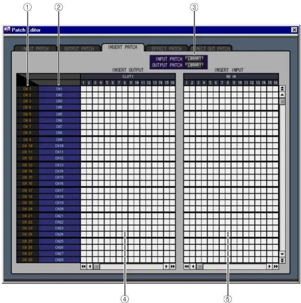
Patch Editor INPUT PATCH OUTPUT PATCH INSERT PATCH EFFECT PATCH DIRECT OUT PATCH INPUT PATCH !LIBRARY! OUTPUT PATCH !LIBRARY! INSERT OUTPUT SLOT1 RD IN CH 1 CH1 CH 2 CH2 CH 3 CH3 CH 4 CH4 CH 5 CH5 CH 6 CH6 CH 7 CH7 CH 8 CH8 CH 9 CH9 CH 10 CH10 CH 11 CH11 CH 12 CH12 CH 13 CH13 CH 14 CH14 CH 15 CH15 CH 16 CH16 CH 17 CH17 CH 18 CH18 CH 19 CH19 CH 20 CH20 CH 21 CH21 CH 22 CH22 CH 23 CH23 CH 24 CH24 CH 25 CH25 CH 26 CH26 CH 27 CH27 CH 28 CH28 ①②③④⑤① Channel IDs
These are the Channel IDs.
② Long channel names
These are the Channel long names. To edit a name, click it and type.
③ LIBRARY buttons
These buttons open the Input and Output Patch Library windows.
④ Insert Out Patchbay
This patchbay is used to patch output ports to the Insert Outs of Input Channels, Bus Outs, Aux Sends, and the Stereo Out. Active patches are indicated by a red dot. To make a patch, click a square. To unpatch, click a red dot.
⑤ Insert In Patchbay
This patchbay is used to patch input ports to the Insert Ins of Input Channels, Bus Outs, Aux Sends, and the Stereo Out. Active patches are indicated by a blue dot. To make a patch, click a square. To unpatch, click a blue dot.
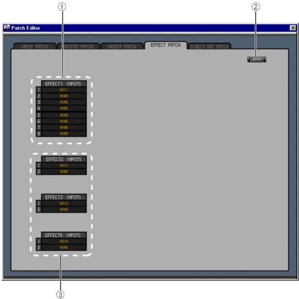
Effect Patch Page
text_image
Patch Editor INPUT PATCH OUTPUT PATCH INSERT PATCH EFFECT PATCH DIRECT OUT PATCH LIBRARY EFFECT1 INPUTS 1 RCK1 2 NONE 3 NONE 4 NONE 5 NONE 6 NONE 7 NONE 8 NONE EFFECT2 INPUTS 1 RCK2 2 NONE EFFECT3 INPUTS 1 RCK3 2 NONE EFFECT4 INPUTS 1 RCK4 2 NONE① Effects processor #1 inputs These parameters are used to select input sources for internal effects processors #1.
② LIBRARY button
This button opens the Input Patch Library window.
③ Effects processors 2–4 inputs
These parameters are used to select input sources for internal effects processors 2–4.
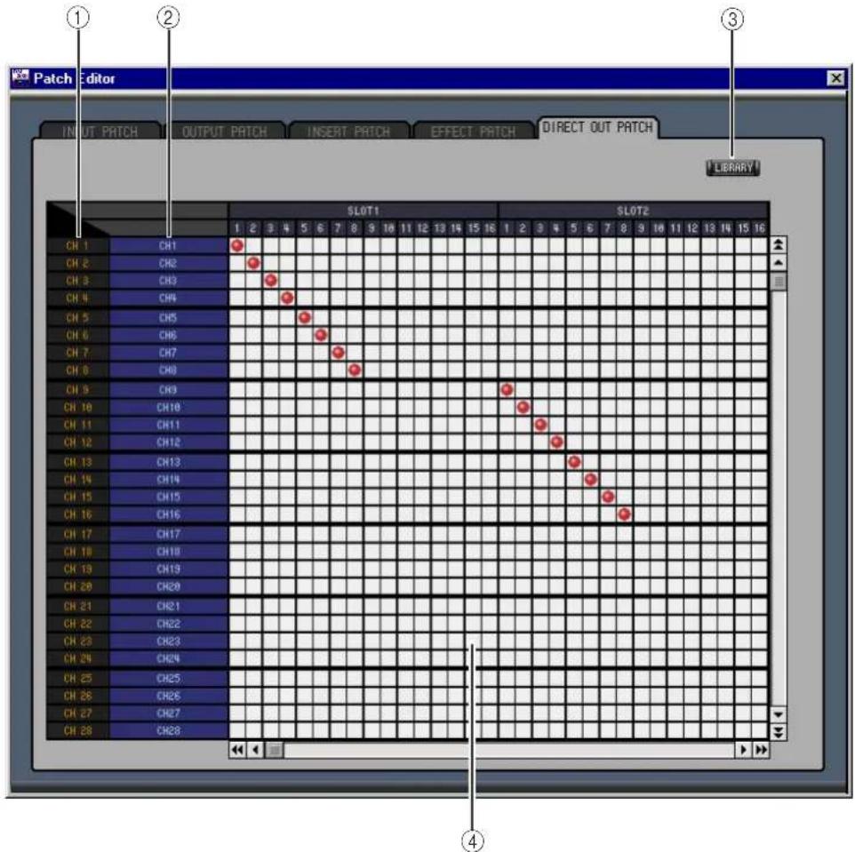
Direct Out Patch Page
text_image
Patch Editor INPUT PATCH OUTPUT PATCH INSERT PATCH EFFECT PATCH DIRECT OUT PATCH LIBRARY SLOT1 SLOT2 ① ② ③ CH 1 CH1 CH 2 CH2 CH 3 CH3 CH 4 CH4 CH 5 CH5 CH 6 CH6 CH 7 CH7 CH 8 CH8 CH 9 CH9 CH10 CH10 CH11 CH11 CH12 CH12 CH13 CH13 CH14 CH14 CH15 CH15 CH16 CH16 CH17 CH17 CH18 CH18 CH19 CH19 CH20 CH20 CH21 CH21 CH22 CH22 CH23 CH23 CH24 CH24 CH25 CH25 CH26 CH26 CH27 CH27 CH28 CH28① Channel IDs These are the Channel IDs.
② Long channel names These are the Channel long names. To edit a name, click it and type.
③ LIBRARY button This button opens the Output Patch Library window.
④ Patchbay The patchbay is used to patch output ports to the Direct Outs. Active patches are indicated by a red dot. To make a patch, click a square. To unpatch, click a red dot.
6 Surround Editor Window
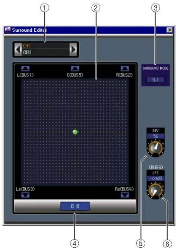
The Surround Editor window allows you to edit the surround pan position of the currently selected Input Channel. To open the Surround Editor window, choose Surround Editor from the Windows menu.
text_image
Surround Editor CH1 CH1 L(BUS 1) C(BUS 5) R(BUS 2) SURROUND MODE 5.1 DIV 56 (BUS 6) LFE -cod8 Ls(BUS 3) Rs(BUS 4) C C ① ② ③ ④ ⑤ ⑥① CHANNEL SELECT section
Channels can be selected by clicking the Channel ID and selecting from the list that appears, or by clicking the left and right Channel Select buttons. The long channel name is displayed below the Channel ID. To edit the name, click it and type.
② Surround pan graph
The green dot on this graph indicates the surround pan position for the currently selected Input Channel. The surround pan can be set by dragging the dot.
③ SURROUND MODE indicator
This indicates the currently selected Surround mode: STEREO, 3-1, or 5.1.
④ Surround pan position
This is the current surround pan position.
⑤ DIV control
This rotary control sets the amount of divergence (i.e., how the Center signal is fed to the Left, Right, and Center channels).
⑥ LFE control
This rotary control sets the level of the LFE channel.
7 Effect Editor Window
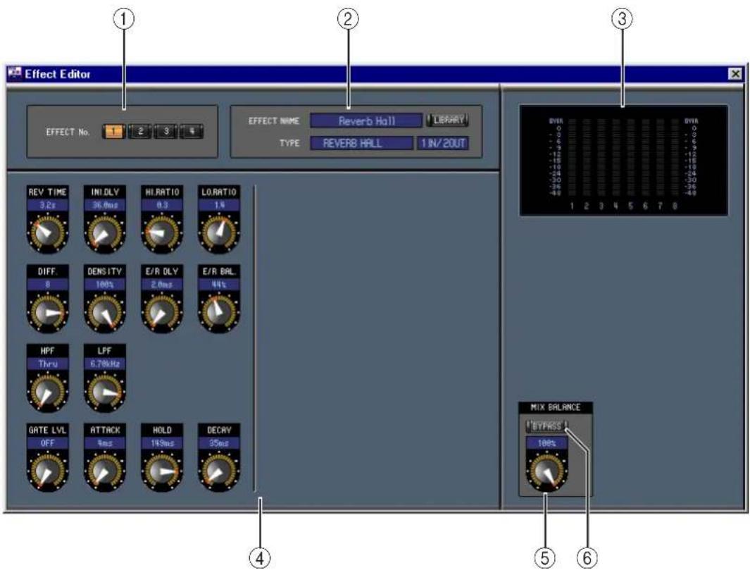
The Effect Editor window allows you to edit the internal effects processors. To open the Effect Editor window, choose Effect Editor from the Windows menu.
text_image
Effect Editor EFFECT No. 1 2 3 4 EFFECT NAME Reverb Hall LIBRARY TYPE REVERB HALL 1 IN/2OUT REV TIME INI DLY HI RATIO LO RATIO 3.8s 36.0ms 0.3 1.4 DIFF DENSITY E/R DLY E/R BAL 8 100% 2.0ms 44% HPF LPF Thru 6.70kHz GATE LVL ATTACK HOLD DECRY OFF 9ms 14.9ms 35ms MIX BALANCE 1 BYPASS 100% 1 2 3 4 5 6 7 8 0 -1 -2 -3 -4 -5 -6 -7 -8 -9 -10 -11 -12 -13 -14 -15 -16 -17 -18 -19 -20 -21 -22 -23 -24 -25 -26 -27 -28 -29 -30 -45 1 2 3 4 5 6 7 8 ① ② ③ ④ ⑤ ⑥① Effects processor select
These buttons are used to select the internal effects processors.
② Effect select section
The EFFECT NAME, TYPE, and IN/OUT are the name, type and I/O configuration of the effect recalled to the currently selected effects processor. To edit the EFFECT NAME, click it and type. The LIBRARY button opens the Effects Library window.
③ Meters
These are output meters for the currently selected effects processor.
④ Effect parameter section
This section contains the various effects controls, buttons, and displays. Its layout depends on the selected effect type.
⑤ MIX BALANCE control
This control is used to adjust the balance between the wet and dry signals. When set to 0, only the dry signal is heard. When set to 100, only the wet signal is heard.
⑥ BYPASS button
This button is used to bypass the currently selected effects processor.
8 Timecode Counter Window
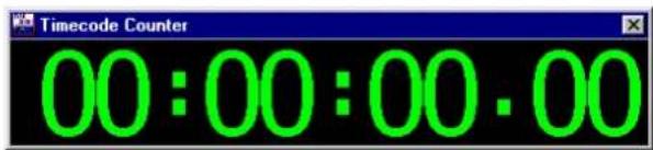
The Timecode Counter window displays the current timecode position in hours, minutes, seconds, and frames, or measures, beats, and MIDI clocks, depending on the specified timecode source. It works in unison with the timecode counters on the 02R96 Automix Main and Memory pages.
text_image
Timecode Counter 00:00:00.009 Keyboard Shortcuts
File Menu
| Windows Macintosh Action | ||
| CTRL+N | ⌘-N | Creates a new Session |
| CTRL+O | ⌘-O | Opens a previously saved Session |
| CTRL+S | ⌘-S | Saves the current Session |
Windows Menu
| Windows Macintosh Action | ||
| CTRL+W | ⌘-W | Closes the foremost window except the Console window |
| CTRL+ALT+W | ⌘-Option-W | Closes all windows except the Console window |
| CTRL+1 | ⌘-1 | Opens the Selected Channel window |
| CTRL+2 | ⌘-2 | Opens the Library window |
| CTRL+3 | ⌘-3 | Opens the Patch Editor window |
| CTRL+4 | ⌘-4 | Opens the Surround Editor window |
| CTRL+5 | ⌘-5 | Opens the Timecode Counter window |
| CTRL+6 | ⌘-6 | Opens the Effect Editor window |
Index
Numerics
02R96 INTERNAL DATA pane 19
A
ALL CLEAR button 20, 21
All Lib, synchronization 3
ATT control 12, 14, 16
AUTO button 6, 7, 8, 11, 13, 14, 16
AUTO SETUP button 20, 21
Aux Send masters
console window 8
selected channel window 14
Aux Sends
console window 6
selected channel window 11
B
BAL control 16
Bus Outs
console window 8
selected channel window 12
BYPASS button 26
C
Channel fader 6, 7, 8, 9, 11, 13, 14, 16, 17
Channel library 18
Channel meter 6, 8
CHANNEL SELECT 10, 12, 14, 16, 17, 25
Channel Select, preference 2
CLEAR button 19
CLOSE button 18
COMP button 5, 8
COMPRESSOR 11, 13, 14, 16
Compressor curve 5, 8, 11, 13, 14, 16
Compressor library 18
Configuring Studio Manager 1
Confirmation, preference 2
Console Device ID, preference 2
Console window 4
Console->PC, channel select 2
Console->PC, layer select 2
Console->PC, synchronization 3
Creating new sessions 3
D
DELAY button 5, 8
Delay parameter 6, 8
DELAY section 11, 12, 14, 16
DIRECT button 5, 11
Direct Out parameter 5, 11
Direct out patch page 24
DIV control 25
E
Effect editor window 26
EFFECT NAME 26
EFFECT No. 26
Effect patch page 23
EFFECT TYPE 26
Effects library 18
EQ button 5,8
EQ curve 5, 8, 11, 12, 14, 16
EQ library 18
EQUALIZER section 11, 12, 14, 16
Exiting Studio Manager 1
F
F.PAN button 11
FADER GROUP buttons 12, 13, 15, 17
FILE pane 19
G
GATE 11
GATE button 5
Gate curve 11
Gate library 18
Gate open/close indicators 5
Gate threshold 5
|
Input Channels
console window 5
selected channel window 10
INPUT PATCH 10
Input Patch library 18
Input patch page 20
Input port 1
INSERT button 5, 8, 11, 13, 15, 17
Insert patch page 22
INSERT section 11, 13, 15, 17
K
Keyboard shortcuts 28
L
Launching Studio Manager 1
LAYER buttons 7
Layer Select, preference 2
LFE control 6, 25
LIBRARY button 10, 12, 14, 16, 20, 21, 22, 23, 24
Library window 18
M
Master section 7
Meters 7, 26
MIX BALANCE control 26
MUTE GROUP buttons 12, 13, 15, 17
N
New sessions 3
O
Offline indicator 1
OMS MIDI Setup 1
OMS Studio Setup 1
ON button 6, 7, 8, 9, 11, 13, 14, 16, 17
Online indicator 1
OPEN button 18
Opening sessions 3
Output channels 8
Output Patch library 18
Output patch page 21
Output port 1
P
Pair icon 12, 13, 15
PAN CONTROL 7
PAN control 6, 11
Pan/Aux Send display 6
Patch confirmation 2
Patch editor window 20
Patchbay 20, 21, 22, 24
Patching 20
PC->Console, channel select 2
PC->Console, layer select 2
PC->Console, synchronization 3
PHASE button 5, 11
Ports, selecting 1
Pre/post buttons 11
Q
Quitting Studio Manager 1
R
RECALL button 19
Recall confirmation 2
Remote Channels
console window9
selected channel window 17
Resynchronizing Studio Manager 3
ROUTING buttons 5, 11
Run MIDI in background 1
S
SAVE AS button 19
SAVE button 19
Saving sessions 3
Scene library 18
SELECT button 6, 7, 8, 9
Sessions 3
Setup window 2
Shortcuts, keyboard 28
SOLO button 6, 8, 11, 13, 14
SOURCE parameter 5
Starting Studio Manager 1
STEREO button 5, 7, 8, 11
Stereo Out
console window 7
selected channel window 16
STORE button 19
Store confirmation 2
SURR button 7
Surround editor window 25
SURROUND MODE indicator 25
Surround pan graph 25
Surround pan position 25
Synchronizing Studio Manager 3
T
Timecode counter window 27
TO STEREO section 13
TYPE I button 11, 12, 14, 16
TYPE II button 11, 12, 14, 16
U
UNDO button 19
Y
Yamaha Web Site i
