
ESPRIMO Mobile U9200 - Laptop FUJITSU SIEMENS - Free user manual and instructions
Find the device manual for free ESPRIMO Mobile U9200 FUJITSU SIEMENS in PDF.


| Brand | Fujitsu Siemens |
| Model | ESPRIMO Mobile U9200 |
| Product Type | Notebook (Laptop) |
| Dimensions (W x D x H) | 300 mm x 223 mm x 37.5 mm |
| Weight (approx.) | 1.9 kg |
| Operating System | Windows XP or Windows Vista (pre-installed) |
| Processor | Intel Core (exact model varies by configuration) |
| Main Memory (RAM) | Up to 4 GB DDR2 (dual-channel support) |
| Hard Disk Drive | Internal SATA hard disk (removable) |
| Optical Drive | CD/DVD burner (removable) |
| Display | LCD screen (exact size not specified) |
| Graphics | Integrated (exact chipset not specified) |
| Audio | Integrated audio controller, stereo speakers, headphone/microphone jacks |
| Camera | Integrated VGA camera (webcam) |
| Connectivity | WLAN, Bluetooth, UMTS (optional), LAN (Ethernet), Modem |
| Ports | USB 2.0 (several), Monitor (VGA), S-Video out, ExpressCard slot, Memory card reader |
| Battery | Li-Ion, 11.1 V, 5200 mAh (removable) |
| Power Adapter | 20 V, 4.5 A (max) |
| Security | Kensington Lock, BIOS password protection |
| Expansion Options | Second battery/travel battery, port replicator |
Frequently Asked Questions - ESPRIMO Mobile U9200 FUJITSU SIEMENS
User questions about ESPRIMO Mobile U9200 FUJITSU SIEMENS
0 question about this device. Answer the ones you know or ask your own.
Ask a new question about this device
Download the instructions for your Laptop in PDF format for free! Find your manual ESPRIMO Mobile U9200 - FUJITSU SIEMENS and take your electronic device back in hand. On this page are published all the documents necessary for the use of your device. ESPRIMO Mobile U9200 by FUJITSU SIEMENS.
USER MANUAL ESPRIMO Mobile U9200 FUJITSU SIEMENS
ProfessionalNotebookEnglish
EasyGuide
ESPRIMOMobileSeries

Arethere...
...anytechnicalproblemsorotherquestionsthatyouwouldlikehelpwith?
Pleasecontact:
- ourHotline/HelpDesk(refertotheenclosedHelpDeskListorgoto: "www.fujitsu-siemens.com/support/")
•yoursalespartner
•yoursalesoffice
AdditionalinformationiscontainedintheHelpDesklistandthe"Warranty"manual.The "Warranty" manual can be found on the supplied "Drivers & Utilities" CD/DVD.
Latestinformationonourproducts,tips,updatesetc.canbefoundonour websiteat:" www.fujitsu-siemens.com"
ThismanualwasproducedbyXeroxGlobalServices
Publishedby
FujitsuSiemensComputersGmbH
AG09/07
Edition2
Orderno.:A26391-K230-Z120-1-7619
ESPRIMOMobileSeries
EasyGuide
YourESPRIMOMobile1
Importantnotes 3
Portsandoperati ngelements 4
Removing and installing components during servicing 23
Technicaldat a 30
Index 31
Adobe and Acrobat are trademark of Adobe Systems Incorporated and may be protected in certain countries.
The Bluetooth trademarks are the property of Bluetooth SIG, Inc., U.S.A. and licensed to Fujitsu Siemens Computers GmbH.
Intelisaregisteredtrademark, CoreisattrademarkofIntelCorporation, USA.
KensingtonandMicroSaverareregisteredtrademarksofACCOWorldCorporation.
Macrovision is a trademark of Macrovision Corporation, USA.
Microsoft, MS, MS-DOS, Windows, Vista and Windows NT are registered trademarksofMicrosoftCorporation.
Allothertrademarksreferencedaretrademarksorregisteredtrademarksoftheir respectiveowners,whoseprotectedrightsareacknowledged.
Copyright©FujitsuSiemensComputersGmbH2007
Allrightsreserved, including rightsoftranslation, reproductionbyprinting, copying or similar methods, inpartorinwhole.
Intheeventofviolations, perpetratorswillbelieabletoprosecutionfordamages.
All rights reserved, including rights created by patent grant or registration of a utility model or design.
Subject to availability and technical modifications.
Contents
YourESPRIMOMobile 1
Notationalconventions....2
Importantnotes 3
Portsandoperatingelements 4
ESPRIMOMobileU9200 5
ESPRIMOMobileM9400 6
ESPRIMOMobileD9500 7
Switchingonthenotebook....8
Switching off the Notebook 9
Statusindicators 10
Keycombinations 12
Camera (depending on notebook model) 14
Removing and installing the battery 15
Removing the battery 15
Inserting the battery 15
Removing/fitting the second battery/travel battery (optional) 16
Installingthebattery 16
Removing the battery 18
SIM card 20
Inserting the SIM card 20
Removing the SIM card 21
Radio components: Wireless LAN/Bluetooth/UMTS 22
Switching the radio components on and off 22
Removing and installing components during servicing 23
Notesoninst allingandremovingboardsand components 23.
Harddisk 24
Removingth e hard disk 24
Installing the hard disk 25
Removing and installing memory modules 26...
Removingt he cover 27
Removing memory modules 27
Installing a memory module 27
Attaching the cover 28
Removing and installing the optical drive 29....
Removing the optical drive 29
Installing the optical drive 29.
Technical data 30
Notebook 30
Battery 30
Mains adapter 30
Index 31
YourESPRIMOMobile
...offersyouinnovativetechnologyandergonomicdesign. This makes your notebook reliable, convenient mobile PC.
Yournotebookisavailableinseveraldifferentversions.Mostofthesectionsinthismanual apply to all models - any differences are pointed out separately. Some of the illustrations and featuresinthismanualmaydifferfromyourmodelandareforguidanceonly.
Your Windows operating system is already pre-installed and optimally configured. That means you're ready to start when you switch on your notebook for the first time.
Your notebook features the very latest technology so that you get the best performance from yourcomputingexperience.Dependingonwhichmodelyouown,youhaveaccessto:
- upto 4 GB of main memory (RAM)
•aCD/DVDburner-DVDforwatch ingDVDmoviesandwritingyourownCDsandDVDs
•anS-Videooutsocketforconnectingyournotebooktoyourtelevision
•anintegralcameraforsnaps hotsandvideochat(dependingonmodel) - severalUSBports,providingsimpleexpansionoptionsforgamepads,printersandmore
•aninternalmodemforconnect ingtothelnternet
• a memory card slot for transferring digital photos, music and videos quickly onto your notebook
•anExpressCardslotforoperat inganExpressCard/34orExpressCard/54 (dependingonyourvariantoft hedevice)
• a SIM card slot that can be used to operate a SIM card (depending on model)
•anintegratedaudiocontrolle randtwostereospeakers. Youcanevenconnecta microphoneandexternalspea kersforevenbettersoundperformance.
With the user-friendly BIOS-Setup you can control the hardware of your notebook and protect your systembetteragainstunauthorisedaccessbyusingthepowerfulpasswordfeatures.
Thisoperatingmanualdescribeshowtogetyournotebookupandrunningandhowtouseit.
Furtherinformationonthisnotebookisprovided:
- Inthe"ProfessionalNotebook"OperatingManual
- Inthe"Safety" and"Warranty" manuals
•inthedocumentationoftheoperatingsystem
•intheinformationfiles(e.g. *. TXT,*.DOC,*.WRI,*.HLP,*.PDF)

You can find information on accessories for your Notebook at "www.fujitsu-siemens.com/accessories".
Notationalconventions
| Payparticularattentiontotextmarkedwiththissymbol.Failuretoobserve thiswarningwillendangeryourlife,willdamagethedeviceorleadtoloss ofdata.Thewarrantywillbeinvalidatedifyoucausedefectsinthedevice throughfailuretotakenoticeofthiswarning | |
| indicatesimportantinformat ionthatisrequiredtousethedeviceproperly. | |
| ▶ | indicatesanactivitythatmustbeperformedintheordershown |
| ↳ | indicatesaresult |
| Thisstyle | flagsdataenteredusingthekeyboardinaprogramdialogorcommand line, e.g. your password (Name123) or a command to launch a program (start.exe) |
| Thisstyle | referstoinformationdisplayedbyaprogramonthescreen,e.g.: Installationiscompleted |
| Thisstyle | isfor•termsandtextsinasoftwar euserinterface,e.g.:ClickSave.• names of programs or files, e.g. Windows or setup.exe. |
| "Thisstyle" | isfor•cross-referencestoanothersection,e.g."Safetyinformation"•cross-referencestoanexternalsource,e.g.awebaddress:Formore information,goto" www.fujitsu-siemens.com"•indicatesnamesofCDsandDVDsaswellasnamesandtitlesofother materials, e.g.: "CD/DVD Drivers & Utilities" or "Safety" manual |
| Abc | referstoakeyonthekeyboard,e.g.: F10 |
| Thisstyle | flags concepts and text that are emphasised or highlighted, e.g.: Do not switchoffdevice |
Importantnotes

Takenoteofthesafetyhintsprovidedinthe"Safety"manual,inthe"Professional Notebook"operatingmanualandinthismanual.
Portsandoperatingelements
Thischapterpresentstheindividualhardwarecomponents. Thiswillprovideyouwithan overviewoftheportsandoperatingelementsonthenotebook.
Please familiarise yourself with these components before you start working with your notebook.
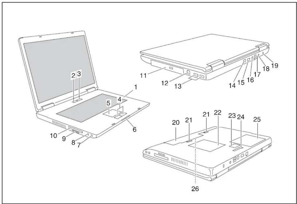
ESPRIMOMobileU9200
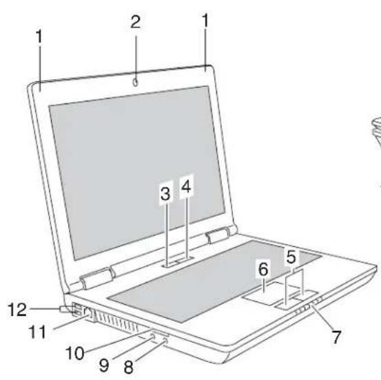
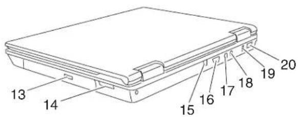
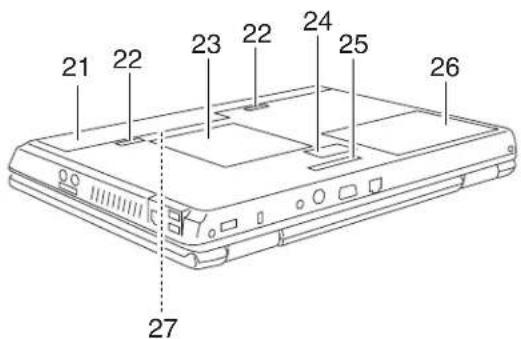
1=Microphone
2 = Camera
3 = ON/OFF switch for radio components
4=ON/OFFswitch
5=Touchpadbuttons
6=Touchpad
7=Statusindicators
8=Headphoneport
9=Microphoneport
10 =Memorycardslot
11 =Modemport
12 = USBports
13 = Opticaldrive
14 = ExpressCard slot for ExpressCard/34
15 = LAN port
16 = Monitor port
17 = S-Videoout socket
18 = DCjack (DCIN)
19 = KensingtonLock
20 = USB port
21 = Battery
22 = Batteryrelease latch
23 = Service compartment (memory)
24 = Connector for second battery (travelbattery)
25 = Connection for port replicator
26 = Service compartment (hard disk)
27 = SIMcardslot (concealedint he battery compartment)
ESPRIMOMobileM9400
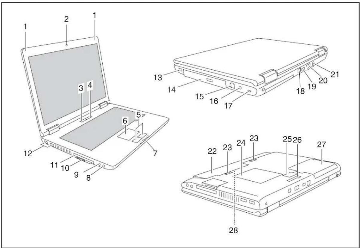
1=Microphone
2=Camera(optional)
3=ON/OFFswitc hforradiocomponents
4=ON/OFFswitch
5=Touchpadb uttons
6=Touchpad
7=Statusin dicators
8=Headphoneport
9=Micropho neport
10=Memorycardslot
11=Expres sCardslotforExpressCard/34 andExp ressCard/54
12=USBports
13=USBpo rt
14=Opticaldrive
15=Mode mport
16=DCjack(DCIN)
17=KensingtonLock
18=LANport
19=USBport
20=Monitorpo rt
21=S-Videoutsocket
22=Battery
23=Batteryreleaselatch
24=Servicec ompartment(memory)
25=Connectorforsecondbattery (travelbattery)
26=Connec tionforportreplicator
27=Servicecompartment(harddisk)
28=SIMca rdslot(concealedinthe batterycompartment)
ESPRIMOMobileD9500
1=Microphone
2=ON/OFFswitchforradiocomponents
3=ON/OFFswitc h
4=Touchpadbuttons
5=Touchpad
6=Statusindicators
7=Headphon eport
8=Microphoneport
9 = M e m odsloty c a
10=ExpressCardslotforExpressCard/34 andExpressCard/54
11=Optica I drive
12=Modemport
13=USBpo rts
14=LANport
15=Monitorport
16=S-Videooutsocket
17=USBport
18=DCjack(DCIN)
19=Kensingto nLock
20=Battery
21=Batteryr leaseelatch
22=Servicecompartment(memory)
23=Connecto rforsecondbattery (travel battery)
24=Connectionfor portreplicator
25=Servic ecompartment(harddisk)
26=SIMcardslot(concealedinthe batterycompartment)
Switchingonthenotebook
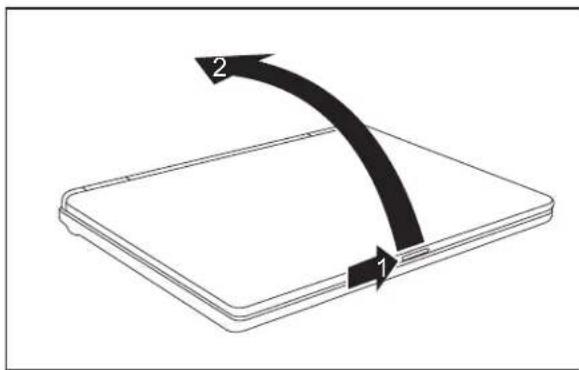
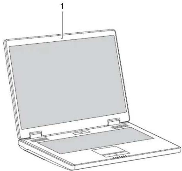
▶ Ondeviceswithareleasebutton:Slidethe releasebuttonindirectionofthearrow(1).
▶ LiftuptheLCDscreen(2).
natural_image
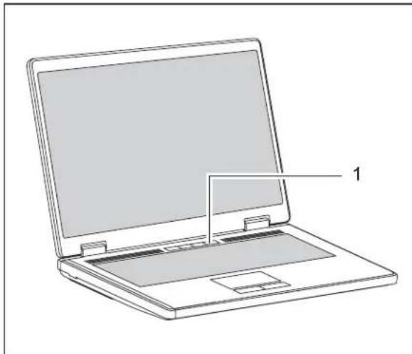
Line drawing of a laptop computer with a blank screen and labeled component '1' (no text or symbols on the device itself)▶ PresstheON/OFFswitch(1)foraround1 secondtoswitchthenotebookon.
→ Thepower-onindicat orlightsup.

WindowsXP
You can configure the power button with Start - (Settings) - Control Panel - Performance and Maintenance-Power Options-Advanced.
WindowsVista
You can configure the power button with Start - (Settings) - Control Panel-MobilePC-PowerOptions.
If you have assigned a password, you must enter this when requested to do so, in order to start the operating system. Further information can be found in the "Professional Notebook" operating manual, section entitled "Security functions".
SwitchingofftheNotebook
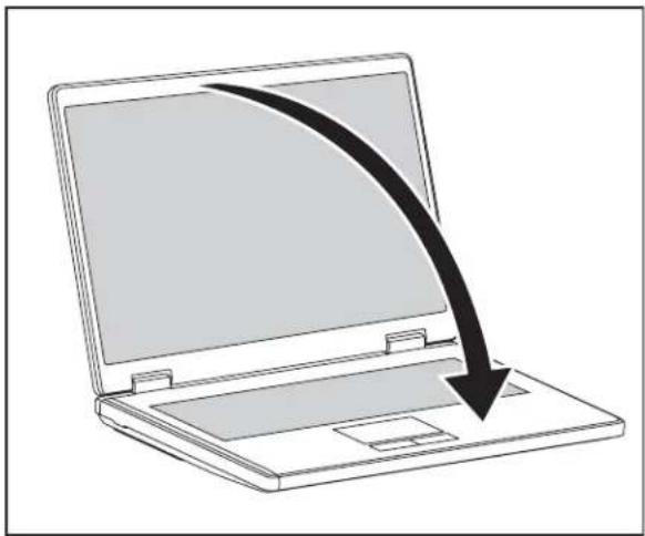
▶ Close all applications and shut down your operating system (please seeoperatingsystemmanual).
If thenotebook cannot beshutdown properly, press and hold the ON/OFF button for approximately four seconds. Thenotebook will switch off. Any unsaved datam may belost.
natural_image
Line drawing of a laptop with a downward arrow indicating download or exit (no text or symbols)▶ ClosetheLCDscreen.
Statusindicators
Thestatusindicatorsprovideinformationaboutthestatusofthepowersupply, thedrivesandthekeyboardfunctions.
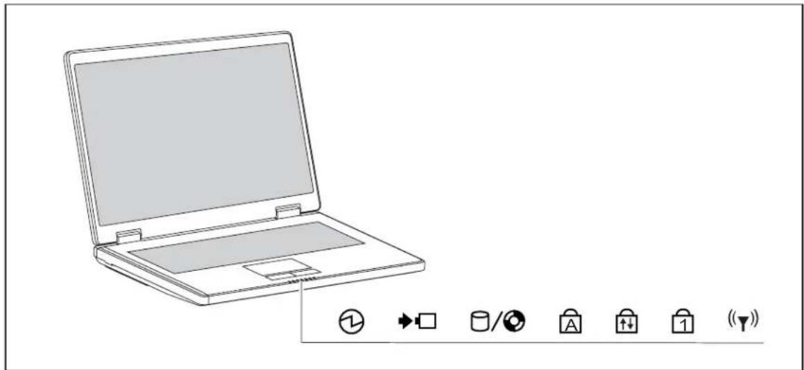

Power-onindicator

ScrollLockindicator
BatterychargingindicatorNumLockindicator

HarddiskindicatorRadiocomponentsindicator


CapsLockindicat or
Themeaningsofthesymbolsareasfollows:

Power-onindicator
- Indicatorislitup: Thenotebookisswitchedonandreadytouse.
- Indicatorflashes: Thenotebookisinstandbymode.
•Theindicatorisnotlitup:Thenotebookisswitchedoff.
Batterychargingindicator
Indicatorlightsup:thebatteryischarging.
Driveindicator
Indicatorlightsup:oneofthedrives(e.g.harddisk,CD/DVD)isbeingaccessed.

CapsLockindicator
Indicatorlightsup:theCapsLockkeyhas beenpressed.
Allthecharactersyoutypeappearinuppe rcase.Inthecaseofoverlaykeys,the characterprintedontheupperleftoft hekeyappearswhenthatkeyispressed.

ScrollLockindicator
Indicatorlightsup:thekeycombination Fn + ScrollLock has been pressed.
Theeffectthiskeyhasvariesfromprogrammetoprogramme.

NumLockindicator
Indicatorlightsup:thekeycombination Fn + Num has been pressed.
The numeric keypad is activated. In the case of overlay keys, the character printed ontheupperrightofthekeyappearswhenthatkeyispressed.
Radiocomponentsindicator
Indicator is illuminated: The radio components EasyLaunch key has been pressed. Oneormoreradiocomponentsareswitchedon.
Keycombinations
The key combinations described below apply when using Microsoft Windows operating systems. Some of the following key combinations may not function in other operating systems and with some devices drivers.
Keycombinationsareenteredasfollows:
▶ Press and hold the first key in the combination.
▶ While holding the first key down, press the other key or keys in the combination.

The key combination Ctrl + AltGr or Ctrl + Alt can be used on external keyboard that donotnotfeature a Fn key.
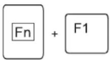
Switchingtheradiocomponentson/off
Use this key combination to start WirelessSelector. The radio components that have been activated in BIOS Setup can be switched on and off individually.

If the WirelessSelector program is not installed on your device, all of the radio components activated in the BIOS Setup can only be switched on and off together with Fn + F1.
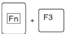
SwitchloudspeakersON/OFF
Thiskeycombinationswitchesyournotebook'sloudspeakersoffandon.
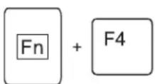
Decrease volume
Thiskeycombinationreducesthevolumeoftheintegratedloudspeakers.
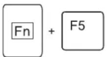
Increasesvolume
Thiskeycombinationincreases the volume of the integrated loudspeakers.
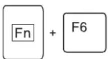
SwitchtouchpadON/OFF
Thiskeycombinationswitchesyournotebook'stouchpadoffandon.
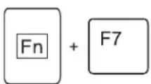
SwitchcameraON/OFF(dependingonyourdevice)
Usethiskeycombinationtoswitchthenotebook'sintegratedcameraonoroff.
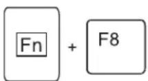
Decreasescreen brightness
Thiskeycombinationdecreasesthebrightnessofthescreen.
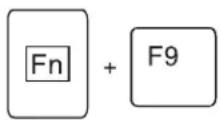
Increasescreenbrightness
Thiskeycombinationincreasesthebrightnessofthescreen.
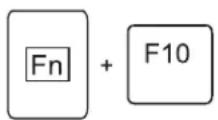
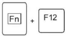
Toggleoutputscreen
Usethiskeycombinationtoselectwhichscreen(s)is/areusedfordisplay ifanexternalmonitorisconnected.
Youcanopttouse:
- justthenotebook'sLCDscreen
- justtheexternalmonitor
•boththeLCDscreenandtheexternalmonitor
Sleepmode
Use this key combination to activate the currently configured energy saving mode.
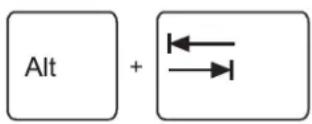
Switchingbetweenopenapplications
Usethiskeycombinationtoswitchbetweenseveralopenapplications.
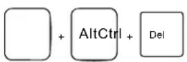
Performwarmreboot
Thiskeycombinationrestartsth enotebook.First,pressandhold boththe Ctrl and Alt keys,thenpressth e Del key.First,the TaskManagerwillbedisplayed .Youmustthenpressallthreekeys againtoreboot.
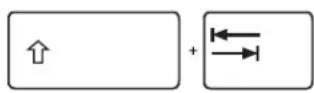
Backtab
Thiskeycombinationmovesthecu rsorbacktotheprevioustabular stop.

Key combinations using the Windows keys are detailed in the manual for your operating system.
Camera(dependingonnotebookmodel)
Your device is fitted with a VGA camera (1), which can also be used as a webcam.
natural_image
Line drawing of a laptop with blank screen and side panel, labeled with number 1 (no text or symbols on device)Removing and installing the battery

Only use batteries approved by Fujitsu Siemens Computers for your notebook.
Neveruseforcewheninsertingorremovingabattery.
Makesurethatnoforeignbodiesgetintothebatteryconnections.

The illustrations shown below may differ from your actual device. They are merely intended to clarify the principles involved.
Removingthebattery
▶ Switchthenotebookoffandpullthepowerplugoutofthemainssocket.
▶ ClosetheLCDscreen.
▶ Disconnect all cables connected to the notebook.
▶ Turnyournotebookoverandplaceit on a stable, sturdy, flat surface. If necessary, lay an anti-slipclothonthissurfaceto preventthenotebookfrombeingscratched.
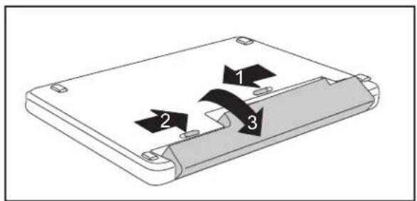
▶ Pushthebatterylockinthedirectionof thearrow(1)asfarasitwillgo.
▶ Slidethelockingdeviceinthedir ectionof thearrow(2)andholditinplace.
▶ Removethebatteryfromthenotebook inthedirectionofthearrow(3).
Insertingthebattery
natural_image
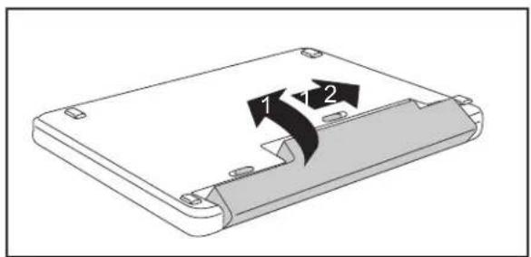
Diagram of a device casing with two labeled arrows indicating directional movement (no text or symbols present)▶ Placethebatteryinthebattery compartment sothatthecontactsenterfirst(1).
▶ Pushthebatteryintothebattery compartment until you feel it click into place.
▶ Pushthebatterylockinthedirectionof thearrow(2)uptothestop.
Removing/fittingthesecondbattery/travel battery(optional)

OnlyusebatteriesapprovedbyFujitsuSiemensComputersforyournotebook.
Neveruseforcewhenfittingorremovingabattery.
Makesurethatnoforeignbodiesgetintothebatteryconnections.
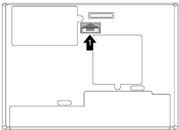
It is possible to fit a second battery/travel battery to your device. The underside of the device features a connector for this purpose.

The illustrations shown below may differ from your actual device. They are merely intended to clarify the principles involved.
Installingthebattery
▶ Switch off your notebook and disconnect the power plug from the mains socket.
▶ ClosetheLCDscreen.
▶ Disconnectallcablesconnectedtothenotebook.
▶ Turnyournotebookoverandplace itonastable,flatandcleansurface.Ifnecessary,lay anon-slipclothonthissurfacet opreventthenotebookfrombeingscratched.
natural_image
Diagram of a device interface showing a connector with an arrow pointing to it, no text or symbols present.▶ Slidethecoverfort hebatteryconnectorinthedirectionofthearrow(1).
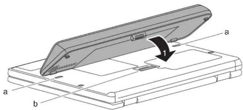
▶ First, locatethebatteryinthetwoslots(a).
▶ Foldthebatterydownintothebatteryconnectorinthedirectionofthe arrow(1)untilillocksintoplace.
natural_image
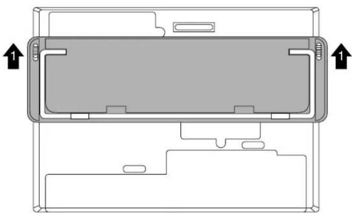
Diagram of a device casing with internal components and directional arrows indicating movement (no text or symbols)▶ Unfoldth etiltingdevice(1)onthebattery,ifpresent.
Removingthebattery
▶ Switchoffyournotebookanddisconnectthepowerplugfromthemainssocket.
▶ ClosetheLCDscreen.
▶ Disconnectallcablesconnectedtothenotebook.
▶ Turn your notebook over and place it on a stable, flat and clean surface. If necessary, lay a non-slip cloth on this surface to prevent the notebook from being scratched.
▶ Foldinthetiltingdeviceonthebattery,ifpresent.
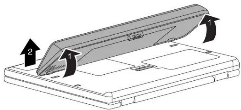
▶ Raise the battery at the rear corners (1) and lift out of the notebook from the front (2).
natural_image
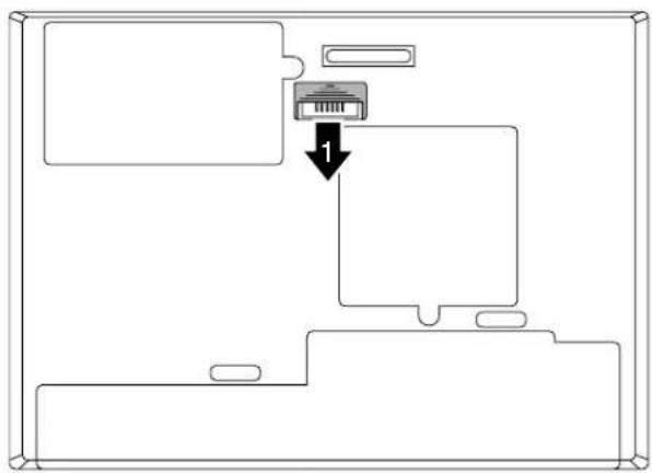
Pure diagram of a device interface with an internal component and directional arrow, no text or symbols present.▶ Slide the cover for the battery connector in the direction of the arrow (1).
SIMcard

FollowtheinstructionssuppliedbytheprovideroftheSIMcard.
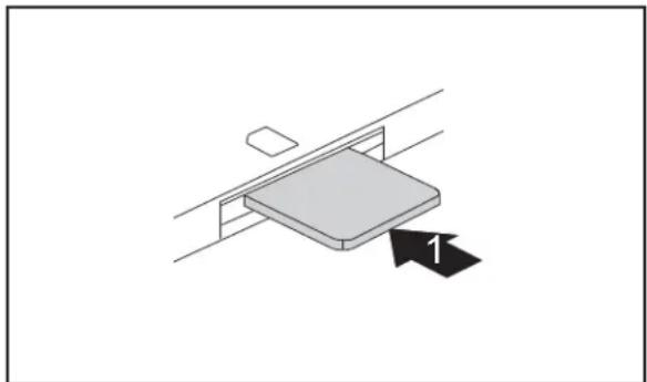
TheSIMcardslotislocatedinthebatterycompartment.Itcanonly beaccessedbytakingoutthebattery.
InsertingtheSIMcard
▶ Switch the notebook off and pull the power plug out of the mains socket.
▶ ClosetheLCDscreen.
▶ Disconnectallcablesconnectedtothenotebook.
▶ Turn your notebook over and place it on a stable, flat and clean surface. If necessary, lay an anti-slip cloth on thissurfacetoprevent then notebook from beings scratched.
Remove the battery (see Section "Removingthebattery", Page15).
natural_image
Isometric diagram of a mechanical or structural component with two parallel lines and a labeled arrow (no text or symbols)▶ Insert the SIM card into the slot so that thechipisfacingdownwardsandthe angledcornerisatthefrontleft,facing towardstheslot(1).Ensurethatyouhear theSIMcardclickintoplace.
▶ Reinstallthebattery( see" Insertingthebattery", Page15).
▶ Turn the notebook the right way up and place it on a flat surface.
▶ Reconnectthecablethat youdisconnectedpreviously.
RemovingtheSIMcard
▶ Switchthenotebookoffandpullthepowerplugoutofthemainssocket.
▶ ClosetheLCDscreensothatitlocksintoplace.
▶ Disconnectallcablesconnectedtothenotebook.
▶ Turn your notebook over and place it on a stable, flat and clean surface. If necessary, lay an anti-slip cloth on thissurfacetoprevent then notebook from beings scratched.
▶ Removethebattery(seeSection" Removingthebattery",Page15).
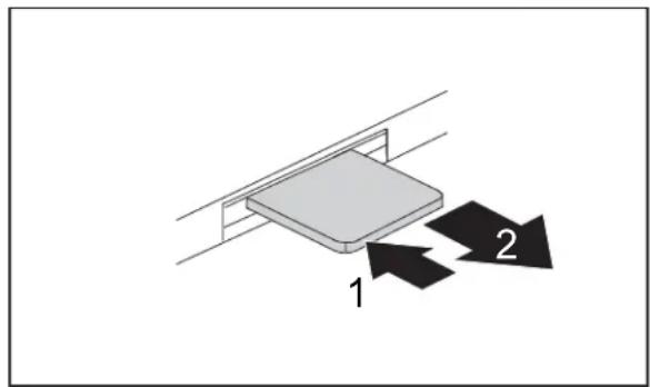
▶ Push the SIM card inwards slightly to ejectitfromtheslot(1).
▶ PulltheSIMcardoutoftheslotinthe directionofthearrow(2).
▶ Reinstallthebattery(see" Insertingthebattery",Page15).
▶ Turn the notebook the right way up and place it on a flat surface.
▶ Reconnectthecablesthatyoudisconnectedpreviously.
Radiocomponents: WirelessLAN/Bluetooth/UMTS

The installation of a wireless LAN modulen not approved by Fujitsu Siemens Computers GmbH, void the permits issued forth this device (see chapter "Technical data", Page 30).
Switchingtheradiocomponents onandoff
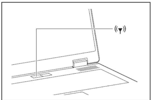
Start the WirelessSelector using the radio components EasyLaunch key or thekeycombination Fn + F1.
The WirelessSelector allows the radio components activated in BIOS Setup to beswitchedonandoffindividually.
natural_image
Line drawing of a laptop with a screen and antenna, no text or symbols present▶ PresstheEasyLaunchbuttontostart the WirelessSelector.
or
▶ Pressthekeycombination Fn + F1 tostarttheWirelessSelector.
→ Theradiocomponentindicatorwillbe illuminatedwhenoneormoreradio componentsisswitchedon.

If you switch off the radio components, the Bluetooth module, UMTS and wireless LANtransmissionunit(antenna) will alsobeswitched off.
Youcanenableor disabletheradiocomponentsindividually.
BIOSSetupallowsyoutospecifywhichradiocomponentscanbeswitchedonandoff usingtheEasyLaunchkeyorthekeycombination Fn + F1.Onlythosecomponents that have been activated in BIOS Setup can be switched on and off using the EasyLaunch key or the key combination Fn + F1. Conversely, components that are deactivated in BIOS setup cannot be controlled using the EasyLaunch key or the key combination.
You can also activate and deactivate the radio components individually in the BIOS Setup.
Payattentiontotheadditionalsafetynotesfordeviceswithradio componentsprovidedinthe"Safety"manual.
DetailsonusingWirelessLANcanbefoundintheonlinehelpsystem includedintheWirelessLANsoftware.
More detailed information on how to use Bluetooth can be found on the "Drivers & Utilities" CD/DVD.
You can obtain more information on UMTS from your service provider.
Removing and installing components during servicing

Only qualified technicians should repair your notebook. Unauthorised openingorincorrectrepairmaygreatlyendangertheuser(electricshock, fire risk) and will invalidate your warranty.
Youmayremoveandinstallthecomponentsdescribedinthischapteryourself afterconsultingtheHotline/HelpDesk.

If you remove and install components without consulting the Hotline/Help Desk, thent hewarranty of your notebook will be voided.
The illustrations shown below may differ from your actual device. They are merely intended to clarify the principles involved.
Notesoninstallingandremovingboards andcomponents
- Switchthenotebookoffandpullthepowerplugoutofthemainssocket.
- Removethebattery.
• Take care when you use the locking mechanisms on the battery and any other component.
• Never use sharp objects such as screwdrivers, scissors or knives as leverage to remove covers.

Boards with electrostatic sensitive devices (ESD) are marked with the label shown.
When handling boards fitted with ESDs, you must always observe the following points:
- You must always discharge static build up (e.g. by touching a grounded object) beforeworking.
• The equipment and tools you use must be free of static charges. - Remove the power plug from the mains supply before inserting or removing boardscontainingESDs.
• Always hold boards with ESDs by their edges. - Never touch pins or conductors on boards fitted with ESDs.
Harddisk
Theharddiskisthemostimportantstoragemediumofyournotebook. Youcanworkconsiderably faster and more efficiently if you copy applications and files from CDs to your hard disk.
Whentheharddiskisaccessed, theharddiskindicatorlightsupinthestatusindicatorpanel.
Removingtheharddisk
▶ Switch the notebook off and pull the power plug out of the mains socket.
▶ ClosetheLCDscreen.
▶ Disconnectallcablesconnectedtothenotebook.
▶ Turn your notebook over and place it on a stable, sturdy, flat surface. If necessary, lay an anti-slip cloth on this surface to prevent the notebook from being scratched.
▶ Removethebattery(see" Removingthebattery",Page15).
natural_image
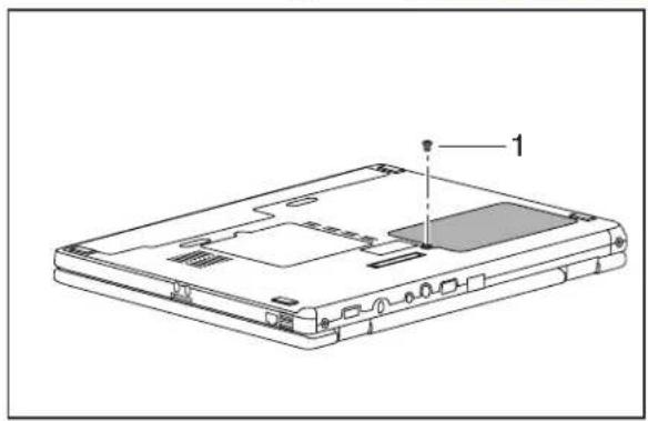
Line drawing of a laptop chassis showing front panel, rear panel, and internal components (no text or symbols)▶ Removethescrew(1).
▶ Liftofftheharddiskcover.
natural_image
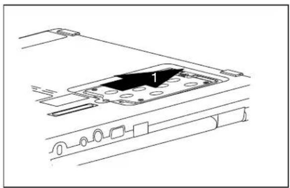
Technical line drawing of a device rear panel with a highlighted component (no text or symbols)▶ Usethepullingaidtopulltheharddiskout ofthebayinthedirectionofthearrow(1).
Installingtheharddisk
natural_image
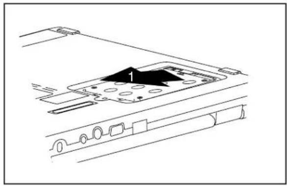
Technical line drawing of a device interior with labeled component '1' (no text or symbols beyond label)▶ Inserttheharddiskintothehard diskcompartmentinthedirection of thearrow(1).
natural_image
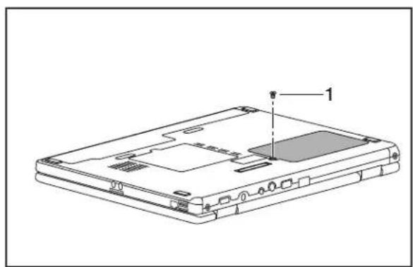
Line drawing of a laptop chassis showing front panel, rear panel, and internal components (no text or symbols)- Placetheharddiskcove rovertheopening. - Tightenthescrew(1).
▶ Installthebatteryagain(see" Insertingthebattery", Page15).
▶ Turn the notebook the right way up and place it on a flat surface.
▶ Reconnectthecablesthatyoudisconnectedpreviously.
Removing and installing memory modules

Yournotebooksupportsdual-channelDDR2technology.
The dual-channel DDR2 technology can only be used with two identical memory modules. Whentwodifferentmemorymodules are installed, only "single-channel" mode is supported. This reduces the performance of your notebook.
With a memory configuration of 4 GBytes, the visible and usable main memory may be reduced to 3GBytes (depending on the operating system).
If you are asked by the Hotline/Help Desktop to move and install them memory modules yourself, proceeds as follows:

Pay attention to the relevant safety notes provided in the "Important notes" chapter.
Thenotebookmustbeswitchedoffwheninstalling/removingthememory modules,itmustnotbeinSuspendmode.
Onlyuseapprovedmemoryexpansionmodulesinyournotebook (seeSection" Technicaldata",Page30).
Neveruseforcewheninstallingorremovingmemorymodules.
Make sure that foreign objects do not fall into the memory expansion compartment.

Individualcomponents(e.g.the processorheatsink)canbecomeveryhot duringoperation.Therefore, werecommendthatyouwaitonehourafter switchingoffthenotebookbef oreremovingorinstallingthememorymodules. Otherwise,thereisariskofsu fferingburns!
Assome non-ESDsafe components are exposed, please observe the section "Notes oninstallingandremovingboa rdsandcomponents", Page23.
▶ Switch your notebook off and unplug the mains adapter from the mains outlet.
▶ ClosetheLCDscreen.
▶ Disconnectallcablesconnectedtothenotebook.
▶ Turn your notebook over and place it on a stable, flat and clean surface. If necessary, lay an anti-slip cloth th on this surfacetoprevent then notebook from beings scratched.
▶ Removethebattery(see" Removingthebattery",Page15).
Removingthecover
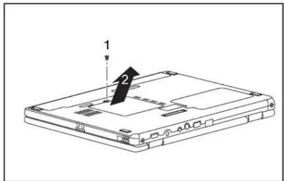
▶ Removethescrew(1).
▶ Pullthecoveroffthenotebook(2).
Removingmemorymodules
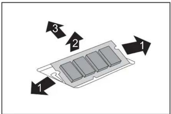
▶ Carefullypushthetw omounting clipsoutwards(1).
→ Thememorymodulesnapsupwards(2).
▶ Pullthememorymoduleou to fits slot inthedirectionofthear row(3).
Installingamemorymodule
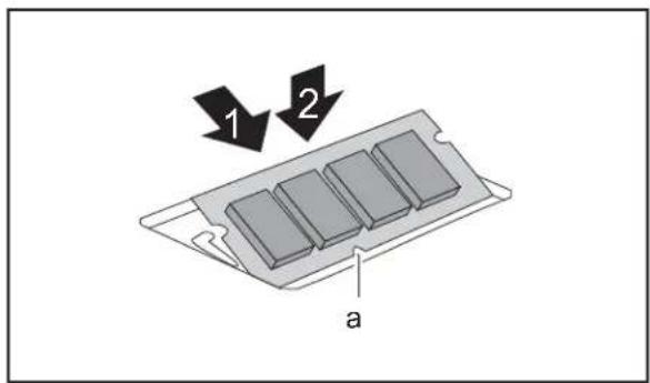
▶ Insertthememorymodulewiththecontacts andtherecess(a)facingtheslot(1).
▶ Carefullypushthememorymodule downwardsuntilyoufeelitclick intoplace(2).
Attachingthecover
natural_image
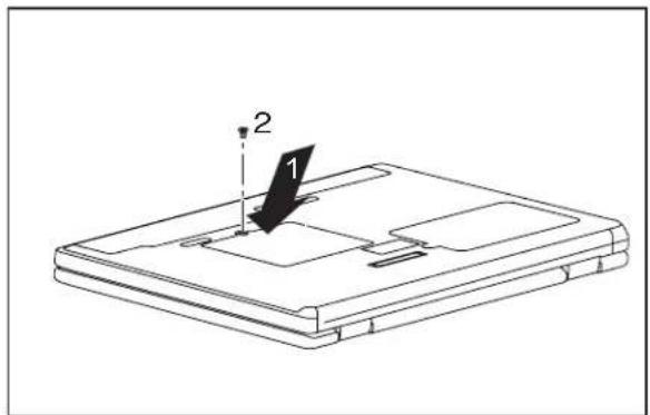
Line drawing of a device with a labeled component (1) and numbered point (2), no text or symbols present.▶ Placethecoverinthecorrect mountingposition(1).
▶ Fastenthecoverwiththescrew(2).
▶ Reinstallthebattery(see" Insertingthebattery",Page15).
▶ Turnthenotebooktheri ghtwayupandplaceitonaflatsurface.
▶ Reconnectthecablesthatyoudisconnectedpreviously.
Removing and installing the opt icaldrive
If you are asked by the Hotline/Help Desktop to remove and install the optical drive yourself, proceeds as follows:
Removingtheopticaldrive
▶ Switchoffyournotebookanddisconnectthepowerplugfromthemainssocket.
▶ ClosetheLCDscreen.
▶ Disconnectallcablesconnectedtothenotebook.
▶ Turnyournotebookoverandplaceitonaflatsurface.
▶ Removethebattery(seeChapter" Removingthebattery",Page15).
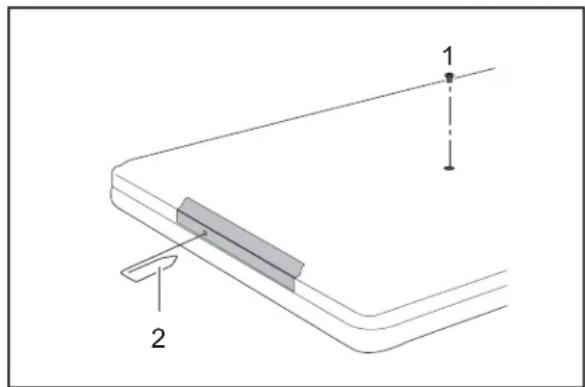
▶ Removethescrew(1).
▶ Pressametalpinorwire(e.g.paperclip) firmlyintotheopening(2).
→ Thedrivetraywillbeejected.Youcannow pulloutthedrivetraycompletely.
▶ Hold the drive tray firmly on both sides in the centre, and carefully pull theopticaldriveoutofthenotebook.
▶ Pushinthedrivetrayuntilyoufeelitlockintoplace.
Installingtheopticaldrive
natural_image
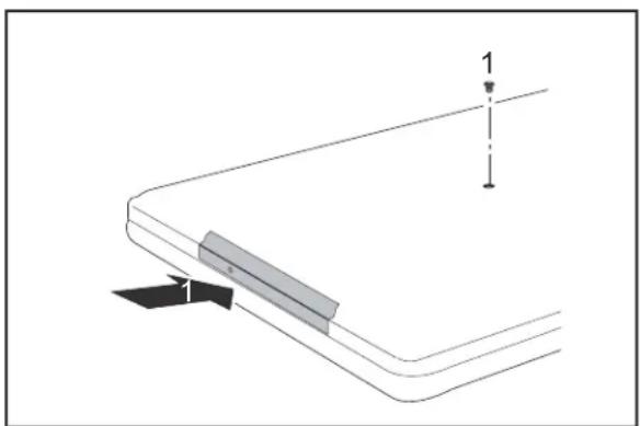
Pure technical diagram of a mechanical component with no text, numbers, or symbols▶ Slidethedriveintothenotebookinthe directionofthearrow(1).
▶ Tightenthescrew(2).
▶ Reinstallthebattery(see" Insertingthebattery",Page15).
▶ Turn the notebook the right way up and place it on a flat surface.
▶ Reconnectthecablesthatyoudisconnectedpreviously.
Technicaldata
Notebook
| Environmentalconditions | |
| Environmentalclass3K2 | |
| Temperature | |
| Operating(3K2)5°C–35°C | |
| Transportation(2K2)-15°C–60°C | |
| Dimensions | |
| WidthxDepthxHeight(front/back)•ESPRIMOMobile | U9200:300mmx223mmx37.5mm•ESPRIMOMobileM9400:335mmx245mmx38mm•ESPRIMOMobileD9500:360mmx260mmx37.5mm |
| Weight (depending on configuration) | • ESPRIMO Mobile U9200: Approx. 1.9 kg•ESPRIMOMobileM9400:Approx.2.2 kg•ESPRIMOMobile D9500:Approx.2.5kg |

The data sheet for this notebook contains further technical data. The data sheet can be found on your notebook or the Internet at "www.fujitsu-siemens.com" or on the "Drivers & Utilities" CD/DVD.
Battery
| Mainbattery | Secondbattery/travelbattery | |
| Ratedvoltage | 11.1V | 11.1V |
| Ratedcapacity | 5200mAh | 3800mAh |

The operating time depends on the device equipment, the active applications and the energy saving settings.
Mains adapter
| Electricaldata | |
| Ratedvoltage | 20V |
| Max. ratedcurrent | 4.5A |
Anadditionalmainsadapterandpowercablecanbeorderedatanytime.
Index
A
Activateenergysavingmode13
Alt+Tab13
B
Backtab13
Battery5
importantnotes15
inserting15
removing15–16,18
Batterychargingindicator11
Batteryindicator seebatteryindicator11
Batteryreleaselatch5
Batterysymbol seebatteryindicator11
Bluetooth22
switchingoff12,22
switchingon12,22
Board23
C
Camera5
switchingoff12
switchingon12
CapsLock
indicator11
CapsLockindicator11
Components
installing/removing23
Ctrl+Alt+Del13
D
DCjack(DCIN)5
Driveindicator11
E
EasyLaunchkey5
ESD23
ExpressCardslot5
F
Fn+F112
Fn+F1013
Fn+F1213
Fn+F312
Fn+F412
Fn+F512
Fn+F612
Fn+F712
Fn+F812
Fn+F913
H
Harddisk5
removing24,29
Headphoneport5
|
Indicator
Drive11
K
KensingtonLock5
L
LANport5
Loudspeaker
switchingON/OFF12
M
Mainmemory26
Memorycardslot5
Memoryexpansion26
installing27
removing27
Memorymodule
installing27
removing27
Memoryupgrade26
Microphone5
Microphoneport5
Modemport5
Monitorport5
N
Notes
battery15
boards23
travelbattery16
NumLock
indicator11
NumLockindicator11
0
ON/OFFswitch5
Opticaldrive5
R
Radiocomponentsindicator11
S
S-Videooutsocket5
Screenbrightness decrease12 increase13
Scroll indicator11
ScrollLockindicator11
ScrollLock: indicator11
Servicing23
Shift+Tab13
Sleepmode activating13
Statusindicators5,10
Systemexpansion memoryexpansion26
T
Technicaldata battery30 Notebook
Technicaldataforthe
mainsadapter30
Toggleoutputscreen13
Touchpad5 switchingoff12 switchingon12
Touchpadbuttons5
Travelbattery importantnotes16
U
UMTS22 switchingoff22 switchingon22
USBport5
V
Volume decrease12 increase12
W
Warmreboot13
WirelessLAN22 switchingoff22 switchingon22
WLAN switchingoff12 switchingon12
- ESPRIMOMobileSeries
- Arethere...
- YourESPRIMOMobile1
- Contents
- YourESPRIMOMobile 1
- Importantnotes 3
- Portsandoperatingelements 4
- Removing and installing components during servicing 23
- Technical data 30
- Index 31
- YourESPRIMOMobile
- Importantnotes
- Portsandoperatingelements
- ESPRIMOMobileU9200
- Switchingonthenotebook
- WindowsXP
- WindowsVista
- SwitchingofftheNotebook
- Statusindicators
- Power-onindicator
- Batterychargingindicator
- Driveindicator
- CapsLockindicator
- ScrollLockindicator
- NumLockindicator
- Radiocomponentsindicator
- Keycombinations
- Switchingtheradiocomponentson/off
- SwitchloudspeakersON/OFF
- Decrease volume
- Increasesvolume
- SwitchtouchpadON/OFF
- SwitchcameraON/OFF(dependingonyourdevice)
- Decreasescreen brightness
- Increasescreenbrightness
- Toggleoutputscreen
- Sleepmode
- Switchingbetweenopenapplications
- Performwarmreboot
- Backtab
- Camera(dependingonnotebookmodel)
- Removing and installing the battery
- Removingthebattery
- Insertingthebattery
- Removing/fittingthesecondbattery/travel battery(optional)
- Installingthebattery
- SIMcard
- InsertingtheSIMcard
- RemovingtheSIMcard
- Radiocomponents: WirelessLAN/Bluetooth/UMTS
- Switchingtheradiocomponents onandoff
- or
- Removing and installing components during servicing
- Notesoninstallingandremovingboards andcomponents
- Harddisk
- Removingtheharddisk
- Installingtheharddisk
- Removing and installing memory modules
- Removingthecover
- Removingmemorymodules
- Installingamemorymodule
- Attachingthecover
- Removing and installing the opt icaldrive
- Removingtheopticaldrive
- Installingtheopticaldrive
- Technicaldata
- Notebook
- Battery
- Mains adapter
- Index
- A
- B
- C
- D
- E
- F
- H
- |
- K
- L
- M
- N
- 0
- R
- S
- T
- U
- V
- W
Brand : FUJITSU SIEMENS
Model : ESPRIMO Mobile U9200
Category : Laptop