
Flex 2-15D - Laptop LENOVO - Free user manual and instructions
Find the device manual for free Flex 2-15D LENOVO in PDF.


| Product Type | Laptop |
| Model | Lenovo Flex 2-15D |
| Processor | AMD APU (A6-6400, E1-6010, A8-6410, or A6-6310) |
| Graphic Chipset | AMD Sun Pro / AMD Integrated |
| Display | 15.6-inch HD (1366x768) or FHD (1920x1080); 16:9 aspect ratio |
| Memory | DDR3L-1333/1600 MHz; up to 16 GB (2 SODIMM slots) |
| Hard Disk Drive | 2.5-inch, 7.0mm height; SATA 3.0 interface |
| Optical Drive | 9.0mm RAMBO (DVD±RW); not present on all models |
| SSD (optional) | NGFF 16GB or SATA 128GB/256GB |
| I/O Ports | 1x HDMI, 1x Combo audio jack, 2x USB 3.0, 1x USB 2.0, RJ-45, Memory card slot, Kensington slot |
| Wireless LAN | Intel Wifi 2x2 BGN + BT 4.0 or Intel Wifi A/C BGN + BT 4.0 |
| Bluetooth | Integrated with WLAN (not discrete) |
| Camera | HD (640x480) or 1.0MP with microphone |
| Battery | Lithium-ion (removable) |
| AC Adapter | 45W or 65W (3-pin) |
| Pre-installed OS | Windows 8 (64-bit) or Linpus |
| Keyboard | New keyboard with optional backlight; numeric keypad on 15-inch models |
| Touchpad | One piece touch pad with buttons |
| Security | Power-on, hard-disk, and supervisor passwords; Kensington lock slot |
| Power Management | Sleep (standby), hibernation, screen blank, adjustable brightness via hotkeys |
| Serviceability | FRU replacement with detailed instructions; nylon-coated screws; torque specifications |
Frequently Asked Questions - Flex 2-15D LENOVO
User questions about Flex 2-15D LENOVO
0 question about this device. Answer the ones you know or ask your own.
Ask a new question about this device
Download the instructions for your Laptop in PDF format for free! Find your manual Flex 2-15D - LENOVO and take your electronic device back in hand. On this page are published all the documents necessary for the use of your device. Flex 2-15D by LENOVO.
USER MANUAL Flex 2-15D LENOVO
Before using this information and the product it supports, be sure to read the general information under “Notices” on page 104.
First Edition (March 2014)
© Copyright Lenovo 2014. All rights reserved.
LENOVO products, data, computer software, and services have been developed exclusively at private expense and are sold to governmental entities as commercial items as defined by 48 C.F.R. 2.101 with limited and restricted rights to use, reproduction and disclosure.
LIMITED AND RESTRICTED RIGHTS NOTICE: If products, data, computer software, or services are delivered pursuant a General Services Administration "GSA" contract, use, reproduction, or disclosure is subject to restrictions set forth in Contract No. GS-35F-05925.
© 2014 Lenovo
Contents
About this manual......iv
Safety information....1
General safety 2
Electrical safety.... 3
Safety inspection guide 5
Handling devices that are sensitive to electrostatic discharge....6
Grounding requirements 6
Safety notices: multilingual translations...... 7
Laser compliance statement.... 14
Important service information ....16
Strategy for replacing FRUs...... 16
Strategy for replacing a hard disk drive .... 17
Important notice for replacing a system board .... 17
Important information about replacing RoHS compliant FRUs 18
General checkout ....19
What to do first.... 20
Power system checkout.... 21
Checking the AC adapter.... 21
Checking operational charging.... 22
Checking the battery pack 22
Related service information ....23
Restoring the factory contents by using
Recovery Disc Set.... 23
Start Recovery Disc (one disc).... 23
Operating System Recovery Disc (one or more discs) 23
Applications and Drivers Recovery Disc (one or more discs).... 23
Supplemental Recovery Disc.... 23
Passwords.... 24
Power-on password.... 24
Hard-disk password.... 24
Supervisor password 24
Power management 25
Screen blank state.... 25
Putting the computer to sleep or shutting it down 25
Lenovo Flex 2-14/Flex 2-14D/Flex 2-15/Flex
2-15D 27
Specifications 27
Status indicators 29
Hotkeys.... 31
FRU replacement notices....32
Screw notices....32
Removing and replacing an FRU ....33
1010 Keyboard....34
1020 Optical drive....36
1030 Hard disk drive(HDD)/Memory/Mini PCI Express Card slot compartment cover 37
1040 Battery pack....39
1050 Hard disk drive....40
1060 DIMM....42
1070 PCI Express Mini Card for wireless LAN/WAN 43
1080 Fan assembly and Heat Sink assembly....45
1090 System board....49
1100 LCD unit....53
1110 Speakers, base cover, IO board, DC-IN, power board and ODD transfer board .....56
1120 LCD front bezel....64
1130 LCD panel, LCD cable and hinges ... 66
1140 Integrated camera....68
1150 Antenna assembly and LCD cover...69
Locations 70
Front view....70
Bottom and Left-side view ....72
Right-side view 73
Parts list....74
Overall....75
LCD FRUs....85
Keyboard....88
AC adapters....100
Screws....100
Power cords....101
Notices 104
Trademarks....105
About this manual
This manual contains service and reference information for the following Lenovo product:
Lenovo Flex 2-14/Flex 2-14D/Flex 2-15/Flex 2-15D
Use this manual to troubleshoot problems.
The manual is divided into the following sections:
- The common sections provide general information, guidelines, and safety information required for servicing computers.
- The product-specific section includes service, reference, and product-specific parts information.
Important:
This manual is intended only for trained servicers who are familiar with Lenovo products. Use this manual to troubleshoot problems effectively. Before servicing a Lenovo product, make sure to read all the information under “Safety information” on page 1 and “Important service information” on page 16.
Safety information
This chapter presents the following safety information that you need to get familiar with before you service a Lenovo computer:
- "General safety" on page 2
• "Electrical safety" on page 3 - "Safety inspection guide" on page 5
- "Handling devices that are sensitive to electrostatic discharge" on page 6
- "Grounding requirements" on page 6
- "Safety notices: multilingual translations" on page 7
- "Laser compliance statement" on page 14
General safety
Follow these rules below to ensure general safety:
- Observe a good housekeeping in the area where the machines are put during and after the maintenance.
-
When lifting any heavy object:
-
Make sure that you can stand safely without slipping.
- Distribute the weight of the object equally between your feet.
- Use a slow lifting force. Never move suddenly or twist when you attempt to lift it.
-
Lift it by standing or pushing up with your leg muscles; this action could avoid the strain from the muscles in your back. Do not attempt to lift any object that weighs more than 16 kg (35 lb) or that you think is too heavy for you.
-
Do not perform any action that causes hazards to the customer, or that makes the machine unsafe.
- Before you start the machine, make sure that other service representatives and the customer are not in a hazardous position.
- Please remove covers and other parts in a safe place, away from all personnel, while you are servicing the machine.
- Keep your toolcase away from walk areas so that other people will not trip it over.
- Do not wear loose clothing that can be trapped in the moving parts of the machine. Make sure that your sleeves are fastened or rolled up above your elbows. If your hair is long, fasten it.
- Insert the ends of your necktie or scarf inside clothing or fasten it with the nonconductive clip, about 8 centimeters (3 inches) from the end.
- Do not wear jewelry, chains, metal-frame eyeglasses, or metal fasteners for your clothing.
Attention: Metal objects are good electrical conductors.
- Wear safety glasses when you are hammering, drilling, soldering, cutting wire, attaching springs, using solvents, or working in any other conditions that may be hazardous to your eyes.
- After service, reinstall all safety shields, guards, labels, and ground wires. Replace any safety device that is worn or defective.
- Reinstall all covers correctly before returning the machine to the customer.
- Fan louvers on the machine help to prevent the overheating of internal components. Do not obstruct fan louvers or cover them with labels or stickers.
Electrical safety
Observe the following rules when working on electrical equipments.
Important:
Use only approved tools and test equipments. Some hand tools have handles covered with a soft material that does not insulate you when working with live electrical currents.
Many customers have rubber floor mats near their machines that contain small conductive fibers to decrease electrostatic discharges. Do not use such kind of mat to protect yourself from electrical shock.
- Find the room emergency power-off (EPO) switch, disconnecting switch, or electrical outlet. If an electrical accident occurs, you can then operate the switch or unplug the power cord quickly.
- Do not work alone under hazardous conditions or near the equipment that has hazardous voltages.
-
Disconnect all power before:
-
Performing a mechanical inspection
- Working near power supplies
-
Removing or installing main units
-
Before you start to work on the machine, unplug the power cord. If you cannot unplug it, ask the customer to power-off the wall box that supplies power to the machine, and to lock the wall box in the off position.
- If you need to work on a machine that has exposed electrical circuits, observe the following precautions:
- Ensure that another person, familiar with the power-off controls, is near you.
Attention: Another person must be there to switch off the power, if necessary.
- Use only one hand when working with powered-on electrical equipment; keep the other hand in your pocket or behind your back.
Attention: An electrical shock can occur only when there is a complete circuit. By observing the above rule, you may prevent a current from passing through your body.
- When using testers, set the controls correctly and use the approved probe leads and accessories for that tester.
- Stand on suitable rubber mats (obtained locally, if necessary) to insulate you from grounds such as metal floor strips and machine frames.
Observe the special safety precautions when you work with very high voltages; instructions for these precautions are in the safety sections of maintenance information. Be extremely careful when you measure the high voltages.
- Regularly inspect and maintain your electrical hand tools for safe operational condition.
- Do not use worn or broken tools and testers.
- Never assume that power has been disconnected from a circuit. First, check it to make sure that it has been powered off.

Lenovo Flex 2-14/Flex 2-14D/Flex 2-15/Flex 2-15D Hardware Maintenance Manual
- Always look carefully for possible hazards in your work area. Examples of these hazards are moist floors, nongrounded power extension cables, power surges, and missing safety grounds.
- Do not touch live electrical circuits with the reflective surface of a plastic dental mirror. The surface is conductive; such touching can cause personal injury and machine damage.
- Do not service the following parts with the power on when they are removed from their normal operating places in a machine:
– Power supply units
- P u m p s
- Blowers and fans
- Motor generators
and similar units. (This practice ensures correct grounding of the units.)
- If an electrical accident occurs:
- Use caution: do not become a victim yourself.
- Switch off the power.
- Send the victim to get medical aid.
Safety inspection guide
The purpose of this inspection guide is to assist you in identifying potential unsafe conditions. As each machine was designed and built, required safety items were installed to protect users and service personnel from injury. This guide addresses only those items. You should use good judgment to identify potential safety hazards due to attachment of non-Lenovo features or options not covered by this inspection guide.
If any unsafe conditions are present, you must determine how serious the apparent hazard could be and whether you can continue without first correcting the problem.
Consider these conditions and the safety hazards they present:
- Electrical hazards, especially primary power (primary voltage on the frame can cause serious or fatal electrical shock)
- Explosive hazards, such as a damaged CRT face or a bulging capacitor
- Mechanical hazards, such as loose or missing hardware
To determine whether there are any potential unsafe conditions, use the following checklist at the beginning of every service task. Begin the checks with the power off, and the power cord disconnected.
Checklist:
- Check exterior covers for damage (loose, broken, or sharp edges).
- Turn off the computer. Disconnect the power cord.
- Check the power cord for:
a. A third-wire ground connector in good condition. Use a meter to measure third-wire ground continuity for 0.1 ohm or less between the external ground pin and the frame ground.
b. The power cord should be the type specified in the parts list.
c. Insulation must not be frayed or worn.
- Check for cracked or bulging batteries.
- Remove the cover.
- Check for any obvious non-Lenovo alterations. Use good judgment as to the safety of any non-Lenovo alterations.
- Check inside the unit for any obvious unsafe conditions, such as metal filings, contamination, water or other liquids, or signs of fire or smoke damage.
- Check for worn, frayed, or pinched cables.
- Check that the power-supply cover fasteners (screws or rivets) have not been removed or tampered with.
Handling devices that are sensitive to electrostatic discharge
Any computer part containing transistors or integrated circuits (ICs) should be considered sensitive to electrostatic discharge (ESD). ESD damage can occur when there is a difference in charge between objects. Protect against ESD damage by equalizing the charge so that the machine, the part, the work mat, and the person handling the part are all at the same charge.
Notes:
- Use product-specific ESD procedures when they exceed the requirements noted here.
- Make sure that the ESD protective devices you use have been certified (ISO 9000) as fully effective.
When handling ESD-sensitive parts:
- Keep the parts in protective packages until they are inserted into the product.
- Avoid contact with other people.
- Wear a grounded wrist strap against your skin to eliminate static on your body.
- Prevent the part from touching your clothing. Most clothing is insulative and retains a charge even when you are wearing a wrist strap.
- Use the black side of a grounded work mat to provide a static-free work surface. The mat is especially useful when handling ESD-sensitive devices.
- Select a grounding system, such as those listed below, to provide protection that meets the specific service requirement.
Notes:
The use of a grounding system to guard against ESD damage is desirable but not necessary.
- Attach the ESD ground clip to any frame ground, ground braid, or green-wire ground.
- When working on a double-insulated or battery-operated system, use an ESD common ground or reference point. You can use coax or connector-outside shells on these systems.
- Use the round ground prong of the ac plug on ac-operated computers.
Grounding requirements
Electrical grounding of the computer is required for operator safety and correct system function. Proper grounding of the electrical outlet can be verified by a certified electrician.
Safety notices: multilingual translations
The safety notices in this section are provided in English, French, German, Hebrew, Italian, Japanese, and Spanish.
Safety notice 1
Before the computer is powered on after FRU replacement, make sure all screws, springs, and other small parts are in place and are not left loose inside the computer. Verify this by shaking the computer and listening for rattling sounds. Metallic parts or metal flakes can cause electrical shorts.
Some standby batteries contain a small amount of nickel and cadmium. Do not disassemble a standby battery, recharge it, throw it into fire or water, or short-circuit it. Dispose of the battery as required by local ordinances or regulations. Use only the battery in the appropriate parts listing. Use of an incorrect battery can result in ignition or explosion of the battery.
The battery pack contains small amounts of nickel. Do not disassemble it, throw it into fire or water, or short-circuit it. Dispose of the battery pack as required by local ordinances or regulations. Use only the battery in the appropriate parts listing when replacing the battery pack. Use of an incorrect battery can result in ignition or explosion of the battery.
The lithium battery can cause a fire, an explosion, or a severe burn. Do not recharge it, remove its polarized connector, disassemble it, heat it above 100^ C ( 212^ F), incinerate it, or expose its cell contents to water. Dispose of the battery as required by local ordinances or regulations. Use only the battery in the appropriate parts listing. Use of an incorrect battery can result in ignition or explosion of the battery.
If the LCD breaks and the fluid from inside the LCD gets into your eyes or on your hands, immediately wash the affected areas with water at least for 15 minutes. Seek medical care if any symptoms caused by the fluid are present after washing.
To avoid shock, do not remove the plastic cover that protects the lower part of the inverter card.
Though the main batteries have low voltage, a shorted or grounded battery can produce enough current to burn personnel or combustible materials.
Before removing any FRU, turn off the computer, unplug all power cords from electrical outlets, remove the battery pack, and then disconnect any interconnecting cables.
Laser compliance statement
Some models of Lenovo computer are equipped from the factory with an optical storage device such as a CD-ROM drive or a DVD-ROM drive. Such devices are also sold separately as options. If one of these drives is installed, it is certified in the U.S. to conform to the requirements of the Department of Health and Human Services 21 Code of Federal Regulations (DHHS 21 CFR) Subchapter J for Class 1 laser products. Elsewhere, the drive is certified to conform to the requirements of the International Electrotechnical Commission (IEC) 825 and CENELEC EN 60 825 for Class 1 laser products.
If a CD-ROM drive, a DVD-ROM drive, or another laser device is installed, note the following:
CAUTION
Opening the CD-ROM drive, the DVD-ROM drive, or any other optical storage device could result in exposure to hazardous laser radiation. There are no serviceable parts inside those drives. Do not open.
A CD-ROM drive, a DVD-ROM drive, or any other storage device installed may contain an embedded Class 3A or Class 3B laser diode. Note the following:
DANGER
Emits visible and invisible laser radiation when open. Do not stare into the beam, do not view directly with optical instruments, and avoid direct exposure to the beam.
Important service information
This chapter presents the following important service information:
- "Strategy for replacing FRUs" on page 16
- "Strategy for replacing a hard disk drive" on page 17
- "Important notice for replacing a system board" on page 17
- "Important information about replacing RoHS compliant FRUs" on page 18
Important:
BIOS and device driver fixes are customer-installable. The BIOS and device drivers are posted on the customer support site: http://support.lenovo.com.
Strategy for replacing FRUs
Before replacing parts:
Make sure that all software fixes, drivers, and BIOS downloads are installed before replacing any FRUs listed in this manual.
After a system board is replaced, ensure that the latest BIOS is loaded to the system board before completing the service action.
To download software fixes, drivers, and BIOS, follow the steps below:
- Go to http://support.lenovo.com.
- Enter the serial number or select a product or use Lenovo smart downloading.
- Select the BIOS/Driver/Applications and download.
- Follow the directions on the screen and install the necessary software.
Use the following strategy to prevent unnecessary expense for replacing and servicing FRUs:
- If you are instructed to replace an FRU, but the replacement does not solve the problem, reinstall the original FRU before you continue.
- Some computers have both a processor board and a system board. If you are instructed to replace either of them, and replacing one of them does not solve the problem, reinstall that board, and then replace the other one.
- If an adapter or a device consists of more than one FRU, any of the FRUs may be the cause of the error. Before replacing the adapter or device, remove the FRUs one by one to see if the symptoms change. Replace only the FRU that changed the symptoms.
Attention: The setup configuration on the computer you are servicing may have been customized. Running Automatic Configuration may alter the settings. Note the current configuration settings (using the View Configuration option); then, when service has been completed, verify that those settings remain in effect.
Strategy for replacing a hard disk drive
Always try to run a low-level format before replacing a hard disk drive. This will cause all customer data on the hard disk to be lost. Make sure that the customer has a current backup of the data before performing this action.
Attention: The drive startup sequence in the computer you are servicing may have been changed. Be extremely careful during write operations such as copying, saving, or formatting. If you select an incorrect drive, data or programs can be overwritten.
Important notice for replacing a system board
Some components mounted on a system board are very sensitive. Improper handling can cause damage to those components, and may cause a system malfunction.
Attention: When handling a system board:
- Do not drop the system board or apply any excessive force to it.
- Avoid rough handling of any kind.
- Avoid bending the system board and hard pushing to prevent cracking at each BGA (Ball Grid Array) chipset.
Important information about replacing RoHS compliant FRUs
RoHS, The Restriction of Hazardous Substances in Electrical and Electronic Equipment Directive (2002/95/EC) is a European Union legal requirement affecting the global electronics industry. RoHS requirements must be implemented on Lenovo products placed on the market after June 2006. Products on the market before June 2006 are not required to have RoHS compliant parts. If the original FRU parts are non-compliant, replacement parts can also be non-compliant. In all cases if the original FRU parts are RoHS compliant, the replacement part must also be RoHS compliant.
Note: RoHS and non-RoHS FRU part numbers with the same fit and function are identified with unique FRU part numbers.
Lenovo plans to transit to RoHS compliance well before the implementation date and expects its suppliers to be ready to support Lenovo's requirements and schedule in the EU. Products sold in 2005 and 2006 will contain some RoHS compliant FRUs. The following statement pertains to these products and any product Lenovo produces containing RoHS compliant FRUs.
RoHS compliant FRUs have unique FRU part numbers. Before or after the RoHS implementation date, failed RoHS compliant parts must always be replaced with RoHS compliant ones, so only the FRUs identified as compliant in the system HMM or direct substitutions for those FRUs may be used.
| Products marketed before June 2006 | Products marketed after June 2006 | ||
| Current or original part | Replacement FRU | Current or original part | Replacement FRU |
| Non-RoHS Can be | Non-RoHS | Must be RoHS Must be RoHS | |
| Non-RoHS Can be | RoHS | ||
| Non-RoHS Can sub to RoHS | |||
| RoHS Must be RoHS | |||
Note: A direct substitution is a part with a different FRU part number that is automatically shipped by the distribution center at the time of the order.
General checkout
This chapter presents the following information:
• "What to do first" on page 20
- "Power system checkout" on page 21
Before you go to the checkout, make sure to read the following important notes:
Important notes:
- Only certified trained personnel can service the computer.
- Before replacing any FRU, read the entire page on removing and replacing FRUs.
- When you replace FRUs, use new nylon-coated screws.
- Be extremely careful during such write operations as copying, saving, or formatting. Drives in the computer that you are servicing sequence might have been altered. If you select an incorrect drive, data or programs might be overwritten.
- Replace an FRU only with another FRU of the correct model. When you replace an FRU, make sure that the machine model and the FRU part number are correct by referring to the FRU parts list.
- An FRU should not be replaced just because of a single, unreproducible failure. Single failures can occur for a variety of reasons that have nothing to do with a hardware defect, such as cosmic radiation, electrostatic discharge, or software errors. Consider replacing an FRU only when a problem recurs. If you suspect that an FRU is defective, clear the error logs and run the test again. If the error does not recur, do not replace the FRU.
- Be careful not to replace a nondefective FRU.
What to do first
When you do return an FRU, you must include the following information in the parts exchange form or parts return form that you attach to it:
- Name and phone number of servicer
- Date of service
- Date on which the machine failed
- Date of purchase
- Procedure index and page number in which the failing FRU was detected
- Failing FRU name and part number
- Machine type, model number, and serial number
- Customer's name and address
Note for warranty: During the warranty period, the customer may be responsible for repair costs if the computer damage was caused by misuse, accident, modification, unsuitable physical or operating environment, or improper maintenance by the customer.
The following is a list of some common items that are not covered under warranty and some symptoms that might indicate that the system was subjected to stress beyond normal use.
Before checking problems with the computer, determine whether the damage is covered under the warranty by referring to the following list:
The following are not covered under warranty:
- LCD panel cracked from the application of excessive force or from being dropped
- Scratched (cosmetic) parts
- Distortion, deformation, or discoloration of the cosmetic parts
- Plastic parts, latches, pins, or connectors that have been cracked or broken by excessive force
- Damage caused by liquid spilled into the system
- Damage caused by the improper insertion of a PC Card or the installation of an incompatible card
- Improper disk insertion or use of an optical drive
- Diskette drive damage caused by pressure on the diskette drive cover, foreign material in the drive, or the insertion of a diskette with multiple labels
- Damaged or bent diskette eject button
- Fuses blown by attachment of a nonsupported device
- Forgotten computer password (making the computer unusable)
- Sticky keys caused by spilling a liquid onto the keyboard
- Use of an incorrect AC adapter on laptop products
The following symptoms might indicate damage caused by nonwarranted activities:
- Missing parts might be a symptom of unauthorized service or modification.
- If the spindle of a hard disk drive becomes noisy, it may have been subjected to excessive force, or dropped.
Power system checkout
To verify a symptom, follow the steps below:
- Turn off the computer.
- Remove the battery pack.
- Connect the AC adapter.
- Make sure that power is supplied when you turn on the computer.
- Turn off the computer.
- Disconnect the AC adapter and install the charged battery pack.
- Make sure that the battery pack supplies power when you turn on the computer.
If you suspect a power problem, see the appropriate one of the following power supply checkouts:
- "Checking the AC adapter" on page 21
- "Checking operational charging" on page 22
- "Checking the battery pack" on page 22
Checking the AC adapter
You are here because the computer fails only when the AC adapter is used.
- If the power-on indicator does not turn on, check the power cord of the AC adapter for correct continuity and installation.
- If the computer does not charge during operation, go to "Checking operational charging".
To check the AC adapter, follow the steps below:
- Unplug the AC adapter cable from the computer.
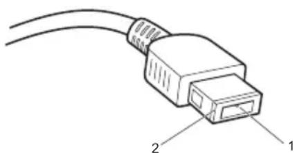
- Measure the output voltage at the plug of the AC adapter cable. See the following figure:
natural_image
Line drawing of an Ethernet cable with labeled ports 1 and 2 (no text or symbols beyond labels)| Pin | Voltage (V DC) |
| 1 | +20 |
| 2 | 0 |
Note: Output voltage for the AC adapter pin No. 2 may differ from the one you are servicing.
- If the voltage is not correct, replace the AC adapter.
-
If the voltage is acceptable, do the following:
-
Replace the system board.
- If the problem persists, go to "Lenovo Flex 2-14/Flex 2-14D/Flex 2-15/Flex 2-15D" on page 27.
Note: Noise from the AC adapter does not always indicate a defect.
Checking operational charging
To check whether the battery charges properly during operation, use a discharged battery pack or a battery pack that has less than 50% of the total power remaining when installed in the computer.
Perform operational charging. If the battery status indicator or icon does not light on, remove the battery pack and let it return to room temperature. Reinstall the battery pack. If the charge indicator or icon is still off, replace the battery pack.
If the charge indicator still does not light on, replace the system board. Then reinstall the battery pack. If it is still not charged, go to the next section.
Checking the battery pack
Battery charging does not start until the Power Meter shows that less than 95% of the total power remains; under this condition the battery pack can charge to 100% of its capacity. This protects the battery pack from being overcharged or from having a shortened life.
To check your battery, move your cursor to the Power Meter icon in the icon tray of the Windows ^® taskbar and wait for a moment (but do not click it), and the percentage of battery power remaining is displayed. To get detailed information about the battery, double-click the Power Meter icon.
Note: If the battery pack becomes hot, it may not be able to be charged. Remove it from the computer and leave it at room temperature for a while. After it cools down, reinstall and recharge it.
Related service information
This chapter presents the following information:
- "Restoring the factory contents by using Recovery Disc Set" on page 23
- “Passwords” on page 24
• "Power management" on page 25
Restoring the factory contents by using Recovery Disc Set
When the hard disk drive or solid state drive is replaced because of a failure, no product recovery program is on the new drive. In this case, you must use the Recovery Disc Set for the computer. Order the Recovery Disc Set and the drive at the same time so that you can recover the new drive with the pre-installed software when they arrive.
The Recovery Disc Set consists of the following set of DVDs to restore the computer to the original factory configuration.
Start Recovery Disc (one disc)
This disc is used to format the hard disk drive and initiate the recovery process.
Operating System Recovery Disc (one or more discs)
This disc restores the Microsoft Windows operating system.
Applications and Drivers Recovery Disc (one or more discs)
This disc restores the pre-installed applications and drivers on the computer.
Supplemental Recovery Disc
This disc contains additional content, such as software for specific models and updates to the software that was preloaded on the computer. Not all recovery disc sets come with a Supplemental Recovery Disc.
To restore the computer to the original factory configuration using the recovery disc set, do the following:
- Insert the bootable Start Recovery Disc into the optical drive.
- Start the computer. When the Lenovo logo comes up, immediately press F12; on the boot sequence menu, select the optical drive as the first boot-up device. The computer will boot from the Start Recovery Disc. Follow the on-screen instructions to begin the recovery process.
- Read the license. If you agree with the terms, select I accept these terms and conditions and then click Next.
- Insert the Operating System Recovery Disc when prompted and click Yes to begin the operating system recovery process.
- Insert the Applications and Drivers Recovery Disc when prompted and then click OK to begin the applications and drivers recovery process.
-
If you have a Supplemental Recovery Disc, insert it when prompted and click Yes. If you do not have a Supplemental Recovery Disc, click No.
-
When all of the data has been copied from the last disc in the set, remove the disc and restart the computer.
Note: The remainder of the recovery process is fully automated and no action is required by you. The computer will restart into the Windows desktop several times and you might experience periods when no activity is apparent on the screen for several minutes at a time. This is normal.
- When the recovery process is complete, the Welcome to the Microsoft Windows screen is displayed. Follow the instructions on the screen to complete the Windows setup.
Passwords
As many as three passwords may be needed for any Lenovo computer: the power-on password (POP), the hard disk password (HDP), and the supervisor password (SVP).
If any of these passwords has been set, a prompt for it appears on the screen whenever the computer is turned on. The computer does not start until the password is entered.
Exception: If only an SVP is installed, the password prompt does not appear when the operating system is booted.
Power-on password
A power-on password (POP) protects the system from being powered on by an unauthorized person. The password must be entered before an operating system can be booted.
Hard-disk password
There are two hard-disk passwords (HDPs):
+ User HDP - for the user
+ Master HDP - for the system administrator, who can use it to get access to the hard disk drive even if the user has changed the user HDP
Attention: If the user HDP has been forgotten, check whether a master HDP has been set. If it has, it can be used for access to the hard disk drive. If no master HDP is available, neither Lenovo nor Lenovo authorized service technicians provide any services to reset either the user or the master HDP, or to recover data from the hard disk drive. The hard disk drive can be replaced for a scheduled fee.
Supervisor password
A supervisor password (SVP) protects the system information stored in the BIOS Setup Utility. The user must enter the SVP in order to get access to the BIOS Setup Utility and change the system configuration.
Attention: If the SVP has been forgotten and cannot be made available to the servicer, there is no service procedure to reset the password. The system board must be replaced for a scheduled fee.
Power management
Note: Power management modes are not supported for APM operating system.
To reduce power consumption, the computer has three power management modes: screen blank, sleep (standby), and hibernation.
Screen blank state
If the time set on the "Turn off monitor" timer in the operating system expires, the LCD backlight turns off. You can also turn off the LCD backlight by pressing ↩.
To end screen blank state and resume normal operation, press
Putting the computer to sleep or shutting it down
When you have finished working with your computer, you can put it to sleep or shut it down.
Putting your computer to sleep
If you will be away from your computer briefly, put the computer to sleep. When the computer is in sleep mode, you can quickly wake it to resume use, bypassing the startup process.
To put the computer to sleep, do one of the following:
- Close the display lid.
- Press the Power button.
- Press and hold or right-click the Start button in the lower-left corner and select Shut down or sign out → Sleep.
- Open the charms and then select Settings → Power → Sleep.
Note: Put your computer to sleep before you move it. Moving your computer while the hard disk drive is spinning can damage the hard disk, causing loss of data.
To wake the computer, do one of the following:
- Press any key on the keyboard. (Notebook mode only)
- Press the Power button.
Note: Only available to the factory settings.

Lenovo Flex 2-14/Flex 2-14D/Flex 2-15/Flex 2-15D Hardware Maintenance Manual
Shutting down the computer
If you are not going to use your computer for a long time, shut it down. To shut down the computer, do one of the following:
- Press and hold or right-click the Start button in the lower-left corner and select Shut down or sign out → Shut down.
- Open the charms bar and select Settings → Power → Shut down.
Lenovo Flex 2-14/Flex 2-14D/Flex 2-15/Flex 2-15D
This chapter presents the following product-specific service references and product-specific parts information:
- "Specifications" on page 27
- "Status indicators" on page 29
- "FRU tests" on page 31
- "FRU replacement notices" on page 32
- "Removing and replacing an FRU" on page 33
- “Locations” on page 70
- "Parts list" on page 74
Specifications
The following table lists the specifications of the Lenovo Flex 2-14/Flex 2-14D/Flex 2-15/Flex 2-15D:
Table 1. Specifications
| Feature Description | |
| Processor See the system properties of your computer. | |
| You can do this as follows:Click Control Panel, then click Hardware and Sound, click Device Manager under Devices and Printers and double click Processors. | |
| Graphic Chipset Flex 14/15: NV N14M-GE/N14P-GV2/Intel Integrated Flex 14D/15D: AMD Sun Pro/AMD Integrated | |
| Display 16:9 (1,366 × 768 pixels/1,920 × 1,080 pixels) | |
| Standard memory | DDR3L-1333MHz/1600MHz16 GBSODIMM × 2 |
| CMOS RAM 256 bytes | |
| Hard disk drive 2.5-inch, 7.0 mm | |
| Optical drive 9.0 mm, RAMBO | |
| SSD NGFF: 16G | SATA: 128GB/256GB |
| Bus architecture: GPU: PCIe 2.0, 5GT/s | |
| WLAN: PCIe 1.0, 2.5GT/sRAM: DDR3L, 1600MT/sDMI x 4, N/AFDI x 2, N/ALCD: eDP 1.2, 5.4GT/sHDMI Port: HDMI 1.4, 1.65GT/sHDD: SATA 3.0, 6Gb/sODD: SATA 1.0, 1.5Gb/sUSB Port: USB 3.0, 5Gb/sUSB 2.0, 480Mb/sBT: USB2.0, 480Mb/sCard Reader: SD3.0, 104Mb/sSMBus 2.0LPC 1.1HDASPI | |
| I/O ports HDMI port × 1 | |
| Audio Combo audio jack × 1Speaker × 2Built-in microphone | |
| Video HDMI port × 1 | |
| WLAN Intel Wifi 2x2 BGN +BT4.0Intel Wifi A/C BGN + BT4.0Wifi 1x1 BGN (not support Win8/Win8.1, not support ultrabook)Wifi 1x1 BGN + BT4.0 (not support Ultrabook) | |
| WWAN N/A | |
| Bluetooth Not support discrete card | |
| Keyboard New Key Board | |
| Touch pad One piece touch pad | |
| Integrated camera | HD/640 × 480 pixels |
| Battery Lithium-ion | |
| AC adapter 45 W/65 W | |
| Pre-installed operating system | Win8/Linpus |
Status indicators
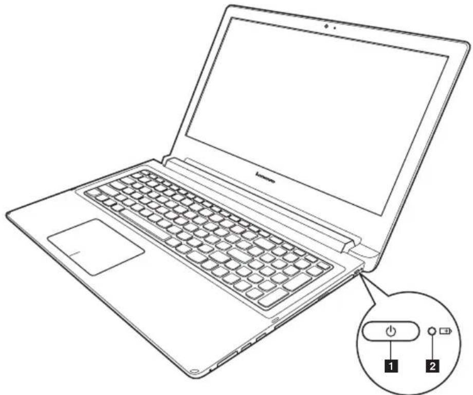
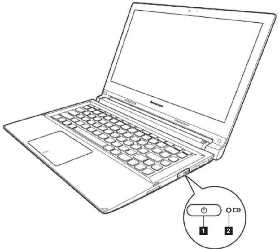
The system status indicators below show the computer status:
Flex 2-15/Flex 2-15D:
natural_image
Line drawing of a laptop with a close-up inset showing the keyboard and two labeled buttons (1 and 2) — no text or symbols on the device itself.Flex 2-14/Flex 2-14D:
text_image
Line drawing of a laptop with labeled buttons and a power switch icon for function callTable 2. Status indicators
| Indicator Indicator | status | Charge Status | Meaning |
| Power status indicator | On (solid white) | — | T h e c |
| Blinking — | The computer is in sleep mode. | ||
| Off — The computer is powered off. | |||
| Battery status indicator | On (solid white) | Discharging | The battery has more than 20% charge. |
| Solid amber | Discharging | The battery has between 5% and 20% charge. | |
| Fast blinking amber | Charging/ Discharging | The battery has less than 5% charge. | |
| Slow blinking amber | Charging The battery is being charged. When battery charge reaches 20%, the blinking color changes to white. | ||
| Slow blinking white | Charging The battery has between 20% and 80% charge and is still charging. When the battery reaches 80% charge the light will stop blinking, but charging will continue until the battery is fully charged. | ||
Hotkeys
The hotkeys are located in the function key row of the keyboard. By pressing the appropriate hotkey, you can change system settings instantly.
The following describes the function of each hotkey.
Table 3. Hotkeys
| Mutes/unmutes the sound. | Enables/disables airplane mode. | ||
| Decreases the volume level. | Switches the active program. | ||
| Increases the volume level. | Turns on/off the backlight of the display. | ||
| Closes the currently active window. | Projects to a connected display. | ||
| Refreshes the desktop or the currently active window. | Decreases display brightness. | ||
| Enables/disables the touch pad and the touch pad buttons. | Increases display brightness. |
FRU replacement notices
This section presents notices related to removing and replacing parts. Read this section carefully before replacing any FRU.
Screw notices
Loose screws can cause a reliability problem. In the Lenovo computer, this problem is addressed with special nylon-coated screws that have the following characteristics:
• They maintain tight connections.
- They do not easily come loose, even with shock or vibration.
• They are harder to tighten.
• Each one should be used only once.
Do the following when you service this machine:
- Keep the screw kit in your tool bag.
- Remove screws carefully for reuse.
- Use a torque screwdriver if you have one.
Tighten screws as follows:
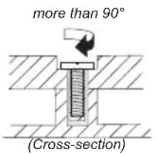
- Plastic to plastic
Turn an additional 90^ after the screw head touches the surface of the plastic part:
text_image
more than 90° (Cross-section)- Logic card to plastic
Turn an additional 180^ after the screw head touches the surface of the logic card:
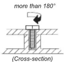
text_image
more than 180° (Cross-section)If you have a torque screwdriver, refer to the "Torque" column for each step.
- Make sure that you use the correct screws. If you have a torque screwdriver, tighten all screws firmly to the torque shown in the table. Never use a screw that you removed. Use a new one. Make sure that all screws are tightened firmly.
- Ensure torque screwdrivers are calibrated correctly following country specifications.
- Torque driver
Removing and replacing an FRU
This section presents exploded figures with the instructions to indicate how to remove and replace the FRU. Make sure to observe the following general rules:
- Do not attempt to service any computer unless you have been trained and certified. An untrained person runs the risk of damaging parts.
- Before replacing any FRU, review "FRU replacement notices" on page 32.
- Begin by removing any FRUs that have to be removed before the failing FRU. Any of such FRUs are listed at the top of the page. Remove them in the order in which they are listed.
- Follow the correct sequence in the steps to remove the FRU, as given in the figures by the numbers in square callouts.
- When turning a screw to replace an FRU, turn it in the direction as given by the arrow in the figure.
- When removing the FRU, move it in the direction as given by the arrow in the figure.
- To put the new FRU in place, reverse the removal procedures and follow any of the notes that pertain to replacement. For information about connecting and arranging internal cables, see "Locations" on page 70.
- When replacing an FRU, use the correct screw as shown in the procedures.

DANGER
Before removing any FRU, turn off the computer, unplug all power cords from electrical outlets, remove the battery pack, and then disconnect any of the interconnecting cables.
Attention: After replacing an FRU, do not turn on the computer until you have made sure that all screws, springs, and other small parts are in place and none are loose inside the computer. Verify this by shaking the computer gently and listening for rattling sounds. Metallic parts or metal flakes can cause electrical short circuits.
Attention: The system board is sensitive to, and can be damaged by, electrostatic discharge. Before touching it, establish personal grounding by touching a ground point with one hand or using an electrostatic discharge (ESD) strap (P/N 6405959) to remove potential shock reasons.
Note: The illustrations used in this section are of the Lenovo Ideapad Flex 2-15/Flex 2-15D, unless otherwise stated.

Lenovo Flex 2-14/Flex 2-14D/Flex 2-15/Flex 2-15D Hardware Maintenance Manual
1010 Keyboard
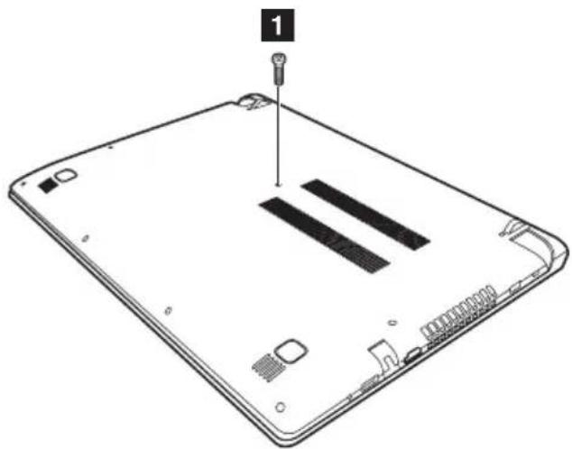
Figure 1. Removal steps of keyboard
Remove screw .1
natural_image
Diagram of a tablet device showing the front panel and internal components (no text or symbols)| Step Screw (quantity) Color Torque | |||
| 1 | M2.0 × 6 mm, flat-head, nylok-coated (1) (Flex 2-14/Flex 2-14D) | Black | 18~2.0 kgfcm |
| M2.0 × 6 mm, flat-head, nylok-coated(1) (Flex 2-15/Flex 2-15D) | Black | 1.85+/-0.15 kgfcm | |
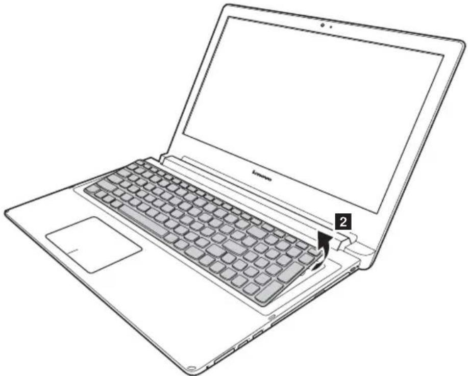
Loosen the keyboard with fingers in the direction shown by arrow 2
natural_image
Line drawing of a laptop with a keyboard and mouse, showing front panel and side panel (no text or symbols)Figure 1. Removal steps of keyboard (continued)
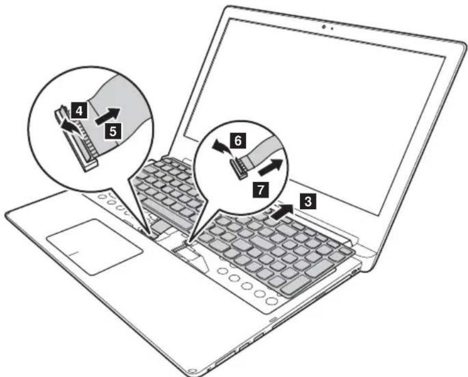
Lift the keyboard a little 3 and then detach the connector in the direction shown by arrows 4, 5, 6, 7
text_image
Diagram of a laptop with numbered callouts showing internal components: 3, 4, 5, 6, and 7.When installing: Make sure that the FPC connectors are attached firmly.

Lenovo Flex 2-14/Flex 2-14D/Flex 2-15/Flex 2-15D Hardware Maintenance Manual
1020 Optical drive
For access, remove this FRU:
- "1010 Keyboard" on page 34
Figure 2. Removal steps of optical drive
Remove the screw 1 insert a screwdriver into the screw hole and push the optical drive in the direction shown by arrow . 2 all the optical drive out in the direction shown by arrow 3
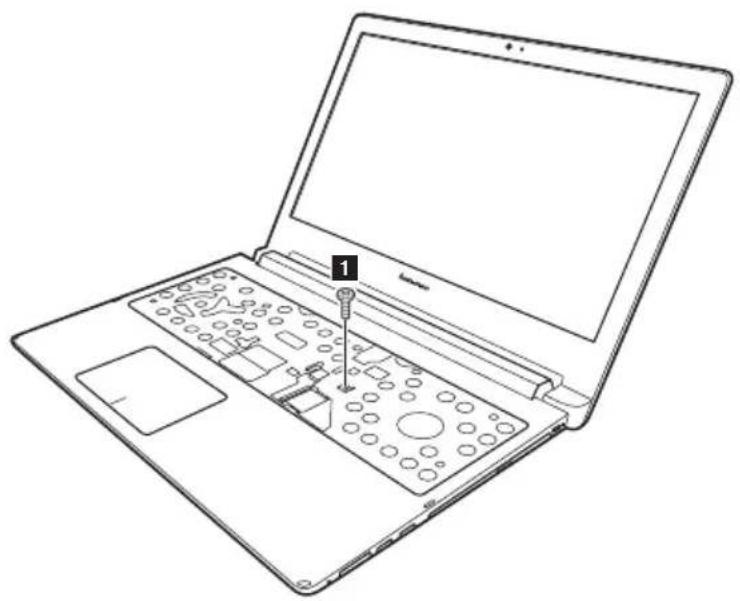
natural_image
Line drawing of a laptop with a labeled component (number 1) inserted into the interior, showing internal circuitry and control buttons.| Step Screw (quantity) Color Torque | |||
| 1 | M2 × 6 mm, flat-head, nylokcoated(1) (Flex 2-15/Flex 2-15D) | Black 1.85+/-0.15 kgfcm | |
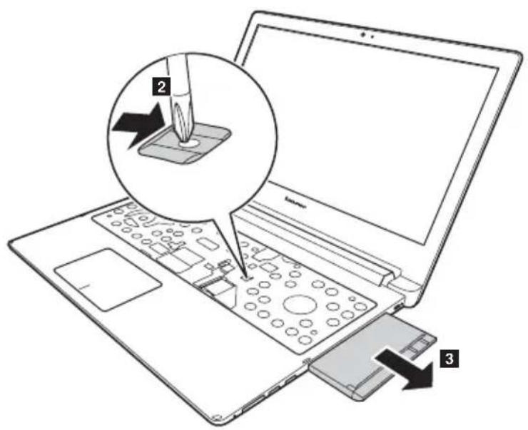
text_image
Diagram showing a laptop with a screwdriver inserted into a control panel, labeled with parts 2 and 3.1030 Hard disk drive(HDD)/Memory/Mini PCI Express Card slot compartment cover
For access, remove these FRUs in order:
• "1010 Keyboard" on page 34
- "1020 Optical drive" on page 36
Figure 3. Removal steps of HDD/Memory/Mini PCI Express Card slot compartment cover
Loosen the screws 1 and 2 that secure the compartment cover. Remove the compartment cover 4
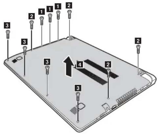
text_image
Diagram of a tablet with numbered pins indicating internal components and an upward arrow pointing to component 4.| Step Screw (quantity) Color Torque | |||
| 1 | M2 × 6 mm, flat-head, nylok-coated (8) (Flex 2-14/Flex 2-14D) | Black | 18~2.0 kgfcm |
| M2 × 3.5 mm, flat-head, nylok-coated (4) (Flex 2-15/Flex 2-15D) | Black | 1.85+/-0.15 kgfcm | |
| M2 × 6 mm, flat-head, nylok-coated (4) (Flex 2-15/Flex 2-15D) | Black | 1.85+/-0.15 kgfcm | |
| M2 × 2 mm, flat-head, nylok-coated (3) (Flex 2-15/Flex 2-15D) | Black | 1.85+/-0.15 kgfcm | |

Lenovo Flex 2-14/Flex 2-14D/Flex 2-15/Flex 2-15D Hardware Maintenance Manual
Remove screws 5
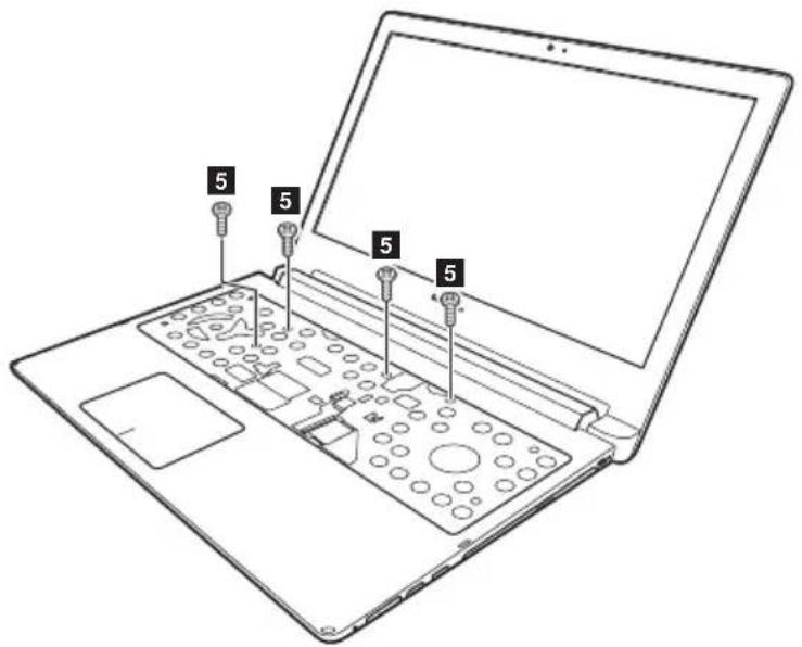
text_image
5 5 5 5| Step Screw (quantity) Color Torque | ||||
| 1 | M2 × 3.5 mm, flat-head, nylok-coated (4) | Black | 1.85+/-0.15 | kgfcm |
1040 Battery pack
For access, remove these FRUs in order:
• "1010 Keyboard" on page 34
• "1020 Optical drive" on page 36
- "1030 Hard disk drive(HDD)/Memory/Mini PCI Express Card slot compartment cover" on page 37

DANGER
Only use the battery specified in the parts list for your computer. Any other battery could ignite or explode.
Figure 4. Removal steps of battery pack
Remove screws 1 Unplug connector in the direction shown by arrow . 2 Remove the battery pack in the direction shown by the arrow 3
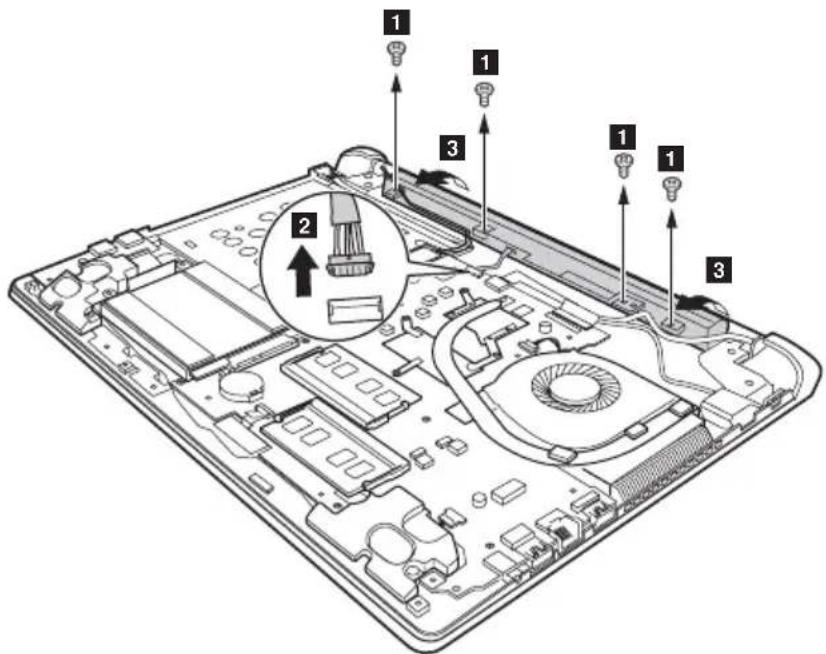
text_image
Labeled diagram of a laptop chassis showing internal components with numbered parts and an inset magnified view highlighting a component.| Step Screw (quantity) Color Torque | |||
| 1 | M2 × 4 mm, flat-head, nylok-coated (4) (Flex 2-14/2-14D) | Silver | 1.8~2.0 kgfcm |
| M2 × 3.5 mm, flat-head, nylok-coated (4) (Flex 2-15/2-15D) | Black | 1.85+/-0.15 kgfcm | |
©
Pull the tab in the direction shown by arrow . 2

natural_image
Technical line drawing of an open laptop chassis showing internal components and circuitry (no text or symbols)Take out the hard disk drive secured in a metal frame in the direction shown by arrow 3.
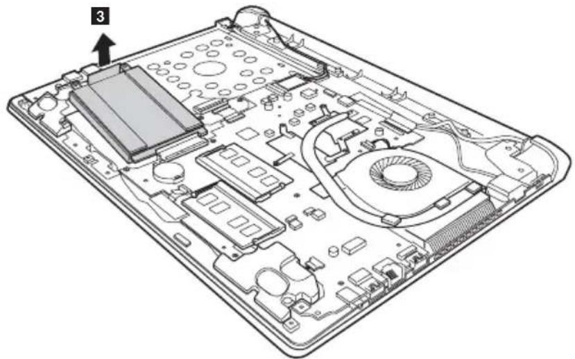
natural_image
Technical line drawing of an open laptop chassis showing internal components and circuitry (no text or symbols)Remove four screws and detach the metal frame from the hard disk drive.
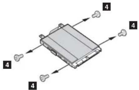
natural_image
Diagram of a mechanical component with four numbered parts and directional arrows indicating flow or movement (no text or symbols present)| Step Screw (quantity) Color Torque | |||
| 3 | M3.0 × 4 mm, flat-head, nylok-coated (4) (Flex 2-14/2-14D) | Silver | 1.8~2.0 kgfcm |
| M3.0 × 3.0 mm, flat-head, nylok-coated (4) (Flex 2-15/2-15D) | Black | 3.0+/-0.3 kgfcm | |
When installing: Make sure that the HDD connector is attached firmly.
Lenovo Flex 2-14/Flex 2-14D/Flex 2-15/Flex 2-15D Hardware Maintenance Manual
1060 DIMM
For access, remove these FRUs in order
- "1010 Keyboard" on page 34
- "1020 Optical drive" on page 36
- "1030 Hard disk drive(HDD)/Memory/Mini PCI Express Card slot compartment cover" on page 37
- "1040 Battery pack" on page 39
Figure 6. Removal steps of DIMM
Release the two latches on both edges of the socket at the same time in the direction shown by arrows 1 and then unplug the DIMM in the direction shown by arrow 2
1
1
2
When installing: Insert the notched end of the DIMM into the socket. Push the DIMM firmly, and pivot it until it snaps into the place. Make sure that it is firmly fixed in the slot and difficult to be moved.
1070 PCI Express Mini Card for wireless LAN/WAN
For access, remove these FRUs in order
• "1010 Keyboard" on page 34
• "1020 Optical drive" on page 36
- "1030 Hard disk drive(HDD)/Memory/Mini PCI Express Card slot compartment cover" on page 37
• "1040 Battery pack" on page 39
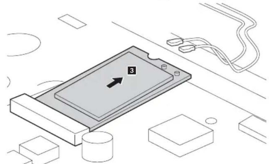
Figure 7. Removal steps of PCI Express Mini Card for wireless LAN/WAN
Disconnect the two wireless LAN cables (black, white), and then remove the screw 2.
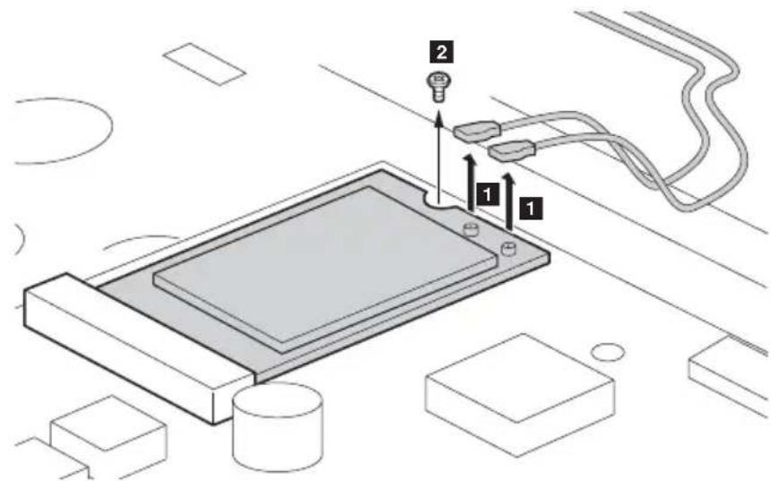
text_image
Technical diagram showing a device with labeled parts and connections, including numbered components 1 and 2.In step 1 nplug the jacks by using the removal tool antenna RF connector (P/N: 08K7159), or pick up the connectors with your fingers and gently unplug them in the direction shown by arrows.
Notes: wireless LAN card has 2 cables in step 1
wireless LAN card in some models may have 3 cables in step 1
| Step Screw (quantity) Color Torque | |||
| 2 | M2 × 3.0 mm, flat-head, nylok-coated(1) (Flex 2-14/2-14D) | Black | 1.5~1.8 kgfcm |
| M2 × 3.5 mm, flat-head, nylok-coated(1) (Flex 2-15/2-15D) | Black | 1.85+/-0.15kgfcm | |

Lenovo Flex 2-14/Flex 2-14D/Flex 2-15/Flex 2-15D Hardware Maintenance Manual
Figure 7. Removal steps of PCI Express Mini Card for wireless LAN/WAN (continued) Remove the card in the direction shown by arrow 3
natural_image
Isometric diagram of a computer monitor with labeled components and an arrow pointing to a screen (no text or symbols present)When installing:
- In models with a wireless LAN card that has two antenna connectors, plug the black cable (1st) (MAIN) into the jack labeled 1, and the white cable (2nd) (AUX) into jack labeled 2 on the card.
- In models with a wireless LAN card that has three antenna connectors, plug the black cable (1st) (MAIN) into the jack labeled 1, the grey cable (3rd) into jack labeled 3, and the white cable (2nd) (AUX) into jack labeled 2 on the card.
1080 Fan assembly and Heat Sink assembly
For access, remove these FRUs in order:
• "1010 Keyboard" on page 34
• "1020 Optical drive" on page 36
- "1030 Hard disk drive(HDD)/Memory/Mini PCI Express Card slot compartment cover" on page 37
• "1040 Battery pack" on page 39
• "1050 Hard disk drive" on page 40
• "1060 DIMM" on page 42
- "1070 PCI Express Mini Card for wireless LAN/WAN" on page 43
Figure 8. Removal steps of fan assembly and heat sink assembly
Loosen screws 1
Flex 2-14/Flex 2-14D:
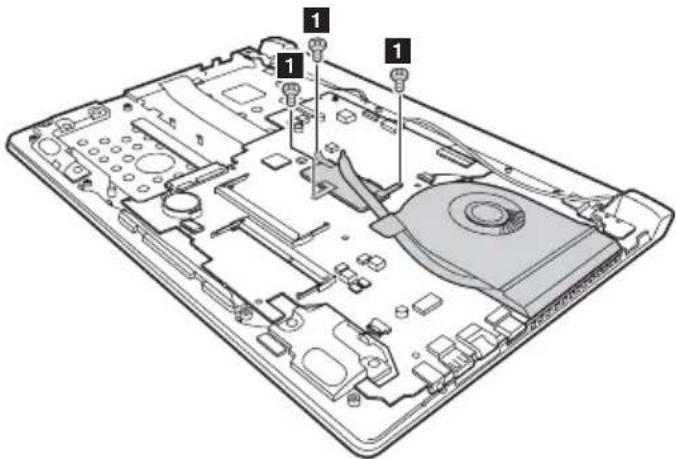
text_image
Technical diagram of an electronic device showing internal components with numbered labels
Lenovo Flex 2-14/Flex 2-14D/Flex 2-15/Flex 2-15D Hardware Maintenance Manual
Flex 2-15/Flex 2-15D:
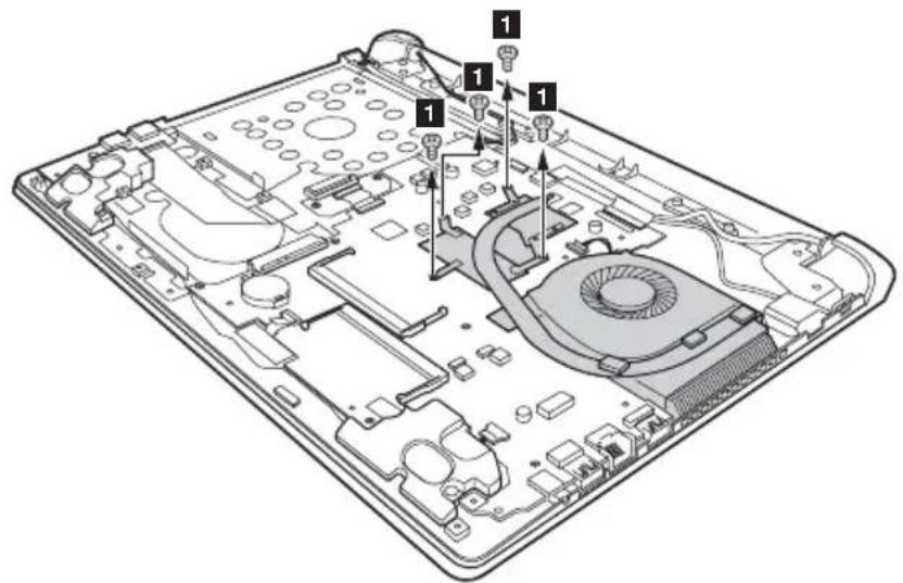
text_image
Technical diagram of an electronic device with labeled components and numbered partsFigure 8. Removal steps of fan assembly and heat sink assembly (continued) Unplug the fan connector in the direction shown by arrow 2
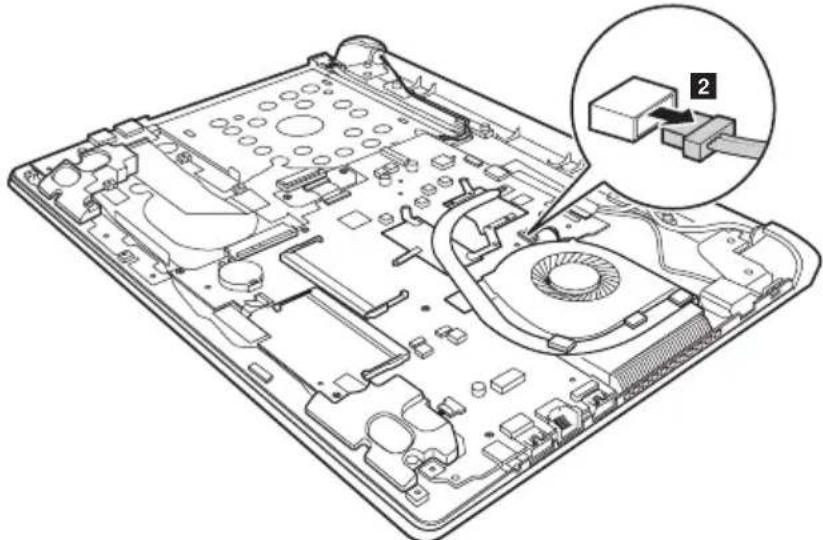
natural_image
Technical line drawing of an electronic device chassis with a magnified inset showing a component labeled '2' (no text or symbols present)When installing: Make sure that the fan connector is attached firmly to the system board.
Lift the fan assembly in the direction shown by arrow . 3 careful not to damage the connector.
Flex 2-14/Flex 2-14D:
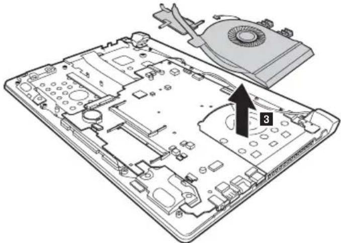
natural_image
Technical diagram of an electronic device casing with internal components and a labeled component (no text or symbols present)
Lenovo Flex 2-14/Flex 2-14D/Flex 2-15/Flex 2-15D Hardware Maintenance Manual
Flex 2-15/Flex 2-15D:
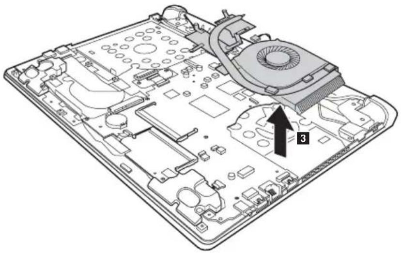
natural_image
Technical diagram of an electronic device casing with internal components and a numbered annotation (3), showing no readable text or symbols.1090 System board
Important notices for handling the system board:
When handling the system board, bear the following in mind.
- Be careful not to drop the system board on a bench top that has a hard surface, such as metal, wood, or composite.
- Avoid rough handling of any kind.
- In the whole process, make sure not to drop or stack the system board.
- If you put a system board down, make sure to put it only on a padded surface such as an ESD mat or conductive corrugated material.
For access, remove these FRUs in order:
- "1010 Keyboard" on page 34
- "1020 Optical drive" on page 36
- "1030 Hard disk drive(HDD)/Memory/Mini PCI Express Card slot compartment cover" on page 37
- "1040 Battery pack" on page 39
- "1050 Hard disk drive" on page 40
• "1060 DIMM" on page 42 - "1070 PCI Express Mini Card for wireless LAN/WAN" on page 43
- "1080 Fan assembly and Heat Sink assembly" on page 45

Lenovo Flex 2-14/Flex 2-14D/Flex 2-15/Flex 2-15D Hardware Maintenance Manual
Figure 9. Removal steps of system board (continued)
Flex 2-15/Flex 2-15D: Remove five screws 1
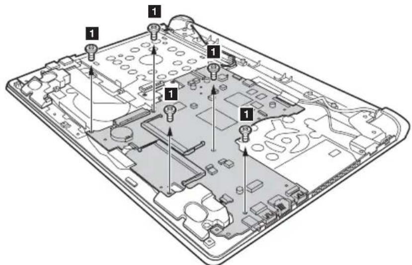
text_image
Labeled diagram of a device interior showing internal components with numbered calloutsFlex 2-14/Flex 2-14 D: Remove two screws and five screws.
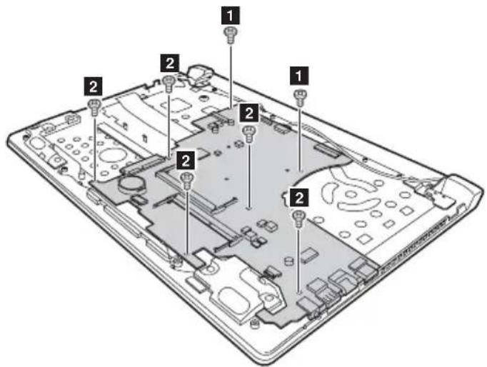
text_image
Labeled diagram of a smartphone showing internal components with numbered parts| Step Screw (quantity) Color Torque | |||
| 1 | M2 × 3 mm, flat-head, nylok-coated (2)(Flex 2-14/Flex 2-14D) | Black | 1.5~1.8 kgfcm |
| M2 × 4 mm, flat-head, nylok-coated (5)(Flex 2-14/Flex 2-14D) | Silver | 1.8~2.0 kgfcm | |
| M2.0 × 3.5 mm, flat-head, nylok-coated (5)(Flex 2-15/Flex 2-15D) | Black | 1.85+/-0.15 kgfcm | |
Figure 9. Removal steps of system board (continued)
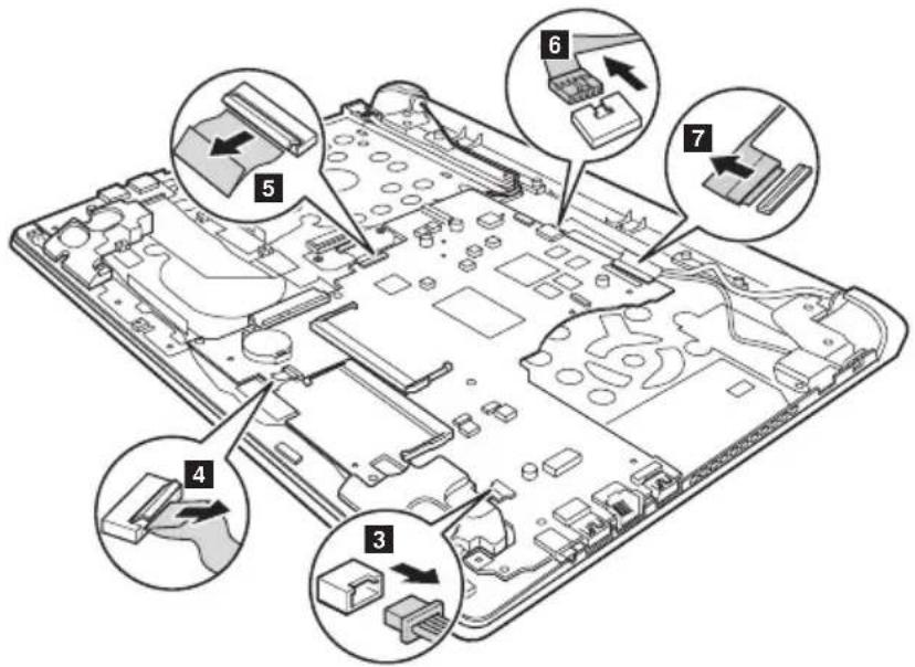
Flex 2-15/Flex 2-15D: Unplug DC-IN cable connector in the direction shown by arrow 6 speakers connector in the direction shown by arrow , de 3 h ODD transfer board connector in the direction shown by arrow 5 touch pad connector in the direction shown by arrow 4 isconnect LCD connector in the direction shown by arrow 7
text_image
Technical diagram of an electronic device with numbered components, likely illustrating a circuit board layout or assembly.Flex 2-14/Flex 2-14 D: Unplug DC-IN cable connector in the direction shown by arrow 6 speakers connector in the direction shown by arrow , dc3ch touch pad connector in the direction shown by arrow 4 disconnect LCD connector in the direction shown by arrow 5

text_image
Diagram of a device's internal components with numbered labels indicating parts of each part.When installing: Make sure that all the connectors are attached firmly.

Lenovo Flex 2-14/Flex 2-14D/Flex 2-15/Flex 2-15D Hardware Maintenance Manual
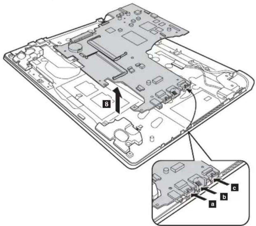
Remove the system board in the direction shown by arrow .8
text_image
8 a b cWhen installing: When attaching the system board to the base cover, adjust the placement of the USB, RJ-45, HDMI ports as shown in a b n c ke sure that they are attached to the holes on the base cover as shown. Improper placement of those jacks might cause a damage.
1100 LCD unit
For access, remove these FRUs in order
• "1010 Keyboard" on page 34
• "1020 Optical drive" on page 36
- "1030 Hard disk drive(HDD)/Memory/Mini PCI Express Card slot compartment cover" on page 37
• "1040 Battery pack" on page 39
• "1050 Hard disk drive" on page 40
• "1060 DIMM" on page 42
- "1070 PCI Express Mini Card for wireless LAN/WAN" on page 43
- "1080 Fan assembly and Heat Sink assembly" on page 45
• "1090 System board" on page 49
Figure 10. Removal steps of LCD unit
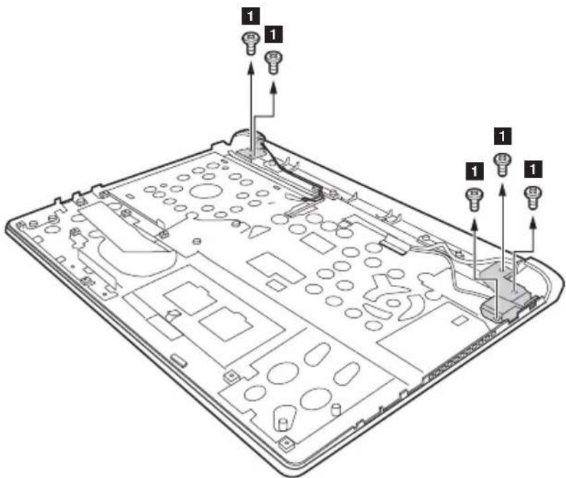
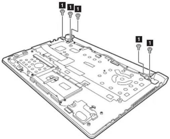
Remove five screws .1
Flex 2-15/Flex 2-15D:
text_image
Technical diagram of an electronic device with labeled components and lightbulb indicators
Lenovo Flex 2-14/Flex 2-14D/Flex 2-15/Flex 2-15D Hardware Maintenance Manual
Flex 2-14/Flex 2-14 D:
text_image
Labeled diagram of an electronic device showing internal components with numbered parts| Step Screw (quantity) Color Torque | |||
| 1 | M2.5 × 4 mm, flat-head, nylok-coated (5) (Flex 2-14/Flex 2-14D) | Silver | 18~2.0 kgfcm |
| M2.5 × 4.5 mm, flat-head,nylok-coated (4) (Flex 2-15/Flex 2-15D) | Silver | 3.0+/-0.3 kgfcm | |
| M2.5 × 4.5 mm, flat-head,nylok-coated (Flex 2-15/Flex 2-15D) | Silver | 3.0+/-0.3 kgfcm | |
| M2.0 × 3.5 mm, flat-head,nylok-coated (Flex 2-15/Flex 2-15D) | Black | 1.85+/-0.15 kgfcm | |
When installing:
- Route the antenna cables along the cable guides. As you route the cables, make sure that they are not subjected to any tension. Tension could cause the cables to be damaged by the cable guides, or a wire to be broken.
- Make sure that the LCD connector is attached firmly and make sure that you do not pinch the antenna cables when you attach the LCD assembly. Route the LCD cable along the cable guides.
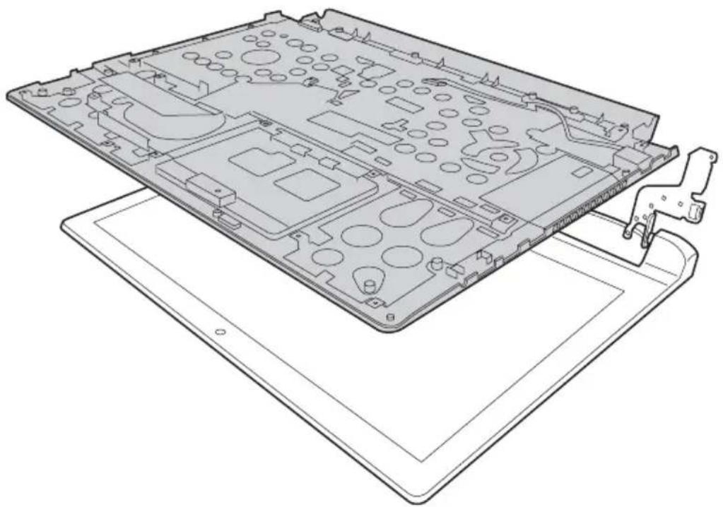
Figure 10. Removal steps of LCD unit (continued) Detach the LCD unit from the upper case.
natural_image
Technical line drawing of a laptop chassis showing internal components and casing (no text or symbols)1110 Speakers, base cover, IO board, DC-IN, power board and ODD transfer board
For access, remove these FRUs in order:
• "1010 Keyboard" on page 34
• "1020 Optical drive" on page 36
- "1030 Hard disk drive(HDD)/Memory/Mini PCI Express Card slot compartment cover" on page 37
• "1040 Battery pack" on page 39
• "1050 Hard disk drive" on page 40
- "1060 DIMM" on page 42
- "1070 PCI Express Mini Card for wireless LAN/WAN" on page 43
- "1080 Fan assembly and Heat Sink assembly" on page 45
• "1090 System board" on page 49
• "1100 LCD unit" on page 53
Figure 11. Speakers, base cover, IO board, DC-IN, power board and ODD transfer board Remove screws ① and then remove the speakers in the direction shown by arrows ②.
Flex 2-15/Flex 2-15 D:
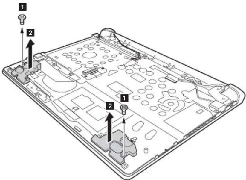
text_image
Technical diagram of a device's internal components with numbered parts and directional arrows indicating assembly or assembly.Flex 2-14/Flex 2-14 D:
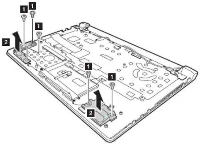
text_image
Labeled diagram of a laptop chassis showing internal components with numbered parts| Step Screw (quantity) Color Torque | |||
| 1 | M2 × 3.1 mm, flat-head, nylok-coated (2) (Flex 2-15/Flex 2-15D) | Black | 1.85+/-0.15 kgfcm |
| M2.0 × 6.8 mm, flat-head, nylok-coated (3) (Flex 14) | Black | 1.85+/-0.2 kgfcm | |
| M2.0 × 5.5 mm, flat-head, nylok-coated (2) (Flex 15) | Black | 1.85+/-0.15 kgfcm | |
| M2.0 × 6.8 mm, flat-head, nylok-coated (2) (Flex 15) | Black | 1.85+/-0.15 kgfcm | |

Lenovo Flex 2-14/Flex 2-14D/Flex 2-15/Flex 2-15D Hardware Maintenance Manual
Figure 11. Speakers, base cover, IO board, DC-IN, power board and ODD transfer board (continued)
Remove the DC-IN in the direction shown by arrow .1
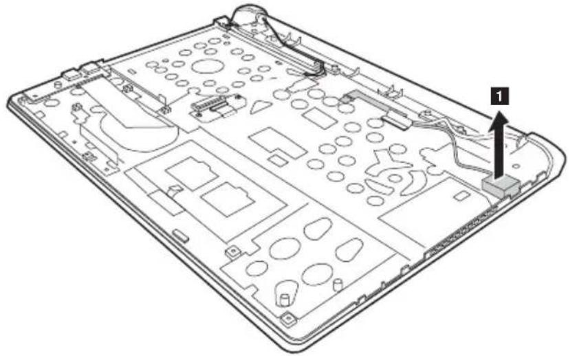
natural_image
Technical line drawing of a device chassis with labeled components (no text or symbols beyond label)When installing: Make sure that the power connector is attached firmly.
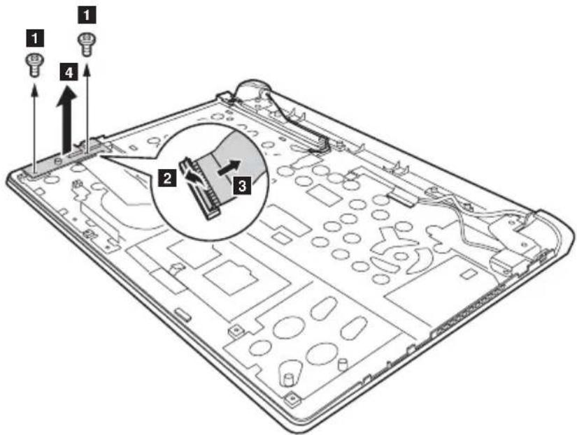
Flex 2-15/Flex 2-15 D: Remove screws 1 detach connector in the direction shown by arrows 2 and 3 then remove the IO board in the direction shown by arrow 4
text_image
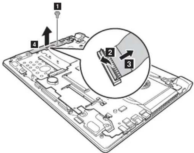
Diagram of a device's internal structure with numbered components and directional arrows indicating assembly or assembly.Flex 2-14/Flex 2-14 D: Remove screw 1 etach connector in the direction shown by arrows 2 and 3 then remove the function board in the direction shown by arrow 4
text_image
Diagram of a computer motherboard with numbered components and an inset showing a close-up of a component labeled 2 and 3.| Step Screw (quantity) Color Torque | |||
| 1 | M2 × 4 mm, flat-head, nylok-coated (1) (Flex 2-14/Flex 2-14D) | Silver | 18~2.0 kgfcm |
| M2.0 × 3.5 mm, flat-head, nylok-coated (2) (Flex 2-15/Flex 2-15D) | Black | 1.85+/-0.15 kgfcm | |

Lenovo Flex 2-14/Flex 2-14D/Flex 2-15/Flex 2-15D Hardware Maintenance Manual
Figure 11. Speakers, base cover, IO board, DC-IN, power board and ODD transfer board (continued)
When installing: When attaching the audio board to the base cover, adjust the placement of the USB and headphone jacks as shown, and make sure that both of the USB and the headphone jacks are attached to the holes on the base cover. Improper placement of the jacks might cause a damage.
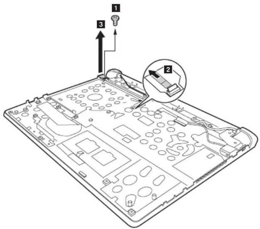
Remove screw 1 etach the connector to 2 the power board in the direction shown by arrow 3
text_image
Diagram of an electronic device with labeled components and directional arrows indicating assembly or operation.| Step Screw (quantity) Color Torque | |||
| 1 | M2.0 × 3.5 mm, flat-head, nylok-coated (1)(Flex 2-15/Flex 2-15D) | Black 1.85+/-0.15kgfcm | |
Figure 11. Speakers, base cover, IO board, DC-IN, power board and ODD transfer board (continued)
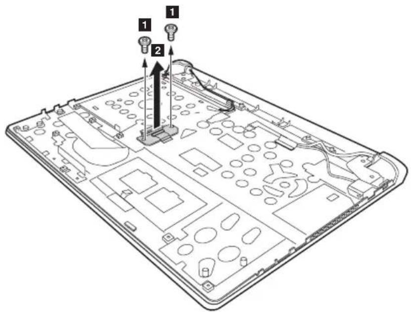
Remove screws 1 lift the ODD transfer board in the direction shown by arrow 2.
text_image
Technical diagram of an electronic device with labeled components and directional arrows indicating assembly or installation.| Step Screw (quantity) Color Torque | |||
| 1 | M2.0 × 3.5 mm, flat-head, nylok-coated (2)(Flex 2-15/Flex 2-15D) | Black 1.85+/-0.15kgfcm | |
Applying labels to the base cover
The new base cover FRU is shipped with a kit containing labels of several kinds. Apply those labels when you replace the base cover. For labels which are not shipped with the new base cover, peel them from the replaced base cover and adhere them to the new one.
Note: If the Certificate of Authenticity (COA) label (b) is attached to a replaced part, return the replaced part to the customer, or provide a letter to the customer stating the original label part number, serial number, and product key.
Flex 2-14/Flex 2-14 D:
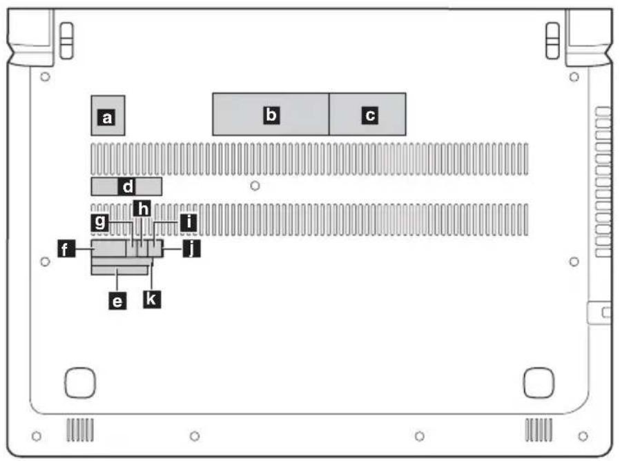
text_image
a b c d g h i f j e kThe following letter shows the correct location of each label. Not all labels are attached on the part you are servicing.
a GML label
b Rating label-1
C Rating label-2
d Barcode label
e WLAN Label for US/CA/TW
f WLAN Label for South Africa
g D Side label for Indonesia
BT Label for US/CA/TW or WLAN/BT Label for Isarel
KCC Label for Korea or BIS Label for India
j Postel Label for Indonesia
k WL/BT Label for Brazil
Flex 2-15/Flex 2-15 D:
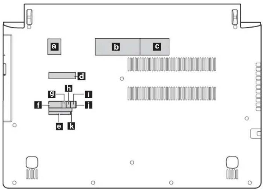
text_image
a b c d g h i f i e kThe following letter shows the correct location of each label. Not all labels are attached on the part you are servicing.
a GML label
b Rating label-1
C Rating label-2
d Barcode label
e WLAN Label for US/CA/TW
f WLAN Label for South Africa
g D Side label for Indonesia
BT Label for US/CA/TW or WLAN/BT Label for Isarel
KCC Label for Korea or BIS Label for India
Postel Label for Indonesia
k WL/BT Label for Brazil
1120 LCD front bezel
For access, remove these FRUs in order:
- "1010 Keyboard" on page 34
- "1020 Optical drive" on page 36
- "1030 Hard disk drive(HDD)/Memory/Mini PCI Express Card slot compartment cover" on page 37
• "1040 Battery pack" on page 39
- "1050 Hard disk drive" on page 40
- "1060 DIMM" on page 42
- "1070 PCI Express Mini Card for wireless LAN/WAN" on page 43
- "1080 Fan assembly and Heat Sink assembly" on page 45
• "1090 System board" on page 49
- "1100 LCD unit" on page 53
- "1110 Speakers, base cover, IO board, DC-IN, power board and ODD transfer board" on page 56
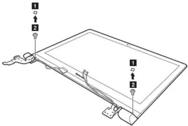
Figure 12. Removal steps of LCD front bezel
Remove LCD bezel screw pad 1 and the screws . 2
text_image
Diagram of a tablet device with labeled parts and connectors, showing two numbered components and cable routing.| Step | Screw (quantity) | Color | Torque |
| 1 | M2.5 X 4.0 (2), flat-head, nylok-coated (Flex 2-14/Flex 2-14D) | Silver | 18~2.0 kgfcm |
| M2.5 X 4.5 (2), flat-head,nylokcoated (Flex 2-15/Flex 2-15D) | Silver | 3.0+/-0.3 kgfcm |
Remove the LCD bezel cover in the direction shown by arrows . 3
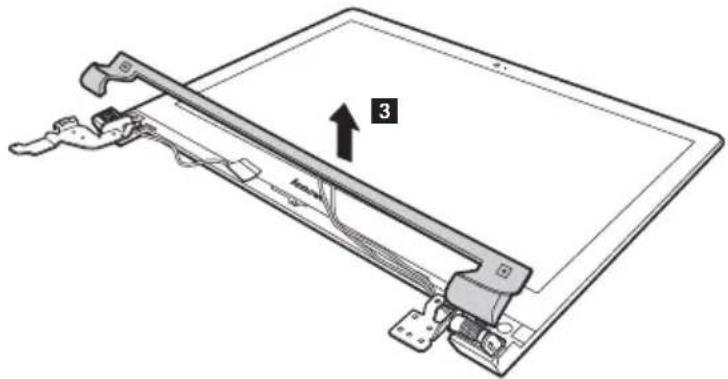
natural_image
Technical line drawing of a device with a labeled component '3' and cable connectors (no text or symbols beyond the number)Remove screw 4 remove the LCD front bezel.
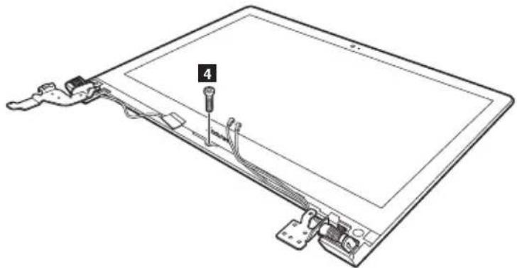
natural_image
Line drawing of a tablet device with labeled components (no text or symbols present)| Step Screw (quantity) Color Torque | |||
| 1 | M2.5 X 4.0 (1), flat-head,nylok-coated (Flex 2-14/Flex 2-14D) | Silver | 18~2.0 kgfcm |
| M2.0 X 3.5 (1), flat-head,nylok-coated (Flex 2-15/Flex 2-15D) | Black | 1.85+/-0.15 kgfcm | |
1130 LCD panel, LCD cable and hinges
For access, remove these FRUs in order:
• "1010 Keyboard" on page 34
• "1020 Optical drive" on page 36
- "1030 Hard disk drive(HDD)/Memory/Mini PCI Express Card slot compartment cover" on page 37
• "1040 Battery pack" on page 39
- "1050 Hard disk drive" on page 40
• "1060 DIMM" on page 42
- "1070 PCI Express Mini Card for wireless LAN/WAN" on page 43
- "1080 Fan assembly and Heat Sink assembly" on page 45
• "1090 System board" on page 49
• "1100 LCD unit" on page 53
- "1110 Speakers, base cover, IO board, DC-IN, power board and ODD transfer board" on page 56
• "1120 LCD front bezel" on page 64
Figure 13. LCD panel, LCD cable and hinges
Unplug connector 1 disconnect connector to 2 the LCD panel.
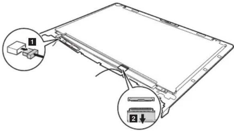
text_image
Diagram showing two labeled components (1 and 2) of a device or electronic component with connectors and wiring, likely illustrating a physical or mechanical assembly.When installing: Make sure that the connectors are attached firmly.
Remove four screws 1 two screws and 2 the hinges in the direction shown by arrows 3
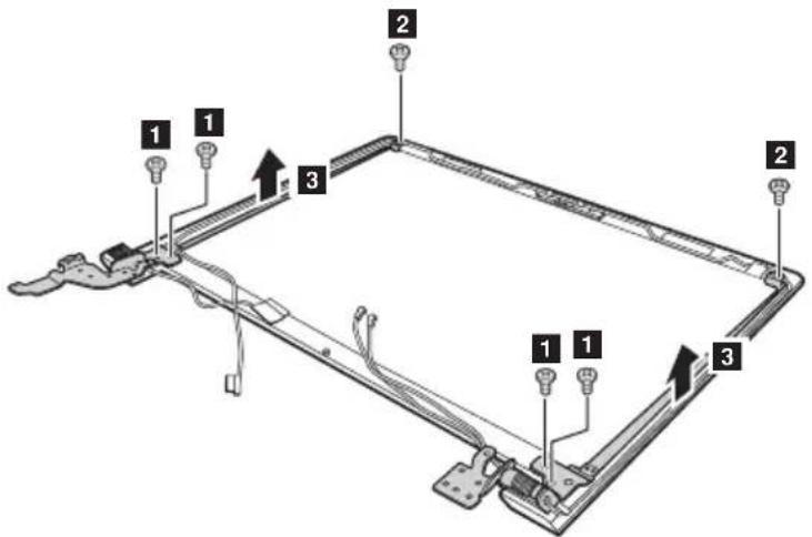
text_image
Technical diagram of a mechanical assembly with numbered components and directional arrows indicating assembly or movement.| Step Screw (quantity) Color Torque | |||
| 1 | M2.0 × 2 mm, flat-head, nylok-coated(2) (Flex 2-14/Flex 2-14D) | Black | 18~2.0 kgfcm |
| M2.5 × 2.5 mm, flat-head, nylok-coated(4) (Flex 2-14/Flex 2-14D) | Silver | 18~2.0 kgfcm | |
| M2.5 × 2.5 mm, flat-head, nylok-coated(6) (Flex 2-15/Flex 2-15D) | Silver | 3.0 +/-0.3 kgfcm | |

Lenovo Flex 2-14/Flex 2-14D/Flex 2-15/Flex 2-15D Hardware Maintenance Manual
1140 Integrated camera
For access, remove these FRUs in order:
• "1010 Keyboard" on page 34
• "1020 Optical drive" on page 36
- "1030 Hard disk drive(HDD)/Memory/Mini PCI Express Card slot compartment cover" on page 37
• "1040 Battery pack" on page 39
• "1050 Hard disk drive" on page 40
• "1060 DIMM" on page 42
- "1070 PCI Express Mini Card for wireless LAN/WAN" on page 43
- "1080 Fan assembly and Heat Sink assembly" on page 45
• "1090 System board" on page 49
• "1100 LCD unit" on page 53
- "1110 Speakers, base cover, IO board, DC-IN, power board and ODD transfer board" on page 56
• "1120 LCD front bezel" on page 64
- "1130 LCD panel, LCD cable and hinges" on page 66
Figure 14. Removal steps of integrated camera
Note: The integrated camera is stuck on the top center of the LCD cover.
Unplug the connector 1 remove the integrated camera from the LCD cover in the direction shown by arrow 2
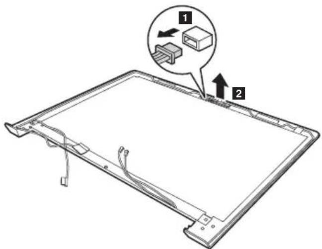
text_image
Technical diagram of a device with labeled components and directional arrows indicating assembly or assembly stepsWhen installing: Stick the integrated camera to the top center of the LCD cover and adjust the placement of it to make sure the connector is attached firmly.
1150 Antenna assembly and LCD cover
For access, remove these FRUs in order:
• "1010 Keyboard" on page 34
• "1020 Optical drive" on page 36
- "1030 Hard disk drive(HDD)/Memory/Mini PCI Express Card slot compartment cover" on page 37
• "1040 Battery pack" on page 39
• "1050 Hard disk drive" on page 40
• "1060 DIMM" on page 42
- "1070 PCI Express Mini Card for wireless LAN/WAN" on page 43
- "1080 Fan assembly and Heat Sink assembly" on page 45
• "1090 System board" on page 49
- "1100 LCD unit" on page 53
- "1110 Speakers, base cover, IO board, DC-IN, power board and ODD transfer board" on page 56
• "1120 LCD front bezel" on page 64
- "1130 LCD panel, LCD cable and hinges" on page 66
• "1140 Integrated camera" on page 68
Figure 15. Removal steps of antenna assembly and LCD cover
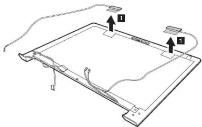
Peel off the adhesive tapes securing the antenna boards, release the cables from the cable guide, and then remove the antenna assembly in the direction shown by arrows 1
text_image
Diagram of a device with labeled components and connectors, showing a circuit board layout with arrows indicating connection points.When installing: Route the antenna cables along the cable guides and secure the antenna boards with adhesive tapes. As you route the cables, make sure that they are not subjected to any tension. Tension could cause the cables to be damaged by the cable guides, or a wire to be broken.
Locations
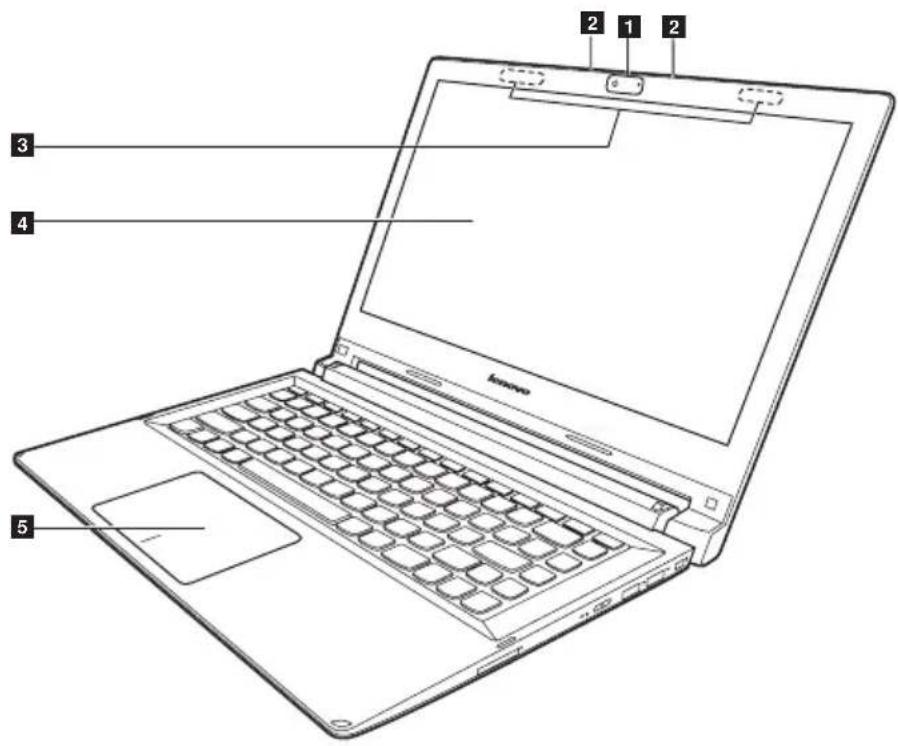
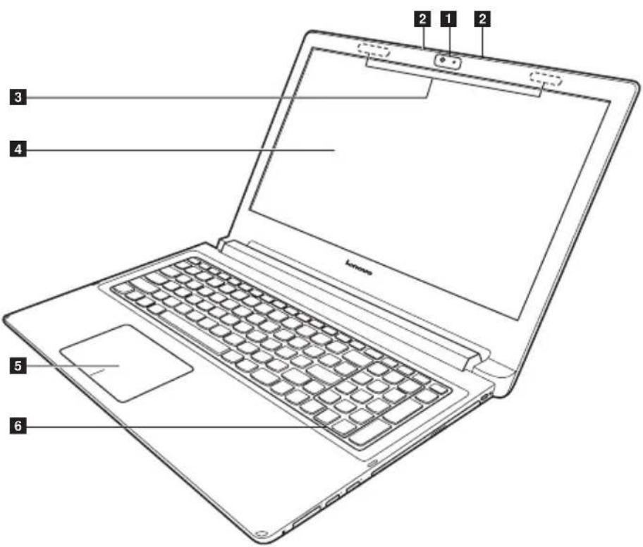
Front view
1 Integrated camera
2 Built-in microphone
3 Wireless antennas
4 Display
5 Touch pad
6 Numeric keypad (Flex 2-15/Flex 2-15D)
Flex 2-14/Flex 2-14D:
text_image
2 1 2 3 4 5Flex 2-15/Flex 2-15D:
text_image
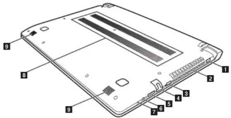
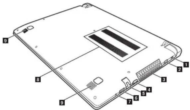
2 1 2 3 4 5 6Bottom and Left-side view
Flex 2-14/Flex 2-14D
1 AC power adapter jack
2 Ventilation slots
3 HDMI port
4 RJ-45 port
5 USB 3.0 port
6 Combo audio jack
7 Novo button
8 Ventilation slots
9 Speakers
text_image
Labeled diagram of a smartphone showing internal components with numbered partsFlex 2-15/Flex 2-15D
1 Kensington slot
2 AC power adapter jack
3 Ventilation slots
4 HDMI port
5 RJ-45 port
6 USB 3.0 port
7 Combo audio jack
8 Ventilation slots
9 Speakers
text_image
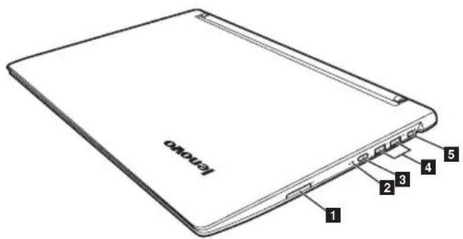
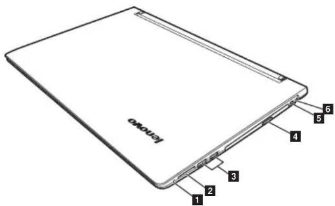
Labeled diagram of a tablet device showing internal components with numbered partsRight-side view
Flex 2-14/Flex 2-14D:
1 Memory card slot
2 Battery status indicator
3 Power button
4 USB ports
5 Kensington slot
text_image
I/O 1 2 3 4 5Flex 2-15/Flex 2-15D:
1 Novo button
2 Memory card slot
3 USB ports
4 Optical disc drive
5 Power button
6 Battery status indicator
text_image
LOXOVO 1 2 3 4 5 6Parts list
This section presents the following service parts:
- "Overall" on page 75
- "LCD FRUs" on page 85
- "Keyboard" on page 88
- "Miscellaneous parts" on page 99
- "AC adapters" on page 100
- "Power cords" on page 101
Notes:
- Each FRU is available for all types or models, unless specific types or models are specified.
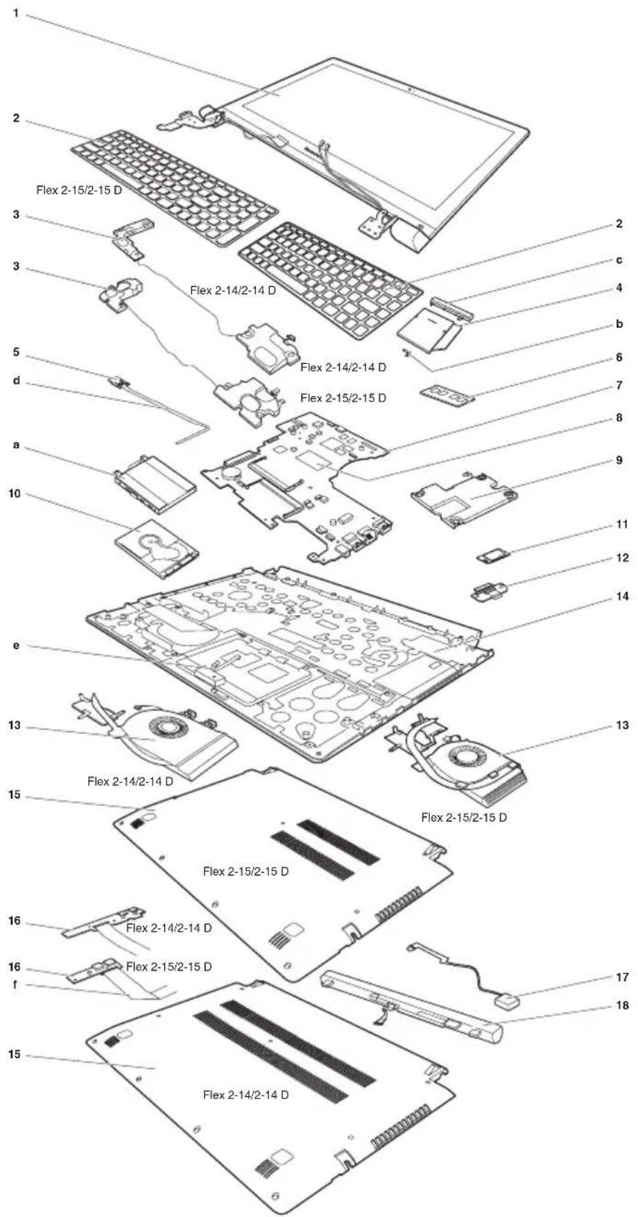
Overall
text_image
1 2 3 3 5 d a 10 e 13 15 16 f 16 17 18 Flex 2-15/2-15 D Flex 2-14/2-14 D Flex 2-14/2-14 D Flex 2-15/2-15 D Flex 2-15/2-15 D Flex 2-15/2-15 D Flex 2-14/2-14 D Flex 2-14/2-14 D Flex 2-14/2-14 D Flex 2-14/2-14 D Flex 2-14/2-14 D 2 c 4 b 6 7 8 9 11 12 14 13 Flex 2-15/2-15 DTable 4. Parts list—Overall (continued)
| No. FRU FRU no. CRU | ID | |
| 1 LCD unit (see “LCD FRUs” on page 73.) N | ||
| 2 Keyboard (see “Keyboard” on page 75.) ** | ||
| 3 SPEAKERINT Speaker W Flex2-14 (Flex 2-14/Flex 2-14D) | 5SB0F76730 | N |
| 3 SPEAKERINT Speaker W Flex2-15 (Flex 2-15/Flex 2-15D) | 5SB0F76735 | N |
| 4 ODD 9.0 Rambo HLDS GUA0N 9.0 Rambo ODD (Flex 2-15/Flex 2-15D) | 25215010 ** | |
| 4 ODD 9.0 Rambo PLDS DA-8A5SH 9.0 Rambo ODD (Flex 2-15/Flex 2-15D) | 25213110 | ** |
| 4 ODD 9.0 Rambo QSI UJ8FBS 9.0 Rambo ODD (Flex 2-15/Flex 2-15D) | 25215312 | ** |
| 4 ODD 9.0 Rambo TSST SU-228FB 9.0 Rambo ODD (Flex 2-15/Flex 2-15D) | 25215832 | ** |
| 4 MECHANICAL ODD Dummy W Flex2-15 Black (Flex 2-15/Flex 2-15D) | 5M20F76755 | ** |
| 4 MECHANICAL ODD Dummy W Flex2-15 Red (Flex 2-15) | 5M20F76750 | ** |
| 5 CARDPOP Power Board W Flex2-15 (Flex 2-15/Flex 2-15D) | 5C50F76769 | N |
| 5 CARDPOP Power Board W Flex2-15D (Flex2-15D) | 5C50F78739 | |
| 6 DDR3L 1600 2GB SS M471B5674QH0-YK0 2G DDR3L 1600 11202451 | ||
| 6 DDR3L 1600 2GB Hyn HMT425S6AFR6A-PB DDR3L 1600 2GB | 11201299 | N |
| 6 DDR3L 1600 2GB RMT3170MK58F8F-1600 2GB DDR3L 1600 (MC) | 11202301 | N |
| 6 DDR3L 1600 2GB MT4KTF25664HZ-1G6E1 2GB DDR3L 1600 | 11201967 N | |
| 6 DDR3L 1600 4GB Hyn HMT451S6AFR8A-PB DDR3L 1600 4GB | 11201300 N | |
| 6 DDR3L 1600 4GB M471B5173DB0-YK0 25nm 4GB DDR3L 1600 | 11202081 N | |
| 6 DDR3L 1600 4GB SK HMT451S6BFR8A-PB/RD 4GB DDR3L 1600 | 11202706 | N |
| 6 DDR3L 1600 4GB RMT3170ME68F9F-1600 4GB DDR3L 1600(MC) | 11202302 | N |
| 6 DDR3L 1600 4GB MC MT8KTF51264HZ-1G6E1 4GB DDR3L 160 | 11202125 N | |
| 6 DDR3L 1600 8GB Hyn HMT41GS6AFR8A-PB DDR3L 1600 8GB | 11201301 | N |
| 6 DDR3L 1600 8GB M471B1G73DB0-YK0 25nm 8GB DDR3L 1600 | 11202082 | N |
| 6 DDR3L 1600 8GB SK HMT41GS6BFR8A-PB/RD 8GB DDR3L 1600 | 11202707 N | |
| 6 DDR3L 1600 8GB RMT3160ME68FAF-1600 8GB DDR3L 1600 | 11202450 | N |
| 6 DDR3L 1600 8GB Mic MT16KTF1G64HZ-1G6E1 DDR3L 1600 8GB | 11201304 | N |
| 7 BDPLANAR W Flex2-14 2990U UMA (Flex 2-14) | 5B20F76758 | N |
| 7 BDPLANAR W Flex2-14 W8P 2990U UMA (Flex 2-14) | 5B20F76761 | N |
| 7 BDPLANAR W Flex2-14 W8S 2990U UMA (Flex 2-14) | 5B20F76762 | N |
| 7 BDPLANAR W Flex2-14 3558 UMA (Flex 2-14) | 5B20F84329 | N |
| 7 BDPLANAR W Flex2-14 4010 DIS N15V 2G (Flex 2-14) | 5B20F84358 | N |
| 7 BDPLANAR W Flex2-14 4010 DIS N15S 2G (Flex 2-14) | 5B20F84331 | N |
| 7 BDPLANAR W Flex2-14 4200 DIS N15S 2G (Flex 2-14) | 5B20F84335 | N |
| 7 BDPLANAR W Flex2-14 4010 DIS N15S 4G (Flex 2-14) | 5B20F84339 | N |
| 7 BDPLANAR W Flex2-14 4200 DIS N15S 4G (Flex 2-14) | 5B20F84342 | N |
| 7 BDPLANAR W Flex2-14 W8P 3558 UMA (Flex 2-14) | 5B20F84348 | N |
| 7 BDPLANAR W Flex2-14 W8S 3558 UMA (Flex 2-14) | 5B20F84352 | N |
| 7 BDPLANAR W Flex2-14 W8P 4010 DIS N15V 2G (Flex 2-14) | 5B20F84356 | N |
| 7 BDPLANAR W Flex2-14 W8S 4010 DIS N15V 2G (Flex 2-14) | 5B20F84328 | N |
| 7 BDPLANAR W Flex2-14 W8P 4010 DIS N15S 2G (Flex 2-14) | 5B20F84334 | N |
| 7 BDPLANAR W Flex2-14 W8S 4010 DIS N15S 2G (Flex 2-14) | 5B20F84340 | N |
| 7 BDPLANAR W Flex2-14 W8P 4200 DIS N15S 2G (Flex 2-14) | 5B20F84345 | N |
| 7 BDPLANAR W Flex2-14 W8S 4200 DIS N15S 2G (Flex 2-14) | 5B20F84357 | N |
| 7 BDPLANAR W Flex2-14 W8P 4010 DIS N15S 4G (Flex 2-14) | 5B20F84330 | N |
| 7 BDPLANAR W Flex2-14 W8S 4010 DIS N15S 4G (Flex 2-14) | 5B20F84346 | N |
| 7 BDPLANAR W Flex2-14 W8P 4200 DIS N15S 4G (Flex 2-14) | 5B20F84351 | N |
| 7 BDPLANAR W Flex2-14 W8S 4200 DIS N15S 4G (Flex 2-14) | 5B20F84354 | N |
| 7 BDPLANAR W Flex2-14 4010 UMA (Flex 2-14) | 5B20F85984 | N |
| 7 BDPLANAR W Flex2-14 W8P 4010 UMA (Flex 2-14) | 5B20F85979 | N |
| 7 BDPLANAR W Flex2-14 W8S 4010 UMA (Flex 2-14) | 5B20F85980 | N |
| 7 BDPLANAR W Flex2-14 4200 DIS N15V 2G (Flex 2-14) | 5B20F85981 | N |
| 7 BDPLANAR W Flex2-14 W8P 4200 DIS N15V 2G (Flex 2-14) | 5B20F85982 | N |
| 7 BDPLANAR W Flex2-14 W8S 4200 DIS N15V 2G (Flex 2-14) | 5B20F85968 | N |
| 7 BDPLANAR W Flex2-14 4010 UMA (Flex 2-14) | 5B20F86147 | N |
| 7 BDPLANAR W Flex2-14 W8P 4010 UMA (Flex 2-14) | 5B20F86138 | N |
| 7 BDPLANAR W Flex2-14 W8S 4010 UMA (Flex 2-14) | 5B20F86136 | N |
| 7 BDPLANAR W Flex2-14 4200 DIS N15V 2G (Flex 2-14) | 5B20F86135 | N |
| 7 BDPLANAR W Flex2-14 W8P 4200 DIS N15V 2G (Flex 2-14) | 5B20F86139 | N |
Lenovo Flex 2-14/Flex 2-14D/Flex 2-15/Flex 2-15D Hardware Maintenance Manual
Table 4. Parts list—Overall (continued)
| No. FRU FRU no. CRU | ||
| ID | ||
| 7 BDPLANAR W Flex2-14 W8S 4200 DIS N15V 2G (Flex 2-14) | 5B20F86146 | N |
| 7 DBPLANNER W Flex2-14 4200 UMA (Flex 2-14) | 5B20G18398 | N |
| 7 DBPLANNER W Flex2-14 W8P 4200 UMA (Flex 2-14) | 5B20G18384 | N |
| 7 DBPLANNER W Flex2-14 W8S 4200 UMA (Flex 2-14) | 5B20G18393 | N |
| 7 DBPLANNER W Flex2-14 4010 DIS N15V 2G (Flex 2-14) | 5B20G18387 | N |
| 7 DBPLANNER W Flex2-14 W8P 4010 DIS N15V 2G (Flex 2-14) | 5B20G18383 | N |
| 7 DBPLANNER W Flex2-14 W8S 4010 DIS N15V 2G (Flex 2-14) | 5B20G18388 | N |
| 7 DBPLANNER W Flex2-14 3558 DIS N15V 2G (Flex 2-14) | 5B20G18381 | N |
| 7 DBPLANNER W Flex2-14 W8P 3558 DIS N15V 2G (Flex 2-14) | 5B20G18385 | N |
| 7 DBPLANNER W Flex2-14 W8S 3558 DIS N15V 2G (Flex 2-14) | 5B20G18386 | N |
| 7 DBPLANNER W Flex2-14 3558 DIS N15V 2G (Flex 2-14) | 5B20G18389 | N |
| 7 DBPLANNER W Flex2-14 W8P 3558 DIS N15V 2G (Flex 2-14) | 5B20G18396 | N |
| 7 DBPLANNER W Flex2-14 W8S 3558 DIS N15V 2G (Flex 2-14) | 5B20G18394 | N |
| 7 BDPLANAR W Flex2-15 3558U UMA (Flex 2-15) | 5B20F76798 | N |
| 7 BDPLANAR W Flex2-15 W8P 3558U UMA (Flex 2-15) | 5B20F76729 | N |
| 7 BDPLANAR W Flex2-15 W8S 3558U UMA (Flex 2-15) | 5B20F76737 | N |
| 7 BDPLANAR W Flex2-15 3558 DIS N15V 2G (Flex 2-15) | 5B20F84327 | N |
| 7 BDPLANAR W Flex2-15 4010 DIS N15S 2G (Flex 2-15) | 5B20F84332 | N |
| 7 BDPLANAR W Flex2-15 4200 DIS N15S 2G (Flex 2-15) | 5B20F84337 | N |
| 7 BDPLANAR W Flex2-15 4010 DIS N15S 4G (Flex 2-15) | 5B20F84341 | N |
| 7 BDPLANAR W Flex2-15 4200 DIS N15S 4G (Flex 2-15) | 5B20F84347 | N |
| 7 BDPLANAR W Flex2-15 W8P 3558 DIS N15V 2G (Flex 2-15) | 5B20F84350 | N |
| 7 BDPLANAR W Flex2-15 W8S 3558 DIS N15V 2G (Flex 2-15) | 5B20F84355 | N |
| 7 BDPLANAR W Flex2-15 W8P 4010 DIS N15S 2G (Flex 2-15) | 5B20F84338 | N |
| 7 BDPLANAR W Flex2-15 W8S 4010 DIS N15S 2G (Flex 2-15) | 5B20F84343 | N |
| 7 BDPLANAR W Flex2-15 W8P 4200 DIS N15S 2G (Flex 2-15) | 5B20F84349 | N |
| 7 BDPLANAR W Flex2-15 W8S 4200 DIS N15S 2G (Flex 2-15) | 5B20F84353 | N |
| 7 BDPLANAR W Flex2-15 W8P 4010 DIS N15S 4G (Flex 2-15) | 5B20F84359 | N |
| 7 BDPLANAR W Flex2-15 W8S 4010 DIS N15S 4G (Flex 2-15) | 5B20F84333 | N |
| 7 BDPLANAR W Flex2-15 W8P 4200 DIS N15S 4G (Flex 2-15) | 5B20F84336 | NID |
| 7 BDPLANAR W Flex2-15 W8S 4200 DIS N15S 4G(Flex 2-15) | 5B20F84344 | N |
| 7 BDPLANAR W Flex2-15 4010 UMA (Flex 2-15) | 5B20F85970 | N |
| 7 BDPLANAR W Flex2-15 W8P 4010 UMA (Flex 2-15) | 5B20F85971 | N |
| 7 BDPLANAR W Flex2-15 W8S 4010 UMA (Flex 2-15) | 5B20F85972 | N |
| 7 BDPLANAR W Flex2-15 4200 UMA (Flex 2-15) | 5B20F85973 | N |
| 7 BDPLANAR W Flex2-15 W8P 4200 UMA (Flex 2-15) | 5B20F85974 | N |
| 7 BDPLANAR W Flex2-15 W8S 4200 UMA (Flex 2-15) | 5B20F85975 | N |
| 7 BDPLANAR W Flex2-15 4010 DIS N15V 2G (Flex 2-15) | 5B20F85977 | N |
| 7 BDPLANAR W Flex2-15 W8P 4010 DIS N15V 2G(Flex 2-15) | 5B20F85983 | N |
| 7 BDPLANAR W Flex2-15 W8S 4010 DIS N15V 2G(Flex 2-15) | 5B20F85985 | N |
| 7 BDPLANAR W Flex2-15 4200 DIS N15V 2G (Flex 2-15) | 5B20F85969 | N |
| 7 BDPLANAR W Flex2-15 W8P 4200 DIS N15V 2G(Flex 2-15) | 5B20F85976 | N |
| 7 BDPLANAR W Flex2-15 W8S 4200 DIS N15V 2G(Flex 2-15) | 5B20F85978 | N |
| 7 BDPLANAR W Flex2-15 4200 UMA (Flex 2-15) | 5B20F86145 | N |
| 7 BDPLANAR W Flex2-15 W8P 4200 UMA (Flex 2-15) | 5B20F86142 | N |
| 7 BDPLANAR W Flex2-15 W8S 4200 UMA (Flex 2-15) | 5B20F86140 | N |
| 7 BDPLANAR W Flex2-15 4010 DIS N15V 2G (Flex 2-15) | 5B20F86141 | N |
| 7 BDPLANAR W Flex2-15 W8P 4010 DIS N15V 2G(Flex 2-15) | 5B20F86144 | N |
| 7 BDPLANAR W Flex2-15 W8S 4010 DIS N15V 2G(Flex 2-15) | 5B20F86148 | N |
| 7 BDPLANAR W Flex2-15 4200 DIS N15V 2G (Flex 2-15) | 5B20F86134 | N |
| 7 BDPLANAR W Flex2-15 W8P 4200 DIS N15V 2G(Flex 2-15) | 5B20F86137 | N |
| 7 BDPLANAR W Flex2-15 W8S 4200 DIS N15V 2G(Flex 2-15) | 5B20F86143 | N |
| 7 DBPLANNER W Flex2-15 4010 UMA (Flex 2-15) | 5B20G18395 | N |
| 7 DBPLANNER W Flex2-15 W8P 4010 UMA (Flex 2-15) | 5B20G18382 | N |
| 7 DBPLANNER W Flex2-15 W8S 4010 UMA (Flex 2-15) | 5B20G18392 | N |
| 7 DBPLANNER W Flex2-15 3558 DIS N15V 2G (Flex 2-15) | 5B20G18391 | N |
| 7 DBPLANNER W Flex2-15 W8P 3558 DIS N15V 2G(Flex 2-15) | 5B20G18390 | N |
| 7 DBPLANNER W Flex2-15 W8S 3558 DIS N15V 2G(Flex 2-15) | 5B20G18397 | N |
| 7 BDPLANAR W Flex2-14D A6-6400 UMA (Flex 2-14D) | 5B20F78748 | N |
| 7 BDPLANAR W Flex2-14D W8P A6-6400 UMA(Flex 2-14D) | 5B20F78752 | N |
| 7 BDPLANAR W Flex2-14D W8S A6-6400 UMA(Flex 2-14D) | 5B20F78740 | N |
| 7 BDPLANAR W Flex2-14D E1-6010 UMA (Flex 2-14D) | 5B20G00843 | N |
Table 4. Parts list—Overall
| No. FRU FRU no. CRU | ID | |
| 7 BDPLANAR W Flex2-14D W8P E1-6010 UMA (Flex 2-14D) | 5B20G00839 | N |
| 7 BDPLANAR W Flex2-14D W8S E1-6010 UMA (Flex 2-14D) | 5B20G00845 | N |
| 7 BDPLANAR W Flex2-14D A6-6310 DIS 1G (Flex 2-14D) | 5B20G00849 | N |
| 7 BDPLANAR W Flex2-14D W8P A6-6310 DIS 1G (Flex 2-14D) | 5B20G00855 | N |
| 7 BDPLANAR W Flex2-14D W8S A6-6310 DIS 1G (Flex 2-14D) | 5B20G00840 | N |
| 7 BDPLANAR W Flex2-14D A4-6210 DIS 2G (Flex 2-14D) | 5B20G00847 | N |
| 7 BDPLANAR W Flex2-14D W8P A4-6210 DIS 2G (Flex 2-14D) | 5B20G00852 | N |
| 7 BDPLANAR W Flex2-14D W8S A4-6210 DIS 2G (Flex 2-14D) | 5B20G00836 | N |
| 7 BDPLANAR W Flex2-14D A6-6310 DIS 2G (Flex 2-14D) | 5B20G00842 | N |
| 7 BDPLANAR W Flex2-14D W8P A6-6310 DIS 2G (Flex 2-14D) | 5B20G00848 | N |
| 7 BDPLANAR W Flex2-14D W8S A6-6310 DIS 2G (Flex 2-14D) | 5B20G00853 | N |
| 7 BDPLANAR W Flex2-14D A6-6310 UMA (Flex 2-14D) | 5B20G16326 | N |
| 7 BDPLANAR W Flex2-14D W8P A6-6310 UMA (Flex 2-14D) | 5B20G16328 | N |
| 7 BDPLANAR W Flex2-14D W8S A6-6310 UMA (Flex 2-14D) | 5B20G16327 | N |
| 7 BDPLANAR W Flex2-15D A6-6400 UMA (Flex 2-15D) | 5B20F78746 | N |
| 7 BDPLANAR W Flex2-15D W8P A6-6400 UMA (Flex 2-15D) | 5B20F78751 | N |
| 7 BDPLANAR W Flex2-15D W8S A6-6400 UMA (Flex 2-15D) | 5B20F78747 | N |
| 7 BDPLANAR W Flex2-15D E1-6010 UMA (Flex 2-15D) | 5B20G00838 | N |
| 7 BDPLANAR W Flex2-15D W8P E1-6010 UMA (Flex 2-15D) | 5B20G00851 | N |
| 7 BDPLANAR W Flex2-15D W8P E1-6010 UMA (Flex 2-15D) | 5B20G00856 | N |
| 7 BDPLANAR W Flex2-15D A8-6410 UMA (Flex 2-15D) | 5B20G00841 | N |
| 7 BDPLANAR W Flex2-15D W8P A8-6410 UMA (Flex 2-15D) | 5B20G00846 | N |
| 7 BDPLANAR W Flex2-15D W8S A8-6410 UMA (Flex 2-15D) | 5B20G00850 | N |
| 7 BDPLANAR W Flex2-15D A6-6310 DIS 1G (Flex 2-15D) | 5B20G00854 | N |
| 7 BDPLANAR W Flex2-15D W8P A6-6310 DIS 1G (Flex 2-15D) | 5B20G00837 | N |
| 7 BDPLANAR W Flex2-15D W8S A6-6310 DIS 1G (Flex 2-15D) | 5B20G00844 | N |
| 7 BDPLANAR W Flex2-15D A6-6310 UMA (Flex 2-15D) | 5B20G16323 | N |
| 7 BDPLANAR W Flex2-15D W8P A6-6310 UMA (Flex 2-15D) | 5B20G16322 | N |
| 7 BDPLANAR W Flex2-15D W8S A6-6310 UMA (Flex 2-15D) | 5B20G16329 | N |
| 7 BDPLANAR W Flex2-15D A6-6310 DIS 2G (Flex 2-15D) | 5B20G16330 | N |
| 7 BDPLANAR W Flex2-15D W8P A6-6310 DIS 2G (Flex 2-15D) | 5B20G16325 | N |
| 7 BDPLANAR W Flex2-15D W8S A6-6310 DIS 2G (Flex 2-15D) | 5B20G16324 | N |
| 8 CPU Haswell ULT Intel I5-4200U 1.6G 3M C0 2cBGA CPU (Flex 2-14/Flex 2-15) | 102500568 N | |
| 8 CPU Haswell Intel I3-4010U 1.7G 3M C0 2cBGA CPU (Flex 2-14/Flex 2-15) | 102500569 | N |
| 8 CPU Haswell Intel 3558U 1.7G 2M D0 2cBGA CPU (Flex 2-14/Flex 2-15) | 102500685 | N |
| 8 CPU Haswell Intel 2990U 1.7G 2M D0 2cBGA CPU (Flex 2-14/Flex 2-15) | 102500732 | N |
| 8 CPU Haswell Intel i3-4025U 1.9G 3M D0 2cBGA CPU (Flex 2-14/Flex 2-15) | 5SA0F75458 | N |
| 8 CPU Haswell Intel i3-4030U 1.9G 3M D0 2cBGA CPU (Flex 2-14/Flex 2-15) | 5SA0F75450 | N |
| 8 CPU Haswell Intel i5-4210U 1.7G 3M D0 2cBGA CPU (Flex 2-14/Flex 2-15) | 102500736 | N |
| 8 CPU Haswell Intel i7-4510U 2G 4M D0 2cBGA CPU (Flex 2-14/Flex 2-15) | 102500737 N | |
| 8 CPU Haswell Intel 2957U 1.4G 2M D0 2cBGA CPU (Flex 2-14/Flex 2-15) | 102500687 | N |
| 8 CPU Bay-trial-M Intel N3520 2.17G 2M B3 4cBGA CPU (Flex 2-14/Flex 2-15) | 102500678 N | |
| 8 CPU Bay-trial-M Intel N2920 1.86G 2M B3 4cBGA CPU (Flex 2-14/Flex 2-15) | 102500679 | N |
| 8 CPU Bay-trial-M Intel N2815 1.86G 1M B3 2cBGA CPU (Flex 2-14/Flex 2-15) | 102500681 | N |
| 8 CPU Bay-trial-M Intel N2806 1.6G 1M B3 2cBGA CPU (Flex 2-14/Flex 2-15) | 102500682 | N |
| 8 CPU Bay-trial-M Intel N2830 2.17G 1M C0 2cBGA CPU (Flex 2-14/Flex 2-15) | 5SA0F63347 | N |
| 8 CPU Bay-trial-M Intel N2930 1.83G 2M C0 4cBGA CPU (Flex 2-14/Flex 2-15) | 5SA0F63351 | N |
| 8 CPU Bay-trial-M Intel N3530 2.17G 2M C0 4cBGA CPU (Flex 2-14/Flex 2-15) | 5SA0F63344 | N |
| 8 CPU Beama AMD A6-6310 1.8G 2M 4cBGA APU (Flex 2-14/D/Flex 2-15D) | 102500690 | N |
| 8 CPU Beama AMD A4-6210 1.8G 2M 4cBGA APU (Flex 2-14/D/Flex 2-15D) | 102500691 N | |
| 8 CPU Beama AMD E2-6110 1.5G 2M 4cBGA APU (Flex 2-14/D/Flex 2-15D) | 102500692 | N |
©

Lenovo Flex 2-14/Flex 2-14D/Flex 2-15/Flex 2-15D Hardware Maintenance Manual
Table 4. Parts list—Overall (continued)
| No. FRU FRU no. CRU | ||
| ID | ||
| 15 COVER Lower Case W Flex2-14 Grey (Flex 2-14) | 5CB0F76741 | N |
| 15 COVER Lower Case W Flex2-14 White (Flex 2-14/ Flex 2-14D) | 5CB0F76738 | N |
| 15 COVER Lower Case W Flex2-14 Black (Flex 2-14/ Flex 2-14D) | 5CB0F76736 | N |
| 15 COVER Lower Case W Flex2-14 Red (Flex 2-14) | 5CB0F76733 | N |
| 15 COVER Lower Case W Flex2-14 Yellow (Flex 2-14/ Flex 2-14D) | 5CB0F76731 | N |
| 15 COVER Lower Case W Flex2-15 Black (Flex 2-15/ Flex 2-15D) | 5CB0F76746 | N |
| 15 COVER Lower Case W Flex2-15 Red (Flex 2-15) | 5CB0F76790 | N |
| 16 CARDPOP IO Board W Flex2-14 (Flex 2-14/Flex 2-14D) | 5C50F76784 | N |
| 16 CARDPOP IO Board W Flex2-15 (Flex 2-15/Flex 2-15D) | 5C50F76764 | N |
| 16 CARDPOP IO Board W Flex2-14D (Flex 2-14D) | 5C50F78738 | N |
| 16 CARDPOP IO Board W Flex2-15D | 5C50F78741 | N |
| 17 CABLE DC-IN W Flex2-14 | 5C10F76770 | N |
| 17 CABLE DC-IN W Flex2-15 | 5C10F84514 | N |
| 17 CABLE DC-IN W Flex2-14D | 5C10F78745 | N |
| 17 CABLE DC-IN W Flex2-15D | 5C10G00126 | N |
| 18 Battery 18650 2.8Ah 4 cell Mybo SY L13S4E61 7.2V41.6Wh 4cell bty | 121500245 N | |
| 18 Battery 18650 2.8Ah 4 cell Mybo SP/L L13M4E61 7.44V41.6Wh 4cell bty | 121500246 | N |
| 18 Battery 18650 2.8Ah 4 cell Mybo LG L13L4E61 7.44V41.6Wh 4cell bty | 121500247 | N |
| 18 18 Battery 18650 2.2Ah 4 cell Mybo SY L13S4A61 7.2V32Wh 4cell bty | 121500260 N | |
| 18 Battery 18650 2.2Ah 4 cell Mybo SP/L L13M4A61 7.2V32Wh 4cell bty | 121500261 N | |
| 18 Battery 18650 2.2Ah 4 cell Mybo LG L13L4A61 7.2V32Wh 4cell bty | 121500262 N | |
LCD FRUs
In Lenovo Flex 2-14/Flex 2-14D/Flex 2-15/Flex 2-15D, there are following types of LCDs.
- "14.0 -in. HD TFT"
- "15.6 -in. HD TFT"
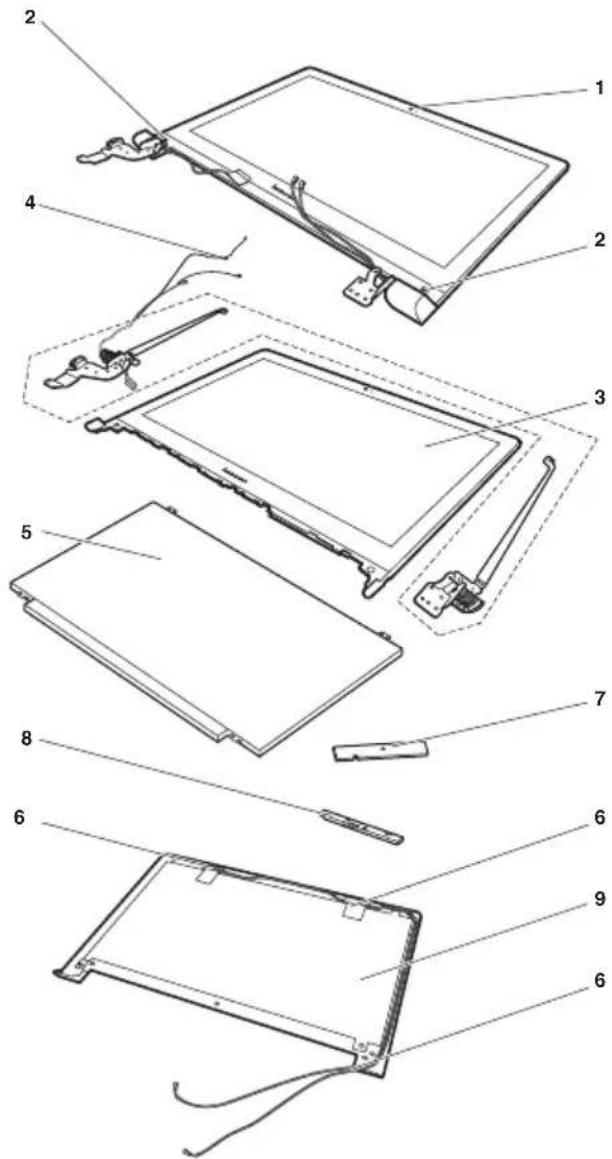
text_image
Exploded view diagram of a tablet device with numbered parts for identification14.0-in. HD TFT
Table 5. Parts list—14.0-in. HD TFT
| No. FRU FRU no. CRU | ID | |
| 1 DISPLAY LCD Module W Flex2-14 Grey (Flex2-14) | 5D10F76748 | N |
| 1 DISPLAY LCD Module W Flex2-14 Black FHD (Flex2-14) | 5D10F86070 | N |
| 1 DISPLAY LCD Module W Flex2-14 Grey FHD (Flex2-14) | 5D10F86069 | N |
| 1 DISPLAY LCD Module W Flex2-14D Black (Flex 2-14D) | 5D10G18360 | N |
| 2 RUBBER LCD Bezel Screw Pad W Flex2-14 (Flex 2-14/ Flex 2-14D) | 5R60F76763 | N |
| 3 BEZEL LCD W Flex2-14 White (Flex 2-14/Flex 2-14D) | 5B30F76779 | N |
| 3 BEZEL LCD W Flex2-14 Grey (Flex2-14) | 5B30F76772 | N |
| 3 BEZEL LCD W Flex2-14 Black (Flex 2-14/Flex 2-14D) | 5B30F76771 | N |
| 3 BEZEL LCD W Flex2-14 Red (Flex2-14) | 5B30F76783 | N |
| 3 BEZEL LCD W Flex2-14 Yellow (Flex 2-14/Flex 2-14D) | 5B30F76782 | N |
| 4 HINGE L+R W Flex2-14 W/LCD&Camera Cable (Flex 2-14/Flex 2-14D) | 5H50F76734 | N |
| 5 Panel 14.0 Edp HD TN 3.0 mm Slim LGD LP140WHU-TPBH HD AG S LED1 NB LCD (Flex2-14) | 18201582 N | |
| 5 Panel 14.0 Edp HD TN 3.0 mm Slim AUO B140XTN02.A HW0A HD AG S LED1 NB LCD (Flex2-14) | 18201154 N | |
| 5 Panel 14.0 Edp HD TN 3.0 mm Slim CMI N140BGE-EA3 C2 HD AG S LED1 NB LCD (Flex2-14) | 18201578 N | |
| 5 Panel 14.0 Edp FHD IPS AG 3.0mm Slim (Not used in Baytrial) LGD LP140WF3-SPL1 FHD AG S LED1 NB LCD (Flex2-14) | 18201637 N | |
| 5 Panel 14.0 Edp HD 3.0 mm Slim LGD LP140WHU-TPB3 HD AG S LED1 NB LCD (Flex2-14D) | 18201582 N | |
| 5 Panel 14.0 Edp HD 3.0 mm Slim AUO B140XTN02.A HW0A HD AG S LED1 NB LCD (Flex2-14D) | 18201154 N | |
| 5 Panel 14.0 Edp HD 3.0 mm Slim CMI N140BGE-EA3 C2 HD AG S LED1 NB LCD (Flex2-14D) | 18201578 N | |
| 6 ANTENNA WLAN W Flex2-14 MAIN/AUX (Flex 2-14/ Flex 2-14D) | 5A30F76752 | N |
| 7 CARDPOP Sensor Board W Flex2-14 (Flex2-14) | 5C50F76743 | N |
| 7 CARDPOP Sensor Board W Flex2-14D (Flex2-14D) | 5C50F78750 | N |
| 8 CAMERA W Flex2-14 0.3M W/1MIC (Flex 2-14/ Flex 2-14D) | 5C20F76774 | N |
| 8 CAMERA W Flex2-14 1M W/1MIC (Flex 2-14/Flex 2-14D) | 5C20F76777 | N |
| 8 CAMERA W Flex2-14 1M W/2MIC (Flex 2-14/Flex 2-14D) | 5C20F76778 | N |
| 9 COVER LCD W Flex2-14 White (Flex 2-14/Flex 2-14D) | 5CB0F76780 | N |
| 9 COVER LCD W Flex2-14 Black (Flex 2-14/Flex 2-14D) | 5CB0F76776 | N |
| 9 COVER LCD W Flex2-14 Grey (Flex2-14) | 5CB0F76786 | N |
| 9 COVER LCD W Flex2-14 Red (Flex2-14) | 5CB0F76785 | N |
| 9 COVER LCD W Flex2-14 Yellow (Flex 2-14/Flex 2-14D) | 5CB0F76781 | N |
15.6-in. HD TFT
Table 6. Parts list—15.6-in. HD TFT
| No. FRU FRU no. CRU | ID | |
| 1 DISPLAY LCD Module W Flex2-15 Black FHD (Flex 2-15) | 5D10F86071 | N |
| 1 DISPLAY LCD Module W Flex2-15D Black (Flex 2-15D) | 5D10G18359 | N |
| 2 RUBBER LCD Bezel Screw Pad W Flex2-15 (Flex 2-15/ Flex 2-15D) | 5R60F76742 | N |
| 3 BEZEL LCD W Flex2-15 Black (Flex 2-15/Flex 2-15D) | 5B30F76747 | N |
| 3 BEZEL LCD W Flex2-15 Red (Flex 2-15) | 5B30F76793 | N |
| 4 HINGE L+R W Flex2-15 W/LCD&Camera Cable (Flex 2-15/Flex 2-15D) | 5H50F76792 | N |
| 5 LCD Panel 15.6 Edp HD AG 3.0mm Slim LGD LP156WHU TPB2 HD AG S LED1 LCD | 18201590 N | |
| 5 LCD Panel 15.6 Edp HD AG 3.0mm Slim AUO B156XTN03.5 4A HD AG S LED1 LCD | 18201591 N | |
| 5 LCD Panel 15.6 Edp HD AG 3.0mm Slim CMI N156BGE-EA1 C2 HD AG S LED1 NB LCD | 18201589 N | |
| 5 LCD Panel15.6 Edp FHD IPS AG 3.0mm Slim(Not used in Baytrial) LGD LP156WF4-SPL1 FHD AG S LED1 NB LCD (Flex 2-15) | 18201638 | N |
| 6 ANTENNA WLAN W Flex2-15 MAIN/AUX (Flex 2-15/ Flex 2-15D) | 5A30F76795 | N |
| 7 CARDPOP Sensor Board W Flex2-15 (Flex 2-15) | 5C50F76765 | N |
| 7 CARDPOP Sensor Board W Flex2-15D (Flex 2-15D) | 5C50F78743 | N |
| 8 CAMERA W Flex2-14 0.3M W/1MIC (Flex 2-15/ Flex 2-15D) | 5C20F76774 | N |
| 8 CAMERA W Flex2-14 1M W/1MIC (Flex 2-15/Flex 2-15D) | 5C20F76777 | N |
| 8 CAMERA W Flex2-14 1M W/2MIC (Flex 2-15/Flex 2-15D) | 5C20F76778 | N |
| 9 COVER LCD W Flex2-15 Black (Flex 2-15/Flex 2-15D) | 5CB0F76749 | N |
| 9 COVER LCD W Flex2-15 Red (Flex 2-15) | 5CB0F76797 | N |
Keyboard
Table 7. Parts list—Keyboard
| Language P/N CRU | ID | |||
| keyboard Flex 2-14/ Flex 2-14D Normal (Black) | Chicony (black) | Indian 25214539 ** | ||
| Czechoslovakian 25214537 | ||||
| Bulgarian 25214538 | ||||
| International English 25214536 | ||||
| Swiss 25214535 | ||||
| Slovenian 25214534 | ||||
| Icelandic 25214533 | ||||
| Belgian 25214532 | ||||
| Four Nordic countries 25214531 | ||||
| Hungarian 25214530 | ||||
| Hebrew 25214529 | ||||
| Greek | 25214528 | |||
| Dutch | 25214527 | |||
| Japanese | 25214526 | |||
| Brazilian 25214525 | ||||
| Arabic | 25214524 | |||
| German 25214523 | ||||
| French | 25214522 | |||
| Russian | 25214521 | |||
| Traditional Chinese | 25214520 | |||
| Korean | 25214519 | |||
| Canadian English&French | 25214518 | |||
| Latin | 25214517 | |||
| Portuguese | 25214516 | |||
| Thai | 25214515 | |||
| Turkish | 25214514 | |||
| Spanish | 25214513 | |||
| Italian | 25214512 | |||
| U.K. English | 25214511 | |||
| English 25214510 | ||||
| Sunrex ( Black) | Indian 25214569 | |||
| Czechoslovakian 25214567 | ||||
| Bulgarian 25214568 | ||||
| International English 25214566 | ||||
| Swiss 25214565 | ||||
| Slovenian 25214564 | ||||
| Icelandic 25214563 | ||||
| Belgian 25214562 | ||||
| Four Nordic countries 25214561 | ||||
| Hungarian 25214560 | ||||
| Hebrew 25214559 | ||||
| Greek | 25214558 | |||
| Dutch | 25214557 | |||
| Brazilian 25214555 | ||||
| keyboard Flex2-14/ Flex 2-14D Normal (Black) (continued) | Sunrex (Black) (continued) | Arabic 25214554 ** | ||
| German 25214553 | ||||
| French 25214552 | ||||
| Russian 25214551 | ||||
| Traditional Chinese 25214550 | ||||
| Korean 25214549 | ||||
| Canadian English&French 25214548 | ||||
| Latin 25214547 | ||||
| Portuguese 25214546 | ||||
| Thai 25214545 | ||||
| Turkish 25214544 | ||||
| Spanish 25214543 | ||||
| Italian 25214542 | ||||
| U.K. English | 25214541 | |||
| English | 25214540 | |||
| Liteon (Black) | Indian | 25215219 | ||
| Bulgarian | 25215218 | |||
| Czechoslovakian | 25215217 | |||
| International English | 25215216 | |||
| Swiss | 25215215 | |||
| Slovenian | 25215214 | |||
| Icelandic | 25215213 | |||
| Belgian | 25215212 | |||
| Four Nordic countries | 25215211 | |||
| Hungarian | 25215210 | |||
| Hebrew 25215209 | ||||
| Greek | 25215208 | |||
| Dutch | 25215207 | |||
| Japanese | 25215206 | |||
| Brazilian | 25215205 | |||
| Arabic 25215204 | ||||
| German 25215203 | ||||
| French 25215202 | ||||
| Russian 25215201 | ||||
| Traditional Chinese 25215200 | ||||
| Korean 25215199 | ||||
| Canadian English&French 25215198 | ||||
| Latin 25215197 | ||||
| Portuguese 25215196 | ||||
| Thai 25215195 | ||||
| Turkish 25215194 | ||||
| Spanish 25215193 | ||||
| Italian 25215192 | ||||
| U.K. English | 25215191 | |||
| English | 25215190 | |||
| keyboard Flex 2-14/ Flex 2-14D Normal (Silver) | Chicony (Silver) | Indian 25215129 ** | ||
| Bulgarian 25215128 | ||||
| Czechoslovakian 25215127 | ||||
| International English 25215126 | ||||
| Swiss 25215125 | ||||
| Slovenian 25215124 | ||||
| Icelandic 25215123 | ||||
| Belgian 25215122 | ||||
| Four Nordic countries 25215121 | ||||
| Hungarian 25215120 | ||||
| Hebrew 25215119 | ||||
| Greek | 25215118 | |||
| Dutch | 25215117 | |||
| Japanese | 25215116 | |||
| Brazilian 25215115 | ||||
| Arabic | 25215114 | |||
| German 25215113 | ||||
| French | 25215112 | |||
| Russian | 25215111 | |||
| Traditional Chinese | 25215110 | |||
| Korean | 25215109 | |||
| Canadian English&French | 25215108 | |||
| Latin | 25215107 | |||
| Portuguese | 25215106 | |||
| Thai | 25215105 | |||
| Turkish | 25215104 | |||
| Spanish | 25215103 | |||
| Italian | 25215102 | |||
| U.K. English | 25215101 | |||
| English 25215100 | ||||
| Sunrex (Silver) | Indian 25215159 | |||
| Bulgarian 25215158 | ||||
| Czechoslovakian 25215157 | ||||
| International English 25215156 | ||||
| Swiss 25215155 | ||||
| Slovenian 25215154 | ||||
| Icelandic 25215153 | ||||
| Belgian 25215152 | ||||
| Four Nordic countries 25215151 | ||||
| Hungarian 25215150 | ||||
| Hebrew 25215149 | ||||
| Greek | 25215148 | |||
| Dutch | 25215147 | |||
| Brazilian 25215145 | ||||
| keyboard Flex 2-14/ Flex 2-14D Normal (Silver) (continued) | Sunrex (Silver) (continued) | Arabic 25215144 ** | ||
| German 25215143 | ||||
| French 25215142 | ||||
| Russian 25215141 | ||||
| Traditional Chinese 25215140 | ||||
| Korean 25215139 | ||||
| Canadian English&French 25215138 | ||||
| Latin 25215137 | ||||
| Portuguese 25215136 | ||||
| Thai 25215135 | ||||
| Turkish 25215134 | ||||
| Spanish 25215133 | ||||
| Italian | 25215132 | |||
| U.K. English | 25215131 | |||
| English | 25215130 | |||
| Liteon (Silver) | Indian | 25215189 | ||
| Bulgarian | 25215188 | |||
| Czechoslovakian | 25215187 | |||
| International English | 25215186 | |||
| Swiss | 25215185 | |||
| Slovenian | 25215184 | |||
| Icelandic | 25215183 | |||
| Belgian | 25215182 | |||
| Four Nordic countries | 25215181 | |||
| Hungarian | 25215180 | |||
| Hebrew 25215179 | ||||
| Greek | 25215178 | |||
| Dutch | 25215177 | |||
| Japanese | 25215176 | |||
| Brazilian | 25215175 | |||
| Arabic 25215174 | ||||
| German 25215173 | ||||
| French 25215172 | ||||
| Russian 25215171 | ||||
| Traditional Chinese 25215170 | ||||
| Korean 25215169 | ||||
| Canadian English&French 25215168 | ||||
| Latin 25215167 | ||||
| Portuguese 25215166 | ||||
| Thai 25215165 | ||||
| Turkish 25215164 | ||||
| Spanish 25215163 | ||||
| Italian | 25215162 | |||
| U.K. English | 25215161 | |||
| English | 25215160 | |||
| keyboard Flex 2-14 Backlight (Silver) | Chicony Silver | English 25215587 ** | ||
| English (USA) 25215588 | ||||
| U.K. English 25215589 | ||||
| Italian 25215590 | ||||
| Spanish 25215591 | ||||
| Turkish 25215592 | ||||
| Thai 25215593 | ||||
| Portuguese 25215594 | ||||
| Latin 25215595 | ||||
| Canadian English&French 25215596 | ||||
| Korean 25215597 | ||||
| Traditional Chinese | 25215598 | |||
| Russian 25215599 | ||||
| French | 25215600 | |||
| German | 25215601 | |||
| Arabic | 25215602 | |||
| Brazilian | 25215603 | |||
| Japanese | 25215604 | |||
| Dutch | 25215605 | |||
| Greek | 25215606 | |||
| Hebrew | 25215607 | |||
| Hungarian | 25215608 | |||
| Four Nordic countries | 25215609 | |||
| Belgian 25215610 | ||||
| Icelandic | 25215611 | |||
| Slovenian | 25215612 | |||
| Swiss | 25215613 | |||
| International English | 25215614 | |||
| Czechoslovakian | 25215615 | |||
| Bulgarian | 25215616 | |||
| Indian | 25215617 | |||
| Liteon Silver | English 25215618 | |||
| English (USA) 25215619 | ||||
| U.K. English 25215620 | ||||
| Italian 25215621 | ||||
| Spanish 25215622 | ||||
| Turkish 25215623 | ||||
| Thai 25215624 | ||||
| Portuguese 25215625 | ||||
| Latin 25215626 | ||||
| Canadian English&French 25215627 | ||||
| Korean 25215628 | ||||
| Traditional Chinese | 25215629 | |||
| Russian 25215630 | ||||
| French | 25215631 | |||
| German | 25215632 | |||
| keyboard Flex 2-14 Backlight (Silver) | Liteon Silver (continued) | Arabic 25215633 ** | ||
| Brazilian 25215634 | ||||
| Japanese 25215635 | ||||
| Dutch 25215636 | ||||
| Greek 25215637 | ||||
| Hebrew 25215638 | ||||
| Hungarian 25215639 | ||||
| Four Nordic countries 25215640 | ||||
| Belgian 25215641 | ||||
| Icelandic 25215642 | ||||
| Slovenian 25215643 | ||||
| Swiss 25215644 | ||||
| International English | 25215645 | |||
| Czechoslovakian | 25215646 | |||
| Bulgarian | 25215647 | |||
| Indian | 25215648 | |||
| keyboard Flex 2-14 Backlight (Black) | Chicony Black | English 25214816 | ||
| English (USA) | 25214817 | |||
| U.K. English | 25214818 | |||
| Italian | 25214819 | |||
| Spanish | 25214820 | |||
| Turkish | 25214821 | |||
| Thai | 25214822 | |||
| Portuguese | 25214823 | |||
| Latin | 25214824 | |||
| Canadian English&French | 25214825 | |||
| Korean | 25214826 | |||
| Traditional Chinese | 25214827 | |||
| Russian | 25214828 | |||
| French | 25214829 | |||
| German 25214830 | ||||
| Arabic 25214831 | ||||
| Brazilian 25214832 | ||||
| Japanese 25214833 | ||||
| Dutch 25214834 | ||||
| Greek 25214835 | ||||
| Hebrew 25214836 | ||||
| Hungarian 25214837 | ||||
| Four Nordic countries 25214838 | ||||
| Belgian 25214839 | ||||
| Icelandic 25214840 | ||||
| Slovenian 25214841 | ||||
| Swiss 25214842 | ||||
| International English | 25214843 | |||
| Czechoslovakian | 25214844 | |||
| Bulgarian | 25214845 | |||
| Indian | 25214846 | |||
| keyboard Flex 2-14 Backlight (Black) (continued) | Liteon Black | English 25215649 ** | ||
| English(USA) 25215650 | ||||
| U.K. English 25215651 | ||||
| Italian 25215652 | ||||
| Spanish 25215653 | ||||
| Turkish 25215654 | ||||
| Thai 25215655 | ||||
| Portuguese 25215656 | ||||
| Latin 25215657 | ||||
| Canadian English&French 25215658 | ||||
| Korean 25215659 | ||||
| Traditional Chinese | 25215660 | |||
| Russian 25215661 | ||||
| French | 25215662 | |||
| German | 25215663 | |||
| Arabic | 25215664 | |||
| Brazilian | 25215665 | |||
| Japanese | 25215666 | |||
| Dutch | 25215667 | |||
| Greek | 25215668 | |||
| Hebrew | 25215669 | |||
| Hungarian | 25215670 | |||
| Four Nordic countries | 25215671 | |||
| Belgian 25215672 | ||||
| Icelandic | 25215673 | |||
| Slovenian | 25215674 | |||
| Swiss | 25215675 | |||
| International English | 25215676 | |||
| Czechoslovakian | 25215677 | |||
| Bulgarian | 25215678 | |||
| Indian | 25215679 | |||
| keyboard Flex2-15/ Flex 2-15D Normal (Black) | Chicony Black | English 25214725 ** | ||
| U.K. English 25214726 | ||||
| Italian 25214727 | ||||
| Spanish 25214728 | ||||
| Turkish 25214729 | ||||
| Thai 25214730 | ||||
| Portuguese 25214731 | ||||
| Latin 25214732 | ||||
| Canadian English&French 25214733 | ||||
| Korean 25214734 | ||||
| Traditional Chinese 25214735 | ||||
| Russian 25214736 | ||||
| French | 25214737 | |||
| German | 25214738 | |||
| Arabic | 25214739 | |||
| Brazilian | 25214740 | |||
| Dutch | 25214742 | |||
| Greek | 25214743 | |||
| Hebrew | 25214744 | |||
| Hungarian | 25214745 | |||
| Four Nordic countries | 25214746 | |||
| Belgian 25214747 | ||||
| Icelandic | 25214748 | |||
| Slovenian | 25214749 | |||
| Swiss | 25214750 | |||
| International English | 25214751 | |||
| Czechoslovakian | 25214752 | |||
| Bulgarian | 25214753 | |||
| Indian | 25214754 | |||
| Sunrex Black | English 25214755 | |||
| U.K. English 25214756 | ||||
| Italian 25214757 | ||||
| Spanish 25214758 | ||||
| Turkish 25214759 | ||||
| Thai 25214760 | ||||
| Portuguese 25214761 | ||||
| Latin 25214762 | ||||
| Canadian English&French 25214763 | ||||
| Korean 25214764 | ||||
| Traditional Chinese 25214765 | ||||
| Russian 25214766 | ||||
| French | 25214767 | |||
| German | 25214768 | |||
| keyboard Flex2-15/ Flex 2-15D Normal (Black) (continued) | Sunrex Black (continued) | Arabic 25214769 ** | ||
| Brazilian 25214770 | ||||
| Japanese 25214771 | ||||
| Dutch 25214772 | ||||
| Greek 25214773 | ||||
| Hebrew 25214774 | ||||
| Hungarian 25214775 | ||||
| Four Nordic countries 25214776 | ||||
| Belgian 25214777 | ||||
| Icelandic 25214778 | ||||
| Slovenian 25214779 | ||||
| Swiss 25214780 | ||||
| International English | 25214781 | |||
| Czechoslovakian | 25214782 | |||
| Bulgarian | 25214783 | |||
| Indian | 25214784 | |||
| Darfon Black | English 25214785 | |||
| U.K. English | 25214786 | |||
| Italian | 25214787 | |||
| Spanish | 25214788 | |||
| Turkish | 25214789 | |||
| Thai | 25214790 | |||
| Portuguese | 25214791 | |||
| Latin | 25214792 | |||
| Canadian English&French | 25214793 | |||
| Korean | 25214794 | |||
| Traditional Chinese | 25214795 | |||
| Russian | 25214796 | |||
| French | 25214797 | |||
| German 25214798 | ||||
| Arabic 25214799 | ||||
| Brazilian 25214800 | ||||
| Japanese 25214801 | ||||
| Dutch 25214802 | ||||
| Greek 25214803 | ||||
| Hebrew 25214804 | ||||
| Hungarian 25214805 | ||||
| Four Nordic countries 25214806 | ||||
| Belgian 25214807 | ||||
| Icelandic 25214808 | ||||
| Slovenian 25214809 | ||||
| Swiss 25214810 | ||||
| International English | 25214811 | |||
| Czechoslovakian | 25214812 | |||
| Bulgarian | 25214813 | |||
| Indian | 25214814 | |||
| keyboard Flex2-15 Backlit Black | Sunrex Black | English 25214632 ** | ||
| English(USA) 25214633 | ||||
| U.K. English 25214634 | ||||
| Italian 25214635 | ||||
| Spanish 25214636 | ||||
| Turkish 25214637 | ||||
| Thai 25214638 | ||||
| Portuguese 25214639 | ||||
| Latin 25214640 | ||||
| Canadian English&French 25214641 | ||||
| Korean 25214642 | ||||
| Traditional Chinese | 25214643 | |||
| Russian 25214644 | ||||
| French | 25214645 | |||
| German | 25214646 | |||
| Arabic | 25214647 | |||
| Brazilian | 25214648 | |||
| Japanese | 25214649 | |||
| Dutch | 25214650 | |||
| Greek | 25214651 | |||
| Hebrew | 25214652 | |||
| Hungarian | 25214653 | |||
| Four Nordic countries | 25214654 | |||
| Belgian 25214655 | ||||
| Icelandic | 25214656 | |||
| Slovenian | 25214657 | |||
| Swiss | 25214658 | |||
| International English | 25214659 | |||
| Czechoslovakian | 25214660 | |||
| Bulgarian | 25214661 | |||
| Indian | 25214662 | |||
| keyboard Flex2-15 Backlit Black (continued) | Darfon Black | English 25214663 ** | ||
| English(USA) 25214664 | ||||
| U.K. English 25214665 | ||||
| Italian 25214666 | ||||
| Spanish 25214667 | ||||
| Turkish 25214668 | ||||
| Thai 25214669 | ||||
| Portuguese 25214670 | ||||
| Latin 25214671 | ||||
| Canadian English&French 25214672 | ||||
| Korean 25214673 | ||||
| Traditional Chinese | 25214674 | |||
| Russian 25214675 | ||||
| French | 25214676 | |||
| German | 25214677 | |||
| Arabic | 25214678 | |||
| Brazilian | 25214679 | |||
| Japanese | 25214680 | |||
| Dutch | 25214681 | |||
| Greek | 25214682 | |||
| Hebrew | 25214683 | |||
| Hungarian | 25214684 | |||
| Four Nordic countries | 25214685 | |||
| Belgian 25214686 | ||||
| Icelandic | 25214687 | |||
| Slovenian | 25214688 | |||
| Swiss | 25214689 | |||
| International English | 25214690 | |||
| Czechoslovakian | 25214691 | |||
| Bulgarian | 25214692 | |||
| Indian | 25214693 | |||
Miscellaneous parts
Table 8. Parts list—Miscellaneous parts
| FRU P/N CRU | ID | |
| System miscellaneous parts: | N | |
| (a) BRACKET HDD W Flex2-14 (Flex 2-14/Flex 2-14D) | 5B40F76744 | |
| (a) BRACKET HDD W Flex2-15 (Flex 2-15/Flex 2-15D) | 5B40F76773 | |
| (b) BRACKET ODD W Flex2-15 (Flex 2-15/Flex 2-15D) | 5B40F76757 | |
| (c) BEZEL ODD W Flex2-15 Red (Flex 2-15) | 5B30F76789 | |
| (c) BEZEL ODD W Flex2-15 Black (Flex 2-15/Flex 2-15D) | 5B30F76745 | |
| Cable miscellaneous parts: | N | |
| (d) CABLE Power W Flex2-15 (Flex 2-15/Flex 2-15D) | 5C10F76788 | |
| (e) CABLE TouchPad W Flex2-14 (Flex 2-14/Flex 2-14D) | 5C10F76775 | |
| (e) CABLE TouchPad W Flex2-15 (Flex 2-15/Flex 2-15D) | 5C10F76787 | |
| (f) CABLE IO Board W Flex2-14 (Flex 2-14/Flex 2-14D) | 5C10F76740 | |
| (f) CABLE IO Board W Flex2-15 (Flex 2-15/Flex 2-15D) | 5C10F76767 | |
| Note:Italicized letters in parentheses are references to the exploded view in “Overall” on page 71. | ||
AC adapters
Table 9. Parts list—3-pin AC adapters
| FRU P/N CRU | ID | |
| 45W(3pin) Delta ADLX45NDC3A 20V2.25A adapter Delta 36200602 * | ||
| 45W(3pin) Liteon ADLX45NLC3A 20V2.25A adapter Liteon 36200606 * | ||
| 45W(3pin) Chicony ADLX45NCC3A 20V2.25A adapter Chicony | 36200610 * | |
| 65W(3pin) Delta ADLX65NDC3A 20V3.25A adapter 36200249 * | ||
| 65W(3pin) Liteon ADLX65NLC3A 20V3.25A adapter Liteon 36200607 * | ||
| 65W(3pin) Chicony ADLX65NCC3A 20V3.25A adapter Chicony | 36200611 * |
Screws
Table 10. Parts list --screws
| FRU P/N CRU | ID | |
| SCREW Pack W Flex2-14 5S10F76732 N | ||
| SCREW Screw pack W Flex2-14D 5S10F78742 N | ||
| SCREW Screw pack W Flex2-15 5S10F76739 N | ||
| SCREW Screw pack W Flex2-15D 5S10F78749 N |
Power cords
A Lenovo power cord for a specific country or region is usually available only in that country or region:
Table 11. Parts list—3-pin power cords
| Region P/N CRU | ID | |
| CCC• LINETEK PC323+RVV300/300+LS15 1m | 145000600 * | |
| Argentina• LINETEK LS15+H03VV-F+LP39 1m | 145000599 | |
| Denmark• LINETEK LS15+H03VV-F+LP-38 1m | 145000598 | |
| Switzerland• LINETEK LS15+H03VV-F+LP-37 1m | 145000597 | |
| Brazil• LINETEK LS15 H03VV-F LP26A 1m | 145000596 | |
| Israel• LINETEK LS15+H03VV-F+LP-41 1m | 145000595 | |
| UL• LINETEK LP-30B + SPT-2 + LS15 1m | 145000594 | |
| UK• LINETEK LP-61L+ H03VV-F+ LS15 1m | 145000593 | |
| Indian• LINETEK PE-361+ H05VV-F+ LS15 1m | 145000592 | |
| Italy• LINETEK LS15+H03VV-F+PE-336 1m | 145000591 | |
| Korea• LINETEK LS15+H05VV-F+LP-E04A 1m | 145000590 | |
| Australia• LINETEK LS15+H03VV-F+LP-23A 1m | 145000589 | |
| Taiwan• LINETEK LS15+VCTF+LP-53 1m | 145000588 | |
| Japan• LINETEK LS15+VCTF+LP-54 1m | 145000587 | |
| Africa• LINETEK LS15+H03VV-F+PE-364 1m | 145000586 | |
| CE• LINETEK LP-34+H03VV-F + LS15 1m | 145000585 | |
| CCC• Longwell LSG-31+RVV300/300+LS-18 1m | 145000568 | |
| Argentina• Longwell LP-24+H03VV-F+LS-18 1m | 145000567 | |
| Denmark• Longwell LP-40+H03VV-F+LS-18 1m | 145000566 | |
| Switzerland• Longwell LP-37+H03VV-F+LS-18 1m | 145000565 | |
| BrazilLongwell LP-46+H03VV-F+LS-18 1m | 145000564 * | |
| IsraelLongwell LP-41+H03VV-F+LS-18 1m | 145000563 | |
| ULLongwell LP-30B+SPT-2 18AWG+LS-18 1m | 145000562 | |
| UKLongwell LP-61L+H03VV-F+LS-18 1m | 145000561 | |
| IndianLongwell LP-67+BIS+LS-18 1m | 145000560 | |
| ItalyLongwell LP-22+H03VV-F+LS-18 1m | 145000559 | |
| KoreaLongwell LP-486+KTLH03VV-F+LS-5 1m | 145000558 | |
| AustraliaLongwell LP-23A+LFC-3R+LS-18 1m | 145000557 | |
| TaiwanLongwell LP-71+VCTF+LS-33 1m | 145000556 | |
| JapanLongwell LP-54+VCTF+LS-18 1m | 145000555 | |
| AfricaLongwell LP-39+H03VV-F+LS-18 1m | 145000554 | |
| CELongwell LP-34A+H03VV-F+LS-18 1m | 145000553 | |
| CCCVOLEX GB10S3+RVV 300/500+VAC5S 1m | 145000538 | |
| ULVolex US15S3+SPT-2 +VAC5S 1m | 145000537 | |
| ItalyVOLEX IT10S3+HO3VV-F+VAC5S 1m | 145000535 | |
| DenmarkVOLEX MP233D+H03VV-F+VAC5S 1m | 145000534 | |
| KoreaVOLEX M2511+KETI IEC+VAC5S 1m | 145000533 | |
| AustraliaVOLEX AU10S3+H03VV-F+VAC5S 1m | 145000532 | |
| TaiwanVOLEX TW15CS3+VCTF+VAC5S 1m | 145000531 | |
| JapanVOLEX VAC5S+VCTF+M755 1m | 145000530 | |
| ArgentinaVOLEX VA2073+H03VV-F+VAC5S 1m | 145000528 | |
| BrazilVOLEX CH10S3+H03VV-F+VAC5S 1m | 145000527 | * |
| IsraelVOLEX SI16S3+H03VV-F+VAC5S 1m | 145000526 | |
| CEVOLEX M2511+H03VV-F+VAC5S 1m | 145000525 | |
| SwitzerlandVOLEX MP232+H03VV-F+VAC5S 1m | 145000524 | |
| UKVOLEX MP5004+H03VV-F+VAC5S 1m | 145000605 | |
| UKlux 0031+H03VV-F 0.75/3C+0011 1m | 145500000 * | |
| CElux 0033+H03VV-F 0.75/3C+0011 1m | 145500001 * | |
| ULlux 0014+SPT-2 60°C 18/3C+0016 1m | 145500002 * | |
| CCClux 0036+RVV 300/300 0.75/3C+0002 1m | 145500003 * | |
| Indianlux 0046+IS694 0.75/3C+0011 1m | 145500004 * | |
| Japanlux 0018(E)+VCTF 0.75/3C+0021 1m | 145500005 * | |
| Australialux 0038+H03VV-F 0.75/3C+0011 1m | 145500006 * | |
| Taiwanlux 0019+VCTF 0.75/3C+0021 1m | 145500007 * | |
| Korealux 0033+H03VV-F 0.75/3C+0011 1m | 145500008 * | |
| Italylux 0029+H03VV-F 0.75/3C+0011 1m | 145500009 * | |
| Africalux 0044+H03VV-F 0.75/3C+0011 1m | 145500010 * | |
| Brazillux 0034+H03VV-F 0.75/3C+0011 1m | 145500011 * | |
| Israellux 0041+H03VV-F 0.75/3C+0011 1m | 145500012 * | |
| Switzerlandlux 0027+H03VV-F 0.75/3C+0011 1m | 145500013 * | |
| Denmarklux 0048+H03VV-F 0.75/3C+0011 1m | 145500014 * | |
| Argentinalux 0040+H03VV-F 0.75/3C+0011 1m | 145500015 * |
Notices
Lenovo may not offer the products, services, or features discussed in this document in all countries. Consult your local Lenovo representative for information on the products and services currently available in your area. Any reference to a Lenovo product, program, or service is not intended to state or imply that only that Lenovo product, program, or service may be used. Any functionally equivalent product, program, or service that does not infringe any Lenovo intellectual property right may be used instead. However, it is the user's responsibility to evaluate and verify the operation of any other product, program, or service.
Lenovo may have patents or pending patent applications covering subject matter described in this document. The furnishing of this document does not give you any license to these patents.
LENOVO GROUP LTD. PROVIDES THIS PUBLICATION "AS IS" WITHOUT WARRANTY OF ANY KIND, EITHER EXPRESS OR IMPLIED, INCLUDING, BUT NOT LIMITED TO, THE IMPLIED WARRANTIES OF NON-INFRINGEMENT, MERCHANTABILITY OR FITNESS FOR A PARTICULAR PURPOSE. Some jurisdictions do not allow disclaimer of express or implied warranties in certain transactions, therefore, this statement may not apply to you.
This information could include technical inaccuracies or typographical errors. Changes are periodically made to the information herein; these changes will be incorporated in new editions of the publication. Lenovo may make improvements and/or changes in the product(s) and/or the program(s) described in this publication at any time without notice.
The products described in this document are not intended for use in implantation or other life support applications where malfunction may result in injury or death to persons. The information contained in this document does not affect or change Lenovo product specifications or warranties. Nothing in this document shall operate as an express or implied license or indemnity under the intellectual property rights of Lenovo or third parties. All information contained in this document was obtained in specific environments and is presented as an illustration. The result obtained in other operating environments may vary.
Lenovo may use or distribute any of the information you supply in any way it believes appropriate without incurring any obligation to you.
Any references in this publication to non-Lenovo Web sites are provided for convenience only and do not in any manner serve as an endorsement of those Web sites. The materials at those Web sites are not part of the materials for this Lenovo product, and use of those Web sites is at your own risk.
Any performance data contained herein was determined in a controlled environment. Therefore, the result obtained in other operating environments may vary significantly. Some measurements may have been made on development-level systems and there is no guarantee that these measurements will be the same on generally available systems. Furthermore, some measurements may have been estimated through extrapolation. Actual results may vary. Users of this document should verify the applicable data for their specific environment.
Trademarks
The following terms are trademarks or registered trademarks of Lenovo in the United States, other countries, or both.
Lenovo
OneKey
Microsoft and Windows are trademarks of Microsoft Corporation in the United States, other countries, or both.
Other company, products, or service names may be trademarks or service marks of others.