
XH G1 - Camcorder CANON - Free user manual and instructions
Find the device manual for free XH G1 CANON in PDF.


| Product Type | Professional HDV/DV Camcorder |
| Model | Canon XH G1 |
| Image Sensor | 3x 1/3-inch CCD, approx. 1.67 megapixels each |
| Lens | 20x optical zoom, f=4.5-90mm, F/1.6-3.5, 72mm filter diameter |
| Recording Media | MiniDV tape (HDV/DV), SD/SDHC/MMC card for still images |
| Video Recording Format | HDV 1080i, DV (SP/LP) |
| Audio Recording | HDV: MPEG-1 Audio Layer II 16-bit 48kHz; DV: PCM 16-bit 48kHz or 12-bit 32kHz |
| Viewfinder | 0.57-inch TFT color, approx. 269,000 pixels |
| LCD Screen | 2.8-inch widescreen TFT color, approx. 207,000 pixels |
| Power Supply | 7.4V DC (battery pack) or 100-240V AC via CA-920 Compact Power Adapter |
| Power Consumption | Approx. 7.1-7.3W (XH G1, HD mode, viewfinder/LCD normal) |
| Dimensions (WxHxD) | 163 x 189 x 350 mm (without grip belt) |
| Weight | Approx. 2,100 g (body only) |
| Image Stabilization | Optical shift (can be turned off) |
| Focus System | Autofocus (Normal/Instant) and manual focus with peaking/magnifying assist |
| White Balance | Auto, preset (indoor/outdoor), custom, color temperature setting |
| Minimum Illumination | 0.4 lux (60i/30F, manual mode, 1/4 shutter, F1.6, gain 18 dB) |
| Input/Output Terminals | HD/SD SDI (XH G1 only), GENLOCK, TIME CODE, COMPONENT OUT, HDV/DV (IEEE1394), A/V, MIC, XLR (2x), headphones, LANC |
| Operating Temperature | 0-40°C (32-104°F) |
| Cleaning and Maintenance | Clean body with soft dry cloth; video heads may require cleaning using DVM-CL cleaning cassette |
| Safety Precautions | Do not expose to rain/moisture; use recommended accessories; avoid magnetic/electric fields; unplug during lightning |
| Spare Parts and Repairability | Use only Canon-specified replacement parts; servicing by qualified personnel only |
Frequently Asked Questions - XH G1 CANON
User questions about XH G1 CANON
0 question about this device. Answer the ones you know or ask your own.
Ask a new question about this device
Download the instructions for your Camcorder in PDF format for free! Find your manual XH G1 - CANON and take your electronic device back in hand. On this page are published all the documents necessary for the use of your device. XH G1 by CANON.
USER MANUAL XH G1 CANON
natural_image
Line drawing of a Canon digital camera with lens and external frame (no text or symbols on body)Mini
DV
Digital Video
Cassette
HDV
HDV 1080i
WARNING:

TO REDUCE THE RISK OF FIRE OR ELECTRIC SHOCK, DO NOT EXPOSE THIS PRODUCT TO RAIN OR MOISTURE.
WARNING:

TO REDUCE THE RISK OF ELECTRIC SHOCK AND TO REDUCE ANNOYING INTERFERENCE, USE THE RECOMMENDED ACCESSORIES ONLY.
COPYRIGHT WARNING:
Unauthorized recording of copyrighted materials may infringe on the rights of copyright owners and be contrary to copyright laws.
Digital Video Camcorder, XH G1 A/XH A1 A Systems.
This device complies with Part 15 of the FCC Rules. Operation is subject to the following two conditions: (1) This device may not cause harmful interference, and (2) this device must accept any interference received, including interference that may cause undesired operation.
Note: This equipment has been tested and found to comply with the limits for class B digital device, pursuant to Part 15 of the FCC Rules. These limits are designed to provide reasonable protection against harmful interference in a residential installation. This equipment generates, uses and can radiate radio frequency energy and, if not installed and use in accordance with the instructions, may cause harmful interference to radio communications. However, there is no guarantee that interference will not occur in a particular installation. If this equipment does cause harmful interference to radio or television reception, which can be determined by turning the equipment off and on, the user is encouraged to try to correct the interference by one or more of the following measures:
- Reorient or relocate the receiving antenna.
- Increase the separation between the equipment and receiver.
- Connect the equipment into an outlet on a circuit different from that to which the receiver is connected.
- Consult the dealer or an experienced radio/TV technician for help.
Use of shielded cable is required to comply with class B limits in Subpart B of Part 15 of FCC Rules.
Do not make any changes or modifications to the equipment unless otherwise specified in the manual. If such changes or modifications should be made, you could be required to stop operation of the equipment. Canon U.S.A. Inc.
One Canon Plaza, Lake Success, NY 11042, U.S.A.
Tel No. (516)328-5600
CAUTION:
TO PREVENT ELECTRIC SHOCK, MATCH WIDE BLADE OF PLUG TO WIDE SLOT, FULLY INSERT.
Important Warning


CAUTION:
TO REDUCE THE RISK OF ELECTRIC SHOCK, DO NOT REMOVE COVER (OR BACK). NO USER-SERVICEABLE PARTS INSIDE. REFER SERVICING TO QUALIFIED SERVICE PERSONNEL.

The lightning flash with arrowhead symbol, within an equilateral triangle, is intended to alert the user to the presence of uninsulated “dangerous voltage” within the product’s enclosure, that may be of sufficient magnitude to constitute a risk of electric shock to persons.

The exclamation point, within an equilateral triangle, is intended to alert the user to the presence of important operating and maintenance (servicing) instructions in the literature accompanying the product.
In these safety instructions the word "product" refers to the Canon HD Video Camera Recorder XH G1 A/XH A1 A and all its accessories.
- Read Instructions — All the safety and operating instructions should be read before the product is operated.
- Retain Instructions — The safety and operating instructions should be retained for future reference.
- Heed Warnings — All warnings on the product and in the operating instructions should be adhered to.
- Follow Instructions — All operating and maintenance instructions should be followed.
- Cleaning — Unplug this product from the wall outlet before cleaning. Do not use liquid or aerosol cleaners. The product should be cleaned only as recommended in this manual.
- Accessories — Do not use accessories not recommended in this manual as they may be hazardous.
- Avoid magnetic or electric fields — Do not use the camera close to TV transmitters, portable communication devices or other sources of electric or magnetic radiation. They may cause picture interference, or permanently damage the camera.
- Water and Moisture — Hazard of electric shock — Do not use this product near water or in rainy/moist situations.
- Placing or Moving — Do not place on an unstable cart, stand, tripod, bracket or table. The product may fall, causing serious injury to a child or adult, and serious damage to the product.
A product and cart combination should be moved with care. Quick stops, excessive force, and uneven surfaces may cause the product and cart combination to overturn.

- Power Sources — The CA-920 Compact Power Adapter should be operated only from the type of power source indicated on the marking label. If you are not sure of the type of power supply to your home, consult your product dealer or local power company. Regarding other power sources such as battery power, refer to instructions in this manual.
-
Polarization — The CA-920 Compact Power Adapter is equipped with a polarized 2-prong plug (a plug having one blade wider than the other). The 2-prong polarized plug will fit into the power outlet only one way. This is a safety feature. If you are unable to insert the plug fully into the outlet, try reversing the plug. If the plug still fails to fit, contact your electrician to replace your obsolete outlet. Do not defeat the safety purpose of the polarized plug.
-
Power Cord Protection — Power cords should be routed so that they are not likely to be walked on or pinched by items placed upon or against them. Pay particular attention to plugs and the point from which the cords exit the product.
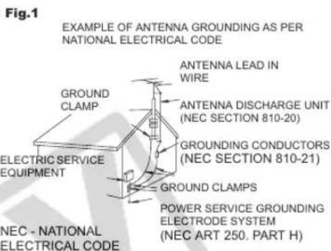
- Outdoor Antenna Grounding — If an outside antenna is connected to the product, be sure the antenna is grounded so as to provide some protection against voltage surges and built-up static charges. Section 810 of the National Electrical Code, ANSI / NFPA No. 70—1984, provides information with respect to proper grounding of the mast and supporting structure, grounding of the lead-in wire to an antenna discharge unit, size of grounding conductors, location of antenna discharge unit, connection to grounding electrodes, and requirements for the grounding electrode. See figure 1.
text_image
Fig.1 EXAMPLE OF ANTENNA GROUNDING AS PER NATIONAL ELECTRICAL CODE GROUNDS CLAMP ELECTRIC SERVICE EQUIPMENT ANTENNA LEAD IN WIRE ANTENNA DISCHARGE UNIT (NEC SECTION 810-20) GROUNDING CONDUCTORS (NEC SECTION 810-21) GROUND CLAMPS POWER SERVICE GROUNDING ELECTRODE SYSTEM (NEC ART 250. PART H)- Lightning — For added protection of this product during a lightning storm, or when it is left unattended and unused for long periods of time, disconnect it from the wall outlet and disconnect the antenna. This will prevent damage to the product due to lightning and power-line surges.
- Power Lines — An outside antenna system should not be located in the vicinity of overhead power lines or other electric light or power circuits, or where it can fall into such power lines or circuits. When installing an outside antenna system, extreme care should be taken to keep from touching such power lines or circuits as contact with them might be fatal.
- Overloading — Do not overload wall outlets and extension cords as this can result in a risk of fire or electric shock.
- Objects and Liquid Entry — Never push objects of any kind into this product through openings as they may touch dangerous voltage points or short out parts that could result in a fire or electric shock. Be careful not to spill liquid of any kind onto the product.
-
Servicing — Do not attempt to service this product yourself as opening or removing covers may expose you to dangerous voltage or other hazards. Refer all servicing to qualified service personnel.
-
Damage Requiring Service — Disconnect this product from the wall outlet and all power sources including battery, and refer servicing to qualified service personnel under the following conditions:
a. When the power-supply cord or plug is damaged.
b. If any liquid has been spilled onto, or objects have fallen into, the product.
c. If the product has been exposed to rain or water.
d. If the product does not operate normally even if you follow the operating instructions. Adjust only those controls that are covered by the operation instructions. Improper adjustment of other controls may result in damage and will often require extensive work by a qualified technician to restore the product to its normal operation.
e. If the product has been dropped or the cabinet has been damaged.
f. When the product exhibits a distinct change in performance. This indicates a need for service.
- Replacement Parts — When replacement parts are required, be sure the service technician has used replacement parts that are specified by Canon or that have the same characteristics as the original part. Unauthorized substitutions may result in fire, electric shock or other hazards.
- Safety Check — Upon completion of any service or repairs to this product, ask the service technician to perform safety checks to determine that the product is in safe operating order.
When replacement of power supply is required, please return it to the responsible nearest Canon Service Center and please replace it with the same type number CA-920.
The Adapter can be used with a power supply between 100 and 240 V AC. Contact your Canon dealer for information about plug adapter for overseas use.
Thank you for purchasing the Canon XH G1/XH A1. Please read this manual carefully before you use the camcorder and retain it for future reference. Should your camcorder fail to operate correctly, refer to the Troubleshooting table (152).
Conventions Used in this Manual
○ Precautions related to the camcorder operation.
○ Additional topics that complement the basic operating procedures.
○ □: Reference page number.
- Capital letters are used to refer to buttons on the camcorder or the wireless controller.
- Brackets [] and capital letters are used to refer to menu options as they are displayed on screen. Menu options in boldface indicate the default setting.
○ Illustrations included in the manual show the XH G1.
- "Screen" refers to the LCD screen and the viewfinder screen.
- “Card” or “Memory card” refers to an SDHC memory card, an SD memory card or a MultiMedia Card (MMC).
○ Photographs included in the manual are simulated pictures taken with a still camera.
○ XHG1 : Option or feature that applies or is available only with this model.
Operating modes
The availability of the various functions depends on the operating mode as indicated in the bar.

text_image
A, CARD: Function can be used in this mode. A, CARD: Function cannot be used in this mode.Menu item shown at its default position
text_image
Setting the Time Zone, Date and Time Set the time zone, date and time when you first start using your currentive, or if this built-in rechargeable battery has completely discharged. Setting the Time Zone/Daylight Saving Time TAVE CARD MENU 1. Press the MENU button. 2. Turn the SELECT/SET dial to select [SYSTEM SETUP] and press the dial. 3. Select [TIME SET] and then select [ZONE/DST] and press the dial. The time zone setting appears. The default setting is New York. 4. Turn the SELECT/SET dial to select the setting option that represents your time zone and press the dial. To adjust for daylight saving time, select the time zone with how next to the area. Setting the Date and Time TAVE CARD MENU 1. time set(s) 2. time set(s) 3. time set(s) 4. time set(s)Trademark Acknowledgements
- Canon is a registered trademark of Canon Inc.
• MiniDV is a trademark.
• HDV and the HDV logo are trademarks of Sony Corporation and Victor Company of Japan, Ltd. (JVC). - is a trademark.
- Windows ^ is either a trademark or registered trademark of Microsoft Corporation in the United States and/or other countries.
- Other names and products not mentioned above may be trademarks or registered trademarks of their respective companies.
- ANY USE OF THIS PRODUCT OTHER THAN CONSUMER PERSONAL USE IN ANY MANNER THAT COMPLIES WITH THE MPEG-2 STANDARD FOR ENCODING VIDEO INFORMATION FOR PACKAGED MEDIA IS EXPRESSLY PROHIBITED WITHOUT A LICENSE UNDER APPLICABLE PATENTS IN THE MPEG-2 PATENT PORTFOLIO, WHICH LICENSE IS AVAILABLE FROM MPEG LA, L.L.C., 250 STEELE STREET, SUITE 300, DENVER, COLORADO 80206.
About the HD/HDV and SD/DV Specifications
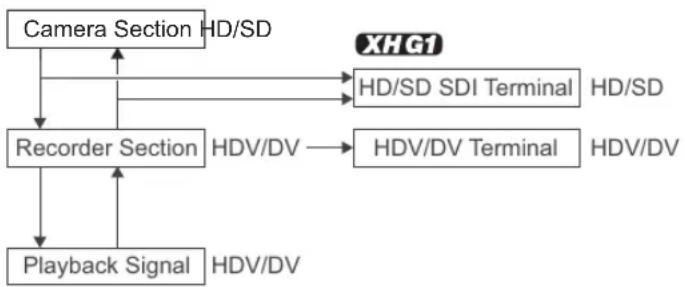
Throughout the manual we will distinguish between the video signal standards used by the camera section, and the recording standards used by the recorder section. The video signal can be set to HD (high definition) or SD (standard definition) specifications. The recording standard on the tape will be HDV or DV, respectively.
flowchart
graph TD
    A["Camera Section HD/SD"] --> B["Recorder Section"]
    B --> C["Playback Signal HDV/DV"]
    B --> D["HDV/DV"]
    D --> E["HDV/SD SDI Terminal HD/SD"]
    D --> F["HDV/DV Terminal HDV/DV"]
Introduction
Important Usage Instructions....2
Important Safety Instructions....3
About this Manual....5
Checking the Supplied Accessories....9
Components Guide....10
Preparations
Preparing the Power Supply....15
Preparing the Camcorder 18
Using the Wireless Controller 22
Loading/Removing a Cassette 23
Inserting/Removing a Memory Card....24
Changing Settings with the MENU Button....25
Setting the Time Zone, Date and Time....26
Recording
Recording 27
Selecting the Signal Standard and Aspect Ratio 31
Locating the End of the Last Scene 32
Zooming 33
Adjusting the Focus 35
Using the ND Filter 39
Selecting the Frame Rate....40
Setting the Time Code 42
XHG1 Synchronizing the Camcorder's Time Code 44
Setting the User Bit....46
Audio Recording 47
Image Stabilizer 51
Using the Programmed AE Modes 52
Recording in the Shutter-Priority (Tv) Mode 55
Recording in the Aperture-Priority (Av) Mode....56
Recording in the Manual Mode....57
Adjusting the Exposure....58
Using AE Shift 59
Adjusting the Gain 60
Setting the White Balance 62
Using the Zebra Pattern 64
Using the Color Correction 65
Using the Skin Detail Function 67
Using the Sky Detail 68
Using the Clear Scan Function....69
Using the Custom Keys....70
Recording Color Bars/Audio Reference Signal 73
Using the Digital Video Control....74
Other Camcorder Functions/Settings 75
Customization
Using the Custom Preset....76
Using the Customized Functions....83
Customizing the On-Screen Displays....90
Playback
Playing Back a Tape....95
Connecting to a Monitor/TV 97
SD Audio Output 100
Returning to a Pre-marked Position 101
Index Search 102
Date Search 103
Displaying the Data Code....104
Changing the Remote Sensor Mode 105
Editing
Recording an External Video Signal (Analog Line-In, HDV/DV In)....106
Converting Analog Signals into Digital Signals (Analog-Digital Converter) 108
Connecting to a Computer (IEEE1394)....109
Using a Memory Card
Selecting the Image Quality/Size....110
File Numbers 111
Recording Still Images on a Memory Card 112
Selecting the Drive Mode 115
Selecting the Metering Method....117
Using an Optional Flash 118
Reviewing a Still Image Right after Recording 119
Playing Back Still Images from a Memory Card 120
Erasing Images....122
Protecting Images....123
Initializing a Memory Card....124
Print Order Settings....125
Additional Information
Settings Retained at Power Off or STANDBY Mode 126
Menu Options and Default Settings....127
Screen Displays....142
List of Messages....145
Maintenance/Others 146
Troubleshooting....152
System Diagram....154
Optional Accessories....155
Specifications 158
Index 160
Checking the Supplied Accessories
CA-920 Compact Power Adapter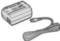 | DC-920 DC Coupler BP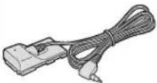 | -950G Battery Pack SDC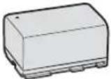 | C-16M SD Memory Card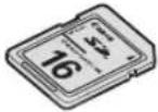 | WL-D5000 Wireless Controller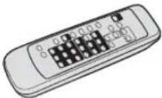 |
Two AA (R6) Batteries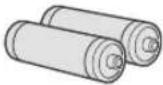 | Lens Hood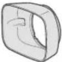 | Lens Cap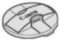 | SS-1100 Shoulder Strap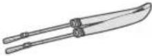 | STV-290N Stereo Video Cable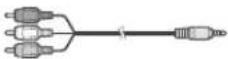 |
DTC-1000 Component Video Cable
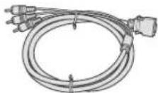
The serial number of this product can be found at the battery attachment unit of the camcorder. Write down the number and other information here and retain this book as a permanent record of your purchase to aid identification in case of theft.
Date of Purchase: Model Name: XH G1 A/XH A1 A
Purchased From: Serial No.:
Dealer Address
Dealer Phone No.:
XH G1/XH A1
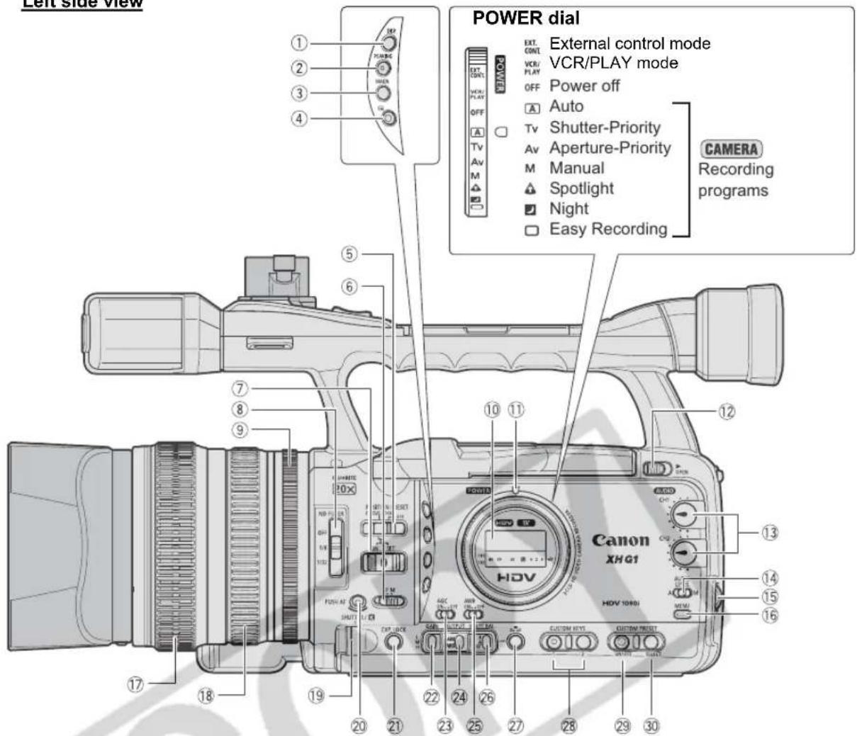
Left side view
text_image
Left side view POWER dial EXT. CONT. VCR/ PLAY OFF Power off Auto TV Shutter-Priority Av Aperture-Priority M Manual Spotlight Night Easy Recording CAMERA Recording programs Canon XHG1 HGV 1080J HGV 1080J EXTR. CONT. VCR/ PLAY OFF Auto TV Shutter-Priority Av Aperture-Priority M Manual Spotlight Night Easy Recording①DISP. (display) button (☐ 29)
②PEAKING button (☐ 37)
③ MAGN. (magnification) button (☐ 37)
④ (record review) button (30)
⑤ POSITION PRESET switch (☐ 34, 37)
⑥ Focus mode switch (☐ 35)
⑦ POSITION PRESET ON/SET switch (☐ 34, 37)
⑧ND FILTER switch (☐ 39)
⑨ Iris ring (☐ 56, 57)
⑩ Side panel (☐ 144)
⑪ POWER indicator
⑫ OPEN (open the LCD display) switch (☐ 19)
⑬ AUDIO CH1/CH2 dials (49)
⑭ AUDIO LEVEL switch (49)
⑮ SELECT/SET dial (25)
⑯ MENU button (☐ 25)
⑰ Focus ring (☐ 35)
⑱ Zoom ring (☐ 33)
⑲ SHUTTER dial (☐ 55)/K dial (☐ 62)
⑳ PUSH AF button (☐ 36)
②EXP. LOCK button (☐ 58)
② GAIN switch (☐ 58)
②3 AGC (automatic gain control) switch (☐ 60)
②4 OUTPUT switch (☐ 73)
⑲AWB (automatic white balance) switch (☐ 62)
②6 WHITE BAL. (white balance) switch (☐ 62)
⑳WHITE BAL. ● button (☐ 62)
28 CUSTOM KEYS (70)
⑲CUSTOM PRESET ON/OFF button (81)
③0 CUSTOM PRESET SELECT button (81)
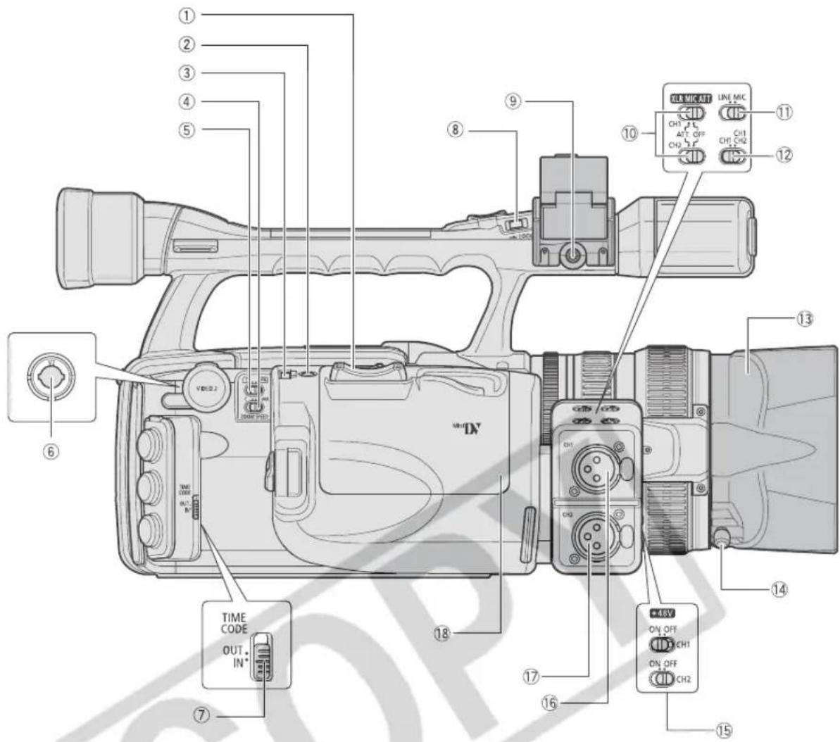
text_image
Labeled diagram of a video camera with numbered parts and control buttons for display①Grip zoom lever (☐ 33)
②PHOTO button (112)
③Zoom speed adjustment dial (☐ 33)
④ZOOM SPEED switch (☐ 33)
⑤ / (card/tape) switch (112)
⑥VIDEO2 terminal (☐ 99)
⑦TIME CODE switch* (44)
⑧ LOCK switch (28)
⑨ MIC (external microphone) terminal (47)
* XHG1 O
n l y
⑩ XLR MIC ATT. switches (☐ 48)
⑪LINE/MIC switch (☐ 48)
⑫ Input channel selection switch (☐ 48)
⑬ Lens hood (☐ 21)
⑭ Lens hood locking screw (☐ 21)
⑮ +48V switches (☐ 48)
⑯CH1 input terminal (☐ 48)
⑰CH2 input terminal (48)
⑱ Cassette compartment (23)
Front view
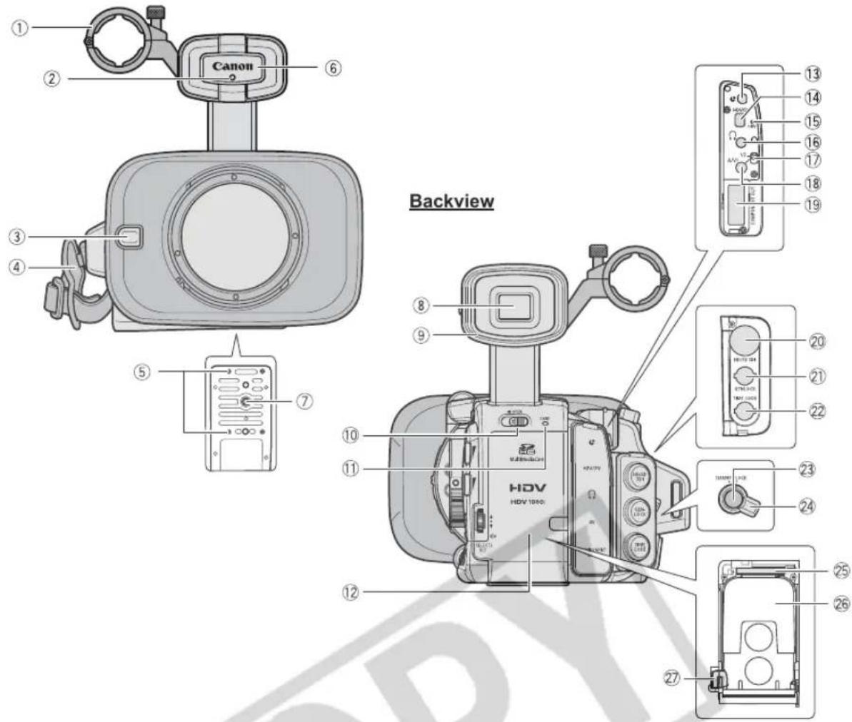
text_image
Canon Backview HDV HDV 1040① External microphone holder (☐ 48)
② Tally lamp (89)
③ External sensor for the Instant AF (☐ 35)
④Grip belt (☐ 20)
⑤ Attachment sockets for the optional TA-100 Tripod Adapter (☐ 155)
⑥ Remote sensor (☐ 22, 105)
⑦Tripod socket*
⑧ Viewfinder (18)
⑨ Dioptric adjustment lever (□□ 18)
⑩ OPEN (open the battery compartment) switch (☐ 15)
⑪ CARD access indicator (112)
⑫Battery/memory card compartment (15)
⑬ terminal
⑭ HDV/DV terminal (☐ 98, 106, 109)
⑮ HDV indicator (☐ 89)
⑯ (headphones) terminal
⑰ Video output selection switch (☐ 99)
⑱A/V1 terminal (☐ 97)
⑲COMPONENT OUT terminal (☐ 98)
⑳ HD/SD SDI terminal** (☐ 97)
②1 GENLOCK terminal** (☐ 44)
②TIME CODE terminal** (□□ 44)
②3 Start/stop button (☐ 27)
⑳ STANDBY lever (□ 28)
⑲ Memory card slot (☐ 24)
②6 Battery attachment unit (☐ 15)
⑳BATT. RELEASE latch (15)
* Do not use tripods with fastening screws longer than 5.5 mm (0.2 in.) as it may damage the camcorder.
** XHG1 only.
⑬ About the Terminal
(LANC) stands for Local Application Control Bus System. The terminal allows you to connect and control connected devices. Connect only devices with the mark to the terminal.
Operation cannot be guaranteed for connections with devices not bearing the mark.
Some buttons of connected devices may not operate or may operate differently than the buttons on the camcorder.
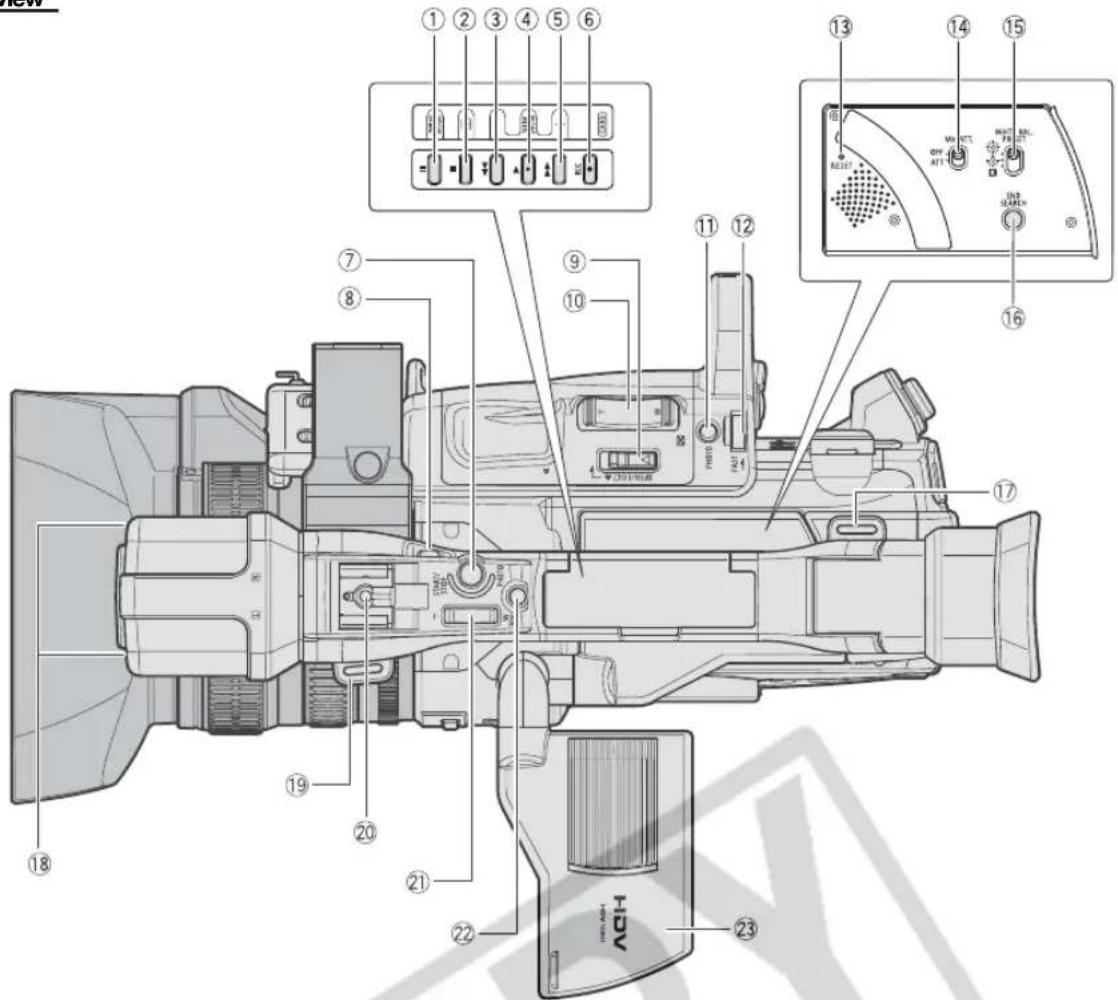
text_image
Technical diagram of a video camera with numbered components and labeled ports, likely for assembly or maintenance instructions.E
① (pause) button (95) /
DRIVE MODE button (115)
② (stop) button (☐ 95) /
(metering mode) button (117)
③ ◀◀ (rewind) button (□□ 95) /
CARD - button (120)
④▶ (play) button (□□ 95) /
SLIDESHOW button (☐ 120)
⑤▶▶ (fast forward) button (☐ 95) /
CARD + button (120)
⑥ ● REC (record) button (106)
⑦ Start/stop button (☐ 27)
⑧LOCK switch (☐ 28)
⑨ OPEN/EJECT ▲ switch (□□ 23)
⑩ Grip zoom lever (33)
⑪PHOTO button (112)
⑫ Zoom speed adjustment dial (☐ 33)
⑬ RESET button
⑭ MIC ATT. switch (☐ 48)
⑮ WHITE BAL. PRESET switch (☐ 62)
⑯ END SEARCH button (☐ 32)
⑰ Strap mount (☐ 20)
⑱ Microphone (☐ 47)
⑲ Strap mount (20)
⑳ Hot shoe (☐ 118)
②1 Handle zoom lever (☐ 33)
②PHOTO button (112)
②3 LCD display (☐ 19)
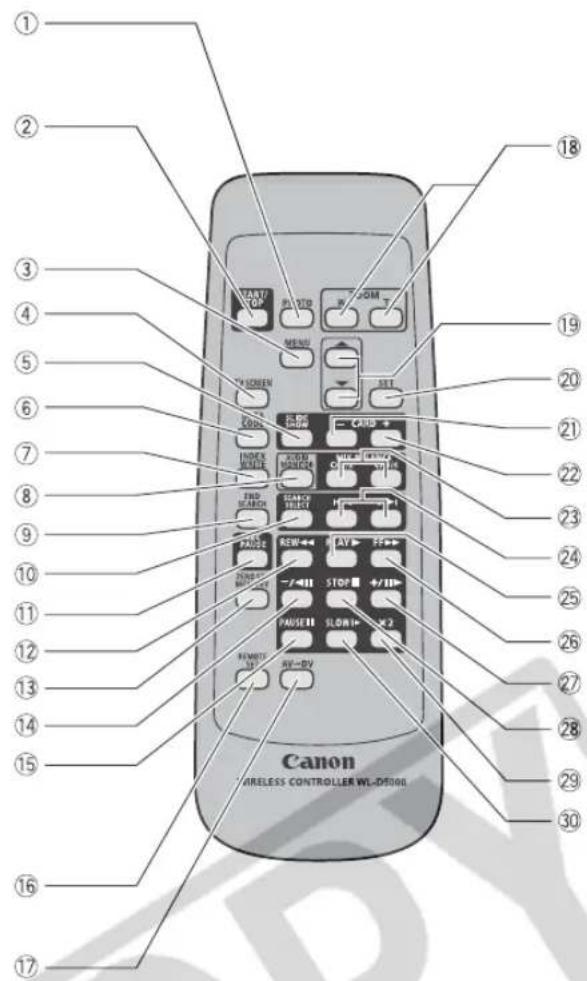
text_image
① ② ③ ④ ⑤ ⑥ ⑦ ⑧ ⑨ ⑩ ⑪ ⑫ ⑬ ⑭ ⑮ ⑯ ⑰ ⑱ ⑲ ⑳ ⑮ ⑯ ⑰ ⑱ ⑲ ⑳ ⑮ ⑯ ⑰ ⑱ ⑲ ⑳ ⑮ ⑯ ⑰ ⑱ ⑲ ⑳ ⑮ ⑯ ⑰ ⑱ ⑲ ⑳ ⑮ ⑯ ⑰ ⑱ ⑲ ⑳ ⑮ ⑯ ⑰①PHOTO button (112)
② START/STOP button (☐ 27)
③MENU button (25)
④ TV SCREEN button (☐ 90)
⑤ SLIDESHOW button (120)
⑥ DATA CODE button (104)
⑦INDEX WRITE button (71)
⑧ AUDIO MONITOR button (☐ 100)
⑨ END SEARCH button (☐ 32)
⑩SEARCH SELECT button (☐ 102, 103)
⑪ REC PAUSE button (106)
⑫REW ◀ button (☐ 95)
⑬ ZERO SET MEMORY button (☐ 101)
⑭ - /◀ button (☐ 95)
⑮ PAUSE ▪ button (□ 95)
⑯ REMOTE SET button (105)
⑰ AV→DV button (☐ 108)
⑱ Zoom buttons (33)
⑲Menu selection buttons (☐ 25)
⑳ SET button (☐ 25)
21 CARD - button (☐ 120)
22 CARD + button (120)
②3 MIX BALANCE buttons (☐ 100)
⑳ |◀◀/▶▶ buttons (□ 102, 103)
②5 PLAY ▶ button (☐ 95)
②6FF▶▶ button (☐ 95)
⑳ + / ▶ button (□ 95)
28 STOP ■ button (☐ 95)
29 ×2 button (☐ 95)
③0 SLOW ▶ button (□ 95)
Charging the Battery Pack
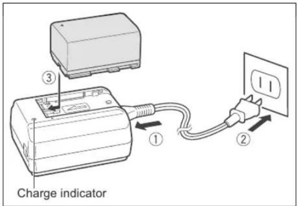
Disconnect the DC coupler from the power adapter before charging. Remove the terminal cover of the battery pack.
- Connect the power cord to the adapter.
- Plug the power cord into a power outlet.
-
Attach the battery pack to the adapter.
-
Press lightly and slide the battery pack in the direction of the arrow until it clicks.
-
The charge indicator starts flashing. The indicator will stay on when the charging is completed.
-
When the charging is completed, remove the battery pack from the adapter.
-
Unplug the power cord from the power outlet and disconnect it from the adapter.
text_image
Charge indicator ① ② ③Attaching the Battery Pack
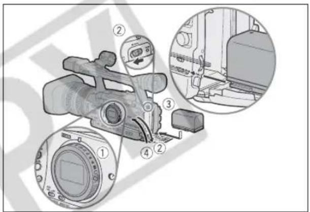
- Turn the POWER dial to OFF.
- Push the ◀ OPEN switch in the direction of the arrow to open the battery compartment cover.
- Insert the battery all the way into the compartment and press gently until it clicks.
- Close the battery compartment cover.
To Remove the Battery
- Turn the POWER dial to OFF.
- Push the ◀ OPEN switch in the direction of the arrow to open the battery compartment cover.
- Press the BATT.RELEASE latch left and pull out the battery.
- Close the battery compartment cover.
text_image
Technical diagram of a camera with numbered parts and magnified views highlighting internal componentsUsing a Household Power Outlet
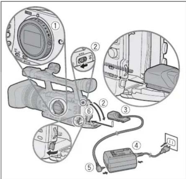
- Turn the POWER OFF.
- Attach the DC coupler to the camcorder.
Open the battery compartment cover and slide the DC coupler all the way into the compartment and press gently until it clicks.
- Connect the power cord to the power adapter.
- Plug the power cord into a power outlet.
- Connect the DC coupler to the adapter.
- Pass the cable through the special slot and close battery compartment cover.
- Detach the DC coupler after use.
Open the battery compartment cover, press the BATT.RELEASE latch left and pull out the DC coupler.
text_image
Diagram of a camera assembly with numbered parts and labeled components, including camera, cable, and power outlet connections.About the Built-in Rechargeable Lithium Battery
This camcorder has a built-in rechargeable lithium battery to retain the date, time and other settings. The built-in battery is recharged every time you use the camcorder. However, when you use the camcorder for only short times or do not use it for a period of over 3 months, it will discharge completely. In that case, recharge the built-in battery by powering the camcorder from a power outlet and leaving it with the POWER dial set to OFF for at least 24 hours.

○ Disconnect the DC coupler from the power adapter when charging a battery pack.
○ Turn off the camcorder before connecting or disconnecting the power adapter.
○ If the adapter is used close to a TV, it may cause picture interference. Move the adapter away from the TV or the antenna cable.
Do not connect to the power adapter any products not expressly recommended for use with this camcorder.

- If you connect a faulty power adapter or battery pack, the charge indicator turns off and the charging will stop.
○ The charge indicator serves also as an indication about the charge status.
0-50%: Flashes once per second
50-75%: Flashes twice per second
More than 75%: Flashes 3 times per second
100%: Continuously on
We recommend charging the battery pack in temperatures between 10 °C and 30 °C (50 °F and 86 °F). The charging time will vary depending on the surrounding temperature and the battery's initial charge condition.
○ In cold places the effective usage time of the battery will decrease.
We recommend that you prepare battery packs 2 to 3 times longer than you think you might need.
To conserve battery power, turn off the camcorder instead of leaving it in record pause mode.
U.S.A. and Canada only: The lithium ion/polymer battery that powers this product is recyclable. Please call 1-800-8-BATTERY for information on how to recycle this battery.

○ Charging, Recording and Playback Times
The following times are approximate and vary according to the charging, recording and playback conditions.
| Battery Pack | BP-930 BP-945 BP-950G BP-970G |
| Charging Time with the CA-920 Compact Power Adapter | 145 min. 220 min. 235 min. 320 min. |
XHG1
* Approximate times for recording with repeated operations such as start/stop, zooming, power on/off. Actual time may be shorter.
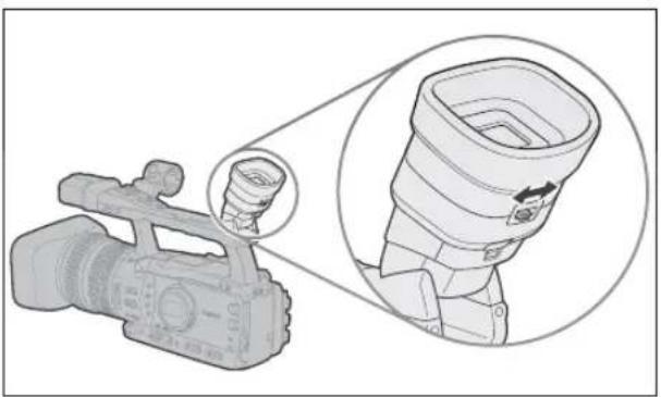
Dioptric Adjustment
Turn on the camcorder and adjust the dioptric adjustment lever.
natural_image
Illustration of a video camera with a magnified inset showing the lens and grip detail (no text or symbols)
Prevent direct sunlight from getting in the viewfinder. The viewfinder LCD may become damaged due to concentration of the light by the lens. Pay special attention when mounting the camcorder on a tripod, or during its transportation.
Adjusting the Viewfinder
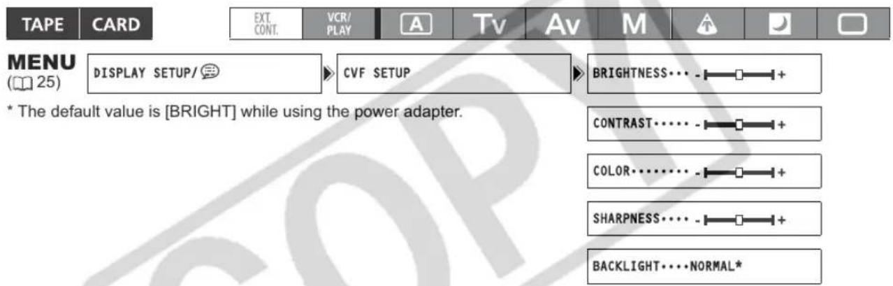
You can adjust the brightness, contrast, color, sharpness and backlight of the viewfinder. These adjustments will not affect your recording.
text_image
TAPE CARD EXT. CONT. VCR/ PLAY A Tsv Av M MENU (25) DISPLAY SETUP/ CVF SETUP BRIGHTNESS··· - ┌ ┌ ┌ + * The default value is [BRIGHT] while using the power adapter. CONTRAST······ - ┌ ┌ ┌ + COLOR······ - ┌ ┌ ┌ + SHARPNESS···· · ┌ ┌ ┌ + BACKLIGHT···· NORMAL*- Press the MENU button.
- Turn the SELECT/SET dial to select [DISPLAY SETUP/☐] and press the dial.
- Select [CVF SETUP] and then select [BRIGHTNESS], [CONTRAST], [COLOR], [SHARPNESS] or [BACKLIGHT].
- Adjust the setting with the SELECT/SET dial and press the dial.
- After the adjustment you will return to the [CVF SETUP] submenu. If necessary, change additional settings in the same way.
- Press the MENU button to close the menu.
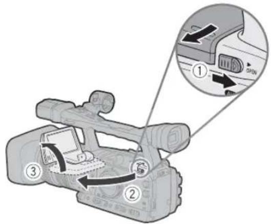
Using the LCD Display
text_image
Diagram of a digital camera with labeled parts and an inset showing the open control panel with directional arrows.- Slide the OPEN switch in the direction of the arrow to unlock the LCD panel.
- Pull out the LCD panel.
- Rotate the LCD panel and adjust it to the desired position.

○ You can change the LCD panel to black & white display (☐ 20).
By default, the viewfinder display is turned off while you use the LCD panel. However, you can change the settings to be able to use both displays simultaneously (☐ 20).
Adjusting the LCD Panel
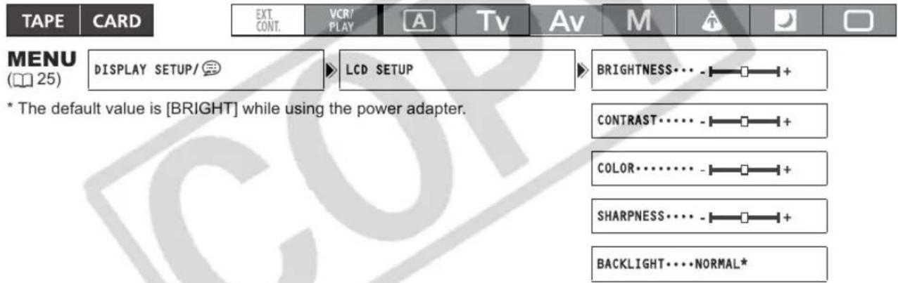
You can adjust the brightness, contrast, color, sharpness and backlight of the LCD Panel. These adjustments will not affect your recording.
text_image
TAPE CARD EXT. CONT. VCR/ PLAY A Tv Av M MENU (25) DISPLAY SETUP/ ℚ LCD SETUP BRIGHTNESS··· - ┌ ┌ ┌ + * The default value is [BRIGHT] while using the power adapter. CONTRAST······ - ┌ ┌ ┌ + COLOR········ - ┌ ┌ ┌ + SHARPNESS······ - ┌ ┌ ┌ + BACKLIGHT······ NORMAL*- Press the MENU button.
- Turn the SELECT/SET dial to select [DISPLAY SETUP/☐] and press the dial.
- Select [LCD SETUP] and then select [BRIGHTNESS], [CONTRAST], [COLOR], [SHARPNESS] or [BACKLIGHT].
- Adjust the setting with the SELECT/SET dial and press the dial.
- After the adjustment you will return to the [LCD SETUP] submenu. Change additional settings in the same way as necessary.
- Press the MENU button to close the menu.
Using the Viewfinder and the LCD Panel Simultaneously
By default, the viewfinder display is turned off while you use the LCD panel. Follow the procedure below to use both of them simultaneously.

text_image
TAPE CARD EXT. CONT. VCR/ PLAY A TV Av M A D MENU (25) DISPLAY SETUP/3V/F+LCD ON...OFF- Press the MENU button.
- Turn the SELECT/SET dial to select [DISPLAY SETUP/☐] and press the dial.
- Select [CVF+LCD ON], set it to [ON] and press the dial.
- Press the MENU button to close the menu.
Changing the Viewfinder and the LCD Panel to Black & White Display
The LCD display and the viewfinder are both color displays. Follow the procedure below to turn both of them to black & white display mode.

text_image
TAPE CARD EXT. CONT. VCR/ PLAY A Tv Av M A D MENU (25) DISPLAY SETUP/ CVF+LCD BW···OFF- Press the MENU button.
- Turn the SELECT/SET dial to select [DISPLAY SETUP/☐] and press the dial.
- Select [CVF+LCD BW], set it to [ON] and press the dial.
- Press the MENU button to close the menu.
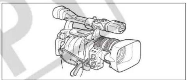
Fastening the Grip Belt
Adjust the grip belt so that you can reach the zoom lever with your index and middle finger, and the start/stop button with your thumb.
natural_image
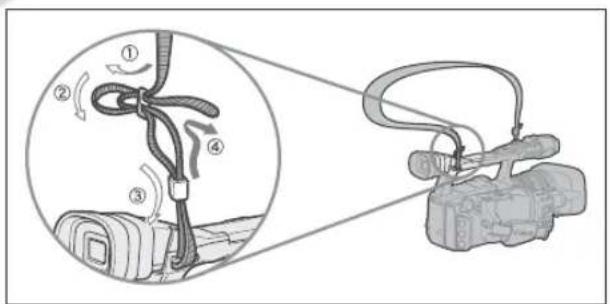
Line drawing of a video camera with attached mechanical components (no text or symbols)Attaching the Shoulder Strap
Pass the ends through the strap mount and adjust the length of the strap.
text_image
Diagram illustrating cable routing and camera setup with numbered components and directional arrows
Be careful not to drop the camcorder when adjusting the strap or the grip belt.
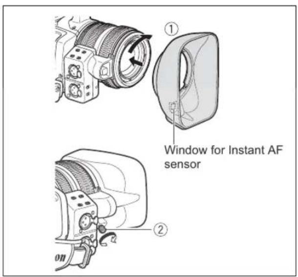
Attaching the Lens Hood
Attach the lens hood to protect the lens and shade it from stray light.
-
Place the lens hood on the front of the lens so that the window for the external Instant AF sensor faces down and turn it 90 degrees clockwise.
-
Be careful not to deform the lens hood.
-
Make sure that the lens hood is aligned with the thread.
-
Tighten the locking screw.
text_image
① Window for Instant AF sensor ② onUsing the Wireless Controller
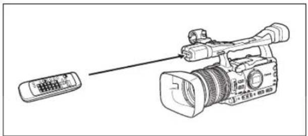
When you press the buttons on the wireless controller, point it at the camcorder's remote sensor.
natural_image
Line drawing of a professional video camera with a remote control unit (no text or symbols)Inserting the Batteries
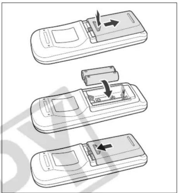
The wireless controller operates with two AA (R6) batteries.
- Open the battery cover.
- Insert the batteries following the + and - markings.
- Close the battery cover.
text_image
Diagram showing three steps of a remote control device with arrows indicating movement, including battery insertion and internal components.
The camcorder and wireless controller are equipped with 2 remote sensor modes (☐ 105). If the wireless controller does not work, verify that the camcorder and wireless controller are set to the same mode.
When the camcorder cannot be operated with the wireless controller, or when it can only be operated at very close range, replace the batteries. Make sure to replace both batteries at the same time.
The wireless controller may not work properly when the remote sensor is located under strong light sources or direct sunlight.
Use only videocassettes marked with the "MDY. For recording in HDV we recommend you use videocassettes compatible with the HDV standard.
1. Slide the OPEN/EJECT ▲ switch to open the cassette compartment cover.
The cassette compartment opens automatically.
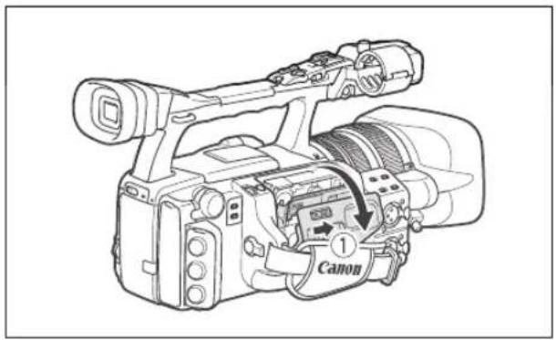
text_image
① Canon2. Load/remove the cassette.
- Insert the cassette straight, fully into the compartment with the window facing out.
- Remove the cassette by pulling it straight out.
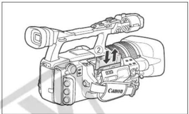
text_image
Canon3. Close the cassette compartment by pressing on the PUSH mark on the cover.
The cassette compartment will retract automatically.
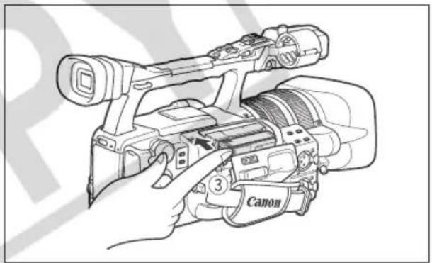
natural_image
Line drawing of a Canon digital video camera with handle and control panel (no text or symbols)4. Close the cassette compartment cover.
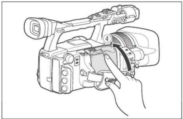
natural_image
Line drawing of a professional video camera with a hand adjusting the lens (no text or symbols present)
Do not interfere with the cassette compartment while it is opening or closing automatically.
○ Be careful not to get your fingers caught in the cassette compartment.

If the camcorder is connected to a power source, cassettes can be loaded/removed even if the POWER dial is set to OFF.
You can use only SDHC memory cards, SD memory cards or MultiMedia Cards (MMC) with this camcorder.
Inserting the Card
- Set the POWER OFF.
- Push the ◀ OPEN switch in the direction of the arrow to open the battery/memory card compartment cover.
- Insert the memory card straight, all the way into the memory card slot.
- Close the compartment.
Do not force the cover closed if the card is not correctly inserted.
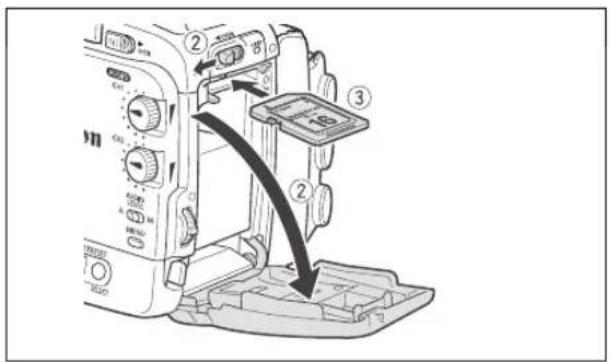
text_image
Diagram of a DSLR camera module with labeled parts and directional arrows indicating assembly or movement.Removing the Card
Do not forcefully remove the memory card without first pushing it in to release it.
- Set the POWER dial to OFF.
Make sure that the CARD indicator is not flashing before you turn off the camcorder.
- Push the ◀ OPEN switch in the direction of the arrow to open the battery/memory card compartment cover.
- Push the memory card once to release it and then remove the memory card.
- Close the compartment.
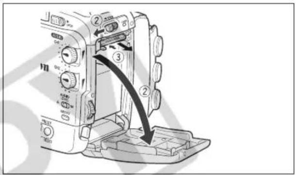
text_image
Diagram of a camera module with labeled parts and directional arrows indicating movement or assembly.
○ If you use memory cards other than the supplied one, make sure to initialize them with the camcorder (☐ 124).
Turn off the camcorder before inserting or removing the memory card. Otherwise, it may result in lost data.

- SDHC and SD memory cards have a write-protect switch to prevent their accidental erasure. When this switch is set to the LOCK position, images cannot be recorded on or deleted from the memory card.
○ Proper operation cannot be guaranteed for all memory cards.
About SDHC Memory Cards: SDHC (SD High Capacity) is the new type of SD memory cards with capacities over 2 GB. Please note that the specifications of SDHC memory cards are different from those of regular SD cards and you will not be able to use memory cards of over 2 GB with devices that do not support SDHC. However, SDHC devices (including this camcorder) are backward compatible and you can use regular SD cards with them.
Many of the camcorder's functions can be changed from the on-screen menu.
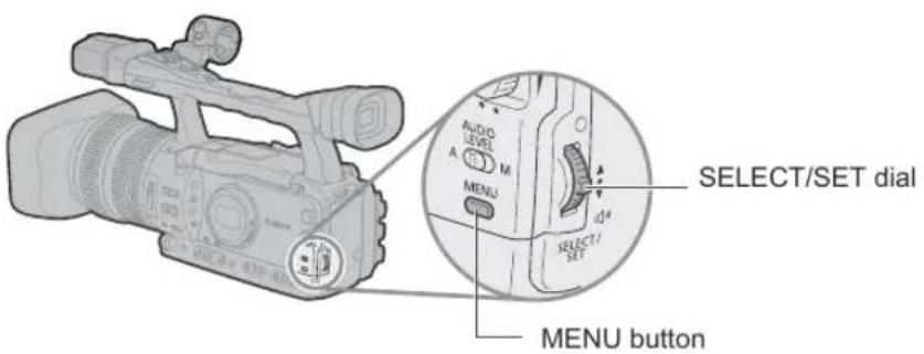
text_image
AUDIO LEVEL A M MENU SELECT/SET dial SELECT/1 SET MENU buttonSelecting Menus and Settings
- Press the MENU button to open the menu.
- Turn the SELECT/SET dial to select a submenu and press the dial.
- Turn the SELECT/SET dial to select a menu item and press the dial.
- Turn the SELECT/SET dial to select a setting option and press the dial.
- Press the MENU button to close the menu.

The ⬤, SET and MENU displays at the bottom of the screen will give you additional indications about what buttons to operate during each menu setting.
- You may find it more convenient to use the wireless controller to operate the menu. Press the MENU button on the wireless controller to open or close the menu. Use the menu selection buttons ▲ of the wireless controller instead of the SELECT/SET dial, and press the SET button on the wireless controller to save the settings or make a selection.
○ Unavailable items will appear grayed out.
○ Pressing the MENU button at any time closes the menu.
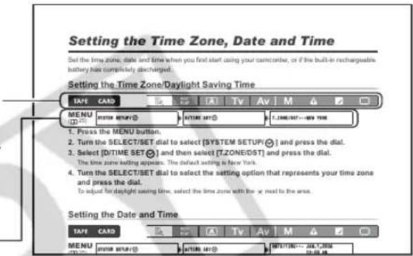
Setting the Time Zone, Date and Time
Set the time zone, date and time when you first start using your camcorder, or if the built-in rechargeable battery has completely discharged.
Setting the Time Zone/Daylight Saving Time

text_image
TAPE CARD EXT. CONT. VCR/ PLAY A Tv Av M MENU (25) SYSTEM SETUP/✓ D/TIME SET✓ T.ZONE/DST...NEW YORK- Press the MENU button.
- Turn the SELECT/SET dial to select [SYSTEM SETUP/☑] and press the dial.
- Select [D/TIME SET √] and then select [T.ZONE/DST] and press the dial.
The time zone setting appears. The default setting is New York.
- Turn the SELECT/SET dial to select the setting option that represents your time zone and press the dial.
To adjust for daylight saving time, select the time zone with the ✿ next to the area.
Setting the Date and Time

text_image
TAPE CARD EXT. CONT. VCR/ PLAY A Tv Av M A D MENU (25) SYSTEM SETUP/✓ D/TIME SET✓ DATE/TIME... JAN.1,2006 12:00 AM- Select [D/TIME SET √] and press the dial.
The year display starts flashing.
- Turn the SELECT/SET dial to select the first field of the date, and press the dial.
• The next part of the display starts flashing.
- Set the rest of the date and time in the same way.
- Press the MENU button to close the menu and start the clock.
Displaying the Date and Time while Recording
You can display the date and time in the lower left corner of the screen.

text_image
TAPE CARD EXIT. CONT. VCR/ PLAY A Tv Av M MENU (25) DISPLAY SETUP/ GUIDE INFO...OFFOpen the menu and select [DISPLAY SETUP/®]. Select [GUIDE INFO], set it to [D/T DISPLAY] and close the menu.

If you do not use the camcorder for a period of approximately 3 months, the built-in rechargeable battery will discharge completely and the date and time settings will be lost. In that case, recharge the built-in battery (☐ 16) and set the time zone, date and time again.
Before You Begin Recording
Make a test recording first to check if the camcorder operates correctly. If necessary, clean the video heads (1 4 7).
The default recording standard is HDV. About the audio recording, refer to the relevant chapter (47).
Recording
TAPE
CARD
EXT. CONT.
VCR/PLAY

Tv
Av
M

[NO TEXT]

- Remove the lens cap.
- Press the lock button and set the POWER dial to a recording program.
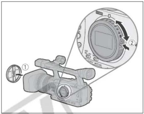
text_image
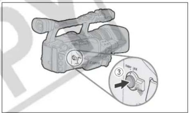
Diagram of a DSLR camera with labeled parts and a close-up inset showing the camera's dial and adjustment mechanism.3. Press the start/stop button to begin recording.
- The tally lamp lights up and the recording indicator ● appears on the screen.
- Press the start/stop button again to pause recording.
text_image
Diagram of a digital camera with labeled parts and an inset showing a close-up of the camera's dial.When You Have Finished Recording
- Set the POWER dial to OFF.
- Replace the lens cap.
- Remove the cassette.
- Disconnect the power source.

The end search, date search and index search functions may not work correctly if you mix recordings in HDV and DV standards on the same tape. We recommend not mixing recordings in different standards on the same tape.

○ After inserting a cassette, wait until the tape counter stops completely before you start recording.
Turn the PCVIER to OFF if you do not intend to use the camcorder for a long time.
If you do not remove the cassette, you can record the next scene without any noise or blank sections between the recordings even if you turn the camcorder off.
Low-angle Recording
The carrying handle is equipped with a duplicate set of recording and zoom controls, ideal for low-angle recording. Slide the LOCK switch in the direction of the arrow to prevent the accidental operation of these controls.

text_image
Zoom lever LOCK switch Start/stop buttonPower Saving Mechanisms
STANDBY Lever
Switch the STANDBY lever to the LOCK position to temporarily pause the recording and turn off all displays. In contrast to turning the POWER dial to OFF, in the standby mode the camcorder retains the exposure lock settings.
Power Save Function
In order to protect the tape and video heads, the camcorder will enter the power save mode (VCR STOP) after 4 minutes 30 seconds in record pause mode. If left 30 more seconds without any operation, the camcorder will automatically shut off. With the customized functions (☐ 83) you can also deactivate the power save function if you wish to make adjustments without worrying about losing your settings as a result of the automatic shut-off.
Once the camcorder entered the power save mode, press the start/stop button to start recording or press one of the custom keys (☐ 70) to which the [VCR STOP] function was assigned to return to record pause mode. If the camcorder automatically shut off (after 5 minutes), turn the POWER to OFF and then back to one of the recording programs.
VCR Stop Function
You can assign the [VCR STOP] function to either one of the two custom keys (☐ 70). In VCR stop mode the camcorder is only partially turned off: The camera section is powered normally while the recorder section is shut off. When you press the assigned custom key, you can make adjustments to the camera section as long as necessary without worrying about the power save function's 5-minute timer. To return to record pause mode, press the custom key to which the [VCR STOP] function was assigned.
Screen Displays while Recording
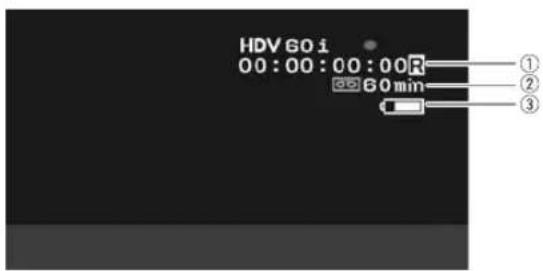
text_image
HDV 60 i 00:00:00:00R 60 min ① ② ③① Time code
You can select between drop frame or non-drop frame time code (☐ 42).
②Remaining tape
Indicates the remaining time of the tape in minutes.
“☐END” will appear when the tape reaches the end.
- When the time left is less than 15 seconds, the remaining tape time may not appear.
- Depending on the tape, the indication may not be displayed correctly.
③Remaining battery charge
The battery symbol indicates the charge status of the battery pack.

- "☐" starts flashing in red when the battery pack is empty.
- When you attach an empty battery pack, the power may turn off without displaying "☐".
- The actual battery charge may not be indicated accurately depending on the condition under which the battery pack and camcorder are used.
Selecting the On-Screen Displays
You can select the amount of information shown on the screen from full, partial or no display. Repeatedly pressing the DISP. button will cycle through the options in the following sequence.
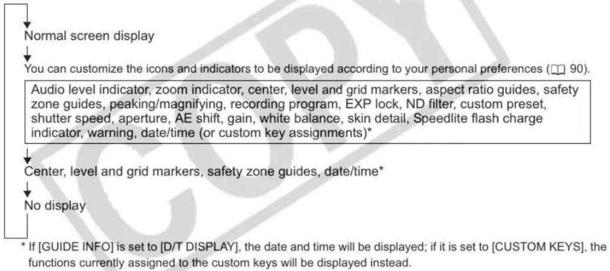
flowchart
graph TD
    A["Normal screen display"] --> B["You can customize the icons and indicators to be displayed according to your personal preferences (90)."]
    B --> C["Audio level indicator, zoom indicator, center, level and grid markers, aspect ratio guides, safety zone guides, peaking/magnifying, recording program, EXP lock, ND filter, custom preset, shutter speed, aperture, AE shift, gain, white balance, skin detail, Speedlite flash charge indicator, warning, date/time (or custom key assignments)*"]
    C --> D["Center, level and grid markers, safety zone guides, date/time*"]
    D --> E["No display"]
    E --> F["* If [GUIDE INFO"] is_set_to["D/T DISPLAY"], the date and time will be displayed; if_it_is_set_to["CUSTOM KEYS"], the functions currently assigned to the custom keys will be displayed instead.]

The camcorder's on-screen displays will also appear on a connected external TV or monitor.
Displaying the Markers
You can display the on-screen markers to help you accurately frame your subject. Select from a center marker, a horizontal level marker or a grid. You can also adjust the intensity of the markers display (☐ 88).

text_image
TAPE CARD EXT. CONT. VCR/ PLAY A Tv Av M
text_image
MENU (25) DISPLAY SETUP/EMARKERS···OFFOpen the menu and select [DISPLAY SETUP/☐]. Select [MARKERS], set it to [CENT. MARK.], [LEVEL MARK.] or [GRID] and close the menu.
Displaying the Aspect Ratio Guides
Use the aspect ratio guides as an indication to accurately frame subjects. You can select to display the aspect guides for 4:3, 13:9, 14:9, 1.66:1, 1.75:1, 1.85:1 or 2.35:1 (Cinemascope).

text_image
TAPE CARD EXT. CONT. VCR/ PLAY A Tv Av M
text_image
MENU (25) DISPLAY SETUP/ ASPECT GUIDE...OFFOpen the menu and select [DISPLAY SETUP/∅]. Select [ASPECT GUIDE], select a setting option and close the menu.
Displaying the Safety Zone Guide
The safety zone guide shows a frame including 80% or 90% of the screen area. Use it as an indication to accurately frame subjects.

text_image
TAPE CARD EXT. CONT. VCR/ PLAY A Tv Av M A □
text_image
MENU (25) DISPLAY SETUP/ nearby > SAFETY ZONE......OFFOpen the menu and select [DISPLAY SETUP/®]. Select [SAFETY ZONE], set it to [80%] or [90%] and close the menu.
Reviewing the Recording
text_image
MAGN S AGC ON (record review) button
text_image
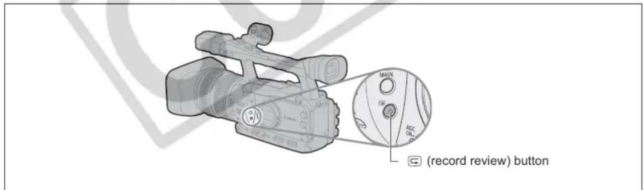
TAPE CARD EXT. CONT. VCR/ PLAY A Tv Av M A J □In record pause mode, this function allows you to review the last few seconds of your recording.
Press and release the (record review) button.
The camcorder rewinds the tape, plays back the last few seconds, and returns to record pause mode.

If the current video signal standard is different from the signal standard in which the tape was recorded, the recording will not be played back correctly.
Selecting the Signal Standard and Aspect Ratio
You can select the signal standard of your recording (high definition or standard definition) and, for standard definition recordings, also the aspect ratio of the recording. Since the displays on the camcorder have an aspect ratio of 16:9, when you select [SD4:3] the picture will appear in the center of the screen with black sidebars.
| TAPE | CARD |
| EXT.CONT. | VCR/PLAY | A | Tv | Av | M |
Open the menu and select [SIGNAL SETUP]. Select [SIGNAL STD], select a setting option and select [YES] to confirm the selection and close the menu.
• [HD]: To record on the tape in HDV standard or to use the camcorder as a high-definition (HD) camera.
- [SD16:9], [SD4:3]: To record on the tape in DV standard or to use the camcorder as a standard-definition (SD) camera. Select the aspect ratio as desired.

To play back recordings made with a 16:9 aspect ratio change the settings of the TV as necessary (refer to the instruction manual of the connected TV). To play back widescreen recordings on a TV set with 4:3 aspect ratio, change the [LETTERBOX] setting accordingly (☐☐ 99). TV sets equipped with the ID-1 system will switch automatically to a widescreen (16:9) display.
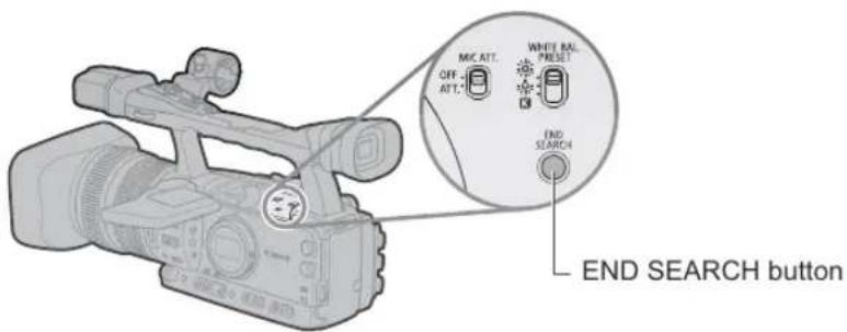
You can use this function to locate the end of the last recorded scene.
text_image
MIC ATT. OFF ATT WHITE BAL PRESET END SEARCH END SEARCH buttonTAPE
CARD
EXT. CONT.
VCR/PLAY

Tv
Av
M


Press the END SEARCH button.
• →| appears.
- The camcorder rewinds/fast forwards the tape, plays back the last few seconds of the recording and stops the tape.
- Pressing the button again cancels the search.

○ The end search function cannot be used once you unload the cassette.
The end search function may not work correctly if there is a blank section between recordings on the tape or if you mix recordings in HDV and DV standards on the same tape.
You can operate the zoom from either the side grip or the carrying handle. You can also use the zoom ring on the lens or the zoom buttons on the wireless controller. With the customized functions (☐ 83) you can change the direction of the adjustment when you turn the zoom ring, turn the high-speed zoom on/off or change the zoom indicator to a graphic bar or a numeric value display.
E

text_image
Zoom lever Zoom ring ZOOM SPEED switch ZOOM SPEED dial Zoom lever Zoom buttonsTAPE CARD
EXT. CONT. VCR/ PLAY A Tv Av M
Move the zoom lever toward W to zoom out (wide-angle). Move it toward T to zoom in (telephoto).
About the Variable Zoom Speeds
Zoom lever on the side grip:
When the ZOOM SPEED switch is set to C (constant), the zoom speed itself does not change, but you can select one of 16 levels of zoom speed with the ZOOM SPEED dial (a number indicating the level will be displayed next to the zoom indicator).
When the ZOOM SPEED switch is set to VAR (variable), the zoom speed will depend on how you operate the zoom lever: Pressing gently will result in a slower zoom; pressing harder in a faster zoom.
Zoom speed (from wide-angle to telephoto):
C: Level 1: approx. 60 seconds
VAR: approx. 2.6*–60 seconds
Level 16: approx. 2.6* seconds
* If the custom function [HIGH-SPEED ZOOM] is set to [ON], the zoom speed will be approx. 1.5 seconds instead. In CAMERA-CARD mode the zoom speed will be approx. 1.5 seconds, regardless of the custom function setting.
Zoom ring:
The zoom speed depends on how fast you turn the zoom ring.
Zoom buttons on the carrying handle:
The zoom speed itself does not change, but it can be set to one of 16 levels with the ZOOM SPEED dial. This is the same zoom speed setting as when the ZOOM SPEED switch is set to C.
Zoom buttons on the supplied wireless controller:
The zoom speed is constant and cannot be adjusted.
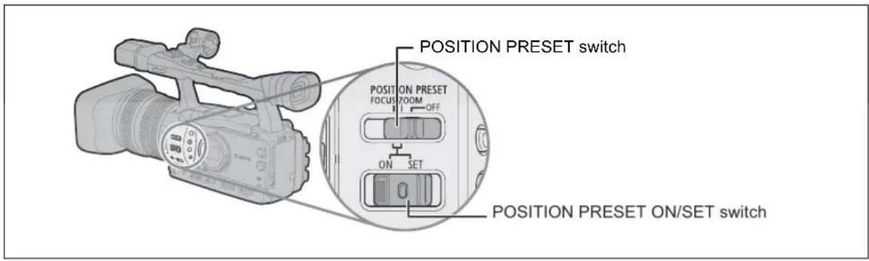
Zoom Preset
This function enables any given zoom setting to be memorized and to return to that zoom setting instantly.
text_image
POSITION PRESET switch POSITION PRESET FOCUS ZOOM OFF ON SET POSITION PRESET ON/SET switchPresetting the Zoom
| TAPE | CARD | EXT.CONT. | VCR/PLAY | A | Tv | Av | M |
- Set the POSITION PRESET switch to ZOOM.
- Move the POSITION PRESET ON/SET switch to SET.
The preset zoom position appears in yellow on the zoom indicator.
Returning to the Preset Zoom Position
Move the POSITION PRESET ON/SET switch to ON.
The camcorder returns to the preset zoom position.

To return to the preset zoom position the camcorder uses the speed set for the constant zoom speed (when the ZOOM SPEED switch is set to C).
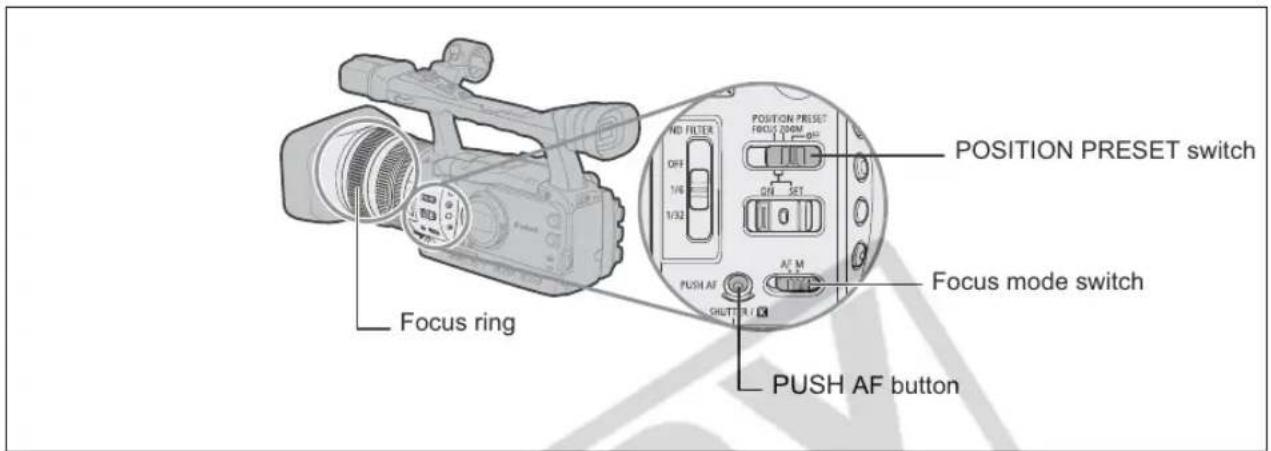
The camcorder can be set to Autofocus or Manual Focus.
Autofocus
The autofocus can be set to Normal AF or Instant AF*. The camcorder has also a Push-AF function to allow for a temporary autofocus while focusing manually. When you operate the PUSH AF button, the Instant AF is activated, regardless of the current setting of the AF mode.
Manual Focus
With the customized functions (☐ 83) you can change the direction of the adjustment when you turn the focus ring and its response sensitivity ([NORMAL] or [SLOW]). To make it easier to focus manually, you can also make use of the Peaking and Magnifying display functions (☐ 37).
* The Instant AF function can also be used combined with the Push-AF function so you can obtain a very fast initial automatic focus even while focusing manually.
text_image
NO FILTER OFF 1/6 1/32 POSITION PRESET FOCUS ZOOM ON SET 0 PUSH AF SHIFT R A' M Focus mode switch PUSH AF button Focus ring| TAPE | CARD |
| EXT.CONT. | VCR/PLAY | A | Tv | Av | M |
Autofocus
The autofocus is set when the focus mode switch is set to AF. The camcorder uses the TTL autofocus system with a focusing range of 2 cm (0.8 in.) (at wide-angle from the front of the lens barrel) to ∞.
The camcorder focuses on the subject in the center of the screen.
Follow the procedure below to change the autofocus mode.

text_image
CAMERA SETUP AF MODE ... INSTANT AFOpen the menu and select [CAMERA SETUP]. Select [AF MODE], select a setting option and close the menu.
[INSTANT AF]: The focus is adjusted at the highest speed. This mode is useful even when recording in very bright or low-light surroundings. The TTL system and the external sensor are both used for focusing.
[NORMAL AF]: The autofocus adjustment is made at a stable speed. Only the TTL system is used in this mode making it appropriate for use also with the optional Wide Converter attached.
Temporary Focus Override
Even while in autofocus mode, turn the focus ring to temporarily focus manually.
The camcorder will return to autofocus as soon as you release the focus ring.
Temporary Instant AF
During manual focus or Normal AF, press the PUSH AF button and hold it pressed down.
The autofocus (Instant AF) is activated as long as you hold the PUSH AF button pressed down.

When recording under bright conditions, the camcorder sets a small aperture value, and the picture may appear blurred. Turn the built-in ND filter on/off according to the screen display (☐ 39).

When you attach the optional Wide Converter to the camcorder, set the camcorder to a recording mode other than □ Easy Recording and set the autofocus mode to Normal AF. Also, avoid using the Push AF function.
○ In 30F and 24F mode, autofocus takes longer than in the 60i mode.
When recording under dark conditions, the focusing range narrows and the picture may appear blurred.
○ Autofocus may not work well on the following subjects. In that case, focus manually.
- Reflective surfaces
- Subjects with low contrast or without vertical lines
- Fast moving subjects
- Through dirty or wet windows
- Night scenes
Manual focus
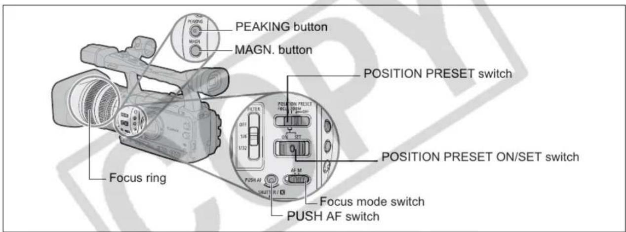
text_image
PEAKING button MAGN. button POSITION PRESET switch 0/1 1/6 1/32 PULSE ON PRESET ON/SET switch 0/5 SET AF M PUSH AF 0/1 Focus mode switch PUSH AF switch

text_image
EXT. CONT. VCRI/ PLAY A Tv Av M Å ↓ □- Set the focus mode switch to M.
"MF" is displayed on screen.
- Zoom in to telephoto.
- Turn the focus ring to adjust the focus.
With the customized functions (☐ 83) you can change the direction of the adjustment when you turn the focus ring and its response sensitivity ([NORMAL] or [SLOW]).
- Operate the zoom to reframe the subject.
If you focus manually and then leave the camcorder with the power turned on, you may lose the focus on your subject. This possible slight shift in focus is a result of the internal temperature rising in the camcorder and lens. Check the focus before resuming shooting.

☐ The manual focus cannot be selected in the ☐ Easy Recording mode. Even if you set the focus mode switch to M, the autofocus (Instant AF) will still be activated.
The focal distance to the subject will be displayed for approx. 3 seconds when you switch from autofocus to manual focus or when you operate the focus ring in the manual focus mode. It will also be displayed with the focus preset. With the customized functions (☐ 83) you can change the units for the distance display (meter or feet) and with the custom display (☐ 90) you can select when to display this information (always, never, or only upon the operation of the focus ring).
○ Use the distance display as an estimate.
∞: Infinity focus ∞-: Over infinity focus
Using the Focus Assist Functions (Peaking and Magnifying)
In order to make manual focusing easier, you can use two assist functions: Peaking emphasizes the outlines of the subject creating a clearer contrast, and Magnifying enlarges the image on the screen. You can also combine both for a greater effect. With the customized functions (☐ 83) you can set the display to change automatically to black & white while using the focus assist functions.
Peaking
While recording or in record pause, press the PEAKING button.
• The outlines of the subject will be emphasized.
- Press the button again to cancel the function.
Magnifying
In record pause, press the MAGN. button.
- The central part of the screen will be magnified approximately 2x.
- Press the button again to cancel the function.

The Peaking and Magnifying functions will not affect your recordings. However, the magnified picture will be output as is to the HD/SD SDI terminal (XHGI only) and the HDV/DV terminal.
○ The Magnifying function will be canceled as you start recording.
- You can use the custom keys (☐ 70) to prevent the accidental operation of the MAGN. button. With the customized functions (☐ 83) you can also change the operation of the MAGN. button (normal or long press).
Focus Preset
This function enables a focus setting to be memorized and to return to that focus setting instantly. You can also select the speed at which the camcorder returns to the preset focus setting.
Presetting the Focus
| TAPE | CARD | EXTCONT. | VCR/PLAY | A | Tv | Av | M |
1. Set the focus mode switch to M.
"MF" appears.
2. Set the POSITION PRESET switch to FOCUS.
The focus preset speed currently selected appears.
3. Adjust the focus with the focus ring.
4. Move the POSITION PRESET ON/SET switch to SET.
"MF" and the focus preset speed display turn yellow.
Setting the Focus Preset Speed

CAMERA SETUP F SPEED PSET
• HIGH
Open the menu and select [CAMERA SETUP]. Select [F SPEED PSET], select a setting option and close the menu.
The selected speed appears next to "MF".
Returning to the Preset Focus Setting
Move the POSITION PRESET ON/SET switch to ON.
The camcorder returns to the preset focus setting.
When recording in bright surroundings, the camcorder will set a small aperture value and the picture may appear blurred. Turn the ND filter on/off according to the screen display.
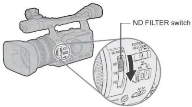
text_image
ND FILTER switch ND FILTER 0/7 1/6 1/32 POSITION HOLD 200M OK SET PC MWhen using a recording program other than M Manual and if the AGC switch is set to ON, the following displays appear:
| Screen display | What it means | What you should do |
| No display | ND filter is not activated | - |
| “ND” | ND filter is activated | - |
| “ND ON” flashes | ND filter required | Turn on the ND filter |
| ND “ON” flashes | Higher density or external ND filter required | Select a higher density built-in ND filter or attach an external ND filter to the lens* |
| ND “OFF” flashes | Built-in ND filter not required | Turn off the ND filter |
| “ND” flashes in red | Built-in ND filter incorrect setting | Set the ND FILTER switch to an appropriate density |
* If you have no external ND filter available, use the Tv mode and set a high shutter speed, or use the Av mode and set a small aperture value.

Depending on the scene, the color may change when turning the ND filter on/off. In such case, setting a custom white balance may be effective (☐ 63).
You can select from the following frame rates depending on the recording mode:
HD 60i, 30F, 24F (2:3 pulldown-converted)
SD 60i, 30F, 24F (2:3 pulldown-converted or 2:3:3:2 pulldown-converted)
60i Mode
Records in 60 fps interlaced mode, the same as standard-definition TV signals.
30F Mode
Records in 30 fps progressive mode and outputs signals converted into 60 fps interlaced. Video output from the HDV/DV terminal will be in 30p.
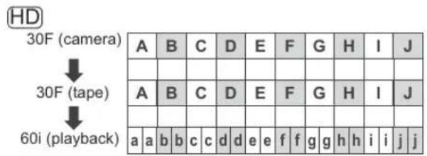
text_image
HD 30F (camera) ↓ 30F (tape) ↓ 60i ( playback) A B C D E F G H I J A B C D E F G H I J a a b c c d e f f g h h>i>i j(j)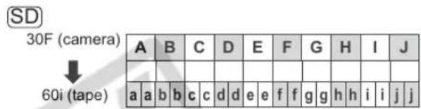
text_image
SD 30F (camera) ↓ 60i (tape) A B C D E F G H I J a a b b c c d d e e f f g h h h h h h h h h h h h h h h h h h h h h h h h h h h h h h h h h h h h h h h h h h h h h h h h h h h h h h h h h h h h h h h h h h h h h h h h h h h h h h h h h h h h h h h h h h h h h h h h h h h h parties24F Mode
Records in 24 fps progressive mode like movie cameras, creating a true cinematic feel to the picture.
HD The video signal will be output from the HDV/DV terminal in 24 fps progressive mode. The signal output from the HD/SD SDI terminal (XHG1 only) and the COMPONENT OUT terminal will be down-converted to 60i using the 2:3 pulldown method.
SD
24F (2:3) Mode
Signals are down-converted to 60i using the 2:3 pulldown method. This 24F mode is suited for playback on a TV screen but may require the extension/compression of some frames while editing.
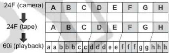
text_image
24F (camera) ↓ 24F (tape) ↓ 60i ( playback)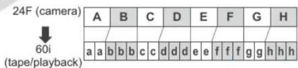
text_image
24F (camera) ↓ 60i (tape/playback)24F (2:3:3:2) Mode
Signals are down-converted to 60i using the 2:3:3:2 pulldown method. This 24F mode is ideal for extracting true 24 frames per second in order to transfer to film simply by discarding the 3:3 adjacent frames (bc and fg in the figure).
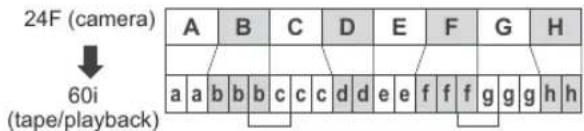
text_image
24F (camera) ↓ 60i (tape/playback)Selecting the Frame Rate

text_image
TAPE CARD EXT. CONT. VCR/ PLAY A Tv Av M MENU (25) SIGNAL SETUP FRAME RATE...60iOpen the menu and select [SIGNAL SETUP]. Select [FRAME RATE], select a setting option and select [YES] to confirm the selection and close the menu.
The selected frame rate appears on-screen.
SD Selecting the 24F Pulldown Mode

text_image
TAPE CARD EXT. CONT. VCR/ PLAY A Tv Av M A
text_image
MENU (□ 25) CAMERA SETUP ▶ 24F MODE SEL·2:3Open the menu and select [CAMERA SETUP]. Select [24F MODE SEL], select a setting option and close the menu.
• [2:3]: "24F" appears in white.
• [2:3:3:2]: "24F" appears in orange.

If you are using an editing system that does not support the 2:3:3:2 pulldown method, make sure to record in 24F 2:3 pulldown mode.
Video recorded in 24F or 30F can only be played back with compatible devices and can only be edited with software that supports these frame rates. For software and hardware compatibility consult the relevant customer support.
Selecting the Frame Setting
When recording in a mode other than SD at a frame rate of 24F, you can select between a drop frame or non-drop frame time code.

text_image
TAPE CARD EXT. CONT. VCR/ PLAY A Tv Av M MENU (25) SIGNAL SETUP TIME CODE FRAME SETTING·DROPOpen the menu and select [SIGNAL SETUP]. Select the [TIME CODE] submenu and then [FRAME SETTING]. Select a setting option and close the menu.
When you select the [NON DROP] setting or when you select 24F frame rate in SD mode, "NDF" will appear on the side panel display.
Selecting the Running Mode
When recording in a mode other than SD at a frame rate of 24F, you can select the running mode of the camcorder's time code. You can enter the initial value for the [FREE-RUN] and the [REC-RUN PS.] settings.
[REC-RUN]: The time code runs only when recording.
[REC-RUN PS.]: The time code runs only when recording starting from a preset value.
[FREE-RUN]: The time code runs regardless of the operation of the camcorder.

text_image
TAPE CARD EXT. CONT. VCR/ PLAY A Tv Av M MENU (S) 25) SIGNAL SETUP TIME CODE COUNT-UP·····REC-RUN- Open the menu and select [SIGNAL SETUP]. Select the [TIME CODE] submenu and then [COUNT-UP]. Select a setting option and close the menu.
[REC-RUN]: Close the menu.
[REC-RUN PS.], [FREE-RUN]: Continue the procedure below to set the initial value.
- Select [SET].
The hours display flashes.
- Set the time code's initial value.
Turn the SELECT/SET dial to set the value for the hours and press the dial. The next field of the display starts flashing. Set the value for the minutes, seconds and frames in the same way.
- Close the menu.

○ About the time code display
- [REC-RUN]: The time code will be displayed with an R next to it.
- [REC-RUN PS.]: The time code will be displayed in blue with a P next to it.
- [FREE-RUN]: The time code will be displayed in blue with an F next to it.
- External Time Code: The time code will be displayed in blue with an E next to it.
- Time Code Hold: The time code will be displayed with an H next to it.
- Playback: No time code display.
When you select [FREE-RUN], the time code starts to run the moment you press the MENU button in the middle of the setting, or when you press the SELECT/SET dial after setting the value for "frames" in step 3.
To reset the time code to [00:00:00:00], select [RESET] in step 2.
In 24F (in SD) mode, the "frames" value of the time code is set in multiples of 5. When you change the frame rate from 60i/30F to 24F, the "frames" value of the time code will automatically become a multiple of 5.
When you mix drop frame and non-drop frame time codes (including 24F frame rate in SD mode), there might be a discontinuity in the time code at the point where the recording starts.
When recording over existing scenes: When a time code discontinuity occurred near the recording start point, the time code at the point where the recording starts may be discontinuous.
As long as the built-in rechargeable lithium battery is charged, the free-run time code continues to run even if you disconnect the battery pack.
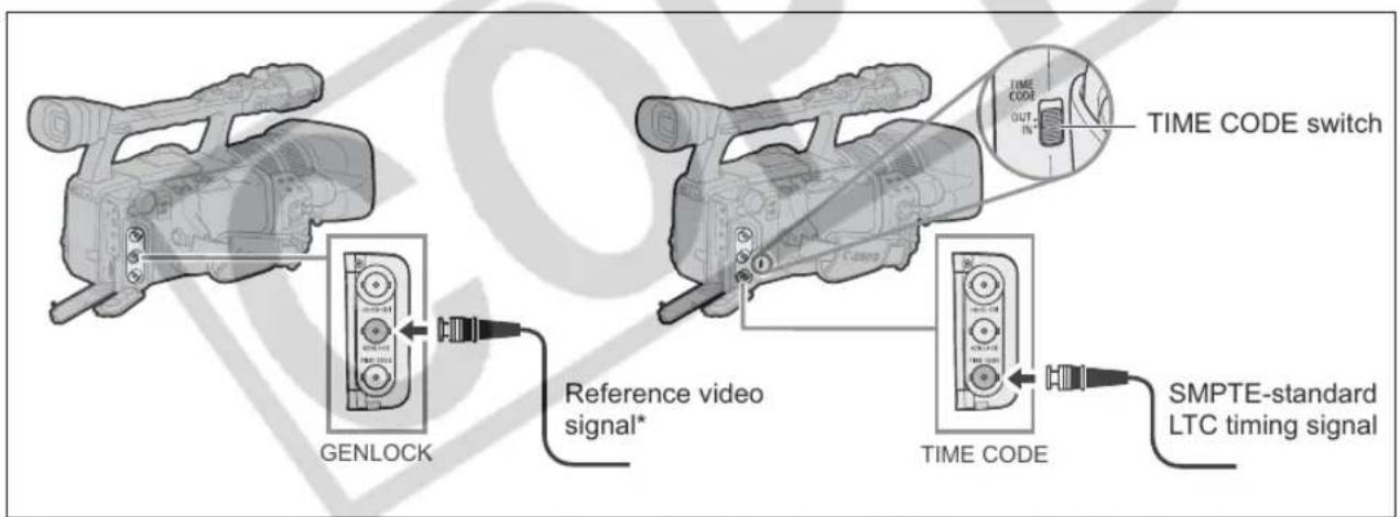
You can synchronize this camcorder's time code to an external time code generator. Also you can include in the recording the user bit signal received from the TIME CODE terminal (46). The camcorder offers the following synchronization options.
Genlock
When a reference sync signal (analog blackburst or tri-level signal) is input through the GENLOCK terminal, the V and H phases of the camcorder's time code will be automatically synchronized to it.
Time Code IN
Set the TIME CODE switch to IN to start the Time Code IN mode.
An external SMPTE-standard LTC timing signal received from the TIME CODE terminal will be recorded as the time code on the tape. The user bit of the external timing signal can also be recorded on tape.
Time Code OUT
Set the TIME CODE switch to OUT to start the Time Code OUT mode.
The camcorder's internal time code is sent out from the TIME CODE terminal as a standard LTC timing signal. When you set [SDI OUTPUT] to [ON] the time code data will also be output through the HD/SD SDI terminal.
| CAMERA * | VCR/PLAY | CAMERA·CARD | VCR/PLAY·CARD | |
| Genlock | ● | - | ● | - |
| Time Code/User bit IN | ● | - | - | - |
| Time Code OUT | ● | ● | - | - |
* In SD mode, Time Code IN is not available if you select the 24F frame rate (the mode will be canceled and the "TC- (IN OUT)" display on the side panel will disappear).
Connection Diagram
text_image
GENLOCK Reference video signal* TIME CODE switch TIME CODE OUT. IN SMPTE-standard LTC timing signal* As a reference video signal input you can use either an HD Y signal or an NTSC composite video signal.

While a time code signal is being received, the [FRAME SETTING] and [COUNT-UP] settings of the camcorder will be ignored and the external time code's drop-frame bit will be used instead (if the external time code is non-drop frame, "NDF" will appear on the side panel display).
Once the Genlock or Time Code IN synchronization stabilizes (after approx. 10 seconds), the external time code lock will be retained even if you disconnect the cable from the TIME CODE terminal. However, if you perform one of the following while the cable is disconnected, the time code will lag slightly; the correct time code will be restored once you reconnect the cable.
- Turn the camcorder off/on.
- Change the PUEVEa mode other than .
- Change the position of the ☐(card/tape) switch.
- Change the [SIGNAL STD] or [FRAME RATE] setting.
☐ If the external time code signal is incorrect or there is no input signal, the internal time code (according to the [TIME CODE]/[COUNT-UP] settings) will be recorded on the tape instead.
○ If the external Genlock signal is incorrect or there is no input signal, the external time code being recorded on tape may be incorrect.
When recording in SD mode, Time Code IN is not available if you select the 24F frame rate (the mode will be canceled and the "TC-(IN OUT)" display on the side panel will disappear).
When the camcorder is set to HD standard, Genlock synchronization is possible even if the external Genlock signal is in SD standard. However, the Genlock synchronization will not be possible if the external Genlock signal is in HD standard but the camcorder is set to SD standard.
The phase difference between the external Genlock signal and the camcorder is initially set to 0; it can be adjusted within the range of approx. ±0.4 H (-1023 to +1023) with the [GENLCK ADJST] setting (☐ 127).
- Genlock synchronization is not possible when the camcorder is set to HD standard and [SDI SPEC.] is set to [SD LOCKED].
○ About the Side LCD Panel Indications
- "GENLOCK" will flash until the synchronization stabilizes and will stay on once the phase synchronization has stabilized.
- "TC-(IN OUT)" indicates that the Time Code IN or Time Code OUT synchronization is available with the TIME CODE switch.
- "EXT-LOCK" indicates that the camcorder has locked on to an external time code signal.
The user bit display can be selected from the date or the time of recording, or an identification code consisting of 8 characters in the hexadecimal system that is useful for labeling tapes. There are sixteen possible characters: the numbers 0 to 9 and the letters A to F.
XHG1 If a user bit is being received along with an external time code, you can also choose to record the external user bit on tape.

text_image
TAPE CARD EXT. VCR/ TV Av M CONT. CONT. PLAY A A MENU (25) RECORDING SETUP UB SELECT...00 00 00 00- Open the menu and select [RECORDING SETUP]. Select [UB SELECT], select a setting option and press the SELECT/SET dial.
If you selected [00 00 00 00], the user bit set/reset options appear; continue with the procedure below. Otherwise, close the menu.
If you selected [00 00 00 00]:
- Select [SET].
The first character of the user bit flashes.
- Turn the SELECT/SET dial to select a number or letter and press the dial.
The next character of the user bit starts flashing. Set the rest of the user bit in the same way.
- Close the menu.

To reset the user bit to [00 00 00 00], select [CLEAR] in step 2.
The user bit can be recorded when recording with the camcorder or from analog devices. The user bit set in the camcorder cannot be recorded when recording from digital devices (DV or HDV).
Displaying the User Bit

text_image
TAPE CARD EXT. VCR/ Tv Av M CONT. CONT. PLAY A A MENU (25) DISPLAY SETUP/ UB DISPLAY-OFFOpen the menu and select [DISPLAY SETUP/®]. Select [UB DISPLAY], set it to [ON] and close the menu.
Recording an External User Bit

text_image
TAPE CARD EXT. CONT. VCR/ PLAY A TV Av M MENU (25) RECORDING SETUP UB REC...INT.USR-BITOpen the menu and select [RECORDING SETUP]. Select [UB REC], select [EXT.USR-BIT] and close the menu.
You can select to record audio from the built-in microphone or from an external microphone connected either to the MIC terminal or to the XLR terminal.
XHG1 While recording, the sampling frequency of the output signal from the HD/SD SDI terminal will be 48 kHz regardless of the audio input.
| TAPE | CARD | EXT.CONT. | VCR/PLAY | A | Tv | Av | M |
HDV The audio transfer rate is 384 Kbps and the sampling frequency is 48 kHz.
DV You can choose to record in 16 bit audio mode (sampling frequency 48 kHz), or 12 bit audio mode (sampling frequency 32 kHz).
- In 12 bit audio mode, only audio channels 1 and 2 are used for recording, leaving the adjacent channels available for adding a new audio track.
• Audio cannot be dubbed using this camcorder. - Audio recorded with this camcorder is "locked" audio except for the audio recorded from an analog input or from a digital input if you select the Unlock mode.
SD Selecting the DV Audio Mode
| MENU(25) | AUDIO SETUP | DV AUDIO...16bit |
Open the menu and select [AUDIO SETUP]. Select [DV AUDIO], select a setting option and close the menu.
Selecting the Microphone's Audio Recording Mode
You can select the most appropriate setting, given your recording conditions, for recording audio with the built-in microphone.
| MENU(25) | AUDIO SETUP | MIC MODE···NORMAL |
Open the menu and select [AUDIO SETUP]. Select [MIC MODE], select a setting option and close the menu.
[NORMAL]: To record audio under usual conditions.
[VOICE Ⓞ: To record mainly people's voices.
[WS ≈/♀]: To reduce the background sound of wind when recording outdoors in windy surroundings (for example, on a beach or close to buildings). Note that when you use the wind screen some low-frequency sounds may be suppressed along with the sound of wind.
Selecting the Sensitivity of the Built-In Microphone
You can change the sensitivity of the built-in microphone to [NORMAL] or [HIGH] (+6 dB) to match the recording conditions.
| MENU(25) | AUDIO SETUP | MIC SENSIT....NORMAL |
Open the menu and select [AUDIO SETUP]. Select [MIC SENSIT.], select a setting option and close the menu.
[NORMAL]: To record audio under usual conditions.
[HIGH]: To record audio at a higher volume.
text_image
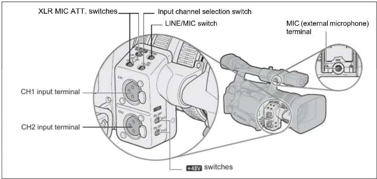
XLR MIC ATT. switches Input channel selection switch LINE/MIC switch MIC (external microphone) terminal CH1 input terminal CH2 input terminal +48V switchesConnecting to the MIC terminal
When you connect an external microphone to the MIC terminal, the built-in microphone will automatically be turned off. If necessary, you can use the microphone holder.
External Microphones that can be Connected
Microphone Type: Condenser microphones with independent power supply.
Type of Plug: ∅ 3.5 mm
Input Impedance: 600 ohms
Sensitivity: -64 dBV (automatic audio level setting)
Microphone Holder Diameter: ∅ 25 mm or less
Connecting to the XLR terminal

text_image
MENU AUDIO SETUP XLR INPUT...OFF (25)-
Activate the XLR input: Open the menu and select [AUDIO SETUP]. Select [XLR INPUT], set it to [ON → XLR] and close the menu.
-
Connect a microphone to one of the XLR terminals.
• To supply a microphone with phantom power, set the corresponding +48V switch to ON.
- Make sure to connect the microphone first, before turning on the phantom power. Keep the microphone connected when turning off the phantom power.
- Use commercially available microphones with a cable no longer than 3 m.
- Set the input channel selection switch to CH1 or CH1·CH2.
| XLR input terminal | Position of the input channel selection switch | Recorded channel |
| CH1 | CH1 | Channel 1 |
| CH1·CH2 | Channel 1+ Channel 2 | |
| CH2 | CH1 | Channel 2 |
| CH1·CH2 | --- |
- Set the LINE/MIC switch to the appropriate position depending on the input signal.
The setting of the LINE/MIC switch applies simultaneously to channels 1 and 2.
- If necessary, turn on the microphone attenuator (20 dB) by setting the XLR MIC ATT switch to ATT.
Only effective when the LINE/MIC switch is set to MIC.
- If necessary, turn on the gain up (12 dB): Open the menu and select [AUDIO SETUP]. Select [XLR GAIN UP], set it to [12dB] and close the menu.
Only effective when the LINE/MIC switch is set to MIC.

When connecting a microphone that does not support phantom power, make sure to set the +48V switch to OFF. Otherwise the microphone may be damaged.
Adjusting the Audio Recording Level
If the audio level is too high and the sound sounds distorted, activate the microphone attenuator (12 dB with the internal microphone, 20 dB with an external microphone) by setting the MIC ATT. switch (built-in microphone/external microphone connected to the MIC terminal) or the XLR MIC ATT switch (external microphone connected to the XLR terminal) to ATT.
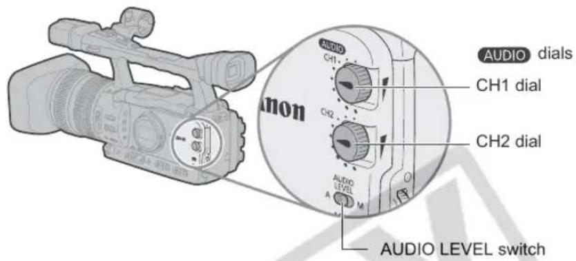
text_image
AUDIO dials CH1 dial CH2 dial AUDIO LEVEL switchHiding/Displaying the Audio Level Indicator
Open the menu and select [DISPLAY SETUP/®]. Select [AUDIO LEVEL], select a setting option and close the menu.
The audio level indicator can also be turned on/off with the custom key (☐ 70).
Automatic Audio Adjustments
Set the AUDIO LEVEL switch to A.

When recording audio using the built-in microphone with the AUDIO LEVEL switch set to A you can change the microphone's sensitivity (☐ 47).
Manual Audio Adjustments
- Set the AUDIO LEVEL switch to M.
- Turn the corresponding AUDIO dial (CH1 or CH2) to adjust each channel's audio level.

We recommend using headphones when adjusting the audio level. If the input level is too high, audio may become distorted even if the audio level indicator shows an appropriate level. Use commercially available headphones with a cable no longer than 3 m.
☐ You can select to synchronize the audio signal with the video signal by adding an equal amount of delay to the audio. Open the menu and select [AUDIO SETUP]. Select [AUD.M.SET], set it to [LINE OUT] and close the menu. If you wish to monitor audio in real time, select [NORMAL] instead. In either setting, the audio and video signals recorded on the tape will be synchronized.
XHG1 Embedded Audio
Embedded audio refers to the superimposing of the audio signal along with the video signal being output from the HD/SD SDI terminal.
MENU
(25)
SIGNAL SETUP SDI OUTPUT
··OFF
Open the menu and select [SIGNAL SETUP]. Select [SDI OUTPUT], set it to [ON] and close the menu.
- The embedded audio output will differ depending on the signal standard and the sampling frequency settings.
- Embedded audio is disabled if the tape is recorded with unlocked audio. ✉, ✉ 3/4 or ✉ 1/2 will appear on the screen.
CAMERA
| Signal Standard | Sampling Frequency | Locked/Unlocked Audio | Embedded Audio Output |
| HD | (48 kHz) | Locked | ● |
| SD | 32 kHz (12bit) | Locked | ●* |
| 48 kHz (16bit) | Locked | ● |
VCR/PLAY
| Signal Standard | Sampling Frequency | Locked/Unlocked Audio | Embedded Audio Output |
| HD | (48 kHz) | Locked | ● |
| SD | 32 kHz (12bit) | Locked | ●* |
| Unlocked | — | ||
| 48 kHz (16bit) | Locked | ● | |
| Unlocked | — |
* The sampling rate will be 48 kHz.
You can select to activate or turn off the image stabilizer depending on the recording conditions.

text_image
TAPE CARD EXT. CONT. VCR/ PLAY A Tv Av M
text_image
MENU (25) CAMERA SETUP IMG STAB ...ON (<Open the menu and select [CAMERA SETUP]. Select [IMG STAB], select a setting option and close the menu.
The image stabilizer cannot be turned off in the ☐ Easy Recording mode.

We recommend turning off the image stabilizer when mounting the camcorder on a tripod.
○ The image stabilizer is designed to compensate for a normal degree of camcorder shake.
☐ CAMERA·CARD: The image stabilizer will be activated while half-pressing the PHOTO button to lock the autofocus.

Programmed auto exposure modes provide advanced automated recording techniques ensuring professional results in various shooting conditions.
Selecting the Programmed AE Modes
Press the lock button and turn the POWER dial.
The symbol of the selected mode appears.
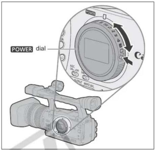
text_image
POWER dial AGC-UP ON+JAP GND OUTPUT WHITE BIL
Do not change the mode while recording as the brightness of the image may change abruptly.
☐ The ☐ Easy Recording, ⚠ Spotlight and ☑ Night modes are all-automatic modes. In the Ⓐ Auto, Tv Shutter-Priority, Av Aperture-Priority and M Manual modes you can manually change some settings to match the recording conditions.
□Easy Recording
The camcorder automatically controls the focus, shutter speed, aperture, gain, white balance, and AE Shift allowing you to simply point and film. This mode locks all of these features and options, making them fixed and unadjustable.
natural_image
Black-and-white photo of two sailboats on the ocean with a small boat visible in the distance (no text or symbols)A Auto
Like the Easy Recording mode, the camcorder automatically controls camera adjustments allowing you to simply point and film. However, in the Auto mode you have the option of adjusting the settings manually.

natural_image
Black-and-white photo of a family of four smiling outdoors with hills in the background (no text or symbols visible)Tv Shutter-Priority (55)
Use this mode to select the shutter speed. The camcorder automatically sets a matching aperture setting.
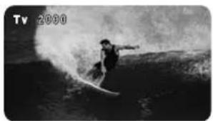
natural_image
Black-and-white photo of a person surfing on the ocean, no visible text or symbolsAv Aperture-Priority (56)
Use this mode to select between 7 aperture settings – from f/1.6 to f/9.5 (or to full iris close)– and the camcorder automatically sets a matching shutter speed. This mode allows for the best control of depth of field.
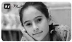
natural_image
Black-and-white portrait of a young woman with hand on cheek, no visible text or symbolsE
MManual (57)
This mode offers the creative freedom of a complete range of manual controls. In the Manual mode, you have the option to set the exposure at any combination of shutter speed and aperture levels.
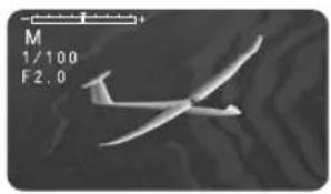
natural_image
Aircraft silhouette in flight against a dark background, with no visible text or symbols.Spotlight
The Spotlight mode automatically adjusts the exposure to effectively record images and/or subjects lit by a spotlight or other concentrated light source.
natural_image
Silhouette of two dancers in dynamic poses, one in black attire and the other in white, against a plain background (no text or symbols)Night
This mode allows you to continue recording even when light levels begin to fall. The camcorder uses lower shutter speeds (60i, 30F: 1/4–1/500; 24F: 1/3–1/500) to deliver proper exposure.
○Moving subjects may leave a trailing afterimage.
○Picture quality may not be as good as in other modes.
○White points may appear on the screen.
○Autofocus may not work as well as in other modes. In such case, adjust the focus manually.

natural_image
Black-and-white photo of two people in conversation, one wearing a head covering, with others in the background (no visible text or symbols)Availability of functions in each recording program
| Recording programs | ☐ | A | Tv | Av | M | ▲ | ▼ |
| EXP. LOCK button - - - - | ● | ||||||
| Iris ring -- | 1 | -1 | ● | ● | - | - | |
| SHUTTER dial -- | 1 | ● | -1 | ● | - | - | |
| AE shift adjustment | -(0) | ● | - | -(0) | -(0) | ||
| GAIN adjustment | -(AGC ON) | ● | -(0 dB) | -(AGC ON) | |||
| WHITE BALANCE adjustment | -(auto) | ● | |||||
| Custom preset adjustments | - | ● | |||||
| CUSTOM PRESET SELECT button | - | ● | |||||
| CUSTOM PRESET ON/OFF button | - | ● | |||||
| Skin detail | - | ● | |||||
| Clear Scan | - | - | ●2 | - | ●2 | - | - |
| Frequency selection of Clear Scan | - | - | ● | - | ● | - | - |
^1 Available when the exposure is locked.
^2 Available during clear scan.
Recording in the Shutter-Priority (Tv) Mode

text_image
SHUTTER dial POWER dialCAMERA
| 60i/30F | 1/4, 1/8, 1/15, 1/30, 1/60, 1/100, 1/250, 1/500, 1/1000, 1/2000, 1/4000, 1/8000, 1/15000, CS (clear scan) |
| 24F | 1/3, 1/6, 1/12, 1/24, 1/48, 1/60, 1/100, 1/250, 1/500, 1/1000, 1/2000, 1/4000, 1/8000, 1/15000, CS (clear scan) |
CAMERA·CARD
1/4, 1/8, 1/15, 1/30, 1/60, 1/100, 1/250, 1/500
| TAPE | CARD |
| EXT.CONT. | VCR/PLAY | A | Tv | Av | M |
1. Set the POWER dial to Tv.
2. Select the shutter speed with the SHUTTER dial.
With the customized functions (☐ 83) you can change the direction of the adjustment when you operate the SHUTTER dial.

○ Settings other than the shutter speed (aperture, etc.) are adjusted automatically.
○ The shutter speed changes when you lock and change the exposure.
When the AGC switch is set to ON, the numeric value flashes on the screen if the selected shutter speed is not suitable for the recording conditions. In such case, readjust the shutter speed. If you are using an ND filter, turn it off first and readjust the shutter speed.
○ The image quality may decrease to some extent when using slow shutter speeds.
When recording under artificial light sources such as fluorescent, mercury or halogen lamps, the screen may flicker depending on the shutter speed. To avoid the flicker, set the shutter speed to 1/100.
☐ You can use the custom keys (☐ 70) or the menu (☐ 128) to prevent the accidental operation of the SHUTTER dial.
Recording in the Aperture-Priority (Av) Mode
You can select an aperture value in the range F1.6 to F9.5 or CLOSE.
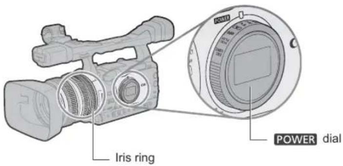
text_image
Iris ring POWER dial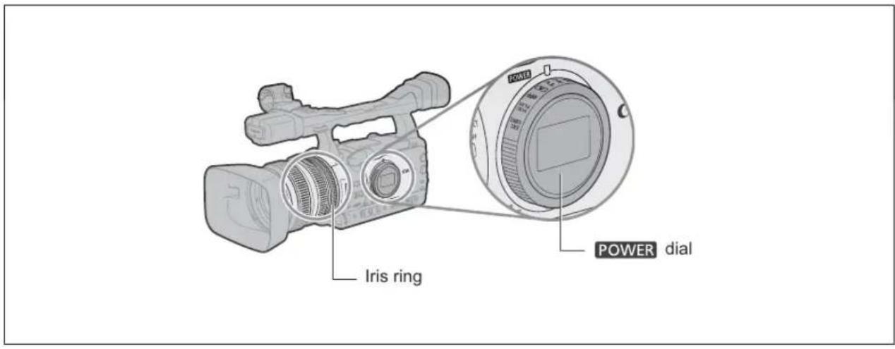
text_image
Iris ring POWER dial

text_image
EXT. CONT. VCR/ PLAY A Tv Av M □1. Set the POWER dial to Av.
2. Select the aperture with the Iris ring.
With the customized functions (☐ 83) you can change the direction of the adjustment when you turn the Iris ring.

○ Settings other than the aperture value (shutter speed, etc.) are adjusted automatically.
○ The aperture changes when you lock and change the exposure.
When the AGC switch is set to ON, the numeric value flashes on the screen when the selected aperture is not appropriate for the recording condition. In such case, readjust the aperture.
When the built-in ND filter is activated, the picture may become dark when you set a high aperture value. In such case, turn the ND Filter off first and readjust the aperture.
You can set the exposure at any combination of shutter speed and aperture.
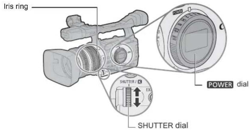
text_image
Iris ring SHUTTER / K EX SHUTTER dial POWER dialAvailable settings
| Shutter speed | CAMERA(60i/30F Frame rates) | 1/4, 1/8, 1/15, 1/30, 1/60, 1/75, 1/90, 1/100, 1/120, 1/150, 1/180, 1/210, 1/250, 1/300, 1/360, 1/420, 1/500, 1/600, 1/720, 1/840, 1/1000, 1/1200, 1/1400, 1/1700, 1/2000, 1/2300, 1/2600, 1/3000, 1/4000, 1/8000, 1/15000, CS (clear scan) |
| CAMERA(24F Frame rate) | 1/3, 1/6, 1/12, 1/24, 1/48, 1/60, 1/75, 1/90, 1/100, 1/120, 1/150, 1/180, 1/210, 1/250, 1/300, 1/360, 1/420, 1/500, 1/600, 1/600, 1/720, 1/840, 1/1000, 1/1200, 1/1400, 1/1700, 1/2000, 1/2300, 1/2600, 1/3000, 1/4000, 1/4000, 1/8000, 1/15000, CS (clear scan) | |
| CAMERA·CARD | 1/4, 1/8, 1/15, 1/30, 1/60, 1/75, 1/90, 1/100, 1/120, 1/150, 1/180, 1/210, 1/250, 1/300, 1/360, 1/360, 1/420, 1/500 | |
| Aperture | F1.6 - F9.5, CLOSE | |


text_image
EXT. CONT. VCR/ PLAY A Tv Av M □1. Set the POWER dial to M.
- The exposure indicator appears. Use the exposure indicator as an estimate.
- The ▼ mark above the indicator denotes the automatic exposure setting. The ■ mark of the indicator denotes the current exposure setting within ±2 stops (beyond 2 stops, the marker will blink).
2. Select the aperture with the Iris ring.
With the customized functions (☐ 83) you can change the direction of the adjustment when you turn the Iris ring.
3. Select the shutter speed with the SHUTTER dial.
With the customized functions (☐ 83) you can change the direction of the adjustment when you operate the SHUTTER dial.
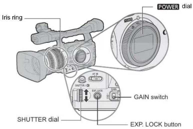
text_image
Iris ring POWER dial SHUTTER dial EXP. LOCK button GAIN switchExposure Lock
| TAPE | CARD |
| EXT.CONT. | VCR/PLAY | A | Tv | Av | M |
- Set the POWER dial to A, Tv or Av.
-
Press the EXP. LOCK button.
-
The exposure indicator appears. Use the exposure indicator as an estimate.
- The ▼ mark above the indicator denotes the automatic exposure setting. The ■ mark of the indicator denotes the current exposure setting within ± 2 stops (beyond 2 stops, the marker will blink).
- With the customized functions (☐ 83) you can also change the operation of the EXP.LOCK button (normal or long press).
You can use the AE Shift control to manually override the automatic exposure system in order to darken or lighten the image. Select from 15 AE levels (+2.0, +1.5, +1.25, +1.0, +0.75, +0.5, +0.25, ±0, -0.25, -0.5, -0.75, -1.0, -1.25, -1.5, -2.0).
E

text_image
TAPE CARD EXT. CONT. VCR/ PLAY A Tv Av M
text_image
MENU (25) CAMERA SETUP AE SHIFT...±0- Set the POWER dial to A, Tv or Av.
- Select the desired AE shift level: Open the menu and select [CAMERA SETUP]. Select [AE SHIFT], select a setting option and close the menu.
Adjusting the Gain
The gain control adjusts the level of the video signal generated depending on the lighting and shooting conditions. You can select from automatic gain control or of 3 preset gain levels (L: low, M: middle, H: high) to which you can independently assign gain values from -3 dB to +36 dB (CAMERA·8 dB (CAMERA·CARD)).
AGC switch set to ON: Automatic gain control.
AGC switch set to OFF: Manual gain level selection (L, M or H) with the GAIN switch.
Available gain levels that can be assigned to each GAIN switch position
| -3 dB | For the lowest noise recording for indoor, low light or low contrast scenes. |
| ±0 dB | For lifelike night scenes or scenes under artificial lighting. |
| 3 dB/6 dB/12 dB/18 dB/36 dB* | Increases the brightness in indoor or low-light scenes. Increases the depth of field. |
* CAMERA only.
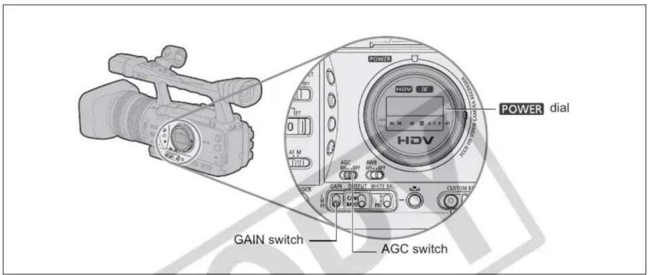
text_image
POWER dial AGC switch GAIN switch AGC switch
text_image
TAPE CARD EXT. CONT. VCR/ PLAY A Tv Av MAssigning Gain Values to the GAIN Switch Positions

flowchart
graph LR
    A["CAMERA SETUP"] --> B["GAIN SETTING"]
    B --> C["GAIN L...±0dB"]
    B --> D["GAIN M...6dB"]
    B --> E["GAIN H...12dB"]
- Set the POWER dial to A, Tv, Av or M.
- Open the menu and select [CAMERA SETUP]. Select the [GAIN SETTING] submenu and then one of the GAIN switch options.
[36dB] is available only in CAMERA mode.
- Select a setting option and press the SELECT/SET dial.
After the adjustment you will return to the [GAIN SETTING] submenu. Assign the gain values to the other GAIN switch options in the same way.
- Close the menu.
Selecting the Gain Level
- Set the POWER dial to A, Tv, Av or M.
- Set the AGC switch to OFF.
- Set the GAIN switch to the desired gain position.

When you select high gain values, the picture may flicker slightly. The [36dB] setting in particular allows you to film with a higher sensitivity but is more prone to the appearance of video noise and artifacts (white dots, vertical streaks or blocking).
Setting the White Balance
The camcorder uses an electronic white balance process to calibrate the picture for accurate color display under different lighting conditions.
In addition to the fully automated mode, white balance modes include an indoor mode, an outdoor mode, a color temperature setting and two user-defined custom preset values.
| Auto | Automated adjustment of white balance |
| ☀ (Outdoor) | Bright sunlight (5,600°K) |
| ☀ (Indoor) | Incandescent light (3,200°K) |
| K (Color temperature) | Setting depending on the hue of a specific lighting (2,800 - 12,000°K in 100°K increments) |
| Custom Preset A, B | Custom preset (3,200 - 5,600°K) |
| TAPE | CARD |
| EXT.CONT. | VCR/PLAY | A | Tv | Av | M |
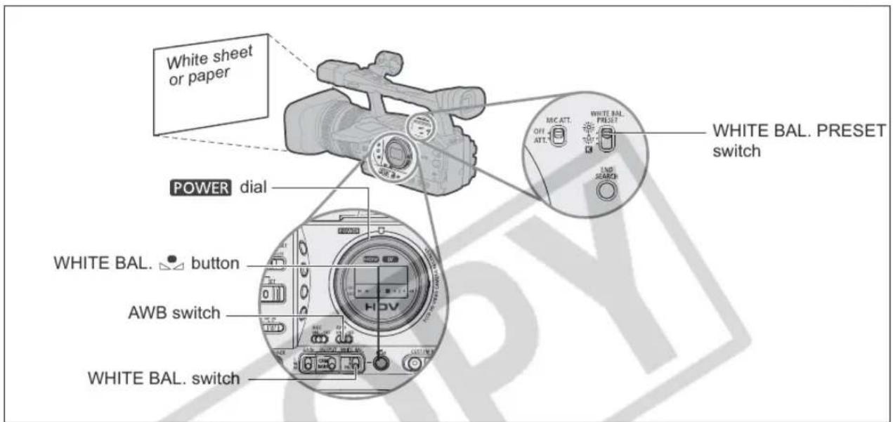
text_image
White sheet or paper POWER dial WHITE BAL. button AWB switch WHITE BAL. switch WHITE BAL. PRESET switch OFF ATT. MC ATT. OFF ATT. WHITE BAL. PRESET END SEARCHSelecting the Automatic White Balance
Set the AWB switch to ON.
Selecting One of the Preset Modes
- Set the POWER dial to a recording mode other than □.
- Set the AWB switch to OFF and the WHITE BAL. switch to PRE.
- Set the WHITE BAL. PRESET switch to ⚙ or ⚙.
You can also fine-tune the preset ⚙️/✿ settings. Press the WHITE BAL. 🔊 button so the preset icon starts flashing and the neutral value ±0 appears next to it. Adjust the white balance with the K dial to a value between -9 and +9 and press the WHITE BAL. 🔑 button again.
Setting the Color Temperature
- Set the P/EVEG a recording program other than .
- Set the AWB switch to OFF and the WHITE BAL. switch to PRE.
- Set the WHITE BAL. PRESET switch to K
The color temperature currently set will be displayed.
- Press the WHITE BAL. Button.
The color temperature display will start flashing.
-
Turn the Kial to set the desired color temperature.
-
Press the WHITE BAL. Button again.
The color temperature display stops flashing and stays on.
Setting a Custom White Balance
-
Set the radio to a recording program other than .
-
Set the AWB switch to OFF and the WHITE BAL. switch to one of the custom presets, A or B.
and the corresponding letter will flash on the screen.
- Point the camcorder at a white object and zoom in until it fills the whole screen.
Keep the camcorder zoomed at the white object until step 4 is completed.
- Press the WHITE BAL. □ button.
and the corresponding letter will stop flashing and stay on when the setting is completed.

When you set the custom white balance: Very rarely and depending on the light source, may keep flashing. The result will still be better than with the auto setting.
As long as the built-in rechargeable lithium battery is charged, the camcorder retains the custom white balance setting even if you turn it off.
The following custom preset settings take precedence, and will override the white balance set with the procedure above: The Color Matrix [CMX] setting, the 3 R/G/B Gain settings, and the 6 R/G/B Matrix settings (☐ 77).
○ The custom white balance may provide better results in the following cases:
- Changing lighting conditions
- Close-ups
- Subjects in a single color (sky, sea or forest)
- Under mercury lamps or certain types of fluorescent lights
○ Perform the custom white balance setting procedure in a sufficiently well lit place.
- Readjust the custom white balance if you turn the built-in ND filter on/off or when the light source has changed.
Recording with Preset Custom White Balance
- Set the POWER dial to a recording program other than □.
- Set the AWB switch to OFF and the WHITE BAL. switch to the desired custom preset, A or B.
The custom white balance is activated.
This camcorder has a zebra pattern feature that shows black and white diagonal stripes over the area that is overexposed. The zebra pattern is only displayed on the screen and will not affect your recordings. The zebra pattern will not be displayed while using the Peaking assist function (37).
Available zebra pattern settings: 70 IRE, 75 IRE, 80 IRE, 85 IRE, 90 IRE, 95 IRE, and 100 IRE.
| TAPE | CARD |
| EXT.CONT. | VCR/PLAY | A | Tv | Av | M |
Selecting the Zebra Pattern Level

text_image
MENU (25) DISPLAY SETUP/ ZEBRA LEVEL···85Open the menu and select [DISPLAY SETUP/☐]. Select [ZEBRA LEVEL], select a setting option and close the menu.
Activating the Zebra Pattern

text_image
MENU (25) DISPLAY SETUP/ ZEBRA·······OFFOpen the menu and select [DISPLAY SETUP/☐]. Select [ZEBRA], set it to [ON] and close the menu.

Using the Color Correction
With the color correction function you can set the camcorder to detect the characteristics of a certain color or pattern (color phase, chroma, area and Y level) and correct them automatically when recording. You can set the color correction for up to two different colors (A and B).
When determining the color to be corrected, the areas that will be corrected appear on the screen as a zebra pattern alternating with the normal picture. On a connected monitor or computer, those areas will appear instead as white areas alternating with the normal picture.

text_image
TAPE | CARD EXT. CONT. | VCR/ PLAY | A | Tv | Av | M | ↑ | ↺ | □Determining the Color to be Corrected
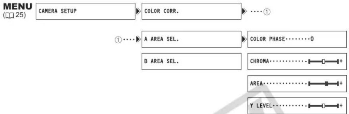
flowchart
graph LR
    A["CAMERA SETUP"] --> B["COLOR CORR."]
    B --> C["..."]
    D["A AREA SEL."] --> E["COLOR PHASE······O"]
    F["B AREA SEL."] --> G["CHROMA······I+"]
    H["AREA······I+"] --> I["AREA······I+"]
    J["Y LEVEL······I+"] --> K["..."]
- Open the menu and select [CAMERA SETUP]. Select the [COLOR CORR.] submenu and then select [A AREA SEL.] or [B AREA SEL.].
- Select each setting option, adjust the levels as necessary and close the menu.
[COLOR PHASE]: Select the basic color phase (0-15) of the color to be detected. Use the following values as an approximate reference: 0=purple, 3=red, 6=orange, 9=green, 12=blue.
[CHROMA]: Adjust the color saturation for the color to be detected. The more you adjust to [+] , the area detected will extend to include more vivid and richer colors.
[AREA]: Adjust the color range for the color to be detected. Adjusting to [+] detects a wider color range, and to [-] a narrower color range.
[Y LEVEL]: Adjust the brightness for the color to be detected. Adjusting to [+] detects brighter colors, and to [-] detects darker colors.
Adjusting the Color Correction
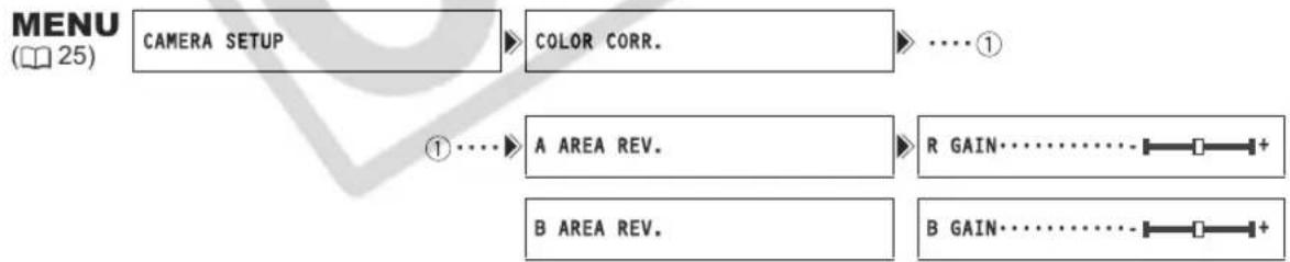
flowchart
graph LR
    A["CAMERA SETUP"] --> B["COLOR CORR."]
    B --> C["... ①"]
    D["A AREA REV."] --> E["R GAIN....+"]
    F["B AREA REV."] --> G["B GAIN....+"]
- Open the menu and select [CAMERA SETUP]. Select the [COLOR CORR.] submenu and then select [A AREA REV.] or [B AREA REV.].
- Select the color gain options, adjust the levels as necessary and close the menu.
[R GAIN]: Adjust the red gain of the detected area. Adjusting to [+] results in stronger red tones, and to [-] in stronger cyan tones.
[B GAIN]: Adjust the blue gain of the detected area. Adjusting to [+] results in stronger blue tones, and to [-] in stronger yellow tones.
Activating the Color Correction

flowchart
graph LR
    A["CAMERA SETUP COLOR CORR. CORRECT"] --> B["OFF"]
- Open the menu and select [CAMERA SETUP] and select the [COLOR CORR.] submenu.
- Select [CORRECT], select a correction mode other than [OFF] to correct only area A, only area B or both and then close the menu.

Using the Skin Detail Function
With the skin detail function, areas in the picture that have skin-tone characteristics will be detected, and the details in these areas will be softened in order to conceal skin imperfections. On the screen, those skin areas will be identified by a zebra pattern alternating with the normal picture (on a connected TV or computer screen they will appear in white instead).
You can adjust the hue, chroma, area and Y level as required, to determine the areas that will be detected as skin areas.

text_image
TAPE CARD EXT. CONT. VCR/ PLAY A Tv Av MActivating the Skin Detail Function

flowchart
graph LR
    A["CAMERA SETUP"] --> B["SKIN DETAIL"]
    B --> C["EFFECT LEVEL OFF"]
- Open the menu and select [CAMERA SETUP]. Select the [SKIN DETAIL] submenu and then select [EFFECT LEVEL].
- Select a setting option and close the menu.
" " appears.
Determining the Skin Area
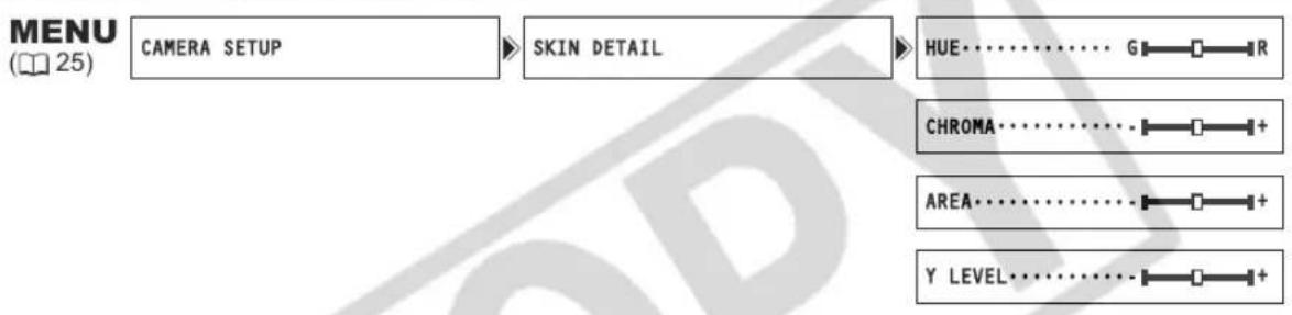
flowchart
graph LR
    A["CAMERA SETUP"] --> B["SKIN DETAIL"]
    B --> C["HUE: G R"]
    C --> D["CHROMA: +"]
    D --> E["AREA: +"]
    E --> F["Y LEVEL: +"]
- Open the menu, select [CAMERA SETUP] and then select the [SKIN DETAIL] submenu.
- Select each setting option, adjust the levels as necessary and press the SELECT/SET dial.
After the adjustment you will return to the [SKIN DETAIL] submenu. Adjust other setting options in the same way.
• [HUE]: Adjust the hue for detection of the skin area. Adjusting to [R] detects reddish skin color, and to [G] detects greenish skin color.
- [CHROMA]: Adjust the color saturation for detection of the skin area. Adjusting to [+] detects more vivid skin tones, and to [-] detects paler skin tones.
- [AREA]: Adjust the color range for detection of the skin area. Adjusting to [+] detects a wide color range, and to [-] detects a narrow color range.
- [Y LEVEL]: Adjust the brightness for detection of the skin area. Adjusting to [+] detects brighter skin color, and to [-] detects darker skin color.
- Close the menu.
With the sky detail function, blue sky areas in the picture will be detected and the detail level in these areas will be decreased to obtain a softer picture.

text_image
TAPE CARD EXT. CONT. VCR/ PLAY A Tv Av M MENU (25) CAMERA SETUP SKY DETAIL ....OFFTo activate the sky detail effect:
Open the menu and select [CAMERA SETUP]. Select [SKY DETAIL], set it to [SOFT ▲*] and close the menu.
Using the Clear Scan Function
This feature allows you to record a computer's CRT screen or other equipment without displaying black band or flicker on the screen. You can adjust the frequency from 60.1 Hz to 203.9 Hz.
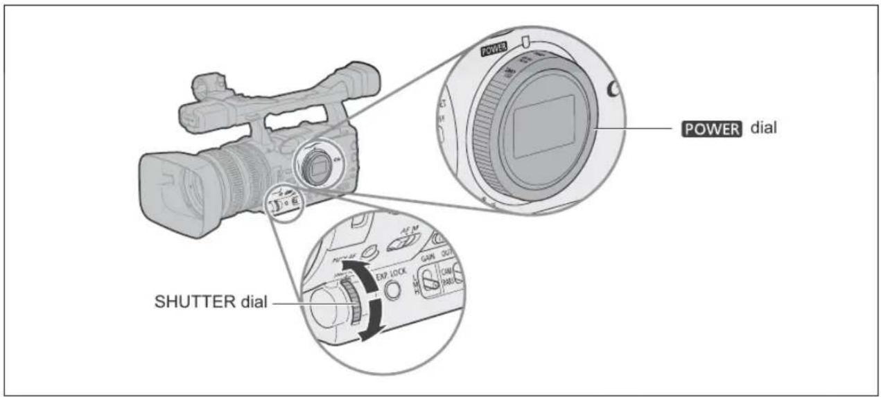
text_image
POWER dial SHUTTER dial
text_image
TAPE CARD EXT. CONT. VCR/ PLAY A Tv Av M
text_image
MENU (25) CAMERA SETUP CLEAR SCAN…60.1Hz- Set the POWER dial to Tv or M.
- Turn the SHUTTER dial to set the shutter speed to "CS".
- Open the menu and select [CAMERA SETUP]. Select [CLEAR SCAN], adjust the frequency and close the menu.
Adjust the frequency so that the black band does not appear.
You can assign frequently used functions to the custom keys. The custom keys can have different functions assigned to them in each of the operation modes.
Default settings:
| CAMERA | VCR/PLAY | CAMERA·CARD | VCR/PLAY·CARD | |
| CUSTOM KEY 1 TIME CODE TV SCREEN ZEBRA TV SCREEN | ||||
| CUSTOM KEY 2 | INDEX WRITE | DATA CODE | TV SCREEN | CVF+LCD BW |
The following functions can be assigned to the custom keys:
| CAMERA | VCR/PLAY | |
| Time codeIndex write ^2 Zebra patternVCR stop ^2 TV screen | Time code hold ^2 Audio levelCVF+LCD BWMAGN. buttonSHUTTER dialCP backward key ^1,2 | Time codeTV screenData codeAudio levelTime code hold ^2 CVF+LCD BW |
| CAMERA·CARD | VCR/PLAY·CARD | |
| Zebra patternTV screenCVF+LCD BWMAGN. buttonSHUTTER dialCP backward key ^1,2 | TV screenCVF+LCD BW | |
^1 Can only be assigned to Custom Key 2.
2 This function can only be operated with a custom key (Index write can also be operated with the wireless controller).

To check the current custom key settings:
In a recording mode: Open the menu and select [DISPLAY SETUP/☑]. Select [GUIDE INFO], set it to [CUSTOM KEYS] and close the menu.
In a playback mode: Open the menu and select [DISPLAY SETUP/☐]. Select [CUSTOM KEY], set it to [ON] and close the menu.
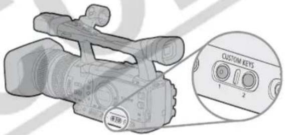
text_image
CUSTOM KEYS 1 2Changing the Custom Keys Setting

text_image
TAPE CARD EXT. CONT. VCR/ PLAY A Tv Av M MENU (25) SYSTEM SETUP/CUSTOM KEY 1 • INDEX WRITE** Default value in CAMERA
Open the menu and select [SYSTEM SETUP/ Select [CUSTOM KEY 1] or [CUSTOM KEY 2], select the function you wish to assign to the custom key and close the menu.
When you do not wish to use the custom keys, select [(NONE)].
Activating the Functions with the Custom Key
[TIME CODE] Time Code (42) CAMERA VCR/PLAY
Press the CUSTOM KEY (1 or 2) button.
The time code setting menu appears.
[INDEX WRITE] Index Write CAMERA
You can add an index signal to your recording for easy search in VCR/PLAY mode (102).
Press the CUSTOM KEY (1 or 2) button.
- The index signal will be recorded for approx. 6.5 seconds.
- When the camcorder is in record pause mode, the index signal will be written when you start recording.

An index signal cannot be added or erased later.
[ZEBRA] Zebra Pattern (64) CAMERA CAMERA·CARD
Press the CUSTOM KEY (1 or 2) button.
The zebra pattern is activated. Press the button again to deactivate it.
[VCR STOP] VCR Stop (☐ 28) CAMERA
When the camcorder is in record pause mode, you can turn off the recorder section. Even if [POWER SAVE] is set to [OFF], you can take your time adjusting the camera settings, while the recorder section of the camcorder is powered off so you do not need to worry about the tape or the video heads. VCR STOP can only be operated with the custom keys.
Press the CUSTOM KEY (1 or 2) button.
The VCR STOP mode is activated. Press the button again to return to record pause mode. You can also start recording by pressing the start/stop button directly in VCR STOP mode.
[TV SCREEN] TV Screen (90) CAMERA VCR/PLAY CAMERA·CARD VCR/PLAY·CARD
You can show the camcorder's displays on a connected TV.
Press the CUSTOM KEY (1 or 2) button.
[TC HOLD] Time Code Hold CAMERA VCR/PLAY
You can press the custom key button to freeze the display of the time code. The time code will continue running normally even while the time code display is on hold.
Time Code Hold can only be operated with the custom keys.
Press the CUSTOM KEY (1 or 2) button.
- Pressing the custom key button again will reactivate the normal display of the time code.
- While on hold, the time code will be displayed with an Next to it and "HOLD" will appear on the side panel display.
- The time code being output from the TIME CODE (XHG1 only), HD/SD SDI (XHG1 only), LANC and HDV/DV terminals will not be put on hold. The time code superimposed on the video signal output from the COMPONENT OUT terminal or the Video terminals will be put on hold.
- The time code hold will be canceled when you turn the camcorder on/off, change the operation mode between recording and playback or change the position of the / (card/tape) switch.
[AUDIO LEVEL] Audio Level Indicator (☐ 49) CAMERA VCR/PLAY
Press the CUSTOM KEY (1 or 2) button.
The audio level indicator appears. Press the button again to hide the audio level indicator.
[CVF+LCD BW] Viewfinder and LCD Screen's Black & White Display
The image on both, the viewfinder and the LCD screen, will be shown in black & white (on-screen displays and indicators will still be displayed in color). Press the button again to return to color display.
[MAGN.B.LOCK] MAGN. Button Lock CAMERA CAMERA·CARD
Press the CUSTOM KEY (1 or 2) button.
Pressing the button will lock the MAGN. buton to prevent its accidental operation. Press the custom key button again to reactivate the MAGN. button.
[SHTR D.LOCK] SHUTTER Dial Lock CAMERA CAMERA·CARD
Press the CUSTOM KEY (1 or 2) button.
Pressing the button will lock the SHUTTER dial to prevent its accidental operation. Press the button again to reactivate the SHUTTER dial.
[CP BKWD KEY] Custom Preset Backward Key CAMERA CAMERA·CARD
Press the CUSTOM KEY 2 button.
Usually, pressing the CUSTOM PRESET SELECT button will cycle forwards to the following custom preset file. Pressing the custom key button will instead cycle backwards to the preceding custom preset file.
Custom Preset Backward Key can only be operated with the custom keys.
[DATA CODE] Data Code (104) VCR/PLAY
Press the CUSTOM KEY (1 or 2) button.
The data code appears. Press the button again to hide the data code.
Recording Color Bars|Audio Reference Signal
You can generate and record color bars signals and a 1 kHz audio reference signal.
With the customized functions ([83) you can choose between SMPTE* standard-definition color bars ([TYPE 1]) and ARIB** multiformat HDTV color bars ([TYPE 2]) and you can also select the strength of the audio signal (-12 dB or -20 dB).
* Society of Motion Picture and Television Engineers.
** Association of Radio Industries and Businesses.
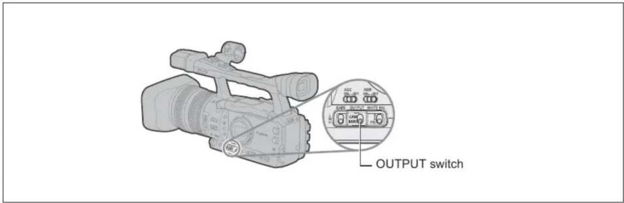
text_image
OUTPUT switch| TAPE | CARD | EXT.CONT. | VCR/PLAY | A | Tv | Av | M |
- Select the standard of the color bars signal [COLOR BARS] and the strength of the audio reference signal [1kHz TONE] with the customized functions (☐ 83).
- Set the OUTPUT switch to BARS.
- The color bars appear and the audio reference signal is emitted (if activated). Press the start/stop button to record the signal.
- If you set [1kHz TONE] to [OFF] the current audio input (microphone, line in, etc.) will be recorded as the audio signal.
This feature enables the camcorder to control the record and stop functions of an external digital device connected to the camcorder through the HDV/DV terminal. The device must comply with the IEEE1394 AV/C protocol. Use the optional CV-150F (4 pin-4 pin) or CV-250F (4 pin-6 pin) DV cable to connect the external device.
Windows XP (SP2) users can use the CONSOLE software (sold separately) to download video and audio recordings (in HDV or DV standards) from the camcorder to a computer's hard disk. For details refer to the software's help modules.

text_image
TAPE CARD EXT. VCR/ TV Av M CONT. CONT. PLAY A A MENU (25) SYSTEM SETUP/ DV CONTROL...OFF- Open the menu and select [SYSTEM SETUP/☑]. Select [DV CONTROL], set it to [ON DV] and close the menu.
- Press the start/stop button...
...when this camcorder is in record pause mode:
This camcorder: Recording
Connected device: Recording
...when this camcorder is recording:
This camcorder: Record pause mode
Connected device: Record pause mode
...when this camcorder is not ready for recording (no cassette loaded etc.)
Connected device: Recording/record pause mode
...after loading a cassette while the connected device is recording:
This camcorder: Recording
Connected device: Continues recording
Pressing the start/stop button again:
This camcorder: Record pause mode
Connected device: Record pause mode

While both this camcorder and a connected device are recording, if this camcorder stops recording because of a condition other than pressing the start/stop button (e.g., if the tape has reached its end), the connected device will continue recording.
When this camcorder stops recording you may notice a brief interruption of the audio on the connected device.
○ The status of the connected device is indicated as follows.
DVZ
Connected device is recording
DVZ
Connected device is in record pause or stop mode
DVZ→--
Connected device is in a mode other than record pause or stop
DVZ
[DV CONTROL] is set to [ON DV→], but no external device is connected
DVZ
Recording on the computer's hard disk
As long as the built-in rechargeable lithium battery is charged, the camcorder retains the DV control setting even if you turn the power off. Make sure to check the setting after using the DV control function, as the tape in the connected device may be overwritten.
When connecting two DV Control-compatible Canon camcorders with a DV cable, make sure to set [DV CONTROL] on the other connected camcorder to [OFF].
○ Up to 2 other devices can be connected to the XH G1/XH A1 for DV control.
With some non-Canon devices: The DV control may not work properly depending on the connected device.
SD Changing the Recording Mode (SP/LP)
When recording in Standard Definition (SD mode) only, you can choose between SP (standard play) and LP (long play). LP extends the tape usage by 1.5 times.

text_image
TAPE CARD EXT. VCR/ TV Av M CONT. CONT. PLAY A A MENU (25) RECORDING SETUP DV REC MODE·····SPTo change to LP mode, open the menu and select [RECORDING SETUP]. Select [DV REC MODE], set it to [LP] and close the menu.

Depending on the tape and its usage condition, the picture and sound recorded in LP mode may be distorted. We recommend using the SP mode for important recordings.

☐ If you record in both SP and LP modes on the same tape, the playback picture may become distorted, and the time code may not be written correctly.
○ If you play back a tape that has been recorded in LP mode with another digital device on this camcorder, or vice versa, the picture and sound may become distorted.
Changing the Display Language
The language used in the camcorder displays and menu items can be changed to German, Spanish, French, Italian, Polish, Russian, simplified Chinese or Japanese.

text_image
TAPE CARD EXT. CONT. VCR/ PLAY A Tv Av M MENU (25) DISPLAY SETUP/ LANGUAGE ...ENGLISHTo change the display language, open the menu and select [DISPLAY SETUP/☐]. Select [LANGUAGE☐], select a language and close the menu.

○ If you have mistakenly changed the language, follow the ☑ mark next to the menu item to change the setting.
The displays MENU and SET at the bottom of the screen refer to the names of buttons on the camcorder and will not change regardless of the language selected.
Changing the Date Format
You can select between three date formats. For example, [JAN. 1, 2006], [1. JAN. 2006] and [2006. 1. 1].

text_image
TAPE CARD EXT. CONT. VCR/ PLAY A Tv Av M MENU (25) SYSTEM SETUP/✓ D/TIME SET✓ DATE FORMAT .. JAN. 1,2006Open the menu and select [SYSTEM SETUP/☑]. Select the [D/TIME SET☑] submenu and then select [DATE FORMAT]. Select a date format and close the menu.
You can define preset levels for 23 recording specifications used when recording on tape (17 when recording still images on the memory card). Up to 9 custom preset files can be saved on the camcorder (custom preset files 7 - 9 are predefined files) and up to 20 on a memory card. Custom preset files can be copied from the camcorder to the memory card and vice versa. Also, the custom preset settings currently in effect can be embedded within a still image of the scene recorded on the memory card. This camcorder's custom preset files are not compatible with the XL H1's custom preset files.
Recording specifications that can be saved in a custom preset:
Gamma curve*, knee, black stretch/press, master pedestal*, setup level*, sharpness, horizontal detail frequency, horizontal/vertical detail balance, coring, NR1*, NR2*, color matrix*, color gain, color phase, R gain, G gain, B gain, R-G matrix, R-B matrix, G-R matrix, G-B matrix, B-R matrix and B-G matrix.
* Available only when recording on the tape.
[GAM] Gamma Curve CAMERA
You can select from [NORMAL], [CINE1] or [CINE2]. [NORMAL] corresponds to Video Gamma adjustments, while [CINE1] is a setting appropriate for video telecined from film and [CINE2] is a setting appropriate for transfer to film.
![CANON XH G1 - [GAM] Gamma Curve CAMERA - 1](/content/2026/05/768249/images/296e36c32dc8e4d3dbed5373c1ed63be8f80b3ae63efa0d2e545dcdbab943c94.jpg)
[KNE] Knee Point Adjustment
CAMERA CAMERA·CARD
Adjust the dynamic range (knee point) in the highlight area of the image to prevent overexposure. You can select from [AUTO], [HIGH], [MIDDLE] or [LOW].
[BLK] Black Stretch/Black Press
CAMERA CAMERA·CARD
Adjust the dynamic range in the black area of the image. You can select from [STRETCH], [MIDDLE] or [PRESS]. [STRETCH] emphasizes contrast in the dark area, while [PRESS] enhances or deepens darkness.
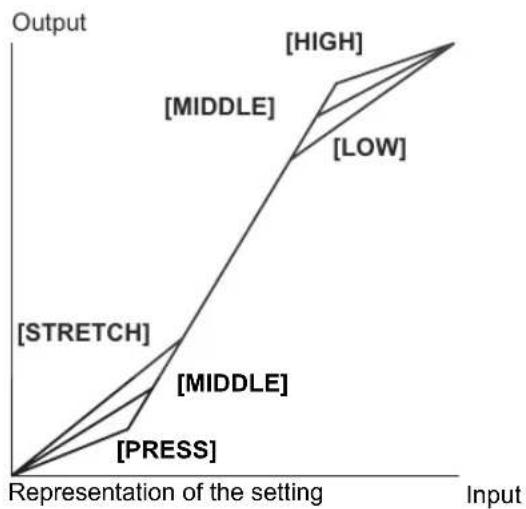
flowchart
graph TD
    A["Representation of the setting"] --> B["[MIDDLE"]]
    A --> C["[STRETCH"]]
    A --> D["[PRESS"]]
    B --> E["[HIGH"]]
    B --> F["[MIDDLE"]]
    B --> G["[LOW"]]
    C --> H["[MIDDLE"]]
    C --> I["[PRESS"]]
    D --> J["[HIGH"]]
    D --> K["[MIDDLE"]]
    D --> L["[LOW"]]
[PED] Master Pedestal CAMERA
Adjust the master pedestal level in the range -9 to +9.
[SET] Setup Level CAMERA
Adjust the setup level in the range -9 to +9.
- Depending on the value set for the master pedestal [PED], the setup level may not be able to take a negative value. In that case, adjusting the setup value within a certain value range will have no effect.
[SHP] Sharpness CAMERA CAMERA·CARD
Adjust the sharpness level in the range -9 to +9.
[HDF] Horizontal Detail Frequency CAMERA CAMERA·CARD
You can select from [HIGH], [MIDDLE] or [LOW].
[DHV] Horizontal/Vertical Detail Balance CAMERA CAMERA·CARD
Adjust the horizontal/vertical detail balance in the range -9 (only horizontal) to +9 (only vertical).
[COR] Coring CAMERA CAMERA·CARD
Adjust the detail noise level in the range -9 to +9.
[NR1] Noise Reduction 1 CAMERA
You can select from [OFF], [HIGH], [MIDDLE] or [LOW].
- With the [HIGH] setting moving subjects may leave a trailing afterimage.
- When picture noise is already low due to the gain settings, the noise reduction function may not be noticeable.
[NR2] Noise Reduction 2 CAMERA
Results in an effect similar to applying the skin detail function over the whole picture. You can select from [OFF], [HIGH], [MIDDLE] or [LOW].
- Unlike with the NR1 setting, a trailing afterimage will not appear.
[CMX] Color Matrix CAMERA
You can select from [NORMAL], [CINE1] or [CINE2].
[CGN] Color Gain CAMERA CAMERA·CARD
Adjust the color saturation level in the range -50 to +50.
[CPH] Color Phase CAMERA CAMERA·CARD
Adjust the color phase in the range -9 to +9.
[RGN] R Gain CAMERA CAMERA·CARD
Adjust the red level in the range -50 to +50.
[GGN] G Gain CAMERA CAMERA·CARD
Adjust the green level in the range -50 to +50.
[BGN] B Gain CAMERA CAMERA·CARD
Adjust the blue level in the range -50 to +50.
[RGM] R-G Matrix CAMERA CAMERA·CARD
Adjust the level in the range -50 to +50.
[ RBM] R-B Matrix CAMERA CAMERA·CARD
Adjust the level in the range -50 to +50.
[GRM] G-R Matrix CAMERA CAMERA·CARD
Adjust the level in the range -50 to +50.
[GBM] G-B Matrix CAMERA CAMERA·CARD
Adjust the level in the range -50 to +50.
[BRM] B-R Matrix CAMERA CAMERA·CARD
Adjust the level in the range -50 to +50.
[BGM] B-G Matrix CAMERA CAMERA·CARD
Adjust the level in the range -50 to +50.
![CANON XH G1 - [BGM] B-G Matrix CAMERA CAMERA·CARD - 1](/content/2026/05/768249/images/4d1bb9d760ab96e7fb2d33135dd3cf89b1bb1bafaf3b2f196fe890a0813ae197.jpg)
text_image
Enter the custom preset editing screen Save the custom preset file to the memory card Load a custom preset file from the memory card Back to the [CUSTOMIZE] submenu Select the custom preset file Change the custom preset settings Rename the custom preset file 1 PRESET_A File name of the currently selected custom preset file Overview of the contents of the custom preset file SELECT CP Back to the options on the left side bar Reset the custom preset to default values Protect the custom preset file![CANON XH G1 - [BGM] B-G Matrix CAMERA CAMERA·CARD - 2](/content/2026/05/768249/images/49a5ed832725cae43e81a05c7c67da80a6cd2a360dfc481b9e42a6e4331f43e1.jpg)
Changing the Custom Preset Settings
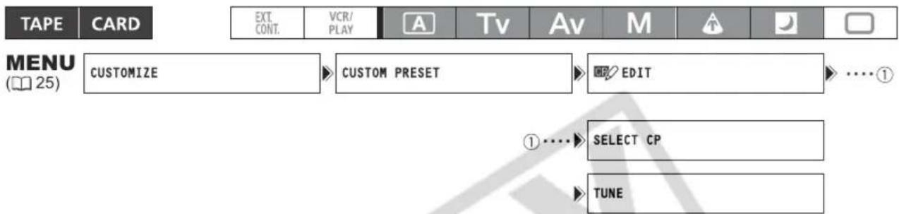
text_image
TAPE CARD EXT. CONT. VCR/ PLAY A Tv Av M MENU (25) CUSTOMIZE CUSTOM PRESET EDIT ....① ① .... SELECT CP TUNE- Open the menu, select [CUSTOMIZE] and then select the [CUSTOM PRESET] submenu.
The custom preset submenu appears.
- Select [CP EDIT] from the column on the left.
The cursor will move to the bottom bar of the custom preset editing screen. To return one level back to the options on the column on the left, select [RETURN] and press the SELECT/SET dial.
- From the bottom bar, select [CP SELECT CP] and then select the name of the custom preset file where you want to store the settings.
The current settings of the selected custom preset file will be shown in the custom preset item list.
- From the bottom bar, select [i++iTUNE].
The first item in the list will be highlighted in blue.
- From the list, select an item you want to adjust and press the SELECT/SET dial. Make the adjustment or the selection as necessary and press the SELECT/SET dial.
- During the adjustment you can verify the effect of each change on the screen.
- Repeat this step to adjust all the items you want to adjust.
- When you finish adjusting all the items in the custom preset, select [←RETURN], press the SELECT/SET dial and close the menu.

The custom preset items appear in one screen as 3-letter abbreviations followed by the current setting value. As you move between the items with the SELECT/SET dial, the full name of the currently selected item and its current value will be displayed at the bottom of the screen.
A protected custom preset file cannot be changed. If you attempt to change a protected file, o _m will start flashing.
Renaming a Custom Preset File
Follow steps 1-3 as described in Changing the Custom Preset Settings (79) to open the custom preset editing screen and select the custom preset file you want to rename.
1. From the bottom bar, select [RENAME].
The first character of the custom preset file name will start flashing.
2. Turn the SELECT/SET dial to select a number, letter or punctuation mark and press the dial.
- The next character of the custom preset file name will start flashing.
- Set the rest of the custom preset file name in the same way.
3. When you finish renaming the custom preset file, press the SELECT/SET dial.
You will return to the custom preset editing screen.
4. Close the menu.
Protecting a Custom Preset File
Follow steps 1-3 as described in Changing the Custom Preset Settings (☐ 79) to open the custom preset editing screen and select the custom preset file you want to protect.
1. From the bottom bar, select [O _n PROTECT].
- The protection mark O_n will appear next to the custom preset file name.
- To cancel the protection, repeat the procedure for a custom preset file with the ⚡ mark.
Resetting a Custom Preset File
Follow steps 1-3 as described in Changing the Custom Preset Settings (☐ 79) to open the custom preset editing screen and select the custom preset file you want to reset to default values.
1. From the bottom bar, select [i+RESET].
A confirmation screen will appear.
2. Select [EXECUTE] and press the SELECT/SET dial.
You will return to the custom preset editing screen.
3. Close the menu.

A protected custom preset file cannot be reset. If you attempt to reset a protected file, o= will start flashing.
Activating the Custom Preset Settings
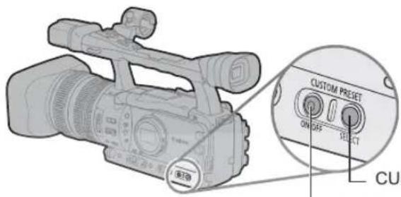
text_image
CUSTOM PREGET ON OFF SELECT CUSTOMCUSTOM PRESET SELECT button
CUSTOM PRESET ON/OFF button
TAPE
CARD
EXT. CONT.
VCR/PLAY
A
Tv
Av
M
T
[NO TEXT]
□
1. Press the CUSTOM PRESET SELECT button.
- Repeatedly pressing the button will cycle through the available custom preset files. You can also set a custom key as [CP BKWD KEY] to cycle through the options in reverse order (from last to first) (☐ 70).
- When you are not using the custom preset setting, set the camcorder to CP OFF.
2. Press the CUSTOM PRESET ON/OFF button.
The setting is activated.
Copying a Custom Preset File to the Memory Card
TAPE
CARD
EXT. CONT.
VCR/PLAY
A
Tv
Av
M
T
[NO TEXT]
□
- Open the menu, select [CUSTOMIZE] and then select the [CUSTOM PRESET] submenu.
- Select [ˈC] □ CAMERA → CARD] from the column on the left.
- From the bottom bar, select [SELECT CP] and then select the name of the custom preset file you want to copy to the card.
-
Select [SAVE POSITION] and select the filename under which you want to store the file on the memory card.
-
Up to 20 custom preset files can be stored on the memory card. If you try to save more than 20 custom preset filed one of the files on the card will be overwritten (you can select which file to overwrite).
-
If there are no custom preset files saved on the memory card, "NEW_FILE" will be used as the file name.
-
Select [→ □ EXECUTE] and in the confirmation screen select [EXECUTE] to copy the file.
-
Close the menu.
Loading a Custom Preset File from the Memory Card
TAPE
CARD
EXT. CONT.
VCR/PLAY
A
Tv
Av
M
T
[NO TEXT]
□
- Open the menu, select [CUSTOMIZE] and then select the [CUSTOM PRESET] submenu.
- Select [CARD CAMERA] from the column on the left.
- From the bottom bar, select [IMPORT] and then select the name of the custom preset file you want to load to the camcorder.
-
Select [ SELECT POSITION] and select the preset number under which you want to store the file in the camcorder.
-
Select [ EXECUTE] and in the confirmation screen select [EXECUTE] to load the file.
- Close the menu.
Loading a Custom Preset File from a Still Image to the Camcorder
With the customized functions (83) you can select to save the custom preset settings currently in use along with a still image of the recording in omecha. This is very useful when you want to load the custom preset file later by selecting the still image captured from a specific scene.
| TAPE | CARD |
| EXT.CONT. | VCR/PLAY | A | Tv | Av | M |
- Select the still image that contains the custom preset file you want to load. Use the CARD + / - buttons to move between the still images.
- Open the menu, select [CUSTOMIZE] and then select [META DATA CP].
- Select [☐→CARD → CAMERA] from the column on the left.
- From the bottom bar, select [☐] SELECT POSITION] and select the preset number under which you want to store the file on the camcorder.
- Select [→□EXECUTE] and in the confirmation screen select [EXECUTE] to load the file.
- Close the menu.

Custom preset files 7 to 9 are predefined settings designed for specific scenes.
- These 3 custom preset files are protected and, as long as the protection is not removed, cannot be overwritten.
- Even if you deleted or changed the sample custom preset files, you can reset them to the original values by resetting all the camcorder's settings. Open the menu and select [SYSTEM SETUP/√]. Select [RESET ALL] and select [YES] in the confirmation screen.
- After resetting custom preset files 1 to 6 with the [iːɪə] RESET] option, they will all contain the same settings.
| Custom Preset [7 VIDEO.C] | For playback on a consumer-level monitor.[BLK] = [PRESS], [PED] = -2, [SET] = -2 |
| Custom Preset [8 CINE.V] | For playback on a monitor TV with a film-like feel.[GAM] = [CINE1], [KNE] = [LOW], [BLK] = [STRETCH], [SHP] = -4,[CMX] = [CINE1], [CGN] = -20, [CPH] = 5, [RBM] = -5, [GRM] = -5[GBM] = -5, [BRM] = 5, [RGM] = 12 |
| Custom Preset [9 CINE.F] | For video transfer to film.[GAM] = [CINE2], [KNE] = [LOW], [BLK] = [STRETCH], [SHP] = 6,[CMX] = [CINE2], [RGN] = -8 |
* All other settings are left at their neutral values.
Using the Customized Functions
You can customize to your personal preferences many aspects of the operation of the camcorder, most of them governing how the camcorder operates in CMOERA. You can adjust up to 3 different custom function files and save them on the camcorder or to a memory card. By just reading the custom function file saved on the memory card with another XH G1/XH A1, you will instantly get a camcorder configured to operate in the same familiar manner you prefer.
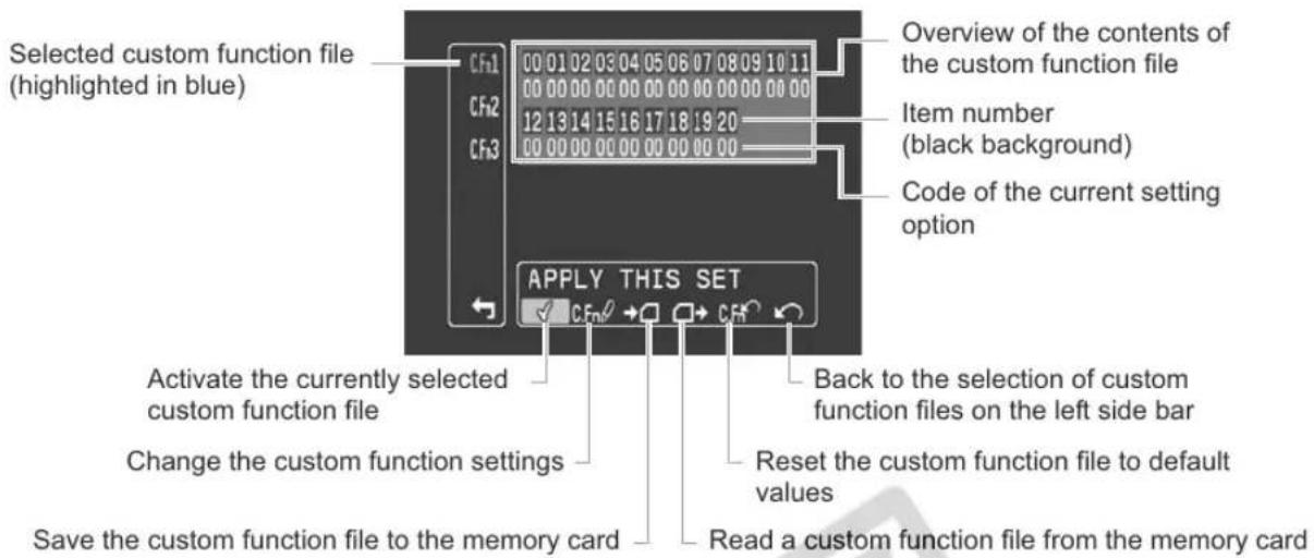
text_image
Selected custom function file (highlighted in blue) CF1 00 01 02 03 04 05 06 07 08 09 10 11 CF2 00 00 00 00 00 00 00 00 00 00 00 CF3 12 13 14 15 16 17 18 19 20 00 00 00 00 00 00 00 00 00 Overview of the contents of the custom function file Item number (black background) Code of the current setting option Apply THIS SET Activate the currently selected custom function file Change the custom function settings Save the custom function file to the memory card Back to the selection of custom function files on the left side bar Reset the custom function file to default values Read a custom function file from the memory cardChanging the Custom Function Settings
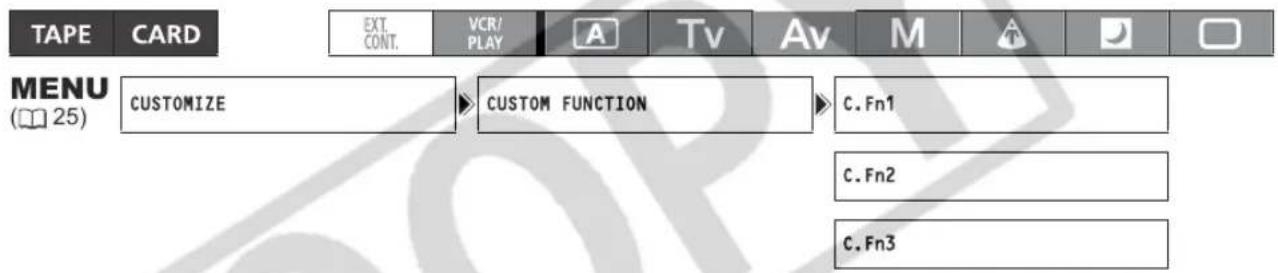
text_image
TAPE CARD EXT. CONT. VCR/ PLAY A Tsv Av M MENU (25) CUSTOMIZE CUSTOM FUNCTION C.Fn1 C.Fn2 C.Fn3- Open the menu, select [CUSTOMIZE] and then select the [CUSTOM FUNCTION] submenu.
The custom function editing screen appears.
- From the column on the left, select one of the 3 custom function files [C.Fn1] - [C.Fn3].
The current settings of the selected custom function file will be shown in the custom function item list. The cursor will move to the bottom bar of the custom function editing screen. To return one level back to the options on the column on the left, select [RETURN] and press the SELECT/SET dial.
- From the bottom bar, select [C.Fn∅ TUNE].
The first item in the list will be highlighted in blue.
- From the list, select an item you want to adjust and press the SELECT/SET dial. Make the selection as necessary and press the SELECT/SET dial.
Repeat this step to adjust all the items you want to adjust.
- When you finish adjusting all the items in the custom function file, select [RETURN], press the SELECT/SET dial and close the menu.

The custom function items appear in one screen represented only by the item number on the top (numbers 00 - 20 with a black background), and the code of the current setting immediately under it.
Resetting a Custom Function File
- Open the menu, select [CUSTOMIZE] and then select the [CUSTOM FUNCTION] submenu.
- From the column on the left select the custom function file you want to reset.
- From the bottom bar select [RESET].
- Select [OK], press the SELECT/SET dial and close the menu.
Activating a Custom Function File
Even if you define a custom function file, as long as you do not activate it the camcorder will function according to its default settings.
- Open the menu, select [CUSTOMIZE] and then select the [CUSTOM FUNCTION] submenu.
- From the column on the left select the custom function file you want to activate.
- From the bottom bar select [√ APPLY THIS SET].
- Select [ACTIVE] and press the SELECT/SET dial √ will appear next to the custom function file currently activated.
Copying a Custom Function File to the Memory Card
- Open the menu, select [CUSTOMIZE] and then select the [CUSTOM FUNCTION] submenu.
- From the column on the left select the custom function file you want to copy to the memory card.
- From the bottom bar select [→☐ SAVE TO CARD].
- Select the destination file on the memory card [→□ 1] - [→□ 3].
- Select [OK], press the SELECT/SET dial and close the menu. When the operation is finished, "TASK COMPLETED" will appear on the screen.
Loading a Custom Function File from the Memory Card
- Open the menu, select [CUSTOMIZE] and then select the [CUSTOM FUNCTION] submenu.
- From the column on the left select the custom function file to which you want to load the settings from the memory card.
- From the bottom bar select [☐→READ FROM CARD].
- Select the source file on the memory card [→□ 1] - [→□ 3].
- Select [OK], press the SELECT/SET dial and close the menu.
When the operation is finished, "TASK COMPLETED" will appear on the screen.
CAMERA Availability of custom functions in each recording program/playback mode
| Custom Function | ☐ | A | Tv | Av | M | A | D | VOLU PLAY | ||
| 00 SHCKLSS WB/GN WHITE BALANCE - | (OFF) | ● | ● | ● | ● | - (OFF) | - (OFF) | - | ||
| GAIN - | (OFF) | ● | ● | ● | ● | ● | - | |||
| 01 AE RESPONSE - | (MID) | ● | ● | ● | ● | - (MID) | - (MID) | - | ||
| 02 HIGH-SPEED ZOOM - | (OFF) | ● | ● | ● | ● | ● | ● | - | ||
| 03 | FOCUS RING CTRL | ● | - | |||||||
| 04 | BUTTONS OPER. | MAGN. | - | ● | - | |||||
| WB SET | - | ● | - | |||||||
| EXP.LOCK | - | ● | ● | ● | - | - | - | - | ||
| PUSH AF | ● | - | ||||||||
| 05 | RINGS DIRECTION | ZOOM | ● | - | ||||||
| FOCUS | ● | - | ||||||||
| IRIS | - | ●1 | ●1 | ● | ● | - | - | - | ||
| 06 | DIALS DIRECTION | CURSOR | ● | ● | ||||||
| SHUTTER | - | ●1 | ● | ●1 | ● | - | - | - | ||
| 07 | FOCUS PRIORITY | - (OFF) | - | |||||||
| 08 | SIMULT.IMG.REC | - (ON) | ● | - | ||||||
| 09 | MARKER LEVEL | MARKER | ● | - | ||||||
| ASPECT | ● | - | ||||||||
| SAFETY | ● | - | ||||||||
| 10 | FAST BW-MOD | MAGN. | - | ● | - | |||||
| PEAKING | - | ● | - | |||||||
| 11 | OBJ DST UNIT | - | ● | - | ||||||
| 12 | ZOOM INDICATOR | ● | - | |||||||
| 13 | COLOR BARS | ● | - | |||||||
| 14 | 1kHz TONE | ● | - | |||||||
| 15 | WIRELESS REMOTE | ● | ● | |||||||
| 16 | POWER SAVE | ●2 | - (OFF) | |||||||
| 17 | TALLY LAMP | ●3 | ●3 | |||||||
| 18 | LED | ● | ● | |||||||
| 19 | BEEP | ● | ● | |||||||
| 20 | CHARACTER REC | ● | - | |||||||
^1 Only during exposure lock.
2 Only when using a battery pack. When the power adapter is connected, the function will be set to [OFF].
^3 Only when [LED] is set to a setting other than [OFF]. When [LED] is set to [OFF], this function will be set to [OFF] as well.
CAMERA·CARD Availability of custom functions in each recording program/playback mode
| Custom Function | ☐ | A | Tv | Av | M | ▲ | ▼ | VCCU PLAY | ||
| 00 SHCKLSS WB/GN WHITE BALANCE - | (OFF) | - | ||||||||
| GAIN - | (OFF) | - | ||||||||
| 01 AE RESPONSE - | (MID) | - | ||||||||
| 02 HIGH-SPEED ZOOM - | (ON) | - | ||||||||
| 03 | FOCUS RING CTRL | ● | - | |||||||
| 04 | BUTTONS OPER. | MAGN. | - | - | ||||||
| WB SET | - | - | ||||||||
| EXP.LOCK | - | ● | ● | ● | - | - | - | - | ||
| PUSH AF | - | |||||||||
| 05 | RINGS DIRECTION | ZOOM | - | |||||||
| FOCUS | - | |||||||||
| IRIS | - | ●1 | ●1 | ● | ● | - | - | - | ||
| 06 | DIALS DIRECTION | CURSOR | ● | |||||||
| SHUTTER | - | ●1 | ● | ●1 | ● | - | - | - | ||
| 07 | FOCUS PRIORITY | -(ON) | - | |||||||
| 08 | SIMULT.IMG.REC | - | - | |||||||
| 09 | MARKER LEVEL | MARKER | - | |||||||
| ASPECT | - | |||||||||
| SAFETY | - | |||||||||
| 10 | FAST BW-MOD | MAGN. | - | - | ||||||
| PEAKING | - | - | ||||||||
| 11 | OBJ DST UNIT | - | - | |||||||
| 12 | ZOOM INDICATOR | - | ||||||||
| 13 | COLOR BARS | - | ||||||||
| 14 | 1kHz TONE | - | ||||||||
| 15 | WIRELESS REMOTE | ● | ||||||||
| 16 | POWER SAVE | -(OFF) | ||||||||
| 17 | TALLY LAMP | - | ||||||||
| 18 | LED | ● | ||||||||
| 19 | BEEP | ● | ||||||||
| 20 | CHARACTER REC | - | ||||||||
^1 Only during exposure lock.
2 Only when using a battery pack. When the power adapter is connected, the function will be set to [OFF].
Custom Function Items List
The default value for all items is the option assigned to 00.
00 [SHCKLSS WB/GN] Shockless White Balance/Gain CAMERA
The shockless setting will ensure a softer transition when changing the white balance or gain.
CAMERA mode: The shockless gain will not function when changing the gain setting from/to -3 dB or +36 dB.
| Setting Options | Shockless white balance | Shockless gain |
| 00 | OFF | OFF |
| 01 | ON | |
| 02 | OFF | ON |
| 03 | ON |
01 AE Response [AE RESPONSE] CAMERA
Selects the camcorder's response when you change the automatic exposure setting.
Setting Options: 00 - MIDDLE, 01 - HIGH, 02 - LOW.
02 [HIGH-SPEED ZOOM] High-speed Zoom CAMERA
In CAMERA, makes the zoom operation at the constant zoom speeds 14 - 16 even faster (in
CAMERA·CARD mode the default is [ON] and cannot be changed).
- When set to [ON], if you operate the zoom ring very quickly the zoom response may lag slightly.
- At the fastest zoom speed settings the autofocus may not work correctly.
Setting Options: 00 - OFF, 01 - ON.
03 [FOCUS RING CTRL] Focus Ring Control CAMERA CAMERA·CARD
Selects the sensitivity of the response when operating the FOCUS ring.
Setting Options: 00 - NORMAL, 01 - SLOW.
04 [BUTTONS OPER.] Buttons Operation CAMERA CAMERA·CARD
Changes the length of pressing various buttons to prevent their accidental operation. When you select [LONG PUSH], keep the button pressed for more than 1 second.
| Setting Options | MAGN. button | WHITE BAL. ▲ button | EXP. LOCK button | PUSH AF button |
| 00 | ONE PUSH | ONE PUSH | ONE PUSH | ONE PUSH |
| 01 | LONG PUSH | |||
| 02 | ONE PUSH | LONG PUSH | ||
| 03 | LONG PUSH | |||
| 04 | ONE PUSH | ONE PUSH | LONG PUSH | |
| 05 | LONG PUSH | |||
| 06 | ONE PUSH | LONG PUSH | ||
| 07 | LONG PUSH | |||
| 08 | ONE PUSH | ONE PUSH | ONE PUSH | LONG PUSH |
| 09 | LONG PUSH | |||
| 10 | ONE PUSH | LONG PUSH | ||
| 11 | LONG PUSH | |||
| 12 | ONE PUSH | ONE PUSH | LONG PUSH | |
| 13 | LONG PUSH | |||
| 14 | ONE PUSH | LONG PUSH | ||
| 15 | LONG PUSH |
05 [RINGS DIRECTION] Rings Direction CAMERA CAMERA·CARD
Changes the direction of the adjustment when turning the camcorder's rings.
Zoom ring: NORMAL – turn up for wide angle W, REVERSE – turn down for wide angle W.
Focus ring: NORMAL – turn up to focus closer, REVERSE – turn down to focus closer.
Iris ring: NORMAL – turn up to close, REVERSE – turn down to close.
| Setting Options | Zoom ring | Focus ring | Iris ring |
| 00 | NORMAL | NORMAL | NORMAL |
| 01 | REVERSE | ||
| 02 | NORMAL | REVERSE | |
| 03 | REVERSE | ||
| 04 | NORMAL | NORMAL | REVERSE |
| 05 | REVERSE | ||
| 06 | NORMAL | REVERSE | |
| 07 | REVERSE |
06 [DIALS DIRECTION] Dials Direction CAMERA CAMERA·CARD
Changes the direction of the adjustment when operating the shutter dial and the SELECT/SET dial when it serves as a cursor (for example, while selecting setting options in the menu screens or in the index screen). SELECT/SET dial ([CURSOR]): NORMAL – turn up to move left, REVERSE – turn down to move left.
SHUTTER dial: NORMAL – turn up for a faster shutter speed, REVERSE – turn down for a faster shutter speed.
| Setting Options SELECT/SET dial ([CURSOR]) SHUTTER dial | ||
| 00 | NORMAL | NORMAL |
| 01 | REVERSE | |
| 02 | NORMAL | REVERSE |
| 03 | REVERSE | |
07 [FOCUS PRIORITY] Focus Priority CAMERA·CARD
When set to [ON], when you press the PHOTO button in CAMERA·CARD mode a still image will be recorded only after the autofocus has been adjusted. When set to [OFF] the still image will be recorded as soon as you press the PHOTO button.
Setting Options: 00 - ON, 01 - OFF.
08 [SIMULT.IMG.REC] Simultaneous Recording of a Still Image CAMERA CAMERA·CARD
Selects whether you can record a still image on the memory card while recording on the tape. When set to [ON+CP DATA] the custom preset settings currently in use will be recorded along with the still image. Setting Options: 00 - OFF, 01 - ON, 02 - ON+CP DATA.
09 [MARKER LEVEL] Markers' Intensity Level CAMERA CAMERA·CARD
Selects the intensity of the markers displayed on the screen between 40% (gray) and 100% (white).
| Setting Options | Level/Center/Grid markers | Aspect ratio guides | Safety zone guides |
| 00 | 100% | 100% | 100% |
| 01 | 40% | ||
| 02 | 100% | 40% | |
| 03 | 40% | ||
| 04 | 100% | 100% | 40% |
| 05 | 40% | ||
| 06 | 100% | 40% | |
| 07 | 40% |
10 [F.AST BW-MOD] Focus Assist Function B&W Display Mode CAMERA CAMERA·CARD
Changes the display mode to black & white while the focus assist functions are activated.
| Setting Options | Magnifying | Peaking |
| 00 | OFF | OFF |
| 01 | ON | |
| 02 | OFF | ON |
| 03 | ON |
11 [OBJ DST UNIT] Object Distance Units Display CAMERA CAMERA·CARD
Selects the units for the display of the distance to the object between meters and feet.
Setting Options: 00 - m (meter), 01 - ft (feet).
12 [ZOOM INDICATOR] Zoom Indicator Display CAMERA CAMERA·CARD
Selects the display of the zoom indicator between a graphic bar and a numeric display.
Setting Options: 00 - BAR, 01 - NUMBER.
13 [COLOR BARS] Color Bars Signal CAMERA CAMERA·CARD
Selects the type of signal to use to produce the color bars: SMPTE color bars (type 1) or ARIB color bars (type 2).
Setting Options: 00 - TYPE 1, 01 - TYPE 2.
14 [1kHz TONE] 1 kHz Reference Audio Signal CAMERA CAMERA·CARD
Selects the strength of the audio signal.
Setting Options: 00 - OFF, 01 - -12dB, 02 - -20dB.
15 [WIRELESS REMOTE] Wireless Remote Controller CAMERA CAMERA·CARD
Selects the remote sensor mode that the camcorder will accept. When set to [OFF (☑)] the camcorder will not accept commands from wireless controllers.
Setting Options: 00 - 1, 01 - 2, 02 OFF .
16 [POWER SAVE] Power Save Mode CAMERA CAMERA·CARD
Activates the power save function so the camcorder automatically shuts off when powered by a battery and left without operation for approximately 5 minutes.
Setting Options: 00 - ON, 01 - OFF.
17 [TALLY LAMP] Tally Lamp CAMERA CAMERA·CARD
Selects the operation of the tally lamp. Even if set to [OFF], the tally lamp will turn on when receiving a command from the wireless controller.
Setting Options: 00 - ON, 01 - BLINK, 02 - OFF.
18 [LED] LED Indicators CAMERA CAMERA·CARD
Selects the operation of the LED indicators on the camcorder. When set to type 1 all LED indicators will be on, except for that of the HDV/DV terminal. When set to type 2, all LED indicators (including that of the HDV/DV terminal) will be on.
Setting Options: 00 - TYPE 1, 01 - TYPE 2, 02 - OFF.
19 [BEEP] Beep CAMERA CAMERA·CARD
Selects the volume for the camcorder's operations and warning beeps.
Setting Options: 00 - OFF, 01 - LOW VOLUME, 02 - HIGH VOLUME.
20 [CHARACTER REC] Superimposing Character Recording CAMERA CAMERA·CARD
Selects whether to embed the on-screen character displays (date and time) as part of the video recording. When set to [ON], the menu option [TV SCREEN] will not be available and [COMP.OUT] will automatically be set to [1080i/480i] and you will not be able to select [480i].
Setting Options: 00 - OFF, 01 - ON.
Hiding/Showing the Displays on the TV Screen
When you connect a TV for recording, you can select to hide the camcorder displays on the TV screen. For playback, you can show the camcorder displays on the TV screen.
To activate the on-screen displays at the level that you customized, repeatedly press the DISP. button (29).

text_image
TAPE CARD EXT. CONT. VCR/ PLAY A Tv Av M MENU (25) DISPLAY SETUP/ TV SCREEN···ON** In recording mode. The default value in playback modes is [OFF].
Open the menu and select [DISPLAY SETUP/∅]. Select [TV SCREEN], set it to [ON] or [OFF] and close the menu.
The displays appear on or disappear from the TV screen, according to the setting selected.
Customizing the On-Screen Displays
You can customize which icons to display on the screen according to your personal preferences and needs. You can save your personal settings as a custom display file on the camcorder or on the memory card.
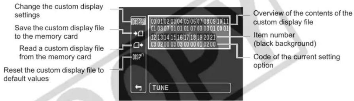
text_image
Change the custom display settings Save the custom display file to the memory card Read a custom display file from the memory card Reset the custom display file to default values DISP 00 01 02 03 04 05 06 07 08 09 10 11 01 03 07 01 01 01 07 03 03 01 00 01 12 13 14 15 16 17 18 19 20 21 03 02 00 03 03 00 00 01 02 00 TUNE Overview of the contents of the custom display file Item number (black background) Code of the current setting optionChanging the Custom Display Settings

text_image
TAPE CARD EXT. VCR/ TV Av M CONT. CONT. PLAY A Play MENU CUSTOMIZE CUSTOM DISPLAY (25)- Open the menu, select [CUSTOMIZE] and then select [CUSTOM DISPLAY].
The custom display editing screen appears.
The current settings of the selected custom display file will be shown in the custom display item list.
- From the column on the left, select [DISP∅ TUNE].
The first item in the list will be highlighted in blue.
- From the list, select an item you want to adjust and press the SELECT/SET dial. Make the selection as necessary and press the SELECT/SET dial.
Repeat this step to adjust all the items you want to adjust.
-
When you finish adjusting all the items in the custom display file, select [RETURN], press the SELECT/SET dial and close the menu.
-
Repeatedly press the DISP. button to select the display level you customized.

The custom display items appear in one screen represented only by the item number on the top (numbers 00 - 21 with a black background), and the code of the current setting immediately under it.
Resetting a Custom Display File
- Open the menu, select [CUSTOMIZE] and then select [CUSTOM DISPLAY].
- From the column on the left select [RESET].
- Select [OK], press the SELECT/SET dial and close the menu.
Copying a Custom Display File to the Memory Card
- Open the menu, select [CUSTOMIZE] and then select [CUSTOM DISPLAY].
- From the column on the left select [→□SAVE TO CARD].
- Select [OK], press the SELECT/SET dial and close the menu.
Loading a Custom Display File from the Memory Card
- Open the menu, select [CUSTOMIZE] and then select [CUSTOM DISPLAY].
- From the column on the left select [☐→READ FROM CARD].
- Select [OK], press the SELECT/SET dial and close the menu.
Custom Display Items List
The default value for all items is the option assigned to 00.
00 [REC PROGRAMS] Recording Mode Icon CAMERA CAMERA CARD
Setting Options: 00 - OFF, 01 - ON.
01 [CAMERA DATA1] Camera Data (1/2) CAMERA CAMERA·CARD
| Setting Options | Aperture value | Shutter speed value |
| 00 | OFF | OFF |
| 01 | ON | |
| 02 | OFF | ON |
| 03 | ON |
02 [CAMERA DATA2] Camera Data (2/2) CAMERA CAMERA·CARD
| Setting Options | Exposure display | White Balance display | Gain selection display |
| 00 | OFF | OFF | OFF |
| 01 | ON | ||
| 02 | OFF | ON | |
| 03 | ON | ||
| 04 | OFF | OFF | ON |
| 05 | ON | ||
| 06 | OFF | ON | |
| 07 | ON |
03 [ZOOM] Zoom Indicator CAMERA CAMERA·CARD
You can select to display the zoom indicator permanently or only when operating the zoom. Setting Options: 00 - OFF, 01 - ON(NORMAL), 02 - ON(ALWAYS).
04 [FOCUS] Focus Distance Display CAMERA CAMERA·CARD
You can select to display the focus distance indication permanently or only when operating the focus. Setting Options: 00 - OFF, 01 - ON(NORMAL), 02 - ON(ALWAYS)
05 [ND] ND Filter displays CAMERA
Setting Options: 00 - OFF, 01 - ON.
06 [IMAGE EFFECTS] Image Effects CAMERA CAMERA·CARD
| Setting Options S | kin detail Sky detail | Color correction | |
| 00 OFF OFF OFF | |||
| 01 ON | |||
| 02 OFF ON | |||
| 03 ON | |||
| 04 OFF OFF ON | |||
| 05 ON | |||
| 06 | OFF | ON | |
| 07 | ON |
07 [F.ASSIST FUNC.] Focus Assist Functions CAMERA CAMERA·CARD
| Setting Options | Peaking | Magnifying |
| 00 | OFF | OFF |
| 01 | ON | |
| 02 | OFF | ON |
| 03 | ON |
08 [CUSTOMIZE] Customized Functions CAMERA CAMERA·CARD
| Setting Options | Custom Preset Displays | Custom Function Displays |
| 00 | OFF | OFF |
| 01 | ON | |
| 02 | OFF | ON |
| 03 | ON |
09 [RECORDING STD] HD Standard Icon CAMERA
Setting Options: 00 - OFF, 01 - ON.
10 [DV REC MODE] Recording Mode in Standard Definition CAMERA
Setting Options: 00 - OFF, 01 - ON.
11 [FRAME RATE] Frame Rate Display CAMERA
Setting Options: 00 - OFF, 01 - ON.
12 [TAPE] Tape-Related Icons and Displays CAMERA
| Setting Options | Time Code | Operation mode icon | DV Control displays |
| 00 | OFF | OFF | OFF |
| 01 | ON | ||
| 02 | OFF | ON | |
| 03 | ON | ||
| 04 | OFF | OFF | ON |
| 05 | ON | ||
| 06 | OFF | ON | |
| 07 | ON |
13 [TAPE REMAINDER] Remaining Time on the Tape CAMERA
You can select to display the tape remainder permanently or only the warning when the tape is about to end. Setting Options: 00 - OFF, 01 - NORMAL, 02 - WARNING.
14 [TAPE/CARD] Tape/Card-Related Displays CAMERA CAMERA·CARD
| Setting Options | External control | Image Stabilizer | Still image size/quality icon |
| 00 OFF OFF OFF | |||
| 01 ON | |||
| 02 OFF ON | |||
| 03 ON | |||
| 04 OFF OFF ON | |||
| 05 ON | |||
| 06 OFF ON | |||
| 07 ON |
15 [LIGHT METERING] Light Metering-Related Displays CAMERA·CARD
| Setting Options SPOT AE point Light metering mode icon | ||
| 00 OFF OFF | ||
| 01 ON | ||
| 02 OFF ON | ||
| 03 ON | ||
16 [CARD] Still Images-Related Icons CAMERA·CARD
| Setting Options | Drive mode icon | Flash display |
| 00 | OFF | OFF |
| 01 | ON | |
| 02 | OFF | ON |
| 03 | ON |
17 [CARD REMAINDER] Remaining Still Images on the Memory Card CAMERA·CARD
You can select to display the information regarding the number of still images available on the memory card permanently or only the warning when the memory card is about to get full.
Setting Options: 00 - OFF, 01 - NORMAL, 02 - WARNING.
18 [AUDIO] Audio-Related Displays CAMERA CAMERA·CARD (except for DV audio)
| Setting Options | Microphone mode | XLR icon | Audio mode in standard definition [DV AUDIO] |
| 00 | OFF | OFF | OFF |
| 01 | ON | ||
| 02 | OFF | ON | |
| 03 | ON | ||
| 04 | OFF | OFF | ON |
| 05 | ON | ||
| 06 | OFF | ON | |
| 07 | ON |
19 [CONDENSATION] Condensation Warning Icon CAMERA CAMERA·CARD
Setting Options: 00 - OFF, 01 - ON.
20 [BATTERY] Battery-Related Displays CAMERA CAMERA·CARD
You can select to display the information regarding the battery pack permanently or only the warning when the battery is almost empty.
Setting Options: 00 - OFF, 01 - NORMAL, 02 - WARNING.
21 [WIRELESS REMOTE] Wireless Remote Display CAMERA CAMERA·CARD
You can select to display the information regarding the wireless controller permanently or only related warnings.
Setting Options: 00 - OFF, 01 - NORMAL, 02 - WARNING.
CAMERA / EXT. CONT.
![CANON XH G1 - [WIRELESS REMOTE] Wireless Remote Display CAMERA CAMERA·CARD - 1](/content/2026/05/768249/images/a05a0cffa6672d68302a676f384dd6e03f3059f6b6feb3a73e74c501b69d42bc.jpg)
text_image
03 12 00 M 1/250 F2.0 E. LOCK CP 1 MF-H 0.1m Cfn1 PFAK 3dB HDV 60 i 00:05:38:08R 60 min ND DVZ 16 bit EXT SP 08 06 07 08 02 07 14 05 18 14 10 12 13 20 21 12 19 14 18CAMERA·CARD
![CANON XH G1 - [WIRELESS REMOTE] Wireless Remote Display CAMERA CAMERA·CARD - 2](/content/2026/05/768249/images/e346a512c13ecbb44a0763d5180845314cc7718c866ea8e1b48fba472838393c.jpg)
text_image
03 02 15 16 14 14 W T6 M 1/250 3dB F2.0 E. LOCK CP1 MF-H 0.1m Cfm1 PEAK ND 08 06 07 08 02 07 16 15 17 20 21 19 05If the playback picture is distorted, clean the video heads using a Canon Video Head Cleaning Cassette or a commercially available digital video head-cleaning cassette (147).
Select a playback standard according to the tape you wish to play back.
![CANON XH G1 - [WIRELESS REMOTE] Wireless Remote Display CAMERA CAMERA·CARD - 3](/content/2026/05/768249/images/23117a9259e704c422e52d42cc7cede5b50e2348314aad33c98f3afa9f9e3b03.jpg)
text_image
REC SEARCH +/- buttons REW← PLAY→ FF→ -/-←→ STOP +/→ PAUSE ← SLOW→ ×2![CANON XH G1 - [WIRELESS REMOTE] Wireless Remote Display CAMERA CAMERA·CARD - 4](/content/2026/05/768249/images/dd67b3d792f009c7ad9e770a929249012837a29e80b895474590cf9e61bab841.jpg)
text_image
TAPE CARD EXT CONT. VCR/PLAY A Tv Av M A D- Set the POWER dial to VCR/PLAY.
- Open the menu and select [SIGNAL SETUP]. Select [PLAYBACK STD] and set it to [AUTO], [HDV] or [DV] to match the tape you wish to playback.
- Close the menu.
Special Playback Modes
All special playback modes except for fast forward playback, rewind playback and playback pause can only be operated with the wireless controller.
HDV
▶II (Playback Pause)
To pause playback, press the ■ button on the camcorder or the PAUSE ■ button on the wireless controller during normal playback.
(Rewind Playback) / (Fast Forward Playback)
Press down and hold the ◀◀ or ▶▶ button on the camcorder or the REW ◀◀ or FF ▶▶ button on the wireless controller during normal playback, rewind or fast forward to enter the fast playback at 8x the normal playback speed.
◀×1 (Reverse Playback)
Press the -/◀ button on the wireless controller during normal playback. Press the ▶ (play) button to return to normal playback.
Frame Advance
Plays back frame-by-frame. Repeatedly press the button on the +/||► wireless controller during playback pause. Hold the button pressed down to enter the continuous frame advance playback.
▶ (Slow Forward)
Plays back at about 1/3 normal speed. Press the SLOW ▶ button on the wireless controller during normal or reverse playback. Press the ▶(play) button to return to normal playback.
DV
▶II (Playback Pause)
To pause playback, press the ■ button on the camcorder or the PAUSE ■ button on the wireless controller during normal playback.
(Rewind Playback) / (Fast Forward Playback)
Plays back the tape at 9.5 times normal speed (forward or reverse). Press down and hold the ◀◀ or ▶▶ button on the camcorder or the REW ◀◀ or FF ▶▶ button on the wireless controller during normal playback, rewind or fast forward to enter the fast playback.
◀◀ (Frame Reverse) / ▶▶ (Frame Advance)
Plays back frame-by-frame. Press the -/◄ or +/► button on the wireless controller repeatedly during playback pause. Hold the button pressed down to enter the continuous frame advance/reverse playback.
◀1 (Slow Reverse) / ▶ (Slow Forward)
Plays back at about 1/3 normal speed. Press the SLOW ▶ button on the wireless controller during normal or reverse playback. Press the ▶ (play) button to return to normal playback.
◀×1 (Reverse Playback)
Press the -/◄ button on the wireless controller during normal playback. Press the ▶ (play) button to return to normal playback.
◀ x2 (Reverse x2 Playback) / x2 ▶ (Forward x2 Playback)
Plays back at 2 times normal speed. Press the ×2 button on the wireless controller during normal or reverse playback. Press the ▶ (play) button to return to normal playback.

- The sound will be muted during special playback.
○ The picture may become distorted during some special playback modes.
The camcorder stops the tape automatically after 4 minutes 30 seconds in playback pause mode to protect the tape and video heads.
○ In fast forward playback, rewind playback and reverse playback of a tape recorded in HDV mode, the picture may be distorted.
The picture may be slightly distorted at the switch point between recordings in HDV and DV standards on the tape.
The different recording modes and the corresponding output terminals are given in the table below:
| XHG1 HD/SD SDI Terminal | COMPONENT OUT Terminal | HDV/DV Terminal | Video Terminals | ||
| HD [LETTERBOX] set to [OFF] | 1920x1080 D3 (1440x1080) MPEG TS |  |  |  | |
| [LETTERBOX] set to [ON] | SD SDI | D1 (SD) | MPEG TS |  | |
| SD in 16:9 | [LETTERBOX] set to [OFF] | 640x480 | D1 (SD) | DV (SD) |  |
| [LETTERBOX] set to [ON] | SD SDI | D1 | DV (SD) |  | |
| SD in 4:3 | 640x480 | D1 (SD) Normal | DV (SD) |  | |
Connection to a High Definition TV or Monitor (HDTV/HiVision)
1 XHG1 Using the SD/HD SDI Terminal
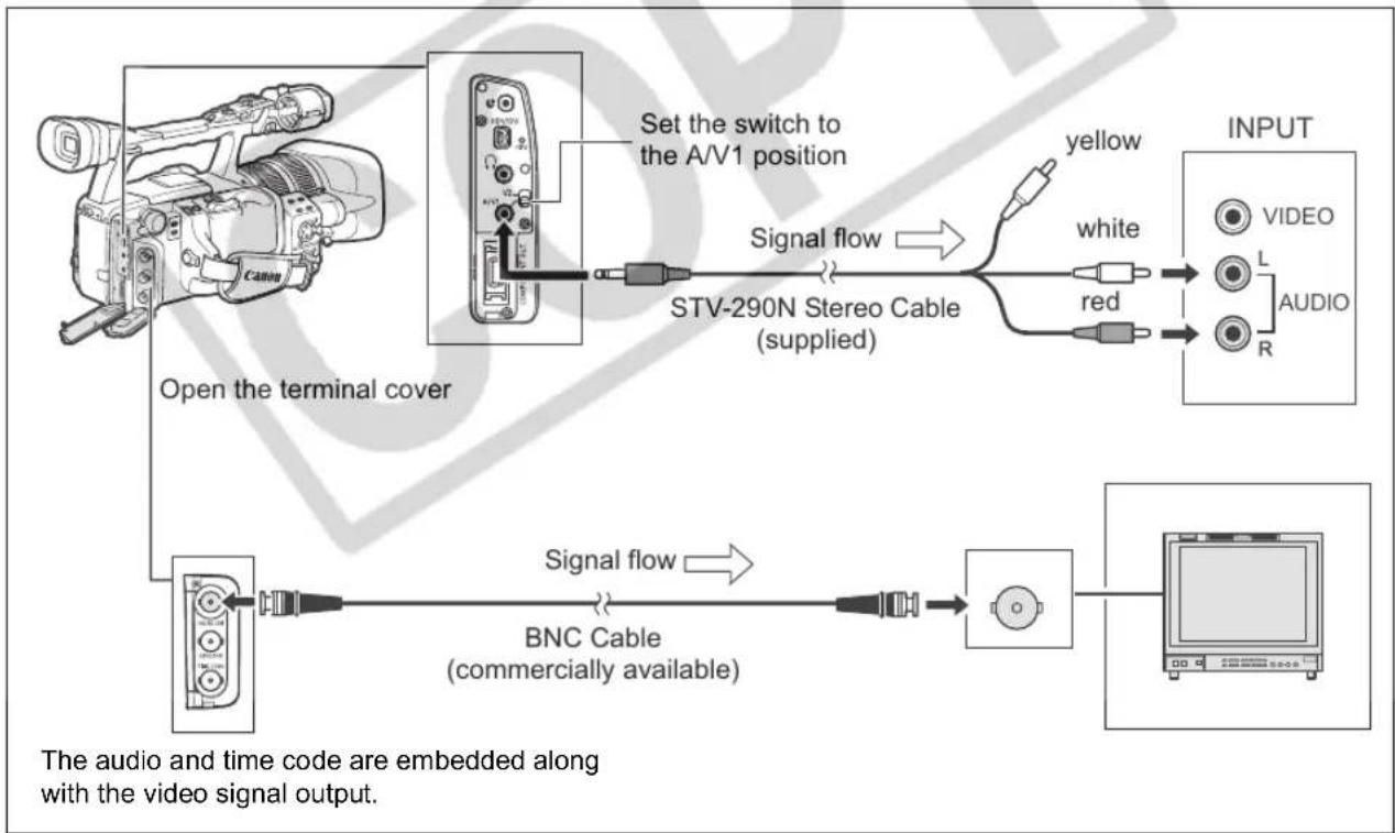
flowchart
graph TD
    A["Open the terminal cover"] --> B["Set the switch to the A/V1 position"]
    B --> C["STV-290N Stereo Cable (supplied)"]
    C --> D["Signal flow"]
    D --> E["OUTPUT"]
    E --> F["VIDEO"]
    E --> G["L"]
    E --> H["AUDIO"]
    E --> I["R"]
    J["BNC Cable (commercially available)"] --> K["Signal flow"]
    K --> L["OUTPUT"]
Activate the HD/SD SDI output and select the appropriate video output option (HD or SD).
- Set the PDAVEO .
VCR/PLAY
- Open the menu and select [SIGNAL SETUP]. Select [SDI OUTPUT] and set it to [ON].
- From the same [SIGNAL SETUP] submenu select [SDI SPEC.]. Select [AUTO] or [SD LOCKED] to match the video output you wish to use.
- Close the menu.
② Using the COMPONENT OUT Terminal
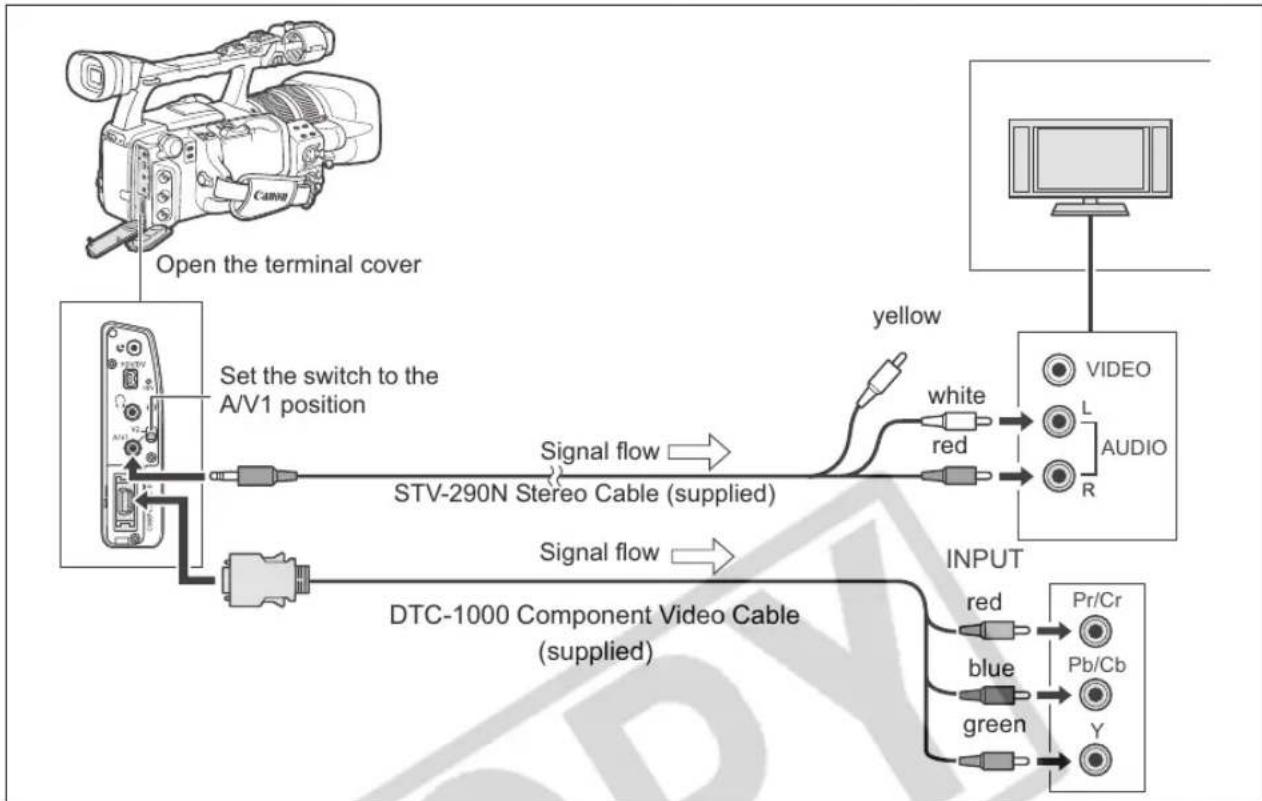
flowchart
graph TD
    A["Open the terminal cover"] --> B["Set the switch to the A/V1 position"]
    B --> C["STV-290N Stereo Cable (supplied)"]
    C --> D["yellow"]
    D --> E["VIDEO"]
    D --> F["L"]
    D --> G["R"]
    E --> H["AUDIO"]
    F --> H
    G --> H
    I["DTC-1000 Component Video Cable (supplied)"] --> J["INPUT"]
    J --> K["Pr/Cr"]
    J --> L["Pb/Cb"]
    J --> M["Y"]
    J --> N["green"]
    J --> O["blue"]
    J --> P["red"]
    C --> Q["Signal flow"]
    Q --> R["STV-290N Stereo Cable (supplied)"]
    R --> S["Signal flow"]
Select the appropriate component video signal depending on the TV or monitor you connect.
Open the menu and select [SIGNAL SETUP]. Select [COMP. OUT], select a setting option and close the menu.
③ Using the HDV/DV Terminal
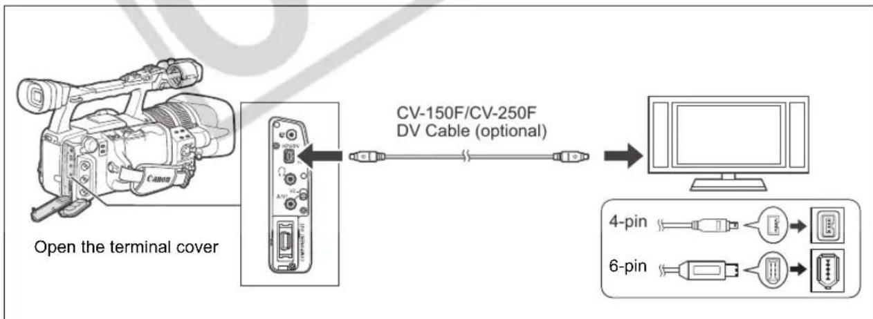
flowchart
graph LR
    A["Open the terminal cover"] --> B["CV-150F/CV-250F DV Cable (optional)"]
    B --> C["Computer"]
    D["4-pin"] --> E["Device 1"]
    F["6-pin"] --> G["Device 2"]
    E --> H["Output"]
    G --> I["Output"]
- When connecting the camcorder to a monitor TV that supports DV, you may need to carry out a procedure on the TV to recognize the camera. Refer to the instruction manual of the TV or monitor.
- If necessary, turn on the DV conversion and select whether to convert a tape recorded in HD to SD with the following procedure.
Open the menu and select [SIGNAL SETUP]. Select [HD DOWN-CONV], select a setting option and close the menu.
4 Using the VIDEO Terminal
If connecting to a TV, set the input selector to VIDEO. If connecting to a VCR, set the input selector to LINE. Refer also to the instruction manual of the TV or VCR.
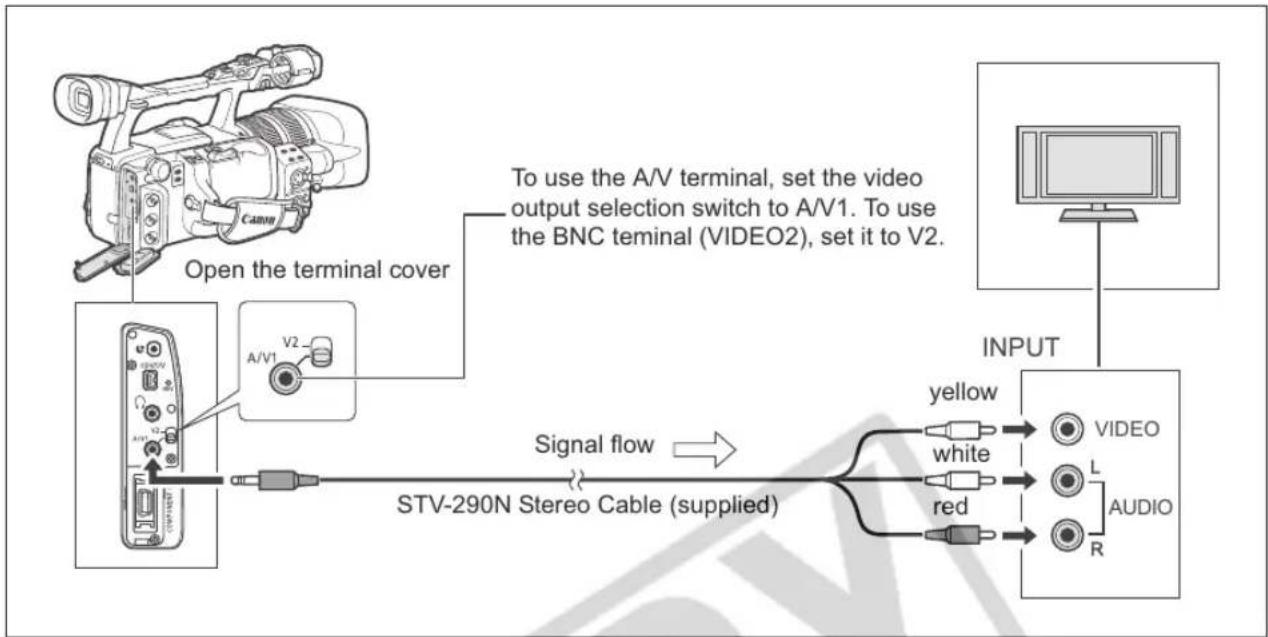
flowchart
graph TD
    A["Camera"] -->|Open the terminal cover| B["StV-290N Stereo Cable (supplied)"]
    B -->|Signal flow| C["STV-290N Stereo Cable (supplied)"]
    C --> D["video output selection switch to A/V1"]
    C --> E["BNC terminal (VIDEO2), set it to V2"]
    D --> F["VIDEO"]
    E --> G["L"]
    E --> H["R"]
    F --> I["OUTPUT"]
    G --> I
    H --> I
    style A fill:#f9f,stroke:#333
    style B fill:#ccf,stroke:#333
    style C fill:#cfc,stroke:#333
    style D fill:#fcc,stroke:#333
    style E fill:#cff,stroke:#333
    style F fill:#ffc,stroke:#333
    style G fill:#ffc,stroke:#333
    style H fill:#ffc,stroke:#333

We recommend powering the camcorder from a household power outlet.
Connection to a Normal TV or Monitor (Non-HDTV/HiVision)
① Using the COMPONENT OUT Terminal
Refer to the connection diagram in the previous section (98).
Select the appropriate component video signal depending on the TV or monitor you connect.
Open the menu and select [SIGNAL SETUP]. Select [COMP. OUT], select a setting option and close the menu.
② Using the VIDEO Terminal
Refer to the connection diagram in the previous section (99).
If connecting to a TV set the input selector to VIDEO. If connecting to a VCR, set the input selector to LINE.
Refer also to the instruction manual of the TV or VCR.
If connecting to a TV set with a 4:3 aspect ratio, change the [LETTERBOX] setting appropriately.
Open the menu and select [SIGNAL SETUP]. Select [LETTERBOX], set it to [ON] and close the menu.

We recommend powering the camcorder from a household power outlet.
| TAPE | CARD | EXT.CONT. | VCR/PLAY | A | Tv | Av | M |
Selecting the Audio
MENU
(25)
AUDIO SETUP
SEL AUDIO CH·CH 1/3 / CH 2/4
Open the menu and select [AUDIO SETUP]. Select [SEL AUDIO CH], select a setting option and close the menu.
Selecting the Audio Monitor
MENU
(25)
AUDIO SETUP
AUD.M.SET...CH 1/2
Open the menu and select [AUDIO SETUP]. Select [AUD.M.SET], select a setting option and close the menu.
If you selected [MIX/VAR.], adjust the mix balance with the MIX BALANCE buttons on the wireless controller.
| Audio Output Selected | Audio Recordings on 2 Channels | Audio Monitor [AUD.M.SET] | Audio Recordings on 4 Channels |
| CH 1/3 / CH 2/4 | Left Output: L or CH1Right Output: R or CH2 | CH 1/2 | Left Output: CH1Right Output: CH2 |
| CH 3/4 | Left Output: CH3Right Output: CH4 | ||
| MIX/FIXED | Left Output: CH1+CH3Right Output: CH2+CH4Mix balance fixed at 1:1 | ||
| MIX/VAR. | Left Output: CH1+CH3Right Output: CH2+CH4Mix balance can be adjusted | ||
| CH 1/3 / CH 1/3 | Left Output: L or CH1Right Output: L or CH1 | CH 1/2 | Left Output: CH1Right Output: CH1 |
| CH 3/4 | Left Output: CH3Right Output: CH3 | ||
| MIX/FIXED | Left Output: CH1+CH3Right Output: CH1+CH3Mix balance fixed at 1:1 | ||
| MIX/VAR. | Left Output: CH1+CH3Right Output: CH1+CH3Mix balance can be adjusted | ||
| CH 2/4 / CH 2/4 | Left Output: R or CH2Right Output: R or CH2 | CH 1/2 | Left Output: CH2Right Output: CH2 |
| CH 3/4 | Left Output: CH4Right Output: CH4 | ||
| MIX/FIXED | Left Output: CH2+CH4Right Output: CH2+CH4Mix balance fixed at 1:1 | ||
| MIX/VAR. Left Output: CH2+CH4Right Output: CH2+CH4Mix balance can be adjusted | |||
Returning to a Pre-marked Position
If you wish to return to a particular scene later, mark the point with the zero set memory, and the tape will stop at that point when you rewind/fast forward the tape.
This function is operated with the wireless controller.
E
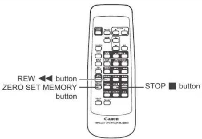
text_image
REW ◀ button ZERO SET MEMORY button STOP ■ button CanonTAPE
CARD
EXT. CONT.
VCR/PLAY
A
Tv
Av
M
[Non-Text]
[NO TEXT]
□
-
During playback, press the ZERO SET MEMORY button at the point you wish to return to later.
-
The tape counter is reset to 0:00:00 and the M mark appears.
• To cancel, press the ZERO SET MEMORY button again. -
After you finish playing back the tape, stop and rewind it.
-
If the tape counter shows a negative value, fast forward the tape instead.
- The tape stops automatically at "0:00:00" and the M mark disappears.
• The tape counter changes to time code.

The zero set memory may not function correctly if the time code has not been recorded consecutively.
The zero set memory function may not work correctly if you mix recordings in HDV and DV standards on the same tape.
With the index search you can locate any point you have marked beforehand with an index signal (71). This function is operated with the wireless controller.
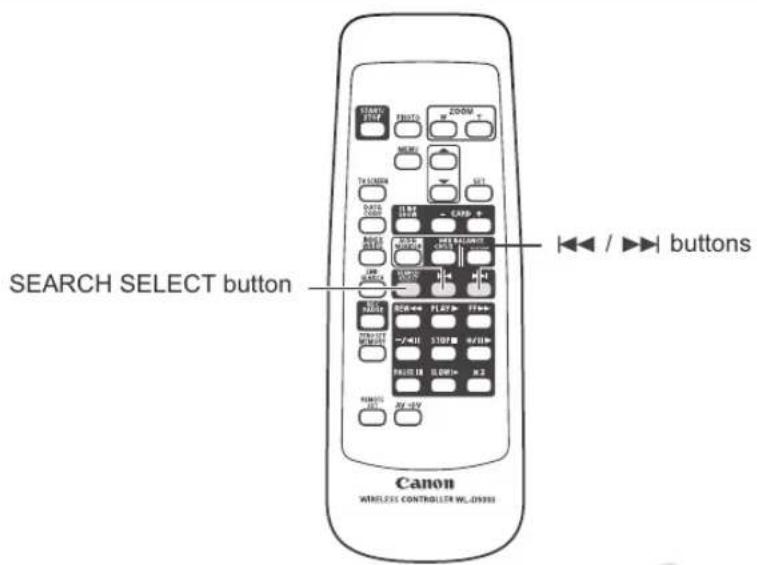
text_image
SEARCH SELECT button CANON WIRELESS CONTROLLER WLD0380| TAPE | CARD | EXT.CONT. | VCR/PLAY | A | Tv | Av | M |
- Press the SEARCH SELECT button to display "INDEX SEARCH".
→ xuva appears.
-
Press the ◀◀ or ▶▶ button to begin searching.
-
Press more than once to search for further index signals (up to 10 times).
- Press the STOP ■ button to stop searching.

○ Playback may start slightly before or after the index signal.
The index search function may not work correctly if you mix recordings in HDV and DV standards on the same tape.
You can locate the change of the date/time zone with the date search function.
This function is operated with the wireless controller.
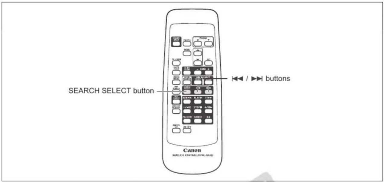
text_image
SEARCH SELECT button ◀◀ / ▶▶▶ buttons Canon WIRELESS CONTROLLER WL-05302
text_image
TAPE CARD EXT. CONT. VCR/ PLAY A Tv Av M ↑ ↓ □- Press the SEARCH SELECT button to display "DATE SEARCH".
→ appears.
-
Press the ◀◀ or ▶▶ button to begin searching.
-
Press more than once to search for further date changes (up to 10 times).
- Press the STOP ■ button to stop searching.

○ A recording of longer than a minute per date/time zone is required.
○ The date search may not function if the data code is not correctly displayed.
The date search function may not work correctly if you mix recordings in HDV and DV standards on the same tape.
The camcorder maintains a data code containing the recording date and time and other camera data such as shutter speed, gain and exposure (f-stop).
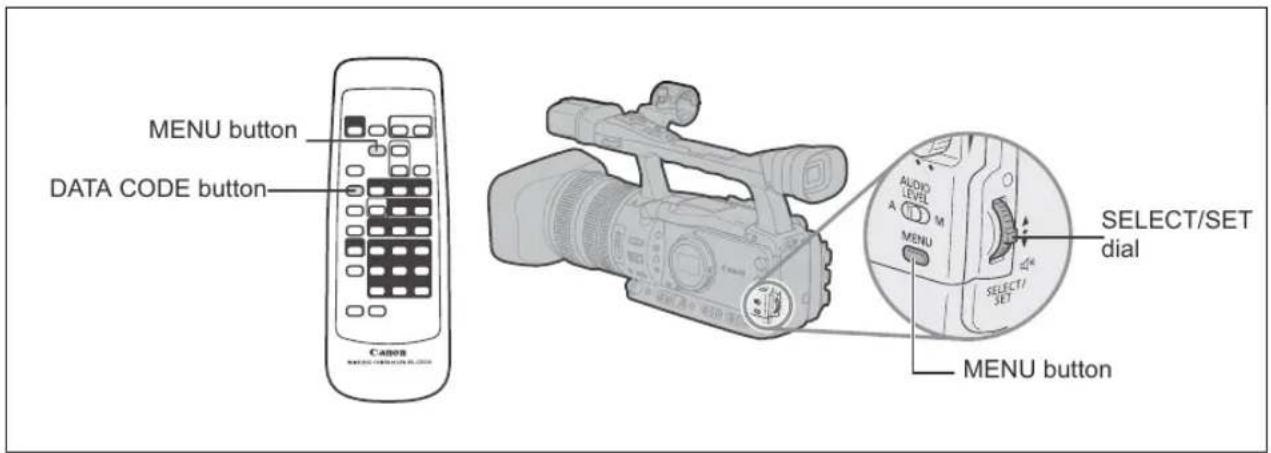
text_image
MENU button DATA CODE button Canon AUDIO/LEVEL A M MENU SELECT/SET dial SELECT/SET MENU button
text_image
TAPE CARD EXT. CONT. VCR/ PLAY A Tv Av M ↑ ↓ □Selecting the Data Code Display Combination

text_image
MENU (25) DISPLAY SETUP/ DATA CODE···DATE & TIMEOpen the menu and select [DISPLAY SETUP/∅]. Select [DATA CODE], select a setting option and close the menu.
Displaying the Data Code
Press the DATA CODE button on the wireless controller.

The data code will not appear the next time you turn on the camcorder.
Six-Second Auto Date
The date and time appear for 6 seconds when you begin playback, or to indicate that the date or time zone has changed.

text_image
MENU (25) DISPLAY SETUP/6SEC.DATE···OFFOpen the menu and select [DISPLAY SETUP/☐]. Select [6SEC.DATE], set it to [ON] and close the menu.
Two remote sensor modes and an off setting are available to prevent interference from other Canon wireless controllers being used nearby.
To change the remote sensor mode of the camcorder
Change the [WIRELESS REMOTE] setting of the custom function file (89).
To change the remote sensor mode of the wireless controller
Press the ZOOM T button and keep it pressed for over 2 seconds to change the wireless controller to mode 2. Press the ZOOM W button and keep it pressed for over 2 seconds to change the wireless controller to mode 1.
If you have set the camcorder to mode 1, press the ZOOM W button for mode 1.

The wireless controller returns to mode 1 when you replace the batteries. Change the mode if necessary.
○ Make sure that the camcorder and wireless controller are set to the same mode. Display the camcorder's mode by pressing any button on the wireless controller (except the REMOTE SET button) and set the wireless controller's mode to the same mode. Change the batteries if the wireless controller still does not work.
Recording an External Video Signal (Analog Line-In, HDV|DV In)
You can record on the tape an external video signal, either from the analog video input (SD standard) or from the HDV/DV input (SD or HD standard).
| TAPE | CARD |
| EXT.CONT. | VCR/PLAY | A | Tv |
| Av | M |
Analog Line-In
- Connect the camcorder to the analog video device.
For the connection diagram to an analog device refer to Section 4 of Connecting to a Monitor/TV (☐ 99). - Set the POWER dial to VCR/PLAY and load a blank cassette.
- Open the menu and select [AUDIO SETUP]. Select [DV AUDIO], select a setting option and close the menu.
- Connected device: Load the recorded cassette.
- Press the ● and || buttons (or the REC PAUSE button on the wireless controller).
- The camcorder enters the record pause mode. In this mode you can monitor the picture on the screen.
- If you press only the ● button, recording will start immediately.
- Connected device: Play back the tape.
- Press the Ⅲ button (or the PAUSE Ⅲ button on the wireless controller) when the scene you wish to record appears.
Recording starts. - Press the ■ button to stop recording.
- Connected device: Stop playback.
HDV/DV In
When recording from an external digital device you can select the time code to be used for the recording made with this camcorder. Select [COPY] to keep the original time code of the video source, or [REGEN.] to use instead this camcorder's internal time code.
-
Open the menu, select [SIGNAL SETUP] and then select the [TIME CODE] submenu.
-
Select [HDV/DV IN], select a setting option and close the menu.
-
Connect the camcorder to the external video device.
For the connection diagram to a digital device refer to Section 3 of Connecting to a Monitor/TV (☐ 98).
-
Set the POWER dial to VCR/PLAY and load a blank cassette.
-
Connected device: Load the recorded cassette or disc.
-
Press the ● and ▪ buttons (or the REC PAUSE button on the wireless controller).
-
The camcorder enters the record pause mode. In this mode you can monitor the picture on the screen.
-
If you press only the ● button, recording will start immediately.
-
Connected device: Start the playback.
-
Press the Ⅲ button (or the PAUSE Ⅲ button on the wireless controller) when the scene you wish to record appears.
Recording starts.
-
Press the ■ button to stop recording.
-
Connected device: Stop playback.
Copyright Signal
Certain software tapes are copyright protected. If you attempt to play back such tape, "COPYRIGHT PROTECTED PLAYBACK IS RESTRICTED" appears and you will not be able to view the contents of the tape. If you attempt to record from such tape via the DV terminal, "COPYRIGHT PROTECTED DUBBING RESTRICTED" appears and you will not be able to record the contents of the tape.
E

We recommend powering the camcorder from a household power outlet.
Converting Analog Signals into Digital Signals (Analog-Digital Converter)
Using the camcorder you can convert analog video input signals to a digital video signal (SD standard) and output it through the HDV/DV terminal.

text_image
TAPE CARD EXT. CONT. VCR/ PLAY A Tsv Av M MENU (25) SIGNAL SETUP AV→DV·······OFFOpen the menu and select [SIGNAL SETUP]. Select [AV⇒DV], set it to [ON] and close the menu.

○ Depending on the signal sent from the connected device, the conversion from analog to digital signals might not work properly (e.g., signals that include copyright protection signals or anomalous signals such as ghost signals).
For normal use, set [AV→DV] to [OFF]. If it is set to [ON], digital signals cannot be input via the camcorder's HDV/DV terminal.
○ Depending on the software and the specifications of your computer, you may not be able to transfer converted signals via the HDV/DV terminal.

- We recommend powering the camcorder from a household power outlet.
- You can also press the AV⇒DV button on the wireless controller. Repeatedly pressing the controller's button will toggle the AV⇒DV conversion on and off.
To connect the camcorder to a computer you need to ensure the following requirements: a computer equipped with an IEEE1394 (DV) terminal and video editing software with video capturing capability installed. Use the optional CV-150F (4 pin-4 pin) or CV-250F (4 pin-6 pin) DV cable. For the minimum system requirements for video editing, refer to the instruction manual of the video editing software.
Windows XP (SP2) users can use the CONSOLE software (sold separately) to download video and audio recordings (in HDV or DV standards) from the camcorder to the computer's hard disk. For details refer to the software's help modules.
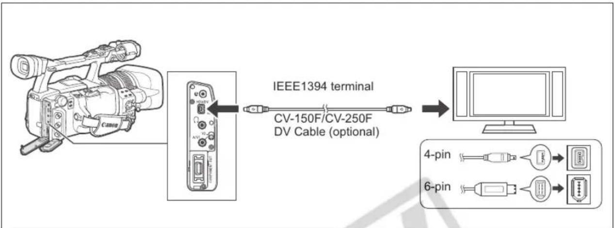
flowchart
graph LR
    A["Camera"] --> B["Device"]
    B --> C["IEEE1394 terminal"]
    C --> D["Computer"]
    D --> E["4-pin"]
    D --> F["6-pin"]
    style A fill:#f9f,stroke:#333
    style B fill:#ccf,stroke:#333
    style C fill:#cfc,stroke:#333
    style D fill:#fcc,stroke:#333
    style E fill:#ffc,stroke:#333
    style F fill:#cff,stroke:#333

Operation may not work correctly depending on the software and the specifications/settings of your computer.
○ If the computer freezes while you have connected the camcorder, disconnect and reconnect the DV cable. Should the problem persist, disconnect the cable, turn both the camcorder and the computer off and the on again and reconnect them.
○ Make sure that the computer video capturing system is compatible with the video signal standard you are using. If the computer is not compatible with the signal standard of the camcorder's video output, the camcorder may not be correctly detected or may not operate properly.

○ Refer also to the instruction manual of the computer and the editing software.
Adjust the [PLAYBACK STD] and [HD DOWN-CONV] settings in accordance with the video signal standards of the connected computer.
When outputting the camcorder's video signal to the computer:
- (HDV) video output: Set [PLAYBACK STD] to [HDV] and [HD DOWN-CONV] to [OFF].
- DV video output: Set [PLAYBACK STD] to [DV].
- DV video output of a recording originally made in HDV standard: Set [PLAYBACK STD] to [HDV] and [HD DOWN-CONV] to [ON].
When inputting a video signal from the computer to the camcorder:
- HDV video input: Set [PLAYBACK STD] to [HDV] and [HD DOWN-CONV] to [OFF].
- DV video input: Set [PLAYBACK STD] to [DV].
Changing the Still Image Quality
You can choose from Superfine, Fine and Normal.
| TAPE | CARD | EXT.CONT. | VCR/ *PLAY | A | Tv | Av | M |
* Only when playing back a tape.
| MENU(25) | RECORDING SETUP | IMG QUALITY··FINE |
Open the menu and select [RECORDING SETUP]. Select [IMG QUALITY], select a setting option and close the menu.
Changing the Still Image Size
The available image sizes will depend on the operation mode and the recording standard settings.
| Recording still images in CAMERA·CARD mode | Simultaneous recording of a still image in CAMERA mode | Capturing a still image in VCR/PLAY mode |
| LW 1920x1080 | [HD] or [SD16:9]: LW 1920x1080 | Recording made in [HD]: LW 1920x1080 |
| SW 848x480 | SW 848x480 | SW 848x480 |
| L 1440x1080 | [SD4:3]: L 1440x1080 | Recording made in [SD16:9]: SW 848x480 |
| 640x480 | 640x480 | Recording made in [SD4:3]: $ 640x480 |
| TAPE | CARD | EXT.CONT. | VCR/ *PLAY | A | Tv | Av | M |
* Only when playing back a tape.

text_image
MENU (25) RECORDING SETUP IMAGE SIZE...1440x1080 CAMERA CAMERA·CARD HD IMG SIZE...1440x1080 VCR/PLAYOpen the menu and select [RECORDING SETUP]. Select [IMAGE SIZE] ([HD IMG SIZE] in VCR/PLAY mode), select a setting option and close the menu.

- Still images are recorded on the memory card using JPEG compression.
○ Number of still images 🔒 that can be recorded on a memory card:
| Image Size | Image Quality | Number of Images | File Size per Image | ||
| 16MB | 128MB | 512MB | |||
| LW 1920 x 1080 | Super Fine | 9 | 90 | 350 | 1360 kB |
| Fine | 14 | 135 | 525 | 910 kB | |
| Normal | 28 | 265 | 1035 | 460 kB | |
| SW 848 x 480 | Super Fine | 50 | 455 | 1770 | 280 kB |
| Fine | 70 | 645 | 2510 | 190 kB | |
| Normal | 140 | 1295 | 5030 | 100 kB | |
| L 1440 x 1080 | Super Fine | 12 | 120 | 470 | 1020 kB |
| Fine | 19 | 180 | 700 | 690 kB | |
| Normal | 38 | 350 | 1370 | 350 kB | |
| $ 640 x 480 | Super Fine | 65 | 595 | 2320 | 215 kB |
| Fine | 95 | 865 | 3350 | 149 kB | |
| Normal | 170 | 1555 | 6035 | 82 kB | |
-These figures are approximate. They vary according to the recording condition and the subject. -The total number of still images that can be recorded will decrease if you store custom preset files on the card.
File Numbers
Still images are automatically assigned file numbers from 0101 to 9900, and stored in folders containing up to 100 images. Folders are numbered from 101 to 998.
| RESET | The file number will be reset each time a new memory card is inserted. If the memory card already contains image files, the consecutive file number will be assigned. |
| CONTINUOUS The camcorder memorizes the file number of the last image and assigns the consecutive file number to the next image, even when a new memory card is inserted. (If a higher file number already exists on the memory card, the consecutive number will be assigned.) There will be no duplication of file numbers. This is useful for organizing images on a computer. | |
| TAPE | CARD | EXT.CONT. | VCR/ *PLAY | A | Tv | Av | M |
* Only when playing back a tape.
| MENU(25) | RECORDING SETUP | FILE NOS.···CONTINUOUS |
To change the setting, open the menu and select [RECORDING SETUP]. Select [FILE NOS.], set it to [RESET] and close the menu.
Recording Still Images on a Memory Card
You can record still images directly on the memory card. You can also record still images on the memory card simultaneously while recording video on the tape and capture still images while playing back a tape.
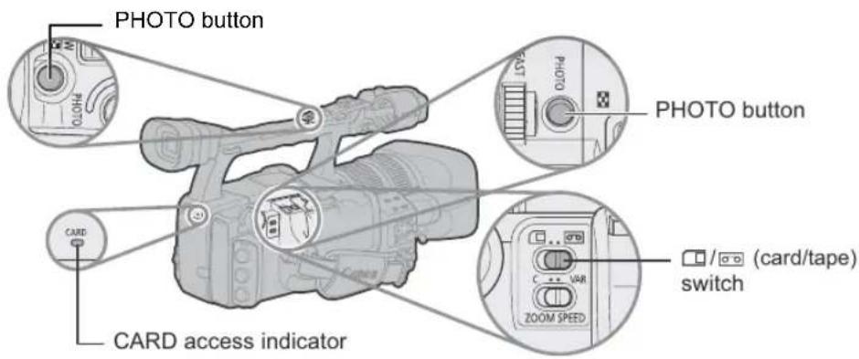
text_image
PHOTO button CARD CARD access indicator PHOTO button VAR ZOOM SPEED (/ / (card/tape) switch| TAPE | CARD |
| EXT.CONT. | VCR/PLAY | A | Tv | Av | M |
-
Turn the POWER dial to a recording program and move the ☐/☐ (card/tape) switch to ☐.
-
Press the PHOTO button halfway.
-
The ⬤ symbol turns green once the focus is adjusted. The picture may appear out of focus for a moment while the camcorder is focusing.
- While the PHOTO button is half-pressed you can also use the focusing ring to adjust the focus.
- Exposure is locked.
-
When you press the PHOTO button on the wireless controller, recording starts immediately.
-
Press the PHOTO button fully.
• The ● symbol disappears.
- The CARD access indicator flashes and the card access display appears.
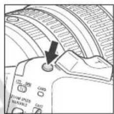
text_image
Diagram of a camera module with labeled buttons and an arrow pointing to the button on the screen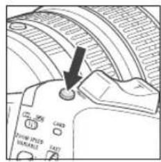
text_image
Diagram of a device control panel with labeled buttons and an arrow pointing to a button on the left side.
When you are using an SDHC memory card or SD Memory Card, make sure that the protect switch is set to allow recording. If you attempt to record a still image on a write-protected memory card the message "THE CARD IS SET FOR ERASURE PREVENTION" will be displayed.
Do not turn off the camcorder, change the position of the ☐/☐ (card/tape) switch or the POWER dial or remove the memory card while the CARD access indicator is flashing. Doing so could result in data damage.

When the Focus-Priority mode is set to [ON] in the custom function file (☐ 88):
When you press the PHOTO button fully before the ● symbol turns green, it may take up to 2 seconds (4 seconds in the Night recording program) until the focus is adjusted.
If the subject is not suitable for autofocus, the camcorder locks the focus. In that case, adjust the focus manually with the focusing ring.
When the Focus-Priority mode is set to [OFF] in the custom function file (88):
In step 2, turns green, and focus and exposure are locked.
○ About the Power Save function:
In CAMERA·CARD mode: In order to save power when the camcorder is powered with a battery pack, the camcorder will automatically enter the power save mode if you do not operate it for 5 minutes. With the [POWER SAVE] option in the custom function file (☐ 89) you can select if the power will be turned off (set it to [ON]) or not (set it to [OFF]).
If you set the power save option to [ON] and the camcorder automatically powered off, in order to resume recording press the STANDBY button or turn the POWER dial to OFF and then back to a recording mode.
Recording a Still Image on a Memory Card While Recording Movies on a Tape
With the customized functions (☐ 83) you can select to activate the simultaneous recording of a still image while recording movies on the tape. If you select [ON+CP DATA] you can also save the custom preset settings currently in use along embedded within the still image. This is very useful when you want to load the custom preset file later by selecting the still image captured from a specific scene.
| TAPE | CARD |
| EXT.CONT. | VCR/PLAY | A | Tv | Av | M |
-
Activate the simultaneous recording of still images with the custom function settings (☐ 88).
-
While you are recording the movie, press the PHOTO button.

OFF appears if you press the PHOTO button while [SIMULT.IMG.REC] is set to [OFF].
Capturing a Still Image from a Tape
With the customized functions (☐ 83) you can select to activate the capturing of a still image during playback pause.
| TAPE | CARD |
| EXT.CONT. | VCR/PLAY | A | Tv | Av | M |
- Activate the capturing of still images with the custom function settings (☐ 88).
- In playback pause, press the PHOTO button to record the frame as a still image on the memory card.
Screen Displays during Still Image Recording
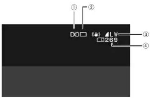
text_image
① ② LW 269 ③ ④① Metering Method Icon (117)
Indicates the metering mode currently selected for recording still images.
② Drive Mode Icon (115)
Indicates the drive mode currently selected for recording still images.
③ Image Quality and Size
Indicates the quality and size currently selected for recording still images.
④ Remaining Card Capacity for Still Images
flashing in red: No card
in green: 6 or more images
in yellow: 1 to 5 images
in red: No more images
- The indication may not decrease even though a recording has been made, or may decrease by 2 images at once.
- All indicators are displayed in green when a memory card is played back.
"►" Card Access Display
Indicates that the camcorder is writing on the memory card.
Selecting the Drive Mode
| Continuous Shooting Captures | a quick series of still images while you hold the PHOTO button |
| High-Speed Continuous | pressed down. For the number of frames per second, refer to the table below. |
| AEB(Auto Exposure Bracketing) | The camcorder records a still image in three different exposures (dark, normal, light in 1/2 EV steps). |
| Single Records a single still image when you press the PHOTO button. | |
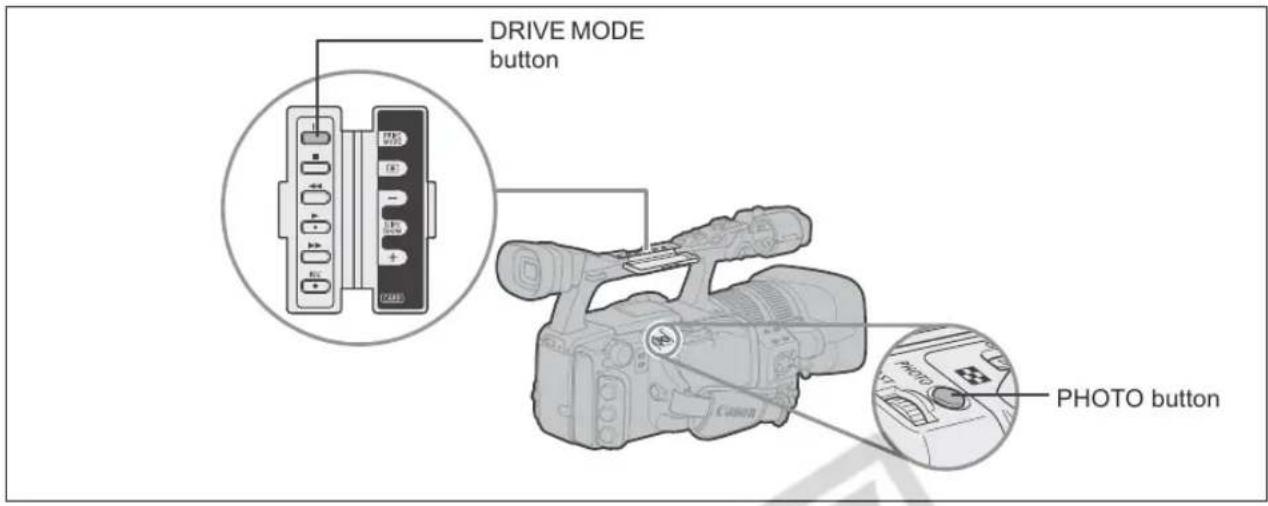
text_image
DRIVE MODE button PHOTO button| TAPE | CARD | EXT.CONT. | VCR/PLAY | A | Tv | Av | M |
Changing the Drive Mode
- Set the POWER dial to a recording program other than □ and move the □/□ (card/tape) switch to □.
- Press the DRIVE MODE button to switch between the drive modes.
The setting changes with each press of the button.
Continuous Shooting/High-Speed Continuous Shooting
Press and hold the PHOTO button.
A series of still images will be recorded as long as you hold the PHOTO button pressed down.

Maximum number of continuous shots at one time:
| Frames per Second | Maximum Number of Continuous Shots | |
| Normal speed | High speed | |
| 3 frames | 5 frames | 60 images |
- These figures are approximate and vary with the recording conditions and subjects.
- Sufficient space on the memory card is required. The continuous shooting will stop when the card is full.
Press the PHOTO button.
Three still images in different exposures are recorded to the memory card.

Make sure that there is sufficient space on the memory card.
Selecting the Metering Method
| EVALUATIVE Appropriate for standard shooting conditions, including backlit scenes. | |
| The camcorder divides images into several zones for light metering. It evaluates the position and brightness of the subject, background, direct light or backlight, and adjusts the exposure of the main subject accordingly. | |
| CENT.WEIGHT.AVERAGE | Averages the light metered from the entire screen, giving more weight to the subject in the center. |
| SPOT | Meters the area within the spot AE point frame. |
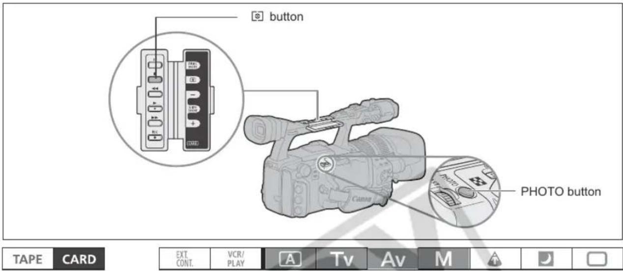
text_image
button PHOTO button TAPE CARD EXT. CONT. VCR/ PLAY A Tv Av M- Set the POWER dial to A, Tv, Av or M, and move the ☐/☐ (card/tape) switch to ☐.
-
Press the 🔒 button.
-
The setting changes with each press of the button.
- The symbol of the currently selected setting is displayed.
- If you selected (SPOT), the AE point frame appears in the center of the screen.
You can use E-TTL II compatible Canon Speedlite flashes designed for use with Canon SLR cameras, including the 420EX/430EX/550EX/580EX models, to record natural still images under low light conditions. Refer also to the instruction manual of the Speedlite flash.
Connecting a Speedlite Flash

When connecting a Canon Speedlite flash you cannot use the Off-Camera Shoe Cord designed for Canon EOS SLR cameras.
○ Always turn off the camcorder when connecting or detaching the flash.
-
Insert the mounting foot of the flash straight, fully into the hot shoe.
-
Tighten the locking ring.
As you turn the locking ring, the locking pin will come out and lock the flash in position.
To detach the flash:
Turn the locking ring all the way to the opposite direction. Verify that the locking pin was released and only then detach the flash from the advanced accessory shoe.
Using the Flash

text_image
EXT. CONT. VCR/ PLAY A Tv Av M A J-
Set the POWER dial to a recording mode other than M and turn on the flash.
-
While the Speedlite flash is charging, the f indicator will flash in white. Once charged, the f indicator will stay on in green.
-
If the 12 indicator keeps flashing in white for a long time, replace the flash's batteries.
-
Press the PHOTO button to record a still image.

- Wait until the flash is charged before recording the still image. You can record a still image while the flash is charging, but the flash will not go off.
○ Turn off the Speedlite flash when you are not using it.
○ The flash will not go off during exposure lock and in the M Manual mode.
○ While using the flash, the shutter speeds that can be set in Tv mode are 1/4 - 1/500.
The camcorder does not support the Bounce Flash function or the Wireless Multiple Flash System function of the Speedlite 420EX/430EX/550EX/580EX flashes.
The camcorder does not support the ST-E2 Wireless Speedlite Flash Transmitter or the Wireless Master/Slave Control function of the Speedlite 420EX/430EX/550EX/580EX flashes.
When recording under very dark conditions, as you keep the PHOTO button pressed halfway the AF assist lamp of the Speedlite flash may light on (when recording using the autofocus and with [FOCUS PRIORITY] set to [ON]).
The Speedlite flash will not go off when the drive mode is set to Auto Exposure Bracketing.
Reviewing a Still Image Right after Recording
You can select to display a still image for 2, 4, 6, 8 or 10 seconds after it has been recorded.

text_image
TAPE CARD EXT. CONT. VCR/ PLAY A Tv Av M
text_image
MENU (25) CAMERA SETUP REVIEW ...... 2SECOpen the menu and select [CAMERA SETUP]. Select [REVIEW], select a setting option and close the menu.

○ A still image is displayed as long as you hold the PHOTO button after recording.
The still image operations menu appears when you press the SELECT/SET dial while you are reviewing a still image, or when you press the SELECT/SET dial right after recording. In this menu, you can protect (☐ 123) or erase (☐ 122) the image.
☐ [REVIEW] cannot be selected when ☐ (continuous shooting), ☐ (high-speed continuous shooting) or ☐ (auto exposure bracketing) is selected.

Playing Back Still Images from a Memory Card
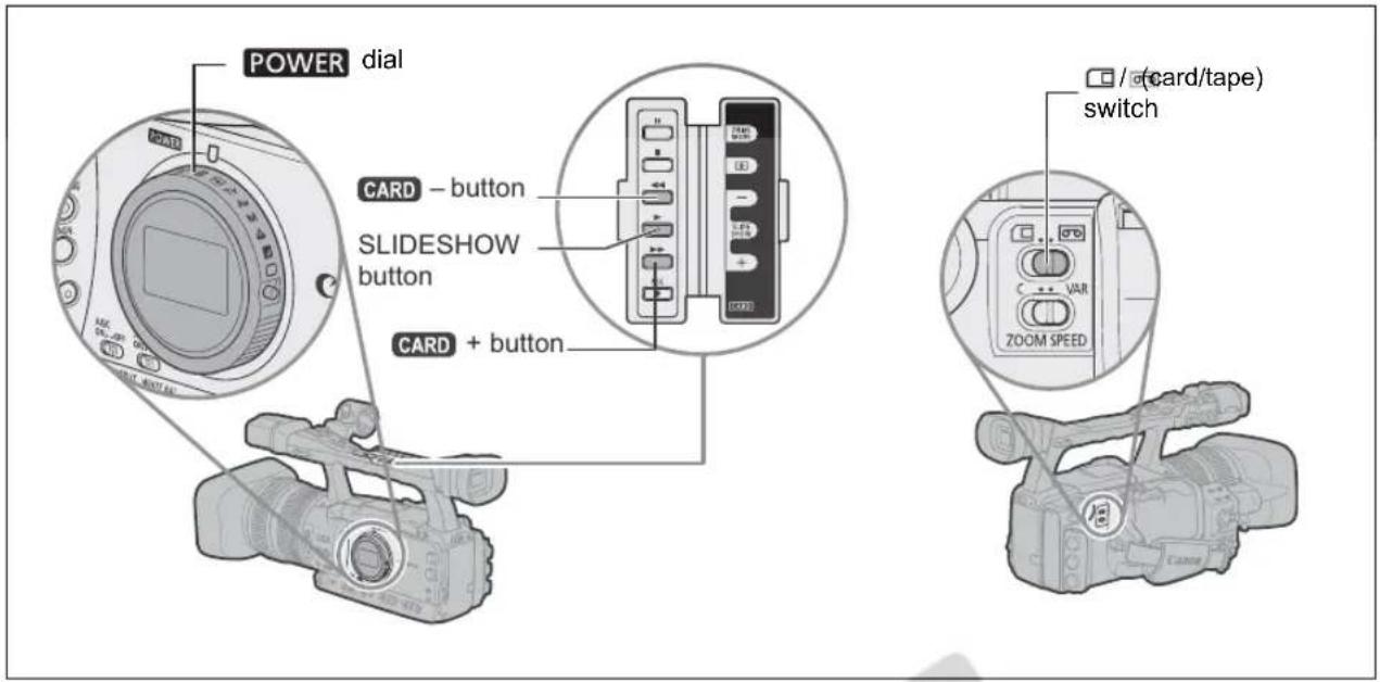
text_image
POWER dial CARD - button SLIDESHOW button CARD + button / (card/tape) switch| TAPE | CARD | EXT.CONT. | VCR/PLAY | A | Tv | Av | M |
- Turn the POWER dial to VCR/PLAY and move the / (card/tape) switch to □.
- Press the CARD + / - button to move between images.

Images not recorded with this camcorder, uploaded from a computer, edited on a computer and images whose file names have been changed may not be played back correctly.
Do not turn off the camcorder, change the position of the ☐/☐ (card/tape) switch or the POWER dial, open the memory card cover or remove the memory card while the CARD access indicator is flashing. Doing so could result in data damage.
Slideshow
Press the SLIDESHOW button.
• Images are played back one after another.
- Press the button again to stop the slideshow.
Index Screen
- Move the zoom lever toward W.
Up to 6 images appear.
-
Turn the SELECT/SET dial to select an image.
-
Move the "to the image you wish to view.
-
You can switch between the index pages by pressing the CARD button.
-
Move the zoom lever toward T or press the SELECT/SET dial.
The index screen is cancelled and the selected image is displayed.
Image Jump Function
You can locate images without displaying them one by one. The number in the upper right of the screen indicates the image number of the current image out of the total number of images.
Press and hold the CARD + / - button.
When you release the button, the image of the displayed image number appears.
Displaying the Recording Data
You can select whether to display all the recording data stored when the still image was recorded (histogram, camera information, etc.).
Repeatedly press the DISP. button to display the recording data.
You can erase images one at a time or all at once.

○ Be careful when erasing images. Erased images cannot be recovered.
- Erasing a still image that had a custom preset file embedded (recorded with the [ON+CP DATA] setting) will erase the image and the embedded custom preset file.

Protected images (☐ 123) cannot be erased.
Erasing a Single Image
| TAPE | CARD | EXT.CONT. | VCR/PLAY | A | Tv | Av | M |
- Select the image you wish to erase.
- Press the SELECT/SET dial to open the still image operations menu.
In CAMERA·CARD mode, the menu appears when you press the SELECT/SET dial while you are reviewing a still image, or if you press the SELECT/SET dial immediately after recording an image.
- Select [IMAGE ERASE].
- Select [ERASE].
The image is erased and the previous image appears.
- Select [←CLOSE] to close the menu.
Erasing All Images
| TAPE | CARD | EXT.CONT. | VCR/PLAY | A | Tv | Av | M |

text_image
MENU (□ 25) CARD OPERATIONS ▶ ERASE ALL IMAGES- Open the menu and select [CARD OPERATIONS].
- Select [ERASE ALL IMAGES].
- Select [YES] and close the menu.
All still images except the protected ones are erased.
You can protect important images from accidental erasure when displaying a single image or the index screen.

If a memory card is initialized, all still images, even protected ones, will be erased permanently.
| TAPE | CARD | EXT.CONT. | VCR/PLAY | A | Tv | Av | M |
- Select the image you wish to protect.
- Press the SELECT/SET dial to open the still image operations menu.
In CAMERA·CARD mode, the menu appears when you press the SELECT/SET dial while you are reviewing a still image, or if you press the SELECT/SET dial immediately after recording an image.
- Select [o=PROTECT].
- Select [ON].
"O" appears and now the image cannot be erased. To remove the protection select [OFF] instead.
- Select [←CLOSE] to close the menu.
Protecting during Index Screen Display
| TAPE | CARD | EXT.CONT. | VCR/PLAY | A | Tv | Av | M |

text_image
MENU CARD OPERATIONS → O=PROTECT-
Move the zoom lever toward W.
-
Up to 6 images appear.
-
Select the image you wish to protect.
-
Open the menu and select [CARD OPERATIONS]. Select [→ o=PROTECT] and press the SELECT/SET dial.
• On appears on the image.
- Select additional images with the SELECT/SET dial and protect them in the same way.
- Close the menu to return to the index screen.

Initialize new memory cards, or when you get the message "CARD ERROR". You can also initialize a memory card to erase all data recorded on it. The regular initialization option [INITIALIZE] will clear the file allocation table but will not physically erase the stored data. If you need to completely erase all the data, select instead the complete initialization option [COMPL.INIT.].

○ Initializing a memory card erases all data, including protected images and custom preset files.
○ Images and custom preset files erased through the card initialization cannot be recovered.
We recommend using the [COMPL.INIT.] option when you feel that the time it takes to record an image on or read an image from the memory card has become too long.
○ Depending on the memory card, the complete initialization may take up to a few minutes.
○ If you use a memory card other than the supplied one, initialize it with the camcorder.

text_image
TAPE CARD EXT. CONT. VCR/ PLAY A Tv Av M MENU CARD OPERATIONS INITIALIZE (25)- Open the menu and select [CARD OPERATIONS].
- Select [INITIALIZE] and select the regular or the complete initialization.
- [INITIALIZE]: Select [YES].
[COMPL.INIT.]: Select [YES] and, in the confirmation screen, select [YES] again.
• The card initialization starts.
- The complete initialization can be canceled halfway through by pressing the SELECT/SET dial. All the image files will be erased and the memory card can be used without any problem.
You can select still images for printing and set the number of copies. These print order settings are compatible with the Digital Print Order Format (DPOF) standards and can be used for printing on DPOF compatible printers. A maximum of 998 still images can be selected.
Selecting Still Images for Printing (Print Order)



- Select the still image you wish to print.
- Press the SELECT/SET dial to open the still image operations menu.
- Select [☐ PRINT ORDER].
-
Select the number of copies.
-
appears on the image.
-
To cancel the print order, set the number of copies to 0.
-
Select [←CLOSE] to close the menu.
Selecting in Index Screen Display

text_image
MENU CARD OPERATIONS → PRINT ORDER-
Move the zoom lever toward W.
-
Up to 6 images appear.
-
Select the image you wish to print.
-
Open the menu and select [CARD OPERATIONS]. Select [→ PRINT ORDER].
- Press the SELECT/SET dial and set the number of copies with the SELECT/SET dial.
• appears on the image.
• To cancel the print order, set the number of copies to 0.
- Close the menu to return to the index screen.
Erasing All Print Orders

text_image
MENU (25) CARD OPERATIONS PRINT ORD.ALL ERASE- Open the menu and select [CARD OPERATIONS].
- Select [PRINT ORD.ALL ERASE] and select [YES].
All disappear.
- Close the menu.

Settings Retained at Power Off or STANDBY Mode
The following list shows the settings that are retained when you turn the power off or press the STANDBY button. If the built-in lithium button battery discharges completely, all settings will be erased.
| CAMERA / (CAMERA·CARD) M | o | d | e | Changing between HD and SD* |
| Shutter speed setting in Tv mode | ||||
| Aperture setting in Av mode | ||||
| Aperture, shutter speed setting in Manual mode | ||||
| Custom white balance | ||||
| Exposure lock | Returns to off | |||
| Aperture, shutter speed setting during exposure lock | Reset | |||
| CAMERA MENU settings | ||||
| CAMERA·CARD MENU settings | ||||
| TV SCREEN on/off | ||||
| On-screen display settings | ||||
| Zero set memory* | ||||
* CAMERA mode only.
The following list shows the settings that are retained when you change the programmed AE mode or frame rate.
| CAMERA / CAMERA·CARD Modes | When you change to a recording program other than □ Easy Recording | When you change to □ Easy Recording | When you change the frame rate* |
| Shutter speed setting in Tv mode | ● | ||
| Aperture setting in Av mode | ● | ||
| Aperture, shutter speed setting in Manual mode | ● | ||
| Custom white balance | ● | ||
| Exposure lock | Returns to off | ||
| Aperture, shutter speed setting during exposure lock | Reset | ||
| CAMERA MENU setting | ● | ||
| CAMERA·CARD MENU settings | ● | ||
| TV SCREEN on/off | ● | ||
| On-screen display settings | ● | ||
* CAMERA mode only.
Default settings are shown in boldface.
CAMERA CAMERA MENU
*Only in Standard Definition (SD).
** XHG1 only.
| Submenu Menu Item | Setting Options | ☐ | ||
| SIGNAL SETUP TIME | CODE FRAME | SETTING | DROP, NON-DROP 42 | |
| COUNT-UP | REC-RUN, REC-RUN PS., FREE-RUN ^1 | |||
| START VALUE | SET, RESET | |||
| GENLCK ADJST** | -1023 – 1023 | 44 | ||
| SIGNAL STD | HD, SD16:9, SD4:3 | 31 | ||
| FRAME RATE | 60i, 30F, 24F | 40 | ||
| COMP. OUT | 480i, 1080i/480i | 98 | ||
| SDI OUTPUT** | ON, OFF | 97 | ||
| SDI SPEC.** | AUTO, SD LOCKED | 97 | ||
| CAMERA SETUP | 24F MODE SEL* | 2:3, 2:3:3:2 | 41 | |
| AE SHIFT | -2.0, -1.5, -1.25, -1.0, -0.75, -0.5, -0.25, ±0,+0.25, +0.5, +0.75, +1.0, +1.25, +1.5, +2.0 | 59 | ||
| GAIN SETTING | GAIN L | -3dB, ±0dB, 3dB, 6dB, 12dB, 18dB,36dB | 60 | |
| GAIN M | -3dB, ±0dB, 3dB, 6dB, 12dB, 18dB,36dB | |||
| GAIN H | -3dB, ±0dB, 3dB, 6dB, 12dB, 18dB,36dB | |||
| AF MODE | INSTANT AF, NORMAL AF | 35 | ||
| IMG STAB | ON (☑), OFF | 51 | ||
| SKIN DETAIL | EFFECT LEVEL | OFF, LOW ⚙, MIDDLE 📋,HIGH 🌐 | 67 | |
| HUE | ||||
| CHROMA | ||||
| AREA | ||||
| Y LEVEL | ||||
| SKY DETAIL | SOFT ⚠*, OFF | 68 | ||
| COLOR CORR. | CORRECT | OFF, A 🔒, B 🔒, A&B 🔒 | 65 | |
| A AREA SEL. | COLOR PHASE, CHROMA, AREA,Y LEVEL | |||
| A AREA REV. | R GAIN, B GAIN | |||
| B AREA SEL. | COLOR PHASE, CHROMA, AREA,Y LEVEL | |||
| B AREA REV. | R GAIN, B GAIN | |||
| F SPEED PSET | LOW, MIDDLE, HIGH | 38 | ||
| CLEAR SCAN | 69 | |||
| RECORDING SETUP | DV REC MODE* SP, LP 75 | |||
| UB REC INT. USR-BIT, EXT. USR-BIT 46 | ||||
| UB SELECT 00 00 00 00, TIME, DATE 46 | ||||
| IMG QUALITY SUPERFINE, FINE, NORMAL 110 | ||||
| IMAGE SIZE | HD or (SD16:9) LW 1920x1080, SW 848x480 (SD4:3) L 1440x1080, S 640x480 | 110 | ||
| FILE NOS. | RESET, CONTINUOUS | 111 | ||
| AUDIO SETUP | DV AUDIO* | 16bit, 12bit | 47 | |
| AUD.M.SET | NORMAL, LINE OUT | 49 | ||
| MIC MODE | NORMAL, VOICE ⚪, WS ≈/∥ | 47 | ||
| MIC SENS. | NORMAL, HIGH | 49 | ||
| XLR INPUT | ON→ XLR, OFF | 48 | ||
| XLR GAIN UP | OFF, 12dB | 48 | ||
| DISPLAY SETUP/∅ | CVF SETUP | BRIGHTNESS | 18 | |
| CONTRAST | ||||
| COLOR | ||||
| SHARPNESS | ||||
| BACKLIGHT | BRIGHT, NORMAL | |||
| LCD SETUP | BRIGHTNESS | 19 | ||
| CONTRAST | ||||
| COLOR | ||||
| SHARPNESS | ||||
| BACKLIGHT | BRIGHT, NORMAL | |||
| CVF+LCD BW | ON, OFF | 20 | ||
| CVF+LCD ON | ON, OFF | 20 | ||
| LANGUAGE ☎ | DEUTSCH, ENGLISH, ESPAÑOL, FRANÇAIS, ITALIANO, POLSKI, РУССКИЙ, 简体中文, 日本語 | 75 | ||
| MARKERS | OFF, LEVEL MARK., CENT. MARK., GRID | 30 | ||
| ASPECT GUIDE | OFF, 4:3, 13:9, 14:9, 1.66:1, 1.75:1, 1.85:1, 2.35:1 | 30 | ||
| SAFETY ZONE | OFF, 80%, 90% | 30 | ||
| ZEBRA | ON, OFF | 64 | ||
| ZEBRA LEVEL | 70, 75, 80, 85, 90, 95, 100 | 64 | ||
| TV SCREEN | ON, OFF | 90 | ||
| AUDIO LEVEL | ON, OFF | 49 | ||
| GUIDE INFO | OFF, CUSTOM KEYS, D/T DISPLAY | 29 | ||
| UB DISPLAY | ON, OFF | 46 | ||
| SYSTEM SETUP/∅ | CUSTOM KEY 1 | TIME CODE, INDEX WRITE, ZEBRA, VCR STOP, TV SCREEN, TC HOLD, AUDIO LEVEL, CVF+LCD BW, MAGN.B.LOCK, SHTR D.LOCK, (NONE) | 71 | |
| CUSTOM KEY 2 | TIME CODE, INDEX WRITE, ZEBRA, VCR STOP, TV SCREEN, TC HOLD, AUDIO LEVEL, CVF+LCD BW, MAGN.B.LOCK, SHTR D.LOCK, CP BKWD KEY, (NONE) | |||
| D/TIME SET √ | T.ZONE/DST | 26 | ||
| DATE/TIME | ||||
| DATE FORMAT Y.M.D. 2006.1.1 AM12:00 M.D.Y. JAN.1.2006 12:00AM D.M.Y. 1.JAN.2006 12:00AM | 75 | |||
| DV CONTROL | ON DV, OFF | 74 | ||
| MAGN.B.LOCK | DISABLED, ACTIVE | - | ||
| SHTR D.LOCK | DISABLED, ACTIVE | - | ||
| RESET ALL | NO, YES | - | ||
| CUSTOMIZE | ||||
| CUSTOM PRESET | EDIT SELECT CP | PRESET_A, | 2 PRESET_B,3 PRESET_C,4 PRESET_D,5 PRESET_E,6 PRESET_F,7 VIDEO.C,8 CINE.V,9 CINE.F | 76 |
| TUNE | ||||
| RENAME | ||||
| PROTECT | ||||
| RESET | ||||
| Setting Items: | ||||
| GAMMA | NORMAL, CINE1, CINE2 | |||
| KNEE | AUTO, LOW, MIDDLE, HIGH | |||
| BLACK | STRETCH, MIDDLE, PRESS | |||
| MASTER PED. | -9 ~ 9 | |||
| SETUP LEVEL | -9 ~ 9 | |||
| SHARPNESS | -9 ~ 9 | |||
| H DTL FREQ | LOW, MIDDLE, HIGH | |||
| DTL HV BALANCE | -9 ~ 9 | |||
| CORING | -9 ~ 9 | |||
| NR1 | OFF, LOW, MIDDLE, HIGH | |||
| NR2 | OFF, LOW, MIDDLE, HIGH | |||
| COLOR MAT. | NORMAL, CINE1, CINE2 | |||
| COLOR GAIN | -50 ~ 50 | |||
| COLOR PHASE | -9 ~ 9 | |||
| R GAIN | -50 ~ 50 | |||
| G GAIN | -50 ~ 50 | |||
| B GAIN | -50 ~ 50 | |||
| RG MATRIX | -50 ~ 50 | |||
| RB MATRIX | -50 ~ 50 | |||
| GR MATRIX | -50 ~ 50 | |||
| GB MATRIX | -50 ~ 50 | |||
| BR MATRIX | -50 ~ 50 | |||
| BG MATRIX | -50 ~ 50 | |||
| CAMERA → CARD | SELECT CP | 81 | ||
| SAVE POSITION | ||||
| EXECUTE | ||||
| CARD → CAMERA | IMPORT | 82 | ||
| SELECT POSITION | ||||
| EXECUTE | ||||
| Submenu | Menu Item | Setting Options | ☐ | ||
| CUSTOMIZE | |||||
| CUSTOM DISPLAY | TUNE | 90 | |||
| SAVE TO CARD | 91 | ||||
| READ FROM CARD | 91 | ||||
| RESET | 91 | ||||
| Setting Items: REC P | PROGRAMS 00 (OFF) - 01 (ON) | 91 | |||
| CAMERA DATA1 | 00 - 07 [03] | ||||
| CAMERA DATA2 | 00 - 07 | ||||
| ZOOM | 00 - 02 [01] | ||||
| FOCUS | 00 - 02 [01] | ||||
| ND | 00 (OFF) - 01 (ON) | ||||
| IMAGE EFFECTS | 00 - 07 | ||||
| F.ASSIST FUNC. | 00 - 03 | ||||
| CUSTOMIZE | 00 - 03 | ||||
| RECORDING STD | 00 (OFF) - 01 (ON) | ||||
| DV REC MODE | 00 (OFF) - 01 (ON) | ||||
| FRAME RATE | 00 (OFF) - 01 (ON) | ||||
| TAPE | 00 - 07 [03] | ||||
| TAPE REMAINDER | 00 - 02 | ||||
| TAPE/CARD | 00 - 03 | ||||
| LIGHT METERING | 00 - 03 | ||||
| CARD | 00 - 07 [03] | ||||
| CARD REMAINDER | 00 - 02 | ||||
| AUDIO | 00 - 07 | ||||
| CONDENSATION | 00 (OFF) - 01 (ON) | ||||
| BATTERY | 00 - 02 | ||||
| WIRELESS REMOTE | 00 - 02 | ||||
| Submenu Menu Item | Setting Options | |||
| SIGNAL SETUP TIME | CODE FRAME | SETTING | DROP, NON-DROP 42 | |
| COUNT-UP REC-RUN, REC-RUN PS., FREE-RUN ^1 | 42 | |||
| START VALUE SET, RESET 42 | ||||
| HDV/DV IN REGEN., COPY 106 | ||||
| PLAYBACK STD | AUTO, HDV, DV | 95 | ||
| COMP. OUT | 480i, 1080i/480i | 98 | ||
| SDI OUTPUT** | ON, OFF | 97 | ||
| SDI SPEC.** | AUTO, SD LOCKED | 97 | ||
| AV → DV | ON, OFF | 108 | ||
| HD DOWN-CONV | ON, OFF | 98 | ||
| LETTERBOX | ON, OFF | 97 | ||
| RECORDING SETUP | DV REC MOD* | SP, LP | 75 | |
| UB SELECT | 00 00 00 00, TIME, DATE | 46 | ||
| IMG QUALITY | SUPER FINE, FINE, NORMAL | 110 | ||
| HD IMG SIZE | LW 1920x1080, SW 848x480 | 110 | ||
| FILE NOS. | RESET, CONTINUOUS | 111 | ||
| AUDIO SETUP | SEL AUDIO CH | CH 1/3/CH 2/4, CH 1/3/CH 1/3, CH 2/4/CH 2/4 | 100 | |
| AUD.M.SET | CH 1/2, CH 3/4, MIX/FIXED, MIX/VAR. | 100 | ||
| MIX BALANCE | 1/2 3/4 | 100 | ||
| DV AUDIO | 16bit, 12bit | 47 | ||
1 Cannot be selected in Standard Definition (SD) if the frame rate is set to 24F.
HD DOWN-CONV.: Selects whether to down-convert the video signal output from the HDV/DV terminal while playing back a tape recorded in HDV standard.
| Standard of the tape being played back | [HD DOWN-CONV] Setting | [PLAYBACK STD] Setting | ||
| [AUTO] | [HDV] | [DV] | ||
| HDV | [ON] | DV | DV | No output |
| [OFF] | HDV | HDV | No output | |
| DV | [ON] | DV | No output | DV |
| [OFF] | DV | No output | DV | |
The down-converted output video signal will always be 60 fps interlaced, regardless of the frame rate of the original recording.
Even if the audio was originally recorded using all 4 channels (with another camcorder), only channels 1 and 2 will be output.
VCR/PLAY VCR/PLAY MENU (cont.)
| Submenu Menu Item | Setting Options | ☐ | ||
| DISPLAY SETUP/☑ | SETUP BRIGHTNESS | S 18 | ||
| CONTRAST | ||||
| COLOR | ||||
| SHARPNESS | ||||
| BACKLIGHT BRIGHT, NORMAL | ||||
| LCD SETUP | BRIGHTNESS | 19 | ||
| CONTRAST | ||||
| COLOR | ||||
| SHARPNESS | ||||
| BACKLIGHT | BRIGHT, NORMAL | |||
| CVF+LCD BW | ON, OFF | 20 | ||
| CVF+LCD ON | ON, OFF | 20 | ||
| TV SCREEN | ON, OFF | 90 | ||
| AUDIO LEVEL | ON, OFF | 49 | ||
| LANGUAGE ☑ | DEUTSCH, ENGLISH, ESPAÑOL, FRANÇAIS, ITALIANO, POLSKI, РУССКИЙ, 筒体中文, 日本語 | 75 | ||
| CUSTOM KEY | ON, OFF | 70 | ||
| DATA CODE | DATE, TIME, DATE & TIME, CAMERA DATA, CAM. & D/T | 104 | ||
| 6 SEC.DATE | ON, OFF | 104 | ||
| UB DISPLAY | ON, OFF | 46 | ||
| SYSTEM SETUP/☑ | CUSTOM KEY 1 | TIME CODE, TV SCREEN, DATA CODE, AUDIO LEVEL, TC HOLD, CVF+LCD BW, (NONE) | 71 | |
| CUSTOM KEY 2 | TIME CODE, TV SCREEN, DATA CODE, AUDIO LEVEL, TC HOLD, CVF+LCD BW, (NONE) | |||
| D/TIME SET ☑ | T.ZONE/DST | 26 | ||
| DATE/TIME | ||||
| DATE FORMAT Y.M.D. 2006.1.1 AM12:00M.D.Y. JAN.1.2006 12:00AMD.M.Y. 1.JAN.2006 12:00AM | 75 | |||
| RESET ALL | NO, YES | - | ||
E
VCR/PLAY VCR/PLAY MENU (cont.)
| Submenu Menu Item | Setting Options | ||
| CUSTOMIZE | |||
| CUSTOM FUNCTION | C.Fn1, C.Fn2, C.Fn3 | APPLY THIS SET 84 | |
| TUNE 83 | |||
| SAVE TO CARD 84 | |||
| READ FROM CARD 84 | |||
| RESET 84 | |||
| Setting Items: | |||
| SHCKLSS WB/GN | 00 - 03 | ||
| AE RESPONSE | 00 - 02 | ||
| HIGH-SPEED ZOOM | 00 (OFF) - 01 (ON) | ||
| FOCUS RING CTRL | 00 (NORMAL) - 01 (SLOW) | ||
| BUTTONS OPER. | 00 - 15 | ||
| RINGS DIRECTION | 00 - 07 | ||
| DIALS DIRECTION | 00 - 03 | ||
| FOCUS PRIORITY | 00 (OFF) - 01 (ON) | ||
| SIMULT.IMG.REC | 00 - 02 | ||
| MARKER LEVEL | 00 - 07 | ||
| F.AST BW-MOD | 00 - 03 | ||
| OBJ DST UNIT | 00 (meter) - 01 (ft.) | ||
| ZOOM INDICATOR | 00 (BAR) - 01 (NUMBER) | ||
| COLOR BARS | 00 (TYPE 1) - 01 (TYPE 2) | ||
| 1kHz TONE | 00 - 02 | ||
| WIRELESS REMOTE | 00 - 02 | ||
| POWER SAVE | 00 (OFF) - 01 (ON) | ||
| TALLY LAMP | 00 - 02 | ||
| LED | 00 - 02 | ||
| BEEP | 00 - 02 | ||
| CHARACTER REC | 00 (OFF) - 01 (ON) | ||
CARD CAMERA MENU
* only.
Submenu Menu Item Setting Options
SIGNAL SETUP GENLCK ADJUST -1023 - 1023 44
COMP. OUT 480i, 1080i/480i 98
SDI OUTPUT * ON, OFF 97
SDI SPEC. * AUTO, SD LOCKED 97
CAMERA SETUP AE SHIFT -2.0, -1.5, -1.25, -1.0, -0.75, -0.5, -0.25, ±0, 59
+0.25, +0.5, +0.75, +1.0, +1.25, +1.5, +2.0
CAMERA·CARD CARD CAMERA MENU (cont.)
| Submenu Menu Item | Setting Options | ☐ | ||
| DISPLAY SETUP/ ☑ | CVF SETUP BRIGHTNESS 18 | |||
| LCD SETUP BRIGHTNESS 19 | ||||
| CUSTOMIZE | ||||
| CUSTOM PRESET | EDIT SELECT CP | 1 PRESET_A, | 2 PRESET_B,3 PRESET_C,4 PRESET_D,5 PRESET_E,6 PRESET_F,7 VIDEO.C,8 CINE.V,9 CINE.F | 76 |
| TUNE | ||||
| RENAME | ||||
| PROTECT | ||||
| RESET | ||||
| Setting Items: | ||||
| KNEE | AUTO, LOW, MIDDLE, HIGH | |||
| BLACK | STRETCH, MIDDLE, PRESS | |||
| SHARPNESS | -9 ~ 9 | |||
| H DTL FREQ | LOW, MIDDLE, HIGH | |||
| DTL HV BALANCE | -9 ~ 9 | |||
| CORING | -9 ~ 9 | |||
| COLOR GAIN | -50 ~ 50 | |||
| COLOR PHASE | -9 ~ 9 | |||
| R GAIN | -50 ~ 50 | |||
| G GAIN | -50 ~ 50 | |||
| B GAIN | -50 ~ 50 | |||
| RG MATRIX | -50 ~ 50 | |||
| RB MATRIX | -50 ~ 50 | |||
| GR MATRIX | -50 ~ 50 | |||
| GB MATRIX | -50 ~ 50 | |||
| BR MATRIX | -50 ~ 50 | |||
| BG MATRIX | -50 ~ 50 | |||
| CAMERA → CARD | SELECT CP | 81 | ||
| SAVE POSITION | ||||
| EXECUTE | ||||
| CARD → CAMERA | IMPORT | 82 | ||
| SELECT POSITION | ||||
| EXECUTE | ||||
CAMERA·CARD CARD CAMERA MENU (cont.)
| Submenu | Menu Item Setting Options | ☐ | ||
| CUSTOMIZE | ||||
| CUSTOM FUNCTION | C.Fn1, C.Fn2, C.Fn3 | APPLY THIS SET 84 | ||
| TUNE 83 | ||||
| SAVE TO CARD 84 | ||||
| READ FROM CARD 84 | ||||
| RESET 84 | ||||
| Setting Items: | 86 | |||
| SHCKLSS WB/GN | 00 - 03 | |||
| AE RESPONSE | 00 - 02 | |||
| HIGH-SPEED ZOOM | 00 (OFF) - 01 (ON) | |||
| FOCUS RING CTRL | 00 (NORMAL) - 01 (SLOW) | |||
| BUTTONS OPER. | 00 - 15 | |||
| RINGS DIRECTION | 00 - 07 | |||
| DIALS DIRECTION | 00 - 03 | |||
| FOCUS PRIORITY | 00 (OFF) - 01 (ON) | |||
| SIMULT.IMG.REC | 00 - 02 | |||
| MARKER LEVEL | 00 - 07 | |||
| F.AST BW-MOD | 00 - 03 | |||
| OBJ DST UNIT | 00 (meter) - 01 (ft.) | |||
| ZOOM INDICATOR | 00 (BAR) - 01 (NUMBER) | |||
| COLOR BARS | 00 (TYPE 1) - 01 (TYPE 2) | |||
| 1kHz TONE | 00 - 02 | |||
| WIRELESS REMOTE | 00 - 02 | |||
| POWER SAVE | 00 (OFF) - 01 (ON) | |||
| TALLY LAMP | 00 - 02 | |||
| LED | 00 - 02 | |||
| BEEP | 00 - 02 | |||
| CHARACTER REC | 00 (OFF) - 01 (ON) | |||
| Submenu | Menu Item | Setting Options | ☐ | |
| CUSTOMIZE | ||||
| CUSTOM DISPLAY | TUNE | 90 | ||
| SAVE TO CARD | 91 | |||
| READ FROM CARD | 91 | |||
| RESET | 91 | |||
| Setting Items: REC P | PROGRAMS 00 (OFF) - 01 (ON) | 91 | ||
| CAMERA DATA1 | 00 - 07 [03] | |||
| CAMERA DATA2 | 00 - 07 | |||
| ZOOM | 00 - 02 [01] | |||
| FOCUS | 00 - 02 [01] | |||
| ND | 00 (OFF) - 01 (ON) | |||
| IMAGE EFFECTS | 00 - 07 | |||
| F.ASSIST FUNC. | 00 - 03 | |||
| CUSTOMIZE | 00 - 03 | |||
| RECORDING STD | 00 (OFF) - 01 (ON) | |||
| DV REC MODE | 00 (OFF) - 01 (ON) | |||
| FRAME RATE | 00 (OFF) - 01 (ON) | |||
| TAPE | 00 - 07 [03] | |||
| TAPE REMAINDER | 00 - 02 | |||
| TAPE/CARD | 00 - 03 | |||
| LIGHT METERING | 00 - 03 | |||
| CARD | 00 - 07 [03] | |||
| CARD REMAINDER | 00 - 02 | |||
| AUDIO | 00 - 07 | |||
| CONDENSATION | 00 (OFF) - 01 (ON) | |||
| BATTERY | 00 - 02 | |||
| WIRELESS REMOTE | 00 - 02 | |||
VCR/PLAY·CARD CARD VCR/PLAY MENU
* XHG1 only.
| Submenu Menu Item | Setting Options | ☐ | ||
| SIGNAL SETUP COM | P. OUT 480i,1080i/480i98 | |||
| SDI OUTPUT* ON,OFF97 | ||||
| SDI SPEC.*AUTO,SDLOCKED 97 | ||||
| CARD OPERATIONS | PRINT ORD. ALLERASE | NO, YES 125 | ||
| ERASE ALL IMAGES | NO, YES 122 | |||
| INITIALIZE | CANCEL, INITIALIZE, COMPL.INIT. | 124 | ||
| After pressing the SET button while displaying a still image: | ||||
| IMAGE ERASE | CANCEL, ERASE | 122 | ||
| PROTECT | OFF, ON | 123 | ||
| PRINT ORDER | 0~99 COPIES | 125 | ||
| SLIDESHOW | CANCEL, START | 120 | ||
| DISPLAY SETUP/ ☑ | CVF SETUP | BRIGHTNESS | 18 | |
| CONTRAST | ||||
| COLOR | ||||
| SHARPNESS | ||||
| BACKLIGHT | BRIGHT, NORMAL | |||
| LCD SETUP | BRIGHTNESS | 19 | ||
| CONTRAST | ||||
| COLOR | ||||
| SHARPNESS | ||||
| BACKLIGHT | BRIGHT, NORMAL | |||
| CVF+LCD BW | ON, OFF | 20 | ||
| CVF+LCD ON | ON, OFF | 20 | ||
| TV SCREEN | ON, OFF | 90 | ||
| CUSTOM KEY | ON, OFF | 70 | ||
| LANGUAGE ☑ | DEUTSCH, ENGLISH, ESPAÑOL, FRANÇAIS,ITALIANO, POLSKI, РУССКИЙ, 筒体中文, 日本語 | 75 | ||
| SYSTEM SETUP/☑ | CUSTOM KEY 1 | TV SCREEN, CVF+LCD BW, (NONE) | 71 | |
| CUSTOM KEY 2 | TV SCREEN, CVF+LCD BW, (NONE) | |||
| D/TIME SET ☑ | T.ZONE/DST | 26 | ||
| DATE/TIME | ||||
| DATE FORMAT Y.M.D. 2006.1.1 AM12:00M.D.Y. JAN.1.2006 12:00AMD.M.Y. 1.JAN.2006 12:00AM | 75 | |||
| RESET ALL | NO, YES | - | ||
| FIRMWARE | - | - | ||
| Submenu Menu Item | Setting Options | |||
| CUSTOMIZE | ||||
| META DATA CP | CARD CAMERA | IMPORT 76 | ||
| SELECT POSITION | ||||
| EXECUTE | ||||
| CUSTOM FUNCTION | C.Fn1, C.Fn2, C.Fn3 | APPLY THIS SET 84 | ||
| TUNE 83 | ||||
| SAVE TO CARD | ||||
| READ FROM CARD | ||||
| RESET | ||||
| Setting Items: | ||||
| SHCKLSS WB/GN | 00 - 03 | |||
| AE RESPONSE | 00 - 02 | |||
| HIGH-SPEED ZOOM | 00 (OFF) - 01 (ON) | |||
| FOCUS RING CTRL | 00 (NORMAL) - 01 (SLOW) | |||
| BUTTONS OPER. | 00 - 15 | |||
| RINGS DIRECTION | 00 - 07 | |||
| DIALS DIRECTION | 00 - 03 | |||
| FOCUS PRIORITY | 00 (OFF) - 01 (ON) | |||
| SIMULT.IMG.REC | 00 - 02 | |||
| MARKER LEVEL | 00 - 07 | |||
| F.AST BW-MOD | 00 - 03 | |||
| OBJ DST UNIT | 00 (meter) - 01 (ft.) | |||
| ZOOM INDICATOR | 00 (BAR) - 01 (NUMBER) | |||
| COLOR BARS | 00 (TYPE 1) - 01 (TYPE 2) | |||
| 1kHz TONE | 00 - 02 | |||
| WIRELESS REMOTE | 00 - 02 | |||
| POWER SAVE | 00 (OFF) - 01 (ON) | |||
| TALLY LAMP | 00 - 02 | |||
| LED | 00 - 02 | |||
| BEEP | 00 - 02 | |||
| CHARACTER REC | 00 (OFF) - 01 (ON) | |||
Screen Displays during Recording
See also 29.
CAMERA
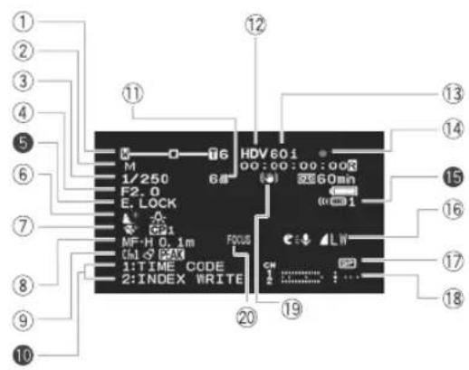
text_image
① ② ③ ④ ⑤ ⑥ ⑦ ⑧ ⑨ ⑩ HDV601 00:00:00:00 68 E. LOCK C21 MF-H 0.1m C31-5 CAX 1:TIME CODE 2:INDEX WRITE 12 13 14 15 16 17 18 19 20 21 22 23 24 25 26 27 28 29 30 31 32 33 34 35 36 37 38 39 40CAMERA·CARD
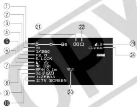
text_image
① ② ③ ④ ⑤ ⑥ ⑦ ⑧ ⑨ ⑩ 21 M 1/250 F2.0 E, LOCK 1 G91 MF+H 0.1m FOCUS G51 G9X 1:ZEBRA 2:TV SCREEN 22 LW C269 23 24 20① Zoom position/Zoom speed (☐ 33)/ Exposure level (☐ 57)
② Programmed AE (☐ 52)
③ Shutter speed* (☐ 55, 57)
④ Aperture* (☐ 56, 57)
⑤ Exposure lock (☐ 58)/ AE shift (☐ 59)
⑥ Sky detail (68)/ White balance (62)
⑦ Skin detail (☐ 67)/Custom preset (☐ 76)
⑧ Manual focus (☐ 36)
⑨ Custom function (☐ 83)/Color correction (☐ 65)/Peaking (☐ 37)
10 Custom keys (70)/ Date and time (26)
⑪ Gain (60)
⑫ Recording standard (31)
⑬ Frame rate (40)
⑭ Tape operation
REC
STOP
OII PAUSE
EJECT
15 Remote sensor mode (☐ 105)
⑯ Microphone mode (☐ 47)/Simultaneous Still image size/quality (☐ 110)
⑰ SD Recording mode (☐ 75)
⑱ Audio level indicator (☐ 49)
⑲ Image stabilizer (☐ 51)
⑳ Magnifying (☐ 37)
② Metering method (117)
②Drive mode (115)
②3 Still image size/quality (110)
② Available still images on the card (110)
* In Manual mode.
** On-screen displays other than those marked in reverse: With the customized displays you can select whether the icons/indicators will appear on the screen or not (90).
VCR/PLAY
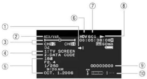
text_image
MIX/VAR. CH17 CH84 Ch1 1:TV SCREEN 2:DATA CODE 18dB F2.4 1/250 9:20 AM OCT. 1,2006 HDV 601 00:05:38:08R 60min 00000000 ① ② ③ ④ ⑤ ⑥ ⑦ ⑧ ⑨ ⑩VCR/PLAY·CARD
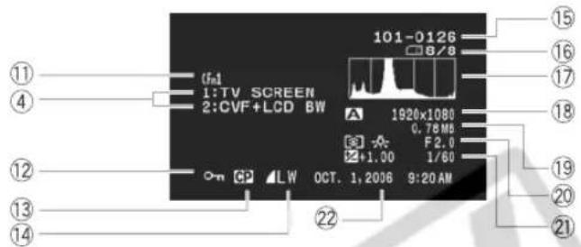
text_image
101-0126 8/8 1920x1080 0.78 MB F2.0 1/60 15 16 17 18 19 20 21 19 22 14 13 12 11 (fa) 1:TV SCREEN 2:CVF+LCD BW O-n 62 LW OCT. 1,2006 9:20 AM① Date search (103)/ Index search (102)/ End search (32)
②Audio output (☐☐ 100)
③ Audio monitor (☐ 100)
④ Custom keys (☐ 70)
⑤ Data code (☐ 104)
⑥ Recording standard (☐ 31)
⑦ Frame rate (☐ 40)
⑧ Tape operation (☐ 95)
● REC
II PAUSE
STOP
EJECT
PLAY
▶ : Fast forward
◀ : Rewind
: Fast forward playback/rewind playback
×2▶/◀×2 : ×2 playback
×1▶/◀×1 : ×1 playback
|►/◄ : Frame advance playback
⑨ User bit (□□ 46)
⑩ Audio level indicator (☐ 49)
⑪ Custom function (☐ 83)
⑫ Image protected (☐ 123)
⑬ Custom preset data embedded with the still image (☐ 81)
⑭ Still image size/quality
⑮ Image number (□ 111)
⑯ Total number of still images (☐ 110)
⑰ Histogram (□ 121)
⑱ Programmed AE (☐ 52)/Still image size (☐ 110)
⑲ Focus (☐ 35)/ File size
⑳ Metering method (☐ 117)/White balance (☐ 62)/Aperture* (☐ 56, 57)
②1 Exposure lock (☐ 58)/ AE shift (☐ 59)/ Shutter speed* (☐ 55, 57)
②2 Date and time of recording
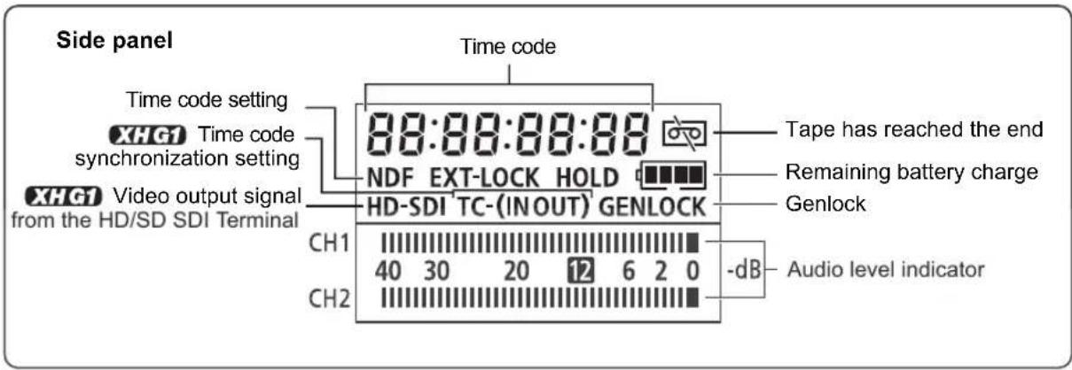
text_image
Side panel Time code Time code setting XHG1 Time code synchronization setting XHG1 Video output signal from the HD/SD SDI Terminal 88:88:88:88 NDF EXT-LOCK HOLD HD-SDI TC-(INOUT) GENLOCK CH1 40 30 20 12 6 2 0 CH2 Time code Tape has reached the end Remaining battery charge Genlock Audio level indicator| Message Explanation | ☐ | |
| SET THE TIME ZONE, DATE AND TIME | You have not set the time zone, date and time. This message appears each time you turn the power on until you set the time zone, date and time. | 26 |
| CHANGE THE BATTERY PACK | Battery pack is exhausted. Replace or charge the battery pack. | 15 |
| THE TAPE IS SET FOR ERASURE PREVENTION | Cassette is protected. Replace the cassette or change the position of the protect switch. | 150 |
| REMOVE THE CASSETTE | Camcorder stopped operating to protect the tape. Remove the cassette and reinsert it. | 23 |
| CHECK THE HDV/DV INPUT | DV cable is not connected, or the connected digital device is turned off. | 106 |
| CONDENSATION HAS BEEN DETECTED | Condensation has been detected in the camcorder. | 148 |
| TAPE END | Tape reached the end. Rewind the tape or replace the cassette. | - |
| HEADS DIRTY, USE CLEANING CASSETTE | Video heads are dirty. Clean the video heads. | 147 |
| NO CARD | Memory card not is inserted into the camcorder. | 24 |
| NO IMAGES | No images are recorded on the memory card. | - |
| CARD ERROR | A memory card error occurred. The camcorder cannot record or play back the image.The error may be temporary. If the message disappears after 4 seconds an “☐” flashes red, turn the camcorder off, remove the card and reinsert the card. If “☐” changes to green, you can continue recording/playback. | - |
| CARD FULL | No remaining capacity on the memory card. Replace with another card or erase images. | - |
| NAMING ERROR | The folder and file numbers have reached their maximum value. | - |
| UNIDENTIFIABLE IMAGE | Image is not recorded with JPEG compression, or with a compression not compatible with the camcorder, or the image file is corrupted. | - |
| THE CARD IS SET FOR ERASURE PREVENTION | SD/SDHC memory card is set for erasure prevention. Replace the card or change the position of the protect switch. | 24 |
| INCORRECT TAPE SPECIFICATION PLAYBACK IS RESTRICTED | You attempted to play back a tape recorded in a standard different than the one to which is the camcorder is set. | - |
| INPUT SIGNAL NOT SUPPORTED | You attempted to input a video signal incompatible with the camcorder (for example 720p). | 106 |
| PLAYBACK STD LOCKED PLAYBACK IS RESTRICTED | When the playback standard is already set in the camcorder, you attempted to play back a tape in a video standard different from that set. | 95 |
| PLAYBACK STD LOCKED INCOMPATIBLE VIDEO INPUT | When the playback standard is already set in the camcorder, you attempted to input a video signal in a standard different from that set. | 106 |
| COPYRIGHT PROTECTED PLAYBACK IS RESTRICTED | You attempted to play back a copyright protected tape. | 107 |
| COPYRIGHT PROTECTED DUBBING RESTRICTED | You attempted to dub a copyright protected tape. May also appear when an anomalous signal is received during analog line-in recording, or during analog-digital conversion of a copyright protected tape. | 107 |
Camcorder Handling Precautions
Do not carry the camcorder by the viewfinder, the LCD panel, the microphone or its cable.
Do not leave the camcorder in places subject to high temperatures, such as a sun-heated car, and high humidity.
Do not use the camcorder in places subject to magnetic or electric fields such as near TV sets, plasma TVs, radio transmitters or portable communication devices.
Do not point the lens or viewfinder at strong light sources. Do not leave the camcorder pointed at a bright subject.
Do not use the camcorder in dusty or sandy places. Dust or sand getting inside the cassette or camcorder may cause damage. Dust and sand can also damage the lens. Attach the lens cap after use.
The camcorder is not waterproof. Water, mud or salt getting inside the cassette or camcorder may cause damage.
○Be careful of heat generated by lighting equipment.
Do not disassemble the camcorder. If the camcorder does not function properly, consult qualified service personnel.
○Handle the camcorder with care. Do not subject the camcorder to shocks or vibration as this may cause damage.
Avoid sudden changes in temperature. Moving the camcorder rapidly between hot and cold temperatures may cause condensation to form on its internal surfaces (☐ 148).
Storage
If you do not intend to use the camcorder for a long time, store it in a place free of dust, with low humidity, and at temperatures not higher than 30 °C (86 °F).
After storage, check the functions of your camcorder to make sure that the camcorder is still working properly.
Cleaning
Camcorder Body and Lens
Use a soft, dry cloth to clean the camcorder body and lens. Never use chemically treated cloth or volatile solvents such as paint thinner.
LCD Screen
○Clean the LCD screen using a commercially available leans cleaning cloth.
○Condensation may form on the surface of the screen when the temperature changes suddenly. Wipe it with a soft dry cloth.
Viewfinder
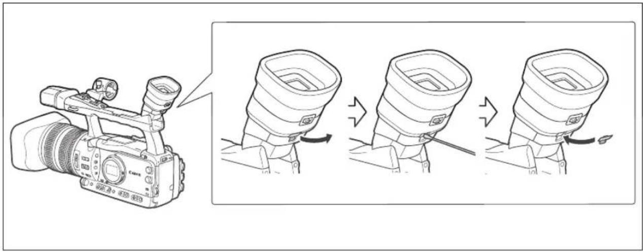
text_image
Diagram showing a camera setup with three stages of tool manipulation, illustrating the process from raw material to final product.- Open the protect cover (e.g. using a flathead screwdriver).
- Clean the glass with a cotton swab.
- Reattach the protect cover.

Be careful not to scratch the glass when cleaning.
Video Heads
When the message "HEADS DIRTY, USE CLEANING CASSETTE" appears, when the playback picture becomes distorted, or if, when playing back a tape in HDV standard, the picture and/or sound stops momentarily (about 0.5 seconds) the video heads need to be cleaned.
To maintain the best picture quality, we recommend cleaning the video heads frequently with the Canon DVM-CL Digital Video Head Cleaning Cassette or a commercially available dry cleaning cassette.
○Tapes already recorded with dirty video heads may not be played back correctly even when you clean the video heads.
Do not use wet type cleaning cassettes as this may damage the camcorder.
If the playback picture does not improve after cleaning the video heads it may indicate a malfunction. Consult a Canon Service Center.
Condensation
Moving the camcorder rapidly between hot and cold temperatures may cause condensation (water droplets) to form on its internal surfaces. Stop using the camcorder if condensation is detected. Continued use may damage the camcorder.
Condensation may form in the following cases:
When the camcorder is moved from an air-conditioned room to a warm, humid place

natural_image
Illustration of a house emitting exhaust with a solar panel emitting smoke, surrounded by trees and sun (no text or symbols)When the camcorder is left in a humid room
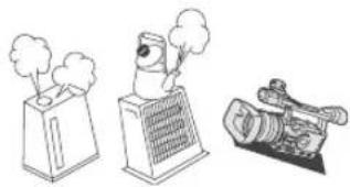
natural_image
Illustration of three industrial devices: a gas stove emitting smoke, a fan-shaped device emitting exhaust, and a video camera (no text or symbols)When the camcorder is moved from a cold place to a warm room
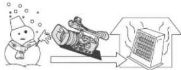
natural_image
Illustration of a snowman blowing bubbles, a camera, and a computer monitor (no text or symbols)When a cold room is heated rapidly
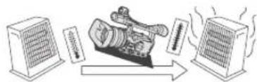
flowchart
graph LR
    A["Server Unit 1"] --> B["Camera"]
    B --> C["Server Unit 2"]
    C --> D["Data Flow"]
    D --> E["Output"]
How to avoid condensation:
☐Unload the cassette, place the camcorder in an airtight plastic bag and let it adjust to temperature changes slowly before removing it from the bag.
When condensation is detected:
The camcorder stops operating, and the warning message "CONDENSATION HAS BEEN DETECTED" appears for approx. 4 seconds and "◀" starts flashing.
If a cassette is loaded, the warning message "CONDENSATION HAS BEEN DETECTED REMOVE THE CASSETTE" appears and "☐" starts flashing. Remove the cassette immediately and leave the cassette compartment open. Leaving the cassette in the camcorder may damage the tape.
OA cassette cannot be loaded when condensation is detected.
Resuming use:
It takes about 1 hour until the water droplets evaporate. After the condensation warning stops flashing, wait for 1 more hour before resuming use.
DANGER!
Treat the battery pack with care.
- Keep it away from fire (or it might explode).
- Do not expose the battery pack to temperature higher than 60^ (140°F). Do not leave it near a heater or inside a car in hot weather.
- Do not try to disassemble or modify it.
- Do not drop or knock it.
- Do not get it wet.
○Charged battery packs continue to discharge naturally. Therefore, charge them on the day of use, or the day before, to ensure a full charge.
Attach the terminal cover whenever a battery pack is not in use. Contact with metallic objects may cause a short circuit and damage the battery pack.
- Dirty terminals may cause a poor contact between the battery pack and the camcorder. Wipe the terminals with a soft cloth.
○Since storing a charged battery pack for a long time (about 1 year) can shorten its lifecycle or affect performance, we recommend to discharge the battery pack fully and to store it in a dry place at temperatures no higher than 30 °C (86 °F). If you do not use the battery pack for long periods, charge and discharge it fully at least once a year. If you have more than 1 battery pack, perform these precautions at the same time for all battery packs.
Although the battery pack's operating temperature range is from 0 °C to 40 °C (32 °F to 104 °F), the optimal range is from 10 °C to 30 °C (50 °F to 86 °F). At cold temperatures, performance will temporarily decline. Warm it in your pocket before use.
○Replace the battery pack if the usable time after full charge diminishes substantially at normal temperatures.
About the battery terminal cover
The battery terminal cover has a [☐]-shaped hole. This is useful when you wish to differentiate between charged and uncharged battery packs. For example, with charged battery packs, attach the terminal cover so that the [☐]-shaped hole shows the blue label.
Back side of the battery pack
Terminal cover attached
Charged
Uncharged
Cassette Handling Precautions
○Rewind tapes after use. If the tape is lose or damaged, it may cause picture and sound distortion.
- Return cassettes to their case and store them upright. Rewind tapes from time to time if they are stored for a long time.
Do not leave the cassette in the camcorder after use.
Do not use spliced tapes or nonstandard cassettes as they may damage the camcorder.
Do not use tapes that have been jammed as video heads may become dirty.
Do not insert anything into the small holes of the cassette, or cover them with cellophane tape.
○Handle cassettes with care. Do not drop or subject them to severe impact as this may damage the cassettes.
With cassettes equipped with a memory function, metal plated terminals may become dirty with use. Clean the terminals with a cotton swab after about 10 times of loading/unloading. The memory function is not supported by the camcorder.
Protecting Tapes from Accidental Erasure
To protect your recordings from accidental erasure, slide the tab on the cassette to the left. (This switch position is usually labeled SAVE or ERASE OFF.)
If you load a protected cassette in recording mode, the message "THE TAPE IS SET FOR ERASURE PREVENTION" appears for approx. 4 seconds and "☐" starts flashing. If you wish to record on that cassette, slide the tab back to the right.
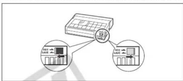
text_image
Diagram illustrating a car air conditioner system with two input devices and one output device, showing internal circuitry.Memory Card
To transfer the still images recorded on the memory disc to a computer, use a commercially available card reader or PC/PCMCIA memory card adapter.
Initialize new memory cards with the camcorder. Memory cards initialized with other devices such as a computer may not operate correctly.
We recommend saving backups of memory card images on your computer's hard drive or other external memory device. Image data may be corrupted or lost due to memory card defects or exposure to static electricity. Canon Inc. makes no warranties for corrupted or lost data.
- Do not use memory cards in places subject to strong magnetic fields.
- Do not leave memory cards in places subject to high humidity and high temperature.
○Do not disassemble memory cards.
Do not bend, drop, or subject memory cards to shocks and do not expose them to water.
○ Moving a memory card rapidly between hot and cold temperatures may cause condensation to form on its external and internal surfaces. If condensation forms on the card, put it aside until the droplets have evaporated completely.
Do not touch or expose the terminals to dust or dirt.
☐Check the direction before inserting the memory card. Forcing a memory card backwards into the slot may damage the memory card or the camcorder.
Do not remove the label from the memory card, or affix other labels on the memory card.
When you erase image files or initialize the memory card, only the file allocation table is altered and the data itself is not actually deleted. Take the necessary precautions when you dispose of the memory card, for example by physically damaging it to prevent the leakage of private data.
Using the Camcorder Abroad
Power Sources
You can use the compact power adapter to operate the camcorder and to charge battery packs in any country with power supply between 100 and 240 V AC, 50/60 Hz. Consult the Canon Service Center for information on plug adapters for overseas use.
Playback on a TV Screen
You can only play back your recordings on TVs with NTSC system. The NTSC system is used in the following countries/areas:
American Samoa, Antigua, Aruba, Bahamas, Barbados, Bermuda, Bolivia, Canada, Chile, Colombia, Costa Rica, Cuba, Ecuador, El Salvador, Guam, Guatemala, Greenland, Haiti, Honduras, Jamaica, Japan, Korea, Mexico, Micronesia, Myanmar, Nicaragua, Panama, Peru, Philippines, Puerto Rico, Saint Kitts and Nevis, Saint Lucia, Saint Vincent and the Grenadines, Surinam, Taiwan, Trinidad and Tobago, USA, Venezuela, Virgin Islands.

If you have a problem with your camcorder, refer to this checklist. Consult your dealer or a Canon Service Center if the problem persists.
Power Source
| Problem Cause Solution | ☐ | ||
| Camcorder will not turn on. Battery pack is not correctly attached. Attach the battery pack correctly. 15 | |||
| The camcorder switches off by itself. | Power save function has been activated. | Turn on the camcorder. | 28 |
| The screen switches on and off. | Battery pack is exhausted. | Replace or charge the battery pack. | 15 |
Recording/Playback
| Problem | Cause | Solution | |
| Buttons will not work. | Cassette is not loaded. | Load a cassette. | 23 |
| “☐” flashes on the screen. | Condensation is detected. | See reference page. | 148 |
| “REMOVE THE CASSETTE” appears on the screen. | Camcorder stopped operating to protect the tape. | Remove the cassette and reinsert it. | 23 |
| The wireless controller will not work. | Camcorder and wireless controller are not set to the same remote sensor mode. | Change the remote sensor modes. | 105 |
| Batteries of the wireless controller are exhausted. | Replace the batteries. | 22 | |
| Abnormal characters appear on the screen. The camcorder does not operate properly. | This camcorder uses a microcomputer. External noise or static electricity may cause abnormal characters to appear on the screen. | Disconnect the power source and reconnect it after a short time. If the problem still persists, disconnect the power source and press the RESET button with a pointed item. Pressing the RESET button resets all settings. | - |
Recording
| Problem | Cause | Solution | |
| The POWER dial is not in the OFF position but the POWER indicator is off. | The LED indicators option in the customized functions is set to [02 OFF]. | Set the [LED] setting to one of the other types. | 89 |
| The STANDBY lever is at the LOCK position. | Turn the STANDBY lever to the STANDBY position. | 28 | |
| Image will not appear on the screen. | The POWER dial is not set to a recording program. | Set the POWER dial to a recording program. | 27 |
| “SET THE TIME ZONE, DATE AND TIME” appears on the screen. | Time zone, date and time are not set, or the built-in rechargeable lithium battery is exhausted. | Set the time zone, date and time. If necessary, power the camcorder with the compact power adapter and leave it connected with the POWER dial set to OFF for at least 24 hours to recharge the built-in battery before making the settings. | 26 |
| Pressing the start/stop button will not start recording. | Cassette is not loaded. | Load a cassette. | 23 |
| The POWER dial is not set to a recording program. | Set the POWER dial to a recording program. | 27 | |
| The lock switch is set to prevent the operation of the controls on the carrying handle. | Slide the lock switch to the left to enable the operation of the carrying handle controls. | 28 | |
| Camcorder will not focus. | Autofocus does not work on that subject. | Focus manually. | 36 |
| Viewfinder is not adjusted. | Adjust the viewfinder with the dioptric adjustment lever. | 18 | |
| Lens is dirty. | Clean the lens. | 146 | |
| The tally lamp will not light up. | The tally lamp option in the customized functions is set to [02 OFF]. | Set the [TALLY LAMP] setting to [ON] or [BLINK]. | 89 |
Recording
| Problem Cause Solution | ☐ | ||
| A vertical light bar appears on the screen. | Bright light in a dark scene may cause a vertical light bar (smear) to appear. This is not a malfunction. | Record in the Av mode with F5.6–F8.0. | 56 |
| Viewfinder picture is blurred. Viewfinder is not adjusted. Adjust the viewfinder with the dioptric adjustment lever. | 18 | ||
| Audio is not recorded. The input channel selection switch is not set to the correct position. | Set the input channel selection switch to the correct position. | 48 | |
| Even though you are using the built-in microphone, [XLR INPUT] is set to [ON ➔ XLR]. | 48 | ||
| Microphone connected to the XLR terminal needs to be powered by the phantom power. | 48 | ||
| Audio is recorded in a very low level. | The AUDIO LEVEL switch is set to M, and recording level is set too low. | Adjust the audio level correctly. | 49 |
| Microphone attenuator is turned on. | Set the MIC ATT. switch or the XLR MIC ATT switch to OFF. | 49 | |
Playback
| Problem | Cause | Solution | |
| Pressing the playback button does not start playback. | Camcorder is turned off, or is not set to VCR/PLAY mode. | Set the camcorder to VCR/PLAY mode. | 95 |
| Cassette is not loaded. | Load a cassette. | 23 | |
| Tape is running, but image will not appear on the TV screen. | Video heads are dirty. | Clean the video heads. | 147 |
| You attempted to play back or dub a copyright protected tape. | Stop playback/dubbing. | - | |
| The video output cable is not connected correctly. | Verify that the video cable is connected properly. | - | |
| While playing back a tape recorded in HDV standard there are brief stops in the playback picture. | Video heads are dirty. | Clean the video heads with a dry cleaning cassette. | 147 |
Memory Card Operations
| Problem | Cause | Solution | ☐ |
| Memory card cannot be inserted. | Memory card was not facing the correct direction. | Turn the memory card over and reinsert it. | 24 |
| Memory card cannot be recorded. | No memory card. | Insert a memory card. | 24 |
| Memory card is full. | Replace the memory card or erase images. | 122 | |
| Memory card is not initialized. | Initialize the memory card. | 124 | |
| The folder and file numbers have reached their maximum value. | Set [FILE NOS.] to [RESET] and insert a new memory card. | 111 | |
| Memory card cannot be played back. | The POWER dial or ☐/☐ (card/tape) switch are not set to the correct position. | Set the POWER dial to VCR/PLAY and the ☐/☐ (card/tape) switch to ☐. | 120 |
| Image cannot be erased. | Image is protected. | Cancel the protection. | 123 |
| On an SDHC or SD memory card, the write-protect switch is set to the locked position. | Change the position of the write-protect switch on the memory card to unlock it. | ||
| “☐” flashes red. | Card error occurred. | Turn off the camcorder. Remove and reinsert the memory card. Initialize the memory card if flashing persists. | 124 |
About the LCD screen
The LCD screen is produced with extremely high-precision manufacturing techniques, with more than 99.99% of the pixels operating to specification. Less than 0.01% of the pixels may occasionally misfire or appear as black, red, green or blue dots. This has no effect on the recorded image and does not constitute a malfunction.
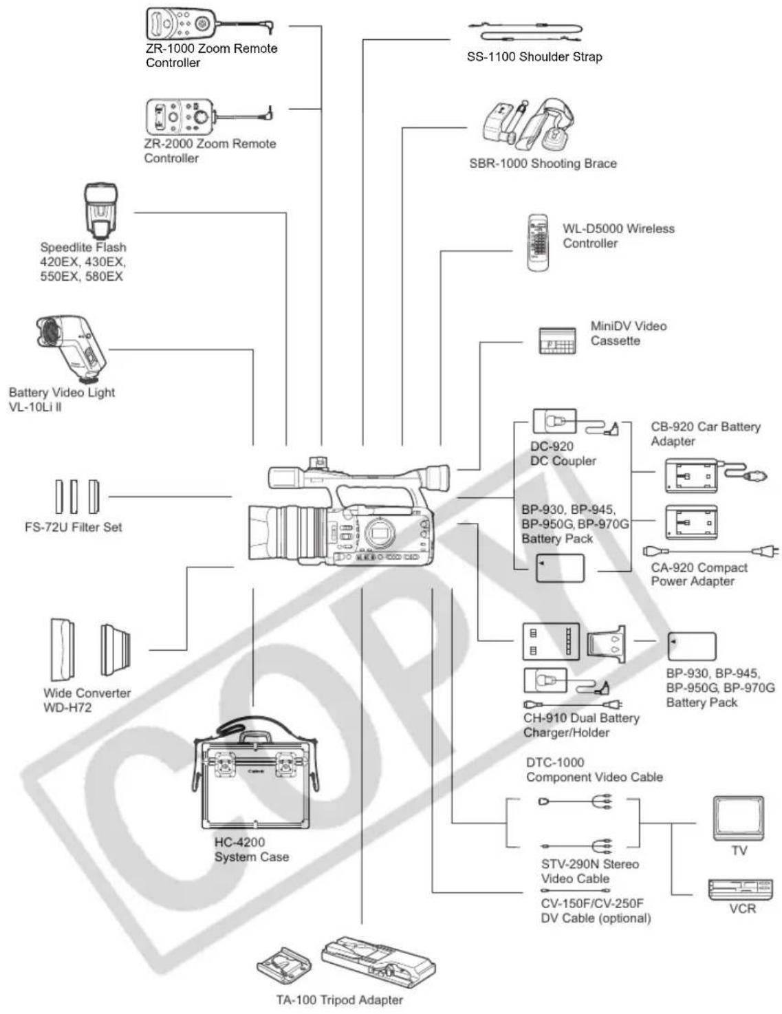
flowchart
graph TD
    A["Camera"] --> B["ZR-1000 Zoom Remote Controller"]
    A --> C["ZR-2000 Zoom Remote Controller"]
    A --> D["Speedlite Flash 420EX, 430EX, 550EX, 580EX"]
    A --> E["Battery Video Light VL-10Li II"]
    A --> F["FS-72U Filter Set"]
    A --> G["Wide Converter WD-H72"]
    A --> H["HC-4200 System Case"]
    A --> I["TA-100 Tripod Adapter"]
    A --> J["SS-1100 Shoulder Strap"]
    A --> K["SBR-1000 Shooting Brace"]
    A --> L["WL-D5000 Wireless Controller"]
    A --> M["MiniDV Video Cassette"]
    A --> N["DC-920 DC Coupler"]
    N --> O["BP-930, BP-945, BP-950G, BP-970G Battery Pack"]
    N --> P["CB-920 Car Battery Adapter"]
    N --> Q["CA-920 Compact Power Adapter"]
    A --> R["CH-910 Dual Battery Charger/Holder"]
    R --> S["BP-930, BP-945, BP-950G, BP-970G Battery Pack"]
    A --> T["DTC-1000 Component Video Cable"]
    T --> U["STV-290N Stereo Video Cable"]
    U --> V["CV-150F/CV-250F DV Cable (optional)"]
    T --> W["TV"]
    T --> X["VCR"]
Call or visit your local retailer/dealer for genuine Canon video accessories. You can also obtain genuine accessories for your Canon camcorder by calling: 1-800-828-4040, Canon U.S.A. Information Center.
Use of genuine Canon accessories is recommended.
This product is designed to achieve excellent performance when used with genuine Canon accessories. Canon shall not be liable for any damage to this product and/or accidents such as fire, etc., caused by the malfunction of non-genuine Canon accessories (e.g., a leakage and/or explosion of a battery pack). Please note that this warranty does not apply to repairs arising out of the malfunction of non-genuine Canon accessories, although you may request such repairs on a chargeable basis.
Battery Packs
The BP-950G is also available as an optional accessory. The optional BP-970G provides over 35% more recording time than the BP-950G.
Car Battery Adapter CB-920
Use the car battery adapter to power the camcorder or charge battery packs on the move. The car battery adapter plugs into your car's cigarette lighter socket and runs off a 12-24V DC negative ground battery.
FS-72U Filter Set
Ultraviolet, neutral density and circular polarizing filters to help you take control of difficult lighting conditions.
HC-4200 System Case
A solid, lockable case that provides safe and stylish protection for the camcorder during transportation and storage.
TA-100 Tripod Adapter
The TA-100 allows you to quickly mount/unmount the XH G1/XH A1 on/from a tripod.
SBR-1000 Shooting Brace
Using the SBR-1000 for additional support of the video camera with the neck strap will significantly lighten the load of the camera's weight while shooting.
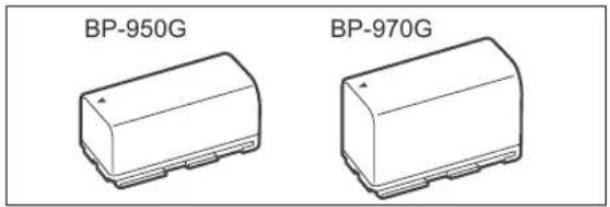
text_image
BP-950G BP-970G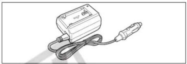
natural_image
Line drawing of a handheld electronic device with coiled cable and connector (no text or symbols)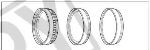
natural_image
Three technical line drawings of cylindrical mechanical components with no visible text or symbols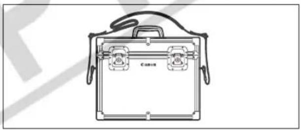
natural_image
Line drawing of a Canon hard-shell briefcase with handles and internal compartments (no text or symbols)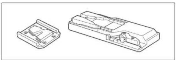
natural_image
Technical line drawing of two mechanical components: a flange and a housing (no text or symbols)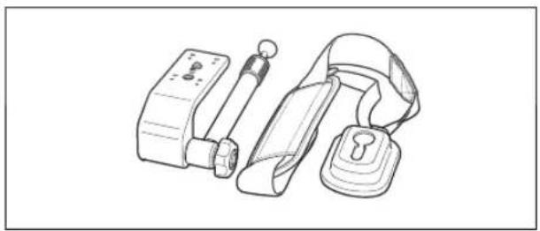
natural_image
Line drawing of a mechanical device with a strap, handle, and lock (no text or symbols)CH-910 Dual Battery Charger/Holder
The CH-910 can charge two battery packs consecutively. You can also power the camcorder by connecting the CH-910 with charged battery packs to the camcorder. When you attach two battery packs, a battery pack can be exchanged without interrupting the power supply.
| Battery Pack Charging Time | |
| BP-950G | 280 min. |
| BP-970G | 380 min. |
Charging time varies according to the charging condition.
ZR-2000 Zoom Remote Controller
When the ZR-2000 is connected to the LANC terminal of a Canon camcorder, it is possible to control functions such as the start and stop of recording, the zoom and the focus functions while reviewing the picture on the local display without touching the camcorder. This is particularly useful while the camcorder is mounted on a tripod and you want to ensure maximum stability of a shot.
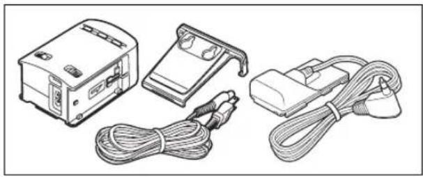
natural_image
Illustration of four electronic devices: a front-mounted device, a connector, and a cord with cables (no text or symbols visible)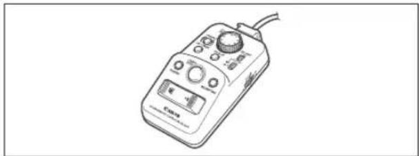
natural_image
Line drawing of a handheld electronic device with control knobs and a display (no text or symbols)
This mark identifies genuine Canon video accessories. When you use Canon video equipment, we recommend Canon-brand accessories or products bearing the same mark.
Provided accessories: Optional accessories:
CA-920 Compact Power Adapter 8029A002AA
DC-920 DC Coupler 8033A001AA
BP-950G Battery Pack 0971B002AA
SS-1100 Shoulder Strap D81-1510-000
WL-D5000 Wireless Controller D83-0730-000
Adapter holder D82-0780-000
DTC-1000 Component Video Cable D82-0820-000
STV-290N Stereo Video Cable
D82-0880-000
BP-970G Battery Pack 0972B002AA
CB-920 Car Battery Adapter 8034A002AA
CH-910 Dual Battery Charger/Holder 3036A002AA
ZR-2000 Zoom Remote Controller 0973B002AA
TA-100 Tripod Adapter 9859A001AA
FS-72U Filter Set 3093A002AA
WD-H72 Wide Converter 1724B001AA
HC-4200 System Case
1723B001AA
DVM-CL DV Cleaning Cassette
3134A002AA

XH G1 / XH A1
System
| Video Recording System Rotary head, helical scanning, digital component recording | |
| HDV High Definition Video 1080iDV Consumer digital VCR SD system | |
| Audio Recording System | HDV MPEG-1 audio layer 2, 16 bit (48 kHz), Transfer rate: 384 kbps (2CH)DV PCM digital sound, 16 bit (48 kHz) or 12 bit (32 kHz) |
| Television System | HD High Definition Video (HDV) 1080/60iSD EIA standard (525 lines, 60 fields) NTSC color signal |
| Image Sensor | 1/3-inch CCD x 3 (horizontal pixel shift), approx. 1,670,000 pixelsEffective pixels: [HDV] approx. 1,560,000[SD16:9] approx. 1,560,000[SD4:3] approx. 1,170,000 |
| Tape Format | Videocassettes bearing the "MiniDV" mark. |
| Tape Speed | HDV 18.81 mm/s (0.74 ips)DV SP: 18.81 mm/s (0.74 ips), LP: 12.56 mm/s (0.49 ips) |
| Maximum Recording Time(60 min. cassette) | HDV 60 min.DV SP: 60 min., LP: 90 min. |
| Fast Forward/Rewind Time | Approx. 2 min. 20 sec. (with a 60 min. cassette) |
| Viewfinder | 0.57 in. wide, 16:9 aspect ratio TFT color, approx. 269,000 pixels |
| LCD Screen | 2.8 in. wide, 16:9 aspect ratio TFT color, approx. 207,000 pixels |
| Microphone | Stereo electret, Cross-layout microphone |
| Lens | f=4.5-90 mm, F/1.6-3.5, 20x power zoom35 mm equivalent:[HD], [SD16:9], 16:9 still images: approx. 32.5-650 mm[SD4:3], 4:3 still images: approx. 39.8-796 mm |
| Lens Configuration | 16 elements in 11 groups (1 aspheric element) |
| Filter Diameter | 72 mm |
| AF system | Autofocus, manual focusing with focus ring |
| White Balance | Auto white balance, pre-set white balance (indoor, outdoor), custom white balance, or color temperature setting |
| Minimum Illumination | 0.4 lx (60i/30F mode, Manual mode, 1/4 shutter, F1.6, Gain 18 dB) |
| Recommended Illumination | More than 100 lx (60i/30F) |
| Image Stabilization | Optical Shift Image Stabilizer |
| Memory Card | |
| Recording media | SDHC (SD High Capacity) memory card, SD memory card, MultiMedia Card (MMC)* |
| Size of Images on the Card | 1920 x 1080, 1440 x 1080, 848 x 480, 640 x 480 pixels |
| File Format | Design rule for Camera File system (DCF), Exif 2.2** compliant, DPOF compliant |
| Image Compression Method | JPEG compression (Super Fine, Fine, Normal) |
* The camcorder's operations have been tested with SD memory cards up to 2 GB. Performance cannot be guaranteed for all memory cards.
** The camcorder supports Exif 2.2 (also called "Exif Print"). Exif Print is a standard for enhancing the communication between camcorders and printers. By connecting to an Exif Print-compliant printer, the camcorder's image data at the time of shooting is used and optimized, yielding extremely high quality prints.
Input/Output Terminals
| Video Terminals | A/V1:ø 3.5 mm mini jack (audio and video), V2: BNC jack (video only)1 Vp-p/75 ohms unbalanced |
| Audio Out Terminals A/V1: | ø 3.5 mm mini jack (audio and video)-10 dBV 47 kohm load/3 kohms or less, unbalanced |
| Audio In Terminals MIC: | ø 3.5 stereo mini jack (unbalanced), ATT: 20 dB-64 dBV (Auto mode)/600 ohmsMax: -76 dBV (Manual mode, max. volume)A/V1:ø 3.5 mm mini jack (audio and video)-10 dBV /47 kohmsXLR:XLR jack (pin1: shield, pin2: hot, pin3: cold), ATT: 20 dB-59.5 dBV (Auto mode)/600 ohms (LINE/MIC switch set to MIC)6 dBV (Auto mode)/10 kohms (LINE/MIC switch set to LINE)Max 1: -71.5 dBV (Auto mode, XLR GAIN UP at 12 dB)Max 2: -71.5 dBV (Manual mode, max. volume)Max 3: -83.5 dBV (Manual mode, max. volume, XLR GAIN UP at 12 dB) |
| HDV/DV Terminal | Special 4-pin connector (IEEE1394 compliant) input/output |
| ΩHeadphone Terminal | ø 3.5 mm stereo mini-jack, -23.5 dBV (16 ohm load)/50 ohms |
| LANC Terminal | ø 2.5 mm stereo mini-jack |
| XHG1GENLOCK Terminal | BNC jack, input : 1 Vp-p/75 ohms |
| XHG1TIME CODE Terminal | BNC jack, input : 0.5 V–18 Vp-p/10 kohmsoutput : 1 Vp-p/75 ohms |
| XHG1HD/SD-SDI Terminal | BNC jack, output only, 0.8 Vp-p/75 ohms, unbalancedSDI 480/60i: SMPTE 259M, SMPTE 272M, SMPTE RP 188 (LTC)HD-SDI: SMPTE 292M, SMPTE 299M, SMPTE RP 188 (LTC) |
| COMPONENT OUT Terminal | 1080i (D3)/480i (D1) compatible |
Power/Others
| Power supply (rated) | 7.4 V (battery pack) |
| Power consumption | Recording with autofocus, HD mode:XHG1 Viewfinder [NORMAL]: 7.1 W, LCD screen [NORMAL]: 7.3 WXHA1 Viewfinder [NORMAL]: 6.7 W, LCD screen [NORMAL]: 6.9 W |
| Operating temperature | 0 – 40 °C (32 – 104 °F) |
| Dimensions (W x H x D) | 163 x 189 x 350 mm (6.4 x 7.4 x 13.8 in.) excluding the gripbelt |
| Weight | XHG1 2,100 g (4.6 lb.)XHA1 2,030 g (4.5 lb.) |
CA-920 Compact Power Adapter
| Power supply | 100 – 240 V AC, 50/60 Hz |
| Power consumption | 24 W |
| Rated output | Adapter: 7.2 V DC, 2.0 A, Charger: 8.4 V DC, 1.5 A |
| Operating temperature | 0 – 40 °C (32°– 104 °F) |
| Dimensions | 75 x 99 x 51 mm (3.0 x 3.9 x 2.0 in.) |
| Weight | 215 g (7.6 oz.) without power cable |
BP-950G Battery Pack
| Battery type | Rechargeable lithium ion battery |
| Rated voltage | 7.4 V DC |
| Operating temperature | 0 – 40 °C (32°– 104 °F) |
| Battery capacity | 5,200 mAh |
| Dimensions | 38.2 x 40.3 x 70.5 mm (1.5 x 1.6 x 2.8 in.) |
| Weight | 210 g (7.4 oz.) |
Weight and dimensions are approximate. Errors and omissions excepted. Subject to change without notice.
A
Abroad, using the camcorder .....151
Accessories 9,155
AE shift 59
AEB - Auto exposure bracketing ..... 116
Analog/digital (A/D) converter 108
Aspect guides 30
Aspect ratio 31
Audio level indicator 49
Audio mode (SD) 47
Audio output (SD) 100
Audio recording 47
Audio reference signal 73
Auto (recording program) 52
Autofocus (AF) mode 35
Av (recording program) 56
B
Battery pack 15
Black level 76
Built-in backup battery 16
C
Clear scan 69
Color bars 73
Color correction 65
Color gain 77
Color matrix 77
Color phase 78
COMPONENT OUT terminal 98
Component video 98
Condensation 148
Connection to a computer 109
Connection to a High Definition TV (HDTV) 97
Connection to a TV/VCR 97, 99
Continuous Shooting 115
Coring 77
Custom keys 70
Custom preset settings 76
Customized displays 90
Customized functions 83
D
Data code 104
Date and time 26
Date format 75
Date search 103
DC coupler 16
Drive mode 115
Drop frame (time code) 42
DV control 74
E
Easy recording (recording program) 52
End search 32
Erasing still images 122
Error messages 145
Exposure 58
External synchronizations* 44
External video, analog line-in....106
External video, HDV/DV in ....106
F
File numbers 111
Flash 118
Focus 35
Focus preset 37
Frame rate 40
Free-run (time code) 42
G
Gain 60
Gamma 76
Genlock ^* 44
Grip belt 20
H
HD/SD SDI terminal* 97
HD/SD video signal standards 6
HDV/DV tape recording standards 6
HDV/DV terminal 98,106,109
I
Image jump 121
Image stabilizer 51
Index search 102
Index write 71
Initialization - Memory card 124
K
Knee 76
L
Language 75
LCD screen 19
LCD side panel 144
Lens hood 21
Low-angle recording 28
M
Maintenance 146
Manual (recording program) 57
Manual focus 36
Master pedestal 77
Memory card 24,150
MENU settings 127
Microphone 48
Microphone attenuator 49
Mix balance 100
N
ND filter 39
Night (recording program) 53
Non-drop frame (time code) 42
NR 77
P
Peaking and Magnifying (focus assist) 37
Phantom power (microphone) 48
Playback - Movies 95
Playback - Still images 120
Power adapter 15
POWER dial 10
Power save 28
Print order 125
Programmed AE 52
Protecting still images 123
Pulldown mode (24F frame rate) 41
R
Record review....30
Recording - Movies 27
Recording - Still images 112
Recording mode (SD) 75
Recording programs 52
Rec-run (time code) 42
Rec-run preset (time code) 42
Remaining battery indication 29
Remaining tape indication 29
Remote sensor 22
S
Safety zone 30
Screen displays 90
Screen markers 30
SD memory card 24
Setup level 77
Sharpness 77
Shoulder strap 20
Shutter speed 55
Signal standard 31
Simultaneous recording (tape/memory card) .....113
Skin detail 67
Sky detail 68
Slideshow 120
Specifications 158
Spotlight (recording program) 53
Still image quality 110
Still image review 119
Still image size 110
T
Tape protection 150
Temporary autofocus 36
Time code 42
Time code synchronization* 44
Troubleshooting 152
Tv (recording program) 55
U
User bit 46
V
VCR Stop 28
Video heads, cleaning 147
Videocassettes 23,150
Viewfinder 18
W
White balance 62
Wireless controller 22
Z
Zebra pattern 64
Zero set memory 101
Zoom 33
Zoom preset 34
Zoom speed 33
Custom Keys
Make a copy of this page and carry it with you as a reminder of the functions that can be assigned to each of the two custom keys in each operation mode.
You can assign frequently used functions to the custom keys. The custom keys can have different functions assigned to them in each of the operation modes.
Default settings:
| CAMERA | VCR/PLAY | CAMERA·CARD | VCR/PLAY·CARD | |
| CUSTOM KEY 1 | TIME CODE | TV SCREEN | ZEBRA | TV SCREEN |
| CUSTOM KEY 2 | INDEX WRITE | DATA CODE | TV SCREEN | CVF+LCD BW |
The following functions can be assigned to the custom keys:
| CAMERA | VCR/PLAY | |
| Time codeIndex write ^2 Zebra patternVCR stop ^2 TV screen | Time code hold ^2 Audio levelCVF+LCD BWMAGN. buttonSHUTTER dialCP backward key ^1,2 | Time codeTV screenData codeAudio levelTime code hold ^2 CVF+LCD BW |
| CAMERA·CARD | VCR/PLAY·CARD | |
| Zebra patternTV screenCVF+LCD BWMAGN. buttonSHUTTER dialCP backward key ^1,2 | TV screenCVF+LCD BW | |
^1 Can only be assigned to Custom Key 2.
^2 This function can only be operated with a custom key (Index write can also be operated with the wireless controller).
U.S.A.
CANON CONSUMER DIGITAL VIDEO EQUIPMENT LIMITED WARRANTY FOR THE UNITED STATES
The warranty set forward below is given by Canon U.S.A., Inc. with respect to equipment purchased in the
United States. The limited warranty is only effective upon presentation of your Bill of Sale or other proof of purchase.
Canon consumer digital video equipment is warranted under normal, non-commercial, personal use, against defective materials or workmanship as follows:
Parts: Defective parts will be exchanged for new parts or comparable rebuilt parts for a period of ONE YEAR from the date of original purchase, except for a defective Video Head,
which will be exchanged for a period of three months from the date of purchase.
Labor: For a period of ONE YEAR from the date of original purchase, labor will be provided free of charge by our factory service centers or designated service facilities located in the United States.
When returning equipment under this warranty, you must pre-pay the shipping charges, and you must enclose the Bill of Sale or other proof of purchase with a complete explanation of the problem. During your ONE-YEAR warranty period, repairs will be made and the equipment return-shipped to you free of charge. After your warranty period is over, you will be given an estimate of the cost of repair and an opportunity to approve or disapprove of the repair expense before it is incurred. If you approve, repairs will be made and the equipment return-shipped to you. (shipping charges apply). If you disapprove, we will return-ship the equipment at no charge to you.
Non-Canon brand peripheral equipment and software which may be distributed with Canon DV camcorders are sold "AS IS" without warranty of any kind by CUSA, including any implied warranty regarding merchantability or fitness for a particular purpose. The sole warranty with respect to such non-Canon brand items is given by the manufacturer or producer thereof.
CUSA shall have no responsibility under this limited warranty for use of Canon DV Camcorders in conjunction with incompatible peripheral equipment and incompatible software.
In order to obtain warranty service, contact the authorized Canon retail dealer from whom you purchased the DV Camcorder or call the CANON INFORMATION CENTER AT 1-800-828-4040). You will be directed to the nearest service facility for your product.
This Limited Warranty covers all defects encountered in normal use of the equipment and does not apply in the following cases:
A) Loss or damage to the equipment due to abuse, mishandling, accident, improper maintenance, or failure to follow operating instructions;
B) If the equipment is defective as a result of leaking batteries, sand, dirt or water damage;
C) If defects or damages are caused by the use of unauthorized parts or by service other than our authorized agent;
D) If the equipment is used for commercial or industrial use.
This Limited Warranty does not cover cabinet (exterior finish), video cassette tape, head cleanings, nor does it apply to equipment purchased outside the United States. This warranty does not cover units sold to rental firms, military operations, hotels, schools, hospitals or for other commercial, industrial, or institutional applications. These uses are covered only by such specific warranty as Canon may issue with such sales.
This Limited Warranty does not apply to accessories or consumables for the DV Camcorder, which are sold "AS IS", without warranty of any kind by CUSA.
Please retain this warranty card and your Bill of Sale as a permanent record of your purchase. This card is most important in order to be sure you are contacted right away should there be a safety inspection, modification or product recall under applicable laws or regulations.
NO IMPLIED WARRANTY, INCLUDING MERCHANTABILITY AND FITNESS FOR A PARTICULAR PURPOSE APPLIES TO THIS EQUIPMENT AFTER THE APPLICABLE PERIOD OF EXPRESS WARRANTY OR GUARANTY, EXCEPT AS MENTIONED ABOVE, GIVEN BY ANY PERSON, FIRM OR CORPORATION WITH RESPECT TO THIS EQUIPMENT SHALL BIND THE UNDERSIGNED. (SOME STATES DO NOT ALLOW LIMITATIONS ON HOW LONG AN IMPLIED WARRANTY LASTS, SO THE ABOVE LIMITATION OR
EXCLUSION MAY NOT APPLY TO YOU). CUSA SHALL NOT BE LIABLE FOR LOSS OF REVENUES OR PROFITS, EXPENSE FOR SUBSTITUTE EQUIPMENT OR SERVICE, STORAGE CHARGES, LOSS OF DATA, OR ANY OTHER SPECIAL, INCIDENTAL OR CONSEQUENTIAL DAMAGES CAUSED BY THE USE, MISUSE OR INABILITY TO USE THE DV CAMCORDER, REGARDLESS OF THE LEGAL THEORY ON WHICH THE CLAIM IS BASED, AND EVEN IF CUSA HAS BEEN ADVISED OF THE POSSIBILITY OF SUCH DAMAGES. NOR SHALL RECOVERY OF ANY KIND AGAINST CUSA BE GREATER THAN THE PURCHASE PRICE OF THE DV CAMCORDER SOLD BY CUSA AND CAUSING THE ALLEGED DAMAGE. WITHOUT LIMITING THE FOREGOING, YOU ASSUME ALL RISK AND LIABILITY FOR LOSS, DAMAGE OR INJURY TO YOU AND YOUR PROPERTY AND TO OTHERS AND THEIR PROPERTY ARISING OUT OF USE, MISUSE OR INABILITY TO USE THE DV CAMCORDER NOT CAUSED DIRECTLY BY THE NEGLIGENCE OF CUSA. (SOME STATES DO NOT ALLOW THE EXCLUSION OR LIMITATION OF INCIDENTAL OR CONSEQUENTIAL DAMAGES, SO THE ABOVE LIMITATION MAY NOT APPLY TO YOU). THIS WARRANTY SHALL NOT EXTEND TO ANYONE OTHER THAN THE ORIGINAL PURCHASER OF THIS EQUIPMENT OR THE PERSON FOR WHOM IT WAS PURCHASED AS A GIFT.
This warranty gives you specific legal rights, and you may also have other rights which vary from state to state. CANON U.S.A., INC.
CANADA
CANON CONSUMER DIGITAL VIDEO EQUIPMENT LIMITED WARRANTY
The limited warranty set forth below is given by Canon Canada Inc. ("Canon Canada") with respect to Canon digital video equipment purchased in Canada. This limited warranty is only effective upon presentation of a bill of sale or other proof of purchase for this Canon digital video equipment to a Canon Service Facility when repairs are required.
Canon consumer video digital equipment is warranted under normal, non-commercial, personal use, against defective materials or workmanship as follows:
Parts: Defective parts will be exchanged for new parts or, at Canon Canada's option, comparable rebuilt parts for a period of one year from the date of original purchase, except Video Heads which will be exchanged for a period of 3 months from the date of purchase.
Labour: For a period of one year from the date of original purchase, labour will be provided free of charge by our Canon Service Facilities in Canada.
This limited warranty covers all defects except where:
(a) The loss or damage to the product results from:
i) accident, natural disaster, mishandling, abuse, neglect, unauthorized product modification or failure to follow instructions contained in the instruction manual:
iii) the use of accessories, attachments, products, supplies, parts or devices with this Canon product that do not conform to Canon specifications or that cause abnormally frequent service
problems:
iii) repairs or services performed by any party other than a Canon Service Facility;
(iv) defective batteries or any exposure to water, sand or dirt
v) shipping (claim must be presented to the shipper):
(b) Any serial number on the video equipment is altered or removed.
(c) The digital video equipment is used for commercial, professional or industrial purposes.
This limited warranty does not cover the cabinet (exterior finish) of the digital video equipment, video cassette tapes, head cleanings, nor does it apply to digital video equipment purchased outside Canada.
TO OBTAIN WARRANTY SERVICE
Ship your Canon digital video equipment in its original carton, box or equivalent, properly packed, fully insured with shipping charges prepaid, together with a copy of your bill of sale or other proof of purchase and a description of the problem to any of the Canon Service Facilities in Canada.
LIMITATIONS
Except as otherwise required by applicable legislation, this warranty is in lieu of all other warranties, conditions, guarantees or representations, express or implied, statutory or otherwise, relative to this Canon product, including implied warranties or conditions of merchantability or fitness for a particular purpose.
Canon Canada assumes no liability for special, consequential or incidental damages or loss that may arise, whether on account of negligence or otherwise, from the use, misuse or inability to use this Canon product (including loss of profit, revenue, video tapes or enjoyment) or from failure to conform to any express or implied warranties, conditions, guarantees or representations. Any recovery under this limited warranty shall not exceed the purchase price of the product. Canon Canada does not assume or authorize any other person to assume for Canon Canada any other liability with respect to this Canon product.
This warranty does not extend to any person other than the original purchaser of this Canon product or the person for whom it was purchased as a gift and states your exclusive remedy.
NOTICE TO CONSUMER
If you plan to take important videos or if the product has not been used for some time, please check all functions with the instruction book before using it.
Canon
CANON INC.
U.S.A. CANON U.S.A., INC. NEW JERSEY OFFICE
100 Jamesburg Road, Jamesburg, NJ 08831 USA
CANON U.S.A., INC. CHICAGO OFFICE
100 Park Blvd., Itasca, IL 60143 USA
15955 Alton Parkway, Irvine, CA 92618 USA
CANON U.S.A., INC. HONOLULU OFFICE
210 Ward Avenue, Suite 200, Honolulu, HI 96814 USA
- If you have any questions, call the Canon U.S.A. Information Center toll-free at 1-800-828-4040 (U.S.A. only).
CANADA — CANON CANADA INC. NATIONAL HEADQUARTERS
6390 Dixie Road, Mississauga, Ontario L5T 1P7
CANON CANADA INC. CALGARY
2828, 16th Street, N.E. Calgary, Alberta T2E 7K7
CANON CANADA INC. MONTREAL
5990 Côte de Liesse, Quebec H4T 1V7
- If you have any questions, call the Canon Canada Information Center toll-free at 1-800-828-4040. (Canada only)
100 Jamesburg Road, Jamesburg, NJ 08831 USA
CENTRO Y
SURAMÉRICA — CANON LATIN AMERICA, INC.
703 Waterford Way Suite 400 Miami, FL 33126 USA
19/F, The Metropolis Tower, 10 Metropolis Drive, Hunghom, Kowloon, Hong Kong

Printed on 100% reused paper.