
C9800 - Printer OKI - Free user manual and instructions
Find the device manual for free C9800 OKI in PDF.


| Product Type | Color LED Printer |
| Print Technology | LED (Light Emitting Diode) |
| Print Speed (Color) | Up to 20 ppm |
| Print Speed (Monochrome) | Up to 22 ppm |
| Max Resolution | 1200 x 1200 dpi |
| Paper Sizes Supported | A4, A3, Letter, Legal, Executive, B5, A5, Custom |
| Input Capacity | 630 sheets (2x 250-sheet trays + 100-sheet multi-purpose tray) |
| Output Capacity | 500 sheets face-down |
| Duplex Printing | Automatic |
| Connectivity | USB 2.0, Ethernet 10/100/1000 Base-T, Parallel (optional) |
| Memory | 256 MB (expandable to 1 GB) |
| Processor | 600 MHz |
| Power Supply | AC 220-240V, 50/60 Hz |
| Power Consumption (Active) | Approx. 600 W |
| Power Consumption (Standby) | Approx. 30 W |
| Dimensions (W x D x H) | 654 x 575 x 460 mm |
| Weight | 30.5 kg |
| Noise Level (Operating) | 52 dB(A) |
| Operating Temperature | 10 to 32 °C |
| Monthly Duty Cycle (Max) | 50,000 pages |
| Consumables | 4 toner cartridges (CMYK), drum unit, fuser, belt unit |
| Maintenance | Regular cleaning of LED head and paper path; replace consumables as needed |
| Safety | CE, FCC, UL, TÜV certifications |
| Repairability | Modular design with replaceable parts; service manuals available |
Frequently Asked Questions - C9800 OKI
User questions about C9800 OKI
0 question about this device. Answer the ones you know or ask your own.
Ask a new question about this device
Download the instructions for your Printer in PDF format for free! Find your manual C9800 - OKI and take your electronic device back in hand. On this page are published all the documents necessary for the use of your device. C9800 by OKI.
USER MANUAL C9800 OKI
text_image
PRINTING SOLUTIONS OKI PRINTING SOLUTIONS C9800 USER'S GUIDEUSER'S GUIDE
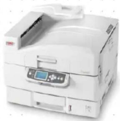
C9800hdn/C9800hdtn/C9800 GA
natural_image
White electronic device with control panel and display screen (no visible text or symbols)PREFACE
Every effort has been made to ensure that the information in this document is complete, accurate, and up-to-date. OKI assumes no responsibility for the results of errors beyond its control. OKI also cannot guarantee that changes in software and equipment made by other manufacturers and referred to in this guide will not affect the applicability of the information in it. Mention of software products manufactured by other companies does not necessarily constitute endorsement by OKI.
While all reasonable efforts have been made to make this document as accurate and helpful as possible, we make no warranty of any kind, expressed or implied, as to the accuracy or completeness of the information contained herein.
The most up-to-date drivers and manuals are available from the OKI web site:
http://www.okiprintingsolutions.com
Copyright © 2005 OKI Printing Solutions.
Oki and Microline are registered trademarks of Oki Electric Industry Company, Ltd.
ENERGY STAR is a trademark of the United States Environmental Protection Agency.
Microsoft, MS-DOS and Windows are registered trademarks of Microsoft Corporation.
Other product names and brand names are registered trademarks or trademarks of their proprietors.

As an ENERGY STAR Program Participant, the manufacturer has determined that this product meets the ENERGY STAR guidelines for energy efficiency.

This product complies with the requirements of the Council Directives 89/336/EEC (EMC), 73/23/EEC (LVD) and 1999/5/EC (R&TTE), as amended where applicable, on the approximation of the laws of the member states relating to Electromagnetic Compatibility, Low Voltage and Radio & Telecommunications Terminal Equipment.
This printer is equipped with the following embedded RFID read/write system:
Product name: Embedded RFID Read/Write System
Model number: RX4004A
The label on the RFID unit contains the following information:
Oki Data Corporation
Model number: RX4004A
Serial number:
Complies with IDA Standards DB100707

text_image
www.okiprintingsolutions.com OKINOTES, CAUTIONS AND WARNINGS!
NOTE
A note provides additional information to supplement the main text.
CAUTION!
A caution provides additional information which, if ignored, may result in equipment malfunction or damage.
WARNING!
A warning provides additional information which, if ignored, may result in a risk of personal injury.
SAFETY WARNINGS
This product has been carefully designed to give years of safe, reliable performance. As with all electrical equipment, however, there are a few basic precautions that should be taken to avoid injury or damage, therefore please be careful to read and understand the safety warnings on the following pages before operating the product.
WARNING!

Ensure all warning and instruction labels on this product are read, understood and followed in order to prevent any risk of injury.

Ensure this and all other documentation is both read carefully and retained for future reference.

This product may be heavy. Please check the weight of this product and take all necessary precautions to prevent any risk of personnel injury.

This product must be placed on a flat solid surface strong enough to support its weight to prevent any risk of injury.

Ensure that there is adequate ventilation all around this product to prevent overheating and any risk of fire.
WARNING!

Keep this product away from direct heat sources such as radiators and out of direct sunlight to prevent any risk of overheating.

The power supply required for this product is 220 - 240 VAC, 50/60 Hz. Refer to your product's rating label for full power rating details. Ensure that you have a suitable power supply before connecting the product. If in doubt contact your dealer or check with your local power provider.

Ensure both the product and mains power switches are in the OFF position before connecting the AC power cable.

This product has an earthed plug as a safety feature and will only connect to an earthed socket. Do not attempt to defeat the earthing or there is a risk of fire or shock.
WARNING!

If using an extension cable or power strip ensure that the total current rating (amperes) of all connected equipment is less than the maximum rating of the extension cable, power strip or wall outlet. Otherwise fire or shock may occur.
If this product is already supplied with a fitted power strip then NO additional power strip or extension cable should be used to connect to the mains wall outlet.

Ensure the power cable is routed so as not to be damaged or cause a trip hazard. If the cable becomes frayed or damaged, replace it immediately to prevent any risk of shock.

Do not twist, constrict or knot the power cable as this can cause overheating which may lead to fire or electric shock.

Ensure the power socket to which this product is connected is easily accessible at all times.

Do not connect or disconnect the power plug with a wet hand as this may cause electric shock.
WARNING!

Always hold the power plug to connect/disconnect the power cable to/from the mains socket. Unplugging by pulling on the cable can cause fraying and may lead to fire or electric shock.

Use only the power cable and power strip supplied. Using a power cable or power strip not intended for this product may lead to fire or electric shock.

To avoid risk of fire and electric shock, do not use the power cable or power strip supplied with this product for any other electrical equipment.

If you do not connect the power cord or any other cables only as directed in the User's Guide, this may result in a fire.

Ensure loose clothing and hair are kept clear of moving parts when this product is in operation to prevent possible risk of injury.

It is recommended that this product is switched off prior to opening any covers.

When this product's cover is open, do not touch the fuser unit or print head as you may receive burns. Allow them to cool before touching.
WARNING!

If this product's casing gets extremely hot or smoke, unusual smells or abnormal noises are emitted from this product, there is a risk of fire. Unplug the mains connector and contact your dealer.

If this product has been knocked over or damaged, there is a risk of electric shock, fire and/or injury. Unplug the mains connector and contact your dealer.

If any liquid (for example water) is allowed to enter this product, there is a risk of fire. Unplug the mains connector and contact your dealer.

Do not place containers containing liquid on this product as electric shock, fire and/or injuries may occur.

If any foreign objects (for example clips) are allowed to enter this product, there is a risk of electric shock, fire and/or injury. Unplug the mains connector before removing the object.

Do not introduce foreign objects into the ventilation holes or operate this product with covers open or removed as electric shock, fire and/or injuries may occur.
WARNING!

Do not use an extremely flammable spray near this product as the product contains high temperature parts that may cause a fire.

Switch this product off before cleaning to prevent any risk of injury. Clean using a damp cloth. Do not use liquid or aerosol cleaners.

Do not carry out any operations on this product that are not specified in the User's Guide. This may result in electric shock, fire and/or injury.

Do not touch the battery if one is fitted to the product. There is a risk of explosion if the battery is replaced by an incorrect type. The product battery should not require replacement during the life of the printer.

After installing additional memory, hard disk drive or any other internally fitted option, any covers removed or doors opened must be closed or replaced and secured to prevent any risk of fire or electric shock.
WARNING!

If items such as scanners or finishers are fitted, please exercise care when moving these items so as to avoid risk of entrapment or personnel injury.

If this product is installed on a cabinet or high capacity feeder, ensure wheel locks are applied once it is placed in final position for use, to prevent risk of movement or injury.

Take care with toner powder. If swallowed, induce vomiting and seek medical attention. Never attempt to induce vomiting if person is unconscious.

Take care with toner powder. If inhaled, move the person to an open area for fresh air. Seek medical attention.

Take care with toner powder. If it gets into the eyes, flush with large amounts of water for at least 15 minutes keeping eyelids open. Seek medical attention.

Take care with toner powder. Spillages should be treated with cold water and soap to help reduce risk of staining skin or clothing.
WARNING!

Do not throw toner cartridges or image drum cartridges into a fire as you may receive burns from a dust explosion.

This product is designed to operate within the following environmental operating conditions: Temp: 10 to 32°C Humidity: 20 to 80% RH

The acoustic noise level of this product is 70 dB(A) or less according to EN ISO 7779.
Imported into the EU by: OKI Europe Ltd (trading as OKI Printing Solutions) Central House, Balfour Road, Hounslow, Middlesex, TW3 1HY United Kingdom.
For all sales, support and general enquiries contact your local distributor.
CONTENTS
Preface 2
Notes, cautions and warnings! 4
Safety warnings 5
Introduction 16
Features 17
About this guide. 19
Online usage 20
Printing pages 21
Printer and paper overview 22
Opening and closing the top cover 22
Identifying major components 24
Software supplied. 29
Paper recommendations 30
Paper input and output information 31
Trays and stackers 32
Trays 1 to 5 32
MP tray.... 32
Face-down stacker 33
Face-up stacker 33
Duplex unit 33
Tray and stacker examples 34
Loading Trays 1 to 5 34
Using the MP Tray 36
Using the stackers 39
Control panel 41
Controls and indicators 41
LCD panel modes 43
Status information 43
Menu (Functions) information 43
Configuration information 44
Help mode 44
LCD panel messages. 44
Using the menus 45
Getting started 46
Printer location 46
Turning Off/On. 47
Turning Off 47
Turning On 48
Checking current settings 49
Interfaces and connection 49
Connecting the parallel interface ..... 50
Connecting the USB interface 51
Connecting the network interface ..... 51
Using the Drivers CD 52
Operation 53
Using the printer 53
Consumables and maintenance .... 54
Checking consumable/maintenance item usage 54
Replacement indications 54
Consumable item order information 55
Maintenance item order details 55
Replacing consumables/maintenance items ..... 56
Cleaning the LED heads 56
Cleaning the paper feed rollers 58
Cleaning the printer casing 62
Emptying the optional punch chip box 63
Optional accessories....66
Accessory order information 67
Installing accessories 68
Troubleshooting 69
General. 69
Paper jams 69
Paper jams - printer. 69
Open cover, paper jam, tttttt side cover ..... 69
Open cover, paper jam, side cover. 71
Open cover, paper jam, top cover ..... 73
Paper jams - duplex unit 79
Check duplex unit, paper jam 79
Paper jams - Finisher (optional accessory) ..... 84
Check Finisher, paper jam/paper remains ..... 84
591, 592, 593, 599/ 643, 645 (paper jam around Finisher) 84
594, 597, 598/ 644, 646 (paper jam in Finisher) 86
590 (paper jam in Finisher/Punch unit) ..... 90
Check Inverter, paper jam 92
Avoiding paper jams. 97
Dealing with unsatisfactory printing ..... 98
Staple jams - Finisher (optional accessory) .....100
Check Finisher, Staple Jam .....100
Specifications 105
Appendix A - LCD Messages. 107
Appendix B - Menu system 109
Configuration.....110
Print Page Count .....110
Finisher Count .....110
Supplies Life .....111
Network 111
Paper Size in Tray .....112
System.....112
Configuration example – monochrome pages printed .....113
Print Pages 114
Print Information example – demonstration page 115
Print Secure Job. 115
Menus. 116
Tray Configuration .....116
System Adjust. 120
Menus example 1 - Tray 1 transparencies ....124
Menus example 2 - MP Tray paper size .....125
Index 126
OKI contact details 128
INTRODUCTION
Congratulations on buying a colour printer from OKI Printing Solutions. Your new printer is designed with advanced features to give you clear, vibrant colour prints and crisp black and white pages at high speed on a range of print media for the office.
In addition, the EFI Fiery print control and job management functionality allows you to:
manage or preview jobs in the print queue via command workstation
balance the workflow of networked devices
manage colour profiles
save templates on the hard disk for faster processing and printing of jobs
The C9800 Series comprises:
C9800hdn, C9800hdtn (which can be upgraded to C9800 MFP but not to C9800 GA)
C9800 MFP
C9800 GA
C9800 GA MFP
where h denotes hard disk installed, d denotes duplex unit installed, n denotes networking capability, t denotes high capacity feeder installed, MFP denotes multi-function peripheral installed and GA denotes Graphic Arts capability.
This user's guide describes the C9800hdn, C9800hdtn and C9800 GA models. A separate user's guide describes the C9800 MFP and C9800 GA MFP models.
FEATURES
The following features are standard on all models:
Up to 36 pages per minute in full colour for fast printing of high impact colour presentations and other documents
Up to 40 pages per minute in black and white for fast and efficient printing of all general purpose documents not requiring colour
ProQ4800 Multilevel technology produces subtler tones and smoother gradations of colour to lend photographic quality to your documents
1200 x 1200 dpi (dots per inch) print resolution for high quality image production showing the finest detail
Single Pass Colour Digital LED technology for high speed processing of your printed pages
10Base-T and 100Base-TX network connection lets you share this valuable resource among users on your office network
Automatic two-sided (duplex) printing for economical use of paper and compact printing of larger documents
Hard Disk Drive enables spooled and verified printing
USB 2.0 and parallel (IEEE-1284) interfaces
PCL, PS
EFI Fiery controller and software
Graphics Arts capability with full suite of EFI utilities including Spot-On and Hot Folder support (C9800 GA only)
"Ask Oki" – a brand new, user-friendly function that gives a direct link from your printer driver screen (but not illustrated in this guide) to a dedicated web site specific to the exact model you are using. This is where you will find all the advice, assistance and support you could need to help you get the best possible results from your Oki printer.
Additionally, the following optional features are available:
Additional paper trays for loading a further 530 sheets at a time to reduce operator intervention, or different paper stocks for letterhead stationery, alternative paper sizes or other print media:
2nd/3rd Tray (530 sheets each)
High Capacity Feeder (HCF) (1590 sheets)
NOTE
- Tray configurations are: Tray 1 only, Tray 1 + 2nd Tray, Tray 1 + 2nd Tray + 3rd Tray, Tray 1 + HCF, Tray 1 + 2nd Tray + HCF
- The C9800hdtn already has a High Capacity Feeder installed and so can only accommodate one additional tray (to give the maximum total of five).
Memory Expansion DIMM
Finisher for stapling or saddle stitching printer output
Punch unit (to extend Finisher functionality)
Printer Cabinet
EFI Color Profiler Kit
MFP Upgrade Kit (C9800hdn only)
ABOUT THIS GUIDE
NOTE
Images used in this manual may include optional features that your printer does not have installed. Also, they may omit features not essential to the description of a particular function.
This manual is your user's guide (check the web site, www.okiprintingsolutions.com, for the most up-to-date version) for your printer and forms part of the overall user support listed below:
Set-up guide: to describe how to unpack, connect and turn on your printer
This is a paper document that is packaged with the printer.Quick start guide: to describe how to proceed after following the set-up guide.
This is a paper document that is packaged with the printer.
Software summary guide: to provide an overview of drivers and utilities provided.
This is an electronic document stored on CD3.
This User's Guide: to help you to become familiar with your printer and make the best use of its many features. Also included are guidelines for troubleshooting and maintenance to ensure that it performs at its best. Additionally, information is provided for adding optional accessories as your printing needs evolve.
This is an electronic document stored on CD3.
Printing Guide for Windows users and Mac users: to help you operate your printer effectively and efficiently This is an electronic document stored on CD3.
Configuration Guide: to provide machine configuration and network configuration information This is an electronic document stored on CD3.
EFI Fiery documentation suite
These are electronic documents stored on CD2.
Installation Guides: accompany consumable items and optional accessories to describe how to install them
These are paper documents that are packaged with the consumables and optional accessories.
Online Help: online information accessible from the printer driver and utility software
ONLINE USAGE
This guide is intended to be read on screen using an Adobe Acrobat Reader. Use the navigation and viewing tools provided in Acrobat.
You can access specific information in two ways:
In the list of bookmarks down the left hand side of your screen, click on the topic of interest to jump to the required topic. (If the bookmarks are not available, use the "Contents" on page 13.)
In the list of bookmarks, click on Index to jump to the Index. (If the bookmarks are not available, use the "Contents" on page 13.) Find the term of interest in the alphabetically arranged index and click on the associated page number to jump to the page containing the term.
PRINTING PAGES
The whole manual, individual pages, or sections may be printed. The procedure is:
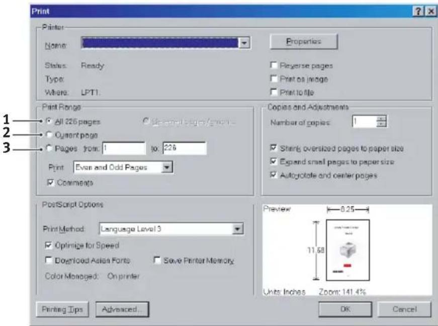
- From the toolbar, select [File], then [Print] (or press the Ctrl + P keys).
- Choose which pages you wish to print:
(a) [All pages], (1), for the entire manual.
(b) [Current page], (2), for the page at which you are looking.
text_image
Print Printer Name: Properties Status: Ready Reverse pages Type: Print as image Where: LPT1 Print Range All 226 pages Current page Pages from: 1 to: 226 Print: Even and Odd Pages Comments Copies and Adjustments Number of copies: Shining oversized pages to paper size Expand small pages to paper size Autoglcote and center pages PostScript Options Print Method: Language Level 3 Optimize for Speed Downloaded Asien Fonts Save Printer Memory Color Managed: On printer Preview 8.25 Units Inches Zoom: 141.4% Printing Tips Advanced... OK Cancel(c) [Pages from] and [to], (3), for the range of pages you specify by entering their page numbers.
text_image
Home The line art graphics is in this PostScript. So if you plan to install choose the PostScript within art graphics will install. If your applications want much that neither do your needs, you could choose to install back. It plans to see most of the lines to be your Window application allows you to choose a different print dialogues, so you can print using the other Prints installed (A)- Click on [OK].
PRINTER AND PAPER OVERVIEW
OPENING AND CLOSING THE TOP COVER
CAUTION!
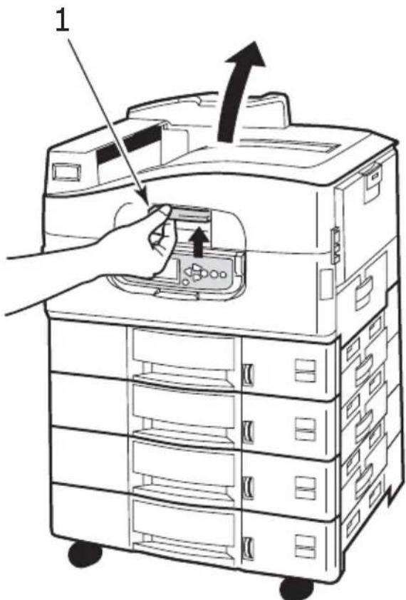
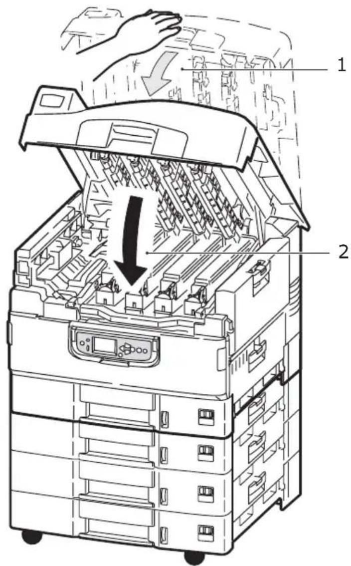
To gain access to the inside of the printer, ensure that the top cover is fully opened.
To open the top cover, squeeze the top cover handle (1) to release the catch and raise the cover.
text_image
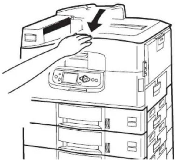
1To close the top cover, push gently (1) until the cover stops midway and then push harder (2) to close the cover completely. Ensure that the cover is securely closed.
text_image
Technical diagram of a multi-level electronic device with labeled parts and directional arrows indicating internal components.IDENTIFYING MAJOR COMPONENTS
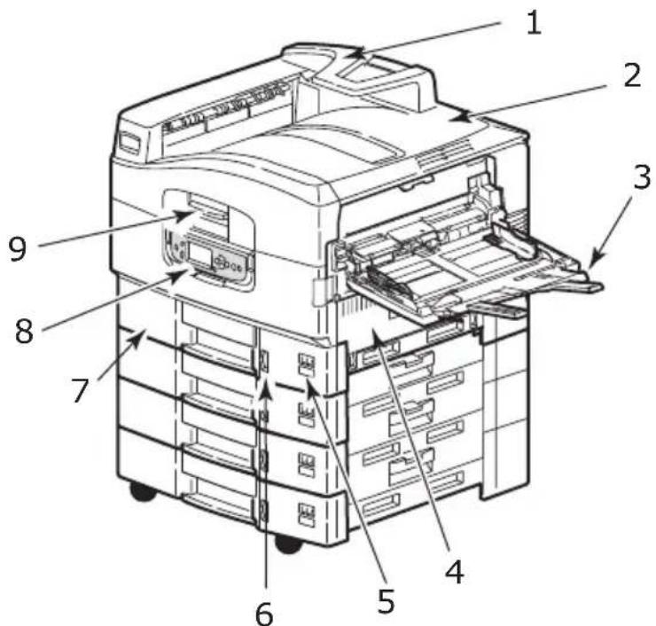
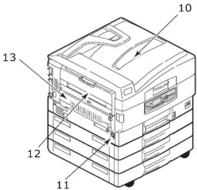
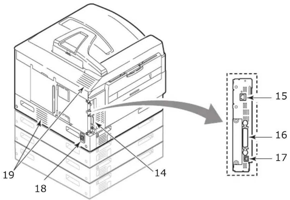
The major components of your printer are identified in the representations below.
- Paper holding arm
- Top cover (face-down stacker)
- MP Tray (multi-purpose tray)
- Tray 1 side cover
- Paper size label
- Paper volume indicator
- Tray 1 (paper tray)
- Control panel
- Top cover handle
text_image
Technical diagram of a multi-chamber printer with numbered parts labeled for identification.- Face-down stacker
- Power (on/off) switch
- Face-up stacker
- Duplex unit
text_image
Technical diagram of a multi-tiered printer or rack with numbered parts labeled 10, 11, 12, and 13.- Interface unit
- Network interface connector
- Parallel interface connector
- USB interface connector
- Power connector
- Ventilation holes
text_image
19 18 14 15 16 17- Image drum cartridge and toner cartridge (Cyan)
- Image drum cartridge and toner cartridge (Magenta)
- Image drum cartridge and toner cartridge (Yellow)
- Image drum cartridge and toner cartridge (Black)
- Toner cartridge
- Image drum cartridge
- Fuser unit
- LED heads
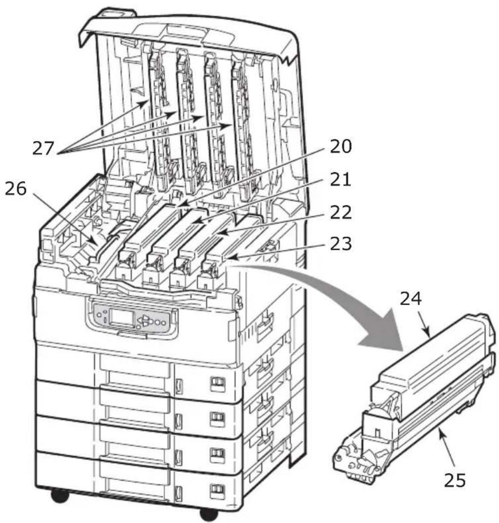
text_image
27 26 20 21 22 23 24 25- Belt unit
- Drum basket handle
- Drum basket
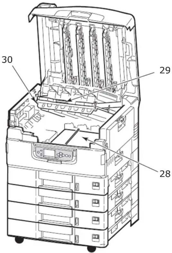
text_image
30 29 28- High capacity Feeder (HCF) 3 trays (standard on C9800hdtn)
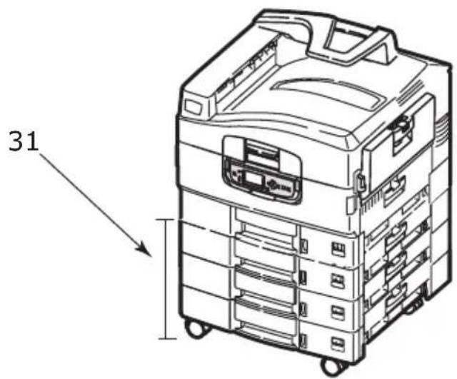
text_image
31SOFTWARE SUPPLIED
CDs:
CD1 - Drivers and Utilities
Contains driver and application software for use by a general user.
CD2 - Network, EFI and Administrator Utilities
Contains software for use by system administrators.
CD3 - User's Guides
Contains documentation in electronic form (for example, the User's Guide and Printing Guide) to describe how to use the printer for day-to-day printing tasks.
PAPER RECOMMENDATIONS
Your printer will handle a variety of print media, including a range of paper weights and sizes, transparencies and envelopes. This section provides general advice on choice of media, and explains how to use each type.
The best performance will be obtained when using standard weight 75 - 90g/m ^2 paper designed for use in copiers and laser printers. Suitable types are:
Arjo Wiggins Colour Solutions 90g/m²
Colour Copy by Neusiedler
Use of heavily embossed or very rough textured paper is not recommended.
Pre-printed stationery can be used, but the ink must not offset when exposed to the high fuser temperatures used in the printing process.
Envelopes should be free from twist, curl or other deformations.
They should also be of the rectangular flap type, with glue that remains intact when subjected to hot roll pressure fusing used in this type of printer. Window envelopes are not suitable.
Transparencies should be of the type designed for use in copiers and laser printers. In particular, avoid office transparencies designed for use by hand with marker pens. These will melt in the fuser and cause damage.
Labels should also be of the type recommended for use in copiers and laser printers, in which the base carrier page is entirely covered by labels. Other types of label stock may damage the printer due to the labels peeling off during the printing process. Suitable types are:
Avery White Laser Label types 7162, 7664, 7666 (A4), or 5161 (Letter)
Kokuyo A693X series (A4) or A650 (B5)
PAPER INPUT AND OUTPUT INFORMATION
The following table relates paper parameters to input trays (Tray 1 to Tray 5 (numbering from the top) and MP Tray) and to output areas (Face-down stacker and Face-up stacker).
| TYPE SIZE WEIGHT INPUT/ | OUTPUT | ||
| Plain paper A3, A3 | Nobi, A3 Wide,A4, A5, A6, B4, B5,Letter, Legal 13,Legal 13.5, Legal 14,Executive, Tabloid,Tabloid Extra | 64 - 216g/m^2 Any TrayAny Stacker | |
| CustomW: 100 – 328mML: 148 – 457.2mm | 64 - 216g/m^2 Any TrayFace-up Stacker | ||
| CustomW: 79.2 – 328mML: 90 – 457.2mm | 64 - 268g/m^2 MP TrayFace-up Stacker | ||
| BannerW: A4 widthL: 457.2 –1200mm | 128g/m^2 recommended | MP TrayFace-up Stacker | |
| Index card:76.2 x 127mm | 64 - 268g/m^2 MP TrayFace-up Stacker | ||
| Postcard – – Tray | 1 or MP Tray | Face-up Stacker | |
| Envelope 120 x | 235mm90 x 205mm235 x 120mm235 x 105mm240 x 332mm216 x 277mm119 x 197mm210 x 297mm | 85g/m^2 MP Tray | Face-up Stacker |
| 324 x 229mm229 x 162mm220 x 110mm225.4 x 98.4mm241.3 x 104.8mm190.5 x 98.4mm | Based on 90g/m^2 paper | ||
| Labels A4, Letter, | B5 0.1 – 0.2mm MP | Tray | Face-up Stacker |
| Transparencies Glossy paper | A4, Letter 0.1 – 0.11mm | Tray 1 or MP Tray | Face-up Stacker |
TRAYS AND STACKERS
TRAYS 1 TO 5
Tray 1 is the standard paper input tray and can hold up to 530 sheets of paper. Additional trays, to give a total of five, can be added as an option to give a total tray capacity of 2650 sheets of paper.
If you have identical paper stock loaded in another tray (for example Tray 2 or the MP Tray), you can have the printer automatically switch to that other tray when the current tray runs out of paper. This function can be enabled by driver settings when printing from a Windows application or by a menu setting when printing from other applications.
MP TRAY
The multi-purpose tray is used for media sizes additional to those of the standard trays, heavier media weights and special media.
The multi-purpose tray can handle the same sizes as the standard trays but in weights up to 268g/m^2 . For very heavy paper stock use the face-up paper stacker. This ensures that the paper path through the printer is almost straight.
The multi-purpose tray can feed paper widths as small as 76.2mm and lengths up to 1200mm. For banner printing, recommended sizes are A4 wide, 900mm and 1200mm long and weight 128g/m². Since paper of width less than 100mm does not autofeed, you have to press the ONLINE button to cause it to feed.
Use the multi-purpose tray for printing on envelopes and transparencies. Up to 100 sheets of transparencies or 25 envelopes can be loaded at one time, subject to a maximum stacking depth of 25mm.
Paper or transparencies should be loaded print side up and top edge into the printer. Do not use the duplex (two-sided printing) function for transparencies.
FACE-DOWN STACKER
The face-down stacker on the top of the printer can hold up to 500 sheets of 80g / m^2 standard paper, and can handle paper stocks from 64 - 216g/m². Pages printed in reading order (page 1 first) will be sorted in reading order (last page on top, facing down).
FACE-UP STACKER
The face-up stacker should be opened and the tray extension pulled out when required for use. (With the face-up stacker either open or closed, the driver setting of Face Down will successfully direct prints to the Face-Down stacker.)
The face-up stacker can hold up to 250 sheets of 80g/m^2 standard paper and can handle stocks up to 268g/m^2 .
Always use this stacker and the multi-purpose feeder for paper stocks heavier than 216g/m^2 .
DUPLEX UNIT
This unit provides automatic two-sided printing on plain paper fed from Trays 1 – 5 or the MP Tray. Applicable paper sizes are A6, A5, B5, B5LEF, Executive, A4, A4LEF, Letter, LetterLEF, Legal 13 in, Legal 13.5 in, Legal 14 in, B4, Tabloid, Tabloid Extra, A3, A3 Wide, A3 Nobi, Custom size (100 – 328mm wide, 148 – 457.2mm long), using paper stocks in the range 64 – 120g/m².
TRAY AND STACKER EXAMPLES
LOADING TRAYS 1 TO 5
Tray 1 is used in the following example.
- Pull out the tray.
- Press the paper rear stopper tab (1) and adjust the tab to the required paper size.
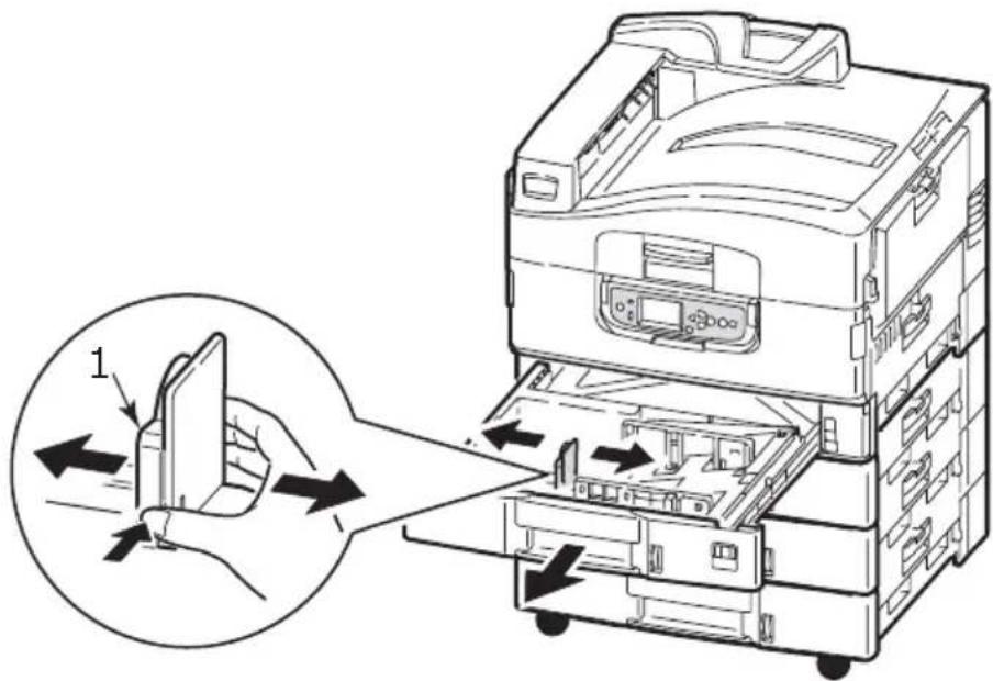
text_image
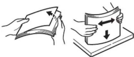
Diagram of a printer's internal structure showing hand placement and assembly, with labeled component '1'- Fan the paper to be loaded then tap the edges of the stack on a flat surface to make it flush.
natural_image
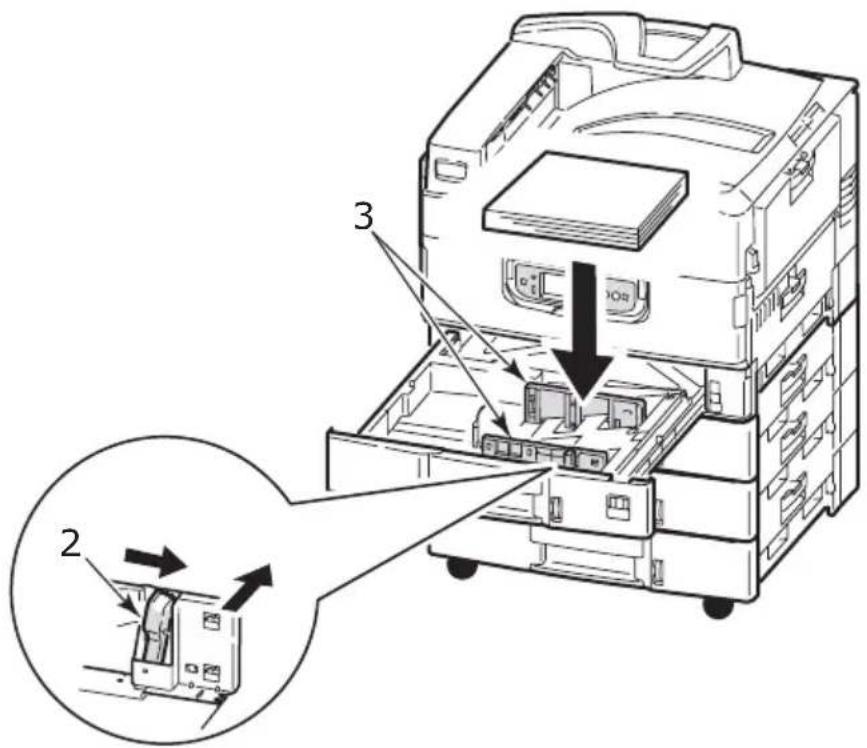
Illustration showing two steps of folding a document: one being folded, the other holding a card with arrows indicating movement (no text or symbols present)- Load the paper (face down and top edge towards the right for headed paper), press the tab (2) on the paper guide and adjust the guides (3) for a snug fit to the paper.
To avoid paper jams:
Do not leave space between the paper and the guides and rear stopper.
Do not overfill the paper tray. Capacity depends on the paper type.
Do not load damaged paper.
Do not load paper of different sizes or types at the same time.
text_image
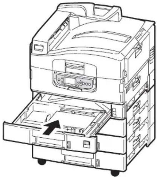
Technical diagram of a printer internal structure with labeled components and directional arrows indicating assembly or movement.- Gently push the tray back into the printer.
natural_image
Line drawing of a multi-tiered electronic device with internal compartments and an arrow indicating a component (no text or symbols present)USING THE MP TRAY
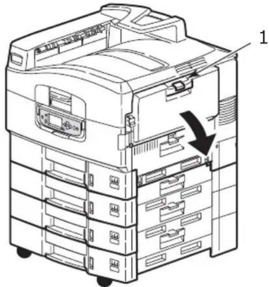
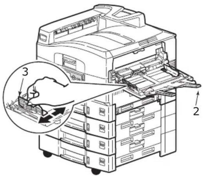
- Squeeze the handle (1) and open the multi-purpose tray.
text_image
Technical diagram of a multi-chamber printer with labeled parts and an arrow indicating a component or operation.- Fold out the paper support section and swivel out the extension supports (2).
text_image
Technical diagram of a printer with labeled parts and a magnified inset showing hand positioning and assembly steps-
Adjust the paper guides (3) to the size of the paper being used.
-
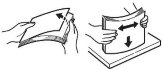
Fan the paper to be loaded then tap the edges of the stack on a flat surface to make it flush.
natural_image
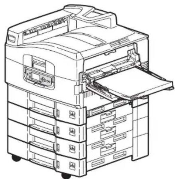
Illustration showing two hand-drawn steps: folding a sheet and holding a card, with arrows indicating direction (no text or symbols)5. Load the paper.
For single-sided printing on headed paper, load the paper into the multi-purpose tray with pre-printed side up and top edge into the printer.
For two-sided (duplex) printing on headed paper, load the paper with pre-printed side down and top edge away from the printer.
Envelopes should be loaded face-up with long edge into the printer. Do not select duplex printing on envelopes.
Do not leave space between the paper and the guides.
Do not exceed the paper capacity of approximately 230 sheets, 100 transparencies or 25 envelopes. Maximum stacking depth is 25mm.
natural_image
Line drawing of an open file organizer with multiple rack-mounted folders and a paper feeding into one sheet (no text or symbols visible)USING THE STACKERS
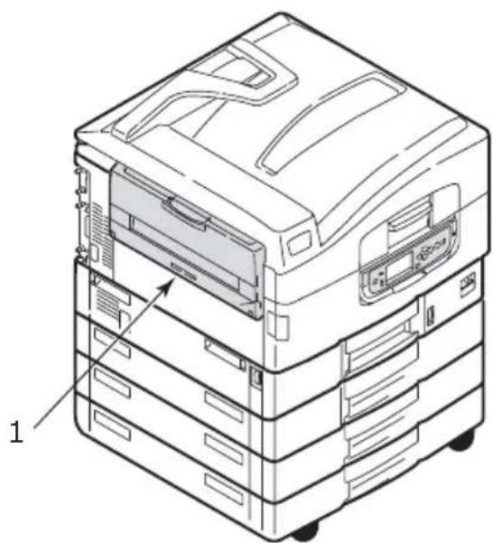
Face-down stacker
When the face-up stacker (1) on the left side of the printer is closed (its normal position), paper is ejected to the face-down stacker on the top of the printer.
natural_image
Technical line drawing of a multi-tiered electronic device with labeled components (no text or symbols present)Face-up stacker
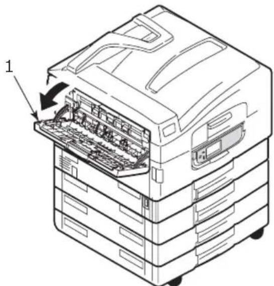
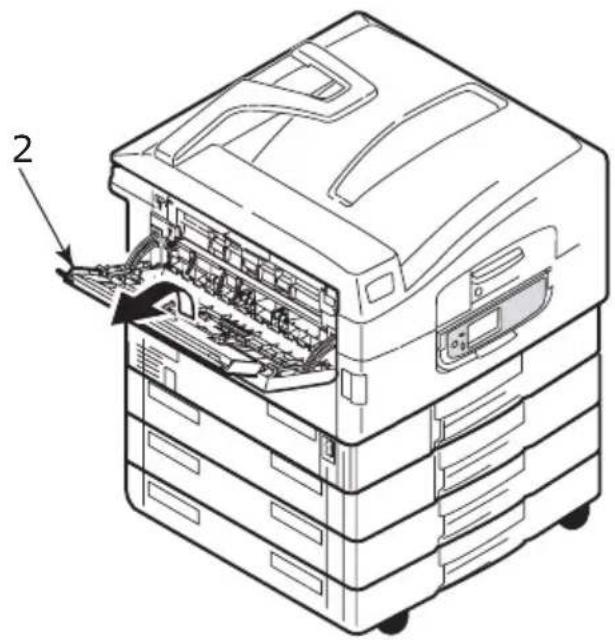
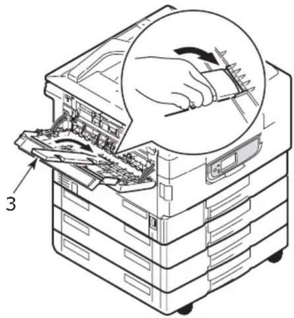
The face-up exit path is used for heavy paper (cardstock etc.), envelopes, transparencies, and labels.
- Open the stacker (1).
text_image
1- Flip out the paper support (2).
text_image
2- Swivel out the paper support extension (3).
text_image
3CONTROL PANEL
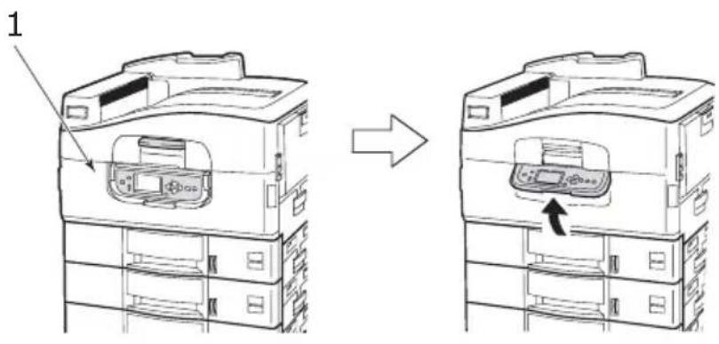
The control panel can be swivelled to 90^ (maximum) upwards from its base position (1) as required for ease of use.
text_image
1CONTROLS AND INDICATORS
The parts of the control panel are identified and briefly explained below:
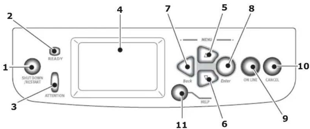
text_image
2 READY 1 SHUT DOWN /RESTART ATTENTION 3 4 7 MENU 5 8 Back Enter ON LINE CANCEL 10 HELP 6 9 111. Shutdown/Restart button
Press and hold down for a soft shutdown. You can then press this button again for a restart or use the Power switch to turn off the printer completely.
2. Ready indicator
On: indicates ready to print
Flashing: indicates processing print data
Off: indicates unable to receive data (offline)
3. Attention indicator
Off: indicates normal operation
Flashing: indicates error(s) present but printing can continue
On: indicates error(s) present and printing cannot continue
4. LCD panel
Displays status and setup information for the printer and user help information in your chosen language
5. Up-arrow button
Enters menu mode and enables upward movement through the displayed list of menu items
6. Down-arrow button
Enters menu mode and enables downward movement through the displayed list of menu items
7. Back button
Returns to the previous higher level menu item
8. Enter button
Enters menu mode and selects the menu item highlighted in the LCD panel
9. Online button
Switches between online (printer ready to receive data) and offline (printer not ready to receive data)
10. Cancel button
Cancels current print job
11. Help button
Provides additional textual or image data to supplement what is displayed on the LCD panel
LCD PANEL MODES
The LCD panel can display the following:
Status information
Menu (functions) information
Configuration information
Help information
STATUS INFORMATION
Status information is associated with three printer states:
In the Information state, such as idling or printing, the printer is able to process print jobs.
In the Warning state, the printer has encountered some minor problem but is still able to process print jobs.
In the Error state, the printer has encountered a problem and cannot continue printing until the user has intervened and removed the cause of the trouble.
The top two lines of the display panel show the printer status. The bottom of the display panel normally shows a bar chart of the toner usage.
MENU (FUNCTIONS) INFORMATION
There are three types of menu (functions) information:
User menus: activated by pressing the Enter button, Up-arrow or Down-arrow button on the control panel. These menus are available to the general user to make various settings that are used in the running of the printer.
Administrator menu: activated by pressing the Enter button for more than 2 seconds while turning on the printer power supply (including Restart). Available to administrator level users. Restricts the changes that general users can make via the user menus.
System maintenance menu: activated by pressing the Up-arrow and Down-arrow buttons together for more than 2 seconds while turning on the printer power supply
(including Restart). Available to specialist staff to allow printer configurations and special functions to be set.
CONFIGURATION INFORMATION
Configuration information displays printer configuration information such as internal firmware versions.
Menu options at each level can be scrolled through by moving the highlight with the Up-arrow/Down-arrow buttons and a highlighted option at that level can be selected by pressing the Enter button. When the lowest level menu has been selected, you can change the setting for that menu by selecting the required highlighted value from a list or by entering a numeric value. In other cases, you can display or print configuration information.
HELP MODE
When an error has occurred, press the Help button. Information displays that will help you correct the error.
LCD PANEL MESSAGES
The LCD panel messages, supplemented by the Help messages where appropriate, are intended to be self-explanatory. More information on typical messages is provided in "Appendix A – LCD Messages" on page 107.
USING THE MENUS
NOTE
Menu details are given in "Appendix B - Menu system" on page 109 for reference.
The Enter, Up-arrow, Down-arrow and Back buttons are used to move through the printer menus. You can adjust settings (e.g. set the paper size for Tray 1) or view information (e.g. how much is left of a selected consumable).
Many of these menu settings can be, and often are, overridden by settings in the Windows printer drivers. However, several of the driver settings can be left at "Printer Setting," which will then default to the settings entered in these printer menus.
The steps involved in using the menus are typically as follows:
- Ensure that the LCD panel indicates that the printer is ready to print.
- Enter User menu mode by pressing either the Enter button or the Up-arrow or Down-arrow button and press the latter two repeatedly until the desired menu is highlighted in the displayed list.
- Press the Enter button to select this menu.
- Press the Up-arrow or Down-arrow buttons repeatedly until the desired Item is highlighted.
- Press the Enter button to select this Item.
- Press the Up-arrow or Down-arrow buttons repeatedly until the desired Value is highlighted.
- Press the Enter button to select this Value. (If you are setting a parameter, ensure that an asterisk (*) appears beside the selected parameter Value.)
- Press the Online button to exit menu mode and return to the ready to print status.
Refer to the section entitled "Getting started" on page 46 and "Appendix B – Menu system" on page 109 for examples of using the menus.
GETTING STARTED
This section provides information to help you get started with using your printer.
PRINTER LOCATION
Check that you have sufficient space for access:
around your printer:
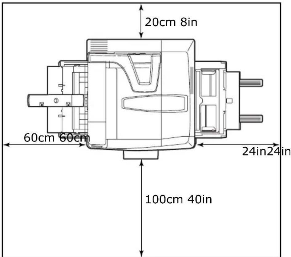
text_image
20cm 8in 60cm 60cm 100cm 40in 24in24inabove your printer:
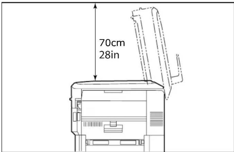
text_image
70cm 28inTURNING OFF/ON
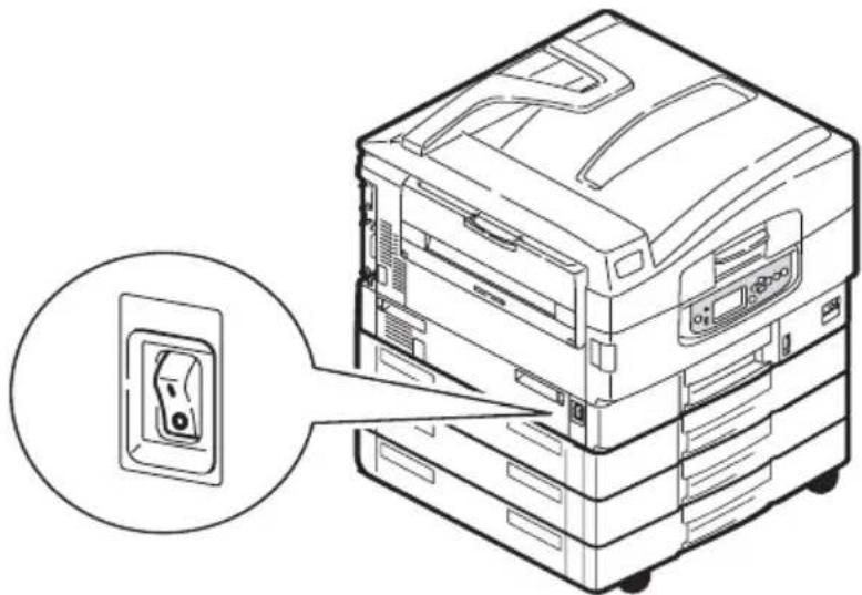
TURNING OFF
- Press and hold down the Shutdown/Restart button (1) on the control panel to start the shutdown process.
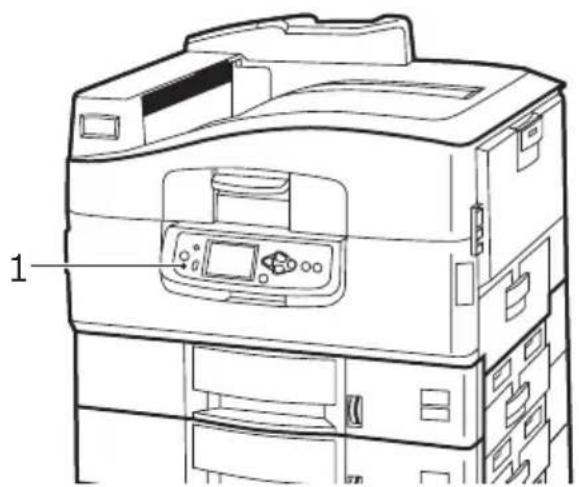
text_image
1- When the LCD display shows that you can either turn off or restart the printer, set the printer Power switch to Off. Please wait as this may take a short time.
natural_image
Line drawing of a server rack with an open socket, showing internal components and a magnified inset (no text or symbols)TURNING ON
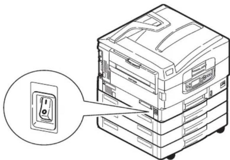
NOTE If you have used the Shutdown/Restart button to reduce the printer to a state where the LCD panel indicates it can be turned off or restarted, you can turn it on again by pressing the Shutdown/Restart button.
- To start the printer after it has been turned off by using the Power switch, set the Power switch to On. Please wait as this may take a short time.
natural_image
Line drawing of a multi-tiered electronic device with an open switch symbol, no text or labels presentCHECKING CURRENT SETTINGS
Carry out the following steps to generate a Configuration report (Menu Map) to confirm that your printer is correctly configured.
- Ensure that there is A4 paper in Tray 1 (to be used in this operation).
- Ensure that the LCD panel indicates that the printer is ready to print.
- Press the Up-arrow or Down-arrow buttons repeatedly until Print Pages is highlighted.
- Press the Enter button to select Print Pages.
- Press the Up-arrow or Down-arrow buttons repeatedly until Configuration is highlighted.
- Press the Enter button to select Configuration.
- Press the Enter button to execute the command and a Configuration document is printed.
- After printing the configuration document, the printer returns to the ready to print status.
- You can use this document to check your printer configuration. System values and installed accessories are listed at the top of the first page while status values and settings follow.
INTERFACES AND CONNECTION
Your printer is equipped with a selection of data interfaces:
Parallel – For direct connection to a PC. This port requires a bi-directional (IEEE 1284 compliant) parallel cable.
USB – For connection to a PC running Windows 98 or above (not Windows 95 upgraded to Windows 98) or Macintosh. This port requires a cable conforming to USB version 2.0 or above.
The printer may not work if a USB-compatible device is connected concurrently with other USB-compatible machines.
When connecting multiple printers of the same type, they appear as * . These numbers depend on the order of connecting or turning on each printer.
Ethernet – For network cable connection.
NOTE
Interface cables are not supplied with your printer.
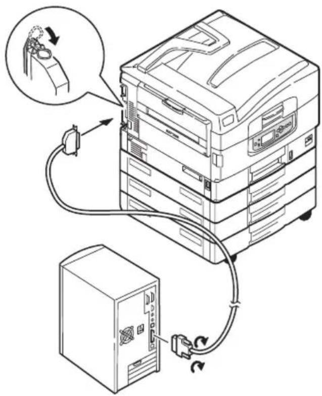
CONNECTING THE PARALLEL INTERFACE
-
Turn off the printer and the computer.
-
Connect a parallel cable between the printer and computer.
text_image
Diagram showing server rack connected to a computer tower via cable, with magnified inset illustrating the cable's adjustment.- Turn on the printer and then the computer.
CONNECTING THE USB INTERFACE
Do not connect the USB cable at this time. You will be instructed when to connect the USB cable when you run the Drivers CD, CD1.
If you are connecting your printer directly to a stand alone computer proceed to the section entitled "Using the Drivers CD" on page 52.
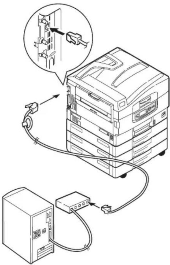
CONNECTING THE NETWORK INTERFACE
CAUTION!
Do not connect a USB cable into the network interface connector as this may lead to malfunction.
- Turn off the printer and the computer.
- Connect an Ethernet cable between the printer and an Ethernet hub.
text_image
Diagram illustrating server rack connection with labeled components and cable routing- Turn on the printer and then the computer.
If your printer is to be installed as a network printer, please refer to the relevant section in the Configuration Guide for further details on how to configure the network connection before installing the printer drivers.
NOTE
Administrator's authority is required when installing a network connection.
Insert the Drivers CD into your computer and follow the on-screen instructions. You are prompted to follow a set of basic steps to configure the display panel language, install drivers and other software and finally print a test page to check that your printer is operating correctly thus far.
OPERATION
USING THE PRINTER
For full details of how to use the printer and any optional accessories to print jobs efficiently and effectively, please refer to the Printing Guide.
This section explains how to replace consumable and maintenance items when due. As a guide, the life expectancy of these items is:
Toner — 15,000 A4 pages at 5% coverage.
The printer is shipped with sufficient toner for 7,500 pages in the print cartridges of which 1 – 2,000 pages of toner are used to charge the image drum.
Image drum — 30,000 A4 pages average life
Transfer belt — Approximately 100,000 A4 pages
Fuser — Approximately 100,000 A4 pages
At any time, you can check how much of each consumable/maintenance item is left by using the appropriate menus. For example, enter the menu system and follow the path:
Configuration>Supplies Life>Cyan Toner
The percentage of Cyan Toner remaining is displayed on the LCD panel and the printer then returns to the ready to print status.
REPLACEMENT INDICATIONS
The LCD panel provides messages to the effect that consumables/maintenance items are running low or nearing end of life followed some time later by a message that replacement is required. You should replace the item as soon as possible after this message is displayed to avoid the possibility of print quality being compromised.
The paper feed rollers and the multi-purpose (MP) tray feed rollers do not have any replacement warning messages. Recommended replacement: after approximately 120,000 A4 sheets.
CONSUMABLE ITEM ORDER INFORMATION
| ITEM LIFE ORDER NUMBER | ||
| Toner, Black 15,000 A4 pages @ 5% 42918916 | ||
| Toner, Cyan 15,000 A4 pages @ 5% 42918915 | ||
| Toner, Magenta 15,000 A4 pages @ 5% 42918914 | ||
| Toner, Yellow 15,000 A4 pages @ 5% 42918913 | ||
| Toner, rainbow p a c k(1 ea. CMYK toner) | 15,000 A4 pages @ 5% 43112702 | |
| Image drum, Black 30,000 A4 pages avg 42918108 | ||
| Image drum, Cyan 30,000 A4 pages avg 42918107 | ||
| Image drum, Magenta 30,000 A4 pages avg 42918106 | ||
| Image drum, Yellow | 30,000 A4 pages avg 42918105 | |
| Staples | 3 x 3000 staples | 42937603 |
MAINTENANCE ITEM ORDER DETAILS
| ITEM LIFE ORDER NUMBER | ||
| Fuser unit | 100,000 A4 pages | 42931703 |
| Belt unit | 100,000 A4 pages | 42931603 |
| Waste toner container | 30,000 A4 pages avg 42869403 | |
| Hopping roller set (Tray) | 120,000 A4 pages | 42931803 |
| Hopping roller set (MPT) | 120,000 A4 pages | 42939703 |
REPLACING CONSUMABLES/MAINTENANCE ITEMS
Each consumable item comes complete with its own installation details which give full instructions on replacement. You are advised to follow these instructions carefully.
CAUTION!
For the protection of your printer, and in order to ensure that you benefit from its full functionality, this model has been designed to operate only with genuine OKI Printing Solutions toner cartridges. These can be identified by the OKI Printing Solutions trademark. Any other toner cartridge may not operate at all, even if it is described as “compatible”, and if it does work, your printer’s performance and print quality may be degraded.
CLEANING THE LED HEADS
You are advised to clean the LED heads:
any time you replace a toner cartridge (a LED lens cleaner is enclosed with each replacement toner cartridge)
if printing is showing signs of faded images, white stripes or blurred letters
You can use a LED lens cleaner or dry, soft cloth for cleaning the LED heads.
- Open the top cover.
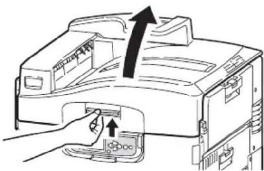
natural_image
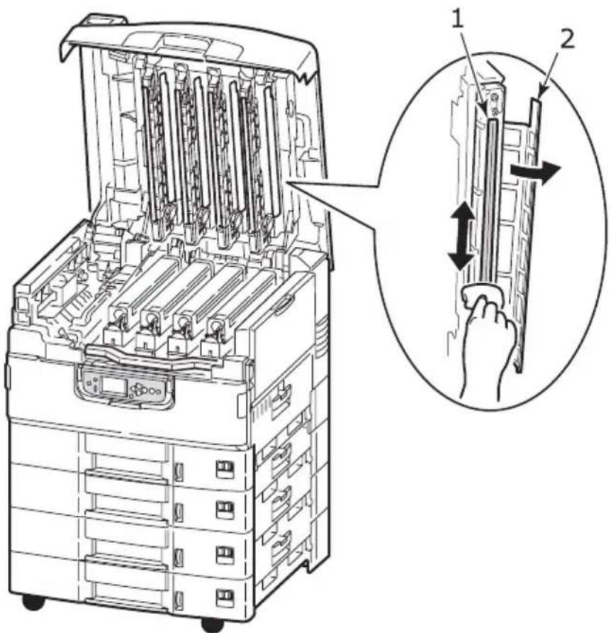
Diagram of a printer's internal structure with an arrow indicating upward motion (no text or symbols present)- With an LED lens cleaner or soft cloth, gently wipe each of the four heads (1). Move the cleaner as shown, using a clean section of the cleaner with each pass. Be careful not to damage the guards (2).
text_image
Technical diagram of a multi-compartment electronic device with labeled parts and an inset showing hand positioning and adjustment mechanism.- Close the top cover.
natural_image
Line drawing of a hand pressing down on an open printer stack (no text or symbols)Clean the paper feed rollers if paper jams frequently occur.
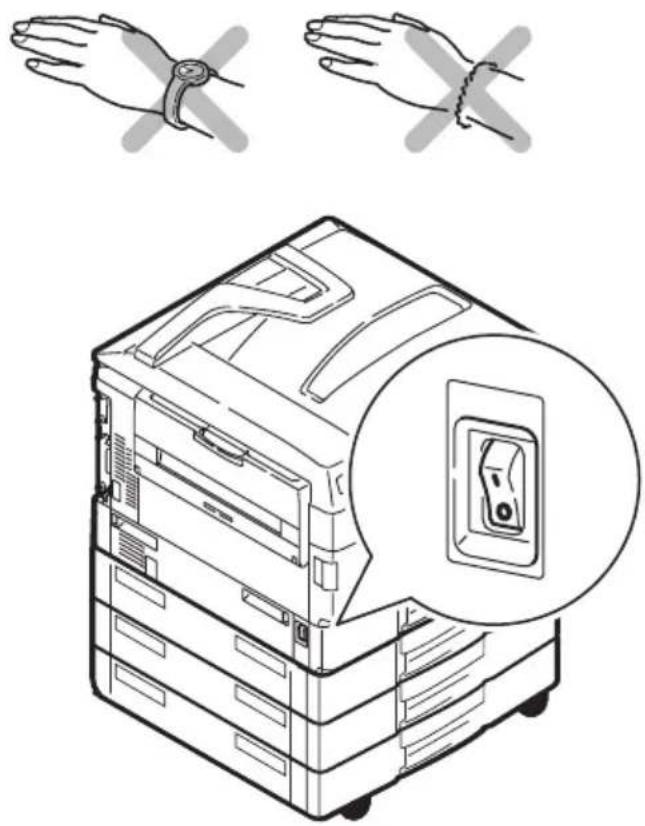
- Remove items like a wrist watch or bracelet then use the Shutdown/Restart button followed by the On/Off switch to turn the printer off.
natural_image
Illustration of a rack-mounted server unit with two hands clamped, showing a close-up of its internal socket (no text or symbols present)- Open Tray 1 side cover.
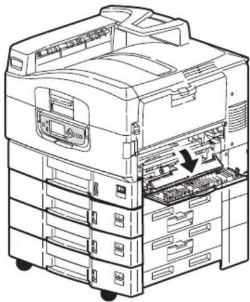
natural_image
Technical line drawing of an open industrial machine with internal components and a downward arrow indicating a component (no text or symbols present)- Remove Tray 1 completely from the printer.
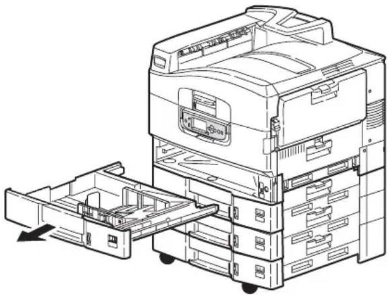
natural_image
Technical line drawing of a multi-chamber office machine with internal compartments and a loading mechanism (no text or symbols)- Gaining access through the gap left by Tray 1, wipe the 3 paper feed rollers (2) with a soft cloth lightly moistened with water.
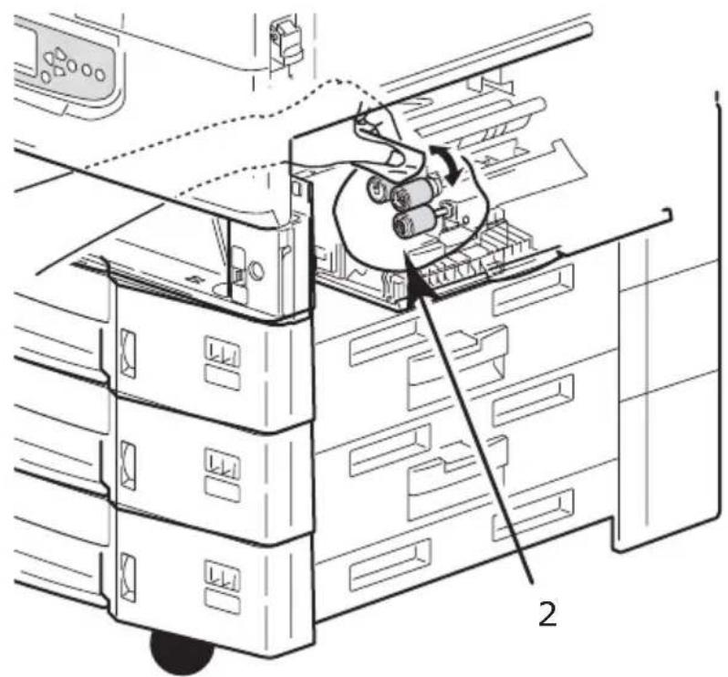
natural_image
Technical diagram of a server rack with a hand inserting a cable into a rack, showing internal components and no text or symbols.- Replace Tray 1.
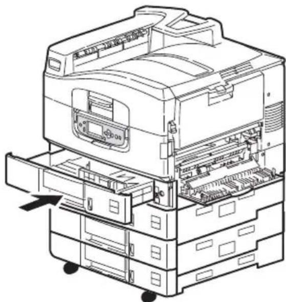
natural_image
Technical line drawing of an open stacked printer with internal compartments and a door panel (no text or symbols)- Close Tray 1 side cover.
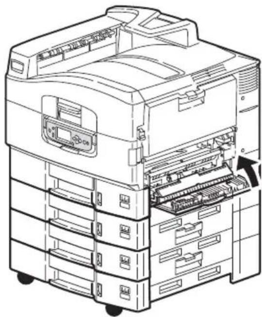
natural_image
Line drawing of an open file organizer with internal components and a directional arrow indicating assembly (no text or symbols present)- Turn on the printer.
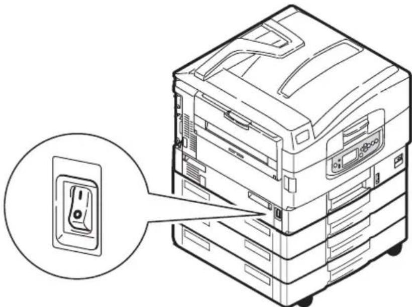
natural_image
Line drawing of a multi-tiered electronic device with an open socket, showing internal components and mounting brackets (no text or symbols)CLEANING THE PRINTER CASING
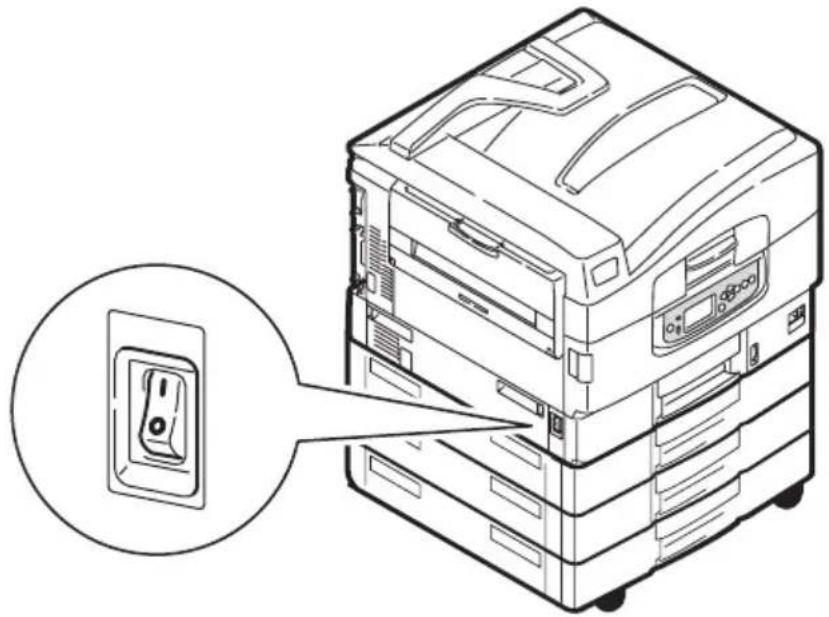
- Turn the printer off by using the Shutdown/Restart button followed by the On/Off switch.
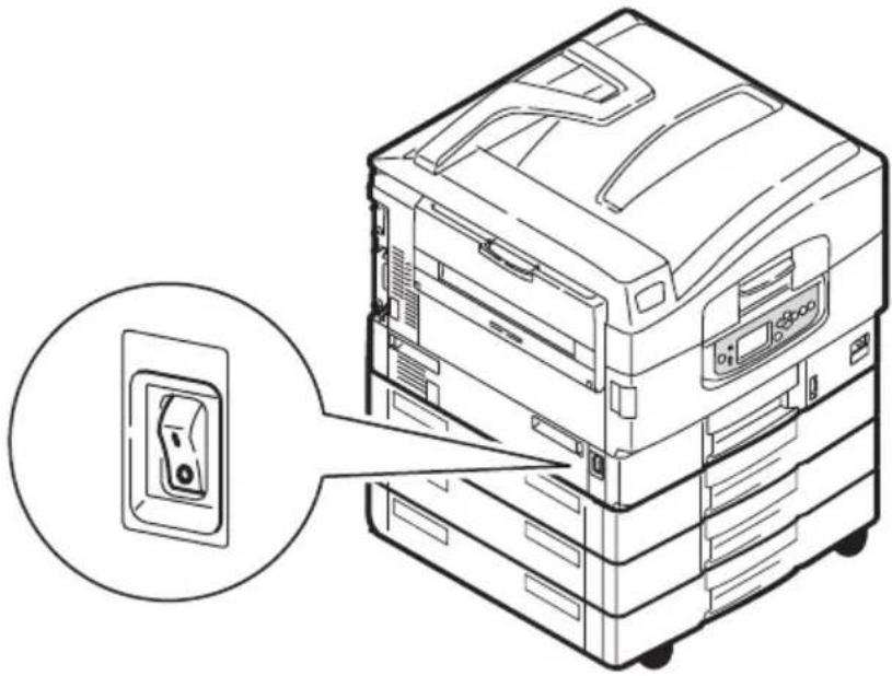
natural_image
Line drawing of a multi-tiered electronic device with an open socket, showing internal components and a magnified inset (no text or symbols)- Wipe the printer surface with a soft cloth moistened sparingly with water or neutral detergent.
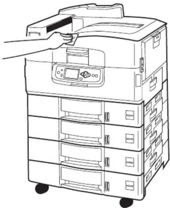
natural_image
Line drawing of a multi-tiered printer with a hand inserting a slot into the top case (no text or symbols)-
Use a soft dry cloth to dry the printer surface.
-
Turn on the printer.
natural_image
Line drawing of a multi-tiered electronic device with an inset showing a small component (no text or symbols)EMPTYING THE OPTIONAL PUNCH CHIP BOX
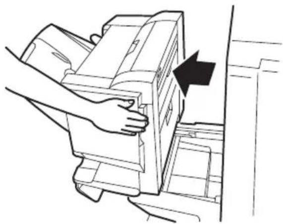
When the LCD panel indicates that the punch chip box is full, empty the box as follows:
- Operate the Finisher lever and move the Finisher away from the printer.
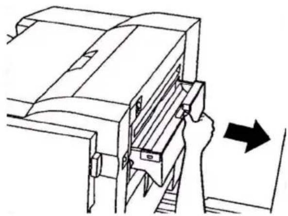
natural_image
Line drawing of a hand pressing a printer into a door, with an arrow indicating the press direction (no text or symbols present)- Pull out the punch chip box, being careful to keep it level so as not to spill any chips.
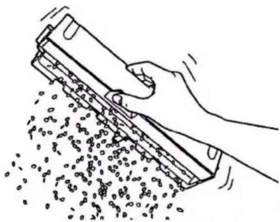
natural_image
Line drawing of a hand inserting a component into a device, with an arrow indicating direction (no text or symbols present)- Discard the chips in an appropriate place.
natural_image
Line drawing of a hand using a tool to spread small objects from a tray (no text or symbols)- Refit the punch chip box carefully into the Finisher.
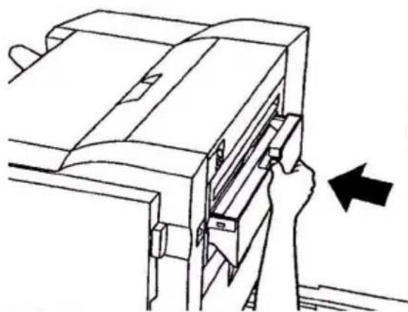
natural_image
Line drawing of a hand inserting a component into a device (no text or symbols)- Check that the punch chip box has been refitted correctly then move the Finisher back into position, being careful not to trap your fingers.
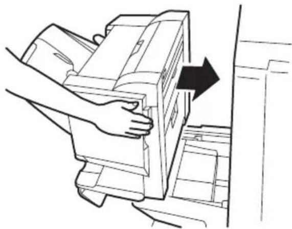
natural_image
Line drawing of a hand pressing a printer into a door, with an arrow indicating the process (no text or symbols present)OPTIONAL ACCESSORIES
This section describes optional accessory equipment for your printer. The following accessories are available:
memory expansion DIMM
second, third paper tray (to increase paper input capacity)
high capacity feeder (equivalent to three paper trays) (C9800hdn only)
NOTE
- Tray configurations are: Tray 1 only, Tray 1 + 2nd Tray, Tray 1 + 2nd Tray + 3rd Tray, Tray 1 + HCF, Tray 1 + 2nd Tray + HCF
- The C9800hdtn already has a High Capacity Feeder installed and so can only accommodate one additional tray (to give the maximum total of five).
Finisher (for stapling or saddle stitching printer output)
Cabinet
Punch unit (to extend Finisher functionality)
MFP Upgrade Kit (for C9800hdn only)
ACCESSORY ORDER INFORMATION
| ITEM ORDER NUMBER | |
| Memory Expansion DIMM | |
| 128 MB | 01163401 |
| 256 MB | 01163402 |
| 512 MB | 01163403 |
| Second, third paper tray 42831303 | |
| High capacity feeder (HCF) 42831503 | |
| Finisher: | |
| 4-tray | 01166701 |
| 5-tray | 01166801 |
| Finisher Punch Unit: | |
| 4 hole | 42872903 |
| 2 hole | 42872901 |
| 4 hole (Sweden) | 42872904 |
| Cabinet (same height as HCF) TBD | |
| MFP Upgrade Kit 01149501 |
INSTALLING ACCESSORIES
Each accessory (apart from the Finisher and MFP Upgrade Kit) comes complete with its own documentation which gives full instructions on installation. You are advised to follow these instructions carefully.
After installation, print out a Menu Map (Configuration document) to check that the installation has been successful.
NOTE
The Finisher, MFP Upgrade Kit and Punch unit must be installed by an authorised engineer.
For the following accessories, you have to make the appropriate setting in your printer driver(s):
paper tray(s)
Finisher
Refer to the Printing Guide for driver setting details.
Once your printer has been upgraded with an MFP Upgrade Kit, refer to the C9800 MFP User's Guide on CD3.
TROUBLESHOOTING
GENERAL
If the printer display panel does not display anything or is still in standby mode 10 minutes after switching on, follow the printer shutdown sequence to switch it off. Check all cable connections before restarting the printer. If the problem persists, contact your dealer.
PAPER JAMS
This section provides information to help you deal with problems that may arise when using the printer. The following paragraphs describe actions to take in the event of a paper jam and how to deal with unsatisfactory print results. LCD panel messages about paper jams and relevant actions are given in this section while a list of other typical messages and suggested responses is given in "Appendix A – LCD Messages" on page 107.
PAPER JAMS - PRINTER
If a paper jam occurs, a message appears on the LCD panel in the printer Control Panel. You can press the Help button to display guidance on how to clear the jam.
For full details of clearing jams, refer to the following paragraphs, which correspond to the paper jam messages.
OPEN COVER, PAPER JAM, TTTTTT SIDE COVER
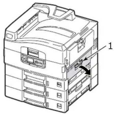
Tray 1, or any one of Tray 2 to Tray 5 (if installed), can appear in place of the tttttt characters in the LCD panel message. In this example Tray 1 is used, the procedure being similar for all other trays.
- Squeeze the catch (1) on Tray 1 side cover and open the cover.
natural_image
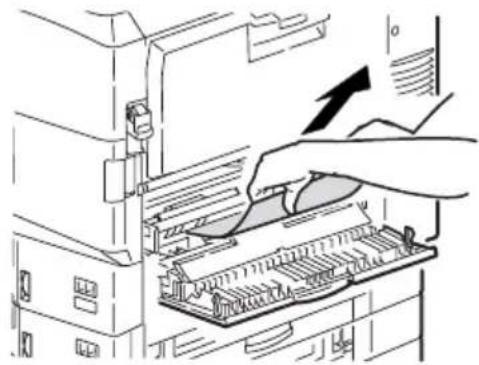
Technical line drawing of a printer internal structure with labeled component (no text or symbols beyond label)- Carefully remove the jammed paper.
natural_image
Illustration of a hand inserting a component into a computer drive (no text or symbols visible)- Close Tray 1 side cover.
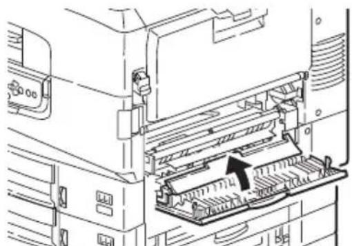
natural_image
Technical line drawing of a mechanical device with internal components and a highlighted section (no text or symbols)OPEN COVER, PAPER JAM, SIDE COVER
- If the MP Tray is open, close it so that the side cover (1) is visible.
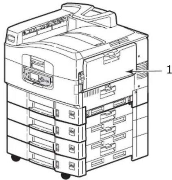
text_image
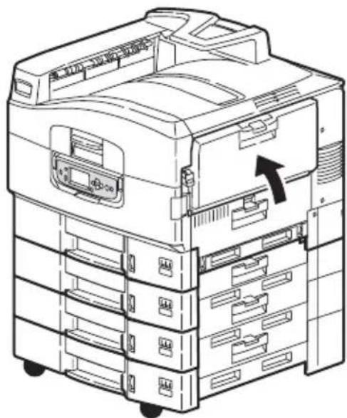
Technical diagram of a multi-tiered printer with labeled parts and component annotations- Pull the release lever (2) and pull open the side cover.
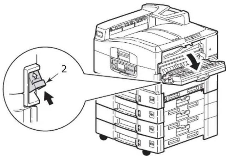
text_image
Diagram illustrating a printer's internal structure and assembly, with labeled parts and directional arrows indicating process flow.- Carefully remove the jammed paper.
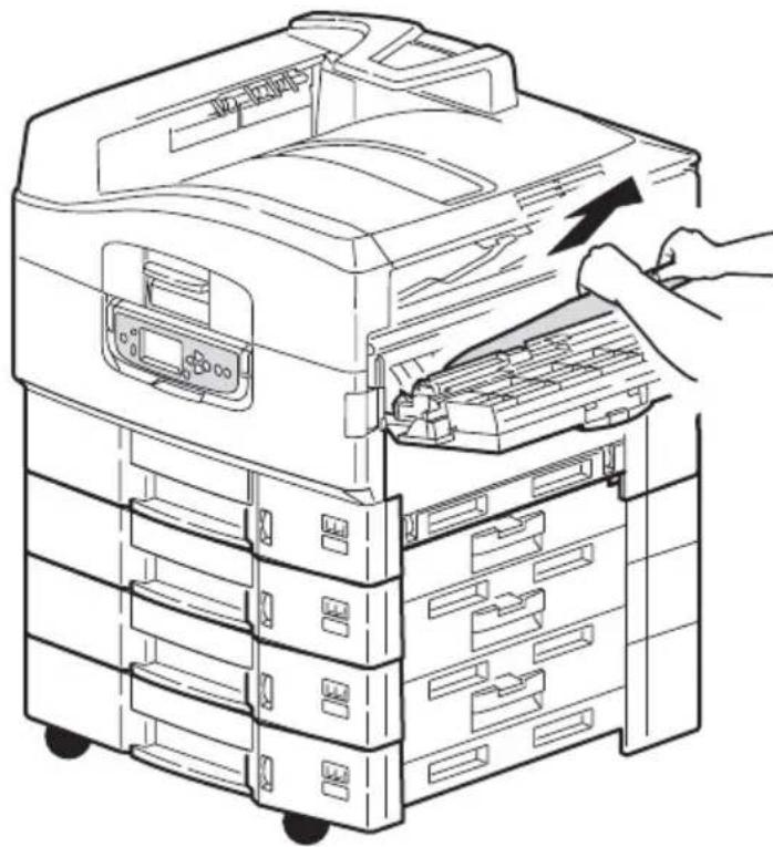
natural_image
Line drawing of a file organizer with hand inserting a folder into the rack (no text or symbols)- Close the side cover.
natural_image
Technical line drawing of a multi-tiered printer or scanner with internal components and a directional arrow indicating movement (no text or symbols present)OPEN COVER, PAPER JAM, TOP COVER
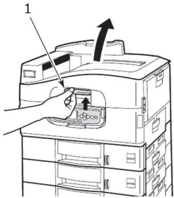
- Squeeze the top cover handle (1) and open the top cover.
text_image
1WARNING!
Be careful not to touch the fuser unit which is hot after printing.
- Squeeze the basket handle (2) and raise the drum basket.

natural_image
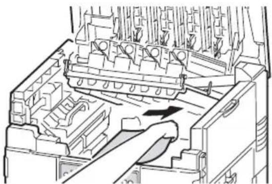
Technical line drawing of an internal server rack with labeled components (no text or symbols present)- Carefully remove any paper on the belt.
natural_image
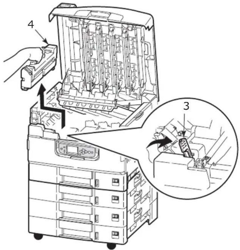
Technical line drawing of a mechanical assembly with internal components and a directional arrow (no text or symbols)- If paper is jammed in the fuser unit, push the lock lever (3) in the direction shown to release the unit.
WARNING!
Be careful not to touch the fuser unit which may be hot after printing. If the fuser unit is hot, wait until it cools before attempting to remove any jammed paper.
Holding the fuser unit (4) by the handle, lift it out of the printer and place it on a flat surface.
text_image
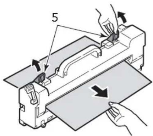
Technical diagram of a device with labeled parts and an inset showing mechanical assembly steps- Pull up the jam release levers (5) and remove the jammed paper.
text_image
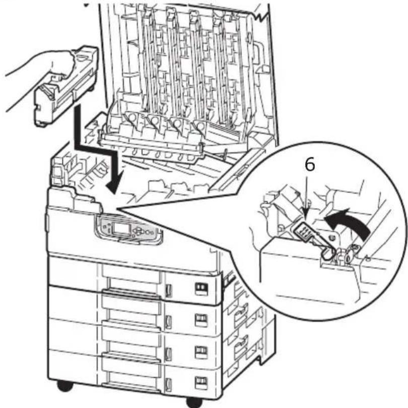
5- Carefully replace the fuser unit into the printer and turn the lock lever (6) in the direction shown to lock the fuser unit.
text_image
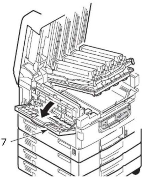
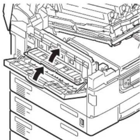
Technical diagram showing a mechanical assembly with labeled parts and a magnified inset highlighting a specific component.- If paper is jammed near the paper exit, open the face-up stacker (7).
natural_image
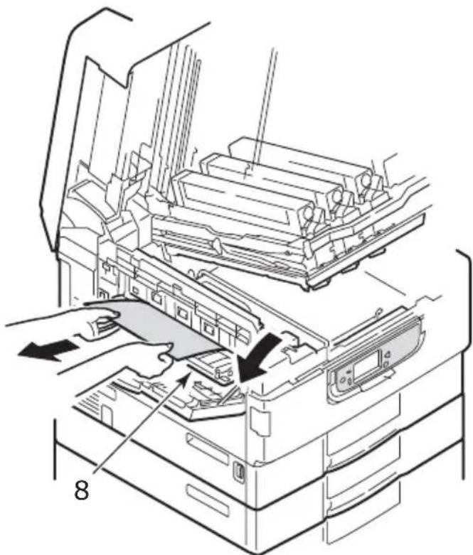
Technical line drawing of an open industrial machine with internal components and a numbered annotation (7), no readable text or symbols present.- Open the side cover (paper exit) (8) and remove the jammed paper.
natural_image
Diagram of a printer's internal structure showing paper feeding into a tray, with no visible text or symbols.- Close the side cover (paper exit) and then the face-up stacker.
natural_image
Technical line drawing of a printer internal structure showing internal components and mounting points (no text or symbols)- Return the image drum basket (9) into position and check it is locked.
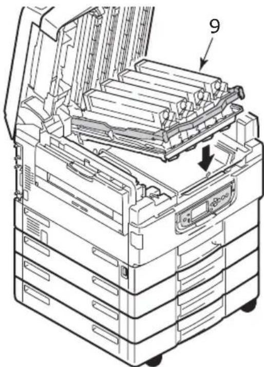
text_image
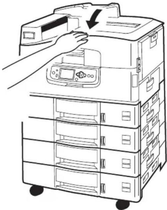
9- Close the top cover and ensure it is latched.
natural_image
Line drawing of a hand operating a multi-tiered printer with a downward arrow indicating compression or disassembly (no text or symbols present)PAPER JAMS - DUPLEX UNIT
CHECK DUPLEX UNIT, PAPER JAM
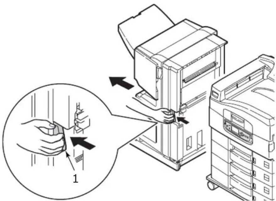
- If a Finisher unit is attached to your printer, operate the lever (1) of the Inverter unit to separate the Inverter from the printer.
text_image
Diagram illustrating a printer press operation with labeled parts and directional arrows indicating process flow.- Operate the duplex cover release button (2) and open the cover.

natural_image
Technical line drawing of a mechanical device with an inset showing a close-up of a component (no text or symbols present)- Carefully remove any jammed paper then close the cover.
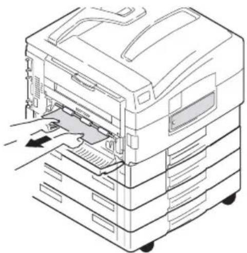
natural_image
Line drawing of a printer with a hand inserting a card into the rack (no text or symbols)- Operate the levers (3) and pull out the duplex unit.
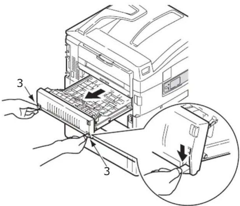
text_image
Diagram showing hands operating a printer with labeled parts and a magnified view of the device's internal structure.- Holding the front top cover by the grip (4), push it gently inwards and raise it.
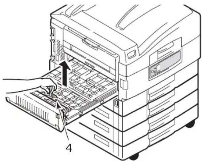
natural_image
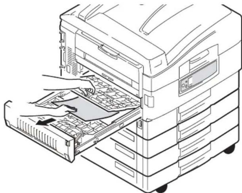
Line drawing of a file organizer with an open drawer and labeled component '4' (no text or symbols on the diagram itself)- Remove any jammed paper.
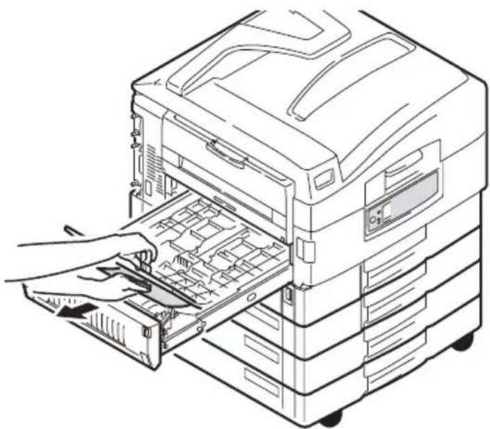
natural_image
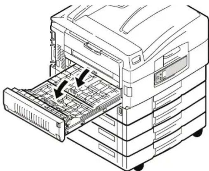
Line drawing of a hand inserting a file into an open rack-mounted machine (no text or symbols visible)- In similar manner, check for and clear any paper jammed under the rear top cover.
natural_image
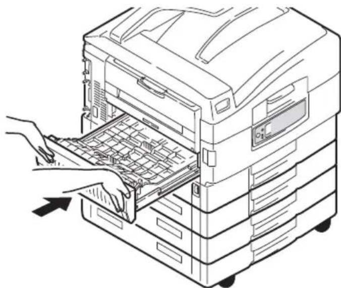
Line drawing of a computer rack with a hand inserting a component into the drawer (no text or symbols)- Replace the two top covers.
natural_image
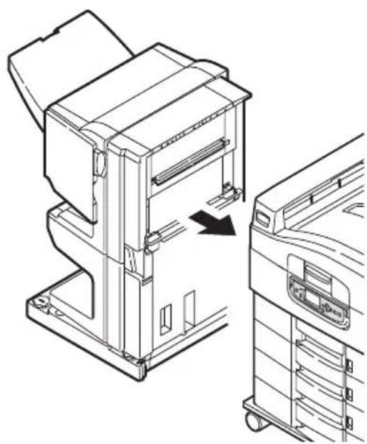
Line drawing of a mechanical device with internal components and two arrows indicating flow or movement (no text or symbols present)- Push the duplex unit back into position.
natural_image
Line drawing of a printer drawer with hands installing or opening the tray (no text or symbols)- If you detached a Finisher unit to gain access to the duplex unit, replace the Finisher unit.
natural_image
Technical line drawing of a printer assembly with an arrow indicating a process (no text or symbols present)PAPER JAMS - FINISHER (OPTIONAL ACCESSORY)
CHECK FINISHER, PAPERJAM /PAPER REMAINS
Use the Help button on the printer control panel to check the number displayed. You will need this to be able to clear the paper jam. The following paragraphs explain what to do for each of the indicated numeric codes.
591, 592, 593, 599/643, 645 (PAPER JAM AROUND FINISHER)
- Remove any paper at the Finisher paper exit.
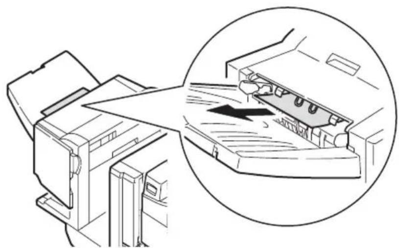
natural_image
Diagram showing a printer feeding into a device with an inset magnified view of the device's internal structure (no text or symbols present)- Operate the Finisher lever (1) and move the Finisher away from the Inverter.
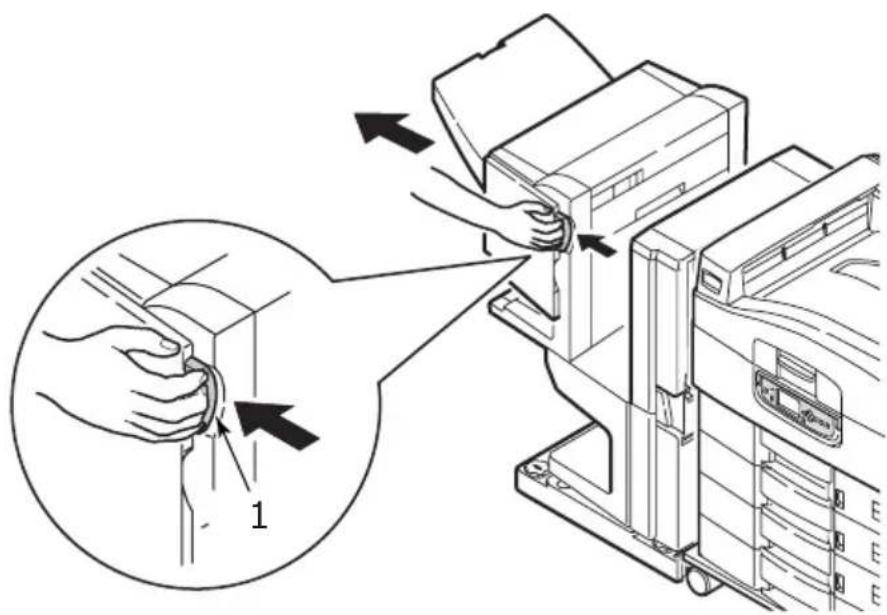
text_image
Diagram illustrating a hand operating a printer to adjust or install a device, with an inset showing the step of adjustment.- Open the Finisher top cover.
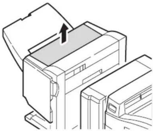
natural_image
Line drawing of a printer with an arrow indicating the paper's front cover (no text or symbols present)- Carefully remove any jammed paper.
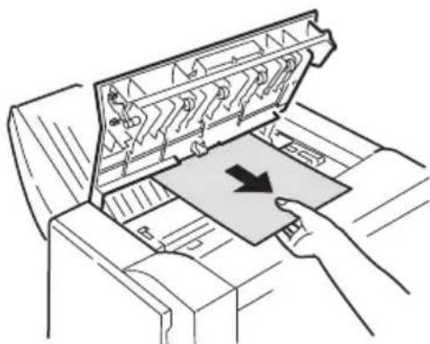
natural_image
Illustration of a printer printer with a hand inserting a paper into it (no text or symbols visible)- Close the Finisher top cover.
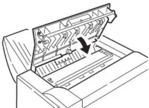
natural_image
Line drawing of a printer's internal structure showing internal components and a downward arrow indicating a process (no text or symbols present)- Move the Finisher back into position and connect it to the Inverter.
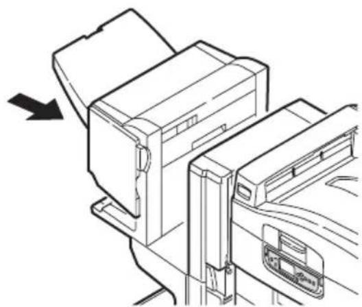
natural_image
Line drawing of a printer or printer device with an arrow indicating direction (no text or symbols present)594, 597, 598/ 644, 646 (PAPER JAM IN FINISHER)
- Operate the Finisher lever (1) and move the Finisher away from the Inverter.
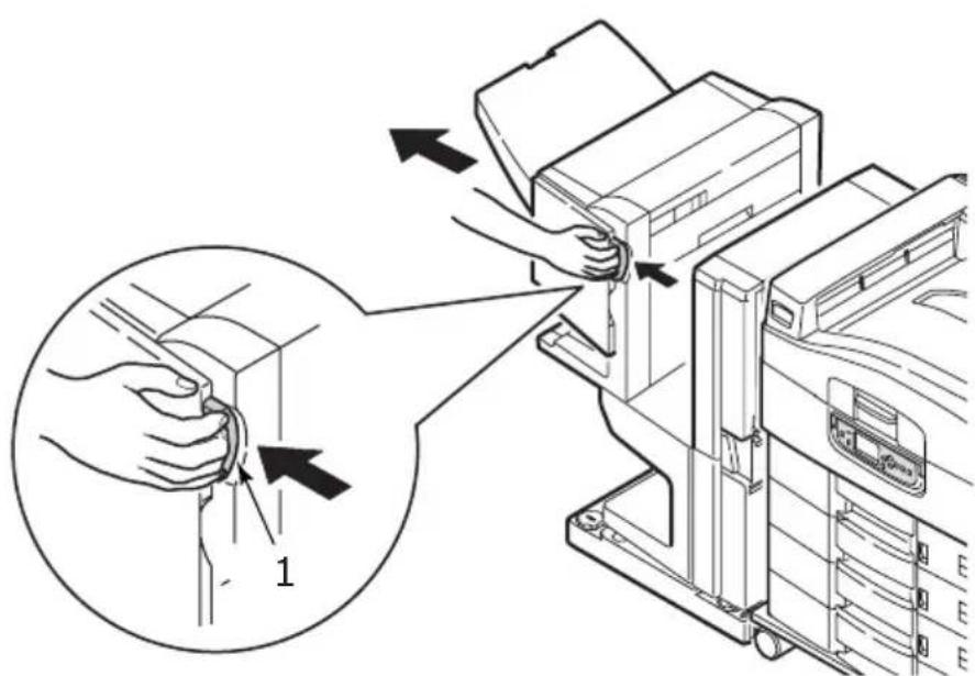
text_image
Technical diagram showing a hand operating a printer with an inset close-up highlighting the component '1'.- Open the Finisher front cover (2).
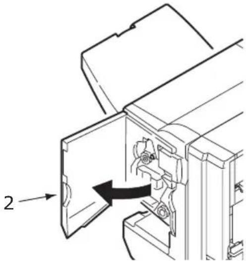
natural_image
Technical line drawing of a mechanical assembly with a labeled component (no text or symbols present)- Continue to turn the lower knob (3) clockwise until any jammed paper is completely ejected.

natural_image
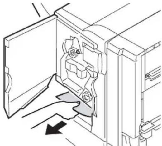
Technical line drawing of a mechanical assembly with labeled parts (no text or symbols)- Remove the ejected paper.
natural_image
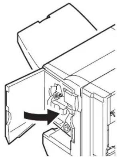
Technical line drawing of a door mechanism with a hand pressing a button (no text or symbols)- Close the Finisher front cover.
natural_image
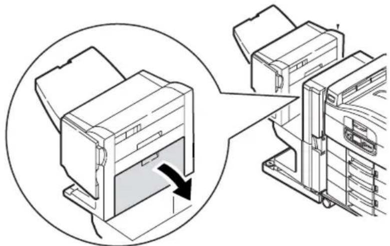
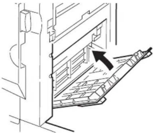
Technical line drawing of a mechanical assembly with an arrow indicating a component (no text or symbols present)- Open the Finisher right side cover.
natural_image
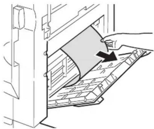
Diagram showing a printer being inserted into a rack, with no visible text or symbols- Carefully remove any jammed paper.
natural_image
Illustration of a hand pressing down on a mechanical component with a curved blade and grid pattern (no text or symbols)- Close the Finisher right side cover.
natural_image
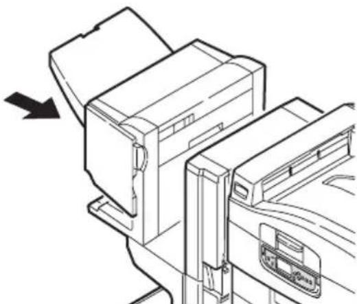
Technical line drawing of a mechanical assembly with an arrow indicating direction (no text or symbols present)- Move the Finisher back into position and connect it to the Inverter.
natural_image
Line drawing of a printer or printer device with an arrow indicating left motion (no text or symbols present)590 (PAPER JAM IN FINISHER/PUNCH UNIT)
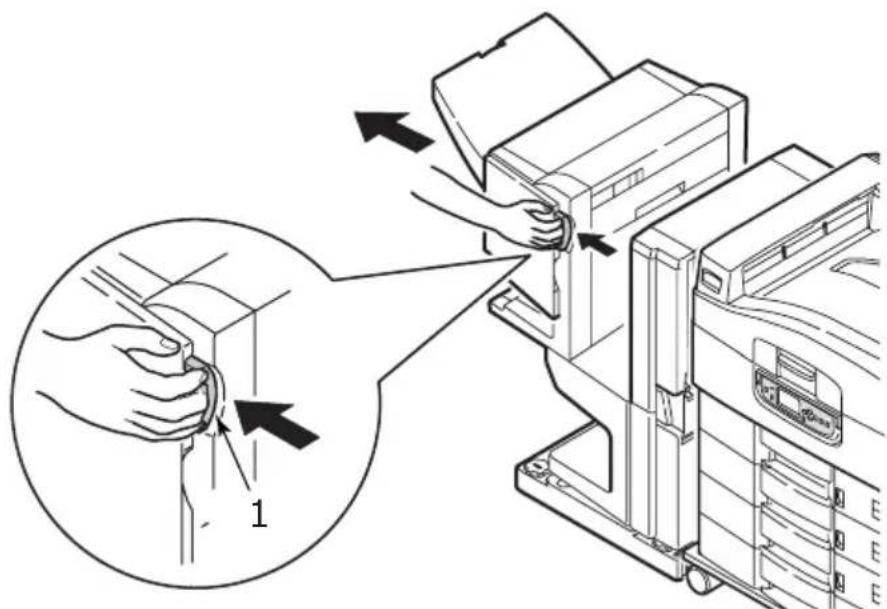
- Operate the Finisher lever (1) and move the Finisher away from the Inverter.
text_image
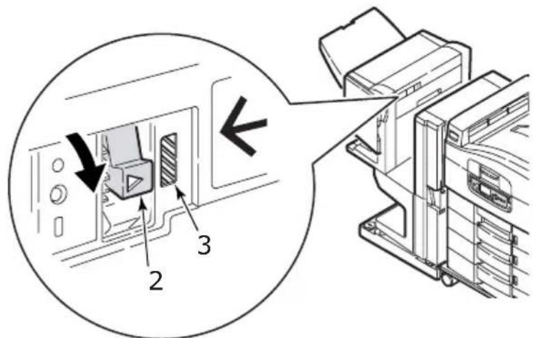
Technical diagram showing a hand inserting a component into an air conditioner unit, with labeled parts and directional arrows.- Move the tab (2) on the right side of the Finisher to align it with the mark (3).
text_image
Technical diagram showing a device with labeled components and directional arrows indicating assembly or operation.- Open the Finisher top cover.
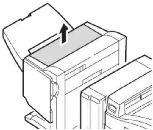
natural_image
Line drawing of a printer with an open lid and paper outlet, showing a paper roll being inserted (no text or symbols)- Carefully remove any jammed paper.
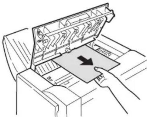
natural_image
Illustration of a printer printer with a paper tray and arrow indicating print direction (no text or symbols)- Close the Finisher top cover.
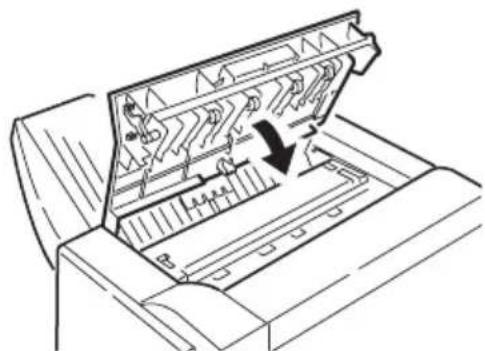
natural_image
Technical line drawing of a printer or printer with internal components and a downward arrow indicating a process (no text or symbols present)- Move the Finisher back into position and connect it to the Inverter.
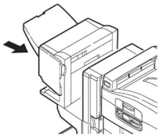
natural_image
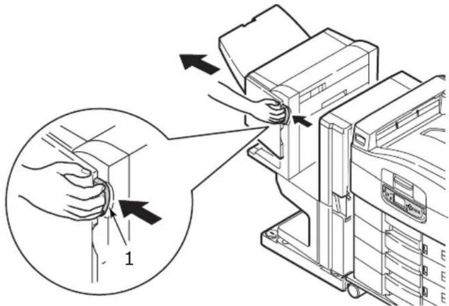
Technical line drawing of a printer or printer device with an arrow indicating direction (no text or symbols present)CHECK INVERTER, PAPER JAM
- Operate the Finisher lever (1) and move the Finisher away from the Inverter.
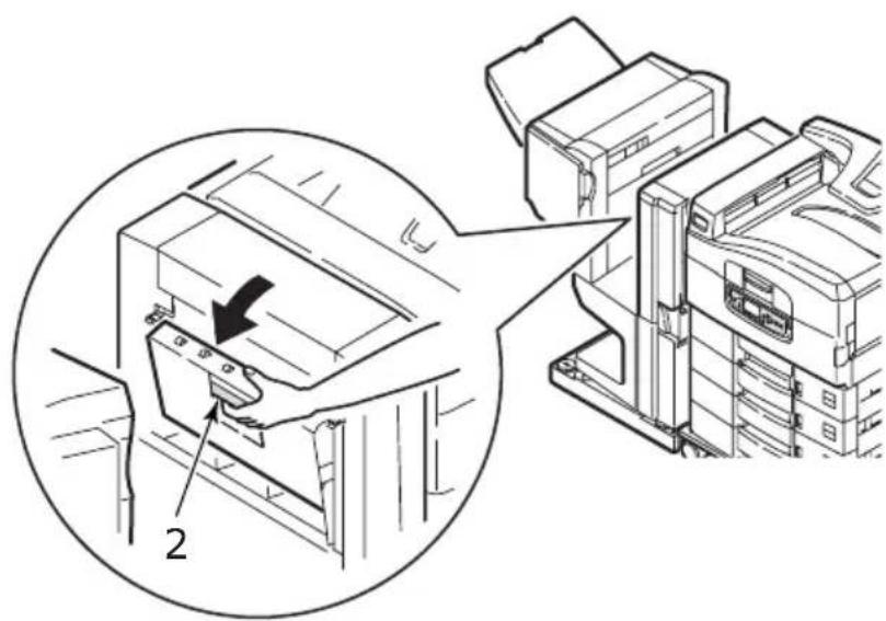
text_image
Diagram illustrating a hand operating a printer with labeled parts and directional arrows indicating process steps.- Squeeze the recessed handle (2) and open the left side cover of the Inverter.
text_image
Technical diagram showing a mechanical assembly with labeled component '2' and directional arrow indicating motion or assembly.- Carefully remove any jammed paper.

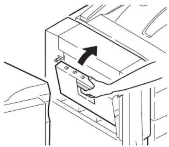
natural_image
Illustration of a hand inserting a card into a printer (no text or symbols visible)- Close the Inverter left side cover.
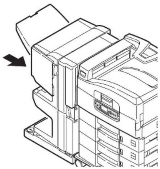
natural_image
Line drawing of a car interior showing a door handle and seatbelt mechanism (no text or symbols)- Move the Finisher back into position and connect it to the Inverter.
natural_image
Technical line drawing of a printer or printer assembly with no visible text or symbols- Operate the Inverter lever (3) and separate the Inverter from the printer.
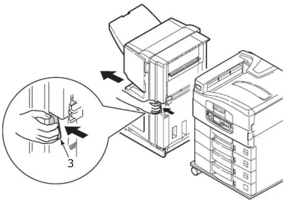
text_image
Diagram illustrating a printer press operation with labeled parts and directional arrows indicating process flow.- Open the right side door (4) of the Inverter.
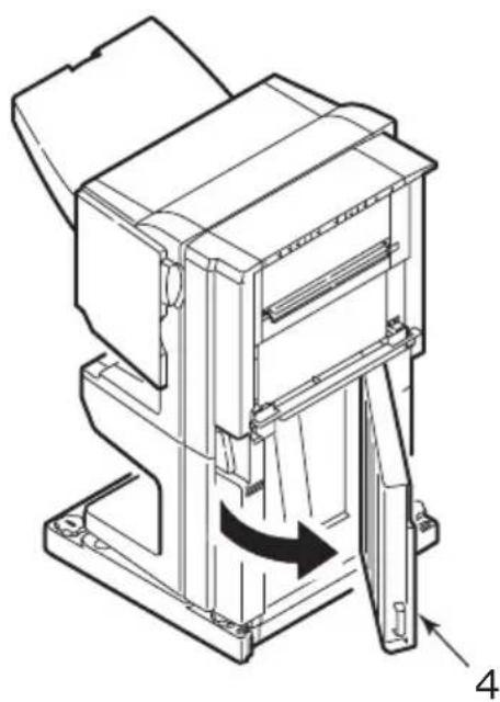
natural_image
Technical line drawing of a mechanical device with a rotating arrow indicating motion (no text or symbols)- Remove any jammed paper.
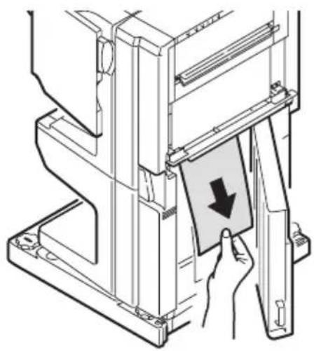
natural_image
Technical line drawing of a mechanical assembly with a hand pressing a component (no text or symbols)- Close the right side door.
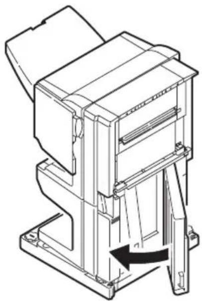
natural_image
Technical line drawing of a mechanical assembly with a directional arrow indicating movement (no text or symbols present)- Move the Finisher and Inverter back into position and connect to the printer.
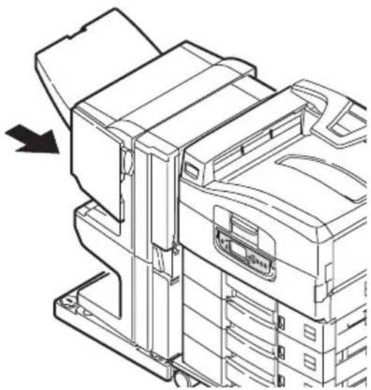
natural_image
Technical line drawing of a mechanical device with an arrow indicating a component (no text or symbols present)AVOIDING PAPER JAMS
The following table summarises possible causes of paper jams and suggests ways of avoiding them.
| POSSIBLE CAUSE SUGGESTED REMEDY | |
| The printer is not level. Place the printer on a steady, level surface. | |
| Your print media is too light or too heavy. | Use appropriate media. |
| Your print media is damp or charged with static electricity. | Use media that has been stored in appropriate temperature and humidity conditions. |
| Your print media is creased or curled. | Use appropriate media. Decurled media can be used. |
| Your print media sheets are not aligned with each other. | Remove the sheets, jog them into alignment and reload them. |
| Your print media is not aligned properly in the paper tray. | Adjust the paper stop and paper guides of the tray, or the manual feed guide on the MP Tray to align the media properly. |
| Your envelopes to be printed are not oriented properly. | Adjust the orientation as required. |
| Your printer feed roller is dirty. | Wipe the roller with a cloth moistened with water. |
| Your printer feed rollers are wearing out. | Replace the feed rollers. |
| The media weight or type have been wrongly set. | Select the correct printer menu settings for [Media Weight] and [Media Type]. |
DEALING WITH UNSATISFACTORY PRINTING
| SYMPTOMS POSSIBLE CAUSES STEPS TO TAKE | ||
| Vertical white lines can be seen on the printed page. | The LED head is dirty. Wipe the LED head with a LED lens cleaner or with a soft cloth. | |
| The toner is low. Replace the toner cartridge. | ||
| Foreign materials may be present in the image drum. | Replace the image drum cartridge. | |
| Light-shielding film of the image drum cartridge is dirty. | Wipe the film with a LED lens cleaner or with a soft cloth. | |
| Printed images are fading vertically. | The LED head is dirty. Wipe the LED head with a LED lens cleaner or with a soft cloth. | |
| The toner is low. Replace the toner cartridge. | ||
| The paper is not suitable for the printer. | Use recommended paper. | |
| Printing is light. The toner cartridge is not properly seated. | Reinstall the toner cartridge. | |
| The toner is low. Replace the toner cartridge. | ||
| The paper is moist. Use paper stored in proper temperature and humidity conditions. | ||
| The paper is not suitable for the printer. Use recommended paper. | ||
| Thickness and type of paper are inappropriate. Set a proper value for [Media Weight] and [Media Type] in the menu setup, or set one value thicker for [Media Weight]. | ||
| Recycled paper is being used. Set one value thicker for [Media Weight] in the menu setup. | ||
| Partially faded images. White spots and lines appear in solid printing. | Paper is moist or dry. Use paper stored in proper temperature and humidity conditions. | |
| Vertical lines appear. | The image drum cartridge is damaged. Replace the image drum cartridge. | |
| The toner is low. Replace the toner cartridge. | ||
| Horizontal Lines and spots appear periodically. | When the interval is about 94mm (4in), the image drum (the green tube) is damaged or dirty. | Wipe it lightly with a soft cloth. Replace the image drum cartridge when it is damaged. |
| When the interval is about 42mm (1.5in), there may be foreign particles in the image drum cartridge. | Open/close the top cover, and print again. | |
| When the interval is about 87mm (3.5in), the fuser unit is damaged. | Replace the fuser unit. | |
| The image drum cartridge has been exposed to light. | Replace the image drum cartridge if the problem is not resolved. | |
| White area of paper is lightly stained. | Paper contains static. Use | paper stored in proper temperature and humidity conditions. |
| Too thick paper is used. Use | thinner paper. | |
| The toner is low. Replace | the toner cartridge. | |
| Periphery of the letters is smudged. | The LED head is dirty. Wipe | the head with LED lens cleaner or with a soft cloth. |
| Toner comes off when it is rubbed. | The thickness and type of the paper are incorrectly set. | Set the correct value of [Media Type] and [Media Weight] in the menu setup or set one value thicker for [Media Weight]. |
| Recycled paper is used. Set one value thicker for [Media Weight] in the menu setup. | ||
| Glossiness is not uniform. | The thickness and type of the paper are incorrectly set. | Set the correct value of [Media Type] and [Media Weight] in the menu setup or set one value lighter for [Media Weight]. |
STAPLE JAMS - FINISHER (OPTIONAL ACCESSORY)
CHECK FINISHER, STAPLE JAM
When the display indicates a staple jam has occurred, clear the jam as follows:
- Open the Finisher front cover.
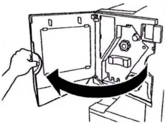
natural_image
Hand holding a device with a curved arrow indicating rotation or change (no text or symbols present)- Turn the knob in the direction indicated until the coloured indicator appears.
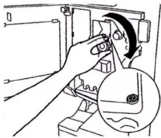
natural_image
Illustration of a hand operating a mechanical device with a magnified inset showing internal components (no text or symbols)- Remove any paper that awaits stapling in the paper ejection area.
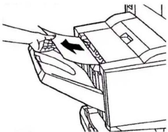
natural_image
Line drawing of a hand pressing down an open door with a black arrow indicating the press direction (no text or symbols present)- Pull out the staple unit.
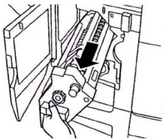
natural_image
Technical line drawing of a mechanical assembly with a hand operating a tool (no text or symbols visible)- Turn the knob in the direction indicated to move the stapler to the front.
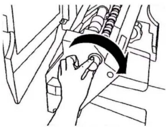
natural_image
Diagram of a hand pressing a button on a vehicle's head panel, showing motion direction (no text or symbols)- Grip both sides of the staple cartridge, pull it up and remove it.
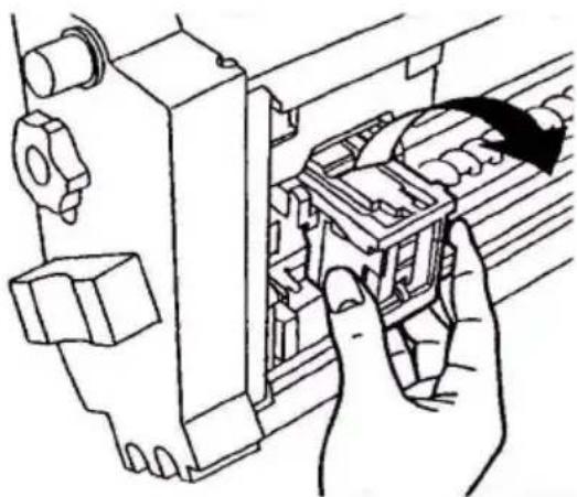
natural_image
Line drawing of hands operating a mechanical device with a directional arrow indicating motion (no text or symbols present)- Raise the staple cartridge gate.
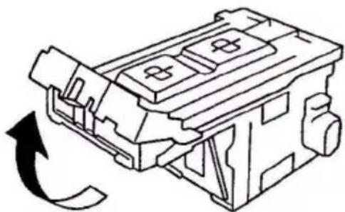
natural_image
Technical line drawing of a mechanical component with a curved arrow indicating rotation (no text or symbols)- Remove all staples that are emerging from the staple case.
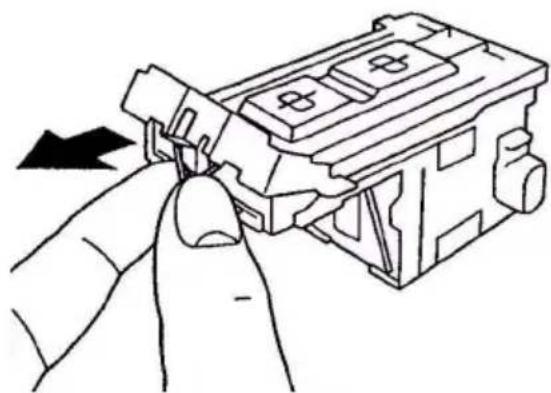
natural_image
Hand inserting a component into a device housing (no text or symbols visible)- Return the staple cartridge gate to its original position.
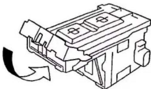
natural_image
Technical line drawing of a mechanical component with no visible text or symbols- Refit the staple cartridge.
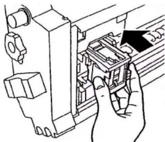
natural_image
Hand inserting a component into a device (no text or symbols visible)- Ensure that the staple cartridge is securely installed back into the staple unit then push the staple unit fully home.
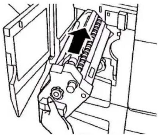
natural_image
Technical line drawing of a mechanical assembly with a hand operating a tool (no text or symbols present)- Close the Finisher front cover, being careful not to trap your fingers.
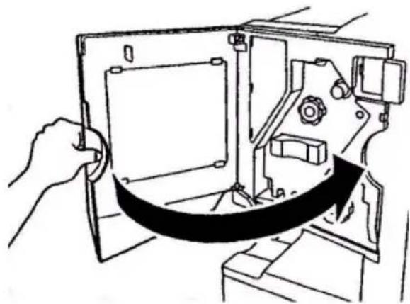
natural_image
Line drawing of a hand holding a device with a belt, showing internal components without any text or symbolsSPECIFICATIONS
| ITEM SPECIFICATION | |
| Dimensions 655x620x462mm (WxDxH) | |
| Weight Without options, 76kg | |
| Print speeds 36 ppm colour; 40 ppm monochrome | |
| Resolution 1200 x 1200 dpi | |
| Emulations PCL 5c, PCL XL 2.1, PS | |
| Memory 1 GB (max.) | |
| Paper input at 80g/m2 | Trays 1 - 5: 530 sheets A4 eachMP Tray: 230 sheets A4 |
| Paper weight 64 - 268g/m2 | |
| Paper output Face-down stacker: 500 sheetsFace-up stacker: 250 sheets | |
| Interfaces Parallel, USB 2.0, 10Base-T and 100Base-TX | |
| Duty cycle 150,000 pages/month maximum | |
| Toner life 15,000 A4 pages @ 5% coverage | |
| Image drum life 30,000 A4 pages | |
| Belt life | 100,000 A4 pages |
| Fuser life 100,000 A4 pages | |
| Waste toner container life | 30,000 A4 pages @ 5% coverage |
| Power rating | 220 - 240 VAC, 50/60 Hz 6A |
| Power consumption | Operating: 1,500 W maximum, 750 W typicalStandby: 1,300 W maximum, 200 W typicalPower save: <45 W |
| Operating environment | Operating: 10 - 32°C/20 - 80%RHOff: 0 - 43°C/10 - 90%RH |
| Noise level Operating: 54dBA maximumStandby: 40dBA maximumPower save: 40dBA maximum after 30 mins background level | |
APPENDIX A - LCD MESSAGES
The LCD panel messages are intended to be self-explanatory. Representative messages are given as examples below.
| MESSAGE COMMENT | |
| Ready to Print Your printer | is online and ready to print. |
| Printing tttttt Your printer | is printing and paper is currently being fed from tttttt, where tttttt identifies a tray. |
| tttttt Near End The paper | supply in the tray identified by tttttt will run out soon. |
| ccccc Toner Low The rem | aining toner of colour cccccc is running low. |
| Fuser Unit Near Life The f | user unit is nearing the end of its working life. |
| Change Fuser Unit The fuser | unit has reached the end of its working life and has to be changed. |
| Inverter is Removed The Inverter unit has been separated from the printer and all Finisher functions are disabled.(Finisher/Inverter is an optional accessory.) | |
| Invalid DataPress ONLINE Button | Invalid data has been received by the printer. Press the ONLINE button to clear this warning. |
| Change Paper in tttttt mmmmmmpppppPress ONLINE buttonPlease see HELP for details | There is a mismatch between the media in the tray and print data.Load media of size mmmmmm and type pppppp into tray tttttt. The message may remain for some time after you have closed the tray.You can have the printer ignore this error for the current print job by pressing the ONLINE button.You can access help details by pressing the HELP button. |
| Install PaperttttttmmmmmmmPlease see HELP for details | The printer has tried to take paper from an empty tray.Load media of size mmmmmm into tray tttttt. The message may remain for some time after you have closed the tray.You can access help details by pressing the HELP button. |
| Install Traytttttt | The printer has tried to take paper from a tray that has been removed.Ensure that tray tttttt is correctly located or put tray tttttt loaded with paper back into the printer. |
| Open CoverPaper Remains ttttttPlease see HELP for details | Additional paper has been detected after a paper jam has been cleared.Open tttttt side cover to check for additional paper.You can access help details by pressing the HELP button. |
| Check Image Drum ccccccePlease see HELP for details | Check that the image drum of colour ccccccc is correctly installed.You can access help details by pressing the HELP button. |
| Incompatible Toner ccccccc | Toner cartridge of colour ccccccc is not compatible and must be replaced by a genuine cartridge. |
The top-level Functions menus are:
Configuration
Print Pages
Suspend Printing
Resume Printing
Print Secure Job
Menus
Shutdown
Admin Setup
Calibration
Print Statistics
The other special top-level menu is:
System Maintenance
The following tables summarise the Configuration, Print Pages, Print Secure Job and Menus menu trees and provide some usage examples. The menu trees are given to the lowest menu item level. Typically, this can be a parameter that can be set by selecting from a range of values provided or a command that can be executed to display or print a status or setting value.
Emboldened values followed by an (A) denote default values associated with locations where A4 is default paper size. Emboldened values followed by an (L) denote default values associated with locations where Letter is default paper size. Emboldened values followed by neither (A) nor (L) denote common defaults.
Certain menus and items associated with, for example, the Finisher appear only if the associated hardware is installed or under certain conditions.
The remainder of the menus above are intended for more specialised usage and are not described further here. For full details of using all menus to configure and use the printer, refer to the Configuration Guide.
CONFIGURATION
PRINT PAGE COUNT
| ITEM VALUE DESCRIPTION | ||
| Colour Page nnnnnn Displays number of | colour printed pages converted to A4 equivalent. | |
| Monochrome Page | nnnnnn Displays number of | monochrome printed pages converted to A4 equivalent. |
| Traym nnnnnn Displays total printed | pages from Traym, where m is in range 1 to 5. | |
| MP Tray nnnnnn | Displays total printed | pages from MP tray. |
FINISHER COUNT
| ITEM VALUE DESCRIPTION | ||
| Staple nnnnnn Displays total pages | stapled. | |
| Punch nnnnnn Displays total pages | punched. | |
| Finisher nnnnnn | Displays total pages | ejected into the Finisher. |
SUPPLIES LIFE
| ITEM VALUE DESCRIPTION | ||
| xxxx Drum Remaining nnn% Displays the remaining | life span of the xxxdrum as a percentagewhere xxx can beCyan, Magenta, Yellow,Black. | |
| Belt | Remaining nnn% | life span of the belt unitas a percentage. |
| Fuser | Remaining nnn% | Displife span of the fuserunit as a percentage. |
| xxxx Toner(n.nK) | Remaining nnn% Displays the remaining | life span of xxx toneras a percentage, wherexxxx can be Cyan,Magenta, Yellow, Black.(n.nK) indicates thecapacity of the tonercartridge being used. |
NETWORK
The items and settings displayed are specific to your system. Full details are given in the Configuration Guide.
PAPER SIZE IN TRAY
| ITEM VALUE | DESCRIPTION | |
| Traym where m is in range 1 to 5(similar arrangement for all trays) | ExecutiveLetter Short EdgeLetter Long EdgeLegal 14Legal 13.5TabloidTabloid ExtraLegal 13A6A5A4 Short EdgeA4 Long EdgeA3A3 NobiA3 WideB5 Short EdgeB5 Long EdgeB4PostcardDouble PostcardCustom | Displays detected paper size of Traym. |
| MP Tray Similar | to values for Traym Displays detected paper size of the MP Tray. | |
SYSTEM
| ITEM VALUE | DESCRIPTION | |
| Serial Number | xxxxxxxxxxxxx Displays serial no. of the printer. | |
| Asset Number | xxxxxx Displays Asset Number. | Asset Number is 8 alphanumeric characters that can be assigned by a user. Same as Asset Number of Menu Map. |
| CU Version | xx.xx Displays version no. of | CU (Control Unit) firmware.Same as CU version of Menu Map. |
| PU Version | xx.xx.xx Displays version no. of | PU (Print Unit) firmware.Same as PU version of Menu Map. |
| ITEM VALUE DESCRIPTION | ||
| Total Memory xx | MB Displays total RAM | memory installed in the printer.Same as Total Memory of Menu Map. |
| HDD xx.xx GB [Fxx] | Displays size of hard | disk and file system version.Same as HDD of Menu Map. |
CONFIGURATION EXAMPLE - MONOCHROME PAGES PRINTED
To display the total monochrome pages printed so far (remembering that a duplex page counts as two pages):
- Ensure that the LCD panel indicates that the printer is ready to print.
- Enter menu mode by pressing either the Up-arrow or Down-arrow button and press them repeatedly until the Configuration menu is highlighted.
- Press the Enter button to select this menu.
- Press the Up-arrow or Down-arrow buttons repeatedly until Print Page Count is highlighted.
- Press the Enter button to select this Item.
- Press the Up-arrow or Down-arrow buttons repeatedly until Monochrome Page is highlighted.
- Press the Enter button and the monochrome page count is displayed.
- Press the Online button to exit menu mode and return to the ready to print status.
PRINT PAGES
| ITEM VALUE | DESCRIPTION | |
| PS Test Page | Execute Prints the | PostScript sample page. |
| Configuration | Execute Prints printer | configuration details. |
| Job Log Execute | Prints EFI job log | details. |
| Color Charts (disk only) | Execute Prints colour | charts. |
| PS Font List | Execute Prints PostScript | font list. |
| PCL Font List | Execute Prints PCL | emulation font list. |
| Demo Page (disk only) | Execute Prints a demo | page. |
| Usage Report (disk only) | Execute Prints usage | report. |
| Statistics Log (disk only) | Execute Prints Oki job log | details. |
| Error Log Execute | Prints the error | log. |
| E-mail Log (disk only) | Execute Prints e-mail log. | |
| PrintMe Log (disk only) | Execute Prints PrintMe | Log. |
PRINT INFORMATION EXAMPLE - DEMONSTRATION PAGE
To print a printer demo page to demonstrate how your printer prints:
- Ensure that the LCD panel indicates that the printer is ready to print.
- Enter menu mode by pressing either the Up-arrow or Down-arrow button and press them repeatedly until the Print Pages menu is highlighted.
- Press the Enter button to select this menu.
- Press the Up-arrow or Down-arrow buttons repeatedly until Demo page is highlighted.
- Press the Enter button to select this Item and the demo page is printed.
- After printing, the printer returns to ready to print status.
PRINT SECURE JOB
| ITEM VALUE DESCRIPTION | ||
| Enter Password nnnn Enter a password to use secure printing. | ||
| Not Found Use a secure printing job | (Secure Job) ora job Stored to HDD when printing. Whenyou print a Secure document, it is deletedfrom the HDD. When you print adocument Stored to HDD, it prints andremains stored on the HDD until youmanually delete it.Not Found:(no jobs) is indicated whenthere is no output file.The following messages are displayedwhen there are printable files.Print:When you select Print, SetCollating Amount is displayed to enableyou to specify a number of copies. Afterspecifying the number of copies, pressEnter to print all jobs with the specifiednumber of copies.Delete:When you select Delete, you areprompted to recheck by Yes/No display,and selecting Yes deletes all jobs. | |
| Secure Job Print | Delete | |
TRAY CONFIGURATION
| ITEM VALUE DESCRIPTION | |||
| Paper Feed Tray1 | Tray2Tray3Tray4Tray5MP Tray | Specifies a feed tray.Indicated only when Tray2-5 implemented. | |
| Auto TraySwitch | ONOFF | Sets the automatic tray switch function. | |
| Tra y Sequence Down | UpPaper feed tray | Specifies selection order priority for automatic tray selection/automatic tray switch. | |
| Unit of Measure | Inch (L)mm (A) | Specifies units for custom paper size. | |
| Tra ym Config, where m is in range 1 to 5 (similar arrangement for all trays) | Paper Size Tray SizeCustom | Sets paper in Traym. | |
| X Dimension 3.9 | -8.3 (A) -8.5 (L) - 12.9 inch100 - 210 (A)- 216 (L) - 328 mm | Sets Custom paper width for Traym. Sets for the direction perpendicular to the direction of paper movement. | |
| Y Dimension 5.8 | -11 (L) -11.7 (A) - 18 inch148 - 279 (L)- 297 (A) - 457 mm | Sets Custom paper length for Traym. Sets for the same direction as paper movement. | |
| Media Type Plain | Sets the media type for Traym.User Type1 to User Type5 are reserved for custom paper sizes set in the printer driver. | ||
| ITEM VALUE | DESCRIPTION | ||
| Traym Con fig, where m is in range 1 to 5 (similar arrangement for all trays) | Media Weight | AutoLightMedium LightMediumMedium HeavyHeavyUltra Heavy 1Ultra Heavy 2Ultra Heavy 3 | Sets media weight for Traym. |
| A3 Nobi Paper | A3 NobiA3 WideTabloid Extra | The printer detects A3 Nobi, A3 Wide and Tabloid Extra sizes as the same. Use this setting to tell the printer which of the three sizes is loaded in Traym. | |
| Legal 14 Paper | Legal 14Legal 13.5 | Sets the length of the legal paper in Traym. Change this to Legal 13.5 if that is the standard legal size in your country. | |
| A5/A6 Paper A5/A6Postcard | The printer detects A5, A6 and Postcard sizes as the same. Use this setting to tell the printer which of the three sizes is loaded in Traym. | ||
| MP Tray Config | Paper Size A3 Nobi | A3 WideA3A4 Sht EdgeA4 Long Edge(A)A5A6B4B5 Short EdgeB5 Long EdgeLegal 14Legal 13.5Tabloid ExtraTabloidLetter Sht EdgeLetter LongEdge (L)ExecutiveCustomCom-9EnvelopeCom-10EnvelopeMonarchEnvelopeDL EnvelopeLandscapePostcardDoublepostcardC5C4Envelope IndexCard | Sets paper size for MP Tray. |
| X Dimension 3 | 8.3 (A) -8.5 (L) - 12.9 inch76 - 210 (A) -216 (L) - 328 mm | Sets Custom paper width for the MP Tray. Sets for the direction perpendicular to the direction of paper movement. | |
| Y Dimension 3.5 | -11.0 (L)-11.7 (A) -47.2 inch90 - 279 (L) -297 (A) - 1200 mm | Sets Custom paper length for MP Tray. Sets for the same direction as paper movement. | |
| MP Tray Config M | Media Type Plain | Letterhead Transparency Labels Bond Recycled Card stock Rough Glossy Envelope User Type1 User Type2 User Type3 User Type4 User Type5 | Sets the media type for MP Tray. |
| Media Weight Auto Light Medium Light Medium Medium Heavy Heavy Ultra Heavy 1 Ultra Heavy 2 Ultra Heavy 3 | Sets the media weight for MP Tray. | ||
| Tray Usage Normal Tray Tray selection/switching uses this tray as the normal tray. | |||
| When MismatchingIf a paper size or type in a tray is not matched to that of the print data, use paper from this tray instead of the specified tray. | |||
| Do Not Use Makes the MP tray unavailable in auto tray selection/switching. | |||
SYSTEM ADJUST
| ITEM VALUE DESCRIPTION | ||
| Power Save Time | 5 min15 min30 min60 min240 min | Sets the period after which power save mode starts. |
| Clearable Warning | OnlineJob | When Online is selected, you must manually clear the warning by pressing the Online button. Change to Job if you wish the message to automatically clear when a new print job is received. |
| Auto Continue ON | OFF | Sets whether the printer is automatically recovered when Memory Overflow or Tray Reques t o cours. |
| Manual Timeout | OFF30 sec60 sec | If paper is not fed within this time in manual feed, the job is cancelled. |
| Wait Timeout OFF | 5 sec10 sec20 sec30 sec40 sec50 sec60 sec90 sec120 sec150 sec180 sec210 sec240 sec270 sec300 sec | Sets the time period between stopping receipt of job data and forced print. For PS, printing is not carried out and the job is cancelled. |
| ITEM VALUE DESCRIPTION | |||
| Low Toner Continue Stop | Sets the printing operation when insufficient toner is detected.Continue: the printer can continue printing while remaining online.Stop: the printer stops printing and goes offline. | ||
| Jam Recovery ON OFF | ON: continues printing the job, including any jammed pages, once the jam has been cleared.OFF: Cancels a job including the page currently jammed. | ||
| Print Position Adjust | X Adjust 0.00 | +0.25 - +2.00-2.00 - -0.25 mm0.00+0.01 - +0.08-0.08 - -0.01 in | Adjusts the position of the whole printing image (0.25 mm, 0.01 in interval) perpendicular to the direction of paper movement (i.e. horizontally). |
| Y Adjust 0.00 | +0.25 - +2.00-2.00 - -0.25 mm0.00+0.01 - +0.08-0.08 - -0.01 in | Adjusts the position of the whole printing image (0.25 mm, 0.01 in interval) parallel to the direction of paper movement (i.e. vertically). | |
| Print Position Adjust | Duplex X Adjust 0.00+0.25 - +2.00-2.00 - -0.25 mm0.00+0.01 - +0.08-0.08 - -0.01in | During the flip-side printing of duplex printing, adjusts the location of the whole printing image (0.25 mm, 0.01in interval) perpendicular to the direction of paper movement (i.e. horizontally). | |
| Duplex Y Adjust 0.00+0.25 - +2.00-2.00 - -0.25 mm0.00+0.01 - +0.08-0.08 - -0.01 in | During the flip-side printing of duplex printing, adjusts the location of the whole printing image (0.25 mm, 0.01 in interval) parallel to the direction of paper movement (i.e. vertically). | ||
| xxxx Darkness 0 | +1 - +3-4 - -1 | Adjusts the xxxx engine density where xxxx is one of Cyan, Magenta, Yellow, Black. Darkest value is +3. | |
| xxxx Reg Fine Adjust | 0+1 - +3-3 - -1 | Makes fine adjustment to image registration in xxxx against Black in the horizontal direction, where xxxx is one of Cyan, Magenta, Yellow.If the paper movement direction is upward, a value set on the plus side, means the image relatively moves downward. | |
| Paper Black Setting | 0+1 - +2-2 - -1 | Used for micro adjustment when very visible faded print results or light specks (or streaks) result when printing in Plain Paper/Black setting.Decrease the value if light specks (or streaks) or snow flake like printing results in high density print areas. | |
| Paper Color Setting | 0+1 - +2-2 - -1 | Used for micro adjustment when very visible faded print results or light specks (or streaks) result when printing in Plain Paper/Color setting.Decrease the value if light specks (or streaks) or snow flake like printing results in high density print areas | |
| Transparency Black Setting | 0+1 - +2-2 - -1 | As for Paper Black Setting above. | |
| Transparency Color Setting | 0+1 - +2-2 - -1 | As for Paper Color Setting above. | |
| Drum Cleaning ON OFF | Set to produce idling of a drum before printing in order to reduce horizontal white lines. This shortens image drum life. | ||
| Hex Dump Execute Prints out the data | received from the host PC in hexadecimal code. | ||
MENUS EXAMPLE 1 - TRAY 1 TRANSPARENCIES
To print on transparencies (accommodated in Tray1):
- Ensure that the LCD panel indicates that the printer is ready to print.
- Enter menu mode by pressing either the Up-arrow or Down-arrow button and press them repeatedly until the Menus menu is highlighted.
- Press the Enter button to select this menu.
- Press the Up-arrow or Down-arrow buttons repeatedly until Tray Configuration is highlighted.
- Press the Enter button to select this Item.
- Press the Up-arrow or Down-arrow buttons repeatedly until Tray1 Config is highlighted.
- Press the Enter button to select this Item.
- Press the Up-arrow or Down-arrow buttons repeatedly until MediaType is highlighted.
- Press the Enter button to select this Item.
- Press the Up-arrow or Down-arrow buttons repeatedly to move through the range of media types until Transparency is highlighted.
- Press the Enter button to select this value.
- Check that an asterisk (*) appears beside Transparency.
- Press the Online button to exit menu mode and return to the ready to print status.
MENUS EXAMPLE 2 - MP TRAY PAPER SIZE
To set paper size in the MP Tray:
- Ensure that the LCD panel indicates that the printer is ready to print.
- Enter menu mode by pressing either the Up-arrow or Down-arrow button and press them repeatedly until the Menus menu is highlighted.
- Press the Enter button to select this menu.
- Press the Up-arrow or Down-arrow buttons repeatedly until Tray Configuration is highlighted.
- Press the Enter button to select this Item.
- Press the Up-arrow or Down-arrow buttons repeatedly until MP Tray Config is highlighted.
- Press the Enter button to select this Item.
- Press the Up-arrow or Down-arrow buttons repeatedly until Paper Size is highlighted.
- Press the Enter button to select this Item.
- Press the Up-arrow or Down-arrow buttons repeatedly to move through the range of paper sizes until the required size is highlighted.
- Press the Enter button to select this value.
- Check that an asterisk (*) appears beside the chosen size.
- Press the Online button to exit menu mode and return to the ready to print status.
INDEX
A
accessories 66
installing.... 68
order details 67, 68
arrow buttons 42
B
back button 42
C
cancel button 42
cleaning
feed rollers.... 58
LED heads.... 56
printer casing 62
clearing
paper jams.... 69
staple jams 100
consumables
order details 55
replacing.... 54
control panel
adjusting 41
controls 41
current settings
checking 49
D
display 42
Configuration information...... 44
Help information 44
Menu information 43
messages....107
Status information 43
E
enter button 42
F
features
optional 18
H
help button 42
I
indicator light
attention...... 42
ready 42
interface
Ethernet 50, 51
parallel 49,50
USB 49,51
M
maintenance items
replacing ....54
menu
Admin Setup 109
Calibration 109
Configuration .....109, 110
Menus ......109, 116
Print Information 114
Print Pages.... 109
Print Secure Job......109, 115
Print Statistics 109
Resume Printing 109
Shutdown 109
Suspend Printing.... 109
System Maintenance 109
using....45
0
online button 42
P
paper
duplex printing 33
face-down stacker....33
face-up stacker....33
inputs....31
loading 34
MP tray....32
outputs....31
stackers....39
trays 32
paper jams
avoiding 97
duplex 79
finisher 84
inverter 92
side cover 69
top cover 73
printer
components 24
location 46
specifications.... 105
printing
punch chip box
emptying 63
R
recommended media 30
S
shutdown/restart button......41
software....29
specifications 105
T
troubleshooting 69
turning
off.... 47
on.... 48
U
unsatisfactory printing.... 98
user's guide
printing.... 21
OKI CONTACT DETAILS
Oki Systems (UK) Limited
550 Dundee Road
Slough Trading Estate
Slough, SL1 4LE
Tel:44 (0) 1753 819819
Fax:44 (0) 1753 819899
http://www.oki.co.uk
Oki Systems Ireland Limited
The Square Industrial Complex
Tallaght, Dublin 24, Ireland
Tel:+353 1 4049590
Fax:+353 1 4049591
http://www.oki.ie
Technical Support:
Tel:+353 1 4049570
Fax:+353 1 4049555
E-mail: tech.support@oki.ie
OKI Systems (Ireland) Ltd.
(Northern Ireland)
40 Sydenham Park
Belfast, BT4 1PW
Tel:+44 (0)28 90 20 1110
http://www.oki.ie
Technical Support:
Tel: +44 (0)28 90 221919
E-mail: tech.support@oki.ie
Oki Data Corporation
4-11-22 Shibaura, Minato-ku, Tokyo
108-8551, Japan
Tel:(81) 3 5445 6158
Fax:(81) 3 5445 6189
http://www.okidata.co.jp
Oki Data (Singapore) Pte. Ltd.
78 Shenton Way, #09-01,
Singapore 079120
Tel:(65) 221 3722
Fax:(65)421 1688
http://www.okidata.com.sg
Oki Systems (Thailand) Ltd.
956 Udomvidhya Building 6th Floor,
Rama IV Rd., Bangkok 10500, Thailand
Tel:(662) 636 2535
Fax:(662) 636 2536
http://www.okisysthai.com
Oki Hong Kong Limited
Suite 1909, Tower3,
China Hong Kong City,
33 Canton Rd., Tsimshatsui,
Kowloon, Hong Kong
Tel:(852) 2736 0130
Fax:(852) 2376 3725
The IPL Group
63-85 Victoria Street
Beaconsfield NSW 2015, Australia
Tel:(61) 2 9690 8200
Fax:(61) 2 9690 8300
http://www.oki.com.au
Comworth Systems Ltd.
10 Constellation Drive Mairangi Bay,
Auckland,
New Zealand
Tel:(64) 9 477 0500
Fax:(64) 9 477 0549
http://www.comworth.co.nz
OKI EUROPE LIMITED
Central House
Balfour Road
Hounslow TW3 1HY
United Kingdom
Tel: +44 (0) 208 219 2190
Fax: +44 (0) 208 219 2199
WWW.OKIPRINTINGSOLUTIONS.COM