
DSX4500 - Car radio Crunch - Free user manual and instructions
Find the device manual for free DSX4500 Crunch in PDF.


| Product Type | Car Stereo |
| Brand | Crunch |
| Model | DSX4500 |
| Dimensions (approx) | 7 x 7 x 2 inches (1-DIN) |
| Weight | 2.2 lbs |
| Power Supply | 12V DC |
| Peak Power Output | 4 x 50 Watts |
| Radio Tuner | AM/FM with RDS |
| Audio Playback | CD, MP3, WMA |
| Inputs | AUX (3.5mm), USB, Front |
| Outputs | 4 Speaker Channels, 2 Preamp (RCA) |
| Display | LCD with White Illumination |
| Remote Control | Included |
| Security | Detachable Faceplate |
| Installation Size | DIN Standard |
| Equalizer | Preset EQ Modes (Rock, Pop, etc.) |
| Maintenance | Clean with Soft Dry Cloth |
| Spare Parts Availability | Contact Crunch Support |
| Warranty | Limited 1 Year |
Frequently Asked Questions - DSX4500 Crunch
User questions about DSX4500 Crunch
0 question about this device. Answer the ones you know or ask your own.
Ask a new question about this device
Download the instructions for your Car radio in PDF format for free! Find your manual DSX4500 - Crunch and take your electronic device back in hand. On this page are published all the documents necessary for the use of your device. DSX4500 by Crunch.
USER MANUAL DSX4500 Crunch
natural_image
Black CRUNCH audio amplifier device with visible branding and control knobs (no readable text beyond branding)DSX4500
4-CHANNEL CLASS A/B AMPLIFIER
DSX2350
2-CHANNEL CLASS A/B AMPLIFIER
BENUTZERHANDBUCH
OWNER'S MANUAL
VERS.1.1
SAFETY INSTRUCTIONS 18
INSTALLATION INSTRUCTIONS 19
2-CHANNEL AMPLIFIERS 21
Features and operational controls 21
Interconnection example 2-Channel-Mode: 1 x Stereo System (Front or Rear) 22
Interconnection example 1-Channel-Mode: 1 x Mono Subwoofer bridged 23
4-CHANNEL AMPLIFIERS 24
Features and operational controls 24
Interconnection example 4-Channel-Mode: 1 x Stereo System (Front) and 1 x Stereo System (Rear) 25
Interconnection example 2-Channel-Mode: 2 x Mono Subwoofer bridged 26
Interconnection example 3-Channel-Mode: 1 x Stereo System and 1 x Mono Subwoofer bridged 27
SPECIFICATIONS 29
TROUBLE SHOOTING 30

This symbol adverts you an important reference note on the following pages. Observe these reference notes by any means, otherwise damage of the device or the vehicle may be caused. Furthermore serious injuries may be caused by not following these reference notes.

REFERENCE NOTE!
VERY IMPORTANT ADVICE FOR THE INSTALLATION AND OPERATION IN NEWER VEHICLES!
In vehicles with a newer year of manufacturing (since approx. 2002), normally computer controlled diagnosis- and controlling systems are applied - like CAN-BUS or MOST-BUS interfaces. By the installation of a car audio amplifier a new appliance will be added to the 12V on-board electrical system, which may cause under several circumstances error messages or may interrupt this factory made diagnosis system, as a result of high stress peaks and a higher power consumption. Thus to this, depending on model and manufacturer, the driving safety or important security systems like airbags, ESC or others could be interrupted.
If you plan to operate the amplifier in a vehicle like described above, please follow these instructions:
- Admit the installation only by a skilled specialist, best by a service company, which is specialized on maintenance and repairing your vehicle and which is familiar with the electrical on-board system of the vehicle.
- After the installation, order by any means a computer based diagnosis of the on-board system by your service company to detect possible malfunctions or error messages.
- If the on-board system is interrupted by the installation of the amplifier, in-between installed power capacitors can stabilize the electrical on-board system and ensure a proper and stable operation.
- The best solution is the integration of an additional second 12 V electrical system for the complete sound system, which can be operated independently via a own battery supply.
CONSULT BY ANY MEANS YOUR CAR SPECIALIZED SERVICE COMPANY!
PLEASE KEEP THIS MANUAL FOR LATER PURPOSES!
PLEASE OBSERVE THE FOLLOWING ADVICES BEFORE THE FIRST OPERATION!
THE PURCHASED DEVICE IS ONLY SUITABLE FOR AN OPERATION WITH A 12V ON-BOARD ELECTRICAL SYSTEM OF A VEHICLE. Otherwise fire hazard, risk of injury and electric shock consists.
PLEASE DO NOT MAKE ANY OPERATION OF THE SOUND-SYSTEM, WHICH DISTRACT YOU FROM A SAFE DRIVING. Do not make any procedures, which demand a longer attention. Perform these operations not until you have stopped the vehicle on a safe place. Otherwise the risk of accident consists.
ADJUST THE SOUND VOLUME TO AN APPROPRIATE LEVEL, THAT YOU ARE STILL ABLE TO HEAR EXTERIOR NOISES WHILE DRIVING. High performance sound systems in vehicles may generate the acoustic pressure of a live concert. The permanent listening to extrem loud music may cause the loss of your hearing abilities. The hearing of extreme loud music while driving may derogate your cognition of warning signals in the traffic. In the interests of the common safeness, we suggest to drive with a lower sound volume. Otherwise the risk of accident consists.
DO NOT COVER COOLING VENTS AND HEATSINKS. Otherwise this may cause heat accumulation in the device and fire hazard consists.
DO NOT OPEN THE DEVICE. Otherwise fire hazard, risk of injury and electric shock consists. Also this may cause a loss of the warranty.
REPLACE FUSES ONLY WITH FUSE WITH THE SAME RATING. Otherwise fire hazard and risk of electric shock consists.
DO NOT USE THE DEVICE ANY LONGER, IF A MALFUNCTION, WHICH REMAINS UNREMEDIED. Observe in this case the section TROUBLE SHOOTING. Otherwise risk of injury and the damage of the device consists. Commit the device to an authorized retailer.
THE INSTALLATION OF A POWER CAPACITOR WITH SUFFICIENT CAPACITY IS RECOMMENDED. High performance amplifiers cause high potential voltage drops and need a high power consumption at a high volume level. To relieve the vehicle's on-board system, it is recommended to install a power capacitor between the battery and the device which works as buffer. Consult your car audio retailer for the appropriate capacity.
INTERCONNECTION AND INSTALLATION SHOULD BE ACCOMPLISHED BY SKILLED STAFF ONLY. The interconnection and installation of this device demands technical aptitude and experience. For your own safness, commit the interconnexion and installation to your car audio retailer, where you have purchased the device.
DISCONNECT THE GROUND CONNECTION FROM THE VEHICLE'S BATTERY BEFORE INSTALLATION. Before you start with the installation of the sound system, disconnect by any means the ground supply wire from the battery, to avoid any risk of electric shock and short circuits.
CHOOSE A APPROPRIATE LOCATION FOR THE INSTALLATION OF THE DEVICE. Look for a appropriate location for the device, which ensures a sufficient air circulation. The best places are spare wheel cavities, and open spaces in the trunk area. Less suitable are storage spaces behind the side coverings or under the car seats.
DO NOT INSTALL THE DEVICE AT LOCATIONS, WHERE IT WILL BE EXPOSED TO HIGH HUMIDITY AND DUST. Install the device at a location, where it will be protected from high humidity and dust. If humidity and dust attain inside the device, malfunctions may be caused.
MOUNT THE DEVICE AND OTHER COMPONENTS OF THE SOUND SYSTEM SUFFICIENTLY. Otherwise the device and components may get loose and act as dangerous objects, which could cause serious harm and damages in the passenger room.
ENSURE NOT TO DAMAGE COMPONENTS, WIRES AND CABLES OF THE VEHICLE WHEN YOU DRILL THE MOUNTING HOLES. If you drill the mounting holes for the installation into the vehicle's chassis, ensure by any means, not to damage, block or tangent the fuel pipe, the gas tank, other wires or electrical cables.
ENSURE CORRECT CONNECTION OF ALL TERMINALS. Faulty connections may could cause fire hazard and lead to damages of the device.
DO NOT INSTALL AUDIO CABLES AND POWER SUPPLY WIRES TOGETHER. Observe while installation not to lead the audio cables between the headunit and the amplifier together with the power supply wires on the same side of the vehicle. The best is a areal separated installation in the left and right cable channel of the vehicle. Therewith a overlap of interferences on the audio signal will be avoided. This stands also for the equipped bass-remote wire, which should be installed not together with the power supply wires, but rather with the audio signal cables.
ENSURE THAT CABLES MAY NOT CAUGHT UP IN CLOSE-BY OBJECTS. Install all the wires and cables like described on the following pages, therewith these may not hinder the driver. Cables and wires which are installed close-by the steering wheel, gear lever or the brake pedal, may caught up and cause highly dangerous situations.
DO NOT SPLICE ELECTRICAL WIRES. The electrical wires should not be bared, to provide power supply to other devices. Otherwise the load capacity of the wire may get overloaded. Use therefor a appropriate distribution block. Otherwise fire hazard and risk of electric shock consists.
DO NOT USE BOLTS AND SCREW NUTS OF THE BRAKE SYSTEM AS GROUND POINT. Never use for the installation or the ground point bolts and screw-nuts of the brake system, steering system or other security-relevant components. Otherwise fire hazard consists or the driving safety will be derogated.
ENSURE NOT TO BEND OR SQUEEZE CABLES AND WIRES BY SHARP OBJECTS. Do not install cables and wires not close-by movable objects like the seat rail or may be bended or harmed by sharp and barbed edges. If you lead a wire or cable through the hole in a metal sheet, protect the insulation with a rubber grommet.
KEEP AWAY SMALL PARTS AND JACKS FROM CHILDREN. If objects like these will be swallowed, a risk of serious injuries consists. Consult promptly a medical doctor, if a child swallowed a small object.

REFERENCE NOTE
Before you start with the installation of the sound system, disconnect by any means the GROUND connection wire from the battery, to avoid any risk of electric shock and short circuits.
MECHANICAL INSTALLATION
Avoid any damage removing of the components of the vehicle like wires, cables, board computer, seat belts, gastank or the like.
Ensure that chosen location provide sufficient air circulation for the amplifier. Do not mount the device into small or sealed spaces without air circulation near by heat dispersing parts or electrical parts of the vehicle.
Do not mount the amplifier on top of a subwooferbox or any other vibrating parts, thereby parts in the inside of the amplifier may get loosen.
The wires and cables of power supply and the audio signal must be as short as possible, to avoid any losses and interferences.
1

The mounting openings for the installation are located on each corner of the amplifier. Please ensure during the installation, that you don't scratch or damage the amplifier surface with the tools.
2

Uphold the amplifier to the chosen mounting location in the vehicle. Then mark the four drill holes with a appropriate pen or peening tool and lead through the mounting openings.
Observe that enough space remains for the installation of the cables and ensure that they will not be bended and have sufficient pull relief.
3

Put the amplifier aside and then drill the holes for the mounting screws at the before marked locations.
Please ensure not to damage any components of the vehicle while drilling the holes. Alternatively (depends on the material of the surface) you can also use self-tapping screws.
4
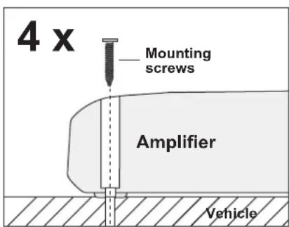
Then uphold the amplifier to the chosen position and fix the screws through the holes of the mounting brackets into the drilled screwholes.
Ensure that the mounted amplifier is fixed tight and not get loosen.
ELECTRICAL INTERCONNECTION

BEFORE THE CONNECTION
For the professional installation of a sound system appropriate wiring kits are available in car audio retailer stores. Attend the sufficient profile section (at least 10 mm²), the suitable fuse rating and the conductivity of the cables when you purchase your wiring kit. Clean and remove rust-streaked and oxidized areas on the contact points of the battery and the ground connection. Make sure that all screws are fixed tight after the installation, because loosely connections may cause malfunctions, insufficient power supply or interferences. We recommend therefore the CRUNCH CR10WK wirekit.

GND
Connect the GROUND terminal with a suitable contact ground point on the vehicle's chassis. The ground wire must be as short as possible and must be connected to a blank metallic point at the vehicle's chassis. Ensure that this ground point has a stable and safe electrical connection to the negative “-”pole of the battery. Check this ground wire from the battery to the ground point if possible and enforce it, if required. Use a ground wire with a sufficient cross section (at least 10 mm2) and the same size like the plus (+12V) power supply wire.

REM (TURN-ON SIGNAL)
Connect the turn-on signal (e.g. automatic antenna) or the turn-on remote signal of your headunit with the REM-terminal of the amplifier. Use therefor a suitable cable with a sufficient cross section (0,5 mm ^2 ). Thereby the amplifier will turn on or off automatically with your headunit.

BATT+12V
Connect the BATT+12V-terminal with the +12V pole of the vehicle's battery. Use therefor a suitable cable with a sufficient cross section (min. 10 mm ^2 ) and install a additional in-line fuse. For safety reasons the distance between the fuseblock and the battery must be shorter than 30 cm. Do not install the fuse into the fuseblock until the installation is accomplished.

FUSE
The inserted fuses protect the amplifier from shorts and capacity overload. The equipped standard fuse is suitable for a 4 ohm speaker load. For a 2 ohm speaker load the current consumption increases by 50% , thereby the fuses may need to be replaced by fuses with a higher rating.

REFERENCE NOTE
Installation of RCA/Audio signal cables and power supply.
Observe while installation not to lead the audio cables between the headunit and the amplifier together with the power supply wires on the same side of the vehicle. The best is a areal separated installation in the left and right cable channel of the vehicle. Therewith a overlap of interferences on the audio signal will be avoided. This stands also for the equipped bass-remote wire, which should be installed not together with the power supply wires, but rather with the audio signal cables.
FUNCTIONS AND OPERATIONAL CONTROLS

1
The BASS BOOST controller adjusts the bass boost enhancement continuously from 0dB to +12dB at 45 Hz.
2
The LOW PASS controller adjusts the cut-off point of the frequency range to above. The cut-off frequency is continuously adjustable from 30 Hz to 250 Hz.
3
The X-OVER switch selects the required operation mode of the amplifier.
Position LP/BP: Lowpass mode (the higher frequencies will be eliminated. Adjustable by the LOW PASS controller.) The HIGH PASS controller works in this operation mode as subsonicfilter and eliminates the lower frequencies (Bandpass-Mode). NOTE: If this controller is turned to a higher value than the lowpass controller, no sound is hearable.
Position HP: Highpass mode (the higher frequencies will be eliminate. Adjustable by the HIGH PASS controller.)
Position FULL: Fullrange mode (the entire frequency range will be amplified).
4
The HIGH PASS controller adjusts the cut-off point of the frequency range to below. The cut-off frequency is continuously adjustable from 10 Hz to 250 Hz.
The HIGH PASS controller works in the LP/BP mode as subsonicfilter and eliminates the lower frequencies (Bandpass-Mode). NOTE: If this controller is turned to a higher value than the lowpass controller, no sound is hearable.
5
The INPUT LEVEL controller adjusts the input sensitivity of the amplifier to align the audio signal from the head unit. The input sensitivity is adjustable from 6 to 0.2 Volts.
6
The MODE switch enables in switch position MONO, that only one RCA jack with a mono audio signal needs to be connected on LINE INPUT CH L. Chose this mode only, if you want to run the amplifier with a subwoofer in the LOW PASS mode.
7
The LINE INPUT RCA jacks must be connected with the RCA output jacks of the headunit. All 2 LINE INPUTS must be connected.
8
The LINE OUT RCA jacks provide summed mono audiosignal to supply an additional mono amplifier.
INTERCONNECTION EXAMPLE 2-Channel Mode: 1x Stereo System (Front or rear)

INTERCONNECTION
- Connect the RCA lineouts of the headunit with the RCA jacks LINE INPUT of the amplifier with appropriate high-value RCA cables.
- Connect the front- or rear speakers with the speaker outputs (SPEAKER OUTPUT + 1CH - and + 2CH -) by using appropriate wires.
- Ensure by any means, that the total impedance load of all speakers is not lower than 2 ohms. Too low impedance cause high temperature and will shut down the amplifier operation.
• Always ensure the correct polarity of the speakers. The interchange of plus and minus cause total loss of bass playback and could damage the speakers.
CROSSOVER SETTINGS
- For bigger speakers (more than 20cm) you can set the X-OVER switch to the FULL position (Full Range Signal).
- For smaller speakers (8.7cm - 16cm) you must set the X-OVER switch to the HP Position (Highpass Mode) to avoid any damage by lower frequencies on the speakers. The cut-off frequency is adjustable with the HIGH PASS controller and should be set between 60Hz to 150Hz, depending on the size of the speakers.
- The LOW PASS Controller is not in use in this interconnecting example.
- Turn the INPUT LEVEL controller of the amplifier to the 6V position.
- Turn the volume controller of the headunit to 80 - 90% of its full setting.
- Turn the INPUT LEVEL controller clockwise until you hear some distortion.
- Then turn back the INPUT LEVEL controller slightly until you hear a cleaner sound.
BASS BOOST CONTROLLER
- The BASS BOOST controller must be turned to 0 dB position in this interconnecting example.

REFERENCE NOTE
Do not connect loudspeaker cables with the vehicle chassis. Always ensure the correct polarity of all connections. The interchange of plus and minus cause total loss of bass playback and could damage the speakers.
INTERCONNECTION EXAMPLE 1-Channel Mode: 1x Mono Subwoofer bridged

INTERCONNECTION
- Connect the RCA lineout of the headunit with the RCA jack LINE INPUT CH L of the amplifier with an appropriate high-value RCA cable. If your headunit is equipped with a additional subwoofer lineout (SUB OUT), it is recommended to use this lineout.
- Connect the subwoofer with the speaker outputs (SPEAKER OUTPUT + BRIDGED -) by using appropriate wires.
- Ensure by any means, that the total impedance load of the channel-pair is not lower than 4 ohms. Too low impedance cause high temperature and will shut down the amplifier operation.
• Always ensure the correct polarity of the speakers. The interchange of plus and minus cause total loss of bass playback and could damage the speakers.
CROSSOVER SETTINGS
- In the mono/subwoofer mode the X-OVER switch must set to the LP/BP position (Lowpass/Bandpass mode), thereby the higher frequencies will be eliminated. The cut-off frequency is adjustable with the LOW PASS controller and should be set between 60 to 100 Hz, depending on the size of the subwoofer.
- In the lowpass mode (LP/BP) the HIGH PASS controller works also as subsonicfilter, that eliminates the ultra-low, not hearable and harmful frequencies to generate a bandpass signal (Bandpass mode). The subsonic frequency should be set between 15 to 40Hz , depending on the size of the subwoofer. NOTE: If this value is higher than the lowpass setting, no sound is hearable.
LEVEL CONTROLLER
- Turn the INPUT LEVEL controller of the amplifier to the 6V position.
- Turn the volume controller of the headunit to 80 - 90% of its full setting.
- Turn the INPUT LEVEL controller clockwise until you hear some distortion.
- Then turn back the INPUT LEVEL controller slightly until you hear a cleaner sound.
BASS BOOST CONTROLLER
- The BASS BOOST controller adjusts the bass enhancement between 0db and +12dB.
- A too high bass boost may cause clipping/distortion and damage on the loudspeakers and also may harm your hearing abilities. Use this controller carefully!

REFERENCE NOTE
Do not connect loudspeaker cables with the vehicle chassis. Always ensure the correct polarity of all connections.
Use the bass enhancement with care. A high bass boost may cause damage to your speakers and hearing abilities.
FUNCTIONS AND OPERATIONAL CONTROLS

1 The BASS BOOST CH1/2 and CH3/4 controllers adjust the bass boost enhancement continuously from 0dB to +12dB at 45 Hz for the regarding channel pair (Channel 1/2 or Channel 3/4).
2 The LOW PASS CH1/2 and CH3/4 controllers adjust the cut-off point of the frequency range to above for the regarding channel pair (Channel 1/2 or Channel 3/4). The cut-off frequency is continuously adjustable from 30 Hz to 150 Hz.
3 The CH1/2 and CH3/4 X-OVER switch selects the required operation mode of the amplifier on the regarding channel pair (Channel 1/2 or Channel 3/4).
Position LP/BP: Lowpass mode (The higher frequencies will be eliminated. Adjustable by the lowpass controller.) The HIGH PASS controller works in this operation mode as subsonicfilter and eliminates the lower frequencies (Bandpass-Mode). NOTE: If this controller is turned to a higher value than the lowpass controller, no sound is hearable.
Position HP: Highpass mode (The higher frequencies will be eliminated. Adjustable by the highpass controller.)
Position FULL: Fullrange mode (The whole frequencies will be amplified).
4 The HIGH PASS CH1/2 and CH3/4 controllers adjust the cut-off point of the frequency range to below for the regarding channel pair (Channel 1/2 or Channel 3/4). The cut-off frequency is continuously adjustable from 10 Hz to 150 Hz.
The HIGH PASS controller works in the LP/BP mode as subsonicfilter and eliminates the lower frequencies (Bandpass-Mode). NOTE: If this controller is turned to a higher value than the lowpass controller, no sound is hearable.
5 The LEVEL INPUT CH1/2 and CH3/4 controllers adjust the input sensitivity of the amplifier to align the audio signal of the head unit for the regarding channel pair (Channel 1/2 or Channel 3/4). The input sensitivity is adjustable from 6 to 0.2 Volts.
6 The LINE INPUT RCA jacks must be connected with the RCA output jacks of the headunit. All 4 LINE INPUTS must be connected. If there is only one stereo signal with two jacks available, you must use two Y-connectors to splice the signal.
7 The LINE OUT RCA jacks provide a linear fullrange audiosignal to supply an additional amplifier.
INTERCONNECTION EXAMPLE 4-Channel Mode: 2 x Stereo System (Front & Rear)

INTERCONNECTION
- Connect the RCA lineouts of the headunit with the RCA jacks LINE INPUT of the amplifier with appropriate high-value RCA cables.
- If there is only one stereo signal with two jacks available, you must use two y-connectors to splice the signal.
- Connect the front- and rear speakers with the speaker outputs (SPEAKER OUTPUT + 1CH -, + 2CH - and + 3CH -, + 4CH -).
- Ensure by any means, that the total impedance load of all speakers is not lower than 2 ohms per channel. Too low impedance cause high temperature and will shut down the amplifier operation.
• Always ensure the correct polarity of the speakers. The interchange of plus and minus cause total loss of bass playback and could damage the speakers.
CROSSOVER SETTINGS CH1/2 & CH3/4
- For bigger speakers (more than 20cm) you can set the X-OVER switch to the FULL position (Full Range Signal).
- For smaller speakers (8.7cm - 16cm) you must set the X-OVER switch to the HP Position (Highpass Mode) to avoid any damage by lower frequencies on the speakers. The cut-off frequency is adjustable with the HIGH PASS controller and should be set between 60Hz to 150Hz, depending on the size of the speakers.
- The LOW PASS Controller is not in use in this interconnecting example.
- Turn the INPUT LEVEL controller of the amplifier to the 6V position.
- Turn the volume controller of the headunit to 80 - 90% of its full setting.
- Turn the INPUT LEVEL controller clockwise until you hear some distortion.
- Then turn back the INPUT LEVEL controller slightly until you hear a cleaner sound.
BASS BOOST CONTROLLER
- The BASS BOOST controller must be turned to 0 dB position in this interconnecting example.

REFERENCE NOTE
Do not connect loudspeaker cables with the vehicle's chassis. Always ensure the correct polarity of all connections. The interchange of plus and minus cause total loss of bass playback and could damage the speakers.
INTERCONNECTION EXAMPLE 2-Channel Mode: 2 x Mono Subwoofer bridged
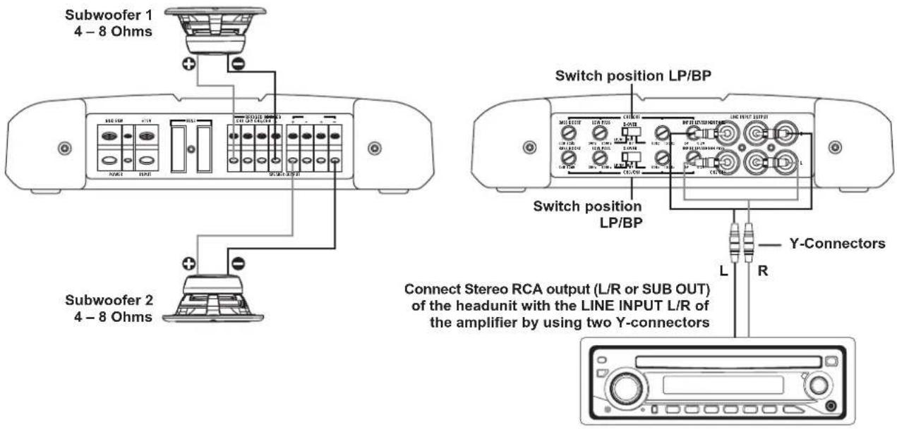
INTERCONNECTION
- Connect the RCA lineouts of the headunit with the RCA jacks LINE INPUT. All LINE INPUT jacks must be connected (CH1/CH2/CH3/CH4). Therefore you need to use two Y-connectors to splice the audio signal. If a separate SUB OUT from your headunit is available, use this as LINE OUT.
- Connect the subwoofers with the SPEAKER OUTPUTS CH1/2 + BRIDGED - and CH3/4 + BRIDGED -.
- Ensure by any means, that the total impedance load of all subwoofers per channelpair is not lower than 4 ohms. Too low impedance cause high temperature and will shut down the amplifier operation.
• Always ensure the correct polarity of the speakers. The interchange of plus and minus cause total loss of bass playback and could damage the speakers.
CROSSOVER SETTINGS CH1/2 & CH3/4 (SUBWOOFER 1 & SUBWOOFER 2)
- In the mono/subwoofer mode the X-OVER switch must set to the LP/BP position (Lowpass/Bandpass mode), thereby the higher frequencies will be eliminated. The cut-off frequency is adjustable with the LOW PASS controller and should be set between 60 to 100 Hz, depending on the size of the subwoofer.
- In the lowpass mode (LP/BP) the HIGH PASS controller works also as subsonicfilter, that eliminates the ultra-low, not hearable and harmful frequencies to generate a bandpass signal (Bandpass mode). The subsonic frequency should be set between 15 to 40Hz , depending on the size of the subwoofer. NOTE: If this value is higher than the lowpass setting, no sound is hearable.
LEVEL CONTROLLER CH1/2 & CH3/4 (SUBWOOFER 1 & SUBWOOFER 2)
- Turn the INPUT LEVEL controller of the amplifier to the 6V position.
- Turn the volume controller of the headunit to 80 - 90% of its full setting.
- Turn the INPUT LEVEL controller clockwise until you hear some distortion.
- Then turn back the INPUT LEVEL controller slightly until you hear a cleaner sound.
BASS BOOST CONTROLLER CH1/2 & CH3/4 (SUBWOOFER 1 & SUBWOOFER 2)
• The BASS BOOST controller adjusts the bass enhancement between 0db and +12dB.
- A too high bass boost may cause clipping/distortion and damage on the loudspeakers and also may harm your hearing abilities. Use this controller carefully!
EXAMPLE 3-Channel Mode: 1 x Stereo System & 1 x Mono Subwoofer bridged

INTERCONNECTION
- Connect the RCA lineouts of the headunit with the RCA jacks LINE INPUT of the amplifier with appropriate high-value RCA cables. If a separate SUB OUT from your headunit is available, use this for the LINE INPUT CH3/4 on the amplifier.
- Connect the speakers with SPEAKER OUTPUT + CH 1 - and + CH 2 - and the subwoofer with the SPEAKER OUTPUT CH3/4 + BRIDGED - of the amplifier.
- Ensure by any means, that the total impedance load of all speakers per channelpair (CH1 & CH2) is not lower than 2 ohms and the total impedance load of the subwoofer (CH3 & CH4) is not lower than 4 ohms. Too low impedance cause high temperature and will shut down the amplifier operation.
CROSSOVER SETTINGS CH1/2 (STEREO-SYSTEM)
- Observe the settings on page 25.
CROSSOVER SETTINGS CH3/4 (SUBWOOFER)
- Observe the settings on page 26.
LEVEL CONTROLLER CH1/2 & CH3/4 (STEREO SYSTEM & SUBWOOFER)
- Turn the INPUT LEVEL controller of the amplifier to the 6V position.
- Turn the volume controller of the headunit to 80 - 90% of its full setting.
- Turn the INPUT LEVEL controller clockwise until you hear some distortion.
- Then turn back the INPUT LEVEL controller slightly until you hear a cleaner sound.
BASS BOOST CONTROLLER CH1/2 (STEREO-SYSTEM)
- The BASS BOOST controller must be turned to 0 dB position in this interconnecting example.
BASS BOOST CONTROLLER CH3/4 (SUBWOOFER)
• The BASS BOOST controller adjusts the bass enhancement between 0db and +12dB.
- A too high bass boost may cause clipping/distortion and damage on the loudspeakers and also may harm your hearing abilities. Use this controller carefully!
NOTES
| MODELS | DSX2350 | DSX4500 |
| CHANNELS | 2 | 4 |
| CIRCUIT | CLASS A/BAnalog | CLASS A/BAnalog |
| OUTPUTPOWER RMS 13,8 V | ||
| Watts @ 4 Ohms | 2 x 100 | 4 x 75 |
| Watts @ 2 Ohms | 2 x 175 | 4 x 125 |
| Watts @ 4 Ohm mono bridged | 1 x 350 | 2 x 250 |
| OUTPUTPOWER MAX. 13,8 V | ||
| Watts @ 4 Ohms | 2 x 200 | 4 x 150 |
| Watts @ 2 Ohms | 2 x 350 | 4 x 250 |
| Watts @ 4 Ohm mono bridged | 1 x 700 | 2 x 500 |
| Frequency Range -3dB | 10Hz - 50 kHz | 10Hz - 50 kHz |
| Damping Factor | >300 | >200 |
| Signal-to-Noise Ratio | >104 dB | >104 dB |
| Channel Separation | 74 dB | 74 dB |
| THD&N | <0,05% | <0,05% |
| Input Sensitivity | 6 - 0.2 V | 6 - 0.2 V |
| Input Impedance | 47 kOhms | 47 kOhms |
| Speaker Impedance | 2 - 16 Ohms | 2 - 16 Ohms |
| CH 1 & CH 2 | ||
| X-Over Modes | LP/BP - HP - Full | LP/BP - HP - Full |
| Various Highpassfilter | 15 - 250 Hz | 10 - 150 Hz |
| Various Lowpassfilter | 30 - 250 Hz | 30 - 150 Hz |
| Bass Boost @ 45 Hz | 0 - 12 dB | 0 - 12 dB |
| CH 3 & CH 4 | ||
| X-Over Modes | - | LP/BP - HP - Full |
| Various Highpassfilter | - | 10 - 150 Hz |
| Various Lowpassfilter | - | 30 - 150 Hz |
| Bass Boost @ 45 Hz | - | 0 - 12 dB |
| Cinch/RCA Outputs | Fullrange | Fullrange |
| Fuse Ratings | 2 x 25 A | 2 x 30 A |
| Dimensions | ||
| Width & Height | 202 x 48 mm | 202 x 48 mm |
| Length (Length total) | 230 (270) mm | 230 (270) mm |
Technical specifications are subject to change! Errors are reserved!
For damages on the vehicle and the device, caused by handling errors of the device, we can't assume liability.
All Crunch Amplifiers are tagged with a individual serialnumber, which will be registered for statistic and service conditional purposes.
All Crunch Amplifiers are tagged with a E-Certification Number and also a CE-Certification Mark. Thereby these devices are certified for the use inside vehicles inside the European Union (EU).
WARRANTY DISCLAIMER
The limited warranty comply with legal regulations. Failures or damages caused by overload, improper use or by using the product for competitions are not covered by the warranty.
Please return the defective product only with a valid proof of purchase and a detailed malfunction description.
STATUS LED & PROTECTION CIRCUIT
The STATUS LED is located on the top side of the amplifier next to the model number.
- If the STATUS LED lights up in blue, the amplifier is turned on and is ready for operation.
- If the STATUS LED lights up in red, a malfunction occurs on the amplifier. Please observe therefor the following information in the section TROUBLE SHOOTING.
DEFINITION
DSX4500


REFERENCE NOTE
PROTECTION CIRCUIT
This amplifier owns a 3-way protection circuit. If overloading, overheating and shorted loudspeakers, or too low impedance or insufficient power supply is insisted, the amplifier shuts down to prevent serious damage. If one of this disfunctions is detected, the STATUS LED lights up red.
Check in this case all connections to detect short-circuits, faulty connections or overheating. Attend the regarding notes on the previous page.
If the reason for the disfunction is eliminated, the amplifier is ready for operation again.
If the STATUS LED does not stop to light up in red, a damage on the amplifier is insisted. In this case return the amplifier to your car audio retailer with a detailed malfunction description and a copy of the proof of purchase.
WARNING: Never open the amplifier and try to repair it by yourself. This causes a loss of warranty. The repairing service should be made only by skilled technicians.

REFERENCE NOTE
ELECTRICAL INTERFERENCES
The reason for interferences are mostly the passed cables and wires. Especially the power and audio cables (RCA) of your sound system are vulnerable. Often these interferences are caused by electric generators or other electrical units (fuel pump, AC etc.) of the car. The most of these problems can be prevented by a correct and careful wiring.
Here are some courtesy notes:
- Use only double or triple shielded audio RCA cables for the connection between the amplifier and headunit. A useful alternative are represented by anti-noise-devices or additional ancillary equipment like Balanced Line Transmitters, which you can purchase at your car audio retailer. If possible do not use anti-noise-filters, which are splicing the ground of the RCA audio cables.
- Do not lead the audio cables between the headunit and the amplifier together with the power supply wires on the same side of the vehicle. The best is a areal separated installation in the left and right cable channel of the vehicle. Therewith a overlap of interferences on the audio signal will be avoided. This stands also for the equipped bass-remote wire, which should be installed not together with the power supply wires, but rather with the audio signal cables.
- Avoid ground loops by connecting all ground connections in a starlike arrangement. The suitable ground center point is ascertainable by measuring of the voltage directly on the vehicle's battery by a multi-meter. You should measure the voltage with turned-on inginition (acc.) and with other turned-on power consumers (e.g. headlights, rear window defroster, etc). Compare the measured value with the voltage of the ground point you have chosen for the installation and the positive pole (+12V) of the amplifier. If the voltage has just a little difference, you have found a suitable ground point. Otherwise you need to choose another ground point.
- Use if possible only cables with added or soldered cable sockets or the like. Gold plated or high value nickel plated cable sockets are corrosionfree and own a very low contact resistance.
Malfunction: no function
Reason: Remedy:
- The power supply connection of the device is not correct. Recheck
- The cables have no mechanical or electrical contact. Recheck
- The remote turn-on connection from the headunit to the amplifier is not correct. Recheck
- Defective Fuses. In case of replacing the fuses, attend by any means the correct fuse rating. Replace Fuses
Malfunction: no signal on loudspeakers, but STATUS LED lights up blue
Reason: Remedy:
- The connection of the speakers or the RCA audio cables is not correct.. Recheck
- The speaker cables or the RCA audio cables are defective. Replace cables
- The loudspeakers are defective. Replace speakers
- High pass controller (Subsonic Mode) in LP/BP operation is adjusted to high. Turn down controller
- No signal from headunit. Check headunit settings
Malfunction: one or more channels/controllers are without function / faulty stereo stage
Reason: Remedy:
- The balance or fader controller of the headunit is not in the zero-position. Turn to zero-position
- The connection of the speakers is not correct. Recheck
- The loudspeakers are defective. Replace speakers
- High pass controller in LP/BP operation is adjusted to high. Turn down controller
Malfunction: distortions on the loudspeaker's signal
Reason: Remedy:
- The loudspeakers are overloaded. Turn down the level
Turn down the level on the headunit Switch off loudness on the headunit Reset bass EQ on the headunit
Malfunction: No bass or stereo sound
Reason: Remedy:
- Interchange of loudspeaker cable polarity positive (+) and negative (-). Reconnect
- The RCA audio cables are loose or defective.
Reconnect or replacing the cables
Malfunction: amplifier runs into protection mode (STATUS LED lights up red)
Reason: Remedy:
- Short circuit on the loudspeakers or cables.
- Overheated by too low speaker impedance.
- Insufficient air circulation by a inappropriate mounting position of the amplifier.
- Overloaded by insufficient power supply (too thin profile section on the power cables).
Reconnect
Choose a higher impedance Use a new speaker setup
Change the mounting position Ensure air circulation
Use a bigger profile section
Malfunction: hiss or white noise on the loudspeaker's signal
Reason: Remedy:
- The level controllers are turned up. Turn down the level
- The treble controller on the headunit is turned up.
- The speaker cables or the RCA audio cables are defective. Replacing the cables
- The hissing is caused by the headunit.
Turn down the level on the headunit
Check the headunit
CAR AUDIO UNLIMITED
CRUNCH
turn up your life

Audio Design GmbH · www.audiodesign.de
Am Breilingsweg 3 · D-76709 Kronau (Germany) Tel. +49 (0)7253 - 9465-0 · Fax +49 (0)7253 - 946510

- SAFETY INSTRUCTIONS 18
- INSTALLATION INSTRUCTIONS 19
- 2-CHANNEL AMPLIFIERS 21
- 4-CHANNEL AMPLIFIERS 24
- SPECIFICATIONS 29
- TROUBLE SHOOTING 30
- REFERENCE NOTE!
- VERY IMPORTANT ADVICE FOR THE INSTALLATION AND OPERATION IN NEWER VEHICLES!
- PLEASE OBSERVE THE FOLLOWING ADVICES BEFORE THE FIRST OPERATION!
- REFERENCE NOTE
- MECHANICAL INSTALLATION
- BEFORE THE CONNECTION
- GND
- REM (TURN-ON SIGNAL)
- BATT+12V
- FUSE
- Installation of RCA/Audio signal cables and power supply.
- INTERCONNECTION
- CROSSOVER SETTINGS
- BASS BOOST CONTROLLER
- LEVEL CONTROLLER
- CROSSOVER SETTINGS CH1/2 & CH3/4
- CROSSOVER SETTINGS CH1/2 & CH3/4 (SUBWOOFER 1 & SUBWOOFER 2)
- LEVEL CONTROLLER CH1/2 & CH3/4 (SUBWOOFER 1 & SUBWOOFER 2)
- BASS BOOST CONTROLLER CH1/2 & CH3/4 (SUBWOOFER 1 & SUBWOOFER 2)
- CROSSOVER SETTINGS CH1/2 (STEREO-SYSTEM)
- CROSSOVER SETTINGS CH3/4 (SUBWOOFER)
- LEVEL CONTROLLER CH1/2 & CH3/4 (STEREO SYSTEM & SUBWOOFER)
- BASS BOOST CONTROLLER CH1/2 (STEREO-SYSTEM)
- BASS BOOST CONTROLLER CH3/4 (SUBWOOFER)
- NOTES
- WARRANTY DISCLAIMER
- STATUS LED & PROTECTION CIRCUIT
- PROTECTION CIRCUIT
- ELECTRICAL INTERFERENCES
- Here are some courtesy notes:
- Malfunction: no function
- Reason: Remedy:
- Malfunction: no signal on loudspeakers, but STATUS LED lights up blue
- Malfunction: one or more channels/controllers are without function / faulty stereo stage
- Malfunction: distortions on the loudspeaker's signal
- Malfunction: No bass or stereo sound
- Malfunction: amplifier runs into protection mode (STATUS LED lights up red)
- Malfunction: hiss or white noise on the loudspeaker's signal
- CRUNCH
Brand : Crunch
Model : DSX4500
Category : Car radio