
SUN2000MA-3KTL-M1 - Uncategorized HUAWEI - Free user manual and instructions
Find the device manual for free SUN2000MA-3KTL-M1 HUAWEI in PDF.

| Product Type | Three-phase grid-tied PV string inverter |
| Model | SUN2000-3KTL-M1 |
| Dimensions (W x H x D) | 525 x 470 x 166 mm |
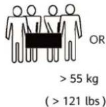
| Weight | 17 kg |
| Maximum DC Input Voltage | 1100 V |
| MPPT Voltage Range | 140 - 980 V DC |
| Nominal AC Output Power | 3 kW |
| Nominal AC Voltage | 220/380 V AC or 230/400 V AC |
| AC Frequency | 50/60 Hz |
| Inverter Topology | Transformerless |
| IP Rating | IP65 |
| Protection Class | I |
| Operating Temperature | -25°C to +60°C (derated above 45°C) |
| Cooling | Natural convection |
| Noise Emission | 29 dB(A) typical |
| Maximum Operating Altitude | 4000 m (derated above 3000 m) |
| Communication Interfaces | RS485, WLAN, optional 4G or WLAN-FE dongle |
| Arc Fault Protection (AFCI) | Type I |
| Earth Leakage Protection | Integrated residual current monitoring (RCMU) |
| Supported Power Grid Types | TN-S, TN-C, TN-C-S, TT, IT |
Frequently Asked Questions - SUN2000MA-3KTL-M1 HUAWEI
User questions about SUN2000MA-3KTL-M1 HUAWEI
0 question about this device. Answer the ones you know or ask your own.
Ask a new question about this device
Download the instructions for your Uncategorized in PDF format for free! Find your manual SUN2000MA-3KTL-M1 - HUAWEI and take your electronic device back in hand. On this page are published all the documents necessary for the use of your device. SUN2000MA-3KTL-M1 by HUAWEI.
USER MANUAL SUN2000MA-3KTL-M1 HUAWEI
natural_image
Abstract red line drawing of a stylized human figure with flowing lines (no text or symbols)Copyright © Huawei Technologies Co., Ltd. 2022. All rights reserved.
No part of this document may be reproduced or transmitted in any form or by any means without prior written consent of Huawei Technologies Co., Ltd.
Trademarks and Permissions

HUAWEI and other Huawei trademarks are trademarks of Huawei Technologies Co., Ltd.
All other trademarks and trade names mentioned in this document are the property of their respective holders.
Notice
The purchased products, services and features are stipulated by the contract made between Huawei and the customer. All or part of the products, services and features described in this document may not be within the purchase scope or the usage scope. Unless otherwise specified in the contract, all statements, information, and recommendations in this document are provided "AS IS" without warranties, guarantees or representations of any kind, either express or implied.
The information in this document is subject to change without notice. Every effort has been made in the preparation of this document to ensure accuracy of the contents, but all statements, information, and recommendations in this document do not constitute a warranty of any kind, express or implied.
Huawei Technologies Co., Ltd.
Address: Huawei Industrial Base
Bantian, Longgang
Shenzhen 518129
People's Republic of China
Website: https://e.huawei.com
About This Document
Overview
This document describes the SUN2000-3KTL-M1, SUN2000-4KTL-M1, SUN2000-5KTL-M1, SUN2000-6KTL-M1, SUN2000-8KTL-M1, and SUN2000-10KTL-M1 (SUN2000 for short) in terms of their installation, electrical connections, commissioning, maintenance, and troubleshooting. Before installing and operating the SUN2000, ensure that you are familiar with the features, functions, and safety precautions provided in this document.
Intended Audience
This document is applicable to:
- Installers
- Users
Symbol Conventions
The symbols that may be found in this document are defined as follows:
| Symbol | Description |
 | Indicates a hazard with a high level of risk which, if not avoided, will result in death or serious injury. |
 | Indicates a hazard with a medium level of risk which, if not avoided, could result in death or serious injury. |
 | Indicates a hazard with a low level of risk which, if not avoided, could result in minor or moderate injury. |
 | Indicates a potentially hazardous situation which, if not avoided, could result in equipment damage, data loss, performance deterioration, or unanticipated results.Notice is used to address practices not related to personal injury. |
| Symbol Description | |
| NOTE | Supplements the important information in the main text.NOTE is used to address information not related to personal injury, equipment damage, and environment deterioration. |
Change History
Changes between document issues are cumulative. The latest document issue contains all the changes made in earlier issues.
Issue 05 (2022-03-10)
- Updated About This Document.
- Updated A Grid Code.
- Updated C Setting Power Adjustment Parameters.
Issue 04 (2021-08-10)
- Updated 2.1 Product Introduction.
- Updated 5.4 Installing DC input power cables.
- Updated 5.5 (Optional) Connecting Battery Cables.
- Updated 5.7 (Optional) Connecting the Signal Cable.
- Updated 7 Man-Machine Interaction.
- Updated B Device Commissioning.
Issue 03 (2021-02-01)
- Updated 4.3.2 Space Requirements.
- Updated 5.7.2 Connecting the RS485 Communications Cable (Smart Power Sensor).
- Updated 6.2 SUN2000 power-on.
- Updated 8.3 Troubleshooting.
Issue 02 (2020-11-20)
Updated 7.2.1.2 Battery Control.
Issue 01 (2020-09-30)
This issue is used for first office application (FOA).
Contents
About This Document......ii
1 Safety Information.... 1
1.1 General Safety.... 1
1.2 Personnel Requirements.... 2
1.3 Electrical Safety....3
1.4 Installation Environment Requirements....4
1.5 Mechanical Safety....4
1.6 Commissioning....6
1.7 Maintenance and Replacement....6
2 Overview....7
2.1 Product Introduction....7
2.2 Appearance.... 10
2.3 Label Description.... 12
2.3.1 Enclosure Labels....12
2.3.2 Product Nameplate....14
2.4 Working Principles....14
2.4.1 Circuit Diagram.... 14
2.4.2 Working Modes....15
3 Storage....17
4 Installation....18
4.1 Checking Before Installation.... 18
4.2 Tools....19
4.3 Determining the Installation Position....20
4.3.1 Environment Requirements....20
4.3.2 Space Requirements.... 21
4.4 Moving the SUN2000.... 24
4.5 Installing the Mounting Bracket....24
4.5.1 Wall-mounted Installation....25
4.5.2 Support-mounted Installation....27
5 Electrical Connections.... 31
5.1 Installation Preparation.... 31
5.2 Connecting the PE cable....34
5.3 Connecting the AC Output Power Cable.... 36
5.4 Installing DC input power cables....40
5.5 (Optional) Connecting Battery Cables.... 44
5.6 Install the Smart Dongle.... 46
5.7 (Optional) Connecting the Signal Cable....48
5.7.1 Connecting the RS485 Communications Cable (Inverter Cascading).... 52
5.7.2 Connecting the RS485 Communications Cable (Smart Power Sensor)....53
5.7.3 Connecting an RS485 Communications Cable (Between a Power Meter and a Battery)....57
5.7.4 Connecting the Power Grid Scheduling Signal Cable.... 58
5.7.5 Connecting a Signal Cable to the Smart Backup Box....59
5.7.6 Connecting the NS Protection Signal Cable....60
6 Commissioning....63
6.1 Checking Before Power-On....63
6.2 SUN2000 power-on....64
7 Man-Machine Interaction....70
7.1 App Commissioning.... 70
7.1.1 Downloading the FusionSolar App....70
7.1.2 (Optional) Registering an Installer Account....71
7.1.3 Creating a PV Plant and a User....72
7.1.4 (Optional) Setting the Physical Layout of the Smart PV Optimizers....72
7.1.5 Detect optimizer disconnection....74
7.2 Parameters Settings.... 75
7.2.1 Energy Control....75
7.2.1.1 Grid-tied Point Control....76
7.2.1.2 Battery Control....79
7.2.2 AFCI....81
7.2.3 IPS Check (for Italy CE10-21 Grid Code Only) 82
7.3 SmartLogger Networking Scenario.... 84
8 Maintenance....85
8.1 SUN2000 Power-Off 85
8.2 Routine Maintenance.... 86
8.3 Troubleshooting....86
9 Handling the Inverter....98
9.1 Removing the SUN2000.... 98
9.2 Packing the SUN2000....98
9.3 Disposing of the SUN2000.... 98
10 Technical Specifications....99
10.1 SUN2000 Technical Specifications....99
10.2 Optimizer Technical Specifications....104
A Grid Code.... 107
B Device Commissioning....109
C Setting Power Adjustment Parameters.... 112
D Resetting Password.... 114
E Rapid Shutdown.... 117
F Locating Insulation Resistance Faults.... 118
G DRM Configuration Guide for Standard As NZS4777.2.... 121
H Acronyms and Abbreviations....122
1 Safety Information
1.1 General Safety
Statement
Before installing, operating, and maintaining the equipment, read this document and observe all the safety instructions on the equipment and in this document.
The "NOTICE", "CAUTION", "WARNING", and "DANGER" statements in this document do not cover all the safety instructions. They are only supplements to the safety instructions. Huawei will not be liable for any consequence caused by the violation of general safety requirements or design, production, and usage safety standards.
Ensure that the equipment is used in environments that meet its design specifications. Otherwise, the equipment may become faulty, and the resulting equipment malfunction, component damage, personal injuries, or property damage are not covered under the warranty.
Follow local laws and regulations when installing, operating, or maintaining the equipment. The safety instructions in this document are only supplements to local laws and regulations.
Huawei will not be liable for any consequences of the following circumstances:
- Operation beyond the conditions specified in this document
- Installation or use in environments which are not specified in relevant international or national standards
- Unauthorized modifications to the product or software code or removal of the product
- Failure to follow the operation instructions and safety precautions on the product and in this document
- Equipment damage due to force majeure, such as earthquakes, fire, and storms
- Damage caused during transportation by the customer
- Storage conditions that do not meet the requirements specified in this document
General Requirements
D ANGER
Do not work with power on during installation.
- Do not install, use, or operate outdoor equipment and cables (including but not limited to moving equipment, operating equipment and cables, inserting connectors to or removing connectors from signal ports connected to outdoor facilities, working at heights, and performing outdoor installation) in harsh weather conditions such as lightning, rain, snow, and level 6 or stronger wind.
- After installing the equipment, remove idle packing materials such as cartons, foam, plastics, and cable ties from the equipment area.
- In the case of a fire, immediately leave the building or the equipment area, and turn on the fire alarm bell or make an emergency call. Do not enter the building on fire in any case.
- Do not scrawl, damage, or block any warning label on the equipment.
- Tighten the screws to the specified torque using tools when installing the equipment.
- Understand the components and functioning of a grid-tied PV power system and relevant local standards.
- Repaint any paint scratches caused during equipment transportation or installation in a timely manner. Equipment with scratches cannot be exposed to an outdoor environment for a long period of time.
- Do not open the host panel of the equipment.
- You shall not reverse engineer, decompile, disassemble, adapt, add code to the device software or alter the device software in any other way, research the internal implementation of the device, obtain the device software source code, infringe on Huawei's intellectual property, or disclose any device software performance test results.
Personal Safety
- If there is a probability of personal injury or equipment damage during operations on the equipment, immediately stop the operations, report the case to the supervisor, and take feasible protective measures.
- Use tools correctly to avoid hurting people or damaging the equipment.
- Do not touch the energized equipment, as the enclosure is hot.
1.2 Personnel Requirements
- Personnel who plan to install or maintain Huawei equipment must receive thorough training, understand all necessary safety precautions, and be able to correctly perform all operations.
- Only qualified professionals or trained personnel are allowed to install, operate, and maintain the equipment.
-
Only qualified professionals are allowed to remove safety facilities and inspect the equipment.
-
Personnel who will operate the equipment, including operators, trained personnel, and professionals, should possess the local national required qualifications in special operations such as high-voltage operations, working at heights, and operations of special equipment.
- Only professionals or authorized personnel are allowed to replace the equipment or components (including software).
NO TE
- Professionals: personnel who are trained or experienced in equipment operations and are clear of the sources and degree of various potential hazards in equipment installation, operation, and maintenance
- Trained personnel: personnel who are technically trained, have required experience, are aware of possible hazards on themselves in certain operations, and are able to take protective measures to minimize the hazards on themselves and other people
- Operators: operation personnel who may come in contact with the equipment, except trained personnel and professionals
1.3 Electrical Safety
Grounding
- For the equipment that needs to be grounded, install the ground cable first when installing the equipment and remove the ground cable last when removing the equipment.
- Do not damage the ground conductor.
- Do not operate the equipment in the absence of a properly installed ground conductor.
- Ensure that the equipment is connected permanently to the protective ground. Before operating the equipment, check its electrical connection to ensure that it is securely grounded.
General Requirements
D ANGER
Before connecting cables, ensure that the equipment is intact. Otherwise, electric shocks or fire may occur.
- Ensure that all electrical connections comply with local electrical standards.
- Obtain approval from the local electric utility company before using the equipment in grid-tied mode.
- Ensure that the cables you prepared meet local regulations.
- Use dedicated insulated tools when performing high-voltage operations.
AC and DC Power
D ANGER
Do not connect or disconnect power cables with power on. Transient contact between the core of the power cable and the conductor will generate electric arcs or sparks, which may cause fire or personal injury.
- Before making electrical connections, switch off the disconnector on the upstream device to cut off the power supply if people may contact energized components.
- Before connecting a power cable, check that the label on the power cable is correct.
- If the equipment has multiple inputs, disconnect all the inputs before operating the equipment.
Cabling
- When routing cables, ensure that a distance of at least 30 mm exists between the cables and heat-generating components or areas. This prevents damage to the insulation layer of the cables.
- Bind cables of the same type together. When routing cables of different types, ensure that they are at least 30 mm away from each other.
- Ensure that the cables used in a grid-tied PV power system are properly connected and insulated and meet specifications.
1.4 Installation Environment Requirements
- Ensure that the equipment is installed in a well ventilated environment.
- To prevent fire due to high temperature, ensure that the ventilation vents or heat dissipation system are not blocked when the equipment is running.
- Do not expose the equipment to flammable or explosive gas or smoke. Do not perform any operation on the equipment in such environments.
1.5 Mechanical Safety
Using Ladders
- Use wooden or fiberglass ladders when you need to perform live working at heights.
- When a step ladder is used, ensure that the pull ropes are secured and the ladder is held firm.
- Before using a ladder, check that it is intact and confirm its load bearing capacity. Do not overload it.
- Ensure that the wider end of the ladder is at the bottom, or protective measures have been taken at the bottom to prevent the ladder from sliding.
- Ensure that the ladder is securely positioned. The recommended angle for a ladder against the floor is 75 degrees, as shown in the following figure. An angle rule can be used to measure the angle.
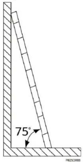
- When climbing a ladder, take the following precautions to reduce risks and ensure safety:
- Keep your body steady.
- Do not climb higher than the fourth rung of the ladder from the top.
- Ensure that your body's center of gravity does not shift outside the legs of the ladder.
Drilling Holes
When drilling holes into a wall or floor, observe the following safety precautions:
- Wear goggles and protective gloves when drilling holes.
- When drilling holes, protect the equipment from shavings. After drilling, clean up any shavings that have accumulated inside or outside the equipment.
Moving Heavy Objects
- Be cautious to avoid injury when moving heavy objects.
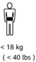
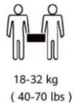
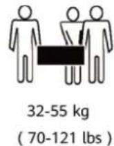

- When moving the equipment by hand, wear protective gloves to prevent injuries.
1.6 Commissioning
When the equipment is powered on for the first time, ensure that professional personnel set parameters correctly. Incorrect settings may result in inconsistency with local certification and affect the normal operation of the equipment.
1.7 Maintenance and Replacement

D ANGER
High voltage generated by the equipment during operation may cause an electric shock, which could result in death, serious injury, or serious property damage. Prior to maintenance, power off the equipment and strictly comply with the safety precautions in this document and relevant documents.
- Maintain the equipment with sufficient knowledge of this document and using proper tools and testing equipment.
- Before maintaining the equipment, power it off and follow the instructions on the delayed discharge label to ensure that the equipment is powered off.
- Turn off the AC and DC switches of the SUN2000 when maintaining the electric equipment or power distribution equipment connected the SUN2000.
- Place temporary warning signs or erect fences to prevent unauthorized access to the maintenance site.
- If the equipment is faulty, contact your dealer.
- The equipment can be powered on only after all faults are rectified. Failing to do so may escalate faults or damage the equipment.
2 Overview
2.1 Product Introduction
Functions
The SUN2000 inverter is a three-phase grid-tied PV string inverter that converts the DC power generated by PV strings into AC power and feeds the power into the power grid.
Model
This document covers the following SUN2000 models:
- SUN2000-3KTL-M1
- SUN2000-4KTL-M1
• SUN2000-5KTL-M1 - SUN2000-6KTL-M1
• SUN2000-8KTL-M1
• SUN2000-10KTL-M1
NO TE
The SUN2000-8KTL-M1 and SUN2000-10KTL-M1 are not applicable to Australia.
Figure 2-1 Model description (using SUN2000-5KTL-M1 as an example)
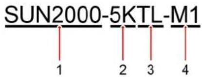
Table 2-1 Model description
| Identifier Description Value | ||
| 1 Series name | SUN2000: three-phase grid-tied PV string inverter | |
| 2 Power class | 3K: rated power of 3 kW4K: rated power of 4 kW5K: rated power of 5 kW6K: rated power of 6 kW8K: rated power of 8 kW10K: rated power of 10 kW | |
| 3 Topology T | transformerless | |
| 4 Product code | M1: product series with an input voltage level of 1100 V DC | |
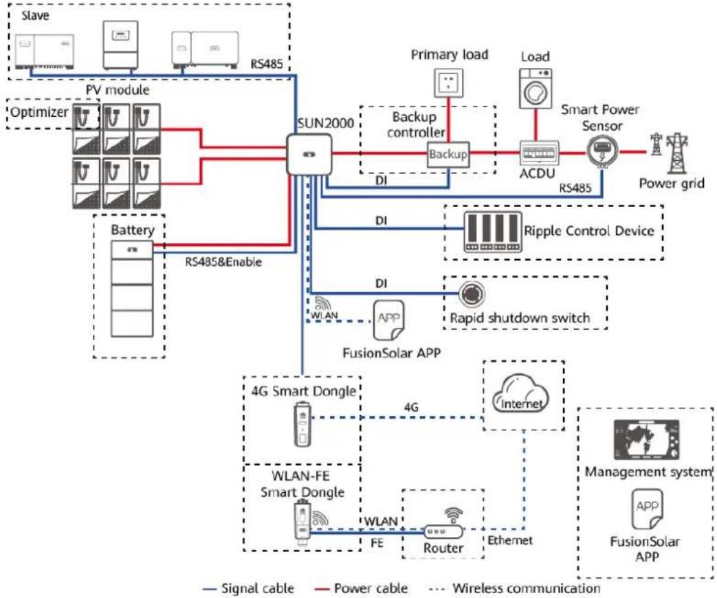
Networking Application
The SUN2000 applies to residential rooftop grid-tied systems and small-sized ground PV plant grid-tied systems. Typically, a grid-tied system consists of PV strings, grid-tied inverters, AC switches, and power distribution units.
Figure 2-2 Networking application (dashed boxes indicate optional components)
flowchart
graph TD
    subgraph "PV module"
        A["Slave"] --> B["PV module"]
        C["Optimizer"] --> D["Battery"]
        E["RS485"] --> F["SUN2000"]
        G["RS485&Enable"] --> F
        F --> H["Backup controller"]
        H --> I["DCU"]
        J["Primary load"] --> H
        K["Load"] --> L["Smart Power Sensor"]
        M["Power grid"] --> N["Power grid"]
        O["DI"] --> P["Ripple Control Device"]
        Q["DI"] --> R["Rapid shutdown switch"]
        S["DI"] --> T["FusionSolar APP"]
        U["4G Smart Dongle"] --> V["4G"]
        W["WLAN-FE Smart Dongle"] --> X["WLAN"]
        Y["FE"] --> Z["Router"]
        AA["Ethernet"] --> AB["Internet"]
        AC["Management system"] --> AD["FusionSolar APP"]
    end
    style "PV module" fill:#f9f,stroke:#333
    style "PV module" fill:#ccf,stroke:#333
    style "Battery" fill:#cfc,stroke:#333
    style "Battery" fill:#fcc,stroke:#333
    style "Power grid" fill:#ffc,stroke:#333
    style "Power grid" fill:#fcc,stroke:#333
    style "Power grid" fill:#ffc,stroke:#333
    style "Power grid" fill:#fcc,stroke:#333
    style "Power grid" fill:#ffc,stroke:#333
    style "Power grid" fill:#fcc,stroke:#333
    style "Power grid" fill:#ffc,stroke:#333
    style "Power grid" fill:#fff,stroke:#333
    style "Power grid" fill:#fff,stroke:#333
    style "Power grid" fill:#fff,stroke:#333
    style "Power grid" fill:#fff,stroke:#333
    style "Power grid" fill:#fff,stroke:#333
    style "Power grid" fill:#fff,stroke:#333
    style "Power grid" fill:#fff,stroke:#--------------|
    style "Power grid" fill:#fff,stroke:#--------------|
    style "Power grid" fill:#fff,stroke:#--------------|
    style "Power grid" fill:#fff,stroke:#--------------|
    style "Power grid" fill:#fff,stroke:#--------------|
    style "Power grid" fill:#fff,stroke:#--------------|
    style "Power grid" fill:#fff,stroke:#--------------|
    style "Power grid" fill:#fff,stroke:#--------------|
    subgraph "PV module"
        A
        B
        C
        D
        E
        F
        G
        H
        I
        J
        K
        L
        M
        N
        O
        P
        Q
        R
        S
        T
        U
        V
        W
        X
        Y
        Z
        AA
        AB
        AC
        AD
        AE
        AF
        AG
        AH
        AI
        AJ
        AK
        AL
        AM
        AN
        AO
        AP
        AQ
        AR
        AS
        AT
        AU
        AV
        AW
        AX
        AY
    end

    subgraph "Sun2000"
        F
        H
        I
        J
        K
        L
        M
        N
        O
        P
        Q
        R
        S
        T
        U
        V
        W
        X
        Y
        Z
        AA
        AB
        AC
        AD
        AE
        AF
        AG
        AH
    end

    subgraph "Signal cable"
        F1["DI"] --> F2["DI"]
    end

    subgraph "Power cable"
        F1 --> F2["DI"]
    end

    subgraph "Wireless communication"
        F1 --> F2["DI"]
    end

    subgraph "Signal cable"
        F2 --> F1a["DI"]
    end

    subgraph "Power cable"
        F2 --> F2a["DI"]
    end

    subgraph "Wireless communication"
        F2a --> F2a1["DI"]
    end

    subgraph "Signal cable"
        F2b["DI"] --> F2b1["DI"]
    end

    subgraph "Power cable"
        F2c["DI"] --> F2c1["DI"]
    end

    subgraph "Wireless communication"
        F2d["DI"] --> F2d1["DI"]
    end

    subgraph "Signal cable"
        F2e["DI"] --> F2e1["DI"]
    end

    subgraph "Power cable"
        F2f["DI"] --> F2f1["DI"]
    end

    subgraph "Wireless communication"
        F2g["DI"] --> F2g1["DI"]
    end

    subgraph "Signal cable"
        F2h["DI"] --> F2h1["DI"]
    end

    subgraph "Power cable"
        F2i["DI"] --> F2i1["DI"]
    end

    subgraph "Wireless communication"
        F2j["DI"] --> F2j1["DI"]
    end

    subgraph "Signal cable"
        F2k["DI"] --> F2k1["DI"]
    end

    subgraph "Power cable"
        F2l["DI"] --> F2l1["DI"]
    end

    subgraph "Wireless communication"
        F2m["DI"] --> F2m1["DI"]
    end

    subgraph "Signal cable"
        F2n["DI"] --> F2n1["DI"]
    end

    subgraph "Power cable"
        F2o["DI"] --> F2o1["DI"]
    end

    subgraph "Wireless communication"
        F2p["DI"] --> F2p1["DI"]
    end

    subgraph "Signal cable"
        F2q["DI"] --> F2q1["DI"]
    end

    subgraph "Power cable"
        F2r["DI"] --> F2r1["DI"]
    end

    subgraph "Wireless communication"
        F2s["DI"] --> F2s1["DI"]
    end

    subgraph "Signal cable"
        F2t["DI"] --> F2t1["DI"]
    end

    subgraph "Power cable"
        F2u["DI"] --> F2u1["DI"]
    end

    subgraph "Wireless communication"
        F2v["DI"] --> F2v1["DI"]
    end

    subgraph "Signal cable"
        F2w["DI"] --> F2w1["DI"]
    end

    subgraph "Power cable"
        F2x["DI"] --> F2x1["DI"]
    end

    subgraph "Wireless communication"
        F2y["DI"] --> F2y1["DI"]
    end

    subgraph "Signal cable"
        F2z["DI"] --> F2z1["DI"]
    end

    subgraph "Power cable"
        F2x1["DI"] --> F2x11["DI"]
    end

    subgraph "Wireless communication"
        F2y1["DI"] --> F2y11["DI"]
    end

    subgraph "Signal cable"
        F2z1["DI"] --> F2z11["DI"]
    end
NO TE
- If the built-in Wi-Fi module of the SUN2000 connects to the app, only device commissioning can be performed.
- In the SUN2000 cascading scenario, the master inverter model can be SUN2000-(3KTL-10KTL)-M1, and the slave inverter model can be SUN2000-(3KTL-10KTL)-M1, SUN2000-(8KTL-20KTL)-M2, SUN2000-(20KTL-40KTL)-M3, SUN2000-(5KTL-20KTL)-M0, SUN2000-50KTL/60KTL/65KTL-M0, SUN2000-29.9KTL/36KTL, or SUN2000-33KTL-A.
NO TE
For detailed operations on devices in the network, see the following guides:
• SUN2000-450W-P Smart PV Optimizer Quick Guide
• LUNA2000-(5-30)-S0 User Manual
- Backup Box-(B0, B1) Quick Guide
CA UTION
The off-grid load output port of the Backup Box cannot be directly connected to the power grid. Otherwise, the Backup Box will be shut down due to overload.
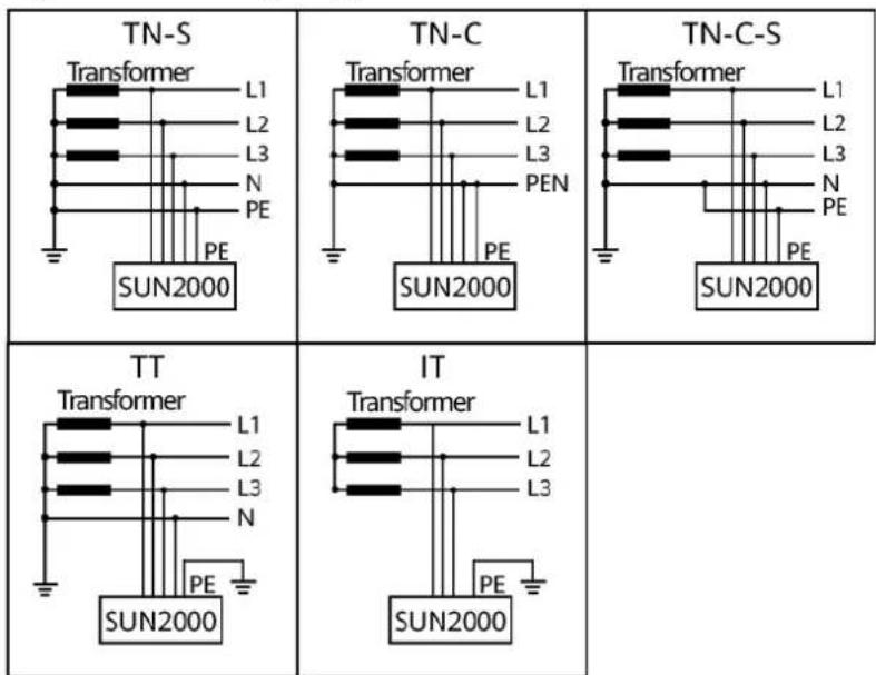
Supported Power Grid Types
The SUN2000 supports TN-S, TN-C, TN-C-S, TT, and IT power grids.
Figure 2-3 Power grid types
IS01S10001
NO TE
- When the SUN2000 is used in the TT power grid, the N-to-PE voltage must be less than 30 V.
- When the SUN2000 is used in the IT power grid, set Isolation to Input ungrounded, with TF.
2.2 Appearance
Figure 2-4 Appearance
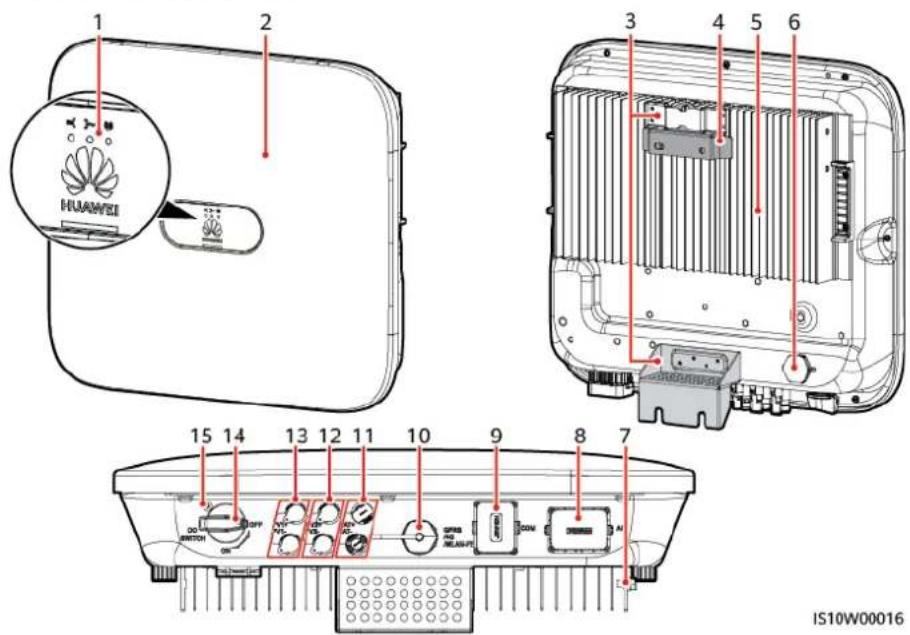
(1) LED indicator (2) Front panel
(3) Hanging kit (4) Mounting bracket
(5) Heat sink (6) Ventilation valve
(7) Ground screw (8) AC output port (AC)
(9) Communications port (COM) (10) Smart Dongle port (GPRS/4G/WLAN-FE)
(11) Battery terminals (BAT+/BAT−) (12) DC input terminals (PV2+/PV2−)
(13) DC input terminals (PV1+/PV1−) (14) DC switch (DC SWITCH)
(15) Hole for the DC switch locking screw
NO TE
Two M6 screw holes are reserved on the left and right sides of the SUN2000 for installing the awning.
Table 2-2 Indicator description
| Category Status Description | ||||
Running indicator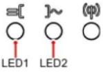 | LED1 LED2 | - | ||
| Steady green | Steady green The SUN2000 is operating in grid-tied mode. | |||
| Blinking green at long intervals (on for 1s and then off for 1s) | Off The DC is on and the | AC is off. | ||
| Blinking green at long intervals (on for 1s and then off for 1s) | Blinking green at long intervals (on for 1s and then off for 1s) | Both the DC and AC are on, and the SUN2000 is not supplying power to the power grid. | ||
| Off Blinking | green at long intervals (on for 1s and then off for 1s) | The DC is off and the AC is on. | ||
| Steady orange | Steady orange The SUN2000 is operating in the off-grid mode. | |||
| Blinking orange slowly | Off The DC is on, and the | SUN2000 has no output in the off-grid mode. | ||
| Blinking orange slowly | Blinking orange slowly The | SUN2000 is operating in the overload in backup mode. | ||
| Off Off Both the DC and AC are | off. | |||
| Blinking red at short intervals (on for 0.2s and then off for 0.2s) | - DC environment alarm. | For example, the input voltage of the PV string is high, the PV string is reversely connected, or the insulation resistance is low. | ||
| - Blinking red | at short intervals | AC environment alarm. For example, the power grid is undervoltage, overvoltage, overfrequency, or underfrequency. | ||
| Steady red | Steady red Fault | |||
Communications indicator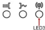 | LED3 - | |||
| Blinking green at short intervals (on for 0.2s and then off for 0.2s) | Communication is in progress. (When a mobile phone is connected to the SUN2000, the indicator blinks green at long intervals, indicating that the phone is connected to the SUN2000.) | |||
| Blinking green at long intervals (on for 1s and then off for 1s) | Mobile phone access | |||
| Off No communication | ||||
| Device replacement indicator | LED1 LED2 | LED3 - | ||
| Steady red | Steady red Ste | ady red The | SUN2000 hardware is faulty and the SUN2000 needs to be replaced. | |
2.3 Label Description
2.3.1 Enclosure Labels
| Symbol | Name Description | |
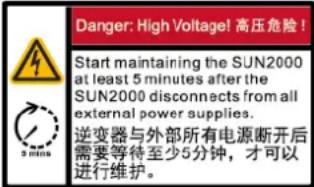 | Delay discharge Residual | voltage exists after the SUN2000 is powered off. It takes 5 minutes for the SUN2000 to discharge to the safe voltage. |
| Symbol Name Description | ||
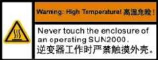 | Burn warning Do not touch | ch a running SUN2000 because it generates high temperatures on the shell. |
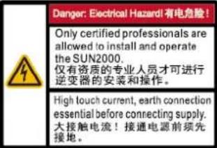 | Electric shock warning • | High voltage exists after the SUN2000 is powered on. Only qualified and trained electrical technicians are allowed to perform operations on the SUN2000.• High touch current exists after the SUN2000 is powered on. Before powering on the SUN2000, ensure that the SUN2000 is properly grounded. |
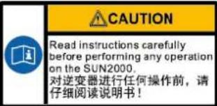 | Refer to documentation | Reminds operators to refer to the documents delivered with the SUN2000. |
 | Grounding label Indicates | the position for connecting the PE cable. |
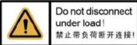 | Operation warning Do not remove the DC input connector or AC output connector when the SUN2000 is running. | |
 (1P)PN/ITEM:XXXXXXX(32P)Model: SUN2000-XKTL-XX(S)SN:XXXXXXXXXXXX MADE IN CHINA (1P)PN/ITEM:XXXXXXX(32P)Model: SUN2000-XKTL-XX(S)SN:XXXXXXXXXXXX MADE IN CHINA | SUN2000 serial number | Indicates the serial number. |
 | SUN2000 MAC address | Indicates the MAC address. |
 | SUN2000 Wi-Fi login QR code | Scan the QR code to connect to the Huawei SUN2000 Wi-Fi network. |
2.3.2 Product Nameplate
Figure 2-5 Nameplate (using SUN2000-10KTL-M1 as an example)
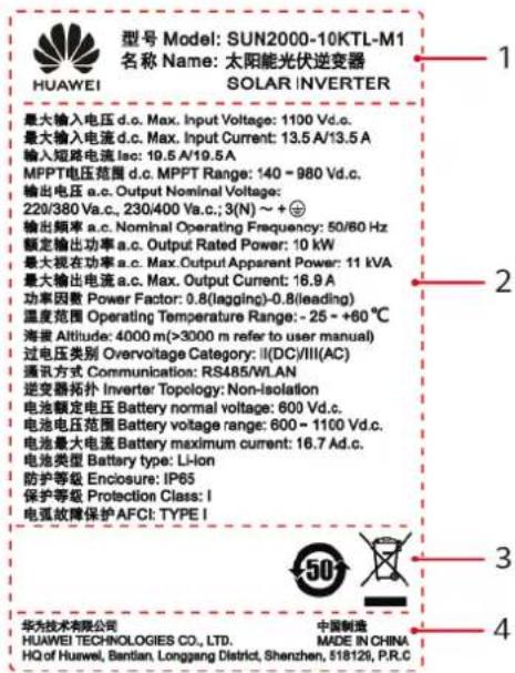
(1) Trademark and product model (2) Key technical parameters
(3) Certification marks (4) Company name and country of origin

NO TE
The nameplate figure is for reference only.
2.4 Working Principles
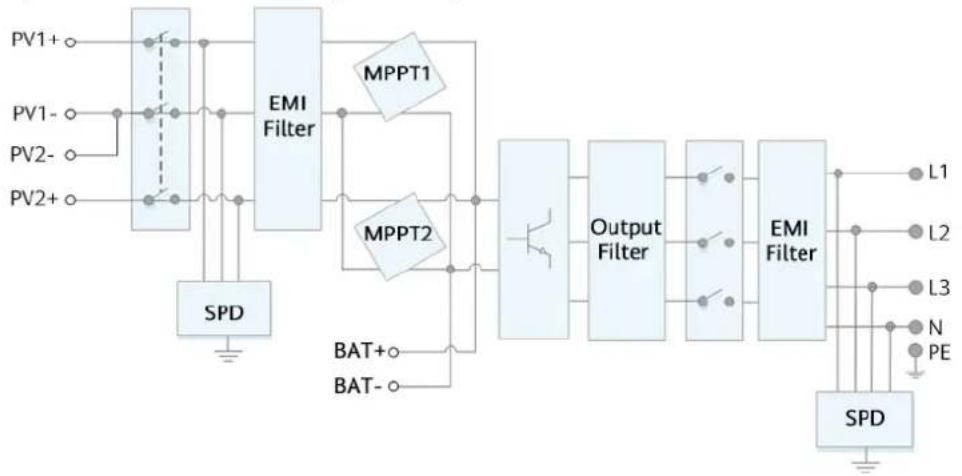
2.4.1 Circuit Diagram
Two PV strings connect to the SUN2000, and their maximum power points are tracked by two maximum power point tracking (MPPT) circuits. The SUN2000
converts DC power into three-phase AC power through an inverter circuit. Surge protection is supported on both the DC and AC sides.
Figure 2-6 SUN2000 conceptual diagram
flowchart
graph TD
    PV1[" PV1+ "] --> EMIFilter["EMI Filter "]
    PV2[" PV2- "] --> EMIFilter
    PV2+[ PV2+ ] --> EMIFilter
    EMIFilter --> MPPT1["MPPT1"]
    EMIFilter --> MPPT2["MPPT2"]
    MPPT1 --> OutputFilter["Output Filter"]
    MPPT2 --> OutputFilter
    OutputFilter --> EMIFilter["EMI Filter"]
    L1[" L1 "] --> OutputFilter
    L2[" L2 "] --> OutputFilter
    L3[" L3 "] --> OutputFilter
    N[" N "] --> OutputFilter
    PE[" PE "] --> OutputFilter
    SPD[" SPD "] --> OutputFilter
    SPD --> BATA[" BAT+ "]
    SPD --> BATAb[" BAT- "]
    BATA --> OutputFilter
    BATAb --> OutputFilter
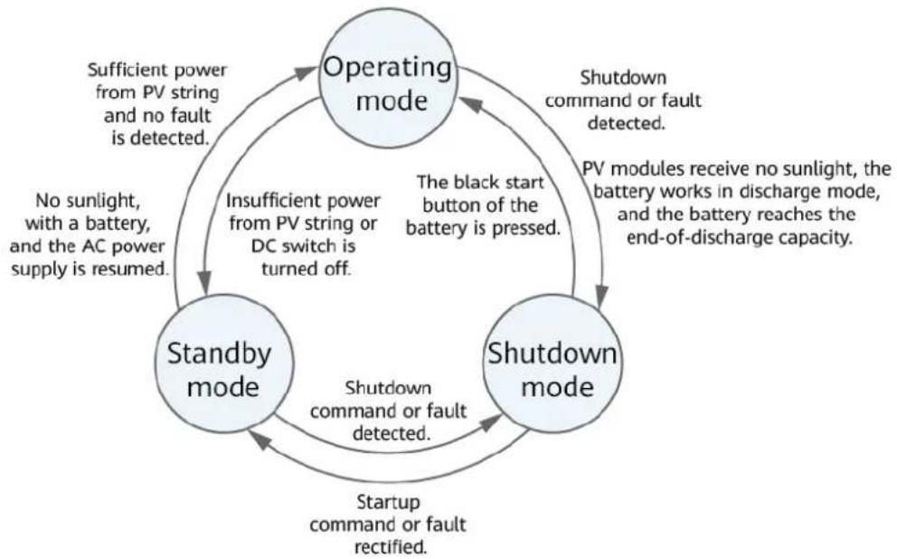
2.4.2 Working Modes
The SUN2000 can work in Standby, Operating, or Shutdown mode.
Figure 2-7 Working modes
flowchart
graph TD
    A["Operating mode"] -->|Sufficient power from PV string and no fault is detected.| B["Standby mode"]
    B -->|Insufficient power from PV string or DC switch is turned off.| A
    A -->|Shutdown command or fault detected.| C["Shutdown mode"]
    C -->|Shutdown command or fault rectified.| B
    B -->|The black start button of the battery is pressed.| A
    A -->|PV modules receive no sunlight, the battery works in discharge mode, and the battery reaches the end-of-discharge capacity.| C
    B -->|No sunlight, with a battery, and the AC power supply is resumed.| A
IS07S00002
Table 2-3 Working mode description
| Working Mode | Description |
| Standby The | SUN2000 enters Standby mode when the external environment does not meet the operating requirements. In Standby mode:The SUN2000 continuously performs status check and enters the Operating mode once the operating requirements are met.The SUN2000 enters Shutdown mode after detecting a shutdown command or a fault after startup. |
| Operating In | Operating mode:The SUN2000 converts DC power from PV strings into AC power and feeds the power to the power grid.The SUN2000 tracks the maximum power point to maximize the PV string output.If the SUN2000 detects a fault or a shutdown command, it enters the Shutdown mode.The SUN2000 enters Standby mode after detecting that the PV string output power is not suitable for connecting to the power grid for generating power.If the PV modules receive no sunlight, the battery works in discharge mode, and the battery reaches the end-of-discharge capacity, the SUN2000 enters Shutdown mode. |
| Shutdown | In Standby or Operating mode, the SUN2000 enters Shutdown mode after detecting a fault or shutdown command.In Shutdown mode, the SUN2000 enters Standby mode after detecting a startup command or that the fault is rectified.In Shutdown mode, if the black start button of the battery is pressed, the SUN2000 enters Operating mode. |
3 Storage
The following requirements should be met if the SUN2000 is not put into use directly:
- Do not unpack the SUN2000.
- Keep the storage temperature at -40^ to +70^ and the humidity at 5% - 95% RH.
- The SUN2000 should be stored in a clean and dry place and be protected from dust and water vapor corrosion.
- A maximum of eight SUN2000s can be stacked. To avoid personal injury or device damage, stack SUN2000s with caution to prevent them from falling over.
- Periodic inspections are required during the storage. Replace the packing materials if necessary.
- If the SUN2000 has been long-term stored, inspections and tests should be conducted by qualified personnel before it is put into use.
4 Installation
4.1 Checking Before Installation
Outer Packing Materials
Before unpacking the inverter, check the outer packing materials for damage, such as holes and cracks, and check the inverter model. If any damage is found or the inverter model is not what you requested, do not unpack the package and contact your supplier as soon as possible.

NO TE
You are advised to remove the packing materials within 24 hours before installing the inverter.
Package Contents
After unpacking the inverter, check that the contents are intact and complete. If any damage is found or any component is missing, contact your supplier.

NO TE
For details about the number of contents, see the Packing List in the packing case.
4.2 Tools
| Type Tool | ||||
| Installation Tools |  Hammer drillDrill bit: Φ8 mm and Φ6 mm Hammer drillDrill bit: Φ8 mm and Φ6 mm | 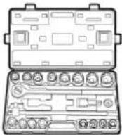 Socket wrench set Torque screwdriverPhillips head: M3 Socket wrench set Torque screwdriverPhillips head: M3 | 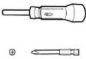 | 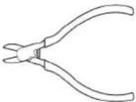 Diagonal pliers Diagonal pliers |
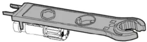
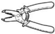 Wire stripper Wire stripper | 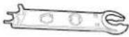 Removal wrenchModel: PV-MS-HZOpen-end Wrench;manufacturer:Staubli Removal wrenchModel: PV-MS-HZOpen-end Wrench;manufacturer:Staubli | 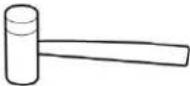 Rubber mallet Utility knife Rubber mallet Utility knife | 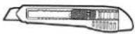 | |
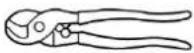 Cable cutter Cable cutter | 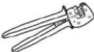 Crimping toolModel: PV-CZM-22100/19100;manufacturer:Staubli Crimping toolModel: PV-CZM-22100/19100;manufacturer:Staubli | 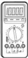 MultimeterDC voltage measurement range ≥ 1100 V DC MultimeterDC voltage measurement range ≥ 1100 V DC | 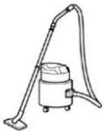 Vacuum cleaner Vacuum cleaner | |
 Marker Measuring tape Marker Measuring tape | 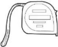 Bubble or digital Bubble or digital | 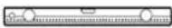 level level | 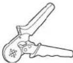 Cord end terminal crimper Cord end terminal crimper | |
 Heat shrink tubing Heat gun Cable tie Hydraulic pliers Heat shrink tubing Heat gun Cable tie Hydraulic pliers | 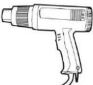 | 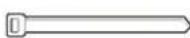 | 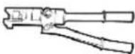 | |
| PPE |  Safety gloves Safety goggles Anti-dust respirator Safety gloves Safety goggles Anti-dust respirator | 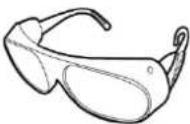 |  |  Safety shoes Safety shoes |
4.3 Determining the Installation Position
4.3.1 Environment Requirements
Basic Requirements
- The SUN2000 is protected to IP65 and can be installed indoors or outdoors.
- Do not install the SUN2000 in a place where personnel are easy to come into contact with its enclosure and heat sinks, because these parts are extremely hot during operation.
- Do not install the SUN2000 in areas with flammable or explosive materials.
- Do not install the SUN2000 at a place within children's reach.
- Do not install the SUN2000 outdoors in salt areas because it will be corroded there and may cause fire. A salt area refers to the region within 500 meters from the coast or prone to sea breeze. The regions prone to sea breeze vary depending on weather conditions (such as typhoons and monsoons) or terrains (such as dams and hills).
- The SUN2000 must be installed in a well-ventilated environment to ensure good heat dissipation.
- Recommended: Install the SUN2000 in a sheltered place or a place with an awning.
Mounting Structure Requirements
- The mounting structure where the SUN2000 is installed must be fireproof.
- Do not install the SUN2000 on flammable building materials.
- The SUN2000 is heavy. Ensure that the installation surface is solid enough to bear the weight load.
- In residential areas, do not install the SUN2000 on drywalls or walls made of similar materials which have a weak sound insulation performance because the noise generated by the SUN2000 is noticeable.
4.3.2 Space Requirements
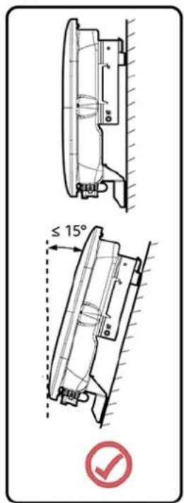
Installation Angle Requirements
The SUN2000 can be wall-mounted or pole-mounted. The installation angle requirements are as follows:
- Install the SUN2000 vertically or at a maximum back tilt of 15 degrees to facilitate heat dissipation.
- Do not install the SUN2000 at forward tilted, excessive back tilted, side tilted, horizontal, or upside down positions.
Figure 4-1 Installation tilts
IS10H00012
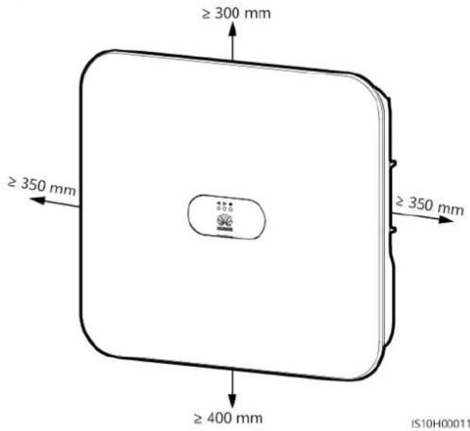
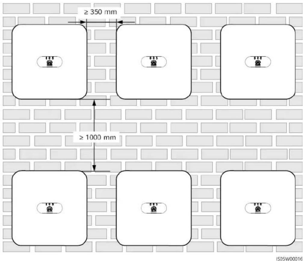
Installation Space Requirements
- Reserve enough space around the SUN2000 to ensure sufficient space for installation and heat dissipation.
Figure 4-2 Installation space
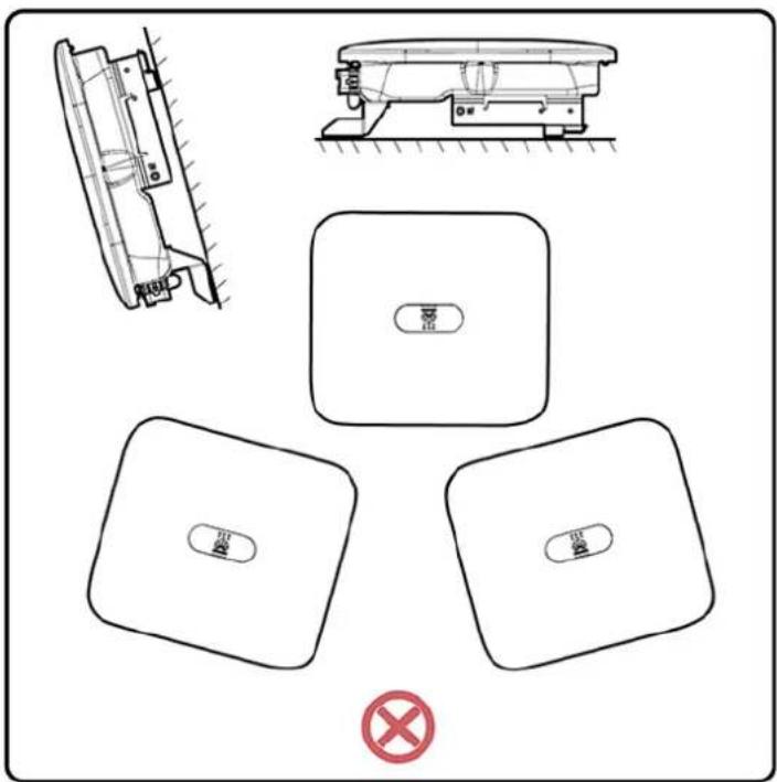
- When installing multiple SUN2000s, install them in horizontal mode if sufficient space is available and install them in triangle mode if no sufficient space is available. Stacked installation is not recommended.
Figure 4-3 Horizontal installation (recommended)
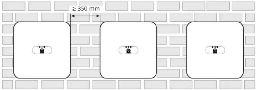
IS10H00014
Figure 4-4 Staggered installation (recommended)
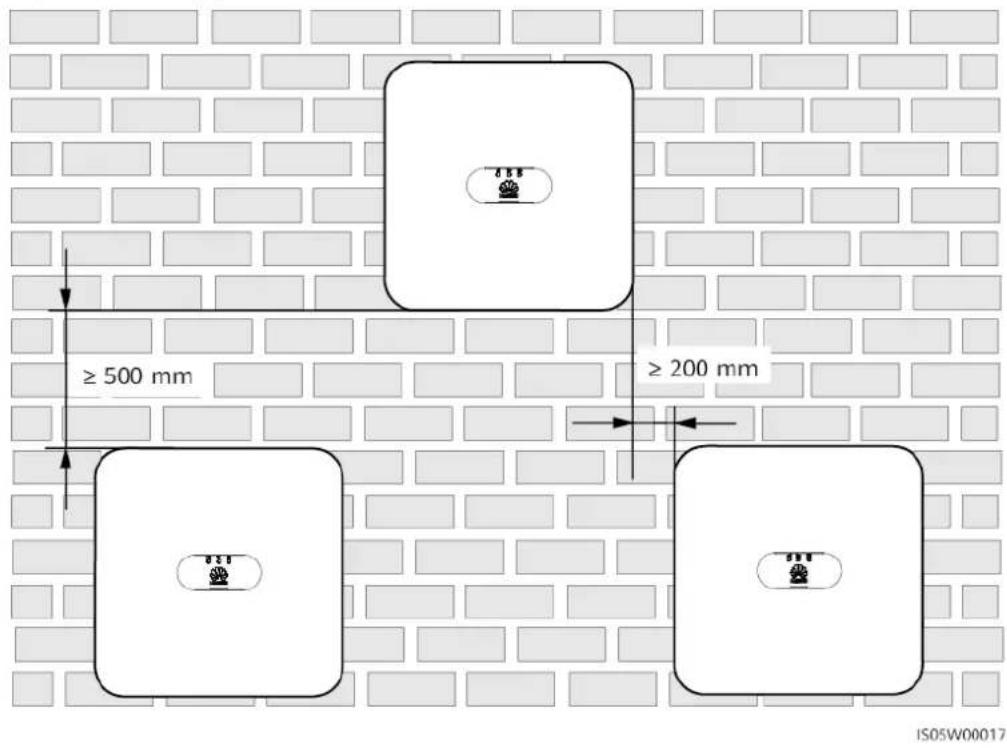
Figure 4-5 Stacked installation (not recommended)
4.4 Moving the SUN2000
Procedure
Step 1 Two persons are required to move the SUN2000 with one person on both sides. Lift the SUN2000 from the packing case and move it to the specified installation position.

CA UTION
- Move the SUN2000 with care to prevent device damage and personal injury.
- Do not use the wiring terminals and ports at the bottom to support any weight of the SUN2000.
- Place a foam pad or cardboard under the SUN2000 to protect the SUN2000 enclosure from damage.
Figure 4-6 Moving the SUN2000
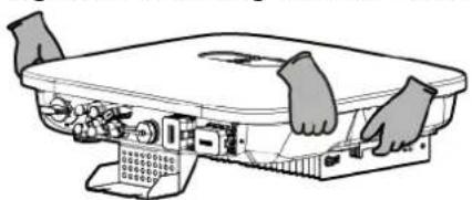
natural_image
Diagram of hands operating a device with ports and connectors (no text or symbols)----End
4.5 Installing the Mounting Bracket
Installation Precautions
Figure 4-7 shows the dimensions of installation holes on the SUN2000.
Figure 4-7 Mounting bracket dimensions
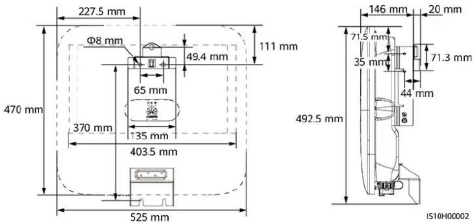
NO TE
Two M6 screw holes are reserved on both left and right sides of the enclosure for installing an awning.
4.5.1 Wall-mounted Installation
Procedure
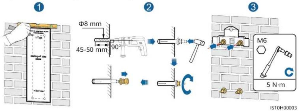
Step 1 Determine the positions for drilling holes and mark the positions using a marker.
Step 2 Secure the mounting bracket.
NO TE
M6x60 expansion bolts are delivered with the SUN2000. If the length and number of the bolts do not meet installation requirements, prepare M6 stainless steel expansion bolts by yourself.
Figure 4-8 Expansion bolt composition
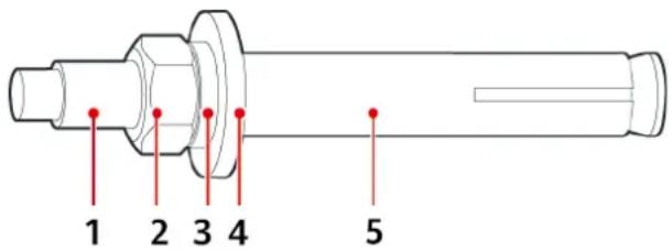
IS05W00018
(1) Bolt (2) Nut (3) Spring washer
(4) Flat washer (5) Expansion sleeve
D ANGER
Avoid drilling holes in the water pipes and cables buried in the wall.
NO TICE
- To prevent dust inhalation or contact with eyes, wear safety goggles and an anti-dust mask when drilling holes.
- Clean up any dust in and around the holes using a vacuum cleaner and measure the distance between holes. If the holes are inaccurately positioned, drill holes again.
- Level the top of the expansion sleeve with the concrete wall after removing the bolt, spring washer, and flat washer. Otherwise, the mounting bracket will not be securely installed on the concrete wall.
- Loosen the nuts, flat washers, and spring washers of the two expansion bolts below.
Figure 4-9 Installing the mounting bracket
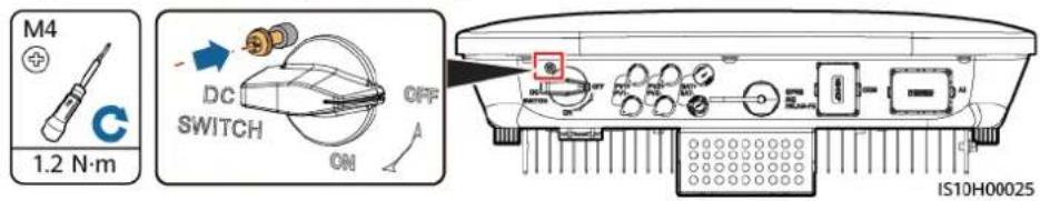
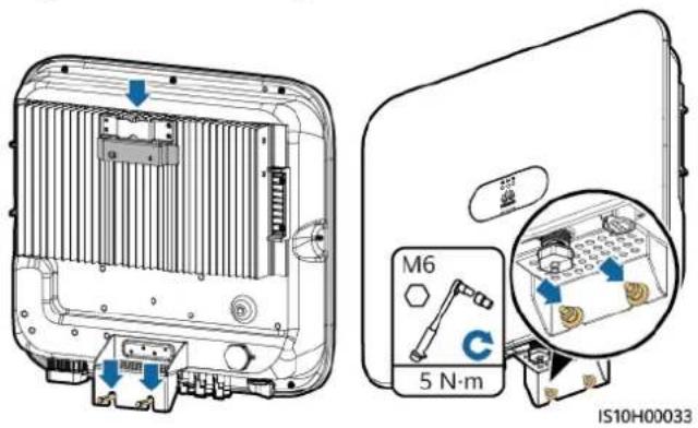
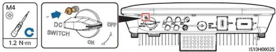
Step 3 (Optional) Install the locking screw for the DC switch.
NO TE
- The locking screw for the DC switch is delivered with the SUN2000. According to the Australian standard, the locking screw is used to secure the DC switch to prevent the SUN2000 from being started by mistake.
- For the model used in Australia, perform this step based on the local standards.
Figure 4-10 Installing the locking screw for the DC switch
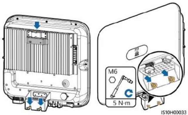
Step 4 Install the SUN2000 onto the mounting bracket.
Step 5 Tighten the nut.
Figure 4-11 Installing a SUN2000
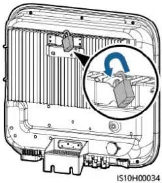
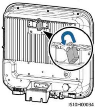
Step 6 (Optional) Install an anti-theft lock.
NO TICE
- Prepare an anti-theft lock suitable for the lock hole diameter (Φ8 mm) by yourself. Ensure that the lock can be installed successfully.
• Outdoor waterproof lock is recommended. - Keep the key to the anti-theft lock properly.
Figure 4-12 Installing an anti-theft lock
natural_image
Technical diagram of a mechanical component with an inset showing a close-up view of a lock mechanism (no text or symbols present)----End
4.5.2 Support-mounted Installation
Prerequisites
Prepare M6 stainless bolt assemblies (including flat washers, spring washers, and M6 bolts) with appropriate lengths as well as matched flat washers and nuts based on the support specifications.
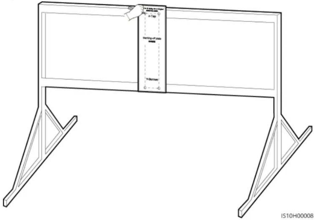
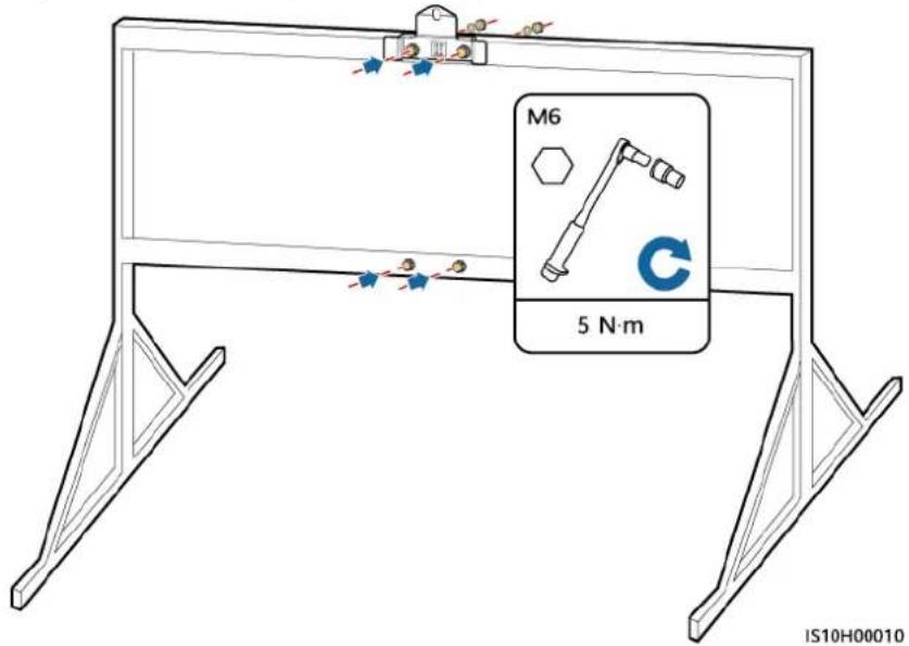
Procedure
Step 1 Determine the hole positions based on the marking-off template, and then mark the hole positions using a marker.
Figure 4-13 Determining the positions for drilling holes
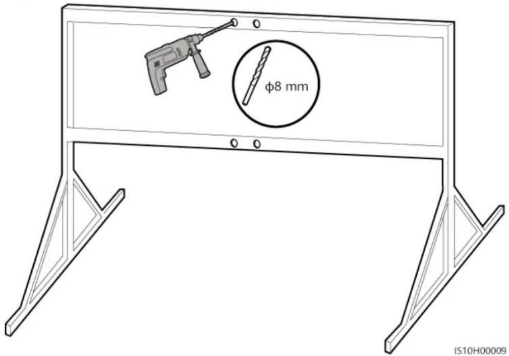
Step 2 Drill holes using a hammer drill.
NO TE
You are advised to apply anti-rust paint on the hole positions for protection.
Figure 4-14 Drilling holes
Step 3 Secure the mounting bracket.
Figure 4-15 Securing the mounting bracket
Step 4 (Optional) Install the locking screw for the DC switch.
NO TE
- The locking screw for the DC switch is delivered with the SUN2000. According to the Australian standard, the locking screw is used to secure the DC switch to prevent the SUN2000 from being started by mistake.
- For the model used in Australia, perform this step based on the local standards.
Figure 4-16 Installing the locking screw for the DC switch
Step 5 Install the SUN2000 onto the mounting bracket.
Step 6 Tighten bolt assemblies.
Figure 4-17 Installing a SUN2000
Step 7 (Optional) Install an anti-theft lock.
NO TICE
- Prepare an anti-theft lock suitable for the lock hole diameter ( 8 mm) by yourself. Ensure that the lock can be installed successfully.
- Outdoor waterproof lock is recommended.
- Keep the key to the anti-theft lock properly.
Figure 4-18 Installing an anti-theft lock
natural_image
Interior view of a device showing internal components and a magnified inset highlighting a switch mechanism (no text or symbols present)----End
5 Electrical Connections
5.1 Installation Preparation
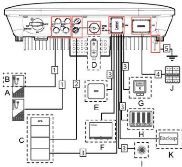
Figure 5-1 SUN2000 cable connections (dashed boxes indicate optional components)
flowchart
graph TD
    A["Device 1"] --> B["Switch"]
    C["Device 2"] --> D[" meters"]
    E["Device 3"] --> F[" relays"]
    G["Device 4"] --> H[" backup"]
    I["Device 5"] --> J[" relay"]
    K["Device 6"] --> L[" switch"]
    M["Device 7"] --> N[" meters"]
    O["Device 8"] --> P[" relays"]
    Q["Device 9"] --> R[" backup"]
    S["Device 10"] --> T[" switch"]
    U["Device 11"] --> V[" meters"]
    W["Device 12"] --> X[" relays"]
    Y["Device 13"] --> Z[" backup"]
NO TICE
If a Smart Dongle is configured, it is recommended that you install it before connecting the signal cable.
Table 5-1 Component description
| No. Component Description Source | |||
| A PV module ● A PV string | is composed of the PV modules connected in series and can work with an optimizer.● The SUN2000 supports the input from two PV strings. | Prepared by users | |
| B (Optional)Smart PV optimizer | The SUN2000-450W-P smart PV optimizer is supported. | Purchased from Huawei | |
| C (Optional)Battery | The LUNA2000-5-S0, LUNA2000-10-S0, and LUNA2000-15-S0 batteries can be connected to the SUN2000. | Purchased from Huawei | |
| D (Optional)Smart Dongle ^1 | Supported models:● WLAN-FE Smart Dongle: SDongleA-05● 4G Smart Dongle: SDongleA-03 | Purchased from Huawei | |
| E (Optional)SUN2000 | Select a proper model as required. | Purchased from Huawei | |
| F (Optional)SmartLogger | Select a proper model as required. | Purchased from Huawei | |
| G (Optional)Power meter | The DTSU666-H power meter is recommended. | Purchased from Huawei | |
| H (Optional)Power grid scheduling device | Select the devices that meet the power grid scheduling requirements. | Provided by the local power grid company | |
| I (Optional)Rapid shutdown switch | Select a proper model as required. | Prepared by users | |
| J AC switch | Recommended | a three-phaseAC circuit breaker with a rated voltage greater than or equal to 380 V AC and a rated current of:16 A (SUN2000-3KTL-M1, SUN2000-4KTL-M1, SUN2000-5KTL-M1, and SUN2000-6KTL-M1)25 A (SUN2000-8KTL-M1 and SUN2000-10KTL-M1) | Prepared by users |
| K (Optional)Smart Backup Box | Select a proper model as required. | Purchased from Huawei | |
| Note 1:For details about how to operate the WLAN-FE Smart Dongle SDongleA-05, see SDongleA-05 Quick Guide (WLAN-FE).For details about how to operate the 4G Smart Dongle SDongleA-03, see SDongleA-03 Quick Guide (4G).You can obtain the quick guide athttps://support.huawei.com/enterprise/en/index.htmlby searching for the Smart Dongle model. | |||
Table 5-2 Cable description
| No. | Name Type Recommended | Specifications | |
| 1 DC input power cable common outdoor PV cable in the industry (Recommended model: PV1-F) | Conductor cross-sectional area: 4-6 mm2Cable outer diameter: 5.5-9 mm | ||
| 2 (Optional) Battery cable | |||
| 3 (Optional) Signal cablea | Outdoor shielded twisted pair | Conductor cross-sectional area: 0.2-1 mm2Cable outer diameter: 4-11 mm | |
| No. Name Type Recommended | Specifications | ||
| 4 AC output power cable^b | Outdoor copper cable ● | Conductor cross-sectional area: 4-6 mm^2 ● Cable outer diameter: 10-21mm | |
| 5 PE cable Single-core outdoor | copper-core cable | Conductor cross-sectional area: ≥ 4 mm^2 | |
| Note a: When the smart power sensor and battery are connected to the SUN2000 at the same time, use a cable core with a cross-sectional area of 0.2 mm^2 to 0.5 mm^2 .Note b: The minimum cable diameter depends on the fuse rating on the AC side. | |||

NO TE
- The minimum cable diameter should comply with the local cable standard.
- Factors influencing cable selection are as follows: rated current, type of cable, routing method, ambient temperature, and maximum desired line losses.
5.2 Connecting the PE cable
Important Notes

D ANGER
- Ensure that the PE cable is securely connected. Otherwise, electric shocks may occur.
- Do not connect the N wire to the enclosure as a PE cable. Otherwise, electric shocks may occur.

NO TE
- The PE point at the AC output port is used only as a PE equipotential point, not a substitute for the PE point on the enclosure.
- It is recommended that silica gel or paint be applied around the ground terminal after the PE cable is connected.
Supplementary Notes
The SUN2000 has the grounding detection function. This function is used to check whether the SUN2000 is properly grounded before the SUN2000 starts, or check
whether the SUN2000 ground cable is disconnected when the SUN2000 is running. This function is used to check whether the SUN2000 is properly grounded under limited conditions. To ensure the safe operation of the SUN2000, properly ground the SUN2000 according to the connection requirements of the ground cable. For some power grid types, if the output side of the SUN2000 is connected to an isolation transformer, ensure that the SUN2000 is properly grounded and set Isolation to Input ungrounded, with TF to enable the SUN2000 to run properly.
- According to IEC 62109, to ensure the safe operation of the SUN2000 in the case of ground cable damage or disconnection, properly connect the ground cable of the SUN2000 and ensure that it meets at least one of the following requirements before the grounding detection function becomes invalid.
- The ground cable is a single-core outdoor copper cable with a conductor cross-sectional area greater than or equal to 10 ~mm^2 .
- Use cables with the same diameter as the AC output power cable and ground the PE terminal on the AC connector and the ground screw on the chassis.
- In some countries and regions, the SUN2000 must have additional ground cables. Use cables with the same diameter as the AC output power cable and ground the PE terminal on the AC connector and the ground screw on the chassis.
Procedure
Step 1 Crimp OT terminals.
NO TICE
- Avoid scratching the core wire when stripping a cable.
- The cavity formed after the conductor crimp strip of the OT terminal is crimped must wrap the core wires completely. The core wires must contact the OT terminal closely.
- Wrap the wire crimping area with heat shrink tubing or PVC insulation tape. The heat shrink tubing is used as an example.
- When using a heat gun, protect devices from being scorched.
Figure 5-2 Crimping an OT terminal
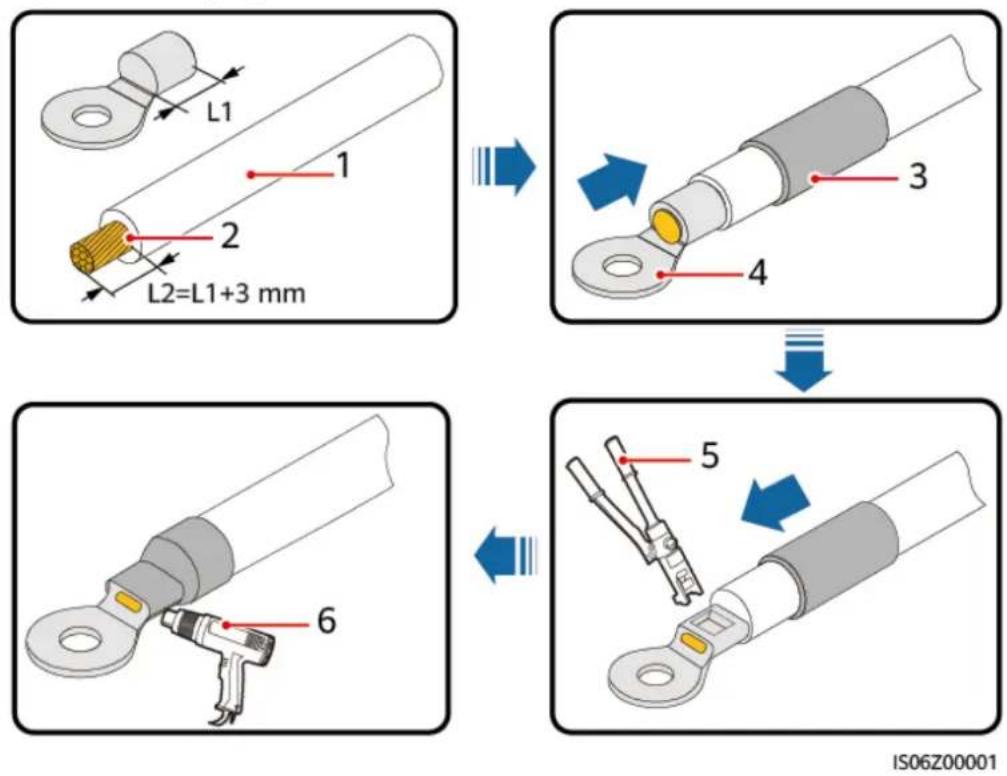
(1) Cable (2) Core (3) Heat shrink tubing
(4) OT terminal (5) Crimping tool (6) Heat gun
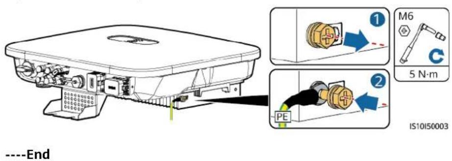
Step 2 Connect the PE cable.
Figure 5-3 Connecting the PE cable
5.3 Connecting the AC Output Power Cable
Precautions
A three-phase AC switch needs to be installed on the AC side of the SUN2000. To ensure that the SUN2000 can safely disconnect itself from the power grid when an
exception occurs, select a proper overcurrent protection device in compliance with local power distribution regulations.

WARNING
Do not connect loads between the SUN2000 and the AC switch directly connected to it.
The SUN2000 is integrated with a comprehensive residual current monitoring unit. Once detecting that the residual current exceeds the threshold, the SUN2000 immediately disconnects itself from the power grid.
NO TICE
- If the external AC switch can perform earth leakage protection, the rated leakage action current should be greater than or equal to 100 mA.
- If multiple SUN2000s connect to the general residual current device (RCD) through their respective external AC switches, the rated leakage action current of the general RCD should be greater than or equal to the number of SUN2000s multiplied by 100 mA.
- A knife switch cannot be used as an AC switch.
Procedure
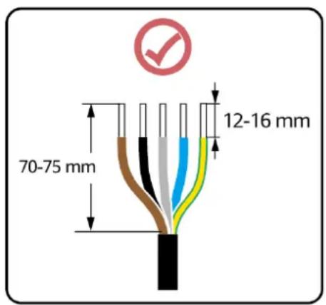
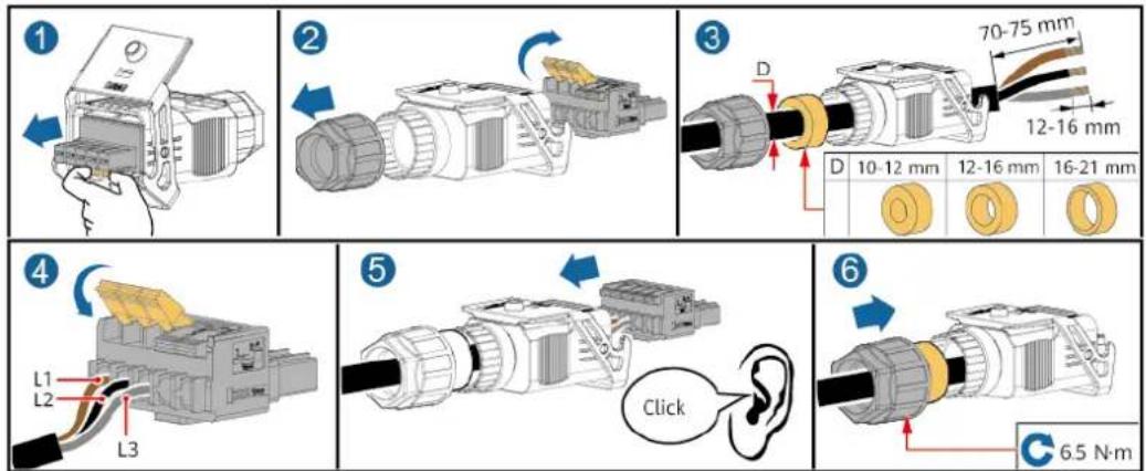
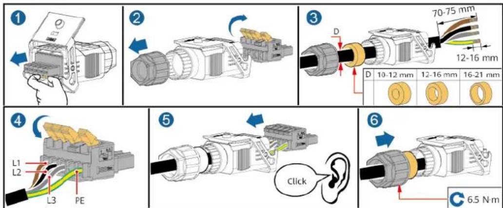
Step 1 Connect the AC output power cable to the AC connector.
Figure 5-4 Stripping requirements
IS06I20048
NO TICE
- Ensure that the cable jacket is inside the connector.
- Ensure that the exposed core wire is totally inserted into the cable hole.
- Ensure that AC terminations provide firm and solid electrical connections. Failing to do so may cause SUN2000 malfunction and damage to its AC connectors.
- Ensure that the cable is not twisted.
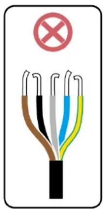
Figure 5-5 Three-core cable (L1, L2, and L3)
IS10I20004
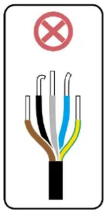
Figure 5-6 Four-core cable (L1, L2, L3, and PE)
IS10I20003
Figure 5-7 Four-core cable (L1, L2, L3, and N)
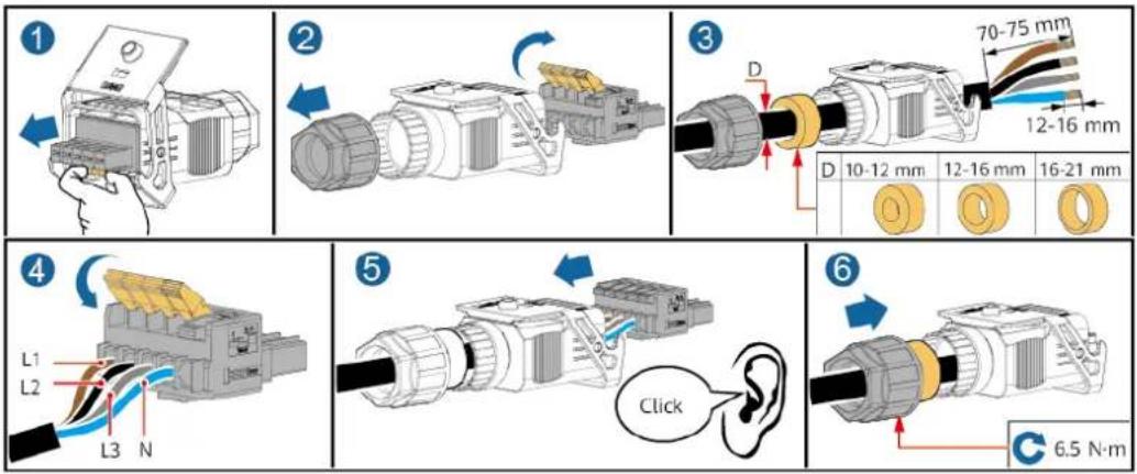
IS10I20002
Figure 5-8 Five-core cable (L1, L2, L3, N, and PE)
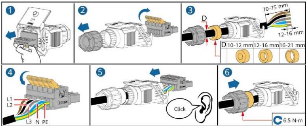
IS10I20001
NO TE
The cable colors shown in the figures are for reference only. Select an appropriate cable according to local standards.
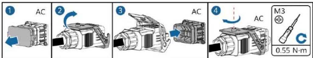
Step 2 Connect the AC connector to the AC output port.
NO TICE
Ensure that the AC connector is connected securely.
Figure 5-9 Securing the AC connector
IS10I20005
Step 3 Check the route of the AC output power cable.
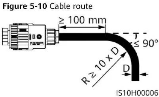
----End
Disconnection
Disconnection can be performed in reverse order.
5.4 Installing DC input power cables
Important Notes

D ANGER
- Before connecting the DC input power cable, ensure that the DC voltage is within the safe range (lower than 60 V DC) and that the DC switch on the SUN2000 is OFF. Otherwise, electric shocks may occur.
- When the SUN2000 is operating, it is not allowed to work on the DC input power cables, such as connecting or disconnecting a PV string or a PV module in a PV string. Otherwise, electric shocks may occur.
- If no PV string connects to a DC input terminal of the SUN2000, do not remove the watertight cap from the DC input terminals. Otherwise, the IP rating of the SUN2000 will be affected.
WARNING
Ensure that the following conditions are met. Otherwise, the SUN2000 may be damaged, or even fire could happen.
- PV modules connected in series in each PV string are of the same specifications.
- The open-circuit voltage of each PV string must always be 1100 V DC or lower.
- The maximum short-circuit current of each PV string must always be 15 A or lower.
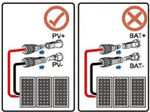
- The polarities of electric connections are correct on the DC input side. The positive and negative terminals of a PV string connect to corresponding positive and negative DC input terminals of the SUN2000.
- If polarity of the DC input power cable is reversed, do not turn off the DC switch immediately or remove positive and negative connectors. Wait until the solar irradiance declines at night and the PV string current reduces to below 0.5 A, and then turn off the DC switch and remove the positive and negative connectors. Correct the PV string polarity before reconnecting the PV string to the SUN2000.
NO TICE
- Since the output of the PV string connected to the SUN2000 cannot be grounded, ensure that the PV module output is well insulated to ground.
- During the installation of PV strings and the SUN2000, the positive or negative terminals of PV strings may be short-circuited to ground if the power cable is not properly installed or routed. In this case, an AC or DC short circuit may occur and damage the SUN2000. The caused device damage is not covered under any warranty.
Terminal Description
Figure 5-11 Terminal
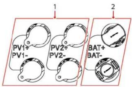
(1) DC input terminal
(2) Battery terminal
Figure 5-12 Correct wiring terminals
IS10H30010
Procedure
Step 1 Install the DC input power cables.

WARNING
Before inserting the positive and negative connectors into the positive and negative DC input terminals of the SUN2000, ensure that the DC switch is set to OFF.

CA UTION
Use the positive and negative Staubli MC4 metal terminals and DC connectors supplied with the SUN2000. Using incompatible positive and negative metal terminals and DC connectors may result in serious consequences. The caused device damage is not covered under warranty.
NO TICE
- Cables with high rigidity, such as armored cables, are not recommended as DC input power cables, because poor contact may be caused by the bending of the cables.
- Before assembling DC connectors, label the cable polarities correctly to ensure correct cable connections.
- After crimping the positive and negative metal terminals, pull back the DC input power cables to ensure that they are securely connected.
- Insert the crimped metal terminals of the positive and negative power cables into the appropriate positive and negative connectors. Then pull back the DC input power cables to ensure that they are connected securely.
- If a DC input power cable is reversely connected and the DC switch is turned on, do not operate on the DC switch or the positive/negative connectors immediately. Otherwise, the device may be damaged. The caused device damage is not covered under any warranty. Wait until the solar irradiance declines at night and the PV string current reduces to below 0.5 A, and then turn off the DC switch and remove the positive and negative connectors. Correct the PV string polarity before reconnecting the PV string to the SUN2000.

NO TE
- The DC voltage measurement range of the multimeter must be at least 1100 V.
- If the voltage is a negative value, the DC input polarity is incorrect. Correct the polarity.
- If the voltage is greater than 1100 V DC, too many PV modules configured to the same string. Remove some PV modules.
- If the PV string is configured with an optimizer, check the cable polarity by referring to the smart PV optimizer quick guide.
Figure 5-13 Installing DC input power cables
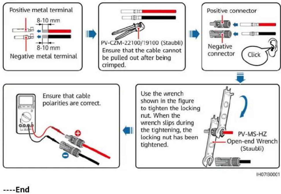
flowchart
graph TD
    A["Positive metal terminal"] --> B["Negative metal terminal"]
    B --> C["PV-CZM-22100/19100 (Staubli) Ensure that the cable cannot be pulled out after being crimped."]
    C --> D["Positive connector"]
    D --> E["Click"]
    E --> F["Use the wrench shown in the figure to tighten the locking nut. When the wrench slips during the tightening, the locking nut has been tightened."]
    F --> G["PV-MS-HZ Open-end Wrench (Staubli)"]
    G --> H["End"]
Removing DC Connectors

WARNING
Before removing the positive and negative connectors, ensure that the DC switch is OFF.
To remove the positive and negative connectors from the SUN2000, insert an open-end wrench into the bayonet and press the wrench with force. Then remove the DC connectors with caution.
Figure 5-14 Removing DC connectors
natural_image
Technical illustration of a mechanical clamp or connector assembly (no text or symbols visible)IH07H00019
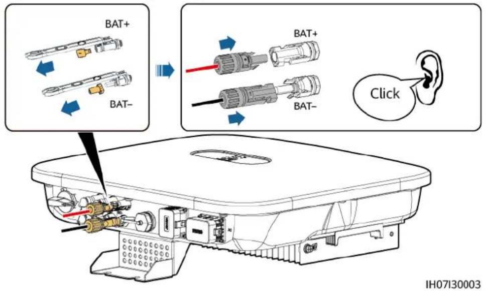
5.5 (Optional) Connecting Battery Cables
Prerequisites

D ANGER
- Battery short-circuit may cause personal injury. The high transient current generated by a short-circuit may release a surge of energy and cause fire.
- Do not connect or disconnect the battery cables when the SUN2000 is running. Otherwise, electric shocks may occur.
- Before connecting the battery cables, ensure that the DC switch on the SUN2000 and all the switches connecting to the SUN2000 are OFF, and the SUN2000 has no residual electricity. Otherwise, the high voltage of the SUN2000 and battery may result in electric shocks.
- If no battery connects to the SUN2000, do not remove the watertight caps from the battery terminals. Otherwise, the protection level of the SUN2000 will be affected. If a battery connects to the SUN2000, set aside the watertight caps. Reinstall the watertight caps immediately after removing the connectors.
A battery switch can be configured between the SUN2000 and the battery to ensure that the SUN2000 can be safely disconnected from the battery.
WARNING
- Do not connect loads between the SUN2000 and the battery.
- The battery cables should be connected correctly. That is, the positive and negative terminals of the battery connect to the positive and negative battery terminals on the SUN2000 respectively. Otherwise, the SUN2000 may be damaged, or even fire could happen.
NO TICE
- During the installation of batteries and the SUN2000, the positive or negative terminals of batteries may be short-circuited to ground if the power cable is not properly installed or routed. In this case, an AC or DC short circuit may occur and damage the SUN2000. The caused device damage is not covered under any warranty.
- The cabling distance between the battery and the SUN2000 should be less than or equal to 10 meters (recommended: within 5 meters).
Procedure
Step 1 Assemble the positive and negative connectors by referring to 5.4 Installing DC input power cables.
D ANGER
- The battery voltage may result in serious injury. Use dedicated insulation tools when connecting cables.
- Ensure that cables are correctly connected between the battery terminal and the battery switch, and between the battery switch and the SUN2000 battery terminal.
NO TICE
Cables with high rigidity, such as armored cables, are not recommended as battery cables, because poor contact may be caused by the bending of the cables.
Step 2 Insert the positive and negative connectors into corresponding battery terminals on the SUN2000.
NO TICE
After the positive and negative connectors snap into place, pull the battery cables back to ensure that they are connected securely.
Figure 5-15 Connecting battery cables
----End
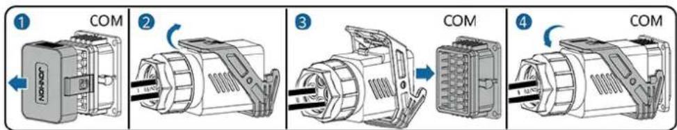
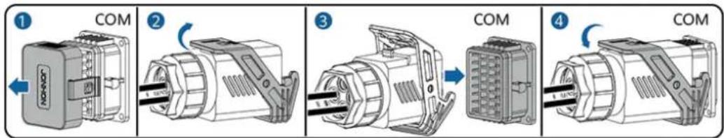
5.6 Install the Smart Dongle
Procedure
NO TE
- If WLAN-FE communication is used, install the WLAN-FE Smart Dongle (SDongleA-05). The WLAN-FE Smart Dongle is delivered with the SUN2000.
- If 4G communication is used, install the 4G Smart Dongle (SDongleA-03). The 4G Smart Dongle needs to be purchased by the user.
- WLAN-FE Smart Dongle (FE Communication)
You are advised to use a Cat 5e outdoor shielded network cable (outer diameter < 9 mm; internal resistance ≤ 1.5 ohms/10 m) and shielded RJ45 connectors.
Figure 5-16 Installing a WLAN-FE Smart Dongle (FE communication)
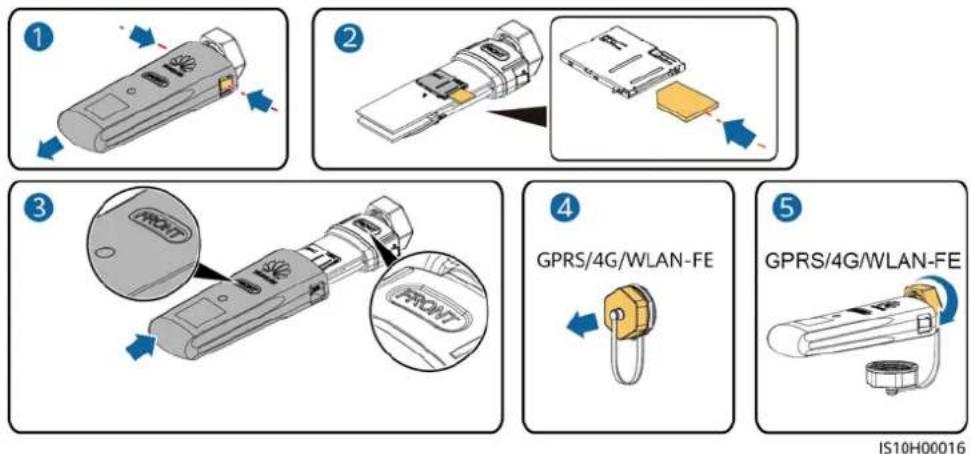
- (Optional) 4G Smart Dongle (4G communication)
NO TE
- If your Smart Dongle is not equipped with a SIM card, prepare a standard SIM card (size: 25 mm x 15 mm) with the capacity greater than or equal to 64 KB.
- When installing the SIM card, determine its installation direction based on the silk screen and arrow on the card slot.
- Press the SIM card in place to lock it, indicating that the SIM card is correctly installed.
- When removing the SIM card, push it inwards to eject it.
- When reinstalling the shell of the Smart Dongle, ensure that the buckle springs back in place and a click sound is generated.
Figure 5-17 Installing a 4G Smart Dongle

NO TE
There are two types of Smart Dongle.
- For details about how to operate the WLAN-FE Smart Dongle SDongleA-05, see SDongleA-05 Quick Guide (WLAN-FE). You can also scan the QR code to obtain the document.

- For details about how to operate the 4G Smart Dongle SDongleA-03, see SDongleA-03 Quick Guide (4G). You can also scan the QR code to obtain the document.

The quick guide is delivered with the Smart Dongle.
5.7 (Optional) Connecting the Signal Cable
COM Port Pin Definitions
NO TICE
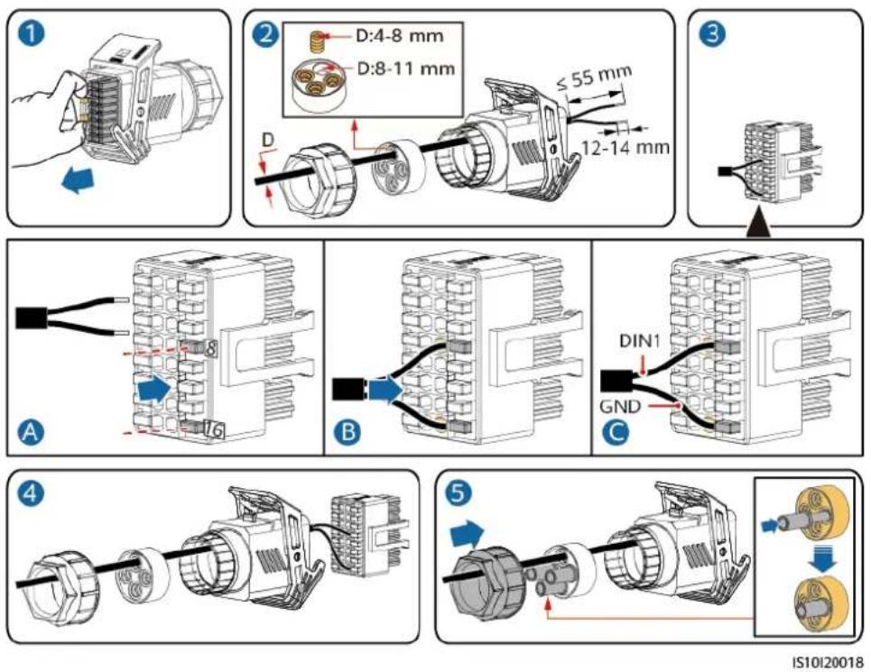
- When laying out the signal cable, separate it from the power cable and keep it away from strong interference sources to avoid strong communication interference.
- Ensure that the protective layer of the cable is inside the connector, that excess core wires are cut off from the protection layer, that the exposed core wire is totally inserted into the cable hole, and that the cable is connected securely.
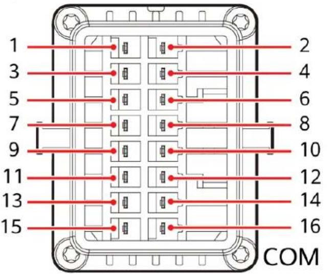
Figure 5-18 Pin definitions
IS10W00002
NO TE
- If the RS485 communications cables of devices such as the smart power sensor and battery are connected to the SUN2000 at the same time, the pins RS485A2 (pin 7), RS485B2 (pin 9), and PE (pin 5) are shared.
- If both the battery enable signal cable and rapid shutdown switch signal cable are connected to the SUN2000 at the same time, the GND pin (pin 13) is shared.
| Pin | Definition | Functions Remarks | Pin Definiti | on | Functions Remarks | ||
| 1 485 | A1-1 RS485A,RS485differential signal+ | Used for SUN2000cascading or connecting to the RS485 signal port on theSmartLogger | 2 485A | 1-2 | RS485A,RS485differential signal+ | Used for SUN2000cascading or connecting to the RS485 signal port on theSmartLogger | |
| 3 485 | B1-1 RS485B,RS485differential signal- | 4 485B | 1-2 RS485B,RS485differential signal- | ||||
| 5 PE | Ground pointon the shield layer | -6 PE Ground | point on the shield layer | - |
| Pin Definition | Functions Remarks Pin Definiti | on | Functions Remarks | |||
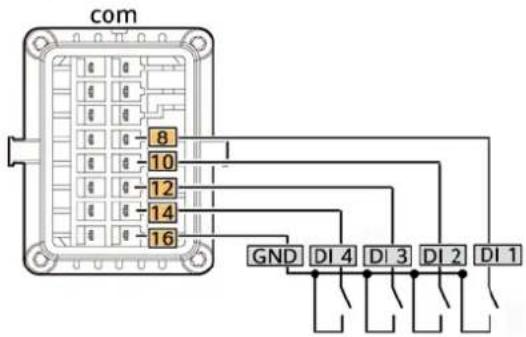
| 7 485A2 RS485A, | RS485 differential signal+ | Used to connect to the RS485 signal port on a power meter or battery | 8 DIN1 | Digital input signal 1+ | Used to connect to dry contacts for grid scheduling or serve as a port for the feedback signal of the Backup Box. | |
| 9 485B2 RS485B, | RS485 differential signal- | 10 DIN2 | Digital input signal 2+ | Used to connect to dry contacts for grid scheduling | ||
| 11 EN Enable signal Used to | connect to the enable signal of the battery. | 12 DIN3 | Digital input signal 3+ | |||
| 13 GND GND - | 14 | DIN4 Digital input | signal 4+ | |||
| 15 DIN5 Rapid | shutdown | Used to connect to the rapid shutdown DI signal port or serve as a port for the signal cable of the NS protection. | 16 GND | GND of | DI1/DI2/DI3/DI4 | Used to connect to the GND of DI1/DI2/DI3/DI4 |
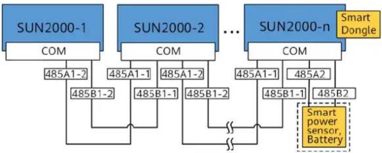
Networking Modes
- Smart Dongle networking
Figure 5-19 Smart Dongle networking (the dashed box indicates optional components)
flowchart
graph TD
    A["SUN2000-1"] -->|COM 485A1-2| B["SUN2000-2"]
    B -->|COM 485A1-1| C["SUN2000-n"]
    C -->|COM 485A1-2| D["SUN2000-n"]
    D -->|COM 485A1-1| E["Smart Dongle Sensor"]
    D -->|COM 485A2| F["Smart Dongle Sensor"]
    B -->|COM 485B1-2| G["Smart Dongle Sensor"]
    C -->|COM 485B1-1| H["Smart Dongle Sensor"]
    C -->|COM 485B2| I["Smart Dongle Sensor"]
    style A fill:#333,stroke:#fff,color:#fff
    style B fill:#333,stroke:#fff,color:#fff
    style C fill:#333,stroke:#fff,color:#fff
    style D fill:#333,stroke:#fff,color:#fff
    style E fill:#333,stroke:#fff,color:#fff
    style F fill:#333,stroke:#fff,color:#fff
    style G fill:#333,stroke:#fff,color:#fff
    style H fill:#333,stroke:#fff,color:#fff
    style I fill:#333,stroke:#fff,color:#fff
Table 5-3 Usage Restrictions
| Smart Dongle Usage | Restrictions | Actual Connection | |
| Maximum Number of Devices That Can Be Connected to the Smart Dongle | Number of SUN2000s | Number of Other Devices^a | |
| 4G 10 n ≤ 10 ≤ 10-n | |||
| WLAN-FE 10 n ≤ 10 ≤ 10-n | |||
| Note a: If the power meter and battery are connected through the RS485A2 and RS485B2 ports, they are not included as cascaded devices. | |||
NO TE
- If the SUN2000 is networked with the Smart Dongle, it cannot connect to the SmartLogger.
- A DTSU666-H smart power meter (provided by Huawei) is required to prevent backflow.
- The power meter and Smart Dongle must be connected to the same SUN2000.
- If a battery is connected, a maximum of three inverters can be cascaded. Any one of the inverters can be connected to the battery. (The inverter connected to the Smart Dongle must be connected to the battery.)
- If the SUN2000-(3KTL-10KTL)-M1 and SUN2000-(2KTL-6KTL)-L1 are cascaded, a maximum of three inverters can be cascaded.
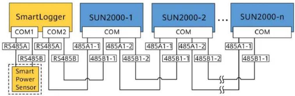
- SmartLogger networking
Figure 5-20 SmartLogger networking (the dashed box indicates optional components)
flowchart
graph TD
    A["SmartLogger"] --> B["COM1"]
    A --> C["COM2"]
    B --> D["RS485A"]
    C --> E["RS485A"]
    D --> F["RS485B"]
    E --> G["RS485B"]
    F --> H["Smart Power Sensor"]
    G --> I["485A1-1"]
    G --> J["485A1-2"]
    H --> K["485B1-1"]
    I --> L["485B1-2"]
    J --> M["485B1-1"]
    K --> N["485B1-2"]
    L --> O["..."]
    M --> P["485B1-1"]
    N --> Q["SUN2000-1"]
    O --> R["SUN2000-2"]
    P --> S["SUN2000-n"]
    Q --> T["COM"]
    R --> U["COM"]
    S --> V["COM"]
NO TE
- A maximum of 80 devices can connect to a single SmartLogger. You are advised to connect fewer than 30 devices to each RS485 route.
- If the SUN2000 is networked over the SmartLogger, it cannot connect to the Smart Dongle.
- A DTSU666-H smart power meter (provided by Huawei) is required to prevent backflow.
- To ensure the system response speed, it is recommended that the power meter be connected to one COM port.
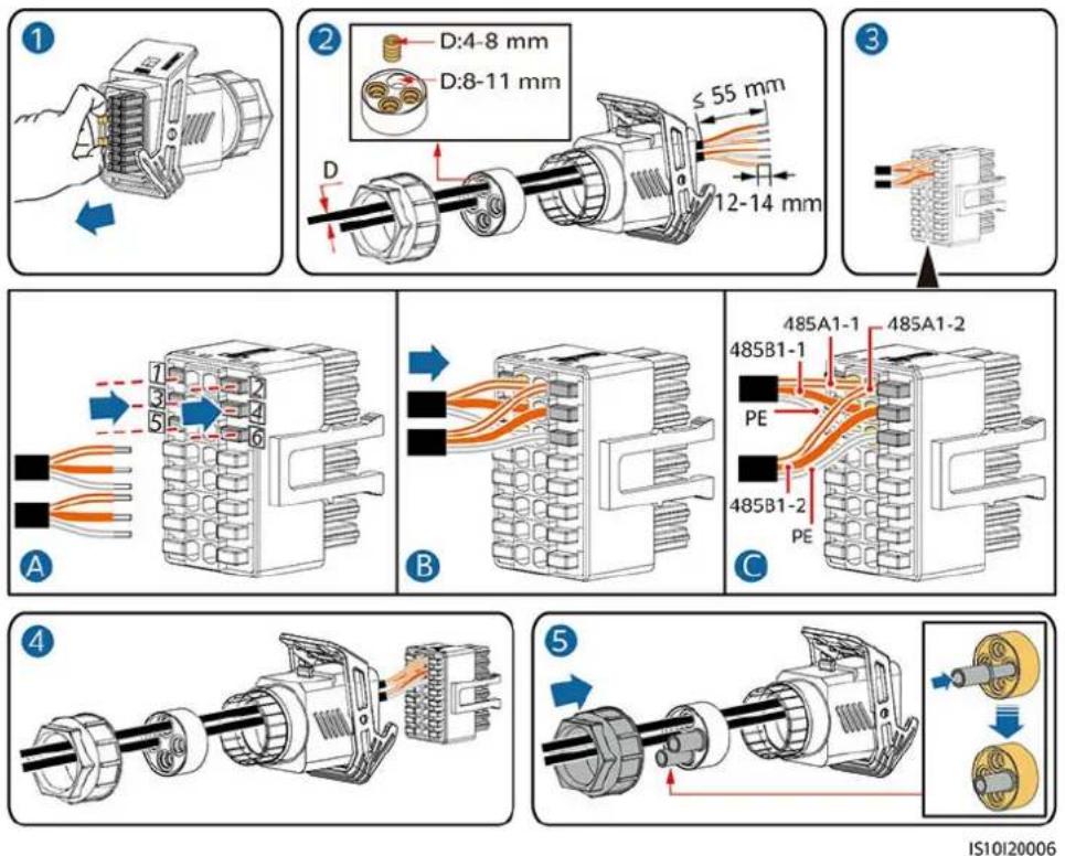
5.7.1 Connecting the RS485 Communications Cable (Inverter Cascading)
Procedure
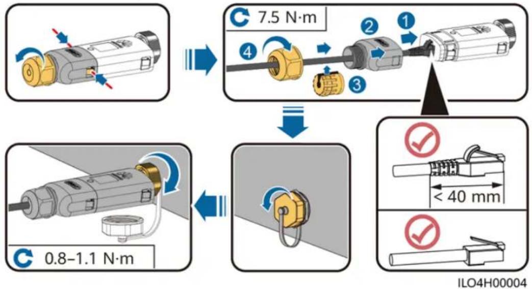
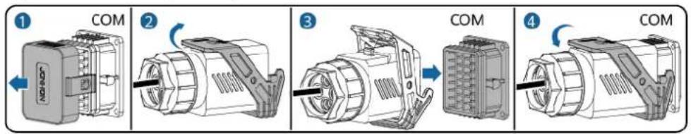
Step 1 Connect the signal cable to the signal cable connector.
Figure 5-21 Installing the cable
IS10I20006
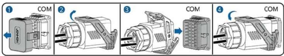
Step 2 Connect the signal cable connector to the COM port.
Figure 5-22 Securing the signal cable connector
IS10I20007
----End
5.7.2 Connecting the RS485 Communications Cable (Smart Power Sensor)
Cable Connection
The following figure shows the cable connections between the inverter and the Smart Power Sensor.
Figure 5-23 Cable connection (Three Phase Three Wire)
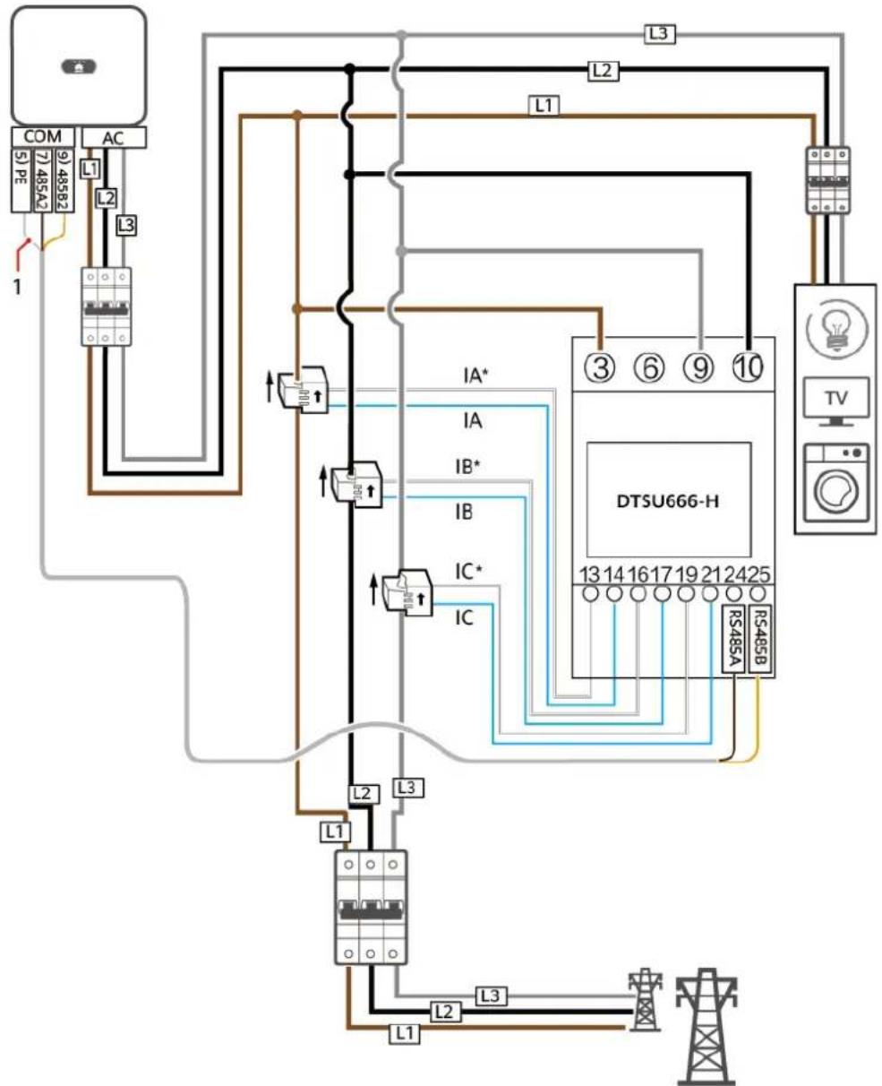
IH05N00005
Figure 5-24 Cable connection (Three Phase Four Wire)
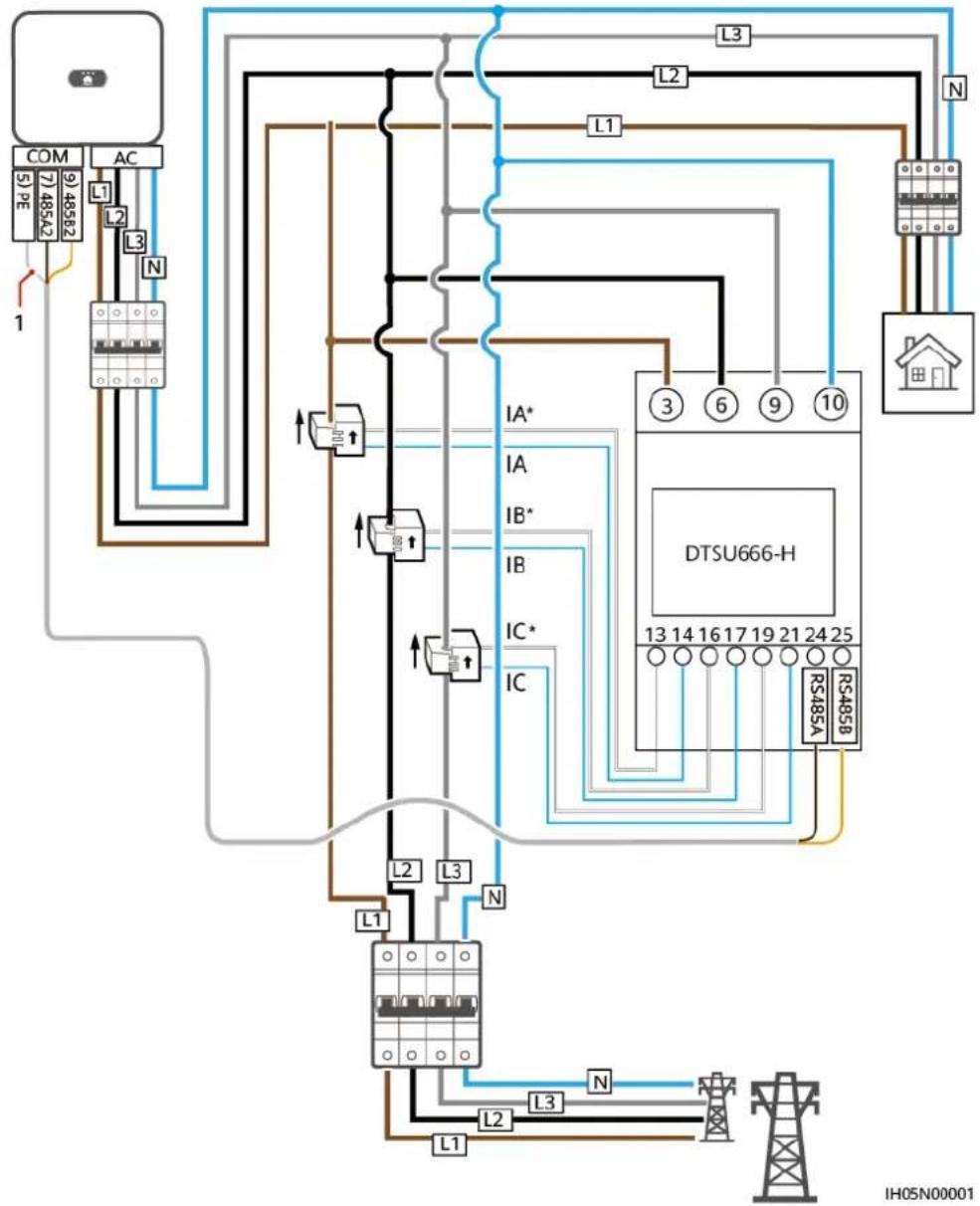
(1) Shielding layer of the signal cable

NO TE
For a three-phase three-wire system, you need to set the cable connection mode. Otherwise, the displayed voltage is incorrect.
Table 5-4
| Parameter | Note |
| nEt | Select the cable connection mode:0: n.34 indicates three-phase four-wire. 1: n.33 indicates three-phase three-wire. |
Procedure
Step 1 Connect the signal cable to the signal cable connector.
Figure 5-25 Installing the cable
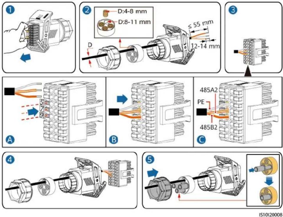
IS10I20008
Step 2 Connect the signal cable to the COM port.
Figure 5-26 Securing the signal cable connector
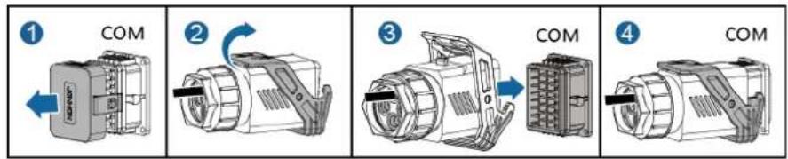
IS10I20007
----End
5.7.3 Connecting an RS485 Communications Cable (Between a Power Meter and a Battery)
Procedure
Step 1 Connect the signal cable to the signal cable connector.
Figure 5-27 Installing the cable
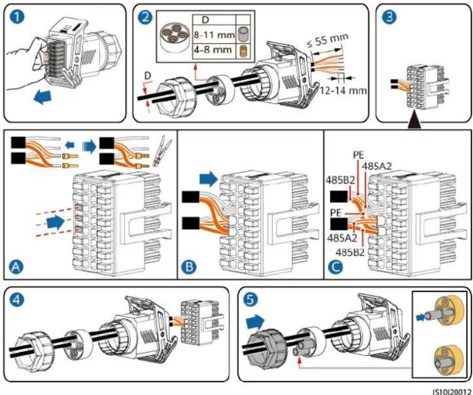
IS10I20012
Step 2 Connect the signal cable connector to the COM port.
Figure 5-28 Securing the signal cable connector
IS10I20007
----End
5.7.4 Connecting the Power Grid Scheduling Signal Cable
Cable Connection
The following figure shows the cable connections between the inverter and the Ripple Control Device.
Figure 5-29 Cable connection
Procedure
Step 1 Connect the signal cable to the signal cable connector.
Figure 5-30 Installing the cable
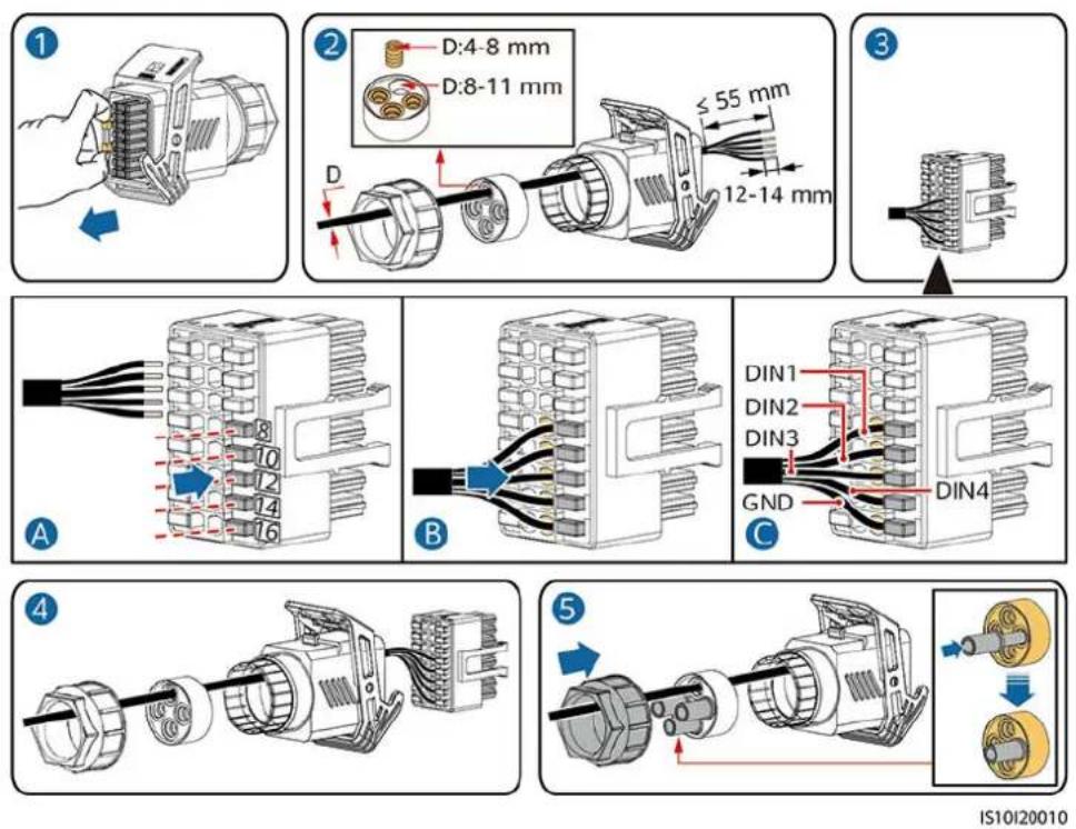
IS10I20010
Step 2 Connect the signal cable to the COM port.
Figure 5-31 Securing the signal cable connector
IS10I20007
----End
5.7.5 Connecting a Signal Cable to the Smart Backup Box
Procedure
Step 1 Connect the signal cable to the signal cable connector.
Figure 5-32 Installing the cable
Step 2 Connect the signal cable connector to the COM port.
Figure 5-33 Securing the signal cable connector
5.7.6 Connecting the NS Protection Signal Cable
Connecting the Inverter to the NS Protection Signal Cable
NO TE
- The NS protection function applies to areas in compliance with the VDE4105 standard, and the grid code needs to be set to VDE-AR-N-4105.
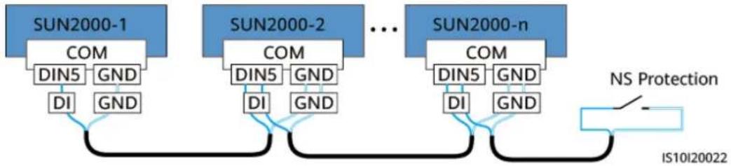
- The NS protection switch is connected to GND (pin 13) at one end and to DIN5 (pin 15) at the other end. The switch is turned off by default. When the switch is turned on, NS protection is triggered. Rapid shutdown and NS protection use the same pins, which are GND (pin 13) and DIN5 (pin 15). Therefore, you can use only one of the functions.
- The NS protection switch connection is the same for a single inverter and for cascaded inverters.
- Log in to the FusionSolar app as an installer, choose My > Device Commissioning, and connect to the WLAN hotspot of the SUN2000. Log in to the local commissioning system as an installer user, choose Settings > Feature parameters > Dry contact function, and set Dry contact function to NS protection.
Figure 5-34 Connecting cascaded inverters to the NS protection switch
flowchart
graph TD
    A["SUN2000-1"] --> B["COM"]
    B --> C["DIN5 GND"]
    C --> D["DI GND"]
    D --> E["..."]
    E --> F["SUN2000-2"]
    F --> G["COM"]
    G --> H["DIN5 GND"]
    H --> I["DI GND"]
    I --> J["..."]
    J --> K["SUN2000-n"]
    K --> L["COM"]
    L --> M["DIN5 GND"]
    M --> N["DI GND"]
    N --> O["..."]
    O --> P["NS Protection"]
    P --> Q["IS10I20022"]
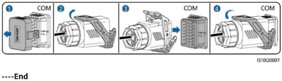
Step 1 Connect the signal cables of the cascaded inverters to the signal cable connectors.
Figure 5-35 Installing cables
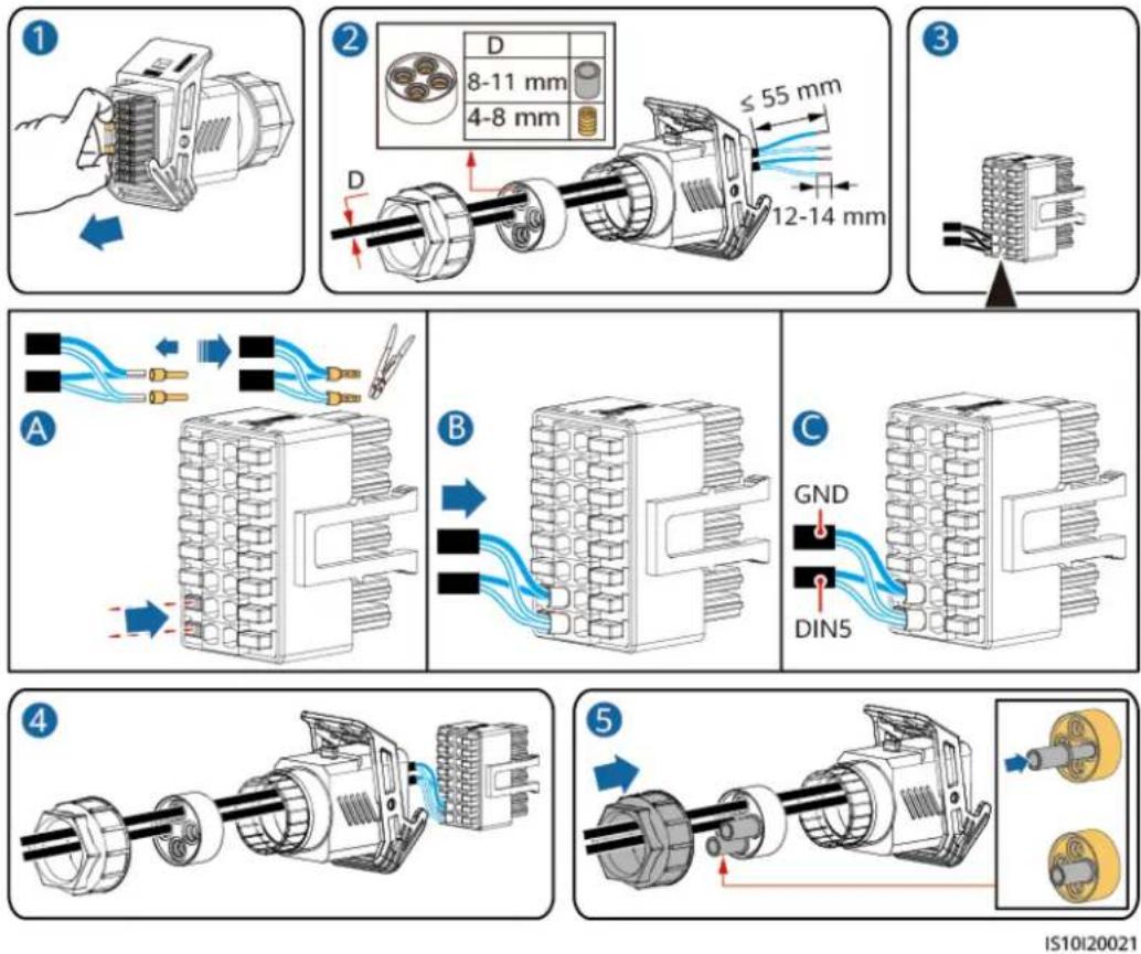
IS10I20021
Step 2 Connect the signal cable connectors to the COM ports.
Figure 5-36 Securing the signal cable connector
IS10I20007
----End
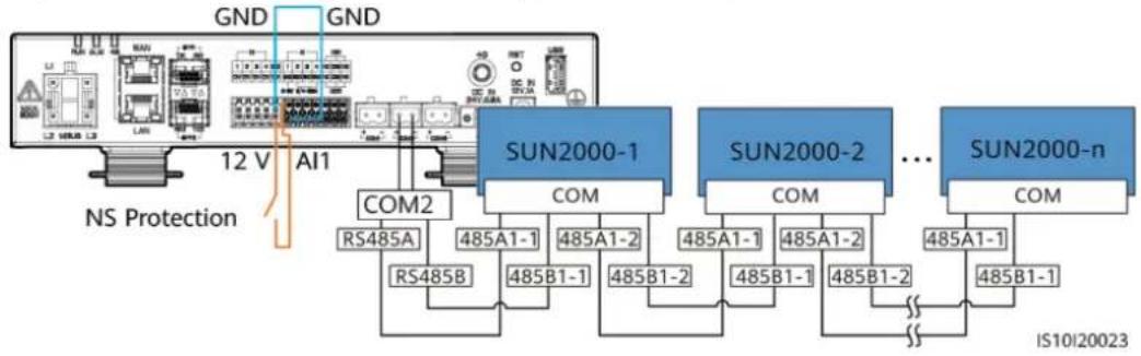
Setting NS Protection Remote Shutdown
NO TE
- The NS protection function is applicable to areas in compliance with the VDE4105 standard. To configure this function, choose Monitoring > Running Param. > Grid Parameters and set Grid code to VDE-AR-N-4105.
- The NS protection device is connected to the AI1 port and 12V power output port. The SmartLogger shuts down the inverter over the voltage change detected at the AI1 port. When the NS protection device is disconnected, the AI1 port voltage is 0 V, and the inverter shuts down. When the NS protection device is connected again, the AI1 port voltage is 12 V, and you need to start the inverter manually.
Figure 5-37 Connecting the SmartLogger to the NS protection switch
flowchart
graph TD
    A["Device"] -->|GND| B["AI1"]
    B --> C["NS Protection"]
    B --> D["SUN2000-1"]
    D --> E["COM2"]
    D --> F["SUN2000-2"]
    F --> G["COM"]
    F --> H["SUN2000-n"]
    H --> I["COM"]
    D --> J["RS485A"]
    D --> K["RS485B"]
    D --> L["485A1-1"]
    D --> M["485A1-2"]
    F --> N["485A1-1"]
    F --> O["485A1-2"]
    F --> P["485B1-1"]
    F --> Q["485B1-2"]
    H --> R["485A1-1"]
    H --> S["485A1-2"]
    H --> T["485B1-1"]
    H --> U["485B1-2"]
    H --> V["..."]
    H --> W["485A1-1"]
    H --> X["485B1-1"]
    style A fill:#f9f,stroke:#333
    style B fill:#ccf,stroke:#333
    style H fill:#cfc,stroke:#333
    style I fill:#fcc,stroke:#333
    style J fill:#cff,stroke:#333
    style K fill:#ffc,stroke:#333
    style L fill:#ffc,stroke:#333
    style M fill:#ffc,stroke:#333
    style N fill:#ffc,stroke:#333
    style O fill:#ffc,stroke:#333
    style P fill:#ffc,stroke:#333
    style Q fill:#ffc,stroke:#333
    style R fill:#ffc,stroke:#333
    style S fill:#ffc,stroke:#333
    style T fill:#ffc,stroke:#333
    style U fill:#ffc,stroke:#333
    style V fill:#ffc,stroke:#333
    style W fill:#ffc,stroke:#333
6 Commissioning
6.1 Checking Before Power-On
Table 6-1 Checklist
| No. | Item Acceptance Criterion | |
| 1 SUN2000 | installation The SUN2000 is | installed correctly and securely. |
| 2 Smart | Dongle The Smart Dongle is | stalled correctly and securely. |
| 3 Cable | routing The cables are routed pro | properly as required by the customer. |
| 4 Cable ties | Cable ties are secured evenly and no burr exists. | |
| 5 Reliable | grounding The PE cable is connected correctly and securely. | |
| 6 Switch | DC switches and all the switches connecting to the SUN2000 are OFF. | |
| 7 Cable | connection The AC output power cable, DC input power cables, battery cable, and signal cable are connected correctly and securely. | |
| 8 Unused | terminals and ports Unused terminals and ports are locked by watertight caps. | |
| 9 Installation environment | The installation space is proper, and the installation environment is clean and tidy. |
6.2 SUN2000 power-on
Important Notes
NO TICE
Before turning on the AC switch between the SUN2000 and the power grid, check that the AC voltage is within the specified range using a multimeter.
Procedure
Step 1 If a battery is connected, turn on the battery switch.
Step 2 Turn on the AC switch between the SUN2000 and the power grid.
NO TICE
If the DC is on and the AC is off, the SUN2000 reports a Grid Failure alarm. The SUN2000 starts normally only after the fault is automatically rectified.
Step 3 (Optional) Remove the locking screw from the DC switch.
Figure 6-1 Removing the locking screw from a DC switch
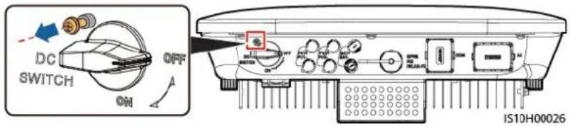
Step 4 Turn on the DC switch (if any) between the PV string and the SUN2000.
Step 5 Turn on the DC switch at the bottom of the SUN2000.
Step 6 Wait for about 1 minute and observe the LED indicators on the SUN2000 to check its running status.
Table 6-2 LED indicator description
| Category | Status Meaning | ||
Running indication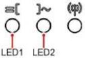 | LED1 LED2 N/A | ||
| Steady green Steady green The SUN2000 is operating in grid-tied mode. | |||
| Category Status | Meaning | |||
| Blinking green at long intervals (on for 1s and then off for 1s) | Off The DC is on and the | AC is off. | ||
| Blinking green at long intervals (on for 1s and then off for 1s) | Blinking green at long intervals (on for 1s and then off for 1s) | The DC is on, the AC is on, and the SUN2000 is not exporting power to the power grid. | ||
| Off Blinking green at long intervals (on for 1s and then off for 1s) | en at long intervals (on for 1s and then off for 1s) | The DC is off and the AC is on. | ||
| Steady orange Steady orange The SUN2000 is operating in the off-grid mode. | ||||
| Blinking orange slowly | Off The DC is on, and the SUN2000 has no output in the off-grid mode. | |||
| Blinking orange slowly | Blinking orange slowly The SUN2000 is operating in the overload in backup mode. | |||
| Off Off Both the DC and AC are off. | ||||
| Blinking red at short intervals (on for 0.2s and then off for 0.2s) | N/A There is a DC environmental alarm, such as an alarm indicating that High String Input Voltage, String Reverse Connection, or Low Insulation Resistance. | |||
| N/A Blinking red at short intervals (on for 0.2s and then off for 0.2s) | at short intervals (on for 0.2s and then off for 0.2s) | There is an AC environmental alarm, such as an alarm indicating Grid Undervoltage, Grid Overvoltage, Grid Overfrequency, or Grid Underfrequency. | ||
| Steady red Steady red Fault | ||||
| Communication indication(AB7A) (HYS4) [T357] | LED3 N/A | |||
| Blinking green at short intervals (on for 0.2s and then off for 0.2s) | Communication is in progress. (When a mobile phone is connected to the SUN2000, the indicator first indicates that the phone is connected to the SUN2000): blinks green at long intervals.) | |||
| Blinking green at long intervals (on for 1s and then off for 1s) | The mobile phone is connected to the SUN2000. | |||
| Off There is no communication. | ||||
| Device replacement indication | LED1 LED2 LED3 N/A | |||
| Steady red Steady | red Steady | red The SUN2000 hardware is faulty.The SUN2000 needs to be replaced. | ||
NO TE
If the off-grid load is overloaded, indicators LED1 and LED2 on the inverter blink orange slowly. Reduce the off-grid load power and manually clear the alarm or until the inverter is recovered. The inverter attempts to restart at an interval of 5 minutes. If the inverter fails to restart for three times, the interval changes to 2 hours. If the inverter is standby in off-grid mode, check the inverter alarms and rectify the fault.
Step 7 (Optional) Observe the LED indicator on the Smart Dongle to check its running status.
- WLAN-FE Smart Dongle
Figure 6-2 WLAN-FE Smart Dongle
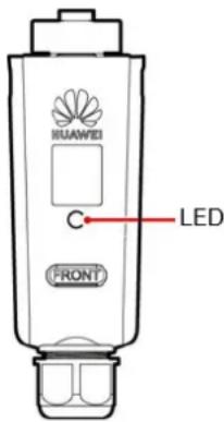
Table 6-3 Indicator description
| Indicators | Status Remarks Description | ||
| - | Off | Normal | The Smart Dongle is not secured or not powered on. |
| Yellow (blinking green and red simultaneously) | Steady on | The Smart Dongle is secured and powered on. | |
| Indicators Status | Remarks Description | ||
| Red Blinking at | short intervals (on for 0.2s and then off for 0.2s) | The parameters for connecting to the router are not set. | |
| Red Steady on | Abnormal The Smart | Dongle is | faulty. Replace the Smart Dongle. |
| Blinking red and green alternatively | Blinking at long intervals (on for 1s and then off for 1s) | Abnormal No communication with the SUN2000- Remove and then insert the Smart Dongle.- Check whether the SUN2000 matches the Smart Dongle.- Connect the Smart Dongle to another SUN2000.Check whether the Smart Dongle is faulty or the USB port of the SUN2000 is faulty. | |
| Green Blinking | at long intervals (on for 0.5s on and then off for 0.5s) | Normal Connecting to the router. | |
| Green Steady on | Connected to the | ||
| Green Blinking | at short intervals (on for 0.2s and then off for 0.2s) | ||
- 4G Smart Dongle
Table 6-4 Indicator description
| Indicators | Status Remarks Description | ||
| - | Off | Normal | The Smart Dongle is not secured or not powered on. |
| Indicators Status Remarks Description | |||
| Yellow (blinking green and red simultaneously) | Steady on Normal The Smart Dongle is secured and powered on. | ||
| Green The blinking interval is 2s. The indicator is on for 0.1s and then off for 1.9s alternately. | Normal Dialing (lasting for less than 1 minute) | ||
| Abnormal If the duration is longer than 1 minute, the 4G parameter settings are incorrect. Reset the parameters. | |||
| Blinking at long intervals (on for 1s and then off for 1s) | Normal The dialup is successful (lasting for less than 30s). | ||
| Abnormal If the duration is longer than 30s, the management system parameters are incorrectly set. Reset the parameters. | |||
| Steady on Normal Connected to the management system. | |||
| Blinking at short intervals (on for 0.2s and then off for 0.2s) | The SUN2000 communicates with the management system through the Smart Dongle. | ||
| Red Steady on Abnormal The Smart Dongle is faulty. Replace the Smart Dongle. | |||
| The Smart Dongle has no SIM card or the SIM card is in poor contact. Check whether the SIM card has been installed or is in good contact. If not, install the SIM card or remove and insert the SIM card. | |||
| Indicators Status | Remarks Description | ||
| Blinking at long intervals (on for 1s and then off for 1s) | The Smart Dongle fails to be connected to a management system because the SIM card has no signals, weak signal strength, or no traffic. If the Smart Dongle is reliably connected, check the SIM card signal through the SUN2000 app. If no signal is received or the signal strength is weak, contact the carrier. Check whether the tariff and traffic of the SIM card are normal. If not, recharge the SIM card or buy traffic. | ||
| Blinking red and green alternatively | Blinking at long intervals (on for 1s and then off for 1s) | No communication with the SUN2000- Remove and then insert the Smart Dongle.- Check whether the SUN2000 matches the Smart Dongle.- Connect the Smart Dongle to another SUN2000. Check whether the Smart Dongle is faulty or the USB port of the SUN2000 is faulty. | |
----End
7 Man-Machine Interaction
7.1 App Commissioning
7.1.1 Downloading the FusionSolar App
- Method 1: Access https://solar.huawei.com using the mobile phone browser and download the latest installation package.
Figure 7-1 Download Mode
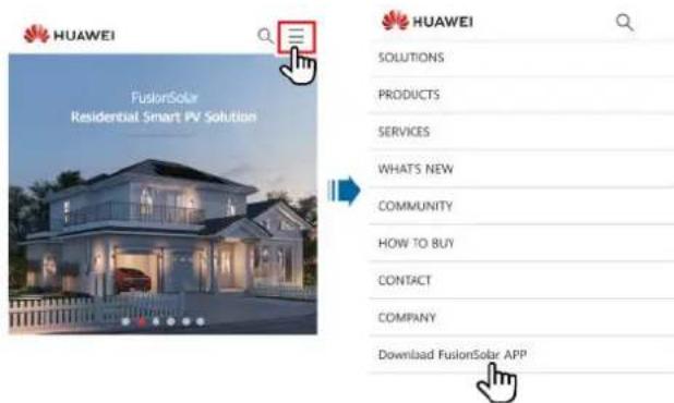
- Method 2: Search for FusionSolar on Huawei AppGallery and download the latest installation package.
- Method 3: Scan the following QR code and download the latest installation package.
Figure 7-2 QR code

FusionSolar
7.1.2 (Optional) Registering an Installer Account
NO TE
- If you have an installer account, skip this step.
- You can register an account only using a mobile phone only in China.
- The mobile number or email address used for registration is the user name for logging in to the FusionSolar app.
Create the first installer account and create a domain named after the company name.
Figure 7-3 Creating the first installer account
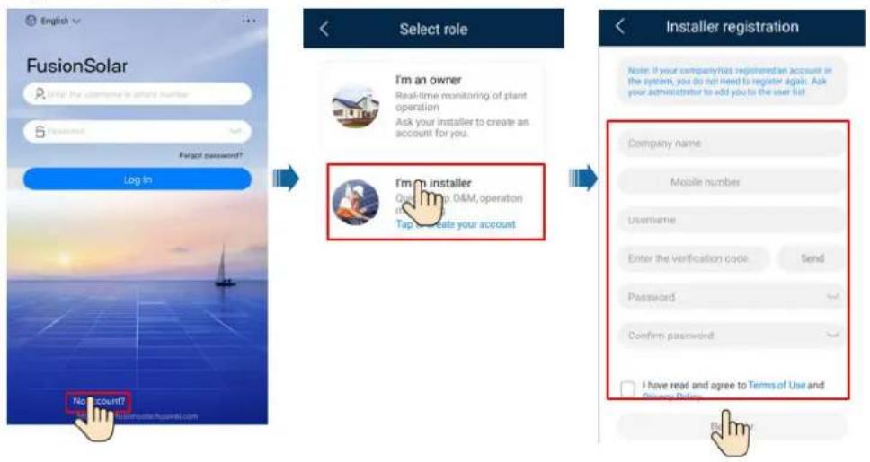
NO TICE
To create multiple installer accounts for a company, log in to the FusionSolar app and tap Add User to create an installer account.
Figure 7-4 Creating multiple installer accounts for the same company
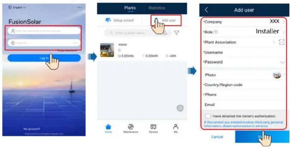
7.1.3 Creating a PV Plant and a User
Figure 7-5 Creating a PV plant and a user
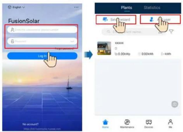

NO TE
For details about how to use the site deployment wizard, see FusionSolar App Quick Guide. During the FusionSolar app upgrade, scan the QR code to download the corresponding quick guide according to the downloaded app version.


7.1.4 (Optional) Setting the Physical Layout of the Smart PV Optimizers

NO TE
- If smart PV optimizers are configured for PV strings, ensure that the smart PV optimizers have been successfully connected to the SUN2000 before performing the operations in this section.
- Check that the SN labels of smart PV optimizers are correctly attached to the physical layout template.
- Take and save a photo of the physical layout template. Keep your phone parallel to the template and take a photo in landscape mode. Ensure that the four positioning points in the corners are in the frame. Ensure that each QR code is attached within the frame.
- For details about the physical layout of smart PV optimizers, see FusionSolar App Quick Guide. During the FusionSolar app upgrade, scan the QR code to download the corresponding quick guide according to the downloaded app version.

Scenario 1: Setting on the FusionSolar Server Side (Solar Inverter Connected to the Management System)
Step 1 Log in to the FusionSolar app and tap the plant name on the Home screen to access the plant screen. Select Layout, tap, and upload the physical layout template photo as prompted.
Figure 7-6 Uploading the physical layout template photo (App)
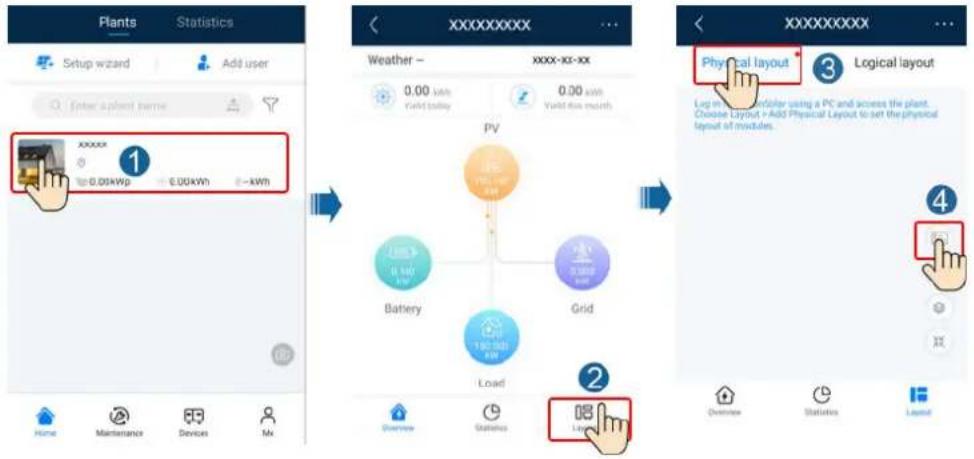
NO TE
You can also upload the physical layout template photo on the WebUI as follows: Log in to https://intl.fusionsolar.huawei.com to access the WebUI of the FusionSolar Smart PV Management System. On the Home page, click the plant name to go to the plant page. Choose Layout, click Click to Upload, and upload the physical layout template photo.
Figure 7-7 Uploading the physical layout template photo (WebUI)
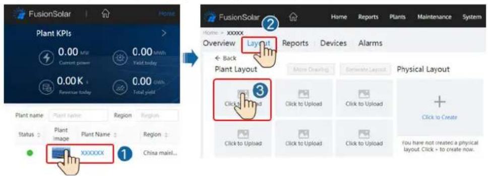
Step 2 Log in to https://intl.fusionsolar.huawei.com to access the WebUI of the FusionSolar Smart PV Management System. On the Home page, click the plant name to go to the plant page. Select Layout. Choose Generate layout, and create a physical layout as prompted. You can also manually create a physical location layout.
Figure 7-8 Physical layout design of PV modules
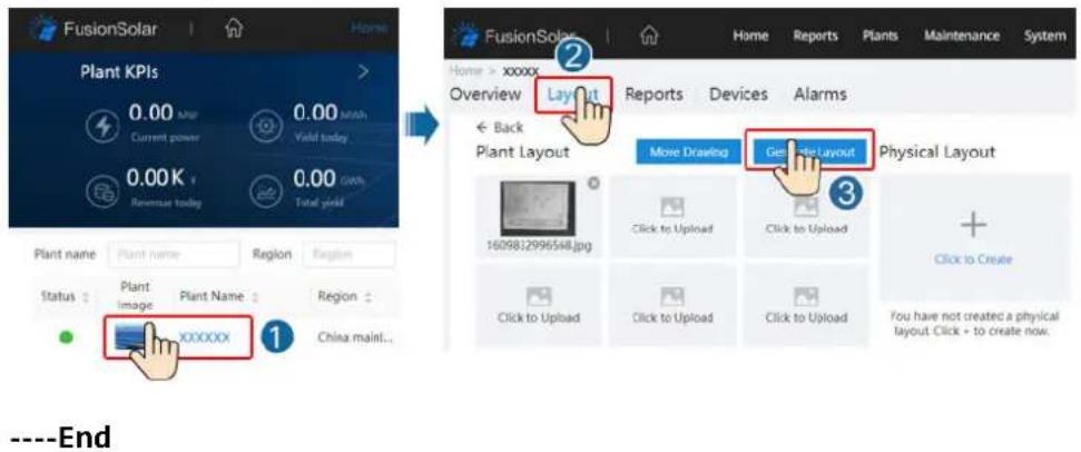
Scenario 2: Setting on the Solar Inverter Side (Solar Inverter Not Connected to the Management System)
Step 1 Access the Device Commissioning screen on the FusionSolar app to set the physical layout of Smart PV Optimizers.
-
Log in to the FusionSolar app. On the Device Commissioning screen, choose Maintenance > Optimizer layout. The Optimizer layout screen is displayed.
-
Tap the blank area. The Identify image and Add PV modules buttons are displayed. You can use either of the following methods to perform operations as prompted:
- Method 1: Tap Identify image and upload the physical layout template photo to complete the optimizer layout. (The optimizers that fail to be identified need to be manually bound.)
- Method 2: Tap Add PV modules to manually add PV modules and bind the optimizers to the PV modules.
Figure 7-9 Physical layout design of PV modules
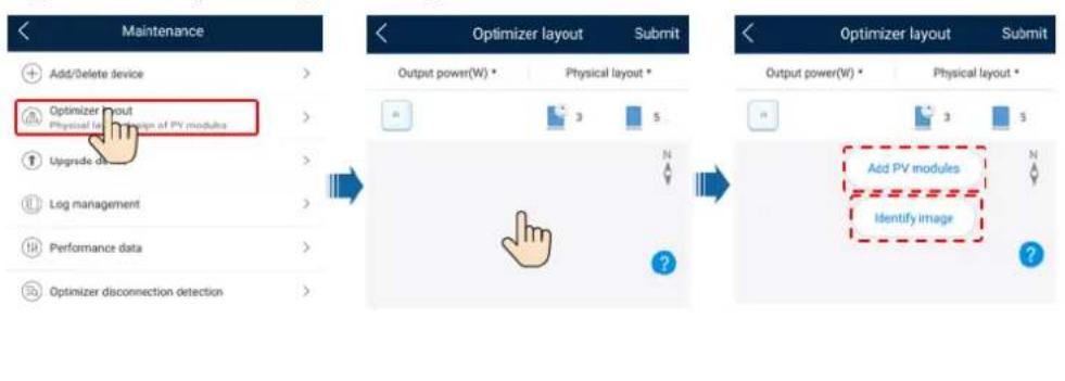
7.1.5 Detect optimizer disconnection
Log in to the FusionSolar app, choose Device Commissioning > Maintenance > Optimizer disconnection detection, tap the detection button to detect the optimizer disconnection, and rectify the fault based on the detection result.
Figure 7-10 Detect optimizer disconnection
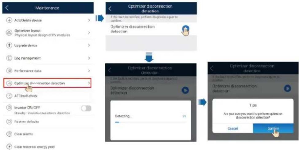
flowchart
graph TD
    A["Add/Delete device"] --> B["Optimizer disconnection detection"]
    C["Optimizer layout\nPhysical layout design of PV modules"] --> B
    D["Upgrade device"] --> B
    E["Log management"] --> B
    F["Performance data"] --> B
    G["Optimizer disconnection detection"] --> H["Optimize disconnection detection"]
    I["AFC1sell-check"] --> H
    J["Invater ON/OFF\nStandby insulation resistance detection"] --> H
    K["Restore defaults"] --> H
    L["Clear alarms"] --> H
    M["Clear historical energy yield"] --> H
    N["Optimize disconnection detection"] --> O["Optimize disconnection detection"]
    P["Optimize disconnection detection"] --> Q["Tips\nAre you sure you want to perform optimizer disconnection detection?"]
    R["Cancel"] --> S["Confirm"]
7.2 Parameters Settings
Go to the Device Commissioning screen and set SUN2000 parameters. For details about entering the Device Commissioning screen, see B Device Commissioning.
To set more parameters, tap Settings. For details about the parameters, see the FusionSolar APP and SUN2000 App User Manual. You can also scan the QR code to obtain the document.

7.2.1 Energy Control
On the home screen, tap Power adjustment to perform the corresponding operation.
Figure 7-11 Energy control
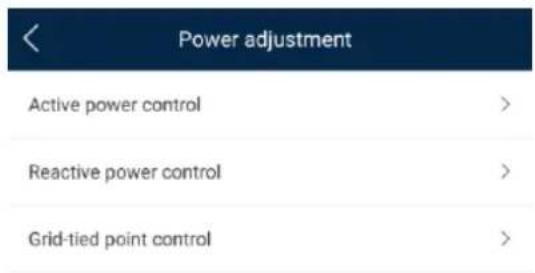
7.2.1.1 Grid-tied Point Control
Function
Limits or reduces the output power of the PV power system to ensure that the output power is within the power deviation limit.
Procedure
Step 1 On the home screen, choose Power adjustment > Grid-tied point control.
Figure 7-12 Grid-tied point control
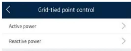
Table 7-1 Grid-tied point control
| Parameter Name | Description | ||
| Active power | Unlimited - If this parameter is set to Unlimited | the output power of the SUN2000 is not limited and the SUN2000 can connect to the power grid at the rated power. | |
| Grid connection with zero power | Closed-loop controller ● | If multiple SUN2000s are cascaded, set this parameter to SDongle/SmartLogger.● If there is only one SUN2000, set this parameter to Inverter. | |
| Limitation mode Total power indicates export limitation of the total power at the grid-tied point. | |||
| Power adjustment period | Specifies the shortest interval for a single anti-backfeeding adjustment. | ||
| Power control hysteresis | Specifies the dead zone for adjusting the SUN2000 output power. If the power fluctuation is within the power control hysteresis, the power is not adjusted. | ||
| Parameter Name Description | |||
| Active power output limit for fail-safe | Specifies the derating value of the SUN2000 active power by percentage. If the Smart Dongle does not detect any meter data or the communication between the Smart Dongle and the SUN2000 is disconnected, the Smart Dongle delivers the derating value of the SUN2000 active power by percentage. | ||
| Communication disconnection fail-safe | In the SUN2000 anti-backfeeding scenario, if this parameter is set to Enable, the SUN2000 will derate according to the active power derating percentage when the communication between the SUN2000 and the Smart Dongle is disconnected for a period longer than Communication disconnection detection time. | ||
| Communication disconnection detection time | Specifies the time for determining the communication disconnection between the SUN2000 and the Dongle.This parameter is displayed when Communication disconnection fail-safe is set to Enable. | ||
| Grid connection with limited power (kW) | Closed-loop controller ● | If multiple SUN2000s are cascaded, set this parameter to SDongle/SmartLogger.● If there is only one SUN2000, set this parameter to Inverter. | |
| Limitation mode Total power indicates export limitation of the total power at the grid-tied point. | |||
| Maximum grid feed-in power | Specifies the maximum active power transmitted from the grid-tied point to the power grid. | ||
| Power adjustment period | Specifies the shortest interval for a single anti-backfeeding adjustment. | ||
| Power control hysteresis | Specifies the dead zone for adjusting the SUN2000 output power. If the power fluctuation is within the power control hysteresis, the power is not adjusted. | ||
| Power control hysteresis | Specifies the dead zone for adjusting the SUN2000 output power. If the power fluctuation is within the power control hysteresis, the power is not adjusted. | ||
| Active power output limit for fail-safe | Specifies the derating value of the SUN2000 active power by percentage. If the Smart Dongle does not detect any meter data or the communication between the Smart Dongle and the SUN2000 is disconnected, the Smart Dongle delivers the derating value of the SUN2000 active power by percentage. | ||
| Communication disconnection fail-safe | In the SUN2000 anti-backfeeding scenario, if this parameter is set to Enable, the SUN2000 will derate according to the active power derating percentage when the communication between the SUN2000 and the Smart Dongle is disconnected for a period longer than Communication disconnection detection time. | ||
| Communication disconnection detection time | Specifies the time for determining the communication disconnection between the SUN2000 and the Dongle.This parameter is displayed when Communication disconnection fail-safe is set to Enable. | ||
----End
7.2.1.2 Battery Control
Prerequisites
The screenshots in this chapter are taken in the SUN2000 3.2.00.011 app. The app is being updated. The actual screens may vary.
Function
When the inverter connects to a battery, add the battery and set battery parameters.
Adding a Battery
To add a battery, choose Maintenance > Subdevice management on the home screen.
Figure 7-13 Adding a battery
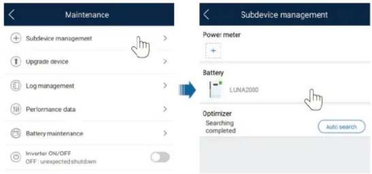
Parameters Settings
On the home screen, choose Power adjustment > Battery control, and set the battery parameters and working mode.
Figure 7-14 Battery control parameter setting
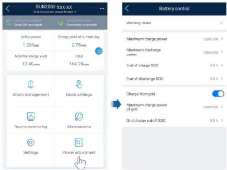
| Parameter | Description Value Range | |
| Working mode For details, see the description on the app screen. | Maximum self-consumptionTime-of-useFully fed to grid | |
| Parameter Description | Value Range | |
| Maximum charge power (kW) | Retain this parameter to the maximum charge power. Additional configuration is not required. | Charge: [0, Maximum charge power] |
| Maximum discharge power (kW) | Retain this parameter to the maximum discharge power. Additional configuration is not required. | Discharge: [0, Maximum discharge power] |
| End-of-charge SOC (%) | Set the charge cutoff capacity. 90%-100% | |
| End-of-discharge SOC (%) | Set the discharge cutoff capacity. | 0%-20% (When no PV module is configured or the PV modules have no voltage for 24 hours, the minimum value is 15%.) |
| Charge from grid If Charge from grid function is disabled by default, comply with the grid charge requirements stipulated in local laws and regulations when this function is enabled. | DisableEnable | |
| Grid charge cutoff SOC | Set the grid charge cutoff SOC. [20%, 100%] | |
7.2.2 AFCI
Function
If PV modules or cables are not properly connected or damaged, electric arcs may occur, which may cause fire. Huawei SUN2000s provide unique arc detection in compliance with UL 1699B-2018 to ensure the safety of users' lives and property.
This function is enabled by default. The SUN2000 automatically detects arc faults. To disable this function, log in to the FusionSolar app, enter the Device Commissioning screen, choose Settings > Feature parameters, and disable AFCI.
Clearing Alarms
The AFCI function involves the DC arc fault alarm.
The SUN2000 has the AFCI alarm automatic clearance mechanism. If an alarm is triggered for less than five times within 24 hours, the SUN2000 automatically clears the alarm. If the alarm is triggered for five times or more within 24 hours, the SUN2000 locks for protection. You need to manually clear the alarm on the SUN2000 so that it can work properly.
You can manually clear the alarm as follows:
• Method 1: FusionSolar App
Log in to the FusionSolar app and choose My > Device Commissioning. On the Device Commissioning screen, connect and log in to the SUN2000 that generates the AFCI alarm, tap Alarm management, and tap Clear on the right of the DC arc fault alarm to clear the alarm.
Figure 7-15 Alarm management
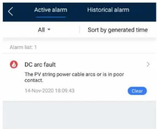
• Method 2: FusionSolar Smart PV Management System
Log in to the FusionSolar Smart PV Management System using a non-owner account, choose Maintenance > Alarm Management, select the DC arc fault alarm, and click Clear to clear the alarm.
Figure 7-16 Clearing alarms
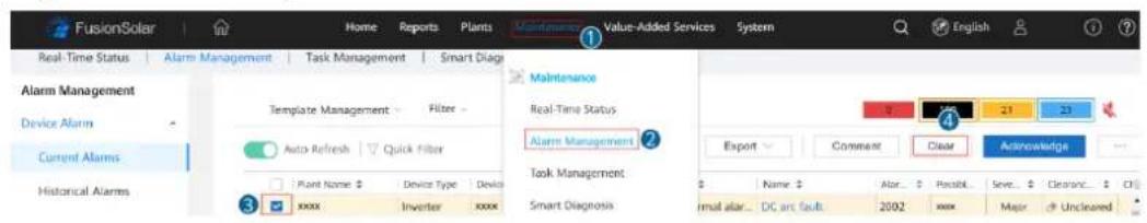
Switch to the owner account with PV plant management rights. On the home page, click the PV plant name to go to the PV plant page, and click OK as prompted to clear the alarm.
7.2.3 IPS Check (for Italy CEI0-21 Grid Code Only)
Function
The Italy CEI0-21 grid code requires an IPS check for the SUN2000. During the self-check, the SUN2000 checks the protection threshold and protection time of the maximum voltage over 10 min (59.S1), maximum overvoltage (59.S2), minimum undervoltage (27.S1), minimum undervoltage (27.S2), maximum overfrequency (81.S1), maximum overfrequency (81.S2), minimum underfrequency (81.S), and minimum underfrequency (81.S2).
Procedure
Step 1 On the home screen, choose Maintenance > IPS test to access the IPS test screen.
Step 2 Tap Start to start an IPS test. The SUN2000 detects maximum voltage over 10 min (59.S1), maximum overvoltage (59.S2), minimum undervoltage (27.S1), minimum undervoltage (27.S2), maximum overfrequency (81.S1), maximum overfrequency (81.S2), and minimum underfrequency (81.S1), and minimum underfrequency (81.S2).
Figure 7-17 IPS test
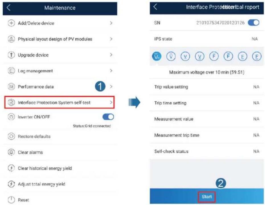
Table 7-2 IPS test type
| IPS Test Type | Description |
| Maximum voltage over 10 min (59.S1) | The default maximum voltage over 10 min protection threshold is 253 V (1.10 Vn), and the default protection time threshold is 3s. |
| Maximum overvoltage (59.S2) | The default overvoltage protection threshold is 264.5 V (1.15 Vn), and the default protection time threshold is 0.2s. |
| Minimum undervoltage (27.S1) | The default undervoltage protection threshold is 195.5 V (0.85 Vn), and the default protection time threshold is 1.5s. |
| Minimum undervoltage (27.S2) | The default undervoltage protection threshold is 34.5 V (0.15 Vn), and the default protection time threshold is 0.2s. |
| IPS Test Type Description | |
| Maximum overfrequency (81.S1) | The default overfrequency protection threshold is 50.2 Hz, and the default protection time threshold is 0.1s. |
| Maximum overfrequency (81.S2) | The default overfrequency protection threshold is 51.5 Hz, and the default protection time threshold is 0.1s. |
| Minimum underfrequency (81.S1) | The default underfrequency protection threshold is 49.8 Hz, and the default protection time threshold is 0.1s. |
| Minimum underfrequency (81.S2) | The default underfrequency protection threshold is 47.5 Hz, and the default protection time threshold is 0.1s. |
Step 3 After the IPS test is complete, IPS State is displayed as IPS state success. Tap Historical report in the upper right corner of the screen to view the IPS check report.
----End
7.3 SmartLogger Networking Scenario
See the Distributed PV Plants Connecting to Huawei Hosting Cloud Quick Guide (Distributed Inverters + SmartLogger1000A + RS485 Networking) and PV Plants Connecting to Huawei Hosting Cloud Quick Guide (Inverters + SmartLogger3000 + RS485 Networking). You can scan the QR code to obtain it.
Figure 7-18 SmartLogger1000A

Figure 7-19 SmartLogger3000

8 Maintenance
8.1 SUN2000 Power-Off
Important Notes
WARNING
- After the SUN2000 powers off, the remaining electricity and heat may still cause electric shocks and body burns. Therefore, put on protective gloves and begin operating the SUN2000 five minutes after the power-off.
- Before maintaining the optimizer and PV string, turn off the AC switch and DC switch. Otherwise, electric shocks may occur as the PV string is energized.
Procedure
Step 1 Turn off the AC switch between the SUN2000 and the power grid.
Step 2 Turn off the DC switch at the bottom of the SUN2000.
Step 3 (Optional) Install the locking screw beside the DC switch.
Figure 8-1 Installing the locking screw for the DC switch
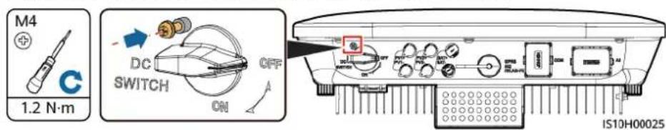
Step 4 If there is a DC switch between the inverter and PV string, turn off the DC switch.
Step 5 (Optional) Turn off the battery switch between the SUN2000 and batteries.
---End
8.2 Routine Maintenance
To ensure that the SUN2000 can operate properly for a long term, you are advised to perform routine maintenance on it as described in this chapter.

CA UTION
Before cleaning the system, connecting cables, and maintaining the grounding reliability, power off the system.
Table 8-1 Maintenance list
| Check Detail Check | Method Maintenance Interval | |
| System cleanliness | Check the heat sink for foreign matter or the overall health of the SUN2000. | Annual or every time an abnormality is detected |
| System running status | Check the SUN2000 for damage or deformation. | Annual |
| Electrical connections | Cables are securely connected.Cables are intact, in particular, the parts touching the metallic surface are not scratched. | The first inspection is 6 months after the initial commissioning. From then on, the interval can be 6 to 12 months. |
| Grounding reliability | Check whether the ground terminal and ground cable are securely connected. | Annual |
| Sealing Check whether | her all terminals and ports are properly sealed. | Annual |
8.3 Troubleshooting
Alarm severities are defined as follows:
- Major: The SUN2000 is faulty. As a result, the output power decreases or the grid-tied power generation is stopped.
- Minor: Some components are faulty without affecting the grid-tied power generation.
- Warning: The SUN2000 works properly. The output power decreases or some authorization functions fail due to external factors.
Table 8-2 Common fault alarm list
| ID Name | Severity Cause Solution | |||
| 2001 High | string input voltage | Major The | PV array is not properly configured. Excessive PV modules are connected in series to the PV string; therefore the PV string open-circuit voltage exceeds the maximum SUN2000 operating voltage.Cause ID 1 or 2: PV strings 1 and 2 | Reduce the number of PV modules connected in series to the PV string until the PV string open-circuit voltage is less than or equal to the maximum SUN2000 operating voltage. After the PV string configuration is corrected, the alarm disappears. |
| 2002 DC arc fault | Major The | PV string power cables arc or are in poor contact.Cause ID 1 = PV1 and PV2Cause ID 2 = PV3 and PV4 | Check whether the PV string cables arc or are in poor contact. | |
| 2003 DC arc fault | Major The | PV string power cables arc or are in poor contact.Cause ID 1 = PV1Cause ID 2 = PV2 | Check whether the PV string cables arc or are in poor contact. | |
| 2011 String reverse connection | Major The | PV string polarity is reversed.Cause ID 1 = PV1Cause ID 2 = PV2 | Check whether the PV string is reversely connected to the SUN2000. If so, wait until the PV string current decreases to below 0.5 A. Then, turn off the DC switch and correct the PV string polarity. | |
| 2012 String current backfeed | Warning The | The number of PV modules connected in series to the PV string is insufficient. As a result, the end voltage is lower than that of other strings.Cause ID 1 = PV1Cause ID 2 = PV2 | 1. Check whether the number of PV modules connected in series to this PV string is less than that of the other PV strings connected in parallel. If so, wait until the PV string current decreases to below 0.5 A. Then, turn off the DC switch and adjust the number of PV modules in the PV string.2. Check whether the PV string is shaded.3. Check whether the open-circuit voltage of the PV string is abnormal. | |
| ID Name | Severity Cause Solution | |||
| 2021 AFCI | self-check failure | Major Cause ID = 1, 2The AFCI self-check fails. | Turn off the AC output switch and DC input switch, and then turn them on after 5 minutes. If the alarm persists, contact your dealer or Huawei technical support. | |
| 2031 Phase | wire short-circuited to PE | Major Cause ID = 1The impedance of the output phase wire to PE is low or the output phase wire is short-circuited to PE. | Check the impedance of the output phase wire to PE, locate the position with low impedance, and rectify the fault. | |
| 2032 Grid loss | Major Cause ID = 1 | Power grid outage occurs.The AC circuit is disconnected or the AC switch is off. | The alarm is cleared automatically after the power grid recovers.Check whether the AC circuit is disconnected or the AC switch is off. | |
| 2033 Grid | undervoltage | Major Cause ID = 1The grid voltage is below the lower threshold or the low-voltage duration has lasted for more than the value specified by low voltage ride-through (LVRT). | If the alarm occurs occasionally, the power grid may be abnormal temporarily. The SUN2000 automatically recovers after detecting that the power grid becomes normal.If the alarm persists, check whether the power grid voltage is within the acceptable range. If not, contact the local power operator. If yes, modify the grid undervoltage protection threshold through the mobile app, SmartLogger, or network management system (NMS) with the consent of the local power operator.If the alarm persists for a long time, check the connection between the AC circuit breaker and the output power cable. | |
| 2034 Grid | overvolta ge | Major Cause ID = 1The grid voltage exceeds the upper threshold or the high voltage duration has lasted for more than the value specified by high voltage ride-through (HVRT). | 1. If the alarm occurs occasionally, the power grid may be abnormal temporarily. The SUN2000 automatically recovers after detecting that the power grid becomes normal.2. If the alarm persists, check whether the power grid voltage is within the acceptable range. If not, contact the local power operator. If yes, modify the grid overvoltage protection threshold through the mobile app, SmartLogger, or NMS with the consent of the local power operator.3. Check whether the peak voltage of the power grid is too high. If the alarm persists and cannot be rectified for a long time, contact the power operator. | |
| 2035 | Grid volt. Imbalance | Major Cause ID = 1The difference between grid phase voltages exceeds the upper threshold. | 1. If the alarm occurs occasionally, the power grid may be abnormal temporarily. The SUN2000 automatically recovers after detecting that the power grid becomes normal.2. If the alarm persists, check whether the power grid voltage is within the acceptable range. If not, contact the local power operator.3. If the alarm lasts for a long time, check the AC output power cable connection.4. If the AC output power cable is correctly connected, yet the alarm persists and affects the energy yield of the PV plant, contact the local power operator. | |
| 2036 Grid | overfrequency | Major Cause ID = 1Power grid exception: The actual power grid frequency is higher than the requirements for the local power grid code. | 1. If the alarm occurs occasionally, the power grid may be abnormal temporarily. The SUN2000 automatically recovers after detecting that the power grid becomes normal.2. If the alarm persists, check whether the power grid frequency is within the acceptable range. If not, contact the local power operator. If yes, modify the grid overfrequency protection threshold through the app, SmartLogger, or NMS with the consent of the local power operator. | |
| 2037 Grid | underfrequency | Major Cause ID = 1Power grid exception: The actual power grid frequency is lower than the requirements for the local power grid code. | 1. If the alarm occurs occasionally, the power grid may be abnormal temporarily. The SUN2000 automatically recovers after detecting that the power grid becomes normal.2. If the alarm persists, check whether the power grid frequency is within the acceptable range. If not, contact the local power operator. If yes, modify the grid underfrequency protection threshold through the app, SmartLogger, or NMS with the consent of the local power operator. | |
| 2038 Unstable grid frequency | Major Cause ID = 1Power grid exception: The actual change rate of the power grid frequency does not meet the requirements for the local power grid code. | 1. If the alarm occurs occasionally, the power grid may be abnormal temporarily. The SUN2000 automatically recovers after detecting that the power grid becomes normal.2. If the alarm persists, check whether the power grid frequency is within the acceptable range. If not, contact the local power operator. | ||
| 2039 Output overcurrent | Major Cause ID = 1The power grid voltage drops dramatically or the power grid is short-circuited. As a result, the SUN2000 transient output current exceeds the upper threshold, and protection is triggered. | 1. The SUN2000 monitors its external operating conditions in real time and automatically recovers after the fault is rectified.2. If the alarm persists and affects the energy yield of the power plant, check whether the output is short-circuited. If the fault persists, contact your dealer or Huawei technical support. | ||
| 2040 Output DC component overhigh | Major Cause ID = 1The DC component in the power grid current exceeds the upper threshold. | 1. The SUN2000 monitors its external operating conditions in real time and automatically recovers after the fault is rectified.2. If the alarm persists, contact your dealer or Huawei technical support. | ||
| 2051 Abnormal residual current | Major Cause ID = 1The input-to-ground insulation impedance has decreased during the SUN2000 operation. | 1. If the alarm occurs accidentally, the external power cable may be abnormal temporarily. The SUN2000 automatically recovers after the fault is rectified.2. If the alarm persists or lasts a long time, check whether the impedance between the PV string and ground is too low. | ||
| 2061 Abnormal grounding | Major Cause ID = 1The neutral wire or PE cable of the inverter is not connected.The output mode set for the inverter is inconsistent with the cable connection mode. | Power off the inverter (turn off the AC output switch and DC input switch, and wait for a period of time. For details about the wait time, see the description on the device safety warning label), and then perform the following operations:Check whether the PE cable for the inverter is connected properly.If the inverter is connected to a TN power grid, check whether the neutral wire is properly connected and whether the voltage of the neutral wire to ground is normal.After the inverter is powered on, check whether the output mode set for the inverter is consistent with the output cable connection mode. | ||
| ID Name | Severity Cause | Solution | ||
| 2062 Low | insulation resistance | Major Cause ID = 1A short circuit exists between the PV array and the ground.The PV array is in a moist environment and the circuit is not well insulated to the ground. | 1. Check the impedance between the PV array output and the ground. If a short circuit occurs or the insulation is insufficient, rectify the fault.2. Check whether the PE cable of the SUN2000 is correctly connected.3. If you have confirmed that the impedance is lower than the specified protection threshold in a cloudy or rainy environment, log in to the app, SmartLogger, or NMS and set theInsulation resistance protection threshold.For details about how to query the low insulation resistance alarm, seeHUAWEI SUN2000-5-10KTL-M1 Inverter Low Insulation Resistance Fault Indication Guide. | |
| 2063 | Cabinet overtemperature | Minor Cause ID = 1The SUN2000 is installed in a place with poor ventilation.The ambient temperature exceeds the upper threshold.The SUN2000 is not operating properly. | Check the ventilation and ambient temperature at the SUN2000 installation position.If the ventilation is poor or the ambient temperature exceeds the upper threshold, improve the ventilation and heat dissipation.If the ventilation and ambient temperature are normal, contact your dealer or Huawei technical support. | |
| 2064 Equipment | Equipment fault | Major Cause ID = 1–12An unrecoverable fault occurs on a circuit inside the SUN2000. | Turn off the AC output switch and DC input switch, and then turn them on after 5 minutes. If the alarm persists, contact your dealer or Huawei technical support. | |
| ID Name | Severity Cause Solution | |||
| 2065 Upgrade | failed or version mismatch | Minor Cause ID = 1-6The upgrade is not completed normally. | Perform an upgrade again.If the upgrade fails several times, contact your dealer or Huawei technical support. | |
| 2068 Battery abnormal | Minor Cause ID = 1-4The battery is faulty.The battery is disconnected.The battery switch trips when the inverter is operating. | If the fault indicator on the battery is steady on or blinking, contact the battery dealer.Check whether the battery enabling, power, and communications cable connections are correct, and whether the communications parameters are consistent with the RS485 configurations of the inverter.Check whether the battery auxiliary power switch is turned on. | ||
| 61440 Faulty monitoring unit | Minor Cause ID = 1The flash memory is insufficient.The flash memory has bad sectors. | Turn off the AC output switch and DC input switch, and then turn them on after 5 minutes. If the alarm persists, replace the monitoring board or contact your dealer or Huawei technical support. | ||
| 2072 Transient AC overvoltage | Major Cause ID = 1The SUN2000 detects that the phase voltage exceeds the transient AC overvoltage protection threshold. | If the voltage at the grid connection point is too high, contact the local power operator.If you have confirmed that the voltage at the grid connection point exceeds the upper threshold and obtained consent from the local power operator, modify the overvoltage protection thresholds.Check whether the peak grid voltage exceeds the upper threshold. | ||
| 2077 Off-grid output overload | Major Cause ID = 1/2The output is overloaded or short-circuited. | Check whether the device output is short-circuited.Check whether the device load configuration exceeds the rated value. | ||
| ID Name | Severity Cause Solution | ||
| 2080 Abnormal PV module configuration | Major • Cause ID = 1The number of optimizers connected to the inverter exceeds the upper threshold.Cause ID = 2The PV string power or the number of optimizers connected in series in a PV string exceeds the upper threshold.Cause ID = 3The number of optimizers connected in series in a PV string is less than the lower threshold, the PV string output is reversely connected, or the output of some optimizers in the PV string is reversely connected.Cause ID = 4The number of PV strings connected to the inverter exceeds the upper threshold.Cause ID = 5The PV string output is reversely connected or the PV string output is short-circuited.Cause ID = 6Under the same MPPT, the number of optimizers connected in series in PV strings connected in parallel is different, or the output of some optimizers in PV strings is reversely connected.Cause ID = 7The optimizer installation position is changed, or PV strings are combined or exchanged. | Check whether the total number of PV modules, number of PV modules in a PV string, and number of PV strings meet requirements and whether the PV module output is reversely connected.Cause ID 1: Check whether the total number of optimizers exceeds the upper threshold.Cause ID 2: Check whether the PV string power or the number of PV strings connected in series exceeds the upper threshold.Cause ID 3:1. Check whether the number of optimizers connected in series in the PV string is below the lower threshold.2. Check whether the PV string output is reversely connected.3. Check whether the PV string output is disconnected.4. Check whether the optimizer output extension cable is correct (positive connector at one end and negative connector at the other).Cause ID 4: Check whether the number of PV strings exceeds the upper threshold.Cause ID 5: Check whether the PV string output is reversely connected or short-circuited.Cause ID 6:1. Check whether the number of optimizers connected in series in the PV strings connected in |
| ID Name | Severity Cause Solution | |||
| Cause ID = 8The sunlight is weak or changes abnormally.Cause ID = 9In partial configuration scenarios, the PV string voltage exceeds the inverter input voltage specifications. | parallel under the same MPPT is the same.2. Check whether the optimizer output extension cable is correct (positive connector at one end and negative connector at the other).Cause ID 7: When the sunlight is normal, perform the optimizer search function again.Cause ID 8: When the sunlight is normal, perform the optimizer search function again.Cause ID 9: Calculate the PV string voltage based on the number of PV modules in the string and check whether the string voltage exceeds the upper threshold of the inverter input voltage. | |||
| 2081 | Optimize fault | Warning Cause ID = 1The optimizer is offline or faulty. | Go to the optimizer information screen to view the fault details. | |
| 2082 Grid-tied/Off-grid Controller Abnormal | Major Cause ID = 1The inverter fails to communicate with the Smart Backup Box.Cause ID = 2An unrecoverable fault occurs on a circuit inside the Smart Backup Box. | Send a shutdown command on the app. Turn off the AC output switch, DC input switch, and battery switch.Check whether the power cable and RS485 cable between the Smart Backup Box and the inverter are normal.After 5 minutes, turn on the battery switch, AC output side, AC output switch, and DC input switch.If the alarm persists, contact your dealer or Huawei technical support. | ||

NO TE
Contact your dealer or Huawei technical support if all troubleshooting procedures listed above are completed and the fault still exists.
9
Handling the Inverter
9.1 Removing the SUN2000
NO TICE
Before removing the SUN2000, power off the AC and DC (batteries).
Perform the following operations to remove the SUN2000:
- Disconnect all cables from the SUN2000, including RS485 communications cables, DC input power cables, AC output power cables, and PGND cables.
- Remove the SUN2000 from the mounting bracket.
- Remove the mounting bracket.
9.2 Packing the SUN2000
- If the original packing materials are available, put the SUN2000 inside them and then seal them by using adhesive tape.
- If the original packing materials are not available, put the SUN2000 inside a suitable cardboard box and seal it properly.
9.3 Disposing of the SUN2000
If the SUN2000 service life expires, dispose of it according to the local disposal rules for electrical equipment waste.
10 Technical Specifications
10.1 SUN2000 Technical Specifications
Efficiency
| Technical Specifications | SUN2000-3 KTL-M1 | SUN2000-4 KTL-M1 | SUN2000-5 KTL-M1 | SUN2000-6 KTL-M1 | SUN2000-8 KTL-M1 | SUN2000-1 0KTL-M1 |
| Maximum efficiency | 98.2% 98.3% | 98.4% 98.6% | 98.6% 98.6% | |||
| European efficiency | 96.7% 97.1% | 97.5% 97.7% | 98.0% 98.1% |
Input
| Technical Specifications | SUN2000-3 KTL-M1 | SUN2000-4 KTL-M1 | SUN2000-5 KTL-M1 | SUN2000-6 KTL-M1 | SUN2000-8 KTL-M1 | SUN2000-1 0KTL-M1 |
| Maximum input voltage^a | 1100 V | |||||
| Maximum input current (per MPPT) | 13.5 A | |||||
| Maximum short-circuit current (per MPPT) | 19.5 A | |||||
| Minimum startup voltage | 200 V | |||||
| MPP voltage range | 140-980 V | |||||
| Full-load MPPT voltage range | 140-850 V DC | 190-850 V DC | 240-850 V DC | 285-850 V DC | 380-850 V DC | 470-850 V DC |
| Rated input voltage | 600 V | |||||
| Maximum number of inputs | 2 | |||||
| Number of MPPTs | 2 | |||||
| Note a: The maximum input voltage is the maximum DC input voltage that the SUN2000 can withstand. If the input voltage exceeds this value, the SUN2000 may be damaged. | ||||||
Output
| Technical Specifications | SUN2000-3 KTL-M1 | SUN2000-4 KTL-M1 | SUN2000-5 KTL-M1 | SUN2000-6 KTL-M1 | SUN2000-8 KTL-M1 | SUN2000-1 0KTL-M1 |
| Rated output power | 3000 W 4000 | W 5000 W 6000 | W 8000 W | 10,000 W | ||
| Maximum apparent power | 3300 VA 4400 | VA 5500 VA | 6600 VA 8800 | VA 11,000 VA | ||
| Maximum active power (cosφ = 1) | 3300 W 4400 | W 5500 W 6600 | W 8800 W | 11,000 W | ||
| Rated output voltage | 220 V/380 V, 230 V/400 V, 3W+N+PE | |||||
| Maximum output voltage at long-term operation | See standards about the local power grid. | |||||
| Rated output current | 4.6 A (380 V)/4.4 A (400 V) | 6.1 A (380 V)/5.8 A (400 V) | 7.6 A (380 V)/7.3 A (400 V) | 9.1 A (380 V)/8.7 A (400 V) | 12.2 A (380 V)/11.6 A (400 V) | 15.2 A (380 V)/14.5 A (400 V) |
| Maximum output current | 5.1 A 6.8 A 8.5 A 10.1 A 13.5 A 16.9 A | |||||
| Output voltage frequency | 50 Hz/60 Hz | |||||
| Power factor | 0.8 leading-0.8 lagging | |||||
| Maximum total harmonic distortion (THD) AC THDi | < 3% under rated conditions. Single harmonic meets the VDE4105 requirements. | |||||
Protection
| Technical Specifications | SUN2000-3 KTL-M1 | SUN2000-4 KTL-M1 | SUN2000-5 KTL-M1 | SUN2000-6 KTL-M1 | SUN2000-8 KTL-M1 | SUN2000-1 0KTL-M1 |
| Overvoltage category | PV II/AC III | |||||
| Input DC switch | Supported | |||||
| Islanding protection | Supported | |||||
| Output overcurrent protection | Supported | |||||
| Input reverse connection protection | Supported | |||||
| PV string fault detection | Supported | |||||
| DC surge protection | DC common mode: 10 kA | |||||
| AC surge protection | Common mode: 5 kA; differential mode: 5 kA | |||||
| Insulation resistance detection | Supported | |||||
| Residual current monitoring unit (RCMU) | SupportedThis inverter includes an integrated residual current device (RCD).If an external residual current device (RCD) is used, a device of type A should be used, with a tripping current of 100 mA or higher. | |||||
| AFCI Supported | ||||||
| PV module safe shutdown, optimizer | Optional | |||||
| PID repair Optional | ||||||
Display and Communication
| Technical Specifications | SUN2000-3 KTL-M1 | SUN2000-4 KTL-M1 | SUN2000-5 KTL-M1 | SUN2000-6 KTL-M1 | SUN2000-8 KTL-M1 | SUN2000-1 0KTL-M1 |
| Display LED and WLAN+app | ||||||
| RS485 Supported | ||||||
| External expansion communication module | Supports WLAN and 4G. | |||||
| remote ripple control | Supported | |||||
General Specifications
| Technical Specifications | SUN2000-3 KTL-M1 | SUN2000-4 KTL-M1 | SUN2000-5 KTL-M1 | SUN2000-6 KTL-M1 | SUN2000-8 KTL-M1 | SUN2000-1 0KTL-M1 |
| Dimensions (W x H x D, mm) | 525 x 470 x 166 (including only the rear mounting kit of the SUN2000) | |||||
| Weight 17 kg | (including only the rear mounting kit of the SUN2000) | |||||
| Noise 29 dB | (A) (typical working condition) | |||||
| Operating temperature | -25°C to +60°C (derated when the temperature is higher than 45°C) | |||||
| Operating humidity | 0–100% RH | |||||
| Cooling mode | Natural convection | |||||
| Maximum operating altitude | 4000 m (derated when the altitude is greater than 3000 m) | |||||
| Storage temperature | -40°C to +70°C | |||||
| Storage humidity | 5–95% RH (non-condensing) | |||||
| Input terminal | Staubli MC4 | |||||
| Output terminal | Waterproof quick-connect terminal | |||||
| IP rating IP65 | ||||||
| Topology Transformerless | ||||||
| Environmental protection requirements | RoHS 6 | |||||
Standards Compliance
| Technical Specifications | SUN2000-3 KTL-M1 | SUN2000-4 KTL-M1 | SUN2000-5 KTL-M1 | SUN2000-6 KTL-M1 | SUN2000-8 KTL-M1 | SUN2000-1 0KTL-M1 |
| Criteria EN/IEC 62109-1, EN/IEC 62109-2 | ||||||
10.2 Optimizer Technical Specifications
Efficiency
| Technical Specifications | SUN2000-450W-P |
| Maximum efficiency | 99.5% |
| European weighted efficiency | 99.0% |
Input
| Technical Specifications | SUN2000-450W-P |
| Rated PV module power | 450 W |
| Maximum PV module power | 472.5 W |
| Maximum input voltage | 80 V |
| MPPT voltage range | 8–80 V |
| Maximum short-circuit current | 13 A |
| Overvoltage level II |
Output
| Technical Specifications | SUN2000-450W-P |
| Rated output power 450 W | |
| Output voltage 4-80 V | |
| Maximum output current | 15 A |
| Output bypass Yes | |
| Shutdown output voltage/impedance | 0 V/1 kΩ (±10%) |
Common Parameters
| Technical Specifications | SUN2000-450W-P |
| Dimensions (W x H x D) | 71 mm x 138 mm x 25 mm |
| Net weight ≤ 550 g | |
| DC input and output terminals | Staubli MC4 |
| Operating temperature | -40°C to +85°C |
| Storage temperature | -40°C to +70°C |
| Operating humidity 0 | -100% RH |
| Maximum operating altitude | 4000 m |
| IP rating IP68 | |
| Installation mode • PV module support installation• PV module frame installation | |
Long String Design (Full Optimizer Configuration)
| Technical Specifications | SUN2000-3 KTL-M1 | SUN2000-4 KTL-M1 | SUN2000-5 KTL-M1 | SUN2000-6 KTL-M1 | SUN2000-8 KTL-M1 | SUN2000-1 0KTL-M1 |
| Minimum optimizer number per string | 6 | |||||
| Maximum optimizer number per string | 50 | |||||
| Maximum DC power per string | 10,000 W | |||||
A
Grid Code

NO TE
The grid codes are subject to change. The listed codes are for reference only.
Table A-1 Grid Code
| No. Grid Code Remarks | ||
| 1 VDE- | AR-N-4105 Germany low-voltage (LV) power grid | |
| 2 UTE | C 15-712-1(A) France mainland power grid | |
| 3 UTE | C 15-712-1(B) France island power grid | |
| 4 UTE | C 15-712-1(C) France island power grid | |
| 5 EN50 | 438-CZ Czech power grid | |
| 6 RD16 | 99/661 Spain LV power grid | |
| 7 EN50 | 438-NL Netherlands power grid | |
| 8 C10/11 | Belgium power grid | |
| 9 AUSTRALIA-AS4777_A-LV230 Australia power grid | ||
| 10 AUSTRALIA-AS4777_B-LV230 | Australia power grid | |
| 11 AUSTRALIA-AS4777_C-LV230 | Australia power grid | |
| 12 AUSTRALIA-AS4777_NZ-LV230 | New Zealand Power grid | |
| 13 IEC61727 | IEC 61727 LV grid-tied power grid (50 Hz) | |
| 14 Custom (50 Hz) | Reserved | |
| 15 Custom (60 Hz) | Reserved | |
| No. Grid Code Remarks | |
| 16 TAI-PEA Thailand grid-tied standard power grid | |
| 17 TAI-MEA Thailand grid-tied standard power grid | |
| 18 EN50438-TR Turkey LV power grid code | |
| 19 IEC61727-60Hz IEC61727 low-voltage power grid (60 Hz) | |
| 20 EN50438_IE Ireland LV power grid | |
| 21 PO12.3 Spain LV power grid | |
| 22 EN50549-LV Ireland power grid | |
| 23 ABNT NBR 16149 Brazil power grid | |
| 24 DUBAI Dubai LV power grid | |
| 25 TAI POWER Taiwan LV power grid | |
| 26 EN50438-SE Sweden LV power grid | |
| 27 Austria Austria power grid | |
| 28 G98 UK G98 power grid | |
| 29 G99-TYPEA-LV UK G99_TypeA_LV power grid | |
| 30 SINGAPORE Singapore LV power grid | |
| 31 HONGKONG Hong Kong LV power grid | |
| 32 EN50549-SE Sweden LV power grid | |
| 33 EN50549-PL Poland | |
| 34 CEIO-21 Italy LV power grid | |
| 35 SW TZERLAND-NA/EEA:2020-LV230 | |
| 36 DENMARK-EN50549-DK1-LV230 Denmark power grid | |
| 37 DENMARK-EN50549-DK2-LV230 Denmark power grid | |
B Device Commissioning
Step 1 Access Device Commissioning screen.
Figure B-1 Method 1: before login (not connected to the Internet)
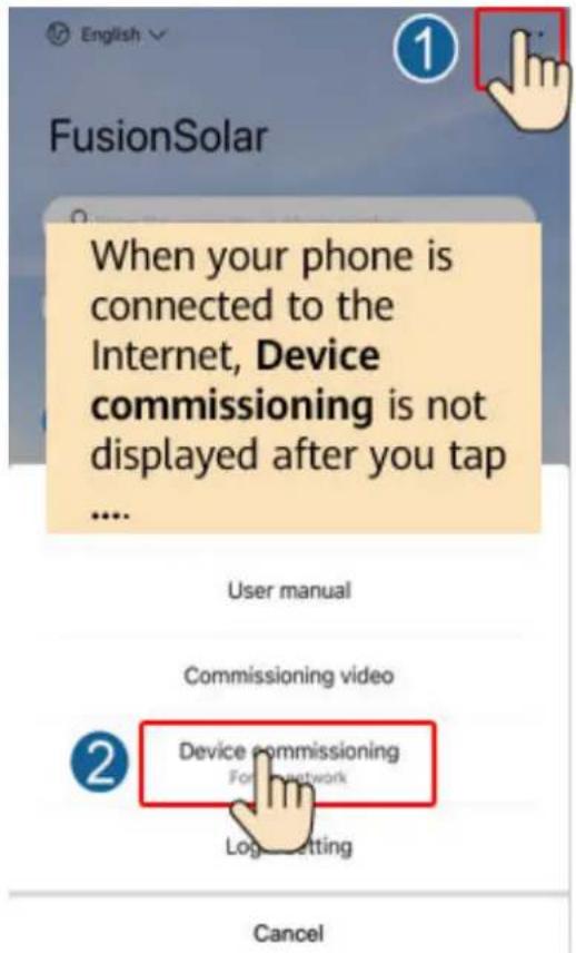
Figure B-2 Method 2: after login (connected to the Internet)
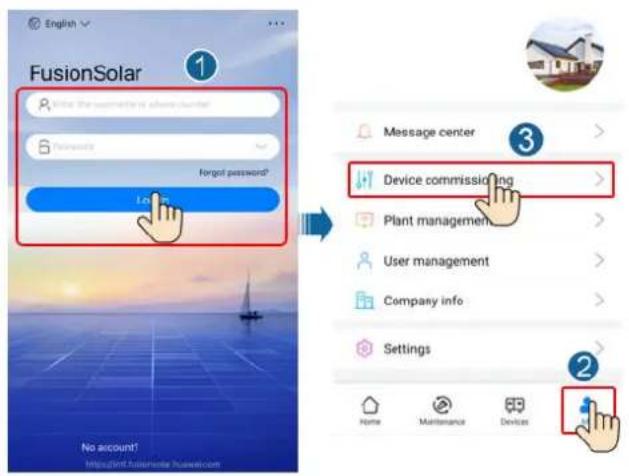
Step 2 Connect to the solar inverter WLAN and log in to the device commissioning screen as the installer user.
NO TICE
- When connecting to the SUN2000 directly from the mobile phone, keep the mobile phone visible within 3 meters of the SUN2000 to ensure the communication quality between the app and SUN2000. The distances are for reference only and may vary with mobile phones and shielding conditions.
- When connecting the SUN2000 to the WLAN over a router, ensure that the mobile phone and SUN2000 are in the WLAN coverage of the router and the SUN2000 is connected to the router.
- The router supports WLAN (IEEE 802.11 b/g/n, 2.4 GHz) and the WLAN signal reaches the SUN2000.
- The WPA, WPA2, or WPA/WPA2 encryption mode is recommended for routers. Enterprise-level encryption is not supported (for example, public hotspots requiring authentication such as airport WLAN). WEP and WPA TKIP are not recommended because these two encryption modes have serious security defects. If the access fails in WEP mode, log in to the router and change the encryption mode of the router to WPA2 or WPA/WPA2.
Figure B-3 Quick settings
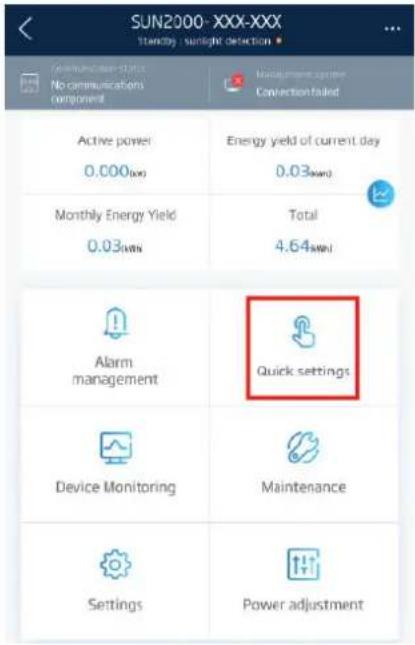

NO TE
- Obtain the initial password for connecting to the solar inverter WLAN from the label on the side of the solar inverter.
- Use the initial password upon first power-on and change it immediately after login. To ensure account security, change the password periodically and keep the new password in mind. Not changing the initial password may cause password disclosure. A password left unchanged for a long period of time may be stolen or cracked. If a password is lost, devices cannot be accessed. In these cases, the user is liable for any loss caused to the PV plant.
- When you access the Device Commissioning screen of the SUN2000 for the first time, you need to manually set the login password because the SUN2000 does not have an initial login password.
----End
C Setting Power Adjustment Parameters
Prerequisites
You have logged in to the app as installer.
Procedure
Step 1 On the home screen, tap Power Adjustment and set power parameters as required.
Figure C-1 Setting Power Adjustment Parameters
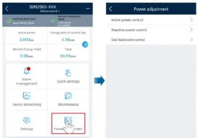
NO TE
Power Quality Response Modes supported by the inverter can be implemented by setting Voltage rise suppression parameters.
Power derating for voltage variation (Volt-Watt mode): The inverter power output will vary in response to the AC grid voltage. This is switched on by default. This mode can be enabled via the configuration App. Please refer to the Set Q-U and P-U through FusionSolar APP, or contact Technical Support for more information.
Reactive power regulation for voltage variation (Volt-VAr mode): The power output or input will vary in response to the AC grid voltage. This function is switched off by default. This mode can be enabled via the configuration App. Please refer to the Set Q-U and P-U through FusionSolar APP, or contact Technical Support for more information.
----End
D
Resetting Password
Step 1 Ensure that the SUN2000 connects to the AC and DC power supplies at the same time. Indicators and are steady green or blink at long intervals for more than 3 minutes.
Step 2 Perform the following operations within 3 minutes:
- Turn off the AC switch and set the DC switch at the bottom of the SUN2000 to OFF. If the SUN2000 connects to batteries, turn off the battery switch. Wait until all the LED indicators on the SUN2000 panel turn off.
- Turn on the AC switch and set the DC switch to ON. Ensure that the indicator is blinking green at long intervals.
- Turn off the AC switch and set the DC switch to OFF. Wait until all LED indicators on the SUN2000 panel are off.
- Turn on the AC switch and set the DC switch to ON. Wait until all indicators on the solar inverter panel blink and turn off 30 seconds later.
Step 3 Reset the password within 10 minutes. (If no operation is performed within 10 minutes, all inverter parameters remain unchanged.)
- Wait until the indicator \~ blinks green at long intervals.
- Obtain the initial WLAN hotspot name (SSID) and initial password (PSW) from the label on the side of the SUN2000 and connect to the app.
- On the login screen, set a new login password and log in to the app.
Figure D-1 Setting the password
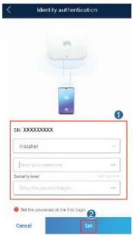
Step 4 Set router and management system parameters to implement remote management.
- Setting router parameters
Log in to the FusionSolar app, choose Device Commissioning > Settings > Communication configuration > Router connection settings, and set router parameters.
Figure D-2 Setting router parameters
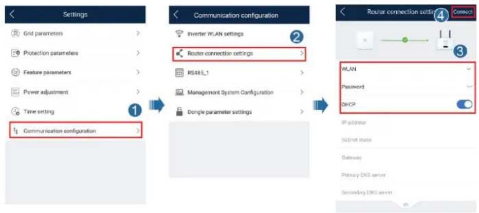
- Setting management system parameters
Log in to the FusionSolar app, choose Device Commissioning > Settings > Communication configuration > Management System Configuration, and set management system parameters.
Figure D-3 Setting management system parameters
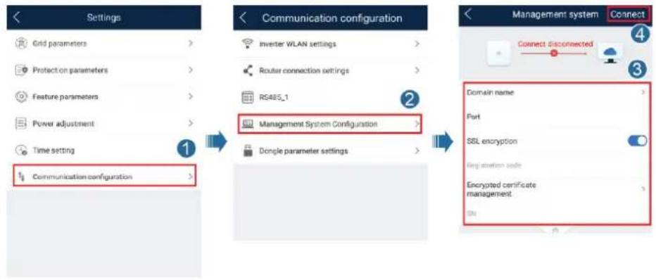
flowchart
graph LR
    A["Settings"] --> B["Communication configuration"]
    B --> C["Management System Configuration"]
    C --> D["Connect"]
    D --> E["Network Management System"]
    style A fill:#f9f,stroke:#333
    style B fill:#ccf,stroke:#333
    style C fill:#cfc,stroke:#333
    style D fill:#fcc,stroke:#333
• (Optional) Resetting the WLAN password
Log in to the FusionSolar app, choose Device Commissioning > Settings > Communication configuration > Inverter WLAN settings, and reset the WLAN password.
Figure D-4 Resetting the WLAN password
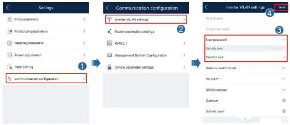
----End
E Rapid Shutdown
NO TE
- If optimizers are configured for some PV modules, the rapid shutdown function is not supported.
- You are advised to periodically check whether the rapid shutdown function is normal.
When all PV modules connected to the solar inverter are configured with optimizers, the PV system shuts down quickly and reduces the output voltage of the PV string to below 30 V within 30 seconds.
Perform the following step to trigger rapid shutdown:
- Method 1: To enable the rapid shutdown function, you need to connect the access switch to pins 13 and 15 of the SUN2000 communications terminal. The switch is closed by default. The rapid shutdown is triggered when the switch changes from closed to open.
- Method 2: Turn off the AC switch between the solar inverter and the power grid.
- Method 3: Set the DC switch at the bottom of the SUN2000 to OFF. (Turning off an extra switch on the DC side of the SUN2000 will not trigger rapid shutdown. The PV string may be energized.)
F Locating Insulation Resistance Faults
If the ground resistance of a PV string connected to a solar inverter is too low, the solar inverter generates a Low Insulation Resistance alarm.
The possible causes are as follows:
- A short circuit occurs between the PV array and the ground.
- The ambient air of the PV array is damp and the insulation between the PV array and the ground is poor.
To locate the fault, connect each PV string to a solar inverter, power on and check the solar inverter, and locate the fault based on the alarm information reported by the FusionSolar app. If a system is not configured with any optimizer, skip the corresponding operations. Perform the following steps to locate an insulation resistance fault.
NO TICE
If two or more ground insulation faults occur in a single PV string, the following method cannot locate the fault. You need to check the PV modules one by one.
Step 1 The AC power supply is connected, and set the DC switch at the bottom of the solar inverter to OFF. If the solar inverter connects to batteries, wait for 1 minute, and turn off the battery switch and then the auxiliary power switch of the battery.
Step 2 Connect each PV string to the solar inverter and set the DC switch to ON. If the solar inverter status is Shutdown: Command, choose Device Commissioning > Maintenance > Inverter ON/OFF on the app and send a startup command.
Step 3 Log in to the FusionSolar app and choose My > Device Commissioning. On the Device Commissioning screen, connect and log in to the solar inverter, and access the Alarm management screen. Check whether the Low Insulation Resistance alarm is reported.
- If the Low Insulation Resistance alarm is not reported one minute after the DC is supplied, choose Device Commissioning > Maintenance > Inverter ON/OFF on the app and send a shutdown command. Set the DC switch to OFF and go to Step 2 to connect another PV string to the solar inverter for a check.
- If a Low Insulation Resistance alarm is still reported one minute after the DC is supplied, check the percentage for possible short-circuit positions on the Alarm details page and go to Step 4.
Figure F-1 Alarm details
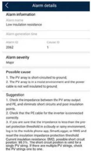
NO TE
- The positive and negative terminals of a PV string are connected to the PV+ and PV-terminals of the solar inverter. The PV- terminal represents a possibility of 0% for the short-circuit position and the PV+ terminal represents a possibility of 100% for the short-circuit position. Other percentages indicate that the fault occurs on a PV module or cable in the PV string.
- Possible fault position = Total number of PV modules in a PV string x Percentage of possible short-circuit positions. For example, if a PV string consists of 14 PV modules and the percentage of the possible short-circuit position is 34%, the possible fault position is 4.76 (14 x 34%), indicating that the fault is located near PV module 4, including the previous and the next PV modules and the cables of PV module 4. The solar inverter has a detection precision of ±1 PV module.
Figure F-2 Definition of the percentage of the short-circuit position
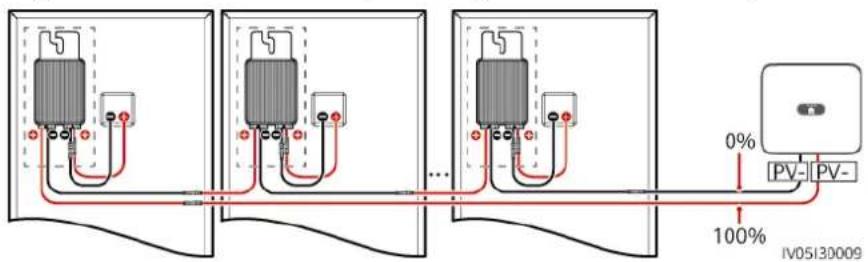
Step 4 Set the DC switch to OFF and check whether the connector or DC cable between the possible faulty PV modules and the corresponding optimizers, or those between the adjacent PV modules and the corresponding optimizers are damaged.
- If yes, replace the damaged connector or DC cable, set the DC switch to ON, and view the alarm information.
- If the Low Insulation Resistance alarm is not reported one minute after the DC is supplied, the inspection on the PV string is complete. Choose
Device Commissioning > Maintenance > Inverter ON/OFF on the app and send a shutdown command. Set the DC switch to OFF. Go to Step 2 to check other PV strings. Then go to Step 8.
- If the Low Insulation Resistance alarm is still reported one minute after the DC is supplied, go to Step 5.
- If not, go to Step 5.
Step 5 Set the DC switch to OFF, disconnect the possible faulty PV modules and corresponding optimizers from the PV string, and connect a DC extension cable with an MC4 connector to the adjacent PV modules or optimizers. Set the DC switch to ON and view the alarm information.
- If the Low Insulation Resistance alarm is not reported one minute after the DC is supplied, the fault occurs on the disconnected PV module and optimizer. Choose Device Commissioning > Maintenance > Inverter ON/OFF on the app and send a shutdown command. Go to Step 7.
- If the Low Insulation Resistance alarm is still reported one minute after the DC is supplied, the fault does not occur on the disconnected PV module or optimizer. Go to Step 6.
Step 6 Set the DC switch to OFF, reconnect the removed PV module and optimizer, and repeat Step 5 to check the adjacent PV modules and optimizers.
Step 7 Determine the position of the ground insulation fault.
-
Disconnect the possible faulty PV module from the optimizer.
-
Set the DC switch to OFF.
-
Connect the possible faulty optimizer to the PV string.
-
Set the DC switch to ON. If the solar inverter status is Shutdown: Command, choose Device Commissioning > Maintenance > Inverter ON/OFF on the app and send a startup command. Check whether the Low Insulation Resistance alarm is reported.
- If the Low Insulation Resistance alarm is not reported one minute after the solar inverter is powered on, the PV module is faulty. Choose Device Commissioning > Maintenance > Inverter ON/OFF on the app and send a shutdown command.
- If the Low Insulation Resistance alarm is still reported one minute after the solar inverter is powered on, the optimizer is faulty.
- Set the DC switch to OFF. Replace the faulty component to rectify the insulation resistance fault. Go to Step 2 to check other PV strings. Then go to Step 8.
Step 8 If the solar inverter connects to batteries, turn on the auxiliary power switch of the battery and then the battery switch. Set the DC switch to ON. If the solar inverter status is Shutdown: Command, choose Device Commissioning > Maintenance > Inverter ON/OFF on the app and send a startup command.
----End

DRM Configuration Guide for Standard
As NZS4777.2
If Demand Response Modes (DRM0) are required, then the installer will need to connect the Huawei SmartLogger3000. Refer to the Huawei document SmartLogger3000 DRM Configuration Guide for Standard AS NZS4777.2 of how to connect the DRED and how to configure the inverter and Smart Logger for use with the DRED.

Acronyms and Abbreviations
L
LED light emitting diode
M
MPP maximum power point
MPPT maximum power point tracking
P
PV photovoltaic