RT310SR - Thermostat Salus - Free user manual and instructions
Find the device manual for free RT310SR Salus in PDF.


User questions about RT310SR Salus
0 question about this device. Answer the ones you know or ask your own.
Ask a new question about this device
Download the instructions for your Thermostat in PDF format for free! Find your manual RT310SR - Salus and take your electronic device back in hand. On this page are published all the documents necessary for the use of your device. RT310SR by Salus.
USER MANUAL RT310SR Salus
natural_image
Digital temperature controller displaying 21.3°C against a blue abstract background (no text or symbols on the device itself)RT310SR THERMOSTAT - FULL USER MANUAL
TABLE OF CONTENTS
1. Introduction......4
1.1 Product Compliance ....4
1.2 Safety Informations....4
2. Product Overview ....5
2.1 Package content....6
2.2 Proper thermostat location ....6
2.3 Wall mounting ....7
3. SR868 smart relay receiver ....8
3.1 Smart relay LED indication ....8
3.2 Connection description....9
4. Before you start (first power up) 10
4.1 LCD icon description ....10
4.2 Button description....10
4.3 First power up sequence and configuration....11
5. User settings ......12
5.1 Manual mode - changing temperature setpoint....12
5.2 Frost protection mode ....13
5.3 Sleep mode ....13
5.4 Heat/Cool mode * 14
6. Installer mode ....15
6.1 DIP switches parameters ....15
7. RT310TX thermostat pairing with the SR868 relay receiver....16
8. RT310TX thermostat pairing with few other receivers ....17
9. Test the pairing process....19
10. Reset function ......20
11. Cleaning and Maintenance ....21
12. Technical Informations ...... 21
13. Warranty 22

natural_image
Abstract curved line design in grayscale, no text or symbols present1. Introduction
1.1 Product Compliance
This product complies with the essential requirements and other relevant provisions of Directives 2014/53/EU and 2011/65/EU. The full text of the EU Declaration of Conformity is available at the following internet address: www.saluslegal.com.
1.2 Safety Informations
- Before starting installation work and before using the product, read the entire manual.
- The information contained in the instructions is essential for proper functioning.
• To avoid accidents resulting in personal injury and material damage, please follow all safety precautions, specified in this manual. - The device should not be used by people with limited mental, sensory or mental abilities, without experience, of insufficient knowledge as well as children.
- Do not use an unassembled device (eg without a cover).
- The device may only be opened by a qualified person.
- Keep electrical devices out of the reach of children and ensure that they do not play with it. Children should not be left unattended. If necessary, disconnect the control system for the entire room.
- Do not leave the packaging, cabinet, or any loose parts of the device unattended, as they pose a risk to children.
WARNING!
• Installation must be carried out by a qualified person with appropriate electrical qualifications in accordance with standards and regulations in force in the given country and in the EU.
- Never try to connect the device other than as described in the manual.
- Before assembly, repair or maintenance as well as during any connection works it is absolutely necessary disconnect the mains supply and make sure that the terminals and electric wires are not live.
- The device may not be exposed to extreme temperatures, strong vibrations or subjected to mechanical shock.
- The device should not be used in unfavorable environmental conditions or in rooms where there is a concentration of flammable gases, fumes or dust.
WARNING!
- There may be additional protection requirements for the entire installation that the installer is responsible for maintaining.
natural_image
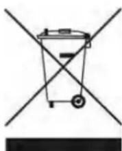
Symbol of a trash bin crossed out by two crossed lines, no text or labels presentCare for the natural environment is of paramount importance to us. The awareness that we manufacture electronic devices obliges us to dispose of used electronic components and devices safely. Therefore the company has received a registration number issued by the Chief Inspector for Environmental Protection. The crossed out symbol the trash can on the product means that the product must not be disposed of with ordinary waste containers. Sorting waste for recycling helps to protect the environment. It is the user's responsibility to surrender used equipment to a designated collection point for recycling waste from electrical and electronic equipment.
2. Product Overview
The RT310 room thermostat simply switches the heating system on and off as necessary. It works by sensing the air temperature, switching on the heating when the air temperature falls below the thermostat setting, and switching it off once this set temperature has been reached. Recommended for controlling e.g. heating panels or electric heaters.
Turning a room thermostat to a higher setting will not make the room heat up any faster. How quickly the room heats up depends on the design of the heating system, for example, the size of boiler and radiators. Neither does the setting affect how quickly the room cools down. Turning a room thermostat to a lower setting will result in the room being controlled at a lower temperature, and saves energy.
The heating system will not work if a time switch or programmer has switched it off.
The way to set and use your room thermostat is to find the lowest temperature setting that you are comfortable with, and then leave it alone to do its job. The best way to do this is to set the room thermostat to a low temperature – say 18^ C – and then turn it up by one degree each day until you are comfortable with the temperature.
You won't have to adjust the thermostat further. Any adjustment above this setting will waste energy and cost you more money.
If your heating system is a boiler with radiators, there will usually be only one room thermostat to control the whole house. But you can have different temperatures in individual rooms by installing thermostatic radiator valves (TRVs) on individual radiators. If you don't have TRVs, you should choose a temperature that is reasonable for the whole house. If you do have TRVs, you can choose a slightly higher setting to make sure that even the coldest room is comfortable, then prevent any overheating in other rooms by adjusting the TRVs.
Room thermostats need a free flow of air to sense the temperature, so they must not be covered by curtains or blocked by furniture. Nearby electric fires, televisions, wall or table lamps may prevent the thermostat from working properly.
Product advantages:
- set factory-paired and ready to work
• has a TPI control algorithm
• automatically repeats the signal - has a frost protection mode (temperature range 5 - 17 degrees)
• correction of the displayed temperature ± 3°C - has a HOLIDAY mode and SLEEP mode (suspending the function, e.g. outside the heating season)
• has unique transmission codes - operates at 868 MHz - a stable and noise-resistant signal
2.1 Package content
1) RT310TX thermostat
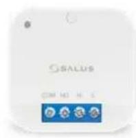
2) SR868 smart relay receiver
2) 2x AA batteries
3) Short instruction
4) Mounting screws
1

text_image
21.32
text_image
SALUS ON MO N L3
4
text_image
SALUS CONTROLS RT310SR 20 Immunisation Guide5

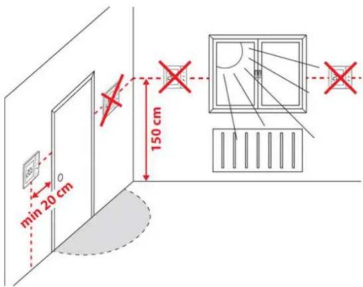
2.2 Proper thermostat location
text_image
min 20 cm 150 cm
Please note:
The ideal position to thermostat mounting is about 1,5m under floor level far from heating or cooling sources. Thermostat can't be exposed to sunlight or any extreme conditions like for example draft.
Because of fire and explosion risk there is not allowed to use thermostat in atmosphere of explosive gases and flammable liquids (eg coal dust). In case if any of listed dangers occur you have to use additional protection measures — anti-dust and explosive gases (tight cover) or prevent their formation. Furthermore, thermostat can't be used in condensation of water vapor conditions and be exposed to water action.
2.3 Wall mounting
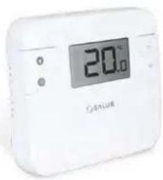
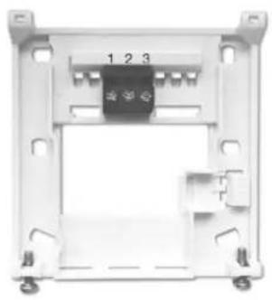
Content used for thermostat mounting:
natural_image
White digital temperature control device with display showing 20°C and 'COSAUS' branding (no readable text beyond branding)RT310 front Backplate
natural_image
Exterior view of a mechanical or electronic component housing with mounting holes and a central black component (no visible text or symbols)(two screws at the bottom)
flowchart
graph TD
    A["1"] --> B["2"]
    B --> C["3"]
    D["COM"] --> A
    E["NC"] --> B
    F["NO"] --> C
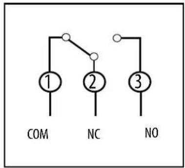
Wiring configuration
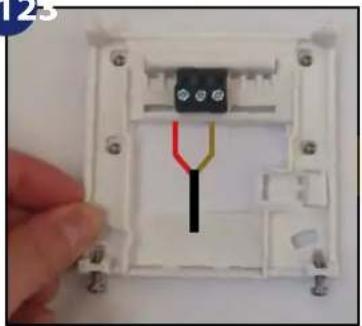
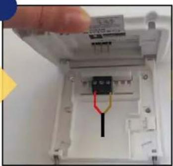
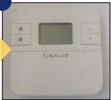
How to mount the thermostat to the wall:
12
natural_image
Close-up of a white plastic electrical connector with black and red wires, held by a hand (no text or symbols visible)Fix the backplate to the wall.
natural_image
Close-up of a hand inserting a black connector into a white electronic device (no visible text or symbols)Align the front housing at the top edge.
natural_image
White electronic device labeled 'SEALUS' with control buttons and a central display (no readable text beyond branding)Fit the front housing. Press lightly.
3. SR868 smart relay receiver
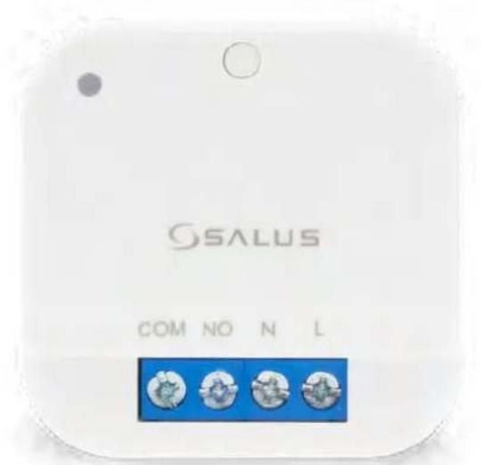
The SALUS SR868 relay gives you control of the electrical heating. SR868 must be used in conjunction with the wireless RT series thermostats. The thermostat communicates wirelessly with the SR868 smart plug receiver. The receiver should be supplied with 230VAC, the maximum load of the receiver is 16A. Avoid installing the device in places directly exposed to water, moisture and air condensation.
text_image
SALUS COM NÓ N L3.1 Smart relay LED indication
Smart relay receiver has designed LED diode in the left upper corner. Here is description what an every single colour and diode means:
| LED State Description | ||
| Red | On The relay is off. | |
| Flash The relay is in pairing mode. | ||
| Green | On The relay is on. | |
| 2 x Flash The relay is writing pairing code. | ||
| Red and Green | Flash alternately The relay is paired but lost link. | |
| Flash in different sequence It indicates the software version after reboot. | ||
3.2 Connection description
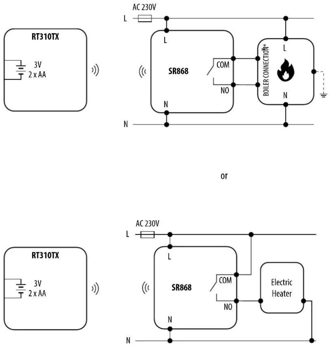
Legend: Symbols explanation:

Boiler - Boiler connection*
- Boiler's contacts for ON/OFF thermostat (according to the boiler's instructions)
L, N - power supply 230V
COM, NO - voltage-free output
- Before you start (first power up)
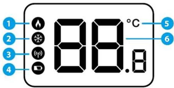
4.1 LCD icon description
text_image
1 2 3 4 88.8°C 5 6- Heating Mode indication
- Cooling Mode */Frost protection mode indication
-
RF signal indicator (only in RT310RF)
-
Low battery status
- Temperature unit
- Room / setpoint temperature
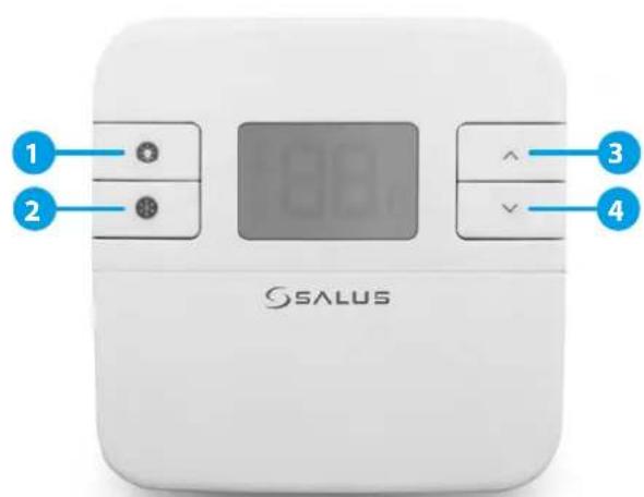
4.2 Button description
text_image
1 2 3 4 SALUS- Turn on the LCD backlight
-
HEAT/COOL * modes change or Frost Protection mode activation (only when HEAT mode is enabled)
-
Increase button
- Decrease button

PLEASE NOTE! The LCD screen can be activated by using any button.
* Function available only from firmware version 2.1
4.3 First power up sequence and configuration
To power up the thermostat you have to put the batteries inside. Then thermostat will display following sequence:

text_image
1Remove the protection foil and insert 2xAA batteries by removing front cover.

text_image
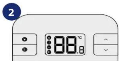
2 88.0℃After that, thermostat will automatically power up and it will display all icons...
text_image
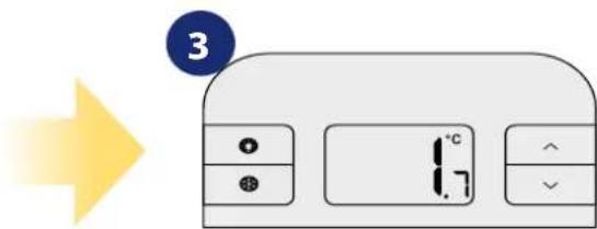
3...then thermostat will display the software version.

text_image
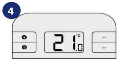
4 21.0When thermostat is successfully powered up, main screen will be displayed.
5. User settings
5.1 Manual mode - changing temperature setpoint
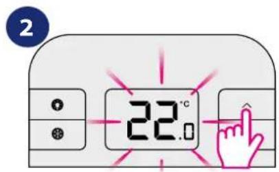
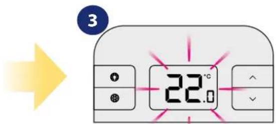
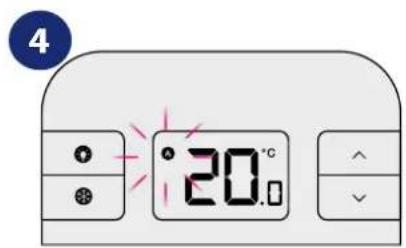
In manual mode, the thermostat maintains a constant temperature set by the user. To set temperature setpoint follow steps below:
text_image
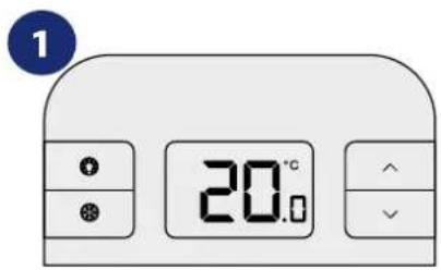
1 20.0First, thermostat is displaying actual room temperature.

text_image
2 22.0Press or to set the new temperature setpoint.
text_image
3 22.0Now wait 2 seconds timeout to approve the changes.

text_image
4 ° 20.0Thermostat will display main screen (actual room temperature).
5.2 Frost protection mode
In this mode the setpoint temperature is automatically set to frost setpoint to prevent pipes from freezing. If the room temperature is lower than the frost setpoint, frost protection will be enabled. To set frost protection mode follow steps below:
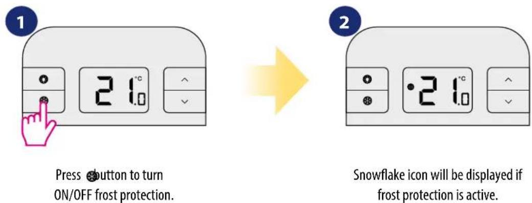
Press 📍 button to turn ON/OFF frost protection.
Snowflake icon will be displayed if frost protection is active.

The Frostpoint temperature can be reviewed by pressing the UP button once, but can only be changed in Installer Mode. Frost protection mode can be enabled only in HEAT mode.
5.3 Sleep mode
In sleep mode thermostat is switched off and doesn't consume any energy and it is impossible to make an action until you activate the thermostat again. To activate/deactivate sleep mode follow steps below:
TO ACTIVATE SLEEP MODE:
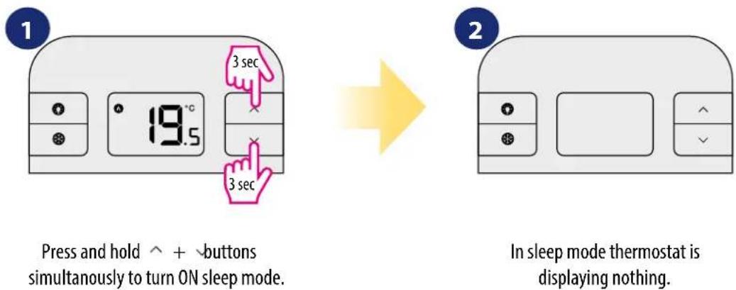
Press and hold ^ + √buttons simultaneously to turn ON sleep mode.
In sleep mode thermostat is displaying nothing.
TO DEACTIVATE SLEEP MODE:
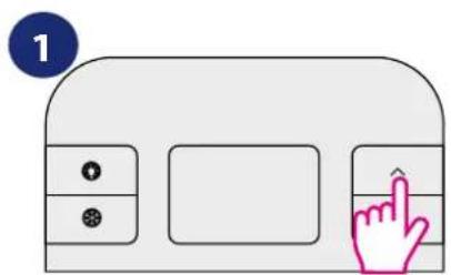
text_image
1To deactivate sleep mode press any button.


text_image
2 19.5Thermostat will go back to work and display main screen.
5.4 Heat/Cool mode \*
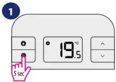
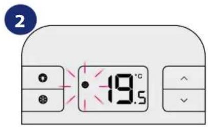
User can set thermostat for heating or cooling. In HEAT mode thermostat is displaying flame icon all the time. When thermostat is in HEAT mode and thermostat is CALLING for HEAT – the flame icon is flashing. In COOL mode thermostat is displaying snowflake icon all the time. When thermostat is switched to the COOLING mode and the thermostat is CALLING for COOL – then the snowflake icon is flashing. Default mode is HEAT MODE.
NOTE: every time when thermostat need to start call for cooling then it can be delayed for about 3 minutes.
To set selected mode please follow steps below:
HOW TO SET COOLING MODE:
text_image
1 19.5 5 secBy default thermostat is in HEATING mode (flame icon is displaying). To change the thermostat into the COOLING mode – press and hold the SNOWFLAKE button for 5 seconds.

text_image
2 19.5When thermostat is switched to the COOLING mode – the snowflake icon is steady ON. If thermostat is CALLING for COOL – then the snowflake icon is flashing.
HOW TO SET HEATING MODE:
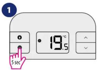
text_image
1 19.5 5 secTo change the thermostat into the HEATING mode – press and hold the SNOWFLAKE button for 5 seconds.

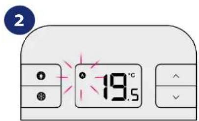
text_image
2 19.5When thermostat is switched to the HEATING mode – the flame icon is steady ON. If thermostat is CALLING for HEAT – then the flame icon is flashing.
* Function available only from firmware version 2.1
6. Installer mode
To enter installer parameters please follow steps below. Please refer to parameters table description before any changes. Use ⚙ button to move through parameters. Use ^or for adjustments. Every change/selection confirm by button.
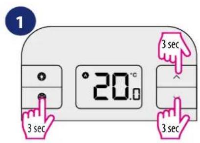
text_image
1 20.0 3 sec 3 sec 3 secPress and hold ⚙ + ^+ ∨ simultaneously for about 3 seconds to enter the installer mode.

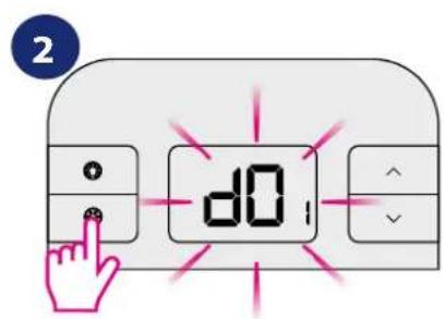
text_image
2 d0Use ⚙button to move through parameters. Use or for adjustments. Every change/selection confirm by ⚙button.
DETAILED TABLE WITH ALL INSTALLER PARAMETERS:
| dxx Function Parameter | Default value | |
| d01 Temperature display accuracy 0.1°C or 0.5°C 0.5°C | ||
| d02 Temperature offset +/- 3.0°C 0.0°C | ||
| d03 Frost Protection setpoint temperature 5.0°C - 17.0°C 5.0°C |
6.1 DIP switches parameters
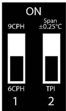
DIP switches are used to set chosen control algorithm. They are located under back cover of the thermostat (please refer to the picture below):
The position of the DIP switches determines the type of control algorithm:
| 1 | 2 | Cooling * | Heating | Default value |
| ON | ON | Hysteresis +/- 0.25 | Hysteresis +/- 0.25 | |
| OFF | ON Hysteresis +/- 1.5 | Hysteresis +/- 0.5 | ||
| ON | OFF | Hysteresis +/- 1.0 | TPI 9 CPH | |
| OFF | OFF | Hysteresis +/- 0.5 | TPI 6 CPH | √ |
text_image
ON 9CPH Span ±0.25°C 6CPH 1 TPI 2
PLEASE NOTE! TPI algorithm is recommended for underfloor heating. It can be adjusted between a low comfort level (6 CPH) and a higher comfort level (9 CPH). "CPH" means cycles per hour and it relates to the frequency of the measurement cycles performed by thermostat.
* Function available only from firmware version 2.1
7. RT310TX thermostat pairing with the SR868 relay receiver
The word PAIRING in the user settings means the function of synchronizing the transmitter with the receiver again, if it has been removed.

WARNING!
IN THE SET RT310SR THE THERMOSTAT IS FACTORY PAIRED WITH THE SR868 RECEIVER!
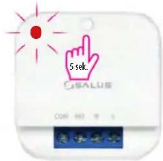
In order to pair the devices correctly, you must first prepare the receiver for synchronization!

text_image
5 sek. Gsalus COM NO. 1Connect the receiver to a 230V power supply (see its manual). Press and hold the button. After 5 seconds, the red LED will flash, which means the SR868 relay is ready to pair with the thermostat.
text_image
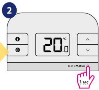
2 20.0 TEST / PAIRING 3 secPress and hold TEST / PAIRING button for 3 seconds.

text_image
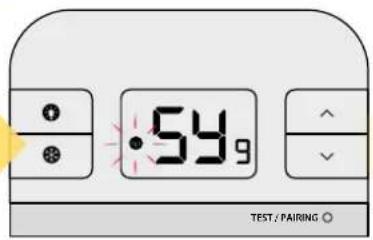
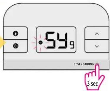
54.9 TEST / PAIRING ©Thermostat started pairing process. It can take up to 9 minutes.
Attention! Forcing the pairing process will generate a new communication code. All receivers previously paired with the thermostat will be irretrievably deleted from its memory.

natural_image
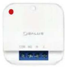
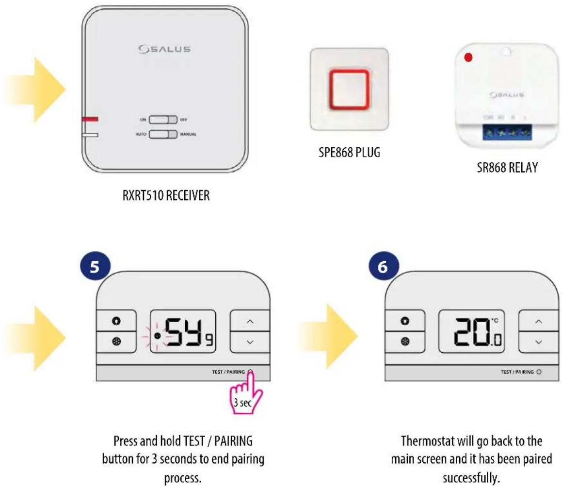
White electronic device labeled 'OSALUS' with a red indicator light and a small display screen below (no readable text or symbols on the device itself)When the red diode on the receiver lights up continuously, the devices have been paired on a new frequency.

text_image
54.9 TEST / PAIRING 3 secPress and hold TEST / PAIRING button for 3 seconds to end pairing process.

text_image
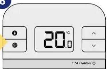
20.0 TEST / PAIRING ©Thermostat will go back to the main screen and it has been paired successfully.
8. RT310TX thermostat pairing with few other receivers
The word PAIRING in the user settings means the function of synchronizing the transmitter with the receiver again, if it has been removed.

REMEMBER! If the thermostat is already paired with any receiver, you will have to pair it again with other receivers. You can pair few receivers with 1 thermostat RTRX510, SPE868 and SR868.

FIRST, PREPARE ALL THE RECEIVERS YOU WANT TO PAIR WITH THE THERMOSTAT. THE PREPARATION OF THE RECEIVERS FOR THE PAIRING PROCESS IS CONFIRMATION OF THE RED LED FLASHING ON THEM.
flowchart
graph LR
    A["GSALUS"] --> B["GSALUS"]
    B --> C["GSALUS"]
RXRT510 RECEIVER RXRT510 RECEIVER RXRT510 RECEIVER
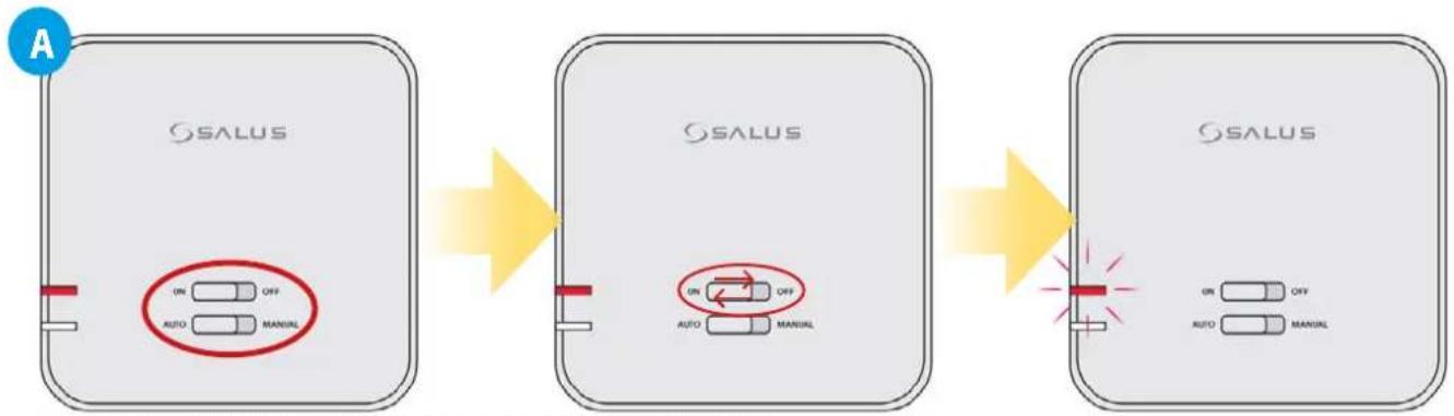
If you want to re-pair the devices with each other, make sure that the receiver is disconnected from the power supply and the switches on it are in the AUTO and ON positions. Then connect the receiver to the power supply and wait for the red diode to glow continuously.
Move the top switch to the OFF position with a quick motion and back to the ON position.
The red LED will start blinking, which will confirm that the receiver has entered the pairing mode.
text_image
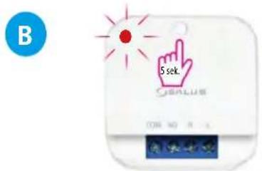
B 5 sek. SARUSSR868 RELAY
Connect the receiver to a 230V power supply (see its manual). Press and hold the button. After 5 seconds, the red LED will flash, which means the SR868 relay is ready to pair with the thermostat.
text_image
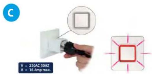
C V = 230AC 50HZ A = 16 Amp max.SPE868 PLUG
Connect the plug to a 230V power supply (see its manual). Press and hold the button. After 5 seconds, the red LED will flash, which means the SPE868 plug is ready to pair with the thermostat.
text_image
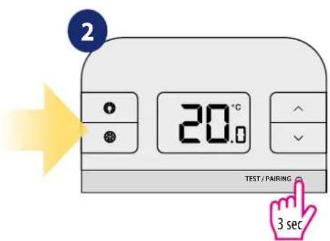
2 20.0°C TEST / PAIRING 3 secPress and hold TEST / PAIRING button for 3 seconds.
text_image
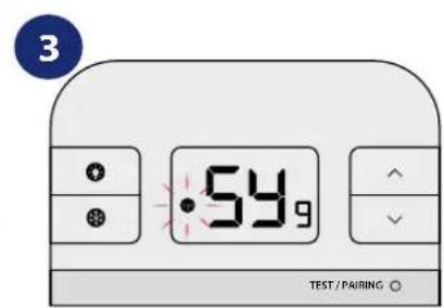
3 54,9 TEST / PAIRING ○Thermostat started pairing process. It can take up to 9 minutes. Attention! Forcing the pairing process will generate a new communication code. All receivers previously paired with the thermostat will be irretrievably deleted from its memory.

AFTER A SUCCESSFUL PAIRING, THE RECEIVER'S LEDS WILL GLOW CONSTANTLY RED:
9. Test the pairing process
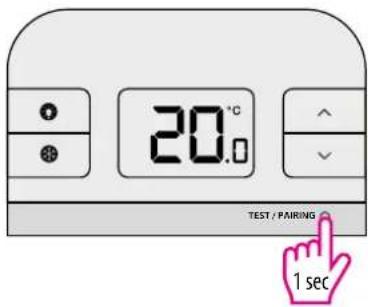
It is important to place the receiver and transmitter in places where nothing interferes with the radio signal. The range of communication between the transmitter and the receiver in an open area is up to 60m. The radio transmission is influenced by many factors that can shorten the working distance, such as thick walls, drywall covered with aluminum foil, metal objects such as cabinets, general radio interference, etc. However, the range is sufficient for most domestic use. It is recommended to test the radio transmission between devices before mounting the regulator on the wall. The test can be performed by changing the set temperature, i.e. by activating or deactivating the heating.
12
text_image
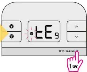
20.0°C TEST / PAIRING 1 secPress TEST / PAIRING button to check the connection with the receiver.
●
text_image
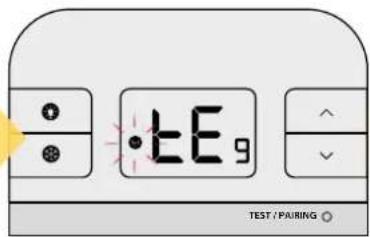
tE9 TEST / PAIRING ©Antenna icon will display. Test mode can take up to 9 minutes.
[Non-Text]
natural_image
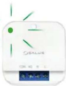
White electronic device with green LED and 'OSALUS' branding (no readable text or symbols beyond branding)The green LED on the SR868 smart plug receiver will begin to flash.
4
text_image
±E9 TEST / PAIRING 1 secPress TEST / PAIRING button again to return to the main screen.
5
natural_image
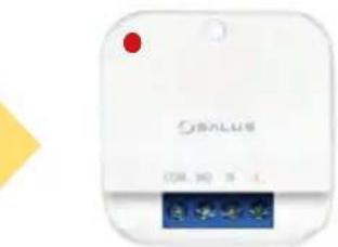
White OSVALUS device with a red indicator light and a blue display screen (no readable text or symbols)SR868 will go back to normal work mode.

If you purchased an SR868 or RT310TX and intend pairing with other devices in the 5x5 range, please refer to the Receiver Units manual or the relevant manuals available at www.salus-controls.eu
10. Reset function
To RESET RT310 thermostat please follow steps below:
text_image
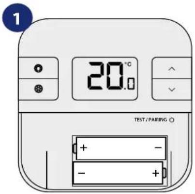
1 20.0 TEST / PAIRING ○ + - - - +Remove the batteries without pressing any button. Wait 2 minutes and insert the batteries again. Your device will be restarted.

When you want to change the batteries your device will use the internal memory to backup your settings. You have 30 seconds to change the batteries before losing your settings.
11. Cleaning and Maintenance
The RT310SR requires no special maintenance. Periodically, the outer casing can be wiped clean using a dry cloth (please DO NOT use solvents, polishes, detergents or abrasive cleaners, as these can damage the thermostat). There are no user serviceable parts within the unit; any servicing or repairs could only be carried out by Salus Controls or their appointed agents.
12. Technical Informations
| Transmitter's power supply 2 x AA batteries | |
| Receiver's power supply 230V AC 50 Hz | |
| Rating max 16 (5) A | |
| Output signal NO/COM relay | |
| Temperature range 5 - 35°C | |
| Display temperature accuracy 0.1°C or 0 | 5°C |
| Control algorithm TPI or Hysteresis: ±0.25°C | |
| Communication Wireless, 868Mhz | |
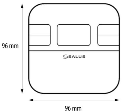
| Dimension [mm] | transmitter: 96 x 96 x 27receiver: 44 x 44 x 26 |
text_image
96 mm GSALUS 96 mm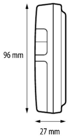
text_image
96 mm 27 mm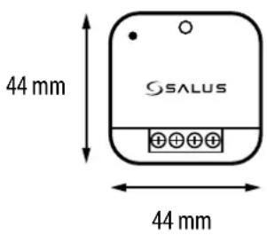
text_image
44 mm SALUS 44 mm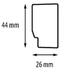
text_image
44 mm 26 mm13. Warranty
SALUS Controls warrants that this product will be free from any defect in materials or workmanship, and shall perform in accordance with its specification, for a period of five years from the date of installation. SALUS Controls sole liability for breach of this warranty will be (at its option) to repair or replace the defective product.
| Customer Name:...... |
| Customer Address:......Post Code:...... |
| Tel No:......Email:...... |
| Company Name:...... |
| Tel No:......Email:...... |
| Installation Date:...... |
| Installer Name:...... |
| Installer Signature:...... |

natural_image
Abstract curved line design in grayscale, no text or symbols presentIMPORTER:
QL CONTROLS Sp. z o.o. Sp. k.
6/F, Building 20E, Phase 3, Hong Kong Science
Park, 20 Science Park East Avenue, Shatin,
New Territories, Hong Kong

Computime

text_image
nqa. ISO 9001 Registered UKAS QUALITY MANAGEMENT 015www.salus-controls.eu
SALUS Controls is a member of the Computime Group.
Maintaining a policy of continuous product development SALUS Controls plc reserve the right to change specification, design and materials of products listed in this brochure without prior notice.
Ver. 2
Issued: 27 | 2021
Soft version: 2.1