
SUN2000MA-20KTL-M0 - Solar panel HUAWEI - Free user manual and instructions
Find the device manual for free SUN2000MA-20KTL-M0 HUAWEI in PDF.

| Product Type | Three-phase grid-tied PV string inverter |
| Model Number | SUN2000-20KTL-M0 |
| Dimensions (W x H x D) | 525 mm x 470 mm x 262 mm |
| Weight | 25 kg |
| Maximum Efficiency | 98.65% |
| European Efficiency | 98.3% |
| Maximum Input Voltage | 1080 V DC |
| Operating Voltage Range | 160–950 V DC |
| Full-load MPPT Voltage Range | 480–850 V DC |
| Maximum Input Current per MPPT | 22 A |
| Number of MPP Trackers | 2 |
| Rated Active Power | 20000 W |
| Maximum Apparent Power | 22000 VA |
| Rated Output Voltage | 220/380 V, 230/400 V, 3W+(N)+PE |
| Rated Output Current (at 380 V) | 30.4 A |
| Maximum Output Current | 33.5 A |
| Power Factor | 0.8 leading to 0.8 lagging |
| Grid Frequency | 50/60 Hz |
| Total Harmonic Distortion | < 3% |
| Protection Features | AFCI, anti-islanding, overvoltage, overcurrent, short-circuit, reverse polarity, insulation resistance detection, DC and AC surge protection |
| Communication | RS485, WLAN+App, optional 4G/WLAN Smart Dongle |
| IP Rating | IP65 |
| Cooling Method | Natural convection |
| Operating Temperature Range | -25°C to +60°C (derated above 45°C) |
| Maximum Operating Altitude | 4000 m (derated above 2000 m) |
Frequently Asked Questions - SUN2000MA-20KTL-M0 HUAWEI
User questions about SUN2000MA-20KTL-M0 HUAWEI
0 question about this device. Answer the ones you know or ask your own.
Ask a new question about this device
Download the instructions for your Solar panel in PDF format for free! Find your manual SUN2000MA-20KTL-M0 - HUAWEI and take your electronic device back in hand. On this page are published all the documents necessary for the use of your device. SUN2000MA-20KTL-M0 by HUAWEI.
USER MANUAL SUN2000MA-20KTL-M0 HUAWEI
natural_image
Abstract geometric shape with a white diagonal stripe dividing a gray rectangle (no text or symbols)
natural_image
Abstract composition of blue geometric shapes with varying circle sizes and shades (no text or symbols)SUN2000-(8KTL, 10KTL, 12KTL, 15KTL, 17KTL, 20KTL)-M0
User Manual
Issue 03
Date 2019-07-19
HUAWEI TECHNOLOGIES CO., LTD.
Copyright © Huawei Technologies Co., Ltd. 2019. All rights reserved.
No part of this document may be reproduced or transmitted in any form or by any means without prior written consent of Huawei Technologies Co., Ltd.
Trademarks and Permissions

and other Huawei trademarks are trademarks of Huawei Technologies Co., Ltd.
All other trademarks and trade names mentioned in this document are the property of their respective holders.
Notice
The purchased products, services and features are stipulated by the contract made between Huawei and the customer. All or part of the products, services and features described in this document may not be within the purchase scope or the usage scope. Unless otherwise specified in the contract, all statements, information, and recommendations in this document are provided "AS IS" without warranties, guarantees or representations of any kind, either express or implied.
The information in this document is subject to change without notice. Every effort has been made in the preparation of this document to ensure accuracy of the contents, but all statements, information, and recommendations in this document do not constitute a warranty of any kind, express or implied.
Huawei Technologies Co., Ltd.
Address: Huawei Industrial Base
Bantian, Longgang
Shenzhen 518129
People's Republic of China
Website: http://e.huawei.com
About This Document
Purpose
This document describes the SUN2000-8KTL-M0, SUN2000-10KTL-M0, SUN2000-12KTL-M0, SUN2000-15KTL-M0, SUN2000-17KTL-M0, and SUN2000-20KTL-M0 (SUN2000 for short) in terms of installation, electrical connections, commissioning, maintenance, and troubleshooting. Read this document through, understand the safety information, and get familiar with the functions and features of the SUN2000 before installing and operating it.

NOTE
The SUN2000-8KTL-M0 and SUN2000-10KTL-M0 inverters are applicable only to Australia.
Intended Audience
This document is intended for:
- Installers
- Users
Symbol Conventions
The symbols that may be found in this document are defined as follows.
| Symbol | Description | |
 | Indicates an imminently hazardous situation which, if not avoided, will result in serious injury or death. | |
 | Indicates a potentially hazardous situation which, if not avoided, could result in serious injury or death. | |
 | Indicates a potentially hazardous situation which, if not avoided, may result in minor or moderate injury. | |
| Symbol | Description |
 | Indicates a potentially hazardous situation which, if not avoided, could result in equipment damage, data loss, performance deterioration, or unanticipated results.NOTICE is used to address practices not related to personal injury. |
 | Calls attention to important information, best practices and tips.NOTE is used to address information not related to personal injury, equipment damage, or environment deterioration. |
Change History
Changes between document issues are cumulative. The latest document issue contains all updates made in previous issues.
Issue 03 (2019-07-19)
• Added E Starting AFCI Check.
- Added F IPS Test (for Italy CEI0-21 Grid Code only).
- Added SUN2000-8KTL-M0 and SUN2000-10KTL-M0 inverters are applicable only to Australia.
Issue 02 (2019-06-30)
- Added C Setting Export Limitation Parameters.
- Added D Setting Voltage Rise Suppression Q-U Curve.
Issue 01 (2019-05-08)
This issue is used for first office application (FOA).
Contents
About This Document...... ii
1 Safety Precautions....1
2 Overview....4
2.1 Product Introduction ...... 4
2.2 Appearance 7
2.3 Label Description....9
2.3.1 Enclosure Labels....9
2.3.2 Product Nameplate....10
2.4 Working Principles.... 11
2.4.1 Circuit Diagram 11
2.4.2 Working Modes....11
3 Storage....14
4 Installation....15
4.1 Checking Before Installation .... 15
4.2 Tools 15
4.3 Determining the Installation Position .... 17
4.3.1 Environment Requirements .... 17
4.3.2 Space Requirements....17
4.4 Moving an Inverter 21
4.5 Installing the Mounting Bracket 22
4.5.1 Wall-mounted Installation....23
4.5.2 Support-mounted Installation 25
5 Electrical Connections....29
5.1 Preparing for Installation 30
5.2 Connecting the PE cable 33
5.3 Connecting the AC Output Power Cable 35
5.4 Connecting the DC input power cable 39
5.5 (Optional) Installing the Smart Dongle....44
5.6 (Optional) Installing the Signal Cable 44
5.6.1 Connecting the RS485 Communications Cable (Inverter Cascading) 47
5.6.2 Connecting the RS485 Communications Cable (Smart Power Sensor)....48
5.6.3 Connecting the Power Grid Scheduling Signal Cable 50
6 Commissioning....53
6.1 Check Before Power-On....53
6.2 Powering On the System....54
6.3 Commissioning....55
6.3.1 Scenario 1: Single inverter + Smart Dongle .....55
6.3.2 Scenario 2: Multiple Inverters + SmartLogger1000A ....58
6.3.3 Other Scenarios....58
6.4 Powering Off the System....61
7 Maintenance....62
7.1 Routine Maintenance....62
7.2 Troubleshooting....63
8 Handling the Inverter....70
8.1 Removing the SUN2000....70
8.2 Packing the SUN2000....70
8.3 Disposing of the SUN2000....70
9 Technical Data....71
A Grid Codes....76
B Setting Dry Contact Scheduling Parameters....80
C Setting Export Limitation Parameters 82
D Setting Voltage Rise Suppression Q-U Curve 85
E Starting AFCI Check 87
F IPS Test (for Italy CEI0-21 Grid Code only) 88
G DRM Configuration Guide for Standard AS NZS4777.2....91
H Acronyms and Abbreviations....92
1 Safety Precautions
Safety
NOTICE
- Before performing operations, read through this manual and follow all the precautions to prevent accidents. The DANGER, WARNING, CAUTION, and NOTICE statements in this document do not represent all the safety instructions. They are only supplements to the safety instructions.
- Only certified electricians are allowed to install, connect cables for, commission, maintain, and troubleshoot Huawei products, and they must understand basic safety precautions to avoid hazards.
When operating Huawei equipment, in addition to following the general precautions in this document, follow the specific safety instructions given by Huawei. Huawei will not be liable for any consequence caused by the violation of the safety operation regulations and design, production, and usage standards.
Disclaimer
Huawei shall not be liable for any consequence caused by any of the following events:
• Damage during the transportation by the customer
• Storage conditions that do not meet the requirements specified in this document.
- Incorrect storage, installation, or use
• Installation or use by unqualified personnel
- Failure to follow the operation instructions and safety precautions in this document
• Operation in extreme environments which are not covered in this document
• Operation beyond specified ranges.
• Unauthorized modifications to the product or software code or removal of the product
• Device damage due to force majeure (such as earthquake, fire, and storm)
• Warranty expiration without extension of warranty service.
- Installation or use in environments which are not specified in relevant international standards
Personnel Requirements
• Operation personnel should receive professional training.
• Operation personnel should read through this document and follow all the precautions.
- Operation personnel should be familiar with the safety standards relevant to electrical systems.
- Operation personnel should understand the composition and working principles of the grid-tied PV system and be aware of local regulations.
• Operation personnel must wear proper personal protective equipment (PPE).
Protecting Labels
Do not scrawl, damage, or block any warning label on the device.
Installation
DANGER
Never power on the SUN2000 during installation.
- Ensure that the SUN2000 is not connected to a power supply or powered on before finishing installation.
- Ensure that the SUN2000 is installed in a well-ventilated environment.
- Ensure that the SUN2000 heat sinks are free from blockage.
• Do not open the front panel of the SUN2000. - Do not remove the terminals and ports at the bottom of the SUN2000.
Grounding
- When installing the device, always make the ground connection first and disconnect it in the end.
• Do not damage the ground conductor.
Electrical Connections
DANGER
Before connecting cables, ensure that the SUN2000 is secured in position and not damaged in any way. Otherwise, electric shock or fire may occur.
- Ensure that all electrical connections comply with local electrical standards.
- Obtain approval from the local utility company before using the SUN2000 to generate electricity in grid-tied mode.
- Ensure that the cables used in a grid-tied PV system are properly connected and insulated and meet all specification requirements.
Operation
DANGER
High voltage may cause an electric shock, which results in serious property damage, serious injury, or death from the SUN2000 in operation. Strictly comply with the safety precautions in this document and associated documents when operating the SUN2000.
• Before operating a device, ensure that it is properly grounded.
- Do not touch an energized SUN2000 because the heat sink reaches a high temperature.
- Follow local laws and regulations when operating the equipment.
Commissioning
When the SUN2000 is powered on for the first time, only qualified personnel are allowed to set the parameters on Quick Setting. Incorrect settings may cause the SUN2000 to conflict with the local certification, which affects the normal operation of the SUN2000.
Maintenance and Replacement
DANGER
High voltage may cause an electric shock, which results in serious property damage, serious injury, or death, or serious property damage from the SUN2000 in operation. Prior to maintenance, power off the SUN2000 and strictly comply with the safety precautions in this document and associated documents when operating the SUN2000.
- A faulty SUN2000 requires overall maintenance. Contact your dealer if the SUN2000 is faulty.
- Maintain the SUN2000 with sufficient knowledge of this document, proper tools, and testing equipment.
- Before maintaining the SUN2000, power it off and follow the instructions on the delay discharge label. Wait for a proper time to operate the SUN2000.
- Place temporary warning signs or erect fences to prevent unauthorized access to the maintenance site.
- Rectify any fault that may compromise the SUN2000 security performance before powering it on again.
- Observe ESD precautions during maintenance.
2 Overview
2.1 Product Introduction
Function
The SUN2000 is a three-phase grid-tied PV string inverter that converts the DC power generated by PV strings into AC power and feeds the power into the power grid.
Models
This document involves the following product models:
• SUN2000-8KTL-M0
• SUN2000-10KTL-M0
• SUN2000-12KTL-M0
• SUN2000-15KTL-M0
• SUN2000-17KTL-M0
• SUN2000-20KTL-M0
The SUN2000-8KTL-M0 and SUN2000-10KTL-M0 inverters are applicable only to Australia.
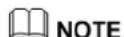
Figure 2-1 Model description (SUN2000-20KTL-M0 is used as an example)
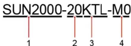
Table 2-1 Model description
| Icon | Meaning | Description |
| 1 | Product | SUN2000: three-phase grid-tied PV string inverter |
| 2 | Power level | 8K: The rated power is 8 kW.10K: The rated power is 10 kW.12K: The rated power is 12 kW.15K: The rated power is 15 kW.17K: The rated power is 17 kW.20K: The rated power is 20 kW. |
| 3 | Topology | TL: transformerless |
| 4 | Product code | M0: the product series with the 1100 V DC input voltage |
Network Application
The SUN2000 applies to grid-tied PV systems for residential rooftops and small ground plants. Typically, a grid-tied system consists of the PV string, SUN2000, AC switch, and alternating current distribution unit (ACDU).
Figure 2-2 Networking application (optional in dashed boxes)
flowchart
graph TD
    A["Solar Panel A"] --> B["B"]
    B --> C["C"]
    C --> D["D"]
    D --> E["E"]
    E --> F["F"]
    F --> G["G"]
    H["Mobile Phone M"] --> E
    I["Water Heater"] --> F
    J["Water Heater"] --> H
    K["Power Transmission Tower"] --> G
    L["Water Transmission Tower"] --> H
    N["Water Transmission Tower"] --> F
    O["Water Transmission Tower"] --> H
    P["Water Transmission Tower"] --> I
    Q["Water Transmission Tower"] --> J
    R["Water Transmission Tower"] --> K
    S["Water Transmission Tower"] --> L
    T["Water Transmission Tower"] --> H
    U["Water Transmission Tower"] --> I
    V["Water Transmission Tower"] --> J
    W["Water Transmission Tower"] --> K
    X["Water Transmission Tower"] --> L
    Y["Water Transmission Tower"] --> H
    Z["Water Transmission Tower"] --> I
    AA["Water Transmission Tower"] --> J
    AB["Water Transmission Tower"] --> K
    AC["Water Transmission Tower"] --> L
    AD["Water Transmission Tower"] --> H
    AE["Water Transmission Tower"] --> I
    AF["Water Transmission Tower"] --> J
    AG["Water Transmission Tower"] --> K
    AH["Water Transmission Tower"] --> L
    AI["Water Transmission Tower"] --> H
    AJ["Water Transmission Tower"] --> I
    AK["Water Transmission Tower"] --> J
    AL["Water Transmission Tower"] --> K
    AM["Water Transmission Tower"] --> L
    AN["Water Transmission Tower"] --> H
    AO["Water Transmission Tower"] --> I
    AP["Water Transmission Tower"] --> J
    AQ["Water Transmission Tower"] --> K
    AR["Water Transmission Tower"] --> L
    AS["Water Transmission Tower"] --> H
    AT["Water Transmission Tower"] --> I
    AU["Water Transmission Tower"] --> J
    AV["Water Transmission Tower"] --> K
    AW["Water Transmission Tower"] --> L
    AX["Water Transmission Tower"] --> H
    AY["Power Supply"] --> BZ["B"]
    AZ["Power Supply"] --> BC["C"]
    BA["Power Supply"] --> BD["D"]
    BB["Power Supply"] --> BC["C"]
    BC["C"] --> BD["D"]
    BD["D"] --> BC["C"]
    BE["Power Supply"] --> BF["E"]
    BG["Power Supply"] --> BH["F"]
    BI["Power Supply"] --> BJ["M"]
    BK["Power Supply"] --> BL["N"]
    BM["Power Supply"] --> BN["L"]
    BO["Power Supply"] --> BP["L"]
    BZ["B"] --> BC["C"]
    BC["C"] --> BD["D"]
    BD["D"] --> BE["Power Supply"]
    BE["Power Supply"] --> BF["C"]
    BF["C"] --> BD["D"]
    BG["M"] --> BH["F"]
    BH["F"] --> BI["N"]
    BJ["N"] --> BK["L"]
    BK["L"] --> BL["L"]
    BN["L"] --> BK["L"]
    BL["L"] --> BK["L"]

NOTE
- indicates a power cable, - indicates a signal cable, - indicates wireless communication.
- If the inverter is connected to the FusionSolar app over its built-in WiFi network, only local commissioning can be performed.
(A) PV string
(B) DC switch
(C) SUN2000
(D) AC switch
(E) ACDU
(F) Smart Power Sensor
(G) Power grid
(H) 4G Smart Dongle
(I) WLAN Smart Dongle
(J) Router
(K) FusionSolar management system
(L) FusionSolar APP
(M) Load
(N) Ripple Control Device
Supported Power Grids
Power grid types supported by the SUN2000 include TN-S, TN-C, TN-C-S, TT, and IT.
Figure 2-3 Supported power grids

IS01S10001
NOTE
- In a TT power grid, the N-PE voltage should be lower than 30 V.
- In an IT power grid, you need to set isolation settings to input not grounded, with a transformer.
2.2 Appearance
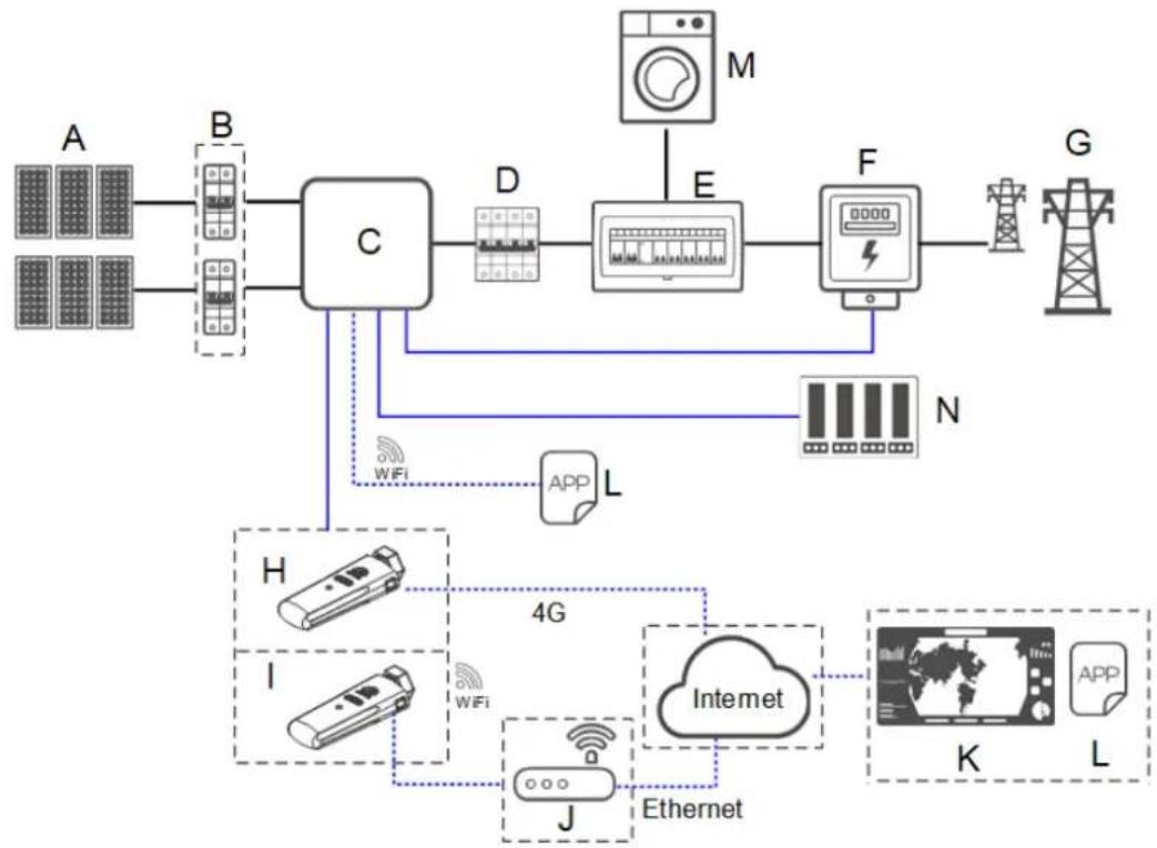
Figure 2-4 Appearance
(1) LED indicator
(2) Front panel
(3) Mounting plate
(4) Heat sink
(5) Ventilation valve
(6) Ground screw
(7) AC output port (AC)
(8) Communication port (COM)
(9) Smart Dongle port (GPRS/4G/WLAN)
(10) DC input terminals (PV4+/PV4−)
(11) DC input terminals (PV3+/PV3−)
(12) DC input terminals (PV2+/PV2−)
(13) DC input terminals (PV1+/PV1−)
(14) DC switch (DC SWITCH)

NOTE
Two M6 screw holes are reserved on the sides of the enclosure for installing an awning.
Table 2-2 LED indicator description
| Category | Status | Meaning | |
| Running indication | LED1 | LED2 | N/A |
| Steady green | Steady green | The SUN2000 is operating in grid-tied mode. | |
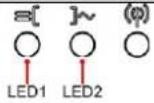 | Blinking green at long intervals (on for 1s and then off for 1s) | Off | The DC is on and the AC is off. |
| Blinking green at long intervals (on for 1s and then off for 1s) | Blinking green at long intervals (on for 1s and then off for 1s) | The DC is on, the AC is on, and the SUN2000 is not exporting power to the power grid. | |
| Off | Off | The DC is off.^a | |
| Blinking red at short intervals (on for 0.2s and then off for 0.2s) | N/A | DC environmental alarm | |
| N/A | Blinking red at short intervals (on for 0.2s and then off for 0.2s) | AC environmental alarm | |
| Steady red | Steady red | Fault | |
Communication indication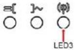 | LED3 | N/A | |
| Blinking green at short intervals (on for 0.2s and then off for 0.2s) | Communication is in progress.(When a mobile phone is connected to the SUN2000, the indicator first indicates that the phone is connected to the SUN2000): blinks green at long intervals.) | ||
| Blinking green at long intervals (on for 1s and then off for 1s) | The mobile phone is connected to the SUN2000. | ||
| Off | There is no communication. | ||
| Note a: The AC may be on. Check whether the external AC switch is OFF. | |||
2.3 Label Description
2.3.1 Enclosure Labels
| Symbol | Name | Meaning | |
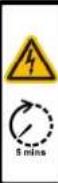 | Danger: High Voltage! 高压危险!Start maintaining the SUN2000 at least 5 minutes after the SUN2000 disconnects from all external power supplies.逆变器与外部所有电源断开后需要等待至少5分钟,才可以进行维护。 | Delayed discharge | Residual voltage exists after the SUN2000 is powered off. It takes 5 minutes for the SUN2000 to discharge to the safe voltage. |
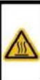 | Warning: High Temperature! 高温危险!Never touch the enclosure of an operating SUN2000.逆变器工作时严禁触摸外壳。 | Burn warning | Do not touch an operating SUN2000 because it generates high temperatures on the shell. |
 | Danger: Electrical Hazard!有电危险!Only certified professionals are allowed to install and operate the SUN2000.仅有资质的专业人员才可进行逆变器的安装和操作。High touch current, earth connection essential before connecting supply.大接触电流!接通电源前须先接地。 | Electric shock warning label | · High voltage exists after the SUN2000 is powered on. Only qualified and trained electrical technicians are allowed to perform operations on the SUN2000.· High touch current exists after the SUN2000 is powered on. Ensure that the SUN2000 has been grounded before powering on it. |
 | CAUTIONRead instructions carefully before performing any operation on the SUN2000.对逆变器进行任何操作前,请仔细阅读说明书! | Refer to documentation | Reminds operators to refer to the documents shipped with the SUN2000. |
 | Grounding | Indicates the position for connecting the protective earthing (PE) cable. | |
 | Do not disconnect under load!禁止带负荷断开连接! | Operation warning | Do not remove the DC input connector or the AC output connector when the SUN2000 is running. |
| [CHK] | XXXX000-XKTL-M0XXX MADE IN CHINA | SUN2000 serial number (SN) label | Indicates the SUN2000 SN. |
| Symbol | Name | Meaning |
 MAC: xxxxxxxxxxxx MAC: xxxxxxxxxxxx | SUN2000 MAC address label | Indicates the MAC address. |
 | QR code label for SUN2000 WiFi connection | Scan the QR code to connect to Huawei SUN2000 WiFi network. |
2.3.2 Product Nameplate
Figure 2-5 Nameplate (SUN2000-20KTL-M0 as an example)
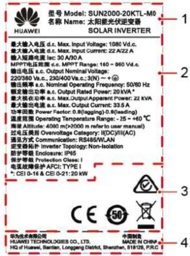
(1) Trademark and product model
(3) Compliance symbols
(2) Important technical specifications
(4) Company name and country of manufacture
NOTE
The nameplate figure is for reference only.
| Symbol | Name | Meaning |
 | Australia RCM certification mark | This product complies with Australia RCM certification standards. |
 | Conformité Europé enne (CE) certification mark | This product complies with CE certification standards. |
 | Environmentally friendly use period (EFUP) mark | The product does not pollute the environment during the specified period. |
 | EU waste electrical and electronic equipment (WEEE) mark | Do not dispose of the product as household garbage. |
2.4 Working Principles
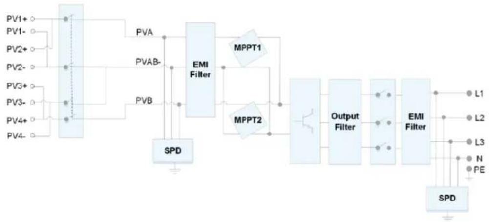
2.4.1 Circuit Diagram
Four PV strings connect to the SUN2000, and their maximum power points are tracked by two maximum power point tracking (MPPT) circuits. The SUN2000 converts DC power into three-phase AC power through an inverter circuit. Surge protection is supported on both the DC and AC sides.
Figure 2-6 SUN2000 conceptual diagram
flowchart
graph TD
    PV1+ --> EMI_Filter
    PV1- --> EMI_Filter
    PV2+ --> EMI_Filter
    PV2- --> EMI_Filter
    PV3+ --> EMI_Filter
    PV3- --> EMI_Filter
    PV4+ --> EMI_Filter
    PV4- --> EMI_Filter
    EMI_Filter --> MPPT1
    EMI_Filter --> MPPT2
    MPPT1 --> Output_Filter
    MPPT2 --> Output_Filter
    Output_Filter --> EMI_Filter
    EMI_Filter --> L1
    EMI_Filter --> L2
    EMI_Filter --> L3
    EMI_Filter --> N
    EMI_Filter --> PE
    SPD["SPD"] --> EMI_Filter
    PVA["PVA"] --> EMI_Filter
    PVAB-P["PVAB-"] --> EMI_Filter
    PVB["PVB"] --> EMI_Filter
    MPPT1 --> MPPT2
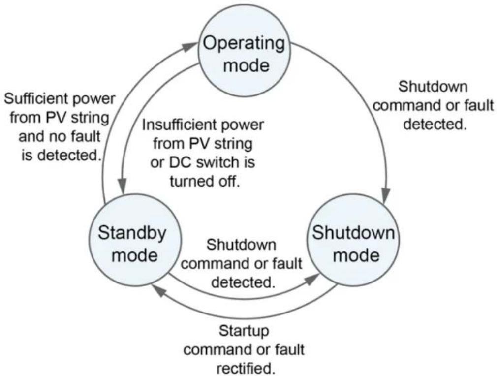
2.4.2 Working Modes
The SUN2000 can work in Standby, Operating, or Shutdown mode.
Figure 2-7 Working modes
flowchart
graph TD
    A["Operating mode"] -->|Insufficient power from PV string or DC switch is turned off.| B["Standby mode"]
    B -->|Sufficient power from PV string and no fault is detected.| A
    B -->|Shutdown command or fault rectified.| C["Shutdown mode"]
    C -->|Shutdown command or fault detected.| B
IS07S00001
Table 2-3 Working mode description
| Working Mode | Description |
| Standby | The SUN2000 enters Standby mode when the external environment does not meet the operating requirements. In Standby mode:· The SUN2000 continuously performs status check and enters the Operating mode once the operating requirements are met.· The SUN2000 enters Shutdown mode after detecting a shutdown command or a fault after startup. |
| Operating | In Operating mode:· The SUN2000 converts DC power from PV strings into AC power and feeds the power to the power grid.· The SUN2000 tracks the maximum power point to maximize the PV string output.· If the SUN2000 detects a fault or a shutdown command, it enters the Shutdown mode.· The SUN2000 enters Standby mode after detecting that the PV string output power is not suitable for connecting to the power grid for generating power. |
| Shutdown | In Standby or Operating mode, the SUN2000 enters Shutdown mode after detecting a fault or shutdown command.In Shutdown mode, the SUN2000 enters Standby mode after detecting a startup command or that the fault is rectified. |
3 Storage
The following requirements should be met if the SUN2000 is not put into use directly:
• Do not unpack the SUN2000.
- Keep the storage temperature at -40^ to +70^ and the humidity at 5% -95% RH (non-condensing).
- The SUN2000 should be stored in a clean and dry place and be protected from dust and water vapor corrosion.
- A maximum of six SUN2000s can be stacked. To avoid personal injury or device damage, stack SUN2000s with caution to prevent them from falling over.
- Periodic inspections are required during the storage. Replace the packing materials if necessary.
- If the SUN2000 has been long-term stored, inspections and tests should be conducted by qualified personnel before it is put into use.
4 Installation
4.1 Checking Before Installation
Outer Packing Materials
Before unpacking the inverter, check the outer packing materials for damage, such as holes and cracks, and check the inverter model. If any damage is found or the inverter model is not what you requested, do not unpack the package and contact your supplier as soon as possible.
NOTE
You are advised to remove the packing materials within 24 hours before installing the inverter.
Package Contents
After unpacking the inverter, check that the contents are intact and complete. If any damage is found or any component is missing, contact your supplier.
NOTE
For details about the number of contents, see the Packing List in the packing case.
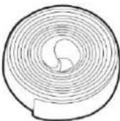
4.2 Tools
| Type | Tool | |||
| Installation Tools | 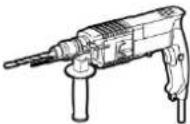 | 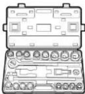 | 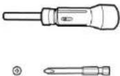 | 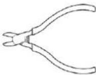 |
| Hammer drill Drill bit: Φ8 mm and Φ6 mm | Socket wrench set | Torque screwdriver Phillips head: M3 | Diagonal pliers | |
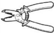 Wire stripper Wire stripper | 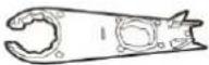 Removal wrenchModel:H4TW0001;manufacturer:Amphenol Removal wrenchModel:H4TW0001;manufacturer:Amphenol | 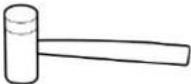 Rubber mallet Rubber mallet | 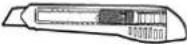 Utility knife Utility knife | |
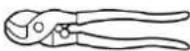 Cable cutter Cable cutter | 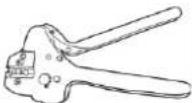 Crimping toolModel:H4TC0003;manufacturer:Amphenol Crimping toolModel:H4TC0003;manufacturer:Amphenol | 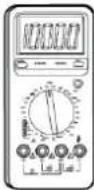 MultimeterDC voltage measurement range ≥ 1100 V DC MultimeterDC voltage measurement range ≥ 1100 V DC | 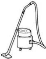 Vacuum cleaner Vacuum cleaner | |
 Marker Marker | 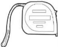 Measuring tape Measuring tape | 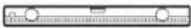 Bubble or digital level Bubble or digital level | 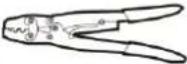 OT terminal crimping tool OT terminal crimping tool | |
 Heat shrink tubing Heat shrink tubing | 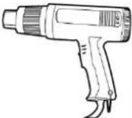 Heat gun Heat gun |  Cable tie Cable tie | N/A | |
| PPE |  Safety gloves Safety gloves | 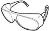 Safety goggles Safety goggles | 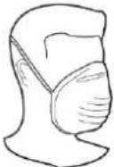 Anti-dust respirator Anti-dust respirator |  Safety shoes Safety shoes |
4.3 Determining the Installation Position
4.3.1 Environment Requirements
Basic Requirements
- The SUN2000 is protected to IP65 and can be installed indoors or outdoors.
- Do not install the SUN2000 in a place where personnel are easy to come into contact with its enclosure and heat sinks, because these parts are extremely hot during operation.
- Do not install the SUN2000 in areas with flammable or explosive materials.
- Do not install the SUN2000 at a place within children's reach.
- Do not install the SUN2000 outdoors in salt areas because it will be corroded there and may cause fire. A salt area refers to the region within 500 meters from the coast or prone to sea breeze. The regions prone to sea breeze vary depending on weather conditions (such as typhoons and monsoons) or terrains (such as dams and hills).
- The SUN2000 must be installed in a well-ventilated environment to ensure good heat dissipation.
- Recommended: Install the SUN2000 in a sheltered place or a place with an awning.
Mounting Structure Requirements
- The mounting structure where the SUN2000 is installed must be fireproof.
- Do not install the SUN2000 on flammable building materials.
- The SUN2000 is heavy. Ensure that the installation surface is solid enough to bear the weight load.
- In residential areas, do not install the SUN2000 on drywalls or walls made of similar materials which have a weak sound insulation performance because the noise generated by the SUN2000 is noticeable.
4.3.2 Space Requirements
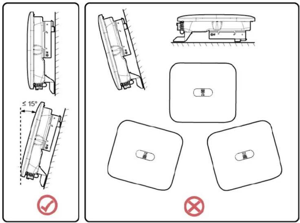
Installation Angle Requirements
The SUN2000 can be wall-mounted or pole-mounted. The installation angle requirements are as follows:
- Install the SUN2000 vertically or at a maximum back tilt of 15 degrees to facilitate heat dissipation.
- Do not install the SUN2000 at forward tilted, excessive back tilted, side tilted, horizontal, or upside down positions.
Figure 4-1 Installation tilts
IS10H00012
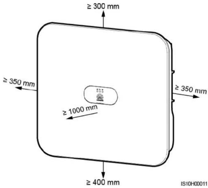
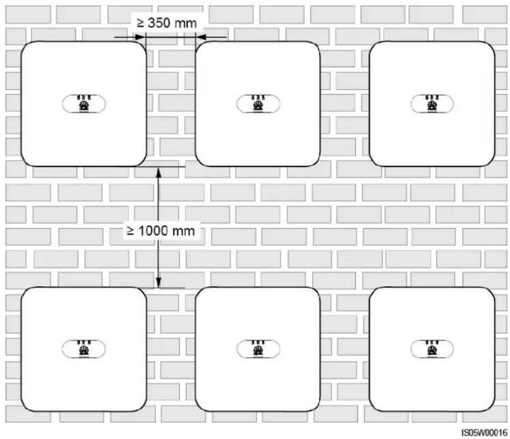
Installation Space Requirements
- Reserve enough space around the SUN2000 to ensure sufficient space for installation and heat dissipation.
Figure 4-2 Installation space
- When installing multiple SUN2000s, install them in horizontal mode if sufficient space is available and install them in triangle mode if no sufficient space is available. Stacked installation is not recommended.
Figure 4-3 Horizontal installation (recommended)
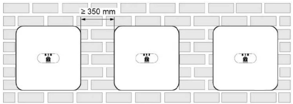
IS10H00014
Figure 4-4 Staggered installation (recommended)
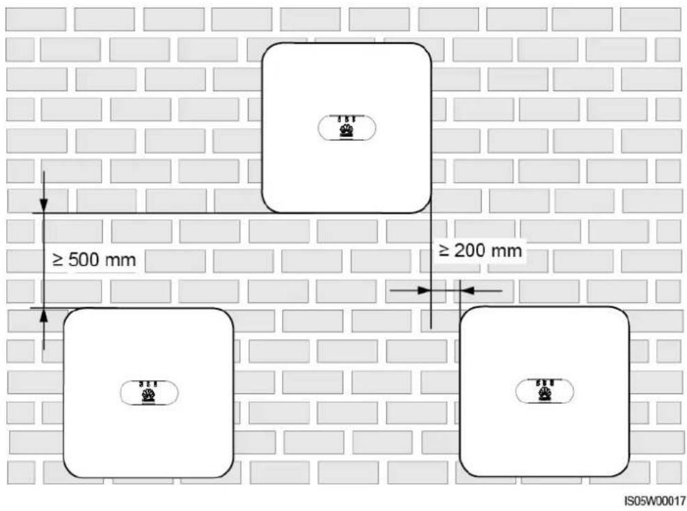
Figure 4-5 Stacked installation (not recommended)
4.4 Moving an Inverter
Procedure
Step 1 Two persons are required to move the inverter and one person on both sides. Lift the inverter from the packing case and move it to the specified installation position.
CAUTION
- To prevent personal injury and damage to the device, take care to keep your balance when moving the SUN2000.
- Do not use the wiring terminals and ports at the bottom to support any weight of the SUN2000.
- When you need to temporally place the SUN2000 on the ground, use foam, paper or other protective materials to prevent damage to its enclosure.
Figure 4-6 Moving an inverter
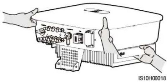
natural_image
Illustration of hands operating a device with ports and connectors (no text or symbols visible)----End
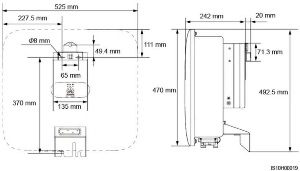
4.5 Installing the Mounting Bracket
Installation Precautions
Figure 4-7 shows the dimensions of installation holes on the SUN2000.
Figure 4-7 Mounting bracket dimensions
4.5.1 Wall-mounted Installation
Procedure
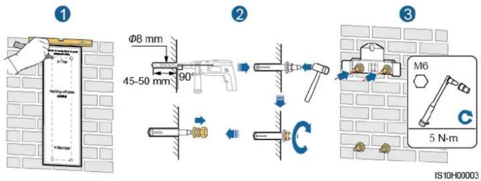
Step 1 Determine the installation positions for drilling holes, and mark the positions using a marker.
Step 2 Secure the mounting brackets.

NOTE
- M6x60 expansion bolts are delivered with the SUN2000. If the length and amount of the bolts do not meet installation requirements, prepare M6 stainless steel expansion bolts by yourself.
- The expansion bolts delivered with the inverter are used for solid concrete walls. For other types of walls, prepare bolts by yourself and ensure that the wall meets the load bearing requirements of the inverter.
Figure 4-8 Expansion bolt composition
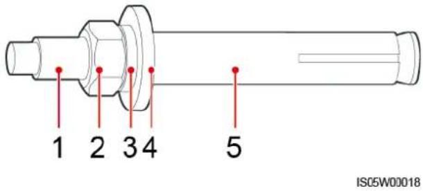
(1) Bolt
(2) Nut
(3) Spring washer
(4) Flat washer
(5) Expansion tube
DANGER
Avoid drilling holes in the utility pipes or cables attached to the back of the wall.
NOTICE
- To prevent dust inhalation or contact with eyes, wear safety goggles and an anti-dust respirator when drilling holes.
- Clean up any dust in and around the holes using a vacuum cleaner and measure the distance between holes. If large hole tolerance exists, position and drill holes again.
- After removing the bolt, spring washer, and flat washer, level the front of the expansion tube with the concrete wall. Otherwise, the mounting brackets will not stay steady on the concrete wall.
- Partially loosen the nut, flat washer and spring washer of the two expansion bolts below.
Figure 4-9 Installing the Mounting Bracket
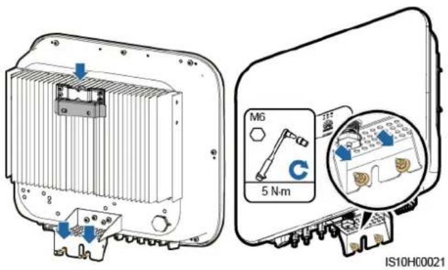
Step 3 Install the SUN2000 onto the mounting bracket.
Step 4 Tighten nuts.
Figure 4-10 Installing the SUN2000
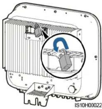
Step 5 (Optional) Install the anti-theft lock.
NOTICE
- Prepare an anti-theft lock suitable for the lock hole diameter (Φ8 mm) by yourself.
- An outdoor waterproof lock is recommended.
- Keep the key to the anti-theft lock safe.
Figure 4-11 Installing the anti-theft lock
natural_image
Diagram of an electronic device showing internal components and a magnified inset of a device (no text or symbols present)---End
4.5.2 Support-mounted Installation
Prerequisites
Prepare M6 stainless bolt assemblies (including flat washers, spring washers, and M6 bolts) with appropriate lengths as well as matched flat washers and nuts based on the support specifications.
Procedure
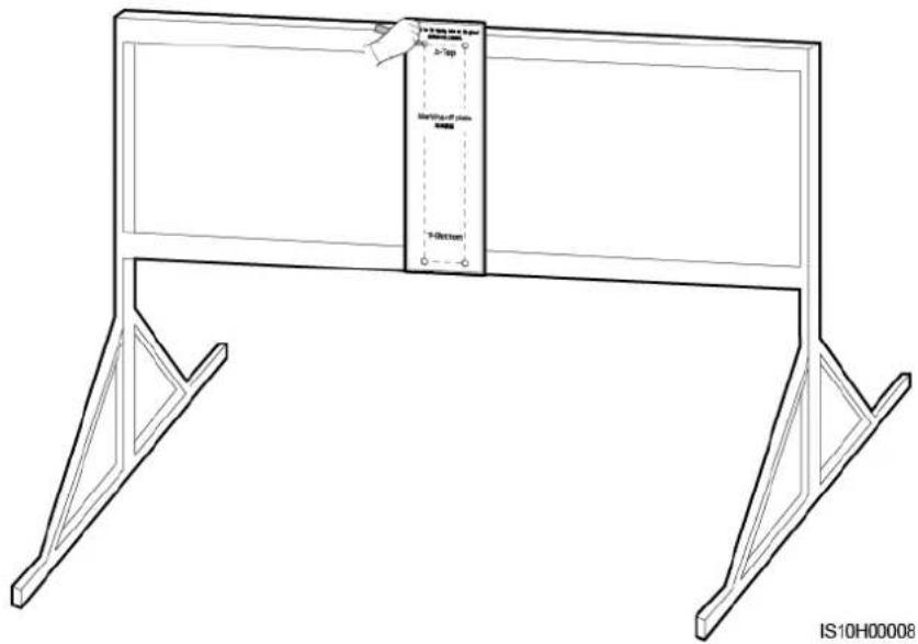
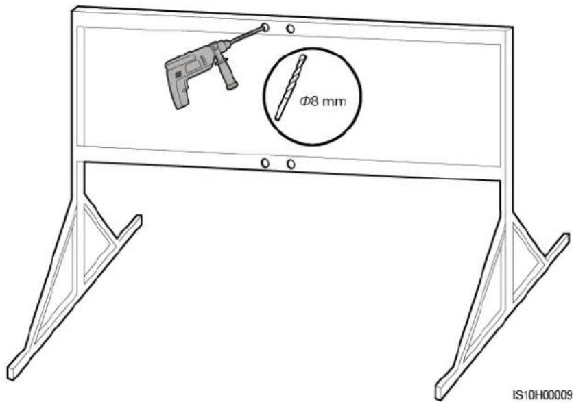
Step 1 Determine the hole positions based on the marking-off template, and then mark the hole positions using a marker.
Figure 4-12 Determining hole positions
Step 2 Drill holes using a hammer drill.

NOTE
You are advised to apply anti-rust paint on the hole positions for protection.
Figure 4-13 Drilling holes
Step 3 Secure the mounting bracket.
Figure 4-14 Securing the mounting bracket

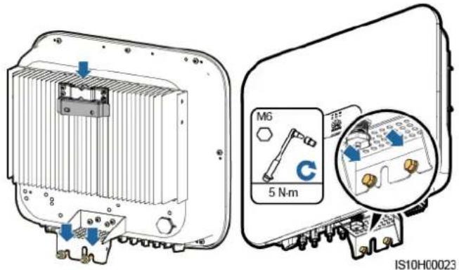
Step 4 Install the SUN2000 onto the mounting bracket.
Step 5 Tighten the bolt assembly.
Figure 4-15 Installing the SUN2000
Step 6 (Optional) Install the anti-theft lock.
NOTICE
- Prepare an anti-theft lock suitable for the lock hole diameter (Φ8 mm) by yourself.
- An outdoor waterproof lock is recommended.
- Keep the key to the anti-theft lock safe.
Figure 4-16 Installing the anti-theft lock
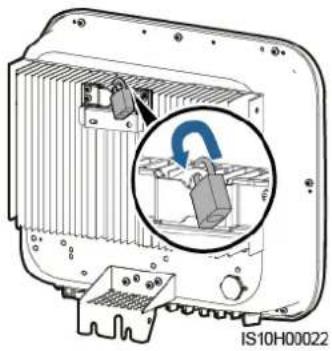
natural_image
Interior view of an electronic device showing a component with a magnified inset highlighting a blue circular feature (no text or symbols visible)----End
5 Electrical Connections
Precautions
DANGER
Before connecting cables, ensure that the DC switch on the SUN2000 and all the switches connecting to the SUN2000 are OFF. Otherwise, the high voltage of the SUN2000 may result in electric shocks.
WARNING
- The equipment damage caused by incorrect cable connections is beyond the warranty scope.
- Only certified electricians are allowed to connect cables.
- Operation personnel must wear proper PPE when connecting cables.
NOTE
The cable colors shown in the electrical connection diagrams provided in this chapter are for reference only. Select cables in accordance with local cable specifications (green-and-yellow cables are only used for PE).
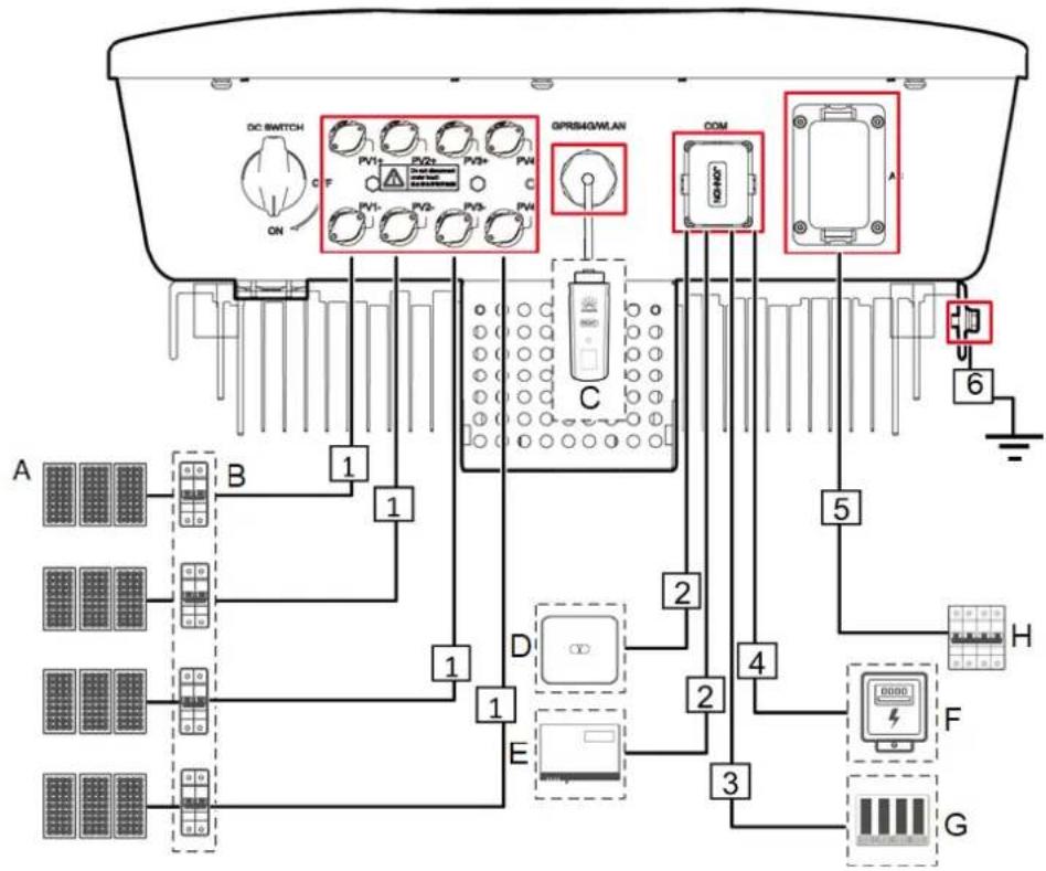
5.1 Preparing for Installation
Figure 5-1 SUN2000 cable connections (optional in dashed boxes)
flowchart
graph TD
    A["DC SWITCH"] --> B["1"]
    B --> C["2"]
    C --> D["3"]
    D --> E["4"]
    E --> F["5"]
    F --> G["6"]
    G --> H["7"]
    H --> I["8"]
    I --> J["9"]
    J --> K["10"]
    K --> L["11"]
    L --> M["12"]
    M --> N["13"]
    N --> O["14"]
    O --> P["15"]
    P --> Q["16"]
    Q --> R["17"]
    R --> S["18"]
    S --> T["19"]
    T --> U["20"]
    U --> V["21"]
    V --> W["22"]
    W --> X["23"]
    X --> Y["24"]
    Y --> Z["25"]
    Z --> AA["26"]
    AA --> AB["27"]
    AB --> AC["28"]
    AC --> AD["29"]
    AD --> AE["30"]
    AE --> AF["31"]
    AF --> AG["32"]
    AG --> AH["33"]
    AH --> AI["34"]
    AI --> AJ["35"]
    AJ --> AK["36"]
    AK --> AL["37"]
    AL --> AM["38"]
    AM --> AN["39"]
    AN --> AO["40"]
    AO --> AP["41"]
    AP --> AQ["42"]
    AQ --> AR["43"]
    AR --> AS["44"]
    AS --> AT["45"]
    AT --> AU["46"]
    AU --> AV["47"]
    AV --> AW["48"]
    AW --> AX["49"]
    AX --> AY["50"]
NOTICE
If the Smart Dongle is configured, you are advised to install the Smart Dongle before connecting the signal cable.
Table 5-1 Component description
| No. | Component | Description | Source |
| A | PV module | A PV string is composed of the PV modules connected in series.The SUN2000 supports the input from four PV strings. | Prepared by the customer |
| B | DC switch | Recommended: a PV circuit breaker with a rated voltage greater than or equal to 1,100 V DC and a rated current of 15 A. | Prepared by the customer |
| C | Smart Donglea | WLAN Smart Dongle: SDongleA-01.4G Smart Dongle: SDongleA-03. | Purchased from Huawei |
| D | SUN2000 | Select a proper model based on requirements. | Purchased from Huawei |
| E | SmartLogger10 00A | Select a proper model based on requirements. | Purchased from Huawei |
| F | Smart Power Sensor | The recommended electricity meter model is DTSU666-H. | Purchased from Huawei |
| G | Ripple Control Device | Select the devices that meet the power grid scheduling requirements. | Provided by local power grid companies |
| H | AC switchb | Recommended: a three-phase AC circuit breaker with a rated voltage greater than or equal to 415 V AC and a rated current of:25 A (SUN2000-8KTL-M0, SUN2000-10KTL-M0, SUN2000-12KTL-M0)40 A (SUN2000-15KTL-M0, SUN2000-17KTL-M0, SUN2000-20KTL-M0) | Prepared by the customer |
| Note a: WLAN Smart Dongle: For details about the SDongleA-01 operation, see SDongleA-01 Quick Guide (WLAN); 4G Smart Dongle: For details about the SDongleA-03 operation, see SDongleA-03 Quick Guide (4G). You can obtain the quick guide at https://support.huawei.com/enterprise by searching for the Smart Dongle model.Note b: The SUN2000-8KTL-M0 and SUN2000-10KTL-M0 inverters are applicable only to Australia. | |||
Table 5-2 Cable description
| No. | Name | Type | Specifications |
| 1 | DC input power cable | Standard PV cable in the industry | Conductor cross-sectional area: 4–6 mm2Cable outer diameter: 4.5–7.8 mm |
| 2 | (Optional) RS485 communications cable (used to cascade inverters or connect to the RS485 signal port on the SmartLogger) | Two-core outdoor shielded twisted pair cable | Conductor cross-sectional area: 0.2-1 mm2Cable outer diameter: 4-11 mm |
| 3 | (Optional) RS485 communications cable (used to connect to the RS485 signal port on a Smart Power Sensor for export limitation) | Two-core outdoor shielded twisted pair cable | Conductor cross-sectional area: 0.2-1 mm2Cable outer diameter: 4-11 mm |
| 4 | (Optional) Grid scheduling signal cable | Five-core outdoor cable | Conductor cross-sectional area: 0.2-1 mm2Cable outer diameter: 4-11 mm |
| 5 | AC output power cable | Outdoor copper cablea | SUN2000-8KTL-M0, SUN2000-10KTL-M0, SUN2000-12KTL-M0:Conductor cross-sectional area: 6-16 mm2Cable outer diameter: 11-26 mm |
| SUN2000-15KTL-M0, SUN2000-17KTL-M0, SUN2000-20KTL-M0:Conductor cross-sectional area: 10-16 mm2Cable outer diameter: 11-26 mm | |||
| 6 | PE cable | Single-core outdoor copper cableb | SUN2000-8KTL-M0, SUN2000-10KTL-M0, SUN2000-12KTL-M0: Conductor cross-sectional area ≥ 6 mm2 |
| SUN2000-15KTL-M0, SUN2000-17KTL-M0, SUN2000-20KTL-M0: Conductor cross-sectional area ≥ 10 mm2 | |||
| Note a: The SUN2000-8KTL-M0 and SUN2000-10KTL-M0 inverters are applicable only to Australia.Note b: The SUN2000-8KTL-M0 and SUN2000-10KTL-M0 inverters are applicable only to Australia. | |||
5.2 Connecting the PE cable
Precautions
DANGER
- Ensure that the PE cable is properly connected. If it is disconnected or loose, electric shocks may occur.
- Do not connect the neutral wire to the enclosure as a PE cable. Otherwise, electric shocks may occur.
NOTE
- The PE point at the AC output port is used only as a PE equipotential point, and cannot substitute for the PE point on the enclosure.
- After the ground cable is installed, it is recommended that the silica gel or paint be applied to the ground terminal for protection.
Additional Information
The SUN2000 has the grounding detection function. This function detects whether the SUN2000 is grounded properly before its startup, or whether the ground cable is disconnected when the SUN2000 is running. This function works under limited conditions. To ensure the safe operation of the SUN2000, ground the SUN2000 properly according to the connection requirements of the PGND cable. For some power grid types, if the output side of the inverter is connected to an isolation transformer, ensure that the inverter is properly grounded and set isolation settings to Input not grounded, with a transformer to enable the inverter to run properly.
- According to IEC62109, to ensure safe application in case of the ground cable is damaged or disconnected, connect the PE cable properly before the grounding detection function is disabled. Ensure that the PE cable meets at least one of the following requirements.
- The PE cable is a single-core outdoor copper cable with a conductor cross-sectional area of at least 10mm^2 .
- Use cables that have the same diameter as the AC output cable, and ground the PE terminal on the AC connector and the ground screw on the enclosure respectively.
- In some countries and regions, additional ground cables are required for the SUN2000. In this case, use cables that have the same diameter as the AC output cable, and ground the PE terminal on the AC connector and the ground screw on the enclosure respectively.
Procedure
Step 1 Crimp the OT terminal.
NOTICE
- Pay attention not to damage the core wire when stripping a cable.
- The cavity formed after crimping the conductor strip of the OT terminal needs to wrap the core wire completely. The core wire needs to contact the OT terminal closely.
- Wrap the wire crimping area with the heat shrink tubing or the PVC insulation tape. The following figure uses the heat shrink tubing as an example.
- When using the heat gun, protect devices from being scorched.
Figure 5-2 Crimping an OT terminal
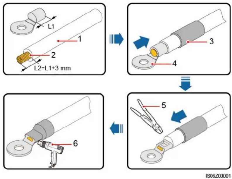
(1) Cable
(4) OT terminal
(2) Core wire
(5) Crimping tool
(3) Heat shrink tubing
(6) Heat gun
Step 2 Connect the PE cable.
Figure 5-3 Connecting the PE cable
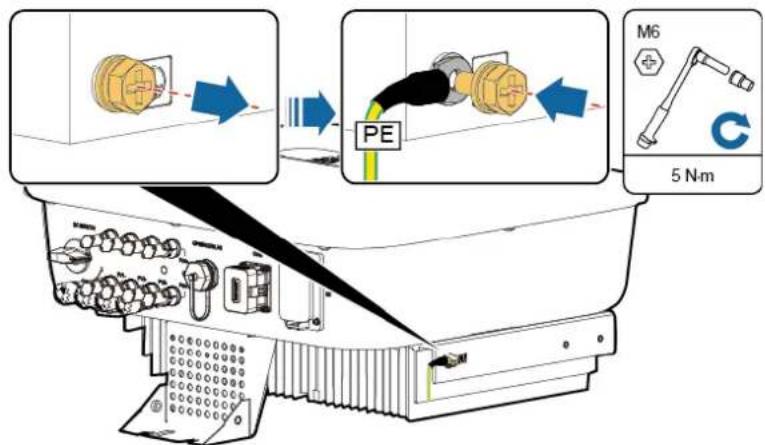
IS10I10001
----End
5.3 Connecting the AC Output Power Cable
Precautions
A three-phase AC switch needs to be installed on the AC side of the SUN2000. To ensure that the SUN2000 can safely disconnect itself from the power grid when an exception occurs, select a proper overcurrent protection device in compliance with local power distribution regulations.
Do not connect loads between the SUN2000 and the AC switch directly connected to it.
The SUN2000 is integrated with a comprehensive residual current monitoring unit. Once detecting that the residual current exceeds the threshold, the SUN2000 immediately disconnects itself from the power grid.
NOTICE
- If the external AC switch can perform earth leakage protection, the rated leakage action current should be greater than or equal to 100 mA.
- If multiple SUN2000s connect to the general residual current device (RCD) through their respective external AC switches, the rated leakage action current of the general RCD should be greater than or equal to the number of SUN2000s multiplied by 100 mA.
- A knife switch cannot be used as an AC switch.
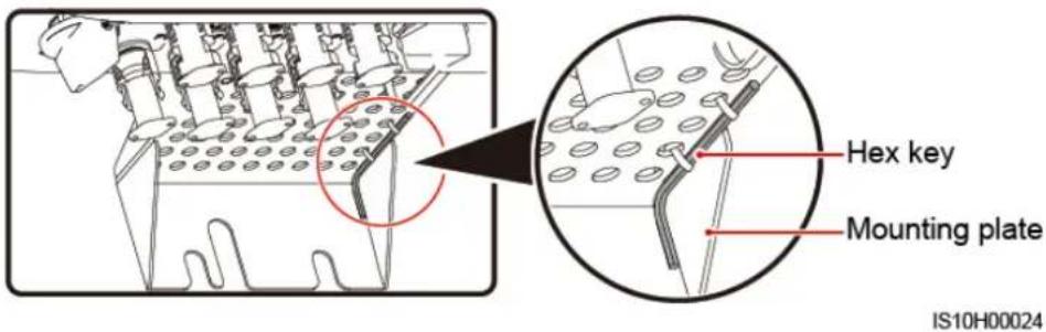
- The hex key is delivered with the inverter and bound to the hanging kit at the bottom of the inverter.
Figure 5-4 Hex key
Procedure
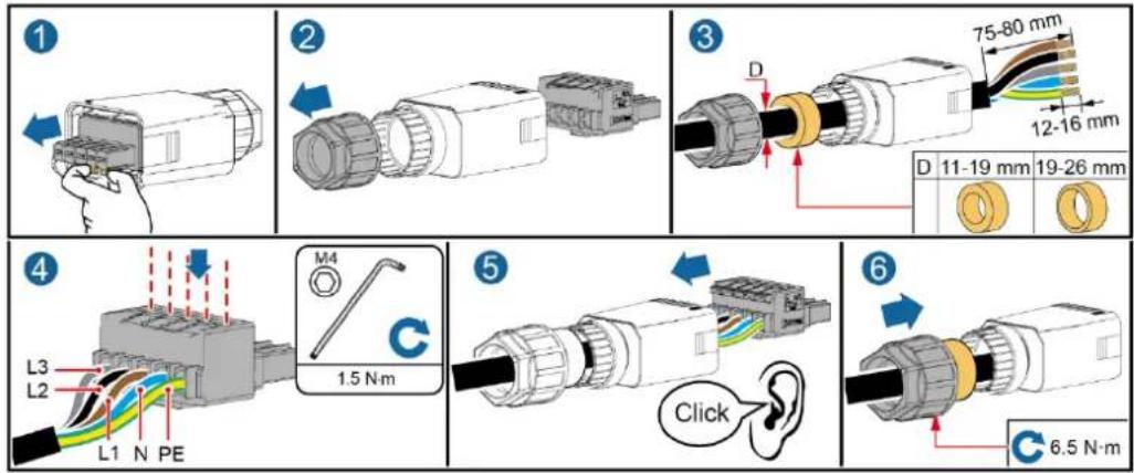
Step 1 Connect the AC output power cable to the AC connector.
Figure 5-5 Stripping requirements
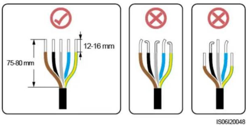
NOTICE
- Ensure that the cable jacket is inside the connector.
- Ensure that the exposed core wire is totally inserted into the cable hole.
- Ensure that AC terminations provide firm and solid electrical connections. Failing to do so may cause SUN2000 malfunction and damage to its AC connectors.
- Ensure that the cable is not twisted.
Figure 5-6 Three-core cable (L1, L2, and L3)
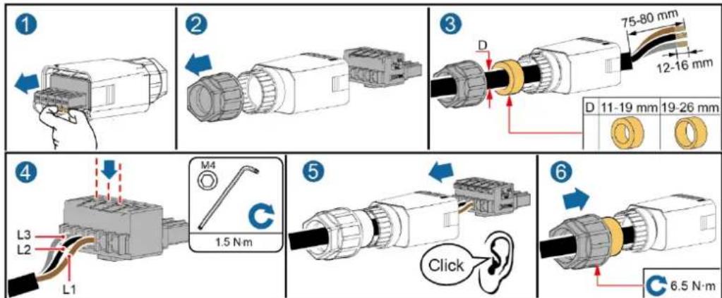
IS10I20016
Figure 5-7 Four-core cable (L1, L2, L3, and PE)
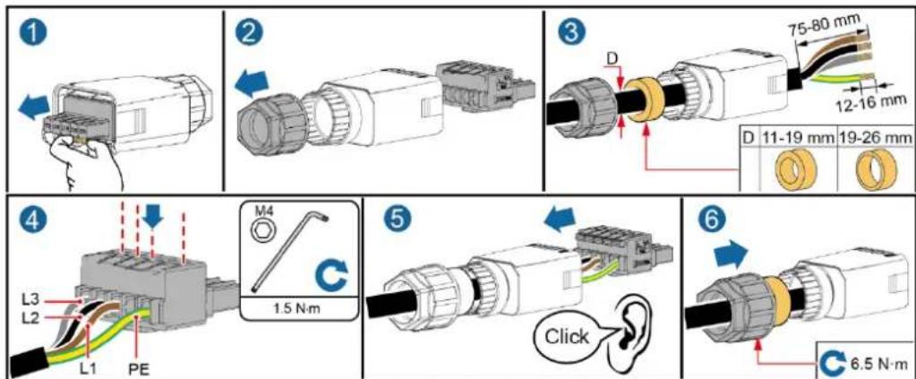
IS10I20015
Figure 5-8 Four-core cable (L1, L2, L3, and N)
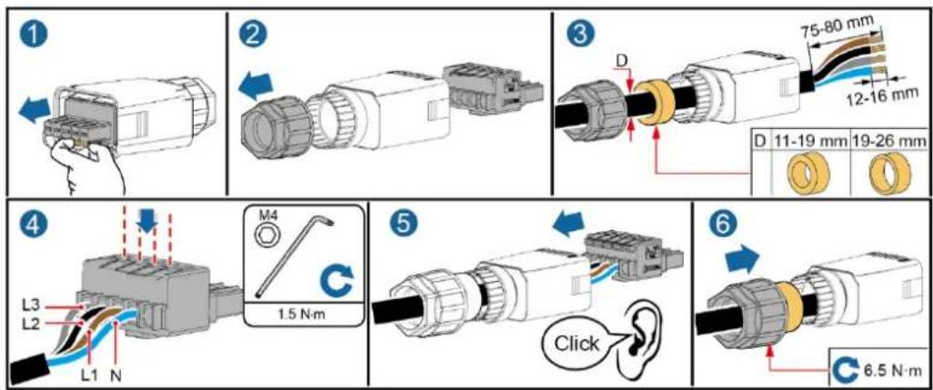
IS10I20014
Figure 5-9 Five-core cable (L1, L2, L3, N, and PE)
IS10I20013
NOTE
The cable colors shown in the figures are for reference only. Select an appropriate cable according to local standards.
Step 2 Connect the AC connector to the AC output port.
NOTICE
Ensure that the AC connector is connected securely.
Figure 5-10 Securing the AC connector
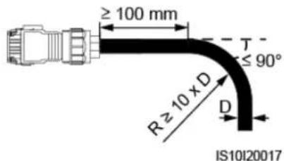
Step 3 Check the route of the AC output power cable.
Figure 5-11 Cable route
----End
Disconnection
Disconnection can be performed in reverse order.
5.4 Connecting the DC input power cable
Precautions
DANGER
- Before connecting the DC input power cable, ensure that the DC voltage is within the safe range (lower than 60 V DC), and that the DC SWITCH is set to the OFF position. Failure to do so could generate high voltage, which may cause electric shocks.
- When the SUN2000 is operating, it is not allowed to operate the DC input power cable, such as connecting or disconnecting a PV string or a PV module in a PV string. Failing to do so may cause electric shocks.
- If no PV string is connected to a DC input terminal of the SUN2000, do not remove the watertight cap from the terminal. Otherwise, the IP rating of the SUN2000 will be affected.
WARNING
Ensure that the following conditions are met. Otherwise, the SUN2000 may be damaged, or even a fire could happen.
- PV modules connected in series in each PV string are of the same specifications.
- The open-circuit voltage of each PV string is always lower than or equal to 1080 V DC.
- The maximum short-circuit current of each PV string must be lower than or equal to 15 A.
- The DC input power cable is correctly connected. The positive and negative terminals of a PV module are connected to corresponding positive and negative DC input terminals of the SUN2000.
- If the DC input power cable is reversely connected, do not operate the DC switch and positive and negative connectors. Wait until the solar irradiance declines at night and the PV string current reduces to below 0.5 A, and then turn off the DC switch. Remove the positive and negative connectors to correct the polarity.
NOTICE
- Because the output of the PV string connected to the SUN2000 cannot be grounded, ensure that the PV module output is insulated to ground.
- The PV strings connecting to the same MPPT circuit should contain PV modules of the same model and quantity.
- During the installation of PV strings and the SUN2000, the positive or negative terminals of PV strings may be short-circuited to ground if power cables are not properly installed or routed. An AC or DC short circuit may occur and damage the device when the SUN2000 is operating. The caused device damage is not covered under any warranty.
Terminal Description
Figure 5-12 Terminals
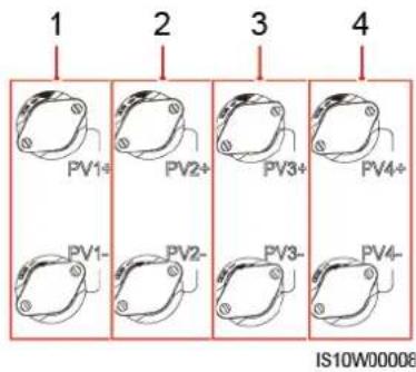
(1) Terminals of DC input 1
(2) Terminals of DC input 2
(3) Terminals of DC input 3
(4) Terminals of DC input 4

NOTE
It is recommended that the number of PV modules connected to PV1 and PV2 be the same, and that the number of PV modules connected to PV3 and PV4 be the same.
Procedure
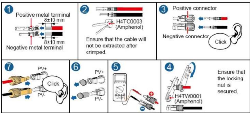
Step 1 Connect the DC input power cable.

WARNING
Before inserting the positive and negative connectors into the positive and negative DC input terminals of the SUN2000, check that the DC SWITCH is OFF.
CAUTION
Use the Amphenol Helios H4 PV connectors supplied with the SUN2000. If the PV connectors are lost or damaged, purchase the connectors of the same model. The device damage caused by incompatible PV connectors is not covered under any warranty.
NOTICE
- Cables with high rigidity, such as armored cables, are not recommended as DC input power cables, because poor contact may be caused by the bending of the cables.
- Before assembling DC connectors, label the cable polarities correctly to ensure correct cable connections.
- After crimping the positive and negative metal contacts, pull the DC input power cables back to ensure that they are connected securely.
- Insert the crimped metal contacts of the positive and negative power cables into the appropriate positive and negative connectors. Then pull back the DC input power cables to ensure that they are connected securely.
- Crimp the metal stamping forming contacts using crimping tool H4TC0003 (Amphenol, recommended), H4TC0002 (Amphenol), PV-CZM-22100 (Staubli), or PV-CZM-19100 (Staubli). When choosing PV-CZM-22100 or PV-CZM-19100, do not use the locator. Otherwise metal contacts would be damaged.
Figure 5-13 Crimping tool (H4TC0003)
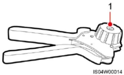
(1) Locator
NOTE
- The DC voltage measurement range of the multimeter must be at least 1100 V.
- If the voltage is a negative value, the DC input polarity is incorrect and needs correction.
- If the voltage is greater than 1080 V, too many PV modules configured in the same string. Remove some PV modules.
Figure 5-14 Connecting the DC input power cable
IS10I30003
NOTICE
If the DC input power cable is reversely connected and the DC SWITCH is set to the ON position, do not operate the DC SWITCH and positive and negative connectors. Otherwise, the device may be damaged. The caused device damage is not covered under any warranty. Wait until the solar irradiance declines and the PV string current drops to below 0.5 A. Then set the two DC SWITCH to the OFF position, remove the positive and negative connectors, and rectify the connection of the DC input power cable.
----End
Removing a DC connector
WARNING
Before removing the positive and negative connectors, ensure that the DC SWITCH is OFF.
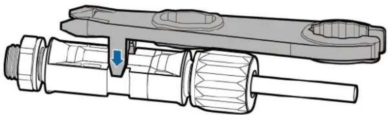
To remove the positive and negative connectors from the SUN2000, insert an open-end wrench into the notch and press hard to remove the DC connector.
Figure 5-15 Removing a DC connector
natural_image
Technical illustration of a mechanical assembly with threaded components and a blue arrow indicating a specific part (no text or symbols present)ISO1IC0042
5.5 (Optional) Installing the Smart Dongle
Procedure

NOTE
- If the 4G Smart Dongle you purchase is configured with a SIM card, skip this step.
- If it is not configured with a SIM card, prepare a standard one (dimensions: 25 mm x 15 mm, capacity ≥ 64 KB.
- When installing a SIM card, you can determine the SIM card installation direction based on the silk screen and arrow mark on the slot.
- When being pressed into place, the SIM card will be locked, which means that the card is installed correctly.
• To remove the SIM card, push it inwards. Then the SIM card springs out automatically. - When reinstalling the 4G Smart Dongle, ensure that the buckle springs back in place.
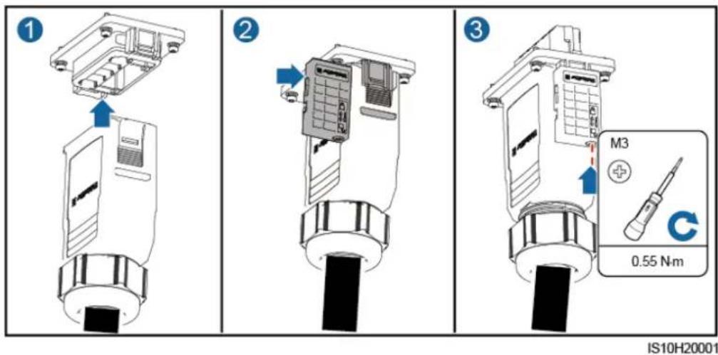
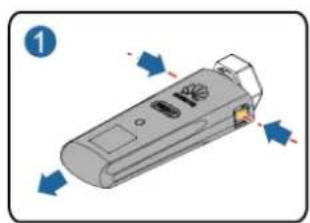
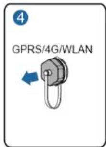
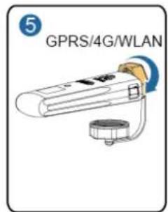
Step 1 Install the Smart Dongle.
Figure 5-16 Installing the Smart Dongle.
natural_image
Illustration of a handheld electronic device with directional arrows indicating rotation (no text or symbols)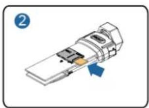
natural_image
Diagram of a device with an arrow indicating a component or process, no visible text or symbols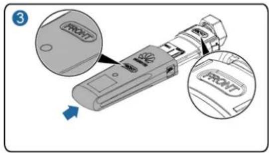
IS10H00016
----End
5.6 (Optional) Installing the Signal Cable
Communication port signal definitions
NOTICE
- When routing the signal cable, ensure that it is separate from the power cable and away from interfering sources to prevent communication from being affected.
- The protection layer of the cable is in the connector. Cut off surplus core wires from the protection layer. Ensure that the core wires are completely inserted into the cable holes, and that the cable is securely connected.
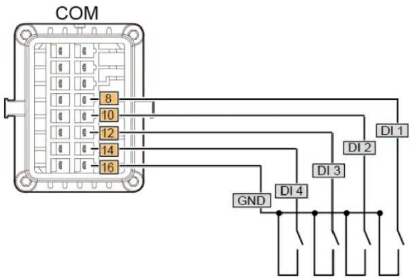
Figure 5-17 Signal definitions
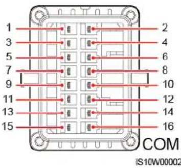
Table 5-3 Signal definitions
| Pin | Definition | Function | Description | Pin | Definition | Function | Description |
| 1 | 485A1-1 | RS485 differential signal+ | Used to connect to the RS485 signal port on the SUN200 0 or SmartLogger100 0A | 2 | 485A1-2 | RS485 differential signal+ | Used to connect to the RS485 signal port on the SUN200 0 or SmartLogger100 0A |
| 3 | 485B1-1 | RS485 differential signal- | 4 | 485B1-2 | RS485 differential signal- | ||
| 5 | PE | Shielding ground | N/A | 6 | PE | Shielding ground | N/A |
| 7 | 485A2 | RS485 differential signal+ | Used to connect to an RS485 | 8 | DIN1 | Dry contact interface for grid | Connects to the Ripple Control |
| 9 | 485B2 | RS485 differential signal- | signal port on a Smart Power Sensor for export limitation | 10 | DIN2 | scheduling | Device. |
| 11 | N/A | N/A | N/A | 12 | DIN3 | ||
| 13 | GND | Signal ground | N/A | 14 | DIN4 | ||
| 15 | N/A | N/A | N/A | 16 | GND |
Communication Networking
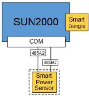
• Single Inverter+Smart Dongle Networking
Figure 5-18 Smart Dongle networking
flowchart
graph TD
    A["SUN2000"] --> B["COM"]
    B --> C["485A2"]
    B --> D["485B2"]
    C --> E["Smart Power Sensor"]
    D --> E
    F["Smart Dongle"] --> A

NOTE
- In the Smart Dongle networking scenario, the SmartLogger1000A cannot be connected.
- The Smart Power Sensor is necessary for export limitation. Only the DTSU666-H Smart Power Sensor (provided by Huawei) can be used.
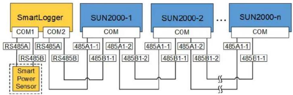
• Multiple Inverters+SmartLogger1000A Networking
Figure 5-19 SmartLogger networking
flowchart
graph TD
    A["SmartLogger"] --> B["COM1"]
    A --> C["COM2"]
    B --> D["RS485A"]
    C --> E["RS485A"]
    D --> F["RS485B"]
    E --> G["RS485B"]
    F --> H["Smart Power Sensor"]
    G --> I["RS485B"]
    J["SUN2000-1"] --> K["COM"]
    J --> L["COM"]
    K --> M["485A1-1"]
    K --> N["485A1-2"]
    L --> O["485B1-1"]
    L --> P["485B1-2"]
    M --> Q["485A1-1"]
    M --> R["485A1-2"]
    N --> S["485B1-1"]
    N --> T["485B1-2"]
    O --> U["485B1-2"]
    P --> V["..."]
    Q --> W["485A1-1"]
    R --> X["485A1-2"]
    S --> Y["485B1-1"]
    T --> Z["485B1-2"]
    U --> AA["SUN2000-2"]
    V --> AB["SUN2000-n"]
    W --> AC["SUN2000-n"]
    X --> AD["SUN2000-n"]
    Y --> AE["SUN2000-n"]
    Z --> AF["SUN2000-n"]
NOTE
• In the SmartLogger1000A networking scenario, the Smart Dongle cannot be connected.
- A maximum of 80 devices can connect to a single SmartLogger1000A, such as inverters, Smart Power sensor, and EMI. You are advised to connect fewer than 30 devices to each RS485 route.
- The Smart Power Sensor is a necessary export limitation. Select the Smart Power Sensor according to the actual project.
- To ensure the system response speed, the Smart Power Sensor is recommended to be connected to a COM port separately from inverter COM port.
5.6.1 Connecting the RS485 Communications Cable (Inverter Cascading)
Procedure
Step 1 Connect the signal cable to the signal cable connector.
Figure 5-20 Installing the cable
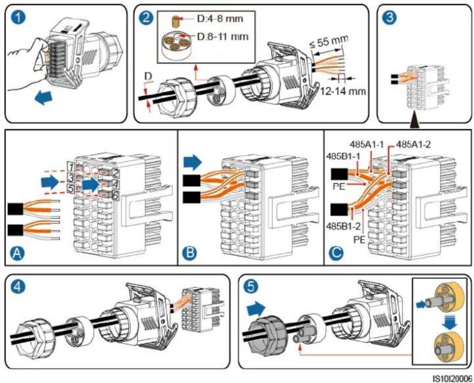
Step 2 Connect the signal cable connector to the COM port.
Figure 5-21 Securing the signal cable connector
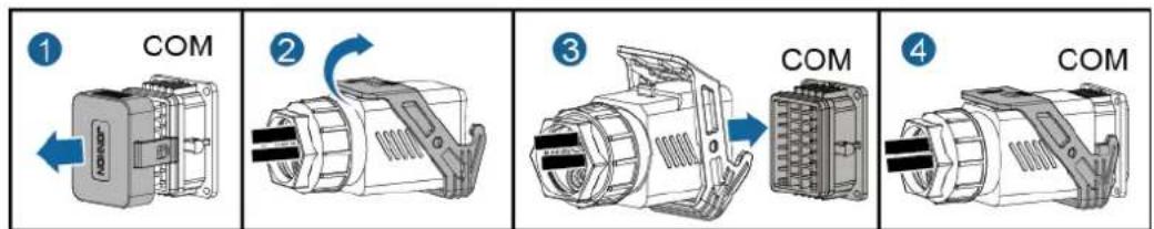
IS10I20007
----End
5.6.2 Connecting the RS485 Communications Cable (Smart Power Sensor)
Cable Connection
The following figure shows the cable connections between the inverter and the Smart Power Sensor.
Figure 5-22 Cable connection
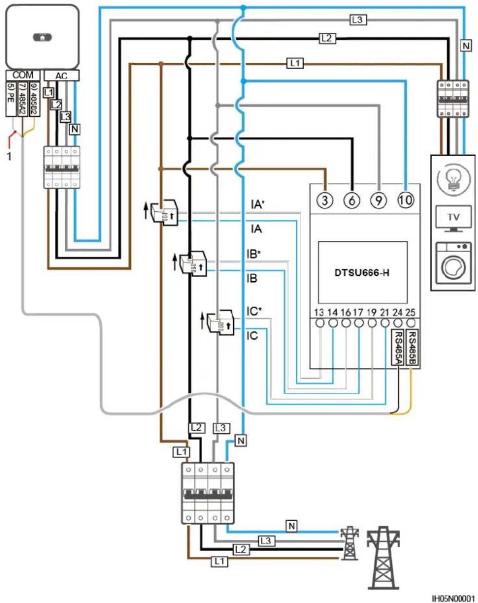
(1) Shielding layer of the signal cable
Procedure
Step 1 Connect the signal cable to the signal cable connector.
Figure 5-23 Installing the cable
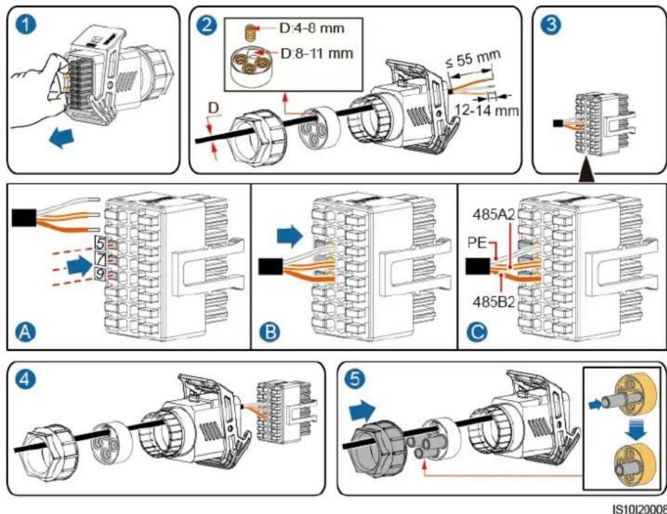
Step 2 Connect the signal cable to the COM port.
Figure 5-24 Securing the signal cable connector
IS10I20007
----End
5.6.3 Connecting the Power Grid Scheduling Signal Cable
Cable Connection
The following figure shows the cable connections between the inverter and the Ripple Control Device.
Figure 5-25 Cable connection
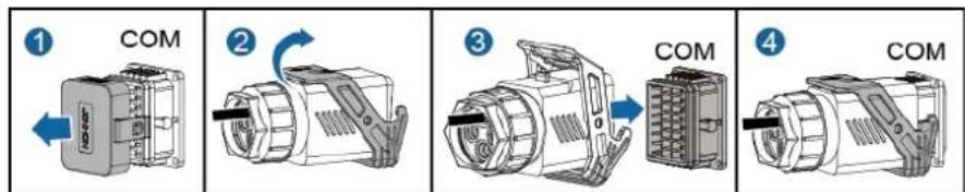
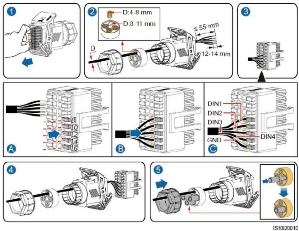
Procedure
Step 1 Connect the signal cable to the signal cable connector.
Figure 5-26 Installing the cable
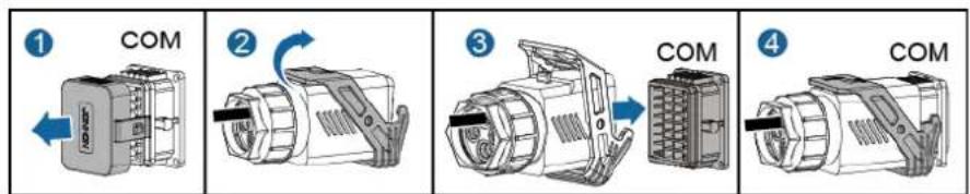
Step 2 Connect the signal cable to the COM port.
Figure 5-27 Securing the signal cable connector
IS10I20007
----End
6 Commissioning
6.1 Check Before Power-On
Table 6-1 Installation checklist
| No. | Check Item | Acceptance Criteria |
| 1 | SUN2000 installation | The SUN2000 is installed correctly, securely, and reliably. |
| 2 | Smart Dongle | The Smart Dongle is installed correctly and securely. |
| 3 | Cable layout | Cables are routed properly as required by the customer. |
| 4 | Cable tie | Cable ties are secured evenly and no burr exists. |
| 5 | Grounding | The ground cable is connected correctly, securely, and reliably. |
| 6 | Turn off the switches | The DC SWITCH and all the switches connected to the SUN2000 are set to OFF. |
| 7 | Cable connections | The AC output power cable and DC input power cable are connected correctly, securely, and reliably. |
| 8 | Unused terminals and ports | Unused terminals and ports are locked by watertight caps. |
| 9 | Installation environment | The installation space is proper, and the installation environment is clean and tidy, without foreign matter. |
6.2 Powering On the System
Precautions
NOTICE
Before turning on the AC switch between the SUN2000 and the power grid, use a multimeter set to the AC position to check that the AC voltage is within the specified range.
Procedure
Step 1 Turn on the AC switch between the SUN2000 and the power grid.
NOTICE
If the DC is on and the AC is off, the SUN2000 reports a Grid Failure alarm. The SUN2000 starts normally only after the fault is automatically rectified.
Step 2 If there is a DC switch between the PV string and the inverter, turn on the DC switch.
Step 3 Set the DC SWITCH at the bottom of the SUN2000 to the ON position.
Step 4 Wait for about 1 minute, and then observe the LED indicators of the inverter to check the running status.
Table 6-2 LED indicator description
| Category | Status | Meaning | |
| Running indicationLED1 LED2 | LED1 | LED2 | N/A |
| Steady green | Steady green | The SUN2000 is operating in grid-tied mode. | |
| Blinking green at long intervals (on for 1s and then off for 1s) | Off | The DC is on and the AC is off. | |
| Blinking green at long intervals (on for 1s and then off for 1s) | Blinking green at long intervals (on for 1s and then off for 1s) | The DC is on, the AC is on, and the SUN2000 is not exporting power to the power grid. | |
| Off | Off | The DC is off.^a | |
| Blinking red at short intervals (on for 0.2s and then off for 0.2s) | N/A | DC environmental alarm | |
| N/A | Blinking red at short intervals (on for 0.2s and then off for 0.2s) | AC environmental alarm | |
| Steady red | Steady red | Fault | |
| Communication indication[IMAGE] | LED3 | N/A | |
| Blinking green at short intervals (on for 0.2s and then off for 0.2s) | Communication is in progress.(When a mobile phone is connected to the SUN2000, the indicator first indicates that the phone is connected to the SUN2000): blinks green at long intervals.) | ||
| Blinking green at long intervals (on for 1s and then off for 1s) | The mobile phone is connected to the SUN2000. | ||
| Off | There is no communication. | ||
| Note a: The AC may be on. Check whether the external AC switch is OFF. | |||
----End
6.3 Commissioning
6.3.1 Scenario 1: Single inverter + Smart Dongle
Downloading the App
Search for "FusionSolar" from the following app stores or scan the corresponding QR code, download the installation package, and install the FusionSolar app by following the instructions.
• Google Play (Android)
- App Store (iOS)
Figure 6-1 FusionSolar QR code

NOTE
The screenshots shown in the document are from FusionSolar 2.3.0. Data in the screenshots is for reference only. The actual screens prevail.
In Britain, only the FusionHome app can be used for commissioning. This document uses the FusionSolar app as an example to describe the commissioning method. For the FusionHome app, perform operations as required.
Search for "FusionHome" from the following app stores or scan the corresponding QR code, download the installation package, and install the FusionHome app by following the instructions.
• Google Play (Android)
- App Store (iOS)
Figure 6-2 FusionHome QR code

NOTE
• The initial password for connecting the inverter WiFi is Changeme
- Log in to the FusionHome app as installer. The initial password is 00000a.
- Use the initial password upon first power-on and change it immediately after login. To ensure account security, change the password periodically and keep the new password in mind. Not changing the initial password may cause password disclosure. A password left unchanged for a long period of time may be stolen or cracked. If a password is lost, devices cannot be accessed. In these cases, the user is liable for any loss caused to the PV plant.
(Optional) Installer Account Registration
Creating the first installer account will generate a domain named after the company.

NOTE
If you have an installer account, skip this step.
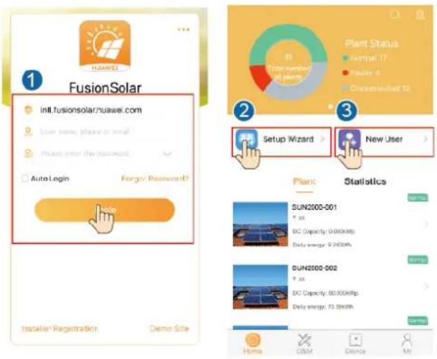
Figure 6-3 Creating the first installer account
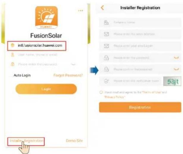
NOTICE
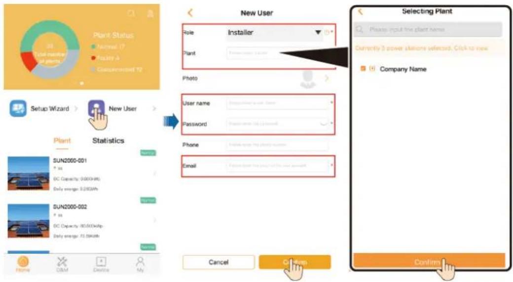
To create multiple installer accounts for the same company, log in to the FusionSolar app and tap New User.
Figure 6-4 Creating multiple installer accounts for the same company
Creating a PV Plant and an Account for User
Figure 6-5 Creating a PV Plant and an Account for User

NOTE
For details, see the FusionSolar App Quick Guide.
You can scan the QR code to obtain it.

6.3.2 Scenario 2: Multiple Inverters + SmartLogger1000A
See the Distributed PV Plants Connecting to Huawei Hosting Cloud Quick Guide (Distributed Inverters + SmartLogger1000A + RS485 Networking).
You can scan the QR code to obtain it.

6.3.3 Other Scenarios
- Access Inverter commissioning.
Figure 6-6 Method 1: before login
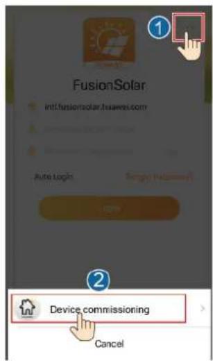
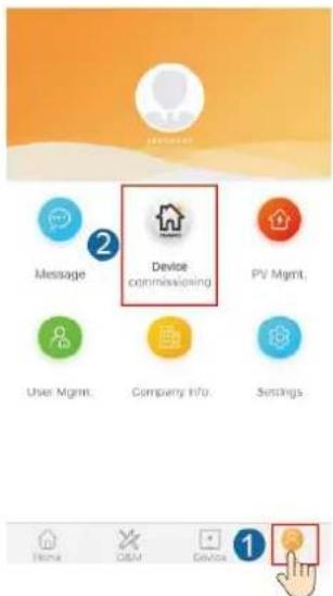
Figure 6-7 Method 2: after login
2. Connect to the inverter WiFi. Log in as installer, and perform Quick settings.
NOTE
- When the inverter is directly connected to the mobile phone using the built-in antenna, the distance between the inverter and mobile phone must be less than 5 m without obstructions in between to ensure the communication quality between the FusionSolar app and inverter. The distance is for reference only and may vary depending on mobile phones and whether there are obstructions between the inverter and the mobile phone.
- When connecting the SUN2000L to the FusionSolar app over a router, ensure that the mobile phone and inverter are in the WiFi coverage of the router and the SUN2000L is connected to the router.
- The router supports WiFi (IEEE 802.11 b/g/n, 2.4 GHz) and the WiFi signal reaches the inverter.
- The WPA, WPA2, or WPA/WPA2 encryption mode is recommended for routers. Enterprise-level encryption is not supported (for example, public hotspots requiring authentication such as airport WiFi). WEP and WPA TKIP are not recommended because these two encryption modes have serious security defects. If the inverter cannot be connected using WEP, log in to the router and change the encryption mode to WPA2 or WPA/WPA2.
Figure 6-8 Quick settings

NOTE
• The initial password for connecting the inverter WiFi is Changeme
• The initial password of the installer is 00000a
- Use the initial password upon first power-on and change it immediately after login. To ensure account security, change the password periodically and keep the new password in mind. Not changing the initial password may cause password disclosure. A password left unchanged for a long period of time may be stolen or cracked. If a password is lost, devices cannot be accessed. In these cases, the user is liable for any loss caused to the PV plant.
• To set more parameters, tap Parameter configuration.
- (Optional) When multiple inverters are connected to a third-party data collector, set RS485 parameters.
Figure 6-9 RS485 Settings
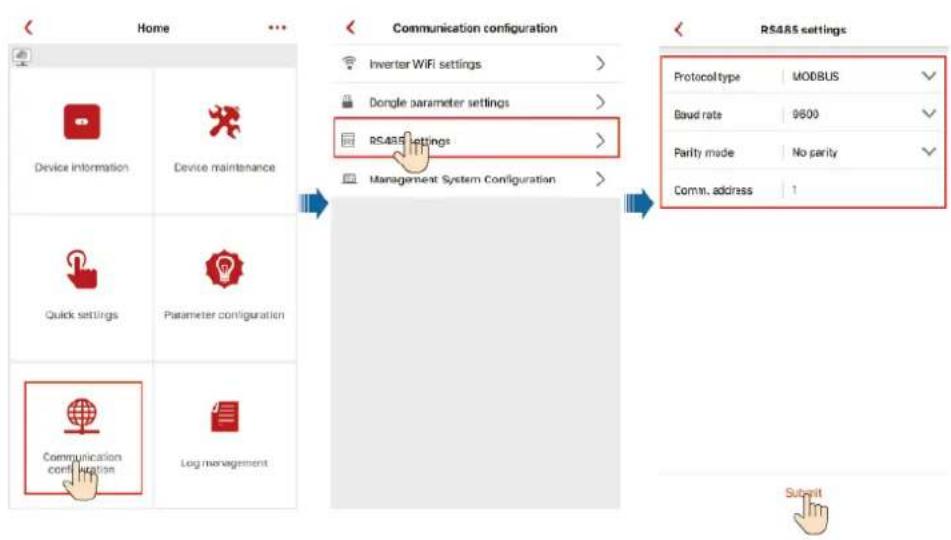

NOTE
The RS485 addresses of different inverters must be different.
6.4 Powering Off the System
Precautions
WARNING
After the SUN2000 is powered off, the remaining electricity and heat may still cause electric shocks or body burns. Therefore, put on protective gloves and operate the SUN2000 five minutes after the power-off.
Procedure
Step 1 Send a shutdown command from the app.
Step 2 Turn off the AC switch between the SUN2000 and the power grid.
Step 3 Set the DC SWITCH at the bottom of the SUN2000 to the OFF position.
Step 4 Turn off the DC switch between the PV string and the SUN2000 if there is one.
----End
7 Maintenance
7.1 Routine Maintenance
To ensure that the SUN2000 can operate properly for a long term, you are advised to perform routine maintenance on it as described in this chapter.
CAUTION
Before cleaning the system, connecting cables, and maintaining the grounding reliability, power off the system.
Table 7-1 Maintenance list
| Check Detail | Check Method | Maintenance Interval |
| System cleanliness | Check the heat sink for foreign matter or the overall health of the SUN2000. | Annual or every time an abnormality is detected |
| System running status | Check the SUN2000 for damage or deformation. | Annual |
| Electrical connections | Cables are securely connected.Cables are intact, in particular, the parts touching the metallic surface are not scratched. | The first inspection is 6 months after the initial commissioning. From then on, the interval can be 6 to 12 months. |
| Grounding reliability | Check whether the ground terminal and ground cable are securely connected. | Annual |
| Sealing | Check whether all terminals and ports are properly sealed. | Annual |
7.2 Troubleshooting
Alarm severities are defined as follows:
- Major: The inverter is faulty. As a result, the output power decreases or the grid-tied power generation is stopped.
- Minor: Some components are faulty without affecting the grid-tied power generation.
- Warning: The inverter works properly. The output power decreases or some authorization functions fail due to external factors.
Table 7-2 Common alarms and troubleshooting measures
| Alarm ID | Alarm Name | Alarm Severity | Possible Cause | Troubleshooting Suggestion |
| 2001 | High String Input Voltage | Major | Excessive PV modules are connected in series in the PV array. Therefore, the open-circuit voltage exceeds the maximum input voltage of the SUN2000.Cause ID 1 = PV1 and PV2Cause ID 2 = PV3 and PV4 | Check the number of PV modules connected in series in the PV string, and ensure that the PV string open-circuit voltage is no greater than the maximum operating voltage of the SUN2000. After you correctly configure the PV array, the inverter alarm disappears automatically. |
| 2002 | DC Arc Fault | Major | The PV string power cable arcs or is in poor contact.Cause ID 1 = PV1 and PV2Cause ID 2 = PV3 and PV4 | Check whether the string cables arc or arc in poor contact. |
| 2011 | String Reversed | Major | The PV string is reversely connected.Cause ID 1 = PV1Cause ID 2 = PV2Cause ID 3 = PV3Cause ID 4 = PV4 | Check whether the PV string is reversely connected to the SUN2000. If so, wait until the solar irradiance declines at night and the PV string current drops to below 0.5 A. Then, set the DC SWITCH to the OFF position, and correct the string polarity. |
| 2012 | String Current Backfeed | Warning | Only a few PV modules are connected in series in the PV string. Therefore, the end voltage is lower than that of other PV strings.Cause ID 1 = PV1Cause ID 2 = PV2Cause ID 3 = PV3Cause ID 4 = PV4 | 1. Check whether the number of PV modules connected in series to this PV string is less than the number of PV modules connected in series to the other PV strings connected in parallel with this PV string. If yes, wait until the PV string current drops below 0.5 A, set DC SWITCH to OFF, and adjust the number of PV modules in the PV string.2. Check whether the PV string is shaded.3. Check whether the open-circuit voltage of the PV string is normal. |
| 2031 | Power grid phase wire short-circuit to PE | Major | Cause ID = 1The impedance of the output phase wire is low or short-circuited to PE. | Check the impedance of the output phase wire to PE, locate the position with lower impedance and restore that. |
| 2032 | Grid Failure | Major | Cause ID = 1• The power grid experiences an outage.• The AC circuit is disconnected or the AC switch is off. | 1. Check the AC voltage.2. Check whether the AC circuit is disconnected or whether the AC switch is off. |
| 2033 | Grid Undervoltage | Major | Cause ID = 1The power grid voltage is below the lower threshold or the undervoltage duration exceeds the value specified by LVRT. | 1. If the alarm occurs occasionally, the power grid may be abnormal temporarily. The SUN2000 automatically recovers after detecting that the power grid becomes normal.2. If the alarm occurs frequently, check whether the grid voltage is within the acceptable range. If no, contact the local power operator. If yes, log in to the mobile phone app, SmartLogger, or NMS to modify the grid undervoltage protection threshold with the consent of the local power operator.3. If the fault persists for a long time, check the connection between the AC switch and the output power cable. |
| 2034 | Grid Overvoltage | Major | Cause ID = 1The power grid voltage is beyond the upper threshold or the overvoltage duration exceeds the value specified by HVRT. | 1. If the alarm occurs occasionally, the power grid may be abnormal temporarily. The SUN2000 automatically recovers after detecting that the power grid becomes normal.2. If the alarm occurs frequently, check whether the grid voltage is within the acceptable range. If no, contact the local power operator. If yes, log in to the mobile phone app, SmartLogger, or NMS to modify the grid overvoltage protection threshold with the consent of the local power operator.3. Check whether the peak voltage of the power grid is too high. If the fault persists and cannot be rectified for a long time, contact the power operator. |
| 2035 | Unbalanced Grid Voltage | Major | Cause ID = 1The difference between grid phase voltages exceeds the upper threshold. | 1. If the alarm occurs occasionally, the power grid may be abnormal temporarily. The SUN2000 automatically recovers after detecting that the power grid becomes normal.2. If the alarm occurs frequently, check whether the grid voltage is within the acceptable range. If no, contact the local power operator.3. If the fault persists for a long time, check the connection between the AC switch and the output power cable. |
| 2036 | Grid Overfrequency | Major | Cause ID = 1Power grid exception: The actual power grid frequency is higher than the standard requirement for the local power grid. | 1. If the alarm occurs occasionally, the power grid may be abnormal temporarily. The SUN2000 automatically recovers after detecting that the power grid becomes normal.2. If the alarm occurs frequently, check whether the grid frequency is within the acceptable range. If no, contact the local power operator. If yes, log in to the mobile phone app, SmartLogger, or NMS to modify the grid overfrequency protection threshold with the consent of the local power operator. |
| 2037 | Grid Underfrequency | Major | Cause ID = 1Power grid exception: The actual power grid frequency is lower than the standard requirement for the local power grid. | 1. If the alarm occurs occasionally, the power grid may be abnormal temporarily. The SUN2000 automatically recovers after detecting that the power grid becomes normal.2. If the alarm occurs frequently, check whether the grid frequency is within the acceptable range. If no, contact the local power operator. If yes, log in to the mobile phone app, SmartLogger, or NMS to modify the grid underfrequency protection threshold with the consent of the local power operator. |
| 2038 | Unstable Grid Frequency | Major | Cause ID = 1Power grid exception: The actual grid frequency change rate does not comply with the local power grid standard. | 1. If the alarm occurs occasionally, the power grid may be abnormal temporarily. The SUN2000 automatically recovers after detecting that the power grid becomes normal.2. If the alarm occurs frequently, check whether the power grid frequency is within the acceptable range. If not, contact the local power operator. |
| 2039 | Output Overcurrent | Major | Cause ID = 1The power grid voltage drops dramatically or the power grid is short-circuited. As a result, the SUN2000 transient output current exceeds the upper threshold and therefore the protection is triggered. | 1. The SUN2000 detects its external working conditions in real time. After the fault is rectified, it automatically recovers.2. If the alarm occurs frequently and affects the power production of the PV plant, check whether the output is short-circuited. If the fault persists, contact your dealer or Huawei technical support. |
| 2040 | Output DC Component Overhigh | Major | Cause ID = 1The DC component of the SUN2000 output current exceeds the specified upper threshold. | 1. The SUN2000 detects its external working conditions in real time. After the fault is rectified, it automatically recovers.2. If the alarm occurs frequently, contact your dealer or Huawei technical support. |
| 2051 | Abnormal Residual Current | Major | Cause ID = 1The insulation impedance of the input side to PE decreases when the SUN2000 is operating. | 1. If the alarm occurs occasionally, the external power cable may be abnormal temporarily. The SUN2000 automatically recovers after the fault is rectified.2. If the alarm occurs frequently or persists, check whether the impedance of the PV string to ground is excessively low. |
| 2061 | Abnormal Grounding | Major | Cause ID = 1The N cable or ground cable is not connected.When a PV array is grounded, the inverter output is not connected to an isolation transformer. | Power off the inverter and check the following items:Check whether the PE cable of the SUN2000 is connected properly.If the inverter is connected to the TN power grid, check whether the N cable is properly connected and whether the voltage of the N cable to ground is normal.Check whether the output is connected to an isolation transformer. If yes, setGrounding inspection toDisablethrough the mobile phone app, SmartLogger, or NMS. |
| 2062 | Low Insulation Resistance | Major | Cause ID = 1PV arrays are short-circuited with PE.The ambient air of the PV array is damp and the insulation between the PV array and the ground is poor. | Check the output resistance of the PV array to ground. If there is a short circuit or lack of insulation, rectify it.Check that the PE cable of the SUN2000 is correctly connected.If you are sure that the impedance is less than the default value in a cloudy or rainy environment, log in to the mobile phone app, SmartLogger, or NMS and reset the insulation impedance protection threshold. |
| 2063 | Overtemperature | Minor | Cause ID = 1The SUN2000 is installed in a place with poor ventilation.The ambient temperature is too high.The SUN2000 is not working properly. | Check the ventilation and ambient temperature of the SUN2000 installation position.If the ventilation is poor or the ambient temperature exceeds the upper threshold, improve the ventilation and heat dissipation.If the ventilation and ambient temperature both meet requirements, contact your dealer or Huawei technical support. |
| 2064 | Device Fault | Major | Cause ID = 1–12An unrecoverable fault has occurred on a circuit inside the SUN2000. | Turn off the AC output switch and DC input switch, and then turn them on after 5 minutes. If the fault persists, contact your dealer or Huawei technical support.Note: If the cause ID is ID 1, perform the preceding operation when the PV string current is less than 1 A. |
| 2065 | Upgrade Failed or Software Version Unmatch | Minor | Cause ID = 1, 2 and 4The upgrade does not end normally.NOTEUpgrade the inverter again if it is stuck in initialization state without generating any alarms and cannot be restored to the normal state during the upgrade when the PV inputs are disconnected and reconnected next time. | Perform the upgrade again.If the upgrade fails several times, contact your dealer or Huawei technical support. |
| 2066 | License Expired | Minor | Cause ID = 1The privilege certificate has entered the grace period.The privilege feature will be invalid soon. | Apply for a new certificate.Load the new certificate. |
| 61440 | Monitoring Unit Faulty | Minor | Cause ID = 1The flash memory is insufficient.The flash memory has bad sectors. | Turn off the AC output switch and then the DC input switch. After 5 minutes, turn on the AC output switch and then the DC input switch. If the fault persists, replace the board, If the upgrade fails several times, contact your dealer or Huawei technical support. |
| 2067 | Faulty Power Collector | Major | Cause ID = 1The power meter communication is interrupted. | Check that the power meter settings are based on the actual model.Check that the communications parameters for the power meter are the same as the SUN2000 RS485 parameter settings.Check that the power meter is powered on, and the RS485 cable is connected correctly. |
| 2072 | Transient AC Overvoltage | Major | Cause ID = 1The inverter detects that the phase voltage exceeds the transient AC overvoltage protection threshold. | Check whether the grid connection voltage exceeds the upper threshold. If yes, contact the local power operator.If you have confirmed that the grid-tied voltage exceeds the upper threshold and have obtained the consent of the local power operator, modify the overvoltage protection threshold through the mobile phone app, SmartLogger, or NMS.Check whether the peak power grid voltage exceeds the upper threshold. |

NOTE
Contact your dealer or Huawei technical support if the measures listed in the Troubleshooting Suggestion column have been taken but the fault persists.
8
Handling the Inverter
8.1 Removing the SUN2000
NOTICE
Before removing the SUN2000, disconnect both the AC and DC power supplies. After powering off the SUN2000, wait at least 5 minutes before performing operations on the SUN2000.
Perform the following operations to remove the SUN2000:
- Disconnect all cables from the SUN2000, including RS485 communications cables, DC input power cables, AC output power cables, and PGND cables.
- Remove the SUN2000 from the mounting bracket.
- Remove the mounting bracket.
8.2 Packing the SUN2000
- If the original packing materials are available, put the SUN2000 inside them and then seal them by using adhesive tape.
- If the original packing materials are not available, put the SUN2000 inside a suitable cardboard box and seal it properly.
8.3 Disposing of the SUN2000
If the SUN2000 service life expires, dispose of it according to the local disposal rules for electrical equipment waste.
9
Technical Data
NOTICE
The SUN2000-8KTL-M0 and SUN2000-10KTL-M0 inverters are applicable only to Australia.
Efficiency
| Technical Specifications | SUN2000-8KTL-M0 | SUN2000-10KTL-M0 | SUN2000-12KTL-M0 | SUN2000-15KTL-M0 | SUN2000-17KTL-M0 | SUN2000-20KTL-M0 |
| Maximum efficiency | 98.5% | 98.5% | 98.5% | 98.65% | 98.65% | 98.65% |
| European efficiency | 98.0% | 98.0% | 98.0% | 98.3% | 98.3% | 98.3% |
Input
| Technical Specifications | SUN2000-8KTL-M0 | SUN2000-10KTL-M0 | SUN2000-12KTL-M0 | SUN2000-15KTL-M0 | SUN2000-17KTL-M0 | SUN2000-20KTL-M0 |
| Maximum input voltage^a | 1080 V | |||||
| Maximum input current (per MPPT) | 22 A | |||||
| Maximum short-circuit current (per MPPT) | 30 A | |||||
| Maximum inverter backfeed current to the PV array | 0 A | |||||
| Minimum startup voltage | 200 V | |||||
| Operating voltage rangeb | 160–950 V | |||||
| Full-load MPPT voltage range | 320–850 V | 320–850 V | 380–850 V | 380–850 V | 400–850 V | 480–850 V |
| Rated input voltage | 600 V | |||||
| Number of input routes | 4 | |||||
| Number of MPP trackers | 2 | |||||
| Note a: The maximum input voltage is the upper threshold of the DC voltage. If the input voltage exceeds the threshold, the solar inverter may be damaged.Note b: If the input voltage is beyond the operating voltage range, the solar inverter cannot work properly. | ||||||
Output
| Technical Specifications | SUN2000-8KTL-M0 | SUN2000-10KTL-M0 | SUN2000-12KTL-M0 | SUN2000-15KTL-M0 | SUN2000-17KTL-M0 | SUN2000-20KTL-M0 |
| Rated active power | 8000 W | 10000 W | 12000 W | 15000 W | 17000 W | 20000 W |
| Maximum apparent power | 8800 VA | 11000 VA | 13200 VA | 16500 VA | 18700 VA | 22000 VA |
| Maximum active power (cosφ = 1) | 8800 W | 11000 W | 13200 W | 16500 W | 18700 W | 22000 W |
| Rated output voltage | 220/380 V, 230/400 V, 3W+(N)+PE | |||||
| Rated output current | 12.8 A (380 V)/11.6 A (400 V) | 15.9 A (380 V)/14.5 A (400 V) | 18.2 A (380 V)/17.3 A (400 V) | 22.8 A (380 V)/21.7 A (400 V) | 25.8 A (380 V)/24.6 A (400 V) | 30.4 A (380 V)/28.9 A (400 V) |
| Maximum output current | 13.4 A | 17 A | 20 A | 25.2 A | 28.5 A | 33.5 A |
| Adapted power grid frequency | 50/60 Hz | |||||
| Power factor | 0.8 leading... 0.8 lagging | |||||
| Maximum total harmonic distortion (rated power) | < 3% | |||||
| Inrush current | 153 A (peak current, duration < 33 μs) | |||||
| Maximum output fault current | 237 A (peak current, duration < 1ms) | |||||
| Maximum output overcurrent protection | 13.45 A | |||||
Protection and Feature
| Technical Specifications | SUN2000-8KTL-M0 | SUN2000-10KTL-M0 | SUN2000-12KTL-M0 | SUN2000-15KTL-M0 | SUN2000-17KTL-M0 | SUN2000-20KTL-M0 |
| AFCI | Yes | |||||
| Input DC switch | Yes | |||||
| Anti-islanding protection | Yes | |||||
| Output overcurrent protection | Yes | |||||
| Output short-circuit protection | Yes | |||||
| Output overvoltage protection | Yes | |||||
| Input reverse connection protection | Yes | |||||
| PV string fault detection | Yes | |||||
| DC surge protection | Yes | |||||
| AC surge protection | Yes | |||||
| Insulation resistance detection | Yes | |||||
| Residual current monitoring unit (RCMU) | Yes | |||||
Display and Communication
| Technical Specifications | SUN2000-8KTL-M0 | SUN2000-10KTL-M0 | SUN2000-12KTL-M0 | SUN2000-15KTL-M0 | SUN2000-17KTL-M0 | SUN2000-20KTL-M0 |
| Display | LED indicators; WLAN+app | |||||
| RS485 | Yes | |||||
| Communicationsexpansionmodule | (Optional) WLAN/4G | |||||
| Remote drycontact scheduling | Yes | |||||
Common Parameters
| Technical Specifications | SUN2000-8KTL-M0 | SUN2000-10KTL-M0 | SUN2000-12KTL-M0 | SUN2000-15KTL-M0 | SUN2000-17KTL-M0 | SUN2000-20KTL-M0 |
| Dimensions (W x H x D) | 525mm×470mm×262mm | |||||
| Net weight | 25 kg | |||||
| Operating temperature | -25°C to +60°C (derated at +45°C or higher) | |||||
| Cooling mode | Natural convection | |||||
| Highest operating altitude | 0–4000 m (derated above 2000 m) | |||||
| Relative humidity | 0%–100% RH | |||||
| Input terminal | Amphenol Helios H4 | |||||
| Output terminal | Waterproof quick-connect terminal | |||||
| IP rating | IP65 | |||||
| Topology | No transformer | |||||
A
Grid Codes

NOTE
The grid codes are subject to change. The listed codes are for your reference only.
Table A-1 Grid Codes
| No. | Grid Codes | Description |
| 1 | VDE-AR-N-4105 | Germany low-voltage power grid |
| 2 | UTE C 15-712-1 (A) | France mainland low-voltage power grid |
| 3 | UTE C 15-712-1 (B) | France island power grid (230 V 50 Hz) |
| 4 | UTE C 15-712-1 (C) | France island power grid (230 V 60 Hz) |
| 5 | VDE 0126-1-1-BU | Bulgaria low-voltage power grid |
| 6 | VDE 0126-1-1-GR (A) | Greece mainland low-voltage power grid |
| 7 | VDE 0126-1-1-GR (B) | Greece island low-voltage power grid |
| 8 | BDEW-MV | Germany medium-voltage power grid |
| 9 | G59-England | England 230 V power grid (I > 16 A) |
| 10 | G59-Scotland | Scotland 240 V power grid (I > 16 A) |
| 11 | G83-England | England 230 V power grid (I < 16 A) |
| 12 | G83-Scotland | England 240 V power grid (I < 16 A) |
| 13 | CEI0-21 | Italy low-voltage power grid |
| 14 | EN50438-CZ | Czech Republic low-voltage power grid |
| 15 | RD1699/661 | Spain low-voltage power grid |
| 16 | EN50438-NL | Netherlands low-voltage power grid |
| 17 | C10/11 | Belgium low-voltage power grid |
| 18 | AS4777 | Australia low-voltage power grid |
| 19 | IEC61727 | IEC61727 low-voltage power grid (50 Hz) |
| 20 | User-defined (50 Hz) | Reserved |
| 21 | User-defined (60 Hz) | Reserved |
| 22 | CEI0-16 | Italy low-voltage power grid |
| 23 | TAI-PEA | Thailand low-voltage power grid (PEA) |
| 24 | TAI-MEA | Thailand low-voltage power grid (MEA) |
| 25 | EN50438-TR | Turkey low-voltage power grid |
| 26 | Philippines | Philippines low-voltage power grid |
| 27 | NRS-097-2-1 | South Africa low-voltage power grid |
| 28 | KOREA | South Korea low-voltage power grid |
| 29 | IEC61727-60Hz | IEC61727 low-voltage power grid (60 Hz) |
| 30 | ANRE | Romania low-voltage power grid |
| 31 | EN50438_IE | Ireland low-voltage power grid |
| 32 | PO12.3 | Spain low-voltage power grid |
| 33 | Egypt ETEC | Egypt medium-voltage power grid |
| 34 | CLC/TS50549_IE | Ireland low-voltage power grid |
| 35 | Jordan-Transmission | Jordan low-voltage power grid |
| 36 | NAMIBIA | Namibia low-voltage power grid |
| 37 | ABNT NBR 16149 | Brazil low-voltage power grid |
| 38 | SA_RPPs | South Africa low-voltage power grid |
| 39 | INDIA | India low-voltage power grid |
| 40 | ZAMBIA | Zambia low-voltage power grid |
| 41 | Chile | Chile low-voltage power grid |
| 42 | Malaysian | Malaysia low-voltage power grid |
| 43 | KENYA_ETHIOPIA | Kenya low-voltage power grid and Ethiopia low-voltage power grid |
| 44 | NIGERIA | Nigeria low-voltage power grid |
| 45 | DUBAI | Dubai low-voltage power grid |
| 46 | Northern Ireland | Northern Ireland low-voltage power grid |
| 47 | Cameroon | Cameroon low-voltage power grid |
| 48 | Jordan-Distribution | Jordan power distribution network low-voltage power grid |
| 49 | LEBANON | Lebanon low-voltage power grid |
| 50 | TUNISIA | Tunisia low-voltage power grid |
| 51 | AUSTRALIA-NER | Australia NER standard low-voltage power grid |
| 52 | SAUDI | Saudi Arabia low-voltage power grid |
| 53 | Israel | Israel low-voltage power grid |
| 54 | Chile-PMGD | Chile PMGD low-voltage power grid |
| 55 | VDE-AR-N4120_HV | VDE41200 standard low-voltage power grid |
| 56 | Vietnam | Vietnam low-voltage power grid |
| 57 | TAIPOWER | Taiwan low-voltage power grid |
| 58 | OMAN | Oman low-voltage power grid |
| 59 | KUWAIT | Kuwait low-voltage power grid |
| 60 | BANGLADESH | Bangladesh low-voltage power grid |
| 61 | CHILE_NET_BILLING | Chile Net Billing low-voltage power grid |
| 62 | BAHRAIN | Bahrain low-voltage power grid |
| 63 | Fuel-Engine-Grid | DG hybrid low-voltage power grid (50 Hz) |
| 64 | Fuel-Engine-Grid-60Hz | DG hybrid low-voltage power grid (60 Hz) |
| 65 | ARGENTINA | Argentina low-voltage power grid |
| 66 | Mauritius | Mauritius low-voltage power grid |
| 67 | EN50438-SE | Sweden low-voltage power grid |
| 68 | Austria | Austria |
| 69 | G99-TYPEA-LV | United Kingdom |
| 70 | G99-TYPEB-LV | United Kingdom |
| 71 | G99-TYPEB-HV | United Kingdom |
| 72 | G99-TYPEA-HV | United Kingdom |
B
Setting Dry Contact Scheduling Parameters
Scenario 1: Single inverter + Smart Dongle
Prerequisites
You have logged in to the app as installer. The initial password is 00000a. Use the initial password upon first power-on and change it immediately after login. To ensure account security, change the password periodically and keep the new password in mind. Not changing the initial password may cause password disclosure. A password left unchanged for a long period of time may be stolen or cracked. If a password is lost, devices cannot be accessed. In these cases, the user is liable for any loss caused to the PV plant.
Procedure
Step 1 Set dry contact scheduling parameters.

NOTE
Set Dry contact scheduling to

and set Active power control and Reactive power control.
Figure B-1 Setting dry contact scheduling parameters
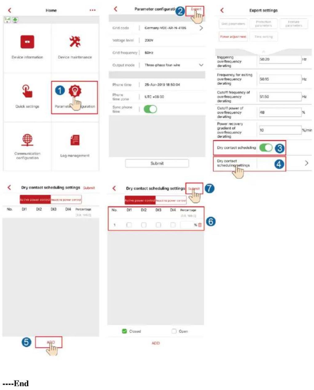
----End
Scenario 2: Multiple Inverters + SmartLogger1000A
See the SmartLogger1000A User Manual.
C Setting Export Limitation Parameters
Scenario 1: Single inverter + Smart Dongle
Prerequisites
You have logged in to the app as installer. The initial password is 00000a. Use the initial password upon first power-on and change it immediately after login. To ensure account security, change the password periodically and keep the new password in mind. Not changing the initial password may cause password disclosure. A password left unchanged for a long period of time may be stolen or cracked. If a password is lost, devices cannot be accessed. In these cases, the user is liable for any loss caused to the PV plant.
Procedure
Step 1 Set export limitation parameters.
Figure C-1 Setting export limitation parameters
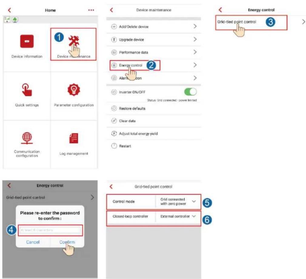
Table C-1 Setting export limitation parameters
| Parameter | Value Range | Description |
| Control mode | Not restrictedGrid connected with zero powerPower-limited grid connected | If this parameter is set to Not restricted, the SUN2000 output power is not limited. The SUN2000 can export its rated power to the power grid.If this parameter is set to Grid connection with zero power and the SUN2000 is connected to a power meter, the output power of the SUN2000 is supplied only to the local load, but not the power grid.If this parameter is set to Power-limited grid connection and the SUN2000 is connected to a Smart power sensor, the SUN2000 supplies power limited based on the setting of Grid-tied Point Power to the power grid. |
| Closed-loop controller | External controllerInverter | Set this parameter to External controller when the SmartLogger1000A is connected.If multiple inverters are cascaded, set this parameter to External controller.If a single inverter is used, set this parameter to Inverter. |
----End
Scenario 2: Multiple Inverters + SmartLogger1000A
See the SmartLogger1000A User Manual.
D
Setting Voltage Rise Suppression Q-U Curve
Scenario 1: Single inverter + Smart Dongle
Prerequisites
You have logged in to the app as installer. The initial password is 00000a. Use the initial password upon first power-on and change it immediately after login. To ensure account security, change the password periodically and keep the new password in mind. Not changing the initial password may cause password disclosure. A password left unchanged for a long period of time may be stolen or cracked. If a password is lost, devices cannot be accessed. In these cases, the user is liable for any loss caused to the PV plant.
Procedure
Step 1 Set voltage rise suppression Q-U curve parameters.
Figure D-1 Setting voltage rise suppression Q-U curveparameters
![Home Device information Device maintenance Quick settings Parameter configuration Communication configuration Log management Parameter configurati Grid code | Germany-VDE-AR-N-4105 Voltage level | 230V Grid frequency | 60Hz Output mode | Three-phase four-wire Phone time | 25-Apr-2019 18:50:04 Phone time zone | UTC +08:00 Sync phone time Submit Expert settings Grid parameters | Protection parameters | Feature parameters Power adjustment | Time setting TCP frame length 1236 Heartbeat period at application layer 30 Min Delay upgrade LVRT HVRT Anti-islanding protection Voltage rise suppression 3 Soft start time after grid failure 600 s Voltage rise suppression P-U curve Voltage rise suppression Q-U curve 4 Voltage rise suppression Q-U curve Voltage rise suppression Q-U curve Characteristic curve points 5 2 + U(V) Q/S [194.0-312.6] [-0.600-6.500] 1 207.0 0.600 2 226.0 0.600 7 Submit ----End](/content/2026/05/766454/images/178b823adfde3e78684fad9834083a9bc9775856a2b84c7739098baba1697d22.jpg)
Scenario 2: Multiple Inverters + SmartLogger1000A
See the SmartLogger1000A User Manual.
E
Starting AFCI Check
Prerequisites
You have logged in to the app as installer. The initial password is 00000a. Use the initial password upon first power-on and change it immediately after login. To ensure account security, change the password periodically and keep the new password in mind. Not changing the initial password may cause password disclosure. A password left unchanged for a long period of time may be stolen or cracked. If a password is lost, devices cannot be accessed. In these cases, the user is liable for any loss caused to the PV plant.
Procedure
Step 1 On the Home screen, choose Device maintenance > Start AFCI check and perform the required operation.
Figure E-1 Start AFCI check
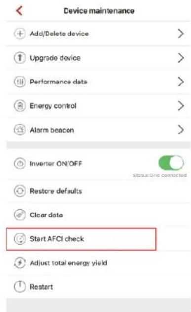
----End
F IPS Test (for Italy CEI0-21 Grid Code only)
Prerequisites
You have logged in to the app as installer. The initial password is 00000a. Use the initial password upon first power-on and change it immediately after login. To ensure account security, change the password periodically and keep the new password in mind. Not changing the initial password may cause password disclosure. A password left unchanged for a long period of time may be stolen or cracked. If a password is lost, devices cannot be accessed. In these cases, the user is liable for any loss caused to the PV plant.
Context
The Italy CEI0-21 grid code requires an IPS test for the SUN2000. During the IPS test process, the SUN2000 consecutively tests the protection thresholds and time for 10-min overvoltage, level 1 overvoltage, level 1 undervoltage, level 1 overfrequency, and level 1 underfrequency. The SUN2000 shuts down after the IPS test starts, and it restarts after the IPS test is successful.
Procedure
Step 1 On the Home screen, choose Device maintenance > IPS test to access the IPS test screen.
Figure F-1 IPS test
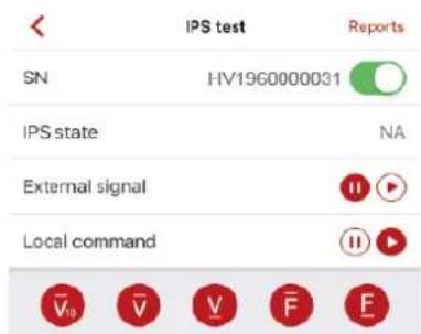
Maximum voltage over 10min(59.S1)
| Trip value setting | NA |
| Trip time setting | NA |
| Measurement value | L1:NA L2:NA L3:NA |
| Measurement trip time | NA |
| Self-check status | NA |
Start
Step 2 Choose to start the S1 or S2 check as required. The default check type is S2. To start the S2 check, you need to set External Signal or Local Command.
Table F-1 IPS test type description
| IPS Test Type | Description | External Signal Setting | Local Command Setting |
| S1 | The level 1 overfrequency protection threshold is 50.5 Hz and the level 1 underfrequency protection threshold is 49.5 Hz. |  |  |
| S2 | The level 1 overfrequency protection threshold is 51.5 Hz and the level 1 underfrequency protection threshold is 47.5 Hz. |  |  |
| S2 (default) | The level 1 overfrequency protection threshold is 51.5 Hz and the level 1 underfrequency protection threshold is 47.5 Hz. |  |  |
| S2 | The level 1 overfrequency protection threshold is 51.5 Hz and the level 1 underfrequency protection threshold is 47.5 Hz. |  |  |
Step 3 Tap Start to start the IPS test. After the IPS test is complete, IPS State is displayed as IPS state success. Tap Reports in the upper right corner of the IPS test screen to view IPS Self-Check Report.
----End
G
DRM Configuration Guide for Standard AS NZS4777.2
If Demand Response Modes are required, then the installer will need to connect the Huawei SmartLogger1000A. Refer to the Huawei document SmartLogger1000A User Manual for Standard AS NZS4777.2 of how to connect the DRED and how to configure the inverter and Smart Logger for use with the DRED.
H
Acronyms and Abbreviations
A
ACDU alternating current distribution unit
AFCI arc-fault circuit interrupter
L
LED light emitting diode
M
MPP maximum power point
MPPT maximum power point tracking
P
PV photovoltaic
R
RCD residual current device
W
WEEE waste electrical and electronic equipment
- User Manual
- Trademarks and Permissions
- Notice
- Huawei Technologies Co., Ltd.
- About This Document
- Purpose
- NOTE
- Intended Audience
- Symbol Conventions
- Change History
- Issue 03 (2019-07-19)
- Issue 02 (2019-06-30)
- Issue 01 (2019-05-08)
- Contents
- About This Document...... ii
- Safety Precautions....1
- Overview....4
- Storage....14
- Installation....15
- Electrical Connections....29
- Safety Precautions
- Safety
- Disclaimer
- Personnel Requirements
- Protecting Labels
- Installation
- DANGER
- Grounding
- Electrical Connections
- Operation
- Commissioning
- Maintenance and Replacement
- Overview
- Product Introduction
- Function
- Models
- Network Application
- Supported Power Grids
- Appearance
- Label Description
- Enclosure Labels
- Product Nameplate
- Working Principles
- Circuit Diagram
- Working Modes
- Storage
- Installation
- Checking Before Installation
- Outer Packing Materials
- Package Contents
- Tools
- Determining the Installation Position
- Environment Requirements
- Basic Requirements
- Mounting Structure Requirements
- Space Requirements
- Installation Angle Requirements
- Installation Space Requirements
- Moving an Inverter
- Procedure
- CAUTION
- Installing the Mounting Bracket
- Installation Precautions
- Wall-mounted Installation
- Support-mounted Installation
- Prerequisites
- Electrical Connections
- Precautions
- WARNING
- Preparing for Installation
- Connecting the PE cable
- Additional Information
- Connecting the AC Output Power Cable
- Disconnection
- Connecting the DC input power cable
- Terminal Description
- Locator
- Removing a DC connector
- (Optional) Installing the Smart Dongle
- (Optional) Installing the Signal Cable
- Communication Networking
- Connecting the RS485 Communications Cable (Inverter Cascading)
- Connecting the RS485 Communications Cable (Smart Power Sensor)
- Cable Connection
- Connecting the Power Grid Scheduling Signal Cable
- Commissioning
- Check Before Power-On
- Powering On the System
- Commissioning
- Scenario 1: Single inverter + Smart Dongle
- Downloading the App
- (Optional) Installer Account Registration
- Creating a PV Plant and an Account for User
- Scenario 2: Multiple Inverters + SmartLogger1000A
- Other Scenarios
- Connect to the inverter WiFi. Log in as installer, and perform Quick settings.
- Powering Off the System
- Maintenance
- Routine Maintenance
- Troubleshooting
- 8
- Handling the Inverter
- Removing the SUN2000
- Packing the SUN2000
- Disposing of the SUN2000
- 9
- Technical Data
- A
- Grid Codes
- B
- Setting Dry Contact Scheduling Parameters
- Scenario 1: Single inverter + Smart Dongle
- Scenario 2: Multiple Inverters + SmartLogger1000A
- C Setting Export Limitation Parameters
- D
- Setting Voltage Rise Suppression Q-U Curve
- E
- Starting AFCI Check
- F IPS Test (for Italy CEI0-21 Grid Code only)
- Context
- G
- DRM Configuration Guide for Standard AS NZS4777.2
- H
- Acronyms and Abbreviations
Brand : HUAWEI
Model : SUN2000MA-20KTL-M0
Category : Solar panel