
DY GPS - Gps ABB - Free user manual and instructions
Find the device manual for free DY GPS ABB in PDF.


| Product Type | GPS module for external use |
| Model | DY GPS |
| Brand | ABB |
| Dimensions (W x H x D) | 52 x 79 x 20 mm |
| Power Supply | 12V DC (-20% +20%) |
| Current Consumption | 30 mA max (during GPS reception) |
| Protection Degree | IP54 |
| Operating Temperature | 0°C to +50°C |
| Storage Temperature | -25°C to +70°C |
| Operating Humidity | 20% to 90% non-condensing |
| Cable Length | 100 m |
| Cable Section (flexible) | 0.75 to 1.5 mm² |
| Sheathed Cable Max Diameter | 3 mm |
| Installation | Wall or pole mounting (adapter included) |
| Key Functions | Force data sending to connected devices |
| LED Indicators | Red, green, orange for status (see manual) |
| Data Output | Sends time, date, latitude, longitude every 30 minutes to I/O extension port |
| Satellite Acquisition | Every ~30 seconds |
| Overvoltage Category | III |
| Pollution Degree | 2 |
| Compliance Standards | EN 60950-1; ETSI EN 301 489-1, -3; ETSI EN 300 440-1, -2 |
| Safety Warnings | Install by qualified person; disconnect power before terminals; do not use if damaged |
Frequently Asked Questions - DY GPS ABB
User questions about DY GPS ABB
0 question about this device. Answer the ones you know or ask your own.
Ask a new question about this device
Download the instructions for your Gps in PDF format for free! Find your manual DY GPS - ABB and take your electronic device back in hand. On this page are published all the documents necessary for the use of your device. DY GPS by ABB.
USER MANUAL DY GPS ABB
https://new.abb.com/low-voltage
© Copyright 2019 ABB S.P.A. All rights reserved.
We reserve the right to make technical changes or modify
the contents of this document without prior notice.
DY GPS
Installation Manual
2
DIMENSIONS (mm)
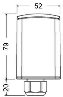

3
CONNECTION DIAGRAMS
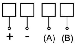
12 V== I/O extension port
4
DEVICE STATUS
- When you power on the led emits two red flashes as follows:
| OFF | ON | OFF | ON | OFF |
| ... | 1 s | 1 s | 1 s | ... |
After the power on sequence, the DY GPS:
- acquires data of time, date, latitude, longitude and number of satellites received about every 30 seconds
- sends data of time, date, latitude, longitude to the I/O extension port (and to the connected devices) every 30 minutes
The flashing of the green led indicates the number of the received satellites (the higher the number of satellites received, the better the reception of the information):
| Number of satellites | Green led sequence | ||
| ON | OFF | REPETITIONS | |
| 0 - 2 | 500 ms | 500 ms | continuous |
| 3 – 5 | 100 ms | 300 ms | 3 every 5 seconds |
| 6 – 8 100 ms | 300 ms | 6 every 5 seconds | |
| 9 – 12 100 ms | 300 ms | 9 every 5 seconds | |
- Sending data to the I/O extension port (and to the connected devices) is signaled by the red flashing of the led for 3 seconds as follows:
| ON | OFF | ON | OFF .... | |
| 100 ms | 100 ms | 100 ms | 100 ms | ...... |
Note: at any time you can force sending data to the I/O extension port by pressing the key (accessible by removing the cover, see figure 2).
- Failure to receive the correct data for more than 60 seconds causes an auto-reset of the device. After three fruitless recovery attempts, this condition is signaled by the red flashing of the led as follows:
| ON | OFF | ON | OFF .... | |
| 500 ms | 500 ms | 500 ms | 500 ms | ...... |
In this case, the DY GPS tries to restore the operation of the GPS module by continuing signaling; in case it succeeds, it will return to normal operation (flashing of the led of green colour according to the number of the detected satellites).
- Failure to receive the correct data for more than 30 minutes causes an auto-reset of the device with loading of factory settings and subsequent restart. This condition is signaled by the orange flashing of the led for 3 seconds as follows:
| ON | OFF | ON | OFF .... | |
| 300 ms | 300 ms | 300 ms | 300 ms | ...... |
1
User Manual GPS MODULE FOR EXTERNAL USE ⚠️ Read all the instructions carefully
DY GPS is a GPS module that allows you to capture the information of date, time and position from satellites. This information may be shared with DY365 device designed to interface with DY GPS, so as to ensure a synchronization always perfect.
Code Model Description
2CSM250411R1000 DY GPS GPS module for external use
SAFETY WARNINGS
During product installation and operation it is necessary to observe the following instructions:
1) The product must be installed by a qualified person, in strict compliance with the connection diagrams.
2) Do not power the instrument if any part of it is damaged.
3) The product must be installed and activated in compliance with current electric system standards.
4) The electrical system in the building in which the product is to be installed should have an over-current switch and a protection device.
5) Do not use the product for purposes different from the one specified.
6) In case of malfunction do not perform repairs and contact immediately the technical support.
7) The product can be used in environments with category of overvoltage III and pollution degree 2.
8) Before accessing the connection terminals, verify that the leads are not live.
9) After installation, inaccessibility to the connection terminals without appropriate tools must be guaranteed.
TECHNICAL CHARACTERISTICS
• Power supply: 12V DC (-20% ÷ +20%)
• Absorption: 30mA max (during receiving GPS)
• Wall or pole installation
- Wiring
– Cable length: 100m
- Flexible cables section: 0.75 ÷ 1.5 ~mm^2
– Sheathed cables maximum diameter: 3 mm
• Protection degree: IP54
- Operating temperature: 0 ÷ +50^ C
• Storage temperature: -25 ÷ +70 °C
- Operating humidity: 20 ÷ 90% non condensing
• Key to force sending data to the connected devices
• Red / green / orange led for signaling device status (Figure 1)
5
INSTALLATION
• Installation can be wall or pole (by using the adapter in the package)
- Remove the cover by leveraging the teeth on the sides of the product
- Pass the cables through the cable entry on the bottom side and connect the power and bus cables respecting the wiring diagram
- Tighten the cable gland and replace the cover.
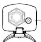
Figure 1
Key to force sending data to the devices
Led for signaling device status

Figure 2
REFERENCE STANDARDS
Compliance with Community Directives:
2014/30/EU (EMCD)
2014/53/EU (RED)
is declared with reference to the following harmonized standards:
• EN 60950-1
• ETSI EN 301 489-1, ETSI EN 301 489-3, ETSI EN 300 440-1, ETSI EN 300 440-2
- EN 60950-1 - ETSI EN 301 489-1, ETSI EN 301 489-3, ETSI EN 300 440-1, ETSI EN 300 440-2

Brand : ABB
Model : DY GPS
Category : Gps