
KH 120 D - Loudspeaker NEUMANN - Free user manual and instructions
Find the device manual for free KH 120 D NEUMANN in PDF.


| Product Type | Professional Active Studio Monitor |
| Brand | Neumann |
| Model | KH 120 D |
| Dimensions (H x W x D) | 277 x 182 x 220 mm (10 7/8 x 7 1/8 x 8 5/8 in) |
| Weight | 6.5 kg (14 lbs 5 oz) |
| Power Supply | 100-240 V~, 50/60 Hz |
| Power Consumption (Idle / Full Output) | 25 W / 200 W |
| Amplifier Power (Woofer + Tweeter) | 50 W + 50 W continuous, 80 W + 80 W peak |
| Frequency Response (-3 dB free field) | 52 Hz – 21 kHz |
| Maximum SPL (Full Space / Half Space at 3% THD, 1 m) | 105.1 dB / 111.1 dB |
| Drivers | Woofer: 130 mm (5.25"), Tweeter: 25 mm (1") |
| Crossover Frequency / Slope | 2.0 kHz, 24 dB/oct (4th order) |
| Analog Input | XLR, electronically balanced, impedance 10/20 kΩ |
| Digital Input (KH 120 D) | AES3 or S/P-DIF via BNC, 75 Ω |
| Digital Features | Selectable subframe A/B/A+B, delay up to 409.5 ms, lip sync compensation |
| Acoustical Controls | Bass (0 to -7.5 dB), Low-Mid (0 to -4.5 dB), Treble (+1 to -2 dB) |
| Output Level Switch | 94, 100, 108, 114 dB SPL |
| Input Gain Control | 0 to -15 dB |
| Protection Circuitry | Limiter (low, high), infrasonic filter at 30 Hz |
| Mounting Options | Two M8 threaded inserts on rear, multiple brackets available |
| Color | Anthracite (RAL 7021) or White (RAL 9016) |
| Cleaning | Disconnect from mains, use soft dry cloth |
| Safety Features | Ground lift switch, EMC compliant, magnetic field warning |
Frequently Asked Questions - KH 120 D NEUMANN
User questions about KH 120 D NEUMANN
0 question about this device. Answer the ones you know or ask your own.
Ask a new question about this device
Download the instructions for your Loudspeaker in PDF format for free! Find your manual KH 120 D - NEUMANN and take your electronic device back in hand. On this page are published all the documents necessary for the use of your device. KH 120 D by NEUMANN.
USER MANUAL KH 120 D NEUMANN
natural_image
Black studio audio amplifier with two speakers and a speaker grille (no visible text or symbols)Contents
Important safety instructions 4
The KH 120 studio monitor....6
Delivery includes 6
Product overview 7
Installing and connecting the KH 120 9
Preparing the loudspeakers 9
Preparing the room....9
Positioning the loudspeakers....10
Connecting audio signals....11
Connecting/disconnecting the KH 120 to/from the mains power supply....14
Configuring and using the KH 120....14
Switching the KH 120 on/off ....14
Adjusting the frequency response 14
Adjusting the acoustic level 15
Compensating for video delay (lip sync) 16
Compensating for listening distance differences (time-of-flight) .....16
Activating ground lift....17
Adjusting the brightness of the Neumann logo ....18
Cleaning and maintaining the KH 120 .... 18
Troubleshooting 18
Specifications 19
Accessories 21
Appendix
System Block Diagram ....I
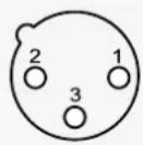
Pin assignment of the XLR socket. I
Acoustical Measurements ..... I
Installation angles IV
Delay Lookup Table....v
Important safety instructions
- Read these instructions.
-
Keep these instructions. Always include these instructions when passing the product on to third parties.
-
Heed all warnings.
-
Follow all instructions.
-
Do not use this apparatus near water.
-
Only clean the product when it is not connected to the mains power supply. Clean only with a dry cloth.
-
Always ensure a free air flow around the cooling fins on the rear of the product. Do not block any ventilation openings. Install in accordance with the manufacturer's instructions.
-
Do not install near any heat sources such as radiators, heat registers, stoves, or other apparatus (including amplifiers) that produce heat.
-
Do not defeat the safety purpose of the polarized or grounding-type plug. A polarized plug has two blades with one wider than the other. A grounding type plug has two blades and a third grounding prong. The wide blade or the third prong are provided for your safety. If the provided plug does not fit into your outlet, consult an electrician for replacement of the obsolete outlet.
-
Protect the power cord from being walked on or pinched, particularly at plugs, convenience receptacles, and the point where they exit from the apparatus.
-
Only use attachments/accessories specified by the manufacturer.
-
Use only with the cart, stand, tripod, bracket, or table specified by the manufacturer, or sold with the apparatus. When a cart is used, use caution when moving the cart/apparatus combination to avoid injury from tip-over.

-
Unplug this apparatus during lightning storms or when unused for long periods of time.
-
Refer all servicing to qualified service personnel. Servicing is required when the apparatus has been damaged in any way, such as power supply cord or plug is damaged, liquid has been spilled or objects have fallen into the apparatus, when the apparatus has been exposed to rain or moisture, does not operate normally, or has been dropped.
-
To completely disconnect this apparatus from the AC mains, disconnect the power supply cord plug from the AC receptacle.
-
WARNING: To reduce the risk of fire or electric shock, do not expose this apparatus to rain or moisture.
-
Do not expose this equipment to dripping or splashing and ensure that no objects filled with liquids, such as vases, are placed on the equipment.
-
The mains plug of the power supply cord shall remain readily accessible.
Installation • Ensure that the room in which you use this product is wired in accordance with the local electrical code and checked by a qualified inspector.
- Only use the product indoors.
- Do not install the product in hot, humid, or excessively dusty locations, in direct sunlight or in locations where it is exposed to externally generated vibrations.
- Do not place burning objects (e.g. candles) on top of or near the product.
- If condensation has formed on the product, e.g. because it was moved from a cold environment to a warm one, allow the product to acclimatize to room temperature before using it.
- Do not overload wall outlets and extension cables as this may result in fire and electric shock.
Danger due to high sound pressure levels

WARNING
Danger of hearing damage due to sudden high sound pressure levels!
Audio signals that are present at switch-on of the product or that can be present during operation, can create sudden, very high sound pressure levels which can damage your hearing.
Always lower the output level of the audio source before connecting it to the loudspeaker or starting it (pressing "play").
This loudspeaker can be used for commercial purposes. Commercial use is subject to the rules and regulations of the trade association responsible. Neumann, as the manufacturer, is therefore obliged to expressly point out possible health risks arising from use. This loudspeaker is capable of producing sound pressure levels exceeding 85 dB(A) SPL. This is the sound pressure corresponding to the maximum permissible level which is by law (in some countries) allowed to affect your hearing for the duration of a working day (8 hours). It is used as a basis according to the specifications of industrial medicine. Higher sound pressure levels and/or longer durations can damage your hearing. At higher sound pressure levels, the duration must be shortened in order to prevent hearing damage. The following are signs that you have been subjected to excessive sound pressure levels for too long a time:
- You can hear ringing or whistling sounds in your ears.
- You have the impression (even for a short time only) that you can no longer hear high frequencies (temporary threshold shift).
Magnetic fields

WARNING
Interference due to magnetic fields!
This product generates a permanent magnetic field (> 1.5 mT) that can interfere with cardiac pacemakers and implanted defibrillators (ICDs).
Always maintain a distance of at least 4" (10 cm) between the loudspeaker and the cardiac pacemaker or implanted defibrillator.
Hazard warnings on the rear of the product
The label shown on the right is attached to the rear of the product.
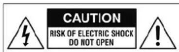
The symbols on this label have the following meaning:
Presence of uninsulated dangerous voltage within the product's enclosure that may be of sufficient magnitude to constitute a risk of fire or electric shock.
Never open the product or remove the grilles fitted to the product as there is a risk of electric shock. There are no user serviceable parts inside. Refer servicing to your Neumann service partner.
Read and follow the safety and operating instructions contained in the operating manual.

CAUTION
RISK OF ELECTRIC SHOCK DO NOT OPEN

Intended use
Intended use of the product includes:
- having read this operating manual, especially the chapter "Important safety instructions",
- using the product within the operating conditions and limitations described in this operating manual.
“Improper use” means using the product other than as described in this operating manual, or under operating conditions which differ from those described herein.
The KH 120 studio monitor
Thank you for purchasing a Neumann studio monitor. The KH 120 features a Mathematically Modeled Dispersion™ Waveguide (MMD™), flexible acoustical controls, various input options and an extensive range of mounting hardware. This allows the loudspeaker to be used in diverse acoustical conditions, with any source equipment and in a wide variety of physical locations. The KH 120 represents the latest in acoustic and electronic simulation and measurement technologies to ensure the most accurate sound reproduction possible.
Depending on the size, Neumann's two-way loudspeaker systems are designed for use as near field monitors or as rear loudspeakers in larger multi-channel systems. They can be used in project, music, broadcast, and post production studios for tracking, mixing, and mastering.
Delivery includes
1 KH 120 A or KH 120 D
4 Self-adhesive feet
1 Quick guide
1 Safety guide
Delivery also includes European, UK or US mains cables
Product overview
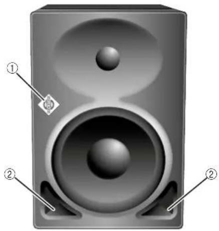
Front panel
natural_image
3D rendering of a speaker with two speakers and a button, labeled with numbers ① and ② (no text or symbols on the speaker itself)① Neumann logo
- lights up white: loudspeaker is switched on and ready for operation
- flashes red: loudspeaker's protection system is active or
A digital signal is selected via the SIGNAL SELECT rotary switch ⑭ but there is no valid digital signal connected
② Bass reflex ports
Bottom KH 120 A
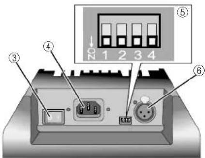
③ On/off switch
④ IEC mains socket with protective ground contact
⑤ DIP switches [1]–[4]
[1] Switches the Neumann logo on/off
[2] Dims the Neumann logo
[3] No function
[4] Connects/disconnects ground lift
⑥ ANALOG INPUT socket (XLR)
Bottom KH 120 D
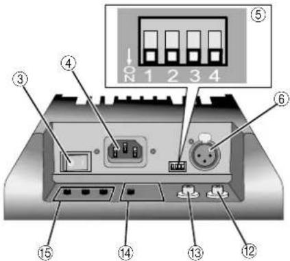
③ On/offswitch
④ IEC mains socket with protective ground contact
⑤ DIP switches [1]–[4]
[1] Switches the Neumann logo on/off
[2] Dims the Neumann logo
[3] No function
[4] Connects/disconnects ground lift
⑥ ANALOG INPUT socket (XLR)
⑫ AES3 OUTPUT socket (BNC)
⑬ AES3 INPUT socket (BNC)
⑭ SIGNAL SELECT rotary switch
⑮ DELAY rotary switches
Back panel KH 120 A
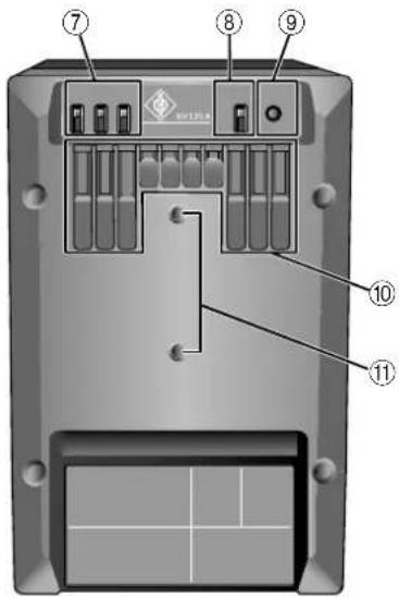
⑦ ACOUSTICAL CONTROLS switches
⑧ OUTPUT LEVEL switch
⑨ INPUT GAIN control
⑩ Coolingfins
⑪ Threaded inserts for Neumann mounting hardware
Back panel KH 120 D
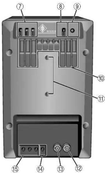
⑦ ACOUSTICAL CONTROLS switches
⑧ OUTPUT LEVEL switch
⑨ INPUT GAIN control
⑩ Coolingfins
⑪ Threaded inserts for Neumann mounting hardware
⑫ AES3 OUTPUT socket (BNC)
⑬ AES3 INPUT socket (BNC)
⑭ SIGNAL SELECT rotary switch
⑮ DELAY rotary switches
Installing and connecting the KH 120

CAUTION
Danger of injury and material damage due to tipping/dropping of the product!
If improperly mounted, the product and/or the mounting hardware (e.g. rack) can tip over or drop down.
Always have the product mounted by a qualified specialist according to local, national and international regulations and standards.
Use the mounting systems recommended by Neumann and always provide sufficient additional protection against tipping or dropping!
CAUTION
Damage to the product due to overheating!
If air cannot circulate properly around the cooling fins on the rear of the product, the amplifier(s) may overheat leading to premature activation of the thermal protection system which limits the maximum output level of the loudspeaker. In rare cases, damage to the product may also occur.
Never cover the cooling fins.
When installing the product into tight spaces such as wall recesses, maintain an air gap of at least 5 cm (2") around the top, rear and side panels of the product and provide sufficient air circulation. If necessary, use forced-air cooling (e.g. in OB vans).

For information on installation, please refer to the supplied "Getting Started Quickly" supplement. This will help you set up the loudspeakers in a way that will give you the best acoustic performance from the system.
For further information on setting up loudspeakers, please refer to the “Questions & Answers” section on the product page at www.neumann.com.
For more information on building systems using Neumann loudspeaker products, please refer to the Product Selection Guide at www.neumann.com
Preparing the loudspeakers
CAUTION
Risk of staining surfaces!
Some surfaces treated with varnish, polish or synthetics may suffer from stains when they come into contact with other synthetics. Despite a thorough testing of the synthetics used by us, we cannot rule out the possibility of staining.
Do not place the loudspeaker on delicate surfaces.
To place the loudspeaker on a flat surface:
▶ Attach the supplied self-adhesive feet to the bottom of the cabinet.
This reduces the risk of scratching the surface and acoustically isolates the loudspeaker from the surface.
Preparing the room
▶ Arrange all acoustically relevant surfaces and objects symmetrically on either side of the listening axis of the room (left/right).
Minimize the sound that is reflected back to the listening position by using angled surfaces and/or acoustical treatment.

This product has been optimized for use in recording studios. In order not to affect the quality of reproduction, make sure that the product is used in an EMC environment.
Distances
Arranging the loudspeakers at an angle
Positioning the loudspeakers
Carry out the following steps very accurately, since the more accurate the physical arrangement of the loudspeakers in the room, the more accurate the reproduction will be at the listening position.
Observe the recommended distances between the loudspeakers and your listening position (imperial dimensions are approximate):
• Minimum: 0.75 m (2.5')
- Recommended: 1.0–2.0 m (3'–6')
• Maximum: 4.0 m (12')
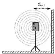
Avoid positioning the loudspeaker at a distance “ d_wall ” of 0.8 to 2 m from the wall behind the loudspeaker. When positioning bass managed loudspeakers, avoid a distance “ d_wall ” of 0.8 to 1 m from a solid wall behind the loudspeaker. Similarly, avoid these distances from solid side walls or a solid ceiling. Respecting these positioning limitations reduces the chances of dips in the low frequency response (comb filtering) caused by strong reflections.
©opy the diagram "Installation angles" that can be found at the end of this operating manual.
Place the diagram at the listening position or center of the listening area.
Using a tape measure, place the loudspeakers at the same distance from the center of the diagram "Installation angles". To ensure good imaging, do this at an accuracy of at least 1 cm ( 12 ").
If the loudspeakers cannot be placed at the same distance from the listening position, compensate for distance differences >1cm (^1_/2^ ) by delaying closer loudspeakers by 30~ s / cm (76 s / inch ).
If you are using the KH 120 D:
KH 120 D
▶ Use the DELAY rotary switches ⑮ to compensate for distance differences (see page 16).

The DELAY rotary switches 15 allow for corrections with a resolution of 3.44 cm (1 3/8"), any small remaining time-of-flight adjustment should be made by moving the loudspeaker cabinet.
Check the location of the loudspeaker cabinet. This depends on the application:
• 2.0 systems (stereo): ±30°, plus optional subwoofer(s)
- 5.1 systems:
ITU-R BS.775-1: 0°, ±30°, ±110° (±10°), plus optional subwoofer(s)
(center, front left/right, surround left/right)
ANSI/SMPTE 202M: 0^ , ± 22.5^ , arrays to the surround left and to the surround right, plus optional subwoofer(s)
- 7.1 systems: 0^ , ± 30^ , ± 90^ , ± 150^ , plus optional subwoofer(s)
(center, front left/right, side left/right, back left/right)
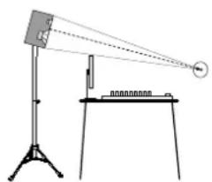
The acoustical axis of the KH 120 is located at the midpoint of the bass and tweeter drivers.
Always point the acoustical axis, in the horizontal and vertical planes, towards the listening position.
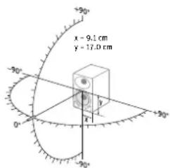

The acoustical axis is a line perpendicular to the loudspeaker's front panel along which the microphone was placed when tuning the loudspeaker's crossover during design. Pointing the acoustical axis, in the horizontal and vertical planes, towards the listening position or center of the monitoring area will give the best measured and perceived sound quality.
natural_image
Simple line drawing of a physics experiment setup with a tilted screen, tripod, and scale (no text or symbols)Position the loudspeaker so that there is a direct line of sight from the listening position to the bass and tweeter drivers.
Connecting audio signals
Always use good quality cables with the correct impedance and appropriate termination to avoid signal drop outs and to achieve the maximum cable lengths shown below:
| Signal (connector) | Impedance Cable length Connection | ||
| Analog (RCA) low up to 10 m | (30') | via an adapter (RCA-XLR) to the ANALOG INPUT socket (XLR) 6 (see below) | |
| Analog (XLR) low up to 100 m | (300') | directly to the ANALOG INPUT socket (XLR) 6 (see below) | |
| AES3 (BNC) 75 Ω up to 100 m | (300') | directly to the AES3 INPUT socket (BNC) 13 (see page 12) | |
| AES3 (XLR) 110 Ω up to 100 m | (300') | via an impedance converter and an adapter (XLR-BNC) to the AES3 INPUT socket (BNC) 13 (see page 12) | |
| S/P-DIF (RCA) 75 Ω up to 10 m | (30') | via an adapter (RCA-BNC) to the AES3 INPUT socket (BNC) 13 (see page 12) | |
Connecting XLR cables
Connecting analog signals to the KH 120 A and the KH 120 D
▶Only connect analog signals to the KH 120 A.
Connect the left and right output of your analog audio source to the XLR input sockets ⑥ of the respective loudspeaker.
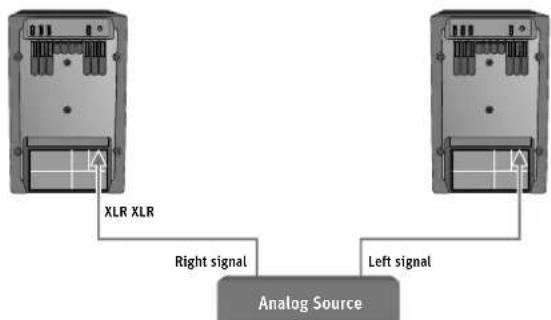
▶ Use an XLR adapter (not supplied) to connect unbalanced cables (e.g. RCA cables).
▶ Use the following wiring if you want to make your own XLR adapter:
| Wiring Pin Signal | |||
| Source (RCA) | Loudspeaker (XLR-M) | 1 | Audio ground |
| 2 | Signal + | ||
| 3 | Signal - | ||
If there is a humming sound from the loudspeaker, activate ground lift to disconnect pin 1 of the ANALOG INPUT socket (XLR) ⑥ from the loudspeaker's chassis ground.
Connecting AES cables
Connecting digital signals to the KH 120 D
KH 120 D
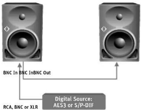
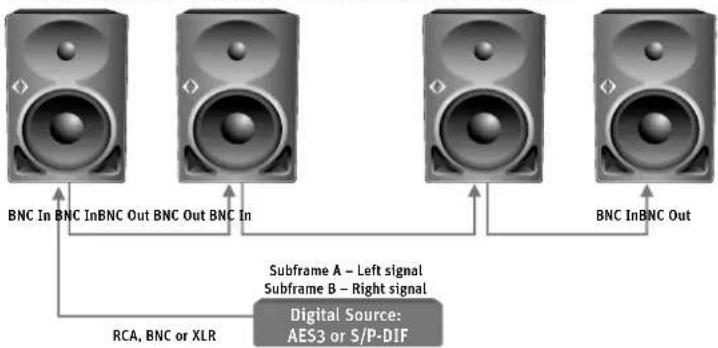
Connect the digital AES3 or S/P-DIF-output signal of your audio source to the AES3 INPUT socket ⑬ of the respective KH 120 D. See picture below.

The KH 120 D loudspeaker only supports non-encoded AES3 and S/P-DIF signals. Encoded signals such as MP3, DTS or Dolby Digital are not supported.
Make an appropriate setting ("DIGITAL A" or "DIGITAL B") on the SIGNAL SELECT rotary switch ⑭. The setting depends on the signal channel order and the loudspeaker position.

Only one cable is needed for uncompressed AES3 and S/P-DIF digital signals (single-wire mode). They contain two audio channels: "subframe A" and "subframe B". Usually, the audio channels are:
| Subframe A Subframe B | |
| Left Right | |
| Center LFE | |
| Surround left Surround right | |
| Back left Back right |
A clock input is not required because loudspeakers are not audio sources and the converters are clocked to a very stable internally generated clock source.
To connect an additional loudspeaker:
▶ Use the AES3 OUTPUT socket ⑫. See picture below.
Make an appropriate setting ("DIGITAL A" or "DIGITAL B") on the SIGNAL SELECT rotary switch ⑭.
flowchart
graph TD
    A["Speaker 1"] -->|BNC In BNC InBNC Out| C["Digital Source: AES3 or S/P-DIF"]
    B["Speaker 2"] -->|RCA, BNC or XLR| C
    C --> A
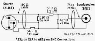
Use a Neutrik NADITBNC-F impedance and level converter (not supplied) for XLR to BNC conversions of AES3-signals. This method brings impedance matching, level matching and source-receiver isolation. The Neutrik NADITBNC-F converter is guaranteed to work up to 48 kHz. Only one converter is needed per digital signal cable.
▶ Use the following wiring if you want to make your own converter:
CAUTION
Damage to the product due to high AES3 signal levels!
AES3 signal levels in XLR cables are much too high for the AES3 INPUT socket (BNC) ⑬. If you connect such signals without reducing the signals' level, damage to the product will occur.
▶Always make sure that your converter is able to match impedance and level.
KH 120 D
Wiring Pin Signal
1 Shield
2 Signal +
3 Signal -
This method brings impedance matching and level matching, but no source-receiver isolation. Use a resistor network to passively attenuate the XLR signal from 3.1 V down to 0.42 V and change the impedance from 110 Ω to 75 Ω.
Connecting multiple KH 120 D loudspeakers together
Use the AES3 OUTPUT socket ⑫ and INPUT socket ⑬. T-pieces are not required – see picture below.
Make an appropriate setting ("DIGITAL A" or "DIGITAL B") on the SIGNAL SELECT rotary switch ⑭.
End of the line external termination is not required as the AES3 INPUT socket (BNC) ^13 already has an internal 75 Ω termination.
Set back panel switch to "DIGITAL A" Set back panel switch to "DIGITAL B"
flowchart
graph TD
    A["Speaker 1"] -->|BNC In BNC Out BNC Out BNC In| C["Digital Source: AES3 or S/P-DIF"]
    B["Speaker 2"] -->|BNC InBNC Out| C
    D["Speaker 3"] -->|Subframe A - Left signal Subframe B - Right signal| C
    E["Speaker 4"] -->|BNC InBNC Out| C
    F["RCA, BNC or XLR"] --> C
    style C fill:#f9f,stroke:#333
Setting the SIGNAL SELECT rotary switch ⑭
▶Select one of the following settings, depending on your needs:
| Setting Meaning | |
| ANALOG | XLR input socket 6 |
| DIGITAL A | Digital subframe A, AES3 INPUT socket 13 |
| DIGITAL B | Digital subframe B, AES3 INPUT socket 13 |
| DIGITAL A+B | Digital subframe A summed with digital subframe B and a 6 dB attenuation, AES3 INPUT socket 13 |
Each of these can be selected with and without delay added, so it is very quick to bypass the delay.
The digital output is a copy of the digital input signal which can be used to feed the digital signal onto other loudspeaker or products. There is no digital output from the AES3 OUTPUT socket (BNC) ⑫ when an analog signal is connected to the ANALOG INPUT socket ⑥, therefore the KH 120 D cannot be used as an analog-to-digital converter.
Connecting/disconnecting the KH 120 to/from the mains power supply
To connect the KH 120 to the mains power supply:
Make sure that the on/off switch ③ is set to "OFF".
Connect the IEC connector of the supplied mains cable to the mains socket ④.
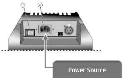
Connect the mains plug of the mains cable to a suitable wall socket.
To disconnect the KH 120 from the mains power supply:
▶ Set the on/off switch ③ to "OFF".
▶Pull the mains plug out of the wall socket.
Configuring and using the KH 120
Switching the KH 120 on/off
natural_image
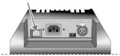
Back view of a computer monitor showing internal components including an RJ4 port and two connected ports (no text or symbols visible)▶ Set the on/off switch to:
- "ON" to switch on the loudspeaker. The Neumann logo lights up, provided that is has not been switched off (see page 18).
- "OFF" to switch off the loudspeaker. The Neumann logo goes off.

There is a five second delay before sound can be heard from the loudspeaker in order to avoid noises (pops) from preceding equipment switched on at the same time. Conversely, switching off the loudspeaker immediately mutes the audio.
Adjusting the frequency response
When all its acoustical controls are set to 0 dB, the KH 120 loudspeaker is designed to have a flat frequency response in anechoic conditions. When the loudspeaker is installed in your monitoring environment, the response changes. The same loudspeaker installed in different positions in the same room may require different acoustical control settings. In a symmetrical installation, left/right pairs (front or back) will probably have the same acoustical settings.
Before using your loudspeaker system for the first time, calibrate the frequency response of the loudspeakers in the room in order to obtain the desired response.
▶Repeat the above step if you change the physical conditions in your studio.
▶At your listening position, determine the frequency response of each loudspeaker.
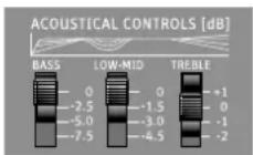
Use the ACOUSTICAL CONTROLS switches ⑦ to adjust the frequency response. Recommended frequency responses:
• Studio applications: flat
• Film applications: X-curve shape (see ANSI/SMPTE 202M)
• Home applications: subjective evaluation
| ACOUSTICAL CONTROLS switches 7 | Function Possible settings | |
| Bass Compensates for acoustical loading in the low frequency range due to nearby large solid boundaries (e.g. walls). | 0, -2.5, -5, -7.5 dB | |
| Low-Mid Compensates for acoustical loading in the low-mid frequency range due to nearby large solid objects (e.g. mixing consoles or desks). | 0, -1.5, -3, -4.5 dB | |
| Treble Compensates for insufficient or excessive high-frequency damping in the room. | +1, 0, -1, -2 dB | |
The following settings can be used as a starting point for further adjustment:
| Loudspeaker position Acoustical controls | |||
| Bass Low | Mid Treble | ||
| In a corner -7.5 dB -1.5 dB - | |||
| Next to an acoustically solid wall (e.g. brick, concrete) | -5 dB | - | - |
| Next to an acoustically soft wall (e.g. gypsum) | -2.5 dB | - | - |
| Free standing in an untreated room | -2.5 dB | - | -1 dB |
| Free standing in a well-treated room | - | - | - |
| In a small room with strong side wall reflections | -5 dB | 0 dB | - |
| Near a small desktop or small reflecting surface* | - | -1.5 dB | - |
| Near a large desktop or large reflecting surface* | - | -3 dB | - |
* Use these settings in addition to one of the top settings
Adjusting the acoustic level
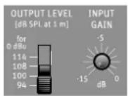
On your KH 120 loudspeakers, set the OUTPUT LEVEL switch ⑧ to 94 dB SPL and the INPUT GAIN control ⑨ to -15 dB.
Play a broadband pink noise test signal that is set to -18 dBFS (Europe) or -20 dBFS (USA) on the mixing console's output level meters.
Measure the sound pressure level at the listening position using a sound level meter with the following settings:
- "C"-weighted
- slow integration time
▶ Set the OUTPUT LEVEL switch ⑧ and INPUT GAIN control ⑨ of your loudspeakers so that the desired acoustic level is obtained.
Recommended sound pressure levels:
| Application Sound pressure level | |
| Film 85 dB(C) | |
| Broadcast 79 to 83 dB(C) | |
| Music No defined reference levels | |
If the Neumann logo flashes red, the loudspeaker's protection system has been activated. To avoid this and achieve the desired output level, use larger loudspeakers or add a bass managed subwoofer to the system.
Examples of sound pressure levels as a function of the input and output level of the KH 120:
| Input signal dBu | 0(0.775 V) | 0(0.775 V) | +4(1.23 V) | -20(77.5 mV) |
| INPUT GAIN control 9dB | 0 | -15 | -4 | -15 |
| OUTPUT LEVEL switch 8dB SPL | 100 100 94 114 | |||
| Sound pressure leveldB SPL at 1 m | 100 85 94 79 | |||
Compensating for video delay (lip sync)
KH 120 D
Signal processing in LCD, Plasma and LED screens, digital projectors with LCD or DLP chips, and video processors used in broadcast centers delays the video signal.
The delay is disturbing when audio leads video by more than 20 ms or lags by more than 40 ms.
To compensate for the video signal delay, the audio signal of the KH 120 D can be delayed by up to 409.5 ms, which is 10.2 frames at 40 ms/frame or 12.3 frames at 33 ms/frame. The same value should be used for all loudspeakers in the system.

Please consider the information on latency on page 17.
Compensating for listening distance differences (time-of-flight)
Loudspeakers placed at different distances suffer from time-of-flight differences which affects imaging. The DELAY resolution is small enough (0.1 ms) that the delay can be used for time-of-flight adjustment (3.44 cm or 1 3/8" steps). To compensate for the time-of-flight delay, the audio signal can be delayed by up to 409.5 ms, which is 140.87 m (462' 2").
Loudspeakers positioned closer to the listening position should be delayed to be the same as the furthest loudspeaker from the listening distance.
Example
Loudspeaker A listening distance: 1.50 m
Loudspeaker B listening distance: 1.65 m
Time-of-flight difference: 0.15 m
So loudspeaker A should be delayed by the time equivalent of 0.15 m which is 0.436 ms (0.15 m / 3.44 cm x 0.1 ms). The nearest setting of the DELAY rotary switches 15 is 0.4 ms, so set the 0.1 ms switch to position 4.

Please consider the information on latency on page 17.
KH 120 D
If a video delay compensation has already been made, add the time-of-flight difference (here: 0.4 ms) to the setting already made.
Example
Video delay compensation on loudspeaker A: 2 x 40 ms/frame Desired time-of-flight compensation for loudspeaker A: 0.4 ms
Time-of-flight compensation: 80.4 ms
This delay value can be made with these switch settings: 3 x 25.6 ms, 2 x 1.6 ms, 4 x 0.1 ms.

The latency of the analog-to-digital and digital-to-analog converters should be taken into account when using the DELAY rotary switches ^15 for time-of-flight compensation. For the digital-to-analog conversion (input signal via digital connector), the latency is dependent on the sample rate (values can be seen in the Specifications table on page 20). The analog-to-digital-to-analog conversion (input signal via analog connector) is fixed at 0.54 ms.
For time-of-flight compensation delay, calculate the desired delay value then subtract the appropriate latency depending on the input signal and sample rate, and then set the needed additional delay using the delay switches on the back panel.
Example:
Distance compensation for 1 m: 1 m / 344 m/s = 2.91 ms: 2.91 ms Digital input signal, sample rate: 48 kHz, latency: 0.85 ms
2.06 ms
Delay settings: 0 x 25.6 ms, 1 x 1.6 ms, 5 x 0.1 ms (equals 2.1 ms, which is the nearest value)

For video delay compensation, converter latency can be ignored as it is insignificant compared to long video signal delays.
To help with choosing a delay setting there is a set of lookup tables at the end of this operating manual. Also Neumann has made a delay calculator which is available at www.neumann.com.
Activating ground lift
If there is humming or buzzing noise coming from the loudspeaker, first search for the cause of the noise:
Disconnect all input and output signal cables from the loudspeaker.
If the noise goes away, it is probably coming from the audio source or source cabling.
It might be possible to eliminate the noise by disconnecting the ground from the input signals (activating ground lift).
To activate ground lift:
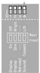
Reconnect the signal cables and set the DIP switch [4] ("Ground lift") ⑤ to "Lift".
This internally disconnects pin 1 of the ANALOG INPUT socket (XLR) ⑥ from the loudspeaker's chassis ground (see diagram "Pin assignment of the XLR socket" on page 11).

For safety reasons, the electronics chassis ground is always connected to the mains power earth pin.
Adjusting the brightness of the Neumann logo

WARNING
Danger of hearing damage due to unexpected high sound pressure levels!
If the Neumann logo is switched off, it is not obvious whether the product is switched on or off. In this case, unexpected high sound pressure levels can cause hearing damage.
Always set the audio sources connected to the loudspeaker to a low output level before they deliver an audio signal.
If you switch off or dim the Neumann logo, mention this to everyone who works with this loudspeaker or the connected audio sources.
To dim or switch off the Neumann logo in low light level environments or when the loudspeaker is placed behind an acoustically transparent screen:
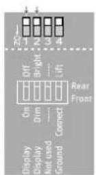
▶ Set the DIP switch [1] to:
- "On" to switch on the Neumann logo.
- "Off" to switch off the Neumann logo.
▶ Set the DIP switch [2] to:
- "Dim" to dim the Neumann logo.
• "Bright" to not dim the Neumann logo.

When the loudspeaker's protection system is active or invalid digital signals are connected to the KH 120 D, the Neumann logo's color changes from white to red. The brightness of this red limiter indication can be adjusted by means of the DIP switch [2] ("Dim" or "Bright"). However, you cannot switch off the limiter indication, as it appears independent of the position of the DIP switch [1].
Cleaning and maintaining the KH 120
CAUTION
Damage to the product caused by liquids!
Liquids entering the product can cause a short-circuit in the electronics and damage or even destroy the product.
Keep all liquids away from the product!
Before cleaning, disconnect the product from the mains power supply.
▶ Use a soft, dry, and lint-free cloth to clean the product.
Troubleshooting
| Problem Cause Solution | ||
| The Neumann logo is off, no sound is heard from the KH 120 | The KH 120's main fuse has blown. | Have the product checked by an authorized Neumann service partner. |
| The Neumann logo is off or not clearly visible, but sound is heard from the KH 120 | The Neumann logo is switched off or dimmed. | Switch on the Neumann logo and switch off the dimming (see page 18). |
| The Neumann logo is flashing red but there is no sound | A DIGITAL signal is selected on the SIGNAL SELECT rotary switch 14 but there is no valid audio signal connected to the digital input. | Connect a valid signal to the digital input, check the cabling, or set the SIGNAL SELECT rotary switch 14 to ANALOG. |
| There is hum or buzz coming from the KH 120 when the audio cable is connected. | Bad cabling or ground loop in the installation. | Check all cabling to eliminate the cause of the problem, change from unbalanced to balanced cabling, or use the ground lift switch (see page 17). |
For further information, please refer to the "Questions & Answers" section on the product page at www.neumann.com.
Specifications
| Acoustics | |
| -3 dB free field frequency response 52 Hz to 21 kHz, ±3 dB | |
| Pass band free field frequency response 54 Hz to 20 kHz, ±2 dB | |
| Self-generated noise(with input gain set to 100 dB for 0 dBu) | <20 dB(A) at 10 cm |
| Total harmonic distortion < 0.5 % at 95 dB SPL at 1 m >100 Hz | |
| Max. SPL in full space / calc. in half space at 3 % THD at 1 m, averaged between 100 Hz and 6 kHz | 105.1 dB SPL / 111.1 dB SPL |
| Bass capability:Max. SPL in half space with 3 % THD at 1 m,averaged between 50 Hz and 100 Hz | 104.8 dB SPL |
| Max. short term SPL with IEC-weighted noise(IEC 60268-5) at 1 m, in typical listening conditions | 107 dB(C) SPL |
| Max. short term SPL with music material at 2.3 m,in typical listening conditions (pair) | 97 dB(C) SPL (full range)104 dB(C) SPL (with subwoofer) |
| Max. long term SPL with pink noise at 2.3 m,in typical listening conditions (single/pair) | 88/93 dB(C) SPL (full range)89/94 dB(C) SPL (with subwoofer) |
| Electronics | |
| Woofer amplifier, continuous (peak) output power 50 W (80 W), THD and noise < 0.1 %with deactivated limiter | |
| Tweeter amplifier, continuous (peak) output power 50 W (80 W), THD and noise < 0.1 %with deactivated limiter | |
| Controller design analog, active | |
| Crossover frequency; crossover slope 2.0 kHz; 24 dB/oct., 4 | ^th order |
| ACOUSTICAL CONTROLS switches | BASS: 0, -2.5, -5, -7.5 dBLOW-MID: 0, -1.5, -3, -4.5 dBTREBLE: +1, 0, -1, -2 dB |
| Protection circuitry | Limiter: low, high |
| Infrasonic filter frequency; slope | 30 Hz; 6 dB/oct. |
| Analog input | |
| Input type | XLR, electronically balanced |
| Input Impedance | depending on the position of the OUTPUT LEVEL switch 8: |
| 114 dB SPL 20 kΩ | |
| 108 dB SPL 10 kΩ | |
| 100 dB SPL 20 kΩ | |
| 94 dB SPL 10 kΩ | |
| Input gain control (sensitivity) | 0 dB to -15 dB |
| OUTPUT LEVEL switch | 94, 100, 108, 114 dB SPL |
| CMRR > 56 dB, 100 Hz to 10 kHz (ANALOG mode) | > 56 dB, 100 Hz to 12 kHz (ANALOG DELAYED mode) |
| Maximum input level 24 dBu (ANALOG mode) | 18 dBu (ANALOG DELAYED mode) |
| Digital input/output (KH 120 D only) | |
| Signal format BNC AES3, S/P-DIF | |
| Impedance BNC, unbalanced 75 Ω (input and output) | |
| Input switching Analog/Digital A/Digital B/Digital A+B | |
| Digital converter: resolution 16 ... 24-bit | |
| Digital converter: sampling rates [kHz]* | 22.05, 24, 32, 44.1, 48, 64, 88.2, 96, 176.4, 192 |
| Digital sensitivity -18 dBFS = 100 dB SPL at 1 m | |
| Dynamic range: A-D-A, D-A | > 116 dB(A), 123 dB(A) |
| THD+N: analog delayed, digital | < -104 dB, < -106 dB |
| Maximum delay: time / distance | 409.5 ms / 140.87 m (462' 2") |
| Maximum delay: audio-video synchronization (lip sync) | 10.2 at 40 ms/frame12.3 at 33 ms/frame |
| Minimum delay resolution: time / distance | 0.1 ms / 3.44 cm (1 3/8") |
| Latency D-A (with delay = 0 ms)** | 1.84 ms at 22.05 kHz1.70 ms at 24 kHz1.28 ms at 32 kHz0.93 ms at 44.1 kHz0.86 ms at 48 kHz0.64 ms at 64 kHz0.47 ms at 88.2 kHz0.43 ms at 96 kHz0.24 ms at 176.4 kHz0.22 ms at 192 kHz |
| Latency A-D-A (with delay = 0 ms) | 0.54 ms |
| DELAY rotary switches 15 and SIGNAL SELECT rotary switch 14 setting acknowledgement | Neumann logo "Red" 3 flashes |
| Digital error/Loudspeaker's protection system is active | Neumann logo "Red" 1 flash |
| Product properties | |
| Power supply 100 to 240 V~, 50/60 Hz | |
| Power consumption (idle) KH 120 A: 20 W | KH 120 D: 25 W |
| Power consumption (full output AC) 200 W | |
| Dimensions (H x W x D) 277 x 182 x 220 mm (10 | ^7/_8 " x ^7/_8 " x ^85/_8 ") |
| Internal net volume/external volume 6.5 l/9.7 l | |
| Weight KH 120 A: 6.4 kg (14 lbs 2 oz) | KH 120 D: 6.5 kg (14 lbs 5 oz) |
| Drivers - woofer, tweeter magnetically shielded - 130 mm (5.25"), 25 mm (1") | |
| Threaded inserts for Neumann mounting hardware | 2 x M8 on rear panel with depth 15 mm ( ^5/_8 ") |
| Cabinet surface finish, Color | painted aluminium,Anthracite (RAL 7021) orWhite (9016) orother RAL color |
* These are the sample rates for which the delay setting value shown on the back panel is valid.
** Depending on the sample rate, this value should be added to the delay setting on the back panel to give the total delay.
Temperature
Operation and storage, unpacked +10 °C to +40 °C (+50 °F to +104 °F)
Transport and storage, packed in original packaging -25^ to +70^ (-13^ to +158^)
Relative humidity
Operation and storage, unpacked max. 75 % (non-condensing)
Transport and storage, packed in original packaging max. 90 % (non-condensing)
Acoustical measurements, block diagram and pin assignment
Additional technical data such as acoustical measurements, a block diagrams and the pin assignment of the XLR socket can be found at the end of this operating manual.
Accessories
Product Description
BKH 120 Soft carry bag for 1 pair of KH 120
FKH 120 Flight case for 1 pair of KH 120
LH 28 Tripod stand adapter
LH 29 TV spigot (lighting stand adapter)
LH 32 Wall L-bracket
LH 43 Surface mounting plate
LH 45 Wall bracket
LH 46 Adjustable ceiling drop adapter
LH 47 Mounting adapter plate
LH 48 Tripod adapter plate
LH 61 Adjustable L-bracket
LH 64 Omnimount/VESA adapter
LH 65 Table stand
System Block Diagram/System-Blockdiagramm/Synoptique Système/Diagrama de Bloques del Sistema
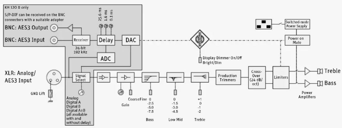
flowchart
graph LR
    A["Receiver"] --> B["Delay"]
    B --> C["DAC"]
    C --> D["Display Dimmer On/Off Bright/Dim"]
    D --> E["Switched-mode Power Supply"]
    E --> F["Power on Mute"]
    F --> G["Limiters"]
    G --> H["Treble"]
    G --> I["Bass"]
    J["XLR: Analog/AES3 Input"] --> K["Signal Select"]
    K --> L["Analog Digital A Digital B Digital A+B (all available with and without delay)"]
    L --> M["GND Lift"]
    M --> N["Receiver"]
    N --> O["24-bit 192 kHz"]
    O --> P["Delay"]
    P --> Q["DAC"]
    Q --> R["Display Dimmer On/Off Bright/Dim"]
    R --> S["Switched-mode Power Supply"]
    S --> T["Power Amplifiers"]
    T --> U["Treble"]
    T --> V["Bass"]
    W["CoarseFine Gain"] --> X["Bass"]
    X --> Y["0 -2.5 -5.0 -7.5"]
    Y --> Z["0 -1.5 -3.0 -4.5"]
    Z --> AA["+1 0 -1 -2"]
    AA --> AB["Production Trimmers"]
    AB --> AC["Cross-Over (24 dB/oct)"]
    AC --> AD["Limiters"]
    AD --> AE["Treble"]
    AD --> AF["Bass"]
Pin assignment of the XLR socket/Buchsenbelegung XLR/Brochage de la prise XLR/Asignación de la hembra XLR
1 Audio ground/Audio-Erdung/Masse audio/Toma de tierra de audio
2 Signal +/Signal +/Signal +/Señal +
3 Signal -/Signal -/Signal -/Señal -
Acoustical Measurements/Akustische Messungen/Mesures acoustiques/Mediciones Acústicas
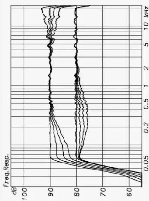
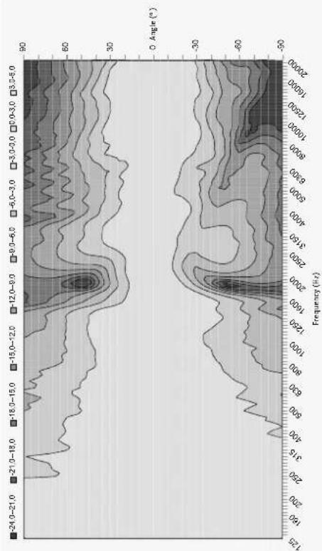
EN Below are acoustical measurements conducted in anechoic conditions at 1 m. Color versions of these graphs can be found on the appropriate product page of the web site.
DE Die folgenden akustischen Messungen wurden unter reflexionsarmen Bedingungen in 1 m Abstand durchgeführt. Farbversionen dieser Diagramme finden Sie auf den entsprechenden Produktseiten der Neumann Website.
FR Vous trouverez ci après les courbes correspondant aux mesures acoustiques effectuées en chambre sourde, à une distance de 1 mètre du moniteur. Vous retrouverez ces courbes, en couleur, dans la section appropriée de notre site Web.
ES Las siguientes mediciones acústicas se han realizado bajo condiciones de baja reflexión a una distancia de 1 m. Encontrará versiones a color de estos diagramas en las páginas correspondientes de los productos en la página web de Neumann.
Free-Field Response | Freifeld-Frequenzgang | Réponse en champ libre
Respuesta en frecuencia en campo libre
Group Delay | Gruppenlaufzeit | Temps de propagation de groupe Retardo de grupo
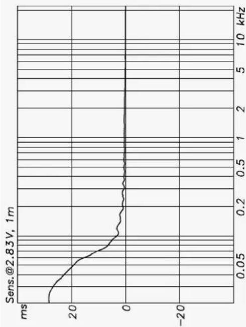
line
| Frequency (kHz) | Amplitude (ms) | | --------------- | -------------- | | 0.0 | 25.0 | | 0.05 | 15.0 | | 0.1 | 5.0 | | 0.2 | 2.0 | | 0.5 | 1.0 | | 1.0 | 0.5 | | 2.0 | 0.2 | | 5.0 | 0.1 | | 10.0 | 0.05 |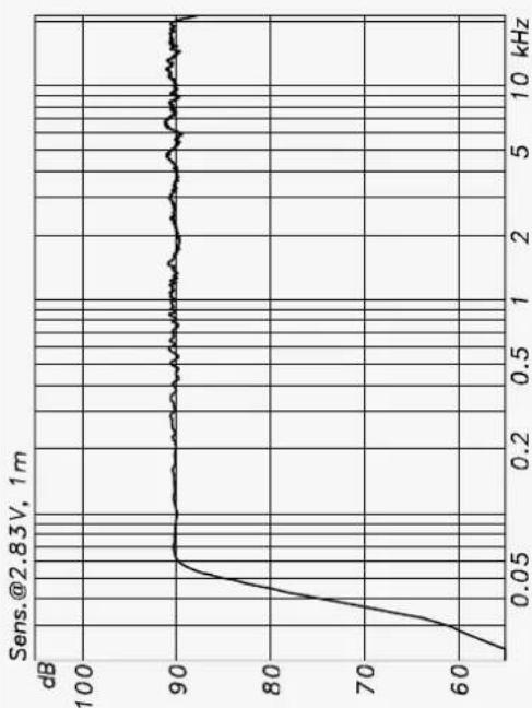
line
| Frequency (kHz) | Value (dB) | | --------------- | ---------- | | 0.0 | 60 | | 0.05 | 90 | | 0.2 | 90 | | 0.5 | 90 | | 1 | 90 | | 2 | 90 | | 5 | 90 | | 10 | 90 |Harmonic Distortion at 90 dB SPL | Klirrfaktor bei 90 dB SPL | Maximum SPL at 1 m (1% and 3%) | Maximaler SPL bei 1 m (1% und 3%) |
Distorsión harmonique à 90 dB SPL | Distorsión armónica total a 90 dB SPL | Niveau SPL maximal, à 1 m (1% et 3%) | SPL máximo a 1 m (1% y 3%)
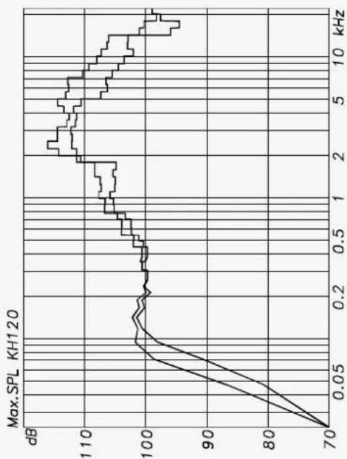
line
| Frequency (kHz) | Max SPL (dB) | | --------------- | ------------ | | 0.0 | 70 | | 0.5 | 100 | | 1.0 | 105 | | 2.0 | 110 | | 5.0 | 108 | | 10.0 | 95 |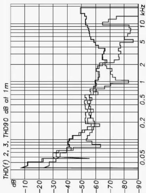
line
| Frequency (kHz) | THD(f) (dB) | | --------------- | ----------- | | 0.0 | -10 | | 0.05 | -30 | | 0.1 | -40 | | 0.2 | -50 | | 0.5 | -60 | | 1 | -70 | | 2 | -65 | | 5 | -80 | | 10 | -50 |Acoustical Controls | Akustikregler | Effet des correcteurs de compensation acoustiques | Regulador acústico
Cumulative Spectral Decay | Zerfalls spektrum | Décroissance spectrale cumulée
Caída espectral acumulada
line
| Frequency (kHz) | Freq. Resp. (dB) | | --------------- | ---------------- | | 0.0 | 60 | | 0.05 | 80 | | 0.2 | 85 | | 0.5 | 90 | | 1 | 90 | | 2 | 90 | | 5 | 90 | | 10 | 90 | | 1.5 | 85 | | 2.0 | 80 | | 5.0 | 80 | | 10.0 | 80 |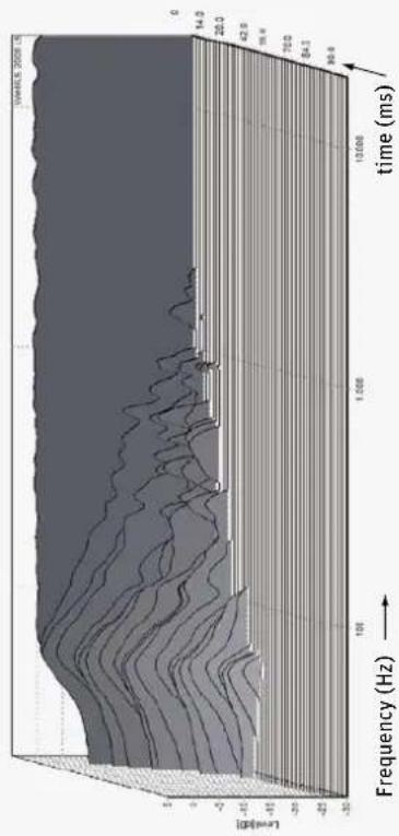
area
| Frequency (Hz) | Level (dB) | | -------------- | ---------- | | 0 | -15 | | 10 | -10 | | 100 | -5 | | 1000 | 0 | | 10000 | 5 | | 100000 | 10 |Horizontal Directivity Plot | Horizontales Abstrahlverhalten
Directivité horizontale | Directividad horizontal
Vertical Directivity Plot | Vertikales Abstrahlverhalten | Directivité verticale
Directividad vertical
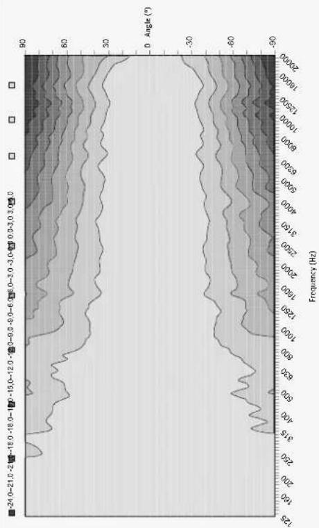
line
| Frequency (Hz) | Angle (°) | | -------------- | --------- | | 125 | -90 | | 160 | -60 | | 200 | -30 | | 250 | 0 | | 315 | 30 | | 400 | 60 | | 500 | 90 | | 630 | 60 | | 800 | 30 | | 1000 | 0 | | 1250 | -30 | | 1500 | -60 | | 2000 | -90 | | 2500 | -60 | | 3150 | -30 | | 4000 | 0 | | 5000 | 30 | | 6300 | 60 | | 8000 | 90 | | 10000 | 60 | | 12500 | 30 | | 18000 | 0 | | 20000 | -30 |Installation angles/Aufstellwinkel/Angles d'installation/Ángulos de colocación
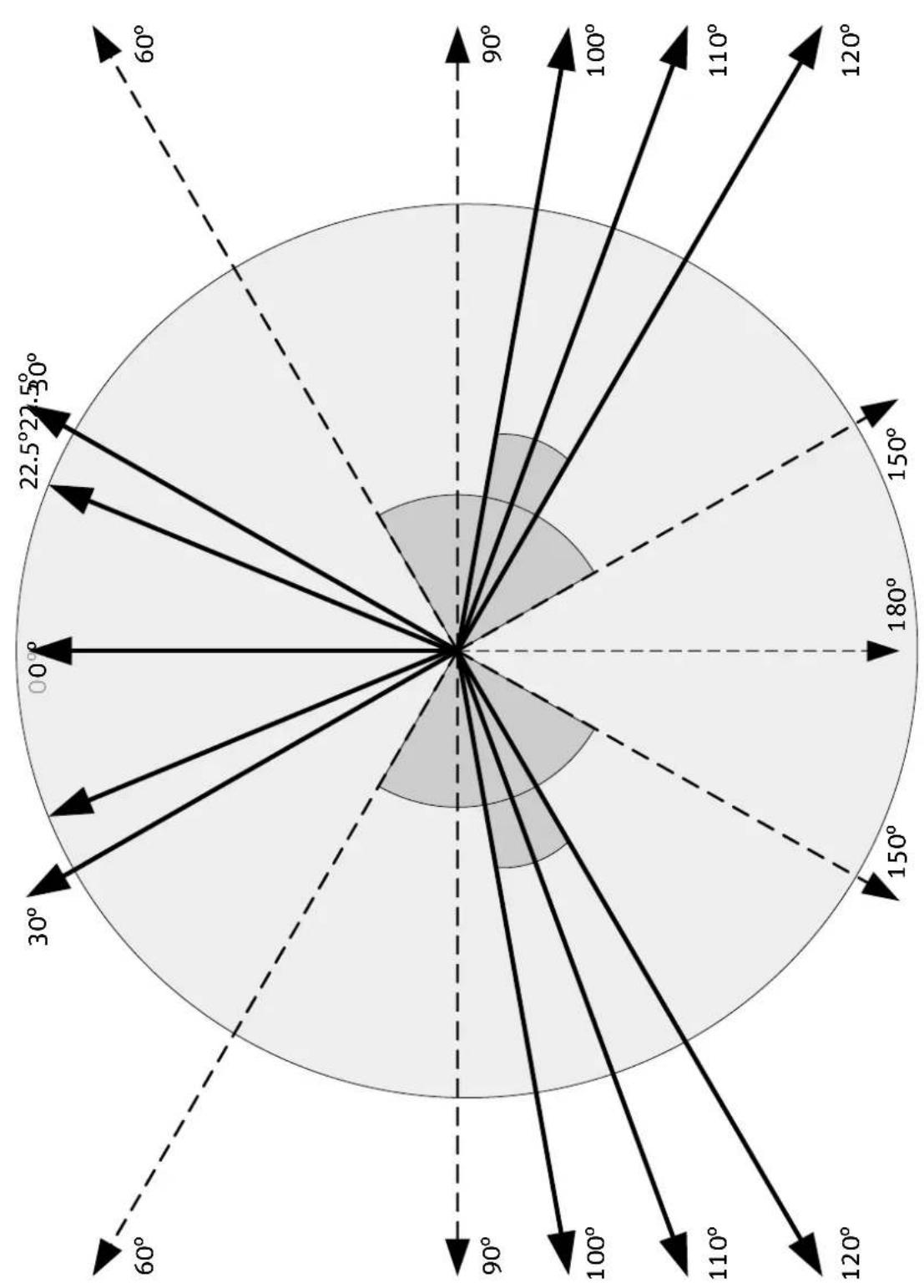
radar
| Angle | Value | |-------|-------| | 0° | 22.5° | | 30° | 25.5° | | 60° | 150° | | 90° | 180° | | 120° | 120° | | 150° | 150° | | 180° | 180° | | 210° | 150° | | 240° | 120° | | 270° | 90° | | 300° | 60° |EN
DE
FR
ES
Delay Lookup Table/Wertetabelle Delay/Tableaux de valeurs Delay/Tabla de valores Delay
Switch 1 (25.6 ms) Switch 2 (1.6 ms)
| Posi-tion | Time [ms] | Distance [m] | Distance [Imperial] | Frames | Time [ms] | Distance [m] | Distance [Imperial] | Frames | ||||
| [feet] [inches] 50 Hz | 60 Hz [feet] [inches] | 50 Hz 60 Hz | ||||||||||
| 0 | 0.0 | 0.000 | 0 | 0 | 0.0 | 0.0 | 0.0 | 0.000 | 0 | 0 | 0.0 | 0.0 |
| 1 | 25.6 | 8.806 | 28 | 11 | 0.6 | 0.8 | 1.6 | 0.550 | 1 | 10 | 0.0 | 0.0 |
| 2 | 51.2 | 17.613 | 57 | 9 | 1.3 | 1.5 | 3.2 | 1.101 | 3 | 7 | 0.1 | 0.1 |
| 3 | 76.8 | 26.419 | 86 | 8 | 1.9 | 2.3 | 4.8 | 1.651 | 5 | 5 | 0.1 | 0.1 |
| 4 | 102.4 | 35.226 | 115 | 7 | 2.6 | 3.1 | 6.4 | 2.202 | 7 | 3 | 0.2 | 0.2 |
| 5 | 128.0 | 44.032 | 144 | 6 | 3.2 | 3.8 | 8.0 | 2.752 | 9 | 0 | 0.2 | 0.2 |
| 6 | 153.6 | 52.838 | 173 | 4 | 3.8 | 4.6 | 9.6 | 3.302 | 10 | 10 | 0.2 | 0.3 |
| 7 | 179.2 | 61.645 | 202 | 3 | 4.5 | 5.4 | 11.2 | 3.853 | 12 | 8 | 0.3 | 0.3 |
| 8 | 204.8 | 70.451 | 231 | 2 | 5.1 | 6.1 | 12.8 | 4.403 | 14 | 5 | 0.3 | 0.4 |
| 9 | 230.4 | 79.258 | 260 | 0 | 5.8 | 6.9 | 14.4 | 4.954 | 16 | 3 | 0.4 | 0.4 |
| 10 | 256.0 | 88.064 | 288 | 11 | 6.4 | 7.7 | 16.0 | 5.504 | 18 | 1 | 0.4 | 0.5 |
| 11 | 281.6 | 96.870 | 317 | 10 | 7.0 | 8.4 | 17.6 | 6.054 | 19 | 10 | 0.4 | 0.5 |
| 12 | 307.2 | 105.677 | 346 | 9 | 7.7 | 9.2 | 19.2 | 6.605 | 21 | 8 | 0.5 | 0.6 |
| 13 | 332.8 | 114.483 | 375 | 7 | 8.3 | 10.0 | 20.8 | 7.155 | 23 | 6 | 0.5 | 0.6 |
| 14 | 358.4 | 123.290 | 404 | 6 | 9.0 | 10.8 | 22.4 | 7.706 | 25 | 3 | 0.6 | 0.7 |
| 15 | 384.0 | 132.096 | 433 | 5 | 9.6 | 11.5 | 24.0 | 8.256 | 27 | 1 | 0.6 | 0.7 |
Delay Lookup Table/Wertetabelle Delay/Tableaux de valeurs Delay/Tabla de valores Delay
Switch 3 (0.1 ms)
| Posi-tion | Time [ms] | Distance [m] | Distance [Imperial] Frames | |||
| [feet] [inches] 50 Hz | 60 Hz | |||||
| 0 0.0 | 0.000 0 0 | 0.0 0.0 | ||||
| 1 | 0.1 | 0.034 | 0 | 1 | 0.0 | 0.0 |
| 2 | 0.2 | 0.069 | 0 | 3 | 0.0 | 0.0 |
| 3 | 0.3 | 0.103 | 0 | 4 | 0.0 | 0.0 |
| 4 0.4 | 0.138 0 5 | 0.0 0.0 | ||||
| 5 | 0.5 | 0.172 | 0 | 7 | 0.0 | 0.0 |
| 6 | 0.6 | 0.206 | 0 | 8 | 0.0 | 0.0 |
| 7 | 0.7 | 0.241 | 0 | 9 | 0.0 | 0.0 |
| 8 | 0.8 | 0.275 | 0 | 11 | 0.0 | 0.0 |
| 9 | 0.9 | 0.310 | 1 | 0 | 0.0 | 0.0 |
| 10 | 1.0 | 0.344 | 1 | 2 | 0.0 | 0.0 |
| 11 | 1.1 | 0.378 | 1 | 3 | 0.0 | 0.0 |
| 12 | 1.2 | 0.413 | 1 | 4 | 0.0 | 0.0 |
| 13 | 1.3 | 0.447 | 1 | 6 | 0.0 | 0.0 |
| 14 | 1.4 | 0.482 | 1 | 7 | 0.0 | 0.0 |
| 15 | 1.5 | 0.516 | 1 | 8 | 0.0 | 0.0 |
EN
DE
FR
ES
- Contents
- Appendix
- Important safety instructions
- Danger due to high sound pressure levels
- WARNING
- Danger of hearing damage due to sudden high sound pressure levels!
- Magnetic fields
- Interference due to magnetic fields!
- Hazard warnings on the rear of the product
- CAUTION
- Intended use
- The KH 120 studio monitor
- Delivery includes
- Product overview
- Installing and connecting the KH 120
- Preparing the loudspeakers
- Preparing the room
- Distances
- Positioning the loudspeakers
- Connecting audio signals
- Connecting analog signals to the KH 120 A and the KH 120 D
- Connecting AES cables
- Connecting digital signals to the KH 120 D
- Wiring Pin Signal
- Connecting multiple KH 120 D loudspeakers together
- Setting the SIGNAL SELECT rotary switch ⑭
- Connecting/disconnecting the KH 120 to/from the mains power supply
- Configuring and using the KH 120
- Switching the KH 120 on/off
- Adjusting the frequency response
- Adjusting the acoustic level
- Compensating for video delay (lip sync)
- Compensating for listening distance differences (time-of-flight)
- Example
- Example:
- Activating ground lift
- Adjusting the brightness of the Neumann logo
- Danger of hearing damage due to unexpected high sound pressure levels!
- Cleaning and maintaining the KH 120
- Damage to the product caused by liquids!
- Troubleshooting
- Temperature
- Relative humidity
- Acoustical measurements, block diagram and pin assignment
- Accessories
- Product Description
- System Block Diagram/System-Blockdiagramm/Synoptique Système/Diagrama de Bloques del Sistema
- Pin assignment of the XLR socket/Buchsenbelegung XLR/Brochage de la prise XLR/Asignación de la hembra XLR
- Acoustical Measurements/Akustische Messungen/Mesures acoustiques/Mediciones Acústicas
Brand : NEUMANN
Model : KH 120 D
Category : Loudspeaker