
GL (2009) - Automotive Mercedes-Benz - Free user manual and instructions
Find the device manual for free GL (2009) Mercedes-Benz in PDF.


User questions about GL (2009) Mercedes-Benz
0 question about this device. Answer the ones you know or ask your own.
Ask a new question about this device
Download the instructions for your Automotive in PDF format for free! Find your manual GL (2009) - Mercedes-Benz and take your electronic device back in hand. On this page are published all the documents necessary for the use of your device. GL (2009) by Mercedes-Benz.
USER MANUAL GL (2009) Mercedes-Benz
text_image
Mercedes-BenzGL
Operator's Manual
Symbols
Trademarks®:
- AdBlue® is a registered trademark of the German Association of the Automotive Industry (VDA).
- BabySmart™ is a trademark of Siemens Automotive Corp.
- Bluetooth® is a registered trademark of Bluetooth SIG Inc.
- ESP® and PRE-SAFE® are registered trademarks of Daimler.
- HomeLink ^ is a registered trademark of Prince, a Johnson Controls Company.
The following symbols are found in this Operator's Manual:

Warning!
Warning notices draw your attention to hazards that may endanger your health or life, or the health or life of others.
! Highlights hazards that may result in damage to your vehicle.
i Helpful hints or further information you may find useful.
This symbol points to instructions for you to follow.
A number of these symbols appearing in succession indicates a multiple-step procedure.
▷ page This symbol tells you where to look for further information on a topic.
This continuation symbol marks a warning or procedure which is continued on the next page.
Display Text in displays, such as the control system, are printed in the type shown here.
Our company and staff congratulate you on the purchase of your new Mercedes-Benz.
Your selection of our product is a demonstration of your trust in our company name. Furthermore, it exemplifies your desire to own an automobile that will be as easy as possible to operate and provide years of service.
Your Mercedes-Benz represents the efforts of many skilled engineers and craftsmen. To help assure your driving pleasure, and also the safety of you and your passengers, we ask you to make a small investment of time:
- Please read this manual carefully, then return it to your vehicle where it will be handy for your reference.
- Please follow the recommendations contained in this manual. They are designed to acquaint you with the operation of your Mercedes-Benz.
- Please pay attention to the warnings and cautions contained in this manual. They are designed to help improve the safety of the vehicle operator and occupants.
We extend our best wishes for many miles of safe, pleasurable driving.
Safety and security 45
Controls in detail 83
Operation 263
Practical hints 325
Technical data 419
Index
1, 2, 3 ...
115V AC Socket 249
3-zone automatic climate control
see Climate control system
4-ETS (Electronic Traction System) .. 78
4MATIC
see All-wheel drive (4MATIC)
A
ABS (Antilock Brake System) ..... 76
Indicator lamp 371
Messages in the multifunction display 332, 347
Accessory weight 293
Accidents 132
Active head restraints ..... 66
Air bag deployment ..... 47
Distance warning function ..... 181
Emergency calls (Tele Aid) ..... 252
Active Bi-Xenon headlamps
Messages in the multifunction display 363
see Headlamps
Active head restraints 66
Resetting 385
Adaptive Damping System
see ADS
AdBlue ^® 405, 437
Capacity, AdBlue ^® tank ..... 433
Refilling 405
Additives
Engine oil 435
Gasoline 437
Address change 22
ADS (Adaptive Damping System) ... 185
Air bags 47
Children 47
Emergency call upon deployment . 252
Front, driver 50
Front, passenger 50
Front passenger front air bag off indicator lamp 40, 41, 56, 381, 382
Knee bag 51
Messages in the multifunction display 335
Safety guidelines 49
Side impact 51
Window curtain 52
Air conditioning refrigerant and
lubricant 435
Air distribution 207, 220
Air filter 362
Air pressure
see Tire inflation pressure
Air pressure (tires) 293
Air recirculation mode ..... 208, 222
Air suspension program ..... 185
Comfortable driving style ..... 185
Messages in the multifunction display 349
Sporty driving style ..... 185
Suspension tuning....185
Vehicle level control 186
Air volume 207, 221
Alarm system
see Anti-theft systems
Alignment bolt (vehicle tool kit)
326,401
All-wheel drive (4MATIC) ..... 193
Alternator 429
Messages in the multifunction display 360
Anticorrosion/antifreeze 439
Antiglare, Interior rear view mirror . 111
Antilock Brake System see ABS
Anti-theft systems 80
Anti-theft alarm system ..... 81
Immobilizer 80
Aquaplaning
see Hydroplaning
Ashtrays 247
Aspect ratio (tires) 294
Audio/DVD menu 153
Auto-dimming rear view mirrors . . . 112
Automatic central locking ..... 89, 163
Index
Automatic headlamp mode ..... 115
Automatic interior lighting control. 120
Automatic locking when driving ... 163
Automatic transmission ..... 135
Emergency operation (limp-home
mode)....141
Gear range indicator ..... 139
Gear ranges 139
Gear selector lever 135
Gearshifting malfunctions ..... 141
Hill start assist system ..... 181
Kickdown 139
One-touch gearshifting ..... 140
Shifting procedure ..... 137
Steering wheel gearshift control . . 140
Towing a trailer 139
Transmission position indicator . . . 137
Transmission positions ..... 137
AUX socket 242
Axle oils 432
B
BabySmart™
Air bag deactivation system ..... 57
Self-test 59
Backrest
see Seats
Backup lamps
Messages in the multifunction
display 363
Replacing bulbs 388
Bar (air pressure unit) 294
BAS (Brake Assist System) ..... 77
Batteries, SmartKey
Checking condition 88
Replacing 386
Battery, Vehicle
Charging 409
Jump starting 410
Messages in the multifunction display 360
Bead (tire) 294
Beverage holders
see Cup holders
Bleeding the fuel system (diesel
engine) 404
BlueTEC
AdBlue® tank 405, 433
Brake fluid
Messages in the multifunction
display 347
Brake lamps
Cleaning lenses 321
High-mounted brake lamp ..... 388
Replacing bulbs 388
Brake pads
Messages in the multifunction display 346
Brakes 300
Parking brake 133, 302
Warning lamp 372
Break-in period 264
Bulbs
see Replacing bulbs
C
CAC (Customer Assistance Center) .. 24
California retail buyers and
lessees, important notice for ..... 21
Calls (phone) 167
Can holders
see Cup holders
Capacities and recommended
fuel/lubricants 432
Cargo compartment
Cargo net 240
Cargo volume, expanding ..... 235
Fuse box 417
Tie-down rings 234
Cargo compartment cover blind . . . 239
Carpets, cleaning 323
Carriers 228
Index
Center console
Lower part 42
Upper part 40
Central locking
Automatic 89,163
Locking/unlocking from inside . . . . 89
Central locking/unlocking switch ... 89
Certification label 421
Children in the vehicle 68
Air bags 47
BabySmart™ air bag deactivation system 57
Blocking of rear window operation .. 74
Child safety locks (rear doors) ..... 73
Indicator lamp, front passenger front air bag 56
Infant and child restraint systems . . 68
LATCH-type child seat anchors . . . . 72
Occupant Classification System (OCS) 53
Safety notes 68
Tether anchorage points ..... 71
Child safety
see Children in the vehicle
Chrome-plated exhaust tip,
cleaning 324
Cigarette lighter 248
Climate control system
3-zone automatic climate control . 210
Air conditioning, cooling . . . . 206, 217
Air conditioning refrigerant ..... 435
Air distribution 207, 220
Air recirculation mode ..... 208, 222
Air volume 207, 221
Automatic mode ..... 206, 218
Climate control 202
Deactivating system ..... 205, 217
Front defroster ..... 207, 221
Residual engine heat (REST) . 209, 223
Temperature 207, 219
Clock 33,160
Cockpit 30
Cold tire inflation pressure ..... 294
Collapsible wheel chock ..... 326
COMAND system
see separate COMAND system operating instructions
Combination switch ..... 117
Comfort submenu
Easy-entry/exit feature ..... 163
Fold-in function for exterior rear view mirrors 164
Compass
Calling up 260
Control system 148
Multifunction display ..... 150
Multifunction steering wheel ..... 148
Resetting to factory settings ..... 157
Control system menus ..... 151
Audio/DVD 153
Distronic 156
Navigation 155
Off-road 155
Settings 157
Standard display 152
Telephone 167
Trip computer 165
Vehicle configuration ..... 164
Vehicle status message memory .. 156
Control system submenus ..... 151
Comfort 163
Instrument cluster 158
Lighting 160
Time/Date 160
Vehicle 163
Coolant
Anticorrosion/antifreeze ..... 439
Capacities 433
Checking level 271
Messages in the multifunction display .... 356, 357, 359
Corner-illuminating front fog lamps 119
Cruise control 169
Last stored speed ..... 171
Resume function ..... 171
Cup holders 245
Curb weight 294
Customer Assistance Center
see CAC
Index
D
Dashboard
see Instrument cluster
Data recording 25
Date, Setting 160
Daytime running lamp mode .. 116, 161
Deep water
see Standing water
Defroster
Rear window 223
Windshield 207, 221
Delayed shut-off
Exterior lamps 162
Interior lighting 162
Department of Transportation
see DOT
Diesel engine
preglow indicator lamp 35
Diesel fuel
see Fuel
Differential locks 144
A few words about .... 144
Messages in the multifunction
display 146,351
Switching....145
Difficulties
While driving 132
With starting 130
Digital clock
see Clock
Digital speedometer 153
Dimensions (vehicle) 430
Direction of rotation (tires) ..... 275
Displays
Digital speedometer....153
Distronic 174
Maintenance service indicator .... 316
Messages in the multifunction
display 330
Multifunction display ..... 150
Outside temperature ..... 150, 159
Symbol messages 346
Text messages 332
Trip computer ..... 150, 165
Vehicle status message memory .. 156
Vehicle system settings ..... 157
Distronic 172
Cleaning system sensor ..... 321
Control system 156
Distance warning function ..... 181
Driving hints 179
Last stored speed ..... 178
Menu 175
Messages in the multifunction
display 340
Resume function 178
Sensor cover 321
Warning and indicator lamps . 174, 377
Door control panel 44
Door handles 44
Doors
Child safety locks 73
Locking/unlocking (KEYLESS-GO) .. 85
Locking/unlocking (SmartKey)....84
Locking/unlocking from outside . . . 84
Messages in the multifunction display 353
Opening from inside 88
Remote door unlock (Tele Aid) ..... 255
Unlocking (Mechanical key) ..... 384
DOT (Department of
Transportation) 294
Downhill Speed Regulation
see DSR
Drinking and driving 299
Driving
Abroad 314
Hydroplaning 302
Instructions 128, 299
In winter 298
Off-road 303
Problems 132
Safety systems 75
Systems 169
Through standing water ..... 302
With Distronic 179
Driving and parking
Safety notes 128
Index
Driving off 131, 302
Driving safety systems ..... 75
4-ETS 78
ABS 76
BAS 77
EBP 77
ESP ^® 77
Driving systems
Air suspension program ..... 185
Cruise control 169
Distronic 172
Downhill Speed Regulation (DSR) . 182
Off-road driving program ..... 185
Parktronic system 193
Rear view camera ..... 197
Driving tips, automatic
transmission 139
DSR (Downhill Speed Regulation) .. 182
Messages in the multifunction display 353
E
Easy-entry/exit feature ..... 109, 163
EBP (Electronic Brake
Proportioning)....77
Electrical system
Improper work on or modifications . 23
Power outlets 249
Technical data 429
Electronic Stability Program
see ESP®
Electronic Traction System
see 4-ETS
Emergency, in case of
Battery, jump starting ..... 410
First aid kit 326
Flat tire 397
Hazard warning flasher ..... 118
Roadside Assistance 22
Towing the vehicle 412
Emergency calls
Tele Aid 252
Emergency engine shutdown ..... 417
Emergency operations
Limp-home mode 141
Locking/unlocking the vehicle ... 384
Remote door unlock 255
Emergency Tensioning Device
see ETD
Emission control 315
Information label 422
System warranties 21
Engine
Brake-in recommendations ..... 264
Cleaning 319
Compartment 267
Malfunction indicator lamp
35, 379
Maximum engine speed ..... 423
Messages in the multifunction
display 356
Number 422
Starting 128
Technical data 423
Turning off 133
Engine coolant
see Coolant
Engine oil
Adding 270
Additives 435
Checking level 269
Consumption 269
Messages in the multifunction
display 361
Oil dipstick 269
Recommended engine oils and oil
filter 434
ESP® (Electronic Stability Program) . 77
4-ETS 78
Messages in the multifunction
display 333, 347
Off-road ESP ^® 80
Trailer stabilization 80
Warning lamp 376
ETD (Emergency Tensioning
Device) 64
Safety guidelines 49
Index
Express operation
Power windows 124
Tilt/sliding sunroof 224
Exterior lamp switch 115
Exterior rear view mirrors ..... 111
Fold-in function ..... 164
Power folding 112
Exterior view of vehicle 28
F
Fastening the seat belts 61
First aid kit 326
Flat tire 397
Lowering the vehicle ..... 402
Mounting the spare wheel ..... 398
Preparing the vehicle ..... 398
Spare wheel 398,428
Floormats 260
Fluids
AdBlue ^® 433
Automatic transmission fluid ..... 432
Brake fluid 433
Capacities 432
Engine coolant 433
Engine oil 432
Power steering fluid 433
Washer and headlamp cleaning
system 434
Fog lamps 117
Messages in the multifunction display....364, 365 Replacing bulbs....388
Fold-in function for exterior rear
view mirrors 164
Four-wheel drive see All-wheel drive (4MATIC)
Front air bags
see Air bags
Front axle oil 432
Front lamps
see Headlamps
Front passenger front air bag ..... 50 Messages in the multifunction display ..... 335
Front passenger front air bag off
indicator lamp
40, 41, 51, 381, 382
Front seat head restraints
see Head restraints
Fuel 266,299
Additives 437
Capacity, fuel tank 433
Diesel fuel 266,433
Fuel consumption statistics ..... 165
Fuel filler flap and cap ..... 265
Fuel tank reserve warning lamp 35,378
Premium unleaded gasoline
266,433,435
Refueling 265
Requirements 436
Fuel filler flap 266
Locking/unlocking 266
Opening 266
Opening manually 385
Fuels, coolants, lubricants etc.
Capacities 432
Fuel system, bleeding (diesel
engine) 404
Fuel tank
Capacity 433
Fuel filler flap and cap ..... 265
Refueling 265
Fuses 415
Fuse box in cargo compartment . . 417
G
Garage door opener 43,256
Gasoline
see Fuel
GAWR (Gross Axle Weight Rating) .. 294
Gear range
Automatic transmission ..... 139
Indicator 139
Limiting 140
Index
Shifting into optimal ..... 141
Transfer case 142
Gear selector lever 135
Cleaning 323
Gearshift pattern 135
Messages in the multifunction display 343, 344
Shifting procedure ..... 137
Transmission position indicator . . . 137
Transmission positions ..... 137
Generator
see Alternator
Global locking/unlocking
see Key, SmartKey
Glove box 242
Gross Axle Weight Rating see GAWR
Gross Trailer Weight see GTW
Gross Vehicle Weight see GVW
Gross Vehicle Weight Rating see GVWR
GTW 294
GVW (Gross Vehicle Weight) ..... 294
GVWR (Gross Vehicle Weight
Rating) 294
H
Halogen headlamps
see Headlamps
Hard plastic trim items, cleaning . . 323
Hazard warning flasher ..... 118
Headlamp cleaning system ..... 119
Headlamps
Active Bi-Xenon headlamps ..... 114
Adjusting aim 394
Automatic headlamp mode ..... 115
Bi-Xenon 114,388
Cleaning lenses 321
Cleaning system 119
Delayed shut-off....162
Halogen 389
High-beam flasher 118
High-beam headlamps ..... 118
Low-beam headlamps ..... 115
Replacing bulbs 388
Switch 115
Headliner, cleaning and care of .... 323
Head restraints 97
Active head restraints ..... 66, 385
Adjusting 99
Heated seats 107
Heated steering wheel 110
Height adjustment
Seats 98
Vehicle level control 186
High-beam flasher 118
High-beam headlamps ..... 118, 388
Indicator lamp 35
Replacing bulbs 388
High-mounted brake lamp ..... 388
Replacing bulbs 388
Hill start assist system ..... 181
Hinged quarter windows ..... 126
Hood 267
Messages in the multifunction display 353
Hooks 234
Horn 31
HVAC
see Climate control system
Hydroplaning 302
|
Identification labels ..... 421
Identification number, vehicle
(VIN) 421
Ignition 95, 97, 129
Immobilizer 80
Indicator lamps
see Lamps, indicator and warning
Infant and child restraint systems
see Children in the vehicle
Inflation pressure
see Tires, Inflation pressure
Index
see Instrument cluster, Illumination
Instrument panel
see Instrument cluster
Instruments and controls
see Cockpit
Interior lighting
Delayed shut-off 162
Emergency lighting 121
Front 120
Front reading lamps ..... 120
Rear 121
Rear reading lamps ..... 121
Interior rear view mirror ..... 111
Auto-dimming rear view mirrors . . . 112
Interior storage spaces
see Storage compartments
Intermittent wiping
Windshield wipers 122
J
Jack 329
Jump starting 410
K
Key, Mechanical 384
Loss of 88
Key, SmartKey
Battery check lamp 85
Checking batteries 88
Factory setting 85, 87
Global locking (KEYLESS-GO) 87
Global locking (SmartKey) 85
Global unlocking (KEYLESS-GO) 87
Global unlocking (SmartKey) ..... 85
Important notes on KEYLESS-GO...86
Locking/unlocking 84
Loss of 88
Messages in the multifunction display....353, 354
Opening and closing the power tilt/sliding sunroof .... 127
Opening and closing the windows . 127
Remote control 84
Replacing batteries 386
Restoring to factory setting .... 85, 87
Selective setting 85, 87
Starter switch positions ..... 95
KEYLESS-GO
Starter switch positions ..... 96
Kickdown 139
Kilopascal (air pressure unit) ..... 294
Knee bag 51
L
Labels
Certification 421
Emission control information ..... 422
Lamps, exterior
Exterior lamp switch 115
Front 388
Messages in the multifunction
display 363
Rear 388
Switching on/off 115
Lamps, indicator and warning
ABS 33,371
Battery (SmartKey) 85
Brakes 372
Center console 40
Differential locks 145
Distance warning lamp. 174, 181, 377
Engine malfunction ..... 35, 379
ESP ^® 33, 376
Fog lamps 117
Front passenger front air bag off 40, 41, 51, 381, 382
Fuel tank reserve 35, 378
High-beam headlamps ..... 35
Instrument cluster 370
Index
Seat belt telltale 35, 374
SRS 47,375
Turn signals 33
Language, selecting ..... 159
LATCH-type child seat anchors
see Children in the vehicle
License plate lamps 388
Messages in the multifunction display 365
Replacing bulbs 388
Light alloy wheels, cleaning ..... 322
Lighter
see Cigarette lighter
Lighting 114
Daytime running lamp mode ..... 116
Exterior 115
Interior 120
Limp-home mode 141
Loading
see Vehicle loading
Locator lighting 161
Lock button
Door handle (KEYLESS-GO) ..... 87
Locking the vehicle ..... 84, 85
Manually 384
Loss of
Key 88
Service and Warranty Information booklet 421
Low-beam headlamps ..... 115
Exterior lamp switch ..... 115
Replacing bulbs 388
Switching on....115
LOW RANGE mode 142
Messages in the multifunction display 352
Switching 143
Lubricants 432
Lumbar support 103
M
Maintenance 22
Maintenance System 315
Calling up service indicator ..... 317
Clearing service indicator message 316
Resetting service indicator ..... 317
Service indicator 316
Service indicator message ..... 316
Service term exceeded ..... 316
Manual headlamp mode (Low-
beam headlamps)....115
Maximum loaded vehicle weight ... 294
Maximum load rating (tires) ..... 294
Maximum permissible tire
inflation pressure 295
Mechanical key 384
Media interface 242
Memory function 113
Menus
see Control system menus
Minispare wheel
see Spare wheel
Mirrors
Auto-dimming rear view mirrors . . . 112
Exterior rear view mirrors ..... 111
Interior rear view mirror ..... 111
Memory function ..... 113
MOExtended system 403
MOExtended tires ..... 403, 425
MON (Motor Octane Number) . 266, 436
Motor Octane Number
see MON
Multicontour seats 106
Multifunction display ..... 150
Symbol messages ..... 346
Text messages 332
Vehicle status messages ..... 330
Multifunction display messages
ABS 332,347
Active headlamps 363
Air bags 335
Air filter 362
Air suspension program ..... 349
Alternator 360
Automatic transmission
343, 344
Battery 360
Index
Brake fluid 347
Brake pads 346
Coolant 356, 357, 359
Corner-illuminating front fog
lamps 366
Cruise control 340
Differential locks ..... 146, 351
Display malfunction .... 330
Distronic 340
Doors 353
Downhill Speed Regulation (DSR) . 353
EBP 347
Engine oil 361
ESP ^® 333, 347
Fog lamps 364, 365
Front passenger front air bag .... 335
Gas cap 362
Gear selector lever 343, 344
High-beam lamps 364
Hood 353
License plate lamps 365
Light sensor 365
Low-beam lamps 365
LOW RANGE mode 352
Parking brake 347
Parking lamps 364
PRE-SAFE ^® 334
Reserve fuel 362
Reverse lamp 363
Side marker lamps 364
SmartKey 354
SmartKey with KEYLESS-GO ..... 353
SRS 348
Tailgate 353
Tail lamps 366
Tele Aid 348
Tire pressure 344, 368
Tire pressure monitor 345
Tires 344, 368
TPMS 345,368
Trailer brake lamps 366
Trailer tail lamps 366
Trailer turn signal lamps ..... 367
Turn signals 367
Washer fluid 355
Multifunction steering wheel
Adjusting 108
Buttons 148
Cleaning 323
Easy-entry/exit feature ..... 109, 163
Gearshift control 140
Heating 110
Memory function 113
Overview 38
N
Navigation menu 155
Nets, parcel 233
Night security illumination ... 117, 162
Normal occupant weight ..... 295
Number, vehicle identification
(VIN) 421
0
Occupant Classification System see OCS
Occupant distribution ..... 295
Occupant safety 46
Air bags 47
BabySmart™ 57
Children and air bags 47
Children in the vehicle 68
Fastening the seat belts 61
Front passenger front air bag off indicator lamp ..... 53, 381, 382
Infant and child restraint systems . . 68
LATCH-type child seat anchors .... 72
OCS 53
PRE-SAFE ^® 65
Seat belts 49,59
OCS (Occupant Classification
System) 53
Self-test 56
Odometer 150
Off-road driving 303
Checklist 304, 309
Crossing obstacles 307
Driving instructions ..... 303
Index
Driving on sand 308
Driving through water ..... 306
Returning 309
Ruts 308
Steep terrain 305
Off-road driving program ..... 185
Off-road menu 155
Oil
see Engine oil
Oil level
see Engine oil, Checking level
On-board computer
see Control system
One-touch gearshifting ..... 140
Operating safety 23
Ornamental moldings, cleaning .... 320
Outside temperature
see Displays
Overhead control panel 43
P
Paintwork, cleaning 319
Paintwork code 421
Panic alarm 75
Panorama roof
Sunshade 247
Parcel nets 233
Parking 132
Parktronic 193
Parking brake 133, 302
Messages in the multifunction display 347
Parking position
Transmission position ..... 137
Parktronic 40, 41
Cleaning system sensors ..... 321
Malfunctions 197
Minimum distance ..... 195
Range 194
System sensors ..... 194, 321
Warning indicators ..... 31, 195
Parts service 420
PASS AIR BAG OFF indicator lamp
see Front passenger front air bag off indicator lamp
Passenger safety
see Occupant safety
Pedals 299
Phone
see Telephone
Plastic parts, cleaning ..... 323
Power assistance 300
Power outlets 249
Power seats
see Seats
Power tailgate
Closing 91
Messages in the multifunction display....353 Opening....91
Power tilt/sliding sunroof
Operation 224
Synchronizing 226
Power washer 319
Power windows 124
Cleaning .... 322
Door windows .... 125
Hinged quarter windows .... 126
Operation .... 124
Rear door window, Blocking operation .... 74
Synchronizing .... 126
Practical hints 326
Preglow indicator lamp ..... 35, 129
PRE-SAFE ^® 65 Messages in the multifunction display 334
Problems
While driving....132 With vehicle....24
Product information 20
Production options weight ..... 295
Proximity key
see Key, SmartKey
PSI (air pressure unit) 295
Index
Push-start
see Tow-start
R
Radio
Selecting stations ..... 154
Radio transmitters .... 314
Rear axle oil 432
Rear doors
Child safety locks 73
Rear door window
Blocking operation 74
Rear fog lamp
see Fog lamps
Rear lamps
see Tail lamps
Rear seats
see Seats
Rear view camera 197
cleaning the lens 321
Rear window defroster ..... 223
Rear window wiper/washer ..... 123
Recommended tire inflation
pressure 279, 295
Recovery services, Stolen vehicle
(Tele Aid) 256
Refilling
AdBlue ^® 405
Refrigerant, air conditioning ..... 435
Refueling 265
Regular checks 267
Reminder, Seat belt
see Seat belts, Telltale
Remote control
see Key, SmartKey
Remote door unlock (Tele Aid) ..... 255
Replacing bulbs 388
Brake lamps 388
Headlamps 388
High-beam headlamps ..... 388
High-mounted brake lamp ..... 388
License plate lamps 388
Low-beam headlamps ..... 388
Parking lamps 388
Side marker lamps 388
Standing lamps 388
Tail lamps 388
Turn signal lamps 388
Reporting safety defects ..... 25
Research Octane Number
see RON
Reserve fuel
Messages in the multifunction
display 362
Warning lamp 35
Reset button 33, 147, 157
Restraint systems
see Occupant safety
Rims 295,425
Roadside Assistance ..... 22, 253
RON (Research Octane Number)
266,436
Roof rack 228
Route guidance
see Navigation system
Rubber parts, cleaning 323
Run Flat Indicator 282
Run-flat tires
see MOExtended tires
S
Safety
Driving safety systems .....75
Occupant safety 46
Reporting defects 25
Safety belts
see Seat belts
Seat belt force limiter 64
Seat belts 59
Children in the vehicle ..... 68
Cleaning 323
Fastening 61
Height adjustment 63
Proper use of 60
Safety guidelines 49
Safety notes 59
Telltale 35, 374
Warning lamp 374
Index
Seating capacity 276
Seats 97
Adjusting 98
Easy-entry/exit feature ..... 109
Folding (expanding cargo volume) . 235
Heating....107
Memory function 113
Multicontour seat 106
Rear seats 103
Ventilation 107
Securing cargo Cargo tie-down rings ..... 234
Selective setting see Key, SmartKey
Selector lever see Gear selector lever
Self-test BabySmart™....59 OCS....56 Tele Aid....252
Service see Maintenance
Service, parts 420
Service and warranty information . . . 21
Service intervals see Maintenance System, Service indicator
Service life (tires) 274
Settings
Control system menus and submenus....151 Date....160 Factory setting (SmartKey)....85, 87 Individual (vehicle)....157 Memory function....113 Menu....157 Selective setting (SmartKey)....85, 87 Time....160
Side impact air bags 51
Side marker lamps Cleaning lenses .... 321 Messages in the multifunction display .... 364 Replacing bulbs .... 388
Sidewall (tires) 295
Side windows see Power windows
SmartKey see Key, SmartKey
SmartKey with KEYLESS-GO see Key, SmartKey
Snow chains 297
Snow tires see Winter tires
Spare wheel....329, 425 Mounting....398
Speedometer 33, 174
Speed settings Distronic....176 Resume function....178
Sport Utility Vehicle see SUV
SRS 47 Indicator lamp 35, 375 Messages in the multifunction display 348
Standing water, driving through . . . 302 Starter switch positions ..... 95, 96 Starting difficulties (engine) ..... 130 Starting the engine ..... 128
Steering column see Multifunction steering wheel, Adjusting
Steering wheel see Multifunction steering wheel
Steering wheel gearshift control ... 140
Stolen Vehicle Recovery services .. 256
Storage compartments ..... 36, 242
Storing tires 274
Stranded vehicle 414
Submenus see Control system submenus
Sunroof see Power tilt/sliding sunroof
Sunshade Rear panorama roof ..... 247
Sunvisors 246
Index
Suspension tuning
see Air suspension program
SUV (Sport Utility Vehicle) ..... 23
T
Tachometer 35, 148
Overspeed range 148
Tailgate
Closing 90
Messages in the multifunction
display 353
Opening 90
Power tailgate 91
Tail lamps 388
Cleaning lenses 321
Messages in the multifunction
display 366
Replacing bulbs 388
Tar stains 319
Technical data
Air conditioning refrigerant ..... 435
Brake fluid 435
Capacities fuels, coolants,
lubricants etc. 432
Coolant 438
Dimensions 430
Electrical system 429
Engine 423
Engine oil additives ..... 435
Engine oils 434
Fuel requirements ..... 436
Gasoline additives ..... 437
Identification labels ..... 421
Premium unleaded gasoline ..... 435
Rims and tires 425
Spare wheel 428
Washer and headlamp cleaning
system 434
Weights 431
Tele Aid 251
Emergency calls 252
Information button 254
Initiating an emergency call
manually 253
Messages in the multifunction
display 348
Remote door unlock 255
Roadside Assistance button ..... 253
SOS button 253
Stolen Vehicle Recovery services . 256
System self-test 252
Telephone 38
Answering/ending a call ..... 167
Hands-free microphone ..... 43
Menu 167
Operation 167
Phone book 167
Redialing 168
Temperature
Interior temperature ..... 207, 219
Outside 153, 159
Tether anchorage points
see Children in the vehicle
Tie-down rings 234
Tightening torque
Spark plugs 429
Wheels 403
Time setting 160
TIN (Tire Identification Number) ... 295
Tire and Loading Information
Placard 275
Tire and loading terminology ..... 293
Tire Identification Number
see TIN
Tire inflation pressure
Checking 281
Important notes on 280
Placard on driver's door B-pillar . . . 275
Tire labeling 286
Tire load rating 295
Tire ply composition and material
used 295
Tire Pressure Monitoring System
(TPMS) 283
Messages in the multifunction display 345, 368
Tires 272,425
Air pressure 279
Index
Care and maintenance ..... 273
Cleaning 274
Direction of rotation, spinning .... 275
Important notes on tire inflation pressure 280
Inflation pressure ..... 280, 281
Information placard ..... 275
Inspection 273
Labeling 286
Load rating 295
Messages in the multifunction display 344, 368
MOExtended 425
Ply composition and material used 295
Problems under-/overinflation . . . . 280
Retreads 272
Rims and tires (technical data) ... 425
Rotation 296
Run Flat Indicator 282
Service life 274
Sizes 425
Snow chains 297
Speed rating 288, 295
Storing 274
Temperature 280, 293
Terminology 293
Tire Identification Number ..... 295
Tire Pressure Monitoring System (TPMS) 283
TPMS low tire pressure/ malfunction telltale ..... 380
Traction 292, 296
Tread 296
Tread depth 274, 297
Treadwear indicators ..... 274, 296
Vehicle maximum load on ..... 296
Wear pattern 296
Winter tires 297,425
Tire speed rating 288, 295
Tongue Weight Rating see TWR
Top tether Children in the vehicle ..... 68
Total load limit 295
Towing Trailer....139 Vehicle....412
Towing eye bolt 413
Tow-start 410, 412
Traction 296
Trailer towing 139, 310 Coupling a trailer 311
Decoupling 313
Electrical connections ..... 310
Towing 312
Trailer hitch 310
Weights and ratings 310
Transfer case 141 Gear ranges 142
LOW RANGE mode ..... 142
Switching LOW RANGE mode .... 143
Transmission see Automatic transmission Transmission fluid level ..... 270
Transmission gear selector lever see Gear selector lever
Transmission positions ..... 137
Traveling abroad 314
Tread (tires) 296
Tread depth (tires) ..... 274, 297
Treadwear indicators (tires) ... 274, 296
Trip computer menu ..... 165
Trip odometer, resetting ..... 148
Turning off the engine 133
Turn signals 118 Additional in mirrors 388
Bulbs 388
Cleaning lenses 321
Indicator lamps 33
Messages in the multifunction display 367
Replacing bulbs 388
TWR (Tongue Weight Rating) ..... 296
Index
U
Uniform Tire Quality Grading
Standards 292, 296
Units, Settings
Speedometer 159
Unleaded gasoline, premium ..... 435
Unlocking the vehicle ..... 84, 85
Manually 384
Upholstery, cleaning 323
Useful features 245
V
Vehicle
Battery 408
Care 318
Control system 148
Dimensions 430
Individual settings ..... 157
Locking/unlocking 84, 85
Locking/unlocking manually ..... 384
Lowering (wheel change) ..... 402
Modifications and alterations,
Operating safety 23
Towing 412
Vehicle configuration menu ..... 164
Vehicle jack
see Jack
Vehicle level control
see Air suspension program
Vehicle lighting 114
Vehicle loading
Cargo tie-down rings ..... 234
Carrier 228
Instructions 227
Load limit 277
Terminology 293
Vehicle maximum load on the tire .. 296
Vehicle Recovery services, Stolen
(Tele Aid) 256
Vehicle status message memory ... 156
Vehicle tool kit 326
Vehicle washing
see Vehicle care
W
Warning lamps
see Lamps, Indicator and warning
Warning sounds
Distance warning function ..... 181
Distronic 174
Driver's or passenger's seat belt . . . 64
Parking brake 347
Parktronic system 197
Seat belt telltale 374
Warranty coverage 420
Washer fluid
Messages in the multifunction
display 355
Mixing ratio 440
Refilling 271
Wiping 123
Washer system 440
Washing the vehicle 318
Wear pattern (tires) 296
Wheel
Changing 398
Removing 401
Spare 398
Tightening torque 403
Wheels, sizes 425
Wheels, Tires and 272
Window curtain air bags ..... 52
Windows
see Power windows
Windows, cleaning 322
Windshield
Cleaning wiper blades ..... 322
Washer fluid 123,440
Wipers 122
Windshield wipers
Replacing wiper blades ..... 395
Winter driving
Snow chains 297
Tires 297
Winter driving instructions ..... 298
Index
Winter tires 297,425
Wood trims, cleaning ..... 324
Introduction
Operator's Manual
Product Information
Please observe the following in your own best interest:
We recommend using Genuine Mercedes-Benz Parts as well as conversion parts and accessories explicitly approved by us for your vehicle model.
We have tested these parts to determine their reliability, safety and special suitability for Mercedes-Benz vehicles.
We are unable to make an assessment for other products and therefore cannot be held responsible for them, even if in individual cases an official approval or authorization by governmental or other agencies should exist. Use of such parts and accessories could adversely affect the safety, performance or reliability of your vehicle. Please do not use them.
Genuine Mercedes-Benz Parts and pre-approved conversion parts and accessories are available at any authorized Mercedes-Benz Center. In addition, you will receive comprehensive information on permissible technical modifications and expert installations.
Operator's Manual
Notes
This Operator's Manual contains a great deal of useful information. We urge you to read it carefully and familiarize yourself with the vehicle before driving.
For your own safety and longer service life of the vehicle, we urge you to follow the instructions and warnings contained in this Operator's Manual. Ignoring them could result in damage to the vehicle or personal injury to you or others. Vehicle damage caused by failure to follow instructions is not covered by the Mercedes-Benz Limited Warranty.
We continuously strive to improve our product, and ask for your understanding that we reserve the right to make changes in design and equipment. Therefore, information, illustrations and descriptions in this Operator's Manual might differ from your vehicle.
Vehicle equipment
Your vehicle may have some or all of the equipment described in this manual.
Therefore, you may find explanations for optional equipment not installed in your vehicle. If you have any questions about operating any equipment, any authorized Mercedes-Benz Center will be glad to demonstrate the proper procedures.
Optional equipment is also described in this manual, including operating instructions wherever necessary. Since they are special-order items, the descriptions and illustrations herein may vary slightly from the actual equipment of your vehicle.
If there are any equipment details that are not shown or described in this Operator's Manual, any authorized Mercedes-Benz Center will be glad to inform you of correct care and operating procedures. The Operator's Manual and Maintenance Booklet are important documents and should be kept with the vehicle.
Introduction
Operator's Manual
Service and warranty information
The Service and Warranty Information booklet contains detailed information about the warranties covering your Mercedes-Benz, including:
- New Truck Limited Warranty
- Emission System Warranty
- Emission Performance Warranty
- California, Connecticut, Maine, Massachusetts, New York, Pennsylvania, Rhode Island, and Vermont Emission Control System Warranty ^1
- State Warranty Enforcement Laws (Lemon Laws)
Important notice for California retail buyers and lessees of Mercedes-Benz automobiles
Under California law you may be entitled to a replacement of your vehicle or a refund of the purchase price or lease price, if after a reasonable number of repair attempts Mercedes-Benz USA, LLC and/or its authorized repair or service facilities fail to fix one or more substantial defects or malfunctions in the vehicle that are covered by its express warranty. During the period of 18 months from original delivery of the vehicle or the accumulation of 18 000 miles (approximately 29 000 km) on the odometer of the vehicle, whichever occurs first, a reasonable number of repair attempts is presumed for a retail buyer or lessee if one or more of the following occurs:
(1) the same substantial defect or malfunction results in a condition that is likely to cause death or serious bodily injury if the vehicle is driven, that defect or malfunction has been subject to repair two or more times, and you have directly
notified Mercedes-Benz USA, LLC in writing of the need for its repair,
(2) the same substantial defect or malfunction of a less serious nature than category (1) has been subject to repair four or more times and you have directly notified us in writing of the need for its repair, or
(3) the vehicle is out of service by reason of repair of the same or different substantial defects or malfunctions for a cumulative total of more than 30 calendar days.
Written notification should not be sent to a dealer, it should be addressed to
Customer Assistance Center
One Mercedes Drive
Montvale, NJ 07645-0350
Introduction
Operator's Manual
Maintenance
The Maintenance Booklet describes all the necessary maintenance work which should be performed at regular intervals.
Always have the Maintenance Booklet with you when you take the vehicle to an authorized Mercedes-Benz Center for service. The service advisor will record each service in the booklet for you.
Roadside Assistance
The Mercedes-Benz Roadside Assistance Program provides factory-trained technical help in the event of a breakdown. Calls to the toll-free Roadside Assistance number
1-800-FOR-MERCedes (in the USA) 1-800-387-0100 (in Canada)
will be answered by Mercedes-Benz Customer Assistance Representatives 24 hours a day, 365 days a year.
Roadside Assistance will be provided in accordance with standard program guidelines which include providing service to the vehicle up to a reasonable distance from a paved roadway. We will make every effort to assist in a breakdown situation, however, the accessibility of your vehicle will be
determined by our authorized Mercedes-Benz Center technician or the tow service provider on a case-by-case basis and may be a factor in our ability to respond.
Additional charges may be applicable for a breakdown location determined not to be a reasonably accessible roadside location as determined by our authorized technician and tow service provider.
For additional information refer to the Mercedes-Benz Roadside Assistance Program brochure (in the USA) or the Roadside Assistance section of the Service and Warranty Information Booklet (in Canada) in your vehicle literature portfolio.
Change of address or ownership
If you change your address, be sure to send in the “Change of Address Notice” found in the Service and Warranty Information Booklet, or simply call the Mercedes-Benz Customer Assistance Center (in the USA) at 1-800-FOR-MERCedes, or Customer Service (in Canada) at 1-800-387-0100. This will assist us in contacting you in a timely manner should the need arise.
If you sell your Mercedes, please leave all literature with the vehicle to make it available to the next operator.
If you bought this vehicle used, be sure to send in the "Notice of Purchase of Used Truck" found in the Service and Warranty Information Booklet, or call the Mercedes-Benz Customer Assistance Center (in the USA) at 1-800-FOR-MERCedes, or Customer Service (in Canada) at 1-800-387-0100.
Operating your vehicle outside the USA or Canada
If you plan to operate your vehicle in foreign countries, please be aware that:
• service facilities or replacement parts may not be readily available,
- unleaded gasoline for vehicles with catalytic converters may not be available; the use of leaded fuels will damage the catalysts,
• gasoline may have a considerably lower octane rating, and improper fuel can cause engine damage.
Sport Utility Vehicle

Warning!
This Sport Utility Vehicle is designed for both on-road and off-road use. It can go places and perform tasks for which conventional 2-wheel drive passenger cars are not intended. This vehicle will handle and maneuver differently from conventional passenger cars in driving conditions which may occur on streets, highways and off-road use.
This vehicle has a higher ground clearance and a higher center of gravity than many passenger cars. As with other vehicles of this type, if you make sharp turns at excessive speeds or abrupt maneuvers, the vehicle may roll over or may go out of control and crash. Utility vehicles have a significantly higher rollover rate than other types of vehicles. Failure to operate this vehicle safely may result in an accident, rollover of the vehicle, and severe or fatal injury.
Before you start to drive this vehicle, read the Operator's Manual. Take time to become familiar with the driving characteristics of this vehicle. Be sure you are familiar with all vehicle controls. Learn
how your vehicle handles on different road surfaces. Do not attempt sharp turns at excessive speeds or abrupt maneuvers or other unsafe driving actions that can cause loss of vehicle control. When driving off-road or working the vehicle hard, do not overload it. And, always wear your seat belts at all times. In a rollover crash, an unbelted person is significantly more likely to die than a person wearing a seat belt.
Operating safety

Warning!
Work improperly carried out on electronic components and associated software could cause them to cease functioning. Because the vehicle's electronic components are interconnected, any modifications made may produce an undesired effect on other systems. Electronic malfunctions could seriously impair the operating safety of your vehicle.
Contact an authorized Mercedes-Benz Center for repairs or modifications to electronic components.
Other improper work or modifications on the vehicle could also have a negative impact on the operating safety of the vehicle.
Some safety systems only function while the engine is running. You should therefore never turn off the engine while driving.

Warning!
Heavy blows against the vehicle underbody or tires/wheels, for example when running over an obstacle, road debris or a pothole, may cause serious damage and impair the
Introduction
Problems with your vehicle
operating safety of your vehicle. If you feel a sudden significant vibration or ride disturbance, or you suspect that damage to your vehicle has occurred, you should turn on your hazard warning flashers, carefully slow down, and drive with caution to an area which is a safe distance from the road. Inspect the vehicle underbody and tires/ wheels for possible damage. If the vehicle appears unsafe, have it towed to the nearest authorized Mercedes-Benz Center or other qualified maintenance or repair facility for further inspection or repairs.
Proper use of the vehicle
Proper use of the vehicle requires that you are familiar with the following information and rules:
• the safety precautions in this manual
- the "Technical data" section in this manual
- traffic rules and regulations
• motor vehicle laws and safety standards
Warning!
Various warning labels are attached to your vehicle. These warning labels are intended
to make you and others aware of various risks. You should not remove any of these warning labels unless explicitly instructed to do so by information on the label itself. Removal of any of these labels may cause you and others to be unaware of certain risks which may result in an accident and/or personal injury.
Problems with your vehicle
If you should experience a problem with your vehicle, particularly one that you believe may affect its safe operation, we urge you to contact an authorized Mercedes-Benz Center immediately to have the problem diagnosed and corrected if required. If the matter is not handled to your satisfaction, please discuss the problem with the Mercedes-Benz Center management or, if necessary, contact us at one of the following addresses:
In the USA:
Customer Assistance Center
Customer Relations Department
Mercedes-Benz Canada, Inc.
98 Vanderhoof Avenue
Toronto, Ontario M4G 4C9
Introduction
Vehicle data recording
Reporting safety defects
For the USA only:
The following text is published as required of manufacturers under Title 49, Code of U.S. Federal Regulations, Part 575 pursuant to the "National Traffic and Motor Vehicle Safety Act of 1966".
Reporting safety defects
If you believe that your vehicle has a defect which could cause a crash or could cause injury or death, you should immediately inform the National Highway Traffic Safety Administration (NHTSA) in addition to notifying Mercedes-Benz USA, LLC.
If NHTSA receives similar complaints, it may open an investigation, and if it finds that a safety defect exists in a group of vehicles, it may order a recall and remedy campaign. However, NHTSA cannot become involved in individual problems between you, your dealer, or Mercedes-Benz USA, LLC.
To contact NHTSA, you may call the Vehicle Safety Hotline toll-free at 1-888-327-4236 (TTY: 1-800-424-9153); go to www.safercar.gov; or write to: Administrator, NHTSA Headquarters,
1200 New Jersey Avenue, SE, West Building, Washington, DC 20590.
You can also obtain other information about motor vehicle safety from www.safercar.gov.
Vehicle data recording
Information regarding electronic recording devices
(Including notice pursuant to California Code § 9951)
Please note that your vehicle is equipped with devices that can record vehicle systems data and, if equipped with the Tele Aid system, may transmit some data in certain accidents.
This information helps, for example, to diagnose vehicle systems after a collision and to continuously improve vehicle safety. Daimler may access the information and share it with others
• for safety research or vehicle diagnosis purposes
• with the consent of the vehicle owner or lessee
• in response to an official request by law enforcement or other government agency
• for use in dispute resolution involving Daimler, its affiliates or sales/service organization and/or
• as otherwise required or permitted by law.
Please check the Tele Aid subscription service agreement for details regarding the
▶▶
Introduction
Vehicle data recording
information that may be recorded or transmitted via that system.
At a glance
Exterior view 28
Cockpit 30
Instrument cluster 32
Storage compartments 36
Multifunction steering wheel 38
Center console 40
Overhead control panel 43
Door control panel 44

natural_image
White circular object with a stylized leaf-like shape and a curved cutout, resembling a shoe or decorative emblem (no text or symbols)At a glance
Exterior view
Exterior view
text_image
Diagram of a Mercedes-Benz SUV with numbered labels pointing to different car sectionsAt a glance
Exterior view
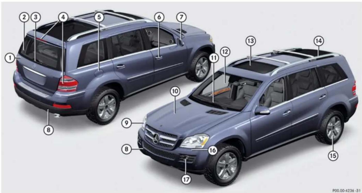
This Operator's Manual describes all features, standard or optional, potentially available for your vehicle at the time of purchase. Please be aware that your vehicle might not be equipped with all features described in this manual.
| Function Page | ||
| 1 | TailgatePower tailgate 91Vehicle tool kit 326 | 90 |
| 2 | Rear window defroster | 223 |
| 3 | Rear window wiperWiper blade, replacing 395Wiper blade, cleaning 322 | 123 |
| 4 | Rear lamps | 388 |
| 5 | Fuel filler flapFuel requirements 436 | 265 |
| 6 | DoorsLocking and unlocking 84Opening 88 |
| Function Page | ||
| Locking and unlocking manually 384 | ||
| 7 | Exterior rear view mirrorsPower folding 112 | 111 |
| 8 | Towing eyes | 413 |
| 9 | Front lamps | 388 |
| 10 | HoodEngine oil 269Coolant 271 | 267 |
| 11 | WipersWiper blades, replacing 395Wiper blades, cleaning 322 | 122 |
| 12 | Windshield | 322 |
| Function Page | ||
| Cleaning with wiper fluid 122 | ||
| Cleaning | 322 | |
| 13 | Power tilt/sliding sunroof | 224 |
| 14 | Roof rails/Carriers | 229 |
| Crossbars | 229 | |
| 15 | Tires and wheels | 272, 425 |
| Checking tire inflation pressure | 281 | |
| Spare wheel | 329 | |
| Flat tire | 397 | |
| 16 | Headlamp cleaning system | 119 |
| 17 | Front fog lamp | 388 |
At a glance
Cockpit
Cockpit
text_image
Interior view of a Mercedes-Benz car with numbered component labels and dashboard controlsAt a glance
Cockpit
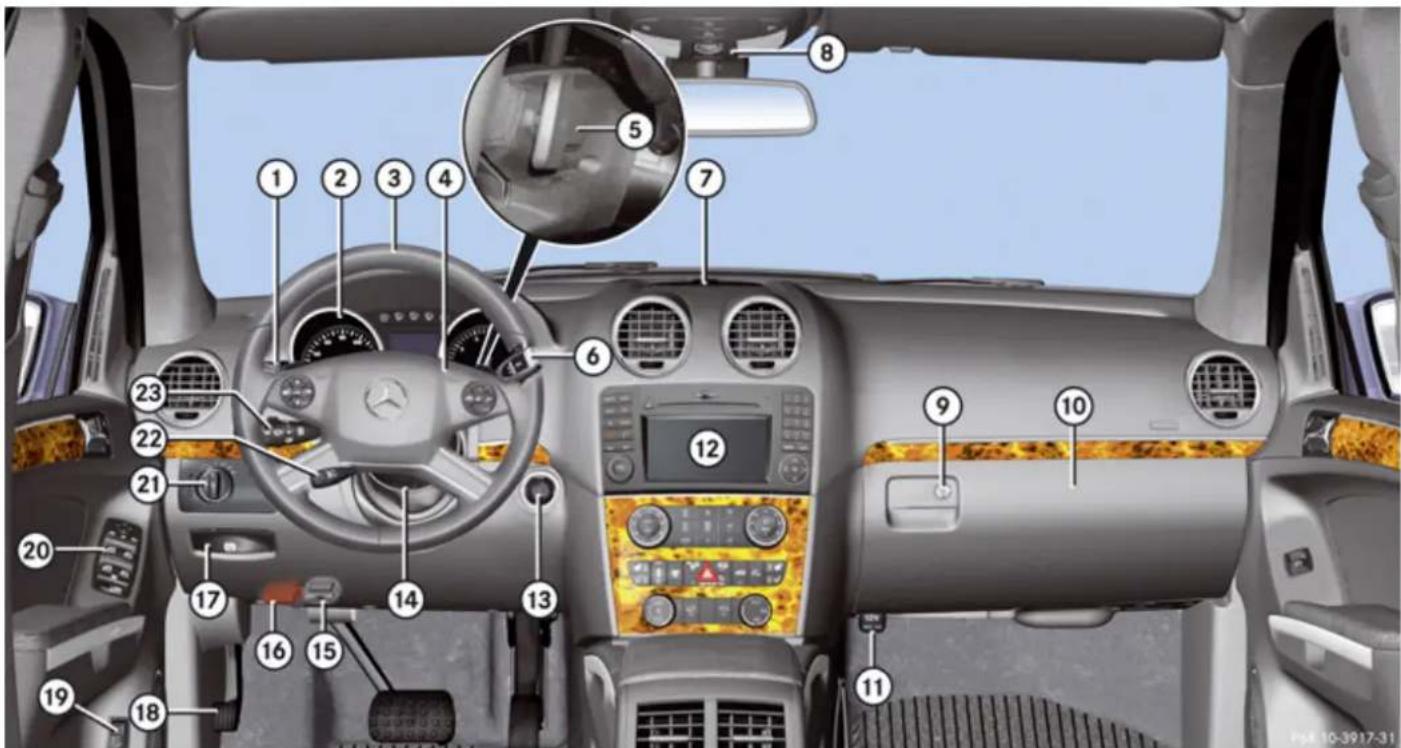
| Function Page | ||
| 1 | Cruise control lever | |
| • Cruise control | 170 | |
| • Distronic | 172 | |
| 2 | Instrument cluster 32, | 147 |
| 3 | Multifunction steering wheel | 38, 148 |
| 4 | Horn | |
| 5 | Steering wheel gearshift control 140 | |
| 6 | Gear selector lever | 135 |
| 7 | Front Parktronic warning indicators 195 | |
| 8 | Overhead control panel | 43 |
| Function Page | ||
| 9 | Glove box lid release, glove box lock 242 | |
| 10 | Glove box | 242 |
| 11 | Power outlet | 249 |
| 12 | Center console | 40 |
| 13 | Starter switch | 95 |
| 14 | Steering wheel adjustment, manual 108 | |
| 15 | On-board diagnostics (OBD) socket | |
| 16 | Hood lock release | 268 |
| 17 | Parking brake release | 133 |
| Function Page | ||
| 18 | Parking brake pedal | 133 |
| 19 | Remote tailgate switch, power tailgate 94 | |
| 20 | Door control panel | 44 |
| 21 | Exterior lamp switch | 115 |
| 22 | Steering wheel adjustment, electrical 109 Heated steering wheel 110 | |
| 23 | Combination switch | |
| Turn signals | 118 | |
| Wipers | 122 | |
| High beam | 118 |
At a glance
Instrument cluster
Instrument cluster
text_image
① ② ③ ④ ⑤ ⑦ BRAKE mph LIM 6 120 140 160 x1000 1/minP54.30-9778-31
At a glance
Instrument cluster
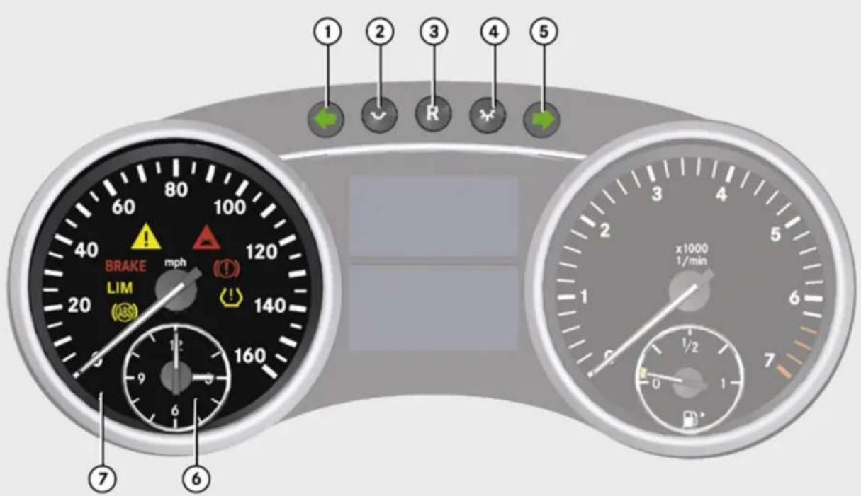
| Function Page | ||
| 1 | ← Left turn signal indicator lamp | |
| 2 | To dim instrument cluster illumination 147 | |
| 3 | Reset button for: · Resetting trip odometer · Resetting all settings | 148 157 |
| 4 | To brighten instrument cluster illumination | 147 |
| Function Page | ||
| 5 | Right turn signal indicator lamp | |
| 6 | Clock | 160 |
| 7 | Speedometer with:Antilock Brake System (ABS) indicator lampLIM Variable speed limiter indicator lamp^2 | 371 |
| Function Page | |
| BRAKE Brake warning lamp, USA only | 372 |
| ESP® warning lamp | 376 |
| Distance warning lamp3 | 377 |
| Brake warning lamp, Canada only | 373 |
| Combination low tire pressure/TPMS malfunction telltale, USA only | 283, 380 |
2 Lamp without function. It illuminates when the ignition is on. It should go out when the engine is running.
3 Vehicles without Distronic: Warning lamp without function. It illuminates when the ignition is on. It should go out when the engine is running.
At a glance
Instrument cluster
text_image
mph 149.8 Miles 26753 +72°F R N P D SRS x1000 1/min CHECK ENGINE 10P54.30-9781-31
At a glance
Instrument cluster
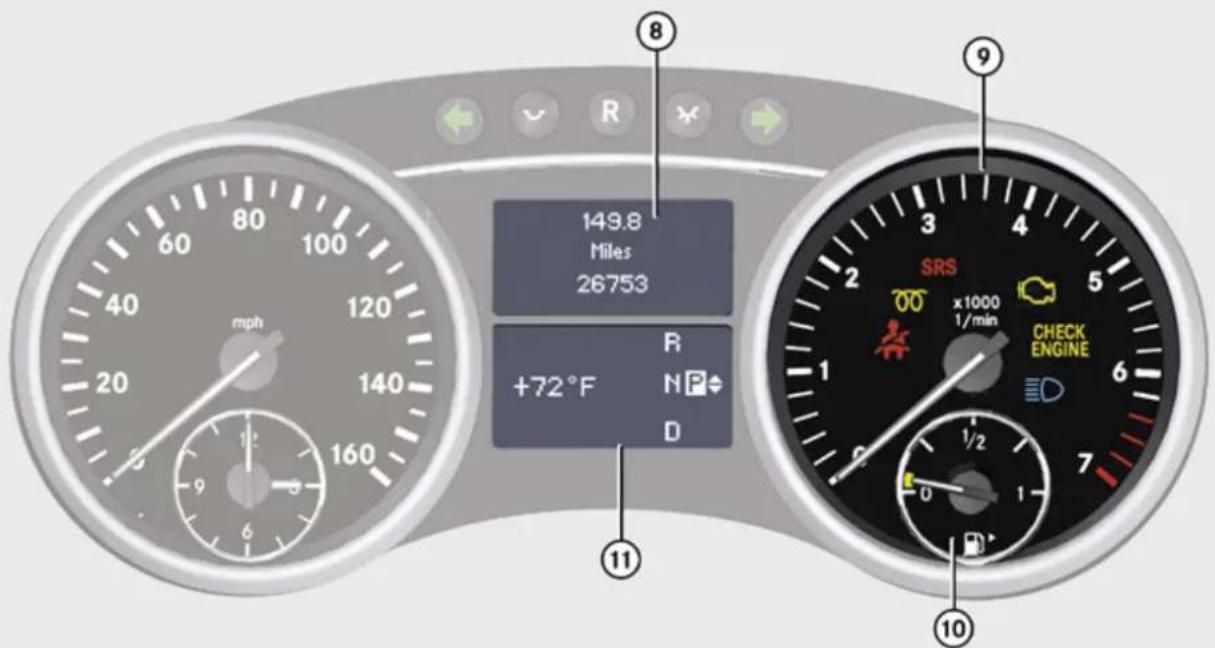
| Function Page | ||
| 8 | Multifunction display with: | 150 |
| • Trip odometer | 148 | |
| • Main odometer | 150 | |
| 9 | Tachometer with:Seat belt telltale 64, | 374 |
| ○○ Preglow indicator lamp, diesel engine only | 129 | |
| SRS Supplemental Restraint System (SRS) indicator lamp | 47,375 | |
| ○○ Engine malfunction indicator lamp, Canada only | 379 | |
| CHECK ENGINE Engine malfunction indicator lamp, USA only | 379 |
| Function Page | ||
| EDHigh-beam headlamp indicator lamp | 118 | |
| 10 | Fuel gauge with:Fuel tank reserve warning lamp 378Fuel filler flap indicator: The fuel filler flap is located on the rear right-hand side. 265 | |
| 11 | Multifunction display with: | 150 |
| Function Page | |
| Outside temperature indicator or digital speedometer (depending on selected setting in the control system) | 153, 159 |
| Transmission position indicator | 137 |
| Gear range indicator | 139 |
| LOW RANGE mode indicator | 142 |
| Distance warning function indicator | 164 |
| Rear window wiper indicator | 123 |
| Downhill Speed Regulator (DSR) indicator | 183 |
| Off-road driving program indicator | 185 |
At a glance
Storage compartments
Storage compartments
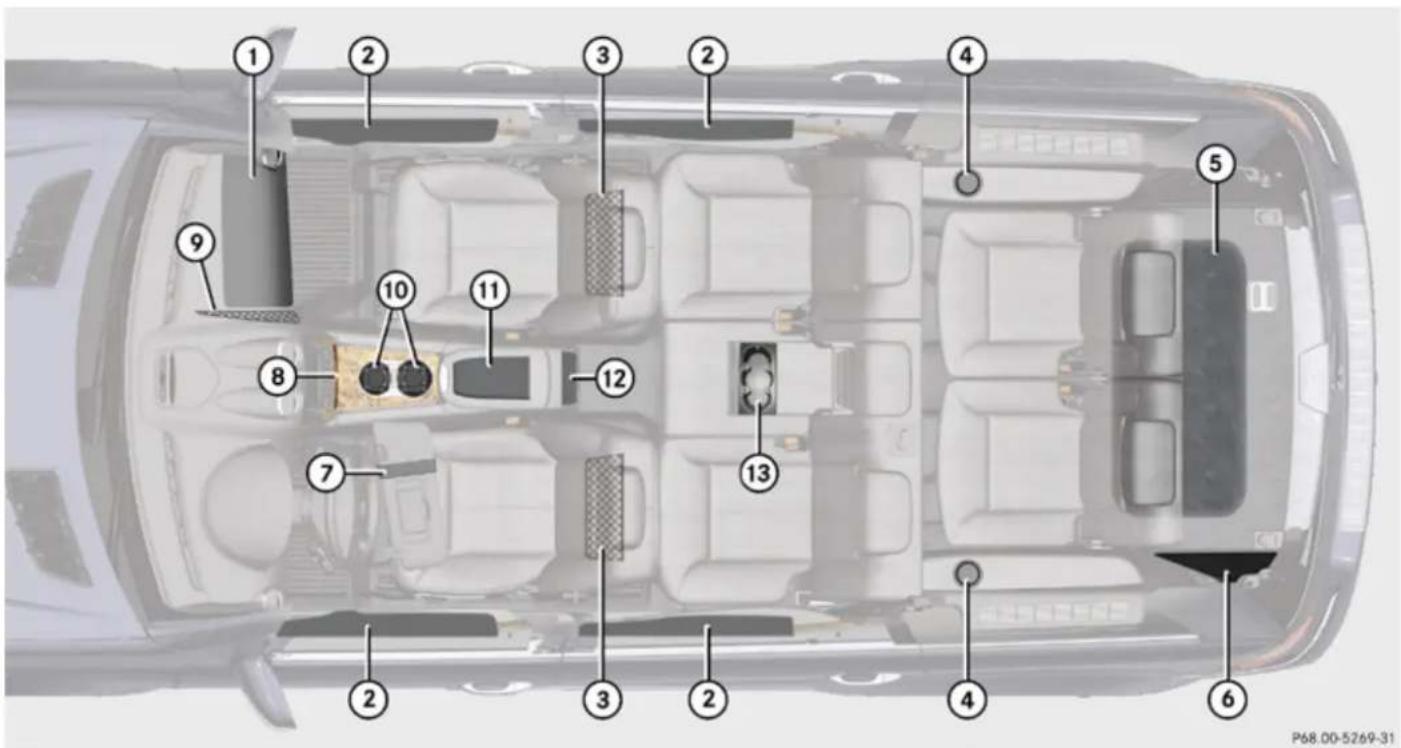
text_image
Top-down diagram of a car interior with numbered components for identification and assembly reference.At a glance
Storage compartments
| Function Page | ||
| 1 | Glove box | 242 |
| 2 | Door pockets | |
| 3 | Parcel nets on front seat backrests 233 | |
| 4 | Cup holders | 245 |
| 5 | Vehicle tool kit, spare wheel | 326 |
| Function Page | ||
| 6 | First aid kit | 326 |
| 7 | Holder, e.g. for gas cards | 246 |
| 8 | Storage compartment | 242 |
| Ashtray 247 | ||
| 9 | Parcel net in front passenger footwell | 233 |
| Function Page | ||
| 10 | Cup holder | 245 |
| 11 | Storage compartment with coin holder 244 | |
| 12 | Rear storage compartments 244 | |
| 13 | Cup holder | 245 |
At a glance
Multifunction steering wheel
Multifunction steering wheel
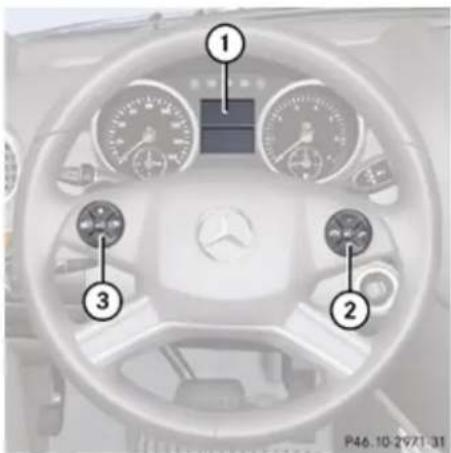
text_image
Top-down view of a car dashboard with numbered labels pointing to key components| Function Page | ||
| 1 | Multifunction display | 150 |
| 2 | Press buttonto take a call | 167 |
| • to dial4 | 167 | |
| • to redial4 | 167 | |
| Press buttonto end a call | 167 | |
| • to reject an incoming call | 167 | |
| Press button + or -to select submenus in the Settings menu | 158 | |
| • to set values | ||
| • to set the volume |
| Function Page | ||
| Press button [icon] to turn the Voice Control System on5, see separate operating instructions | ||
| 3 | Press button [icon] or [icon] to select next/previous menuPress button [icon] or [icon] briefly• to move within a menu• to select previous or next track, scene or stored station within Audio/DVD menu• to switch to the phone book and select a name or number within Telephone menu | 157153167 |
4 Function only available in telephone menu.
5 Vehicles without Voice Control System: Button without function.
At a glance
Multifunction steering wheel
Function Page
Press and hold button


• to select previous or next track with quick search or to select previous or next station in station list or wave band within Audio/DVD menu
153
• to start the quick search in the phone book within Telephone menu
167
Press button OFF to turn the Voice Control System off ^5 , see separate operating instructions
At a glance
Center console
Center console
Upper part (Vehicles without enhanced off-road package)
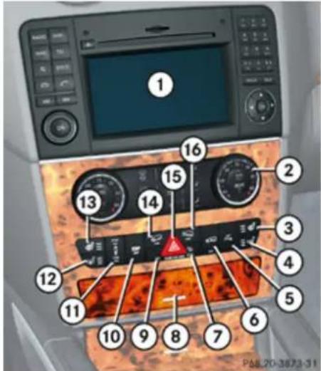
text_image
Diagram of car air conditioning unit with numbered components and a warning triangle indicating safety warning.| Function Page | ||
| 1 | COMAND system, see separate operating instructions | |
| 2 | Climate control3-zone automatic climate control 210Rear window defroster 223 | 202 |
| 3 | Seat heating, front passenger side 107 | |
| 4 | Seat ventilation, front passenger side 107 | |
| 5 | Parktronic system deactivation switch 196 | |
| 6 | Vehicle level control switch | 186 |
| 7 | Front passenger front air bag off indicator lamp | 56 |
| Function Page | ||
| 8 | Storage compartment | 243 |
| 9 | Alarm system indicator lamp 81 | |
| 10 | Electronic Stability Program (ESP®) switch | 79 |
| 11 | Adaptive Damping System (ADS) switch 185 | |
| 12 | Seat ventilation, driver's side 107 | |
| 13 | Seat heating, driver's side | 107 |
| 14 | Switch for Downhill Speed Regulation (DSR) 182 | |
| 15 | Hazard warning flasher switch 118 | |
| 16 | Switch for off-road driving program 185 |
At a glance
Center console
Upper part (Vehicles with enhanced off-road package, Canada only)
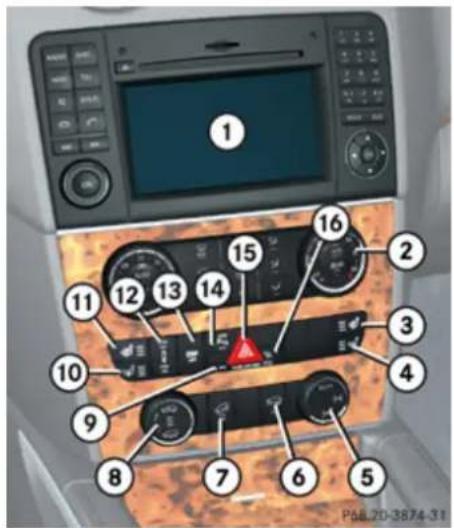
text_image
Diagram of car air conditioning control panel with numbered labels pointing to various controls and a warning icon| Function Page | ||
| 1 | COMAND system, see separate operating instructions | |
| 2 | Climate control3-zone automatic climate control 210Rear window defroster 223 | 202 |
| 3 | Seat heating, front passenger side 107 | |
| 4 | Seat ventilation, front passenger side 107 | |
| 5 | Rotary switch for differential locks 145 | |
| 6 | Switch for LOW RANGE mode 142 | |
| 7 | Switch for Downhill Speed Regulation (DSR) | 182 |
| Function Page | ||
| 8 | Rotary switch for vehicle level control 189 | |
| 9 | Alarm system indicator lamp 81 | |
| 10 | Seat ventilation, driver's side 107 | |
| 11 | Seat heating, driver's side | 107 |
| 12 | Adaptive Damping System (ADS) switch 185 | |
| 13 | Electronic Stability Program (ESP®) switch | 79 |
| 14 | Parktronic system deactivation switch 196 | |
| 15 | Hazard warning flasher switch 118 | |
| 16 | Front passenger front air bag off indicator lamp 56 |
At a glance
Center console
Lower part
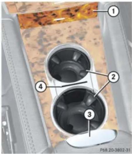
text_image
① ② ③ ④ P68.20-3802-31| Function Page | ||
| 1 | Storage compartment or Ashtray 247 | 243 |
| 2 | Cup holder | 245 |
| 3 | Front armrest storage compartment 244 | |
| 4 | Card, ticket holder | 245 |
At a glance
Overhead control panel
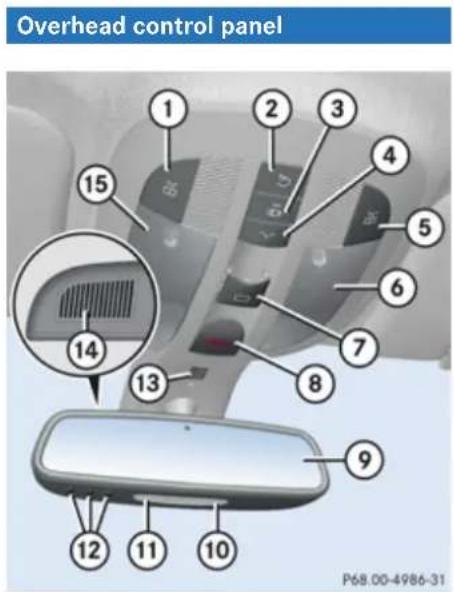
| Function Page | ||
| 1 | Left front reading lamp on/off 120 | |
| 2 | Rear interior lighting on/off | 120 |
| 3 | Automatic interior lighting | 120 |
| 4 | Front interior lighting on/off 120 | |
| 5 | Right reading lamp on/off | 120 |
| 6 | Front right interior lamp | 120 |
| 7 | Power tilt/sliding sunroof switch 224 | |
| 8 | Tele Aid (emergency call system) button 253 | |
| 9 | Interior rear view mirror | 111 |
| 10 | Front right reading lamp | 120 |
| Function Page | ||
| 11 | Front left reading lamp | 120 |
| 12 | Garage door opener | 256 |
| 13 | Vehicles without telephone installed: Hands-free microphone for Tele Aid (emergency call system) and Voice Control System, see separate operating instructions | |
| 14 | Vehicles with telephone installed: Hands-free microphone for Tele Aid (emergency call system), telephone and Voice control system, see separate operating instructions | |
| 15 | Front left interior lamp | 120 |
At a glance
Door control panel
Door control panel
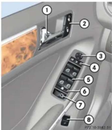
text_image
Car interior panel with numbered labels pointing to different components, likely for diagnostic or navigation instructions.| Function Page | ||
| 1 | Inside door handle | 88 |
| 2 | Central locking/unlocking switch 89 | |
| 3 | Exterior rear view mirror adjustment 111 | |
| 4 | Selection buttons for exterior rear view mirror adjustment 111Power-folding exterior rear view mirrors 112 | |
| 5 | Switches for opening/closing front and rear door windows | 124 |
| Function Page | ||
| 6 | Rear door window override switch 74 | |
| 7 | Hinged quarter window switch 126 | |
| 8 | Remote tailgate switch, power tailgate 91 |
Safety and security
Vehicle equipment 46
Occupant safety 46
Panic alarm 75
Driving safety systems 75
Anti-theft systems 80
natural_image
Abstract 3D-rendered white figure with curved lines, no text or symbols presentSafety and security
Occupant safety
Vehicle equipment
This Operator's Manual describes all features, standard or optional, potentially available for your vehicle at the time of purchase. Please be aware that your vehicle might not be equipped with all features described in this manual.
Occupant safety
Introduction
In this section you will learn the most important facts about the restraint system components of the vehicle.
The restraint systems are
- Seat belts
- Child restraints
- Lower Anchors and Tethers for CHildren (LATCH)
Additional protection potential is provided by:
• Supplemental Restraint System (SRS) with
- Air bags
- Air bag control unit (with crash sensors)
- Emergency Tensioning Device (ETD) for seat belts
- Seat belt force limiter
• Active head restraints
• Preventive occupant safety (PRE-SAFE®)
• Air bag system components with
- Front passenger front air bag off indicator lamp
- USA only: Front passenger seat with Occupant Classification System (OCS)
- Canada only: Front passenger seat with BabySmart™ air bag deactivation system
Although the systems are independent, their protective functions work in conjunction with each other.
Warning!
Modifications to or work improperly conducted on restraint system components or their wiring, as well as tampering with interconnected electronic systems, can lead to the restraint systems no longer functioning as intended.
Air bags or Emergency Tensioning Devices (ETDs), for example, could deploy inadvertently or fail to deploy in accidents although the deceleration threshold for air bag deployment is exceeded. Therefore, never modify the restraint systems. Do not tamper with electronic components or their software.
For information on infants and children traveling with you in the vehicle and restraint systems for infants and children, see “Children in the vehicle” (▷ page 68).
SRS indicator lamp
The SRS system conducts a self-test when the ignition is switched on and in regular intervals while the engine is running. This facilitates detection of system malfunctions.
The SRS indicator lamp in the instrument cluster comes on when the ignition is switched on and goes out no later than a few seconds after the engine has been started. The SRS components are in operational readiness if the SRS indicator lamp is not lit when the engine is running.
A malfunction in the system has been detected if the SRS indicator lamp
• fails to go out after approximately 4 seconds after the engine is started
• does not come on at all
- comes on after the engine was started or while driving
Warning!
In the event that the SRS indicator lamp comes on while driving or does not come on at all, the SRS self-check has detected a malfunction. For your safety, we strongly recommend that you contact an authorized Mercedes-Benz Center immediately to have the system checked; otherwise the SRS may not deploy when needed in an accident, which could result in serious or fatal injury, or it might deploy unexpectedly and unnecessarily which could also result in injury.
In addition, improper work on the SRS creates a risk of rendering the SRS inoperative or causing unintended air bag deployment. Work on the SRS must therefore only be performed by qualified technicians. Contact an authorized Mercedes-Benz Center.
If it is necessary to modify an air bag system to accommodate a person with disabilities, contact an authorized Mercedes-Benz Center or call our Customer Assistance Center at 1-800-FOR-MERCedes (1-800-367-6372) for details.
Air bags
Warning!
Air bags are designed to reduce the potential of injury and fatality in certain frontal impacts (front air bags, driver side knee bag), side impacts (side impact air bags and window curtain air bags), or rollovers (window curtain air bags). However, no system available today can completely eliminate injuries and fatalities. The deployment of the air bags temporarily releases a small amount of dust from the air bags. This dust, however, is neither injurious to your health, nor does it indicate a fire in the vehicle. The dust might cause some temporary breathing difficulty for people with asthma or other breathing trouble. To avoid this, you may wish to get out of the vehicle as soon as it is safe to do so. If you have any breathing difficulty but cannot get out of the vehicle after the air bag inflates, then get fresh air by opening a window or door.
Warning!
To reduce the risk of injury when the front air bags inflate, it is very important for the driver and front passenger to always be in
Safety and security
Occupant safety
a properly seated position and to wear their respective seat belt.
For maximum protection in the event of a collision always be in normal seated position with your back against the seat backrest. Fasten your seat belt and make sure it is properly positioned on your body. Since the air bag inflates with considerable speed and force, a proper seating position and correct positioning of the hands on the steering wheel will help to keep you at a safe distance from the air bag. Occupants who are not wearing their seat belt, are not seated properly or are too close to the air bag can be seriously injured or killed by an air bag as it inflates with great force instantaneously:
- Sit with the seat belt properly fastened in a position that is as upright as possible with your back against the seat backrest.
- Move the driver seat as far back as possible, still permitting proper operation of vehicle controls. The distance from the center of the driver's chest to the center of the air bag cover on the steering wheel must be at least 10 inches (25 cm) or more. You should be able to accomplish this by adjusting
the seat and steering wheel. If you have any difficulties, please contact an authorized Mercedes-Benz Center.
- Do not lean your head or chest close to the steering wheel or dashboard.
- Keep hands on the outside of the steering wheel rim. Placing hands and arms inside the rim can increase the risk and potential severity of hand/arm injury when the driver's front air bag inflates.
- Adjust the front passenger seat as far as possible rearward from the dashboard when the seat is occupied.
- Occupants, especially children, should never place their bodies or lean their heads in the area of the door where the side impact air bag inflates. This could result in serious injuries or death should the side impact air bag be deployed. Always sit as upright as possible, wear the seat belt properly and use an appropriately sized infant restraint, toddler restraint, or booster seat recommended for the size and weight of the child.
• Canada only: Children 12 years old and under must never ride in the front seat,
except in a Mercedes-Benz authorized BabySmart™ compatible child seat, which operates with the BabySmart™ air bag deactivation system installed in the vehicle to deactivate the front passenger front air bag when it is installed properly. Otherwise they will be struck by the air bag when it inflates in a crash. If this happens, serious or fatal injury will result.
Failure to follow these instructions can result in severe injuries to you or other occupants.
If you sell your vehicle, it is important that you make the buyer aware of this safety information. Be sure to give the buyer this Operator's Manual.
Warning!
Accident research shows that the safest place for children in an automobile is in the rear seat.
There is a possibility for a side impact air bag related injury if occupants, especially children, are not properly seated or restrained when next to a side impact air bag which needs to deploy rapidly in a side impact in order to do its job.
Safety and security
Occupant safety
To help avoid the possibility of injury, please follow these guidelines:
(1) Always sit as upright as possible, properly use the seat belts, and for children 12 years old and under, use an appropriately sized infant restraint, toddler restraint, or booster seat recommended for the size and weight of the child.
(2) Always wear seat belts properly.
Air bags are designed to deploy only in certain frontal impacts (front air bags, driver side knee bag), side impacts (side impact and window curtain air bags) which exceed preset deployment thresholds, and in certain rollovers (window curtain air bags). Only in the event of such a situation will they provide their supplemental protection.
The driver and passengers should always wear their seat belts. Otherwise it is not possible for the air bags to provide their supplemental protection.
In case of other types of impacts and impacts below air bag deployment thresholds, air bags will not deploy. The driver and passengers will then be protected to the extent possible by a properly fastened seat
belt. A properly fastened seat belt is also needed to provide the best possible protection in a rollover.
Air bags are not a substitute for seat belts. Always wear your seat belt, regardless of whether or not your vehicle is equipped with air bags.
It is important to your safety and that of your passengers that you replace deployed air bags and repair any malfunctioning air bags to make sure the vehicle will continue to provide supplemental crash protection for occupants.
Safety guidelines for the seat belt, Emergency Tensioning Device (ETD) and air bag
Warning!
- Damaged seat belts or seat belts that have been subjected to stress in an accident must be replaced and their anchoring points must also be checked. Only use seat belts installed or supplied by an authorized Mercedes-Benz Center.
• Air bags and pyrotechnic emergency tensioning devices (ETDs) contain perchlorate material, which may require
special handling and regard for the environment. Check with your local government's disposal guidelines. California residents, see www.dtsc.ca.gov/HazardousWaste/Perchlorate/index.cfm.
- Air bags and ETDs are designed to function on a one-time-only basis. An air bag or ETD that is deployed must be replaced. PRE-SAFE ^ has electrically operated reversible pre-tensioners in addition to the pyrotechnic ETDs.
- Do not pass seat belts over sharp edges. They could tear.
- Do not make any modification that could change the effectiveness of the seat belts.
- Do not bleach or dye seat belts as this may severely weaken them. In a crash they may not be able to provide adequate protection.
- No modifications of any kind may be made to any components or wiring of the SRS. This includes changing or removing any component or part of the SRS, the installation of additional trim material, seat covers, badges, etc. over the
Safety and security
Occupant safety
steering wheel hub, front passenger front air bag cover, outboard sides of the seat backrests, door trim panels, or door frame trims, and installation of additional electrical/electronic equipment on or near SRS components and wiring. Keep area between air bags and occupants free of objects (e.g. packages, purses, umbrellas, etc.).
- Do not hang items such as coat hangers from the coat hooks or handles over the door. These items may be thrown around in the vehicle and cause head and other injuries when the window curtain air bag is deployed.
• Air bag system components will be hot after an air bag has inflated. Do not touch them. - Never place your feet on the instrument panel, dashboard, or on the seat. Always keep both feet on the floor in front of the seat.
- In addition, improper repair work on the SRS creates a risk of rendering the SRS inoperative or causing unintended air bag deployment. Work on the SRS must therefore only be performed by qualified
technicians. Contact an authorized Mercedes-Benz Center.
- For your protection and the protection of others, when scrapping the air bag unit or ETD, our safety instructions must be followed. These instructions are available from any authorized Mercedes-Benz Center.
- Given the considerable deployment speed, required inflation volume, and the material of the air bags, there is the possibility of abrasions or other, potentially more serious injuries resulting from air bag deployment.
If you sell your vehicle, we strongly recommend that you inform the subsequent owner that the vehicle is equipped with SRS and refer them to the applicable section in the Operator's Manual.
Front air bags
⚠️ Observe Safety notes, see page 49.
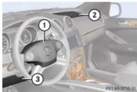
text_image
Interior view of a car dashboard with numbered components for identification① Driver front air bag
② Front passenger front air bag
③ Knee bag
The front air bags are designed to provide increased protection for the driver and front passenger against the risk of injuries to the head and thorax.
Driver and front passenger front air bags and driver's side knee bag are deployed
• in the event of certain frontal impacts
- if impact exceeds a preset deployment threshold
Safety and security
Occupant safety
- if the system determines that air bag deployment can offer additional protection to that provided by the seat belt
• depending on whether the seat belt is in use - independently of the side impact air bags and/or the window curtain air bags
The front air bags in this vehicle have been designed to inflate in two stages. This allows the air bags to have different rates of inflation that are based on the vehicle deceleration rate as assessed by the air bag control unit. Vehicles with OCS, USA only: On the front passenger side, front air bag ② deployment is additionally influenced by the passenger's weight category as identified by the Occupant Classification System (OCS) (> page 53). Vehicles with OCS, USA only: The lighter the front passenger side occupant, the higher the vehicle deceleration rate required for second stage inflation of front air bag ②.
The air bags will not deploy in impacts which do not exceed the system's preset deployment thresholds. You will then be protected by the fastened seat belts.
The front air bags will not be deployed in the event of a rollover unless the vehicle's rate of longitudinal deceleration or acceleration exceeds the preset deployment threshold for the front air bags.
The front passenger front air bag ② will only be deployed if
- vehicles with OCS, USA only: the system, based on OCS weight sensor readings, detects that the front passenger seat is occupied
- the X_2^* PASS AIR BAG OFF indicator lamp in the center console is not lit (USA only: (▶ page 56), Canada only: (▶ page 58))
- the impact exceeds a preset deployment threshold
! Vehicles with BabySmart™ air bag deactivation system, Canada only: Do not place objects heavier than 20 lb (9 kg) on the front passenger seat. This could cause the front or side impact air bag on the front passenger side to deploy in a crash which exceeds the system's deployment threshold.
Knee bag
The knee bag ③ is located on the driver side lower instrument panel. It is designed to operate together with the driver front air bag in certain frontal impacts exceeding a preset deployment threshold. The knee bag ③ operates best in conjunction with a properly positioned and fastened seat belt.
Side impact air bags

Observe Safety notes, see page 49.

Warning!
The pressure sensors for side impact air bag control are located in the doors. Do not modify any components of the doors or door trim panels including, for example, the addition of door speakers.
Improper repair work on the doors or the modification or addition of components to the doors create a risk of rendering the side impact air bags inoperative or causing unintended air bag deployment. Work on the doors must therefore only be performed by qualified technicians.
Contact an authorized Mercedes-Benz Center
Safety and security
Occupant safety
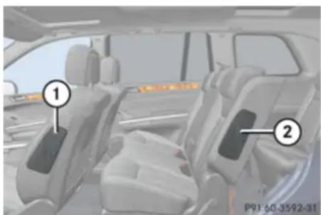
natural_image
Interior view of a modern car showing two seats with labeled parts (1 and 2), no visible text or symbols beyond labels.① Front side impact air bag
② Rear side impact air bag
When deployed, the side impact air bags are designed to provide increased protection for the thorax (but not the head, neck and arms) of the occupants on the side of the vehicle on which the impact occurs.
The side impact air bags are deployed
• on the impacted side of the vehicle
- in side impacts exceeding a preset deployment threshold
• regardless of whether the seat belt is in use
• independently of the front air bags
• independently of the ETDs
Vehicles with OCS, USA only: The front passenger side impact air bag will not deploy if the OCS senses that the front passenger seat is empty and the front passenger seat belt is not fastened (latch plate is not inserted into the buckle). With an empty front passenger seat and the seat belt fastened (latch plate properly inserted into buckle) the front passenger side impact air bag will deploy independently of the empty seat.
The side impact air bags are not deployed in side impacts which do not exceed the system's deployment threshold.
The side air bags will not be deployed in the event of a rollover unless the vehicle's rate of lateral deceleration or acceleration exceeds the preset deployment threshold for the side air bags.
! Vehicles with BabySmart™ air bag deactivation system, Canada only: Do not place objects heavier than 20 lb (9 kg) on the front passenger seat. This could cause the front or side impact air bag on the front passenger side to deploy in a crash which exceeds the system's deployment threshold.
Warning!
Only use seat covers which have been tested and approved by Mercedes-Benz for your vehicle model. Using other seat covers
may interfere with or prevent the deployment of the side impact air bags. Contact an authorized Mercedes-Benz Center for availability.
Window curtain air bags
⚠️ Observe Safety notes, see page 49.
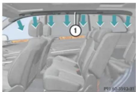
natural_image
Interior view of a car showing seats and dashboard with directional arrows indicating flow or movement (no text or symbols)① Window curtain air bag
When deployed, window curtain air bags ① are designed to provide increased protection for the head (but not the chest or arms) of the occupants on the side of the vehicle on which the impact occurs.
Safety and security
Occupant safety
Window curtain air bags ① are deployed
• on the impacted side of the vehicle
- in side impacts exceeding a preset deployment threshold
• independently of the front air bags
- regardless of whether the front passenger seat is occupied
- regardless of whether the seat belt is in use
- in certain vehicle rollovers, if the system determines that air bag deployment can offer additional protection to that provided by the seat belt
Window curtain air bags ① are not deployed in impacts which do not exceed the system's deployment threshold.
Window curtain air bags ① deploy in the area indicated by the arrows.
Occupant Classification System
The Occupant Classification System (OCS) is standard equipment in USA.
The OCS automatically turns the front passenger front air bag on or off based on the classified occupant weight category determined by weight sensor readings from the front passenger seat.
The system does not deactivate the front passenger side impact air bag, the window curtain air bag and the Emergency Tensioning Devices (ETDs).
Occupants must sit with the seat belt properly fastened in a position that is as upright as possible with their back against the seat backrest and feet on the floor to be correctly classified. If the occupant's weight is transferred to another object in the vehicle (e.g. by leaning on armrests), the OCS may not be able to properly approximate the occupant's weight category.
Furthermore, the occupant weight may appear to increase or decrease due to the following: objects hanging on the seat, lodged underneath the seat, stuffed between the seat and middle console or the seat and door, other passengers pushing on the seat, or objects applying pressure to the back of the seat. Always make sure the seat has clearance in all directions at all times.
If your seat, including the trim cover and cushion, needs to be serviced in any way, take the vehicle to an authorized Mercedes-Benz Center.
Only seat accessories approved by Mercedes-Benz may be used.
Both the driver and the front passenger should always use the ✕PASS AIR BAG OFF
indicator lamp as an indication of whether or not the front passenger is properly positioned.

Warning!
If the 2 PASS AIR BAG OFF indicator lamp illuminates when an adult or someone larger than a small individual is in the front passenger seat, have the front passenger re-position himself or herself in the seat until the 2 PASS AIR BAG OFF indicator lamp goes out, or check whether objects are caught under or around the seat. In the event of a collision, the air bag control unit will not allow front passenger front air bag deployment when the OCS has classified the front passenger seat occupant as weighting as much as or less
Safety and security
Occupant safety
than a typical 12-month-old child in a standard child restraint or if the front passenger seat is classified as being empty. When the OCS senses that the front passenger seat occupant is classified as being up to or less than the weight of a typical 12-month-old child in a standard child restraint, the PASS AIR BAG OFF indicator lamp will illuminate when the engine is started and remain illuminated, indicating that the front passenger front air bag is deactivated.
When the OCS senses that the front passenger seat is classified as being empty, the PASS AIR BAG OFF indicator lamp will illuminate when the engine is started and remain illuminated, indicating that the front passenger front air bag is deactivated. When the OCS senses that the front passenger seat occupant is classified as being heavier than the weight of a typical 12-month-old child seated in a standard child restraint or as being a small individual (such as a young teenager or a small adult), the PASS AIR BAG OFF indicator lamp will illuminate for approximately 6 seconds when the engine is started and then, depending on occupant weight sensor
readings from the seat, remain illuminated or go out. With the PASS AIR BAG OFF indicator lamp illuminated, the front passenger front air bag is deactivated. With the PASS AIR BAG OFF indicator lamp out, the front passenger front air bag is activated. When the OCS senses that the front passenger seat occupant is classified as an adult or someone larger than a small individual, the PASS AIR BAG OFF indicator lamp will illuminate for approximately 6 seconds when the engine is started and then go out, indicating that the front passenger front air bag is activated. If the PASS AIR BAG OFF indicator lamp is illuminated, the front passenger front air bag is deactivated and will not be deployed. If the PASS AIR BAG OFF indicator lamp is not illuminated, the front passenger front air bag is activated and will be deployed • in the event of certain frontal impacts • if impact exceeds a preset deployment threshold • independently of the side impact air bags
If the front passenger front air bag is deployed, the rate of inflation will be influenced by - the rate of relevant vehicle deceleration as assessed by the air bag control unit - the front passenger's weight category as identified by the OCS
For information about air bag display messages (▷ page 335).
Warning!
According to accident statistics, children are safer when properly restrained in the rear seating positions than in the front seating position. Thus, we strongly recommend that children be placed in the rear seats whenever possible. Regardless of seating position, children 12 years old and under must be seated and properly secured in an appropriate infant restraint, toddler restraint, or booster seat recommended for the size and weight of the child. The infant or child restraint must be properly secured with the vehicle's seat belt, the seat belt and top tether strap, or lower anchors and top tether strap, fully in
Safety and security
Occupant safety
accordance with the child seat manufacturer's instructions.
Occupants, especially children, should always sit as upright as possible, wear the seat belt properly and use an appropriately sized infant restraint, toddler restraint, or booster seat recommended for the size and weight of the child.
Children can be killed or seriously injured by an inflating air bag. Note the following important information when circumstances require you to place a child in the front passenger seat:
- Your vehicle is equipped with air bag technology designed to deactivate the front passenger front air bag in your vehicle when the system senses the weight of a typical 12-month-old child or less along with the weight of a standard appropriate child restraint on the front passenger seat.
- A child in a rear-facing child restraint on the front passenger seat will be seriously injured or even killed if the front passenger front air bag inflates in a collision which could occur under some circumstances, even with the air bag technology installed in your vehicle. The
only means to completely eliminate this risk is to never place a child in a rear-facing child restraint in the front seat. We therefore strongly recommend that you always place a child in a rear-facing child restraint in a backseat.
- If you must install a rear-facing child restraint on the front passenger seat because circumstances require you to do so, make sure the PASS AIR BAG OFF indicator lamp is illuminated, indicating that the front passenger front air bag is deactivated. Should the PASS AIR BAG OFF indicator lamp not illuminate or go out while the restraint is installed, please check installation. Periodically check the
PASS AIR BAG OFF indicator lamp while driving to make sure the
PASS AIR BAG OFF indicator lamp is
illuminated. If the PASS AIR BAG OFF indicator lamp goes out or remains out, do not transport a child on the front passenger seat until the system has been repaired.
A child in a rear-facing child restraint on the front passenger seat will be seriously
injured or even killed if the front passenger front air bag inflates.
- If you have to place a child in a forward-facing child restraint on the front passenger seat, move the seat as far back as possible, use the proper child restraint recommended for the age, size and weight of the child, and secure child restraint with the vehicle's seat belt according to the child seat manufacturer's instructions. For children larger than the typical 12-month-old child, the front passenger front air bag may or may not be activated.
Deployment of the driver front air bag does not mean that the front passenger front air bag also should have deployed.
The OCS may have determined:
- that the seat was empty or occupied by the weight up to or less than that of a typical 12-month-old child seated in a standard child restraint – both instances where the system suppresses deployment of the front passenger front air bag even though the impact met the criteria and was of
Safety and security
Occupant safety
sufficient severity to deploy the driver front air bag
- that the seat was occupied by a small individual (such as a young teenager or a small adult) or a child who weighs more than the weight of a typical 12-month-old child in a standard child restraint – both of which are instances where the system may suppress deployment of the front passenger front air bag even though the impact met the criteria and was of sufficient severity to deploy the driver front air bag
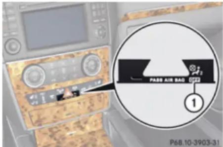
text_image
PASS AIR BAG ① P68.10-3903-31① Front passenger front air bag off indicator lamp
The PASS AIR BAG OFF indicator lamp ① will be illuminated, except with the SmartKey
removed from the starter switch or with the starter switch in position 0.
Warning!
If the SRS indicator lamp and the
PASS AIR BAG OFF indicator lamp are lit at the same time, there is a malfunction in the OCS. The front passenger front air bag will be deactivated in this case. Have the system checked as soon as possible by qualified technicians. Contact an authorized Mercedes-Benz Center.
Only have the seat repaired or replaced at an authorized Mercedes-Benz Center. In order to ensure proper operation of the air bag system and OCS:
- Do not place more than 4.4 lb (2 kg) into the storage bag on the back of the front passenger seat. Otherwise, the OCS may not be able to properly approximate the occupant weight category.
- Do not place objects under and/or around the front passenger seat.
- Do not hang anything from or attach any items to the seats.
- Do not stuff objects such as books between the front passenger seat and
the center console or front passenger door.
- Do not move the front passenger seat backwards against stiff objects.
- Sit with the seat belt properly fastened in a position that is as upright as possible with your back against the seat backrest.
- While seated, an occupant should not position him/herself in such a way as to cause the occupant's weight to be lifted from the seat bottom as this may result in the OCS being unable to correctly approximate the occupant's weight category.
- Read and observe all warnings in this chapter.
Occupant Classification System Self-test
After turning the SmartKey in the starter switch to position 1 or 2 or pressing the KEYLESS-GO start/stop button once or twice, the PASS AIR BAG OFF indicator lamp illuminates. If an adult occupant is properly sitting on the front passenger seat and the system classifies the occupant as an adult, the PASS AIR BAG OFF indicator lamp will
Safety and security
Occupant safety
illuminate and go out after approximately 6 seconds.
If the seat is not occupied and the system classifies the front passenger seat as being empty, the ☑ PASS AIR BAG OFF indicator lamp will illuminate and not go out.

Warning!
If the Pass AIR BAG OFF indicator lamp does not illuminate, the system is not functioning. You must contact an authorized Mercedes-Benz Center before seating any child on the front passenger seat.
For more information, see the “Practical hints” section (▷ page 381).

Warning!
Never place anything between seat cushion and child seat (e.g. pillow), since it reduces the effectiveness of the OCS. The bottom of the child seat must make full contact with the passenger seat cushion. An incorrectly mounted child seat could cause injuries to the child in case of an accident, instead of increasing protection for the child.
Follow the manufacturer's instructions for installation of child seats.
BabySmart™ air bag deactivation system
The BabySmart ^TM air bag deactivation system is standard equipment in Canada.

Warning!
According to accident statistics, children are safer when properly restrained in the rear seating positions than in the front seating position. Thus, we strongly recommend that children be placed in the rear seats whenever possible. Regardless of seating position, children 12 years old and under must be seated and properly secured in an appropriate infant restraint, toddler restraint, or booster seat recommended for the size and weight of the child.
The infant or child restraint must be properly secured with the vehicle's seat belt, the seat belt and top tether strap, or lower anchors and top tether strap, fully in accordance with the child seat manufacturer's instructions.
Occupants, especially children, should always sit as upright as possible, wear the seat belt properly and use an appropriately sized infant restraint, toddler restraint, or booster seat recommended for the size and weight of the child.
Children can be killed or seriously injured by an inflating air bag. Note the following important information when circumstances require you to place a child in the front passenger seat:
- Children 12 years old and under must never ride in the front seat, except in a Mercedes-Benz authorized BabySmart™ compatible child seat, which operates with the BabySmart™ system installed in the vehicle to deactivate the front passenger front air bag when it is installed properly. Otherwise they will be struck by the air bag when it inflates in a crash. If this happens, serious or fatal injury will result.
- A child in a rear-facing child restraint on the front passenger seat will be seriously injured or even killed if the front passenger front air bag inflates in a collision which could occur under some circumstances, even with the air bag technology installed in your vehicle. The only means to completely eliminate this risk is to never place a child in a rear-
Safety and security
Occupant safety
facing child restraint in the front seat. We therefore strongly recommend that you always place a child in a rear-facing child restraint in a backseat.
- If you must install a BabySmart™ compatible rear-facing child restraint on the front passenger seat because circumstances require you to do so, make sure the PASS AIR BAG OFF indicator lamp is illuminated, indicating that the front passenger front air bag is deactivated. Should the PASS AIR BAG OFF indicator lamp not illuminate or go out while the restraint is installed, please check installation. Periodically check the
PASS AIR BAG OFF indicator lamp while driving to make sure the
PASS AIR BAG OFF indicator lamp is illuminated. If the PASS AIR BAG OFF
indicator lamp goes out or remains out, do not transport a child on the front passenger seat until the system has been repaired.
A child in a rear-facing child restraint on the front passenger seat will be seriously
injured or even killed if the front passenger front air bag inflates.
- If you have to place a child in a forward-facing child restraint on the front passenger seat, move the seat as far back as possible, use the proper child restraint recommended for the age, size and weight of the child, and secure child restraint with the vehicle's seat belt according to the child seat manufacturer's instructions.
Warning!
When using a BabySmart™ compatible child seat on the front passenger seat, the front passenger front air bag will not deploy only if the PASS AIR BAG OFF indicator lamp remains illuminated.
Please be sure to check the
PASS AIR BAG OFF indicator lamp every time you use a BabySmart™ compatible child seat on the front passenger seat. Should the PASS AIR BAG OFF indicator lamp go out while the restraint is installed, please check installation. If the PASS AIR BAG OFF indicator lamp remains out, do not use the BabySmart™ restraint to transport a child
on the front passenger seat until the system has been repaired.
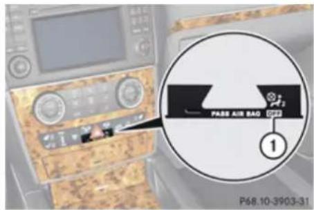
text_image
PASS AIR BAG P68.10-3903-31① Front passenger front air bag off indicator lamp
Special BabySmart™ compatible child seats, designed for use with the Mercedes-Benz system, are required for use with the BabySmart™ air bag deactivation system. Please contact your authorized Mercedes-Benz Center for information on availability. With the special child seat installed properly, the front passenger front air bag will not deploy.
The ✉2 PASS AIR BAG OFF indicator lamp ① will be illuminated, except with the SmartKey removed from the starter switch or with the starter switch in position 0.
The system does not deactivate the side impact air bag, the window curtain air bag and the Emergency Tensioning Device (ETD).
Self-test BabySmart™ without special child seat installed
After turning the SmartKey in the starter switch to position 1 or 2 or pressing the KEYLESS-GO start/stop button once or twice, the PASS AIR BAG OFF indicator lamp comes on for approximately 6 seconds and then goes out.
If the ☐ PASS AIR BAG OFF indicator lamp should not come on or is continuously lit, the system is not functioning. You must see an authorized Mercedes-Benz Center before seating any child on the passenger seat. More information can be found in the “Practical hints” section (▷ page 332).

Warning!
Do not place powered-on laptops, mobile phones, electronic tags such as those used in ski passes and like electronic devices on the front passenger seat. Signals from such devices may interfere with the BabySmart™ air bag deactivation system. Such signal interference may cause the
PASS AIR BAG OFF indicator lamp not to come on during self-test or be continuously lit, indicating that the system is not functioning.

Warning!
The BabySmart ^TM air bag deactivation system will ONLY work with a special child seat designed to operate with it. It will not work with child seats which are not BabySmart ^TM compatible.
Never place anything between seat cushion and child seat (e.g. pillow), since it reduces the effectiveness off the BabySmart™ air bag deactivation system. The bottom of the child seat must make full contact with the passenger seat cushion. An incorrectly mounted child seat could cause injuries to the child in case of an accident, instead of protecting the child.
Follow the manufacturer's instructions for installation of special child seats.
Seat belts
Safety notes
The use of seat belts and infant and child restraint systems is required by law in all 50 states, the District of Columbia, the U.S. territories and all Canadian provinces.
Even where this is not the case, all vehicle occupants should have their seat belts fastened whenever the vehicle is in motion.
For information on infants and children traveling with you in the vehicle and restraint systems for infants and children, see "Children in the vehicle" (▷ page 68).

Warning!
Always fasten your seat belt before driving off. Always make sure all of your passengers are properly restrained. You and your passengers should always wear seat belts.
Failure to wear and properly fasten and position your seat belt greatly increases your risk of injuries and their likely severity in an accident.
If you are ever in an accident, your injuries can be considerably more severe without your seat belt properly buckled. Without
Safety and security
Occupant safety
your seat belt buckled, you are much more likely to hit the interior of the vehicle or be ejected from it. You can be seriously injured or killed.
In the same crash, the possibility of injury or death is lessened if you are properly wearing your seat belt. The air bags can only protect as intended if the occupants are properly wearing their seat belts.

Warning!
Never ride in a moving vehicle with the seat backrest in an excessively reclined position as this can be dangerous. You could slide under the seat belt in a collision. If you slide under it, the seat belt would apply force at the abdomen or neck. That could cause serious or even fatal injuries. The seat backrest and seat belt provide the best restraint when the wearer is in a position that is as upright as possible and the seat belt is properly positioned on the body.

Warning!
Never let more people ride in the vehicle than there are seat belts available. Make sure everyone riding in the vehicle is correctly restrained with a separate seat
belt. Never use a seat belt for more than one person at a time.

Warning!
Damaged seat belts or seat belts that have been subjected to stress in an accident must be replaced and their anchoring points must also be checked.
Only use seat belts which have been approved by Mercedes-Benz.
Do not make any modifications to the seat belts. This can lead to unintended activation of the ETDs or to their failure to activate when necessary.
Do not bleach or dye seat belts as this may severely weaken them. In a crash they may not be able to provide adequate protection.
Have all work carried out only by qualified technicians. Contact an authorized Mercedes-Benz Center.
Proper use of seat belts

Warning!
USE SEAT BELTS PROPERLY
- Seat belts can only work when used properly. Never wear seat belts in any
other way than as described in this section, as that could result in serious injuries in case of an accident.
• Each occupant should wear their seat belt at all times, because seat belts help reduce the likelihood of and potential severity of injuries in accidents, including rollovers. The integrated restraint system includes SRS (driver front air bag, driver side knee bag, front passenger front air bag, side impact air bags, window curtain air bags for side windows), Emergency Tensioning Devices (ETDs), seat belt force limiters, and front seat knee bolsters.
The system is designed to enhance the protection offered to properly belted occupants in certain frontal (front air bags, driver side knee bag and ETDs) and side (side impact air bags, window curtain air bags, and ETDs) impacts which exceed preset deployment thresholds and in certain rollovers (window curtain air bags and ETDs).
- Never wear the shoulder belt under your arm, against your neck or off your shoulder. In a frontal crash, your body would move too far forward. That would
Safety and security
Occupant safety
increase the chance of head and neck injuries. The seat belt would also apply too much force to the ribs or abdomen, which could severely injure internal organs such as your liver or spleen.
Adjust the seat belt so that the shoulder section is located as close as possible to the middle of the shoulder (it should not touch the neck). Never pass the shoulder portion of the seat belt under your arm. For this purpose, you can adjust the height of the seat belt outlet.
- Position the lap belt as low as possible on your hips and not across the abdomen. If the lap belt is positioned across your abdomen, it could cause serious injuries in a crash.
- Never wear seat belts over rigid or breakable objects in or on your clothing, such as eyeglasses, pens, keys etc., as these might cause injuries.
- Make sure the seat belt is always fitted snugly. Take special care of this when wearing loose clothing.
- Never use a seat belt for more than one person at a time. Do not fasten a seat belt
around a person and another person or other objects at the same time.
- Seat belts should not be worn twisted. In a crash, you would not have the full width of the seat belt to distribute impact forces. The twisted seat belt against your body could cause injuries.
- Pregnant women should also always use a lap/shoulder belt. The lap belt portion should be positioned as low as possible on the hips to avoid any possible pressure on the abdomen.
- Place the seat backrest in a position that is as upright as possible.
- Check your seat belt during travel to make sure it is properly positioned.
- Never place your feet on the instrument panel, dashboard, or on the seat. Always keep both feet on the floor in front of the seat.
- When using a seat belt to secure infant restraints, toddler restraints, or children in booster seats, always follow the child seat manufacturer's instructions.
Warning!
Do not pass seat belts over sharp edges. They could tear.
Do not allow the seat belt to get caught in the door or in the seat adjustment mechanism. This could damage the seat belt.
Never attempt to make modifications to seat belts. This could impair the effectiveness of the seat belts.
Do not bleach or dye seat belts as this may severely weaken them. In a crash, they may not be able to provide adequate protection.
Damaged seat belts or seat belts that have been subjected to stress in an accident must be replaced and their anchoring points must also be checked. Contact an authorized Mercedes-Benz Center.
Fastening the seat belts
Warning!
Always fasten your seat belt before driving off. Always make sure all of your passengers are properly restrained. You and your passengers should always wear seat belts.
Safety and security
Occupant safety
Failure to wear and properly fasten and position your seat belt greatly increases your risk of injuries and their likely severity in an accident.
If you are ever in an accident, your injuries can be considerably more severe without your seat belt properly buckled. Without your seat belt buckled, you are much more likely to hit the interior of the vehicle or be ejected from it. You can be seriously injured or killed.
In the same crash, the possibility of injury or death is lessened if you are properly wearing your seat belt. The air bags can only protect as intended if the occupants are properly wearing their seat belts.

Warning!
According to accident statistics, children are safer when properly restrained in the rear seating positions than in the front seating position. Thus, we strongly recommend that children be placed in the rear seats whenever possible. Regardless of seating position, children 12 years old and under must be seated and properly secured in an appropriately sized infant restraint, toddler restraint, or booster seat recommended for the size and weight of the child. For additional information, see "Children in the vehicle".
A child's risk of serious or fatal injuries is significantly increased if the child restraints are not properly secured in the vehicle and/or the child is not properly secured in the child restraint.

Warning!
Vehicles with BabySmart™ air bag deactivation system, Canada only: Children 12 years old and under must never ride in the front seat, except in a Mercedes-Benz authorized BabySmart™ compatible child seat, which operates with the BabySmart™ system installed in the vehicle to deactivate the front passenger front air bag when it is installed properly. Otherwise they will be struck by the air bag when it inflates in a crash. If this happens, serious or fatal injury will result.

Warning!
Never let more people ride in the vehicle than there are seat belts available. Make sure everyone riding in the vehicle is correctly restrained with a separate seat belt. Never use a seat belt for more than one person at a time.

Warning!
Never ride in a moving vehicle with the seat backrest in an excessively reclined position as this can be dangerous. You could slide under the seat belt in a collision. If you slide under it, the seat belt would apply force at the abdomen or neck. That could cause serious or even fatal injuries. The seat backrest and seat belt provide the best restraint when the wearer is in a position that is as upright as possible and the seat belt is properly positioned on the body.
Safety and security
Occupant safety
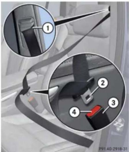
text_image
Car seatbelt diagram showing four numbered components of a car seatbelt buckle assembly① Seat belt outlet
② Latch plate
③ Buckle
④ Seat belt release button
▶ With a smooth motion, pull the seat belt out of seat belt outlet ①.
▶ Place the shoulder portion of the seat belt across the top of your shoulder and the lap portion across your hips.
▶ Push latch plate ② into buckle ③ until it clicks.
▶ If necessary, adjust the seat belt to the correct height.
▶ If necessary, tighten the lap portion to a snug fit by pulling shoulder portion up.
Seat belt outlet height adjustment
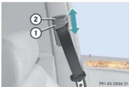
text_image
① ② P91.40-2846-31① Seat belt height adjuster
② Release button
▶ Raising: Slide seat belt height adjuster ① upward.
Seat belt height adjuster ① engages in different positions.
▶ Lowering: Press and hold release button ②.
▶ Slide seat belt height adjuster ① downward.
▶ Release button ② and make sure seat belt height adjuster ① engages into place.
Releasing the seat belts
▶ Press seat belt release button ④ (▶ page 63).
Allow the retractor to completely rewind the seat belt by guiding the latch plate ② (> page 63).
! Make sure the seat belt retracts fully so that the seat belt and/or latch plate cannot get caught or pinched in the door or in the seat mechanism. This can damage the seat belt and impair its effectiveness, and/or cause damage to the door and/or door trim panel. Such damage is not covered by the Mercedes-Benz Limited Warranty.
Damaged seat belts must be replaced. Contact an authorized Mercedes-Benz Center.
Safety and security
Occupant safety
Enhanced seat belt reminder system
When the engine is started, the seat belt telltale will always illuminate for 6 seconds to remind you and your passengers to fasten your seat belts.
If the driver's seat belt is not fastened when the engine is started, an additional warning chime will also sound for a maximum of 6 seconds or until the driver's seat belt is fastened.
If after these 6 seconds the driver's or the front passenger's seat belt (with the front passenger seat occupied) is not fastened with front doors closed,
- the seat belt telltale ≈ remains illuminated for as long as either the driver's or front passenger's seat belt is not fastened.
- and if the vehicle speed once exceeds 15 mph (25 km/h), the seat belt telltale starts flashing and a warning chime sounds with increasing intensity for a maximum of 60 seconds or until the driver's and front passenger's seat belt are fastened.
If you and/or your passenger release the seat belt during driving, the seat belt
telltale 🙏 starts flashing and the warning chime sounds as described before. If the driver's or the front passenger's seat belt remains unfastened after 60 seconds, the warning chime stops sounding, the seat belt telltale 🚏 stops flashing but continues to be illuminated.
After a vehicle standstill, the warning chime is reactivated and the seat belt telltale is flashing again if the vehicle speed once exceeds 15 mph (25 km/h).
The seat belt telltale will only go out if both the driver's and the front passenger's seat belt (with the front passenger seat occupied) are fastened, or the vehicle is standing still and a front door is opened. For more information, see "Practical hints" (▷ page 374).
Emergency Tensioning Device (ETD), seat belt force limiter
The seat belts for the front seats and second row outer seats are equipped with ETDs and seat belt force limiters. The seat belts for the third-row seats are equipped with ETDs.
The ETDs are designed to activate in the following cases:
- in frontal or rear-end impacts exceeding the system's preset deployment threshold
- in side impacts exceeding the system's preset deployment threshold on the far side of the impact
• in certain vehicle rollovers - if the restraint systems are operational and functioning correctly, see SRS indicator lamp (▷ page 47)
The ETDs for the front seats will only activate if the front seat belts are fastened (latch plate properly inserted into buckle).
The ETDs for the rear outer seats (second-row seats) or rear seats (third-row seats) will activate with or without the respective seat belts fastened.
In an impact, the ETDs remove slack from the seat belts in such a way that the seat belts fit more snugly against the body. Seat belt force limiters, when activated, are employed to help reduce the peak force exerted by the seat belts on occupants during a crash.
The ETDs do not correct an incorrect seat position or incorrectly worn seat belts.
Safety and security
Occupant safety
The ETDs do not pull occupants back toward the seat backrest.

Warning!
Pyrotechnic ETDs that were activated must be replaced.
For your safety, when disposing of the pyrotechnic ETDs always follow our safety instructions. These are available at any authorized Mercedes-Benz Center.
PRE-SAFE ^® has electrically operated reversible pre-tensioners that do not require replacement after activation.
Preventive occupant safety (PRE-SAFE®)

Warning!
PRE-SAFE ^® is intended to reduce the effects of an accident on vehicle occupants who are wearing their seat belt properly. Despite having the PRE-SAFE ^® system in your vehicle, the possibility of injuries occurring as a result of an accident cannot be eliminated. Therefore, you should always drive carefully and adjust your driving to the prevailing road, weather, and traffic conditions.
Your vehicle takes preventive measures to better protect the occupants in the following hazardous situations automatically.
PRE-SAFE ^® takes action in
• emergency braking maneuvers with the Brake Assist System (BAS) (▷ page 77) activated
- critical dynamic driving situations, e.g. when the vehicle is understeering or oversteering because it has exceeded its physical limitations
When you are driving faster than 22 mph (35 km/h), PRE-SAFE ^® takes the following measures in such situations:
- The front seat belts are pre-tensioned automatically.
- Vehicles with front passenger seat memory function: If the passenger seat is in an unfavorable position, it will be adjusted to a better position.
- If the vehicle is in a severe skid or is spinning, the door windows close until only a small gap remains.
- Vehicles with power tilt/sliding sunroof: If the vehicle is in a severe skid or is spinning, the tilt/sliding sunroof also close until only a small gap remains.
If the closing procedure of the door windows or tilt/sliding sunroof is blocked, the door windows or tilt/sliding sunroof will stop and open slightly.
Once the hazardous situation is over without an accident occurring, the seat belt pretensioning is deactivated. You can readjust all of the settings made by PRE-SAFE®.
If the seat belts do not release:
▶ Adjust the seat backrest or seat slightly to the rear until the seat belt tension is diminished.
The locking mechanism releases.
When moving the seats, make sure there are no items in the footwell or behind the seats. Otherwise, you could damage the seats.
Safety and security
Occupant safety
Active head restraints
The active head restraints are intended to offer the driver and front passenger increased protection from whiplash-type injuries. In the event of a rear-end collision, the active head restraints on the driver's and front passenger's seat are designed to move forward in the direction of travel, providing the head with increased support earlier on in the collision sequence. The active head restraints move forward whether the seat is occupied or not.

Warning!
Do not attach any objects (e.g. hangers) to the head restraint posts. Otherwise, the active head restraints may not be able to function properly or offer the intended degree of protection they were designed for in the event of a rear-end collision.
If the active head restraints have been triggered in an accident, the active head restraints must be reset. Otherwise, the active head restraints cannot offer any additional protection in the event of another rear-end collision.
For information on resetting the activated active head restraints, see “Resetting activated head restraints” (▷ page 385).
You cannot remove the active head restraint on the driver's and front passenger's seats.

Warning!
Only use seat or head restraint covers which have been tested and approved by Mercedes-Benz for your vehicle model.
Using other seat or head restraint covers may interfere with or prevent the activation of the active head restraints and/or the deployment of the front side impact air bags.
Contact an authorized Mercedes-Benz Center for availability.

Warning!
For your protection, drive only with properly positioned head restraints.
Adjust the head restraint so that it is as close to the head as possible and the center of the head restraint supports the back of the head at eye level. This will reduce the potential for injury to the head and neck in the event of an accident or similar situation.
For information on head restraint adjustment, see "Head restraints" (▷ page 100).
Correct driver seat adjustment

Warning!
In order to avoid possible loss of vehicle control all seat, head restraint, steering wheel, and rear view mirror adjustments, as well as fastening of seat belts, must be done before the vehicle is put into motion.
Safety and security
Occupant safety
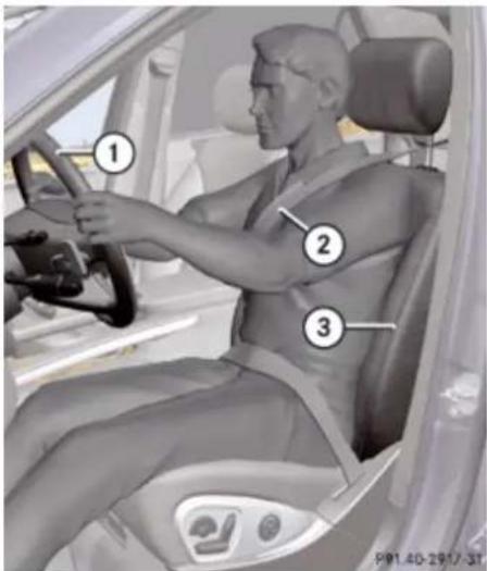
text_image
Diagram of a person in a car showing three labeled positions (1, 2, 3) on the steering wheel and dashboard.① Steering wheel
② Seat belt
③ Seat
▶ Position seat ③ (▷ page 98) and head restraint properly (▷ page 100).
⚠️ Observe Safety notes, see page 97.
Observe the following points:
• Always be in a properly seated position.
- The position should be as far rearward from the front air bag in steering wheel ① as possible, while still permitting proper operation of vehicle controls.
- Adjust seat ③ to a comfortable seating position that still allows you to reach the accelerator/brake pedal safely.
- Seat ③ must be adjusted so that you can correctly fasten and position your seat belt ②.
- The seat backrest must be in a position that is as nearly upright as possible.
- Adjust the seat cushion so that the front edge of the seat cushion lightly supports your legs.
- Adjust the head restraint so that it is as close to the head as possible and the center of the head restraint supports the back of the head at eye level.
- Never place hands under seat ③ or near any moving parts while seat ③ is being adjusted.
▶ Position steering wheel ① properly. See (▷ page 108) for manual adjustment and (▷ page 109) for electrical adjustment.
⚠️ Observe Safety notes, see page 108.
Make sure:
- You can reach steering wheel ① with your arms slightly bent at the elbows.
• You can move your legs freely. - All displays (including malfunction and indicator lamps) on the instrument cluster are clearly visible.
▶ Fasten and position your seat belt ② (▶ page 61) correctly.
⚠️ Observe Safety notes, see page 59.
Make sure:
- Seat belt ② is always fitted snugly.
- Adjust seat belt ② so that the shoulder section is located as close as possible to the middle of the shoulder.
- Place the lap portion of seat belt ② as low as possible on your hips.
Safety and security
Occupant safety
Children in the vehicle
Safety notes
If an infant or child is traveling with you in the vehicle:
- Secure the child using an infant or child restraint appropriate to the age and size of the child.
▶ Make sure the infant or child is properly secured at all times while the vehicle is in motion.
Warning!
When leaving the vehicle, always remove the SmartKey from the starter switch. Always take the SmartKey with you and lock the vehicle. Do not leave children unattended in the vehicle, even if they are secured in a child restraint system, or with access to an unlocked vehicle. A child's unsupervised access to a vehicle could result in an accident and/or serious personal injury. The children could
- injure themselves on parts of the vehicle
- be seriously or fatally injured through excessive exposure to extreme heat or cold
- injure themselves or cause an accident with vehicle equipment that can be operated even if the SmartKey is removed from the starter switch or removed from the vehicle, such as seat adjustment, steering wheel adjustment, or the memory function.
If children open a door, they could injure other persons or get out of the vehicle and injure themselves or be injured by following traffic.
Do not expose the child restraint system to direct sunlight. The child restraint system's metal parts, for example, could become very hot, and the child could be burned on these parts.
Warning!
Do not carry heavy or hard objects in the passenger or cargo compartment unless they are firmly secured in place.
Unsecured or improperly positioned cargo increases a child's risk of injury in the event of
• strong braking maneuvers
• sudden changes of direction
- an accident
For more information on loading, please refer to the "Loading and storing" (▷ page 227) chapter.
Infant and child restraint systems
⚠️ Observe Safety notes, see page 68.
We recommend all infants and children be properly restrained at all times while the vehicle is in motion.
Safety and security
Occupant safety
Canada only:
Only use a BabySmart ^TM compatible child restraint for the front passenger seat in this vehicle.
All lap/shoulder belts except the driver's seat belt have special seat belt retractors for secure fastening of child restraints.
To fasten a child restraint, follow child restraint instructions for mounting. Then pull the shoulder belt out completely and let it retract. During seat belt retraction, a ratcheting sound can be heard to indicate that the special seat belt retractor is activated. The seat belt is now locked. Push down on child restraint to take up any slack. To deactivate, release the seat belt buckle and let the seat belt retract completely. To deactivate the special seat belt retractor for the front passenger seat, the front passenger seat must be in the most backward position. The seat belt can again be used in the usual manner.

Warning!
Never release the seat belt buckle while the vehicle is in motion, since the special seat belt retractor will be deactivated.
i Information on child seats with mounting fittings for tether anchorages (▷ page 71).
For information on LATCH-type child seat anchors ( page 72).
The use of infant or child restraints is required by law in all 50 states, the District of Columbia, the U.S. territories and all Canadian provinces.
Infants and small children should be seated in an appropriate infant or child restraint system, properly secured in accordance with the manufacturer's instructions for the child restraint, that complies with U.S. Federal Motor Vehicle Safety Standards 213 and 225 and Canadian Motor Vehicle Safety Standards 213 and 210.2.
A statement by the child restraint manufacturer of compliance with these standards can be found on the instruction label on the restraint and in the instruction manual provided with the restraint.
When using any infant restraint, toddler restraint, or booster seat, make sure to carefully read and follow all manufacturer's instructions for installation and use.
Please read and observe warning labels affixed to the inside of the vehicle and to infant or child restraints.

Warning!
According to accident statistics, children are safer when properly restrained in the rear seating positions than in the front seating position. Thus, we strongly recommend that children be placed in the rear seats whenever possible. Regardless of seating position, children 12 years old and under must be seated and properly secured in an appropriate infant restraint, toddler restraint, or booster seat recommended for the size and weight of the child.
The infant or child restraint must be properly secured with the vehicle's seat belt, the seat belt and top tether strap, or lower anchors and top tether strap, fully in accordance with the child seat manufacturer's instructions.
Occupants, especially children, should always sit as upright as possible, wear the seat belt properly and use an appropriately sized infant restraint, toddler restraint, or booster seat recommended for the size and weight of the child.
Safety and security
Occupant safety
Children can be killed or seriously injured by an inflating air bag. Note the following important information when circumstances require you to place a child in the front passenger seat:
- USA only: Your vehicle is equipped with air bag technology designed to deactivate the front passenger front air bag in your vehicle when the system senses the weight of a typical 12-month-old child or less along with the weight of a standard appropriate child restraint on the front passenger seat.
• USA only: For children larger than the typical 12-month-old child, the front passenger front air bag may or may not be activated. Always make sure the
PASS AIR BAG OFF indicator lamp is illuminated, indicating that the front passenger front air bag is deactivated.
- Canada only: Children 12 years old and under must never ride in the front seat, except in a Mercedes-Benz authorized BabySmart™ compatible child seat, which operates with the BabySmart™ system installed in the vehicle to deactivate the front passenger front air bag when it is installed properly.
Otherwise they will be struck by the air bag when it inflates in a crash. If this happens, serious or fatal injury will result.
- A child in a rear-facing child restraint on the front passenger seat will be seriously injured or even killed if the front passenger front air bag inflates in a collision which could occur under some circumstances, even with the air bag technology installed in your vehicle. The only means to completely eliminate this risk is to never place a child in a rear-facing child restraint in the front seat. We therefore strongly recommend that you always place a child in a rear-facing child restraint in a backseat.
- If you must install a rear-facing child restraint on the front passenger seat because circumstances require you to do so, make sure the PASS AIR BAG OFF indicator lamp is illuminated, indicating that the front passenger front air bag is deactivated. Should the PASS AIR BAG OFF indicator lamp not illuminate or go out while the restraint is installed, please check installation. Periodically check the PASS AIR BAG OFF indicator lamp while
driving to make sure the
PASS AIR BAG OFF indicator lamp is
illuminated. If the ✗/2 PASS AIR BAG OFF
indicator lamp goes out or remains out, do not transport a child on the front passenger seat until the system has been repaired.
A child in a rear-facing child restraint on the front passenger seat will be seriously injured or even killed if the front passenger front air bag inflates.
- If you have to place a child in a forward-facing child restraint on the front passenger seat, move the seat as far back as possible, use the proper child restraint recommended for the age, size and weight of the child, and secure child restraint with the vehicle's seat belt according to the child seat manufacturer's instructions.
Warning!
Infants and small children should never share a seat belt with another occupant. During an accident, they could be crushed between the occupant and seat belt.
A child's risk of serious or fatal injuries is significantly increased if the child restraints
Safety and security
Occupant safety
are not properly secured in the vehicle and/or the child is not properly secured in the child restraint.
Children too big for a toddler restraint must ride in seats using regular seat belts.
Position shoulder belt across chest and shoulder, not face or neck. A booster seat may be necessary to achieve proper seat belt positioning for children over 41 lb (18 kg) until they reach a height where a lap/shoulder belt fits properly without a booster.
When the child restraint is not in use, remove it from the vehicle or secure it with the seat belt to prevent the child restraint from becoming a projectile in the event of an accident.
Installation of infant and child restraint systems

Warning!
Always lock the seat backrests in their upright position when the rear seats are occupied by passengers, after installing top tether straps, or the extended cargo compartment is not in use. Make sure that seat backrests are secured properly by
pushing and pulling on the seat backrests. If a seat backrest is not locked properly, the seat backrest could fold. The child seat would no longer be supported properly or positioned to provide its intended benefit. That could cause serious or even fatal injuries.
This vehicle is equipped with tether anchorages for a top tether strap at the second-row seat backrest. For installing an infant and child restraint system at the third-row seats, use the cargo tie-down rings in the cargo compartment (> page 234).
Top tether straps enable an additional connection to be made between child restraint systems secured with LATCH-type anchors and rear seats. This can further reduce the risk of injury.

Observe Safety notes, see page 68.
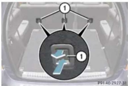
text_image
① ① P91 40-2927-31① Anchorage ring covers
▶ Press in lower part of anchorage ring cover ① on the seat backrest on which a child seat is to be installed.
▶ Pull on upper part of anchorage ring cover ① to remove cover.
▶ Store anchorage ring cover ① in a convenient place (e.g. glove box).
Safety and security
Occupant safety
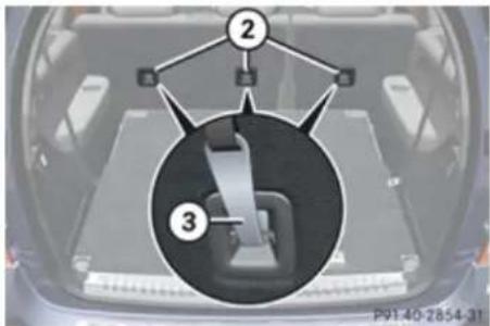
text_image
② ③ P9140-2854-31② Anchorage rings
③ Hook
▶ Move the respective head restraint to its uppermost position (▷ page 104).
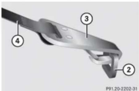
text_image
P91.20-2202-31② Anchorage ring
③ Hook
④ Top tether strap
▶ Guide top tether strap ④ between head restraint and top of the seat backrest.
▶ Securely fasten hook ③, which is part of top tether strap ④, to anchorage ring ②.
Make sure
- top tether strap ④ is not twisted
• the head restraint is installed and positioned such that the top tether strap can pass freely between the head restraint and top of the seat backrest
• the top tether strap is positioned between the seat backrest and the cargo compartment cover blind (if installed) - the top tether strap is positioned between the seat backrest and the cargo net (if installed)
For safety, make sure hook ③ is attached to anchorage ring ② beyond the safety catch, as illustrated.
▶ Lower the head restraint if necessary (▷ page 104).
Make sure the top tether strap can pass freely between the head restraint and top of the seat backrest.
Install the child restraint system and tighten the top tether strap according to the child restraint manufacturer's instructions.
After removing the child restraint system and the top tether strap ④.
▶ Reinstall the anchorage ring cover ①.
Child seat anchors - LATCH-type
This vehicle is equipped with two LATCH-type anchors (at each of the outboard second-row seats and third-row seats) for the installation of a LATCH-type child seat with matching mounting fittings.

Observe Safety notes, see page 68.

Warning!
Children too big for a toddler restraint must ride in seats using regular seat belts. Position shoulder belt across chest and shoulder, not face or neck.
Safety and security
Occupant safety
A booster seat may be necessary to achieve proper seat belt positioning for children over 41 lb (18 kg) until they reach a height where a lap/shoulder belt fits properly without a booster.
Install child seat according to manufacturer's instructions.
The child seat must be firmly attached to the right and left side anchors.
An incorrectly mounted child seat may come loose during an accident which could result in serious injury or death to the child. Damaged or impact damaged child seats or child seat mounting fittings must be replaced.
Non-LATCH-type child seats may also be used and can be installed using the vehicle's seat belt system. Install child seat according to the manufacturer's instructions.
The LATCH-type anchors are blended with covers.
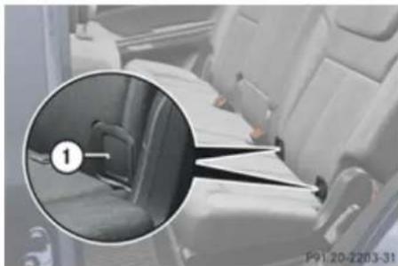
natural_image
Interior view of a car seatbelt with a magnified inset showing the seatbelt detail (no text or symbols visible)Example, second-row seats
① Anchorage ring covers
Remove anchorage ring covers ① from the seat on which a child seat is to be installed.
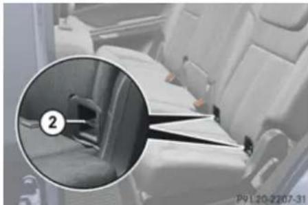
natural_image
Interior view of a car seatbelt with a magnified inset showing a numbered component (no text or symbols visible)Example, second-row seats
② Anchors
Install a LATCH-type child seat according to the manufacturer's instructions. A rigid connection between the child seat and the body of the vehicle is established.
! Make sure the seat belt for the center seat can operate freely with a child seat installed.
Child safety
Child safety locks

Observe Safety notes, see page 68.

Warning!
Children could open a rear door from the inside. This may cause serious personal injury or an accident. Therefore, secure the rear doors with the child safety locks whenever children are riding in the back seats of the vehicle.
The child safety locks on the rear doors enable you to secure each rear door individually. You cannot open a secured rear door from the inside. You can open the rear door from the outside when the vehicle is unlocked.
▶▶
Safety and security
Occupant safety
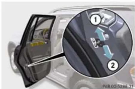
natural_image
Close-up of a car's front window and dashboard showing a close-up of the dashboard with directional arrows (no text or symbols visible)① Releasing
② Securing
▶ Securing: Press the lever down in direction of arrow ②.
▶ Check to make sure the child safety locks are working properly.
▶ Releasing: Press the lever up in direction of arrow ①.
Override switch
⚠️ Observe Safety notes, see page 68.
With the override switch you can disable the rear door window switches in the rear door panels.
Warning!
Activate the override switch when children are riding in the back seats of the vehicle. The children may otherwise injure themselves, e.g. by becoming trapped in the window opening.
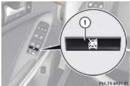
text_image
1 P54.25-8631-31① Override switch
▶ Activating: Press override switch ①. The switch engages in recessed position. The rear door windows can no longer be operated using the respective switch located in the rear doors.
It is still possible to operate the rear door windows using the switches located on the door control panel of the driver's door.
▶ Deactivating: Press override switch ① again.
The switch disengages from its recessed position back to its original position.
The rear door windows can again be operated using the respective switch located in the rear doors.
For more information on power windows, see the "Controls in detail" section (▷ page 124).
Safety and security
Driving safety systems
Panic alarm
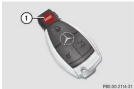
text_image
① P80.00-2114-31① PANIC button
i USA only:
This device complies with Part 15 of the FCC Rules. Operation is subject to the following two conditions:
- This device may not cause harmful interference, and
- this device must accept any interference received, including interference that may cause undesired operation.
Any unauthorized modification to this device could void the user's authority to operate the equipment.
Canada only:
This device complies with RSS-210 of Industry Canada. Operation is subject to the following two conditions:
- This device may not cause interference, and
- this device must accept any interference received, including interference that may cause undesired operation of the device.
Any unauthorized modification to this device could void the user's authority to operate the equipment.
▶ Activating: Press and hold button ① for at least 1 second.
An audible alarm and flashing exterior lamps will operate briefly.
▶ Deactivating: Press button ① again.
or
▶ Insert the SmartKey in the starter switch.
or
▶ Press the KEYLESS-GO start/stop button. The SmartKey with KEYLESS-GO must be inside the vehicle.
Driving safety systems
Introduction
This section contains information about the following driving safety systems:
• ABS (Antilock Brake System)
• BAS (Brake Assist System)
• EBP (Electronic Brake Proportioning)
- ESP® (Electronic Stability Program)
In winter operation, the maximum effectiveness of most of the driving systems described in this section is only achieved with winter tires, or snow chains as required.
Safety notes
Warning!
The following factors increase the risk of accidents:
• Excessive speed, especially in turns
• Wet and slippery road surfaces
• Following another vehicle too closely
The driving safety systems described in this section cannot reduce these risks or
Safety and security
Driving safety systems
prevent the natural laws of physics from acting on the vehicle. They cannot increase braking or steering efficiency beyond that afforded by the condition of the vehicle brakes and tires or the traction afforded.
Only a safe, attentive, and skillful driver can prevent accidents.
The capabilities of a vehicle equipped with the driving safety systems described in this section must never be exploited in a reckless or dangerous manner which could jeopardize the user's safety or the safety of others.
Always adjust your driving style to the prevailing road and weather conditions and keep a safe distance to other road users and objects on the street.
If a driving system malfunctions, other driving safety systems may also switch off. Observe indicator and warning lamps that may come on as well as messages in the multifunction display that may appear.
ABS
⚠️ Observe Safety notes, see page 75.
Warning!
Do not pump the brake pedal. Use firm, steady brake pedal pressure instead. Pumping the brake pedal defeats the purpose of the ABS and significantly reduces braking effectiveness.
The Antilock Brake System (ABS) regulates the brake pressure so that the wheels do not lock during braking. This allows you to maintain the ability to steer your vehicle.
The ABS is functional above a speed of approximately 5 mph (8 km/h) independent of road surface conditions.
On slippery road surfaces, the ABS will respond even to light brake pressure.
The indicator lamp in the instrument cluster comes on when you switch on the ignition. It goes out when the engine is running.
Braking
At the instant one of the wheels is about to lock up, a slight pulsation can be felt in the brake pedal, indicating that the ABS is in the regulating mode.
▶ Keep firm and steady pressure on the brake pedal while you feel the pulsation.
Continuous, steady brake pedal pressure yields the advantages provided by the ABS, namely braking power and the ability to steer the vehicle.
The pulsating brake pedal can be an indication of hazardous road conditions and functions as a reminder to take extra care while driving.
Emergency brake maneuver
- Keep continuous full pressure on the brake pedal.
Warning!
If the ABS malfunctions, other driving safety systems such as the BAS or the ESP® are also switched off. Observe indicator and warning lamps that may come on as well as messages in the multifunction display that may appear.
If the ABS malfunctions, the wheels may lock during hard braking, reducing steering capability and extending the braking distance.
Safety and security
Driving safety systems
For more information, see "What to do if ...?" (▷ page 371).
Off-road ABS
With the off-road driving program switched on, or with the transmission in LOW RANGE, mode the ABS is designed for off-road is automatically activated.
When applying the brakes at speeds below 18 mph (30 km/h), the front wheels are locked cyclically to shorten the braking distance (dig-in effect). This effects steering the vehicle.
BAS

Observe Safety notes, see page 75.
The Brake Assist System (BAS) operates in emergency situations. If you apply the brakes very quickly, the BAS automatically provides full brake boost, thereby potentially reducing the braking distance.
▶ Apply continuous full braking pressure until the emergency braking situation is over. The ABS will prevent the wheels from locking.
When you release the brake pedal, the brakes function again as normal. The BAS is then deactivated.

Warning!
If the BAS malfunctions, the brake system still functions, but without the additional brake boost available that the BAS would normally provide in an emergency braking maneuver. Therefore, the braking distance may increase.
EBP

Observe Safety notes, see page 75.
The Electronic Brake Proportioning (EBP) enhances braking effectiveness by allowing the rear brakes to supply a greater proportion of the braking effort in straight line braking without a loss of vehicle stability.

Warning!
If the EBP malfunctions, the brake system will still function with full brake boost. However, the rear wheels could lock up during emergency braking situations, for example. You could lose control of the vehicle and cause an accident.
Adapt your driving style to the changed driving characteristics.
ESP®

Observe Safety notes, see page 75.
The Electronic Stability Program (ESP ^® ) is operational as soon as the engine is running and monitors the vehicle's traction (force of adhesive friction between the tires and the road surface) and handling.
The ESP ^® recognizes when a wheel is spinning or if the vehicle starts to skid. By applying brakes to individual wheels and by limiting the engine output, the ESP ^® works to stabilize the vehicle. The ESP ^® is especially useful while driving off and on wet or slippery road surfaces. The ESP ^® also stabilizes the vehicle during braking and steering maneuvers.
The ESP® warning lamp ⚠️ in the instrument cluster comes on when you switch on the ignition. It goes out when the engine is running.
▶▶
Safety and security
Driving safety systems
The ESP® warning lamp in the instrument cluster flashes when the ESP® is engaged.

Warning!
Never switch off the ESP ^® when you see the ESP ^® warning lamp ⚠️ flashing in the instrument cluster. In this case proceed as follows:
- When driving off, apply as little throttle as possible.
- While driving, ease up on the accelerator pedal.
- Adapt your speed and driving style to the prevailing road conditions.
Failure to observe these guidelines could cause the vehicle to skid. The ESP ^® cannot prevent accidents resulting from excessive speed.
! Only conduct operational or performance tests on a two-axle dynamometer. If such tests are necessary, contact an authorized Mercedes-Benz Center. You could otherwise seriously damage the brake system or the transfer case which is not covered by the Mercedes-Benz Limited Warranty.
Because the ESP® operates automatically, the engine and ignition must be shut off (SmartKey in starter switch position 0 or 1 or KEYLESS-GO start/stop button in position 0 or 1) when the parking brake is being tested on a brake test dynamometer. Such testing should be no longer than 10 seconds.
Active braking action through the ESP ^® may otherwise seriously damage the brake system which is not covered by the Mercedes-Benz Limited Warranty.
! The ESP® will only function properly if you use wheels of the recommended tire size as specified in the "Technical data" section of this Operator's Manual.
i The Distronic system and cruise control switch off automatically when the ESP® engages.
For more information, see the "Practical hints" section (▷ page 332) and (▷ page 376).
Electronic Traction System (4-ETS)

Observe Safety notes, see page 75.
The 4-ETS (four-wheel Electronic Traction System) are components of the ESP®. The 4-ETS improves the vehicle's ability to utilize available traction, especially under slippery road conditions by applying the brakes to a spinning wheel. In addition, more power is transferred to the wheel(s) with traction.
When you switch off the ESP®, the 4-ETS is still enabled.
If conditions require, switch on the off-road driving program (▷ page 185) or the LOW RANGE mode (▷ page 141).
Off-road 4-ETS
With the off-road driving program switched on (▷ page 185), or the transmission in LOW RANGE mode (▷ page 142), the 4-ETS designed for off-road use is activated automatically.
Safety and security
Driving safety systems
Switching off the ESP®

Warning!
The ESP ^® should not be switched off during normal driving other than in the circumstances described below. Disabling the system will reduce vehicle stability in driving maneuvers.
Do not switch off the ESP ^® when a spare wheel is mounted.
To improve the vehicle's traction, switch off the ESP® in driving situations in which it would be advantageous to have the drive wheels spin and thus cut into surfaces for better grip such as:
- when driving with snow chains
- in deep snow
- in sand or gravel

Warning!
Switch on the ESP ^® immediately if the aforementioned circumstances do not apply anymore. Otherwise the ESP ^® will not stabilize the vehicle when it is starting to skid or a wheel is spinning.
When you switch off the ESP®
- the ESP ^ does not stabilize the vehicle
- the engine output is not limited, which allows the drive wheels to spin and thus cut into surfaces for better grip
- the 4-ETS will still apply the brakes to a spinning wheel
- the ESP® continues to operate when you are braking
- you cannot activate the cruise control or the Distronic system
- the cruise control or the Distronic system switch off if activated
When the ESP ^ is switched off and one or more drive wheels are spinning, the ESP ^ warning lamp ⚠️ in the instrument cluster flashes. However, the ESP ^ will then not stabilize the vehicle.
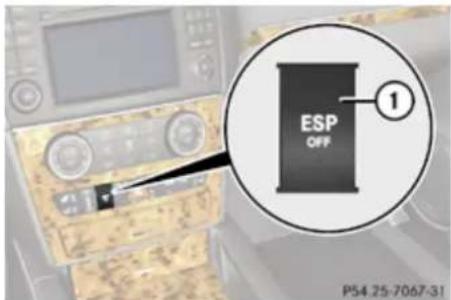
text_image
ESP OFF ① P54.25-7067-31① ESP® switch
With the engine running, press ESP ^ switch ① until the ESP ^ warning lamp ⚠️ in the instrument cluster comes on. The ESP ^ is switched off.

Warning!
When the ESP ^® warning lamp is illuminated continuously, the ESP ^® is switched off or is not operational due to a malfunction. Vehicle stability in standard driving maneuvers is reduced.
Adapt your speed and driving to the prevailing road conditions and to the non-operating status of the ESP ^® .
Safety and security
Anti-theft systems
! Avoid spinning of a drive wheel for an extended period with the ESP® switched off. This may cause serious damage to the drivetrain which is not covered by the Mercedes-Benz Limited Warranty.
Switching on the ESP®
Press ESP® switch ① until the ESP® warning lamp in the instrument cluster goes out. You are now again in normal driving mode with the ESP® switched on.
Off-road ESP®
With the off-road driving program switched on ( page 185), or with the transmission in LOW RANGE mode ( page 142), the ESP ^® designed for off-road use is automatically activated. At speeds below 27 mph (45 km/h), the ESP ^® assists in over-/understeering, thus improving vehicle traction.
ESP® trailer stabilization
If the trailer you are towing should begin to sway, the rig can only be stabilized by
immediately applying the brakes hard. Steering during this maneuver will not help to stabilize the rig.
The ESP ^ will assist you in such situations. The ESP ^ recognizes when the trailer starts swaying and will apply the brakes to reduce the vehicle speed to a non-critical speed that allows the vehicle-trailer combination to stabilize.
The ESP ^® trailer stabilization is functional at vehicle speeds above approximately 40 mph (65 km/h) when the ESP ^® is switched on.
Warning!
The system will not be able to assist when the trailer jackknifes
- if the ESP ^ has switched off due to a malfunction
- on wet or icy roads
• on roads with slippery surface - in sand or gravel
Trailers with a high center of gravity may tip over before the system recognizes swaying of the trailer.
Anti-theft systems
Immobilizer
The immobilizer prevents unauthorized persons from starting your vehicle.
When leaving the vehicle, always take the SmartKey with you and lock the vehicle. The engine can be started by anyone with a valid SmartKey that is left inside the vehicle.
Activating
▶ With SmartKey: Remove the SmartKey from the starter switch.
With KEYLESS-GO: Turn off the engine and open the driver's door.
Deactivating
▶ Switch on the ignition.
Starting the engine will also deactivate the immobilizer. In the event that the engine cannot be started (yet the vehicle's battery is charged), the system is not operational. Contact an authorized Mercedes-Benz Center or call 1-800-FOR-MERCedes (in the USA), or 1-800-387-0100 (in Canada).
Safety and security
Anti-theft systems
Anti-theft alarm system
Once the alarm system has been armed, a visual and audible alarm is triggered when someone opens:
- a door
- the tailgate
- the hood
The alarm will stay on even if the activating element (a door, for example) is immediately closed.
The alarm system will also be triggered when
- the vehicle is opened with the mechanical key
• a door is opened from the inside
To cancel the alarm after it has been triggered, see "Canceling the alarm" (▷ page 81).
If the alarm stays on for more than 30 seconds, a call to the Response Center is initiated automatically by the Tele Aid system provided that you have subscribed to the Tele Aid service and that it has been activated properly, and that the necessary mobile phone, power supply and GPS coverage are available.
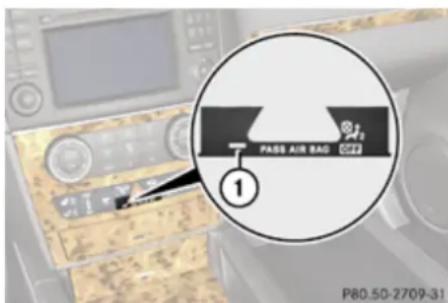
text_image
PASS AIR BAD ① P80.50-2709-31① Indicator lamp
▶ Arming: Lock the vehicle with the SmartKey or with KEYLESS-GO.
The turn signal lamps flash three times to indicate that the vehicle is locked. Indicator lamp ① flashes to indicate that the alarm system is armed.
If the turn signal lamps do not flash three times, a door or the tailgate may not be properly closed.
Close the respective element and lock the vehicle again.
▶ Disarming: Unlock the vehicle with the SmartKey or with KEYLESS-GO.
The turn signal lamps flash once to indicate that the alarm system is disarmed.
The vehicle will lock and the alarm system will rearm automatically again after approximately 40 seconds unless you open a door or the tailgate.
Canceling the alarm
To cancel the alarm, do one of the following:
▶ Insert the SmartKey in the starter switch.
▶ Press button 📁 or 🔒 on the SmartKey.
In vehicles with KEYLESS-GO:
▶ Grasp an outside door handle.
The SmartKey must be within 3 ft (1 m) of the vehicle.
▶ Press the KEYLESS-GO start/stop button. The SmartKey must be inside the vehicle.
Controls in detail
Vehicle equipment 84 Transfer case 141
Locking and unlocking 84 Differential locks (Canada only) ..... 144
Starter switch positions 95 Instrument cluster 147
Seats 97 Control system 148
Multifunction steering wheel 108 Driving systems 169
Mirrors 111 Overview of climate control sys-
Memory function 113 tem functions and air vents 199
Lighting 114 Climate control 202
Wipers 122 3-zone automatic climate control ... 210
Power windows 124 Rear window defroster 223
Driving and parking 128 Power tilt/sliding sunroof 224
Automatic transmission 135 Loading and storing 227
Useful features 245
Controls in detail
Locking and unlocking
Vehicle equipment
This Operator's Manual describes all features, standard or optional, potentially available for your vehicle at the time of purchase. Please be aware that your vehicle might not be equipped with all features described in this manual.
Locking and unlocking
Notes
⚠️ Observe Safety notes, see page 68.
When unlocking the vehicle, all turn signal lamps flash once, the locking knobs in the doors move up, and the anti-theft alarm system is disarmed.
When locking the vehicle, all turn signal lamps flash three times, the locking knobs in the doors move down, and the anti-theft alarm system is armed.
All doors and the tailgate must be closed.
! If you cannot lock or unlock the vehicle with the SmartKey, the batteries in the SmartKey are discharged, the SmartKey is malfunctioning, or the vehicle battery is drained.
- Check the batteries in the SmartKey and replace them if necessary.
-
Use the mechanical key to unlock the driver's door.
-
Use the mechanical key to lock the vehicle.
- Have the vehicle battery and the vehicle battery connections checked at an authorized Mercedes-Benz Center.
If the SmartKey is malfunctioning, contact Roadside Assistance or an authorized Mercedes-Benz Center.
SmartKey
Your vehicle comes supplied with two SmartKeys, each with remote control and a removable mechanical key.
The SmartKey centrally locks and unlocks:
- the doors
- the tailgate
- the fuel filler flap
Controls in detail
Locking and unlocking
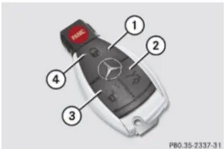
text_image
P80.35-2337-31① Lock button
② Unlock button for tailgate
③ Unlock button
④ Battery check lamp
i USA only:
This device complies with Part 15 of the FCC Rules. Operation is subject to the following two conditions:
- This device may not cause harmful interference, and
- this device must accept any interference received, including interference that may cause undesired operation.
Any unauthorized modification to this device could void the user's authority to operate the equipment.
Canada only:
This device complies with RSS-210 of Industry Canada. Operation is subject to the following two conditions:
- This device may not cause interference, and
- this device must accept any interference received, including interference that may cause undesired operation of the device.
Any unauthorized modification to this device could void the user's authority to operate the equipment.
Factory setting
▶ Global unlocking: Press button
The vehicle will lock again automatically and rearm the anti-theft alarm system within approximately 40 seconds of unlocking if neither door nor tailgate is opened.
Global locking: Press button
Selective setting
If you frequently travel alone, you may wish to reprogramm the SmartKey so that pressing
button ☑ only unlocks the driver's door and the fuel filler flap.
Switching on/off: Press and hold buttons and simultaneously for approximately 5 seconds until battery check lamp ④ (▶ page 85) flashes twice.
The SmartKey will then function as follows:
Unlocking driver's door and fuel filler flap: Press button once.
▶ Global unlocking: Press button twice.
▶ Global locking: Press button 🔒.
KEYLESS-GO
Vehicles equipped with KEYLESS-GO come with two SmartKeys with KEYLESS-GO, each with remote control and a removable mechanical key.
The KEYLESS-GO function is integrated into the SmartKey. The validity of the SmartKey is checked every time you grasp an outside door handle.
▶▶
Controls in detail
Locking and unlocking
When the SmartKey is valid, your vehicle unlocks
- the doors
- the fuel filler flap
- the tailgate
i USA only:
This device complies with Part 15 of the FCC Rules. Operation is subject to the following two conditions:
- This device may not cause harmful interference, and
- this device must accept any interference received, including interference that may cause undesired operation.
Any unauthorized modification to this device could void the user's authority to operate the equipment.
Canada only:
This device complies with RSS-210 of Industry Canada. Operation is subject to the following two conditions:
-
This device may not cause interference, and
-
this device must accept any interference received, including interference that may cause undesired operation of the device.
Any unauthorized modification to this device could void the user's authority to operate the equipment.
Important notes on using KEYLESS-GO
- You can also use the SmartKey with KEYLESS-GO like a normal SmartKey (▷ page 84).
- You can combine KEYLESS-GO functions with normal SmartKey functions (e.g. unlocking with KEYLESS-GO and locking with button ).
• Always carry the SmartKey with you. -
Never store the SmartKey together with:
-
Electronic items such as a mobile phone or another SmartKey
- Metallic objects such as coins or metal foil
Doing so could impair the function of the KEYLESS-GO system.
- To lock or unlock the vehicle, the SmartKey must be located outside the vehicle within approximately 3 ft (1 m) of a door or the tailgate.
- If the vehicle has been parked for more than 72 hours, you must pull an outside door handle in order to activate the KEYLESS-GO function.
- If the SmartKey is positioned farther away from the vehicle, the system may no longer recognize the SmartKey. The vehicle cannot be locked or the engine started via the KEYLESS-GO system.
- If the SmartKey is removed from the vehicle (e.g. if a passenger exits the vehicle with the SmartKey)
- when pressing the KEYLESS-GO start/stop button or trying to lock the vehicle with the lock button on an outside door handle the message Key Not
Controls in detail
Locking and unlocking
Detected appears in the multifunction display
- with the engine running, the message Key Not Detected appears in the multifunction display while driving off
Find the SmartKey or change its present location immediately (e.g. place it on the front passenger seat or insert it in shirt pocket).
- If you have started the engine with the KEYLESS-GO start/stop button, you can turn it off again by
- pressing the KEYLESS-GO start/stop button
- inserting the SmartKey into the starter switch when the vehicle is at a standstill and the automatic transmission is in park position P
- The vehicle could be inadvertently unlocked if the SmartKey is within 3 ft (1 m) of the vehicle and
- an outside door handle is splashed with water
or
- you attempt to clean an outside door handle
- Remember that the engine can be started by anyone with a SmartKey that is left inside the vehicle.
Possibility 1 (One SmartKey in the vehicle, one SmartKey outside the vehicle): If you leave the SmartKey behind when exiting and locking the vehicle, no message appears in the multifunction display.
Possibility 2 (One SmartKey in the vehicle, no SmartKey outside the vehicle): When exiting and trying to lock the vehicle, the message Key Detected In Vehicle appears in the multifunction display. The vehicle will not be locked.
Factory setting
▶ Global unlocking: Grasp an outside door handle.
The vehicle will lock again automatically and rearm the anti-theft alarm system within approximately 40 seconds if neither door nor tailgate is opened.
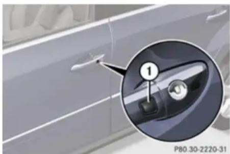
natural_image
Close-up of a car door panel with a close-up inset showing the handle (no text or symbols visible)① Lock button on the outside door handle
▶ Global locking: Press lock button ① on an outside door handle.
Selective setting
If you frequently travel alone, you may wish to reprogram the SmartKey so when you grasp the driver's outside door handle, only the driver's door and the fuel filler flap unlock.
▶ Switching on/off: Press and hold buttons
and simultaneously for approximately 5 seconds until battery check lamp ④ (▶ page 85) flashes twice.
The SmartKey will then function as follows:
Controls in detail
Locking and unlocking
- Unlocking driver's door and fuel filler flap: Grasp the driver's outside door handle.
Global unlocking: Grasp any outside door handle other than the driver's outside door handle.
▶ Global locking: Press lock button ① on an outside door handle.
Checking SmartKey batteries
▶ Press button 🔒 or 🔒 on the SmartKey.
Battery check lamp ④ (▷ page 85) comes on briefly to indicate that the SmartKey batteries are in order.
If the battery check lamp does not come on briefly during check, the SmartKey batteries are discharged.
▶ Replace the batteries (▷ page 386).
You can obtain the required batteries at any authorized Mercedes-Benz Center.
If the batteries are checked within signal range of the vehicle, pressing button or will lock or unlock the vehicle accordingly.
Loss of the SmartKey
If you lose your SmartKey or mechanical key, you should do the following:
▶ Have the SmartKey deactivated by an authorized Mercedes-Benz Center.
▶ Report the loss of the SmartKey or the mechanical key to your car insurance company immediately.
▶ Have the mechanical lock replaced if necessary.
Any authorized Mercedes-Benz Center will be glad to supply you with a replacement.
Opening the doors from the inside
You can open a locked door from the inside. Open door only when conditions are safe to do so.
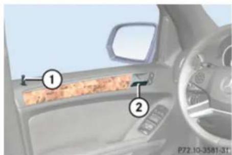
text_image
Car interior panel with numbered annotations pointing to a textured orange stripe and a blue stripe, likely indicating parts of a vehicle or dashboard.① Locking knob
② Inside door handle
If the vehicle has previously been locked with the SmartKey or with KEYLESS-GO, opening a door from the inside will trigger the anti-theft alarm system.
To cancel the alarm, see (▷ page 81).
▶ Front doors: Pull on inside door handle ② on the respective front door to open door.
If the door was locked, locking knob ① will move up.
▶ Rear doors: Pull up locking knob ① on the respective rear door to unlock door.
▶ Pull on inside door handle ② on the respective rear door to open door.
Controls in detail
Locking and unlocking
Automatic central locking
The doors and the tailgate lock automatically when the vehicle is set into motion.
You can open a locked door from the inside. Open door only when conditions are safe to do so.
The doors are designed to unlock automatically after an accident if the force of the impact exceeds a preset threshold.
The vehicle locks automatically when the ignition is switched on and the wheels are turning at vehicle speeds of approximately 9 mph (15 km/h) or more. You could therefore lock yourself out when the vehicle is pushed or towed or is on a test stand.
You can deactivate the automatic central locking using the control system (▷ page 163).
Locking and unlocking from the inside
⚠️ Observe Safety notes, see page 68.
You can lock or unlock the vehicle from inside using the central locking switches. This can be useful, for example, if you want to lock the vehicle before starting to drive.
The central locking switches do not lock or unlock the fuel filler flap.
The switches are located in each front door.
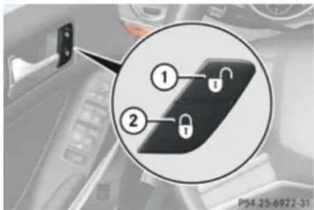
text_image
① ② P54-25-6922-31① Central unlocking switch
② Central locking switch
▶ Locking: Press central locking switch ②. If all doors and the tailgate are closed, the vehicle locks.
▶ Unlocking: Press central unlocking switch ①.
You can open a locked door from inside at any time. Open door only when conditions are safe to do so.
If the vehicle was previously locked with the central locking switch:
• and the SmartKey is set to factory settings, the complete vehicle is unlocked when a front door is opened from the inside
• and the SmartKey is set to selective settings, only the front door opened from the inside is unlocked
If the vehicle was previously locked centrally with the SmartKey or with KEYLESS-GO, it will not unlock using the central unlocking switch.
Controls in detail
Locking and unlocking
Tailgate

Warning!
Make sure the tailgate is closed when the engine is running and while driving. Among other dangers, deadly carbon monoxide (CO) gases may enter vehicle interior resulting in unconsciousness and death.
A minimum height clearance of 7.40 ft (2.25 m) is required to open the tailgate.
Opening the tailgate from the outside
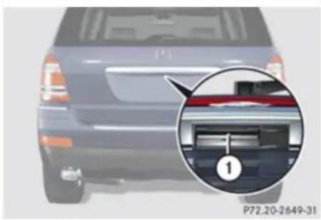
natural_image
Side view of a car's rear bumper with a close-up inset showing internal components (no text or symbols)① Handle
▶ Pull on handle ①.
In vehicles without KEYLESS-GO: The vehicle must be unlocked.
▶ Pull tailgate upwards to open.
Closing the tailgate from the outside

Warning!
To prevent possible personal injury, always keep hands and fingers away from the cargo compartment opening when closing the tailgate. Be especially careful when small children are around.
When leaving the vehicle, always remove the SmartKey from the starter switch, take it with you, and lock the vehicle. Do not leave children unattended in the vehicle, or with access to an unlocked vehicle. A child's unsupervised access to a vehicle could result in an accident and/or serious personal injury.
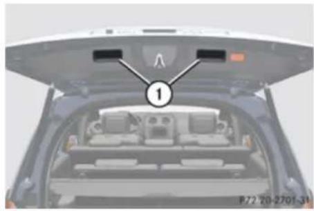
natural_image
Top-down view of a car cab with visible seats and dashboard, no text or symbols present① Handles
▶ Lower tailgate by pulling firmly on handles ①.
▶ Close tailgate with hands placed flat on it. Once the tailgate touches the latch, the tailgate will pull itself shut automatically.
Opening the tailgate from the inside with handle

Warning!
Do not leave children unattended in the vehicle. Children could open the tailgate from the inside, which could result in an accident and/or serious personal injury.
Controls in detail
Locking and unlocking
! Always make sure there is sufficient overhead clearance.
You can unlock the tailgate from the third-row seats and then open it manually.
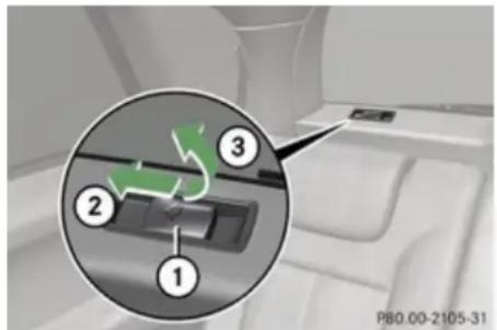
text_image
1 2 3 P80.00-2105-31① Handle
② Push
③ Lift
▶ Push handle ① in direction of arrow ② and hold it there.
▶ From this position, lift handle ① in direction of arrow ③ and hold it there. The tailgate is released and can be opened manually.
If you do not open the tailgate within a few seconds, the tailgate lock will engage again automatically. Additionally, the tailgate will
relock automatically if the vehicle was locked when the tailgate was released from the inside.
If the tailgate lock does not engage automatically and, if applicable, the tailgate does not relock after a few seconds, you have to close the tailgate manually (▷ page 90).
Power tailgate
Warning!
Make sure the tailgate is closed when the engine is running and while driving. Among other dangers, deadly carbon monoxide (CO) gases may enter vehicle interior resulting in unconsciousness and death.
! The tailgate swings open upwards automatically. Always make sure there is sufficient overhead clearance.
A minimum height clearance of 7.40 ft (2.25 m) is required to open the tailgate.
In vehicles with power tailgate, you can
- open and close the tailgate from the inside and the outside electrically
- limit the opening height of the tailgate
-
interrupt the opening/closing procedure at any time by
-
pressing or pulling the door-mounted remote tailgate switch
- pressing button ➕ on the SmartKey
- pressing the tailgate closing switch
- pressing the KEYLESS-GO locking/closing switch
Depending on production date, an acoustic warning sounds when opening or closing the tailgate.
Opening the tailgate from the outside
You can unlock and open the tailgate simultaneously from the outside when the vehicle is stationary.
Controls in detail
Locking and unlocking
▶ Press and hold button 📋 on the SmartKey until the tailgate unlocks and begins to open.
While the tailgate is opening, an acoustic warning sounds.
or
▶ Vehicles with KEYLESS-GO: Pull on the handle (> page 90).
The tailgate is unlocked and opens.
Depending on production date, an acoustic warning sounds while the tailgate opens.
Closing the tailgate from the outside

Observe Safety notes, see page 68.

Warning!
Monitor the closing procedure carefully to make sure no one is in danger of being injured. To prevent possible personal injury, always keep hands and fingers away from the cargo compartment opening when closing the tailgate. Be especially careful when small children are around. To stop the closing procedure, do one of the following:
- Press button 📋 on the SmartKey.
- Press or pull the remote tailgate opening/closing switch on the driver's door.
- Press the tailgate closing switch.
- Press the KEYLESS-GO locking/closing switch.
In vehicles with power tailgate you can close the tailgate separately from the outside using the tailgate closing switch or button 📋 on the SmartKey.
Do not leave the SmartKey in the vehicle. You may lock yourself out.
If the vehicle was previously centrally locked with the SmartKey or KEYLESS-GO, the tailgate will lock automatically after closing it. The turn signal lamps flash three times to confirm locking.
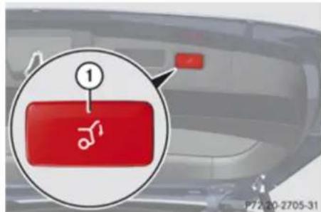
text_image
① P72-20-2705-31Vehicles without KEYLESS-GO
① Tailgate closing switch
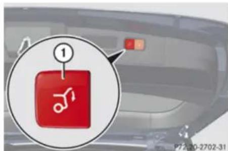
text_image
1 P72.20-2702-31Vehicles with KEYLESS-GO
① Tailgate closing switch
Controls in detail
Locking and unlocking
▶ Press tailgate closing switch ① briefly or press and hold button 📋 on the SmartKey.
The tailgate closes. Depending on production date, an acoustic warning sounds when the tailgate closes.
If the tailgate comes into contact with an object while closing (e.g. luggage that has been piled too high), the closing procedure is stopped and the tailgate reopens.
Closing the tailgate and locking the vehicle from the outside (vehicles with KEYLESS-GO)

Observe Safety notes, see page 68.

Warning!
Monitor the closing procedure carefully to make sure no one is in danger of being injured. To prevent possible personal injury, always keep hands and fingers away from the cargo compartment opening when closing the tailgate. Be especially careful when small children are around. To stop the closing procedure, do one of the following:
- Press button 📋 on the SmartKey.
- Press or pull the remote tailgate opening/closing switch on the driver's door.
- Press the tailgate closing switch.
- Press the KEYLESS-GO locking/closing switch.
In vehicles with power tailgate and KEYLESS-GO, you can close the tailgate and lock the vehicle simultaneously from the outside using the KEYLESS-GO locking/closing switch.
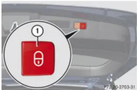
text_image
1 P72.20-2703-31① KEYLESS-GO locking/closing switch
▶ Make sure you have the SmartKey with you.
▶ Press KEYLESS-GO locking/closing switch
① briefly.
The tailgate closes automatically.
Depending on production date, an acoustic warning sounds.
Once the tailgate and all doors are closed:
- The vehicle locks.
- The turn signals flash three times to confirm locking.
- The locking knobs in the doors move down.
• The anti-theft alarm system is armed.
If the tailgate comes into contact with an object while closing (e.g. luggage that has been piled too high), the closing procedure is stopped and the tailgate reopens.
The closing process is stopped if the system cannot recognize a SmartKey with KEYLESS-GO anymore. In this case, make sure the SmartKey with KEYLESS-GO is within approximately 3 ft (1 m) of the tailgate and repeat the closing procedure if necessary.
The tailgate remains unlocked when a SmartKey with KEYLESS-GO is recognized inside the vehicle to prevent a possible inadvertent lockout. In this case, the turn
Controls in detail
Locking and unlocking
signals will not flash and the anti-theft alarm will be triggered when the tailgate is opened.
Opening/closing the tailgate from the inside
Opening

Warning!
Maintain sight of the area around the rear of the vehicle while operating the tailgate with the door-mounted remote tailgate switch or with button 📋 on the SmartKey. Monitor the opening procedure carefully to make sure no one is in danger of being injured.
To interrupt the opening procedure, press or pull the door-mounted remote tailgate switch or press button 📋 on the SmartKey.
In vehicles with power tailgate you can unlock and open the tailgate simultaneously from the driver's seat when the vehicle is stationary.
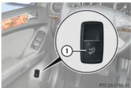
text_image
1 P72.20-2795-31① Remote tailgate opening/closing switch
▶ Pull remote tailgate switch ① until tailgate begins to open. While the tailgate is opening, an acoustic warning sounds.
Closing

Observe Safety notes, see page 68.

Warning!
Maintain sight of the area around the rear of the vehicle while operating the tailgate with the door-mounted remote tailgate switch. Monitor the closing procedure carefully to make sure no one is in danger of being injured.
To interrupt the closing procedure, press or pull the door-mounted remote tailgate switch or press button 📋 on the SmartKey.
In vehicles with power tailgate you can close the tailgate from the inside using the remote tailgate switch.
If the tailgate comes into contact with an object while closing (e.g. luggage that has been piled too high) the closing procedure is stopped and the tailgate reopens.
▶ Switch on the ignition.
▶ Press remote tailgate switch ① until the tailgate begins to close.
The tailgate closes. While the tailgate is closing an acoustic warning sounds.
To interrupt the closing procedure:
▶ Press or pull remote tailgate switch ①.
Limiting opening height of tailgate
You can limit the opening height of the tailgate in the upper opening range. This can be useful, for example, when the space above the tailgate is not sufficient.
Controls in detail
Starter switch positions
Activating
▶ Open tailgate: Pull on handle (▶ page 90) or press and hold button 📋 on the SmartKey until the tailgate opens.
▶ Stop opening procedure: When the tailgate is in the desired position, press tailgate closing switch ( page 93) or press button ☑ on the SmartKey once more.
You can also press or pull the remote tailgate switch (▷ page 94) to stop the opening procedure.
▶ Press and hold the tailgate closing switch in the tailgate (▷ page 93) until you hear a short acoustic signal.
The opening height of the tailgate is limited. The tailgate will now stop at the stored position when opened.
Deactivating
▶ Press and hold the tailgate closing switch in the tailgate until you hear two short, consecutive acoustic signals.
Starter switch positions
SmartKey
⚠️ Observe Safety notes, see page 68.
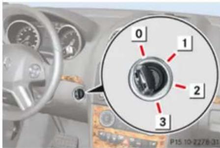
text_image
0 1 2 3 P15 10-2278-31Starter switch
For removing SmartKey
1 Power supply for some electrical consumers, e.g. radio
2 Ignition (power supply for all electrical consumers) and driving position
3 Starting position
When you switch on the ignition, all lamps (except high-beam headlamp indicator lamp, and turn signal indicator lamps unless activated) in the instrument cluster come on. If a lamp in the instrument cluster fails to come on when the ignition is switched on,
have it checked and replaced if necessary. If a lamp in the instrument cluster remains on after starting the engine or comes on while driving, refer to "Lamps in instrument cluster" (▷ page 370).
! If the SmartKey cannot be turned in the starter switch, the vehicle battery may not be sufficiently charged.
- Check the vehicle battery and charge it if necessary.
- Get a jump start.
To prevent accelerated vehicle battery discharge or a completely discharged vehicle battery, always remove the SmartKey from the starter switch when the engine is not in operation.
If the SmartKey does not belong to the vehicle, the SmartKey can be turned in the starter switch. However, the ignition does not switch on and the engine does not start.
Controls in detail
Starter switch positions
KEYLESS-GO

Observe Safety notes, see page 68.
Vehicles equipped with the KEYLESS-GO feature are supplied with a SmartKey with integrated KEYLESS-GO function and a removable KEYLESS-GO start/stop button. With the KEYLESS-GO start/stop button inserted in the starter switch and the SmartKey present in the vehicle, pressing the KEYLESS-GO start/stop button
- without the brake pedal depressed corresponds to the various starter switch positions (▷ page 95)
• with the brake pedal firmly depressed will start the engine ( page 128)
If you wish or should there be the need to insert the SmartKey in the starter switch, the KEYLESS-GO start/stop button can be easily removed by pulling it out of the starter switch.
The KEYLESS-GO start/stop button does not need to be removed from the starter switch when you leave the vehicle. However, always take the SmartKey with you when you leave the vehicle. As long as the SmartKey is in the vehicle, the vehicle's electrical systems can be switched on or
the engine can be started using the KEYLESS-GO start/stop button.
The SmartKey must be located in the vehicle.
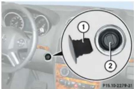
text_image
① ② P15.10-2279-31① KEYLESS-GO start/stop button
② Starter switch
▶ Insert KEYLESS-GO start/stop button ① into starter switch ② (if not inserted already).
▶ Make sure the automatic transmission is in park position P.
▶ Do not depress the brake pedal.
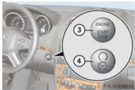
text_image
③ ENGINE START STOP ④ P15 10-2280-31KEYLESS-GO start/stop button
③ USA only
④ Canada only
Position 0
Before you press the KEYLESS-GO start/stop button, the vehicle's on-board electronics have status 0 (as with SmartKey removed).
Position 1
▶ Press the KEYLESS-GO start/stop button once.
This supplies power for some electrical consumers, such as radio functions.
Controls in detail
Seats
i If you now press the KEYLESS-GO start/stop button
- once more, the ignition (position 2) is switched on
- twice more the power supply is again switched off
Ignition (or position 2)
▶ Press the KEYLESS-GO start/stop button twice.
This supplies power for all electrical consumers.
All lamps (except high-beam headlamp indicator lamp and turn signal indicator lamps unless activated) in the instrument cluster come on. If a lamp in the instrument cluster fails to come on when the ignition is switched on, have it checked and replaced if necessary. If a lamp in the instrument cluster remains on after starting the engine or comes on while driving, refer to “Lamps in instrument cluster” (> page 370).
If you now press the KEYLESS-GO start/stop button once, the power supply is again switched off.
Seats
Safety notes
Warning!
In order to avoid possible loss of vehicle control all seat, head restraint, steering wheel, and rear view mirror adjustments, as well as fastening of seat belts, must be done before the vehicle is put into motion.
Warning!
Do not adjust the driver's seat while driving. Adjusting the seat while driving could cause the driver to lose control of the vehicle.
Never ride in a moving vehicle with the seat backrest in an excessively reclined position as this can be dangerous. You could slide under the seat belt in a collision. If you slide under it, the seat belt would apply force at the abdomen or neck. That could cause serious or fatal injuries. The seat backrest and seat belts provide the best restraint when the wearer is in a position that is as upright as possible and seat belts are properly positioned on the body.
Warning!
Your seat must be adjusted so that you can correctly fasten your seat belt.
Observe the following points:
- Adjust the seat backrest until your arms are slightly angled when holding the steering wheel.
- Adjust the seat to a comfortable seating position that still allows you to reach the accelerator/brake pedal safely. The position should be as far back as possible with the driver still able to operate the controls properly.
- Adjust the head restraint so that it is as close to the head as possible and the center of the head restraint supports the back of the head at eye level.
- Never place hands under the seat or near any moving parts while a seat is being adjusted.
Failure to do so could result in an accident and/or serious personal injury.
Warning!
The power seats can be operated at any time. Therefore, do not leave children unattended in the vehicle, or with access to
Controls in detail
Seats
an unlocked vehicle. A child's unsupervised access to a vehicle could result in an accident and/or serious personal injury.

Warning!
According to accident statistics, children are safer when properly restrained in the rear seating positions than in the front seating position. Thus, we strongly recommend that children be placed in the rear seats whenever possible. Regardless of seating position, children 12 years old and under must be seated and properly secured in an appropriately sized infant restraint, toddler restraint, or booster seat recommended for the size and weight of the child. For additional information, see "Children in the vehicle".
A child's risk of serious or fatal injuries is significantly increased if the child restraints are not properly secured in the vehicle and/or the child is not properly secured in the child restraint.

Warning!
For your protection, drive only with properly positioned head restraints.
Adjust the head restraint so that it is as close to the head as possible and the center
of the head restraint supports the back of the head at eye level. This will reduce the potential for injury to the head and neck in the event of an accident or similar situation. Do not drive the vehicle without the seat head restraints. Head restraints are intended to help reduce injuries during an accident.
Seat adjustment
! When moving the seats, make sure there are no items in the footwell or behind the seats. Otherwise, you could damage the seats.
Power seat
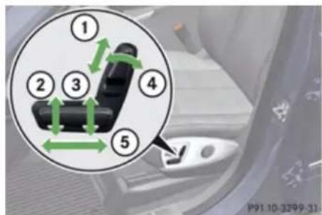
text_image
① ② ③ ④ ⑤ P91.10-3299-31① Head restraint height (vehicles with memory function)
② Seat cushion tilt
③ Seat height
④ Seat backrest tilt
⑤ Seat fore and aft adjustment
! When the second-row seats are folded forward, e.g. for cargo volume expansion, the front seats may not be moved to the rearmost position. Otherwise you could damage the front and second-row seats.
! When adjusting the seat backrest tilt and head restraint height, make sure the sun visor is folded up. If the head restraint is in
Controls in detail
Seats
the uppermost position, it could hit and damage the sun visor.
i Vehicles without memory function: The seats can be adjusted within 5 minutes after either front door has been opened. The counter resets each time
- you open or close a front door
- you insert the SmartKey into the starter switch
- you remove the SmartKey from the starter switch
- you switch the ignition on or off Just like in vehicles with memory function, the power seats can be operated at any time when the ignition is switched on.
The memory function (▷ page 113) lets you store the settings for the seat position together with the settings for the steering wheel (electrical) and exterior rear view mirrors.
▶ Seat fore and aft adjustment: Press the switch forward or backward in direction of arrow ⑤.
▶ Seat backrest tilt: Press the switch forward or backward in direction of arrow ④.
▶ Seat height: Press the switch up or down in direction of arrow ③.
▶ Seat cushion tilt: Press the switch up or down in direction of arrow ② until your upper legs are lightly supported.
▶ Head restraint height: Press the switch up or down in direction of arrow ①.
Head restraint height adjustment, manual
This feature is only available in vehicles without memory function.
Warning!
For your protection, drive only with properly positioned head restraints.
Adjust the head restraint so that it is as close to the head as possible and the center of the head restraint supports the back of the head at eye level. This will reduce the potential for injury to the head and neck in the event of an accident or similar situation.
Do not drive the vehicle without the seat head restraints. Head restraints are intended to help reduce injuries during an accident.
With a rear seat occupied, make sure to move the respective head restraint up from the lowest non-use position and have the occupant adjust the head restraint properly.
! Do not attempt to remove front seat head restraints. They can only be removed by qualified technicians. We recommend that you have this work carried out by an authorized Mercedes-Benz Center.
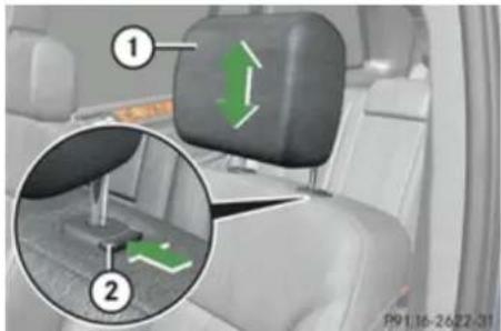
text_image
Diagram showing car seat and seatbelt mechanism with numbered annotations highlighting green directional arrows in the lower-left corner.① Head restraint
② Release button
Controls in detail
Seats
▶ Raising: Adjust the height of head restraint
① manually by pulling it upward.
If head restraint ① is fully retracted, push release button ② in direction of arrow and pull head restraint ① upward.
▶ Lowering: Push release button ② in direction of arrow and press down on head restraint ①.
Head restraint fore and aft adjustment

Warning!
Vehicles with Rear Seat Entertainment System: When adjusting the head restraint, make sure your fingers do not become caught between the head restraint cushion and the monitor. Failing to do so may lead to injury.
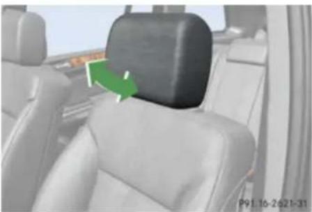
natural_image
Interior view of a car showing the backrest and seat area with green directional arrows indicating movement (no text or symbols)▶ While seated, reach behind you with both hands and find lower edge of the head restraint.
▶ Adjust the head restraint to the desired position by pushing or pulling on the lower edge of the head restraint cushion.
Easy-entry/exit feature for third-row seats
This feature allows for easier access to and exit from the vehicle's third-row seats.

Warning!
To help avoid personal injury, the second-row seat backrests must be properly locked either in the upright position or, when using the expanded cargo volume, in the fully folded position while the vehicle is in motion.
Easy-entry feature for third-row seats
The lever for the easy-entry feature is located on the rear of the seat base of the passenger side second-row seat.
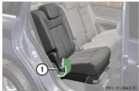
natural_image
Interior view of a car seatbelt with a numbered component (1) highlighted, showing no visible text or symbols.① Easy-entry lever
! Make sure the head restraint is pushed all the way down.
▶ Pull and hold easy-entry lever ① in direction of arrow at resistance point. The seat backrest folds forward.
Controls in detail
Seats
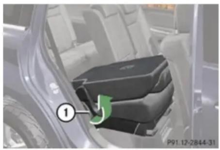
natural_image
Close-up of a car's front compartment showing the seatbelt and door (no text or symbols visible)① Easy-entry lever
▶ Pull and hold easy-entry lever ① once again in direction of arrow at resistance point.
▶ Lift up the right second-row seat until it folds forward.
You should now have sufficient space to access the vehicle's third-row seat.
i Vehicles with memory function:
The front passenger seat moved slightly forward.
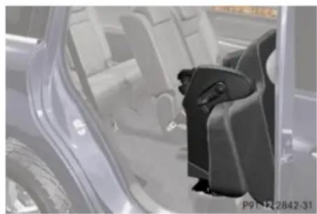
natural_image
Interior view of a car showing a car seatbelt and open door (no visible text or symbols)Easy-entry/exit position
While the easy-entry feature is activated, you will see, for example, the following message in the multifunction display:
2nd Row Of Seats - Right Not Locked
▶ Return seat into its original position.
The message in the multifunction display disappears.
For setting the front passenger seat back into the stored position, see “Recalling positions from memory” (▷ page 114).
▶ Enter the vehicle.
For information on how to fold down the second-row seats completely, see "Expanding cargo volume" (▷ page 235).
For setting the front passenger seat back into the stored position, see “Recalling positions from memory” (▷ page 114).
Easy-exit feature for third-row seats
The easy-exit strap is located on the right rear of the second-row seat base.
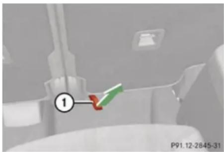
text_image
① P91.12-2845-31Easy-exit strap
▶ To exit the vehicle when seated on a third-row seat, pull up and hold easy-exit strap ①.
The right second-row seat backrest folds forward.
▶ Pull and hold once easy-entry strap ①.
▶ Lift up the right second-row seat until it folds forward.
Controls in detail
Seats
You should now have sufficient space to exit the vehicle's third-row seat.
i Vehicles with memory function:
The front passenger seat moved slightly forward.
While the easy-entry feature is activated, you will see, for example, the following message in the multifunction display:
2nd Row Of Seats - Right Not Locked
▶ Return seat into its original position (▷ page 102).
The message in the multifunction display disappears.
For setting the front passenger seat back into the stored position, see "Recalling positions from memory" (▷ page 114).
For information on how to fold down the second-row seats completely, see "Expanding cargo volume" (> page 235).
Returning second-row seats to their original position
Warning!
When occupants have entered or exited the vehicle using the easy-entry/exit feature, before driving off make sure
• the seats are properly locked
- the seat backrests are in an upright position and are properly locked
If a seat and seat backrest are not properly locked, the seat could move forward and the seat backrest could fold. You could slide under the seat belt during braking, vehicle maneuvers, or in an accident. If you slide under it, the seat belt would apply force at the abdomen or neck. That could cause serious or even fatal injuries.
▶ Fold seat back until it audibly engages.
▶ Fold seat backrest back into original position until it engages.
To make sure the seat backrest has engaged, lean firmly against the seat backrest.
Emergency exit for third-row seats
If, due to an accident or other situation, it is not possible for you to exit the vehicle on the side of the easy-entry seat (▶ page 100), you can fold the left side of the seat backrest in the second row of seats down in order to open the left rear door.
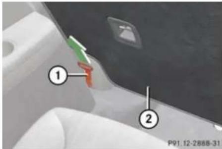
text_image
① ② P91.12-2888-31① Emergency release
② Seat backrest
! Make sure the head restraint is pushed all the way down.
▶ Pull emergency release ① in the direction of arrow.
▶ Push seat backrest ② forwards.
Controls in detail
Seats

Warning!
To help avoid personal injury when folding the seat backrest forward, make sure you move both feet and legs all the way back and out of the way to avoid them contacting the seat as it pivots forward.
In order to prevent an accident or any other potentially dangerous situations when opening the rear door and exiting the vehicle, make sure you are aware of the traffic situation at all times.
▶ Open the left door.
▶ Exit the vehicle.
Lumbar support
You can adjust the contour of the driver's seat lumbar support to help enhance support to your spine.
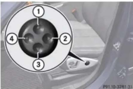
text_image
1 2 3 4 P91.10-3281-31① Curvature up
② Less curvature
③ Curvature down
④ Greater curvature
▶ Curvature position: Use button ① to move the curvature up and button ③ to move it down.
▶ Degree of curvature: Use button ② to lessen the curvature and button ④ to increase it.
Rear seats

Warning!
According to accident statistics, children are safer when properly restrained in the rear seating positions than in the front seating position. Thus, we strongly recommend that children be placed in the rear seats whenever possible. Regardless of seating position, children 12 years old and under must be seated and properly secured in an appropriately sized infant restraint, toddler restraint, or booster seat recommended for the size and weight of the child. For additional information, see "Children in the vehicle".
A child's risk of serious or fatal injuries is significantly increased if the child restraints are not properly secured in the vehicle and/or the child is not properly secured in the child restraint.
Rear seat adjustment

Warning!
Never ride in a moving vehicle with the seat backrest in an excessively reclined position as this can be dangerous. You could slide
▶▶
Controls in detail
Seats
under the seat belt in a collision. If you slide under it, the belt would apply force at the abdomen or neck. That could cause serious or fatal injuries. The seat backrest and seat belts provide the best restraint when the wearer is in a nearly upright position and seat belts are properly positioned on the body.
Your seat must be adjusted so that you can correctly fasten your seat belt.
Never place hands under the seat or near any moving parts while a seat is being adjusted.
After adjusting rear seats, make sure
• the seats are properly locked
• the seat backrests are in an upright position and are properly locked
Check for secure locking by pushing and pulling on the seat backrests. If a seat and seat backrest are not properly locked, the seat could move forward and the seat backrest could fold. The child seat would no longer be properly supported or positioned to provide its intended benefit.
Seat backrest tilt (second-row seats)
Warning!
The seat belt only offers its intended protection when the seat backrest is in a nearly vertical position and the occupant is sitting upright. Avoid sitting in positions that prevent the seat belt from being properly positioned against the body. You should therefore adjust the seat backrest to a position as upright as possible.
The seat backrest tilt can be set to five different positions.
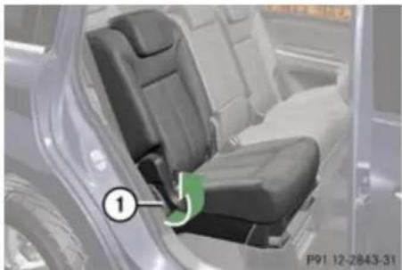
natural_image
Interior view of a car showing the seat and driver seat, with a numbered label pointing to the side panel (no readable text or symbols)① Adjustment handle
▶ While seated, pull handle ① in direction of arrow to resistance point and hold it there.
▶ To move seat backrest back, lean lightly against the seat backrest.
▶ To move seat backrest forward, lean forward with handle ① pulled and held at resistance point.
The seat backrest will move forward against your back.
▶ Release handle ① when the seat backrest has reached the desired position.
To make sure the seat backrest has engaged, lean firmly against the seat backrest.
Head restraint height
Warning!
With a rear seat occupied, make sure to move the respective head restraint up from the lowest non-use position and have the occupant adjust the head restraint properly.
For your protection, drive only with properly positioned head restraints.
Adjust the head restraint so that it is as close to the head as possible and the center
Controls in detail
Seats
of the head restraint supports the back of the head at eye level. This will reduce the potential for injury to the head and neck in the event of an accident or similar situation.
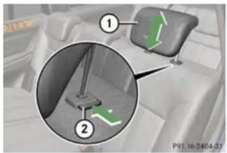
text_image
Diagram showing car interior with labeled parts and directional arrows, including a green arrow indicating movement.Second-row seat head restraint
① Head restraint
② Release button
▶ Raising: Manually adjust the height of head restraint ① by pulling it upward to the desired position.
▶ Lowering: Push release button ② and press down on head restraint ①.
The third-row seat head restraints are adjusted in the same manner.
Head restraint fore and aft adjustment
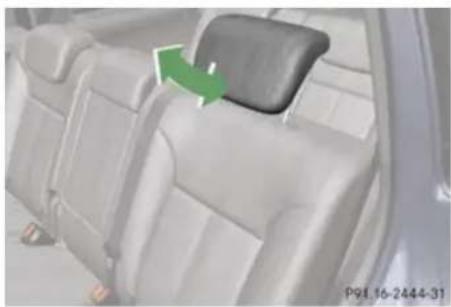
natural_image
Interior view of a car backseat showing the seat and neck area with a green arrow indicating direction (no text or symbols)The angle of the head restraint for the outer second-row seats or the third-row seats can be adjusted manually.
▶ While seated, reach behind you with both hands and find lower edge of the head restraint.
▶ Adjust the head restraint to the desired position by pushing or pulling on the lower edge of the head restraint cushion.
Head restraints, removing and installing
Warning!
Do not drive the vehicle without the seat head restraints installed when the rear
seats are occupied. Head restraints are intended to help reduce injuries during an accident.
With a rear seat occupied, make sure to move the respective head restraint up from the lowest non-use position and have the occupant adjust the head restraint properly.
For your protection, drive only with properly positioned head restraints.
Adjust the head restraint in such a way that it is as close to the head as possible and the center of the head restraint supports the back of the head at eye level. This will reduce the potential for injury to the head and neck in the event of an accident or similar situation.
Controls in detail
Seats
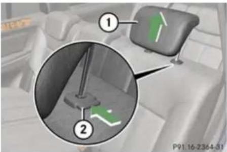
text_image
Diagram showing car seat positioning with numbered annotations and directional arrows indicating movement or movement.Second-row seat head restraint
① Head restraint
② Release button
Removing
▶ Second-row seat: Fold the seat backrest forward (▷ page 104).
▶ Third-row seat: Fold the seat backrest forward (▷ page 235).
▶ Pull head restraint ① to its uppermost position.
▶ Press release button ② and pull out head restraint ①.
▶ Second-row seat: Fold the seat backrest rearward until it engages.
▶ Third-row seat: Fold the seat backrest rearward (▷ page 235).
Installing
▶ Second-row seat: Fold the seat backrest forward (▷ page 104).
▶ Third-row seat: Fold the seat backrest forward (▷ page 235).
▶ Insert head restraint ① into openings on the seat backrest.
▶ Push head restraint ① down until it audibly engages.
▶ Push release button ② and adjust head restraint ① to the desired position (▶ page 104).
Second-row seat: Fold the seat backrest rearward until it engages.
Third-row seat: Fold the seat backrest rearward ( page 235).
Multicontour seat
The multicontour seat has a movable seat cushion and inflatable air cushions built into the seat backrest to provide additional lumbar and side support.
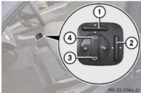
text_image
① ② ③ ④ P91 25-2366-31① Seat cushion depth
② Seat backrest side bolster
③ Seat backrest center
④ Seat backrest bottom
▶ Switch on the ignition.
▶ Seat cushion depth: Adjust the seat cushion depth to the length of your upper leg using switch ①.
▶ Seat backrest contour: Adjust the contour of the seat backrest to the desired position using + or - .
Controls in detail
Seats
▶ Move the seat backrest support cushion to the bottom with button ④ or to the center with button ③.
▶ Seat backrest side bolsters: Adjust the side bolsters so that they provide good lateral support using switch ②.
Seat ventilation
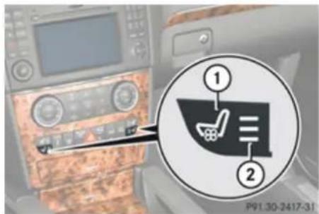
text_image
① ② P91.30-2417-31① Seat ventilation switch
② Indicator lamps
The blue indicator lamps in the switch come on to show which ventilation level you have selected.
i The seat ventilation for the driver's seat can be activated using summer opening feature (> page 127).
▶ Switch on the ignition.
▶ Switching on: Press switch ①.
Three blue indicator lamps ② in the switch come on.
▶ Press switch ① repeatedly until the desired ventilation level is set.
▶ Switching off: Press switch ① repeatedly until all indicator lamps ② go out.
Seat heating
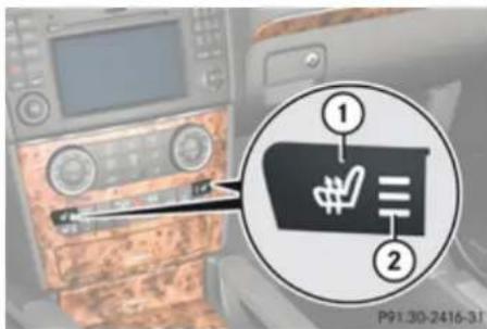
text_image
Automotive infotainment diagram showing car dashboard with labeled parts and a magnified view of the device's internal components.① Front seat heating switch
② Indicator lamps
The switches for the outboard second-row seat heating are located in the rear center console.
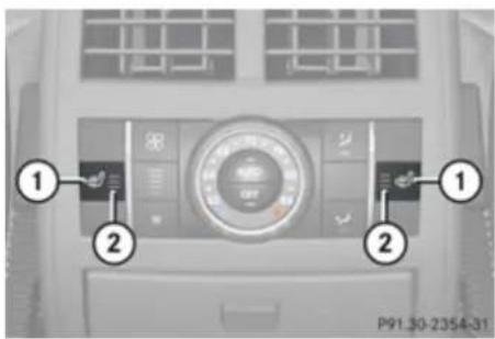
text_image
Control panel diagram of a car air conditioner with labeled buttons and dials① Rear seat heating switch
② Indicator lamps
The red indicator lamps in the switch come on to show which heating level you have selected.
The seat heating switches from level 3 (high) to level 2 after approximately 5 minutes.
The seat heating switches from level 2 to level 1 (low) after approximately 10 minutes.
The seat heating automatically switches off after approximately 20 minutes.
▶ Switch on the ignition.
▶ Switching on: Press switch ①.
Three red indicator lamps ② in the switch come on.
▶▶
Controls in detail
Multifunction steering wheel
▶ Continue pressing switch ① until desired seat heating level is reached.
▶ Switching off: Press switch ① repeatedly until all indicator lamps ② go out.
If one or more of the indicator lamps ② in the seat heating switch ① are flashing, there is insufficient voltage available since too many electrical consumers are turned on. The seat heating switches off automatically.
The seat heating will switch back on again automatically as soon as sufficient voltage is available.
Multifunction steering wheel
Safety notes
Warning!
Do not adjust the steering wheel while driving. Adjusting the steering wheel while driving, or driving without the steering wheel adjustment feature locked could cause the driver to lose control of the vehicle.
The electrical steering wheel adjustment feature can be operated at any time. Therefore, do not leave children unattended in the vehicle, or with access to an unlocked vehicle. A child's unsupervised access to a vehicle could result in an accident and/or serious personal injury.
Make sure
- you can reach the steering wheel with your arms slightly bent at the elbows
• you can move your legs freely - all displays (including malfunction and indicator lamps) on the instrument cluster are clearly visible
Steering wheel adjustment, manual (USA only)
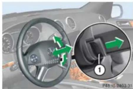
natural_image
Interior view of a car showing steering wheel and dashboard with directional arrows indicating motion (no text or symbols)① Release handle
▶ Unlocking: Pull release handle ① out to its stop limit.
▶ Move steering wheel to the desired position.
▶ Locking: Push release handle ① back to its original position.
▶ Make sure the steering wheel is securely locked by trying to move it up and down as well as in and out before driving off.
Steering wheel adjustment, electrical
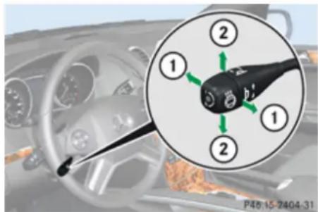
text_image
1 2 1 2 P45:15-2404-31① Adjusting steering wheel, in or out
② Adjusting steering wheel, up or down
▶ Adjusting steering wheel in or out: Move stalk in direction of arrows ①.
▶ Adjusting steering wheel up or down:
Move stalk in direction of arrows ②.
The memory function ( page 113) lets you store the settings for the steering wheel together with the settings for the seat position and the exterior rear view mirrors.
Easy-entry/exit feature
This feature allows the driver an easier entry into and exit from the vehicle. When entering and exiting the vehicle, the steering wheel is in its uppermost position.
The easy-entry/exit feature can be activated or deactivated in the Comfort submenu of the control system (▷ page 163).
Warning!
You must make sure no one can become trapped or injured by the moving steering wheel when the easy-entry/exit feature is activated.
To stop steering wheel movement do one of the following:
- Move steering wheel adjustment stalk.
- Press one of the memory position buttons.
- Press memory button M.
Do not leave children unattended in the vehicle, or with access to an unlocked vehicle. Children could open the driver's door and unintentionally activate the easy-entry/exit feature, which could result in an accident and/or serious personal injury.
Multifunction steering wheel
With the easy-entry/exit feature activated, the steering wheel will return to its last set position when you close the driver's door with the ignition switched on. The steering wheel will also return to its last set position when you insert the SmartKey into the starter switch or press the KEYLESS-GO start/stop button once with the driver's door closed.
i The last set steering wheel position is stored when the ignition is switched off or the position is stored in memory ( page 114).
With the easy-entry/exit feature activated, the steering wheel tilts upwards when you remove the SmartKey from the starter switch. The steering wheel also tilts upwards when you open the driver's door with the SmartKey in starter switch position 0 or 1 or the KEYLESS-GO start/stop button in position 1.
When the current position for the steering wheel is in the uppermost tilt position, the steering wheel will no longer be able to move upward when the easy-entry/exit feature is activated.
The adjustment procedure is briefly interrupted when the engine is started.
Controls in detail
Multifunction steering wheel

Warning!
Let the system complete the adjustment procedure before setting the vehicle in motion. All steering wheel adjustment must be completed before setting the vehicle in motion. Driving off with the steering wheel still adjusting could cause the driver to lose control of the vehicle.
Heated steering wheel
The steering wheel heating warms up the leather area of the steering wheel.
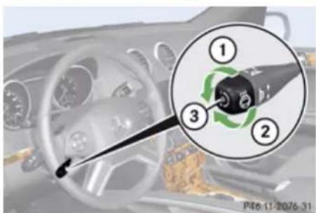
text_image
Diagram showing car steering wheel and keyway with numbered parts, including a close-up inset of the keyway's winding.① Switching on
② Switching off
③ Indicator lamp
▶ Switch on the ignition.
▶ Switching on: Turn switch at the tip of the stalk in direction of arrow ①.
Indicator lamp ③ comes on.
The steering wheel heating may be suspended temporarily. However, indicator lamp ③ remains on. The steering wheel heating is suspended when the temperature of the vehicle interior is above 86°F (30°C). It is also suspended when the temperature of the steering wheel is above 95°F (35°C).
When these conditions do not apply anymore, steering wheel heating continues.
▶ Switching off: Turn switch at the tip of stalk in direction of arrow ②. Indicator lamp ③ goes out.
i Indicator lamp ③ flashes or goes out in case of power surge or undervoltage or if the steering wheel heating malfunctions.
The steering wheel heating switches off automatically when you remove the SmartKey from the starter switch or, on vehicles with KEYLESS-GO, when you
switch off the ignition and open the driver's door.
For more information on the steering wheel, see "Multifunction steering wheel" (▷ page 148).
Controls in detail
Mirrors
Mirrors
Notes
Adjust the interior and exterior rear view mirrors before driving so that you have a good view of the road and traffic conditions.
Interior rear view mirror
▶ Adjust the interior rear view mirror manually.
For more information, see "Auto-dimming rear view mirrors" (▷ page 112).
Interior rear view mirror, antiglare position
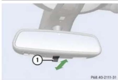
natural_image
Close-up of a white car rearview mirror with a green arrow pointing to the side panel (no text or symbols visible)① Lever
▶ Tilt the mirror to the antiglare position by moving lever ① towards the windshield. The interior rear view mirror is dimmed.
Exterior rear view mirrors
Warning!
Exercise care when using the passenger-side exterior rear view mirror. The mirror surface is convex (outwardly curved surface for a wider field of view). Objects in mirror are closer than they appear. Check your interior rear view mirror and glance over your shoulder before changing lanes.
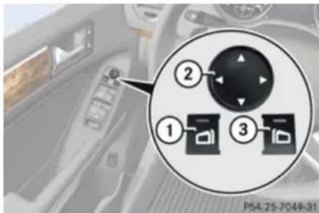
text_image
① ② ③ P54-25-7049-31① Driver's side exterior rear view mirror button
② Adjustment button
③ Passenger-side exterior rear view mirror button
▶ Switch on the ignition.
Press button ① for the driver's side exterior rear view mirror or button ③ for the passenger-side exterior rear view mirror.
The indicator lamp in the respective button comes on for approximately 15 seconds. If you do not make adjustments to the selected exterior rear view mirror within 15 seconds, the indicator lamp goes out. You will then have to select the desired exterior rear view mirror again before adjustments can be made. Adjustments can only be made with the indicator lamp for the respective exterior rear view mirror button illuminated.
▶ Press adjustment button ② up, down, left or right according to the desired setting.
! If an exterior rear view mirror was forcibly hit from the front, manually snap it back into place.
! Vehicle with power folding exterior rear view mirrors:
▶▶
Controls in detail
Mirrors
If an exterior rear view mirror housing is forcibly pushed forward (hit from the rear) or forcibly pushed rearward (hit from front), press fold button to fold mirrors in, then press fold button again to fold mirrors out. Do not force mirrors by hand as this may damage the adjustment mechanism.
The mirror housing is then properly positioned and you can adjust the mirror in the usual manner.
At low ambient temperatures, the exterior rear view mirrors will be heated automatically.
Auto-dimming rear view mirrors
The exterior rear view mirror on the driver's side and the interior rear view mirror will respond automatically to glare when the ignition is switched on and incoming light from headlamps falls on the sensor in the interior rear view mirror.
The rear view mirrors will not react if the automatic transmission is set to reverse gear R or the interior lighting is switched on.
Warning!
The auto-dimming function does not react if incoming light is not aimed directly at sensors in the interior rear view mirror. The interior rear view mirror and the exterior rear view mirror on the driver's side do not react, for example, when transporting cargo which covers the rear window.
Light hitting the mirror(s) at certain angles (incident light) could blind you. As a result, you may not be able to observe traffic conditions and could cause an accident.
Power folding exterior rear view mirrors
! Before you drive the vehicle through an automatic car wash, fold in the exterior rear view mirrors. Otherwise they may get damaged.
Folding in and out automatically
When the corresponding function in the control system is activated (▷ page 164):
- The exterior rear view mirrors fold in automatically as soon as the vehicle is locked from the outside.
- The exterior rear view mirrors fold out automatically as soon as the vehicle is unlocked and the driver's or front passenger door are subsequently opened.
Synchronizing
The power folding rear view mirrors may have to be synchronized after the vehicle battery has been disconnected or discharged. If the exterior rear view mirrors do not fold properly upon locking or unlocking the vehicle although the corresponding function in the control system is activated (▷ page 164), do the following:
▶ Fold each exterior rear view mirror in completely (▷ page 113).
▶ Fold each exterior rear view mirror out completely (▷ page 113).
When the exterior rear view mirrors fold properly upon locking the vehicle, the exterior mirrors are synchronized. Otherwise repeat the above steps.
Folding in and out manually
The exterior rear view mirrors can vibrate if they are not folded out completely.
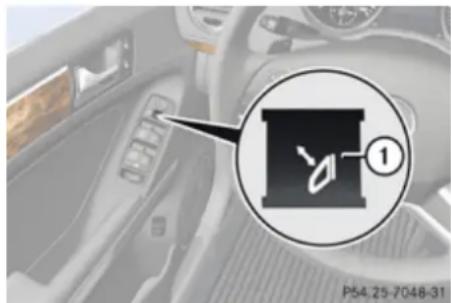
text_image
P54.25-7048-31① Button for folding exterior rear view mirrors in and out
▶ Switch on the ignition.
▶ Folding in: Briefly press button ①. Both exterior rear view mirrors fold in.
If you are driving at more than approximately 30 mph (47 km/h), you will not be able to fold the exterior mirrors in.
▶ Folding out: Briefly press button ①. Both exterior rear view mirrors fold out.
! If an exterior rear view mirror housing is forcibly pushed forward (hit from the rear) or forcibly pushed rearward (hit from the front), press button ① to fold mirrors in, then press button ① again to fold mirrors out. Do not force mirrors by hand as this may damage the adjustment mechanism.
The mirror housing is then properly positioned and you can adjust the mirror in the usual manner.
Please make sure both rear view mirrors are folded out before driving off.
Memory function
Notes
With the memory function you can store up to three different configurations per front seat.
Each memory position button on the driver's side can store all of the following settings:
- Seat position
- Multicontour seat: previously saved setting
• Steering wheel position - Exterior rear view mirrors' position
Warning!
Do not activate the memory function while driving. Activating the memory function while driving could cause the driver to lose control of the vehicle.
Each memory position button on the front passenger side can store all of the following settings:
- Seat position
• Multicontour seat: previously saved setting
Controls in detail
Lighting
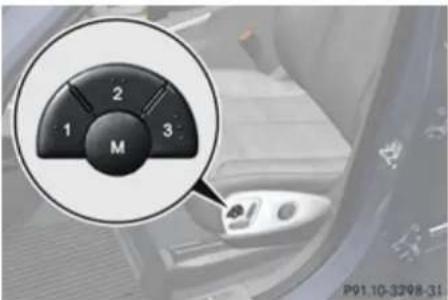
text_image
1 2 3 M P91.10-3298-31M Memory button
1, 2, 3 Memory position button
Storing positions into memory
Adjust the seats.
On the driver's side, additionally adjust the steering wheel and exterior rear view mirrors to the desired positions.
▶ Press memory button M.
▶ Release memory button M and press memory position button 1, 2 or 3 within 3 seconds.
When the settings are stored to the selected position, an acknowledgement signal sounds.
Recalling positions from memory
▶ Press and hold desired memory position button 1, 2 or 3 until the seat has completely moved to the stored position. On the driver's side, also wait for the steering wheel and exterior rear view mirrors to move to the stored position.
i Releasing the memory position button stops movement to the stored positions immediately.
Lighting
Notes
If you drive in countries where vehicles drive on the other side of the road than the country where the vehicle is registered, you must have the headlamps modified for symmetrical low beams. Relevant information can be obtained at any authorized Mercedes-Benz Center.
i Vehicles equipped with active Bi-Xenon headlamps:
The active Bi-Xenon headlamps monitor the vehicle's steering angle and speed, then automatically shift their beams to either side to better follow the curvature of the road ahead, increasing usable illumination over conventional headlamps.
Controls in detail
Lighting
Exterior lamp switch
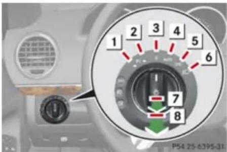
text_image
1 2 3 4 5 6 7 8 P54 25-6395-311 -P Standing lamps, left
2 P≤ Standing lamps, right
3 0 Off
Daytime running lamp mode
4 AUTO Automatic headlamp mode Daytime running lamp mode
5 Parking lamps (also tail lamps, license plate lamps, side marker lamps and instrument panel lamps)
6 Low-beam headlamps or high-beam headlamps
7 #D Front fog lamps
8 0# Rear fog lamp
The exterior lamps go out automatically when you remove the SmartKey from the
starter switch or open the driver's door with the ignition switched off.
When the parking lamps or the rear fog lamp are switched on and you remove the SmartKey from the starter switch or open the driver's door, an acoustic signal sounds.
In addition the message Switch Off Lights appears in the multifunction display.
Switch off the parking lamps or the rear fog lamp manually.
! Failure to switch off the parking lamps when leaving the vehicle may result in a discharged battery.
Low-beam headlamps
The low-beam headlamps can be switched on and off with the exterior lamp switch.
▶ Switch on the ignition.
Switching on: Turn the exterior lamp switch to position 📋.
The following lamps come on:
- Low-beam headlamps
- Tail lamps
-
Parking lamps
-
License plate lamps
- Side marker lamps
- Instrument panel lamps
- Green indicator lamp ≧00 in the exterior lamp switch
▶ Switching off: Turn the exterior lamp switch to position 0.
Automatic headlamp mode
The following lamps come on and go out automatically depending on the brightness of the ambient light:
- Low-beam headlamps
- Tail lamps
- Parking lamps
- License plate lamps
- Side marker lamps
Warning!
If the exterior lamp switch is set to AUTO, the headlamps will not automatically come on under foggy conditions.
To minimize risk to you and to others, activate headlamps by turning exterior lamp switch to 📋 when driving or when
▶▶
Controls in detail
Lighting
traffic and/or ambient lighting conditions require you to do so.
In low ambient lighting conditions, only switch from position AUTO to 📋 with the vehicle at a standstill in a safe location.
Switching from AUTO to 📋 will briefly switch off the headlamps. Doing so while driving in low ambient lighting conditions may result in an accident.
The automatic headlamp feature is only an aid to the driver. The driver is responsible for the operation of the vehicle's lights at all times.
▶ Switching on: Turn the exterior lamp switch to position AUTO.
With the SmartKey in starter switch position 1 or the KEYLESS-GO start/stop button pressed once, the tail and parking lamps, the license plate lamps and the side marker lamps will come on and go out depending on the brightness of the ambient light.
When the engine is running the low-beam headlamps, the tail and parking lamps, the license plate lamps and the side marker lamps will come on and go out depending on the brightness of the ambient light.
Canada only: High-beam headlamps are only available with the exterior lamp switch in position 🔒.
Daytime running lamp mode
In Canada, the daytime running lamp mode is mandatory and therefore in a constant mode. In the USA, the daytime running lamp mode is deactivated by default. Activate the daytime running lamp mode using the control system, see "Setting daytime running lamp mode (USA only)" (> page 161).
▶ Turn the exterior lamp switch to position
0 or AUTO.
When the engine is running, the low-beam headlamps come on.
In low ambient lighting conditions, the following lamps will come on additionally:
- Tail lamps
- Parking lamps
- License plate lamps
- Side marker lamps
With the daytime running lamp mode activated and the engine running, you cannot switch off the low-beam headlamps manually.
Canada only
With the exterior lamp switch in position
0 or AUTO, you cannot switch on the high-beam headlamps.
The high-beam flasher is available at all times.
For nighttime driving turn the exterior lamp switch to position 📋 to permit activation of the high-beam headlamps.
When the engine is running, and you
- shift from a driving position to neutral position N or park position P with the vehicle at a standstill, the low-beam headlamps will go out with a delay of 3 minutes
- turn the exterior lamp switch to position ≥000 , the low-beam headlamps, the tail and parking lamps, the license plate lamps and the side marker lamps come on
- turn the exterior lamp switch to position 📋, the manual headlamp mode has priority over the daytime running lamp mode
The corresponding exterior lamps come on (▷ page 115).
USA only
With the exterior lamp switch in position 0, you cannot switch on the high-beam headlamps.
The high-beam flasher is available at all times. For nighttime driving turn the exterior lamp switch to position 📋 or AUTO to permit activation of the high-beam headlamps.
When the engine is running, and you turn the exterior lamp switch to position 300 or ID, the manual headlamp mode has priority over the daytime running lamp mode. The corresponding exterior lamps come on (▷ page 115).
Fog lamps
Fog lamps cannot be switched on with the exterior lamp switch in position AUTO. To switch on the fog lamps, turn the exterior lamp switch to position 📋 first.

Warning!
In low ambient lighting or foggy conditions, only switch from position AUTO to 📋 with the vehicle at a standstill in a safe location.
Switching from AUTO to 📋 will briefly switch off the headlamps. Doing so while driving in low ambient lighting conditions may result in an accident.
Fog lamps will operate with the parking lamps and/or the low-beam headlamps on. Fog lamps should only be used in conjunction with low-beam headlamps. Consult your State or Province Motor Vehicle Regulations regarding permissible lamp operation.
▶ Switch on the ignition.
▶ Turn the exterior lamp switch to position →DOE or 📋 (▷ page 115).
Switching on front fog lamps: Pull out the exterior lamp switch to first stop. The green indicator lamp #0 in the exterior lamp switch comes on.
Switching on rear fog lamp: Pull out the exterior lamp switch to second stop. The rear fog lamp, the front fog lamps and the yellow indicator lamp 0 in the exterior lamp switch come on.
▶ Switching off front fog lamps/rear fog lamp: Push in the exterior lamp switch to its stop.
Locator lighting and night security illumination
Locator lighting and night security illumination are described in the “Control system” section, see “Setting locator lighting” ( page 161) and “Setting night security illumination (Headlamps delayed shut-off feature)” ( page 162).
Combination switch
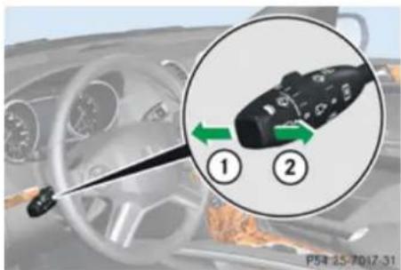
text_image
Diagram showing car steering wheel and hand valve with directional arrows and numbered parts, likely illustrating a steering or steering system.① High beam
② High-beam flasher
Controls in detail
Lighting
High beam
▶ Turn the exterior lamp switch to position (▷ page 115).
Switching on: Push the combination switch in direction of arrow ①.
The high-beam headlamp indicator lamp in the instrument cluster comes on.
▶ Switching off: Pull the combination switch in direction of arrow ② to its original position.
High-beam flasher
▶ Switching on: Pull the combination switch briefly in direction of arrow ②.
Turn signals

text_image
① ② P54-25-7018-31① Turn signals, right
② Turn signals, left
▶ Press the combination switch in direction of arrow ① or ②.
The corresponding turn signal indicator lamp or in the instrument cluster flashes.
The combination switch resets automatically after major steering wheel movements.
To signal minor directional changes such as changing lanes, press combination switch only to point of resistance and release. The corresponding turn signal lamps will flash three times.
Hazard warning flasher
The hazard warning flasher can be switched on at all times, even with the SmartKey removed from the starter switch.
The hazard warning flasher comes on automatically when an air bag deploys.
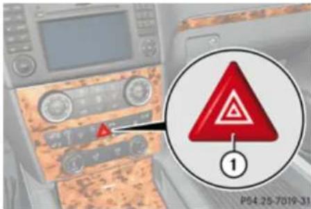
text_image
P64 25-7019-31 ①① Hazard warning flasher switch
▶ Switching on: Press hazard warning flasher switch ①.
All turn signal lamps are flashing.
With the hazard warning flasher activated and the combination switch set for either left or right turn, only the respective left or
Controls in detail
Lighting
right turn signals will operate when the ignition is switched on.
▶ Switching off: Press hazard warning flasher switch ① again.
If the hazard warning flasher has been activated automatically, press hazard warning flasher switch ① once to switch off.
Headlamp cleaning system
The headlamps will be cleaned with a high-pressure water jet automatically when the engine is running and you have
- switched on the headlamps and
- the windshield wipers have wiped the windshield with washer fluid five times
The counter resets when you switch off the headlamps.
For information on filling up the washer reservoir, see “Washer system and headlamp cleaning system” ( page 271).
Corner-illuminating front fog lamps
The corner-illuminating front fog lamps improve illumination of the area in the direction into which you are turning.
The corner-illuminating front fog lamps will only operate
• in low ambient lighting conditions
• at vehicle speeds below 25 mph (40 km/h)
• with the front fog lamps switched off
• with the engine is running
Switching on
▶ Turn the exterior lamp switch to position 📋 or AUTO.
or
▶ Activate the daytime running lamp mode (▷ page 116).
▶ Switch on the left or right turn signal, depending on whether you are turning left or right.
The respective front fog lamp comes on. If you have switched on the turn signal for one side but turn the steering wheel in the other direction, the corner-illuminating
front fog lamp comes on on the side of the turn signal.
or
▶ Turn steering wheel in the desired direction.
Driving forward: The front fog lamp on the side of your steering direction comes on.
Driving in reverse: The front fog lamp opposite to your steering direction comes on.
The corner-illuminating front fog lamps will come on automatically depending on the steering angle, even if you did not switch on either turn signal. If the corner-illuminating front fog lamps came on automatically, they will also go out automatically depending on the steering angle and vehicle speed.
The corner-illuminating front fog lamps temporarily come on on both sides of the vehicle if you turn the steering wheel in one direction and then again in the other direction shortly thereafter.
The corner-illuminating front fog lamp remains lit for a maximum of 3 minutes. Afterward, it goes out even if the turn signal is still switched on.
Controls in detail
Lighting
Switching off
▶ Switch off the left or right turn signal.
or
▶ Steer straight ahead.
There may be a brief delay before the corner-illuminating front fog lamps go out.
Interior lighting in the front
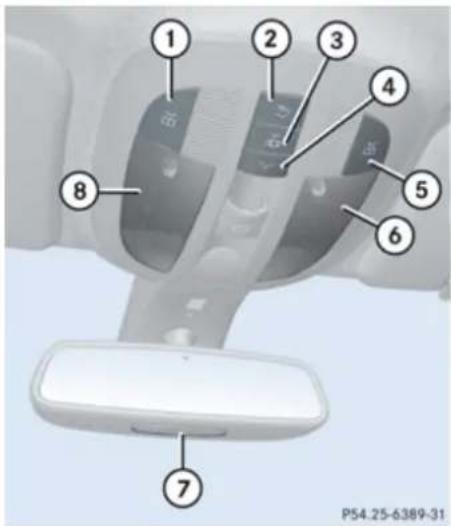
text_image
1 2 3 4 5 6 7 8 P54.25-6389-31① Left front reading lamp on/off
② Rear interior lighting on/off
③ Automatic control on/off
④ Front interior lighting on/off
⑤ Right front reading lamp on/off
⑥ Front interior lighting
⑦ Front reading lamps
⑧ Front interior lighting
Automatic control
▶ Activating: Press button
Button disengages and sits flush with the other buttons.
The interior lighting and the locator lighting (▷ page 161) come on in darkness, when you:
- unlock the vehicle
- remove the SmartKey from the starter switch
- open a door
- open the tailgate
▶ Deactivating: Press button
Button engages.
The interior lighting goes out after a preset time (▷ page 162).
If a door remains open, the interior lamps go out automatically after approximately 5 minutes when the SmartKey is removed or in starter switch position 0.
Manual control
! An interior lamp switched on manually does not go out automatically.
Controls in detail
Lighting
Leaving an interior lamp switch in the ON position for extended periods of time with the engine turned off could result in a discharged battery.
Switching on/off front interior lighting: Press switch
▶ Switching on/off rear interior lighting:
Press switch 📋.
▶ Switching on/off front reading lamps: Press respective switch 📁.
Emergency lighting
When the interior lighting is set to automatic mode, the interior lighting is activated automatically if the vehicle is involved in an accident.
Switching off: Press button
or
▶ Press hazard warning flasher switch (▶ page 118).
or
▶ Unlock the vehicle.
Interior lighting in the rear
! An interior lamp switched on manually does not go out automatically. Leaving an interior lamp switch in the ON position for extended periods of time with the engine turned off could result in a discharged battery.
Second-row reading lamps
The second-row reading lamps are located above the rear door windows.

text_image
P54.25-6388-31① Second-row reading lamp
▶ Switching on/off rear reading lamps: Press second-row reading lamp ① as indicated by the arrow.
Third-row reading lamps
The third-row reading lamps are located in the rear overhead control panel.
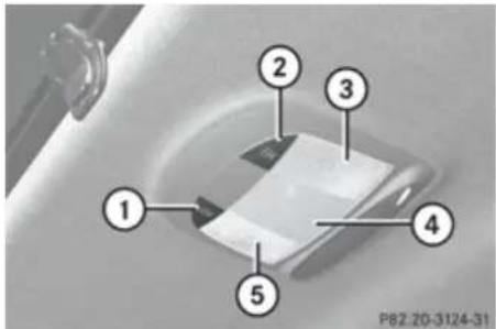
text_image
1 2 3 4 5 P82-20-3124-31① 盖 Right third-row reading lamp on/off
② Left third-row reading lamp on/off
③ Left third-row reading lamp
④ Rear interior lighting
⑤ Right third-row reading lamp
Switching on/off third-row reading lamps: Press respective reading lamp switch
The rear interior lighting is switched on and off using the button on the front overhead control panel (▷ page 120).
Controls in detail
Wipers
Wipers
Notes
! Do not operate the wipers when the windshield/rear window is dry. Dust that accumulates on a windshield/rear window might scratch the glass and/or damage the wiper blades when wiping occurs on a dry windshield/rear window. If it is necessary to operate the wipers in dry weather conditions, always operate the wipers with washer fluid.
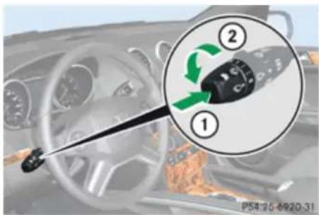
text_image
① ② P54 26-6920-31Combination switch
① Single wipe
Wiping with washer fluid
② Switching on windshield wipers
▶ Switch on the ignition.
Windshield wipers
Switching on/off
| 0 | Windshield wipers off |
| ... | Slow intermittent wipingRain sensor operation with low sensitivity. |
| ... | Fast intermittent wipingRain sensor operation with high sensitivity. |
| — | Slow continuous wiping |
| = | Fast continuous wiping |
▶ Turn the combination switch in direction of arrow ② to the desired position, depending on the intensity of the rain.
Intermittent wiping
Only switch on intermittent wiping under wet weather conditions or in the presence of precipitation.
When you select intermittent wiping, the rain sensor is activated. The rain sensor sets a
suitable wiping interval depending on the wetness of the sensor surface automatically.
! Do not leave windshield wipers on an intermittent setting when the vehicle is taken to an automatic car wash or during windshield cleaning. Windshield wipers will operate in the presence of water sprayed on the windshield, and windshield wipers may be damaged as a result.
! If you have set intermittent wiping, dirt on the surface of the rain sensor or optical effects may cause the windshield wipers to wipe in an undesired fashion. This could then damage the windshield wiper blades or scratch the windshield. You should therefore switch off the windshield wipers when weather conditions are dry.
▶ Turn the combination switch to position
.... or ....
After the initial wipe, pauses between wipes are controlled by the rain sensor automatically.
Intermittent wiping is interrupted when the vehicle is at a standstill and a front door is opened. This protects persons getting into or out of the vehicle from being sprayed.
Controls in detail
Wipers
Intermittent wiping will be continued when all doors are closed and
• the automatic transmission is in drive position D or reverse gear R or
- the wiper setting is changed using the combination switch
Single wipe
▶ Press the combination switch briefly in direction of arrow ① to the resistance point.
The windshield wipers wipe one time without washer fluid.
Wiping with washer fluid
▶ Press the combination switch in direction of arrow ① past the resistance point. The windshield wipers operate with washer fluid.
To prevent smears on the windshield or noisy/chattering wiper blades, wipe with washer fluid every now and then even when it is raining.
For information on filling up the washer reservoir, see "Washer system and headlamp cleaning system" (▷ page 271).
For information on cleaning the headlamps with washer fluid, see "Headlamp cleaning system" (▷ page 119).
Rear window wiper/washer
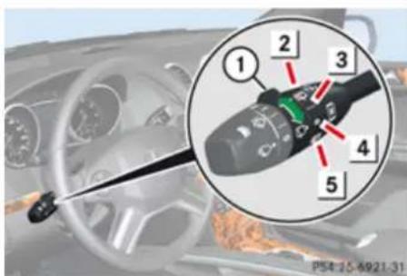
text_image
1 2 3 4 5 P54-15-6921-31Combination switch
① Rear window wiper switch
2 Wiping rear window with washer fluid
3 Intermittent wiping
4 Rear window wiper off
5 Wiping rear window with washer fluid
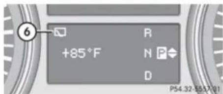
text_image
+85°F R N P D P54.32-557-91⑥ Rear window wiper indicator
▶ Switch on the ignition.
The rear window wiper engages automatically when the automatic transmission is shifted into reverse gear R with the windshield wipers switched on.
▶ Activating intermittent wiping: Turn rear window wiper switch ① to position ③. In the lower multifunction display you will see rear window wiper indicator ⑥, indicating that the rear window wiper is activated.
▶ Deactivating intermittent wiping: Turn rear window wiper switch ① to position ④.
Indicator ⑥ for the rear window wiper is cleared from the lower multifunction
Controls in detail
Power windows
display, indicating that the rear window wiper is deactivated.
▶ Wiping with washer fluid: Turn and hold rear window wiper switch ① in position ② or ⑤ until the rear window is clean.
For information on filling up the washer reservoir, see “Washer system and headlamp cleaning system” (▷ page 271).
Problems with wipers
! If anything blocks the windshield wipers (leaves, snow, etc.), switch them off immediately.
For safety reasons, stop the vehicle in a safe location, and
- remove the SmartKey from the starter switch
or - turn off the engine by pressing the KEYLESS-GO start/stop button and open the driver's door (with the driver's door open, starter switch is in position 0, same as with SmartKey removed from starter switch)
- engage the parking brake
before attempting to remove any blockage.
- Remove blockage.
- Turn the windshield wipers on again.
If the windshield wipers fail to function at all with the combination switch in position
- set the combination switch to the next higher wiper speed
• have the windshield wipers checked at the nearest authorized Mercedes-Benz Center
Power windows
Opening and closing
The door windows and the hinged quarter windows are opened and closed electrically. The switches for all door windows and the hinged quarter windows are located on the driver's door control panel. The switches for the respective door windows are located on the front passenger door and the rear doors. The hinged quarter windows can be operated from the driver's seat only.
i Operating the rear door windows from the rear is not possible when you activate the override switch (▷ page 74).
Vehicles equipped with the PRE-SAFE® system: If the vehicle is in a severe skid or is spinning, the door windows close until only a small gap remains.
Warning!
When opening or closing the windows, make sure there is no danger of anyone being harmed by the opening/closing procedure.
The door windows are equipped with the express operation and automatic reversal function. If in express operation mode a
Controls in detail
Power windows
door window encounters an obstruction that blocks its path, the automatic reversal function will stop the door window and open it slightly.
The door windows operate differently when the switch is pressed and held. See the "Closing when a door window is blocked" section in this chapter for details.
The closing of a door window can be immediately halted by releasing the switch or, if the switch was pulled past the resistance point and released, by either pressing or pulling the respective switch.
The closing of the hinged quarter windows can be immediately halted by pressing or pulling the switch.
If a window encounters an obstruction that blocks its path in a circumstance where you are closing the windows by pressing and holding button ☐ on the SmartKey or by pressing and holding the lock button (vehicles with KEYLESS-GO) on an outside door handle, the automatic reversal function will not operate.
Activate the override switch when children are riding in the back seats of the vehicle. The children may otherwise injure
themselves, e.g. by becoming trapped in the window opening.
⚠️ Observe Safety notes, see page 68.
Warning!
Do not keep any part of your body up against the window pane when opening a window. The downward motion of the pane may pull that part of your body down between the window pane and the door frame and trap it there. If there is a risk of entrapment, release the switch and pull it to close the window.
You can also open or close the windows using the SmartKey, see "Summer opening feature" (▷ page 127) and "Convenience closing feature" (▷ page 127).
After switching off the ignition or removing the SmartKey from the starter switch, you can operate the windows until you open the driver's or front passenger door. If no door was opened you can operate the windows for up to 5 minutes.

text_image
1 2 3 4 5 P54.25-6938-31① Left front door window
② Right front door window
③ Right rear door window
④ Left rear door window
⑤ Hinged quarter windows
Door windows
▶ Switch on the ignition.
Opening/Closing: Press or pull and hold switch ① to ④ to the resistance point. The corresponding window will move downwards or upwards until you release the switch.
Controls in detail
Power windows
Express operation: Press or pull switch ① to ④ past the resistance point and release.
The corresponding window opens or closes completely.
▶ Stopping during express operation:
Press or pull the respective switch again.
Closing when a door window is blocked
Warning!
Make sure that nobody can become trapped and be seriously or even fatally injured when closing a door window with greater force or without automatic reversal function.
If the upward movement of a door window is blocked during the closing procedure, the door window will stop and open slightly. However, the door window will exert greater force before reversing than when the door window is closed in express operation. Please exercise caution!
▶ Immediately after the door window has stopped because it was blocked, pull the respective switch upwards until the door window is fully closed.
If the door window is blocked again and opens slightly:
▶ Immediately after the door window was blocked, pull the respective switch upwards until the door window is fully closed.
Warning!
Pressing and holding the switch to close the door window immediately after it had been blocked two times will cause the door window to close without any reversal function for as long as you hold the switch.
Hinged quarter windows
▶ Switch on the ignition.
▶ Opening: Press switch ⑤ and release. Both hinged quarter windows open completely.
▶ Closing: Pull switch ⑤ and release. Both hinged quarter windows close completely.
When the obstruction sensor detects that a hinged quarter windows is blocked during
the closing process, they will stop and open slightly.
▶ Halting closing process: Press or pull switch ⑤ once more during the closing process.
The hinged quarter windows will stop and open completely.
For your safety, the hinged quarter windows cannot be opened again until 4 seconds have passed.
Synchronizing door windows
The door windows must be synchronized after the battery has been disconnected or if the door windows cannot be fully closed (express operation).
Each door window must be synchronized separately.
▶ Close all doors.
▶ Switch on the ignition.
▶ Pull and hold switch ①, ②, ③ or ④ (▷ page 125) until the respective door window is closed.
The door window opens again slightly.
Controls in detail
Power windows
▶ Pull and hold the respective switch once more immediately until the door window is completely closed.
▶ Hold the respective switch for approximately 1 second.
The door window is synchronized.
Summer opening feature
If the weather is warm, you can ventilate the vehicle before driving off by simultaneously:
- opening the door windows
- opening the hinged quarter windows
- opening the tilt/sliding sunroof
- switching on the seat ventilation for the driver's seat
The “Summer opening” feature can only be activated via the remote control of the SmartKey. The SmartKey must be in close proximity to the driver’s outside door handle.
Aim transmitter eye of the SmartKey at the driver's outside door handle.
▶ Press and hold button 📋 on the SmartKey until the windows and the tilt/
sliding sunroof have reached the desired position.
The vehicle unlocks.
▶ Release button 📋 on the SmartKey to interrupt the opening procedure.
Convenience closing feature
When locking the vehicle, you can simultaneously close
- the door windows
• the hinged quarter windows
• the tilt/sliding sunroof
Warning!
When closing the windows and the tilt/sliding sunroof, make sure there is no danger of anyone being harmed by the closing procedure.
If potential danger exists, proceed as follows:
- Release button 🔒 to stop the closing procedure. To open, press and hold button 🔒. To continue the closing procedure after making sure that there is no danger of anyone being harmed by the
closing procedure, press and hold button

Vehicles with KEYLESS-GO:
- Release the lock button on the outside door handle to stop the closing procedure.
- Immediately pull on the same outside door handle and hold firmly. The windows and the tilt/sliding sunroof will open for as long as the door handle is held but the door not opened.
With SmartKey
The SmartKey must be in close proximity to the driver's outside door handle.
Aim transmitter eye of the SmartKey at the driver's outside door handle.
▶ Press and hold button 📄 on the SmartKey until the windows and the tilt/sliding sunroof are completely closed. The vehicle locks.
▶ Release button 🔒 on the SmartKey to interrupt the closing procedure.
Controls in detail
Driving and parking
With KEYLESS-GO
The SmartKey with KEYLESS-GO must be located outside the vehicle within approximately 3 ft (1 m) of a door.
▶ Close all doors.
▶ Press and hold the lock button on an outside door handle ( page 87) until the door windows and the tilt/sliding sunroof are completely closed.
▶ Release the lock button on the outside door handle to interrupt the closing procedure.
Driving and parking
Safety notes
Warning!
Make sure absolutely no objects are obstructing the pedals' range of movement. Keep the driver's footwell clear of all obstacles. If there are any floormats or carpets in the footwell, make sure the pedals still have sufficient clearance. During sudden driving or braking maneuvers the objects could get caught between the pedals. You could then no longer brake or accelerate. This could lead to accidents and injury.
Warning!
With the engine not running, there is no power assistance for the brake and steering systems. In this case, it is important to keep in mind that a considerably higher degree of effort is necessary to brake and steer the vehicle. Adapt your driving accordingly.
Starting the engine
Warning!
Inhalation of exhaust gas is hazardous to your health. All exhaust gas contains carbon monoxide (CO), and inhaling it can cause unconsciousness and possible death.
Do not run the engine in confined areas (such as a garage) which are not properly ventilated. If you think that exhaust gas fumes are entering the vehicle while driving, have the cause determined and corrected immediately. If you must drive under these conditions, drive only with at least one window fully open at all times.
Controls in detail
Driving and parking
Automatic transmission
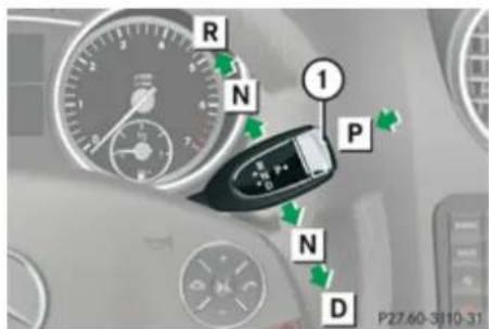
text_image
R N 1 P N D P27.60-3810-31Gearshift pattern for automatic transmission
① Button for selecting park position P
P Park position
R Reverse gear
N Neutral position
D Drive position
For more information on how to operate the gear selector lever, see "Automatic transmission" (> page 135).
▶ Make sure the automatic transmission is in park position P.
The transmission position indicator in the multifunction display should be on P (> page 137).
With SmartKey
▶ Do not depress the accelerator pedal.
▶ Gasoline engine: Turn the SmartKey in the starter switch to position 3 (> page 95) and release it.
The engine starts automatically.
▶ Diesel engine: Turn the SmartKey in the starter switch to position 2 (▷ page 95). Preglow indicator lamp 📄 in the instrument cluster comes on.
As soon as preglow indicator lamp goes out, turn the SmartKey in the starter switch to position 3 and release it. The engine starts automatically.
If the engine is at operating temperature, preglow indicator lamp 00 may not stay on and you can start the engine without preglowing.
With KEYLESS-GO
Warning!
As long as the SmartKey is in your vehicle, the vehicle can be started. Therefore, never leave children unattended in the vehicle, as
they could otherwise accidentally start the engine.
When leaving the vehicle, always take the SmartKey with you and lock the vehicle. Do not leave children unattended in the vehicle, or with access to an unlocked vehicle. A child's unsupervised access to a vehicle could result in an accident and/or serious personal injury.
You can start your vehicle without the SmartKey in the starter switch using the KEYLESS-GO start/stop button in the starter switch.
The SmartKey must be located in the vehicle.
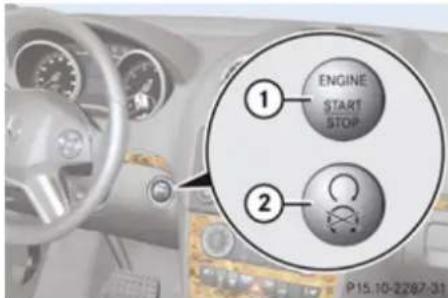
text_image
① ENGINE START STOP ② P15.10-2287-31KEYLESS-GO start/stop button
① USA only
② Canada only
Controls in detail
Driving and parking
▶ Make sure the KEYLESS-GO start/stop button is inserted in the starter switch.
If you wish to start the engine with the SmartKey instead of the KEYLESS-GO function, remove the KEYLESS-GO start/stop button from the starter switch and proceed as described in "With SmartKey" (▷ page 129).
▶ Depress the brake pedal during the starting procedure.
▶ Do not depress the accelerator pedal.
▶ Gasoline engine: Press the KEYLESS-GO start/stop button once.
The engine starts automatically.
▶ Diesel engine: Press the KEYLESS-GO start/stop button once.
The engine preglows and starts automatically.
If the engine is at operating temperature, the time the engine needs to preglow is reduced.
Starting difficulties
! Remember that extended starting attempts can drain the battery.
The engine does not start. You can hear the starter.
There could be a malfunction in the engine electronics or in the fuel supply system.
Carry out the following steps:
- If you are starting the engine with the SmartKey: Turn the SmartKey in the starter switch to position 0 and repeat the starting procedure.
- If you are starting the engine with KEYLESSGO: Close any doors that may be open to allow for better detection of the SmartKey.
or
▶ Remove the KEYLESS-GO start/stop button from the starter switch.
▶ Start the engine with the SmartKey as radio signals from another source may be interfering with the KEYLESS-GO function.
▶ Repeat the starting procedure.
If the engine does not start after several starting attempts:
▶ Contact an authorized Mercedes-Benz Center or call Roadside Assistance.
The engine does not start. You cannot hear the starter.
The battery may not be sufficiently charged.
▶ Get a jump start (▷ page 410).
If the engine will not start despite a jump start:
▶ Contact an authorized Mercedes-Benz Center or call Roadside Assistance.
The starter has been exposed to excessive temperatures.
▶ Let the starter cool for about two minutes.
▶ Repeat the starting procedure.
If the engine does not start after several starting attempts:
▶ Contact an authorized Mercedes-Benz Center or call Roadside Assistance.
Controls in detail
Driving and parking
Driving off

Warning!
On slippery road surfaces, never downshift in order to obtain braking action. This could result in drive wheel slip and reduced vehicle control. Your vehicle's ABS will not prevent this type of loss of control.
! Do not run cold engine at high engine speeds. Running a cold engine at high engine speeds may shorten the service life of the engine. This is not covered by the Mercedes-Benz Limited Warranty.
! If you hear a warning signal and the message Release Parking Brake appears in the multifunction display when driving off, you have forgotten to release the parking brake.
Release the parking brake.
! Avoid spinning of a drive wheel. This may cause serious damage to the drivetrain which is not covered by the Mercedes-Benz Limited Warranty.
! Simultaneously depressing the accelerator pedal and applying the brakes reduces engine performance and causes
premature brake and drivetrain wear which is not covered by the Mercedes-Benz Limited Warranty.
Once the vehicle is in motion, the automatic central locking system engages and the locking knobs in the doors move down.
The automatic door lock feature can be deactivated (▷ page 163).
Automatic transmission

Warning!
It is dangerous to shift the automatic transmission out of park position P or neutral position N if the engine speed is higher than idle speed. If your foot is not firmly on the brake pedal, the vehicle could accelerate quickly forward or in reverse. You could lose control of the vehicle and hit someone or something. Only shift into gear when the engine is idling normally and when your right foot is firmly on the brake pedal.
! Only shift the automatic transmission into reverse gear R or park position P when the
vehicle is stopped. Otherwise the automatic transmission could be damaged.
▶ Depress the brake pedal.
The gear selector lever can now be used.
▶ Shift the automatic transmission into drive position D or reverse gear R.
i Shifting the automatic transmission out of park position P is only possible with the brake pedal depressed.
Without the brake pedal depressed, the gear selector lever can be moved up or down, but the parking pawl remains engaged, not allowing shifting to occur.
▶ Wait for the gear selection process to complete before setting the vehicle in motion.
▶ Release the brake pedal.
▶ If engaged, release the parking brake.
▶ Carefully depress the accelerator pedal.
After a cold start, the automatic transmission shifts at a higher engine revolution. This allows the catalytic converter (gasoline engine) or the oxidation catalyst (diesel engine) to reach its operating temperature earlier.
Controls in detail
Driving and parking
For more information on driving, see “Driving instructions” (▷ page 299).
For information on off-road driving, see "Off-road driving" (▷ page 303).
Problems while driving
The engine runs erratically and misfires
• Gasoline engine: An ignition cable may be damaged.
• The engine electronics may not be operating properly.
- Gasoline engine: Unburned gasoline may have entered the catalytic converter and damaged it.
▶ Give very little gas.
▶ Have the problem checked at an authorized Mercedes-Benz Center as soon as possible.
The coolant temperature is above 248°F (120°C)
The coolant is too hot and is no longer cooling the engine.
▶ Stop the vehicle in a safe location as soon as possible.
▶ Turn off the engine immediately.
▶ Allow the engine and coolant to cool off.
▶ Check the coolant level and add coolant if necessary (▷ page 271).
In case of accident
If the vehicle is leaking fuel:
▶ Do not start the engine under any circumstances.
▶ Exit the vehicle at a safe distance from the roadway.
▶ Notify local fire and/or police authorities.
If the extent of the damage cannot be determined:
▶ Contact an authorized Mercedes-Benz Center or call Roadside Assistance.
If no damage on major assemblies, fuel system, and engine mount can be determined:
▶ Start the engine in the usual manner.
Parking
Warning!
Do not park this vehicle in areas where combustible materials such as grass, hay or leaves can come into contact with the hot exhaust system, as these materials could be ignited and cause a vehicle fire.
To reduce the risk of serious personal injury, or damage to the vehicle or the vehicle drivetrain, as a result of vehicle movement, always do the following before turning off the engine and leaving the vehicle:
- Keep right foot on the brake pedal.
- Engage the parking brake.
- Shift the automatic transmission into park position P.
- Slowly release the brake pedal.
- When parked on an incline, always turn the front wheels towards the road curb.
- Turn the SmartKey in the starter switch to position 0 and remove the SmartKey
from the starter switch, or press the KEYLESS-GO start/stop button.
• Take the SmartKey with you and lock the vehicle when leaving.
Parking brake

Warning!
Engaging the parking brake while the vehicle is in motion can cause the rear wheels to lock up. You could lose control of the vehicle and cause an accident. In addition, the vehicle's brake lights do not light up when the parking brake is engaged.

Warning!
When leaving the vehicle, always remove the SmartKey from the starter switch, take it with you, and lock the vehicle. Do not leave children unattended in the vehicle, or with access to an unlocked vehicle. Children could release the parking brake and/or shift the automatic transmission out of park position P, either of which could result in an accident and/or serious personal injury.
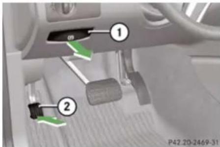
text_image
Diagram of car interior showing two labeled parts (① and ②) with directional arrows indicating movement or flow.① Release handle
② Parking brake pedal
▶ Releasing: Pull on release handle ①. When the ignition is switched on or the engine is running, the brake warning lamp BRAKE (USA only) or ① (Canada only) in the instrument cluster goes out.
▶ Engaging: Step firmly on parking brake pedal ②.
When the engine is running, the brake warning lamp BRAKE (USA only) or (1) (Canada only) in the instrument cluster comes on.
Turning off the engine

Warning!
Do not turn off the engine before the vehicle has come to a complete stop. With the engine not running, there is no power assistance for the brake and steering systems. In this case, it is important to keep in mind that a considerably higher degree of effort is necessary to brake and steer the vehicle.
If the engine cannot be turned off as described, see "Emergency engine shutdown" (▷ page 417).
▶ Shift the automatic transmission into park position P.
▶ Engage the parking brake.
i Always engage the parking brake in addition to shifting the automatic transmission into park position P. When parked on an incline, also turn the front wheels towards the road curb.
i Observe instructions if you want the automatic transmission to remain in
Controls in detail
Driving and parking
neutral position N, see “Remaining in neutral position N” (▷ page 136).
With SmartKey
▶ Turn the SmartKey in the starter switch to position 0.
▶ Remove the SmartKey from the starter switch.
The immobilizer is activated.
If you turn off the engine using the SmartKey, and remove the SmartKey from the starter switch or open a front door, the automatic transmission will shift into park position P automatically.
Warning!
Keep in mind that turning off the engine alone only will shift the automatic transmission into neutral position N automatically.
Always shift the automatic transmission into park position P before turning off the engine.
Otherwise the vehicle could roll away which could result in an accident and/or serious personal injury.
With KEYLESS-GO
Press the KEYLESS-GO start/stop button. With the driver's door closed, the starter switch is now in position 1. With the driver's door opened, the starter switch is set to position 0, same as the SmartKey removed from the starter switch ( page 95).
If you turn off the engine using the KEYLESS-GO start/stop button and open a front door, the automatic transmission will shift into park position P automatically.
Warning!
Keep in mind that turning off the engine alone only will shift the automatic transmission into neutral position N automatically.
Always shift the automatic transmission into park position P before turning off the engine.
Otherwise the vehicle could roll away which could result in an accident and/or serious personal injury.
In an emergency you can turn off the engine while driving by pressing and holding the KEYLESS-GO start/stop button for approximately 3 seconds.
If you have started the engine with the KEYLESS-GO start/stop button and cannot turn it off as described above:
▶ Remove the KEYLESS-GO start/stop button from the starter switch.
▶ Insert the SmartKey into the starter switch. The engine turns off. The starter switch is in position 0 (▷ page 95).
Controls in detail
Automatic transmission
Automatic transmission
Introduction
For information on driving with an automatic transmission, see "Driving and parking" (▷ page 128).

Warning!
Make sure absolutely no objects are obstructing the pedals' range of movement. Keep the driver's footwell clear of all obstacles. If there are any floormats or carpets in the footwell, make sure the pedals still have sufficient clearance.
During sudden driving or braking maneuvers the objects could get caught between the pedals. You could then no longer brake or accelerate. This could lead to accidents and injury.
! Allow engine to warm up under low load use. Do not place full load on the engine until the operating temperature has been reached.
Avoid spinning of a drive wheel for an extended period when driving off on slippery road surfaces.
This may cause serious damage to the engine and the drivetrain which is not
covered by the Mercedes-Benz Limited Warranty.
During the brief warm-up, transmission upshifting is delayed. This allows the catalytic converter (gasoline engine) or oxidation catalyst (diesel engine) to heat up more quickly to operating temperature.
Gear selector lever
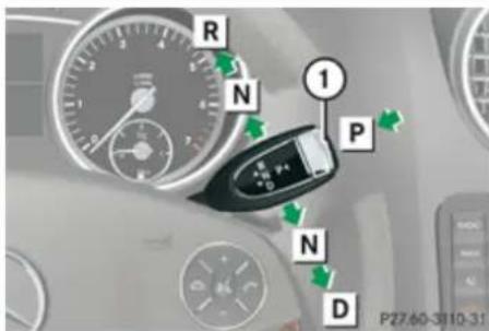
text_image
R N 1 P N D P27.60-3810-31Gearshift pattern for automatic transmission
① Button for selecting park position P
P Park position
R Reverse gear
N Neutral position
D Drive position

Warning!
It is dangerous to shift the automatic transmission out of park position P or neutral position N if the engine speed is higher than idle speed. If your foot is not firmly on the brake pedal, the vehicle could accelerate quickly forward or in reverse. You could lose control of the vehicle and hit someone or something. Only shift into gear when the engine is idling normally and when your right foot is firmly on the brake pedal.
! Only shift the automatic transmission into reverse gear R or park position P when the vehicle is stopped. Otherwise the automatic transmission could be damaged.
! The vehicle must be stopped when you shift the automatic transmission
- directly between drive position D and reverse gear R
- directly between reverse gear R and drive position D
• directly into park position P
Otherwise the automatic transmission could be damaged.
Controls in detail
Automatic transmission
When trying to free a vehicle stuck in mud or snow, see “Rocking the vehicle” (▷ page 139).
i Shifting the automatic transmission out of park position P is only possible with the brake pedal depressed.
Without the brake pedal depressed, the gear selector lever can be moved up or down, but the parking pawl remains engaged, not allowing shifting to occur.
The gear selector lever always returns to its original position.
The current transmission position P, R, N, or D appears in the multifunction display (▷ page 137).
Shifting into park position P
▶ With the vehicle at a standstill, press button ① on the gear selector lever to select park position P.
SmartKey: When you turn off the engine using the SmartKey, and remove the SmartKey from the starter switch or open a front door, the automatic transmission will shift into park position P automatically.
KEYLESS-GO: When you turn off the engine using the KEYLESS-GO start/stop button and
open a front door, the automatic transmission will shift into park position P automatically.
Warning!
Keep in mind that turning off the engine alone only will shift the automatic transmission into neutral position N automatically.
Always shift the automatic transmission into park position P before turning off the engine.
Otherwise the vehicle could roll away which could result in an accident and/or serious personal injury.
i Moving the gear selector lever up or down shifts the automatic transmission out of park position P.
Shifting into neutral position N
▶ With the vehicle at a standstill, depress the brake pedal and move the gear selector lever up or down to the resistance point to select neutral position N.
When you turn off the engine, the automatic transmission will shift into neutral position N automatically.
SmartKey: Removing the SmartKey from the starter switch or opening a front door after turning off the engine will shift the automatic transmission into park position P automatically.
KEYLESS-GO: Opening a front door after turning off the engine will shift the automatic transmission into park position P automatically.
Remaining in neutral position N
If you want the automatic transmission to remain in neutral position N, e.g. when taking the vehicle through an automatic conveyor-type car wash, observe the following instructions:
Warning!
When leaving the SmartKey in the starter switch, do not leave children unattended in the vehicle. It is possible for children to switch on the ignition which could result in unsupervised use of vehicle equipment. Unsupervised use of vehicle equipment could result in an accident and/or serious personal injury.
Controls in detail
Automatic transmission
With SmartKey:
▶ Make sure the ignition is switched on.
▶ With the vehicle at a standstill, depress the brake pedal and keep it pressed.
▶ Shift the automatic transmission into neutral position N.
▶ Release the brake pedal.
▶ If engaged, release the parking brake.
▶ Switch off the ignition and leave the SmartKey in the starter switch.
With KEYLESS-GO:
▶ Make sure the ignition is switched on.
▶ With the vehicle at a standstill, depress the brake pedal and keep it pressed.
▶ Shift the automatic transmission into park position P.
▶ Release the brake pedal.
Remove the KEYLESS-GO start/stop button from the starter switch.
▶ Insert the SmartKey into the starter switch.
▶ Switch on the ignition.
▶ Depress the brake pedal and keep it pressed.
▶ Shift the automatic transmission into neutral position N.
▶ Release the brake pedal.
▶ If engaged, release the parking brake.
▶ Switch off the ignition and leave the SmartKey in the starter switch.
Shifting into reverse gear R
▶ With the vehicle at a standstill, depress the brake pedal and move the gear selector lever up past the resistance point to select reverse gear R.
Shifting into drive position D
▶ With the vehicle at a standstill, depress the brake pedal and move the gear selector lever down past the resistance point to select drive position D.
Shifting procedure
The automatic transmission selects individual gears automatically, depending on:
- the selected gear range (▷ page 139)
• the position of the accelerator pedal
• the vehicle speed
With drive position D selected, you can influence transmission shifting by limiting or extending the gear range.
Transmission positions
The current transmission position appears in the multifunction display.
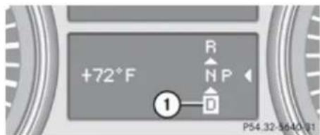
text_image
+72°F R N P ① D P54.32-5640-81① Transmission position indicator
Controls in detail
Automatic transmission
If the current transmission position does not appear in the multifunction display due to a malfunction, for example, make sure that the automatic transmission is in the desired position:
▶ Shift the automatic transmission into drive position D.
▶ Do not limit the gear range.
▶ Drive off carefully.
Effect
P Park position
Shift the automatic transmission into park position P only when the vehicle is stopped. The park position is not intended to serve as a brake when the vehicle is parked. Rather, the driver should always engage the parking brake in addition to shifting the automatic transmission into park position P to secure the vehicle. If the vehicle's electrical system is malfunctioning, the automatic transmission could remain locked in park position P.
Have the vehicle's electrical system checked as soon as possible at an authorized Mercedes-Benz Center.
R Reverse gear
Shift the automatic transmission into reverse gear R only when the vehicle is stopped.
Effect
N Neutral position
No power is transmitted from the engine to the drive axle. When the brakes are released, the vehicle can be moved freely (pushed or towed).
To avoid damage to the transmission, never shift the automatic transmission into neutral position N while driving.
Exception: If the ESP ^® is deactivated or malfunctioning, shift the automatic transmission into neutral position N if the vehicle is in danger of skidding.
! Coasting the vehicle, or driving for any other reason with the automatic transmission in neutral position N can result in transmission damage that is not covered by the Mercedes-Benz Limited Warranty.
D Drive position
Controls in detail
Automatic transmission
Effect
The automatic transmission shifts automatically. All forward gears are available.
Driving tips
Kickdown
Use the kickdown when you want maximum acceleration.
▶ Fully depress the accelerator pedal. Depending on the engine speed the automatic transmission shifts into a lower gear.
Canada vehicles only:
▶ Depress the accelerator pedal past the point of resistance to use the kickdown.
Rocking the vehicle
Rocking the vehicle by shifting the automatic transmission directly between drive position D and reverse gear R can help free a vehicle stuck in mud or snow. The engine control system of this vehicle electronically limits directly shifting the automatic transmission between drive position D and reverse gear R to very low speeds, i.e. approximately 5 mph (9 km/h). To shift the automatic transmission directly between drive position D and reverse gear R, move the gear selector lever past the resistance point up or down.
Working on the vehicle
Warning!
When working on the vehicle, engage the parking brake and shift the automatic transmission into park position P. Otherwise the vehicle could roll away which could result in an accident and/or serious personal injury.
Towing a trailer
When you tow a trailer, shift into a lower gear range manually if the automatic transmission hunts between gears on inclines.
A lower gear range and reduction of speed reduces the potential to overload or to overheat the engine.
For more information on trailer towing, see the "Operation" section ( page 310).
Gear ranges
With the automatic transmission in drive position D, you can limit or extend the gear range, see "One-touch gearshifting" (▷ page 140).
The current gear range appears in the multifunction display.
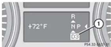
text_image
+72°F R N P D3 1 P54.32-56.17/91① Gear range indicator
Controls in detail
Automatic transmission
| Effect | |
| 3 | With this selection you can use the braking effect of the engine. |
| 2 | Allows the use of engine's braking power when drivingon steep downgradesin mountainous regionsunder extreme operating conditions |
| 1 | For maximum use of engine's braking effect on very steep or lengthy downgrades. |
One-touch gearshifting
With the automatic transmission in drive position D, you can limit or extend the gear range using the steering wheel gearshift control.
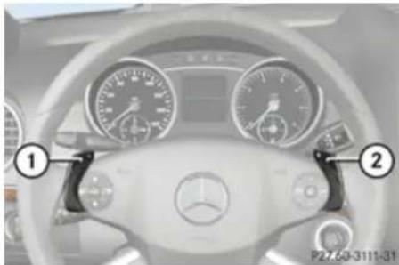
natural_image
Interior view of a Mercedes-Benz car dashboard and steering wheel (no visible text or symbols)Steering wheel gearshift control
① Limiting gear range
Downshift (in manual program mode M)
② Extending gear range
Upshift (in manual program mode M)
i You cannot shift with the steering wheel gearshift control when the automatic transmission is in park position P, neutral position N, or reverse gear R.
Limiting gear range
Warning!
On slippery road surfaces, never downshift in order to obtain braking action. This could result in drive wheel slip and reduced vehicle control. Your vehicle's ABS will not prevent this type of loss of control.
▶ Briefly pull left gearshift control ①.
The automatic transmission will shift into the next lower gear as permitted by the shift program. This action simultaneously limits the gear range of the automatic transmission.
To avoid overrevving the engine when downshifting, the automatic transmission will not shift into a lower gear if the engine's maximum speed would be exceeded.
Extending gear range
▶ Briefly pull right gearshift control ②.
The automatic transmission will shift into the next higher gear as permitted by the shift program. This action simultaneously extends the gear range of the automatic transmission.
Controls in detail
Transfer case
If you press on the accelerator pedal when the engine has reached the revolution limit of the current gear range, the automatic transmission will upshift beyond any gear range limit selected.
Canceling gear range limit
▶ Pull and hold right gearshift control ② until the gear range indicator disappears from the multifunction display. The automatic transmission will shift from the current gear range directly into gear range D.
Shifting into optimal gear range
▶ Pull and hold left gearshift control ①. The automatic transmission will select the gear range suited for optimal acceleration and deceleration automatically. This will involve shifting down one or more gears.
Emergency operation (limp-home mode)
If vehicle acceleration becomes less responsive or sluggish or the automatic transmission no longer shifts, the automatic transmission is most likely operating in limphome (emergency operation) mode. In this mode only second gear and reverse gear R can be selected.
▶ Stop the vehicle in a safe location.
▶ Shift the automatic transmission into park position P.
▶ Turn off the engine.
▶ Wait at least 10 seconds before restarting.
▶ Restart the engine.
▶ Shift the automatic transmission into drive position D (for second gear) or reverse gear R.
▶ Have the automatic transmission checked at an authorized Mercedes-Benz Center as soon as possible.
Transfer case
The vehicle is equipped with all-wheel drive (4MATIC). Both the front and rear axles are powered at all times when the vehicle is being operated.
! Only conduct operational or performance tests on a two-axle dynamometer. If such tests are necessary, contact an authorized Mercedes-Benz Center. You could otherwise seriously damage the brake system or the transfer case which is not covered by the Mercedes-Benz Limited Warranty.
Because the ESP® operates automatically, the engine and ignition must be shut off (SmartKey in starter switch position 0 or 1 or KEYLESS-GO start/stop button in position 0 or 1) when the parking brake is being tested on a brake test dynamometer. Such testing should be no longer than 10 seconds.
Active braking action through the ESP® may otherwise seriously damage the brake system which is not covered by the Mercedes-Benz Limited Warranty.
Controls in detail
Transfer case
LOW RANGE mode (Canada only)
The LOW RANGE mode is available on vehicles with enhanced off-road package. In the following situations you should switch to the LOW RANGE mode:
• during off-road driving
• before driving through water
- when towing up or down on steep gradients
With LOW RANGE selected, the engine's power delivery and the shifting behavior of the automatic transmission are adjusted. Furthermore, the ABS, the ESP ^ , and the 4-ETS functions especially adapted to off-road travel are activated.
For more information on off-road driving, see "Off-road driving" (▷ page 303).
For information on driving safety systems during LOW RANGE mode, see “Driving safety systems” (▷ page 75).
Gear ranges
There are two possible settings.
| HIGH RANGE | Road position for all normal driving situations. (LOW RANGE mode off) |
| LOW RANGE | Off-road position for traveling on rough terrain. (LOW RANGE mode on) Also use the off-road position when driving on-road on steep gradients, especially when towing a trailer. LOW RANGE acts by raising the engine's gear ratio. The vehicle travels at roughly third the speed compared to when in HIGH RANGE position, leading to an increase in the engine's drive power. |

Warning!
Always wait until the procedure of shifting from HIGH RANGE to LOW RANGE - and from LOW RANGE to HIGH RANGE - has
been entirely completed. During this procedure do not turn off the engine or shift the automatic transmission into another gear.
If you do not wait until the shifting procedure has been entirely completed then it might not be correctly performed. The transfer case might be in neutral, thus interrupting the transfer of power between the engine and the drive axle.
The vehicle is then freely movable, even if a gear has been selected, and could unintentionally be set into motion – particularly on up – or downhill grades. This could lead to an accident and cause injury to yourself and others.
Please observe related messages appearing in the multifunction display.
Controls in detail
Transfer case
Switching LOW RANGE mode
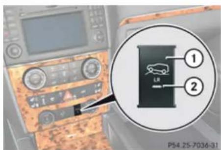
text_image
1 LR 2 P54.25-7036-31① LOW RANGE switch
② Indicator lamp
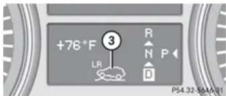
text_image
+76°F 3 LR R N P D P54.32-5649-01③ LOW RANGE indicator
Switching LOW RANGE mode on (switching from HIGH RANGE to LOW RANGE)
! The shifting procedure can only be performed when the following conditions are met:
• The engine is running.
- The automatic transmission is in neutral position N.
• The vehicle speed does not exceed 25 mph (40 km/h).
There is no reset to HIGH after the ignition has been switched off.
▶ Press LOW RANGE switch ①.
Indicator lamp ② flashes.
If the system senses that all conditions are met, it will switch from HIGH RANGE to LOW RANGE. A chime sounds and LOW RANGE indicator ③ appears in the multifunction display.
Indicator lamp ② on LOW RANGE switch ① comes on continuously, indicating that the LOW RANGE mode has been activated.
You can cancel the procedure by pressing the LOW RANGE switch again while the indicator lamp is flashing.
Switching LOW RANGE mode off (switching from LOW RANGE to HIGH RANGE)
! The shifting procedure can only be performed when the following conditions are met:
• The engine is running.
• The automatic transmission is in neutral position N.
• The vehicle speed does not exceed 43 mph (70 km/h).
There is no reset to LOW after the ignition has been switched off.
▶ Press LOW RANGE switch ①.
Indicator lamp ② flashes.
If the system senses that all conditions are met, it will switch from LOW RANGE to HIGH RANGE. A chime sounds and LOW RANGE indicator ③ disappears from the multifunction display.
▶▶
Controls in detail
Differential locks (Canada only)
Indicator lamp ② on LOW RANGE switch ① goes out, indicating that the LOW RANGE mode has been deactivated.
You can cancel the procedure by pressing the LOW RANGE switch again while the indicator lamp is flashing.
For messages in the multifunction display, see the "Practical hints" section (▷ page 352).
Differential locks (Canada only)
Vehicles with enhanced off-road package are equipped with automatic locks for the center and rear axle differential to improve vehicle traction.
The center differential compensates for differences in wheel rotation between the front and rear axle.
The rear axle differential compensates differences between the rear wheels.
At the front axles, the 4-ETS system compensates for any traction problems.
For more information on off-road driving, see "Off-road driving" (▷ page 303).
A few words about differentials and differential locks
When a vehicle negotiates a turn, wheels on the outside of the curve must travel farther and rotate faster than the inside wheels. The differential, the operation of a set of gears that allows the powered wheels in a vehicle to turn at different speeds, makes this essential function possible.
The drawback is that the differential also sends most of the engine's power to the wheel with the least load or strain on it. For example, if one of a vehicle's powered wheels sits on a patch of snow and spins because there is no traction, all of the engine's power will go to that wheel because the power will take the path of least resistance. Meanwhile, the opposite wheel, sitting on dry pavement where it could get enough grip to start the vehicle moving, sits idle because it receives no power.
The 4-ETS addresses this problem and provides for good control and steering ability by automatically slowing the slipping wheel and thus increasing the power to the other non-slipping drive wheels to get the vehicle moving. The ESP® and the 4-ETS in this vehicle feature such intelligent limited-slip differential technology, ideally suited for on-road and light off-road driving. Transfer case position LOW (▶ page 142) also enhances off-road driving capabilities.
More extreme off-road conditions may call for another solution, engaging a differential lock or preventing the differential from operating altogether. This vehicle comes with two differential locks: transfer case (center) and rear. Each can be engaged simply by operating the rotary switch located on the center console ( page 145). When the transfer case (center) differential is locked,
Controls in detail
Differential locks (Canada only)
the combined (or average) speed of the front wheels is identical to the combined rear wheel speed. When the rear differential is locked, both rear wheels turn at the same speed, independent of the individual torque. Please be aware that engaging the differential locks will significantly reduce the steering ability of the vehicle.
For your safety and the safety of others and to prevent damage to the vehicle, the differential locks must not be engaged when driving on paved roads. It is important to understand that during on-road/paved driving, differentials are absolutely necessary for providing the essential control and steering ability of the vehicle. The differential locks, therefore, must not be engaged when driving on paved roads and should only be used to the extent necessary to negotiate off-road conditions which cannot be handled by the systems (the 4-ETS, the ESP ^® , and the transfer case in LOW RANGE mode) this vehicle comes equipped with.
Switching differential locks
! If the differential locks are engaged, accelerate gently when setting the vehicle in motion.
Only operate the vehicle on a single axle dynamometer if the axle not being driven is jacked up or the associated propeller shaft is disconnected.
Otherwise the transmission could be damaged.
You can select between three locking modes.
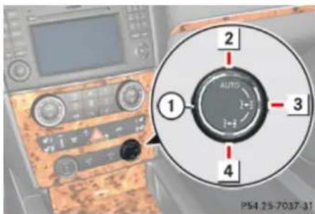
text_image
1 2 3 4 AUTO P54 25-7037-31Rotary switch for differential locks
① Rotatable outer adjustment ring with indicator lamp
2 AUTO mode: center differential is automatically locked
3 Center differential is completely locked
4 Center and rear axle differential are completely locked
AUTO mode
The AUTO mode is adequate for most driving situations since the center differential is locked and released as required.
At speeds up to 19 mph (30 km/h), it is possible to manually lock the differential locks for driving on rough terrain.
▶ Start the engine.
The center differential lock is in AUTO mode. The indicator lamp on adjustment ring ① above symbol AUTO is on.
Controls in detail
Differential locks (Canada only)
Center and rear axle differential locks

Warning!
Never drive on a paved surface with the center and rear axle differential locks manually engaged. Ability to steer the vehicle is greatly reduced when the differential locks are manually engaged, increasing the risk of an accident.
For safety reasons, the locks are automatically released at a vehicle speed above 31 mph (50 km/h). Nevertheless, you should only manually lock the differential if absolutely necessary because engaged locks will restrict the vehicle drivetrain while cornering and cause the vehicle to chatter. This could cause you to lose control of the vehicle and cause an accident.
! The differential locks must not be engaged manually when towing the vehicle or spinning the wheels.
The differential locks should only be engaged manually if traction is insufficient in AUTO mode.
The differential locks can be engaged in the sequence 3, 4 (▷ page 145) up to a speed of 19 mph (30 km/h).
Engage differential locks:
• for off-road driving
• for driving through water
- when driving on deep snow and icy or fouled surfaces
▶ Start the engine.
To select the desired locking mode, rotate adjustment ring ① to position ③ or ④ (▷ page 145).
The indicator lamp on adjustment ring ① at the respective symbol comes on.
A message indicating that the respective differential is completely locked appears in the multifunction display.

text_image
OFF-road NE 5 PS4 32-0547-31Example illustration
⑤ Center differential completely locked
! If the differential locks have been manually engaged, the tires will scuff on the road surface when cornering because the
differences between the individual wheel rotation speeds will not be compensated for.
The differential locks are reset to AUTO mode after the ignition has been switched off for longer than 10 seconds.
Controls in detail
Instrument cluster
Instrument cluster
Introduction
For a full view illustration of the instrument cluster, see "Instrument cluster" (▷ page 32).

Warning!
No messages will be displayed if either the instrument cluster or the multifunction display is inoperative.
As a result, you will not be able to see information about your driving conditions, such as speed or outside temperature, warning/indicator lamps, malfunction/warning messages or the failure of any systems. Driving characteristics may be impaired.
If you must continue to drive, please do so with added caution. Contact an authorized Mercedes-Benz Center as soon as possible.
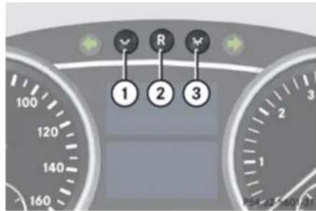
text_image
1 2 3① To dim instrument cluster illumination
② Reset button
③ To brighten instrument cluster illumination
Activating the instrument cluster
The instrument cluster is activated when you
- open a front door
- switch on the ignition
- press reset button ②
- switch on the exterior lamps
Opening a front door or pressing the reset button without switching on the ignition or the exterior lamps activates the instrument cluster illumination only for 30 seconds.
For information on changing the instrument cluster settings, e.g. the language, see (▷ page 158).
Adjusting the instrument cluster illumination
i The instrument cluster illumination is dimmed or brightened automatically to suit ambient light conditions.
The instrument cluster illumination will also be adjusted automatically when you switch on the vehicle's exterior lamps.
With the exterior lighting switched on, the brightness of the switches in the center console will also be adjusted when using button ① or ③.
To brighten illumination: Press and hold button ③ until the desired level of illumination is reached.
▶ To dim illumination: Press and hold button ① until the desired level of illumination is reached.
Controls in detail
Control system
Resetting trip odometer
▶ Make sure you are viewing the standard display (▷ page 152) in the multifunction display.
▶ Press and hold the reset button in the instrument cluster (▷ page 147) until the trip odometer is reset.
Tachometer
The red marking on the tachometer (▷ page 35) denotes excessive engine speed.
! Avoid driving at excessive engine speeds, as it may result in serious engine damage that is not covered by the Mercedes-Benz Limited Warranty.
To help protect the engine, the fuel supply is interrupted if the engine is operated within the red marking.
Control system
Introduction
The control system is activated as soon as the starter switch is in position 1 (▷ page 95).
The control system enables you to call up information about your vehicle and to change vehicle settings.
For example, you can use the control system to find out when your vehicle is next due for maintenance service, to set the language for messages in the instrument cluster display, and much more.
Warning!
A driver's attention to the road and traffic conditions must always be his/her primary focus when driving.
For your safety and the safety of others, selecting features through the multifunction steering wheel should only be done by the driver when traffic and road conditions permit it to be done safely.
Bear in mind that at a speed of just 30 mph (approximately 50 km/h), your vehicle is covering a distance of 44 feet (approximately 14 m) every second.
The control system relays information to the multifunction display.
Multifunction steering wheel
The displays in the multifunction display and the settings in the control system are controlled by the buttons on the multifunction steering wheel.
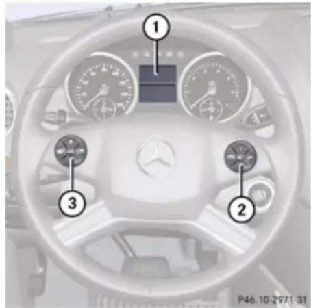
text_image
Diagram of a car dashboard with numbered parts for identification and adjustment, showing controls and gauges.Controls in detail
Control system
| 1 | Multifunction display |
| 2 | Press buttonto take a callto dial6to redial6to end a callto reject an incoming call |
| Press button+ to select submenus in theSettings menuto set valuesto set the volume | |
| Press buttonto turn Voice Control Systemon7, see separate operatinginstructions | |
| 3 | Press buttonto select next or previous menu |
Press button briefly
| to move within a menu | |
| Within Audio/DVD menu to select previous or next track, scene or stored station. | |
| Within Telephone menu to switch to the phone book and select a name or number. |
Press and hold button
| Within Audio/DVD menu to select previous or next track with quick search or to select previous or next station in station list or wave band. | |
| Within Telephone menu to start the quick search in the phone book. |
Press button
| OFF1 | to turn Voice Control System off7, see separate operating instructions |
Depending on the selected menu, pressing the buttons on the multifunction steering wheel will alter what appears in the multifunction display.
The information available in the multifunction display is arranged in menus and accompanying functions and submenus.
The individual functions are then found within the relevant menu (radio or CD operations under Audio/DVD menu, for example). These functions serve to call up relevant information or to customize the settings for your vehicle.
It is helpful to think of the menus, and the functions within each menu, as being arranged in a circular pattern.
▶ Press button 📋 or 📋 repeatedly to pass through each menu one after the other.
▶ Press button 🧑 or 🏠 repeatedly to pass through each function display, one after the other, in the current menu.
In the Settings menu, instead of functions, you will find a number of submenus for calling up and changing settings. For instructions on
Controls in detail
Control system
using these submenus, see "Settings menu" (▷ page 157).
The number of menus available in the system depends on which optional equipment is installed in your vehicle.
② Main odometer
③ Transmission position/gear range indicator
④ Outside temperature or digital speedometer
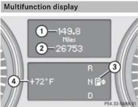
text_image
Multifunction display ① 149.8 Miles ② 26753 ③ +72°F R N P# D P54.32-565A-01① Trip odometer
For more information on menus displayed in the multifunction display, see "Menus and submenus" (▷ page 151).
Menus and submenus
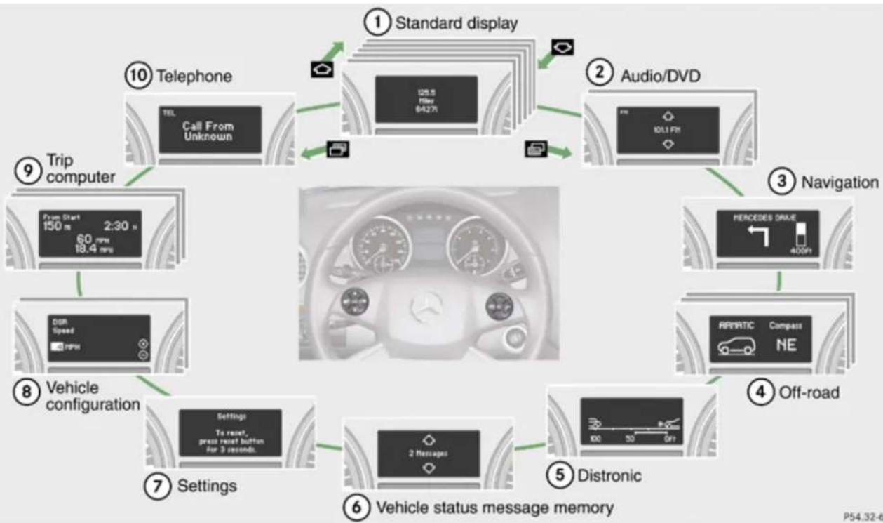
flowchart
graph TD
    A["Standard display"] --> B["Audio/DVD"]
    B --> C["Navigation"]
    C --> D["Off-road"]
    D --> E["Distronic"]
    E --> F["Vehicle status message memory"]
    F --> G["Settings"]
    G --> H["Vehicle configuration"]
    H --> I["Trip computer"]
    I --> J["Telephone"]
    J --> K["Call From Unknown"]
    K --> L["From Start 150 m 2:30 h 18.4 mph"]
    L --> M["DDR Speed RPM"]
    M --> N["Settings To reset, press reset button for 3 seconds"]
    N --> O["Navigation"]
    O --> P["FERCEDES DRIVE 400/91"]
    P --> Q["Off-road"]
Controls in detail
Control system
The headings used in the menus table are designed to facilitate navigation within the system and are not necessarily identical to those shown in the multifunction display. The first function displayed in each menu will automatically show you which part of the system you are in.
| Function | |
| 1 | Standard display menu(▷ page 152) |
| 2 | Audio/DVD menu (▷ page 153) |
| 3 | Navigation menu (▷ page 155) |
| 4 | Off-road menu (▷ page 155) |
| 5 | Distronic menu (▷ page 156) |
| 6 | Vehicle status message memory ^8 menu (▷ page 156) |
| 7 | Settings menu (▷ page 157) |
| 8 | Vehicle configuration menu(▷ page 164) |
| Function | |
| 9 | Trip computer menu (▷ page 165) |
| 10 | Telephone menu (▷ page 167) |
Standard display menu
In the standard display, the main odometer and the trip odometer appear in the multifunction display.
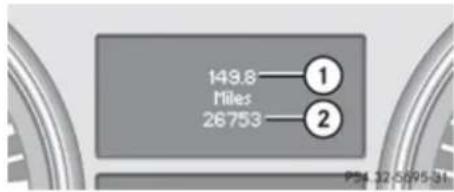
text_image
149.8 Hiles 26753 ① ② P# 32-0095-31Standard display
① Trip odometer
② Main odometer
If you see another display, press button or repeatedly until the standard display appears.
▶ Press button △ or ▼ to select the functions in the Standard display menu.
The following functions are available:
- Checking tire inflation pressure (▷ page 281)
- Checking coolant temperature (▷ page 152)
- Calling up digital speedometer or outside temperature (▷ page 153)
- Calling up maintenance service indicator display (▷ page 317)
Checking coolant temperature
Warning!
Driving when your engine is overheated can cause some fluids which may have leaked into the engine compartment to catch fire. You could be seriously burned.
Steam from an overheated engine can cause serious burns which can occur just by opening the engine hood. Stay away from the engine if you see or hear steam coming from it.
Stop the vehicle in a safe location away from other traffic. Turn off the engine, get
Controls in detail
Control system
out of the vehicle and do not stand near the vehicle until the engine has cooled down.
▶ Press button or repeatedly until the coolant temperature appears in the multifunction display.
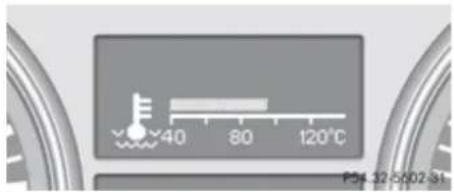
text_image
40 80 120°C P34-12-002 StDuring severe operating conditions, e.g. stop-and-go traffic, the coolant temperature may rise close to 248°F (120°C).
! Excessive coolant temperature triggers a warning in the multifunction display. The engine should not be operated with a coolant temperature above 248°F (120°C). Doing so may cause serious engine damage which is not covered by the Mercedes-Benz Limited Warranty.
Calling up digital speedometer or outside temperature
You can select whether the digital speedometer or the outside temperature appears in the multifunction display (▷ page 159).
Warning!
The outside temperature indicator is not designed to serve as an ice-warning device and is therefore unsuitable for that purpose.
Indicated temperatures just above the freezing point do not guarantee that the road surface is free of ice. The road may still be icy, especially in wooded areas or on bridges.
▶ Press button or repeatedly until the digital speedometer or the outside temperature appears in the multifunction display.
text_image
55 MPH P24 32 3614 38Digital speedometer

text_image
+72°F PS4.32-5615-31Outside temperature
Audio/DVD menu
The functions in the Audio/DVD menu operate the audio or video equipment which you have currently turned on.
If no audio equipment is currently turned on, the message AUDIO Off appears in the multifunction display.
▶▶
Controls in detail
Control system
The following functions are available:
- Selecting radio station (▷ page 154)
- Operating audio devices/audio media (▷ page 154)
- Operating video DVD (▷ page 155)
Selecting radio station
The HD-radio with SIRIUS satellite radio is treated as a radio application.
For more information on HD-radio with SIRIUS satellite radio, refer to separate COMAND system operating instructions.
Additional optional satellite radio equipment and a subscription to satellite radio service provider are required for satellite radio operation. Contact an authorized Mercedes-Benz Center for details and availability for your vehicle.
▶ Turn on the COMAND system and select radio. Refer to separate COMAND system operating instructions.
▶ Press button 📄 or 📋 repeatedly until the currently tuned station appears in the multifunction display.
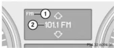
text_image
FM1—① ②—101.1 FM PS4 32 6094 31Example illustration
① Wave band setting and stored memory position
② Station frequency
▶ Select next or previous stored station: Press ▼ or △ briefly to select a stored station.
▶ Select next or previous station in the station list: Press and hold ↩ or ↗ to select a station.
▶ Select next or previous station in wave band (Only if no station list is available): Press and hold ↩ or ↗ to select a station.
You can only store new stations using the corresponding feature on the radio. Refer to separate COMAND system operating instructions.
You can also operate the radio in the usual manner.
Operating audio devices/audio media
▶ Turn on the COMAND system and select the audio device or audio media. Refer to separate COMAND system operating instructions.
▶ Press button 📋 or 📋 repeatedly until the Audio/DVD menu appears in the multifunction display.
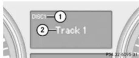
text_image
DISC1—① ②—Track 1 P34.32-6D95-31Example illustration
① Disc number
② Current track
▶ Selecting previous or next track: Press button or briefly.
▶ Selecting previous or next track: Press button or briefly.
▶ Selecting a track from the track list (quick search): Press and hold button or .
The current track does not appear during Audio AUX mode operation.
Operating video DVD
▶ Turn on the COMAND system and select DVD-Video. Refer to separate COMAND system operating instructions.
▶ Press button or repeatedly until the Audio/DVD menu appears in the multifunction display.
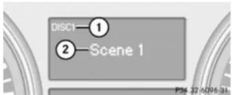
text_image
DISC1—① ②—Scene 1 P34.32 6096.31① Disc number
② Current scene
▶ Press button ↘ or ↗ to select a scene.
Navigation menu
The Navigation menu contains the functions needed to operate your navigation system.
▶ Press button 📄 or 📄 repeatedly until the Navigation menu appears in the multifunction display.
The message shown in the multifunction display depends on the status of the navigation system:
- With the COMAND system switched off, the message NAV off appears in the multifunction display.
- With the COMAND system switched on but route guidance not activated, the direction of travel and, if applicable, the name of the street currently traveled on appear in the multifunction display.
- With the COMAND system switched on and route guidance activated, the direction of travel and maneuver instructions appear in the multifunction display.
Please refer to the COMAND system operating instructions for instructions on how to activate the route guidance system.
Off-road menu
The Off-road menu displays the messages for air suspension, differential locks and the direction into which you are currently driving.
▶ Press button or repeatedly until one of the following messages appears in the multifunction display.
Vehicles with air suspension:
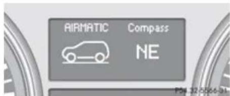
text_image
AIRMATIC Compass NE PS4 32-5506-31Vehicles with air suspension and differential locks:
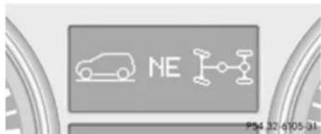
text_image
NE 954.32 6105-34For information on air suspension, see "Air suspension program" (▷ page 185).
For information on differential locks, see "Differential locks" (▷ page 144).
▶▶
Controls in detail
Control system
For information on the compass, see "Vehicle submenu" (▷ page 163) and "Compass" (▷ page 260).
Distronic menu
Use the Distronic menu to display the current settings for your Distronic system. The information shown in the multifunction display depends on whether the Distronic system is activated or deactivated.
Please refer to the "Driving systems" section of this manual (▷ page 172) for instructions on how to activate Distronic.
Vehicle status message memory menu
Use the Vehicle status message memory menu to scan malfunction and warning messages that may be stored in the memory. Such messages appear in the multifunction display and are based on conditions or system status the vehicle's system has recorded.
The Vehicle status message memory menu only appears if messages have been stored.
Warning!
Malfunction and warning messages are only indicated for certain systems and are intentionally not very detailed. The malfunction and warning messages are simply a reminder with respect to the operation of certain systems. They do not replace the owner's and/or driver's responsibility to maintain the vehicle's operating safety. Have all required maintenance and safety checks performed on the vehicle. Bring the vehicle to an authorized Mercedes-Benz Center to address the malfunction and warning messages.
▶ Press button 📄 or 📋 repeatedly until the Vehicle status message memory menu appears in the multifunction display. If conditions have occurred causing status messages to be recorded, the number of messages appears in the multifunction display:
text_image
2 Messages Page 32-009341▶ Press button ↻ or ▼.
The stored messages will now be displayed in the order in which they have occurred. For malfunction and warning messages, see "Vehicle status messages in the multifunction display" (▷ page 330).
i After you have scrolled through all recorded status messages, the first recorded message appears again.
Should the vehicle's system record any conditions while driving, the number of messages will reappear in the multifunction display when the SmartKey in the starter switch is turned to position 0 or removed from the starter switch. With KEYLESS-GO, the number of messages will reappear when you turn off the engine by pressing the KEYLESS-GO start/stop button and open the driver's door.
Controls in detail
Control system
Except for high-priority messages, the vehicle status message memory will be cleared when you switch off the ignition.
Settings menu
Introduction
In the Settings menu there are two functions: The function To reset, press reset button for 3 seconds, with which you can reset all the settings to the original factory settings and a collection of submenus with which you can make individual settings for your vehicle.
The following settings and submenus are available in the Settings menu:
- Resetting to factory settings (▷ page 157)
- Submenus in the Settings menu (▷ page 158)
• Instrument cluster submenu (▷ page 158)
• Time/Date submenu (▷ page 160)
• Lighting submenu (▷ page 160)
• Vehicle submenu (▷ page 163)
• Comfort submenu (▷ page 163)
Resetting to factory settings
You can reset the functions of all submenus to the factory settings.
For safety reasons, the function Lamp Circuit Headlamp in the Lighting submenu cannot be reset while driving.
The following message appears in the multifunction display:
Settings
Cannot be
completely reset
to factory settings while driving.
▶ Press button or repeatedly until the Settings menu appears in the multifunction display.
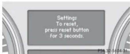
text_image
Settings To reset, press reset button for 3 seconds.▶ Press the reset button in the instrument cluster for approximately 3 seconds. The request to press the reset button once more to confirm appears in the multifunction display.
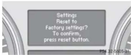
text_image
Settings Reset to Factory settings? To confirm, press reset button.▶ Press the reset button once more. The functions of all the submenus will be reset to factory settings.
The settings you have changed will not be reset unless you confirm the action by pressing the reset button a second time. After approximately 5 seconds, the Settings menu reappears in the multifunction display.
Controls in detail
Control system
Submenus in the Settings menu
▶ Press button 📄 or 📋 repeatedly until the Settings menu appears in the multifunction display.
▶ Press button ▲.
The collection of the submenus appears in the multifunction display. There are more submenus than can be simultaneously displayed.
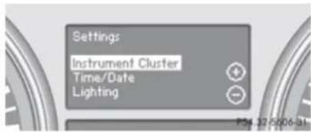
text_image
Settings Instrument Cluster Time/Date Lighting▶ Press button —.
The selection marker moves to the next submenu.
▶ Scroll down with button —, scroll up with button +.
With the selection marker on the desired submenu, use button 📁 to access the individual functions within that submenu.
▶ Once within the submenu, use button to move to the next function or button
to move to the previous function within that submenu.
▶ Use button + or - to change the settings of the respective function.
The following lists show what settings can be changed within the various menus. Detailed instructions on making individual settings can be found on the following pages.
Instrument cluster submenu
- Selecting speedometer display mode (▷ page 159)
- Selecting language (▷ page 159)
- Selecting display (digital speedometer or outside temperature) for status indicator (▷ page 159)
Time/Date submenu
- Setting the time (▷ page 160)
- Setting the date (▷ page 160)
Lighting submenu
- Setting daytime running lamp mode (USA only) (▷ page 161)
-
Setting locator lighting (▷ page 161)
-
Setting night security illumination (Headlamps delayed shut-off feature) (▷ page 162)
- Setting interior lighting delayed shut-off (▷ page 162)
Vehicle submenu
- Setting automatic central locking (▷ page 163)
Comfort submenu
- Activating easy-entry/exit feature (▷ page 163)
- Setting fold-in function for exterior rear view mirrors (> page 164)
Instrument cluster submenu
Access the Instrument Cluster submenu via the Settings menu. Use the Instrument Cluster submenu to change the instrument cluster display settings.
Controls in detail
Control system
The following functions are available:
- Selecting speedometer display mode (> page 159)
- Selecting language (▷ page 159)
- Selecting display (digital speedometer or outside temperature) for status indicator (> page 159)
Selecting speedometer display mode
▶ Move the selection marker with button
+ or - to the Instrument
Cluster submenu.
▶ Press button ▲ or ▼ repeatedly until the message Display Unit Digital Speedometer appears in the multifunction display.
The selection marker is on the current setting.
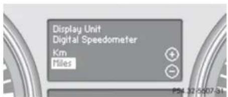
text_image
Display Unit Digital Speedometer Km Miles▶ Press button + or — to set speedometer unit to Km or Miles.
Selecting language
▶ Move the selection marker with button + or — to the Instrument Cluster submenu.
▶ Press button 🏠 or 🚡 repeatedly until the message Language appears in the multifunction display.
The selection marker is on the current setting.
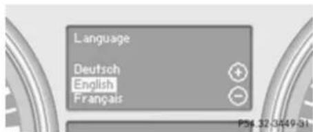
text_image
Language Deutsch English Français▶ Press button + or - to select the language to be used for the multifunction display messages.
Selecting display (digital speedometer or outside temperature) for status indicator
▶ Move the selection marker with button + or — to the Instrument Cluster submenu.
▶ Press button 🏠 or 🖼 repeatedly until the message Status Line Display appears in the multifunction display. The selection marker is on the current setting.
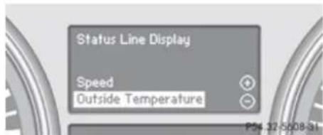
text_image
Status Line Display Speed Outside Temperature▶ Press button + or — to select the desired setting.
The selected display is then shown continuously in the status indicator (lower display).
The other display now appears in the Standard display menu (▷ page 152).
Controls in detail
Control system
Time/Date submenu
Access the Time/Date submenu via the Settings menu. Use the Time/Date submenu to change the time and date display settings.
The following functions are available:
- Setting the time ( > page 160)
- Setting the date (▷ page 160)
If your vehicle is equipped with the COMAND system and navigation module, see separate COMAND system operating instructions for information on how to set the time and date.
Setting the time
This function is not available if your vehicle is equipped with the COMAND system and navigation module.
▶ Move the selection marker with button + or - to the Time/Date submenu.
▶ Press button or repeatedly until the message Clock Set Hour or Clock Set Minute(s) appears in the multifunction display.
The selection marker is on the current setting.
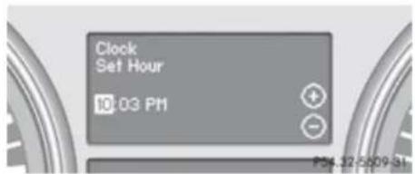
text_image
Clock Set Hour 10:03 PMExample illustration for setting the hour
▶ Press button + or — to set the hours or minute(s).
Setting the date
This function is not available if your vehicle is equipped with the COMAND system and navigation module.
▶ Move the selection marker with button + or - to the Time/Date submenu.
▶ Press button 🏠 or 🚡 repeatedly until the message Date Set Month, Date Set Day, or Date Set Year appears in the multifunction display.
The selection marker is on the current setting.
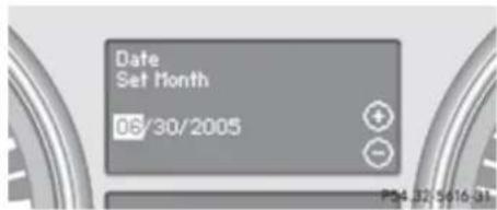
text_image
Date Set Month 06/30/2005Example illustration for setting the month
▶ Press button + or - to set the month, day, or year.
Lighting submenu
Access the Lighting submenu via the Settings menu. Use the Lighting submenu to change the lamp and lighting settings on your vehicle.
The following functions are available:
- Setting daytime running lamp mode (USA only) (> page 161)
- Setting locator lighting (▷ page 161)
- Setting night security illumination (▷ page 162)
- Setting interior lighting delayed shut-off (▷ page 162)
Controls in detail
Control system
Setting daytime running lamp mode (USA only)
▶ Move the selection marker with button + or — to the Lighting submenu.
▶ Press button 🏠 or 🚪 repeatedly until the message Lamp Circuit Headlamp appears in the multifunction display. The selection marker is on the current setting.
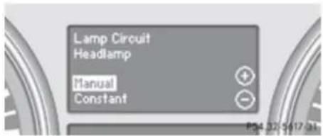
text_image
Lamp Circuit Headlamp Manual Constant▶ Press button + or — to select manual operation (Manual) or daytime running lamp mode (Constant).
With daytime running lamp mode activated and the exterior lamp switch in position 0 or AUTO, the low-beam headlamps are switched on when the engine is running.
In low ambient light conditions the following lamps will come on additionally:
- Parking lamps
- Tail lamps
- License plate lamps
- Side marker lamps
For more information on the daytime running lamp mode, see "Lighting" (▷ page 116).
For safety reasons, changing the setting for the daytime running lamp mode is not possible while the vehicle is in motion.
The following message appears in the multifunction display:
Settings can only be made at a standstill.
For safety reasons, resetting all the functions of all submenus to the factory settings while driving (▷ page 157) will not deactivate the daytime running lamp mode.
Setting locator lighting
With the locator lighting feature activated, the exterior lamp switch in position AUTO and the interior lighting in automatic mode (> page 120), the following lamps will come on during darkness when the vehicle is
unlocked using button 📊 on the SmartKey:
- Parking lamps
- Tail lamps
- License plate lamps
- Side marker lamps
- Front fog lamps
The locator lighting goes out when the driver's door is opened.
If you do not open the driver's door after unlocking the vehicle with the SmartKey, the lamps will go out automatically after approximately 40 seconds.
▶ Move the selection marker with button + or - to the Lighting submenu.
▶ Press button 🏠 or 🚡 repeatedly until the message Surround Lighting Function appears in the multifunction display.
The selection marker is on the current setting.
Controls in detail
Control system
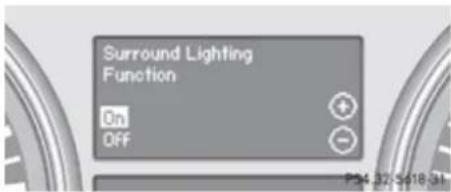
text_image
Surround Lighting Function On Off▶ Press button + or - to switch the locator lighting function On or Off.
▶ Turn the exterior lamp switch to position AUTO when exiting the vehicle.
The locator lighting feature is activated.
Setting night security illumination (Headlamps delayed shut-off feature)
Use this function to set whether you would like the exterior lamps to remain on for 15 seconds during darkness after exiting the vehicle and closing all doors.
With the headlamps delayed shut-off feature activated and the exterior lamp switch in position AUTO before the engine is turned off, the following lamps will come on when the engine is turned off:
- Parking lamps
- Tail lamps
-
License plate lamps
-
Side marker lamps
- Front fog lamps
If, after turning off the engine, you do not open a door or do not close an opened door, the lamps will automatically go out after 60 seconds.
▶ Move the selection marker with button + or - to the Lighting submenu.
▶ Press button 🏠 or 🚪 repeatedly until the message Headlamp Delayed Shut-off appears in the multifunction display. The selection marker is on the current setting.
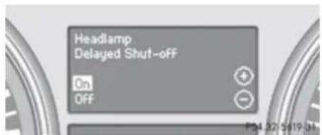
text_image
Headlamp Delayed Shut-off On Off▶ Press button + or — to switch the headlamps delayed shut-off feature On or Off.
▶ Turn the exterior lamp switch to position AUTO before turning off the engine.
The headlamps delayed shut-off feature is activated.
You can temporarily deactivate the headlamps delayed shut-off feature:
Before exiting the vehicle, turn the SmartKey in the starter switch to position 0.
▶ Then turn it to position 2 and back to position 0.
The headlamps delayed shut-off feature is deactivated. It will reactivate as soon as you start the engine.
Setting interior lighting delayed shut-off
Use this function to set whether you would like the interior lighting to remain on for 10 seconds during darkness after you have removed the SmartKey from the starter switch.
Controls in detail
Control system
▶ Move the selection marker with button + or - to the Lighting submenu.
▶ Press button △ or ▼ repeatedly until the message Interior Lighting Delayed Shut-off appears in the multifunction display.
The selection marker is on the current setting.
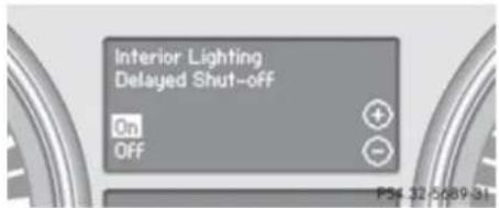
text_image
Interior Lighting Delayed Shut-off On Off P34 12-0089-31▶ Press button + or - to switch the interior lighting delayed shut-off feature On or Off.
Vehicle submenu
Access the Vehicle submenu via the Settings menu. Use the Vehicle submenu to set the automatic locking.
Setting automatic central locking
Use this function to activate or deactivate the automatic central locking. With the automatic central locking system activated, the vehicle is centrally locked at a vehicle speed of approximately 9 mph (15 km/h).
▶ Move the selection marker with button + or — to the Vehicle submenu.
▶ Press button 📁 or 🏠 repeatedly until the message Automatic Door Locking appears in the multifunction display. The selection marker is on the current setting.
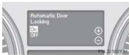
text_image
Automatic Door Locking On Off▶ Press button + or — to switch the automatic central locking On or Off.
Comfort submenu
Access the Comfort submenu via the Settings menu. Use the Comfort submenu to activate the easy-entry/exit feature
(▷ page 163) or to set the fold-in function for exterior rear view mirrors (▷ page 164).
Activating easy-entry/exit feature
Use this function to activate and deactivate the easy-entry/exit feature (▷ page 109).
Warning!
You must make sure no one can become trapped or injured by the moving steering wheel when the easy-entry/exit feature is activated.
To stop steering wheel movement do one of the following:
- Move steering wheel adjustment stalk.
- Press one of the memory position buttons.
- Press memory button M.
Do not leave children unattended in the vehicle, or with access to an unlocked vehicle. Children could open the driver's door and unintentionally activate the easy-entry/exit feature, which could result in an accident and/or serious personal injury.
Controls in detail
Control system
▶ Move the selection marker with button + or - to the Comfort submenu.
▶ Press button or repeatedly until the message Easy-entry Function appears in the multifunction display. The selection marker is on the current setting.
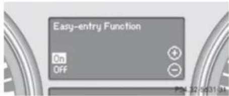
text_image
Easy-entry Function On OFF + - P= 32 -0.31 /4t▶ Press button + or — to switch the easy-entry feature On or Off.
Setting fold-in function for exterior rear view mirrors
Use this function to set the exterior rear view mirrors to be automatically folded in when you lock your vehicle.
With this function set to On and the exterior rear view mirrors folded in using the button on the door control panel (▷ page 112), the exterior rear view mirrors will not fold out when you switch on the ignition. You will then have to fold out the exterior rear view mirrors
using the button on the door control panel ( page 112).
Make sure both exterior rear view mirrors are folded out completely before driving off.
▶ Move the selection marker with button + or - to the Comfort submenu.
▶ Press button △ or ▽ repeatedly until the message Fold In Mirrors When Locking appears in the multifunction display.
The selection marker is on the current setting.
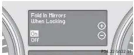
text_image
Fold In Mirrors When Locking On OFF▶ Press button + or — to switch function On or Off.
Vehicle configuration menu
Use the Vehicle configuration menu to activate/deactivate the Distance warning function (▷ page 164) or to set the DSR speed (▷ page 165).
Distance warning function
In vehicles equipped with Distronic, you can determine whether the distance warning function is to be enabled or disabled. With this function set to On, the system will alert you when recognizing a stationary obstacle or a slower vehicle moving in your vehicle's path and the danger of a collision exists, even when the Distronic is switched off.
▶ Press button 📄 or 📋 repeatedly until the vehicle configuration menu appears in the multifunction display.
▶ Press button 🏠 or 🖼 repeatedly until the message Distance Warning appears in the multifunction display.
The selection marker is on the current setting.
Controls in detail
Control system
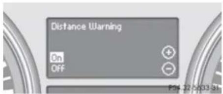
text_image
Distance Warning On Off▶ Press button + or - to switch the distance warning function On or Off.
① Symbol for activated distance warning function
If the distance warning function is activated you will see the symbol 📄 in the Standard display. When the distance warning function is deactivated the symbol 📄 will not appear.
DSR (Downhill Speed Regulation) programmed default speed
Use this function to program the default speed the DSR is set to when it is activated. You can program the default speed between 4 - 10 mph (Canada: 6 - 18 km/h). The set value is increased in 1 mph (Canada: 2 km/h) increments.
▶ Press button 📋 or 📋 repeatedly until the Vehicle configuration menu appears in the multifunction display.
▶ Press button or repeatedly until the message DSR Speed appears in the multifunction display.
The selection marker is on the current setting.
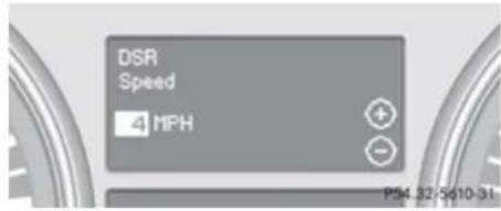
text_image
DSR Speed 4 MPH P54.32-9610-31Press button + or - repeatedly until the desired speed is shown in the multifunction display. When DSR is switched on, DSR will use the programmed default speed to regulate the vehicle's speed.
Once DSR is switched on, you can adjust the set speed using the cruise control lever ( page 183).
Trip computer menu
Use the Trip computer menu to call up statistical data on your vehicle.
The following information is available:
- Fuel consumption statistics since start ( page 165)
- Fuel consumption statistics since last reset ( page 166)
- Resetting fuel consumption statistics ( page 166)
• Distance to empty (▷ page 166)
When you enter the Trip computer menu, you will always see the fuel consumption statistics since start first.
Fuel consumption statistics since start
▶ Press button 📄 or 📄 repeatedly until the message From Start appears in the multifunction display.
Controls in detail
Control system
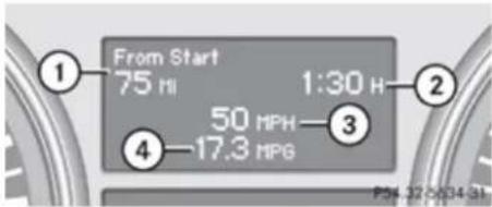
text_image
From Start 75 H 1:30 H 50 MPH -3 4 -17.3 MPG P#: 12-0034 3h① Distance driven since start
② Time elapsed since start
③ Average speed since start
④ Average fuel consumption since start
All statistics stored since the last engine start will be reset approximately 4 hours after the SmartKey in the starter switch is turned to position 0 or removed from the starter switch. Resetting will not occur if you turn the SmartKey back to position 1 or 2 within this time period.
Fuel consumption statistics since last reset
▶ Press button or repeatedly until the message From Start appears in the multifunction display.
▶ Press button 🏠 or 🖼 repeatedly until the message From Reset appears in the multifunction display.
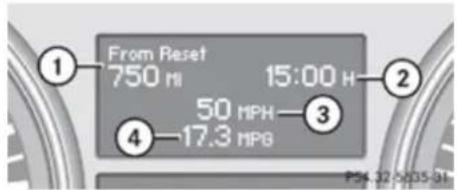
text_image
From Reset 750 mH 15:00 H 50 MPH—3 4—17.3 MPa PSX 12 PSX 31① Distance driven since last reset
② Time elapsed since last reset
③ Average speed since last reset
④ Average fuel consumption since last reset
Resetting fuel consumption statistics
▶ Press button or repeatedly until the message From Start appears in the multifunction display.
▶ Press button or repeatedly until the reading that you want to reset appears in the multifunction display.
▶ Press and hold the reset button in the instrument cluster until the respective values are reset to 0.
The fuel consumption statistics reset automatically to 0 after 99 999 miles or 9 999 hours, whichever occurs first.
Distance to empty
▶ Press button 📄 or 📋 repeatedly until the message From Start appears in the multifunction display.
▶ Press button or repeatedly until the message Range: appears in the multifunction display.
The calculated remaining driving range based on the current fuel tank level appears in the multifunction display.
If only very little fuel is left in the tank, a vehicle at the fuel pump 📄 appears instead of the remaining driving range.
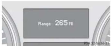
text_image
Range: 265 Hl P:4 32 0036-31Controls in detail
Control system
Telephone menu

Warning!
A driver's attention to the road must always be his/her primary focus when driving. For your safety and the safety of others, we recommend that you pull over to a safe location and stop before placing or taking a telephone call. If you choose to use the telephone while driving, please use the hands-free device and only use the telephone when weather, road and traffic conditions permit.
Some jurisdictions prohibit the driver from using a mobile phone while driving a vehicle.
Bear in mind that at a speed of just 30 mph (approximately 50 km/h), your vehicle is covering a distance of 44 feet (approximately 14 m) every second.
Never operate radio transmitters equipped with a built-in or attached antenna (i.e. without being connected to an external antenna) from inside the vehicle while the engine is running. Doing so could lead to a malfunction of the vehicle's electronic system, possibly resulting in an accident and/or personal injury.
You can connect your telephone to the COMAND system via Bluetooth ^® , see separate COMAND system operating instructions.
▶ Switch on the COMAND system.
Refer to separate COMAND system operating instructions.
▶ Press button or repeatedly until the message TEL appears in the multifunction display.
One of the following messages will appear in the multifunction display:
• No Service: No network is available.
- Bluetooth Ready: The telephone has not been connected to the COMAND system via Bluetooth® yet.
Connect the telephone to the COMAND system via Bluetooth®.
- Ready or name of the network provider (if available): The telephone has found a network and is ready for use. You can operate it using the control system.
Answering a call
When your telephone is ready to receive calls, you can answer a call at any time. In the
multifunction display you will then see the following message, or if available, the caller ID (number or name):
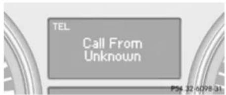
text_image
TEL Call From Unknown P54 32 6098 31▶ Press button 📞.
You have answered the call.
Ending a call or rejecting an incoming call
▶ Press button
Dialing a number from the phone book
When your telephone is ready to receive calls, you may select and dial a number from the phone book at any time.
▶▶
Controls in detail
Control system
▶ Press button 📄 or 📄 repeatedly until the message TEL appears in the multifunction display.
▶ Press button or repeatedly until the desired name appears in the multifunction display.
If you press and hold button or for longer than 1 second, the system scrolls rapidly through the list of names until you release the button again. The stored names are displayed in ascending or descending alphabetical order.
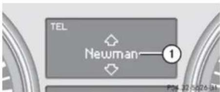
text_image
TEL Newman—1 P36.32-0p26-Jh① Selected name from the phone book
▶ Press button 📄. The control system dials the selected phone number. If the connection is successful and this feature is supported by your network provider, the name of the party (if stored in
your phone book) you are calling will appear in the multifunction display. The control system stores the dialed number in the redial memory.
or
▶ Press button 📞 if you do not want to make the call.
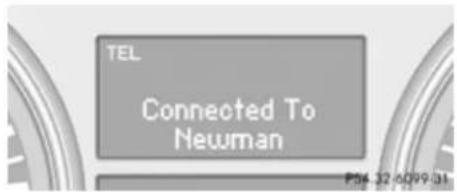
text_image
TEL Connected To Newman P54 32 0099 31Redialing
The control system stores the most recently dialed phone numbers. This eliminates the need to search through your entire phone book.
▶ Press button 📄 or 📄 repeatedly until the message TEL appears in the multifunction display.
▶ Press button 📞.
The first number in the redial memory appears in the multifunction display.
▶ Press button △ or ▼ repeatedly until the desired number or name appears in the multifunction display.
▶ Press button 📞.
The control system dials the selected phone number.
Driving systems
Driving systems
Introduction
This section describes the following driving systems of your vehicle:
• Cruise control and Distronic
- Distance warning function is only available with Distronic
- Hill start assist system
• Downhill Speed Regulation (DSR)
- Off-road driving program (vehicles without enhanced off-road package)
• Air suspension program (Adaptive Damping System (ADS) and vehicle level control)
- Parktronic system
- Rear view camera
Vehicles with enhanced off-road package: For information on LOW RANGE mode, see "LOW RANGE mode" ( page 142) and for information on differential locks, see "Differential locks" ( page 144).
The ABS, BAS, EBP, ESP ^® and 4-ETS driving safety systems are described in the “Safety and security” section ( > page 75).
Cruise control
The cruise control automatically maintains the speed you set for your vehicle.
The use of the cruise control is recommended for driving at a constant speed for extended periods of time.
The currently set speed or last set speed ("Resume" function) appears in the status indicator of the multifunction display:
• USA only: e.g. Cruise 55 Miles
• Canada only: e.g. 90 Km/h
The cruise control should not be activated during off-road driving.
Warning!
The cruise control is a convenience system designed to assist the driver during vehicle operation. The driver is and must always remain responsible for the vehicle's speed and for safe brake operation.
Only use the cruise control if the road, traffic, and weather conditions make it advisable to travel at a constant speed.
• The use of the cruise control can be dangerous on winding roads or in heavy
traffic because conditions do not allow safe driving at a constant speed.
- The use of the cruise control can be dangerous on slippery roads. Rapid changes in tire traction can result in wheel spin and loss of control.
- Deactivate the cruise control when driving in fog.
The “Resume” function should only be operated if the driver is fully aware of the previously set speed and wishes to resume this particular preset speed.
Warning!
The cruise control brakes automatically so that the set speed is not exceeded. The brake pedal depresses automatically when the cruise control engages the brakes.
Keep the driver's footwell clear at all times, including the area under the brake pedal. Objects stored in this area may impair pedal movement which could interfere with the braking ability of the cruise control system.
Do not place your foot under the brake pedal – your foot could become caught.
Controls in detail
Driving systems
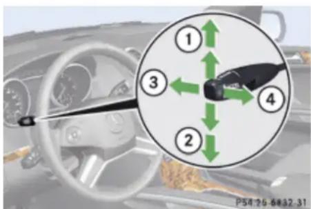
text_image
① ③ ② ④ P54 76 6832.31① Setting current or higher speed
② Setting current or lower speed
③ Canceling the cruise control
④ Activating the cruise control or resuming to last set speed
Activating cruise control
You can activate the cruise control at a vehicle speed above 20 mph (30 km/h).
You cannot activate the cruise control:
- when you brake
-
when you have engaged the parking brake
-
when the automatic transmission is in park position P, reverse gear R, or neutral position N
- the ESP ^ is switched off or has switched off due to a malfunction
The vehicle speed displayed in the speedometer can briefly vary from the speed setting for the cruise control system.
Setting current speed
▶ Accelerate or decelerate to the desired speed.
▶ Briefly lift the cruise control lever in direction of arrow ① or press in direction of arrow ②.
▶ Remove your foot from the accelerator pedal.
On uphill grades, the cruise control may not be able to maintain the set speed. Once the grade eases, the set speed will be resumed.
On downhill grades, the cruise control maintains the set speed by braking with the vehicle's brake system. In addition, on longer downhill grades the automatic transmission will downshift automatically.
Canceling cruise control
▶ Depress the brake pedal.
or
▶ Briefly push the cruise control lever in direction of arrow ③.
The last set speed is stored for later use.
The last stored speed is deleted from memory when the engine is turned off.
The cruise control switches off automatically when you depress the brake pedal or you engage the parking brake.
The cruise control switches off automatically and an acoustic warning will sound when
- the vehicle speed falls below 20 mph (30 km/h)
- the ESP ^ is in operation
- the ESP ^ is switched off with the ESP ^ switch
- the ESP ^ has switched off due to a malfunction
- you shift the automatic transmission into neutral position N while driving
Observe additional messages in the multifunction display that may appear.
Controls in detail
Driving systems
Depressing the accelerator pedal does not deactivate the cruise control. After a brief acceleration (e.g. for passing), the cruise control will resume the last set speed.
Changing the set speed

Warning!
Keep in mind that it may take a brief moment until the vehicle has made the necessary adjustments.
Increase or decrease the set vehicle speed to a value that the prevailing road conditions and legal speed limits permit. Otherwise, sudden and unexpected acceleration or deceleration of the vehicle could cause an accident and/or serious injury to you and others.
You can increase or decrease the set speed in 1 mph (Canada: 1 km/h) increments or in 5 mph (Canada: 10 km/h) increments.
When you use the cruise control lever to decelerate, the brake system will brake the vehicle automatically if the engine's braking power does not brake the vehicle sufficiently.
Adjustment in 1 mph (Canada: 1 km/h) increments
The set speed value is increased or decreased in 1 mph (Canada: 1 km/h) increments each time you lift or press the cruise control lever up or down to the resistance point.
▶ Briefly lift the cruise control lever up to the resistance point in direction of arrow ① to increase or press the cruise control lever down to the resistance point in direction of arrow ② to decrease.
▶ Release the cruise control lever.
The new speed is set and the vehicle will accelerate or decelerate.
Adjustment in 5 mph (Canada: 10 km/h) increments
The set speed value is increased or decreased in 5 mph (Canada: 10 km/h) increments each time you lift or press the cruise control lever up or down past the resistance point.
▶ Briefly lift the cruise control lever up past the resistance point in direction of arrow ① to increase or press the cruise control
lever down past the resistance point in direction of arrow ② to decrease.
▶ Release the cruise control lever.
The new speed is set and the vehicle will accelerate or decelerate. Keep in mind that it may take a brief moment until the vehicle has reached the set speed.
Resume last stored speed

Warning!
The set speed stored in memory should only be set again if prevailing road conditions and legal speed limits permit. Possible acceleration or deceleration differences arising from returning to the preset speed could cause an accident and/or serious injury to you and others.
▶ Briefly pull the cruise control lever in direction of arrow ④.
If no speed is stored, the current speed is set and stored.
▶ Remove your foot from the accelerator pedal.
The last stored speed is deleted from memory when the engine is turned off.
Controls in detail
Driving systems
Distronic
Safety notes
When activated, the Distronic adaptive cruise control increases the driving convenience afforded by the cruise control while traveling on expressways and other major roadways.
- If the Distronic distance sensor detects a slower moving vehicle directly ahead, your vehicle speed will be reduced so that you follow that vehicle at your preset following distance.
- If there is no vehicle directly ahead of you, the Distronic will function in the same way as standard cruise control ( page 169).
Warning!
The Distronic is a convenience system. Its speed adjustment reduction capability is intended to make cruise control more effective and usable when traffic speeds vary. It is not however, intended to, nor does it, replace the need for extreme care. The responsibility for the vehicle's speed, distance to the preceding vehicle and, most importantly, brake operation to ensure a safe stopping distance, always remains with the driver.
Complex driving situations are not always fully recognized by the Distronic. This could result in wrong or missing distance warnings.
Warning!
The Distronic adaptive cruise control is not a substitute for active driving involvement. It does not react to pedestrians or on stationary objects, nor does it recognize or predict the lane curvature or the movement of preceding vehicles.
The Distronic can only apply 20% of the maximum braking power of the vehicle. It is the driver's responsibility at all times to be attentive to the road, weather and traffic conditions. Additionally, the driver must provide the steering, braking and other driving inputs necessary to remain in control of the vehicle.
High-frequency sources such as toll stations, speed measuring systems etc. can cause the Distronic system to malfunction.
Warning!
The Distronic requires familiarity with its operational characteristics. We strongly
recommend that you review the following information carefully before operating the system.
Warning!
The Distronic cannot take road and traffic conditions into account. Only use the Distronic if the road, weather and traffic conditions make it advisable to travel at a constant speed.
Warning!
Use of the Distronic can be dangerous on slippery roads. Rapid changes in tire traction can result in wheel spin and loss of control.
The Distronic does not function in adverse sight and distance conditions. Do not use the Distronic during conditions of fog, heavy rain, snow or sleet.
Warning!
The Distronic cannot take weather conditions into account. Switch off the Distronic or do not switch it on if:
- roads are slippery or covered with snow or ice. The wheels could lose traction
Controls in detail
Driving systems
while braking or accelerating, and the vehicle could skid.
- the Distronic system sensor cover is dirty or visibility is diminished due to snow, rain or fog, for example. The distance control system functionality could be impaired.
Always pay attention to surrounding traffic conditions even while the Distronic is switched on. Otherwise, you may not be able to recognize dangerous situations until it is too late. This could cause an accident in which you and/or others could be injured.

Warning!
The “Resume” function should only be operated if the driver is fully aware of the previously set speed and wishes to resume this particular preset speed.

Warning!
Close attention to road and traffic conditions is imperative at all times, regardless of whether or not the Distronic is activated.
Use of the Distronic can be dangerous on winding roads or in heavy traffic because
conditions do not allow safe driving at a constant speed.
The Distronic will not react to stationary objects in the roadway (e.g. a stopped vehicle in a traffic jam or a disabled vehicle). The Distronic will also not respond to oncoming vehicles.
Switch off the Distronic:
- when changing from the left to the right lane if vehicles are moving more slowly in the left lane
- when entering a turn lane or highway off ramp
- in complex driving situations, such as in highway construction zones
In these situations, the Distronic will continue to maintain the set speed unless deactivated.
The Distronic is designed and intended only to maintain a set speed and keep a set distance from moving objects in front of it.
i USA only:
This device has been approved by the FCC as a “Vehicular Radar System”. The radar sensor is intended for use in an automotive radar system only. Removal, tampering, or
altering of the device will void any warranties, and is not permitted by the FCC. Do not tamper with, alter, or use in any non-approved way.
Any unauthorized modification to this device could void the user's authority to operate the equipment.
Canada only:
This device complies with RSS-210 of Industry Canada. Operation is subject to the following two conditions:
- This device may not cause interference, and
- this device must accept any interference received, including interference that may cause undesired operation of the device.
Removal, tampering, or altering of the device will void any warranties, and is not permitted. Do not tamper with, alter, or use in any non-approved way.
Any unauthorized modification to this device could void the user's authority to operate the equipment.
Controls in detail
Driving systems
Distronic displays in the speedometer
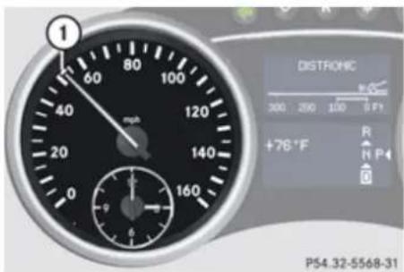
text_image
1 60 80 100 40 mph 120 20 140 0 160 DISTRICTIC 300 200 100 5 P+ +78°F R N P 4 P54.32-5568-31① Set speed
If the Distronic is activated, one or two cruise control speed segments come on around the set speed.
The vehicle speed displayed on the speedometer can briefly vary from the speed setting on the Distronic system.
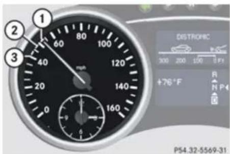
text_image
1 2 3 60 80 100 40 120 20 140 0 160 DISTROFIC 300 200 100 9 F1 +78°F R N P 4 P54.32-5569-31① Set speed
② Cruise control speed segments
③ Speed of the vehicle ahead
If the Distronic detects a vehicle directly ahead, the cruise control speed segments
② appear in the speedometer. These segments represent the difference between the set speed of your vehicle ① and the speed of the preceding vehicle ③.
If the Distronic calculates that there is a danger of collision, the distance warning lamp in the instrument cluster comes on and an intermittent warning sounds.
▶ Immediately apply the brakes to avoid a collision.
Under no circumstances should the driver await the intermittent warning sound before braking.
The intermittent warning sound ceases and the distance warning lamp △ goes out when the necessary distance to the vehicle ahead is established again.

Warning!
An intermittent warning sounds and the distance warning lamp ⚠️ in the instrument cluster is illuminated if the Distronic system calculates that the distance to the vehicle ahead and your vehicle’s current speed indicate that the Distronic will not be capable of slowing the vehicle sufficiently to maintain the preset following distance, which creates a danger of a collision.
Immediately brake the vehicle to increase your distance to the preceding vehicle. The warning sound is intended as a final caution in which you should intercede with your own braking inputs to avoid a potentially dangerous situation. Do not wait for the operation of the warning signal to intercede with your own braking. This will result in potentially dangerous emergency braking which will not always result in an impact being avoided.
Tailgating increases the risk of an accident.
Controls in detail
Driving systems

Warning!
The Distronic brakes your vehicle with a maximum deceleration of 6.5 ft/s^2 ( 2 m/s^2 ). This corresponds to approximately 20% of the maximum deceleration of your vehicle.
The Distronic brakes the vehicle in an effort to restore the preset distance or to maintain the set speed.
Keep driver's foot area clear at all times, including the area under the brake pedal. Objects stored in this area may impair pedal movement which could interfere with the braking ability of the Distronic system. Do not place your foot under the brake pedal - your foot could become caught.
Distronic menu in the control system
Use the DISTRONIC menu to display the current settings for your Distronic system. The information shown in the multifunction display depends on whether the Distronic system and/or the distance warning function are activated or deactivated.
To activate or deactivate the Distronic system, see (▷ page 176) or see (▷ page 178).
To activate or deactivate the Distance warning function, see (▷ page 164).
▶ Press button or repeatedly until one of the following two displays appears in the multifunction display.
Distronic deactivated
When the Distronic is deactivated, you will see the standard Distronic display in the multifunction display.
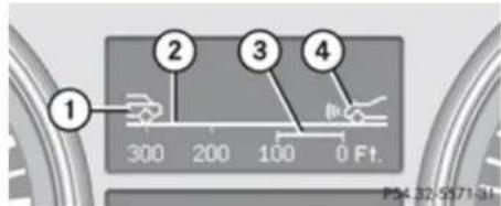
text_image
1 2 3 4 300 200 100 0 Ft. PS4.32.SS7131① Preceding vehicle, if detected
② Actual distance to the preceding vehicle
③ Preset distance threshold to the preceding vehicle
④ Your vehicle
Distronic activated
When the Distronic is activated, you will see the set speed in the multifunction display for
approximately 5 seconds. The following display appears in the multifunction display.
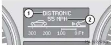
text_image
①—DISTRONIC 55 MPH 300 200 100 0 Ft PS4-32-8870-31① Distronic activated
② Set vehicle speed
After approximately 5 seconds the currently set speed appears in the status indicator of the multifunction display:
Cruise control lever
The Distronic system is operated by means of the cruise control lever.
Controls in detail
Driving systems
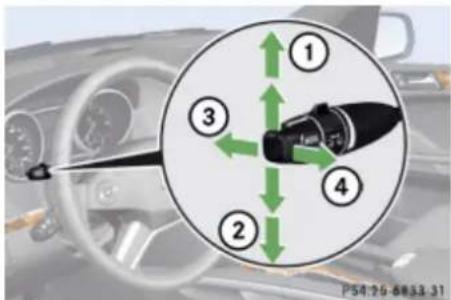
text_image
① ② ③ ④ P54 26 8833.31① Setting current or higher speed
② Setting current or lower speed
③ Deactivating the Distronic
④ Activating the Distronic or resuming to the last set speed
Activating Distronic
You can activate the Distronic when the vehicle speed is between 20 mph (30 km/h) and 110 mph (180 km/h).
When the Distronic is activated, one or two cruise control speed segments around the set speed in the speedometer dial are illuminated. The multifunction display will show a message such as
DISTRONIC 55 MPH
(Canada: DISTRONIC 90 km/h).
After approximately 5 seconds the currently set speed appears in the status indicator of the multifunction display:
• USA only: e.g. DTR 55 Miles
• Canada only: e.g. DTR 90 km/h
If the Distronic is not activated after the cruise control lever is pulled in direction of arrow ④ (▷ page 175), you will see the message DISTRONIC Off in the multifunction display.
In the following cases you cannot activate the Distronic:
• up to 2 minutes after starting the engine
- when you brake
- when you have engaged the parking brake
- when the automatic transmission is in park position P, reverse gear R, or neutral position N
- when the ESP ^ is switched off or has switched off due to a malfunction
The vehicle speed displayed on the speedometer can briefly vary from the speed setting on the Distronic system.
Setting the current speed
▶ Accelerate or decelerate to the desired speed.
▶ Briefly lift the cruise control lever in direction of arrow ① or depress in direction of arrow ② (▷ page 176).
Remove your foot from the accelerator pedal.
If you do not take your foot off of the accelerator pedal and continue to accelerate past the set speed, the following message will appear in the multifunction display:
DISTRONIC Override
The distance to a slower moving vehicle in front of you will not be set. Your vehicle speed will then be determined only by the accelerator pedal position.
Setting a higher speed
Warning!
Keep in mind that it may take a brief moment until the vehicle has made the necessary adjustments.
Controls in detail
Driving systems
Increase the set vehicle speed to a value that the prevailing road conditions and legal speed limits permit. Otherwise, sudden and unexpected acceleration of the vehicle could cause an accident and/or serious injury to you and others.
You can increase the set speed in 1 mph (Canada: 1 km/h) increments or in 5 mph (Canada: 10 km/h) increments.
Adjustment in 1 mph (Canada: 1 km/h) increments
The set speed value is increased in 1 mph (Canada: 1 km/h) increments each time you lift the cruise control lever up to the resistance point.
▶ Briefly lift the cruise control lever up to the resistance point in direction of arrow ① (> page 175).
▶ Release the cruise control lever.
The new speed is set and the vehicle will accelerate.
Adjustment in 5 mph (Canada: 10 km/h) increments
The set speed value is increased in 5 mph (Canada: 10 km/h) increments each time
you lift the cruise control lever up past the resistance point.
▶ Briefly lift the cruise control lever up past the resistance point in direction of arrow ① (▶ page 175).
▶ Release the cruise control lever.
The new speed is set and the vehicle will accelerate. Keep in mind that it may take a brief moment until the vehicle has reached the set speed.
Setting a lower speed
Warning!
Keep in mind that it may take a brief moment until the vehicle has made the necessary adjustments.
Decrease the set vehicle speed to a value that the prevailing road conditions and legal speed limits permit. Otherwise, sudden and unexpected deceleration of the vehicle could cause an accident and/or serious injury to you and others.
When you use the cruise control lever to decelerate, the brake system will automatically brake the vehicle if the
engine's braking power does not brake the vehicle sufficiently.
You can reduce the set speed in 1 mph (Canada: 1 km/h) increments or in 5 mph (Canada: 10 km/h) increments.
Adjustment in 1 mph (Canada: 1 km/h) increments
The set speed value is decreased in 1 mph (Canada: 1 km/h) increments each time you press the cruise control lever down to the resistance point.
▶ Briefly press the cruise control lever down to the resistance point in direction of arrow ②.
▶ Release the cruise control lever.
The new speed is set and the vehicle will decelerate.
Adjustment in 5 mph (Canada: 10 km/h) increments
The set speed value is decreased in 5 mph (Canada: 10 km/h) increments each time you press the cruise control lever down past the resistance point.
Controls in detail
Driving systems
▶ Briefly press the cruise control lever down past the resistance point in direction of arrow ②.
▶ Release the cruise control lever.
The new speed is set and the vehicle will decelerate. Keep in mind that it may take a brief moment until the vehicle has reached the set speed.
Setting stored speed (Resume function)

Warning!
The set speed stored in memory should only be set again if prevailing road conditions and legal speed limits permit. Possible acceleration or deceleration differences arising from returning to the preset speed could cause an accident and/or serious injury to you and others.
▶ Briefly pull the cruise control lever in direction of arrow ④ (▶ page 176).
If no speed is stored, the current speed is set and stored.
▶ Remove your foot from the accelerator pedal.
Deactivating Distronic
▶ Depress the brake pedal.
or
▶ Briefly push the cruise control lever in direction of arrow ③ (▶ page 176). The cruise control speed segments in the speedometer dial will go out and the following message appears briefly in the multifunction display: DISTRONIC Off The last set speed is stored for later use.
The last stored speed is deleted from memory when the engine is turned off.
The Distronic switches off automatically when you depress the brake pedal or you engage the parking brake. In this case, the cruise control speed segments in the speedometer dial will go out.
The Distronic also switches off automatically when
• the vehicle speed falls below 20 mph (30 km/h)
- the ESP® is in operation
- the ESP ^ is switched off with the ESP ^ switch
- the ESP ^ has switched off due to a malfunction
- you shift the automatic transmission into neutral position N while driving
The cruise control speed segments in the speedometer dial goes out and an acoustic warning will sound. Observe additional messages in the multifunction display that may appear.

Warning!
Distronic switches off and releases the brakes when the vehicle decelerates below the minimum speed of 20 mph (30 km/h) by operation of the system. At that time the driver must apply the brakes in order to reduce vehicle speed further or bring it to a stop.
Depressing the accelerator pedal does not deactivate the Distronic. After a brief acceleration (e.g. for passing), the Distronic will resume the last set speed.
Setting the following distance in Distronic
You can set the specified following distance for Distronic by varying the time setting between 1.0 and 2.0 seconds. Using this time
Controls in detail
Driving systems
setting and the current speed of your vehicle, Distronic calculates and sets the required following distance to the preceding vehicle. The set distance will be shown in the multifunction display.

Warning!
It is up to the driver to exercise discretion to select the appropriate setting given road conditions, traffic, driver's preferred driving style and applicable laws and driving recommendations for safe following distance.
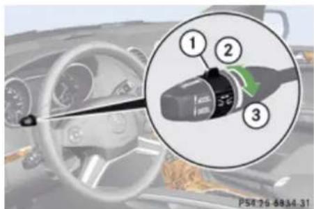
text_image
① ② ③ PS6 76-8034-31① Distance setting switch
② To decrease distance
③ To increase distance
▶ Increasing distance: Turn distance setting switch ① in direction of arrow ③. Increasing the distance setting tells Distronic to maintain a greater following distance to the preceding vehicle.
▶ Decreasing distance: Turn distance setting switch ① in direction of arrow ②. Decreasing the distance setting tells Distronic to maintain a shorter following distance to the preceding vehicle.
Driving with Distronic
This section describes a number of driving situations where special precaution is required on the part of the driver. Be prepared to brake in such situations. Braking will deactivate the Distronic system.

Warning!
Distronic works to maintain the speed selected by the driver unless a moving obstacle proceeding directly ahead of it in the same travel direction is detected (e.g. following another vehicle ahead of you at your set distance).
This means that:
- Your vehicle can pass another vehicle after you have changed lanes.
- While in a sharp turn or if the preceding vehicle is in a sharp turn, Distronic could lose sight of the preceding vehicle. Your vehicle could then accelerate to the previously selected speed.
Distronic regulates only the distance between your vehicle and those directly ahead of it, but does not register stationary objects in the road, e.g.:
• a stopped vehicle in a traffic jam
- a disabled vehicle
• an oncoming vehicle
The driver must always be alert, observe all traffic and intercede as required by means of steering or braking the vehicle.

Warning!
Distronic should not be used in snowy or icy road conditions.
The most likely cause for a malfunctioning system is a dirty Distronic system sensor cover (located in the hood grille), especially at times of snow and ice or heavy rain.
Controls in detail
Driving systems
In such a case, Distronic will switch off, and the message DISTRONIC Currently Unavailable - See Operator's Manual appears in the multifunction display.
For cleaning and care of the Distronic system sensor cover, see (▷ page 321).
i If the message DISTRONIC Available Again appears during driving, the dirt (e.g. slush) has dissolved; Distronic works again, if you reactivate it (▶ page 176).
Turns and bends
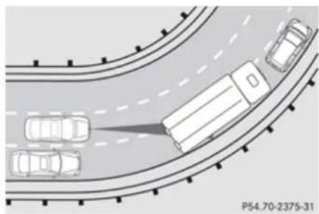
natural_image
Top-down diagram of a multi-lane highway intersection with vehicles, no text or symbols presentIn turns or bends, Distronic may not detect a moving vehicle in front, or it may detect one too soon. This may cause your vehicle to brake late or unexpectedly.
Offset driving
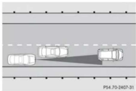
natural_image
Top-down view of three cars on a multi-lane road with a shadow line (no text or symbols)A vehicle traveling in your lane but offset from your direct line of travel may not be detected by Distronic. There will be insufficient distance to the preceding vehicle.
Lane changing
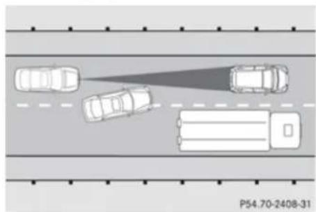
natural_image
Top-down diagram of a multi-lane road with vehicles and a truck, no text or symbols presentDistronic has not yet detected the vehicle changing lanes. There will be insufficient distance to the lane-changing vehicle.
Narrow vehicles
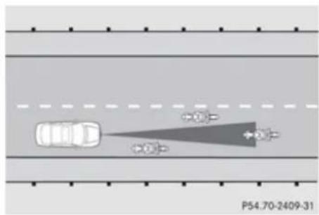
text_image
P54.70-2409-31Because of their narrow profile, the vehicles traveling near the outer edges of the lane have not yet been detected by Distronic. There will be insufficient distance to the preceding vehicles.
Controls in detail
Driving systems
Distance warning function
When the Distronic is deactivated, this function will continue to warn you when recognizing a stationary obstacle or a slower vehicle moving in your vehicle's path and the danger of a collision exists:
- The distance warning lamp ⚠️ in the instrument cluster comes on.
- An intermittent warning will sound if necessary.
If these warnings are issued, you must brake manually to maintain a safe distance and avoid a collision with the preceding vehicle.
When depressing the brake pedal, the warning sound ceases. The warning sound will also cease when the distance to the preceding vehicle is sufficient again without applying the brakes. In this case, the distance warning lamp ⚠️ will also go out.

Warning!
If the distance warning lamp ⚠ in the instrument cluster comes on while driving and/or an intermittent warning sounds, immediate attention on the part of the driver is required. As required by the traffic situation, apply the brakes and navigate around a possible obstacle. However, do
not drive by relying on the distance warning function, as this will result in an emergency braking application. This will not always enable you to avoid a collision, especially when traveling on varying road surface conditions and with varying driver reaction.
Complex driving situations are not always fully recognized by the distance warning function. This could result in wrong or missing distance warnings.
▶ Switch on the distance warning function in the control system (▷ page 164).
Hill start assist system
Warning!
The hill start assist system is not designed to function as a parking brake and does not prevent the vehicle from moving when parked on an incline.
Always engage the parking brake in addition to shifting the automatic transmission into park position P.
On uphill grades with a gradient angle of more than 5^ , the hill start assist system maintains the pressure in the brake system for approximately 1 second after you have
released the brake pedal. Therefore, you can start off smoothly without the vehicle moving immediately after releasing the brake pedal.
▶ Depress the brake pedal.
▶ Shift the automatic transmission into drive position D or reverse gear R.
▶ Release the brake pedal.
▶ Carefully depress the accelerator pedal.
The hill start assist system is inactive
- when starting off on a level road or downhill grades
• with the automatic transmission in neutral position N
• with the parking brake engaged - if the ESP ^ has switched off due to a malfunction
Controls in detail
Driving systems
Downhill Speed Regulation (DSR)
Warning!
The Downhill Speed Regulation (DSR) is a convenience system designed to assist the driver during vehicle operation. The system must be set to be appropriate for the topographical and weather conditions encountered which can change quickly. The driver is and must remain at all times responsible for the vehicle speed and for safe brake operation.
Depending on the programmed speed, actual vehicle speed and gradient, switching on the DSR while driving can cause the vehicle to slow down rapidly and you may hear a sound which is caused by the activation of the vehicle's brake system through the DSR. Sudden and unexpected deceleration can result in loss of vehicle control, causing an accident and/or serious personal injury to you and others. Do not switch on the DSR in a circumstance where rapid deceleration could result in a loss of vehicle control.
For more information, see "Off-road driving" (▷ page 303).
The DSR is an aid for driving downhill. The DSR regulates your vehicle's speed when driving downhill to the value set in the control system (▷ page 165). The steeper the downhill gradient is, the greater the brake application. On flat road surfaces, the DSR brakes only slightly or not at all.
The DSR regulates the vehicle's speed in automatic transmission positions D, or R.
In addition, make use of the engine's braking effect by shifting the automatic transmission into a lower gear.
You can drive slower or faster than the set speed at any time by braking the vehicle or depressing the accelerator pedal.
i Whenever the DSR is switched on, the DSR will use the programmed default speed to regulate the vehicle's speed. The default speed programmed at the factory is 4 mph (Canada: 6 km/h). The default speed can be reprogrammed using the control system ( page 165). The next time the DSR is switched on, the DSR will use the newly programmed default speed to regulate the vehicle's speed.
Once the DSR is switched on, you can adjust the set speed using the cruise control lever ( page 170). Keep in mind that adjusting the set speed using the cruise control lever with the DSR switched
on will not change the programmed default speed. If the DSR is switched off and then switched on again, the DSR will use the programmed default speed.
Depending on the road surface and level of downhill grade, the DSR may not be able to maintain the set speed. To maintain the set speed, apply the brakes if necessary.
Switching the DSR on/off
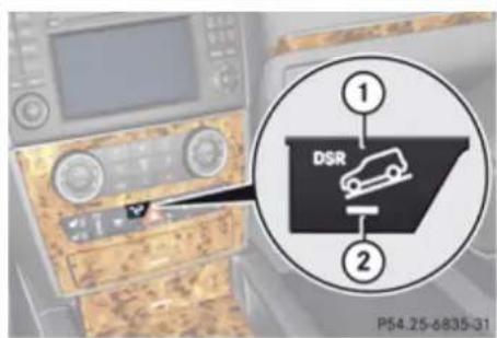
text_image
① DSR ② P54.25-6835-31Vehicles without enhanced off-road package
① DSR switch
② Indicator lamp
Controls in detail
Driving systems
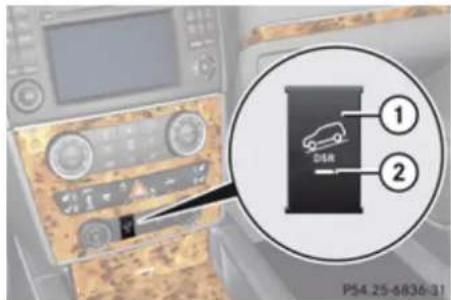
text_image
① ② P54.25-6836-31Vehicles with enhanced off-road package
① DSR switch
② Indicator lamp

Warning!
If the accelerator pedal is depressed while the Downhill Speed Regulation (DSR) is activated, the vehicle can drive faster than the programmed set speed. You should therefore drive downhill with particular caution as it could otherwise lead to an accident and/or serious injury to you or others. Keep in mind that as soon as you remove your foot from the accelerator pedal with the DSR switched on, the DSR will start regulating the vehicle's speed including use of brakes if required. Depending on the programmed set speed,
actual vehicle speed and gradient, the DSR can cause the vehicle to slow down rapidly. Sudden and unexpected deceleration can result in loss of vehicle control, causing an accident and/or serious personal injury to you and others.
Switching on the DSR
The DSR can only be switched on if the vehicle speed is below 18 mph (Canada: 30 km/h).
▶ Press DSR switch ①.
Indicator lamp ② comes on.
The message DSR and the set speed appear in the multifunction display.
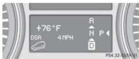
text_image
+76°F DSR 4 MPH R N P D P54.32-5550101If the DSR is switched on at a speed above 18 mph (Canada: 30 km/h), the message DSR Max. Speed 18 mph (Canada: 30 km/h) appears in the multifunction display.
For information on how to program the set speed while driving, see "Adjusting the DSR speed" (▷ page 183).
Switching off the DSR
▶ Press DSR switch ①.
The indicator lamp ② goes out.
The message DSR Off appears in the multifunction display.
At a speed above approximately 21 mph (Canada approximately: 35 km/h), the DSR is automatically switched off. The message DSR Off appears in the multifunction display and an acoustic signal sounds. For information on how to switch the DSR on again, see "Switching on the DSR" (▷ page 183).
Adjusting the DSR speed
With the DSR switched on (▷ page 183), the speed setting can be changed using the cruise control lever.
Controls in detail
Driving systems
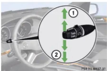
text_image
Diagram showing a car interior with labeled parts and directional arrows, likely illustrating vehicle or sensor placement.Cruise control lever
① Increase set speed
② Reduce set speed
You can change the set speed between 3-10 mph (Canada: 4-18 km/h).
You can increase or reduce the set speed in two ways.
Adjustment in 1 mph (Canada: 1 km/h) increments
The set value is increased or decreased in 1 mph (Canada: 1 km/h) increments each time you lift or depress the cruise control lever to the resistance point.
Increase set speed:
▶ Briefly lift the cruise control lever up to the resistance point in direction of arrow ①.
▶ Release the cruise control lever.
The vehicle speed increases in increments of 1 mph (Canada: 1 km/h).
Reduce set speed:
▶ Briefly press the cruise control lever down to the resistance point in direction of arrow ②.
▶ Release the cruise control lever.
The vehicle speed decreases in increments of 1 mph (Canada: 1 km/h).
Each time the set speed is changed, DSR will appear in the multifunction display and the changed set speed is shown.
The set speed is canceled when the DSR is switched off. If the DSR is switched on again, the DSR will use the programmed default speed ( page 165).
Adjustment in 5 mph (Canada: 10 km/h) increments
The set value is increased or decreased in 5 mph (Canada: 10 km/h) increments each
time you lift or depress the cruise control lever past the resistance point.
Increase set speed:
▶ Briefly lift the cruise control lever up past the resistance point in direction of arrow ①.
▶ Release the cruise control lever.
The vehicle speed increases in increments of 5 mph (Canada: 10 km/h).
Reduce set speed:
▶ Briefly press the cruise control lever down past the resistance point in direction of arrow ②.
▶ Release the cruise control lever.
The vehicle speed decreases in increments of 5 mph (Canada: 10 km/h).
Each time the set speed is changed, DSR will appear in the multifunction display and the changed set speed is shown.
The new speed is set and the vehicle will accelerate or decelerate. Keep in mind that it may take a brief moment until the vehicle has reached the new set speed.
The set speed is canceled when the DSR is switched off. If the DSR is switched on again,
Controls in detail
Driving systems
the DSR will use the programmed default speed (▷ page 165).
Off-road driving program (Vehicles without enhanced off-road package)
The off-road driving program is designed to assist the driver when driving off-road in terrain and crossing water. The off-road driving program adjusts the engine power and shifting of the automatic transmission to be more suitable for the off-road use of the vehicle. In addition, the ABS, ESP ^® , and 4-ETS designed for off-road use are automatically activated.
In the following situations you should switch to the off-road driving program:
• during off-road driving
- when crossing water ( page 306)
- when towing up or down on steep gradients
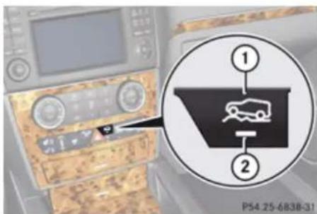
text_image
P54.25-6838-31① Switch for off-road driving program
② Indicator lamp
Switching off-road driving program on
▶ Press switch ①.
Indicator lamp ② comes on. The symbol appears in the lower multifunction display.
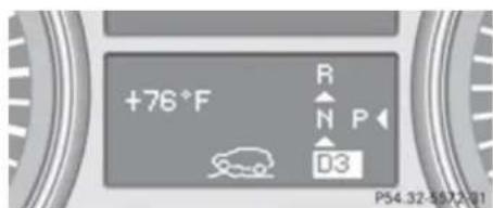
text_image
+76°F R N P D3 P54.32-557201Switching off-road driving program off
▶ Press switch ① again.
Indicator lamp ② goes out. The symbol disappears.
Air suspension program
The system consists of two components. The Adaptive Damping System (ADS)
(▷ page 185) and the vehicle level control
(▷ page 186).
Adaptive Damping System (ADS)
The fine tuning of the damping is dependent on:
- road surface conditions
- your driving style
- your personal ADS settings
- your personal vehicle level settings
Controls in detail
Driving systems
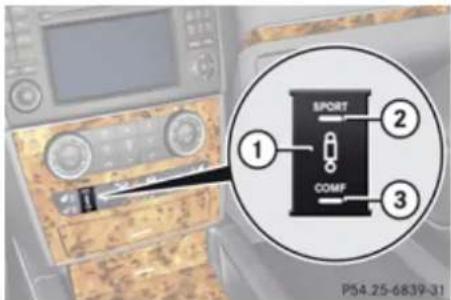
text_image
SPORT COMF ① ② ③ P54.25-6839-31Vehicles without enhanced off-road package
① ADS switch
② Indicator lamp for SPORT setting
③ Indicator lamp for COMF setting
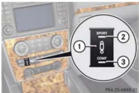
text_image
SPORT COMF ① ② ③ P54.25-6840-31Vehicles with enhanced off-road package
① ADS switch
② Indicator lamp for SPORT setting
③ Indicator lamp for COMF setting
The following settings are available:
- AUTO (for normal driving situations) Indicator lamps ② and ③ are off.
- SPORT (for sporty driving)
Indicator lamp ② comes on.
With the ADS SPORT setting, the vehicle is lowered approximately 0.6 in (15 mm).
• COMF (for comfort driving) Indicator lamp ③ comes on.
▶ Start the engine.
▶ Press ADS switch ① repeatedly until the desired suspension tuning is reached.
The setting remains stored when you turn off the engine.
Vehicle level control
Your vehicle automatically adjusts its ride height to increase vehicle safety and to reduce fuel consumption.
The vehicle automatically regulates its ride height based on the set vehicle height and the current speed:
- As your driving speed increases, the vehicle is lowered by increments until it reaches highspeed level.
- Vehicles with ADS: If you are driving with the ADS setting COMF or AUTO, the vehicle is raised back to highway level as your driving speed decreases.
- Vehicles with ADS: You can select the highspeed level via the ADS setting SPORT. In ADS SPORT, the vehicle is lowered directly to highspeed level as your driving speed increases.
The vehicle begins adjusting to the set vehicle level as soon as the doors or tailgate are unlocked or opened or closed with the vehicle unlocked.
In order to operate the vehicle level control switch (▷ page 187) or (▷ page 189), however, the engine must be running.
Controls in detail
Driving systems

Warning!
Make sure no one is near the wheel housing or under the vehicle when you lower the vehicle while it is standing still. Limbs could become wedged into or under the vehicle. For safety reasons, the vehicle can only be lowered with all doors and the tailgate closed. Lowering is interrupted if a door or the tailgate is opened and will continue after the door is closed again.

Warning!
Please be aware that by raising the vehicle level, the center of gravity also rises. Therefore, always ensure that the vehicle level is as low as possible. With higher ride height the ESP ^® may activate earlier in certain situations.
Adapt your speed and driving to possible changed driving behavior of the vehicle after changing the vehicle level. The ESP ^® cannot prevent accidents, including those resulting from excessive speed. The ESP ^® cannot prevent the natural laws of physics from acting on the vehicle.
! Keep in mind that in rough or uneven terrain, adjusting the vehicle to a lower
level may cause the vehicle underbody to come in contact with the ground and result in damage to the vehicle underbody. Always make sure the vehicle has sufficient ground clearance before adjusting it to a lower level.
! Before jacking up the vehicle with equipment that lifts one or more of the wheels completely off of the ground, remove the SmartKey from the starter switch.
For information on off-road driving, see "Off-road driving" (▷ page 303).
Vehicles without enhanced off-road package
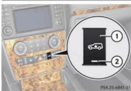
text_image
P54.25-6841-31① Vehicle level control switch
② Indicator lamp
Basic settings
The following vehicle chassis ride heights can be selected using the vehicle level control switch in the center console:
Level Driving situation
| Raised For off-road driving or driving in rough terrain. The indicator lamp is on. |
| Highway For driving on paved roads in fair or better condition. The indicator lamp is off. |
The third available level is the highspeed level that is set automatically.
The following is the approximate change in ride height for each of the level settings:
Level Ride height
| Raised +2.3 in (60 mm) |
| Highway9 | +/-0 in (0 mm) |
| Highspeed -0.6 in (-15 mm) |
Controls in detail
Driving systems
i Vehicles with ADS:
Depending on the ADS setting (▷ page 185), the vehicle will be lowered to the highspeed level when traveling at higher speeds. At speeds below 40 mph (64 km/h) at the latest, it will be returned to the highway level.
i The highspeed level is not available when towing a trailer. For more information on towing a trailer, see "Trailer towing" (▷ page 310).
Raised level
Only select the raised level if appropriate for the driving situation encountered. Otherwise the fuel consumption may increase and/or the handling characteristics of the vehicle may be unfavorable.
You can select the raised level at speeds up to 40 mph (64 km/h). At higher speeds, the message Level Selection Not Permitted appears in the multifunction display.
▶ Start the engine.
9 Ground clearance: 8.5 in (217 mm)
When indicator lamp ② is off:
▶ Press switch ①.
Indicator lamp ② flashes. The vehicle adjusts to the raised level.
The following message appears in the multifunction display while the level is being set:
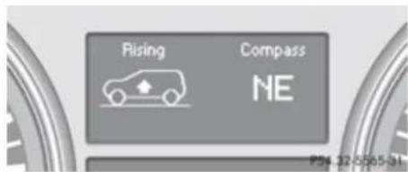
text_image
Rising Compass NE P56 32-05/05-24The message can be cleared by pressing the 📄, 📅, 🙏 or 🖼 button on the multifunction steering wheel.
When the raised level is reached, indicator lamp ② comes on continuously and the following message appears in the multifunction display for 5 seconds:
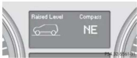
text_image
Raised Level Compass NE P24 32-0561/34Highway level
! Keep in mind that on rough or uneven roads, adjusting the vehicle to a lower level may cause the vehicle underbody to come in contact with the road and result in damage to the vehicle underbody. Always make sure the vehicle has sufficient ground clearance before adjusting it to a lower level.
▶ Start the engine.
When indicator lamp ② is on:
▶ Press switch ①.
Indicator lamp ② flashes. The vehicle adjusts to the highway level.
The following message appears in the multifunction display while the level is being set:
Driving systems
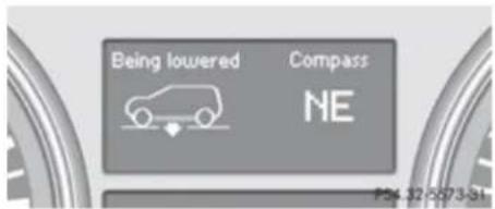
text_image
Being lowered Compass NE P4: 12-5073-SIThe message can be cleared by pressing the 📄, 📅, or ▼ button on the multifunction steering wheel.
When the highway level is reached, indicator lamp ② goes out and the following message appears in the multifunction display for 5 seconds:
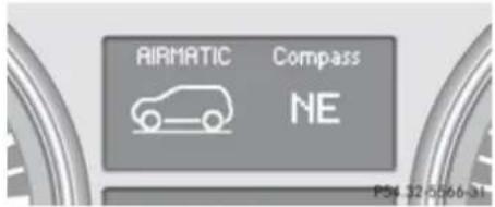
text_image
AIRMATIC Compass NE PS4 32-0566-81The vehicle is lowered to the highway level automatically if the vehicle speed is above 55 mph (88 km/h) or if the vehicle speed stays between 40 mph (64 km/h) and 55 mph (88 km/h) for approximately 20 seconds.
Vehicles with enhanced off-road package (Canada only)
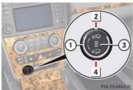
text_image
1 2 3 4 P54.25-6842-01① Rotatable outer adjustment ring
2 Set higher vehicle level
③ Indicator lamps
4 Set lower vehicle level
Basic settings
The following vehicle chassis ride heights can be selected using the vehicle level control switch in the center console:
| Level Driving situation |
| Off-road 3 Exclusively for clearing impracticable situations at low speed. Lower, middle and upper indicator lamps are on. |
| Off-road 2 Off-road driving. Lower and middle indicator lamps are on. |
| Off-road 1 For driving on easy terrain. Lower indicator lamp is on. |
| Highway For normal driving. Indicator lamps are off. |
Another available level is the highspeed level that is set automatically.
The following is the approximate change in ride height for each of the level settings:
Level Ride height
| Off-road 3 +3.5 in (90 mm) |
| Off-road 2 +2.3 in (60 mm) |
▶▶
Controls in detail
Driving systems
| Level Ride height | |
| Off-road 1 +1.2 in (30 mm) | |
| Highway9 | +/-0 in (0 mm) |
| Highspeed -0.6 in (-15 mm) | |
i Vehicles with ADS:
Depending on the ADS setting (▷ page 185), the vehicle will be lowered to the highspeed level when traveling at higher speeds. At speeds below 40 mph (64 km/h) at the latest, it will be returned to the highway level.
i The highspeed level is not available when towing a trailer. For more information on towing a trailer, see "Trailer towing" (▷ page 310).
You can only select the off-road levels below a certain speed. At higher speeds, the message Level Selection Not Permitted appears in the multifunction display.
You can select
- Off-road level 1: selectable below 60 mph (96 km/h)
- Off-road level 2: selectable below 40 mph (64 km/h)
- Off-road level 3: selectable below 12 mph (20 km/h)
Off-road levels
Warning!
Vehicle off-road level 3 is not intended for use on paved roads. This vehicle level is intended for clearing impracticable situations at low speed exclusively. The vehicle has a very high center of gravity in off-road level 3. This increases the overturning hazard.
- Select off-road level 3 exclusively for clearing impracticable situations at low speed.
- Adapt your driving style to the modified conditions.
-
Do not exceed a speed of 12 mph (20 km/h).
-
Avoid extreme, quick steering movements.
- Keep in mind the vehicle's driving characteristics are modified.
You should therefore drive in off-road level 3 with particular caution as it could otherwise lead to an accident and/or serious injury to you or others.
If you are driving too fast while using off-road level 3, you will see the following message in the multifunction display:
Reduce speed to under 12 MPH (20 km/h)
In addition, an acoustic signal sounds.
This message cannot be deactivated. For more information, see "Display messages" (▷ page 351)
Only use off-road levels when necessary. Otherwise the fuel consumption may increase and/or the handling characteristics of the vehicle may be unfavorable.
▶ Start the engine.
▶ Turn outer adjustment ring ① repeatedly until indicator lamp ③ of the desired level flashes.
Controls in detail
Driving systems
- Off-road level 1, lower indicator lamp flashes
- Off-road level 2, lower and middle indicator lamps flashes
- Off-road level 3, lower, middle and upper indicator lamps flashes
The vehicle adjusts to the corresponding off-road level. For example, the following message appears in the multifunction display while the level is being set:
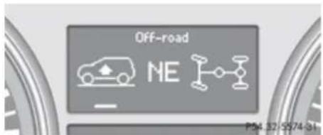
text_image
OFF-road NE P54.32 5874-31The vehicle is raised from off-road level 1 to off-road level 2.
The message can be cleared by pressing the 📄, 📅, or 🏠 button on the multifunction steering wheel.
When the off-road level 2 is reached, the following message appears in the multifunction display for 5 seconds:
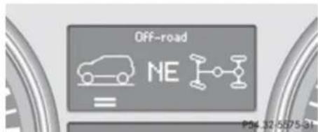
text_image
Off-road NE P4K 12-5875-31The lower and middle indicator lamps ③ comes on continuously.
While the vehicle is adjusting from off-road level 2 to off-road level 3, you will see, for example, the following message in the multifunction display:
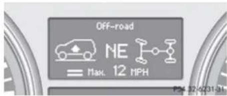
text_image
Off-road NE Max. 12 MPH P× 12-0231-31Once off-road level 3 is reached, you will see, for example, the following message in the multifunction display:
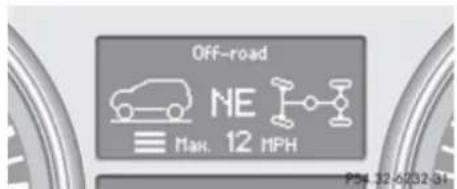
text_image
Off-road NE Max. 12 MPH PS4 12-0732-31The message Max. 12 MPH (20 km/h) reminds you of the maximum permissible driving speed with off-road level 3.
If you drive faster than 12 mph (20 km/h) for a short period while using off-road level 3, the following message appears in the multifunction display:
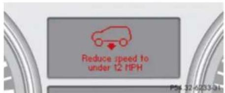
text_image
Reduce speed to under 12 HPH P54.12-6733-31Off-road level 3 is canceled.
If you continue to increase your speed, the message remains in the multifunction display.
The new level will not be shown until the vehicle has been able to adjust to a level
▶▶
Controls in detail
Driving systems
appropriate for the speed at which you are currently driving.
If you maintain or reduce your speed, you will see, for example, the following message in the multifunction display while the vehicle is lowering
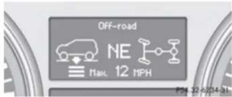
text_image
Off-road NE Max. 12 MPH P24 32-6/2024-31The vehicle is lowered to off-road level 2. Once off-road level 2 is reached, you will see, for example, the following message in the multifunction display:
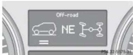
text_image
OFF-road NE P54 12-5075-01While driving, the vehicle is lowered automatically as follows:
- At vehicle speeds above 55 mph (88 km/h) or if the vehicle speed stays
between 40 mph (64 km/h) and 55 mph (88 km/h) for approximately 20 seconds, the off-road level 2 setting is canceled and the vehicle is lowered to the off-road level 1.
You will see, for example, the following message in the multifunction display:
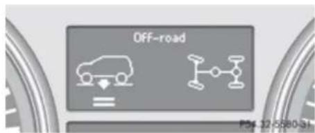
text_image
OFF-road P54 12-5880-31- At speeds above 60 mph (96 km/h) the off-road level 1 setting is canceled and the vehicle is lowered to the highway level. You will see, for example, the following message in the multifunction display:
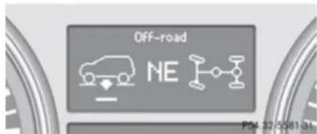
text_image
OFF-road NE P54 22-0081-04- Depending on the ADS setting (▷ page 185), the vehicle will be lowered to
the highspeed level when traveling at higher speeds. At speeds below 25 mph (40 km/h) at the latest, it will be returned to the highway level.
The setting is stored when you turn off the engine.
Highway level
! Keep in mind that on rough or uneven roads, adjusting the vehicle to a lower level may cause the vehicle underbody to come in contact with the road and result in damage to the vehicle underbody. Always make sure the vehicle has sufficient ground clearance before adjusting it to a lower level.
▶ Start the engine.
When one or more indicator lamps ③ are on:
▶ Turn outer adjustment ring ① until all lit indicator lamps ③ flash.
The vehicle adjusts to the highway level. The following message appears in the multifunction display while the level is being set:
Controls in detail
Driving systems
text_image
OFF-road NE PSX 32-0581-34The message can be cleared by pressing the 📄, 📅, or ▼ button on the multifunction steering wheel.
When the highway level is reached, the indicator lamps ③ go out and the following message appears in the multifunction display for 5 seconds:
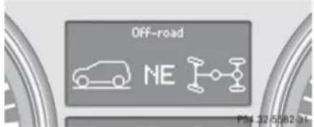
text_image
OFF-road NE P54 32 6582-31The vehicle is lowered to the highway level automatically if the vehicle speed is above 60 mph (96 km/h).
All-wheel drive
Your vehicle is equipped with all-wheel drive (4MATIC). Both, the front and rear axles, are powered at all times when the vehicle is being operated. The 4MATIC improves traction in conjunction with the ESP ^® (▷ page 77) and the Electronic Traction System (4-ETS) (▷ page 78).
Warning!
If a drive wheel is spinning due to insufficient traction:
- While driving off, apply as little throttle as possible.
- While driving, ease up on the accelerator pedal.
- Adapt your speed and driving style to the prevailing road conditions.
Failure to observe these guidelines could cause the vehicle to skid.
The 4MATIC cannot prevent accidents resulting from excessive speed.
! Do not tow with one axle raised. Doing so could damage the transfer case, which is not covered by the Mercedes-Benz Limited Warranty. All wheels must be on or off the
ground. Observe instructions for towing the vehicle with all wheels on the ground.
! Only conduct operational or performance tests on a two-axle dynamometer. If such tests are necessary, contact an authorized Mercedes-Benz Center. You could otherwise seriously damage the brake system and/or the transfer case which is not covered by the Mercedes-Benz Limited Warranty.
In winter operation, the maximum effectiveness of the 4MATIC is only achieved with winter tires (▷ page 297) or snow chains as required.
Parktronic system
The Parktronic system is an electronic parking aid with ultrasonic sensors designed to assist the driver during parking maneuvers. It indicates the relative distance between the vehicle and an obstacle visually and audibly. The Parktronic system is activated automatically when you
- switch on the ignition and
- release the parking brake
▶▶
Controls in detail
Driving systems
and
- the automatic transmission is in drive position D, reverse gear R, or neutral position N
The Parktronic system deactivates at speeds above approximately 11 mph (18 km/h). At lower speeds, the Parktronic system switches on again.
The Parktronic system also deactivates when you shift the automatic transmission into park position P or engage the parking brake.
The Parktronic system monitors the surroundings of your vehicle with six sensors in the front bumper and four sensors in the rear bumper.
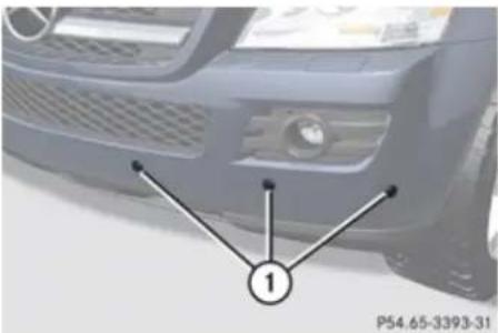
natural_image
Front view of a car's head with visible grille and headlights, marked with number 1 (no text or symbols on the car itself)① Sensors in the front bumper
To function properly, the sensors must be free of dirt, ice, snow and slush. Clean the sensors regularly, being careful not to scratch or damage the sensors, see "Cleaning the Parktronic system sensors" ( page 321).
Warning!
The Parktronic is a supplemental system. It is not intended to, nor does it replace, the need for extreme care. The responsibility during parking and other critical maneuvers always remains with the driver.
Warning!
Make sure no persons or animals are in or near the area in which you are parking/ maneuvering. Otherwise, they could be injured.
! Special attention must be paid to objects with smooth surfaces or low silhouettes (e.g. trailer couplings, painted posts, elevated crossbars or road curbs). Such objects may not be detected by the system and can damage the vehicle.
During parking maneuvers, pay special attention to objects located above or below the height of the sensors (e.g. street curbs, painted posts, or trailer hitches etc.). The Parktronic system will not detect such
objects at close range and damage to your vehicle or the object may result.
! Ultrasonic signals from outside sources (e.g. truck air brakes, car wash, or jackhammers) may impair the operation of the Parktronic system.
Range of the sensors

text_image
100 50 0 (cm) 40 20 0 (in ) 0 60 120 (cm) 0 24 48 (in ) P54.65-3394-31Controls in detail
Driving systems
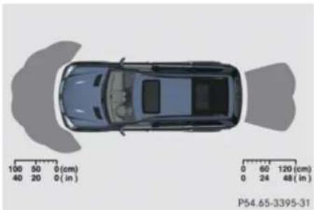
natural_image
Top-down view of a car with shadowed side and horizontal measurement scales (no text or symbols on the car itself)Front sensors
Center approx. 40 in (100 cm)
Corners approx. 24 in (60 cm)
Rear sensors
Center approx. 48 in (120 cm)
Corners approx. 32 in (80 cm)
Minimum distance
Center approx. 8 in (20 cm)
Corners approx. 6 in (15 cm)
If the Parktronic system detects an obstacle in this range, all the distance warning segments illuminate and you hear a warning signal. If the obstacle is closer than the minimum distance, the actual distance may no longer be indicated by the Parktronic system.
Warning indicators
Visual signals indicate to the driver the relative distance between the sensors and an obstacle.
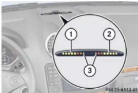
text_image
1 2 3 P54 25-6843-31Front area warning indicator
① Left side of the vehicle
② Right side of the vehicle
③ Readiness indicators
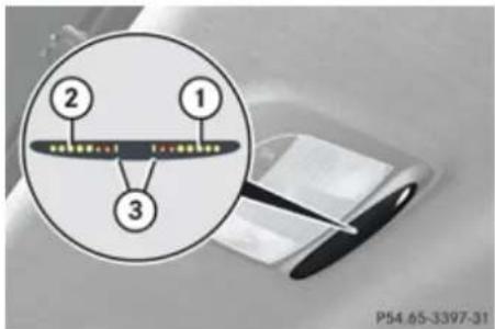
text_image
② ① ③ P54.65-3397-31Rear area warning indicator
① Left side of the vehicle
② Right side of the vehicle
③ Readiness indicators
Each warning indicator is divided into five yellow and two red distance segments for either side of the vehicle. The Parktronic system is ready to measure when the yellow readiness indicators ③ are illuminated.
The current transmission position determines which warning indicator will be activated.
Controls in detail
Driving systems
| Current transmission position | Warning indicator |
| D Front area activated | |
| R or N Front and rear area activated |
As your vehicle approaches an object, one or more distance segments will illuminate, depending on the distance. When the seventh distance segment illuminates, you have reached the minimum distance.
- Front area: An intermittent acoustic warning will sound as the first red distance segment illuminates and a constant acoustic warning lasting a maximum of 2 seconds will sound for the second red distance segment. The signal is canceled when the automatic transmission is shifted into park position P or the parking brake is engaged.
- Rear area: An intermittent acoustic warning will sound as the first red distance segment illuminates and a constant acoustic warning lasting a maximum of 2 seconds will sound for the second red distance segment. The signal is canceled
when the automatic transmission is shifted into drive position D, or park position P, or the parking brake is engaged.
Switching the Parktronic system on/off
The Parktronic system switches on automatically when the ignition is switched on.
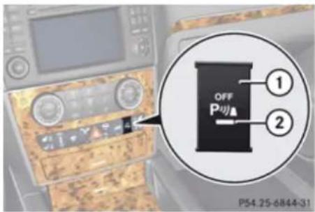
text_image
OFF P ① ② P54.25-6844-31Vehicle without enhanced off-road package
① Parktronic switch
② Indicator lamp
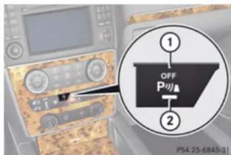
text_image
OFF P ① ② P54.25-6845-31Vehicle with enhanced off-road package
① Parktronic switch
② Indicator lamp
Switching off Parktronic system: Press Parktronic switch ①.
Indicator lamp ② comes on.
Switching on Parktronic system: Press Parktronic switch ① again.
i Vehicles with original equipment Mercedes-Benz Trailer Hitch Kit: The rear Parktronic sensor will disengage automatically when towing a trailer.
Controls in detail
Driving systems
Parktronic system malfunction
There is a malfunction in the Parktronic system, if only the red distance segments illuminate and an acoustic warning sounds. The Parktronic system will switch off automatically after 20 seconds and indicator lamp ② in Parktronic switch ① comes on.
▶ Have the Parktronic system checked at an authorized Mercedes-Benz Center as soon as possible.
If only the red distance segments illuminate and no acoustic warning sounds, the Parktronic system sensors are dirty (e.g. dirt, ice, snow and slush) or there is an interference from other radio or ultrasonic signals (e.g. truck air brakes, car wash, or jackhammers). The Parktronic system will switch off automatically after 20 seconds and indicator lamp ② in Parktronic switch ① comes on.
▶ Switch off the ignition.
▶ Clean the Parktronic system sensors ( page 321).
▶ Switch on the ignition.
or
▶ Check the Parktronic system operation at another location to rule out interference from outside radio or ultrasonic signals.
Rear view camera
Warning!
The rear view camera is only an aid and may display obstacles from a distorted perspective or inaccurately, or may not display obstacles at all. The rear view camera does not relieve you of the responsibility to be cautious, take care and pay careful attention. The rear view camera may not show objects which are
• very close to the rear bumper
• under the rear bumper
• above the tailgate handle
You are responsible for safety at all times and must continue to pay attention to the immediate surroundings when parking and maneuvering. This includes the area behind, in front of and beside the vehicle. Otherwise you could endanger yourself and/or others.
Warning!
Make sure no persons or animals are in or near the area in which you are parking/maneuvering. Otherwise, they could be injured.
Warning!
The rear view camera either will not function or will not function to its full capability if
- the tailgate is open
- it is raining very hard, snowing or foggy
- it is night or you are parking/ maneuvering your vehicle in an area where it is very dark
- the camera is exposed to a very bright white light
• the immediate surroundings are illuminated with fluorescent light (the display may flicker)
- there is a sudden change in temperature, e.g. if you drive into a heated garage from the cold (lens condensation)
• the camera lens is dirty or covered
• the rear of your vehicle is damaged
Controls in detail
Driving systems
In this case, have the position and setting of the camera checked by a qualified specialist workshop. Mercedes-Benz recommends that you contact a Mercedes-Benz Center for this purpose.
Do not use the rear view camera in these situations. Otherwise you could injure yourself or others and/or damage property including your vehicle while parking/maneuvering.
The rear view camera is an optical parking aid. It shows you the area behind the vehicle in the COMAND system display when reverse gear R is engaged, for example during parallel parking.
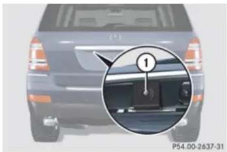
natural_image
Back view of a car with a close-up inset showing a component detail (no visible text or symbols)① Rear view camera
▶ Switching on: Switch on the ignition.
▶ Switch on the COMAND system.
▶ Shift the automatic transmission to reverse gear R.
The area behind the vehicle appears in the COMAND system display.
The area behind the vehicle is shown in the COMAND system display as a mirror image, like in the rear view mirror.
The image from the rear view camera will no longer be displayed if you select another function on the COMAND system while reverse gear R is engaged. To display the image again, disengage and reengage reverse gear R.
Switching off: Shift the automatic transmission into park position P, neutral position N, or drive position D.
Overview of climate control system functions and air vents
Your vehicle is equipped with either of the following climate control systems:
Climate control 3-zone automatic climate control
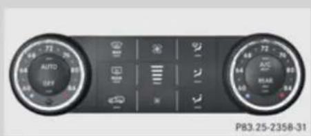
text_image
AUTO OFF P83.25-2358-31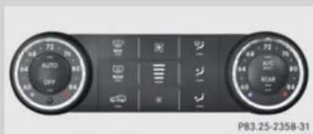
natural_image
Front view of a car dashboard with two rotary gauges and control buttons (no readable text or symbols)USA only
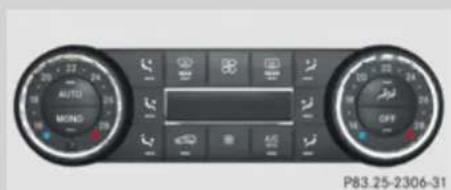
text_image
AUTO MOND OFF P83.25-2306-31Rear automatic climate control
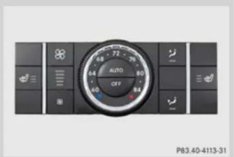
text_image
AUTO OFF P83.40-4113-31Canada only
The climate control combines an automatic heating and ventilation system with a cooling system. You can adjust the automatic climate control separately for the driver's and passenger side.
The 3-zone automatic climate control combines an automatic heating and ventilation system with a cooling system. You can adjust the 3-zone automatic climate control separately for each zone in the vehicle.
The rear-automatic climate control allows separate climate settings for the rear compartment.
Controls in detail
Overview of climate control system functions and air vents
Air vents

Warning!
When operating the climate control, the air that enters the passenger compartment through the air vents can be very hot or very cold (depending on the set temperature). This may cause burns or frostbite to unprotected skin in the immediate area of the air vents.
Always keep sufficient distance between unprotected parts of the body and the air vents. If necessary, use the air distribution adjustment to direct the air to air vents in the vehicle interior that are not in the immediate area of unprotected skin.
For best possible performance of the climate control:
- Keep the air intake grille in front of the windshield free of snow, leaves, sticks, and any other debris.
▶ Always keep all air vents and grilles in the passenger compartment free from obstruction.
For draft-free ventilation, move the adjustable center and side air vents to the middle position.
Center air vents
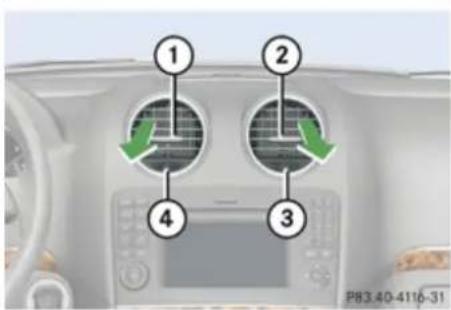
text_image
1 2 3 4 P83.40-4116-31① Left center air vent, adjustable
② Right center air vent, adjustable
③ Thumbwheel for air volume control for adjustable right center air vent
④ Thumbwheel for air volume control for adjustable left center air vent
▶ Opening/closing: Turn thumbwheels ③ and ④ in the required direction.
Side air vents
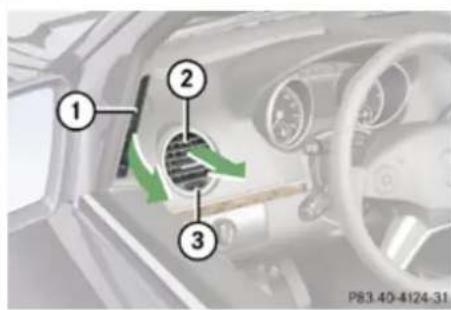
text_image
Diagram of car air intake system with numbered components and directional arrows indicating airflow or movementExample illustration driver's side
① Left side defroster air vent, fixed
② Left side air vent, adjustable
③ Thumbwheel for air volume control for adjustable left side air vent
Opening/closing: Turn thumbwheel ③ in the required direction.
Controls in detail
Overview of climate control system functions and air vents
Rear center console air vents
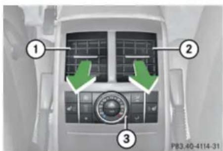
text_image
① ② ③ P83.40-4114-31① Left rear center air vent, adjustable
② Right rear center air vent, adjustable
③ Rear climate control panel
When the front climate control panel is switched on or off, the air supply through the rear center air vents is also switched on or off.
Air vents in the roof liner over the second-row seats
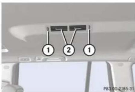
text_image
① ② ① P83 00-2185-31Vehicles with 3-zone automatic climate control only
① Thumbwheel for air volume control
② Air vent, adjustable
▶ Opening/closing: Turn thumbwheels ① upward or downward.
Air vents in the roof liner over the third-row seats
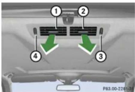
text_image
① ② ③ ④ P83.00-2261-35Vehicles with 3-zone automatic climate control only
① Left air vent, adjustable
② Right air vent, adjustable
③ Thumbwheel for air volume control for adjustable right air vent
④ Thumbwheel for air volume control for adjustable left air vent
▶ Opening/closing: Turn thumbwheels ③ and ④ upward or downward.
Controls in detail
Climate control
Climate control
Control panel
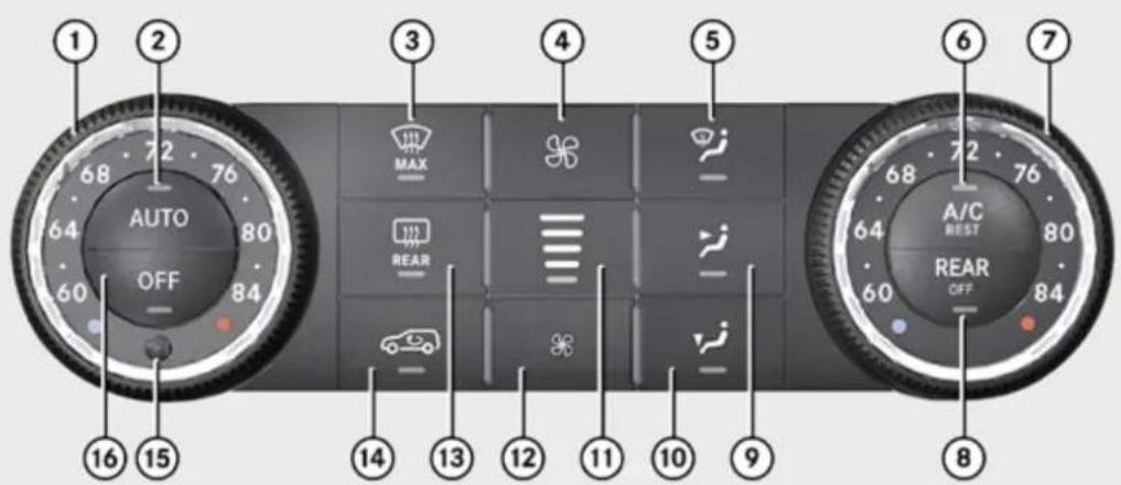
text_image
1 2 3 4 5 6 7 AUTO MAX REAR A/C REST REAR OFF 68 72 76 64 80 60 84 16 15 14 13 12 11 10 9 60 84P83.30-4607-31
| Function Recommendation/Notes | |||
| 1 | Temperature control, driver's side | i Set the temperature to 72°F (22°C). | (▷ page 207) |
| 2 | AUTO Air distribution and air volume (automatic mode) | i Switches on the automatic mode. The indicator lamp in button AUTO comes on. | (▷ page 206) |
Controls in detail
Climate control
| Function Recommendation/Notes | |||
| 3 | Front defroster | Keep this setting selected only until the windshield or the side windows are clear again. | (▷ page 207) |
| 4 | Increasing air volume (▷ page 207) | ||
| 5 | Air distribution (directs air through the windshield and side air vents) | (▷ page 207) | |
| 6 | AC cooling on/off | Switches on the air conditioning. The indicator lamp in button comes on. | (▷ page 206) |
| Residual heat/ventilation | With the engine turned off, it is possible to continue to heat or ventilate the interior. | (▷ page 209) | |
| 7 | Temperature control, passenger side | Set the temperature to 72°F (22°C). | (▷ page 207) |
| 8 | Rear climate control on/off or air supply for rear passenger compartment on/off (USA only) | ||
| Rear climate control on/off or air supply for rear passenger compartment on/off (Canada only) | |||
| 9 | Air distribution (directs air through center and side air vents) | (▷ page 207) | |
| 10 | Air distribution (directs air through the footwells and side air vents) | (▷ page 207) |
▶▶
Controls in detail
Climate control
| Function Recommendation/Notes | |||
| 11 | Air volume display | ||
| 12 | Decreasing air volume (▷ page 207) | ||
| 13 | Rear window defroster | i At very low temperatures, rear window defroster operation is delayed until the vehicle interior has warmed up. | (▷ page 223) |
| 14 | Air recirculation | i Only use this function for a short time, e.g. in a tunnel.(▷ page 208) Otherwise, the windows can fog up due to lack of fresh air. | |
| 15 | Interior temperature sensor | ||
| 16 | OFF Climate control on/off | i Switches on the climate control system. The indicator (▷ page 205) lamp in button OFF goes out. |
Controls in detail
Climate control
Notes on climate control
The climate control is operational whenever the engine is running. You can operate the climate control system in either the automatic or manual mode. The system cools or heats the interior depending on the selected interior temperature and the current outside temperature.
Nearly all dust particles, pollutants and odors are filtered out before outside air enters the passenger compartment through the air distribution system.

Warning!
Severe conditions (e.g. strong air pollution) may require replacement of the filter before its scheduled replacement interval. A clogged filter will reduce the air volume to the interior and the windows could fog up, impairing visibility and endangering you and others. Have a clogged filter replaced as soon as possible at an authorized Mercedes-Benz Center.
The air conditioning will not engage (no cooling) if the A/C mode is deactivated (▷ page 206).

Warning!
Follow the recommended settings for heating and cooling given on the following pages. Otherwise the windows could fog up, impairing visibility and endangering you and others.
Keep the air intake grille in front of the windshield free of snow and debris.
If the vehicle interior is hot, ventilate the interior before driving off, see “Summer opening feature” ( page 127). The climate control will then adjust the interior temperature to the set value much faster.
Deactivating the climate control system

Warning!
When the climate control system is switched off, the outside air supply and circulation are also switched off. Only choose this setting for a short time. Otherwise the windows could fog up, impairing visibility and endangering you and others.
▶ Deactivating: Press button OFF.
The indicator lamp in the button comes on.
▶ Reactivating: Press button AUTO.
You can also press button OFF on the climate control panel.
If you press button 📁 to reactivate the climate control system, the defrosting mode is activated.
Deactivating the rear climate control from the front
▶ Deactivating: Press button REAR OFF
The indicator lamp in the button comes on.
▶ Reactivating: Press button REAR OFF.
The indicator lamp in the button goes out.
Controls in detail
Climate control
Air conditioning
The air conditioning is operational while the engine is running and cools the interior air to the temperature set by the operator. In addition, the air conditioning dehumidifies the interior air and helps prevent window fogging.
Warning!
If you switch off the cooling function, the vehicle will not be cooled when weather conditions are warm. The windows can fog up more quickly. Window fogging may impair visibility and endanger you and others.
i Condensation may drip out from underneath the vehicle. This is normal and not an indication of a malfunction.
Deactivating
It is possible to deactivate the air conditioning. The interior air will then no longer be cooled or dehumidified.
▶ Press button A/C
The indicator lamp in the button goes out. The cooling function switches off after a short delay.
Activating
Moist air can fog up the windows. You can dehumidify the interior air with the air conditioning.
▶ Press button A/C again.
The indicator lamp in the button comes on.
The air conditioning uses the refrigerant R134a. This refrigerant is free of CFCs which are harmful to the ozone layer.
! If the air conditioning cannot be activated again, this indicates that the air conditioning is losing refrigerant. The compressor has turned off. Have the air conditioning checked at the nearest authorized Mercedes-Benz Center.
Automatic mode
When operating the climate control system in automatic mode, the interior air temperature, air volume and air distribution are adjusted automatically.
In automatic mode, cooling with dehumidification is switched on. This function can be switched off if necessary.
Warning!
If you switch off the cooling function, the vehicle will not be cooled when weather conditions are warm. The windows can fog up more quickly. Window fogging may impair visibility and endanger you and others.
▶ Set the desired temperature (▷ page 207).
▶ Activating: Press button AUTO. The indicator lamp in the button comes on. The air volume and air distribution are adjusted automatically.
i The settings for the passenger side are also used for the rear passenger compartment.
Controls in detail
Climate control
▶ Deactivating: Press button 🧿 or 🏱.
The indicator lamp in button AUTO goes out. The automatic operation of air volume switches off. The selected blower speed is shown in air volume display ⑪ (> page 202).
or
▶ Press air distribution button 📞, 🚗, or 📄.
The indicator lamp in button AUTO goes out. The automatic operation of air distribution switches off.
Setting the temperature
You can adjust the air temperature on each side of the passenger compartment. You should raise or lower the temperature setting in small increments, preferably starting at 72^ F ( 22^ C).
▶ Increasing/decreasing: Turn temperature control ① and/or ⑦ (▶ page 202) slightly clockwise or counterclockwise.
Adjusting air distribution
The air distribution can be adjusted manually. The symbols on the buttons represent the following functions:
Symbol Function
| Directs air to the windshield and side air vents | |
| Directs air through the center and side air vents | |
| Directs air to the footwells and side air vents |
▶ Press the desired air distribution button

The indicator lamp in button AUTO goes out. The automatic mode is switched off. Air distribution is controlled according to the desired button.
Adjusting air volume
▶ Decrease/increase: Press button 📄 or 🌐.
The automatic mode is switched off. The selected blower speed is shown in air volume display ⑪ (▷ page 202).
Front defroster
You can use this setting to defrost the windshield, for example if it is iced up. You can also defog the windshield and the side windows.
Keep this setting selected only until the windshield or the side windows are clear again.
Activating
▶ Press button 📄. The indicator lamp in the button comes on. The climate control switches to the following functions automatically:
Controls in detail
Climate control
- most efficient blower speed and heating power, depending on outside temperature
- air flows onto the windshield and the front door windows (side air vents must be open)
- the air conditioning compressor switches on at outside temperatures above approximately 41°F (5°C) for air-drying
Adjustments
You can adjust the air volume and the temperature when the front defroster is switched on. The air flow will remain on the windshield and front door windows.
▶ Press button ☑ to decrease or button ☑ to increase air volume to the desired level.
The air volume decreases/increases to the next lower/higher blower speed and heating switches to the temperature that was set before the front defroster was switched on.
The indicator lamp in button 📁️ goes out. The indicator lamp in button A/C comes on.
or
▶ Turn temperature control ① and/or ⑦ (▷ page 202) slightly in any direction. Heating switches to the temperature that was set before the front defroster was switched on.
The indicator lamp in button goes out. The indicator lamp in button A/C comes on.
The air conditioning compressor remains on even if the indicator lamp in button goes out. This helps to prevent the windshield from fogging.
Deactivating
▶ Press button 📄 again.
The indicator lamp in the button goes out. Defrosting is turned off.
The previous settings are once again in effect. The air conditioning compressor remains switched on.
To deactivate, you can also press button OFF or AUTO.
Windshield fogged on the outside
▶ Switch the windshield wipers on (▷ page 122).
▶ Press air distribution button ↗ or ↙.
Air recirculation mode
Switch to air recirculation mode to prevent unpleasant odors from entering the vehicle from the outside (e.g. before driving through a tunnel). This setting cuts off the intake of outside air and recirculates the air in the passenger compartment.

Warning!
Fogged windows impair visibility, endangering you and others. If the windows begin to fog on the inside, switching off the air recirculation mode immediately should clear interior window fogging. If interior window fogging persists, make sure the air conditioning is activated, or press button
▶ Activating: Press button 📄. The indicator lamp in the button comes on.
i The air recirculation mode is activated automatically at high outside temperatures.
The indicator lamp in button is not lit when the air recirculation mode is switched on automatically.
A quantity of outside air is added after approximately 30 minutes.
If you have turned off the air conditioning or the outside temperature is below 41^ F ( 5^ C), the air recirculation mode will not switch on automatically.
▶ Deactivating: Press button
The indicator lamp in the button goes out.
i The manually selected air recirculation mode is deactivated automatically:
• after 5 minutes if the outside temperature is below approximately 41°F (5°C)
• after 5 minutes if the air conditioning and air-drying are turned off
• after 30 minutes if the outside temperature is above approximately 41°F (5°C)
Residual heat and ventilation
With the engine switched off, it is possible to continue to heat or ventilate the interior for up to 30 minutes. This feature makes use of the residual heat produced by the engine.
How long the system will provide heating depends on the coolant temperature and the battery voltage.
Regardless of the temperature and air volume set on the climate control panel, an interior temperature is aimed at by 72^ F ( 22^ C) and the blower runs on low speed to protect the vehicle battery.
▶ Activating: Switch off the ignition.
▶ Press button A/C REST.
The indicator lamp in the button comes on.
▶ Deactivating: Press button A/C test again.
The indicator lamp in the button goes out.
The residual heat is deactivated automatically:
- when the ignition is switched on
• after approximately 30 minutes
• if the battery voltage drops - if the coolant temperature is too low
Controls in detail
3-zone automatic climate control
3-zone automatic climate control
Control panels
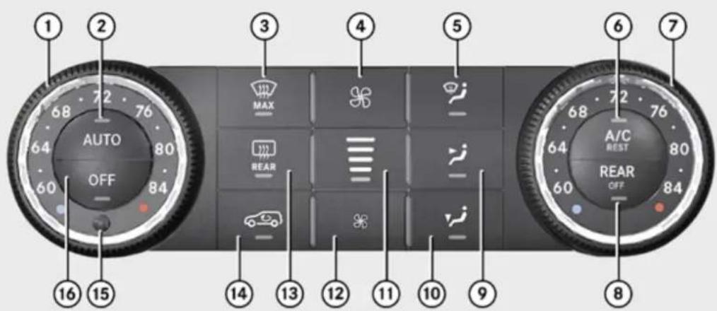
text_image
1 2 3 4 5 6 7 AUTO MAX REAR A/C REST REAR OFF 68 72 76 64 80 60 84 16 15 14 13 12 11 10 9 68 72 76 64 80 60 84 8P83.30-4607-31
USA only
Controls in detail
3-zone automatic climate control
| Function Recommendation/Notes | |||
| 1 | Temperature control, driver's side | i Set the temperature to 72°F (22°C). | (▷ page 219) |
| 2 | AUTO Air distribution and air volume (automatic mode) | i Switches on the automatic mode. The indicator lamp in button AUTO comes on. | (▷ page 218) |
| 3 | Front defroster | i Keep this setting selected only until the windshield or the side windows are clear again. | (▷ page 221) |
| 4 | Increasing air volume (▷ page 221) | ||
| 5 | Air distribution (directs air through the windshield and side air vents) | (▷ page 220) | |
| 6 | A/C AC cooling on/off | i Switches on the air conditioning. The indicator lamp in button A/C comes on. | (▷ page 217) |
| A/C Residual heat/ventilation | i With the engine turned off, it is possible to continue to heat or ventilate the interior. | (▷ page 223) | |
| 7 | Temperature control, passenger side | i Set the temperature to 72°F (22°C). | (▷ page 219) |
| 8 | REAR Operating the rear climate control from the front | (▷ page 217) | |
| 9 | Air distribution (directs air through center and side air vents) | (▷ page 220) |
▶▶
Controls in detail
3-zone automatic climate control
| Function Recommendation/Notes | |||
| 10 | Air distribution (directs air through the footwells and side air vents) | (▷ page 220) | |
| 11 | Air volume display | ||
| 12 | Decreasing air volume (▷ page 221) | ||
| 13 | Rear window defroster | i At very low temperatures, rear window defroster operation is delayed until the vehicle interior has warmed up. | (▷ page 223) |
| 14 | Air recirculation | i Only use this function for a short time, e.g. in a tunnel.(▷ page 222) Otherwise, the windows can fog up due to lack of fresh air. | |
| 15 | Interior temperature sensor | ||
| 16 | OFF Climate control on/off | i Switches on the climate control system. The indicator lamp in button OFF goes out. | (▷ page 217) |
Controls in detail
3-zone automatic climate control
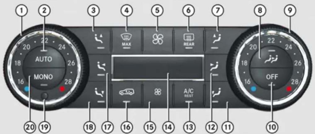
text_image
1 2 3 4 5 6 7 8 9 AUTO MONO 20 19 18 17 16 15 14 13 12 11 MAX REAR OFF 20 22 24 26 28 16 18 17 16 15 14 13 12 11P83.40-3806-31
Canada only
| Function Recommendation/Notes | |||
| 1 | Temperature control, driver's side | i Set the temperature to 72°F (22°C). | (▷ page 219) |
| 2 | AUTO Air distribution and air volume (automatic mode) | i Switches on the automatic mode. The indicator lamp in button AUTO comes on. | (▷ page 218) |
| 3 | Air distribution, driver's side (directs air through the windshield and side air vents) | (▷ page 220) |
▶▶
Controls in detail
3-zone automatic climate control
| Function Recommendation/Notes | |||
| 4 | Front defroster | Keep this setting selected only until the windshield or the side windows are clear again. | (> page 221) |
| 5 | Increasing air volume (> page 221) | ||
| 6 | Rear window defroster | At very low temperatures, rear window defroster operation is delayed until the vehicle interior has warmed up. | (> page 223) |
| 7 | Air distribution, passenger side (directs air through the windshield and side air vents) | (> page 220) | |
| 8 | Operating the rear climate control from the front | (> page 217) | |
| 9 | Temperature control, passenger side | Set the temperature to 72°F (22°C). | (> page 219) |
| 10 | OFF Automatic climate control on/off | Switches on the climate control system. The indicator lamp in button OFF goes out. | (> page 217) |
| 11 | Air distribution, passenger side (directs air through the footwells and side air vents) | (> page 220) | |
| 12 | Air distribution, passenger side (directs air through center and side air vents) | (> page 220) |
Controls in detail
3-zone automatic climate control
| Function Recommendation/Notes | |||
| 13 | AC cooling on/off | Switches on the air conditioning. The indicator lamp in button comes on. | (▷ page 217) |
| Residual heat ventilation | With the engine turned off, it is possible to continue to heat or ventilate the interior. | (▷ page 223) | |
| 14 | Display | ||
| 15 | Decreasing air volume (▷ page 221) | ||
| 16 | Air recirculation | Only use this function for a short time, e.g. in a tunnel.(▷ page 222) Otherwise, the windows can fog up due to lack of fresh air. | |
| 17 | Air distribution, driver's side (directs air through center and side air vents) | (▷ page 220) | |
| 18 | Air distribution, driver's side (directs air through the footwells and side air vents) | (▷ page 220) | |
| 19 | Interior temperature sensor | ||
| 20 | Adopting driver's side settings for all zones | (▷ page 223) |
Controls in detail
3-zone automatic climate control
Rear automatic climate control
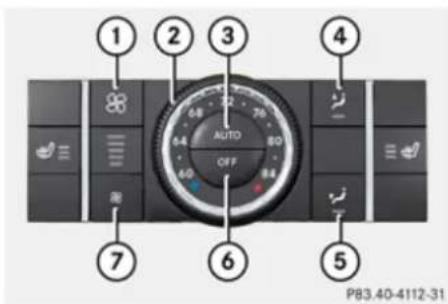
text_image
1 2 3 4 AUTO OFF 7 6 5 P83.40-4112-31① Increasing air volume
② Temperature control
③ Air distribution and air volume (automatic mode)
④ Air distribution (directs air through the side air vents)
⑤ Air distribution (directs air through the footwells and side air vents)
⑥ Rear automatic climate control on/off
⑦ Decreasing air volume
Notes on 3-zone automatic climate control
With the help of a sun sensor, the automatic climate control determines the relation of the sun to the vehicle and automatically adjusts the inside temperature for every individual zone.
The automatic climate control is operational whenever the engine is running. It cools the vehicle's interior according to the angle and intensity of the sun's rays, the outside temperature and the selected temperature. You can operate the automatic climate control in either the automatic or manual mode.
Nearly all dust particles, pollutants and odors are filtered out before outside air enters the passenger compartment through the air distribution system.
Warning!
Severe conditions (e.g. strong air pollution) may require replacement of the filter before its scheduled replacement interval. A clogged filter will reduce the air volume to the interior and the windows could fog up, impairing visibility and endangering you and others. Have a clogged filter replaced
as soon as possible at an authorized Mercedes-Benz Center.
The air conditioning will not engage (no cooling) if the A/C mode is deactivated (▷ page 217).
Warning!
Follow the recommended settings for heating and cooling given on the following pages. Otherwise the windows could fog up, impairing visibility and endangering you and others.
Keep the air intake grille in front of the windshield free of snow and debris.
If the vehicle interior is hot, ventilate the interior before driving off, see "Summer opening feature" (▷ page 127). The climate control will then adjust the interior temperature to the set value much faster.
Deactivating the climate control system

Warning!
When the climate control system is switched off, the outside air supply and circulation are also switched off. Only choose this setting for a short time. Otherwise the windows could fog up, impairing visibility and endangering you and others.
Deactivating the front climate control
▶ Deactivating: Press button OFF.
The indicator lamp in the button comes on.
Canada only: Display ⑭ (▷ page 213) is cleared.
▶ Reactivating: Press button AUTO.
You can also press button OFF on the climate control panel.
If you press button 📁 to reactivate the climate control system, the defrosting mode is activated.
Deactivating the rear climate control from the front
USA only
▶ Deactivating: Press button REAR OFF
The indicator lamp in the button comes on.
▶ Reactivating: Press button REAR OFF.
The indicator lamp in the button goes out.
Canada only
▶ Deactivating: Press button 🎨.
The indicator lamp in the button comes on. In display ⑭ (▶ page 213), you will see the ⚫ symbol followed by MODE for approximately 3 seconds.
▶ Press button OFF.
In display ⑭, you will see the √ symbol followed by OFF. The rear climate control is switched off.
▶ Reactivating: Press button 🎯.
The indicator lamp in the button comes on. In display ⑭, you will see the symbol followed by ON and MODE. The MODE display is cleared and the indicator lamp in button goes out after approximately 3 seconds.
The rear climate control switches on.
3-zone automatic climate control
Deactivating the rear climate control from the rear
▶ Deactivating: Press button OFF.
The indicator lamp in the button comes on.
▶ Reactivating: Press button AUTO.
The indicator lamp in the button comes on.
Air conditioning
The air conditioning is operational while the engine is running and cools the interior air to the temperature set by the operator. In addition, the air conditioning dehumidifies the interior air and helps prevent window fogging.
Warning!
If you switch off the cooling function, the vehicle will not be cooled when weather conditions are warm. The windows can fog up more quickly. Window fogging may impair visibility and endanger you and others.
i Condensation may drip out from underneath the vehicle. This is normal and not an indication of a malfunction.
Controls in detail
3-zone automatic climate control
Deactivating
It is possible to deactivate the cooling function of the climate control system. The interior air will then no longer be cooled or dehumidified.
▶ Press button A/C BEST.
The indicator lamp in the button goes out. The cooling function switches off after a short delay.
Activating
Moist air can fog up the windows. You can dehumidify the interior air with the air conditioning.
▶ Press button A/C again.
The indicator lamp in the button comes on.
The air conditioning uses the refrigerant R134a. This refrigerant is free of CFCs which are harmful to the ozone layer.
! If the air conditioning cannot be activated again, this indicates that the air conditioning is losing refrigerant. The compressor has turned off.
Have the air conditioning checked at the nearest authorized Mercedes-Benz Center.
Automatic mode
You can switch the climate control system on and off for each zone of the passenger compartment as desired.
When operating the climate control system in automatic mode, the interior air temperature, air volume and air distribution are adjusted automatically.
In automatic mode, cooling with dehumidification is switched on. This function can be switched off if necessary.
Warning!
If you switch off the cooling function, the vehicle will not be cooled when weather conditions are warm. The windows can fog up more quickly. Window fogging may impair visibility and endanger you and others.
▶ Set the desired temperature (▷ page 219).
▶ Activating: Press button AUTO. The indicator lamp in the button comes on.
i The settings for the passenger side are also used for the rear passenger compartment.
▶ Deactivating: Press button 🎨 or 🎨. The indicator lamp in button AUTO goes out. The automatic air volume is switched off and is controlled according to the desired setting. The automatic air distribution remains switched on.
or
▶ Press one air distribution button ^10 , ^10 , ^10 , ^11 , ^10 or
The indicator lamp in button AUTO goes out. The automatic air distribution is switched off and is controlled according to the desired position. The automatic air volume remains switched on.
^10 Canada only
11 USA only
Automatic mode with rear climate control panel
▶ Activating: Press button AUTO.
The indicator lamp in the button comes on. The temperature, air volume and air distribution are adjusted automatically.
▶ Deactivating: Press button 🎨 or 🌐
The automatic air volume is switched off and is controlled according to the desired setting. The automatic air distribution remains switched on.
or
▶ Press button ↗ or ↗.
The automatic air distribution is switched off and is controlled according to the desired position. The automatic air volume remains switched on.
Setting the temperature
You can set the air temperature for each of the 3 zones separately. You should raise or lower the temperature setting in small increments, preferably starting at 72^ F ( 22^ C).
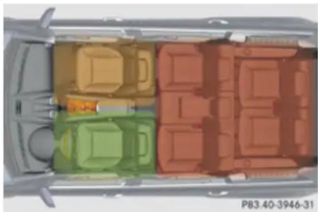
natural_image
Top-down architectural rendering of a car interior with colored compartments (no text or symbols visible)Front temperature with front climate control panel
USA only
▶ Increasing/decreasing: Turn temperature control ① and/or ⑦ (▷ page 210) slightly clockwise or counterclockwise.
3-zone automatic climate control
Canada only
▶ Increasing/decreasing: Turn temperature control ① and/or ⑨ (▶ page 213) slightly clockwise or counterclockwise.
Rear temperature with front climate control panel
▶ Press button REAR (USA only) or 📄 (Canada only). Canada only: In display 14 (▷ page 2 13) you will see the 📄 symbol.
USA only
▶ Increasing/decreasing: Turn temperature control ⑦ (▷ page 210) slightly clockwise or counterclockwise.
Canada only
▶ Increasing/decreasing: Turn temperature control ⑨ (▷ page 213) slightly clockwise or counterclockwise.
Controls in detail
3-zone automatic climate control
Rear temperature with rear climate control panel
▶ Increasing/decreasing: Turn temperature control ② (▷ page 216) slightly clockwise or counterclockwise.
Adjusting air distribution
USA only
The air distribution can be adjusted manually. The symbols on the buttons represent the following functions:
| Symbol Function | |
| Directs air to the windshield and side air vents | |
| Directs air through the center and side air vents | |
| Directs air to the footwells and side air vents | |
▶ Press the desired air distribution button 📂, 📋, or 📁. The automatic mode is switched off. The indicator lamp in the desired button comes on.
Canada only
The air distribution can be adjusted separately on each side of the passenger compartment.
The symbols on the buttons represent the following functions:
| Symbol Driver's side | Symbol Passenger side | Function |
| Directs air to the windshield and side air vents | ||
| Directs air through the center, side and rear passenger compartment air vents | ||
| Directs air to the footwells and side air vents |
Press the desired air distribution button 📁, 📋, or 📄 for the driver's side, or 📇, 🌐, or 🌒 for the passenger side. The automatic mode is switched off. The indicator lamp in the desired button comes on.
Adjusting air volume
USA only
▶ Decrease/increase: Press button 📄 or 🌐.
The automatic mode is switched off. The selected blower speed is shown in air volume display ⑪ (▷ page 210).
Canada only
▶ Decrease/increase: Press button 📄 or 🌐.
The automatic mode is switched off. The selected blower speed appears in display ⑭ (▷ page 213).
Front defroster
You can use this setting to defrost the windshield, for example if it is iced up.
You can also defog the windshield and the side windows.
Keep this setting selected only until the windshield or the side windows are clear again.
Activating
▶ Press button 📄.
The indicator lamp in the button comes on. The climate control switches to the following functions automatically:
- most efficient blower speed and heating power, depending on outside temperature
- air flows onto the windshield and the front door windows (side air vents must be open)
- the air conditioning compressor switches on at outside temperatures above approximately 41^ (5°C) for air-drying
Adjustments
You can adjust the air volume and the temperature when the front defroster is switched on. The air flow will remain on the windshield and front door windows.
▶ Press button ☑ to decrease or button ☑ to increase air volume to the desired level.
The air volume decreases/increases to the next lower/higher blower speed and heating switches to the temperature that
3-zone automatic climate control
was set before the front defroster was switched on.
The indicator lamp in button goes out. The indicator lamp in button A/C comes on.
or
▶ Turn temperature control ① and/or ⑦ (USA only) (▷ page 210) or ① and/or ⑨ (Canada only) (▷ page 213) slightly in any direction.
Heating switches to the temperature that was set before the front defroster was switched on.
The indicator lamp in button 🎨 goes out. The indicator lamp in button A/C comes on.
The air conditioning compressor remains on even if the indicator lamp in button goes out. This helps to prevent the windshield from fogging.
Deactivating
▶ Press button once more.
The indicator lamp in the button goes out. Defrosting is turned off.
▶▶
Controls in detail
3-zone automatic climate control
The previous settings are once again in effect. The air conditioning compressor remains switched on.
To deactivate, you can also press button OFF or AUTO.
Windshield fogged on the outside
▶ Switch the windshield wipers on (▷ page 122).
▶ Press button AUTO.
The indicator lamp in the button goes out. Air volume and air distribution are controlled separately for each zone.
If the automatic air volume and air distribution are switched off:
▶ Press buttons / 12 and / 12.
Air recirculation mode
Switch to air recirculation mode to prevent unpleasant odors from entering the vehicle from the outside (e.g. before driving through a tunnel). This setting cuts off the intake of outside air and recirculates the air in the passenger compartment.
Warning!
Fogged windows impair visibility, endangering you and others. If the windows begin to fog on the inside, switching off the air recirculation mode immediately should clear interior window fogging. If interior window fogging persists, make sure the air conditioning is activated, or press button

▶ Activating: Press button 📄. The indicator lamp in the button comes on.
The air recirculation mode is activated automatically at high outside temperatures.
The indicator lamp in button is not lit when the air recirculation mode is switched on automatically.
A quantity of outside air is added after approximately 30 minutes.
If you have turned off the air conditioning or the outside temperature is below 41^ F ( 5^ C), the air recirculation mode will not switch on automatically.
▶ Deactivating: Press button 📄. The indicator lamp in the button goes out.
i The manually selected air recirculation mode is deactivated automatically:
• after 5 minutes if the outside temperature is below approximately 41°F (5°C)
• after 5 minutes if the air conditioning and air-drying are turned off
• after 30 minutes if the outside temperature is above approximately 41°F (5°C)
At outside temperatures above 79^ F ( 26^ C) the system will not automatically switch back to outside air. A quantity of outside air is added after approximately 30 minutes.
Residual heat and ventilation
With the engine switched off, it is possible to continue to heat or ventilate the interior for up to 30 minutes. This feature makes use of the residual heat produced by the engine.
How long the system will provide heating depends on the coolant temperature and the battery voltage.
Regardless of the temperature and air volume set on the climate control panel, an interior temperature is aimed at by 72^ F ( 22^ C) and the blower runs on low speed to protect the vehicle battery.
▶ Activating: Switch off the ignition.
▶ Press button A/C
REGT.
The indicator lamp in the button comes on.
▶ Deactivating: Press button A/C again. The indicator lamp in the button goes out.
The residual heat is deactivated automatically:
- when the ignition is switched on
• after approximately 30 minutes
• if the battery voltage drops - if the coolant temperature is too low
Using driver-side settings for all temperature zones
This feature is only available in Canada vehicles.
You can use the settings of the driver's side, such as temperature, air volume and air distribution, for all temperature zones. These settings only need to be made once and the climate control system will automatically regulate the settings for all temperature zones quickly and comfortably.
▶ Activating: Adjust the air temperature, air volume and air distribution.
▶ Press button NOND.
The indicator lamp in the button comes on. The driver-side settings are used for all temperature zones.
▶ Deactivating: Press button MONG again.
The indicator lamp in the button goes out.
If you manually set the temperature, air volume or air distribution for the passenger side or the rear passenger compartment when the MONO setting is active, the MONO setting will be switched off.
Rear window defroster
Warning!
Any accumulation of snow and ice should be removed from the rear window before driving. Visibility could otherwise be impaired, endangering you and others.
The rear window defroster uses a large amount of power. To keep the battery drain to a minimum, switch off the defroster as soon as the rear window is clear. The defroster is switched off automatically after some time of operation depending on the outside temperature.
▶ Switch on the ignition.
▶ Switching on: Press button 📄 on the respective climate control panel.
The indicator lamp in the button comes on.
▶ Switching off: Press button 📋 again.
! If the rear window defroster switches off too soon and the indicator lamp starts flashing, too many electrical consumers are operating simultaneously and there is insufficient voltage in the battery. The system responds automatically by switching the rear window defroster off.
Controls in detail
Power tilt/sliding sunroof
As soon as the battery has sufficient voltage, the rear window defroster switches back on automatically.
Power tilt/sliding sunroof
Opening and closing
Warning!
When opening or closing the tilt/sliding sunroof, make sure there is no danger of anyone being harmed by the opening/closing procedure.
The tilt/sliding sunroof is equipped with the express operation and automatic reversal function. If in express operation mode the tilt/sliding sunroof encounters an obstruction that blocks its path, the automatic reversal function will stop the tilt/sliding sunroof and open it slightly.
The tilt/sliding sunroof operates differently when the sunroof switch is pressed and held. See the "Closing when the tilt/sliding sunroof is blocked" section for details.
The opening/closing procedure of the tilt/sliding sunroof can be immediately halted by releasing the sunroof switch or, if the sunroof switch was moved past the resistance point and released, by moving the sunroof switch in any direction.
⚠️ Observe Safety notes, see page 68.
Warning!
The tilt/sliding sunroof is made out of glass. In the event of an accident, the glass may shatter. This may result in an opening in the roof.
In a vehicle rollover, occupants not wearing their seat belts or not wearing them properly may be thrown out of the opening. Such an opening also presents a potential for injury for occupants wearing their seat belts properly as entire body parts or portions of them may protrude from the passenger compartment.
! To avoid damaging the seals, do not transport any objects with sharp edges which can stick out of the tilt/sliding sunroof.
Do not open the tilt/sliding sunroof if there is snow or ice on the roof, as this could result in malfunctions.
If you cannot open or close the tilt/sliding sunroof due to a malfunction contact Roadside Assistance or an authorized Mercedes-Benz Center.
Controls in detail
Power tilt/sliding sunroof
! Please keep in mind that weather conditions can sometimes change rapidly. Make sure to close the tilt/sliding sunroof when leaving the vehicle. If water enters the vehicle interior, vehicle electronics could be damaged which is not covered by the Mercedes-Benz Limited Warranty.
i You can also open or close the tilt/sliding sunroof using the SmartKey or the KEYLESS-GO function, see "Summer opening feature" (▷ page 127) and "Convenience closing feature" (▷ page 127).
i After switching off the ignition or removing the SmartKey from the starter switch, you can operate the tilt/sliding sunroof until you open the driver's or front passenger door. If no door was opened you can operate the tilt/sliding sunroof for up to 5 minutes.
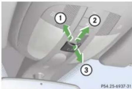
text_image
① ② ③ P54.25-6937-31Sunroof switch
① Raising
② Opening
③ Closing
With the sunroof closed or raised, you can slide the sunroof screen forward and back.
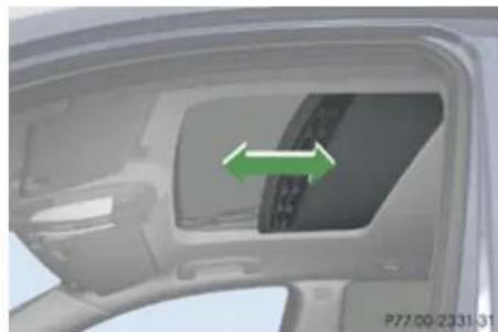
natural_image
Interior view of a car showing the door, dashboard, and side panel with a green arrow indicating direction (no text or symbols)Sunroof screen
▶ Switch on the ignition.
Opening
▶ Opening manually: Press and hold the sunroof switch to the resistance point in direction of arrow ②.
▶ Release the sunroof switch when the desired position is reached.
▶ Express operation: To open the tilt/sliding sunroof completely, press the sunroof switch past the resistance point in direction of arrow ② and release.
▶ Stopping during express operation: Move the sunroof switch in any direction.
When the tilt/sliding sunroof is open, resonance noises may result in addition to the usual wind noises. They are caused by minimal pressure changes in the passenger compartment. To reduce or eliminate these noises, change the position of the tilt/sliding sunroof or open a window slightly.
Controls in detail
Power tilt/sliding sunroof
Raising
▶ Rasing manually: Press and hold the sunroof switch to the resistance point in direction of arrow ①.
▶ Release the sunroof switch when the desired position is reached.
Express operation: To raise the tilt/sliding sunroof completely, press the sunroof switch past the resistance point in direction of arrow ① and release.
▶ Stopping during express operation: Move the sunroof switch in any direction.
Closing
▶ Closing manually: Pull and hold the sunroof switch to the resistance point in direction of arrow ③.
▶ Release the sunroof switch when the desired position is reached.
Express operation: To close the tilt/sliding sunroof completely, pull the sunroof switch past the resistance point in direction of arrow ③ and release.
▶ Stopping during express operation: Move the sunroof switch in any direction.
Closing when the tilt/sliding sunroof is blocked
Warning!
Make sure that nobody can become trapped and be seriously or even fatally injured when closing the tilt/sliding sunroof with greater force or without automatic reversal function.
If the movement of the tilt/sliding sunroof is blocked during the closing procedure, the tilt/sliding sunroof will stop and open slightly. However, the tilt/sliding sunroof will exert greater force before reversing than when the tilt/sliding sunroof is closed in express operation. Please exercise caution!
▶ Immediately after the tilt/sliding sunroof has stopped because it was blocked, pull the sunroof switch in direction of arrow ③ (▷ page 225) until the tilt/sliding sunroof is fully closed.
If the tilt/sliding sunroof is blocked again and opens slightly:
▶ Immediately after the tilt/sliding sunroof was blocked, pull the sunroof switch in direction of arrow ③ until the tilt/sliding sunroof is fully closed.
Warning!
Pulling and holding the sunroof switch to close the tilt/sliding sunroof immediately after it had been blocked two times will cause the tilt/sliding sunroof to close without any reversal function for as long as you hold the sunroof switch.
Synchronizing
The tilt/sliding sunroof must be synchronized
• after the battery has been disconnected or discharged
• after a malfunction
- if the tilt/sliding sunroof does not open smoothly
! If the tilt/sliding sunroof cannot be closed or synchronized, contact an authorized Mercedes-Benz Center or call Roadside Assistance.
▶ Vehicles with SmartKey: Switch off the ignition and remove the SmartKey from the starter switch.
▶ Vehicles with KEYLESS-GO: Switch off the ignition and open the driver's door (this puts the starter switch in position 0, same
as with the SmartKey removed from the starter switch). The driver's door then can be closed again.
Remove the fuse for the tilt/sliding sunroof from the fuse box (▷ page 415).
▶ Reinsert the fuse in the fuse box.
▶ Switch on the ignition.
▶ Press and hold the sunroof switch in direction of arrow ① (▷ page 225) until the tilt/sliding sunroof is fully raised at the rear.
- Keep holding the sunroof switch in direction of arrow ① for approximately 1 second.
▶ Check the express operation feature (> page 225).
If the tilt/sliding sunroof opens and closes completely, the roof is synchronized.
Otherwise repeat the above steps.
Loading and storing
Loading instructions
Warning!
Always fasten items being carried as securely as possible using cargo tie-down rings and fastening materials appropriate for the weight and size of the load. In an accident, during hard braking or sudden maneuvers, loose items will be thrown around inside the vehicle and can cause injury to vehicle occupants unless the items are securely fastened in the vehicle.
To help avoid personal injury during a collision or sudden maneuver, exercise care when transporting cargo. Do not pile luggage or cargo higher than the seat backrests.
The cargo compartment is the preferred place to carry objects. Always use cargo tie-down rings, and if so equipped, always use the cargo net when transporting cargo. Never drive vehicle with the tailgate open. Deadly carbon monoxide (CO) gases may enter vehicle interior resulting in unconsciousness and death.
Load distribution
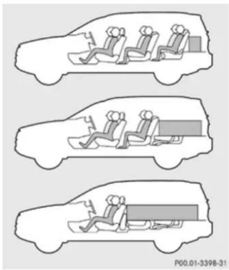
natural_image
Three-panel diagram showing a car interior with three different scenarios of seating and mobility, no text or symbols present.The Gross Vehicle Weight (GVW) which is the weight of the vehicle including fuel, tools, spare wheel, installed accessories, passengers and luggage/cargo must never exceed the load limit and the Gross Vehicle Weight Rating (GVWR) for your vehicle as specified on the placard located on the driver's door B-pillar (▷ page 275).
In addition, the load must be distributed in such a way so that the weight on each axle
▶▶
Controls in detail
Loading and storing
never exceeds the Gross Axle Weight Rating (GAWR) for the front and rear axle. The GVWR and GAWR for your vehicle are indicated on the certification label located on the driver's door B-pillar ( page 275).
For more information, see "Tire and Loading Information" ( page 275).
The handling characteristics of a fully loaded vehicle depend greatly on the load distribution. It is therefore recommended to load the vehicle according to the illustration shown, with the heaviest items being placed towards the front of the vehicle.
Please pay attention to and comply with the following instructions when loading the vehicle and transporting cargo:
• Always place items being carried against front or rear seat backrests, and fasten them as securely as possible.
- The heaviest portion of the cargo should always be kept as low as possible against front or rear seat backrests.
For additional safety when transporting cargo while the rear seats are unoccupied, fasten the outer seat belts crosswise into the opposite side buckles.
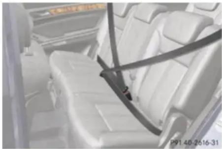
natural_image
Interior view of a car showing white rear seats with a black seatbelt (no visible text or symbols)The cargo compartment is the preferred place to carry objects. The expanded cargo volume (▷ page 235) should only be used for items which do not fit in the cargo compartment alone.
Carriers
For information about further carriers, contact an authorized Mercedes-Benz Center.
Warning!
Only use carriers when the crossbars have been completely mounted. The left and right roof rails are only stabilized by means of the crossbars mounted.
Follow the manufacturer's installation instructions. Otherwise, an improperly attached carrier or its load could become detached from the vehicle.
Do not exceed the maximum roof load of 198 lb (90 kg).
Take into consideration that when the roof is loaded, the handling characteristics are different from those when operating the vehicles without a roof loaded.
Make sure
- you can open the tailgate completely
- you can raise the tilt/sliding sunroof at the rear completely
Controls in detail
Loading and storing
i The following accessories are available for your Mercedes-Benz:
- Roof Cargo Container – Small, Medium, or Large
- Ski and Snowboard Carrier – Standard
- Ski and Snowboard Carrier – Deluxe (Only in connection with corresponding adapter.)
For more information on Mercedes-Benz accessories, contact your authorized Mercedes-Benz Center.
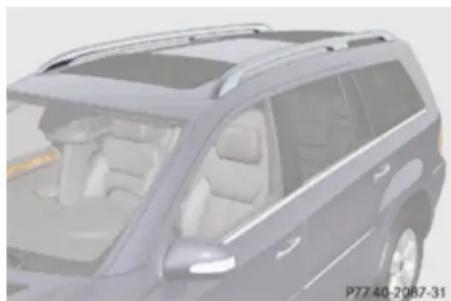
natural_image
Exterior view of a modern SUV (no visible text or symbols)Roof rails
Crossbars
The maximum roof load of any add-on roof equipment is reduced by the unladen weight of the crossbars (13.7 lbs/6.2 kg).
Four keys and an Allen wrench required for installing and removing are included with the crossbars.
The keys and the Allen wrench are stored with the vehicle tool kit under the cargo compartment floor ( page 326).
i Spare parts are available as Mercedes-Benz accessories. Contact your authorized Mercedes-Benz Center.
Installing the crossbars
Warning!
Please follow these installation instructions carefully. Caution should be exercised to avoid damage to the vehicle while installing the crossbars. Also, be careful not to injure yourself or others while installing and adjusting the crossbars or loading items on them.
Each individual step of the installation instructions, the warning notices, the general safety precautions and the
instructions for use must be followed exactly. If the crossbars are not mounted correctly, they and the objects attached to them could come loose from your vehicle and cause an accident, thereby injuring you and other persons and/or causing damage to property, including damage to your vehicle.
Warning!
Every time the crossbars are mounted, before you set off on a journey and periodically during longer journeys, check all the screws on the crossbars to make sure that they are secure, and tighten them if necessary. Repeat these checks at regular intervals as road-surface conditions dictate, and at least after every 1500 miles (2500 km) of continuous use.
Otherwise, the crossbars, mounted accessories and the objects attached to them could come loose from the vehicle causing an accident, thereby injuring you and other persons and/or causing damage to property, including damage to your vehicle.
Do not use lubricant on the screws of the crossbars. The screws could work loose and the crossbars could become detached
Controls in detail
Loading and storing
from your vehicle, together with the objects attached to them causing an accident, thereby injuring you and other persons and/or causing damage to property, including damage to your vehicle.

Warning!
Only install the crossbars at the exact locations designated on the roof rails. The designated locations for the front crossbars are between the markings engraved on the inside of the roof rails. The designated locations for the rear crossbars are between the gaps on the roof rails. Otherwise, the crossbars, mounted accessories and the objects attached to them could come loose from the vehicle causing an accident, thereby injuring you and other persons and/or causing damage to property, including damage to your vehicle.

Warning!
A roof load creates a greater surface area exposed to the wind and causes the vehicle to have a higher center of gravity, thereby changing the vehicle's driving characteristics. Accordingly, the additional weight on the roof of the vehicle can have
a detrimental effect on braking, cornering and acceleration.
Never exceed the maximum permissible roof load or the maximum permissible vehicle weight, even when accessories for the crossbars (e.g. ski racks, bicycle racks, etc.) are being used. Overloading the vehicle could result in an accident. When calculating the weight placed on the roof please make sure to add the weight of the crossbars, accessory racks and the load carried together.
Always adapt your driving style to the road, traffic and weather conditions, and drive with added caution when the roof is loaded. Always drive with extreme care when the carrier is loaded. Take into consideration that when the carrier is loaded, the handling characteristics are different from those when operating the vehicle without a carrier loaded.

Warning!
Do not use accessories which have not been approved by Mercedes-Benz for use in conjunction with these crossbars. If non-approved accessories are used, these accessories and/or the objects attached to
them could come loose from the vehicle, thereby injuring you and other persons and/or causing damage to property, including damage to your vehicle.

Have a second person assist you when installing the crossbars. The vehicle could otherwise be damaged.

Objects attached to the crossbar system's accessories must not be allowed to restrict the movement of the tilt/sliding sunroof. The tilt/sliding sunroof could otherwise be damaged when it is raised.
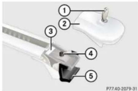
text_image
① ② ③ ④ ⑤ P77.40-2079-31① Key
② Cover cap
③ Sticker FRONT (or REAR)
Controls in detail
Loading and storing
④ Screw for clamping claw
⑤ Clamping claw
The front and rear crossbars are of different lengths. Please pay close attention to stickers ③ FRONT and REAR on the crossbars.
▶ Unlock cover cap ② with key ①.
Remove cover cap ②.
Sticker ③ indicating the location, FRONT or REAR, becomes visible.
▶ Turn screw ④ counterclockwise with the included Allen wrench until clamping claw ⑤ is wide open.
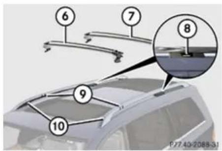
text_image
6 7 8 9 10 P 77 40-2088-31⑥ Front crossbar
⑦ Rear crossbar
⑧ Gaps
⑨ Markings
⑩ Roof rails
▶ Place front crossbar ⑥ between markings ⑨ on roof rails ⑩.
i Markings ⑨ are located on the inside of each roof rail, indicated by the white lines in the illustration.
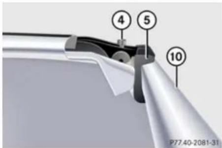
text_image
4 5 10 P77.40-2081-31④ Screw for clamping claw
⑤ Clamping claw
⑩ Roof rail
▶ Make sure clamping claw ⑤ lies flush against the inside of roof rail ⑩ as shown in the illustration.
If necessary, adjust clamping width of crossbar (▶ page 232).
▶ Slightly tighten screw ④ on both sides by turning it clockwise.
▶ Place rear crossbar ⑦ on roof rails ⑩ in such a way that the clamping claws reach into gaps ⑧ (▶ page 231) on the roof rails.
▶ Make sure clamping claw ⑤ lies flush against the inside of roof rail ⑩ as shown in the illustration (▷ page 231).
If necessary, adjust clamping width of crossbar (▷ page 232).
▶ Slightly tighten screw ④ on both sides by turning it clockwise.
On the front and rear crossbars tighten screws ④. Observe a tightening torque of 4 lb-ft (6 Nm).
Warning!
Have the tightening torque checked after mounting the crossbars. The screws could come loose if they are not tightened to a torque of 4 lb-ft (6 Nm).
Controls in detail
Loading and storing
▶ Attach cover caps (▷ page 230) and lock them.
▶ Store key and Allen wrench back into the storage well (▷ page 326).
Adjusting the clamping widths of the crossbars
Warning!
Only install the crossbars at the exact locations designated on the roof rails. The designated locations for the front crossbars are between the markings engraved on the inside of the roof rails. The designated locations for the rear crossbars are between the gaps on the roof rails. Otherwise, the crossbars, mounted accessories and the objects attached to them could come loose from the vehicle causing an accident, thereby injuring you and other persons and/or causing damage to property, including damage to your vehicle.
The clamping widths of the crossbars are factory set for your vehicle. These clamping widths are solely intended for the designated positions.
Only install the crossbars at the designated locations and pay attention to the stickers ③ FRONT and REAR (▷ page 231).
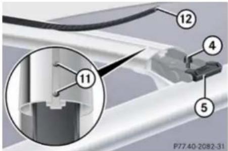
text_image
12 4 11 5 P77.40-2082-31④ Screw for clamping claw
⑤ Clamping claw
⑪ Screws for adjusting clamping width (2 in total for each side)
⑫ Cover strip
▶ Pull cover strip ⑫ out of groove until you see screws ⑪ on each end of the crossbar.
▶ Turn screws ⑪ on both sides counterclockwise approximately 2 rotations.
▶ Place the crossbar at designated locations (▷ page 231) on roof rails.
On both sides, make sure the clamping claws ⑤ lie flush against the roof rails. If necessary, pull out or push in the clamping claws ⑤.
▶ Tighten screws ⑪. Observe a tightening torque of 4 lb-ft (6 Nm).
The width of the clamping claws is correctly adjusted.
Warning!
Have the tightening torque checked after mounting the crossbars. The screws could come loose if they are not tightened to a torque of 4 lb-ft (6 Nm).
▶ Press cover strip ⑫ piece by piece into groove of crossbar.
▶ Install the crossbars as described (▷ page 229).
Removing the crossbars
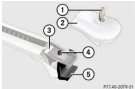
text_image
① ② ③ ④ ⑤ P77.40-2079-31① Key
② Cover cap
③ Sticker FRONT (or REAR)
④ Screw for clamping claw
⑤ Clamping claw
▶ Unlock cover cap ② with key ①.
▶ Remove cover cap ②.
▶ Turn screws for clamping claws ⑤ counterclockwise until the crossbars can be lifted from the roof rails.
Shortening the cover strip
The cover strips reduce the wind noise caused by the crossbars. In order to install add-on roof equipment, it may be necessary to shorten the cover strips.
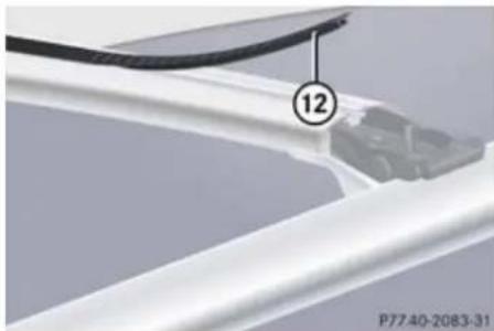
natural_image
Close-up of a white plastic component with a black cable and numbered annotation (12), no readable text or symbols beyond the number and date.⑫ Cover strip
▶ Pull cover strip ⑫ out of groove.
▶ Attach add-on roof equipment to the crossbars.
Place cover strip ⑫ flush against the add-on roof equipment, and mark the end of crossbar on cover strip.
▶ Cut off cover strip ⑫ at marked location.
▶ Press cover strip ⑫ piece by piece into groove of the crossbar.
i Cover strips are available as Mercedes-Benz accessories. Contact your Mercedes-Benz Center.
Parcel nets
Warning!
USA only:
Do not place objects with a combined weight of more than 4.4 lbs (2 kg) into the parcel net on the back of the front passenger seat. Otherwise, the Occupant Classification System OCS may not be able to properly approximate the occupant weight category.
Warning!
The parcel net is intended for storing lightweight items only, such as road maps, mail, etc.
Heavy objects, objects with sharp edges or fragile objects may not be transported in the parcel net. In an accident, during hard braking, or sudden maneuvers, they could be thrown around inside the vehicle and cause injury to vehicle occupants.
The parcel net cannot protect transported goods in the event of an accident.
Parcel nets are located in the front passenger footwell and on each of the front seat backrests.
Controls in detail
Loading and storing
Cargo tie-down rings
Your vehicle is equipped with eight cargo tie-down rings.
Carefully secure cargo by applying even load on all rings with rope of sufficient strength to hold down the cargo.
Always follow loading instructions (▷ page 227).
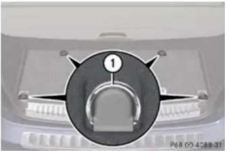
natural_image
Close-up of a mechanical component with a circular dial and central knob, no visible text or symbolsCargo compartment
① Cargo tie-down ring
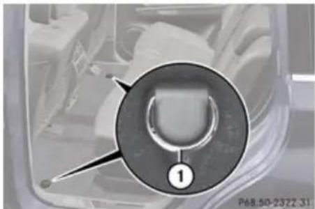
natural_image
Close-up of a car interior component with a circular dial and numbered marker (1), no readable text or symbols present.Second-row footwell
① Cargo tie-down ring
The maximum permissible weight per cargo tie-down ring is 331 lb (150 kg).
For Information on how to fold the third-row seats, see "Expanding cargo volume" (▷ page 235).
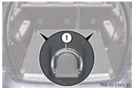
natural_image
Top-down view of a car trunk with a circular inset highlighting a key component labeled '1' (no text or symbols on the main body)Third-row seat backrest
① Cargo tie-down ring
Hooks
Two hooks are located on the rear compartment trim panels, one on each side.
Controls in detail
Loading and storing
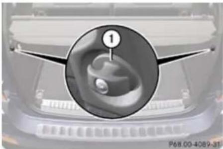
natural_image
Close-up of a car's front grille with a magnified inset showing a finger contact detail (no text or symbols)① Hook
Use the hooks to secure light-weight items only. The maximum permissible weight per hook is 9 lbs (4 kg).
Expanding cargo volume
You can separately fold the left and right rear seat backrests to expand the cargo volume.

Warning!
When expanding the cargo volume, always fully fold the corresponding seats and, if so equipped, always use the cargo net when transporting cargo.
Unless you are transporting cargo, the seat backrests must remain properly locked in the upright position.
In an accident, during hard braking or sudden maneuvers, loose items will be thrown around inside the vehicle, and can cause injury to vehicle occupants unless the items are securely fastened in the vehicle.
Always use the cargo tie-down rings.
Warning!
Never drive the vehicle with the tailgate open. Deadly carbon monoxide (CO) gases may enter vehicle interior resulting in unconsciousness and death.
When the second-row seats are folded forward, the front seats may not be moved to the rearmost position. Otherwise you could damage the front and second-row seats.
Expanding cargo volume in part
Folding third-row seats, electrically
Use the left button, indicated by L, to fold down the left third-row seat. Use the right button, indicated by R, to fold down the right third-row seat.
There are several ways to fold the third-row seats.
Two buttons are located on the right side trim of the third-row seats.
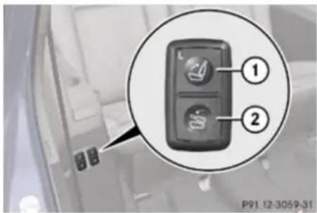
text_image
① ② P91 12-3059-31Example, button for the left third-row seats
① Button for returning third-row seats to upright position
② Button for folding the third-row seats
i It is only possible to fold the third-row seats down when the rear right door is open.
Controls in detail
Loading and storing
Two buttons are located on the passenger-side in the cargo compartment.
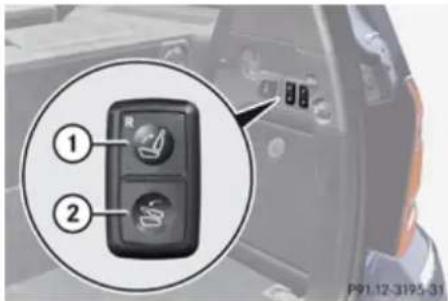
text_image
Camera control panel with labeled buttons and a magnified inset showing two buttons labeled 1 and 2.Example, button for the right third-row seats
① Button for returning third-row seats to upright position
② Button for folding the third-row seats
i It is only possible to fold the third-row seats down when the tailgate is open.
▶ Push in the head restraints of the third-row seats all the way (▷ page 104).
▶ Remove cargo compartment cover blind (▷ page 239).
▶ Press and hold button ② for each side until the third-row seats are fully folded.
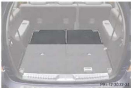
natural_image
Interior view of a car backhaul with two compartments and battery cover (no visible text or symbols)If a third-row seat is not engaged properly, for example, the message 3rd Row Of Seats-Right Not Locked appears in the multifunction display (▷ page 148).
▶ Press and hold button ② again, until the message disappears.
Expanding cargo volume fully
Warning!
Folded second-row seats are intended to serve as a cargo volume expansion in conjunction with folded third-row seats only. Do not fold the second-row seats and allow third-row seat occupants to use folded second-row seats as a footrest while driving. Third-row seat occupants must, like all vehicle occupants, keep both feet on the
floor in front of their seat. Otherwise, occupants could slide under their seat belt in a collision. If occupants slide under the seat belt, it would apply force at the abdomen or neck. That could cause serious or even fatal injuries. Do not fold the second-row seats and allow third-row seat occupants to use folded second-row seats as a table while driving. Objects placed on folded second-row seats may come loose during braking, vehicle maneuvers, or an accident and be thrown around the vehicle interior. Objects thrown around the vehicle interior may cause an accident and/or serious personal injury.
Folding second-row seats
! When the second-row seats are folded forward, the front seats may not be moved to the rearmost position. Otherwise you could damage the front and second-row seats.
▶ Push in the head restraints of the second-row seats all the way (▷ page 104).
Controls in detail
Loading and storing
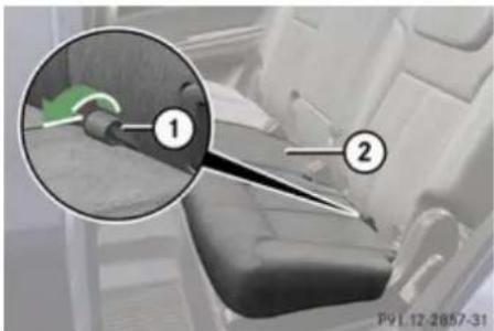
natural_image
Interior view of a car seatbelt with a magnified inset showing a component (no text or symbols visible)① Strap
② Seat cushion
▶ Pull strap ① in direction of arrow.
▶ Fold seat cushion ② forward.
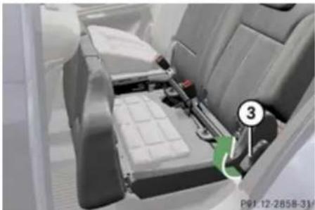
natural_image
Interior view of a car showing the dashboard and seat area with a numbered component (no visible text or symbols)③ Lever
▶ Pull and hold lever ③ in direction of arrow at resistance point.
The seat backrest folds down.
▶ Check for secure locking by pushing and pulling on the seat backrest.
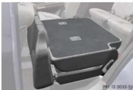
natural_image
Close-up of a black plastic car seat with visible mounting brackets and side panels (no text or symbols)Folding third-row seats, electrically
Use the left button, indicated by L, to fold down the left third-row seat.
Use the right button, indicated by R, to fold down the right third-row seat.
There are several ways to fold the third-row seats.
Two buttons are located on the right side trim of the third-row seats.
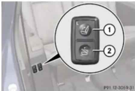
text_image
① ② P91.12-3059-31Example, button for the left third-row seats
① Button for returning third-row seats to upright position
② Button for folding the third-row seats
i It is only possible to fold the third-row seats down when the rear right door is open.
Controls in detail
Loading and storing
Two buttons are located on the passenger-side in the cargo compartment.
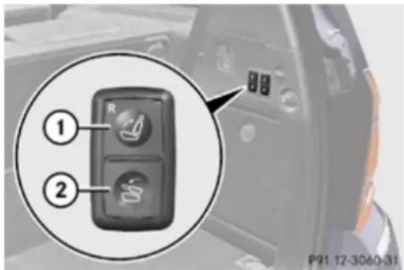
text_image
① ②Example, button for the right third-row seats
① Button for returning third-row seats to upright position
② Button for folding the third-row seats
▶ Push in the head restraints of the third-row seats all the way (▷ page 104).
i It is only possible to fold the third-row seats down when the tailgate is open.
▶ Remove cargo compartment cover blind (▷ page 239).
▶ Press and hold button ② for each side until the third-row seats are fully folded.
The cargo compartment is fully extended.
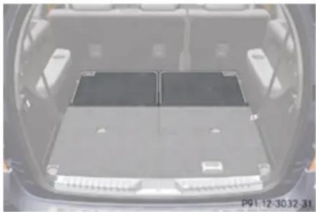
natural_image
Interior view of a car trunk with two rectangular battery compartments (no visible text or symbols)If a third-row seat is not engaged properly, for example, the message 3rd Row Of Seats-Right Not Locked appears in the multifunction display (▷ page 148).
▶ Press and hold button ② again, until the message disappears.
Returning seats to their original position
Warning!
Make sure all seats are properly locked in position before driving off. Do not drive with seats not properly locked.
Never ride in a moving vehicle with the seat not properly locked as this can be dangerous. The seat could move forward and the seat backrest could fold. You could slide under the seat belt during braking,
vehicle maneuvers, or in an accident. If you slide under it, the seat belt would apply force at the abdomen or neck. That could cause serious or even fatal injuries. Never ride in a moving vehicle with the seat not properly locked as this can be dangerous. The seat could move forward and the seat backrest could fold. You could slide under the seat belt during braking, vehicle maneuvers, or in an accident. If you slide under it, the seat belt would apply force at the abdomen or neck. That could cause serious or even fatal injuries.
The seat backrest and seat belt provide the best restraint when the wearer is in a nearly upright position and the seat belt is properly positioned on the body.
Step 1:
▶ Return third-row seats to its original position (▷ page 236).
Controls in detail
Loading and storing
Step 2:
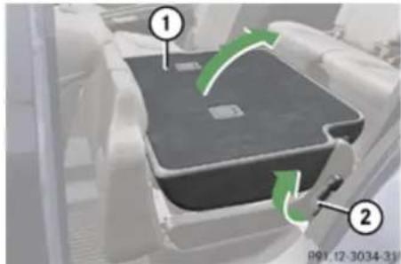
natural_image
3D diagram of a mechanical component with green arrows indicating motion or flow, no readable text or symbols present.① Seat backrest
② Lever
▶ Pull and hold lever ② in direction of arrow at resistance point.
▶ Fold seat backrest ① rearward until it engages.
▶ Check for secure locking by pushing and pulling on seat backrest ①.
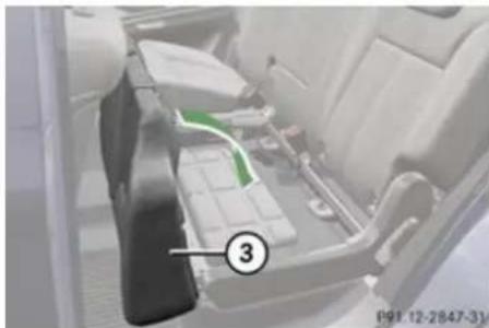
natural_image
Interior view of a vehicle battery pack with labeled component (3), no visible text or symbols beyond the number and date③ Seat cushion
▶ Fold seat cushion ③ rearward until it locks into position.
Cargo compartment cover blind
The cargo compartment cover blind can be installed behind the third-row seats or the second-row seats.
! With the cargo compartment cover blind installed, do not pile luggage higher than the lower edges of the rear side windows.
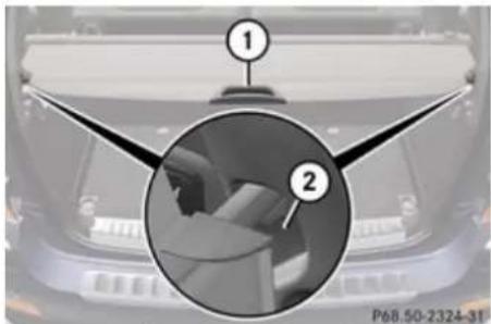
text_image
① ② P68.50-2324-31Blind installed behind third-row seats
① Handle
② Mount
▶ Rolling out blind: Pull blind on handle ① across the cargo compartment.
▶ Guide blind into mounts ② and release.
▶ Rolling up blind: Disengage blind and guide retraction by its handle ①.
Removing and installing blind
Before removing or installing cargo compartment cover blind behind the third-row seats, fold the left or right third-row seat forward (▷ page 235). Afterwards, return the left or right third-row seat into its original position.
▶▶
Controls in detail
Loading and storing
Before installing cargo compartment cover blind behind the second-row seats, fold the third-row seats forward (▷ page 235).
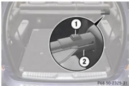
natural_image
Close-up of a car engine compartment with a magnified inset showing internal components (no text or symbols visible)Blind installed behind second-row seats
① Release button
② Blind
▶ Removing: Pull blind ② to the left until it engages.
Installing: Remove the mount covers in the side trims of the third seat row when installing roller blind ② behind the second-row seats.
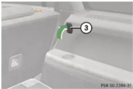
text_image
P68.50-2386-31Mount cover behind second-row seats
③ Cover
- Press on cover ③ at its upper edge as indicated by arrow.
The cover's lower edge flips up.
▶ Remove cover ③ by pulling its lower edge out of the side trim.
To avoid loss of the covers, insert the covers into the mounts currently not in use.
▶ Make sure release button ① faces up and the roller blind handle (▷ page 239) is to the rear before inserting the roller blind.
▶ Place left side of blind ② in left mount.
▶ Position right side of blind ② over right mount.
▶ Press release button ① and guide blind ② into mount.
▶ Make sure the cargo compartment cover blind is securely fastened.
Cargo net
Warning!
Make sure the cargo net is properly engaged at top and bottom position and the tightening belts are securely fastened.
Never use a damaged cargo net.
To help avoid personal injury from smaller objects being thrown around in the occupant compartment during a collision or sudden maneuver, always use cargo net when transporting cargo.
The cargo net cannot prevent the movement of large, heavier objects into the passenger compartment in an accident.
Such items must be properly secured using the cargo tie-down rings in the cargo compartment floor.
Passenger use of seats behind installed cargo net is restricted because of the footwell being taken up by the net.
Controls in detail
Loading and storing
Use of the cargo net is a particularly important safety factor when the vehicle is loaded higher than the top of the seat backrests with smaller objects. For your safety, always use the cargo net when transporting cargo.
The cargo net can be installed in two locations:
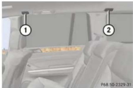
natural_image
Interior view of a car showing two numbered compartments (1 and 2) with hands holding the backrest area (no visible text or symbols)① Holder behind B-Pillar
② Holder behind C-Pillar
- With the cargo volume expanded in part ( page 235), use holders behind C-pillars ② and the cargo tie-down rings behind the third-row seat backrest ( page 234).
- With the cargo volume fully expanded ( page 236), use holders behind B-pillars ① and the cargo tie-down rings in the second-row footwell ( page 234).
▶ Open the hook and loop fasteners on the cargo net package.
▶ Roll out the cargo net.
▶ Unfold the cargo net.
▶ Engage the lower cargo net bar.
The cargo net bar must engage audibly.
Installing the cargo net
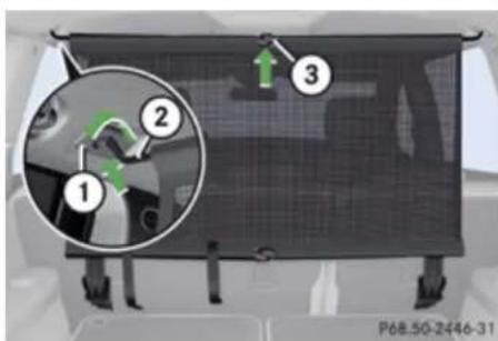
text_image
1 2 3 P68.50-2446-31Cargo net installed behind the C-pillar
① Holder
② Cargo net bar
③ Cargo net bar
▶ Hang cargo net bar ② on holder ① as indicated by the arrow.
▶ Push cargo net bar ② forward into holder ① in direction of arrow.
▶ Engage cargo net bar ③.
The cargo net bar must engage audibly.
Pulling the cargo net tight
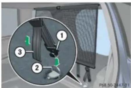
text_image
Diagram showing a car interior with numbered parts and a magnified inset highlighting a specific area, likely for safety or safety inspection.Belt hook attached behind the third-row seat backrest
① Belt hook
② Cargo tie-down ring
③ Tightening belt
Controls in detail
Loading and storing
▶ Hook belt hook ① into cargo tie-down ring ② in direction of arrow.
▶ Pull tightening belt ③ by the loose end in direction of arrow until the cargo net is pulled tight.
▶ After driving a short distance, make sure the cargo net is still tight and, if necessary, pull it tight again.
Loosening the cargo net
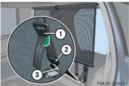
text_image
1 2 3 P68.50-2448-31Belt hook attached behind the third-row seat backrest
① Buckle
② Belt hook
③ Cargo tie-down ring
▶ Loosen the tightening belt by pulling buckle ① upward in direction of arrow.
Remove belt hook ② from cargo tie-down ring ③.
Removing and storing the cargo net
▶ Take cargo net bar ② out of holder ① (▷ page 241).
▶ Press the red button on the upper and lower cargo net bar.
▶ Fold the cargo net.
▶ Roll up the cargo net.
▶ Close the hook and loop fasteners on the cargo net package.
Storage compartments
Warning!
To help avoid personal injury during a collision or sudden maneuver, exercise care when storing objects in the vehicle. Put luggage or cargo in the cargo compartment if possible. Do not pile luggage or cargo higher than the seat backrests.
If so equipped, always use the cargo net when transporting cargo. The cargo net cannot secure hard or heavy objects.
Parcel nets cannot secure hard or heavy objects.
Keep compartment lids closed. This will help to prevent stored objects from being thrown about and injuring vehicle occupants during
- braking
- vehicle maneuvers
- an accident
Glove box
Depending on vehicle equipment, an AUX socket or a media interface are located in the glove box. For information on Audio AUX
Controls in detail
Loading and storing
mode or on media interface, see separate COMAND system operating instructions.
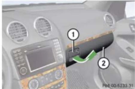
text_image
Car infotainment panel with numbered labels pointing to a device, showing a green arrow indicating direction.① Glove box lid release
② Glove box lid
▶ Opening: Pull glove box lid release ①.
▶ Closing: Push glove box lid ② up until it engages.
Locking and unlocking the glove box separately
You can lock the glove box separately, e.g. when the vehicle is in the shop for service.
The glove box can only be locked or unlocked with the mechanical key.
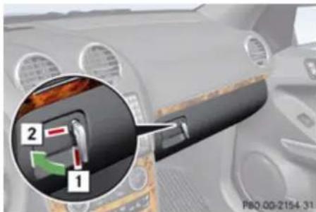
text_image
Car interior diagram showing a car's seatbelt switch with labeled parts and a magnified inset highlighting the component '2'.1 Unlocking glove box
2 Locking glove box
Storage compartment in front center console
Depending on vehicle equipment, your vehicle may not be equipped with both storage compartments.
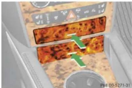
natural_image
Close-up of a device's front panel showing a textured orange surface with a green arrow indicating a specific area, no visible text or symbols.In vehicles with enhanced off-road package, the upper storage compartment contains a control panel (▷ page 144) or (▷ page 189).
▶ Briefly press the front of the cover. The cover opens automatically.
Controls in detail
Loading and storing
Front armrest storage compartment
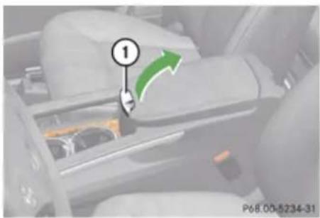
text_image
① P68.00-5234-31① Button to open storage compartment
i The Roadside Assistance button (▷ page 253) and the Information button (▷ page 254) are located in the storage compartment.
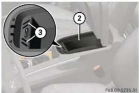
text_image
3 2 P68.00-5235-31② Storage compartment
③ Coin holder
▶ Opening storage compartment: Pull button ① and lift up armrest.
Coin holders ③ are located in front of storage compartment ②.
Rear storage compartments
Depending on vehicle equipment, your vehicle may not be equipped with three storage compartments in the front of the rear seats.
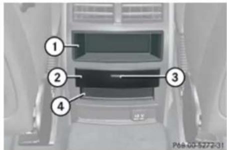
text_image
Diagram of a car interior showing labeled compartments or slots, with numbered annotations pointing to specific areas.① Storage compartment
② Storage compartment cover
③ Release button
④ Storage compartment
▶ Briefly press release button ③ on storage compartment cover ②.
The storage compartment opens automatically.
Controls in detail
Useful features
Useful features
Cup holders

Warning!
In order to help prevent spilling liquids on vehicle occupants and/or vehicle equipment, only use containers that fit into the cup holder. Use lids on open containers and do not fill containers to a height where the contents, especially hot liquids, could spill during braking, vehicle maneuvers, or in an accident. Liquids spilled on vehicle occupants may cause serious personal injury. Liquids spilled on vehicle equipment may cause damage not covered by the Mercedes-Benz Limited Warranty.
When not in use, keep the cup holder closed. An open cup holder may cause injury to you or others when contacted during braking, vehicle maneuvers, or in an accident.
Keep in mind that objects placed in the cup holder may come loose during braking, vehicle maneuvers, or in an accident and be thrown around in the vehicle interior. Objects thrown around in the vehicle interior may cause an accident and/or serious personal injury.
Cup holder in front center console
A cup holder and a card/ticket holder are located in the front center console.
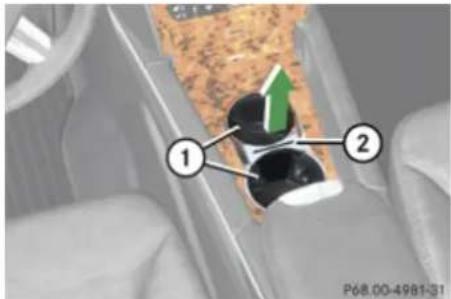
text_image
① ② P68.00-4981-31① Cup holder
② Bridge with card, ticket holder
The front cup holder can be removed for cleaning purposes.
Removing: Hold cup holder at its bridge ② and pull out bridge in direction of arrow.
▶ Pull cup holder ① out in direction of arrow.
▶ Reinstalling: First, insert cup holder ① and then insert bridge ②.
Cup holder in rear armrest
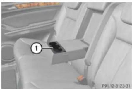
natural_image
Interior view of a car showing the rearrest seat and armrest (no visible text or symbols)① Cup holder
▶ Pull the armrest down by its top.
! Do not sit on or lean your body weight against the armrest when it is folded down, as you could otherwise damage it.
Cup holder in third-row side trim
Cup holder are located in the side trims of the third-row seats.
Controls in detail
Useful features
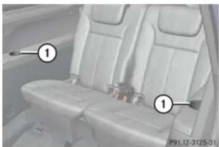
natural_image
Interior view of a car showing two seats with seatbelt covers, labeled with numbers 1 and P91.12-3125-31 (no text or symbols beyond labels)① Cup holder
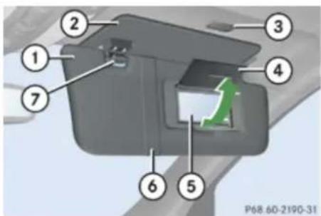
text_image
Technical diagram of a mechanical component with numbered parts and a green directional arrow indicating motion or movement.① Sun visor
② Additional sun visor
③ Vanity mirror lamp
④ Vanity mirror cover
⑤ Vanity mirror
⑥ Holder, e.g. for gas cards
⑦ Mounting
Sun visors
Warning!
Do not use the vanity mirror while driving. Keep the vanity mirrors in the sun visors closed while vehicle is in motion. Reflected glare can endanger you and others.
Glare through the windshield
▶ Flip sun visor ① down when you experience glare.
Glare through a door window
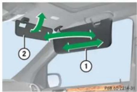
text_image
P68 00 2214-31① Sun visor
② Additional sun visor
▶ Close vanity mirror cover ④ if opened.
▶ Disengage sun visor ① from mounting ⑦.
▶ Pivot sun visor ① to the side.
Adjust sun visor ① by pushing or pulling in direction of arrows.
▶ Flip down additional sun visor ② when you experience additional glare through the windshield.
Vanity mirror
The mirror lamp only functions when the sun visor is engaged in mounting.
▶ Flip sun visor ① down.
▶ Lift up vanity mirror cover ④.
Vanity mirror lamp ③ comes on.
Rear panorama roof sunshade
The rear panorama roof sunshade over the third-row seats prevents the sun from shining directly into the vehicle.
You can open and close the sunshade by hand.
! Always guide the sunshade. Do not let it snap back abruptly, as it could be damaged.
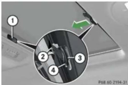
text_image
1 2 3 4 P68 60-2194-31① Mounting
② Clip
③ Handle
④ Button
▶ Extending: Grasp on handle ③ and insert clips ② into mounting ①.
The third-row sunshade engages.
▶ Retracting: Press on button ④ to disengage the third-row sunshade from mounting ①.
Ashtrays
Center console ashtray
Warning!
Remove front ashtray insert only with vehicle standing still.
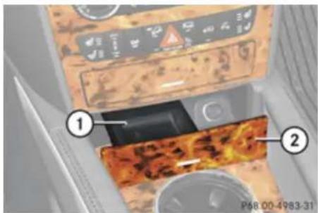
text_image
Diagram showing a device with labeled parts, including a control panel and a textured surface with annotations.① Ashtray insert
② Cover
▶ Opening: Briefly press cover ②.
Removing ashtray insert: Grab ashtray insert ① on the sides and pull it out upwards.
Controls in detail
Useful features
▶ Reinstalling ashtray insert: Install ashtray insert ①.
▶ Closing: Push cover ②.
Rear center console ashtray
! Close the ashtray when not in use and before folding the second-row seats. Otherwise you could damage the ashtray.

text_image
① ② P68.00-4984-31① Ashtray insert
② Cover
▶ Opening: Briefly press cover ②.
Removing ashtray insert: Grab ashtray insert ① on the sides and pull it out upwards.
▶ Reinstalling ashtray insert: Install ashtray insert ①.
▶ Closing: Push cover ②.
Cigarette lighter
⚠️ Observe Safety notes, see page 68.
Warning!
Never touch the heating element or sides of the lighter; they are extremely hot. Hold the knob only.
Make sure any children traveling with you do not injure themselves or start a fire with the hot cigarette lighter.
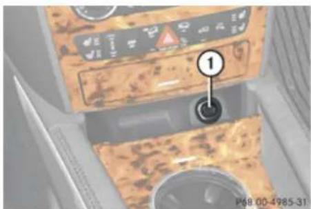
text_image
① P68 00-4985-31① Cigarette lighter
▶ Open the ashtray (▷ page 247).
▶ Switch on the ignition.
▶ Push in cigarette lighter ①.
Cigarette lighter ① will pop out automatically when hot.
▶ Take out cigarette lighter ①.
▶ Reinsert cigarette lighter ① in its socket after use.
! The lighter socket can be used to accommodate 12V DC electrical accessories (up to a maximum of 180 W) designed for use with the standard "cigarette lighter" plug type. Keep in mind, however, that connecting accessories to the lighter socket (for example extensive connecting and disconnecting, or using plugs that do not fit properly) can damage the lighter socket. With the socket damaged, the lighter may not function properly any longer.
! The cigarette lighter is not designed for use with the electric air pump. Use the power outlet in the second-row footwell for electric air pump operation.
Controls in detail
Useful features
If the engine is off and the cigarette lighter is being used extensively, the vehicle battery may become discharged.
Power outlets
You can use the power outlets even if the ignition is switched off.
An emergency shut-off feature is designed to prevent the vehicle's on-board voltage from dropping below a minimum level. If the on-board voltage drops to this minimum level, the power outlets are automatically switched off, to help preserve engine starting power.
12V Power outlets
! If you use all power outlets in the vehicle, make sure that the maximum current drawn does not exceed 55 A.
! The power outlets in the passenger footwell and cargo compartment are not designed for use with the electric air pump. Use the power outlet in the second-row footwell for electric air pump operation.
The power outlets can be used to accommodate 12V DC electrical accessories
(e.g. mobile phone chargers, auxiliary lamps) up to a maximum of 20 A (240 W).
If the engine is off and the power outlets are being used extensively, the vehicle battery may become discharged.
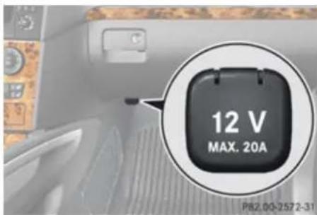
text_image
12 V MAX. 20A P82.03-2572-31Power outlet in front passenger footwell
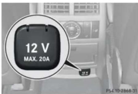
text_image
12 V MAX. 20A P54.10-2868-31Power outlet in second-row footwell
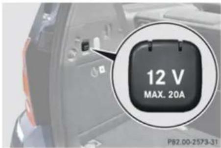
text_image
12 V MAX. 20A P82.00-2573-31Power outlet in cargo compartment
115V AC Socket

Warning!
The 115V AC socket operates at high voltage. Use the 115V AC socket in the vehicle with the same caution and prudence that you exercise when using power outlets at home. Keep any fluids away from the 115V AC socket. Do not clean the socket with fluids or tapered objects. Keep the 115V AC socket cover in the closed position, when not in use. Otherwise, you could suffer an electric shock and be seriously or even fatally injured.
Controls in detail
Useful features

Warning!
A device that you connect must have a suitable plug that complies with U.S. standards. Never pull on the cable to unplug a plug from the 115V AC socket. Do not use a damaged connection cable. The 115V AC socket may not be connected to another 115V AC power source. This could cause serious personal injury to you and/or others.

Warning!
If the 115V AC socket is damaged or torn out of the trim, do not use or touch the 115V AC socket. Using a 115V AC socket that is damaged or torn out of the trim could cause serios personal injury to you and/or others.
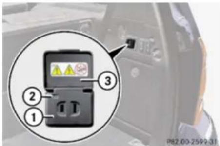
text_image
Diagram of a vehicle electrical switch with labeled components and warning labels① 115V AC socket
② LED
③ Cover
The 115V AC socket provides an alternating current of 115 volts, which enables you to connect small electrical devices with a combined received power of 150 W at most. You can connect small devices such as game consoles, mobile phone chargers, laptops, etc.
Prerequisites for operation:
-
The 12V DC sockets in the rear passenger compartment and cargo compartment are operational.
• The plug of the small device must be inserted fully into the 115V AC socket. -
The on-board voltage of the vehicle is within the permissible voltage range.
- The specified wattage of the small device is identical or lower than the maximum permissible wattage (150 W) of the 115V AC socket.
▶ Operation: Open cover ③.
▶ Insert the plug of the small device into 115V AC socket ①.
LED ② comes on.
If LED ② does not come on, refer to the section on possible nonoperation causes.
▶ Switching off: Pull the plug out of 115V AC socket ①.
Do not pull on the cable.
▶ Close cover ③.
Possible nonoperation causes:
- The on-board voltage of the vehicle is not within the permissible voltage range.
▶ Start the engine. - The temperature of the DC/AC inverter is temporarily too high.
Controls in detail
Useful features
▶ Pull the plug of the small device out of the 115V AC socket and plug it in again after waiting a few minutes.
- Some small devices have a continuous power rating of less than 150 W but a very high switch-on current. Such devices will not operate. When connecting such a device, the socket will not provide power.
If LED ② still does not come on, contact an authorized Mercedes-Benz Center.
Tele Aid
In order to activate the Tele Aid system, a subscriber agreement must be completed. To ensure your system is activated and operational, please press the button to perform the acquaintance call. Failure to complete either of these steps may result in a system that is not activated.
If you have any questions regarding activation, please call the Response Center at 1-800-756-9018 (in the USA) or 1-888-923-8367 (in Canada).
Shortly after the completion of your Tele Aid acquaintance call, you will receive a user ID and password in the mail. You may use this password to access the Tele Aid section in
“Owner’s Online” at mbusa.com (USA only). The “My Tele Aid” section will give you access to account information, remote door unlock and more.
The Tele Aid system is available if
- it has been activated and is operational. Activation requires a subscription for monitoring services, connection and cellular air time.
• vehicle battery power is available - the relevant cellular phone network and GPS signals are available and pass the information on to the Response Center.
i Location of the vehicle on a map is only possible if the vehicle is able to receive signals from the GPS satellite network and pass the information on to the Response Center.
The Tele Aid system
(Telematic Alarm Identification on Demand) The Tele Aid system consists of three types of response:
• Automatic and manual emergency
- Roadside Assistance
• Information
The Tele Aid system is operational providing that the vehicle's battery is charged, properly connected, not damaged, and cellular and GPS coverage is available. The Tele Aid system utilizes the cellular network for communication and the GPS (Global Positioning System) satellites for vehicle location. If either of these signals are unavailable, the Tele Aid system may not function and if this occurs, assistance must be summoned by other means.
To adjust the speaker volume during a Tele Aid call do the following:
▶ Press button + or — on the multifunction steering wheel.
or
▶ Use the adjustment button on your COMAND system.
Controls in detail
Useful features
System self-test
The system performs a self-test after you have switched on the ignition.
Warning!
If the indicator lamps in the SOS button, in the Roadside Assistance button 📋 and/or in the Information button ⚡ do not come on during the system self-test, or if any of these indicators remain illuminated constantly in red and/or the message Tele Aid Inoperative is displayed in the multifunction display after the system self-test, a malfunction in the system has been detected.
If a malfunction is indicated as outlined above, the system may not operate as expected. In case of an emergency, help will have to be summoned by other means. Have the system checked at the nearest Mercedes-Benz Center or contact the Response Center at 1-800-756-9018 (in the USA) or 1-888-923-8367 (in Canada) as soon as possible.
Emergency calls
! In order to activate the Tele Aid system, a subscriber agreement must be completed.
To ensure your system is activated and operational, please press the button to perform the acquaintance call. Failure to complete either of these steps may result in a system that is not activated.
If you have any questions regarding activation, please call the Response Center at 1-800-756-9018 (in the USA) or 1-888-923-8367 (in Canada).
An emergency call is initiated automatically following an accident in which the Emergency Tensioning Devices (ETDs) or air bags deploy. An emergency call can also be initiated manually.
Once the emergency call is in progress, the indicator lamp in the SOS button will begin to flash. The message Connecting Call appears in the multifunction display and the COMAND system is muted. When the connection is established, the message Call Connected appears in the multifunction display.
All information relevant to the emergency, such as the location of the vehicle (determined by the GPS satellite location system), vehicle model, identification number and color are generated.
A voice connection between the Response Center and the occupants of the vehicle will
be established automatically soon after the emergency call has been initiated. The Response Center will attempt to determine more precisely the nature of the emergency provided they can speak to an occupant of the vehicle.
If no vehicle occupant responds, an ambulance will be sent to the vehicle immediately.
Warning!
If the indicator lamp in the SOS button is flashing continuously and there was no voice connection to the Response Center established, then the Tele Aid system could not initiate an emergency call (e.g. the relevant cellular phone network is not available).
The message Call Failed appears in the multifunction display for approximately 10 seconds.
Should this occur, assistance must be summoned by other means.
The "911" emergency call system is a public service. Using it without due cause is a criminal offense.
Controls in detail
Useful features
Initiating an emergency call manually

text_image
① ② P82.95-2722-31① Cover
② SOS button
▶ Briefly press on cover ① to open.
▶ Press SOS button ② briefly.
The indicator lamp in SOS button ② will flash until the emergency call is concluded.
▶ Wait for a voice connection to the Response Center.
▶ Close cover ① after the emergency call is concluded.

Warning!
If you feel at any way in jeopardy when in the vehicle (e.g. smoke or fire in the vehicle, vehicle in a dangerous road location),
please do not wait for voice contact after you have pressed the emergency button. Carefully leave the vehicle and move to a safe location. The Response Center will automatically contact local emergency officials with the vehicle's approximate location if they receive an automatic SOS signal and cannot make voice contact with the vehicle occupants.
Roadside Assistance button
▶ Open the storage compartment (▷ page 244).
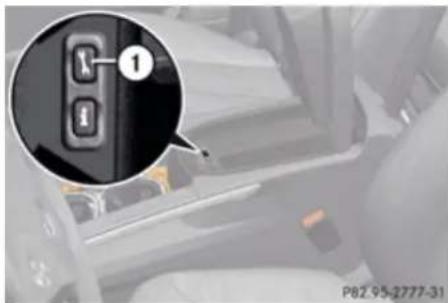
text_image
1 P82.95-2777-31① Roadside Assistance button

▶ Press and hold button √ for longer than 2 seconds.
A call to a Mercedes-Benz Roadside Assistance dispatcher will be initiated. The button will flash while the call is in progress. The message Connecting Call will appear in the multifunction display and the COMAND system is muted.
When the connection is established, the message Call Connected appears in the multifunction display. The Tele Aid system will transmit data generating the vehicle identification number, model, color and location (subject to availability of cellular and GPS signals).
The COMAND system display indicates that a Tele Aid call is in progress. While the call is connected you can change to the navigation menu by pressing the NAV button on the COMAND system. Spoken commands are not available.
A voice connection between the Roadside Assistance dispatcher and the occupants of the vehicle will be established.
▶ Describe the nature of the need for assistance.
The Mercedes-Benz Roadside Assistance dispatcher will either dispatch a qualified
▶▶
Controls in detail
Useful features
Mercedes-Benz technician or arrange to tow your vehicle to the nearest authorized Mercedes-Benz Center. For services such as labor and/or towing, charges may apply. Refer to the Roadside Assistance manual for more information.
The following is only available in the USA: Sign and Drive services: Services such as a jump start, a few gallons of fuel or the replacement of a flat tire with the vehicle spare tire are obtainable at no charge.
If the indicator lamp in the Roadside Assistance button is flashing continuously and there was no voice connection to the Response Center established, then the Tele Aid system could not initiate a Roadside Assistance call (e.g. the relevant cellular phone network is not available). The message Call Failed appears in the multifunction display.
▶ Terminating calls: Press button 📞 on the multifunction steering wheel.
or
▶ Press the respective button for ending a telephone call on the COMAND system.
Information button
▶ Open the storage compartment (▷ page 244).
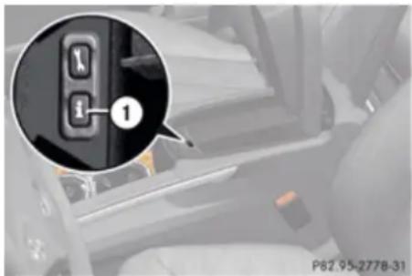
text_image
1 P82.95-2778-31① Information button
▶ Press and hold button • for longer than 2 seconds.
A call to the Customer Assistance Center will be initiated. The button ⚪️ will flash while the call is in progress. The message Connecting Call will appear in the multifunction display and the COMAND system is muted.
When the connection is established, the message Call Connected appears in the multifunction display. The Tele Aid system will transmit data generating the vehicle identification number, model, color and
location (subject to availability of cellular and GPS signals).
The COMAND system display indicates that a Tele Aid call is in progress. While the call is connected you can change to the navigation menu by pressing the NAV button on the COMAND system. Spoken commands are not available.
A voice connection between the Customer Assistance Center representative and the occupants of the vehicle will be established. Information regarding the operation of your vehicle, the nearest authorized Mercedes-Benz Center or Mercedes-Benz USA products and services is available to you.
For more details concerning the Tele Aid system, please visit www.mbusa.com (USA only), log in to "Owner's Online" and visit the "My Tele Aid" section to learn more.
If the indicator lamp in the Information button is flashing continuously and there was no voice connection to the Response Center established, then the Tele Aid system could not initiate an Information call (e.g. the relevant cellular phone network is not available). The message Call Failed appears in the multifunction display.
Controls in detail
Useful features
▶ Terminating calls: Press button 📞 on the multifunction steering wheel.
or
▶ Press the respective button for ending a telephone call on the COMAND system.
Call priority
If other service calls such as a Roadside Assistance call or Information call are active, an emergency call is still possible. In this case, the emergency call will take priority and override all other active calls.
The indicator lamp in the respective button flashes until the call is concluded. Emergency calls can only be terminated by a Response Center or Customer Assistance Center representative. All other calls can be terminated by pressing button 📞 on the multifunction steering wheel or the respective button for ending a telephone call on the COMAND system.
When a Tele Aid call has been initiated, the COMAND system audio is muted. The mobile phone is no longer connected to the COMAND system. If you must use this phone, we recommend that you use it only
with the vehicle at a standstill in a safe location.
Destination Download to the COMAND system
The components and operating principles of the COMAND system can be found in the separate COMAND operating instructions.
Destination Download allows you access to a database of over 10 million points of interest (POIs) that can be downloaded to your vehicle's navigation system. If you know the destination, the address can be downloaded, or can be provided with points of interests near your location.
The Response Center can transmit destination data to the COMAND system during the connection with the Roadside Assistance or Customer Assistance Center. The transmitted data can contain address details for a Mercedes-Benz Center or POIs.
Route guidance
You will be prompted to confirm that route guidance to the entered address is to be started.
▶ Select Yes using button ◀ or ▶ on the COMAND system.
▶ Press button OK on the COMAND system to confirm.
The system calculates the route and subsequently starts the route guidance to the defined address.
If you select No, you can save the address to your address book.
The Destination Download feature is available if the relevant mobile phone network is available and data connection is possible.
Remote door unlock
In case you have locked your vehicle unintentionally (e.g. SmartKey inside vehicle), and the reserve SmartKey is not available:
Controls in detail
Useful features
▶ Contact the Response Center at 1-800-756-9018 (in the USA) or 1-888-923-8367 (in Canada).
You will be asked to provide your password.
▶ Then return to your vehicle at the time arranged with the Response Center and pull the tailgate recessed handle (▷ page 90) for a minimum of 20 seconds until the SOS button is flashing.
The message Connecting Call appears in the multifunction display.
As an alternative, you may unlock the vehicle via Internet in the "My Tele Aid" section of "Owner's Online", using your ID and password (USA only).
The Response Center will then unlock your vehicle with the remote door unlocking feature.
i The remote door unlock feature is available if the relevant cellular phone network is available.
The SOS button will flash and the message Call Connected will appear in the multifunction display to indicate receipt of the door unlock command.
Once the vehicle is unlocked, a Response Center specialist will attempt to establish voice contact with the vehicle occupants. If the tailgate recessed handle was pulled for more than 20 seconds before door unlock authorization was received by the Response Center, you must wait 15 minutes before pulling the tailgate recessed handle again.
Stolen Vehicle Recovery services
In the event your vehicle was stolen:
▶ Report the incident to the police. The police will issue a numbered incident report.
Pass this number on to the Response Center along with your password. The Response Center will then attempt to covertly contact the vehicle's Tele Aid system. Once the vehicle is located, the Response Center will contact the local law enforcement and you. The vehicle's location will only be provided to law enforcement.
If the anti-theft alarm stays on for more than 30 seconds, a call to the Response Center is initiated automatically by the Tele
Aid system provided Tele Aid service was subscribed to and properly activated, and that necessary cellular service and GPS coverage are available. See “Anti-theft alarm system” (▷ page 81).
Garage door opener
The integrated remote control can operate up to three separately controlled devices compatible with HomeLink ^® or some other systems.
Warning!
Before programming the integrated remote control to a garage door opener or gate operator, make sure people and objects are out of the way of the device to prevent potential harm or damage. When programming a garage door opener, the door moves up or down. When programming a gate operator, the gate opens or closes.
Do not use the integrated remote control with any garage door opener that lacks safety stop and reverse features as required by U.S. federal safety standards (this includes any garage door opener model manufactured before April 1, 1982).
Controls in detail
Useful features
A garage door that cannot detect an object - signaling the door to stop and reverse - does not meet current U.S. federal safety standards.
When programming a garage door opener, park vehicle outside the garage.
Do not run the engine while programming the integrated remote control. Inhalation of exhaust gas is hazardous to your health. All exhaust gas contains carbon monoxide (CO), and inhaling it can cause unconsciousness and possible death.
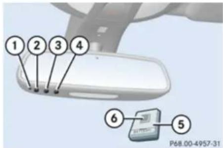
text_image
① ② ③ ④ ⑥ ⑤ P68.00-4957-31Interior rear view mirror with integrated remote control
① Indicator lamp
②③④ Signal transmitter button
⑤ Hand-held remote control (not part of vehicle equipment)
⑥ Hand-held remote control button
Programming the integrated remote control
▶ Step 1: Switch on the ignition.
▶ Step 2: If you have previously programmed a signal transmitter button and wish to retain its programming, proceed to step 3. or
If you are programming the integrated remote control for the first time, press and hold the two outer signal transmitter buttons ② and ④ and release them when indicator lamp ① begins to flash after approximately 20 seconds.
Do not hold the button for longer than 30 seconds.
This procedure erases any previous settings for all three channels and initializes the memory. If you later wish to program a second and/or third hand-held transmitter to the remaining two signal transmitter buttons, do not repeat this step and begin directly with step 3.
▶ Step 3: Hold the end of hand-held remote control ⑤ of the device you wish to train approximately 2 to 12 in (5 to 30 cm) away
from the signal transmitter button (②, ③ or ④) to be programmed, while keeping indicator lamp ① in view.
▶ Step 4: Using both hands, simultaneously press hand-held remote control button ⑥ and the desired signal transmitter button (②, ③ or ④). Do not release the buttons until step 5 is completed.
Indicator lamp ① will flash, first slowly and then rapidly.
i Indicator lamp ① flashes immediately the first time the signal transmitter button is programmed. If this button has already been programmed, the indicator lamp will start flashing after 20 seconds.
▶ Step 5: After indicator lamp ① changes from a slow to a rapidly flashing light, release the hand-held remote control button and the signal transmitter button.
▶ Step 6: Press and hold the just-trained signal transmitter button (②, ③ or ④) and observe indicator lamp ①.
If indicator lamp ① stays on constantly, programming is complete and your device should activate when the respective signal transmitter button (②, ③ or ④) is pressed and released.
Controls in detail
Useful features
If indicator lamp ① flashes rapidly for approximately 2 seconds and then turns to a constant light, continue with programming steps 8 through 12 as your garage door opener may be equipped with the “rolling code” feature.
▶ Step 7: To program the remaining two signal transmitter buttons, repeat the steps above starting with step 3.
Rolling code programming
To train a garage door opener (or other rolling code devices) with the rolling code feature, follow these instructions after completing the "Programming" portion (steps 1 through 6) of this text. (A second person may make the following training procedures quicker and easier.)
▶ Step 8: Locate the “training” button on the garage door opener motor head unit.
i Exact location and color of the button may vary by garage door opener brand. Depending on manufacturer, the “training” button may also be referred to as “learn” or “smart” button. If there is difficulty locating the transmitting button, refer to the garage door opener Operator’s Manual.
▶ Step 9: Press the “training” button on the garage door opener motor head unit.
The “training light” is activated.
You have 30 seconds to initiate the following two steps.
▶ Step 10: Return to the vehicle and firmly press, hold for 2 seconds and release the programmed signal transmitter button (②, ③ or ④).
▶ Step 11: Press, hold for 2 seconds and release same signal transmitter button a second time to complete the training process.
i Some garage door openers (or other rolling code equipped devices) may require you to press, hold for 2 seconds and release the same signal transmitter button a third time to complete the training process.
▶ Step 12: Confirm the garage door operation by pressing the programmed signal transmitter button (②, ③ or ④).
▶ Step 13: To program the remaining two signal transmitter buttons, repeat the steps above starting with step 3.
Gate operator/Canadian programming
Canadian radio-frequency laws require transmitter signals to “time-out” (or quit) after several seconds of transmission which may not be long enough for the integrated signal transmitter to pick up the signal during programming. Similar to this Canadian law, some U.S. gate operators are designed to “time-out” in the same manner.
If you live in Canada or if you are having difficulties programming a gate operator (regardless of where you live) by using the programming procedures, replace step 4 with the following:
▶ Step 4: Press and hold the signal transmitter button (②, ③ or ④). Do not release this button until it has been successfully trained.
While still holding down the signal transmitter button (②, ③ or ④), “cycle” your hand-held remote control button ⑥ as follows: Press and hold button ⑥ for 2 seconds, then release it for 2 seconds, and again press and hold it for 2 seconds. Repeat this sequence on the hand-held
Controls in detail
Useful features
remote control until the frequency signal has been learned.
Upon successful training, indicator lamp ① will flash slowly and then rapidly after several seconds.
▶ Proceed with programming step 5 and step 6 to complete.
Upon completion of programming the integrated remote control, make sure you retain the hand-held remote control that came with the garage door opener, gate operator or other device. You may need it for use in other vehicles, for future programming of an integrated remote control, or simply for continued use as a hand-held remote control to operate the respective device in other situations.
Reprogramming a single signal transmitter button
To program a device using a signal transmitter button previously trained, follow these steps:
▶ Switch on the ignition.
▶ Press and hold the desired signal transmitter button (②, ③ or ④). Do not release the button.
Indicator lamp ① will begin to flash after 20 seconds.
▶ Without releasing the signal transmitter button, proceed with programming starting with step 3.
Operation of integrated remote control
▶ Switch on the ignition.
▶ Select and press the appropriate integrated signal transmitter button (②, ③ or ④) to activate the remote controlled device.
The integrated remote control transmitter continues to send the signal as long as the button is pressed – up to 20 seconds.
Erasing the integrated remote control memory
If you sell your vehicle, erase the codes of all three channels.
▶ Switch on the ignition.
▶ Simultaneously press and hold outer signal transmitter buttons ② and ④, for approximately 20 seconds, until indicator lamp ① flashes rapidly. Do not hold for longer than 30 seconds.
The codes of all three channels are erased.
Programming tips
If you are having difficulty programming the integrated remote control, here are some helpful tips:
- Check the frequency of hand-held remote control ⑤ (typically located on the reverse side of the remote). The integrated remote control is compatible with radio-frequency devices operating between 280-390 MHz.
- Put a new battery in hand-held remote control ⑤. This will increase the likelihood of the hand-held remote control sending a faster and more accurate signal to the integrated remote control.
- While performing step 3, hold hand-held remote control ⑤ at different lengths and angles from the signal transmitter button (②, ③ or ④) you are programming. Attempt varying angles at the distance of 2
Controls in detail
Useful features
to 12 inches (5 to 30 cm) away or the same angle at varying distances.
- If another hand-held remote control is available for the same device, try the programming steps again using that other hand-held remote control. Make sure new batteries are in the hand-held remote control before beginning the procedure.
- Straighten the antenna wire from the garage door opener assembly. This may help improve transmitting and/or receiving signals.
Certain types of garage door openers are incompatible with the integrated remote control. If you should experience further difficulties with programming the integrated remote control, contact an authorized Mercedes-Benz Center, or call the Mercedes-Benz Customer Assistance Center (in the USA) at 1-800-FOR-MERCedes, or Customer Service (in Canada) at 1-800-387-0100.
i USA only: This device complies with Part 15 of the FCC Rules. Operation is subject to the following two conditions:
- This device may not cause harmful interference, and
- this device must accept any interference received, including interference that may cause undesired operation.
Any unauthorized modification to this device could void the user's authority to operate the equipment.
Canada only:
This device complies with RSS-210 of Industry Canada. Operation is subject to the following two conditions:
- This device may not cause interference, and
- this device must accept any interference received, including interference that may cause undesired operation of the device.
Any unauthorized modification to this device could void the user's authority to operate the equipment.
Compass
- Calling up the compass: Press button or on the multifunction steering wheel repeatedly until the off-road menu appears in the multifunction display. The compass displays the direction into which the vehicle is currently traveling: N, NE, E, SE, S, SW, W, or NW.
text_image
AIRMATIC Compass NE P34.12-5556-31Floormats
Warning!
Whenever you are using floormats, make sure there is enough clearance and that the floormats are securely fastened.
Floormats should always be securely fastened using the fastening equipment. Before driving off, check that the floormats are securely in place and adjust them if
Controls in detail
Useful features
necessary. A loose floormat could slip and hinder proper functioning of the pedals. Do not place several floormats on top of each other as this may impair pedal movement.
To install or remove the floormat more easily, move the driver's seat or front passenger seat as far to the rear as possible.

text_image
1 2 2 P68.00-4979-31① Retainer pin
② Eyelet
Removing: Pull floormat off of retainer pins ①.
Installing: Press floormat eyelets ② onto retainer pins ①.
Seat cover under third-row seats
If something falls under the third-row seats, you can remove the seat cover in order to reach under the seats.
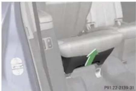
natural_image
Interior view of a vehicle showing a green arrow pointing to a component, with no visible text or symbols.Example passenger side
Removing: Fold the respective seat halfway in or out (▷ page 235).
▶ Reach into the recess in the seat cover.
▶ Pull the seat cover in direction of arrow.
Remove the seat cover to reach under the seats.
▶ Installing: Fold the seat halfway in or out (▷ page 235).
▶ Put the seat cover back into place using the guide pins.
▶ Press the seat cover down until it engages.
▶ Make sure the seat cover is engaged properly by folding the seat all the way in and out.
Operation
Vehicle equipment 264
The first 1000 miles (1500 km) ..... 264
At the gas station 265
Engine compartment 267
Tires and wheels 272
Winter driving 297
Driving instructions 299
Maintenance 315
Vehicle care 318
natural_image
Simple illustration of a fuel pump (no text or symbols)Operation
The first 1000 miles (1500 km)
Vehicle equipment
This Operator's Manual describes all features, standard or optional, potentially available for your vehicle at the time of purchase. Please be aware that your vehicle might not be equipped with all features described in this manual.
The first 1000 miles (1500 km)
The more cautiously you treat your vehicle during the break-in period, the more satisfied you will be with its performance later on.
- Drive your vehicle during the first 1000 miles (1500 km) at varying but moderate vehicle and engine speeds.
- During this period, avoid heavy loads (full throttle driving) and excessive engine speeds (no more than 2/3 of maximum rpm in each gear).
- Avoid accelerating by kickdown.
- Do not attempt to slow the vehicle down by shifting to a lower gear using the gear selector lever.
- Select gear ranges 3, 2 or 1 (▷ page 139) only when driving at moderate speeds (for hill driving).
After 1000 miles (1500 km) you may gradually increase vehicle and engine speeds to the permissible maximum.
All of the above instructions, as may apply to your vehicle type, also apply when driving the first 1000 miles (1500 km) after the engine, the transfer case, the center differential or the rear differential has been replaced.
Always obey applicable speed limits.
Operation
At the gas station
At the gas station
Refueling

Warning!
Gasoline and diesel fuels are highly flammable and poisonous. They burn violently and can cause serious injury. Never allow sparks, flames or smoking materials near gasoline or diesel fuel! Turn off the engine before refueling.
Whenever you are around gasoline or diesel fuel, avoid inhaling fumes and any skin or clothing contact. Extinguish all smoking materials.
Direct skin contact with fuels and the inhalation of fuel vapors are damaging your health.

Warning!
Overfilling of the fuel tank may create pressure in the system which could cause a gas discharge. This could cause the gas to spray back out when removing the fuel pump nozzle, which could cause personal injury.

Warning!
Do not fill diesel tanks with gasoline. Do not mix diesel fuel with gasoline. Otherwise the fuel system and engine could be damaged. In addition, the vehicle could catch fire.
Never use diesel fuel in vehicles with gasoline engine. Never refuel vehicles with gasoline engine with diesel fuel. Even small amounts of incorrect fuel will damage the fuel system and engine. Damage resulting from the use of non-approved fuels or fuel additives or resulting from mixing gasoline with diesel fuel or vice versa is not covered by the Mercedes-Benz Limited Warranty.
! If you have accidentally filled the tank with incorrect or non-approved fuel, do not switch on the ignition. Otherwise the incorrect or non-approved fuel will get into the fuel lines. The fuel system must be drained completely. Contact an authorized Mercedes-Benz Center to have the fuel system drained completely.
! Gasoline engine:
To prevent damage to the catalytic converters, only use premium unleaded gasoline in this vehicle.
Any noticeable irregularities in engine operation should be repaired promptly. Otherwise, excessive unburned fuel may reach the catalytic converter, causing it to overheat and potentially start a fire.
! Diesel engine:
When filling the diesel fuel tank using fuel containers, place a filling filter, a suede cloth or a clean flannel cloth as a filter. Otherwise, particles from the fuel container could clog the fuel lines and/or the diesel injection system.
! Diesel engine:
The engine is more susceptible to wear and damage if you use
- marine diesel fuel
- heating oil
- additives
The exhaust aftertreatment device will be seriously damaged if you use any other diesel fuel than ULTRA-LOW SULFUR HIGHWAY DIESEL FUEL (15 ppm SULFUR MAXIMUM).
The use of such non-approved fuels and/or special additives is not covered by the Mercedes-Benz Limited Warranty.
Operation
At the gas station
i Gasoline engine:
Only use premium unleaded gasoline with a minimum Posted Octane Rating of 91 (average of 96 RON/86 MON).
Information on gasoline quality can normally be found on the fuel pump. Please contact gas station personnel in case labels on the pump cannot be found.
For more information on gasoline, see “Premium unleaded gasoline (gasoline engine)” (▷ page 435), see “Fuel requirements” (▷ page 436), or contact an authorized Mercedes-Benz Center, or visit www.mbusa.com (USA only).
i Diesel engine:
Only use commercially available vehicular ULTRA-LOW SULFUR DIESEL FUEL
(15 ppm SULFUR MAXIMUM). Information on diesel quality can normally be found on the fuel pump. Please contact gas station personnel in case labels on the pump cannot be found.
For more information on diesel fuels, see "Fuel requirements" ( page 436), or contact an authorized Mercedes-Benz Center, or visit www.mbusa.com (USA only).
i Diesel engine:
If you have driven the vehicle until the tank is empty, the fuel system needs to be bled (▷ page 404).
The fuel filler flap is located on the right-hand side of the vehicle towards the rear.
Locking/unlocking the vehicle with the SmartKey automatically locks/unlocks the fuel filler flap.
In case that the central locking system does not release the fuel filler flap, see "Fuel filler flap" (▷ page 385).
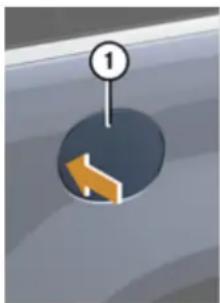
natural_image
Simple diagram showing a circular object with an arrow inside, marked with a numbered circle (no text or symbols)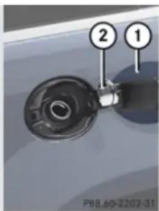
text_image
2 1 P88.60-2202-31① Fuel filler flap
② Fuel filler cap
▶ Turn off the engine.
Leaving the engine running and the fuel filler cap open can cause the yellow fuel tank reserve warning lamp to flash and the malfunction indicator lamp CHECK ENGINE (USA only) or 📄 (Canada only) to illuminate.
For more information, see also “Practical hints” (▷ page 379).
▶ Remove the SmartKey from the starter switch.
KEYLESS-GO: Open the driver's door (this puts the starter switch in position 0, same as with the SmartKey removed from the starter switch). The driver's door then can be closed again.
▶ Opening: Press fuel filler flap ① at the point indicated by the arrow.
▶ Turn fuel filler cap ② counterclockwise.
▶ Take off fuel filler cap ②.
! The fuel filler cap is tethered to the fuel filler neck. Do not drop the cap. It could damage the vehicle paint finish.
▶ Set fuel filler cap ② on fuel filler flap ①.
▶ Fully insert filler nozzle unit and refuel.
▶ Only fill your tank until the filler nozzle unit cuts out – do not top off or overfill.
Operation
Engine compartment
▶ Closing: Turn fuel filler cap ② clockwise until it audibly engages.
i Make sure to close the fuel filler flap before locking your vehicle as the flap locking pin prevents closing after you have locked the vehicle.
▶ Close fuel filler flap ①.
Low outside temperatures (diesel engine)
! Do not fill the tank with gasoline. Do not blend diesel fuel with gasoline or kerosene. The fuel system and engine will otherwise be damaged, which is not covered by the Mercedes-Benz Limited Warranty.
To prevent malfunctions, diesel fuel with improved cold flow characteristics is offered in the winter months. Check with your fuel retailer.
Check regularly and before a long trip
For information on quantities and requirements of operating agents, see “Fuels, coolants, lubricants, etc.” (▷ page 432).
Check the following:
• Engine oil level (▷ page 269)
- Tire inflation pressure (▷ page 281)
• Coolant level (▷ page 271)
• Vehicle lighting (▷ page 388)
- Washer system and headlamp cleaning system (▷ page 271)
- Brake fluid
Engine compartment
Hood

Warning!
Do not pull the release lever while the vehicle is in motion. Otherwise the hood could be forced open by passing air flow. This could cause the hood to come loose and injure you and/or others.
Opening

Warning!
If you see flames or smoke coming from the engine compartment, or if the coolant temperature display indicates that the engine is overheated, do not open the hood. Move away from vehicle and do not open the hood until the engine has cooled. If necessary, call the fire department.

Warning!
You could be injured when the hood is open - even when the engine is turned off. Parts of the engine can become very hot. To prevent burns, let the engine cool off completely before touching any
Operation
Engine compartment
components on the vehicle. Comply with all relevant safety precautions.

Warning!
To help prevent personal injury, stay clear of moving parts when the hood is open and the engine is running.
The radiator fan may continue to run for approximately 30 seconds or may even restart after the engine has been turned off. Stay clear of fan blades.

Warning!
Vehicles with gasoline engine:
The engine is equipped with a transistorized ignition system. Because of the high voltage it is dangerous to touch any components (ignition coils, spark plug sockets, diagnostic socket) of the ignition system
• with the engine running
• while starting the engine
- when the ignition is switched on and the engine is turned manually

Warning!
Vehicles with diesel engine:
The engine is equipped with a high-voltage electronic control unit for the injection system. Because of the high voltage it is dangerous to touch any components of the injection system (injectors, electrical wires)
• with the engine running
• while starting the engine
- when the ignition is switched on
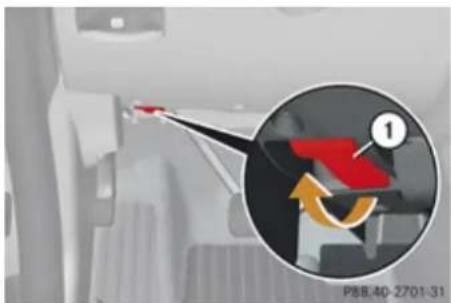
natural_image
Interior view of a vehicle showing a red arrow pointing to a vehicle's side panel, with an inset magnified view highlighting the component (no text or symbols)① Hood lock release lever
▶ Pull release lever ①.
The hood is unlocked.
! To avoid damage to the windshield wipers or hood, never open the hood if the wiper arms are folded forward away from the windshield.

natural_image
Close-up of a Mercedes-Benz car dashboard with a highlighted component (no visible text or symbols)② Handle for opening the hood
▶ Press and hold handle ②.
The hood is unlocked.
▶ Pull up on the hood in direction of arrow and then release it.
The hood will be automatically held open at shoulder height by gas-filled struts.
Operation
Engine compartment
Closing

Warning!
When closing the hood, use extreme caution not to catch hands or fingers. Be careful that you do not close the hood on anyone.
Make sure the hood is securely engaged before driving off. Do not continue driving if the hood can no longer engage after an accident, for example. The hood could otherwise come loose while the vehicle is in motion and injure you and/or others.
▶ Let the hood drop from a height of approximately 1 ft (30 cm).
▶ Check to make sure the hood is fully closed.
If you can raise the hood at a point above the headlamps, then it is not properly closed. Open it again and let it drop with somewhat greater force.
Engine oil
The amount of oil your engine needs will depend on a number of factors, including driving style. Increased oil consumption can occur when the vehicle is new or the vehicle is driven frequently at higher engine speeds. Engine oil consumption checks should only be made after the vehicle break-in period.
! Do not use any special lubricant additives, as these may damage the drive assemblies. Using special additives not approved by Mercedes-Benz may cause damage not covered by the Mercedes-Benz Limited Warranty. For further information contact an authorized Mercedes-Benz Center.
Notes on checking engine oil level
When checking the oil level the vehicle must be parked on level ground and the vehicle must have been stationary for at least 5 minutes with the engine turned off.
Checking engine oil level
▶ Open the hood (▷ page 267).
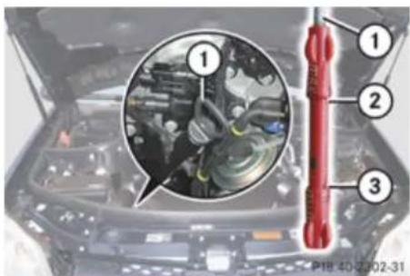
text_image
Technical diagram of engine components with numbered parts and a magnified inset showing mechanical assemblyExample illustration GL 450 (GL 320 BlueTEC, GL 550 similar)
① Oil dipstick
② Upper (max) mark
③ Lower (min) mark
▶ Pull out oil dipstick ①.
▶ Wipe oil dipstick ① clean.
Operation
Engine compartment
▶ Fully insert oil dipstick ① into the dipstick guide tube.
▶ Pull out oil dipstick ① again after approximately 3 seconds to obtain accurate reading.
The oil level is correct when it is between lower (min) mark ③ and upper (max) mark ② of oil dipstick ①.
The filling quantity between the upper and lower marks on the oil dipstick is approximately 2.1 US qt. (2.0 l).
▶ If necessary, add engine oil.
For more information on engine oil, see "Fuels, coolants, lubricants etc." (▷ page 432).
For information on messages in the multifunction display concerning engine oil, see the "Practical hints" section (▷ page 361).
Adding engine oil
! Only use approved engine oils and oil filters required for vehicles with Maintenance System. For a listing of approved engine oils and oil filters, contact
an authorized Mercedes-Benz Center or visit www.mbusa.com (USA only). Using engine oils and oil filters of specification other than those expressly required for the Maintenance System, or changing of oil and oil filter at change intervals longer than those called for by the Maintenance System will result in engine or emission control system damage not covered by the Mercedes-Benz Limited Warranty.
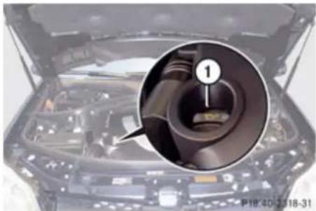
natural_image
Close-up of a car engine bay with a magnified inset showing internal components (no visible text or symbols)Example illustration GL 450 (GL 320 BlueTEC, GL 550 similar)
① Filler cap
▶ Unscrew filler cap ① from filler neck.
▶ Add engine oil as required. Be careful not to overfill with oil.
Be careful not to spill any oil when adding. Avoid environmental damage caused by oil entering the ground or water.
! Excess oil must be siphoned or drained off. It could cause damage to the engine and emission control system not covered by the Mercedes-Benz Limited Warranty.
▶ Screw filler cap ① back on filler neck.
For more information on engine oil, see the "Technical data" section (▷ page 432) and (▷ page 434).
Transmission fluid level
The transmission fluid level does not need to be checked. If you notice transmission fluid loss or gearshifting malfunctions, have an authorized Mercedes-Benz Center check the transmission.
Operation
Engine compartment
Coolant level
The engine coolant is a mixture of water and anticorrosion/antifreeze.
When checking the coolant level, the vehicle must be parked on level ground, and the coolant temperature must be below 158°F (70°C).

Warning!
In order to avoid any potentially serious burns:
- Use extreme caution when opening the hood if there are any signs of steam or coolant leaking from the cooling system, or if the coolant temperature indicator indicates that the coolant is overheated.
- Do not remove pressure cap on coolant reservoir if coolant temperature is above 158°F (70°C). Allow engine to cool down before removing cap. The coolant reservoir contains hot fluid and is under pressure.
- Using a rag, slowly open the cap approximately 1/2 turn to relieve excess pressure. If opened immediately,
scalding hot fluid and steam will be blown out under pressure.
- Do not spill antifreeze on hot engine parts. Antifreeze contains ethylene glycol which may burn if it comes into contact with hot engine parts.
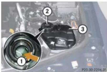
text_image
Diagram of a car engine component with numbered parts and an inset magnified view showing a camera lens assembly.① Marking bar in the expansion tank
② Cap
③ Coolant expansion tank
▶ Using a rag, turn cap ② slowly approximately 12 counterclockwise to release any excess pressure.
▶ Continue turning cap ② counterclockwise and remove it.
The coolant level is correct if the level
• for cold coolant: reaches marking bar
① in expansion tank ③
• for warm coolant: is approximately 0.6 in (1.5 cm) higher
▶ Add coolant as required.
▶ Replace and tighten cap ②.
For more information on coolant, see the "Technical data" section (▷ page 438) and (▷ page 433).
Washer system and headlamp cleaning system

Warning!
Washer solvent/antifreeze is highly flammable. Do not spill washer solvent/antifreeze on hot engine parts, because it may ignite and burn. You could be seriously burned.
! Always use washer solvent/antifreeze where temperatures may fall below freezing point. Failure to do so could result in damage to the washer system/fluid reservoir.
Operation
Tires and wheels
! Only use washer fluid which is suitable for plastic lenses. Improper washer fluid can damage the plastic lenses of the headlamps.
! Do not use distilled or de-ionized water in the washer fluid reservoir. Otherwise, the washer fluid level sensor could be damaged.
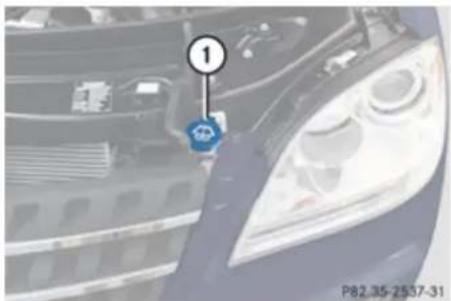
natural_image
Close-up of a car's head panel with a blue logo and number 1, no visible text or symbols on the main subject.① Cap for washer fluid reservoir
Fluid for the washer system, rear window washer system and the headlamp cleaning system is supplied from the washer fluid reservoir.
During all seasons, add MB Windshield Washer Concentrate "MB SummerFit" to water. Premix the washer fluid in a suitable container.
Opening washer fluid reservoir: Pull tab of cap ① upwards.
▶ Refill the washer fluid reservoir with MB Windshield Washer Concentrate "MB SummerFit" and water (or commercially available premixed washer solvent/antifreeze, depending on ambient temperatures) (▷ page 440).
▶ Closing washer fluid reservoir: Press cap
① onto filler hole until it engages.
For more information, see "Washer system and headlamp cleaning system" (▷ page 434).
Tires and wheels
Safety notes
Contact an authorized Mercedes-Benz Center for information on tested and recommended rims and tires for summer and winter operation. They can also offer advice concerning tire service and purchase.
Warning!
Replace rims or tires with the same designation, manufacturer and type as shown on the original part. For further information contact an authorized Mercedes-Benz Center. If incorrectly sized rims and tires are mounted, the wheel brakes or suspension components can be damaged. Also, the correct operating clearance of the wheels and the tires may no longer be correct.
Warning!
Worn, old tires can cause accidents. If the tire tread is worn to minimum tread depth, or if the tires have sustained damage, replace them.
When replacing rims, only use genuine Mercedes-Benz wheel bolts specified for the particular rim type. Failure to do so can
Operation
Tires and wheels
result in the bolts loosening and possibly an accident.
Retreaded tires are not tested or recommended by Mercedes-Benz, since previous damage cannot always be recognized on retreads. The operating safety of the vehicle cannot be assured when such tires are used.

Warning!
If you feel a sudden significant vibration or ride disturbance, or you suspect that possible damage to your vehicle has occurred, you should turn on the hazard warning flashers, carefully slow down, and drive with caution to an area which is a safe distance from the road.
Inspect the tires and the vehicle underbody for possible damage. If the vehicle or tires appear unsafe, have the vehicle towed to the nearest authorized Mercedes-Benz Center or tire dealer for repairs.

Warning!
Do not drive with a flat tire. A flat tire affects the ability to steer or brake the vehicle. You could lose control of the vehicle. Continued driving with a flat tire or driving at high
speed with a flat tire will cause excessive heat build-up and possibly a fire.
Important guidelines
- Only use sets of tires and rims of the same type and make.
- Tires must be of the correct size for the rim.
- Break in new tires for approximately 60 miles (100 km) at moderate speeds.
- Regularly check the tires and rims for damage. Dented or bent rims can cause tire inflation pressure loss and damage to the tire beads.
- If vehicle is heavily loaded, check tire inflation pressure and correct as required.
- Do not allow your tires to wear down too far. Adhesion properties on wet roads are sharply reduced at tread depths of less than 1/8 in (3 mm).
- When replacing individual tires, you should mount new tires on the front wheels first (on vehicles with same-sized wheels all around).
Tire care and maintenance

Warning!
Regularly check the tires for damage. Damaged tires can cause tire inflation pressure loss. As a result, you could lose control of your vehicle.
Worn, old tires can cause accidents. If the tire tread is worn to minimum tread depth, or if the tires have sustained damage, replace them.
Check the tire inflation pressure at least every other week. For more information on checking tire inflation pressure, see "Recommended tire inflation pressure" (▷ page 279).
Tire inspection
Every time you check the tire inflation pressure, you should also inspect your tires for the following:
• excessive treadwear (> page 274)
- cord or fabric showing through the tire's rubber
• bumps, bulges, cuts, cracks or splits in the tread or side of the tire
Operation
Tires and wheels
Replace the tire if you find any of the above conditions.
Make sure you also inspect the spare tire periodically for condition and inflation. Spare tires will age and become worn over time even if never used, and thus should be inspected and replaced when necessary.
Life of tire

Warning!
Tires and spare tire should be replaced after 6 years, regardless of the remaining tread.
The service life of a tire is dependent upon varying factors including but not limited to:
- Driving style
- Tire inflation pressure
- Distance driven
Tread depth

Warning!
Although the applicable federal motor vehicle safety laws consider a tire to be worn when the treadwear indicators (TWI) become visible at approximately 116 in
(1.6 mm), we recommend that you do not allow your tires to wear down to that level. As tread depth approaches ^1/_8 in (3 mm), the adhesion properties on a wet road are sharply reduced.
Depending upon the weather and/or road surface (conditions), the tire traction varies widely.
Do not allow your tires to wear down too far. Adhesion properties on wet roads are sharply reduced at tread depths of less than 18 in (3 mm).
Treadwear indicators (TWI) are required by law. These indicators are located in six places on the tread circumference and become visible at a tread depth of approximately 116 in (1.6 mm), at which point the tire is considered worn and should be replaced.
The recommended minimum tire tread depth for summer tires is 18 in (3 mm). The recommended minimum tire tread depth for winter tires is 16 in (4 mm).
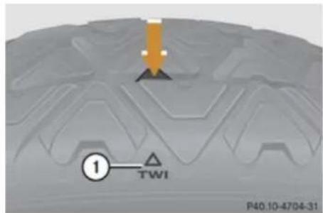
text_image
① TWI P40.10-4704-31① TWI (Tread Wear Indicator)
The treadwear indicator appears as a solid band across the tread.
Storing tires
Keep unmounted tires in a cool, dry place with as little exposure to light as possible. Protect tires from contact with oil, grease and fuels.
Cleaning tires
! Never use a round nozzle to power wash tires. The intense jet of water can result in damage to the tire.
Always replace a damaged tire.
Operation
Tires and wheels
Direction of rotation
Unidirectional tires offer added advantages, such as better hydroplaning performance. To benefit, however, you must make sure the tires rotate in the direction specified.
An arrow on the sidewall indicates the intended direction of rotation (spinning) of the tire.
Spare wheels may be mounted against the direction of rotation (spinning) even with a unidirectional tire for temporary use only until the regular drive wheel has been repaired or replaced. Always observe and follow applicable temporary use restrictions and speed limitations indicated on the spare wheel.
Loading the vehicle
Two labels on your vehicle show how much weight it may properly carry.
(1) The Tire and Loading Information placard can be found on the driver's door B-pillar. This placard tells you important information about the number of people that can be in the vehicle and the total weight that can be carried in the vehicle. It also contains information on the proper size and recommended tire inflation pressures for the original equipment tires on your vehicle.
(2) The certification label, also found on the driver's door B-pillar. It tells you about the gross weight capacity of your vehicle, called the Gross Vehicle Weight Rating (GVWR). The GVWR includes the weight of the vehicle, all occupants, fuel and cargo. The certification label also tells you about the front and rear axle weight capacity, called the Gross Axle Weight Rating (GAWR).
The GAWR is the total allowable weight that can be carried by a single axle (front or rear). Never exceed the GVWR or GAWR for either the front axle or rear axle.
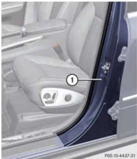
natural_image
Interior view of a car's seat and dashboard (no visible text or symbols)① Driver's door B-pillar
Following is a discussion on how to work with the information contained on the Tire and Loading Information placard with regards to loading your vehicle.
▶▶
Operation
Tires and wheels
Tire and Loading Information
Warning!
Do not overload the tires by exceeding the specified load limit as indicated on the Tire and Loading Information placard on the driver's door B-pillar. Overloading the tires can overheat them, possibly causing a blowout. Overloading the tires can also result in handling or steering problems, or brake failure.
Tire and Loading Information placard
Data shown on Tire and Loading Information placard example are for illustration purposes only. Load limit data are specific to each vehicle and may vary from data shown in the following illustration. Refer to Tire and Loading Information placard on vehicle for actual data specific to your vehicle.
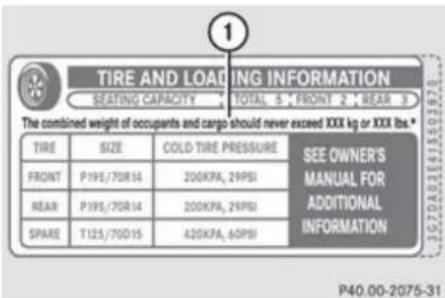
text_image
TIRE AND LOADING INFORMATION SEATING CAPACITY TOTAL 5 FRONT 2 REAR 3 The combined weight of occupants and cargo should never exceed XXX kg or XXX lbs.* TIRE SIZE COLD TIRE PRESSURE SEE OWNER'S FRONT P195/70R14 200KPA, 29PSI MANUAL FOR REAR P195/70R14 200KPA, 29PSI ADDITIONAL SPARE T125/70D15 420KPA, 60PSI INFORMATION P40.00-2075-31① Load limit information on the Tire and Loading Information placard
The Tire and Loading Information placard showing the load limit information is located on the driver's door B-pillar (▷ page 275).
- Locate the statement "The combined weight of occupants and cargo should never exceed XXX kilograms or XXX lbs." on the Tire and Loading Information placard.
The combined weight of all occupants, cargo/luggage and trailer tongue load (if applicable) should never exceed the weight referenced in that statement.
Seating capacity
The seating capacity gives you important information on the number of occupants that can be in the vehicle. Observe front and rear seating capacity. The Tire and Loading Information placard showing the seating capacity is located on the driver's door B-pillar (▷ page 275).
Data shown on Tire and Loading Information placard example are for illustration purposes only. Seating capacity data are specific to each vehicle and may vary from data shown in the following illustration. Refer to Tire and Loading Information placard on vehicle for actual data specific to your vehicle.
Operation
Tires and wheels
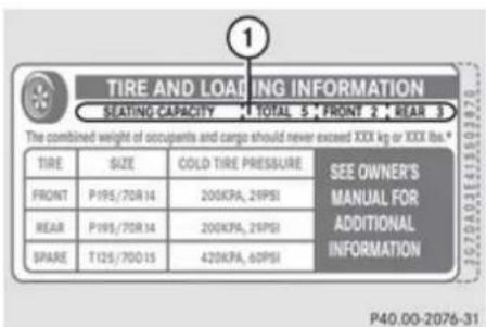
text_image
TIRE AND LOADING INFORMATION SEATING CAPACITY 1 TOTAL 5 FRONT 2 REAR 3 The combined weight of occupants and cargo should never exceed XXX kg or XXX lbs.* TIRE SIZE COLD TIRE PRESSURE SEE OWNER'S FRONT P195/70R 14 200KPA, 21PSI MANUAL FOR REAR P195/70R 14 200KPA, 21PSI ADDITIONAL SPARE T125/70D 15 420KPA, 60PSI INFORMATION P40.00-2076-31① Seating capacity information on the Tire and Loading Information placard
Steps for determining correct load limit
The following steps have been developed as required of all manufacturers under Title 49, Code of U.S. Federal Regulations, Part 575 pursuant to the "National Traffic and Motor Vehicle Safety Act of 1966".
Step 1: Locate the statement "The combined weight of occupants and cargo should never exceed XXX kg or XXX lbs." on your vehicle's Tire and Loading Information placard.
▶ Step 2: Determine the combined weight of the driver and passengers that will be riding in your vehicle.
▶ Step 3: Subtract the combined weight of the driver and passengers from XXX kilograms or XXX lbs.
Step 4: The resulting figure equals the available amount of cargo and luggage load capacity. For example, if the "XXX" amount equals 1400 lbs and there will be five 150 lbs passengers in your vehicle, the amount of available cargo and luggage load capacity is 650 lbs (1400 - 750 (5 x 150) = 650 lbs).
▶ Step 5: Determine the combined weight of luggage and cargo being loaded on the vehicle. That weight may not safely exceed the available cargo and luggage load capacity calculated in step 4.
▶ Step 6 (if applicable): If your vehicle will be towing a trailer, load from your trailer will be transferred to your vehicle. Consult this manual to determine how this reduces the available cargo and luggage load capacity of your vehicle (▶ page 279).
The following table shows examples on how to calculate total and cargo load capacities with varying seating configurations and number and size of occupants. The following examples use a load limit of 1500 lbs. This is for illustration purposes only. Make sure you are using the actual load limit for your vehicle stated on the vehicle's Tire and Loading Information placard ( page 276).
Operation
Tires and wheels
| Example | Combined weight limit of occupants and cargo from Tire and Loading Information placard | Number of occupants (driver and passengers) | Seating configuration | Occupants weight | Combined weight of all occupants | Available cargo/luggage and trailer tongue weight (total load limit from Tire and Loading Information placard minus combined weight of all occupants) |
| 1 | 1500 lbs 5 front: 2 | rear: 3 | Occupant 1: 150 lbs Occupant 2: 180 lbs Occupant 3: 160 lbs Occupant 4: 140 lbs Occupant 5: 120 lbs | 750 lbs 1500 lbs - 750 lbs = 750 lbs | ||
| 2 | 1500 lbs 3 front: 1 | rear: 2 | Occupant 1: 200 lbs Occupant 2: 190 lbs Occupant 3: 150 lbs | 540 lbs 1500 lbs - 540 lbs = 960 lbs | ||
| 3 | 1500 lbs | 1 | front: 1 | Occupant 1: 150 lbs | 150 lbs | 1500 lbs - 150 lbs = 1350 lbs |
The higher the weight of all occupants, the less cargo and luggage load capacity is available.
For more information, see "Trailer tongue load" (▷ page 279).
Certification label
Even after careful determination of the combined weight of all occupants, cargo and the trailer tongue load (if applicable) (> page 279) as to not exceed the permissible load limit, you must make sure your vehicle never exceeds the Gross Vehicle Weight Rating (GVWR) and the Gross Axle Weight Rating (GAWR) for either the front or
rear axle. You can obtain the GVWR and GAWR from the certification label. The certification label can be found on the driver's door B-pillar, see the "Technical data" section (▷ page 421).
Gross Vehicle Weight Rating (GVWR): The total weight of the vehicle, all occupants, all cargo, and the trailer tongue load must never exceed the GVWR.
Operation
Tires and wheels
Gross Axle Weight Rating (GAWR): The total allowable weight that can be carried by a single axle (front or rear).
To assure that your vehicle does not exceed the maximum permissible weight limits (GVWR and GAWR for front and rear axle), have the loaded vehicle (including driver, passengers and all cargo and, if applicable, trailer fully loaded) weighed on a suitable commercial scale.
Trailer tongue load
The tongue load of any trailer is an important weight to measure because it affects the load you can carry in your vehicle. If a trailer is towed, the tongue load must be added to the weight of all occupants riding and any cargo you are carrying in the vehicle. The tongue load typically is between 8% and 15% of the trailer weight and everything loaded in it.
Recommended tire inflation pressure
Warning!
Follow recommended tire inflation pressures.
Do not underinflate tires. Underinflated tires wear excessively and/or unevenly, adversely affect handling and fuel economy, and are more likely to fail from being overheated.
Do not overinflate tires. Overinflated tires can adversely affect handling and ride comfort, wear unevenly, increase stopping distance, and result in sudden deflation (blowout) because they are more likely to become punctured or damaged by road debris, potholes etc.
Do not overload the tires by exceeding the specified load limit as indicated on the Tire and Loading Information placard on the driver's door B-pillar. Overloading the tires can overheat them, possibly causing a blowout. Overloading the tires can also result in handling or steering problems, or brake failure.
Your vehicle is equipped with the Tire and Loading Information placard located on the driver's door B-pillar (▷ page 275).
The tire inflation pressure should be checked regularly and should only be adjusted on cold tires. The tires can be considered cold if the vehicle has been parked for at least 3 hours or driven less than 1 mile (1.6 km).
Follow recommended cold tire inflation pressures listed on Tire and Loading Information placard on the driver's door B-pillar.
Keeping the tires properly inflated provides the best handling, tread life and riding comfort.
In addition to the Tire and Loading Information placard on the driver's door B-pillar, also consult the tire inflation pressure label (if available) on the inside of the filler flap for any additional information pertaining to special driving situations. For more information, see “Important notes on tire inflation pressure” ( page 280).
Data shown on Tire and Loading Information placard example are for illustration purposes only. Tire data are specific to each vehicle and may vary from data shown in the following illustration. Refer to Tire and Loading Information placard on vehicle for actual data specific to your vehicle.
Operation
Tires and wheels
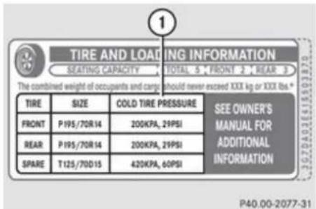
text_image
TIRE AND LOADING INFORMATION SEATING CAPACITY TOTAL 5 FRONT 2 REAR 3 The combined weight of occupants and cargo should never exceed XXX kg or XXX lbs.* TIRE SIZE COLD TIRE PRESSURE SEE OWNER'S FRONT P195/70R14 200KPA, 29PSI MANUAL FOR REAR P195/70R14 200KPA, 29PSI ADDITIONAL SPARE T125/70D15 420KPA, 60PSI INFORMATION P40.00-2077-31① Tire and Loading Information placard with recommended cold tire inflation pressures
The Tire and Loading Information placard lists the recommended cold tire inflation pressures for maximum loaded vehicle weight. The tire inflation pressures listed apply to the tires installed as original equipment.
Important notes on tire inflation pressure

Warning!
If the tire inflation pressure drops repeatedly, check the tires for punctures from foreign objects and/or whether air is
leaking from the valves or from around the rim.
Tire temperature and tire inflation pressure are also increased while driving, depending on the driving speed and the tire load.
If you will be driving your vehicle at high speeds of 100 mph (160 km/h) or higher, where it is legal and conditions allow, consult the tire inflation pressure label on the inside of the fuel filler flap (if available) on how to adjust the cold tire inflation pressure. If you do not adjust the tire inflation pressure, excessive heat can build up and result in sudden tire failure.
If your vehicle is not equipped with the tire inflation pressure label on the inside of the fuel filler flap, contact an authorized Mercedes-Benz Center for proper tire inflation pressure.
Driving comfort may be reduced when the tire inflation pressure is adjusted to the value for speeds above 100 mph (160 km/h) as specified on the tire inflation pressure label located on the inside of the fuel filler flap.
Make sure to readjust the tire inflation pressure for normal driving speeds. You
should wait until the tires are cold before adjusting the tire inflation pressure.
Some vehicles may have supplemental tire inflation pressure information for vehicle loads less than the maximum loaded vehicle condition. If such information is provided, it can be found on the tire inflation pressure label located on the inside of the fuel filler flap (▷ page 265).
Tire inflation pressure changes by approximately 1.5 psi (0.1 bar) per 18°F (10°C) of air temperature change. Keep this in mind when checking tire inflation pressure where the temperature is different from the outside temperature.
Potential problems associated with underinflated and overinflated tires
Underinflated tires

Warning!
Follow recommended tire inflation pressures.
Do not underinflate tires. Underinflated tires wear excessively and/or unevenly, adversely affect handling and fuel economy, and are more likely to fail from being overheated.
Operation
Tires and wheels
Underinflated tires can
- cause excessive and uneven tire wear
• adversely affect fuel economy - lead to tire failure from being overheated
• adversely affect handling characteristics
Overinflated tires

Warning!
Follow recommended tire inflation pressures.
Do not overinflate tires. Overinflated tires can adversely affect handling and ride comfort, wear unevenly, increase stopping distance, and result in sudden deflation (blowout) because they are more likely to become punctured or damaged by road debris, potholes etc.
Overinflated tires can
• adversely affect handling characteristics
- cause uneven tire wear
- be more prone to damage from road hazards
• adversely affect ride comfort
• increase stopping distance
Checking tire inflation pressure
Safety notes

Warning!
Follow recommended tire inflation pressures.
Do not underinflate tires. Underinflated tires wear excessively and/or unevenly, adversely affect handling and fuel economy, and are more likely to fail from being overheated.
Do not overinflate tires. Overinflated tires can adversely affect handling and ride comfort, wear unevenly, increase stopping distance, and result in sudden deflation (blowout) because they are more likely to become punctured or damaged by road debris, potholes etc.
Do not overload the tires by exceeding the specified load limit as indicated on the Tire and Loading Information placard on the driver's door B-pillar. Overloading the tires can overheat them, possibly causing a blowout. Overloading the tires can also result in handling or steering problems, or brake failure.
Check the tire inflation pressure at least every other week.
Check and adjust the tire inflation pressure when the tires are cold. The tires can be considered cold if the vehicle has been parked for at least 3 hours or driven less than 1 mile (1.6 km).
If you check the tire inflation pressure when the tires are warm (the vehicle has been driven for several miles or sitting less than 3 hours), the reading will be approximately 4 psi (0.3 bar) higher than the cold reading. This is normal. Do not let air out to match the specified cold tire inflation pressure. Otherwise, the tire will be underinflated.
Checking tire inflation pressure manually
Follow the steps below to achieve correct tire inflation pressure:
▶ Remove the cap from the valve on one tire.
▶ Firmly press a tire gauge onto the valve.
Read the tire inflation pressure on the tire gauge and check against the recommended tire inflation pressure on the Tire and Loading Information placard on the driver's door B-pillar (▷ page 275). If necessary, add air to achieve the recommended tire inflation pressure.
▶▶
Operation
Tires and wheels
If you have overfilled the tire, release tire inflation pressure by pushing the metal stem of the valve with e.g. a tip of a pen. Then recheck the tire inflation pressure with the tire gauge.
▶ Install the valve cap.
▶ Repeat this procedure for each tire.
Run Flat Indicator (Canada only)
While the vehicle is being driven, the Run Flat Indicator monitors the set tire inflation pressures by evaluating each wheel's rotational speed. This allows the system to detect a significant loss of pressure in a tire. If a wheel's rotational speed changes due to falling tire inflation pressure, you will see a corresponding warning message in the multifunction display.
The Run Flat Indicator may function in a restricted manner or with a delay
-
when snow chains are mounted to the vehicle
• in the presence of ice and snow -
when you are driving on a loose surface (e.g. sand or gravel)
- when you are driving in a very sporty manner (involving rapid acceleration or high speeds in curves)
Warning!
When the multifunction display shows the message Tire Pressure Check Tires, one or more of your tires is significantly underinflated. You should stop and check your tires as soon as possible, and inflate them to the proper tire inflation pressure as indicated on the vehicle's Tire and Loading Information placard or, if available, on the tire inflation pressure label.
Driving on a significantly underinflated tire causes the tire to overheat and can lead to tire failure. Underinflation also reduces fuel efficiency and tire tread life, and may affect the vehicle's handling and stopping ability. Each tire, including the spare, should be checked every other week when cold and set to the recommended tire inflation pressure as specified on the Tire and Loading Information placard on the driver's door B-pillar or, if available, on the tire inflation pressure label located on the inside of the fuel filler flap.
The recommended tire inflation pressures for your vehicle can be found on the Tire and Loading Information placard located on the driver's door B-pillar (▷ page 275) or, if available, on the tire inflation pressure label on the inside of the fuel filler flap (▷ page 266). The tire inflation pressures are not listed in the Operator's Manual.
Warning!
The Run Flat Indicator does not provide a warning for wrongly selected tire inflation pressures. Always adjust tire inflation pressure according to the Tire and Loading Information placard on the driver's door B-pillar or, if available, on the tire inflation pressure label located on the inside of the fuel filler flap.
The Run Flat Indicator does not replace regular checks of the tire inflation pressures since a gradual pressure loss in more than one tire cannot be detected by the Run Flat Indicator.
The Run Flat Indicator is not able to issue a warning due to a sudden dramatic loss of tire inflation pressure (e.g. tire blowout caused by a foreign object). In this case bring the vehicle to a halt by carefully
Operation
Tires and wheels
applying the brakes and avoiding abrupt steering maneuvers.
Restarting the Run Flat Indicator
The Run Flat Indicator must be restarted in the following situations:
• after you have changed the tire inflation pressure
• after you have replaced the wheels or tires
• after you have installed new wheels or tires
Using the Tire and Loading Information placard on the driver's door B-pillar or, if available, the tire inflation pressure label on the inside of the fuel filler flap, make sure the tire inflation pressure of all four tires is correct.

Warning!
The Run Flat Indicator can only warn you in a reliable manner if you have set the correct tire inflation pressures for each tire.
If an incorrect tire inflation pressure was set, the system will monitor the pressure according to the incorrect value.
▶ Switch on the ignition.
▶ Make sure the standard display appears in the multifunction display (▷ page 152).
▶ Press button 🏠 or ▲ on the multifunction steering wheel repeatedly until the following message appears in the multifunction display:
Run Flat Indicator
Active
Menu: R-Button
▶ Press the reset button (▷ page 147). The following message will appear in the multifunction display: Restart Run Flat Indicator?
▶ If you wish to confirm: Press button + .
The following message will appear in the multifunction display: Run Flat Indicator Restarted
After a certain “learning phase”, the Run Flat Indicator checks the set pressure values for all four tires.
▶ If you wish to cancel: Press button —.
or
▶ Wait until the message
Restart
Run Flat Indicator?
disappears.
Tire Pressure Monitoring System (TPMS), (USA only)
Your vehicle is equipped with a Tire Pressure Monitoring System (TPMS). It measures the tire inflation pressure in the vehicle's tires and issues warnings in case of pressure loss. The Tire Pressure Monitoring System (TPMS) is equipped with a combination low tire pressure/TPMS malfunction telltale in the instrument cluster. Depending on how the telltale illuminates, it indicates a low tire pressure condition or a malfunction in the TPMS system itself:
- If the telltale illuminates continuously, one or more of your tires are significantly
Operation
Tires and wheels
underinflated. There is no malfunction in the TPMS.
- If the telltale flashes for 60 seconds and then stays illuminated, the TPMS system itself is not operating properly.
The TPMS only functions on wheels that are equipped with the proper electronic sensors. It monitors the tire inflation pressure, as selected by the driver, in all four tires. A warning is issued to alert you to a decrease in pressure in one or more of the tires.

Warning!
The TPMS does not indicate a warning for wrongly selected inflation pressures. Always adjust tire inflation pressure according to the Tire and Loading Information placard or, if available, on the supplemental tire inflation pressure information on the inside of the fuel filler flap.
The TPMS is not able to issue a warning due to a sudden dramatic loss of pressure (e.g. tire blowout caused by a foreign object). In this case bring the vehicle to a halt by carefully applying the brakes and avoiding abrupt steering maneuvers.

Warning!
Each tire, including the spare (if provided), should be checked every other week when cold and inflated to the inflation pressure recommended by the vehicle manufacturer on the Tire and Loading Information placard on the driver's door B-pillar or, if available, the tire inflation pressure label on the inside of the fuel filler flap. If your vehicle has tires of a different size than the size indicated on the Tire and Loading Information placard or, if available, the tire inflation pressure label, you should determine the proper tire inflation pressure for those tires.
As an added safety feature, your vehicle has been equipped with a tire pressure monitoring system (TPMS) that illuminates a low tire pressure telltale when one or more of your tires are significantly underinflated. Accordingly, when the low tire pressure telltale illuminates, you should stop and check your tires as soon as possible, and inflate them to the proper pressure. Driving on a significantly underinflated tire causes the tire to overheat and can lead to tire failure. Underinflation also reduces fuel efficiency and tire tread life, and may affect the
vehicle's handling and stopping ability. Please note that the TPMS is not a substitute for proper tire maintenance, and it is the driver's responsibility to maintain correct tire pressure, even if underinflation has not reached the level to trigger illumination of the TPMS low tire pressure telltale.
Your vehicle has also been equipped with a TPMS malfunction indicator to indicate when the system is not operating properly. The TPMS malfunction indicator is combined with the low tire pressure telltale. When the system detects a malfunction, the telltale will flash for approximately 1 minute and then remain continuously illuminated. This sequence will continue upon subsequent vehicle start-ups as long as the malfunction exists. When the malfunction indicator is illuminated, the system may not be able to detect or signal low tire pressure as intended.
TPMS malfunctions may occur for a variety of reasons, including the installation of incompatible replacement or alternate tires or wheels on the vehicle that prevent the TPMS from functioning properly. Always check the TPMS malfunction telltale after
Operation
Tires and wheels
replacing one or more tires or wheels on your vehicle to ensure that the replacement or alternate tires and wheels allow the TPMS to continue to function properly.
If a condition causing the TPMS to malfunction develops, it may take up to 10 minutes for the system to signal a malfunction using the TPMS telltale flashing and illumination sequence. The telltale extinguishes after a few minutes driving if the malfunction has been corrected.
i Operating radio transmission equipment (e.g. wireless headsets, two-way radios) in or near the vehicle could cause the TPMS to malfunction.
This device complies with Part 15 of the FCC Rules. Operation is subject to the following two conditions:
- This device may not cause harmful interference, and
- this device must accept any interference received, including interference that may cause undesired.
Any unauthorized modification to this device could void the user's authority to operate the equipment.
Tire inflation pressure warnings
If the system detects a significant loss of tire inflation pressure in one or more than one tire, a message appears in the multifunction display and a warning signal sounds.
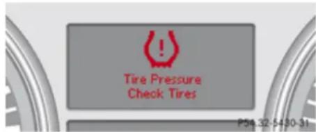
text_image
Tire Pressure Check Tires P54 32-5430-31Example illustration
Restarting the TPMS
Warning!
It is the driver's responsibility to set the reference values to the recommended cold tire inflation pressure. Underinflated tires affect the ability to steer or brake the vehicle. You might lose control over the vehicle.
When you restart the TPMS, the system sets new reference values for each tire.
The TPMS must be restarted when you have adjusted the tire inflation pressure to a new level (e.g. because of different load or driving conditions). The TPMS is then recalibrated to the current tire inflation pressures. Restart the TPMS after adjusting the tire inflation pressure to the inflation pressure recommended for the vehicle operating condition. Tire pressure should only be adjusted on cold tires. Observe the recommended tire inflation pressure on the Tire and Loading Information placard on the driver's door B-pillar. Some vehicles may have supplemental tire pressure information for driving at high speeds or for vehicle loads less than the maximum loaded vehicle condition. If such information is provided, it can be found on the inside of the fuel filler flap.
Using the Tire and Loading Information placard on the driver's door B-pillar ( page 275) or, if available, the supplemental tire inflation pressure information on the inside of the fuel filler flap ( page 265), make sure the tire inflation pressure of all four tires is correct.
▶ Switch on the ignition.
▶ Press button or on the multifunction steering wheel repeatedly
Operation
Tires and wheels
until the standard display appears in the multifunction display (▷ page 152).
▶ Press button △ or ▽ on the multifunction steering wheel repeatedly until the following message appears in the multifunction display:
Tire Pressure Monitor Active Menu: R-Button
▶ Press the reset button (▷ page 147).
The following message appears in the multifunction display: Restart tire pressure monitor?
▶ If you wish to confirm: Press button + .
The following message appears in the multifunction display: Tire Pressure Monitor Restarted
After driving a few minutes the system verifies that the current tire inflation pressures are within the system's specified range. Afterwards, the current tire inflation
pressures are accepted as reference values and then monitored.
▶ If you wish to cancel: Press button —.
MOExtended system
The MOExtended system allows you to continue driving your vehicle even if there is a total loss of pressure in one or more tires.
You may only use the MOExtended system in conjunction with the Run Flat Indicator ( page 282) or the TPMS ( page 283).
i Vehicles with MOExtended system are not factory-equipped with a TIREFIT kit. When retrofitting with tires that do not have run-flat characteristics, e.g. winter tires, you should also equip your vehicle with a TIREFIT kit. TIREFIT kits are available at any authorized Mercedes-Benz Center.
For information on driving in case of pressure loss in one or more tires (emergency mode), see the "Practical Hints" section (> page 403).
Tire labeling
Besides tire name (sales designation) and manufacturer name, a number of markings can be found on a tire.
Following are some explanations for the markings on your vehicle's tires:
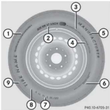
text_image
JOINTY AT ANION MANUFACTURER 1 2 3 4 5 6 7 8 9 P40.10-4705-31① Uniform Tire Quality Grading Standards (▷ page 292)
② DOT, Tire Identification Number (▷ page 290)
③ Maximum tire load ( page 291)
④ Maximum tire inflation pressure (▷ page 291)
Operation
Tires and wheels
⑤ Manufacturer
⑥ Tire ply material (▷ page 293)
⑦ Tire size designation, load and speed rating (▷ page 287)
⑧ Load identification (▷ page 289)
⑨ Tire name
For illustration purposes only. Actual data on tires are specific to each vehicle and may vary from data shown in above illustration.
For more information, see “Rims and tires” (▷ page 425).
Tire size designation, load and speed rating
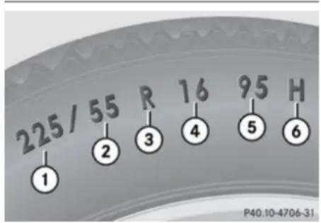
text_image
225 / 55 R 16 95 H ① ② ③ ④ ⑤ ⑥ P40.10-4706-31① Tire width
② Aspect ratio in %
③ Radial tire code
④ Rim diameter
⑤ Tire load rating
⑥ Tire speed rating
For illustration purposes only. Actual data on tires are specific to each vehicle and may vary from data shown in above illustration.
General: Depending on the design standards used, the tire size molded into the sidewall may have no letter or a letter preceding the tire size designation.
No letter preceding the size designation (as illustrated above): Passenger car tire based on European design standards.
Letter "P" preceding the size designation: Passenger car tire based on U.S. design standards.
Letter “LT” preceding the size designation: Light Truck tire based on U.S. design standards.
Letter “T” preceding the size designation: Temporary spare tires which are high pressure compact spares designed for temporary emergency use only.
Tire width
Tire width ① indicates the nominal tire width in millimeters.
Aspect ratio
Aspect ratio ② is the dimensional relationship between tire section height and section width and is expressed in percentage. The aspect ratio is arrived at by dividing section height by section width.
Tire code
Tire code ③ indicates the tire construction type. The "R" stands for radial tire type. Letter "D" means diagonal or bias ply construction; letter "B" means belted-bias ply construction.
At the tire manufacturer's option, any tire with a speed capability above 149 mph (240 km/h) can include a "ZR" in the size designation (for example: 245/40 ZR 18). For additional information, see "Tire speed rating" (▷ page 288).
Rim diameter
Rim diameter ④ is the diameter of the bead seat, not the diameter of the rim edge. The rim diameter is indicated in inches (in).
Operation
Tires and wheels
Tire load rating

Warning!
The tire load rating must always be at least half of the GAWR of your vehicle.
Otherwise, tire failure may be the result which may cause an accident and/or serious injury to you or others.
Always replace rims and tires with the same designation, manufacturer and type as shown on the original part.

Warning!
Do not overload the tires by exceeding the specified load limit as indicated on the Tire and Loading Information placard on the driver's door B-pillar. Overloading the tires can overheat them, possibly causing a blowout. Overloading the tires can also result in handling or steering problems, or brake failure.
Tire load rating ⑤ is a numerical code associated with the maximum load a tire can support.
For example, a load rating of 91 corresponds to a maximum load of 1356 lb (615 kg) the tire is designed to support. See also
"Maximum tire load" (▷ page 291) where the
maximum load associated with the load index is indicated in kilograms and lbs.
For additional information on tire load rating, see "Load identification" (▷ page 289).
Tire speed rating

Warning!
Even when permitted by law, never operate a vehicle at speeds greater than the maximum speed rating of the tires.
Exceeding the maximum speed for which tires are rated can lead to sudden tire failure, causing loss of vehicle control and possibly resulting in an accident and/or serious personal injury and possible death, for you and for others.
Regardless of the tire speed rating, local speed limits should be obeyed. Use prudent driving speeds appropriate to prevailing conditions.
Tire speed rating ⑥ indicates the approved maximum speed for the tire.
Summer tires
| Index Speed rating |
| Q up to 100 mph (160 km/h) |
| R up to 106 mph (170 km/h) |
| S up to 112 mph (180 km/h) |
| T up to 118 mph (190 km/h) |
| H up to 130 mph (210 km/h) |
| V up to 149 mph (240 km/h) |
| W up to 168 mph (270 km/h) |
| Y up to 186 mph (300 km/h) |
| ZR...Y up to 186 mph (300 km/h) |
| ZR...(..Y) above 186 mph (300 km/h) |
| ZR above 149 mph (240 km/h) |
- At the tire manufacturer's option, any tire with a speed capability above 149 mph (240 km/h) can include a "ZR" in the size designation (for example: 245/40 ZR18). To determine the maximum speed
Operation
Tires and wheels
capability of the tire, the service description for the tire must be referred to. The service description is comprised of tire load rating ⑤ and tire speed rating ⑥. If your tire includes “ZR” in the size designation and no service description is given, the tire manufacturer must be consulted for the maximum speed capability.
If a service description is given, the speed capability is limited by the speed symbol in the service description. Example: 245/40 ZR18 97Y. In this example, "97Y" is the service description. The letter "Y" designates the speed rating and the speed capability of the tire is limited to 186 mph (300 km/h).
- Any tire with a speed capability above 186 mph (300 km/h) must include a “ZR” in the size designation AND the service description must be placed in parenthesis. Example: 275/40 ZR 18 (99Y). The “(Y)” speed rating in parenthesis designates the maximum speed capability of the tire as being above 186 mph (300 km/h). Consult the tire manufacturer for the actual maximum permissible speed of the tire.
All-season and winter tires
| Index Speed rating | |
| Q M+S13 | up to 100 mph (160 km/h) |
| T M+S13 | up to 118 mph (190 km/h) |
| H M+S13 | up to 130 mph (210 km/h) |
| V M+S13 | up to 149 mph (240 km/h) |
Not all M+S rated tires provide special winter performance. Make sure the tires you use show M+S and the mountain/snowflake marking on the tire sidewall. These tires meet specific snow traction performance requirements of the Rubber Manufacturers Association (RMA) and the Rubber Association of Canada (RAC) and have been designed specifically for use in snow conditions.
An electronic speed limiter prevents your vehicle from exceeding a speed of 130 mph (210 km/h).
The factory equipped tires on your vehicle may have a tire speed rating above the maximum speed permitted by the electronic speed limiter.
Make sure your tires have the required tire speed rating as specified for your vehicle in the “Technical data” section ( page 425), for example when purchasing new tires. If you are uncertain about the correct reading of the information given on a tire’s sidewall, any authorized Mercedes-Benz Center will be glad to assist you.
Load identification
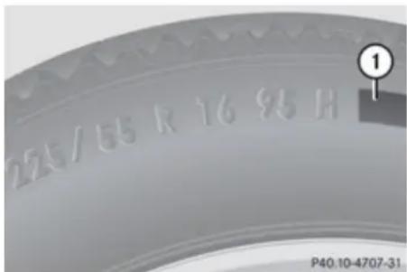
text_image
275/65 R 16 95 H P40.10-4707-31① Load identification
For illustration purposes only. Actual data on tires are specific to each vehicle and may vary from data shown in above illustration.
Operation
Tires and wheels
In addition to tire load rating, special load identification ① may be molded into the tire sidewall following the letter designating the tire speed rating ⑥ (▶ page 287).
- No specification given: absence of any text (like in above example) indicates a standard load (SL) tire.
- XL or Extra Load: designates an extra load (or reinforced) tire.
• Light Load: designates a light load tire.
• C, D, E: designates load range associated with the maximum load a tire can carry at a specified pressure.
DOT, Tire Identification Number (TIN)
U.S. tire regulations require each new tire manufacturer or tire retreader to mold a TIN into or onto a sidewall of each tire produced. The TIN is a unique identifier which facilitates efforts by tire manufactures to notify purchasers in recall situations or other safety matters concerning tires and gives purchasers the means to easily identify such tires.
The TIN is comprised of "Manufacturer's identification mark", "Tire size", "Tire type code" and "Date of manufacture".
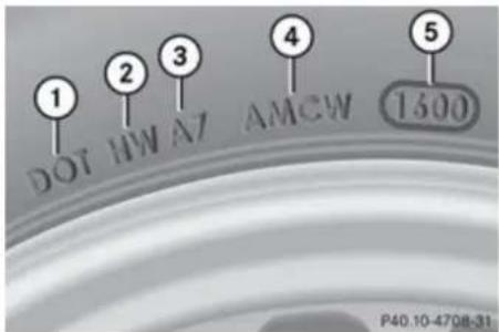
text_image
1 DOT HW AT AMCW 4 5 1500 P40.10-4708-31① DOT
② Manufacturer's identification mark
③ Tire size
④ Tire type code (at the option of the tire manufacturer)
⑤ Date of manufacture
For illustration purposes only. Actual data on tires are specific to each vehicle and may vary from data shown in above illustration.
DOT (Department of Transportation)
Tire branding symbol ① denotes that the tire meets requirements of the U.S. Department of Transportation.
Manufacturer's identification mark
Manufacturer's identification mark ② denotes the tire manufacturer.
New tires have a mark with two symbols.
Retreaded tires have a mark with four symbols. For more information on retreaded tires, see (▷ page 272).
Tire size
Code ③ indicates the tire size.
Tire type code
Tire type code ④ may, at the option of the manufacturer, be used as a descriptive code for identifying significant characteristics of the tire.
Date of manufacture
The date of manufacture ⑤ identifies the week and year of manufacture.
The first two figures identify the week, starting with "01" to represent the first full week of the calendar year. The second two figures represent the year.
For example, "3202" represents the 32nd week of 2002.
Operation
Tires and wheels
Maximum tire load

Warning!
Do not overload the tires by exceeding the specified load limit as indicated on the Tire and Loading Information placard on the driver's door B-pillar. Overloading the tires can overheat them, possibly causing a blowout. Overloading the tires can also result in handling or steering problems, or brake failure.
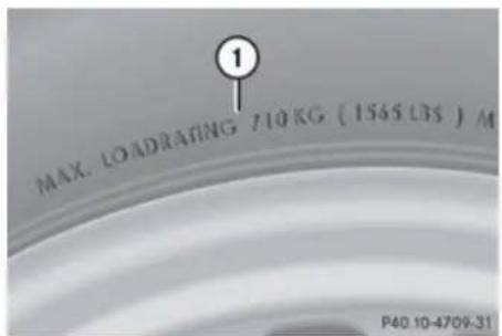
text_image
MAX. LOADRATING 710 KG (1565 LBS) M P40.10-4709-31① Maximum tire load rating
For illustration purposes only. Actual data on tires are specific to each vehicle and may vary from data shown in above illustration.
The maximum tire load is the maximum weight the tires are designed to support.
For more information on tire load rating, see (▷ page 288).
For information on calculating total and cargo load capacities, see ( page 277).
Maximum tire inflation pressure
Warning!
Never exceed the maximum tire inflation pressure. Follow recommended tire inflation pressures.
Do not underinflate tires. Underinflated tires wear excessively and/or unevenly, adversely affect handling and fuel economy, and are more likely to fail from being overheated.
Do not overinflate tires. Overinflated tires can adversely affect handling and ride comfort, wear unevenly, increase stopping distance, and result in sudden deflation (blowout) because they are more likely to become punctured or damaged by road debris, potholes etc.
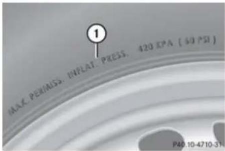
text_image
1 MAX. PERMISS, INPEAT. PRESS. 420 KPA (60 PSI) P40.10-4710-31① Maximum permissible tire inflation pressure
For illustration purposes only. Actual data on tires are specific to each vehicle and may vary from data shown in above illustration.
This is the maximum permissible tire inflation pressure for the tire.
Always follow the recommended tire inflation pressure ( page 279) for proper tire inflation.
Operation
Tires and wheels
Uniform Tire Quality Grading Standards
The Uniform Tire Quality Grading is a U.S. Government requirement designed to give drivers consistent and reliable information regarding tire performance. Tire manufacturers are required to grade tires based on three performance factors: treadwear, traction, and temperature resistance. Although not a Government of Canada requirement, all tires made for sale in North America have these grades branded on the sidewall.
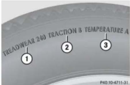
text_image
TREADWEAR 240 TRACTION & TEMPERATURE A ① ② ③ P40.10-4711-31① Treadwear
② Traction
③ Temperature resistance
For illustration purposes only. Actual data on tires are specific to each vehicle and may vary from data shown in above illustration.
Quality grades can be found, where applicable, on the tire sidewall between tread shoulder and maximum section width. For example:
Treadwear Traction Temperature
200 AA A
All passenger car tires must conform to federal safety requirements in addition to these grades.
Treadwear
The treadwear grade is a comparative rating based on the wear rate of the tire when tested under controlled conditions on a specified U.S. Government test course. For example, a tire graded 150 would wear one and one-half ( 1^-1/_2 ) times as well on the government course as a tire graded 100.
The relative performance of tires depends upon the actual conditions of their use, however, and may depart significantly from the norm due to variations in driving habits, service practices and differences in road characteristics and climate.
Traction

Warning!
The traction grade assigned to this tire is based on straight-ahead braking traction tests, and does not include acceleration, cornering, hydroplaning, or peak traction characteristics.
The traction grades, from highest to lowest, are AA, A, B, and C. Those grades represent the tire's ability to stop on wet pavement as measured under controlled conditions on specified government test surfaces of asphalt and concrete. A tire marked C may have poor traction performance.

Warning!
If ice has formed on the road, tire traction will be substantially reduced. Under such weather conditions, drive, steer and brake with extreme caution.
The safe speed on a wet, snow covered or icy road is always lower than on a dry road. You should pay particular attention to the condition of the road whenever the outside temperature is close to the freezing point.
Operation
Tires and wheels
Mercedes-Benz recommends winter tires ( page 297) with a minimum tread depth of approximately ^1/_6 in (4 mm) on all four wheels for the winter season to ensure normal balanced handling characteristics. On packed snow, they can reduce your stopping distance compared to summer tires. Stopping distance, however, is still considerably greater than when the road is not covered with snow or ice. Exercise appropriate caution.
Avoid spinning of a drive wheel. This may cause serious damage to the drivetrain which is not covered by the Mercedes-Benz Limited Warranty.
Temperature

Warning!
The temperature grade for this tire is established for a tire that is properly inflated and not overloaded. Excessive speed, underinflation, or excessive loading, either separately or in combination, can cause excessive heat build-up and possible tire failure.
The temperature grades are A (the highest), B, and C, representing the tire's resistance to the generation of heat and its ability to dissipate heat when tested under controlled conditions on a specified indoor laboratory test wheel. Sustained high temperature can cause the material of the tire to degenerate and reduce tire life, and excessive temperature can lead to sudden tire failure. The grade C corresponds to a level of performance which all passenger car tires must meet under the Federal Motor Vehicle Safety Standard No. 109. Grades B and A represent higher levels of performance on the laboratory test wheel than the minimum required by law.
Tire ply material
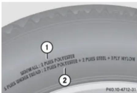
text_image
SIDEWALL: 2 PUES POLYESTER 5 PUES UNDER TREAD : 2 PUES POLYESTER + 2 PUES STEEL + 1PLY NYLON P40.10-4712-31① Plies in sidewall
② Plies under tread
For illustration purposes only. Actual data on tires are specific to each vehicle and may vary from data shown in above illustration.
This marking tells you about the type of cord and number of plies in the sidewall and under the tread.
Tire and loading terminology
Accessory weight
The combined weight (in excess of those standard items which may be replaced) of automatic transmission, power steering, power brakes, power windows, power seats, radio, and heater, to the extent that these items are available as factory-installed equipment (whether installed or not).
Air pressure
The amount of air inside the tire pressing outward on each square inch of the tire. Air pressure is expressed in pounds per square inch (psi), or kilopascal (kPa) or bar.
Operation
Tires and wheels
Aspect ratio
Dimensional relationship between tire section height and section width expressed in percentage.
Bar
Another metric unit for air pressure. There are 14.5038 pounds per square inch (psi) to 1 bar; there are 100 kilopascals (kPa) to 1 bar.
Bead
The tire bead contains steel wires wrapped by steel cords that hold the tire onto the rim.
Cold tire inflation pressure
Tire inflation pressure when your vehicle has been sitting for at least 3 hours or driven no more than 1 mile (1.6 km).
Curb weight
The weight of a motor vehicle with standard equipment including the maximum capacity of fuel, oil, and coolant, and, if so equipped, air conditioning and additional optional equipment, but without passengers and cargo.
DOT (Department of Transportation)
A tire branding symbol which denotes the tire meets requirements of the U.S. Department of Transportation.
GAWR (Gross Axle Weight Rating)
The GAWR is the maximum permissible axle weight. The gross vehicle weight on each axle must never exceed the GAWR for the front and rear axle indicated on the certification label located on the driver's door B-pillar.
GTW (Gross Trailer Weight)
The GTW is the weight of the trailer plus the weight of all cargo, equipment, luggage etc. loaded on the trailer.
GVW (Gross Vehicle Weight)
The GVW comprises the weight of the vehicle including fuel, tools, spare wheel, installed accessories, passengers and cargo and, if applicable, trailer tongue load. The GVW must never exceed the GVWR indicated on the certification label located on the driver's door B-pillar.
GVWR (Gross Vehicle Weight Rating)
This is the maximum permissible vehicle weight of the fully loaded vehicle (weight of the vehicle including all options, passengers, fuel, and cargo and, if applicable, trailer tongue load). It is indicated on certification label located on the driver's door B-pillar.
Kilopascal (kPa)
The metric unit for air pressure. There are 6.9 kPa to 1 psi; another metric unit for air pressure is bar. There are 100 kilopascals (kPa) to 1 bar.
Maximum load rating
The maximum load in kilograms and pounds that can be carried by the tire.
Maximum loaded vehicle weight
The sum of curb weight, accessory weight, total load limit, and production options weight.
Operation
Tires and wheels
Maximum permissible tire inflation pressure
This number is the greatest amount of air pressure that should ever be put in the tire.
Normal occupant weight
The number of occupants the vehicle is designed to seat, multiplied by 68 kilograms (150 lb).
Occupant distribution
The distribution of occupants in a vehicle at their designated seating positions.
Production options weight
The combined weight of those installed regular production options weighing over 5 lbs (2.3 kilograms) in excess of those standard items which they replace, not previously considered in curb weight or accessory weight, including heavy duty brakes, ride levelers, roof rack, heavy duty battery, and special trim.
PSI (Pounds per square inch)
A standard unit of measure for air pressure.
Recommended tire inflation pressure
The recommended tire inflation pressure for normal driving conditions is listed on the Tire and Loading Information placard located on the driver's door B-pillar and provides best handling, tread life and riding comfort. If so equipped, supplemental information pertaining to special driving situations can be found on the tire inflation pressure label on the inside of the fuel filler flap.
Rim
A metal support for a tire or a tire and tube assembly upon which the tire beads are seated.
Sidewall
The portion of a tire between the tread and the bead.
TIN (Tire Identification Number)
Unique identifier which facilitates efforts by tire manufacturers to notify purchasers in
recall situations or other safety matters concerning tires and gives purchasers the means to easily identify such tires. The TIN is comprised of “Manufacturer’s identification mark”, “Tire size”, “Tire type code” and “Date of manufacture”.
Tire load rating
Numerical code associated with the maximum load a tire can support.
Tire ply composition and material used
This indicates the number of plies or the number of layers of rubber-coated fabric in the tire tread and sidewall. Tire manufacturers also must indicate the ply materials in the tire and sidewall, which include steel, nylon, polyester, and others.
Tire speed rating
Part of tire designation; indicates the speed range for which a tire is approved.
Total load limit
Rated cargo and luggage load plus 68 kilograms (150 lb) times the vehicle's designated seating capacity.
Operation
Tires and wheels
Traction
Force exerted by the vehicle on the road via the tires. The amount of grip provided.
Tread
The portion of a tire that comes into contact with the road.
Treadwear indicators
Narrow bands, sometimes called "wear bars" that show across the tread of a tire when only 1/16 in (1.6 mm) of tread remains.
TWR (Tongue Weight Rating)
Maximum permissible weight on trailer tongue.
Uniform Tire Quality Grading Standards
A tire information system that provides consumers with ratings for a tire's traction, temperature and treadwear. Ratings are determined by tire manufacturers using U.S. government testing procedures. The ratings are molded into the sidewall of the tire.
Vehicle maximum load on the tire
Load on an individual tire that is determined by distributing to each axle its share of the maximum loaded vehicle weight and dividing it by two.
Rotating tires
Warning!
Rotate front and rear wheels only if the tires are of the same dimension.
If your vehicle is equipped with mixed-size tires (different tire dimensions front vs. rear), tire rotation is not possible.
Warning!
Have the tightening torque checked after changing a wheel. The wheels could come loose if they are not tightened to a torque of 110 lb-ft (150 Nm).
Only use genuine Mercedes-Benz wheel bolts specified for your vehicle's rims.
Tire rotation can be performed on vehicles with tires of the same dimension all around. If your vehicle is equipped with tires of the same dimension all around, tires can be rotated, observing a front-to-rear rotation pattern that will maintain the intended
rotation (spinning) direction of the tire (▷ page 275).
In some cases, such as when your vehicle is equipped with mixed-size tires (different tire dimension front vs. rear), tire rotation is not possible.
If applicable to your vehicle's tire configuration, tires can be rotated according to the tire manufacturer's recommended intervals in the tire manufacturer's warranty pamphlet located in your vehicle literature portfolio. If none is available, tires should be rotated every 3000 to 6000 miles (5000 to 10000 km), or sooner if necessary, according to the degree of tire wear. The same rotation (spinning) direction must be maintained.
Rotate tires before the characteristic tire wear pattern becomes visible (shoulder wear on front tires and tread center wear on rear tires).
Thoroughly clean the mounting face of wheels and brake disks, i.e. the inner side of the wheels/tires, during each rotation. Check for and ensure proper tire inflation pressure.
For information on wheel change, see "Flat tire" (▷ page 397).
Operation
Winter driving
Winter driving
General information
Have your vehicle winterized at an authorized Mercedes-Benz Center.
Winter tires
Warning!
Winter tires with a tread depth of less than ^1/_6 in (4 mm) must be replaced. They are no longer suitable for winter operation.
Warning!
If you use your spare wheel when winter tires are fitted on the other wheels, be aware that the difference in tire characteristics may very well impair turning stability and that overall driving stability may be reduced. Adapt your driving style accordingly.
Have the spare wheel replaced by regular road wheel with a winter tire at the nearest authorized Mercedes-Benz Center.
Always use winter tires at temperatures below 45^ F ( 7^ C) and whenever wintry road conditions prevail. Not all M+S rated tires provide special winter performance. Make
sure the tires you use show the mountain/snowflake ⚠ marking on the tire sidewall.
These tires meet specific snow traction performance requirements of the Rubber Manufacturers Association (RMA) and the Rubber Association of Canada (RAC) and have been designed specifically for use in snow conditions. Use of winter tires is the only way to achieve the maximum effectiveness of your vehicle's driving safety systems such as the ABS and the ESP® in winter operation.
For safe handling, make sure all mounted winter tires are of the same make and have the same tread design.
For information on winter tires for your vehicle model, see the "Technical data" section ( page 425).
Always observe the speed rating of the winter tires installed on your vehicle. If the maximum speed for which your tires are rated is below the speed rating of your vehicle, you must place a notice to this effect where it will be seen by the driver. Such notices are available at your tire dealer or any authorized Mercedes-Benz Center.
Snow chains
! Vehicles with Adaptive Damping System (ADS):
When driving with snow chains, do not select SPORT mode as this may result in damage to your vehicle.
! Some tire sizes do not leave adequate clearance for snow chains. To help avoid serious damage to your vehicle or tires, make sure the use of snow chains is permissible as specified in the “Technical data” section of this Operator’s Manual.
Snow chains should only be driven on snow-covered roads at speeds not to exceed 30 mph (50 km/h). Remove chains as soon as possible when driving on roads without snow.
Observe the following guidelines when using snow chains:
- Use of snow chains is not permissible with all wheel/tire combinations (▷ page 425).
- Use snow chains in pairs and on rear wheels only. Follow the manufacturer's mounting instructions.
! If snow chains are mounted to the front wheels, they may scrape against the body
Operation
Winter driving
or axle components. The tires or the vehicle could be damaged as a result.
- Only use snow chains that are approved by Mercedes-Benz. Any authorized Mercedes-Benz Center will be glad to advise you on this subject.
- Use of snow chains may be prohibited depending on location. Always check local and state laws before installing snow chains.
- Do not use snow chains on the spare wheel.
When driving with snow chains, you may wish to switch off the ESP® (▷ page 77) before setting the vehicle in motion. This will improve the vehicle's traction.
Winter driving instructions
Warning!
If the vehicle becomes stuck in snow, make sure snow is kept clear of the exhaust pipe and from around the vehicle with the engine running. Otherwise, deadly carbon monoxide (CO) gases may enter vehicle interior resulting in unconsciousness and death.
To assure sufficient fresh air ventilation, open a window slightly on the side of the vehicle not facing the wind.
Warning!
The outside temperature indicator is not designed to serve as an ice-warning device and is therefore unsuitable for that purpose.
Indicated temperatures just above the freezing point do not guarantee that the road surface is free of ice. The road may still be icy, especially in wooded areas or on bridges.
Warning!
On slippery road surfaces, never downshift in order to obtain braking action. This could result in drive wheel slip and reduced
vehicle control. Your vehicle's ABS will not prevent this type of control loss.
Do not engage the transfer case in position LOW when driving on ice or packed snow. At speeds below 18 mph (30 km/h) vehicle steering is adversely affected by the Off-road ABS.
The most important rule for slippery or icy roads is to drive sensibly and to avoid abrupt acceleration, braking and steering maneuvers. Do not use the cruise control system under such conditions.
When the vehicle is in danger of skidding, shift the automatic transmission to neutral position N. Try to keep the vehicle under control by corrective steering action.
For information on driving with snow chains, see "Snow chains" (▷ page 297).
Road salts and chemicals can adversely affect braking efficiency. Increased pedal force may become necessary to produce the normal brake effect.
Depressing the brake pedal periodically when traveling at length on salt-strewn roads can bring road-salt-impaired braking efficiency back to normal.
If the vehicle is parked after being driven on salt-treated roads, the braking efficiency
Operation
Driving instructions
should be tested as soon as possible after driving is resumed.

Warning!
Make sure not to endanger any other road users when carrying out these braking maneuvers.
Driving instructions
Drive sensibly – save fuel
To save fuel you should:
- Keep tires at the recommended inflation pressures.
- Remove unnecessary loads.
- Remove carriers when not in use.
- Remove the crossbars when not in use.
- Allow engine to warm up under low load use.
- Avoid frequent acceleration and deceleration.
- Have all maintenance work performed at the intervals specified in the Maintenance Booklet and as required by the Maintenance system. Contact an authorized Mercedes-Benz Center.
Fuel consumption is also increased by driving in cold weather, in stop-and-go traffic, on short trips and in mountainous areas.
Drinking and driving

Warning!
Drinking and driving and/or taking drugs and driving are very dangerous combinations. Even a small amount of alcohol or drugs can affect your reflexes, perceptions and judgment.
The possibility of a serious or even fatal accident are greatly increased when you drink or take drugs and drive.
Do not drink or take drugs and drive or allow anyone to drive who has been drinking or taking drugs.
Pedals

Warning!
Make sure absolutely no objects are obstructing the pedals' range of movement. Keep the driver's footwell clear of all obstacles. If there are any floormats or carpets in the footwell, make sure that the pedals still have sufficient clearance. During sudden driving or braking maneuvers, the objects could get caught between the pedals. You could then no
▶▶
Operation
Driving instructions
longer brake or accelerate. This could lead to accidents and injury.
Power assistance

Warning!
There is no power assistance for the steering and the service brake when the engine is not running.
Steering and braking requires significantly more effort and you could lose control of the vehicle and cause an accident as a result.
Do not turn off the engine while the vehicle is in motion.
Brakes
Downhill grades
When driving down long and steep grades, relieve the load on the brakes by shifting into a lower gear to use the engine's braking power. This helps prevent overheating of the brakes and reduces wear.
When using the engine's braking power, a drive wheel may not spin for an extended period of time, e.g. on slippery road surfaces. This may cause serious damage to the drivetrain which is not covered by the Mercedes-Benz Limited Warranty.
Continuous or hard braking

Warning!
Resting your foot on the brake pedal will cause excessive and premature wear of the brake pads.
It can also result in the brakes overheating, thereby significantly reducing their effectiveness. It may not be possible to stop the vehicle in sufficient time to avoid an accident.
After hard braking, it is advisable to drive on for some time, rather than immediately park, so that the air stream will cool down the brakes faster.
Wet roads

Warning!
After driving in heavy rain for some time without applying the brakes or through water deep enough to wet brake components, the first braking action may be somewhat reduced and increased pedal pressure may be necessary to obtain expected brake effect. Maintain a safe distance from vehicles in front.
To help prevent brake disk corrosion after driving on wet or salt-covered roads, it is advisable to brake the vehicle with considerable force prior to parking. The heat generated serves to dry the brakes.
Salt-covered roads

Warning!
A layer of salt on the brake discs and the brake linings may cause a delay in the braking effect, resulting in a significantly
Operation
Driving instructions
increased braking distance, which could lead to an accident.
To avoid this danger, you should:
- occasionally brake carefully when you are driving on salt-covered roads, so that any layer of salt that may have built up on the brake discs and the brake linings is removed without putting other road users at risk
- maintain a greater distance to the vehicle ahead and drive with particular care
- carefully apply the brakes at the end of a trip and immediately after commencing a new trip, so that salt residues are removed from the brake disc
Brake service
! The brake fluid level in the reservoir may be too low if the brake warning lamp in the instrument cluster comes on and an acoustic warning sounds although the parking brake is released. Observe additional messages in the multifunction display that may appear.
Brake pad wear or a leak in the system may be the reason for low brake fluid in the reservoir.
Have the brake system inspected immediately. Contact an authorized Mercedes-Benz Center.
All checks and service work on the brake system should be carried out by qualified technicians only. Contact an authorized Mercedes-Benz Center.
Only install brake pads and use brake fluid recommended by Mercedes-Benz.
Warning!
If other than recommended brake pads are installed, or other than recommended brake fluid is used, the braking properties of the vehicle can be degraded to an extent that safe braking is substantially impaired. This could result in an accident.
! Only conduct operational or performance tests on a two-axle dynamometer. If such tests are necessary, contact an authorized Mercedes-Benz Center. You could otherwise seriously damage the brake system or the transfer case which is not covered by the Mercedes-Benz Limited Warranty.
Because the ESP® operates automatically, the engine and ignition must be shut off (SmartKey in starter switch position 0 or 1 or KEYLESS-GO start/stop button in position 0 or 1) when the parking brake is being tested on a brake test dynamometer. Such testing should be no longer than 10 seconds.
Active braking action through the ESP ^® may otherwise seriously damage the brake system which is not covered by the Mercedes-Benz Limited Warranty.
If your brake system is normally only subjected to moderate loads, you should occasionally test the effectiveness of the brakes by applying above-normal braking pressure at higher speeds. This will also enhance the grip of the brake pads.
Warning!
Make sure not to endanger any other road users when carrying out these braking maneuvers.
Refer to the description of the Brake Assist System (BAS) (▷ page 77).
Operation
Driving instructions
Parking brake
When driving on wet roads or dirt covered surfaces, road salt and/or dirt can get into the parking brake.
To prevent corrosion and a reduction in the braking power of the parking brake, observe the following:
From time to time, lightly engage the parking brake before driving off.
▶ Drive a distance of approximately 110 yds (100 m) at a maximum speed of 12 mph (20 km/h).

Warning!
While performing this procedure please assure that the vehicle is stopped before applying the parking brake. Otherwise the rear wheels could lock up. You could lose control of the vehicle and cause an accident. In addition, the vehicle's brake lights do not light up when the parking brake is engaged. Make sure not to endanger any other road users when you engage the parking brake.
Driving off
Warm up the engine smoothly. Do not place full load on the engine until the operating temperature has been reached.
When driving off on a slippery surface, do not allow a drive wheel to spin for an extended period with the ESP® switched off. Doing so may cause serious damage to the drivetrain which is not covered by the Mercedes-Benz Limited Warranty.
! Simultaneously depressing the accelerator pedal and applying the brakes reduces engine performance and causes premature brake and drivetrain wear which is not covered by the Mercedes-Benz Limited Warranty.
Hydroplaning
Depending on the depth of the water layer on the road, hydroplaning may occur, even at low speeds and with new tires.
▶ Reduce vehicle speed.
▶ Avoid track grooves in the road.
▶ Brakes cautiously in the rain.
Standing water
! Do not drive through flooded areas. Before driving through water, determine its depth.
If you must drive through standing water, drive slowly to prevent water from entering the passenger compartment or the engine compartment. Water in these areas could cause damage to electrical components or wiring of the engine or transmission, or could result in water being ingested by the engine through the air intake causing severe internal engine damage. Any such damage is not covered by the Mercedes-Benz Limited Warranty.
i Select the raised level (▷ page 186) before driving through standing water.
Operation
Driving instructions
For more information, see "Driving through water" (▷ page 306).
Off-road driving

Warning!
Do not load items on the crossbars. It may cause instability during some maneuvers which could result in an accident.
Drive slowly in unknown terrain. This will make it easier to recognize unexpected obstacles and avoid damage to the vehicle.
To help avoid the vehicle rolling over, never turn it around on steep inclines. If the vehicle cannot complete the attempted climb, back it down in reverse gear.
Do not drive along the side of a slope. The vehicle might otherwise rollover. If in doing so the vehicle begins to show a tendency to roll, immediately steer into a line of gravity (straight up or downhill).
Never let the vehicle roll backwards in idle. You may lose control of the vehicle if you use only the service brake. For information on driving downhill, see "Driving downhill".
Warning!
Sand, dirt, mud and other material having friction property can cause exceptional wear and tear as well as brake failure. Have the brakes checked for dirt build-up and cleaned. There is otherwise a risk that full braking power may not be available in an emergency.
Warning!
Please be aware that by raising the vehicle level, the center of gravity also rises. Therefore, always ensure that the vehicle level is as low as possible. With higher ride height the ESP ^® may activate earlier in certain situations.
Read this chapter carefully before you begin off-road travel.
Familiarize yourself with the vehicle characteristics and gear changing before you attempt any difficult terrain off-road driving. We recommend that you start out with easy off-road travel.
Special driving features for off-road driving
The following driving features are available for specific kind of operation:
- Off-road ABS (▷ page 77)
- Off-road ESP® (▷ page 80)
- Off-road 4-ETS (▷ page 78)
• Hill start assist system (▷ page 139) - LOW RANGE mode (▷ page 142)
• Differential locks (▷ page 144) - Downhill Speed Regulation (DSR) (▷ page 182)
- Off-road driving program (Vehicles without enhanced off-road package) (▷ page 185)
• Air suspension program (▷ page 185)
Off-road driving rules
- Engage the off-road driving program
(▷ page 185) or LOW RANGE mode
(▷ page 142) before driving under off-road conditions. - If necessary, activate differential locks (▷ page 144).
Operation
Driving instructions
- Make sure you select a vehicle level (▷ page 186) appropriate to the topographical conditions. Always make sure the vehicle has enough ground clearance.
- Fasten items being carried as securely as possible (▷ page 227).
- Always navigate gradients with the engine on and with the transmission engaged in a gear. Switch on the DSR (▶ page 182) to help maintain a preset speed.
! Observe the following during off-road driving:
- Keep doors, tailgate, windows, and tilt/sliding sunroof closed whenever driving off-road.
- Adjust vehicle speed to condition of terrain. The more uneven, rutty and steeper the terrain, the lower the speed should be. Drive through water slowly at an even speed, avoiding a bow wave.
-
Be especially careful when driving in unknown territory. It may be necessary to get out of the vehicle and scout the path you intend to take.
-
Watch out for obstacles, such as rocks, holes, tree stumps and ruts.
- Before driving through water, determine its depth.
- Do not stop vehicle while immersed in water, and do not shut off the engine.
- In sandy soil, drive at a steady speed as allowed by conditions. This helps overcome the vehicle rolling resistance and reduces the likelihood of the vehicle sinking into the ground.
- Do not initiate jumps with the vehicle. It interrupts the forward momentum of the vehicle.
• Always drive onto slopes with the engine running and the vehicle in gear. - Do not shift automatic transmission into neutral position N.
Warning!
Do not reduce the tire inflation pressure before driving through sand. However, if you do so, remember to correct the tire inflation pressure before continuing your trip. Driving with reduced tire inflation pressure increases the risk of losing control of the vehicle and rolling over.
Checklist before off-road driving
Engine oil level
- Check the engine oil level (▷ page 269). Only with a proper oil level can the vehicle obtain a trouble-free oil supply, even on steep gradients.
! If the engine oil level warning lamp comes on while driving, stop the vehicle in a safe location or as soon at is safe to do so. Check the engine oil level.
The engine oil level warnings should not be ignored. Extended driving with the symbol displayed could result in serious engine damage that is not covered by the Mercedes-Benz Limited Warranty.
Tires
- Check the tread depth and maintain specified tire inflation pressure (a placard with the recommended tire inflation pressures is located on the driver's door B-pillar (▷ page 276)).
- Check tires for possible damage and remove foreign objects.
- Replace missing valve caps.
Operation
Driving instructions
Rims
- Dented or bent rims can cause tire inflation pressure loss and damage the tire beads. For this reason, check and, if necessary, change rims before driving off-road.
Vehicle tool kit
- Check if the vehicle jack (▷ page 329) is functional.
• In all cases take the vehicle tool kit, a strong tow rope, a shovel and a small plank (to put under the vehicle jack on sandy soil) with you.
Driving in steep terrain
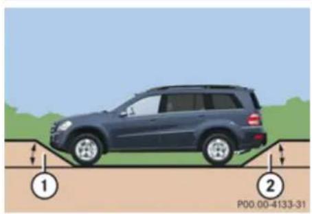
text_image
P00.00-4133-31Slope angle
① Overhang angle, front
② Overhang angle, rear
| Vehicles with air suspension program | 1 | 2 |
| Raised level 32° 26° | ||
| Highway 27° 21° |
| Vehicles with enhanced off-road package | 1 | 2 |
| Off-road-level 3 33° 27° | ||
| Off-road-level 2 32° 26° | ||
| Off-road-level 1 28° 23° | ||
| Highway 27° 21° |
- Comply with the warnings (▷ page 303) and rules for off-road driving (▷ page 303).
- Driving on embankments, slopes and other steep inclines should only be done straight up or downhill, i.e. in the line of gravity. Maximum vehicle climbing ability is a 100% grade which is equivalent to a slope angle of 45°. Keep in mind that the
climbing ability of the vehicle depends on terrain conditions.
- Shift automatic transmission into gear range 1 (▷ page 139).
- Drive slowly.
- Avoid excessive engine speeds – drive with moderate engine speeds (max. 3000 rpm).
- Utilize the engine's braking power when descending a slope, observe the engine speed (do not overrev the engine). Apply the service brake as needed.
For maximum engine speed, see "Instrument cluster" (▷ page 32) and see "Engine" (▷ page 423).
- Check the brakes after a lengthy downgrade drive.
Warning!
Never turn the vehicle around on steep inclines. The vehicle might roll over. If the vehicle cannot complete the attempted climb, back it down in reverse gear.
i The hill start assist system supports you when driving uphill. For more information, see “Hill start assist system” (▷ page 139).
Operation
Driving instructions
Traction in steep terrain
The maximum vehicle climbing ability is a 100% grade which is equivalent to a slope angle of 45^ . Keep in mind that the climbing ability of the vehicle depends on terrain conditions.
Be easy on the accelerator and watch for continuous wheel traction when driving in steep terrain.
The 4-ETS helps greatly when starting out on a steep incline when the front wheels have then the tendency to slip due to the weight shifting towards the rear axle.
The 4-ETS recognizes the situation and limits the torque for the front wheels by braking them.
Simultaneously the torque for the rear wheels is increased.
i Vehicles with enhanced off-road package are equipped with automatic locks for the center and rear axle differential to improve vehicle traction.
Driving across a hilltop
Decelerate just ahead of a hilltop (do not shift automatic transmission into neutral position
N), to prevent the vehicle from speeding up too much after climbing a hill.
Use the momentum of the vehicle to drive across the hilltop.
After climbing a hill, driving in this manner prevents the vehicle from:
- losing ground contact when cresting hills
- losing its forward momentum
• speeding up too much after climbing the hill
Driving downhill
- Drive slowly.
- Do not drive at an angle to the incline. Steer into the line of gravity and drive with the front wheels pointing straight downhill. Otherwise, the vehicle may slide sideways off the path and roll over.
- Shift automatic transmission into gear range 1 ( page 139).
- On steep inclines, use the Downhill Speed Regulation (▷ page 182).
- Utilize the engine's braking power to reduce vehicle speed.
If this is insufficient, apply the brakes gently. Make sure the vehicle is moving in the line of gravity.
- Check the brakes after a lengthy downgrade drive.
The special Off-road ABS (▷ page 77) setting allows for precise and brief (cyclical) blocking of the front wheels, permitting them to dig into loose ground. Remember that, when stopped, the front wheels slide across a surface and thus lose their ability to steer the vehicle.
Driving through water
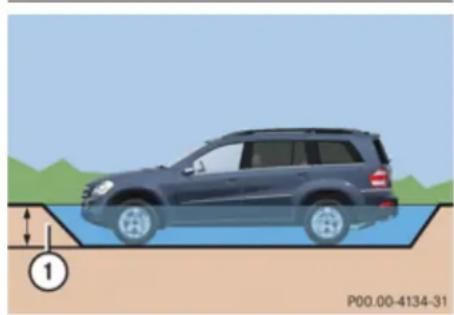
natural_image
Illustration of a car on a wet surface with a water channel and a numbered marker (no text or symbols on the vehicle itself)① Fording depth
Operation
Driving instructions
| Vehicles with air suspension program (raised level) | 1 |
| Vehicles with BlueTEC | 14.00 in (35 cm) |
| All other vehicles 20.00 in (50 cm) | |
| Vehicles with enhanced off-road package | 1 |
| Off-road 1 level 20.00 in (50 cm) | |
| Off-road 2 level 20.00 in (50 cm) | |
| Off-road 3 level 23.60 in (60 cm) |
- Before driving through water, determine its depth.
! The water depth must not exceed the respective value listed in the table. The ground under the water might not be firm which could result the water being deeper than expected when driving the vehicle
through it. Please note that the water level is correspondingly lower for flowing water.
- Select the highest vehicle level possible (▷ page 186).
- Switch to off-road driving program (▷ page 185) or LOW RANGE mode (▷ page 142) before driving through water.
- Shift automatic transmission into gear range 1 or 2 (▷ page 139).
- Avoid high engine speeds.
- Enter and leave the water only at a shallow spot, driving at walking speed.
! Never accelerate before driving into the water. The bow wave could force water into the engine and auxiliary equipment, thus damaging them.
- Drive through the water slowly and at a constant speed.
- Do not stop vehicle while immersed in water, and do not shut off the engine.
! Do not open any of the vehicle's doors while driving through water. Water could otherwise enter the vehicle interior and damage the vehicle's electronics, as well as the interior equipment.
- There is a very high level of driving resistance in water. The surface is slippery and may not be firm, making pulling away in water difficult and dangerous.
• Make sure that only small bow waves are formed when driving the vehicle through water. - Clean mud off the tire tread after driving through water.
- To dry the brakes, apply pressure to the brake pedal several times while driving after leaving the water.
Crossing obstacles
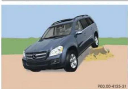
natural_image
Illustration of a blue SUV driving on a dirt road with grassy background (no text or symbols)! Obstacles can damage the vehicle underbody or suspension components. If
Operation
Driving instructions
possible use the assistance of a second person outside the vehicle to scout the path you intend to take and check for adequate ground clearance when you cross obstacles with your vehicle. The person assisting you outside the vehicle should always be a safe distance away from the vehicle and positioned so that he or she cannot get hurt in case of any unexpected vehicle movement.
After off-road driving or crossing obstacles, inspect vehicle for any damage, especially vehicle underbody and suspension components. Failure to do so can adversely affect the vehicle's future performance, including increased chance of an accident.
When driving over tree stumps, big rocks and other obstacles, observe the following rules:
- Make sure the off-road driving program (▷ page 185) or if equipped the LOW RANGE mode (▷ page 142) is switched on.
- Avoid high engine speeds.
- Shift automatic transmission into gear range 1 (▷ page 139).
- Check the vehicle clearance before crossing obstacles. - Cross obstacles (e.g. tree stumps or big rocks) very slowly by aiming one of the front wheels at the center of the obstacle, and repeat same with the rear wheel.
! Special attention is needed when you cross obstacles on a steep incline. The vehicle could slide sideways as a result of its possible slanted position which in turn may result in the vehicle tipping or rolling over.
Driving on sand
Warning!
Do not reduce the tire inflation pressure before driving through sand. However, if you do so, remember to correct the tire inflation pressure before continuing your trip. Driving with reduced tire inflation pressure increases the risk of losing control of the vehicle and rolling over.
When driving on sand, observe the following rules:
- Set the raised level (▷ page 186).
-
Avoid high engine speeds.
-
Shift automatic transmission into a gear range that is appropriate for the terrain.
- In sandy soil, drive at a steady speed as conditions permit. This helps overcome the vehicle rolling resistance and reduce the likelihood of the vehicle sinking into the ground.
- Drive in tracks of other vehicles if they are not too deep and you have sufficient clearance.
Ruts
A number of off-road tracks or other byways have deep ruts which can cause the underbody to come in contact with the ground.
- Make sure the off-road driving program (▷ page 185) or, if equipped, the LOW RANGE mode (▷ page 142) is switched on.
- Set the raised level (> page 186).
Operation
Driving instructions
! Check that the ruts are not too deep and your vehicle's clearance is sufficient. Otherwise:
- your vehicle may be damaged
- the underbody of the vehicle may come in contact with the ground and you may get stuck
- Avoid high engine speeds.
- Shift automatic transmission into gear range 1 (▷ page 139).
- Drive next to the ruts rather than through them if at all possible.
- If the ruts are too deep to drive in, drive with one side of the vehicle on the grassy center strip if the route permits.
Returning from off-road driving

Warning!
If you feel a sudden significant vibration or ride disturbance, or you suspect that possible damage to your vehicle has occurred, you should turn on the hazard warning flashers, carefully slow down, and drive with caution to an area which is a safe distance from the road.
Inspect the tires and the vehicle underbody for possible damage. If the vehicle or tires appear unsafe, have the vehicle towed to the nearest authorized Mercedes-Benz Center or tire dealer for repairs.
Off-road driving increases strain on the vehicle.
We recommend that you inspect the vehicle for possible damage after each off-road trip. Recognizing any damage and a subsequent timely repair reduces the chance of a possible breakdown or accident later on.
Proceed as follows:
- Switch off the off-road driving program (▷ page 185) or the LOW RANGE mode (▷ page 142).
- Switch off the DSR (▷ page 182).
- Set the differential locks to AUTO (▷ page 145).
- Lower the vehicle back to a level suitable for road conditions, e.g. highway/high-speed level (▷ page 186).
- Clean all exterior lamps and check for possible damage.
-
Clean the front and rear license plate.
-
Remove excessive dirt from tires, wheels, wheel housings, and underbody. For instance, after driving in mud, clean the radiator, chassis, engine, brakes, and wheels from extreme dirt using a strong jet of water.
- Check tires for possible damage.
- Inspect vehicle underbody, oil pan, brake hoses, etc., as well as vehicle underbody for possible damage.
- Check for brush or branches caught in the underbody.
Brush or branches could increase the possibility of a fire, as well as cut fuel and/or brake lines, puncture rubber bellows of the axles or drive shafts.
• After continued operation in mud, sand, water or other dirty conditions clean the brake discs, wheels, brake pads and check and clean axle joints.
- Conduct a brake test.
Operation
Driving instructions
Trailer towing

Warning!
Failure to use proper equipment and driving technique can result in a loss of vehicle control when towing a trailer.
Improper towing or failure to follow the instructions in this manual can result in vehicle damage and/or serious personal injury. Follow the guidelines below carefully to assure safe trailer operation.
Contact an authorized Mercedes-Benz Center should you require an explanation of information contained in this manual.
Trailer hitch
- Only install a trailer hitch receiver approved for your vehicle.
For information on availability and installation, contact an authorized Mercedes-Benz Center.
- The bumpers on your vehicle are not designed for use with clamp-type hitches.
Do not attach rental hitches or other bumper-type hitches to them.
• To reduce the possibility of damage, remove the hitch ball adapter from the receiver when not in use.
Electrical connections
The vehicle is prewired to accept the seven-wire harness included in the Mercedes-Benz approved trailer hitch receiver kit.
A four-pole conversion plug is available from your authorized Mercedes-Benz Center as a spare part.
For further information, contact an authorized Mercedes-Benz Center.
Vehicle and trailer weights and ratings
The Gross Trailer Weight (GTW) is the weight of the trailer plus the weight of all cargo, equipment, luggage, etc. loaded on the trailer. The maximum permissible gross trailer weight to be towed: 7 500 lb (3402 kg). Trailer Tongue Weight Rating (TWR) is the maximum permissible weight on the trailer tongue: 600 lb (272 kg) limit for Mercedes-Benz approved hitch receiver.
Loading a trailer
- When loading a trailer, you should observe that neither the permissible GTW, nor the Gross Vehicle Weight Rating (GVWR) are exceeded. The GVWR is indicated on the certification label located on the driver's door B-pillar (▷ page 275).
Maximum permissible values are listed on the safety compliance certification labels for the vehicle and for the trailer to be towed.
The lowest value listed must be selected when determining how the vehicle and trailer are loaded.
- The Tongue Weight (TW) at the hitch ball must be added to the Gross Vehicle Weight (GVW) to prevent exceeding your Mercedes-Benz tow vehicle's rear Gross Axle Weight Rating (GAWR). The GVW and GAWR are indicated on the certification label located on the driver's door B-pillar (▶ page 275).
Mercedes-Benz recommend loading the trailer in such a manner that it has a TW between 8% and 15% of the GTW.
i Maximum trailer weight ratings are calculated assuming the vehicle, plus
Operation
Driving instructions
driver. The weight of other accessories, passengers and cargo will reduce the maximum trailer weight and TW your vehicle can tow.
Checking weights of vehicle and trailer
- To assure that the towing vehicle and trailer are in compliance with the maximum permissible weight limits, have the loaded rig (towing vehicle including driver, passengers and cargo, trailer fully loaded) weighed on a commercial scale.
- Check the vehicle's front and rear Gross Axle Weight (GAW), the Gross Trailer Weight (GTW) and Tongue Weight (TW). The values as measured must not exceed the weight limits listed under "Vehicle and trailer weights and ratings" (▶ page 310).
Coupling a trailer

Warning!
While you are coupling or decoupling a trailer, make sure nobody locks or unlocks the vehicle and/or opens or closes doors or the tailgate.
The vehicle's level could change and you could endanger yourself and/or others as a result.
Make sure that you do not operate the ADS button or the vehicle level control system when coupling/decoupling the trailer.
Observe maximum permitted trailer dimensions (width and length).
Most states and all Canadian provinces require
-
safety chains between the towing vehicle and the trailer
The chains should be criss-crossed under the trailer tongue. They must be attached to the hitch receiver, and not to the vehicle's bumper or axle.
Make sure to leave enough slack in the chains to permit turning corners. -
a separate brake system at various trailer weights
- a break-away switch on trailers with a separate brake system. Check with your local state laws for specific requirements.
The switch activates the trailer brakes in the possible event that the trailer might separate from the tow vehicle.
! Do not connect a trailer brake system (if trailer is so equipped) directly to the vehicle's hydraulic brake system, as your vehicle is equipped with antilock brakes. If you do, neither the vehicle's brakes nor the trailer's brakes will function properly.
i The provided vehicle electrical wiring harness for trailer towing has a brake signal wire for hook-up to a brake controller.
▶ Make sure the automatic transmission is in park position P (▷ page 136).
▶ Engage the parking brake for the vehicle (▷ page 133).
▶ Start the engine (▷ page 128).
▶ Set the vehicle level to highway (▷ page 186).
▶ Vehicles with ADS: Set the ADS to AUTO or COMF (▷ page 185).
▶ Turn off the engine (▷ page 133).
▶ Close all doors and the tailgate.
▶ Attach the trailer.
▶ Plug in all electrical connectors.
Operation
Driving instructions
When you are towing a trailer, the vehicle level always remains in the highway setting. The following applies additionally when towing a trailer:
- The vehicle is lowered to the highway level when it reaches a speed of 5 mph (8 km/h) if not set to highway level.
• The highspeed level is not available.
The restrictions that apply to towing also apply when using accessories that are connected to the trailer power socket, such as a bicycle rack.
Towing a trailer
There are many different laws, including speed limit restrictions, having to do with trailer towing. Make sure your rig will be legal, not only for where you reside, but also for where you will be driving. A good source for this information can be the police or local authorities.
Note the following, when driving with a trailer:
- In order to gain skill and an understanding of the vehicle's behavior, you should
practice turning, stopping and backing up in an area which is free from traffic.
• Before you start driving check the
- trailer hitch
- break-away switch
- safety chains
- electrical connections
- lighting
-
tires
-
Adjust the mirrors (▷ page 111) to permit unobstructed view beyond rear of trailer.
- If the trailer has electric brakes, start your vehicle and trailer moving slowly, and then apply only the trailer brake controller by hand to make sure the brakes are working properly.
• Always secure items in the trailer to prevent load shifts while driving. - When towing a trailer, check occasionally to make sure the load is secure, and that lighting and trailer brakes (if so equipped) are functioning properly.
• Take into consideration that when towing a trailer, the handling characteristics are
different and less stable from those when operating the vehicle without a trailer. It is important to avoid sudden maneuvers.
- The vehicle and trailer combination is heavier, and therefore is limited in acceleration and climbing ability, and requires longer stopping distances.
It is more prone to reacting to cross wind gusts, and requires more sensitive steering input.
• If possible, do not brake abruptly, but rather engage the brake slightly at first to permit the trailer to activate its brake. Then increase the braking force.
! If the trailer should begin to sway, reduce the vehicle's speed immediately. Do not attempt to straighten out the tow vehicle and trailer by increasing the speed. - If the transmission shifts between gears on inclines repeatedly, shift to a lower gear range manually (▷ page 139). Select 4, 3, 2 or 1.
A lower gear and reduction of speed reduces the chance of engine overloading and/or overheating.
- On very steep inclines, not manageable with automatic transmission in gear range
Operation
Driving instructions
1, switch on off-road driving program ( page 185) or LOW RANGE mode ( page 142).
- When going down an incline, shift into a lower gear and use the engine's braking effect.
Avoid riding the brakes, thus overheating the vehicle and trailer brakes (if so equipped).
- If the engine coolant rises to an extremely high temperature when the air conditioning is on, turn off the air conditioning system.
Engine coolant heat can be additionally vented by opening the windows, switching the climate control fan speed to high and setting the temperature control to the maximum.
- Extreme care must be exercised since your vehicle with a trailer will require additional passing distance ahead than when driving without a trailer.
Because your vehicle and trailer is longer than your vehicle alone, you will also need to go much farther ahead of the passed vehicle before you can return to your lane.
Decoupling the trailer
Warning!
While you are coupling or decoupling a trailer, make sure nobody locks or unlocks the vehicle and/or opens or closes doors or the tailgate.
The vehicle's level could change and you could endanger yourself and/or others as a result.
Make sure that you do not operate the ADS button or the vehicle level control system when coupling/decoupling the trailer.
▶ Make sure the automatic transmission is in park position P (▷ page 136).
▶ Engage the parking brake for the vehicle (▷ page 133).
▶ Start the engine (▷ page 128).
▶ Close all doors and the tailgate.
▶ Engage the parking brake for the trailer.
Warning!
As soon as you disconnect the electrical connection between the trailer and the vehicle, the vehicle will lower. To help avoid personal injury, make sure no one is near the wheel housing or underneath the
vehicle before the electrical connection is disconnected.
When you decouple the trailer, the vehicle is temporarily raised because the springs are relieved of load. Be especially careful during this process, as you could otherwise injure yourself and/or others. Make sure that any persons remaining in the vehicle do not press the switches for vehicle level control or the ADS.
▶ Disconnect all electrical plug connectors.
▶ Decouple the trailer.
▶ Make sure that the trailer coupling is free of load.
▶ Turn off the engine (▷ page 133).
Operation
Driving instructions
Driving abroad
If you plan to drive the vehicle outside the U.S. or Canada, you should request dealer network information for your destination from any authorized Mercedes-Benz Center.
Control and operation of radio transmitter
Safety notes

Warning!
Please do not forget that your primary responsibility is to drive the vehicle safely. Only operate the COMAND (Cockpit Management and Data system), radio or telephone ^14 if road, weather and traffic conditions permit. Otherwise, you may not be able to observe traffic conditions and could endanger yourself and others. Bear in mind that at a speed of just 30 mph (approximately 50 km/h), your vehicle is covering a distance of 44 feet (approximately 14 m) every second.
Telephones and two-way radios

Warning!
Never operate radio transmitters equipped with a built-in or attached antenna, such as a portable telephone or a citizens band unit, from inside the vehicle while the engine is running. Doing so could lead to a malfunction of the vehicle's electronic system, possibly resulting in an accident and/or serious personal injury. Radio transmitters should only be used inside the vehicle if they are connected to an antenna that is installed on the outside of the vehicle.

Warning!
Please do not forget that your primary responsibility is to drive the vehicle. A driver's attention to the road must always be his/her primary focus when driving. For your safety and the safety of others, we recommend that you pull over to a safe location and stop before placing or taking a telephone call.
If you choose to use the telephone ^15 while driving, please use the hands-free device
and only use the telephone when road, weather and traffic conditions permit. Some jurisdictions prohibit the driver from using a mobile telephone while driving a vehicle.
Only operate the COMAND ^15 (Cockpit Management and Data System) if road, weather and traffic conditions permit. Bear in mind that at a speed of just 30 mph (approximately 50 km/h), your vehicle is covering a distance of 44 feet (approximately 14 m) every second.
Refer to the radio transmitter operation instructions regarding use of an external antenna.
Operation
Maintenance
Emission control
Certain systems of the engine serve to keep the toxic components of the exhaust gases within permissible limits required by law.
These systems will function properly only when maintained strictly according to factory specifications. Any adjustments on the engine should, therefore, be carried out only by qualified Mercedes-Benz Center authorized technicians.
Engine adjustments should not be altered in any way. Moreover, the specified service procedures must be carried out regularly according to Mercedes-Benz servicing requirements. For details refer to the Maintenance Booklet.
Warning!
Inhalation of exhaust gas is hazardous to your health. All exhaust gas contains carbon monoxide (CO), and inhaling it can cause unconsciousness and possible death.
Do not run the engine in confined areas (such as a garage) which are not properly ventilated. If you think that exhaust gas fumes are entering the vehicle while driving, have the cause determined and
corrected immediately. If you must drive under these conditions, drive only with at least one window fully open at all times.
Maintenance
Notes
The Maintenance System in your vehicle tracks distance driven and the time elapsed since the last maintenance service, calculates other maintenance service work required, and calls for the next maintenance service accordingly.
We strongly recommend that you have your vehicle serviced at an authorized Mercedes-Benz Center, in accordance with the Maintenance Booklet at the times called for by the maintenance service indicator.
Failure to have the vehicle maintained in accordance with the Maintenance Booklet and maintenance service indicator at the designated times/mileage will result in vehicle damage not covered by the Mercedes-Benz Limited Warranty.
Operation
Maintenance
Maintenance service indicator message
The maintenance service indicator message will notify you when the next maintenance service is due.
Starting approximately 1 month before the next maintenance service is due, one of the following messages will appear in the multifunction display while you are driving or when you switch on the ignition (example service A):
Service A In XXXX Miles (km)
text_image
Service A In 2730 Miles PS4.12-2567-31The maintenance services will be indicated by showing a service type A through type H in the multifunction display. Types A through H are classified based on estimated time needed to perform the maintenance service, ranging: from Service A
(approximately 1 hour)
to Service H
(approximately 8 hours)
Refer to Maintenance Booklet for a listing of maintenance services and intervals they need to be performed at.
Clearing the maintenance service indicator message
The maintenance service indicator message is cleared automatically
• after approximately 10 seconds when you switch on the ignition
• after approximately 10 seconds when reaching the service threshold while driving
• after approximately 30 seconds, once the suggested maintenance service term has passed
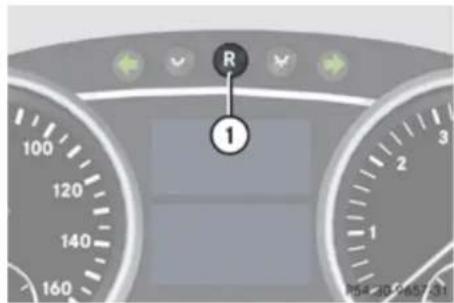
text_image
R 1① Reset button
▶ Clearing the maintenance service indicator message manually: Press reset button ① on the instrument cluster. The standard display appears in the multifunction display.
Maintenance service term exceeded
If you have exceeded the suggested maintenance service term, you will see the following message in the multifunction display:
Service A Exceeded By XXXXX Miles (Km)
Service A Exceeded By XXX Days
Service A Exceeded By X Day
Operation
Maintenance
In addition, a signal sounds when the message appears.
Any authorized Mercedes-Benz Center will reset the maintenance service indicator following a completed maintenance service.
Calling up the maintenance service indicator display
The menu overview can be found on (▷ page 151).
You can call up the maintenance service indicator display at any time to check when the next maintenance service is due.
▶ Switch on the ignition.
▶ Press button or on the multifunction steering wheel repeatedly until the standard display (▶ page 152) appears in the multifunction display.
▶ Press button 📋 or 🐘 on the multifunction steering wheel until the maintenance service indicator display with the service symbol 🔍 and the maintenance service deadline appears in the multifunction display.
If the battery is disconnected, the days of disconnection will not be included in the
count shown by the maintenance service indicator. To arrive at the true maintenance service deadline, you will need to subtract these days from the days shown in the maintenance service indicator message or maintenance service indicator display. Do not confuse the maintenance service indicator with the engine oil level indicator
Resetting the maintenance service indicator
In the event that the maintenance service on your vehicle is not carried out at an authorized Mercedes-Benz Center, you can have the maintenance service indicator reset.
The automotive maintenance facility carrying out the maintenance service will find the information for resetting the maintenance service indicator in the maintenance-relevant literature for your vehicle.
Such literature is available from any authorized Mercedes-Benz Center or directly from Mercedes-Benz.
If the maintenance service indicator was inadvertently reset, have an authorized Mercedes-Benz Center correct it.
Only reset if the proper maintenance service has been performed. Resetting the system without performing the proper maintenance service as called for by the maintenance service indicator will result in engine damage and/or other vehicle damage not covered by the Mercedes-Benz Limited Warranty.
Operation
Vehicle care
Vehicle care
Cleaning and care of the vehicle
Notes
Regular and proper care will help to maintain the value of your vehicle.

Warning!
Many cleaning products can be hazardous. Some are poisonous, others are flammable. Always follow the instructions on the particular container. Always open your vehicle's doors or windows when cleaning the inside.
Never use fluids or solvents that are not designed for cleaning your vehicle. Always lock away cleaning products and keep them out of reach of children.
! When cleaning the vehicle, do not use scouring agents. Never apply strong force and only use a soft, wet cloth or sponge. Otherwise you may scratch or damage the surface to be cleaned.
While in operation, even while parked, your vehicle is subjected to varying external influences which, if gone unchecked, can
attack the paintwork as well as the vehicle underbody and cause lasting damage.
Such damage is caused not only by extreme and varying climatic conditions, but also by:
• Air pollution
- Road salt
• Tar
• Gravel and stone chipping
To avoid paint damage, you should immediately remove:
- Grease and oil
- Fuel
- Coolant
- Brake fluid
- Bird droppings
- Insects
- Tree resins etc.
Frequent washing reduces and/or eliminates the aggressiveness and potency of the above adverse influences.
More frequent washings are necessary to deal with unfavorable conditions:
- near the ocean
- in industrial areas (smoke, exhaust emissions)
• during winter operation
You should check your vehicle from time to time for stone chipping or other damage. Any damage should be repaired as soon as possible to prevent corrosion.
In doing so, do not neglect the underbody of the vehicle. A prerequisite for a thorough check is a washing of the underbody followed by a thorough inspection. Damaged areas need to be re-undercoated.
Your vehicle has been treated at the factory with a wax-base rustproofing in the body cavities which will last for the lifetime of the vehicle. Post-production treatment is neither necessary nor recommended by Mercedes-Benz because of the possibility of incompatibility between materials used in the production process and others applied later. We have selected vehicle-care products and compiled recommendations which are specially matched to our vehicles and which always reflect the latest technology. You can obtain Mercedes-Benz approved vehicle-care
Operation
Vehicle care
products at an authorized Mercedes-Benz Center.
Scratches, corrosive deposits, corrosion or damage due to negligent or incorrect care cannot always be removed or repaired with the vehicle-care products recommended here. In such cases it is best to seek aid at an authorized Mercedes-Benz Center.
The following topics deal with the cleaning and care of your vehicle and give important “how-to” information as well as references to Mercedes-Benz approved vehicle-care products.
Power washer
! Follow the instructions provided by the power washer manufacturer on maintaining a distance between the vehicle and the nozzle of the power washer.
Never use a round nozzle to power-wash tires. The intense jet of water can result in damage to the tire.
Always replace a damaged tire.
Always keep the jet of water moving across the surface. Do not aim directly at electrical parts, electrical connectors, seals, or other rubber parts.
i Vehicles with KEYLESS-GO: If a door handle is hit by a strong jet of water, and a SmartKey is within approximately 3 ft (1 m) of the vehicle, it could be inadvertently locked or unlocked.
Tar stains
Quickly remove tar stains before they dry and become more difficult to remove. A tar remover is recommended.
Paintwork, painted body components
! Affixing stickers, magnets, adhesive tape or similar materials to painted body components may damage the paintwork.
Mercedes-Benz approved Paint Care should be applied when water drops on the paint surface do not “bead up”. This should normally be done every 3 to 5 months, depending on the climate and washing detergent used.
Mercedes-Benz approved Paint Cleaner should be applied if the paint surface shows signs of embedded dirt (i.e. loss of gloss).
Do not apply any of these products or wax if your vehicle is parked in the sun or if the hood is still hot.
▶ Use the appropriate MB-Touch-Up Stick for quick and provisional repairs of minor paint damage (i.e. chips from stones, vehicle doors, etc.).
Engine cleaning
Prior to cleaning the engine compartment, make sure to protect electrical components and connectors from contact with water and cleaning agents.
Corrosion protection, such as MB Anticorrosion Wax should be applied to the engine compartment after every engine cleaning. Before applying, all control linkage bushings and joints should be lubricated. The poly-V-belt and all pulleys should be protected from any wax.
Vehicle washing
In the winter, thoroughly remove all traces of road salt as soon as possible.
When washing the vehicle underbody, do not forget to clean the inner sides of the wheels.
i Vehicles with KEYLESS-GO: If a door handle is hit by a strong jet of water, and a SmartKey is within
▶▶
Operation
Vehicle care
approximately 3 ft (1 m) of the vehicle, it could be inadvertently locked or unlocked.
Hand-wash
▶ Do not use hot water or wash your vehicle in direct sunlight.
▶ Only use a soft, wet cloth or sponge to clean the vehicle.
▶ Only use a mild vehicle wash detergent, such as Mercedes-Benz approved Car Shampoo.
▶ Thoroughly spray the vehicle with a diffused jet of water.
▶ Do not spray directly towards the ventilation intake.
▶ Use plenty of water and rinse the sponge and chamois frequently.
- Rinse with clean water and thoroughly dry with a chamois.
Do not allow cleaning agents to dry on the finish.
Automatic car wash
You can have your vehicle washed in an automatic car wash from the start. Brushless car washes are preferable.
To protect the filter system, activate the air recirculation mode using button 📄 on the climate control panel.
! Do not clean your vehicle in an automatic touchless car wash which uses caustic spray. Caustic spray will damage the paint or ornamental moldings.
If the vehicle is very dirty, prewash it before running it through the automatic car wash.
! Make sure the combination switch is set to wiper setting 0. Otherwise, the rain sensor could activate and cause the wipers to move unintentionally. This may lead to vehicle damage.
Due to the width of the vehicle, fold in exterior rear view mirrors prior to running the vehicle through an automatic car wash to prevent damage to the mirrors.
When taking the vehicle through an automatic conveyor-type car wash:
Make sure the automatic transmission remains in neutral position N. Observe instructions, see "Remaining in neutral position N" (▷ page 136).
When leaving the automatic car wash, make sure the mirrors are folded out.
After running the vehicle through an automatic car wash, wipe any wax off of the windshield and the wiper blade inserts. This will prevent smears and reduce wiping noise which can be caused by residual wax on the windshield.
Ornamental moldings
For regular cleaning and care of ornamental moldings, use a damp cloth.
! Do not use chrome cleaner on ornamental moldings. Although ornamental moldings may have chrome appearance, they could be made of anodized aluminum that will be damaged when cleaned with chrome cleaner. Instead, use a damp cloth to clean those ornamental moldings.
For very dirty ornamental moldings of which you are sure are chrome-plated, use a chrome cleaner. If in doubt whether an ornamental molding is chrome-plated, contact an authorized Mercedes-Benz Center.
Operation
Vehicle care
Headlamps, brake lamps, tail lamps, side markers, turn signal lenses
▶ Use a mild vehicle wash detergent, such as Mercedes-Benz approved Car Shampoo, with plenty of water.
! Only use window cleaning solutions that are suitable for plastic lamp lenses. Window cleaning solutions which are not suitable may damage the plastic lamp lenses of the headlamps. Therefore, do not use abrasives, solvents or cleaners that contain solvents.
Cleaning the Distronic system sensor cover
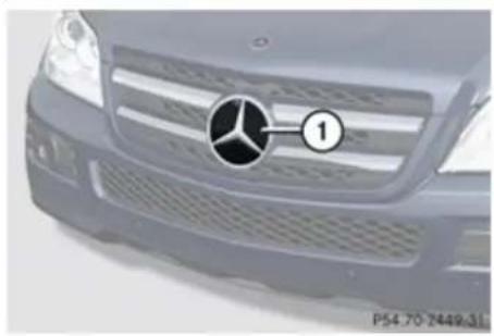
natural_image
Front view of a Mercedes-Benz car grille with logo and number 1 (no text or symbols on the grille itself)① Distronic system sensor cover
▶ Switch off the ignition.
▶ Only clean sensor cover ① by hand.
▶ Use a mild vehicle wash detergent, such as Mercedes-Benz approved Car Shampoo, with plenty of water and a non-scratching cloth to clean sensor cover ①.
▶ Restart the engine after cleaning sensor cover ①.
Cleaning the Parktronic system sensors
Parktronic system sensors are located in the front and rear bumper.
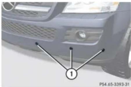
natural_image
Front view of a car with visible grille and headlights, marked with number 1 (no text or symbols on the car itself)① Parktronic system sensors in front bumper
▶ Only clean sensors ① by hand.
▶ Use a mild vehicle wash detergent, such as Mercedes-Benz approved Car Shampoo, with plenty of water and a soft, non-scratching cloth to clean sensors ① on the bumpers.
! Applying strong pressure may damage the sensor covers.
Cleaning the rear view camera lens

natural_image
Front view of a car rear bumper with a close-up inset showing a component labeled '1' (no text or symbols on the main body)① Camera lens
▶ Only use clean water and a soft, non-scratching cloth to clean camera lens ①.
Be careful not to apply wax to camera lens ① when waxing the vehicle. If necessary,
Operation
Vehicle care
remove the wax using the Mercedes-Benz approved Car Shampoo with plenty of water.
! Do not clean the camera and the area around the camera
- with a high-pressure cleaner
- with a dry cloth and strong pressure
- with aggressive cleaning agents
You could otherwise damage the camera.
Cleaning the windows and the wiper blades
! Never open the hood when the wiper arms are folded forward.
Warning!
For safety reasons, switch off wipers and remove SmartKey from starter switch (vehicles with KEYLESS-GO: Make sure the vehicle's on-board electronics have status 0) before cleaning the windshield and/or the wiper blades. Otherwise, the wiper motor could suddenly turn on and cause injury.
! Do not pull on the wiper blade inserts. They could tear.
▶ Fold the wiper arms forward until they snap into place.
▶ Clean the windshield and the wiper blade inserts with a clean cloth and mild detergent solution.
▶ Use a soft, clean cloth and a mild window cleaning solution on all outside and inside glass surfaces.
An automotive glass cleaner is recommended.
! Fold the windshield wiper arms back onto the windshield before turning the SmartKey in the starter switch or pressing the KEYLESS-GO start/stop button (vehicles with KEYLESS-GO).
Hold on to the wiper when folding the wiper arm back. If released, the force of the impact from the tensioning spring could crack the windshield.
! To clean the window interior, do not use a dry cloth, abrasives, solvents or cleaners containing solvents. Do not touch the inside of the front, rear or side windows and the power tilt/sliding sunroof or rear panorama roof with hard objects such as an ice scraper or ring. Doing so may
damage the windows or the sunroof/panorama roof.
Light alloy wheels
If possible, clean wheels once a week.
▶ Use Mercedes-Benz approved Wheel Care, a soft bristle brush and a strong spray of water for cleaning the light alloy wheels.
! Only use acid-free cleaning materials. Acid may cause corrosion or damage the clear coat.
! The vehicle should not be parked for an extended period of time immediately after it has been cleaned, especially not after the wheel rims have been cleaned with wheel rim cleaner. Wheel rim cleaners can lead to increased corrosion of the brake disks and brake pads. Non-approved wheel cleaners may also damage the wheel paint if the vehicle is not driven after cleaning.
Therefore, the vehicle's brake system should always be warmed-up before it is parked after cleaning. Drive your vehicle for several minutes to allow the brakes to dry. When applying Mercedes-Benz approved Tire Care and Mercedes-Benz approved
Operation
Vehicle care
Wheel Care products, take care not to spray them on the brake disks.
Plastic and rubber parts
▶ Use a gentle dishwashing detergent or mild detergent for delicate fabrics as a washing solution.
Wipe with a cloth moistened in a lukewarm solution.
The surface may temporarily change color. If this is the case, wait for it to dry.

Warning!
Do not use cleaners or cockpit care sprays containing solvents to clean the cockpit or the steering wheel. Cleaners containing solvents will make the surface porous and vehicle occupants could suffer serious injuries from plastic parts coming loose in the event of air bag deployment.

Do not use oil, wax or scouring agents.
Otherwise you may scratch or damage the surface.
Hard plastic trim items
▶ Use Mercedes-Benz approved Interior Care on a soft, lint-free cloth and apply with light pressure.
COMAND display
You must switch off the COMAND display and allow it to cool prior to cleaning.
! Do not use any liquids or cleaning agents. These can damage or even destroy the audio display screen.
▶ Use a standard microfiber cloth and apply with light pressure.
Steering wheel
▶ Wipe with a damp cloth and dry thoroughly or clean with Mercedes-Benz approved Leather Care.
Carpets
▶ Use Mercedes-Benz approved Carpet and Fabric Care for cleaning the carpets.
Headliner
▶ Use a soft bristle brush or a dry-shampoo cleaner in case of excessive dirt.
Seat belts
▶ Only use clear, lukewarm water and soap.
! The seat belts must not be treated with chemical cleaning agents. Do not dry the seat belts at temperatures above 176°F (80°C) or in direct sunlight.

Warning!
Do not bleach or dye seat belts as this may severely weaken them. In a crash they may not be able to provide adequate protection.
Upholstery
Using aftermarket seat covers or wearing clothing that have the tendency to give off coloring (e.g. when wet, etc.) may cause the upholstery to become permanently discolored. By lining the seats with a proper intermediate cover, contact-discoloration will be prevented.
Operation
Vehicle care

Warning!
Only use seat or head restraint covers which have been tested and approved by Mercedes-Benz for your vehicle model. Using other seat or head restraint covers may interfere with or prevent
- deployment of the front side impact air bags
- deployment of the rear side impact air bags
- activation of the active head restraints Contact an authorized Mercedes-Benz Center for availability.
Leather upholstery
Please note that leather upholstery is a natural product and is therefore subject to a natural aging process. Leather upholstery may also react to certain ambient influences such as high humidity or high temperature by showing wrinkles for example.
▶ Wipe leather upholstery with a damp cloth and dry thoroughly or clean with Mercedes-Benz approved Leather Care.
! To avoid damage to leather upholstery:
- Wipe with light pressure only.
- Do not clean with abrasive cleaning agents such as scouring milk or powder.
- Do not soak the leather upholstery. As leather is a natural product, it could otherwise harden or become porous.
• Exercise particular care when cleaning perforated leather as its underside should not become wet.
MB Tex upholstery
▶ Use Mercedes-Benz approved Interior Care onto a soft, lint-free cloth and apply with light pressure for cleaning the upholstery.
Wood trims
▶ Only use water and a damp cloth to clean wood trims in your vehicle.
! Do not use solvents like tar remover or wheel cleaner nor polishes or waxes as these may be abrasive.
Chrome-plated exhaust tip
Regular cleaning and care of chrome-plated exhaust tips will help to maintain their shine and the classy appearance.
▶ Use Mercedes-Benz approved Chrome Polishing Paste each time the vehicle has been washed, especially during the winter.
! Do not use alkaline cleaners such as wheel cleaners as they could cause corrosion.
Practical hints
Vehicle equipment 326 Replacing wiper blades 395
Where will I find ...? 326 Flat tire 397
Vehicle status messages in the multifunction display .... 330 Bleeding the fuel system (diesel engine only) .... 404
What to do if ... 370 AdBlue® (diesel engine only) 405
Unlocking/locking manually 384 Battery 408
Resetting activated head restraints 385 Jump starting 410
Replacing SmartKey batteries .... 386 Towing the vehicle .... 412
Replacing bulbs 388 Fuses 415
natural_image
Pink 3D-style wrench icon on white background (no text or symbols)Practical hints
Where will I find ...?
Vehicle equipment
This Operator's Manual describes all features, standard or optional, potentially available for your vehicle at the time of purchase. Please be aware that your vehicle might not be equipped with all features described in this manual.
Where will I find ...?
First aid kit
Check expiration dates and contents for completeness at least once a year and replace missing/expired items.
The first aid kit is located on the driver's side in the cargo compartment behind the cover.
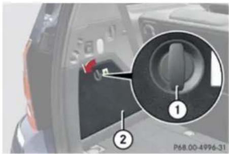
text_image
P68.00-4996-31① Lock
② Cover in driver's side trim panel
▶ Turn lock ① by 90° in direction of the arrow.
▶ Fold down cover ②.
The first aid kit can be removed.
Vehicle tool kit
The vehicle tool kit is located in the space underneath the cargo compartment floor.
The vehicle tool kit includes:
- Alignment bolt
• Collapsible wheel chock - Fuse chart
- Jack
• Reversible ratchet for jack - Towing eye bolt
- Wheel wrench
- Spare wheel bolts ^16
Removing: Open the tailgate (▷ page 90).
Practical hints
Where will I find ...?
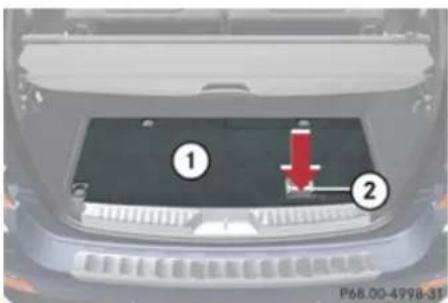
text_image
① ② P68.00-4998-31① Cargo compartment floor, lowered
② Floor handle
▶ Push in floor handle ② as indicated by arrow.
▶ Lift cargo compartment floor ① using floor handle ②.
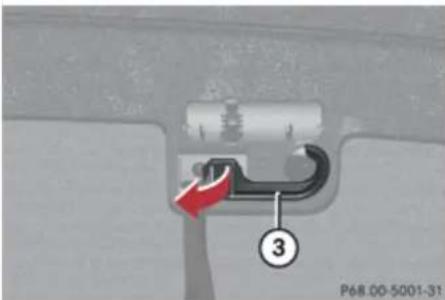
text_image
P68.00-5001-31 ③③ Securing hook
▶ Release securing hook ③ (located below the floor handle) from holder.
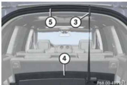
text_image
⑤ ③ ④ P68.00-4999 S1③ Securing hook
④ Cargo compartment floor, raised
⑤ Upper cargo compartment lip
▶ Engage securing hook ③ on upper cargo compartment lip ⑤.
! With the cargo compartment cover blind installed behind the third-row seats, disengage cargo compartment cover blind and flip it forward. Otherwise the strap of the securing hook could damage the cargo compartment cover blind.
! To prevent damage, always disengage the securing hook from upper cargo compartment lip and lower the cargo compartment floor before closing the tailgate.
Practical hints
Where will I find ...?
Vehicles without spare wheel
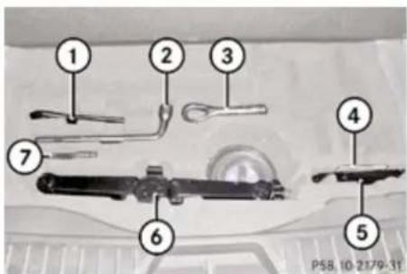
text_image
1 2 3 4 5 6 7 P58.10-2179-31① Reversible ratchet for jack
② Wheel wrench
③ Towing eye bolt
④ Fuse chart
⑤ Collapsible wheel chock
⑥ Jack
⑦ Alignment bolt
Vehicles with spare wheel
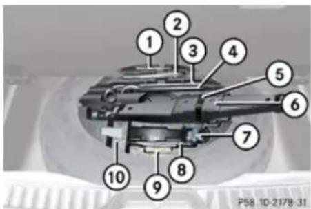
text_image
1 2 3 4 5 6 7 8 9 10 P58.10-2178-31① Alignment bolt
② Towing eye bolt
③ Wheel wrench
④ Reversible ratchet for jack
⑤ Hook and loop fastener
⑥ Jack
⑦ Spare wheel bolts
⑧ Collapsible wheel chock
⑨ Fuse chart
⑩ Storage well casing
▶ To remove jack ⑥, loosen hook and loop fastener ⑤.
Collapsible wheel chock
The collapsible wheel chock serves to secure the vehicle, e.g. while changing a wheel.
▶ Take the collapsible wheel chock from the vehicle tool kit (> page 326).
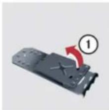
natural_image
Mechanical component with a red arrow and circled number 1, no visible text or symbols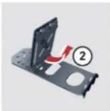
natural_image
Mechanical component with highlighted section and red arrow indicating motion (no text or symbols)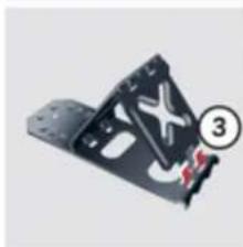
natural_image
Mechanical component with a black triangular frame and red circular annotation (numbered 3), no visible text or symbols.
natural_image
Metal bracket component (no visible text or symbols)① Tilt the plates upward
② Fold the lower plate outward
③ Insert the plate
Practical hints
Where will I find ...?
Setting up: Tilt both plates upward ①.
▶ Fold the lower plate outward ②.
▶ Guide the tabs of the lower plate all the way into the openings of base plate ③.
For information on where to place wheel chocks when changing a wheel, see "Lifting the vehicle" (▷ page 398).
Jack

Warning!
Only use the jack supplied with your vehicle to lift the vehicle briefly for wheel changes. If you use the jack for any other purpose, you or others could be injured, as the jack is designed only for the purpose of changing a wheel.
When using the jack, observe the safety notes in the "Mounting the spare wheel" section and the notes on the jack.
▶ Take the jack from the vehicle tool kit (> page 326).
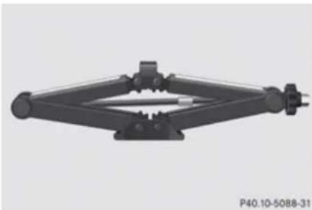
natural_image
Mechanical linkage component with mounting base and central shaft (no text or symbols visible)Storage position
▶ Take the reversible ratchet from the vehicle tool kit.
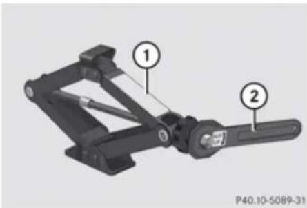
text_image
① ② P40.10-5089-31Operational position
① Jack
② Reversible ratchet
▶ Attach reversible ratchet ② to jack ① in such a way that the word UP can be seen.
Before placing the jack back into the vehicle tool kit:
▶ Fully collapse the jack (storage position).
▶ Remove the reversible ratchet.
Spare wheel

Observe Safety notes, see page 397.
i The GL 320 BlueTEC does not have a spare wheel.
The spare wheel is located in the space underneath the cargo compartment floor.
▶ Removing: Open the tailgate (▷ page 90).
▶ Lift the cargo compartment floor (▷ page 327).
! To prevent damage, always disengage the securing hook from upper cargo compartment lip and lower the cargo compartment floor before closing the tailgate.
▶ Remove the jack from the vehicle tool kit (▷ page 328).
Practical hints
Vehicle status messages in the multifunction display
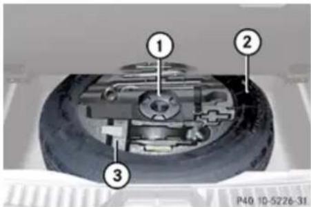
text_image
① ② ③ P40 10-5226-31① Retaining screw
② Spare wheel
③ Storage well casing
Remove retaining screw ① by turning it counterclockwise.
If retaining screw ① does not come loose, turn storage well casing ③ slightly counterclockwise. Retaining screw ① should then come loose easily.
▶ Remove storage well casing ③.
▶ Remove spare wheel ②.
For information on mounting the spare wheel, see "Flat tire" ( page 397).
Storing the spare wheel after use
▶ Place the spare wheel into the spare wheel well (▶ page 330).
▶ Place the storage well casing into the spare wheel (▷ page 330).
▶ Secure the spare wheel by turning the retaining screw (> page 330) clockwise.
▶ Place the jack into the storage well casing (▷ page 328).
▶ Close and pull tight the hook and loop fastener (> page 328) that secures the jack.
Vehicle status messages in the multifunction display
Notes
Warning and malfunction messages appear in the multifunction display located in the instrument cluster.
Certain warning and malfunction messages are accompanied by an audible signal.
Address these messages accordingly and follow the additional instructions given in this Operator's Manual.
Selecting the Vehicle status message memory menu in the control system (▷ page 156) displays both cleared and uncleared messages.
High-priority messages appear in the multifunction display in red color.
Certain messages of high priority cannot be cleared from the multifunction display using the reset button (▷ page 147) or button
, or on the multifunction steering wheel.
Other messages of high priority and messages of less immediate priority can be cleared from the multifunction display using the reset button (> page 147) or button
, or on the
Practical hints
Vehicle status messages in the multifunction display
multifunction steering wheel. They are then stored in the Vehicle status message memory menu (▷ page 156). Remember that clearing a message will only make the message disappear. Clearing a message will not correct the condition that caused the message to appear.

Warning!
All categories of messages contain important information which should be taken note of and, where a malfunction is indicated, addressed as soon as possible at an authorized Mercedes-Benz Center.
Failure to repair the condition noted may cause damage not covered by the Mercedes-Benz Limited Warranty, or result in property damage or personal injury.

Warning!
No messages will be displayed if either the instrument cluster or the multifunction display is inoperative.
As a result, you will not be able to see information about your driving conditions, such as speed or outside temperature,
warning/indicator lamps, malfunction/warning messages or the failure of any systems. Driving characteristics may be impaired.
If you must continue to drive, please do so with added caution. Contact an authorized Mercedes-Benz Center as soon as possible.
On the pages that follow, you will find a compilation of the most important warning and malfunction messages that may appear in the multifunction display.
For your convenience the messages are divided into text messages (▷ page 332) and symbol messages (▷ page 346).
Practical hints
Vehicle status messages in the multifunction display
Text messages
Safety systems
| Display messages Possible cause/consequence Possible solution | |||
| ABS ABS, ESP | Inoperative See Operator's Manual | The brake system is still functioning normally but due to a malfunction, the ABS, the BAS and the ESP® are unavailable. | ► Continue driving with added caution. Wheels may lock during hard braking, reducing steering capability. ► Have the system checked at an authorized Mercedes-Benz Center as soon as possible. Failure to follow these instructions increases the risk of an accident. |
| ABS ABS, ESP | Unavailable See Operator's Manual | The self-diagnosis may not be completed yet. | The display will clear after driving a short distance at a vehicle speed of above 12 mph (20 km/h). |
| ABS ABS, ESP | Unavailable See Operator's Manual | The brake system still functions normally but due to insufficient power supply, the ABS, the BAS and the ESP® are unavailable. | When the voltage is above the required value again, the ABS is operational again and the message should disappear. ► If the message does not disappear: Have the system checked at an authorized Mercedes-Benz Center as soon as possible. |
Practical hints
Vehicle status messages in the multifunction display
| Display messages Possible cause/consequence Possible solution | |||
| ESP Inoperative | See Operator's Manual | In addition, the yellow ESP® warning lamp ⚠️ comes on.The brake system is still functioning normally but due to a malfunction the ESP® is unavailable.The ABS and the BAS may not be operational. | ▸ Continue driving with added caution.▸ Have the system checked at an authorized Mercedes-Benz Center as soon as possible.Failure to follow these instructions increases the risk of an accident. |
| ESP Unavailable | See Operator's Manual | The brake system still functions normally but due to insufficient power supply the ESP® is unavailable. | ▸ Continue driving with added caution.When the voltage is above the required value again, the ESP® is operational again and the message in the multifunction display should disappear.If the message in the multifunction display does not disappear:▸ Have the alternator and the battery checked.▸ Have the system checked at an authorized Mercedes-Benz Center as soon as possible. |
| ESP Unavailable | See Operator's Manual | If the yellow ESP® warning lamp ⚠️ flashes while driving and this message appears, the 4-ETS has switched off to prevent overheating of the drive wheel brakes. | As soon as the brakes have cooled off, the 4-ETS switches on again.The message in the multifunction display disappears and the ESP® warning lamp ⚠️ goes out. |
▶▶
Practical hints
Vehicle status messages in the multifunction display
| Display messages Possible cause/consequence Possible solution | |||
| ESP Unavailable | See Operator's Manual | The self-diagnosis might not be completed yet. | The display will clear after driving a short distance at a vehicle speed of above 12 mph (20 km/h). |
| PRE-SAFE Inoperative See Operator's Manual | The PRE-SAFE® system itself has failed. All other occupant safety systems, such as the air bags, are still available. | ► Contact an authorized Mercedes-Benz Center as soon as possible. | |
| If ESP® and PRE-SAFE® malfunction messages are displayed simultaneously, the PRE-SAFE® system has been deactivated as a result of these malfunctions. All other occupant safety systems, such as the air bags, are still available. | ► Contact an authorized Mercedes-Benz Center as soon as possible. | ||
Practical hints
Vehicle status messages in the multifunction display
Display messages Possible cause/consequence Possible solution
| Front Passenger Airbag Enabled See Operator's Manual | USA only:The front passenger front air bag is activated while driving even though a child, small individual, or object below the system's weight threshold is on the front passenger seat, or the front passenger seat is empty. Objects on the seat or forces acting on the seat may make the system sense supplemental weight. | ▸ Stop the vehicle in a safe location as soon as possible.▸ Engage the parking brake.▸ Switch off the ignition.▸ Open the front passenger door.▸ Remove child and child restraint from front passenger seat and properly secure the child in rear seat employing the child restraint if necessary.▸ Remove any other items from on and around the front passenger seat and make sure the parcel net on the back of the front passenger seat is empty.▸ Make sure no objects which apply forces to the seat are present (e.g. objects such as books, briefcases etc. lodged behind or around the seat, head restraints pushing against roof etc.). The system may recognize such forces as supplemental weight and sense that an occupant on the front passenger seat is of a greater weight than actually present.▸ Keep the seat unoccupied, close the front passenger door and switch on the ignition. |
Practical hints
Vehicle status messages in the multifunction display
Display messages Possible cause/consequence Possible solution
Monitor the PASS AIR BAG OFF indicator lamp in the center console (▷ page 56) and the multifunction display in the instrument cluster (▷ page 32) for the following:
With the seat unoccupied and the ignition switched on,
- the PASS AIR BAG OFF indicator lamp in the center console should illuminate and remain illuminated, indicating that the OCS (▶ page 53) has deactivated the front passenger front air bag.
- the message Front Passenger Airbag Enabled See Operator's Manual or the message Front Passenger Airbag Disabled See Operator's Manual should not appear in the multifunction display at any time the seat is unoccupied. Wait at least 60 seconds for the system to complete the necessary check cycles and to make sure neither message appears in the multifunction display.
If above conditions are met, you can occupy the front passenger seat again. Depending on the front passenger classification sensed by the
Practical hints
Vehicle status messages in the multifunction display
Display messages Possible cause/consequence Possible solution
OCS, the PASS AIR BAG OFF indicator lamp will remain illuminated or go out. If above conditions are not met, the system is not working properly. Have the system checked as soon as possible at an authorized Mercedes-Benz Center.

Warning!
If the 2 PASS AIR BAC OFF indicator lamp remains out even after performing the above corrective steps, do not have any children 12 years old and under and other small individuals use the front passenger seat until the system has been repaired.
Practical hints
Vehicle status messages in the multifunction display
| Display messages Possible cause/consequence Possible solution | ||
| Front Passenger Airbag Disabled See Operator's Manual | USA only:The front passenger front air bag is deactivated while driving even though an adult or someone larger than a small individual is occupying the front passenger seat. Forces acting on the seat may make the system sense a decrease in weight. | |
| Monitor thePASS AIR BAG OFF indicator lamp in the center console (▶ page 56) and the multifunction display in the instrument cluster (▶ page 32) for the following: | ||
Practical hints
Vehicle status messages in the multifunction display
Display messages Possible cause/consequence Possible solution
With the seat unoccupied and the ignition switched on,
- the PASS AIR BAD OFF indicator lamp in the center console should illuminate and remain illuminated, indicating that the OCS (▷ page 53) has deactivated the front passenger front air bag.
- the message Front Passenger Airbag Enabled See Operator's Manual or the message Front Passenger Airbag Disabled See Operator's Manual should not appear in the multifunction display at any time the seat is unoccupied. Wait at least 60 seconds for the system to complete the necessary check cycles and to make sure neither message appears in the multifunction display.
If above conditions are met, you can occupy the front passenger seat again. Depending on the front passenger classification sensed by the OCS, the PASS AIR BAG OFF indicator lamp will remain illuminated or go out.
If above conditions are not met, the system is not working properly. Have the system checked as
▶▶
Practical hints
Vehicle status messages in the multifunction display
| Display messages Possible cause/consequence Possible solution | ||
| soon as possible at an authorized Mercedes-Benz Center. | ||

Warning!
If the 2 PASS AIR BAG DFF indicator lamp remains illuminated with an adult occupant on the front passenger seat even after performing the above corrective steps, do not have any passenger use the front passenger seat until the system has been repaired.
Driving systems
| Display messages Possible cause/consequence Possible solution | |||
| Cruise Control Inoperative | The cruise control is malfunctioning. | ▸ Have cruise control checked at an authorized Mercedes-Benz Center. | |
| Cruise Control - - - MPH (USA only) - - - Km/h (Canada only) | One of the activation conditions for cruise control has not been fulfilled. For example, you have attempted to set a speed below 20 mph (30 km/h). | ▸ Drive faster than 20 mph (30 km/h), if the situation allows, and set the speed.▸ Check the activation conditions for cruise control (▷ page 170). | |
| DISTRONIC - - - Km/h (Canada only) | One of the activation conditions for Distronic has not been fulfilled. For example, you have attempted to set a speed below 20 mph (30 km/h). | ▸ Drive faster than 20 mph (30 km/h) and set the speed.▸ Check the activation conditions for Distronic (▷ page 176). | |
Practical hints
Vehicle status messages in the multifunction display
| Display messages Possible cause/consequence Possible solution | |||
| DISTRONIC Inoperative | The Distronic or the display are malfunctioning. | ▸ Contact an authorized Mercedes-Benz Center as soon as possible. | |
| DISTRONIC Override | You have accelerated. The Distronic has switched off. | ▸ Stop accelerating. | |
| DISTRONIC Available Again | Distronic had been deactivated and is available again. | ▸ Activate Distronic (▸ page 176). | |
| DISTRONIC Currently Unavailable See Operator's Manual | Distronic is deactivated because:• The Distronic cover in the radiator grille is dirty.• The functionality is impaired by heavy precipitation or fog• The system is overheated. | ▸ If necessary, clean the Distronic cover in the area of the radiator grille (▸ page 321).▸ If necessary, wait until the system has cooled down.▸ Restart the vehicle.Distronic becomes operational again without the engine being restarted when:• dirt on the radiator grille has fallen off while driving (e.g. slush or snow)• the system recognizes full sensor availability (due to lessening rain or the road surface drying)• the message in the multifunction display disappearsYou can then operate Distronic as usual again. | |
Practical hints
Vehicle status messages in the multifunction display
| Display messages Possible cause/consequence Possible solution | |||
| DISTRONIC CurrentlyUnavailableSee Operator's Manual | Distronic is deactivated because the functionality is impaired by external interferences, e.g. high-frequency sources such as toll stations, speed measuring systems etc. | ▸ Leave the area of the external interference.▸ Activate Distronic again (▸ page 176) when the message DISTRONIC Available Again appears. | |
| Distronic is deactivated because the Distronic sensor has not sensed any other vehicles or objects, e.g. road sign or such, for a long time. | ▸ Activate Distronic again (▸ page 176) when the message DISTRONIC Available Again appears. | ||

Warning!
Distronic cannot take weather conditions into account. Switch off Distronic or do not turn it on if the sensor is dirty or visibility is diminished as a result of snow, rain or fog. The distance control may be impaired even before the system is able to detect a dirty sensor. The message DISTRONIC Currently Unavailable See Operator's Manual will be displayed in the multifunction display and Distronic will be turned off.
Practical hints
Vehicle status messages in the multifunction display
Vehicle
| Display messages Possible cause/consequence Possible solution | |||
| Depress brake to | shift out of P. | You have attempted to shift the automatic transmission into drive position D, reverse gear R or neutral position N without depressing the brake pedal. | ▸ Depress the brake pedal. |
| Door Open Vehicle | Not In Park | You have opened the driver's door and the automatic transmission is still in drive position D, reverse gear R or neutral position N. | ▸ Before you leave the vehicle, make sure the automatic transmission is in park position P and the parking brake is engaged. |
| Drive to workshop | without shifting gears. | The automatic transmission cannot be shifted out of the current transmission position because of a malfunction. | If the automatic transmission is in drive position D:▸ Without shifting the automatic transmission out of drive position D, drive to an authorized Mercedes-Benz Center.If the automatic transmission is set to position neutral position N, reverse gear R or park position P:▸ Do not drive.▸ Contact an authorized Mercedes-Benz Center or call Roadside Assistance. |
▶▶
Practical hints
Vehicle status messages in the multifunction display
| Display messages Possible cause/consequence Possible solution | |||
| Only shift to P when vehicle is at a standstill. | You have attempted to shift the automatic transmission into park position P although the vehicle was still in motion. | ► Stop the vehicle. | |
| P Shift to P or N to start engine. | You have attempted to start the engine with the KEYLESS-GO start/stop button while the automatic transmission was in reverse gear R or drive position D. | ► Shift the automatic transmission into park position P or neutral position N. Make sure the brake pedal is depressed. | |
Tires
| Display messages Possible cause/consequence Possible solution | |||
| Check tires, then restart Run Flat Indicator. | There has been a warning message about a loss in the tire inflation pressure and the Run Flat Indicator was not restarted yet. | Make sure the correct tire inflation pressure is set for each tire.Then restart the Run Flat Indicator (▷ page 282). | |
| Run Flat Indicator Inoperative | The Run Flat Indicator is malfunctioning. | Have the Run Flat Indicator checked at an authorized Mercedes-Benz Center. | |
Practical hints
Vehicle status messages in the multifunction display
| Display messages Possible cause/consequence Possible solution | |||
| Tire Pressure Check Tires | The Run Flat Indicator indicates that the pressure is too low in one or more tires. | ► Carefully bring the vehicle to a halt, avoiding abrupt steering and braking maneuvers. Observe the traffic situation around you. ► Check and adjust tire inflation pressure as required (▷ page 281). ► If necessary, change the wheel (▷ page 397). ► Restart the Run Flat Indicator after adjusting the tire inflation pressure values (▷ page 282). | |
| Tire Pressure Monitor | Inoperative | The TPMS is malfunctioning. | ► Have the TPMS checked at an authorized Mercedes-Benz Center. |
| Tire Pressure Monitor | Inoperative No Wheel Sensors | There are wheels without appropriate wheel sensors mounted (e.g. winter tires). | ► Have the TPMS checked at an authorized Mercedes-Benz Center. ► Have the appropriate wheel sensors installed at an authorized Mercedes-Benz Center. |
| Tire Pressure Monitor | Currently Unavailable | The TPMS is unable to monitor the tire inflation pressure due to a nearby radio interference source or insufficient power supply. | As soon as the causes of the malfunction have been removed, the TPMS becomes active again automatically after a few minutes driving. |
Practical hints
Vehicle status messages in the multifunction display
Warning!
Do not drive with a flat tire. A flat tire affects the ability to steer or brake the vehicle. You may lose control of the vehicle. Continued driving with a flat tire will cause excessive heat build-up and possibly a fire.
Warning!
Follow recommended tire inflation pressures.
Do not underinflate tires. Underinflated tires wear excessively and/or unevenly, adversely affect handling and fuel economy, and are more likely to fail from being overheated.
Do not overinflate tires. Overinflated tires can adversely affect handling and ride comfort, wear unevenly, increase stopping distance, and result in sudden deflation (blowout) because they are more likely to become punctured or damaged by road debris, potholes etc.
Symbol messages
Brake
Display messages Possible cause/consequence Possible solution

Brake Wear
The brake pads have reached their wear limit.
▶ Have the brake pads replaced as soon as possible.
! Brake pad thickness must be visually inspected by a qualified technician at the intervals specified in the Maintenance Booklet.
Practical hints
Vehicle status messages in the multifunction display
| Display messages Possible cause/consequence Possible solution | |||
   (Canada only) (Canada only) | EBV, ABS, ESP Inoperative See Operator's Manual | The brake system is still functioning normally but due to a malfunction, the ABS, the BAS, the EBP and the ESP® are unavailable. | ► Continue driving with added caution. Wheels may lock during hard braking, reducing steering capability.► Adjust driving to be consistent with reduced braking responsiveness.► Have the system checked at an authorized Mercedes-Benz Center as soon as possible. |
   (Canada only) (Canada only) | Release Parking Brake | You are driving with the parking brake engaged. | ► Release the parking brake. |
   (Canada only) (Canada only) | Check Brake Fluid Level | There is insufficient brake fluid in the reservoir. | Risk of accident!► Stop the vehicle in a safe location or as soon as it is safe to do so.► Do not drive any further.► Contact an authorized Mercedes-Benz Center or call Roadside Assistance.Do not add brake fluid! This will not solve the problem. |
Practical hints
Vehicle status messages in the multifunction display
Warning!
Driving with the message Check Brake Fluid Level displayed can result in an accident. Have your brake system checked immediately. Do not add brake fluid before checking the brake system. Overfilling the brake fluid reservoir can result in spilling brake fluid on hot engine parts and the brake fluid catching fire. You can be seriously burned.
! If you find that the brake fluid in the brake fluid reservoir has fallen to the minimum mark or below, have the brake system checked for brake pad thickness and leaks.
Safety systems
| Display messages Possible cause/consequence Possible solution | |||
 | Tele Aid Inoperative | One or more main functions of the Tele Aid system are malfunctioning. | Have the Tele Aid system checked at an authorized Mercedes-Benz Center. |
 | Restraint Sys. Malfunction Service Required | The system is malfunctioning. | Drive with added caution to the nearest authorized Mercedes-Benz Center and have the system checked immediately. |
Warning!
In the event a malfunction of the SRS is indicated as outlined above, the SRS may not be operational.
For your safety, we strongly recommend that you contact an authorized Mercedes-Benz Center immediately to have the system checked. Otherwise the SRS may not be activated when needed in an accident, which could result in serious or fatal injury, or it might deploy unexpectedly and unnecessarily which could also result in injury.
Practical hints
Vehicle status messages in the multifunction display
Driving systems
| Display messages Possible cause/consequence Possible solution | |||
 | Level SelectionNot Permitted | The selected vehicle level cannot adjusted, becauseyou are driving too fast for the desired vehicle levelyou are towing a traileryou are using accessories that are connected to the trailer power socket, e.g. a bicycle rack | ▸ Reduce vehicle speed and set the desired vehicle level again (▷ page 186).▸ Observe the notes on trailer towing (▷ page 310). |
 | Malfunction | The air suspension is malfunctioning. | ▸ Do not drive faster than 50 mph (80 km/h).▸ Have the system checked at an authorized Mercedes-Benz Center. |
Practical hints
Vehicle status messages in the multifunction display
| Display messages Possible cause/consequence Possible solution | |||
 | Compressor Cooling Down | You have selected a higher vehicle level. Due to frequent level changes within a short period, the compressor must cool down first.⚠ When the message Compressor Cooling Down appears in the multifunction display, driving is still possible. Keep in mind that the ride height of the vehicle is not yet reached, so you can damage the underbody of the vehicle. | ▶ Let the compressor cool down until the message disappears.The selected level will be set once the compressor has cooled down. |
 | Rising Max. 12 MPH | The vehicle is adjusting to off-road level 3. | ▶ Do not drive faster than 12 mph (20 km/h). |
 | Max. 12 MPH | You are driving while using off-road level 3. The message reminds you of the maximum speed at which you may drive with off-road level 3. | ▶ Do not drive faster than 12 mph (20 km/h). |
 | Being lowered Max. 12 MPH | The vehicle is being lowered from off-road level 3 to off-road level 2. | ▶ Do not drive faster than 12 mph (20 km/h) until the off-road level 2 is reached. |
Practical hints
Vehicle status messages in the multifunction display
| Display messages Possible cause/consequence Possible solution | |||
 | Reduce speed to under 12 MPH | You are driving too fast for the set vehicle level.⚠ Warning!Adapt your driving style to the modified driving conditions. Avoid extreme, quick steering maneuvers. Please keep in mind that the driving characteristics of the vehicle have been modified. You should therefore drive in off-road level 3 with particular caution as it could otherwise lead to an accident and/or serious injury to you or others. | ▸ Do not drive faster than 12 mph (20 km/h) until the off-road level 2 is reached. |
 | Locking System Inoperative Service Required | The differential locks are malfunctioning. | ▸ Do not drive faster than 50 mph (80 km/h).▸ Have the vehicle checked at an authorized Mercedes-Benz Center. |
 | Diff. Lock System Overheated - Wait briefly. | The differential locks are too hot and have been deactivated as a result. | ▸ Continue driving with added caution. The lock function is unavailable.▸ Wait for the lock system to cool down.The differential locks will be reactivated as soon as they have cooled down. |
▶▶
Practical hints
Vehicle status messages in the multifunction display
| Display messages Possible cause/consequence Possible solution | |||
 | Stop vehicle. engage parking brake. | A shifting procedure could not be completed. LOW RANGE is in neutral position. There is no connection between the engine and the drive wheels. | ▸ Do not attempt to continue driving. You could otherwise damage the vehicle's drivetrain.▸ Stop the vehicle in a safe location or as soon as it is safe to do so.▸ Engage the parking brake.▸ Perform the shifting procedure again (▷ page 142). |
 | Service Required If parked engage pk. brake. | The LOW RANGE system is malfunctioning. | ▸ Do not drive faster than 50 mph (80 km/h).▸ Engage the parking brake if parked.▸ Contact an authorized Mercedes-Benz Center as soon as possible. |
 | Max. Speed 25 MPH | Speed too high for shifting procedure. | ▸ Continue driving more slowly.The shifting procedure will be performed. |
 | Max. Speed 40 MPH | Speed too high for shifting procedure. | ▸ Continue driving more slowly.The shifting procedure will be performed. |
 | Shift briefly into N. | You have reduced engine speed, but the automatic transmission is not in neutral position N. | ▸ Briefly shift automatic transmission to neutral position N. |
Practical hints
Vehicle status messages in the multifunction display
| Display messages Possible cause/consequence Possible solution | ||||
 | Shifting Process Canceled Reactivate | The shifting procedure was not carried out. | ▸ Repeat the shifting procedure if desired. | |
 | Inoperative | Downhill Speed Regulation is malfunctioning. | ▸ Have the Downhill Speed Regulation checked at an authorized Mercedes-Benz Center. | |
Vehicle
| Display messages Possible cause/consequence Possible solution | |||
 | You are driving with the hood or the tailgate open. | ▸ Close the hood or the tailgate. | |
| You are trying to lock the vehicle with the KEYLESS-GO function with a door or the tailgate open. | ▸ Close all doors and/or the tailgate. | ||
 | You are driving with at least one door open. | ▸ Close all doors. | |
 | Key Detected In Vehicle | A SmartKey with KEYLESS-GO left in the vehicle was recognized while trying to lock the vehicle from the outside. | ▸ Take the SmartKey out of the vehicle. |
▶▶
Practical hints
Vehicle status messages in the multifunction display
| Display messages Possible cause/consequence Possible solution | |||
 | Don't Forget Your Key | This display appears for a maximum of 60 seconds if the driver's door is opened with the engine turned off and no SmartKey in the starter switch. This message is only a reminder. | ▸ Take the SmartKey with you when leaving the vehicle. |
 | Remove Key | You have forgotten to remove the SmartKey. | ▸ Remove the SmartKey from the starter switch. |
 | You need a new key. | The SmartKey is malfunctioning. | ▸ Contact an authorized Mercedes-Benz Center. |
 | Key Does Not Belong to Vehicle | The SmartKey in the starter switch does not belong to the vehicle. | ▸ Find the SmartKey that belongs to the vehicle to operate the vehicle. |
 | Change Key Batteries | The batteries in the SmartKey with KEYLESS-GO are discharged. | ▸ Replace the batteries (▷ page 386). |
 | Key Not Detected | The SmartKey with KEYLESS-GO is not detected while the engine is running because the SmartKey is not in the vehicle. | ▸ Stop the vehicle as soon as it is safe to do so.▸ Engage the parking brake.▸ Search for the SmartKey.The vehicle cannot be locked centrally nor can the engine be started again after the engine is stopped. |
Practical hints
Vehicle status messages in the multifunction display
| Display messages Possible cause/consequence Possible solution | |||
 | Key Not Detected | The SmartKey with KEYLESS-GO is not detected while the engine is running because there is strong radio-frequency interference. | ▸ Stop the vehicle as soon as it is safe to do so.▸ Engage the parking brake.▸ Operate the vehicle with the SmartKey in the starter switch. |
 | Key Not Detected | The SmartKey with KEYLESS-GO is momentarily not detected. | ▸ Change the position of the SmartKey in the vehicle.▸ Operate the vehicle with the SmartKey in the starter switch if necessary. |
 | Pull starting button out then insert key. | The SmartKey with KEYLESS-GO is permanently not detected. | ▸ Operate the vehicle with the SmartKey in the starter switch.▸ Contact an authorized Mercedes-Benz Center. |
 | Bluetooth Ready | The telephone has not yet been connected to the COMAND system via Bluetooth®. | ▸ Connect the telephone to the COMAND system via Bluetooth®. |
 | Top Up Washer Fluid | The fluid level has dropped to approximately 1/3 of total reservoir capacity. | ▸ Add washer fluid (▸ page 271). |
Practical hints
Vehicle status messages in the multifunction display
Engine
Display messages Possible cause/consequence Possible solution
 | Top Up Coolant See Operator's Manual | The coolant level is too low. | ▶ Add coolant (▷ page 271).▶ If you have to add coolant frequently, have the cooling system checked at an authorized Mercedes-Benz Center. |

Warning!
Do not spill antifreeze on hot engine parts. Antifreeze contains ethylene glycol which may burn if it comes into contact with hot engine parts. You could be seriously burned.
! Do not ignore the low engine coolant level warning. Extended driving with the message and symbol displayed may cause serious engine damage not covered by the Mercedes-Benz Limited Warranty.
Do not drive without sufficient amount of coolant in the cooling system. The engine will overheat causing major engine damage.
Practical hints
Vehicle status messages in the multifunction display
Display messages Possible cause/consequence Possible solution
| CoolantStop car, switch engine off. | The coolant is too hot. | ▸ Stop the vehicle immediately as soon as it is safe to do so.▸ Turn off the engine immediately.▸ Engage the parking brake.▸ Only start the engine again after the message disappears. You could otherwise damage the engine.▸ Observe the coolant temperature in the multifunction display.▸ If the temperature rises again: Contact an authorized Mercedes-Benz Center immediately.During severe operation conditions and stop-and-go city traffic, the coolant temperature may rise close to 248°F (120°C). |

Warning!
Driving when your engine is overheated can cause some fluids which may have leaked into the engine compartment to catch fire. You could be seriously burned.
Steam from an overheated engine can cause serious burns which can occur just by opening the engine hood. Stay away from the engine if you see or hear steam coming from it.
Stop the vehicle in a safe location away from other traffic. Turn off the engine, get out of the vehicle and do not stand near the vehicle until the engine has cooled down.
▶▶
Practical hints
Vehicle status messages in the multifunction display
! The engine should not be operated with the coolant temperature above 248°F (120°C). Doing so may cause serious damage which is not covered by the Mercedes-Benz Limited Warranty.
Practical hints
Vehicle status messages in the multifunction display
Display messages Possible cause/consequence Possible solution
| CoolantStop car, switch engine off. | The poly-V-belt could be broken. | ▸ Stop the vehicle immediately as soon as it is safe to do so.▸ Turn off the engine immediately.▸ Check the poly-V-belt.▸If it is broken:Do not continue to drive. Otherwise the engine will overheat due to an inoperative water pump which may result in damage to the engine. Contact an authorized Mercedes-Benz Center.▸If it is intact:Do not continue to drive the vehicle with this message displayed. Doing so could result in serious engine damage that is not covered by the Mercedes-Benz Limited Warranty.▸ Observe the coolant temperature in the multifunction display.▸ Drive to the nearest authorized Mercedes-Benz Center immediately. |
▶▶
Practical hints
Vehicle status messages in the multifunction display
| Display messages Possible cause/consequence Possible solution | ||
 | The cooling fan for the coolant is malfunctioning. | |
 | The battery is no longer charging.Possible causes:alternator malfunctioningbroken poly-V-belta malfunction in the electronic system | |
Practical hints
Vehicle status messages in the multifunction display
| Display messages Possible cause/consequence Possible solution | |||
 | Battery/Alternator Stop Vehicle | The battery is defective. | ▸ Stop the vehicle in a safe location or as soon as it is safe to do so.▸ Engage the parking brake.▸ Do not continue to drive.▸ Contact an authorized Mercedes-Benz Center. |
 | Check engine oil level at next refueling. | The engine oil level is too low. | ▸ Check the engine oil level (▸ page 269) and add engine oil as required (▸ page 270).▸ If you must add engine oil frequently, have the engine checked for possible leaks. |
If the message Check engine oil level at next refueling, appears while the engine is running and at operating temperature, the engine oil level has dropped to approximately the minimum level.
The message will be stored in the vehicle status message memory after you have cleared it from the multifunction display.
Visually check for oil leaks. If there are no obvious oil leaks, drive to the nearest service station to refill your engine oil to the required level.
For information on approved engine oils contact an authorized Mercedes-Benz Center or visit www.mbusa.com (USA only).
! Engine oil level warnings should not be ignored. Extended driving with the symbol displayed could result in serious engine damage that is not covered by the Mercedes-Benz Limited Warranty.
Practical hints
Vehicle status messages in the multifunction display
| Display messages Possible cause/consequence Possible solution | |||
 | The fuel level is low. | ▸ Refuel at the next gas station. | |
 | Reserve Fuel | The fuel level has dropped below the reserve mark. | ▸ Refuel at the next gas station. |
 | Ultra Low-sulfur Diesel Fuel Only | Vehicles with diesel engine only: The fuel level has dropped below the reserve mark. | ▸ Refuel at the next gas station. ▸ Only use commercially available vehicular ULTRA-LOW SULFUR DIESEL FUEL (15 ppm SULFUR MAXIMUM). |
 | Gas Cap Open | A loss of pressure has been detected in the fuel system. The fuel cap may not be closed properly or the fuel system may be leaky. | ▸ Check the fuel cap (▷ page 265). ▸ If it is not closed properly: Close the fuel cap. ▸ If it is closed properly: Have the fuel system checked at an authorized Mercedes-Benz Center. |
 | Replace air filter | The air filter is clogged. | ▸ Have the air filter checked at an authorized Mercedes-Benz Center. |
 | Clean Fuel Filter | There is water in the fuel filter. | ▸ Have the water drained at an authorized Mercedes-Benz Center as soon as possible. |
 | Check Additive See Operator's Manual | The AdBlue® supply is almost depleted. | ▸ Have the AdBlue® tank refilled as soon as possible (▷ page 405). Contact an authorized Mercedes-Benz Center. |
Practical hints
Vehicle status messages in the multifunction display
| Display messages Possible cause/consequence Possible solution | |||
 | RemainingStarts: 20 | The AdBlue® supply has dropped to the minimum level. | Have the AdBlue® tank refilled immediately (▷ page 405).Contact an authorized Mercedes-Benz Center. |
| When the message RemainingStarts: 20 appears in the multifunction display, you can start the engine 20 more times. If you do not add AdBlue®, the engine cannot be started beyond that point. Therefore, fill the AdBlue® tank with approximately 1 gal (3.79 l) AdBlue® (corresponds to approximately 2 refill containers AdBlue®) or have the AdBlue® tank filled at an authorized Mercedes-Benz Center. After AdBlue® was refilled, the engine can be started again. | |||
When the message Remaining
Lamps
| Display messages Possible cause/consequence Possible solution | |||
 | Active Headlamps Inoperative | The active Bi-Xenon headlamp system is malfunctioning. | ▸ Contact an authorized Mercedes-Benz Center as soon as possible. |
 | Reverse Lamp Left or Reverse Lamp Right | The left or right backup lamp is malfunctioning. | ▸ Replace the bulb as soon as possible (▸ page 388). |
 | Brake Lamp Left or Brake Lamp Right | The left or right brake lamp is malfunctioning. A substitute bulb is being used. | ▸ Replace the bulb as soon as possible (▸ page 388). |
▶▶
Practical hints
Vehicle status messages in the multifunction display
| Display messages Possible cause/consequence Possible solution | |||
| [W75S] | 3rd Brake Lamp | The high-mounted brake lamp is malfunctioning. This message will only appear if all LEDs have stopped working. | ▸ Contact an authorized Mercedes-Benz Center as soon as possible. |
 | Front Foglamp Left or Front Foglamp Right | The left or right front fog lamp is malfunctioning. | ▸ Replace the bulb as soon as possible (▷ page 388). |
 | Marker Lamp Front Left or Marker Lamp Front Right | The front left side or right side marker lamp is malfunctioning. | ▸ Replace the bulb as soon as possible (▷ page 388). |
 | Parking Lamp Front Left or Parking Lamp Front Right | The left or right front parking lamp is malfunctioning. A substitute bulb is being used. | ▸ Replace the bulb as soon as possible (▷ page 388). |
 | High Beam Left or High Beam Right | The left or right high-beam lamp is malfunctioning. | ▸ Halogen headlamp: Replace the bulb as soon as possible (▷ page 390).▸ Bi-Xenon headlamp: Contact an authorized Mercedes-Benz Center as soon as possible. |
Practical hints
Vehicle status messages in the multifunction display
| Display messages Possible cause/consequence Possible solution | |||
 | License Plate Lamp Left or License Plate Lamp Right | The left or right license plate lamp is malfunctioning. | ► Replace the bulb as soon as possible (▷ page 388). |
 | AUTO Light Inoperative | The light sensor is malfunctioning. The headlamps come on automatically. | ► Contact an authorized Mercedes-Benz Center as soon as possible.To switch off the headlamps (U.S. vehicles only): ► In the control system, set daytime running lamp mode to manual (▷ page 161). ► Switch off the headlamps using the exterior lamp switch (▷ page 115). |
 | Low Beam Left or Low Beam Right | The left or right low-beam lamp is malfunctioning. | ► Halogen headlamp: Replace the bulb as soon as possible (▷ page 388). ► Bi-Xenon headlamp: Contact an authorized Mercedes-Benz Center as soon as possible. |
 | Foglamp Rear Left | The rear fog lamp is malfunctioning. | ► Replace the bulb as soon as possible (▷ page 388). |
▶▶
Practical hints
Vehicle status messages in the multifunction display
| Display messages Possible cause/consequence Possible solution | |||
 | Switch Off Lights | You have removed the SmartKey from the starter switch, opened the driver's door and left the headlamps on or removed the SmartKey with KEYLESS-GO from the vehicle and left the headlamps on. | ▶ Turn the exterior lamp switch to 0 or AUTO (▷ page 115).or▶ With the rear fog lamp switched on: Push in the exterior lamp switch to its stop. |
 | Tail Lamp Left or Tail Lamp Right | The left or right tail lamp is malfunctioning. A substitute bulb is being used. | ▶ Replace the bulb as soon as possible (▷ page 388). |
 | Cornering Lamp Left or Cornering Lamp Right | The left or right corner-illuminating front fog lamp is malfunctioning. | ▶ Replace the bulb as soon as possible (▷ page 388). |
 | Trailer Brake Lamp | The left or right trailer brake lamp is malfunctioning. | ▶ Replace the bulb as soon as possible. |
 | Trailer Tail Lamp Left or Trailer Tail Lamp Right | The left or right trailer tail lamp is malfunctioning. | ▶ Replace the bulb as soon as possible. |
Practical hints
Vehicle status messages in the multifunction display
| Display messages Possible cause/consequence Possible solution | |||
 | Trailer Turn Signal Left or Trailer Turn Signal Right | The left or right trailer turn signal lamp is malfunctioning. | ► Replace the bulb as soon as possible. |
 | Turn Signal Rear Left or Turn Signal Rear Right | The left or right rear turn signal lamp is malfunctioning. A substitute bulb is being used. | ► Replace the bulb as soon as possible (▷ page 388). |
 | Turn Signal Front Left or Turn Signal Front Right | The left or right front turn signal lamp is malfunctioning. A substitute bulb is being used. | ► Replace the bulb as soon as possible (▷ page 390). |
 | Turn Signal Left Mirror or Turn Signal Right Mirror | The turn signal in the left or right exterior rear view mirror is malfunctioning. This message will only appear if all LEDs have stopped working. | ► Contact an authorized Mercedes-Benz Center as soon as possible. |
Practical hints
Vehicle status messages in the multifunction display
Tires
| Display messages Possible cause/consequence Possible solution | |||
 | Tire pressure(s) Please Correct | The tire pressure is too low in one or more tires. or The tire pressure of the individual tires differ from each other significantly. | ▶ Check and correct tire inflation pressure as required (▷ page 281). |
 | Tire Pressure Caution: Tire Defect | One or more tires are deflating. | ▶ Carefully bring the vehicle to a halt, avoiding abrupt steering and braking maneuvers. ▶ If necessary, change the wheel (▷ page 397). |
 | Tire Pressure Check Tires | The tire pressure in one or more tires is already below the minimum value. | ▶ Carefully bring the vehicle to a halt, avoiding abrupt steering and braking maneuvers. ▶ Check and adjust tire pressure as required. ▶ If necessary, change the wheel (▷ page 397). |
Warning!
Do not drive with a flat tire. A flat tire affects the ability to steer or brake the vehicle. You may lose control of the vehicle. Continued driving with a flat tire will cause excessive heat build-up and possibly a fire.
Warning!
Follow recommended tire inflation pressures.
Do not underinflate tires. Underinflated tires wear excessively and/or unevenly, adversely affect handling and fuel economy, and are more likely to fail from being overheated.
Practical hints
Vehicle status messages in the multifunction display
Do not overinflate tires. Overinflated tires can adversely affect handling and ride comfort, wear unevenly, increase stopping distance, and result in sudden deflation (blowout) because they are more likely to become punctured or damaged by road debris, potholes etc.
Practical hints
What to do if ...
What to do if ...
Lamps in instrument cluster
Notes
If any of the following lamps in the instrument cluster fails to come on during the bulb self-
check when switching on the ignition, have the respective bulb checked and replaced if necessary.
When you switch on the ignition, all lamps (except high-beam headlamp indicator lamp, and turn signal indicator lamps unless activated) in the instrument cluster come on. If a lamp in the instrument cluster fails to come on when the ignition is switched on, have it checked and replaced if necessary.
Practical hints
What to do if ...
Brake
| Problem Possible cause/consequence Suggested solutions | ||
| The yellow ABS indicator lamp comes on while the engine is running. | The ABS has detected a malfunction and switched off.The BAS, ESP®, EBP and Electronic Traction System (4-ETS) are also switched off (see messages in multifunction display).The brake system is still functioning normally but without the systems specified above available.If the ABS control unit is malfunctioning, other systems such as the navigation system or the automatic transmission may also be malfunctioning. | |
| The yellow ABS indicator lamp comes on while the engine is running. | The ABS has switched off due to insufficient power supply.The battery might not be charged sufficiently. | |
▶▶
Practical hints
What to do if ...
| Problem Possible cause/consequence Suggested solutions | ||
| The yellow ABS indicator lamp comes on while the engine is running. | The self-diagnosis has not yet been completed yet. | |
| BRAKE (USA only)(1) (Canada only)(2)The red brake warning lamp comes on while driving. In addition, the yellow ABS malfunction indicator lamp, and the yellow ESP® warning lamp come on and an acoustic warning sounds. | The Electronic Brake Proportioning (EBP) switched off due to a malfunction.The ABS, the BAS, and the ESP® are also switched off. | Have the system checked at an authorized Mercedes-Benz Center as soon as possible.Failure to follow these instructions increases the risk of an accident. |
| BRAKE (USA only)(1) (Canada only)The red brake warning lamp comes on while driving and you hear a warning sound. | You are driving with the parking brake engaged. | Release the parking brake. |
Practical hints
What to do if ...
Problem Possible cause/consequence Suggested solutions
| BRAKE (USA only)(1) (Canada only)The red brake warning lamp comes on while the engine is running and you hear a warning sound. | There is insufficient brake fluid in the reservoir. | ▸ Risk of accident! Do not drive any further. Stop the vehicle in a safe location as soon as it is safe to do so.▸ Engage the parking brake.▸ Read and observe messages that may appear in the multifunction display (▷ page 330).▸ Contact an authorized Mercedes-Benz Center. Do not add brake fluid! This will not solve the problem. |

Warning!
Driving with the brake warning lamp illuminated can result in an accident. Have your brake system checked immediately if the brake warning lamp stays on. Do not add brake fluid before checking the brake system.
Overfilling the brake fluid reservoir can result in spilling brake fluid on hot engine parts and the brake fluid catching fire. You can be seriously burned.
! If you find that the brake fluid in the brake fluid reservoir has fallen to the minimum mark or below, have the brake system checked for brake pad thickness and leaks.
Practical hints
What to do if ...
Safety systems
| Problem Possible cause/consequence Suggested solutions | ||
| The red seat belt telltale comes on for a maximum of 6 seconds after starting the engine. | The seat belt telltale reminds you and your passengers to fasten your seat belts before driving off. | |
| You hear a warning chime for a maximum of 6 seconds after starting the engine. | You have forgotten to fasten your seat belt. | |
| The red seat belt telltale comes on while the vehicle is standing still and the engine is running or during driving. | You and/or your front passenger have forgotten to fasten your seat belts. | |
| There are items placed on the front passenger seat and therefore the system senses the front passenger seat as being occupied. | ||
Practical hints
What to do if ...
Problem Possible cause/consequence Suggested solutions
| During driving the red seat belt telltale flashes and you additionally hear an intermittent warning chime with increasing intensity. | The vehicle’s speed once exceeded 15 mph (25 km/h) and you and/or your front passenger have forgotten to fasten your seat belts. | Fasten your seat belts.The seat belt telltale goes out and the warning chime stops sounding. |
| There are items placed on the front passenger seat and therefore the system senses the front passenger seat as being occupied. | Remove the items from the front passenger seat and put them in a safe place.The seat belt telltale goes out and the warning chime stops sounding. |
After 60 seconds with an unfastened seat belt the warning chime stops sounding and the seat belt telltale illuminates continuously. The seat belt telltale will only go out if both, the driver and front passenger's seat belt are fastened, or the vehicle is standing still and a front door is opened.
| Problem Possible cause/consequence Suggested solutions | ||
| SRS | The red SRS indicator lamp comes on while driving. | There is a malfunction in the restraint systems. The air bags or Emergency Tensioning Devices (ETDs) could deploy unexpectedly or fail to activate in an accident. |
Practical hints
What to do if ...

Warning!
In the event a malfunction of the SRS is indicated as outlined above, the SRS may not be operational.
For your safety, we strongly recommend that you contact an authorized Mercedes-Benz Center immediately to have the system checked. Otherwise the SRS may not be activated when needed in an accident, which could result in serious or fatal injury, or it might deploy unexpectedly and unnecessarily which could also result in injury.
| Problem Possible cause/consequence Suggested solutions | ||
| The yellow ESP® warning lamp comes on while the engine is running. | The ESP® has been switched off. Risk of accident!When the ESP® is switched off it will not stabilize the vehicle if the system recognizes that the vehicle starts to skid or that a wheel is spinning. | |
| The yellow ESP® warning lamp comes on while the engine is running. | The ESP® is not operational due to a malfunction. Risk of accident! | |
Practical hints
What to do if ...
Problem Possible cause/consequence Suggested solutions
| The yellow ESP® warning lamp flashes while driving. | The ESP® or Electronic Traction System (4-ETS) has come into operation because of detected traction loss in at least one tire.The cruise control and the Distronic system are deactivated. | When driving off, apply as little throttle as possible.While driving, ease up on the accelerator pedal.Adapt your speed and driving to the prevailing road and weather conditions.Do not deactivate the ESP®.Exceptions: (▷ page 79).Failure to follow these instructions increases the risk of an accident. |
Driving systems
| Problem Possible cause/consequence Suggested solutions | ||
| The red distance warning lamp comes on while driving. | You are too close to the vehicle in front of you to maintain selected speed. ▶ Apply the brakes immediately to increase the following distance. | |
| The red distance warning lamp comes on while driving and you hear a warning sound. | You are gaining too rapidly on the vehicle ahead of you or the distance warning system has recognized a stationary obstacle on your probable line of travel. ▶ Apply the brakes immediately. ▶ Carefully observe the traffic situation. You may need to brake or maneuver to avoid hitting an obstacle. | |
Practical hints
What to do if ...
Vehicle
Problem Possible cause/consequence Suggested solutions
| The yellow fuel tank reserve warning lamp in the fuel gauge comes on while driving. |
| The fuel level has gone below the reserve mark. |
| Refuel at the next gas station. |
Engine
| Problem Possible cause/consequence Suggested solutions | ||
| CHECK ENGINE (USA only)(Canada only)The yellow engine malfunction indicator lamp comes on when the engine is running. | There may be a malfunction in:· The fuel management system· The ignition system· The emission control system· Systems which affect emissionsSuch malfunctions may result in excessive emissions values and may switch the engine to limp-home (emergency operation) mode. | ▸ Have the vehicle checked as soon as possible at an authorized Mercedes-Benz Center. i Some states may by law require you to visit a workshop as soon as the engine malfunction indicator lamp comes on. Check local requirements. |
| CHECK ENGINE (USA only)(Canada only)The yellow engine malfunction indicator lamp comes on when the engine is running. | A loss of pressure has been detected in the fuel system. The fuel cap may not be closed properly or the fuel system may be leaky. | ▸ Check the fuel cap (▷ page 265).▸ If it is not closed properly: Close the fuel cap.▸ If it is closed properly: Have the fuel system checked by an authorized Mercedes-Benz Center. |
| Diesel engine: Your fuel tank was driven empty. | ▸ After refueling, start, turn off and restart the engine three or four times in succession.The limp-home mode is canceled. You do not need to have your vehicle checked. | |
Practical hints
What to do if ...
Tires
| Problem Possible cause/consequence Suggested solutions | ||
| USA only:Combination low tire pressure telltale/TPMS malfunction telltale for the TPMS illuminates continuously. | The TPMS detects a loss of pressure in at least one tire. | |
Warning!
Each tire, including the spare (if provided), should be checked every other week when cold and inflated to the inflation pressure recommended by the vehicle manufacturer on the Tire and Loading Information placard on the driver's door B-pillar or, if available,
the tire inflation pressure label on the inside of the fuel filler flap. If your vehicle has tires of a different size than the size indicated on the Tire and Loading Information placard or, if available, the tire inflation pressure label, you should determine the proper tire inflation pressure for those tires.
As an added safety feature, your vehicle has been equipped with a tire pressure monitoring system (TPMS) that illuminates a low tire pressure telltale when one or more of your tires are significantly underinflated. Accordingly, when the low tire pressure telltale illuminates, you should stop and check your tires as soon as
Practical hints
What to do if ...
possible, and inflate them to the proper pressure. Driving on a significantly underinflated tire causes the tire to overheat and can lead to tire failure. Underinflation also reduces fuel efficiency and tire tread life, and may affect the vehicle's handling and stopping ability. Please note that the TPMS is not a substitute for proper tire maintenance, and it is the driver's responsibility to maintain correct tire pressure, even if underinflation has not reached the level to trigger illumination of the TPMS low tire pressure telltale.
Your vehicle has also been equipped with a TPMS malfunction indicator to indicate when the system is not operating properly. The TPMS malfunction indicator is combined with the low tire pressure telltale. When the system detects a malfunction, the telltale will flash for approximately 1 minute and then remain continuously illuminated. This sequence will continue upon subsequent vehicle start-ups as long as the malfunction exists. When the malfunction indicator is illuminated, the system may not be able to
detect or signal low tire pressure as intended.
TPMS malfunctions may occur for a variety of reasons, including the installation of incompatible replacement or alternate tires or wheels on the vehicle that prevent the TPMS from functioning properly. Always check the TPMS malfunction telltale after replacing one or more tires or wheels on your vehicle to ensure that the replacement or alternate tires and wheels allow the TPMS to continue to function properly.
Lamp in center console
Problem Possible cause/consequence Suggested solutions
| Canada only:[IMAGE]The indicator lamp illuminates and remains illuminated(▷ page 58). | A BabySmartTM child seat is installed on the passenger seat.Therefore the front passenger front air bag is switched off. | |
| The system is malfunctioning when there is no BabySmartTM child seat installed on the passenger seat. | ▸ Have the system checked as soon as possible at an authorized Mercedes-Benz Center. |
▶▶
Practical hints
What to do if ...
| Problem Possible cause/consequence Suggested solutions | ||
| Canada only:[IMAGE]The indicator lamp does notilluminate or does not remainilluminated with a BabySmartTMchild seat properly installed onthe passenger seat. | The system is malfunctioning. | ► Make sure there is nothing between seat cushion and child seat.► Check installation of the child seat (▷ page 71).If the front passenger front air bag off indicator lamp remains out:► Have the system checked as soon as possible at an authorizedMercedes-Benz Center.Do not use the BabySmartTM restraint to transport children on thefront passenger seat until the system has been repaired. |
| USA only:[IMAGE]The indicator lamp illuminatesand remains illuminated with theweight of a typical adult orsomeone larger than a smallindividual on the front passengerseat. | The system is malfunctioning. | ► Have the system checked as soon as possible at an authorizedMercedes-Benz Center.► Read and observe messages in the multifunction display and followcorrective steps (▷ page 330). |

Warning!
If the 2 PASS AIR BAG OFF indicator lamp illuminates and remains illuminated with
the weight of a typical adult or someone larger than a small individual on the front
passenger seat, do not have any passenger use the front passenger seat until the system has been repaired.
Practical hints
What to do if ...
Problem Possible cause/consequence Suggested solutions
USA only:

The indicator lamp does not illuminate and/or does not remain illuminated with the weight of a typical 12-month-old child in a standard child restraint or less on the front passenger seat.
The system is malfunctioning.
▶ Make sure there is nothing between seat cushion and child seat and check installation of the child seat.
▶ Make sure no objects applying supplemental weight onto the seat are present.
▶ Make sure no objects which apply forces to the seat are present (e.g. objects such as books, briefcases etc. lodged behind or around the seat, head restraints pushing against roof etc.). The system may recognize such forces as supplemental weight.
If the indicator lamp remains out, have the system checked as soon as possible at an authorized Mercedes-Benz Center. Do not transport a child on the front passenger seat until the system has been repaired.
Read and observe messages in the multifunction display and follow corrective steps (▷ page 330).

Warning!
If the 2 PASS AIR BAC OFF indicator lamp does not illuminate or remains out with the weight of a typical 12-month-old child in a standard child restraint or less on the front passenger seat, do not transport a child on the front passenger seat until the system has been repaired.
Practical hints
Unlocking/locking manually
Unlocking/locking manually
Unlocking the vehicle
If you cannot unlock the vehicle with the SmartKey or with KEYLESS-GO, unlock the driver's door using the mechanical key.
i Unlocking the vehicle with the mechanical key and opening the driver's door will trigger the anti-theft alarm system.
To cancel the alarm, insert the SmartKey in the starter switch.
Removing the mechanical key
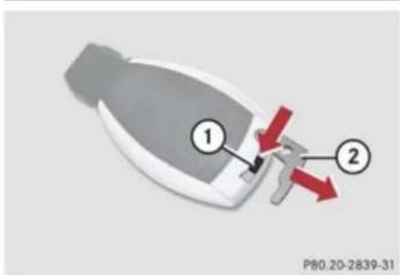
text_image
① ② P80.20-2839-31① Mechanical key locking tab
② Mechanical key
▶ Move locking tab ① in direction of arrow.
▶ Slide mechanical key ② out of the housing.
Unlocking the driver's door
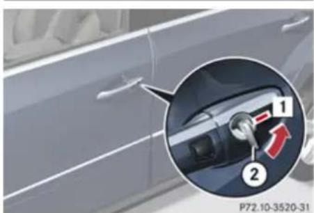
natural_image
Close-up of a car's side panel with a highlighted internal component (no text or symbols visible)1 Unlocking
② Mechanical key
Insert mechanical key ② into the driver's door lock until it stops.
▶ Turn mechanical key ② counterclockwise to position 1 and hold it there.
▶ Pull the door handle until the locking knob moves up.
The driver's door is unlocked.
▶ Pull the door handle once more to open the driver's door.
Locking the vehicle
If you cannot lock the vehicle with the SmartKey or with KEYLESS-GO, lock it as follows:
▶ Close the front passenger door, the right rear door and the tailgate.
- Open the driver's door and the rear left door.
▶ Press the central locking switch (▷ page 89).
The locking knobs of the front passenger door and the rear doors move down.
If the vehicle battery is disconnected or drained: Press down the locking knobs of the front passenger door and the rear doors manually.
▶ Exit the vehicle.
▶ Close the driver's door.
▶ Enter the vehicle through the rear left door.
- Press down the locking knob of the driver's door.
! To prevent inadvertent lockout, make sure to have the SmartKey with you before proceeding with the next step. The next step will lock the vehicle.
Practical hints
▶ Exit the vehicle.
▶ Close the rear left door.
The vehicle is locked.
This procedure does not arm the anti-theft alarm system, nor does it lock the fuel filler flap.
Fuel filler flap

Warning!
Avoid contact with the vehicle walls as they may contain sharp edges. Otherwise, you could injure yourself while releasing the fuel filler flap.
In case the central locking system does not release the fuel filler flap, you can open it manually.
The fuel filler flap release is located behind a cover in the right side trim panel of the cargo compartment.
▶ Open the tailgate (▷ page 90).
▶ Remove right side trim panel (▷ page 393).
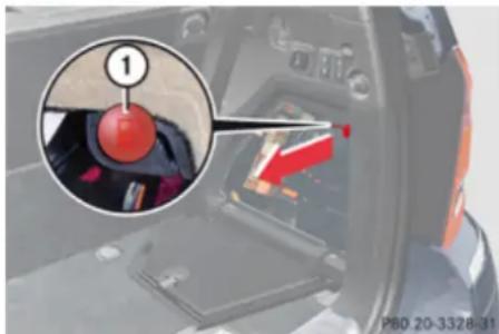
text_image
1 P80 20-3326-31① Fuel filler flap release
▶ Pull red fuel filler flap release ① in direction of arrow.
The fuel filler flap is unlocked.
▶ Open the fuel filler flap (▷ page 265).
Resetting activated head restraints
Resetting activated head restraints
If the active head restraints have been triggered in a rear-end collision, the active head restraints must be reset.
You can tell that the active head restraints have been triggered when they have been moved forward and cannot be adjusted.
Warning!
For safety reasons, have the active head restraints checked at an authorized Mercedes-Benz Center after a rear-end collision.
Warning!
When pushing back the head restraint cushion, make sure your fingers do not become caught between the head restraint cushion and the cover. Failing to do so may lead to injury.
i Pressing the head restraint cushion back requires high force. If you encounter difficulties when pushing the head restraint back, please have the procedure performed at an authorized Mercedes-Benz Center.
Practical hints
Replacing SmartKey batteries
For your convenience, we recommend that you have this work carried out at an authorized Mercedes-Benz Center.
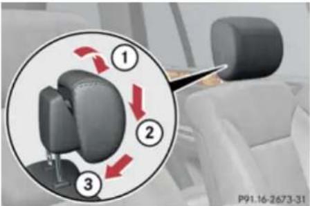
text_image
1 2 3 P91.16-2673-31① Pull
② Adjust downward
③ Press
▶ Pull the top of the head restraint cushion in direction of arrow ① as far as it will go.
▶ Adjust the head restraint cushion downward in direction of arrow ② as far as it will go.
▶ Firmly press the top of the active head restraint cushion towards the head
restraint cover in direction of arrow ③ until it engages.
▶ Repeat this procedure on the active head restraint for the second front seat.
For information on active head restraints, see "Active head restraints" (▷ page 66).
Replacing SmartKey batteries
If the batteries in the SmartKey are discharged, the vehicle can no longer be locked or unlocked. It is recommended to have the batteries replaced at an authorized Mercedes-Benz Center.
Warning!
Batteries contain poisonous and corrosive substances. Therefore, keep the batteries out of reach of children.
If a battery is swallowed, seek medical help immediately.
Warning
SmartKey batteries contain perchlorate material, which may require special handling and regard for the environment. Check with your local government's disposal guidelines. California residents, see www.dtsc.ca.gov/HazardousWaste/Perchlorate/index.cfm.
Batteries contain materials that can harm the environment if disposed of improperly. Recycling of batteries is the preferred method of disposal. Many states require sellers of batteries to accept old batteries for recycling.
Practical hints
Replacing SmartKey batteries
When inserting the batteries, make sure they are clean and free of lint.
When replacing batteries, always replace both batteries.
i The required replacement batteries are available at any authorized Mercedes-Benz Center.
Replacement batteries: Lithium, type CR 2025 or equivalent.
▶ Remove the mechanical key from the SmartKey (▷ page 384).
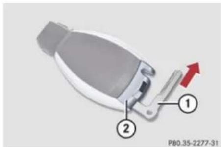
text_image
P80.35-2277-31① Mechanical key
② Battery compartment
▶ Insert mechanical key ① into opening.
▶ Press mechanical key ① in direction of arrow.
Battery compartment ② is unlatched.
▶ Pull battery compartment ② out of the SmartKey housing.
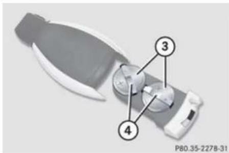
text_image
P80.35-2278-31③ Batteries
④ Contact springs
▶ Pull out batteries ③.
▶ Insert new batteries ③ under contact springs ④ with the positive terminal (+) side facing up.
▶ Return battery compartment ② into SmartKey housing until it locks into place.
▶ Slide mechanical key ① back into the SmartKey.
▶ Check the operation of the SmartKey as well as the KEYLESS-GO function.
Practical hints
Replacing bulbs
Replacing bulbs
Safety notes
Safe vehicle operation depends on proper exterior lighting and signaling to a large degree.
Correct headlamp adjustment is extremely important. Have headlamps checked and readjusted at regular intervals and when a bulb has been replaced. Contact an authorized Mercedes-Benz Center for headlamp adjustment.

Warning!
Bulbs and bulb sockets can be very hot. Allow the lamp to cool down before changing a bulb.
Keep bulbs out of reach of children.
Halogen lamps contain pressurized gas. A bulb can explode if you:
- touch or move it when hot
- drop the bulb
- scratch the bulb
Wear eye and hand protection.
Because of high voltage in Xenon lamps, it is dangerous to replace the bulb or repair
the lamp and its components. We recommend that you have such work done by a qualified technician.
If the headlamps or front fog lamps are fogged up on the inside as a result of high humidity, driving the vehicle a distance with the lights on should clear up the fogging.
Bulbs
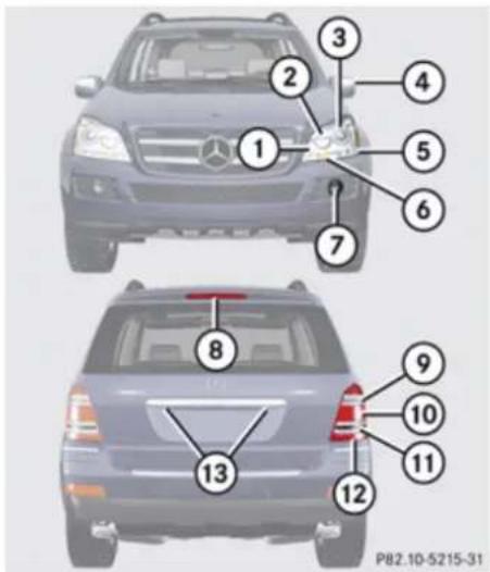
text_image
1 2 3 4 5 6 7 8 9 10 11 12 13 P82.10-5215-31Practical hints
Replacing bulbs
Front lamps
| Lamp Type | ||
| 1 | Parking and standing lamp | W 5 W |
| 2 | Halogen headlamp: High-beam lamp/High-beam flasher lamp | H7 (55 W) |
| Bi-Xenon headlamp: High-beam flasher lamp/High-beam flasher spot lamp | H7 (55 W) | |
| 3 | Halogen headlamp: Low beam | H7 (55 W) |
| Bi-Xenon headlamp: Low and high beam ^17 | D1S-35 W | |
| 4 | Additional turn signal lamp | LED |
| 5 | Side marker lamp WY 5 W |
| Lamp Type | |
| 6 Turn signal lamp 3457 AK | S-8 |
| 7 Front fog lamp H11 (55 W) | |
| Corner-illuminating front fog lamp | H11 (55 W) |
Rear lamps
| Lamp Type | ||
| 8 | High-mounted brake lamp | LED |
| 9 | Backup lamp P 21 W | |
| 10 | Tail lamp, parking and standing lamp, brake lamp, side marker lamp | P 21 W |
| 11 | Turn signal lamp PY 21 W |
| Lamp Type | ||
| 12 | Rear fog lamp (driver's side only) | P 21 W |
| 13 | License plate lamps C 5 W |
Notes on bulb replacement
- Only use 12 volt bulbs of the same type and with the specified watt rating.
- Switch the lights off before changing a bulb to prevent short circuits.
• Always use a clean lint-free cloth when handling bulbs. - Your hands should be dry and free of oil and grease.
- If the newly installed bulb does not come on, contact an authorized Mercedes-Benz Center.
! Do not replace the LEDs yourself. You could otherwise damage the LEDs or parts of the vehicle. Only have the LEDs replaced at an authorized Mercedes-Benz Center.
Practical hints
Replacing bulbs
Replacing bulbs for front lamps
Before you start to replace a bulb for a front lamp, do the following:
▶ Switch off the ignition.
▶ Turn the exterior lamp switch to position 0.
▶ Open the hood (▷ page 267).
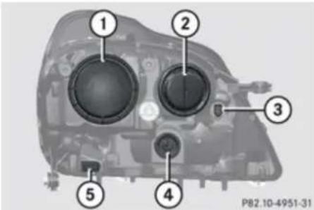
text_image
① ② ③ ④ ⑤ P82.10-4951-31① Housing cover for low-beam halogen or Bi-Xenon headlamp
② Housing cover for high-beam halogen bulb (high beam and high-beam flasher)
③ Bulb socket for parking and standing lamp bulb
④ Bulb socket for front turn signal lamp bulb
⑤ Bulb socket for side marker lamp bulb
Warning!
Do not remove the cover for the Bi-Xenon headlamp. Because of high voltage in Xenon lamps, it is dangerous to replace the bulb or repair the lamp and its components. It is recommended to have such work done by a qualified technician.
Low-beam bulb (halogen headlamps only)
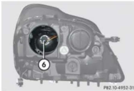
natural_image
Interior view of a mechanical device with labeled component (6), no visible text or symbols beyond the number and date⑥ Bulb socket for low-beam headlamp
▶ Turn housing cover ① counterclockwise and remove it.
▶ Turn bulb socket ⑥ with the bulb counterclockwise and remove it.
▶ Pull the bulb out of bulb socket ⑥.
▶ Gently press the new bulb into bulb socket ⑥.
▶ Place bulb socket ⑥ back into the housing and turn it clockwise until it engages.
▶ Align housing cover ① and turn it clockwise until it engages.
High-beam and high-beam flasher bulb (halogen headlamps)/high-beam flasher bulb (Bi-Xenon headlamps)
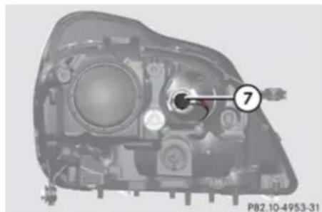
natural_image
Internal view of a mechanical component with numbered annotation (7), no readable text or symbols beyond the label⑦ Bulb socket for high-beam headlamp
▶ Turn housing cover ② counterclockwise and remove it.
▶ Turn bulb socket ⑦ with the bulb counterclockwise and remove it.
▶ Pull the bulb out of bulb socket ⑦.
Practical hints
Replacing bulbs
▶ Gently press the new bulb into bulb socket ⑦.
▶ Place bulb socket ⑦ back into the housing and turn it clockwise until it engages.
▶ Align housing cover ② and turn it clockwise until it engages.
Parking and standing lamp bulb, front turn signal lamp bulb, side marker lamp bulb
▶ Turn respective bulb socket ③, ④ or ⑤ (> page 390) with the bulb counterclockwise and remove it.
▶ Pull the bulb out of the bulb socket.
▶ Gently press the new bulb into the bulb socket.
Place bulb socket ③, ④ or ⑤ back into the housing and turn it clockwise until it engages.
Removing front fog lamp cover
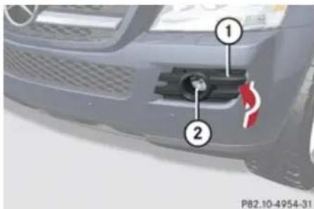
text_image
1 2 P82.10-4954-31① Cover
② Front fog lamp or corner-illuminating front fog lamp
Insert a suitable object (e.g. a screwdriver) at point indicated by the arrow and pry out cover ①.
Cover ① is released.
▶ Swing cover ① outwards and take it off.
Accessing and replacing the front fog lamp bulb
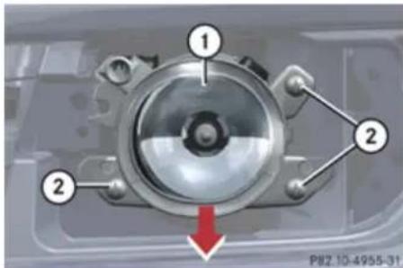
text_image
1 2 2 PI82 10-4955-31① Front fog lamp
② Retaining screws
▶ Remove retaining screws ②.
Remove front fog lamp ① from the bumper.
▶ Pull electrical connector off.
Front fog lamp bulb
! If not done carefully and properly, damage to the bumper can result. It is recommended to have this work carried out at an authorized Mercedes-Benz Center.
Practical hints
Replacing bulbs
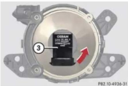
text_image
CRISRAM 1713 000-000 P82.10-4936-31③ Bulb socket for front fog lamp bulb
▶ Turn bulb socket ③ with the bulb counterclockwise and remove it.
▶ Pull the bulb out of bulb socket ③.
▶ Gently press the new bulb into bulb socket ③.
Place bulb socket ③ back into the housing and turn it clockwise until it engages.
▶ Plug in the electrical connector.
▶ Insert front fog lamp ① into bumper.
▶ Fasten retaining screws ②.
▶ Reinsert the cover and press it in until it engages.
Replacing bulbs for rear lamps
Before you start to replace a bulb for a rear lamp, do the following:
▶ Switch off the ignition.
▶ Turn the exterior lamp switch to position 0.
Tail lamp unit
To access the tail lamp units, you first have to remove the cover in the corresponding side trim panel of the cargo compartment.
▶ Open the tailgate.
Opening the driver's side trim panel

natural_image
Interior view of a car showing the door panel with numbered callouts (1 and 2), no visible text or symbols beyond labels.① Lock
② Cover
▶ Turn lock ① by 90° in direction of the arrow.
Remove cover ②.
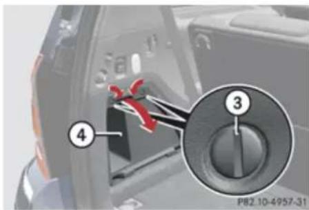
text_image
P82 10-4957-31③ Lock
④ Storage compartment
Remove everything from storage compartment ④.
▶ Insert a suitable object such as a coin into the slot of lock ③.
▶ Turn lock ③ by 90^ in direction of the arrow.
▶ Remove storage compartment ④.
Practical hints
Replacing bulbs
Opening the passenger side trim panel
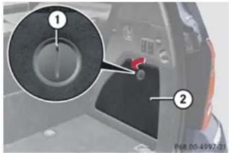
text_image
Diagram showing a device's power button with labeled parts, including a magnified inset highlighting the key component.① Lock
② Cover
▶ Insert a suitable object such as a coin into the slot of lock ①.
▶ Turn lock ① by 90^ in direction of the arrow.
Remove cover ②.
Replacing bulbs
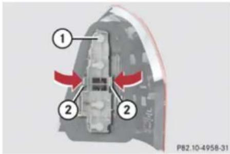
text_image
① ② ② P82.10-4958-31Example illustration rear lamp driver's side
① Bulb socket
② Clamp
▶ Press and hold clamps ②.
▶ Pull bulb socket ① outwards.
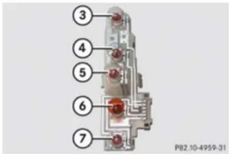
text_image
③ ④ ⑤ ⑥ ⑦ P82.10-4959-31Bulb socket
③ Backup lamp
④ Tail lamp, brake lamp, parking and standing lamp
⑤ Tail lamp, brake lamp, parking and standing lamp
⑥ Rear turn signal lamp
⑦ Rear fog lamp (driver's side only)
▶ Depending on which bulb needs to be replaced, gently press onto the respective bulb and turn it counterclockwise out of bulb socket ①.
▶ Gently press the new bulb into bulb socket ① and turn it clockwise until it engages.
▶ Align bulb socket ① and press it into rear lamp until it audibly engages.
Practical hints
Replacing bulbs
▶ Make sure bulb ① socket is attached properly.
▶ Close the respective cover in the cargo compartment.
▶ Close the tailgate.
License plate lamps
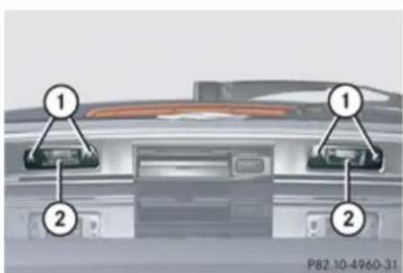
text_image
① ① ② ② P82.10-4960-31① Screws
② Lamp cover
▶ Loosen screws ① of lamp cover to be removed.
▶ Remove lamp cover ②.
▶ Replace the bulb.
▶ Reinstall lamp cover ②.
▶ Retighten screws ①.
Adjusting headlamp aim
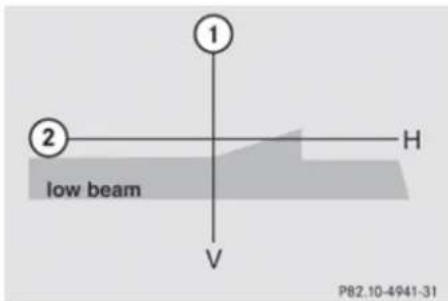
text_image
1 2 low beam V H P82.10-4941-31① V Vertical centerline
② H Horizontal mounting height, measured from the center
Correct headlamp adjustment is extremely important. High beam adjustments simultaneously aim the low beam. To check and readjust a headlamp, follow the steps described:
▶ Park the vehicle on a level surface 25 feet (7.6 m) from a vertical test screen or wall.
▶ Make sure the vehicle has a normal tailgate load.
▶ Switch on the low beam headlamps
If the beam does not show a beam pattern as indicated in the figure left, then follow the steps below:
▶ Open the hood (▷ page 267).
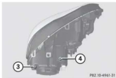
text_image
P82.10-4961-31Example illustration headlamp driver'side
③ Headlamp vertical adjustment screw
④ Headlamp vertical adjustment screw
▶ Always turn adjustment screws ③ and ④ simultaneously for vertical adjustment until the headlamp is adjusted as shown in ①. Turn clockwise for upward movement and counterclockwise for downward movement.
Graduations:
- Screw ③: 0.50^ pitch
- Screw ④: 0.67^ pitch
Practical hints
Replacing wiper blades
The left and right headlamps must be adjusted individually.
If it is not possible to obtain a proper headlamp adjustment, have the system checked at an authorized Mercedes-Benz Center.
Replacing wiper blades
Safety notes
Warning!
For safety reasons, switch off wipers and remove SmartKey from starter switch (vehicles with KEYLESS-GO: Make sure the vehicle's on-board electronics have status 0) before replacing a wiper blade. Otherwise, the wiper motor could suddenly turn on and cause injury.
Warning!
Wiper blades are components that are subject to wear and tear. Replace the wiper blades twice a year, preferably in the spring and fall. Otherwise the windows will not be properly wiped. As a result, you may not be able to observe surrounding traffic conditions and could cause an accident.
! Never open the hood when a front wiper arm is folded forward.
Hold on to the wiper when folding a wiper arm back. If released, the force of the impact from the tensioning spring could crack the windshield or the rear window.
Do not allow a wiper arm to contact the windshield glass or the rear window without a wiper blade inserted.
Mercedes-Benz recommends that you have this work carried out at an authorized Mercedes-Benz Center.
▶ Remove the SmartKey from the starter switch.
Vehicles with KEYLESS-GO:
▶ Make sure the vehicle's on-board electronics have status 0 (▷ page 96).
Removing wiper blades
Front wiper blades
! Do not pull on the wiper blade inserts. They could tear.
▶ Fold the wiper arms forward until they engage.
Practical hints
Replacing wiper blades
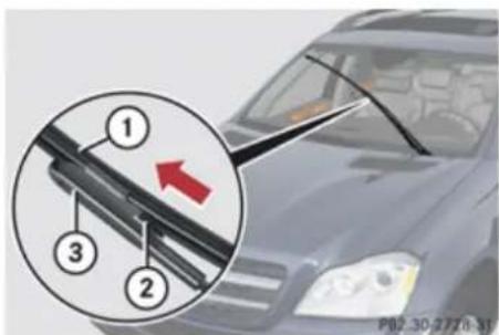
text_image
1 2 3 P82-30-277a:51① Wiper blade
② Tab
③ Wiper arm
▶ Press tabs ② together.
▶ Tilt wiper blade ① away from wiper arm ③.
▶ Take off wiper blade ① in direction of arrow.
Rear wiper blade
! Do not pull on the wiper blade insert. It could tear.

text_image
Diagram showing a car's steering wheel and keyway with numbered parts, including a magnified inset highlighting the wheel's direction.① Wiper arm
② Wiper blade
▶ Fold wiper arm ① away from the rear window until it engages.
▶ Turn wiper blade ② as far as it will go.
▶ Hold wiper arm ① and disengage wiper blade ② by carefully sliding it in direction of arrow.
Remove wiper blade ②.
Installing wiper blades
Front wiper blades
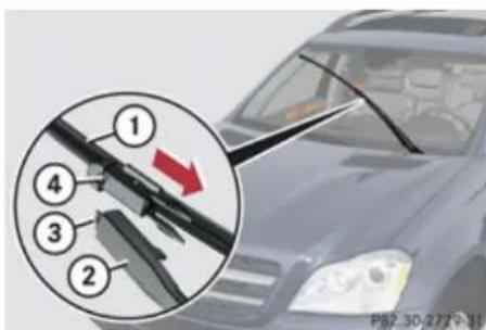
text_image
① ④ ③ ② P87.30-277V-11① Wiper blade
② Attachment
③ Guide tab
④ Opening
▶ With guide tab ③ sliding into opening ④, place wiper blade ① onto wiper arm in direction of arrow.
▶ Fold wiper blade ① towards wiper arm. Tabs ② (> page 396) must engage into both recesses of attachment ②.
Practical hints
Flat tire
▶ Check whether the wiper blade is securely fastened.
▶ Fold the wiper arm backward to rest on the windshield.
Make sure you hold on to the wiper arm when folding it back.
! Make sure the wiper blades are properly installed. Improperly installed wiper blades may cause windshield damage.
Rear wiper blade
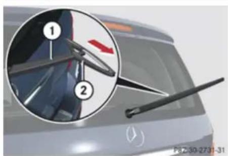
text_image
Diagram showing a car's wheel assembly with numbered parts and a magnified view highlighting the wheel's rotation direction.① Wiper arm
② Wiper blade
▶ Insert wiper blade ② into wiper arm ①.
▶ Hold wiper arm ① and engage wiper blade ② by pushing it in direction of arrow until it locks into place.
▶ Check whether the wiper blade is securely fastened.
▶ Fold the wiper arm to rest on the rear window.
Make sure to hold on to the wiper when folding the wiper arm back.
! Make sure the wiper blade is properly installed. An improperly installed wiper blade may cause rear window damage.
Flat tire
Safety notes
Your vehicle may be equipped with an MOExtended system or a Minispare wheel. Vehicles with an MOExtended system do not have a spare wheel.
For information on your vehicle's equipment, see "Rims and tires" (▷ page 425).
Warning!
The dimensions of the spare wheel are different from those of the road wheels. As a result, the vehicle handling characteristics change when driving with a spare wheel mounted. Adapt your driving style accordingly.
The spare wheel is for temporary use only. When driving with spare wheel mounted, ensure proper tire inflation pressure and do not exceed a vehicle speed of 50 mph (80 km/h).
Contact the nearest authorized Mercedes-Benz Center as soon as possible to have the spare wheel replaced with a regular road wheel.
Never operate the vehicle with more than one spare wheel mounted.
▶▶
Practical hints
Flat tire
Do not switch off the ESP ^® when a spare wheel is mounted.

Warning!
Your vehicle is equipped with air suspension program. Do not open or close any doors or the tailgate while mounting a spare wheel. The vehicle could rise or lower to a previously selected level. You or others could be injured as a result.
Preparing the vehicle
▶ Make sure the vehicle level is set to highway level (> page 186).
▶ Park the vehicle in a safe distance from moving traffic on a hard, flat surface when possible.
▶ Turn on the hazard warning flasher.
▶ Turn the steering wheel so that the front wheels are in a straight-ahead position.
▶ Engage the parking brake.
▶ Shift the automatic transmission into park position P.
▶ Turn off the engine.
Remove the SmartKey from the starter switch.
or
▶ Vehicles with KEYLESS-GO: Open the driver's door (this puts the starter switch in position 0, same as with the SmartKey removed from the starter switch). The driver's door can then be closed again. Open doors only when conditions are safe to do so.
▶ Vehicles with KEYLESS-GO: Remove the KEYLESS-GO start/stop button from the starter switch.
▶ Have any passenger exit the vehicle at a safe distance from the roadway. Open doors only when conditions are safe to do so.
Mounting the spare wheel
Introduction
Prepare the vehicle as described (▷ page 398).
▶ Take the following out of the vehicle:
- spare wheel
- jack
- wheel wrench
• collapsible wheel chock
- alignment bolt
For information on where to find the respective items, see "Where will I find ...?" (▷ page 326) and (▷ page 329).
Lifting the vehicle

Warning!
When jacking up the vehicle, only use the jack which has been specifically approved by Mercedes-Benz for your vehicle.
The jack is designed exclusively for jacking up the vehicle at the jack take-up brackets built into both sides of the vehicle. Make sure the jack arm is fully seated in the jack
Practical hints
Flat tire
take-up bracket. The jack must always be vertical when in use, especially on inclines or declines.
The jack is intended only for lifting the vehicle briefly for wheel changes. It is not suited for performing maintenance work under the vehicle. To help avoid personal injury, use the jack only to lift the vehicle during a wheel change.
Never get beneath the vehicle while it is supported by the jack. Keep hands and feet away from the area under the lifted vehicle. Always lower the vehicle onto sufficient capacity jackstands before working under the vehicle.
Always firmly set the parking brake and block the wheels with wheel chocks or other sizeable objects before raising the vehicle with the jack. Do not disengage the parking brake while the vehicle is raised.
Make sure that the ground on which the vehicle is standing and where you place the jack is solid, level and not slippery. If necessary, use a large underlay. On slippery surfaces, such as tiled floors, you should use a non-slip underlay, for example a rubber mat.
Do not use wooden blocks or similar objects to support the jack. Otherwise the jack may not be able to achieve its load-bearing capacity if it is not at its full height. Never start the engine when the vehicle is raised.
Also observe the notes on the jack.
▶ Prevent the vehicle from rolling away by blocking wheels with wheel chocks or other sizeable objects.
One wheel chock is included with the vehicle tool kit (▷ page 326). For information on setting up the collapsible wheel chock, see (▷ page 328).
Warning!
Only jack up the vehicle on level ground or on slight inclines/declines. Otherwise, the vehicle could fall off the jack and injure you or others.
Changing wheel on a level surface
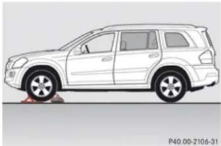
natural_image
Side profile illustration of a white SUV with red accents, shown from front and side (no text or symbols on the vehicle itself)Changing rear wheel on passenger side (example illustration)
Place the wheel chock in front of and another sizeable object behind the wheel that is diagonally opposite to the wheel being changed.
Changing wheel on a slight decline
Always try lifting the vehicle using the jack on a level surface. However, should circumstances require you to do so on a slight decline, place the wheel chock and another sizeable object as follows:
▶▶
Practical hints
Flat tire
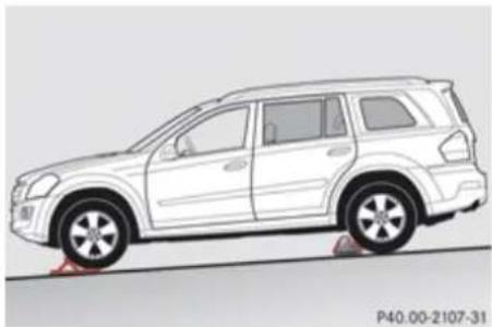
natural_image
Side profile illustration of a white SUV on a road, showing suspension and wheelbase (no text or symbols)Changing wheel on passenger side (example illustration)
Place the wheel chock and another sizeable object in front of both wheels on the side opposite to the side on which the wheel is to be changed.
Changing wheel on a slight incline
Always try lifting the vehicle using the jack on a level surface. However, should circumstances require you to do so on a slight incline, place the wheel chock and another sizeable object as follows:
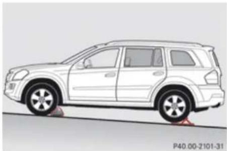
natural_image
Side profile illustration of a white SUV on a road, showing front and rear views with no text or symbols.Changing wheel on passenger side (example illustration)
Place the wheel chock and another sizeable object in behind both wheels on the side opposite to the side on which the wheel is to be changed.
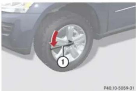
natural_image
Close-up of a car tire with red arrow indicating clockwise motion (no text or symbols)① Wheel wrench
On wheel to be changed, loosen but do not yet remove the wheel bolts (approximately one full turn with wrench ①).
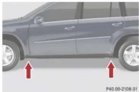
natural_image
Side view of a dark SUV with two red arrows pointing to the side of the wheel (no text or symbols on the car itself)The jack take-up brackets are located directly behind the front wheel housings and in front of the rear wheel housings.
Warning!
The jack is designed exclusively for jacking up the vehicle at the jack take-up brackets. Make sure the jack arm is fully seated in the jack take-up bracket.
If you do not position the jack correctly in the jack take-up bracket, the vehicle can fall off the jack and seriously or fatally injure you or others.
Practical hints
Flat tire
! Do not position the jack on the body of the vehicle, as this may cause damage to the vehicle.
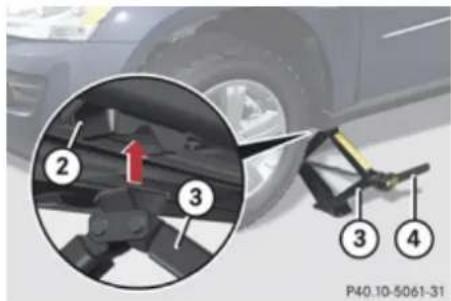
text_image
P40.10-5061-31② Take-up bracket
③ Jack
④ Ratchet
▶ Attach reversible ratchet ④ to jack ③ in such a way that the word UP can be seen.
▶ Place jack ③ on firm ground.
▶ Position jack ③ under take-up bracket ② so that it is always vertical as seen from the side, even if the vehicle is parked on an incline.
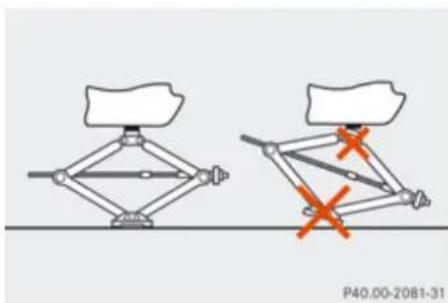
natural_image
Diagram showing two mechanical linkage configurations with red X marks indicating failure or failure points (no text or symbols present)▶ Turn ratchet ④ up and down until jack ③ is fully seated in take-up bracket ② and the jack base evenly meets the ground
Jack up the vehicle until the wheel is a maximum of 1.2 in (3 cm) from the ground.
Removing the wheel
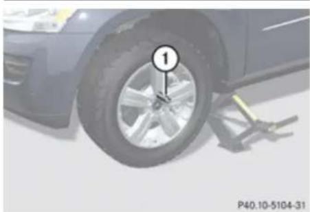
natural_image
Close-up of a car tire mounted on a lift, with a numbered annotation pointing to the wheel (no text or symbols on the tire itself)① Alignment bolt
▶ Unscrew uppermost wheel bolt and remove it.
▶ Replace this wheel bolt with alignment bolt
① supplied with the vehicle tool kit.
▶ Remove the remaining bolts.
! Do not place wheel bolts in sand or dirt. This could result in damage to the wheel bolts and wheel hub threads.
▶ Remove the wheel.
Practical hints
Flat tire
Attaching the spare wheel

Warning!
Always replace wheel bolts that are damaged or rusted.
Never apply oil or grease to wheel bolts. Damaged wheel hub threads should be repaired immediately. Do not continue to drive under these circumstances! Contact an authorized Mercedes-Benz Center or call Roadside Assistance.
Incorrect wheel bolts or improperly tightened wheel bolts can cause the wheel to come off. This could cause an accident. Be sure to use the correct wheel bolts.

Warning!
Only use genuine Mercedes-Benz wheel bolts. Other wheel bolts may come loose. Do not tighten the wheel bolts when the vehicle is raised. Otherwise the vehicle could fall off the jack.
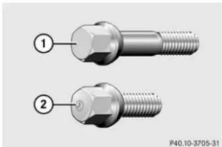
natural_image
Two metallic bolts with hexagonal end caps, labeled 1 and 2 (no text or symbols on the bolts themselves)① Wheel bolt for 19", 20", and 21" light alloy wheels
② Wheel bolt for Minispare wheel (located in vehicle tool kit)
! Wheel bolts ② must be used when mounting the Minispare wheel. The use of any wheel bolts other than wheel bolts ② for the Minispare wheel will damage the vehicle's brakes.

Warning!
Make sure to use the original length wheel bolts when remounting the original wheel after it has been repaired.
▶ Clean contact surfaces of wheel and wheel hub.
! To avoid paint damage, place wheel flat against hub and hold it there while installing first wheel bolt.
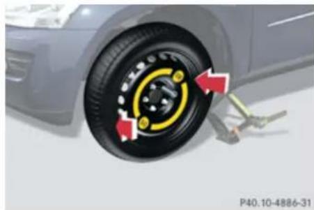
natural_image
Close-up of a car tire with red arrows indicating mechanical adjustment or repair (no text or symbols)▶ Guide the spare wheel onto the alignment bolt and push it on.
▶ Insert the wheel bolts and tighten them slightly.
▶ Unscrew the alignment bolt.
▶ Install last wheel bolt and tighten it slightly.
Lowering the vehicle
▶ Attach ratchet to vehicle jack so that the word DOWN can be seen.
Practical hints
Flat tire
Lower the vehicle until the vehicle is resting fully on its own weight:
▶ Turn ratchet in direction DOWN.
▶ Remove the jack.
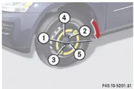
text_image
1 2 3 4 5 P40.10-5201-31① - ⑤ Wheel bolts
▶ Tighten the five wheel bolts evenly, following the diagonal sequence illustrated (① to ⑤), until all bolts are tight. Observe a tightening torque of 110 lb-ft (150 Nm).
Warning!
Have the tightening torque checked after changing a wheel. The wheels could come loose if they are not tightened to a torque of 110 lb-ft (150 Nm).
▶ Fully collapse the jack to storage position, see (▷ page 329).
▶ Store the jack and the other vehicle tools in the designated storage space.
For information on storing the spare wheel after it has been replaced by a regular road wheel, see (▷ page 329).
The damaged road wheel cannot be stored in the spare wheel well under the cargo compartment floor. It should be transported in the cargo compartment wrapped in a protective wrap.
i Vehicles with TPMS:
Do not restart the tire inflation pressure monitor until a full size wheel/tire with functioning sensor has been placed back into service on the vehicle.
MOExtended system
The MOExtended system allows you to continue driving your vehicle even if there is a total loss of pressure in one or more tires. You may only use the MOExtended system in conjunction with the Run Flat Indicator (▷ page 282) or the TPMS (▷ page 283).
The maximum distance in emergency mode depends on the vehicle's load. It is 30 miles (50 km) if the vehicle is partially loaded and 18 miles (30 km) if the vehicle is fully loaded. The point at which the maximum driving distance in emergency mode begins is when the warning message appears in the multifunction display indicating that there is a loss of tire inflation pressure.
▶ Do not exceed the maximum speed of 50 mph (80 km/h).
Warning!
In emergency mode, your vehicle's driving characteristics are diminished in such situations as:
- driving around curves
- while braking
• while accelerating rapidly
Practical hints
Bleeding the fuel system (diesel engine only)
Therefore, your driving style must be adapted accordingly. Avoid abrupt steering and driving maneuvers, as well as driving over obstacles (road curbs, potholes, or off-road areas). This is especially important if the vehicle is heavily loaded.
The emergency driving distance that can be achieved greatly depends on the demands placed on the vehicle. Depending on speed, load, driving maneuvers, road conditions, outside temperature, etc., the distance can be significantly shorter or, if the vehicle is driven cautiously, somewhat longer.
Do not continue driving in emergency mode if
• you notice knocking sounds
• the vehicle starts to shake
• smoke develops and you smell rubber
- ESP® is intervening continuously
- you notice tears on the tire sidewalls
After driving in emergency mode, you must have the rims inspected by an authorized Mercedes-Benz Center to check if they are suitable for further use. The failed tire must be replaced in any case.
When replacing individual or all tires on the vehicle, make sure only tires marked with
"MOExtended" are mounted in the size specified for your vehicle (▷ page 425).
Bleeding the fuel system (diesel engine only)
Driving the vehicle until the fuel tank is empty is not recommended. Otherwise, air may be sucked into the fuel system. If this happens, the malfunction indicator lamp check engine (USA only) or 📋 (Canada only) comes on and the engine may not start immediately after refueling the vehicle.
After refueling:
▶ Make sure the automatic transmission is in park position P.
The gear position indicator in the multifunction display should be on P.
▶ Do not depress the accelerator.
▶ If necessary, remove the KEYLESS-GO start/stop button from the starter switch.
▶ Turn the SmartKey in the starter switch to position 2 for at least 10 seconds.
▶ Return the SmartKey in the starter switch to position 0.
▶ Turn the SmartKey in the starter switch to position 3 and hold it there for a maximum of 40 seconds or until the engine runs surge-free.
If the engine does not start:
Practical hints
AdBlue ^® (diesel engine only)
▶ Wait for approximately 2 minutes.
▶ Turn the SmartKey in the starter switch to position 3 and hold it there for a maximum of 40 seconds or until the engine runs surge-free.
If the engine still does not start, do not make any further attempts to start the engine. Contact an authorized Mercedes-Benz Center or call Roadside Assistance ( page 253).
When the malfunction indicator lamp
check engine (USA only) or 📄 (Canada only) in the instrument cluster has been illuminated for the above condition, it will remain illuminated until the engine was cycled on and off four times in a row.
AdBlue ^® (diesel engine only)
The BlueTEC exhaust gas aftertreatment system requires a reducing agent (AdBlue ^® ) in order to function properly. Refilling with AdBlue ^® is part of the regular maintenance service work. A tankful of AdBlue ^® should suffice until the next maintenance service under normal driving conditions.
When the AdBlue ^® tank is low, the message Check Additive see Operator's Manual appears in the multifunction display.
When the AdBlue ^® level drops to the minimum level, the message Remaining Starts: 20 appears in the multifunction display.
When the message Remaining Starts: 20 appears in the multifunction display, you can start the engine 20 more times. If you do not add AdBlue ^® , the engine cannot be started beyond that point. Fill the AdBlue ^® tank with approximately 1 gal (3.79 l) AdBlue ^® (corresponds to approximately 2 AdBlue ^® refill containers) or have the AdBlue ^® tank filled by an authorized Mercedes-Benz Center.
For refilling outside the maintenance service intervals, refill the AdBlue ^® tank with approximately 1 gal (3.79 l) AdBlue ^® (corresponds to approximately 2 AdBlue ^® refill containers).
Always use the particular AdBlue ^® refill containers for refilling outside the maintenance service interval. Contact an authorized Mercedes-Benz Center or call Roadside Assistance if necessary (▶ page 253).
Additional information on BlueTEC exhaust gas aftertreatment and AdBlue ^® is available at any authorized Mercedes-Benz Center.
Refilling with AdBlue®
Warning!
Make sure
- AdBlue ^ does not come into contact with skin, eyes, or clothing
• to keep AdBlue ^® out of the reach of children
Practical hints
AdBlue® (diesel engine only)
If you and/or others have come into contact with AdBlue®:
- If AdBlue ^ has gotten into contact with eyes, flush with plenty of water immediately and seek medical help.
- Clean affected skin immediately with plenty of water.
- If AdBlue® was swallowed, rinse mouth immediately with plenty of water and drink plenty of water. Consult a physician.
Warning!
When opening the filler cap of the AdBlue ^® tank ammonia gas vapors may escape. Refill AdBlue ^® in a well ventilated area only. Ammonia gas vapors have a pungent odor and are particularly irritating for your skin, mucous membranes, and eyes. Inhaling ammonia gas vapors will cause burning eyes, nose, and throat, as well as coughing and watering eyes.
! Only use AdBlue® complying with ISO 22241. Do not add additives to AdBlue® and do not dilute AdBlue® with
water. Otherwise, the BlueTEC exhaust gas aftertreatment system could be damaged. Damage caused by using additives or diluting with water are not covered by the Mercedes-Benz Limited Warranty.
! Rinse surfaces that have come into contact with AdBlue ^® , or remove AdBlue ^® with a moist cloth and cold water immediately. If AdBlue ^® has crystallized already, use cold water and a sponge. AdBlue ^® residues will crystallize and soil the affected surfaces.
! AdBlue ^® is not a fuel additive and must not be added to the diesel fuel tank. If AdBlue ^® reaches the diesel fuel tank, the engine could be damaged which is not covered by the Mercedes-Benz Limited Warranty.
For more information on AdBlue ^® , see ( page 437).
The AdBlue ^® filler neck is located under the cargo compartment floor.
▶ Switch off the ignition.
▶ Open the tailgate (▷ page 90).
▶ Lift the cargo compartment floor (▷ page 327).
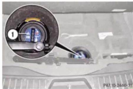
natural_image
Close-up of a car's engine compartment with a magnified inset showing the wheel and valve (no text or symbols visible)① AdBlue ^® filler cap cover
▶ Turn cover ① counterclockwise and remove it.
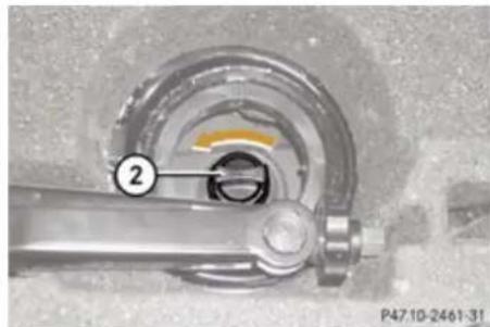
natural_image
Mechanical assembly diagram showing a rotating shaft and housing with a highlighted section (no text or symbols)② AdBlue ^® filler cap
Practical hints
AdBlue ^® (diesel engine only)
▶ Turn filler cap ② counterclockwise and open it. Filler cap ② is tethered with a plastic strap.
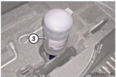
natural_image
Close-up of a mechanical component with a numbered label (3) and no visible text or symbols on the main subject.③ AdBlue ^® refill container
▶ Pull dust cap off of AdBlue ^® refill container ③.
Place AdBlue® refill container ③ on the filler neck as illustrated and tighten it moderately (hand-tight) by turning it clockwise.
! Make sure to tighten the AdBlue® refill container only moderately, i.e. hand-tight, as you could otherwise damage it.
▶ Push AdBlue ^® refill container ③ down.
The AdBlue ^® tank is filled. This may take up to 1 minute.
When you stop pushing the AdBlue ^® refill container down, the filling process is stopped and you can remove the refill container.
▶ Release AdBlue ^® refill container ③.
▶ Turn AdBlue ^® refill container ③ counterclockwise and remove it.
Place filler cap ② (▷ page 406) on filler neck and turn it clockwise.
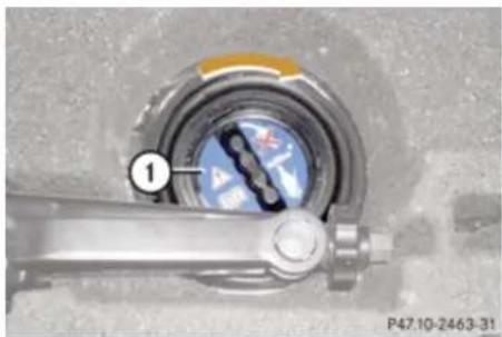
natural_image
Close-up of a mechanical component with a circular dial and labeled part (1), no readable text or symbols beyond the label.① AdBlue ^® filler cap cover
▶ Place cover ① as illustrated and turn it clockwise to its stop.
▶ Start the engine.
i If the message Check Additive See Operator's Manual still appears in the multifunction display, refill with one more container of AdBlue®.
▶ Lower cargo compartment floor.
▶ Close the tailgate.
i Have the AdBlue® level checked and, if necessary, filled completely afterward at an authorized Mercedes-Benz Center.
Practical hints
Battery
Battery
Safety notes
A battery should always be sufficiently charged in order to achieve its rated service life. Refer to Maintenance Booklet for battery maintenance intervals.
If you use your vehicle mostly for short-distance trips, you will need to have the battery charge checked more frequently. When replacing a battery, always use a battery approved by Mercedes-Benz.
If you do not intend to operate your vehicle for an extended period of time, contact an authorized Mercedes-Benz Center about steps you need to observe.

Warning!
Observe all safety instructions and precautions when handling automotive batteries.

Risk of explosion.

Fire, open flames and smoking are prohibited when handling batteries. Avoid creating sparks.

Battery acid is caustic. Do not allow it to come into contact with skin, eyes or clothing.
Wear suitable protective clothing, especially gloves, apron and faceguard.

Wear eye protection. Rinse any acid spills immediately with clear water. Contact a physician if necessary.
Keep children away.

Follow the instructions in this Operator's Manual.
Batteries contain materials that can harm the environment if disposed of improperly. Large 12-volt storage batteries contain lead. Recycling of batteries is the preferred method of disposal. Many states (USA only) or provinces (Canada only) require sellers of batteries to accept old batteries for recycling.

Warning!
Failure to follow these instructions can result in severe injury or death.
Never lean over batteries while connecting. You might get injured.
Battery fluid contains sulfuric acid. Do not allow this fluid to come in contact with eyes, skin or clothing. In case it does, immediately flush affected area with water and seek medical help if necessary.
A battery will also produce hydrogen gas, which is flammable and explosive. Keep flames or sparks away from battery, avoid improper connection of jumper cables, smoking etc.

Warning!
Do not place metal objects on the battery as this could result in a short circuit.
Use leak-proof batteries only to avoid the risk of acid burns in the event of an accident.

The battery is a Valve-Regulated Lead Acid (VRLA) battery, also referred to as "fleece" battery.
Such batteries do not require topping-up of the electrolyte level. VRLA batteries
Practical hints
Battery
therefore do not have cell caps and the battery cover is non-removable. Do not attempt to open the battery as otherwise the battery will be damaged.
Even though VRLA batteries do not require topping-up of the electrolyte level and cannot be opened to check the electrolyte level, the battery condition must be checked periodically by performing a battery conductance test. Refer to Maintenance Booklet for battery condition testing intervals.
The factory-equipped VRLA battery is leak-proofed. Only use a battery as replacement that has the same security features and is of identical size, voltage, and capacity as the factory-equipped battery.
As with any other battery, have the battery disconnect at a qualified workshop or an authorized Mercedes-Benz Center if you do not intend to operate your vehicle for an extended period of time to prevent battery discharge. You may also connect an accessory battery charge unit expressly approved by Mercedes-Benz for your vehicle model to maintain the battery charge. Contact an authorized Mercedes-Benz Center for further information.
The battery, the battery ventilation hose and the lateral plug must always be securely installed when the vehicle is in operation.
! Never loosen or detach battery terminal clamps while the engine is running or the SmartKey is in the starter switch or KEYLESS-GO button is in position 1. Otherwise the alternator and other electronic components could be severely damaged.
Have the battery checked regularly at an authorized Mercedes-Benz Center.
Refer to Maintenance Booklet for maintenance intervals or contact an authorized Mercedes-Benz Center for further information.
i After battery power was interrupted, do the following:
- Set the clock (▷ page 160).
Vehicles with COMAND system with navigation module: Time and date are set automatically. -
Synchronize the door windows (▷ page 126).
-
Synchronize the power tilt/sliding sunroof (▷ page 226).
- Synchronize the exterior rear view mirrors (▷ page 112).
Charging the battery
Warning!
Never charge a battery while still installed in the vehicle unless the accessory battery charge unit approved by Mercedes-Benz is being used. Gases may escape during charging and cause explosions that may result in paint damage, corrosion or personal injury.
An accessory battery charge unit specially adapted for Mercedes-Benz vehicles and tested and approved by Mercedes-Benz is available, permitting the charging of the battery in its installed position. Contact an authorized Mercedes-Benz Center for information and availability.
Charge battery in accordance with the separate instructions for the accessory battery charger.
Have batteries charged at an authorized Mercedes-Benz Center. If you charge the
Practical hints
Jump starting
batteries yourself, follow the operating instructions for your charging device.
Only use a battery charge unit with a maximum charging voltage of 14.8 V.
▶ Charge battery in accordance with the instructions of the battery charger manufacturer.
Jump starting
Warning!
Failure to follow these directions will cause damage to the electronic components, and can lead to a battery explosion and severe injury or death.
Never lean over batteries while connecting or jump starting. You might get injured.
Battery fluid contains sulfuric acid. Do not allow this fluid to come in contact with eyes, skin or clothing. In case it does, immediately flush affected area with water, and seek medical help if necessary.
A battery will also produce hydrogen gas, which is flammable and explosive. Keep flames or sparks away from battery, avoid improper connection of jumper cables, smoking, etc.
Attempting to jump start a frozen battery can result in it exploding, causing personal injury.
Read all instructions before proceeding.
transmission which is not covered by the Mercedes-Benz Limited Warranty.
! Jump starting should only be performed using the jump-start terminals located in the engine compartment.
Avoid repeated and lengthy starting attempts.
Do not attempt to start the engine using a battery quick-charge unit.
If the engine does not run after several unsuccessful starting attempts, have it checked at the nearest authorized Mercedes-Benz Center.
Excessive unburned fuel generated by repeated failed starting attempts may damage the catalytic converter ^18 and may present a fire risk.
Make sure the jumper cables do not have loose or missing insulation.
Make sure the cable clamps do not touch any other metal part while the other end is still attached to a battery.
! Do not tow-start the vehicle. You could otherwise seriously damage the automatic
Practical hints
Jump starting
If the battery is discharged, the engine can be started with jumper cables and the battery of another vehicle. Observe the following:
- Jump starting should only be performed when the engine and catalytic converter ^19 are cold.
- Do not start the engine if the battery is frozen. Let the battery thaw out first.
- Only jump start from batteries with the same voltage rating (12 V). Jump starting with a more powerful battery could damage the vehicle's electrical system, which will not be covered by the Mercedes-Benz Limited Warranty.
- Only use jumper cables with sufficient cross-section and insulated terminal clamps.
• Always make sure the jumper cables are not on or near pulleys, fans or other parts that move when an engine is started or running.
The jump-start contacts are located in the engine compartment on the passenger side.
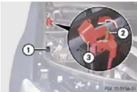
text_image
Diagram showing a mechanical assembly with numbered components and an inset close-up of a component, likely from an engineering or manufacturing context.① Negative terminal
② Positive terminal
③ Positive terminal cover
▶ Make sure the two vehicles do not touch.
▶ Switch off all electrical consumers.
▶ Engage the parking brake.
▶ Make sure the automatic transmission is in park position P.
▶ Open the hood.
▶ Flip up cover ③ of positive terminal ② in direction of arrow.
▶ Remove cover from negative terminal ①.
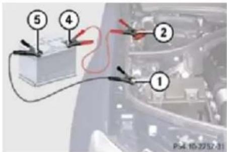
text_image
① ② ③ ④ ⑤ P54 10-2257-31① Negative terminal
② Positive terminal
④ Positive terminal of charged battery
⑤ Negative terminal of charged battery
! Never invert the terminal connections!
Connect positive terminal ④ of the charged battery with positive terminal ② with a jumper cable. Clamp the cable to positive terminal ④ of the charged battery first.
▶ Start engine of the vehicle with the charged battery and run at idle speed.
Connect negative terminal ⑤ of the charged battery with negative terminal ① with a jumper cable. Clamp the cable to
Practical hints
Towing the vehicle
negative terminal ⑤ of the charged battery first.
▶ Start engine of the vehicle with the discharged battery and run at idle speed. You can now turn on the electrical consumers. Do not switch on the headlamps under any circumstances.
Remove the jumper cables first from negative terminals ① and ⑤ and then from positive terminals ② and ④. You can now switch on the headlamps.
▶ Have the battery checked at the nearest authorized Mercedes-Benz Center.
Towing the vehicle
Safety notes
Mercedes-Benz recommends that the vehicle be transported with all wheels off the ground using flatbed or appropriate wheel lift/dolly equipment. This method is preferable to other types of towing.
! To prevent damage during transport, do not tie down vehicle by its chassis or suspension parts.
If circumstances do not permit the recommended towing methods, the vehicle may be towed with all wheels on the ground only so far as necessary to have the vehicle moved to a safe location where the recommended towing methods can be employed.
! Before towing the vehicle observe the following instructions:
- Do not tow-start the vehicle. You could otherwise seriously damage the automatic transmission which is not covered by the Mercedes-Benz Limited Warranty.
- Do not tow with sling-type equipment. Towing with sling-type equipment over
bumpy roads will damage radiator and supports.
- Towing of the vehicle should only be done using the properly installed towing eye bolt. Never attach a tow cable, tow rope or tow rod to the vehicle chassis, frame or suspension parts.
! Do not tow with one axle raised. Doing so could damage the transfer case, which is not covered by the Mercedes-Benz Limited Warranty. All wheels must be on or off the ground. Observe instructions for towing the vehicle with all wheels on the ground.
i If the battery is disconnected or discharged
- the SmartKey will not turn in the starter switch
- the automatic transmission will remain in park position P
- For more information see "Battery" (▷ page 408) or "Jump starting" (▷ page 410).
Practical hints
Towing the vehicle
Installing towing eye bolt
Depending on whether you are towing a vehicle or you are being towed, the towing eye bolt can be screwed into threaded holes which are located behind covers on each bumper.
The towing eye bolt is supplied with the vehicle tool kit, located in the cargo compartment underneath the cargo compartment floor (▷ page 326).
▶ Take the towing eye bolt out of the space underneath the cargo compartment floor.
Removing cover in front bumper
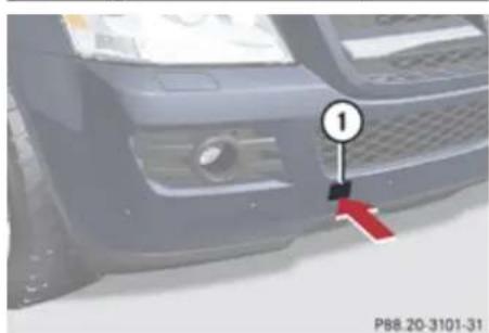
natural_image
Close-up of a car's front bumper with a numbered marker and red arrow pointing to the edge (no text or symbols on the vehicle itself)① Cover
▶ Press mark on cover ① as indicated by the arrow.
▶ Lift cover ① off to reveal the threaded hole for the towing eye bolt.
Removing cover in rear bumper
Warning!
In order to avoid possible serious burns or injury, use extreme caution when removing the rear cover, because the rear exhaust pipe is extremely hot.
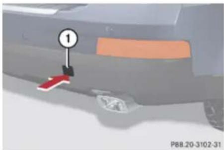
natural_image
Close-up of a car's front bumper with a numbered marker and red accent stripe (no visible text or symbols)① Cover
▶ Press mark on cover ① as indicated by the arrow.
▶ Lift cover ① off to reveal the threaded hole for the towing eye bolt.
Fixing towing eye bolt
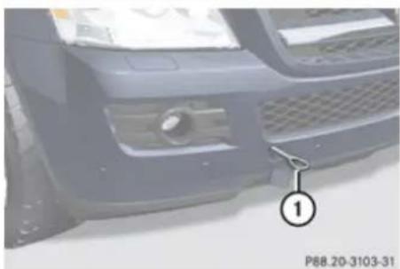
natural_image
Close-up of a car's front bumper with a numbered marker (1) pointing to the grille and side panel, no visible text or symbols on the vehicle itself.Example illustration front bumper
① Towing eye bolt
▶ Take the towing eye bolt ① and the wheel wrench from the vehicle tool kit.
▶ Screw towing eye bolt ① clockwise into threaded hole to its stop.
Insert wheel wrench into towing eye and tighten towing eye bolt ① by turning it clockwise.
Practical hints
Towing the vehicle
Removing towing eye bolt
▶ Loosen towing eye bolt ① counterclockwise with wheel wrench.
▶ Unscrew towing eye bolt ①.
▶ Reinstalling cover: Engage cover ① (▶ page 413) at top and press at bottom.
▶ Store the towing eye bolt and wheel wrench back into the vehicle tool kit.
Towing with all wheels on the ground

Warning!
If circumstances require towing the vehicle with all wheels on the ground, always tow with a tow bar if:
• the engine will not run
- there is a malfunction in the brake system
- there is a malfunction in the power supply or in the vehicle's electrical system
This is necessary to adequately control the towed vehicle.
Prior to towing the vehicle with all wheels on the ground, make sure the SmartKey is in starter switch position 2.

Warning!
With the engine not running, there is no power assistance for the brake and steering systems. In this case, it is important to keep in mind that a considerably higher degree of effort is necessary to brake and steer the vehicle. Adapt your driving accordingly.
▶ Make sure the ignition is switched on.
▶ With the vehicle at a standstill, depress the brake pedal and keep it pressed.
▶ Shift the automatic transmission into neutral position N.
▶ Release the brake pedal.
▶ If engaged, release the parking brake.
▶ Switch on the hazard warning flasher (▷ page 118).
! Keep in mind that it is important to have the ignition switched on. Removing the SmartKey from the starter switch or opening a front door with the ignition switched off will automatically shift the
automatic transmission into park position P.
! The vehicle may be towed only for distances up to 30 miles (50 km) and at a speed not to exceed 30 mph (50 km/h).
To signal turns while being towed with the hazard warning flasher in use you can activate the combination switch for the left or right turn signal in the usual manner – only the selected turn signal will operate. Upon canceling the turn signal, the hazard warning flasher will operate again.
Stranded vehicle
Freeing a stranded vehicle, on which the wheels are dug into sand or mud, should be done with the greatest of care, especially if the vehicle is heavily loaded.
Practical hints
Fuses
Note the following when freeing a stranded vehicle:
- Avoid pulling the vehicle abruptly or diagonally, since it could result in damage to the chassis alignment.
- Never try to free a vehicle that is still coupled to a trailer.
- If possible, a vehicle equipped with a trailer hitch receiver should be pulled backward in its own previously made tracks.
Fuses
Introduction
The electrical fuses in your vehicle serve to switch off malfunctioning power circuits. If a fuse is blown, the components and systems secured by that fuse will stop operating.
Warning!
Only use fuses approved by Mercedes-Benz with the specified amperage for the system in question and do not attempt to repair or bridge a blown fuse. Using other than approved fuses or using repaired or bridged fuses may cause an overload leading to a fire, and/or cause damage to electrical components and/or systems. Have the cause determined and remedied by an authorized Mercedes-Benz Center.
A blown fuse must be replaced by an appropriate spare fuse (recognizable by its color or the fuse rating given on the fuse) of the amperage recommended in the fuse chart. Any Mercedes-Benz Center will be glad to advise you on this subject.
In case of a blown fuse contact Roadside Assistance or an authorized Mercedes-Benz Center.
If a newly inserted fuse blows again, have the cause determined and rectified by an authorized Mercedes-Benz Center.
A fuse chart is located in the cargo compartment with the vehicle tool kit (▷ page 326). The fuse chart explains the fuse allocation and fuse amperages.
Before replacing fuses
▶ Engage the parking brake.
▶ Make sure the automatic transmission is in park position P.
The transmission position indicator in the multifunction display should be on P.
▶ Switch off all electrical consumers.
▶ Turn off the engine.
▶ Remove the SmartKey from the starter switch.
▶ Vehicles with KEYLESS-GO: Open the driver's door (this puts the starter switch in position 0, same as with the SmartKey removed from the starter switch). The driver's door then can be closed again.
Practical hints
Fuses
Fuse box in passenger compartment
! Do not use sharp objects such as a screwdriver to open the fuse box cover in the dashboard. You could damage the fuse box cover or the dashboard.
The fuse box is located behind a cover in the dashboard on the front passenger side.
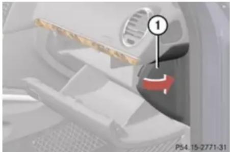
natural_image
Close-up of a car interior showing a red arrow pointing to a component, with no visible text or symbols.① Fuse box cover
▶ Opening: Open the front passenger door.
▶ Open the glove box.
▶ Insert flat, blunt object as a lever into the edge of cover ① at the position indicated by the arrow.
▶ Loosen cover ① from the dashboard using the lever.
▶ Using your hands, pull cover ① out and remove.
▶ Closing: Hook cover ① into the opening at the front.
▶ Press cover ① back on until it engages.
! The fuse box cover must be properly positioned as described to prevent moisture or dirt from entering the fuse box and possibly impairing fuse operation.
Fuse box in engine compartment
▶ Opening: Open the hood.
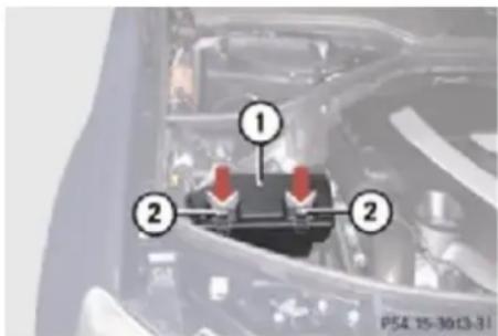
text_image
Diagram of a vehicle engine compartment with numbered parts and red arrows indicating featuresExample illustration fuse box GL 450 (GL 320 BlueTEC, GL 550 similar)
① Fuse box cover
② Clamps
▶ With a dry cloth, remove any moisture from the fuse box ①.
▶ Pull clamps ② in direction of arrow.
▶ Lift fuse box cover ① up.
▶ Closing: Make sure the sealing rubber is positioned properly.
▶ Press fuse box cover ① down and secure with clamps ②.
! The fuse box cover must be installed properly to prevent moisture and/or dirt from entering the fuse box and possibly impairing fuse operation.
- Close the hood after checking or replacing fuses.
Practical hints
Fuses
Fuse box in cargo compartment
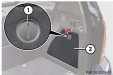
text_image
Diagram of a vehicle's door panel with labeled parts and a magnified inset showing the dial indicator.① Lock
② Cover
▶ Opening: Open the cargo compartment.
▶ Insert a suitable object such as a coin into the slot of lock ①.
▶ Turn lock ① by 90^ in direction of arrow.
Remove cover ②.
▶ Closing: Install cover ② in reverse order.
Emergency engine shutdown
If the engine cannot be turned off as described ( page 133), you may use the following emergency procedure.
▶ Take the fuse chart from the vehicle tool kit (▷ page 326).
▶ Open the fuse box in engine compartment.
▶ Remove fuse 120.
Find its location in the fuse chart.
Technical data
Vehicle equipment 420
Parts service 420
Warranty coverage 420
Identification labels 421
Engine 423
Rims and tires 425
Electrical system 429
Main dimensions 430
Weights 431
Fuels, coolants, lubricants etc. ..... 432

natural_image
Gray gear icon with an exclamation mark in the center, no text or symbols present.Technical data
Warranty coverage
Vehicle equipment
This Operator's Manual describes all features, standard or optional, potentially available for your vehicle at the time of purchase. Please be aware that your vehicle might not be equipped with all features described in this manual.
Parts service
All authorized Mercedes-Benz Centers maintain a stock of Genuine Mercedes-Benz Parts required for maintenance and repair work. In addition, strategically located parts distribution centers provide quick and reliable parts service.
More than 300 000 different parts for Mercedes-Benz models are available. Genuine Mercedes-Benz Parts are subjected to stringent quality inspections. Each part has been specifically developed, manufactured or selected for and adapted to Mercedes-Benz vehicles.
Therefore, Genuine Mercedes-Benz Parts should be installed.
! Do not use non-genuine Mercedes-Benz parts and accessories not authorized by Mercedes-Benz. Doing so could damage the vehicle, which is not covered by the Mercedes-Benz Limited Warranty. Also, it could compromise the vehicle's durability or safety.
Warranty coverage
Your vehicle is covered under the terms of the warranties printed in the Service and Warranty Information booklet.
Your authorized Mercedes-Benz Center will exchange or repair any defective parts originally installed in the vehicle in accordance with the terms of the following warranties:
- New Truck Limited Warranty
- Emission System Warranty
- Emission Performance Warranty
- California, Connecticut, Maine, Massachusetts, New York, Pennsylvania, Rhode Island, and Vermont Emission Control Systems Warranty ^20
• State Warranty Enforcement Laws (Lemon Laws)
Replacement parts and accessories are covered by the Mercedes-Benz Parts and Accessories warranties, copies of which are available at any authorized Mercedes-Benz Center.
Technical data
Identification labels
Loss of Service and Warranty Information booklet
Should you lose your Service and Warranty Information booklet, have an authorized Mercedes-Benz Center arrange for a replacement. It will be mailed to you.
Identification labels
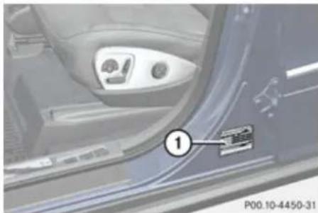
natural_image
Close-up of a car interior showing the dashboard and seat area, with a numbered annotation pointing to a component (no readable text or symbols)① Certification label (on driver's door B-pillar)
The Vehicle Identification Number (VIN) can be found in the following locations:
• on the certification label
- embossed underneath the passenger-side second-row seat (▷ page 422)
- on the lower edge of the windshield (▷ page 422)

text_image
MFD BY MERCEDES-BENZ U.S. INTL., INC TURCALOOSA COUNTY, ALABAMA (USAL UNDER) CONTRACT FOR DAMLER AG, STUTSANT (GOMMANY) 10/07 C172 NO LR TREED SIZE COLD KPN (KPN) GAME FRONT 1470 3240 265/60 R18 8.0x18 220(32) GAME REAR 1800 3968 265/60 R18 8.0x18 260(38) GWHR 3150 6944 THIS VEHICLE CONFORMS TO ALL APPLICABLE FEDERAL MOTOR VEHICLE SAFETY STANDARD IN EFFECT ON THE DATE OF MANUFACTURE SHOWN ITEMS. WDCGF76E07A223811—3 MPV P00.01-3604-31Example certification label (U.S. vehicles)
② Paintwork code
③ VIN
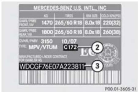
text_image
MERCEDES-BENZ U.S. INT'L., INC KG TIRES 8M SIZE COLD KPN/PSI LAWR/PBNE FRONT / AW 1470 265/60 R18 8.0x18 220(32) LAWR/PBNE REAR / AW 1800 265/60 R18 8.0x18 260(38) CVRW/RPNBV 3150 10/07 TYPE: MPV/VTUM C172 MANUFACTURED LINDER CONTRACT FOR DAMLER AG WDCGF76E07A223811- ② ③ P00.01-3605-31Example certification label (Canada vehicles)
② Paintwork code
③ VIN
Technical data
Identification labels
Data shown on certification label are for illustration purposes only. These data are specific to each vehicle and may vary from data shown in the illustration. Refer to certification label on vehicle for actual data specific to your vehicle.
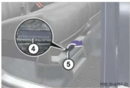
text_image
Diagram showing a vehicle interior with labeled parts and a magnified inset highlighting a specific area.Passenger-side second-row seat
④ VIN
⑤ Carpet
▶ Fold carpet ⑤ forward in direction of arrow.
VIN ④ is now visible.
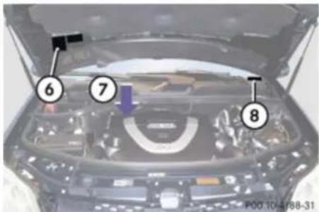
text_image
6 7 8 P00.10-4188-31⑥ Emission control information label, includes both federal and California certification exhaust emission standard
⑦ Engine number (engraved on engine)
⑧ VIN (on lower edge of windshield)
When ordering parts, please specify vehicle identification and engine number.
Technical data
Engine
Engine
| Model | GL 320 BlueTEC (164.825) ^21 | GL 450 (164.871) ^21 | GL 550 (164.886) ^21 |
| Engine 642 273 273 | |||
| Mode of operation | Diesel 4-stroke engine | 4-stroke engine, gasoline injection | 4-stroke engine, gasoline injection |
| No. of cylinders 6 8 8 | |||
| Bore 3.27 in (83.00 mm) 3.66 in (92.90 mm) 3.86 in (98.00 mm) | |||
| Stroke 3.62 in (92.00 mm) 3.39 in (86.00 mm) 3.56 in (90.50 mm) | |||
| Total piston displacement | 182.3 cu in (2 987 cm ^3 ) 284.5 cu in (4 663 cm ^3 ) 333.2 cu in (5 461 cm ^3 ) | ||
| Compression ratio 16.5:1 | 10.7:1 10.7:1 | ||
| Output acc. to SAE J 1349 | 210 hp / 3400 rpm(157 kW / 3400 rpm) | 335 hp / 6000 rpm(250 kW / 6000 rpm) ^22 | 382 hp / 6000 rpm(285 kW / 6000 rpm) ^22 |
| Maximum torque acc. to SAE J 1349 | 400 lb-ft / 1600 rpm - 2400 rpm(543 Nm / 1600 rpm - 2400 rpm) | 339 lb-ft / 2700 rpm - 5000 rpm(460 Nm / 2700 rpm - 5000 rpm) | 391 lb-ft / 2800 rpm - 4800 rpm(530 Nm / 2800 rpm - 4800 rpm) |
| Maximum engine speed | 4500 rpm | 6500 rpm | 6500 rpm |
21 The quoted data apply only to the standard vehicle. Contact an authorized Mercedes-Benz Center for the corresponding data of all special bodies and special equipment.
22 Premium fuel required. Performance may vary with fuel octane rating.
Technical data
Engine
| Model | GL 320 BlueTEC (164.825) ^21 | GL 450 (164.871) ^21 | GL 550 (164.886) ^21 |
| Firing order 1-4-2-5-3-6 1-5-4-2-6-3-7-8 1-5-4-2-6-3-7-8 | |||
| Poly-V-belt | 2035 mm | 2404 mm | 2404 mm |
Technical data
Rims and tires
Rims and tires
Notes
! Only use tires which have been tested and approved by Mercedes-Benz. Tires approved by Mercedes-Benz are developed to provide best possible performance in conjunction with the driving safety systems on your vehicle such as the ABS or the ESP®. Tires specially developed for your vehicle and tested and approved by Mercedes-Benz can be identified by finding the following on the tire's sidewall:
• MO = Mercedes-Benz Original equipment tires
- MOE = Mercedes-Benz_Original_Extended (tires with limited run-flat characteristics) original equipment tires
Using tires other than those approved by Mercedes-Benz may result in damage that is not covered by the Mercedes-Benz Limited Warranty.
For information on driving with MOExtended tires, see the “Practical hints” section (▷ page 403).
i Vehicles with MOExtended system are not factory-equipped with a TREFIT kit.
When retrofitting with tires that do not have run-flat characteristics, e.g. winter tires, you should also equip your vehicle with a TREFIT kit. TREFIT kits are available at any authorized Mercedes-Benz Center.
! Using tires other than those approved by Mercedes-Benz can have detrimental effects, such as
• poor handling characteristics
- increased noise
• increased fuel consumption
Moreover, tires and rims not approved by Mercedes-Benz may, under load, exhibit dimensional variations and different tire deformation characteristics that could cause them to come into contact with the vehicle body or axle parts. Damage to the tires or the vehicle may be the result.
Further information on tires and rims is available at any authorized Mercedes-Benz Center. A placard with the recommended tire inflation pressures is located on the driver's door B-pillar. Some vehicles may have supplemental tire inflation pressure information for driving at high speeds or for vehicle loads less than the maximum
loaded vehicle condition. If such information is provided, it can be found on the placard located on the inside of the fuel filler flap. The tire inflation pressure should be checked regularly and should only be adjusted on cold tires. Follow tire manufacturer's maintenance recommendation included with the vehicle.
For information on recommended tire inflation pressure and supplemental tire inflation pressure information for special driving situations, see ( page 279).
The following pages also list the approved wheel rim and tire sizes for equipping your vehicles with winter tires. Winter tires are not available as standard or optional factory equipment, but can be purchased from an authorized Mercedes-Benz Center. Equipping your vehicle with winter tires approved for your vehicle model may require the purchase of two or four wheel rims of the recommended size for use with these winter tires. This depends on vehicle model and the standard or optional factory-equipped wheel rim/tire configuration on your vehicle. For more information contact an authorized Mercedes-Benz Center.
Technical data
Rims and tires
| Same size tires | ||
| Model GL 450 GL 320 BlueTEC | ||
| Rims (light alloy) 8.5 J x 19 H2 8.5 J x 19 H2 | ||
| Wheel offset 2.20 in (56 mm) 2.20 in (56 mm) | ||
| All-season tires^23 | 275/55 R19 111H M+ S^24 | - |
| Winter tires^23,25 | 265/55 R19 109H M+S | 265/55 R19 109H M+S ^26 |
| All-terrain tires^23,25 | 275/55 R19 111H M+ S^24 | 275/55 R19 111H M+ S^24,26 |
| Rims (light alloy) 8.5 J x 20 H2 8.5 J x 20 H2 | ||
| Wheel offset 2.20 in (56 mm) 2.20 in (56 mm) | ||
| Summer tires^23 | 275/50 R20 109W ^24 | - |
| All season tires^23 | - | 275/50 R20 109H M+S MOExtended ^24,27 |
23 Radial-ply tires
^24 Must not be used with snow chains.
25 Not available as factory equipment.
26 Standard tire without run-flat characteristics. Equipping vehicle with TREFIT is strongly recommended.
27 Must be used in conjunction with Tire Pressure Monitoring System (U.S. vehicles) or Run Flat Indicator (Canada vehicles) only.
Technical data
Rims and tires
| Model GL 450 | GL 550 | GL 550 |
| AMG rims (light alloy) 10 J x 21 H2 – | ||
| Rims (light alloy) – 8.5 J x 19 H2 | ||
| Wheel offset 1.46 in (37 mm) 2.20 in (56 mm) | ||
| All season tires ^28,29 | 295/40 R21 111V XL (Extra Load) M+S – | |
| Winter tires ^28,30 | – 265/55 R19 109H M+S | |
| All-terrain tires ^28,30 | – 275/55 R19 111H M+S |
28 Radial-ply tires
^29 Must not be used with snow chains.
30 Not available as factory equipment.
Technical data
Rims and tires
Spare wheel
! Compare the recommended tire inflation pressure for your vehicle with the tire inflation pressure on the yellow label located on the spare wheel rim.
If the tire inflation pressure on the yellow label on the spare wheel rim differs from the values given in this Operator's Manual, inflate the tire to the recommended tire inflation pressure given on the yellow label on the spare wheel rim.
i Please note that the tire inflation pressure of the spare wheel differs from the tire inflation pressure of the road tires.
The GL 320 BlueTEC does not have a spare wheel.
| Model GL 450 | GL 550 |
| Rim 4.5 B x 19 H2 | |
| Wheel offset 1.58 in (40 mm) | |
| Minispare tire31 | T 165/90 D19 119MorT 165/90 R19 119M |
| Recommended tire inflation pressure 61 psi (4.2 bar) | |
31 Must not be used with snow chains.
Technical data
Electrical system
Electrical system
| Model GL 320 BlueTEC GL 450 | GL 550 | |
| Alternator 14 V / 220 A 14 V / 180 A | ||
| Starter motor 12 V / 2.0 kW 12 V / 1.4 kW | ||
| Battery 12 V / 95 Ah 12 V / 95 Ah | ||
| Spark plugs Type – NGK PLKR 7A | ||
| Electrode gap – 0.031 in (0.8 mm) | ||
| Tightening torque – 15 lb-ft - 18 lb-ft (20 Nm - 25 Nm) |
Technical data
Main dimensions
Main dimensions
| Model GL 450 GL 320 BlueTEC | GL 550 | |
| Overall vehicle length | 200.6 in (5096 mm) | 200.6 in (5096 mm) |
| Overall vehicle width, exterior rear view mirrors folded out | 83.6 in (2124 mm) | 83.6 in (2124 mm) |
| Overall vehicle height, depending on the set vehicle level 72.4 in - 75.6 in(1840 mm - 1920 mm) | 72.4 in - 75.6 in(1840 mm - 1920 mm) | |
| Overall vehicle height, depending on the set vehicle level(vehicles with enhanced off-road package) | 72.4 in - 76.8 in(1840 mm - 1950 mm) | 72.4 in - 76.8 in(1840 mm - 1950 mm) |
| Wheelbase | 121.1 in (3075 mm) | 121.1 in (3075 mm) |
| Track, front | 65.0 in (1651 mm) | 64.8 in (1645 mm) |
| Track, rear | 65.1 in (1654 mm) | 64.9 in (1648 mm) |
| Ground clearance, depending on the set vehicle level 8.0 in - 10.9 in(202 mm - 277 mm) | 8.0 in - 10.9 in(202 mm - 277 mm) | |
| Ground clearance, depending on the set vehicle level(vehicles with enhanced off-road package) | 8.0 in - 12.1 in(202 mm - 307 mm) | 8.0 in - 12.1 in(202 mm - 307 mm) |
| Turning circle 39.7 ft (12.1 m) 39.7 ft (12.1 m) | ||
Technical data
Weights
Weights
Model All models
Roof load max. 198 lb (90 kg)
Technical data
Fuels, coolants, lubricants etc.
Fuels, coolants, lubricants etc.
Capacities
Vehicle components and their respective lubricants must match. Therefore only use products tested and approved by Mercedes-Benz.
For information on tested and approved products, contact an authorized Mercedes-Benz Center or visit www.mbusa.com.
Warning!
Comply with all valid regulations with respect to handling, storing, and disposing of service fluids. Otherwise you could endanger persons or the environment. Keep service fluids out of the reach of children.
For health reasons, you should prevent service fluids from coming into direct contact with your skin or clothing. If a service fluid is swallowed, contact a physician immediately.
| Model Capacity Fuels, coolants, lubricants, etc. | ||
| Engine with oil filter GL 320 BlueTEC | 9.0 US qt (8.5 l) Approved engine oils | |
| GL 550 | ||
| GL 450 9.5 US qt (9.0 l) | ||
| Automatic transmission All models 9.5 US qt (9.0 l) MB Automatic Transmission Fluid | ||
| Front axle All models 1.2 US qt (1.1 l) Hypoid gear oil | ||
| Rear axle All models 1.2 US qt (1.1 l) Hypoid gear oil | ||
| Rear axle with differential lock All models 1.7 US qt (1.6 l) Hypoid gear oil | ||
| Transfer case single speed All models 0.53 US qt (0.5 l) MB Automatic Transmission Fluid | ||
Technical data
Fuels, coolants, lubricants etc.
| Model Capacity Fuels, coolants, lubricants, etc. | |||
| Transfer case double speed All models 1.6 US qt (1.5 l) MB Automatic Transmission Fluid | |||
| Power steering All models approx. 1.3 US qt (1.2 l) MB Power Steering Fluid or approved | Dexron III ATF | ||
| Brake system All models – MB Brake Fluid (DOT 4+) | |||
| Cooling system GL 320 BlueTEC approx. 10.0 US qt (9.5 l) MB 325.0 Anticorrosion/Antifreeze | |||
| Fuel tank, including a reserve of | All models 26.4 US gal (100.0 l) Gasoline engine: | Premium unleaded gasoline (Minimum Posted Octane 91 [Avg. of 96 RON/86 MON])Diesel engine:ULTRA-LOW SULFUR HIGHWAY DIESEL FUEL (15 ppm SULFUR MAXIMUM) | |
| AdBlue®tank | GL 320 BlueTEC 8.3 US gal (31.5 l) | AdBlue® complying with ISO 22241 | |
Technical data
Fuels, coolants, lubricants etc.
| Model Capacity Fuels, coolants, lubricants, etc. | ||
| Air conditioning system All models – R-134a refrigerant and special | PAG lubricant oil (never R-12) | |
| Washer system and headlamp cleaning system | All models 7.6 US qt (7.2 l) MB Windshield Washer | Concentrate ^32 Washer fluid mixing ratio(▷ page 440) |
Approved engine oils
Engine oils are specifically tested for their suitability in our engines and durability for our service intervals. Therefore, only use approved engine oils and oil filters required for vehicles with Maintenance System. For a listing of approved engine oils and oil filters, contact an authorized Mercedes-Benz Center or visit www.mbusa.com (USA only).
! Using engine oils and oil filters of specification other than those expressly required for the Maintenance System, or changing of oil and oil filter at change intervals longer than those called for by the Maintenance System will result in engine or emission control system damage not
covered by the Mercedes-Benz Limited Warranty.
Please follow Maintenance System recommendations for scheduled oil changes. Failure to do so will result in engine or emission control system damage not covered by the Mercedes-Benz Limited Warranty.
Mercedes-Benz recommends MOBIL OIL.
Use the table below to determine the MB sheet number.
| Model Engine | type | MB sheet number |
| GL 320 BlueTEC 642 | 229.51 | |
| GL 450 273 229.5 | ||
| GL 550 273 229.5 |
i MB sheet numbers are printed on the outside of oil containers.
Technical data
Fuels, coolants, lubricants etc.
Viscosity grades for engine oils
Using the chart below, select oil viscosity according to the lowest air temperature expected before the next oil change.
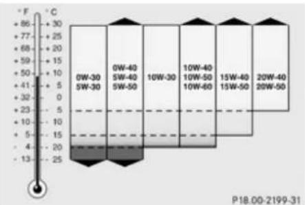
bar
| Temperature Range | Value | | :--- | :--- | | 0W-30 | 30 | | 0W-40 | 30 | | 10W-30 | 30 | | 10W-40 | 30 | | 15W-60 | 30 | | 20W-40 | 30 | | 20W-50 | 30 | P18.00-2199-31Engine oil additives
Do not blend oil additives with engine oil. They may damage the engine. Damage or malfunctions resulting from blending oil additives are not covered by the Mercedes-Benz Limited Warranty.
Air conditioning refrigerant
R-134a (HFC) refrigerant and special PAG lubricating oil are used in the air conditioning system.
! Never use R-12 (CFC) or mineral-based lubricating oil. Otherwise damage to the system will occur.
Brake fluid
Warning!
During vehicle operation, the boiling point of the brake fluid is continuously reduced through the absorption of moisture from the atmosphere.
Under extremely strenuous operating conditions, this moisture content can lead to the formation of bubbles in the system, thus reducing the system's efficiency.
Therefore, the brake fluid must be replaced regularly. Refer to your vehicle's Maintenance Booklet for replacement interval.
Only brake fluid approved by Mercedes-Benz is recommended. Any authorized Mercedes-Benz Center will provide you with additional information.
Premium unleaded gasoline (gasoline engine)
Warning!
Gasoline is highly flammable and poisonous. It burns violently and can cause serious personal injury.
Never allow sparks, flames or smoking materials near gasoline!
Turn off the engine before refueling.
Whenever you are around gasoline, avoid inhaling fumes and any skin or clothing contact. Extinguish all smoking materials.
Direct skin contact with fuels and the inhalation of fuel vapors are damaging your health.
! To maintain the engine's durability and performance, premium unleaded gasoline must be used.
If premium unleaded gasoline is not available and low octane gasoline is used, follow these precautions:
- Have the fuel tank only partially filled with unleaded regular gasoline and fill up
▶▶
Technical data
Fuels, coolants, lubricants etc.
with premium unleaded gasoline as soon as possible.
- Avoid full throttle driving and abrupt acceleration.
- Do not exceed an engine speed of 3000 rpm if the vehicle is loaded with a light load such as two persons and no luggage.
- Do not exceed ^2/_3 of maximum accelerator pedal position if the vehicle is fully loaded or operating in mountainous terrain.
Fuel requirements
Gasoline engine
Only use premium unleaded gasoline. The octane number (posted at the pump) must be 91 min. It is an average of both the Research Octane Number (RON) and the Motor Octane Number (MON): (RON+MON)/2. This is also known as the ANTI-KNOCK INDEX.
Reformulated gasolines (RFG) and/or unleaded gasoline containing oxygenates such as ethanol, TAME, ETBE, IPA, IBA, and TBA can be used provided the ratio of any one of these oxygenates to gasoline does not exceed 10%; MTBE must not exceed 15%. The ratio of methanol to gasoline must not exceed 3% plus additional cosolvents. Using mixtures of ethanol and methanol is not allowed. Gasohol, which contains 10% ethanol and 90% unleaded gasoline, can be used. These blends must also meet all other fuel requirements, such as resistance to spark knock, boiling range, vapor pressure, etc.
Diesel engine
Only use commercially available vehicular ULTRA-LOW SULFUR HIGHWAY DIESEL FUEL (15 ppm SULFUR MAXIMUM). Failure to use ULTRA-LOW SULFUR HIGHWAY DIESEL FUEL can severely damage the vehicle's exhaust after-treatment device.
To prevent malfunctions, diesel fuel with improved cold flow characteristics is offered in the winter months. Check with your fuel retailer.
! Do not fill the tank with gasoline. Do not blend diesel fuel with gasoline or kerosene. The fuel system and engine will otherwise be damaged, which is not covered by the Mercedes-Benz Limited Warranty.
B5 Biodiesel
Mercedes-Benz approves the use of B5 biodiesel (standard diesel with a maximum of up to 5% biodiesel content) in all Common Rail Injection (CDI) and BlueTEC diesel engines. Diesel fuels containing a higher percentage of biodiesel content will cause damage to your engine and are not approved.
As biodiesel can be refined from a variety of raw materials resulting in widely varying properties, the only approved biodiesel content is one that meets ASTM D6751 specification. It must also have the necessary oxidation stability (min. 6h, proved with EN14112 method) to prevent damage to the system from deposits and/or corrosion.
Please ask your service station for further information. If the B5 biodiesel blend is not sufficiently labeled to clearly indicate that it meets the above standards, please do not use it. The Mercedes-Benz Limited Warranty does not cover damage caused by the use of fuels not meeting Mercedes-Benz approved fuel standards.
Technical data
Fuels, coolants, lubricants etc.
Gasoline additives (gasoline engine)
A major concern among engine manufacturers is carbon build-up caused by gasoline. Mercedes-Benz recommends only the use of quality gasoline containing additives that prevent the build-up of carbon deposits.
After an extended period of using fuels without such additives carbon deposits can build up, especially on the intake valves and in the combustion area, leading to engine performance problems such as:
- Warm-up hesitation
- Unstable idle
- Knocking/pinging
- Misfire
- Power loss
In areas where carbon deposits may be encountered due to lack of availability of gasoline which contains these additives, Mercedes-Benz recommends the use of additives approved by us for use on Mercedes-Benz vehicles.
Contact an authorized Mercedes-Benz Center or visit www.mbusa.com (USA only) for a listing of approved product(s). Follow directions on product label.
Do not blend other fuel additives with fuel. This only results in unnecessary cost and may be harmful to the engine operation.
! Damage or malfunction resulting from poor fuel quality or from blending additional fuel additives other than those tested and approved by us for use on Mercedes-Benz vehicles are not covered by the Mercedes-Benz Limited Warranty or by any pre-owned or Extended Limited warranties.
AdBlue®
AdBlue ^® is a non-flammable, non-toxic, colorless and odorless, water-soluble liquid.
! Only use AdBlue® complying with ISO 22241. Do not blend with additives.
! Rinse surfaces that have come into contact with AdBlue ^® , or remove AdBlue ^® with a moist cloth and cold water immediately. If AdBlue ^® has crystallized already, use cold water and a sponge. AdBlue ^® residues will crystallize and soil the affected surfaces.
High ambient temperatures
If AdBlue ^® in the reservoir heats up to above 122°F (50°C) for a long period of time, for example due to direct sunlight, ammonia gas vapors may escape when opening the AdBlue ^® tank.

Warning!
When opening the filler cap of the AdBlue ^® tank ammonia gas vapors may escape. Refill AdBlue ^® in a well ventilated area only. Ammonia gas vapors have a pungent odor and are particularly irritating for your skin, mucous membranes, and eyes. Inhaling ammonia gas vapors will cause burning eyes, nose, and throat, as well as coughing and watering eyes.
Low ambient temperatures
AdBlue ^® freezes at a temperature of approximately 12°F (-11°C). Your vehicle is factory equipped with an AdBlue ^® preheating system. The vehicle can thus be operated at temperatures below 12°F (-11°C).
Technical data
Fuels, coolants, lubricants etc.
Special additives
! Only use AdBlue® complying with ISO 22241. Do not add additives to AdBlue® and do not dilute AdBlue® with water. Otherwise, the BlueTEC exhaust gas aftertreatment system could be damaged. Damage caused by using additives or diluting with water are not covered by the Mercedes-Benz Limited Warranty.
Purity
The purity of AdBlue ^® is of particular importance for avoiding malfunctions in the exhaust gas aftertreatment.
If AdBlue ^® is pumped out of the tank, e.g. during repair work, the same liquid must not be used to refill the tank as its purity is no longer guaranteed.
! Impurities caused for example by other service products, cleaning agents, and dust result in increased emissions, malfunctions, catalyst damage, or engine damage.
Coolants
The engine coolant is a mixture of water and anticorrosion/antifreeze, which provides:
- Corrosion protection
- Freeze protection
- Boiling protection (by increasing the boiling point)
The cooling system was filled at the factory with a coolant providing freeze protection to approximately -35^ F ( -37^ C) and corrosion protection.
! Add premixed coolant solution only. Adding water and MB 325.0 Anticorrosion/Antifreeze separately from each other, could cause engine damage not covered by the Mercedes-Benz Limited Warranty.
If the antifreeze mixture is effective to -35^ ( -37^ ), the boiling point of the coolant in the pressurized cooling system is reached at approximately 266^ ( 130^ ).
The coolant solution must be used year round to provide the necessary corrosion protection and increase boil-over protection. Refer to the Maintenance Booklet for replacement interval.
Coolant system design and coolant used determine the replacement interval. The
replacement interval published in the Maintenance Booklet is only applicable if MB 325.0 Anticorrosion/Antifreeze solution or other Mercedes-Benz approved products of equal specification are used to renew the coolant concentration or bring it back up to the proper level.
For information on other Mercedes-Benz approved products of equal specification, contact an authorized Mercedes-Benz Center or visit www.mbusa.com (USA only).
To provide important corrosion protection, the solution must be at least 50% anticorrosion/antifreeze (equivalent to freeze protection to approximately -35°F [-37°C]).
If you use a solution that is more than 55% anticorrosion/antifreeze (freeze protection to approximately -49°F [-45°C]), the engine temperature will increase due to the lower heat transfer capability of the solution. Therefore, do not use more than this amount of anticorrosion/antifreeze.
If the coolant level is low, water and MB 325.0 Anticorrosion/Antifreeze should be used to bring it up to the proper level (have cooling system checked for signs of leakage). Please make sure the mixture is in accordance with label instructions.
Technical data
Fuels, coolants, lubricants etc.
The water in the cooling system must meet minimum requirements, which are usually satisfied by normal drinking water. If you are not sure about the water quality, contact an authorized Mercedes-Benz Center.
Anticorrosion/antifreeze
Your vehicle contains a number of aluminum parts. The use of aluminum components in
motor vehicle engines necessitates that anticorrosion/antifreeze coolant used in such engines be specifically formulated to protect the aluminum parts. Failure to use such anticorrosion/antifreeze coolant will result in a significantly shortened service life. Therefore, the following product is strongly recommended for use in your vehicle: MB 325.0 Anticorrosion/Antifreeze agent.
Before the start of the winter season (or once a year in hot southern regions), you should have the anticorrosion/antifreeze concentration checked.
The coolant is also regularly checked each time you bring your vehicle to an authorized Mercedes-Benz Center for service.
| Model Approximate freeze protection | ||
| -35°F (-37°C) -49°F (-45°C) | ||
| Cooling system GL 320 BlueTEC 5.0 US qt (4.75 l) 5.5 US qt (5.2 l) | ||
| GL 450 | 6.3 US qt (6.0 l) 7.0 US qt (6.6 l) | |
| GL 550 | ||
Technical data
Fuels, coolants, lubricants etc.
Washer system and headlamp cleaning system
Warning!
Washer solvent/antifreeze is highly flammable. Do not spill washer solvent/antifreeze on hot engine parts, because it may ignite and burn. You could be seriously burned.
Washer fluid mixing ratio
For temperatures above freezing point, use MB Windshield Washer Concentrate "MB SummerFit" and water:
- 1 part "MB SummerFit" to 100 parts water (1.34 fl oz [40 ml] "MB SummerFit" to 1 gal [4.0 l] water)
For temperatures below freezing point, use MB Windshield Washer Concentrate "MB SummerFit" and commercially available premixed washer solvent/antifreeze: - 1 part "MB SummerFit" to 100 parts solvent (1.34 fl oz [40 ml] "MB SummerFit" to 1 gal [4.0 l] solvent)
Service and Literature
Your authorized Mercedes-Benz Center has trained technicians and Genuine Mercedes-Benz Parts to service your vehicle properly. For expert advice and quality service, contact an authorized Mercedes-Benz Center.
If you are interested in obtaining service literature for your vehicle, please contact an authorized Mercedes-Benz Center.
We consider this the best way for you to obtain accurate information for your vehicle.
For further information you can find us on the Mercedes-Benz web-site www.mbusa.com (USA only) or www.mercedes-benz.ca (Canada only).
Therefore, information, illustrations and descriptions in this Operator's Manual might differ from your vehicle.
Reprinting, translation and copying, even of excerpts, is not permitted without our prior authorization in writing.
Press time April 01, 2008
GSP / OIS
Printed in U. S. A.

Warning!
To help avoid personal injury, be extremely careful when performing any service work or repairs. Improper or incomplete service or the use of incorrect or inappropriate parts or materials may damage the vehicle or its equipment, which may in turn result in personal injury.
If you have any questions about carrying out any type of service, turn to the advice of an authorized Mercedes-Benz Center.
We reserve the right to make changes in design and equipment.

1645847182
Order no. 6515 4291 13 Part no. 164 584 71 82 Edition A 2009