
P25 - Security Camera Mobotix - Free user manual and instructions
Find the device manual for free P25 Mobotix in PDF.


| Product Type | Security Camera |
| Brand | Mobotix |
| Model | P25 |
| Sensor | 5 MP CMOS |
| Lens | Interchangeable (C/CS mount) |
| Field of View | 90° (depending on lens) |
| Video Resolution | 5 MP (2592x1944) |
| Frame Rate | 30 fps |
| Video Compression | MJPEG, H.264 |
| Network Interface | Ethernet 10/100/1000 Base-T |
| Audio | Built-in microphone |
| Storage | MicroSD card slot (up to 128 GB) |
| Power Supply | PoE (IEEE 802.3af) or 12V DC |
| Power Consumption | 5W typical |
| Operating Temperature | 0°C to 50°C |
| Dimensions (Diameter) | 120 mm |
| Dimensions (Height) | 94 mm |
| Weight | 1.2 kg |
| Mounting | Wall or ceiling mount |
| Protection Class | IP65 (indoor/outdoor) |
| Night Vision | LED IR up to 30m |
| Motion Detection | Yes, via software |
| Warranty | 2 years |
Frequently Asked Questions - P25 Mobotix
User questions about P25 Mobotix
0 question about this device. Answer the ones you know or ask your own.
Ask a new question about this device
Download the instructions for your Security Camera in PDF format for free! Find your manual P25 - Mobotix and take your electronic device back in hand. On this page are published all the documents necessary for the use of your device. P25 by Mobotix.
USER MANUAL P25 Mobotix
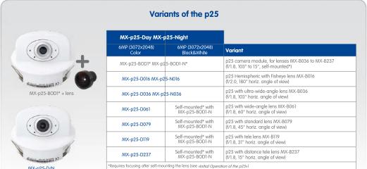
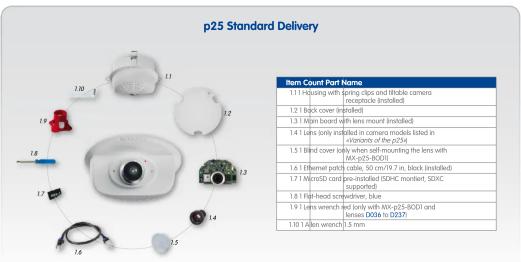
MOBOTIX 6MP camera for flexible use in indoor applications, install as complete Indoor Camera p25 (Day or Night) with selected lenses or as camera module p25 (Day or Night) with separate lens (MX-B036 to MX-B237). www.mobotix.com > Products > p25


![Inserting/Exchanging the SD Card All camera models can use the integrated microSD card (SDXC) to record video data. In order to exchange the microSD card, please proceed as outlined in the following instruction. For information on reliable SD cards, please see the MOBOTIX website www.mobotix.case.+Support > AM Media Library > Planning in the document: MicroSD Card Whitefast for MOBOTIX Cameras. When replacing the SD card, make sure that recording has been deceased in the browser [Admin Menu + Storage] + Storage on External File Server / Flash Device; activate recording again in the same dialog). Follow the instructions in section «Removing/Installing the Back Coven» to access the inside of the camera and to close it again after inserting the SD card.](/content/2026/05/766187/images/f8fc0805a9e86764fadc8b423844de322d6f8f8bffcb76b339cae7b952990fbf.jpg)

Installing the p25
Use the drilling template on the back for this purpose (red circle) or draw a circle with 105 mm/4.13 in diameter for the cut-out. Cut out the hole for the camera, then guide the cables (network cable, USB cable, MxBus and signal input/output wires) through the hole.
1. Install the p25
Press the spring clips back and insert the p25 into the hole for the camera. The spring clips will snap outwards, thus firmly holding the camera in place.
Make sure that you only press back the spring clips as shown in the image. Do not press them back any further as the springs may snap out of their fixtures otherwise.


2. Roughly align the p25
Turn the camera until it roughly points into the intended direction; once it is running, you will adjust the camera according to the live image (see Initial Operation of the p25k.

Removing the p25
1. Pull out the camera
Pull the camera from its position by gently pulling the camera downward on one side, then the other side. Take care to NOT let the spring clips snap forward (risk of injury!).
2. Remove the cables
Remove the cables coming from the building Inetwork cable, USB cable, MxBus and signal input/output wires). Pull out the camera.
Initial Operation of the p25
The initial operation starts with connecting the power supply (see section «Network and Power Connection, Additional Cables» in the M25 Camera Manual). The first access follows the procedure described in the same manual in the section «Initial Operation of the Camera». All other tasks require access to the camera's user interface in the browser. Enter the camera's IP address into the address bar of the browser.
Screw for locking the

1. Set installed lens (only when self-mounting)
Open Admin Menu > Hardware Configuration > Lens Configuration dialog and select the installed lens. This step is required to select the proper special functions of the installed lens (e.g., for wide-angle lenses).
Stick the blue screwdriver
(Item 1.8) into the receptacle for adjusting the camera tilt. Adjust the camera tilt as needed while watching the live image of the camera 1.
Lock the camera tilt by slightly tightening the lock screw 2.

2. Adjust lens focus (if required)
This step is only necessary if the lens has been installed for the first time or exchanged. In cameras with a MX-B016 ("Hemispheric") lens, the lens has been focused at the factory.
Check the live image from the camera in the browser. Activate the focusing aid in the browser (Focusing Aid quick control, Activated value).
4. Configuring and Using the MX-Bus-IO-Module
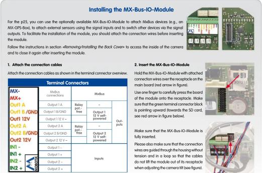
The camera will automatically detect an installed MX-Bus-IO-Module (see Camera Status, System section in browser).
The signal inputs can be used right away in the signal input profiles in the Setup Menu > Event Overview. Likewise, the signal outputs can be used in the signal output profiles in Admin

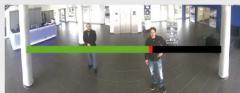
Carefully turn the lens in clockwise or counter-clockwise direction using the red lens wrench until the red area of the focusing aid is as small as possible. Remove the lens wrench every time you changed the lens focus. Once the focus is adjusted properly, deactivate the focusing aid again (Focusing Aid quick control, Disabled value).
In addition, the signal inputs/outputs have been entered automatically in the Admin Menu > Assign Wires dialog and can be used to control doors and lights.
To use one or both signal outputs not as potential-free outputs (for relays), but as self-powered 12 V outputs. open the Admin Menu > Hardware Configuration > Manage Hardware Expansions dialog. In the MxBus/IO Board section, click on Connect for each output you want to use as self-powered output.
3. Adjust viewing direction
Turn the image in the ceiling until the live image shows the desired viewing direction 1. Stick the Allen wrench (item 1.10) into the hole of the lock screw and loosen the screw a bit 2.

5. Save the configuration
In the live image of the browser, select the Manage Settings quick control ans set Store Entire Configuration as value. The camera stores the configuration in the permanent camera memory so that the settings will be applied at the next camera reboot.
Important Notes
Safety Warnings
- This product must not be used in locations exposed to the dangers of explosion.
- Make sure that you install this product as outlined in the installation instructions above.
- When installing this product, make sure that you are only using genuine MOBOTIX parts and MOBOTIX connection cables. - Only install this product in suitable, solid materials that provide for a sturdy installation of the fixing elements used.
- When removing the camera from the ceiling, make sure that the spring clips do not snap back (risk of injury).
- Electrical systems and equipment may only be installed, modified and maintained by a qualified electrician or under the direction and supervision of a qualified electrician in accordance with the applicable electrical guidelines. Make sure to properly set up all electrical connections. - When attaching modules to the USB connector, the power consumption of all attached modules must not exceed 1 W.
- Due to the high performance of the p25, the area of the image sensor can get quite hot, especially when the ambient temperature is also high. This does not affect the proper functioning of the camera in any way. This camera must not be installed within the reach of persons.
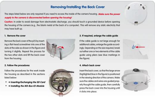
- Make sure the power supply to the camera is disconnected before opening the camera housing (e.g., when exchanging the SD card).
- MOBOTIX products include all of the necessary configuration options for operation in Ethernet networks in compliance with data protection laws. The operator is responsible for the data protection concept across the entire system. The basic settings required to prevent misuse can be configured in the software and are password-protected. This prevents unauthorized parties from accessing these settings.
- Make sure that the operating temperature of 0 to +40 °C/+32 to +104°F is not exceeded.
Legal Notes
You must comply with all data protection regulations for video and sound monitoring when using MOBOTIX products. Depending on national laws and the installation location of the p25, the recording of video and sound data may be subject to special documentation or it may be prohibited. All users of MOBOTIX products are therefore required to familiarize themselves with all valid regulations and comply with these laws. MOBOTIX AG is not liable for any illegal use of its products.
Technical Specifications
Since the p25 is identical to the M25 for the most part, the technical data listed in the M25 Camera Manual Section Technical Data also applies to this product. You can find the M25 Camera Manual as a PDF file on www.mobotix.com > Support > Manuals

| p25 (Differences Compared to M25) | |
| Lens Options | MX-8006 to MX-B237 (100" to 15" hor. angle of view) |
| Max. Image Size | 6MP in 3-2 format (307x204N) |
| Audio Functions | None; optionally with microphone and speaker |
| Interfaces | Ethernet 10/100, IPv4/IPv6, MiniUSB Millilitators inputs/druts using optional MX-Bus-IO-Module |
| Power Consumption | Typ. 4 W |
| Operating Conditions | IP2D (DN IN 60529)0 to 40°C+32 to +104°F (DN IN S0155) |
| Max. Thickness for Installation | Spring clips properly clamp down on materials from 1 to 20 mm/0.4 or 1.1 m |
| Dimensions | Outside diameter 120 mm/4.72 in size, total height 85 mm/12.33, height implied 46 mm/1.81 in, recommended min. installation depth: 50 mm/1.97 in |
| Materials | Housing: RBT G930 |
| Weight | approx. 270 g |
| MX-Bus-IO-Module | |
| Inputs | 2 geionically separated inputs (AC/DC, 41 to 48 V) |
| Outputs | Variant 1 (default): 2 potentiol-free outputs (max. load per pin: max. 30 V or max. 1 A or max. 48 V AC/DC)Variant 2 (set in browser): 2 powered outputs 12 V DC; max. 30 mA per output |
| Add. Interfaces | Mallus connections for MOBOTIX peripheral devices |
| Operating Conditions | Same as camera |
| Cross-sectional area of wires at the terminals | 0.14 mm ^2 – 0.5 mm ^2 (AIVG 21 – 26) |
| Power Consumption | Typ. 0.5 W, max. 1.5 W |

- Installing the p25
- Install the p25
- Roughly align the p25
- Removing the p25
- Pull out the camera
- Remove the cables
- Initial Operation of the p25
- Set installed lens (only when self-mounting)
- Stick the blue screwdriver
- Adjust lens focus (if required)
- Configuring and Using the MX-Bus-IO-Module
- Adjust viewing direction
- Save the configuration
- Important Notes
- Safety Warnings
- Legal Notes
- Technical Specifications
Brand : Mobotix
Model : P25
Category : Security Camera