
GMV-ND36A/A-T(U) - Air-conditioner GREE - Free user manual and instructions
Find the device manual for free GMV-ND36A/A-T(U) GREE in PDF.


| Product Type | Multi-zone Split Air Conditioner (Outdoor Unit) |
| Model | GMV-ND36A/A-T(U) |
| Cooling Capacity | 36,000 BTU/h |
| Heating Capacity | 40,000 BTU/h |
| Energy Efficiency | Inverter; SEER up to 18.5 |
| Power Supply | 208-230V / 60Hz / 1 Phase |
| Dimensions (WxHxD) | 950 x 800 x 340 mm |
| Net Weight | 65 kg |
| Refrigerant Type | R410A |
| Operating Modes | Cool, Heat, Fan, Dry, Auto |
| Airflow Rate (Max) | 1800 CFM |
| Noise Level (Outdoor) | 55 dBA |
| Compressor Type | DC Inverter Rotary |
| Filter Type | Washable Pre-filter |
| Maintenance | Clean filter every 2 weeks; professional service annually |
| Safety Features | Overload protection, auto restart, anti-freeze |
| Spare Parts Availability | Filters, fan motors, PCBs, remote controls available from authorized dealers |
| Warranty | 5 years on compressor, 2 years on parts |
Frequently Asked Questions - GMV-ND36A/A-T(U) GREE
User questions about GMV-ND36A/A-T(U) GREE
0 question about this device. Answer the ones you know or ask your own.
Ask a new question about this device
Download the instructions for your Air-conditioner in PDF format for free! Find your manual GMV-ND36A/A-T(U) - GREE and take your electronic device back in hand. On this page are published all the documents necessary for the use of your device. GMV-ND36A/A-T(U) by GREE.
USER MANUAL GMV-ND36A/A-T(U) GREE
Original Instructions
Commercial Air Conditioners
GMV DC Air Handler
Models:
GMV-ND09A/A-T(U)
GMV-ND12A/A-T(U)
GMV-ND18A/A-T(U)
GMV-ND24A/A-T(U)
GMV-ND30A/A-T(U)
GMV-ND36A/A-T(U)
GMV-ND42A/A-T(U)
GMV-ND48A/A-T(U)
GMV-ND54A/A-T(U)
Thank you for choosing commercial air conditioners. Please read this Owner's Manual carefully before operation and retain it for future reference.
If you have lost the Owner's Manual, please contact the local agent or visit www.gree.com or send an email to global@gree.com.cn for the electronic version.
GREE ELECTRIC APPLIANCES, INC. OF ZHUHAI
Preface
For correct installation and operation, please read all instructions carefully. Before reading the instructions, please be aware of the following items:
(1) For the safe operation of this unit, please read and follow the instructions carefully.
(2) During operation, total capacity of indoor units should not exceed the total capacity of outdoor units. Otherwise, poor effect of cooling or heating may result.
(3) Direct operators or maintainers should well keep this manual.
(4) If this unit fails to operate normally, please contact our service center as soon as possible and provide the following information:
- Content on the nameplate (model number, cooling capacity, production code, ex-factory date).
- Malfunction details (before and after the malfunction occurs).
(5) Each unit has been strictly tested and proved to be qualified before ex-factory. In order to prevent units from being damaged or operating normally because of improper disassembly, please do not disassemble the unit by yourself. If you need to disassemble and check units, please contact our service center. We will send specialists to guide the disassembly.
(6) All graphics in this manual is only for your reference. For sales or production reasons, these graphics are subject to change by manufacturer without prior notice.
User Notice
- This appliance is not intended for use by persons (including children) with reduced physical, sensory or mental capabilities, or lack of experience and knowledge, unless they have been given supervision or instruction concerning use of the appliance by a person responsible for their safety. Children should be supervised to ensure that they do not play with the appliance.
| Correct Disposal of this product | |
 | This marking indicates that this product should not be disposed with other household wastes. To prevent possible harm to the environment or human health from uncontrolled waste disposal, recycle it responsibly to promote the sustainable reuse of material resources. To return your used device, please use the return and collection systems or contact the retailer where the product was purchased. They can take this product for environmental safe recycling. |
| Exception Clauses |
| Manufacturer will bear no responsibilities when personal injury or property loss is caused by the following reasons: |
| (1) Damage the product due to improper use or misuse of the product; |
| (2) Alter, change, maintain or use the product with other equipment without abiding by the instruction manual of manufacturer; |
| (3) After verification, the defect of product is directly caused by corrosive gas; |
| (4) After verification, defects are due to improper operation during transportation of product; |
| (5) Operate, repair, maintain the unit without abiding by instruction manual or related regulations; |
| (6) After verification, the problem or dispute is caused by the quality specification or performance of parts and components that produced by other manufacturers; |
| (7) The damage is caused by natural calamities, bad using environment or force majeure. |
Contents
1 Safety Precautions .... 1
2 Product Introduction....3
2.1 Names of Key Components .... 3
2.2 Rated Working Condition .... 3
3 Preparative for Installation.... 4
3.1 Pre-Installation Instruction....4
3.2 Important Safety Instructions....4
3.3 Requirements for Communication Line ....6
3.4 Wiring Requirements....7
4 Installation Instructions .... 8
4.1 Dimension Data 8
4.2 Location 9
4.3 Piping Work....10
4.4 Condensate Removal.... 11
4.5 Ductwork.... 11
4.6 Installation of Wired Controller 12
5 Wiring Work 12
5.1 Connection of Wire and Patch Board Terminal 12
5.2 Power Cord Connection 13
5.3 Connection of Communication Wire between Indoor Unit and Outdoor Unit (or indoor unit)....13
5.4 Connect Communication Wire of Wired Controller 14
5.5 Illuminate for Connection of Wired Controller and Indoor Units Network 14
6 Routine Maintenance....16
6.1 Cleaning of Filter.... 16
6.2 Maintenance before the Seasonal Use....16
6.3 Maintenance after the Seasonal Use....16
7 Table of Error Codes for Indoor Unit.... 17
1 Safety Precautions
| WARNING |
| (1) This product can't be installed at corrosive, inflammable or explosive environment or the place with special requirements, such as kitchen. Otherwise, it will affect the normal operation or shorten the service life of the unit, or even cause fire hazard or serious injury. As for above special places, please adopt special air conditioner with anti-corrosive or anti-explosion function. |
| (2) Follow this instruction to complete the installation work. Please carefully read this manual before unit (3) startup and service. |
| (4) Wire size of power cord should be large enough.The damaged power cord and connection wire should be replaced by exclusive cable. |
| (5) After connecting the power cord, please fix the electric box cover properly in order to avoid accident. |
| (6) Never fail to comply with the nitrogen charge requirements.Charge nitrogen when welding pipes. |
| (7) Never short-circiut or cancel the pressure switch to prevent unit damage. |
| (8) Please firstly connect the wired controller before energization, otherwise wired controller can not be used. |
| (9) Before using the unit, please check if the piping and wiring are correct to avoid water leakage, refrigerant leakage, electric shock, or fire etc.. |
| (10) Do not insert fingers or objects into air outlet/inlet grille. |
| (11) Open the door and window and keep good ventilation in the room to avoid oxygen deficit when the gas/oil supplied heating equipment is used. |
| (12) Never start up or shut off the air conditioner by means of directly plug or unplug the power cord. |
| (13) Turn off the unit after it runs at least five minutes; otherwise it will influence oil return of the compressor. |
| (14) Do not allow children operate this unit. |
| (15) Do not operate this unit with wet hands. |
| (16) Turn off the unit or cut off the power supply before cleaning the unit, otherwise electric shock or injury may happen. |
| (17) Never spray or flush water towards unit, otherwise malfunction or electric shock may happen. |
| (18) Do not expose the unit to the moist or corrosive circumstances. |
| (19) Under cooling mode, please don't set the room temperature too low and keep the temperature difference between indoor and outdoor unit within 5°C (41°F). |
| (20) User is not allowed to repair the unit. Fault service may cause electric shock or fire accidents. Please contact Gree appointed service center for help. |
| (21) Before installation, please check if the power supply is in accordance with the requirements specified on the nameplate. And also take care of the power safety. |
| (22) Installation should be conducted by dealer or qualified personnel. Please do not attempt to install the unit by yourself. Improper handling may result in water leakage, electric shock or fire disaster etc.. |
| (23) Be sure to use the exclusive accessory and part to prevent the water leakage, electric shock and fire accidents. |
| (24) Make sure the unit can be earthed properly and soundly after plugging into the socket so as to avoid electric shock. Please do not connect the ground wire to gas pipe, water pipe, lightning rod or telephone line. |
| (25) Electrify the unit 8 hours before operation. Please switch on for 8 hours before operation. Do not cut off the power when 24 hours short-time halting (to protect the compressor). |
| (26) If refrigerant leakage happens during installation, please ventilate immediately. Poisonous gas will emerge if the refrigerant gas meets fire. |
| (27) Volatile liquid, such as diluent or gas will damage the unit appearance. Only use soft cloth with a little neutral detergent to clean the outer casing of unit. |
| (28) If anything abnormal happens (such as burning smell), please power off the unit and cut off the main power supply, and then immediately contact Gree appointed service center.If abnormality keeps going, the unit might be damaged and lead to electric shock or fire. |
Any personal injury or property loss caused by improper installation, improper debug, unnecessary repair or not following the instructions of this manual should not be the responsibility of Gree Electric Appliances, Inc. of Zhuhai.
2 Product Introduction
2.1 Names of Key Components
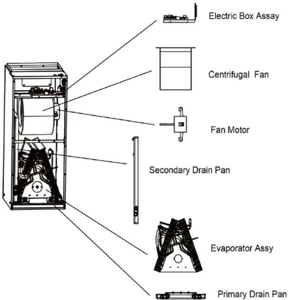
text_image
Electric Box Assay Centrifugal Fan Fan Motor Secondary Drain Pan Evaporator Assy Primary Drain PanFig 2.1
2.2 Rated Working Condition
| Indoor Side Condition | Outdoor Side Condition | |||
| Dry Bulb Temp°C(°F) | Wet Bulb Temp°C(°F) | Dry Bulb Temp°C(°F) | Wet Bulb Temp°C(°F) | |
| Rated Cooling | 27(80.6) | 19(66.2) | 35(95) | 24(75.2) |
| Rated Heating | 20(68.0) | 15(59.0) | 7(44.6) | 6(42.8) |
Indoor Unit Working Temperature Range: 16°C (60.8°F) \~32°C (89.6°F)
3 Preparative for Installation
3.1 Pre-Installation Instruction
3.1.1 Checking Product Received
After receiving the product, please check if there is any damage caused by transportation. Shipping damage is the responsibility of the carrier. Verify the model number, specifications and accessories are correct prior to installation. The distributor or manufacturer will not accept claims from dealers for transportation damage or installation of incorrectly shipped units.
3.1.2 Before Installation
Carefully read all instructions for the installation prior to installing product. Make sure each step or procedure is understood and any special considerations are taken into account before starting installation. Assemble all tools, hardware and supplies needed to complete the installation. Some items may need to be purchased locally. Make sure everything needed to install the product is on hand before starting.
3.1.3 Codes & Regulations
This product is designed and manufactured to comply with national codes. It is installer's responsibilities to install the product in accordance with such codes and/or any prevailing local codes/regulations. The manufacturer assumes no responsibilities for equipment installed in violation of any codes or regulations.
3.1.4 Replacement Parts
When reporting shortages or damages, or ordering repair parts, give the complete product model and serial numbers as stamped on the product. Replacement parts for this product are available through your contractor or local distributor.
3.2 Important Safety Instructions
Recognize Safety Symbols, Words, and Labels
The following symbols and labels are used throughout this manual to indicate immediate or potential hazards. It is the owner's responsibility to read and comply with all safety information and instructions accompanying these symbols. Failure to heed safety information increases the risk of serious personal injury or death, property damage and/or product damage.
DANGER: Immediate hazards which will result in property damage, product damage, severe personal injury or death.
WARNING: Hazards or unsafe practices could result in property damage, product damage, severe personal injury or death.
CAUTION: Hazards or unsafe practices which may result in property damage, product damage, severe personal injury or death.

WARNING: Before serving or installing this equipment. The electrical power to this
unit must be in the “off” position. Caution, more than one disconnect may exist. Failure to observe this warning may result in an electrical shock that can cause personal injury or death.

WARNING: The United States environmental protection agency ('epa') has issued various regulations regarding the introduction and disposal of refrigerants introduced into this unit. Failure to follow these regulations may harm the environment and can lead to the imposition of substantial fines. These regulations may vary due to the passage of laws. A certified technician must perform the installation and service of this product. Should questions arise, contact your local epa office.

WARNING: Due to high system pressure and electrical shock in potential, installation and service work can be dangerous. Only trained and qualified personnels are permitted to install or service this equipment. Observe all warnings contained in this manual and labels/tags attached to the equipment.

WARNING: This product is factory shipped for use with a 208-230/1/60 electrical power supply. This air handler must not be reconfigured to operate with any other power supply.

WARNING: The unit must have an uninterrupted, unbroken electric grounding to minimize the possibility of personal injury if an electric fault occurs. The electric grounding circuit may consist of an appropriate sized power cord which connected with the grounding piece located in the unit control box and also connecting to the building electric service panel. Other methods of grounding are permitted if performed in accordance with the “national electric code” (nec)/ “american national standards institute” (ansi)/ “national fire protection association” (nfpa) 70 and local/state codes. In canada, electric grounding conforms to the canadian electric code csa c22.1. failure to observe this warning can result in electrical shock that can cause personal injury.
text_image
DANGERCARBON MONOXIDE POISONING HAZARD
Special warning for installation of furnaces or air handling units in enclosed areas, such as garages, utility rooms or parking areas.
Carbon monoxide producing devices (such as an automobile, space heater, gas water heater, etc.) should not be operated in enclosed areas such as unventilated garages, utility rooms or parking areas because of the danger of carbon monoxide (CO) poisoning resulting
from the exhaust emissions. If a furnace or air handler is installed in an enclosed area such as a garge, utility room or parking area and a carbon monoxide producing device is operated therein, there must be adequate ventilation directly to outside.
This ventilation is necessary to avoid the danger of CO poisoning which can occur if a carbon monoxide producing device continues to operate in the enclosed area. Carbon monoxide emission can be (re)circulated throughout the building if the furnace or air handler is operating in any mode.
CO can cause serious illness including permanent brain damage or death.
3.3 Requirements for Communication Line
Note:
If the unit is installed in the place with strong electromagnetic interference, shielded wire must be applied on the communication wire between indoor unit and wired controller. Twisted pair line with shielding function must be applied on the communication wire between indoor unit and indoor unit (outdoor unit).
3.3.1 Select communication line for indoor unit and wired controller
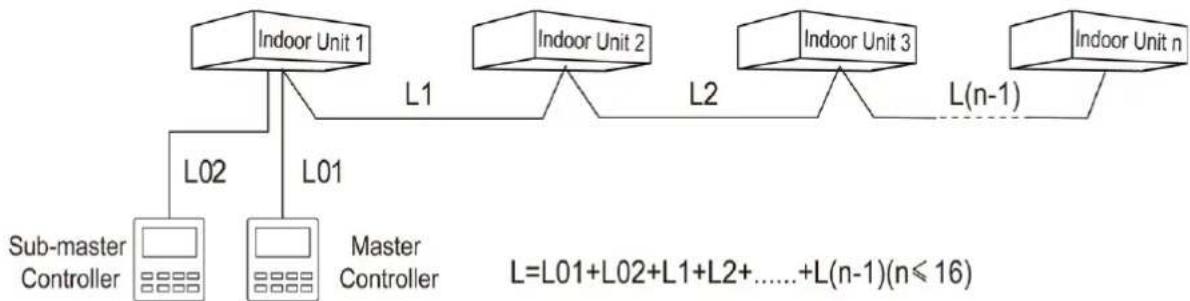
flowchart
graph TD
    A["Indoor Unit 1"] -->|L02| B["Sub-master Controller"]
    A -->|L01| C["Master Controller"]
    D["Indoor Unit 2"] -->|L1| E["L=L01+L02+L1+L2+......+L(n-1)(n≤16)"]
    F["Indoor Unit 3"] -->|L2| G["L(n-1)"]
    F -->|L(n-1)| H["Indoor Unit n"]
Fig 3.3.1
| Wire type | Total length of communication wire between indoor unit and wired controller (m/feet) | Wire diameter (AWG) | Wire standard | Remark |
| Light/Ordinary polyvinyl chloride sheathed cord. (UL60335-2011) | L≤250(850) | 2× 18~2× 16 | UL60335-2011 | 1. Total length of communication cable can't exceed 250m (850feet).2. The cord shall be Circular cord (the cores shall be twisted together).3. If unit is installed in places with intense magnetic field or strong interference, it is necessary to use shielded wire. |
3.3.2 Select communication line for indoor unit and outdoor unit
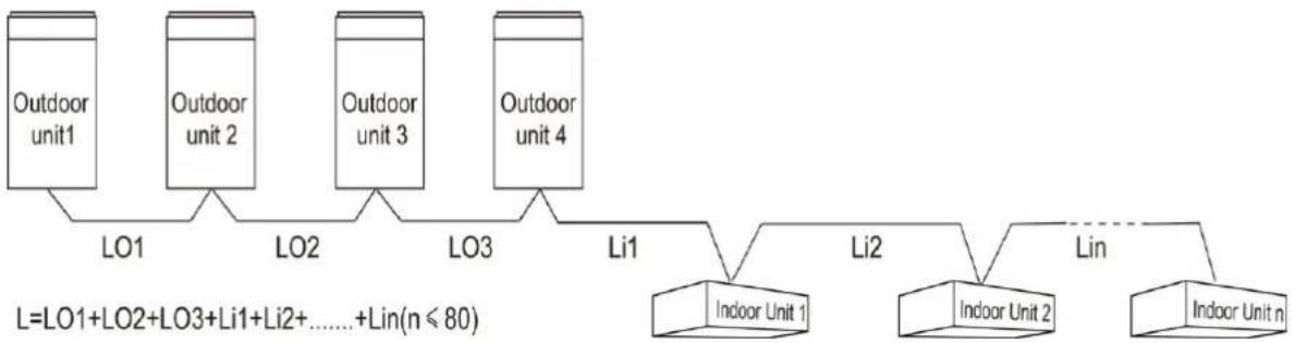
flowchart
graph TD
    A["Outdoor unit1"] --> B["LO1"]
    C["Outdoor unit 2"] --> D["LO2"]
    E["Outdoor unit 3"] --> F["LO3"]
    G["Outdoor unit 4"] --> H["Li1"]
    I["Indoor Unit 1"] --> J["Li2"]
    K["Indoor Unit 2"] --> L["Lin"]
    M["Indoor Unit n"] -.-> L
    note["L=LO1+LO2+LO3+Li1+Li2+......+Lin(n≤80)"]
    note -.-> L
Fig 3.3.2
| Wire type | Total length of communication wire between indoor unit and indoor unit(outdoor unit) (m/feet) | Wire diameter (AWG) | Wire standard | Remark |
| (communication line for indoor unit) Light/Ordinary polyvinyl chloride sheathed cord. (UL60335-2011) | L≤1000(3280) | ≥2×18 | UL60335-2011 | 1. If the wire diameter is enlarged to 18AWG, the total communication cable length can reach 1500m (4920 feet).2. The cord shall be Circular cord (the cores shall be twisted together).3. If unit is installed in places with intense magnetic field or strong interference, it is necessary to use shielded wire. |
| (communication line for outdoor unit) Light/Ordinary polyvinyl chloride sheathed cord. (UL60335-2011) | L≤1000(3280) | ≥2×18 | UL60335-2011 |
3.4 Wiring Requirements
(1) Power Cord Size and Air Switch Capacity
| Model | Power Cord Size | Air Switch apacity (A) | Minimum Sectional Area of Ground Wire(AWG) | Minimum Sectional Area of Power Cord(AWG) |
| GMV-ND09A/A-T(U) | 208/230V-1Ph-60Hz | 15 | 18 | 18 |
| GMV-ND12A/A-T(U) | 15 | 18 | 18 | |
| GMV-ND18A/A-T(U) | 15 | 18 | 18 | |
| GMV-ND24A/A-T(U) | 15 | 18 | 18 | |
| GMV-ND30A/A-T(U) | 15 | 18 | 18 | |
| GMV-ND36A/A-T(U) | 15 | 18 | 18 | |
| GMV-ND42A/A-T(U) | 15 | 18 | 18 | |
| GMV-ND48A/A-T(U) | 15 | 18 | 18 | |
| GMV-ND54A/A-T(U) | 15 | 18 | 18 |
| NOTICE |
| (1) Use copper wire only as unit's power cord. Operating temperature should be within its rated value. |
| (2) If the power cord is more than 15 m (49-1/4 feet) long, please increase properly the sectional area of power cord to avoid overload, which may cause accident. |
| (3) Above selection requirements: Power cord size is based on BV single-core wire (2~4pc) at 40° (104°F)Cambient temperature when laying across plastic pipe. Air switch is D type and used at 40°C (104°F). I actual installation condition varies, please lower the capacity appropriately according to the specifications of power cord and air switch provided by manufacturer. |
| (4) Install cut-off device near the unit. The minimum distance between each stage of cut-off device should be 3 mm (1/8 inch) (The same for both indoor unit and outdoor unit). |
4 Installation Instructions
4.1 Dimension Data
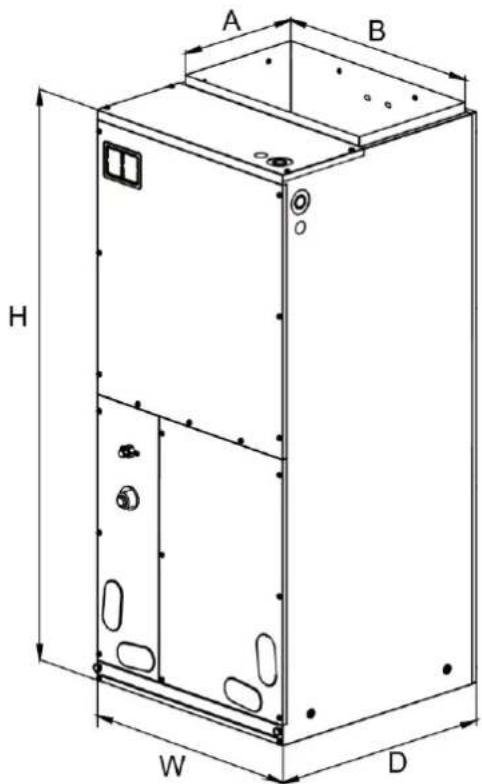
text_image
A B H W DFig 4.1
Unit: Inch (mm)
| MODEL | DIMENSION | ||||
| W | D | H | A | B | |
| GMV-ND09A/A-T(U) | 18-1/8"(460) | 21-1/4"(540) | 43-1/2"(1105) | 11-5/8"(295) | 16-3/4"(426) |
| GMV-ND12A/A-T(U) | 18-1/8"(460) | 21-1/4"(540) | 43-1/2"(1105) | 11-5/8"(295) | 16-3/4"(426) |
| GMV-ND18A/A-T(U) | 18-1/8"(460) | 21-1/4"(540) | 43-1/2"(1105) | 11-5/8"(295) | 16-3/4"(426) |
| GMV-ND24A/A-T(U) | 18-1/8"(460) | 21-1/4"(540) | 43-1/2"(1105) | 11-5/8"(295) | 16-3/4"(426) |
| GMV-ND30A/A-T(U) | 18-1/8"(460) | 21-1/4"(540) | 43-1/2"(1105) | 11-5/8"(295) | 16-3/4"(426) |
| GMV-ND36A/A-T(U) | 21-1/4"(540) | 21-1/4"(540) | 48-1/4"(1224) | 11-5/8"(295) | 20"(508) |
| GMV-ND42A/A-T(U) | 21-1/4"(540) | 21-1/4"(540) | 48-1/4"(1224) | 11-5/8"(295) | 20"(508) |
| GMV-ND48A/A-T(U) | 24-7/8"(630) | 21-1/4"(540) | 48-1/4"(1224) | 11-5/8"(295) | 20"(508) |
| GMV-ND54A/A-T(U) | 24-7/8"(630) | 21-1/4"(540) | 48-1/4"(1224) | 11-5/8"(295) | 20"(508) |
4.2 Location
4.2.1 Installation Site
◆ A place where cool air can be distributed throughout the room.
◆ A place where condensation water is easily drained out.
◆ A place that can bear the weight of indoor unit.
◆ A place which is easy for maintenance.
◆ A place where easy connection with the outdoor unit is available.
◆ A place where is 1m or more away from other electric appliances such as television, audio device, etc.
◆ Avoid a location where there is heat source, high humidity or inflammable gas.
◆ Do not place the unit near a laundry, a bath, a shower or a swimming pool.
◆ Be sure that the installation conforms to the installation dimension diagram.
◆ The space around the unit is adequate for ventilation.
4.2.2 Air Handler

WARNING: This air handler is designed for indoor installation only. Do not install it outdoors.
When installing the air handler, take consideration to minimize the length of refrigerant tubing as much as possible. Do not install the air handler in a location either above or below the condenser that violates the instructions provided with the condenser. Service clearance is to take precedence. Allow a minimum of 24" in front of the unit for service clearance. When installing in an area directly over a finished ceiling (such as an attic), an emergency drain pan is required directly under the unit. See local and state codes for requirements. When installing this unit in an area that may become wet, elevate the unit with a sturdy, non-porous material. In installations that may lead to physical damage (i.e. a garage) it is advised to install a protective barrier to prevent such damage.
This air handler is designed for a complete supply and return ductwork system. Do not operate this product without all ductwork attached.
Based upon the actual conditions, if air handler is installed as Fig 4.2(A), the air handler should be concealed in a specific room or space and make sure the air handler is not accessible to the general public.
Based upon the actual conditions, if air handler is installed as Fig 4.2(B), make sure that there is enough space for care and maintenance and the height between the air handler and ground is above 2500mm. And the air handler is not accessible to the general public.
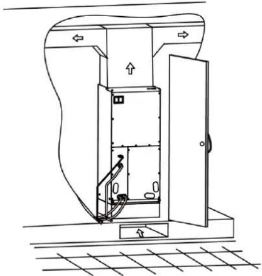
natural_image
Technical line drawing of an open electrical cabinet with internal components and directional arrows (no text or symbols)(A)
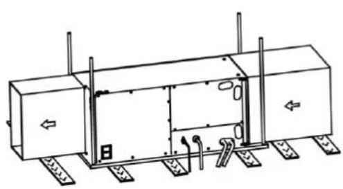
natural_image
Technical line drawing of a mechanical or electrical enclosure with mounting base and side panels (no text or symbols)(B)
Fig 4.2
4.3 Piping Work
4.3.1 Specification of Connection Pipe
| Model | External Diameter (inch) | |
| Gas Pipe(in) | Liquid Pipe(in) | |
| GMV-ND09A/A-T(U) | 3/8 | 1/4 |
| GMV-ND12A/A-T(U) | 1/2 | 1/4 |
| GMV-ND18A/A-T(U) | 5/8 | 3/8 |
| GMV-ND24A/A-T(U) | 5/8 | 3/8 |
| GMV-ND30A/A-T(U) | 5/8 | 3/8 |
| GMV-ND36A/A-T(U) | 5/8 | 3/8 |
| GMV-ND42A/A-T(U) | 5/8 | 3/8 |
| GMV-ND48A/A-T(U) | 5/8 | 3/8 |
| GMV-ND54A/A-T(U) | 5/8 | 3/8 |
4.3.2 Piping Preparation
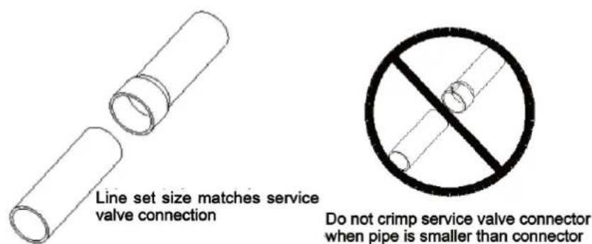
All cut ends are to be round, burr free, and cleaned. Failure to follow this practice increases the chances for refrigerant leakage.
text_image
Line set size matches service valve connection Do not crimp service valve connector when pipe is smaller than connectorFig 4.3
4.4 Condensate Removal
(1) It is not allowed to connect the condensate drain pipe into waste pipe or other pipelines which are likely to produce corrosive or peculiar smell to prevent the smell from entering indoors or corrupt the unit.
(2) It is not allowed to connect the condensate drain pipe into rain pipe to prevent rain water from pouring in and cause property loss or personal injury.
(3) Condensate drain pipe should be connected into special drain system for air conditioner.
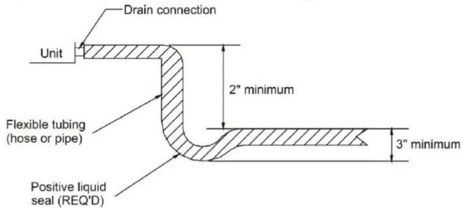
(4) The drain pan has primary and secondary drain connection (Figure 4.4). Condensate removal is performed by attaching a 3/4" PVC pipe to the evaporator coil pan and terminated in accordance with local or state Plumbing/HVAC codes. The installation must include a "P" style trap that is located closely to the evaporator coil. Do not over-tighten the drain connection(s) in order to prevent possible damage to the evaporator drain pan. See Fig 4.4 for details of a typical condensate line "P" trap.
text_image
Drain connection Unit 2" minimum Flexible tubing (hose or pipe) 3" minimum Positive liquid seal (REQ'D)Fig 4.4
4.5 Ductwork
This air handler is designed for a complete supply and return ductwork system.

WARNING: Do not operate the unit without all ductwork completed.
Do not operate this product without all ductwork attached.
Inadequate ductwork that restricts airflow can result in improper performance and compressor or heater failure. Ductwork is to be constructed in a manner that limits restrictions and maintains suitable air velocity. Ductwork is to be sealed to the unit in a manner that will prevent leakage.
Return Ductwork: Do not terminate the return ductwork in an area that can introduce toxic, or objectionable fumes/odors into the ductwork. The return ductwork is to be introduced into the air handler bottom (upflow configuration).
Return Air Filters: Each installation must include a return air filter. This filtering may be performed at the air handler or externally such as a return air filter grille.
4.6 Installation of Wired Controller
Please refer to User Manual of Wired Controller for the installation details.

Note: When installation is finished, the unit must be tested and debugged before
operation. Please refer to Instruction Manual of ODU for auto addressing and debugging details.
5 Wiring Work

WARNING
Before obtaining access to terminals, all supply circuits must be disconnected.
| NOTICE |
| (1) Units must be earthed securely, or it may cause electric shock. |
| (2) Please carefully read the wiring diagram before carry out the wiring work, incorrect wiring could cause malfunction or even damage the unit. |
| (3) The unit should be powered by independent circuit and specific socket. |
| (4) The wiring should be in accordance with related regulations in order to ensure the units reliable running. |
| (5) Install circuit breaker for branch circuit according to related regulations and electrical standards. |
| (6) Keep cable away from refrigerant pipings, compressor and fan motor. |
| (7) The communication wires should be separated from power cord and connection wire between indoor unit and outdoor unit. |
| (8) Adjust the static pressure via wired controller according to site circumstance. |
| (9) If the supply cord is damaged, it must be replaced by manufacturer, its service agent or similarly qualified persons in order to avoid a hazard. |
5.1 Connection of Wire and Patch Board Terminal
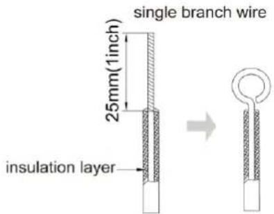
(1) The connection of wire (as shown in fig 5.1.1)
1) Strip about 25mm (1 inch) insulation of the wire end by stripping and cutting tool.
2) Remove the wiring screws on the terminal board.
3) Shape the tail of wire into ring by needle nose plier, and keep the gauge of ring in accordance with screw.
4) Use the screwdriver for tightening the terminal.
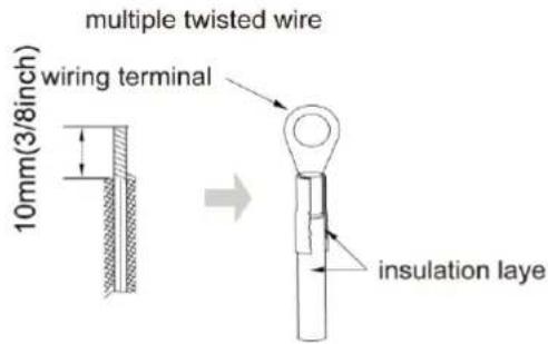
(2) The connection of stranded wire (as shown in fig 5.1.2)
1) Strip about 10mm (3/8 inch) insulation of the end of stranded wire by stripping and cutting tool.
2) Loosen the wiring screws on terminal board.
3) Insert the wire into the ring tongue terminal and tighten by crimping tool.
4) Use the screwdriver for tightening the terminal.
text_image
single branch wire 25mm(1inch) insulation layerFig 5.1.1
text_image
multiple twisted wire wiring terminal 10mm(3/8inch) insulation layeFig 5.1.2
5.2 Power Cord Connection
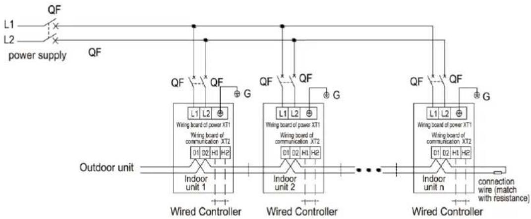
NOTICE! All indoor units must be unified of power supply so that they can be powered ON/OFF at the same time.
flowchart
graph TD
    A["Power Supply L1"] --> B["QF"]
    C["Outdoor unit"] --> D["Wired Controller"]
    E["Connection Wire (match with resistance)"] --> F["Wired Controller"]
    G["Indoor unit n"] --> H["Wired Controller"]
    I["Wiring Board of Power XT1"] --> J["Wired Controller"]
    K["Wiring Board of Communication XT2"] --> L["Wired Controller"]
    M["Indoor unit 1"] --> N["Wired Controller"]
    O["Indoor unit 2"] --> P["Wired Controller"]
    Q["Indoor unit n"] --> R["Wired Controller"]
    S["QF"] --> T["QF"]
    U["QF"] --> V["QF"]
    W["QF"] --> X["QF"]
    Y["QF"] --> Z["QF"]
    AA["QF"] --> AB["QF"]
    AC["QF"] --> AD["QF"]
    AE["QF"] --> AF["QF"]
    AG["G"] --> AH["G"]
    AI["G"] --> AJ["G"]
Note: indoor unit quantity n is according to the outdoor unit capacity.
Fig 5.2
- For units with single-phase power supply.
(1) Detach the electric box lid.
(2) Let the power cord pass through the wiring through-holes.
(3) Connect the power cord to terminal "L, N, ☑".
(4) Fix the power cord with wiring clamp.
5.3 Connection of Communication Wire between Indoor Unit and Outdoor Unit (or indoor unit)
(1) Detach the electric box lid.
(2) Let the Communication cable pass through the wiring through-holes.
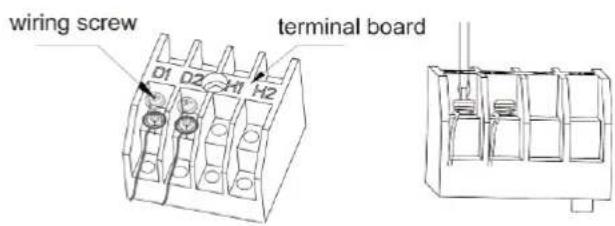
(3) Connect the communication wire to terminal D1 and D2 of indoor 4-bit wiring board, as shown in fig 5.3.1.
text_image
wiring screw 01 02 H1 H2 terminal boardFig 5.3.1
flowchart
graph TD
    A[" indoor unit "] --> B[" IDU PCB "]
    B --> C[" communication interface CN12 "]
    C --> D[" previous IDU "]
    D --> E[" match resistance for communication "]
    style A fill:#f9f,stroke:#333
    style B fill:#ccf,stroke:#333
    style C fill:#cfc,stroke:#333
    style D fill:#fcc,stroke:#333
    style E fill:#cff,stroke:#333
Fig 5.3.2
(4) Fix the communication cable with clamp of electric box.
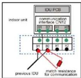
(5) For more reliable communication, make sure connect the terminal resistor to the most downstream IDU of the communication bus (terminal D1 and D2), as shown in fig 5.3.2, terminal resistor is provided with each ODU.
5.4 Connect Communication Wire of Wired Controller
(1) Open electric box cover of indoor unit.
(2) Let the communication wire go through the rubber ring.
(3) Connect the communication wire to terminal H1 and H2 of indoor 4-bit wiring board.
(4) Fix the communication wire with wire clip on the electric box.
(5) Wiring instructions of remote receiving light board and wired controller:
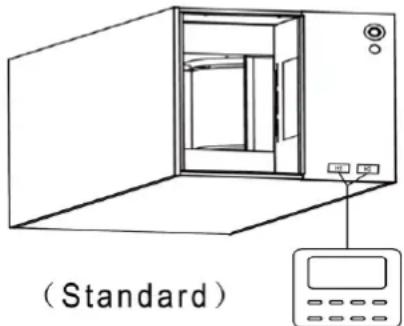
1) Fig 5.4.1 shows the installation of wired controller.
natural_image
Line drawing of a standard open refrigerator with control panel and indicator lights (no text or symbols on the device itself)Fig 5.4.1
2) Wired controller and receiving light board can be installed at the same time. When operating through a remote controller, both wired controller and the receiving light board can receive the signals.
5.5 Illuminate for Connection of Wired Controller and Indoor Units Network
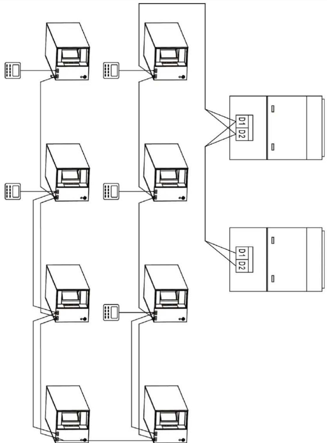
(1) Communication wire of indoor unit and outdoor unit (or indoor unit) is connected to D1, D2.
(2) Wired controller is connected to H1, H2.
(3) One indoor unit can connect two wired controllers that must be set as master one and slave one.
(4) One wired controller can control 16 indoor unitS in maximum at the same time (As shown in fig5.5).
| NOTICE |
| (1) The type of indoor units must be the same if they are controlled by the same wired controller. |
| (2) When the indoor unit is controlled by two wired controllers, the addresses of the two wired controllers should be different through address setting. Address 1 is for main controller; Address 2 is for slave controller. Detailed setting please refer to the instruction manual of wired controller. |
flowchart
graph TD
    A["Computer 1"] --> B["Server D1"]
    C["Computer 2"] --> B
    D["Computer 3"] --> B
    E["Computer 4"] --> B
    F["Computer 5"] --> B
    G["Computer 6"] --> B
    H["Computer 7"] --> B
    I["Computer 8"] --> B
    J["Computer 9"] --> B
    K["Computer 10"] --> B
    L["Computer 11"] --> B
    M["Computer 12"] --> B
    N["Computer 13"] --> B
    O["Computer 14"] --> B
    P["Computer 15"] --> B
    Q["Computer 16"] --> B
    R["Computer 17"] --> B
    S["Computer 18"] --> B
    T["Computer 19"] --> B
    U["Computer 20"] --> B
    V["Computer 21"] --> B
    W["Computer 22"] --> B
    X["Computer 23"] --> B
    Y["Computer 24"] --> B
    Z["Computer 25"] --> B
    AA["Computer 26"] --> B
    AB["Computer 27"] --> B
    AC["Computer 28"] --> B
    AD["Computer 29"] --> B
    AE["Computer 30"] --> B
    AF["Computer 31"] --> B
    AG["Computer 32"] --> B
    AH["Computer 33"] --> B
    AI["Computer 34"] --> B
    AJ["Computer 35"] --> B
    AK["Computer 36"] --> B
    AL["Computer 37"] --> B
    AM["Computer 38"] --> B
    AN["Computer 39"] --> B
    AO["Computer 40"] --> B
    AP["Computer 41"] --> B
    AQ["Computer 42"] --> B
    AR["Computer 43"] --> B
    AS["Computer 44"] --> B
    AT["Computer 45"] --> B
    AU["Computer 46"] --> B
    AV["Computer 47"] --> B
    AW["Computer 48"] --> B
    AX["Computer 49"] --> B
    AY["Computer 50"] --> B
Fig 5.5
6 Routine Maintenance
| NOTICE |
| (1) Do turn off the unit and cut off the main power supply when cleaning the air conditioner to avoid electric shock or injury. |
| (2) Stand at solid table when cleaning the unit. |
| (3) Do not clean the unit with hot water whose temperature is higher than 45°C to prevent fade or deformation. |
| (4) Do not dry the filters by fire, or it may catch fire or become deformed. |
| (5) Clean the filter with a wet cloth dipped in neutral detergent. |
| (6) Please contact after-sales service staff if there is abnormal situation. |
6.1 Cleaning of Filter
(1) Remove the filters from inlet of IDU. Use a vacuum cleaner to remove dust. If the filters are dirty, wash them with warm water and mild detergent, and dry the filters in the shade.
(2) If the unit used in the environment with much dust, please clean it regularly. (Usually once every two weeks).
6.2 Maintenance before the Seasonal Use
(1) Check if the air inlet and air outlet of indoor and outdoor unit are blocked.
(2) Check if securely grounded.
(3) Check if all the power cord and communication cable are securely connected.
(4) Check if any error code displayed after energized.
6.3 Maintenance after the Seasonal Use
(1) Set the unit in fan mode for half a day in a sunny day to dry the inner part of unit;
(2) When the unit won't be used for a long time, please cut off power supply for energy saving; the characters on the wired controller screen will disappear after cutting off the power supply.
7 Table of Error Codes for Indoor Unit
| Error Code | Content | Error Code | Content | Error Code | Content |
| L0 | Indoor Unit Error | L9 | Quantity Of Group Control Indoor Units Setting Error | d8 | Water Temperature Sensor Error |
| L1 | Indoor Fan Protection | LA | Indoor Units Incompatibility Error | d9 | Jumper Cap Error |
| L2 | E-heater Protection | LH | Low Air Quantity Warning | dA | Indoor Unit Hardware Address Error |
| L3 | Water Full Protection | LC | Outdoor-Indoor Incompatibility Error | dH | Wired Controller PC-Board Error |
| L4 | Wired Controller Power Supply Error | d1 | Indoor Unit PC-Board Error | dC | Capacity DIP Switch Setting Error. |
| L5 | Anti-Frosting Protection | d3 | Ambient Temperature Sensor Error | dL | Outlet Air Temperature Sensor Error |
| L7 | No Master Indoor Unit Error | d4 | Inlet Pipe Temperature Sensor Error | dE | Indoor Unit CO2 Sensor Error |
| L8 | Power Insufficiency Protection | d6 | Outlet Pipe Temperature Sensor Error | db | Special Code: Field Debugging Code |
8 Troubleshooting
The air conditioner is not expected to be serviced by users. Incorrect repair may cause electric shock or fire, so please contact an authorized service center for professional service. The following checks prior to contact may save your time and money.
| Phenomenon | Troubleshooting |
| The unit can’t start | 1 Power supply is not connected.2 Circuit breaker tripping caused by leakage of electricity.3 Input voltage is too low.4 Defect of main PC-board. |
| The unit stops after running for a while. | 1 The inlet or outlet of ODU or IDU are blocked by obstacle. |
| Poor cooling effect | 1 The filter is dirty.2 Too heavy heat load of room (e.g. too many people)3 Door or windows is open.4 Inlet and outlet of IDU are blocked.5 Setting temperature is too high.6 Refrigerant is insufficient (e.g. refrigerant leakage) |
| Poor heating effect | 1 The filter is dirty.2 Door or window is open.3 Setting temperature is too low.4 Refrigerant is insufficient (e.g. refrigerant leakage) |
| Indoor fan doesn’t start up during heating | 1 At starting, the IDU fan could not operate till the heat exchange become hot, for preventing delivering the cool air.2 At defrosting, the IDU fan stopped due to system switch to cooling mode. For preventing delivering the cool air, and resume operating after defrosting. |
Note:
If air conditioner still fails to work normally after checking and handling as described above, please stop using it immediately and contact local service center for assistance.
natural_image
Architectural structure with curved roof and window patterns, no visible text or symbols
GREE
GREE ELECTRIC APPLIANCES, INC. OF ZHUHAI
Add: West Jinji Rd, Qianshan, Zhuhai, Guangdong, China, 519070
Tel: (+86-756) 8522218
Fax: (+86-756) 8669426
E-mail: gree@gree.com.cn www.gree.com
600005000185