
GMV-ND09ZD/A-T(U) - Air-conditioner GREE - Free user manual and instructions
Find the device manual for free GMV-ND09ZD/A-T(U) GREE in PDF.


User questions about GMV-ND09ZD/A-T(U) GREE
0 question about this device. Answer the ones you know or ask your own.
Ask a new question about this device
Download the instructions for your Air-conditioner in PDF format for free! Find your manual GMV-ND09ZD/A-T(U) - GREE and take your electronic device back in hand. On this page are published all the documents necessary for the use of your device. GMV-ND09ZD/A-T(U) by GREE.
USER MANUAL GMV-ND09ZD/A-T(U) GREE
Original Instructions
AHU-KIT
Models:
GMV-N12U/A-T(U)
GMV-N24U/A-T(U)
GMV-N48U/A-T(U)
GMV-N96U/A-T(U)
GMV-N192U/A-T(U)
Thank you for choosing commercial air conditioners. Please read this Owner's Manual carefully before operation and retain it for future reference.
If you have lost the Owner's Manual, please contact the local agent or visit www.gree.com or send an email to global@gree.com.cn for the electronic version.
GREE ELECTRIC APPLIANCES, INC. OF ZHUHAI
Preface
For correct installation and operation, please read all instructions carefully. Before reading the instructions, please be aware of the following items:
 | This is the safety alert symbol. It is used to alert you to potential personal injury hazards. Obey all safety messages that follow this symbol to avoid possible injury or death. | |
 | This mark indicates procedures which, if improperly performed, might lead to the death or serious injury of the user. | |
 | This mark indicates procedures which, if improperly performed, might possibly result in personal harm to the user, or damage to property. | |
 | NOTICE is used to address practices not related to personal injury. | |
WARNING
| (1) Instructions for installation and use of this product are provided by the manufacturer. |
| (2) Installation must be performed in accordance with the requirements of NEC and CEC by authorized personnel only. |
| (3) For the safe operation of this unit, please read and follow the instructions carefully. |
| (4) During operation, total capacity of indoor units should not exceed the total capacity of outdoor units. otherwise, poor effect of cooling or heating may result. |
| (5) Direct operators or maintainers should well keep this manual. |
| (6) If this unit fails to operate normally, please contact our service center as soon as possible and provide the following information:1) Content on the nameplate (model number, cooling capacity, production code, ex-factory date.2) Malfunction details (before and after the malfunction occurs). |
| (7) Each unit has been strictly tested and proved to be qualified before ex-factory. In order to prevent units from being damaged or operating normally because of improper disassembly, please do not disassemble the unit by yourself. If you need to disassemble and check units, please contact our service center. We will send specialists to guide the disassembly. |
| (8) Installation must be performed in accordance with the requirements of NEC and CEC by authorized personnel only. |
This appliance can be used by children aged from 8 years and above and persons with reduced physical, sensory or mental capabilities or lack of experience and knowledge if they have been given supervision or instruction concerning use of the appliance in a safe way and understand the hazards involved. Children shall not play with the appliance. Cleaning and user maintenance shall not be made by children without supervision.
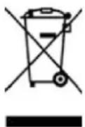
DISPOSAL: Do not dispose this product as unsorted municipal waste. Collection of such waste separately for special treatment is necessary.
| Exception Clauses |
| Manufacturer will bear no responsibilities when personal injury or property loss is caused by the following reasons: |
| (1) Damage the product due to improper use or misuse of the product; |
| (2) Alter, change, maintain or use the product with other equipment without abiding by the instructic manual of manufacturer; |
| (3) After verification, the defect of product is directly caused by corrosive gas; |
| (4) After verification, defects are due to improper operation during transportation of product; |
| (5) Operate, repair, maintain the unit without abiding by instruction manual or related regulations; |
| (6) After verification, the problem or dispute is caused by the quality specification or performance of parts and components that produced by other manufacturers; |
| (7) The damage is caused by natural calamities, bad using environment or force majeure. |
Contents
1 Safety Precautions....1
2 Product Introduction.... 2
2.1 Names of Key Components 2
2.2 Overall System Connection Diagram 2
2.3 Standard Fittings....3
2.4 Specifications.... 4
2.5 Selecting the Air Handling Unit 5
3 Preparations for Installation 9
3.1 Before Installation 9
3.2 Location for Installation 10
3.3 Requirements for Communication Wire 11
3.4 Wiring Requirements 13
3.5 Piping Requirements ...... 13
3.6 Capacity Setting....16
4 Installation Instructions....17
4.1 Unit Dimensions and Maintenance Space.... 17
4.2 EXV Installation 20
4.3 Installation of the EXV Cable 22
4.4 Piping Installation.... 22
4.5 Installation of the Control Box 23
4.6 Installation of the Temperature sensors 26
4.7 Installation of Wired Controller 29
5 Wire Connection .... 30
5.1 Connect Cables and Terminals of Wiring Board 30
5.2 Power Cord Connection.... 31
5.3 Connection of Communication Wire between Indoor Unit and Outdoor Unit (or Indoor Unit) 32
5.4 Connect Communication Wire of Wired Controller 33
5.5 Illuminate for Connection of Wired Controller and Indoor Units (AHU-KIT) Network 33
6 Statement on linkage function setting.... 35
7 Operation and Maintenance 36
7.1 Before Operation.... 36
7.2 Test Operation 36
7.3 Routine Maintenance.... 36
7.4 Disposal Requirements.... 37
8 Table of Error Codes for Indoor Unit 37
9 Troubleshooting.... 38
1 Safety Precautions
| ▲WARNING |
| (1) This product can't be installed at corrosive, inflammable or explosive environment or the place with special requirements, such as kitchen. Otherwise, it will affect the normal operation or shorten the service life of the unit, or even cause fire hazard or serious injury. As for above special places, please adopt special air conditioner with anti-corrosive or anti-explosion function. |
| (2) Follow this instruction to complete the installation work. Please carefully read this manual before unit startup and service. |
| (3) Wire size of power cord should be large enough. The damaged power cord and connection wire should be replaced by exclusive cable. |
| (4) After connecting the power cord, please fix the electric box cover properly in order to avoid accident. |
| (5) Never fail to comply with the nitrogen charge requirements. Charge nitrogen when welding pipes. |
| (6) Never short-circiut or cancel the pressure switch to prevent unit damage. |
| (7) Please firstly connect the wired controller before energization, otherwise wired controller can not be used. |
| (8) Before using the unit, please check if the piping and wiring are correct to avoid water leakage, refrigerant leakage, electric shock, or fire etc.. |
| (9) Do not insert fingers or objects into air outlet/inlet grille. |
| (10) Open the door and window and keep good ventilation in the room to avoid oxygen deficit when the gas/oil supplied heating equipment is used. |
| (11) Never start up or shut off the air conditioner by means of directly plug or unplug the power cord. |
| (12) Turn off the unit after it runs at least five minutes; otherwise it will influence oil return of the compressor. |
| (13) Do not allow children operate this unit. |
| (14) Do not operate this unit with wet hands. |
| (15) Turn off the unit or cut off the power supply before cleaning the unit, otherwise electric shock or injury may happen. |
| (16) Never spray or flush water towards unit, otherwise malfunction or electric shock may happen. |
| (17) Do not expose the unit to the moist or corrosive circumstances. |
| (18) Under cooling mode, please don't set the room temperature too low and keep the temperature difference between indoor and outdoor unit within 5°C(41°F). |
| (19) User is not allowed to repair the unit. Fault service may cause electric shock or fire accidents. Please contact Gree appointed service center for help. |
| (20) Before installation, please check if the power supply is in accordance with the requirements specified on the nameplate. And also take care of the power safety. |
| (21) Installation should be conducted by dealer or qualified personnel. Please do not attempt to install the unit by yourself. Improper handling may result in water leakage, electric shock or fire disaster etc.. |
| (22) The control box should be installed inside |
| (23) Be sure to use the exclusive accessory and part to prevent the water leakage, electric shock and fire accidents. |
| (24) Make sure the unit can be earthed properly and soundly after plugging into the socket so as to avoid electric shock. Please do not connect the ground wire to gas pipe, water pipe, lightning rod or telephone line. |
| (25) Electrify the unit 8 hours before operation. Please switch on for 8 hours before operation. Do not cut off the power when 24 hours short-time halting (to protect the compressor). |
| (26) If refrigerant leakage happens during installation, please ventilate immediately. Poisonous gas will emerge if the refrigerant gas meets fire. |
| (27) Volatile liquid, such as diluent or gas will damage the unit appearance. Only use soft cloth with a little neutral detergent to clean the outer casing of unit. |
| (28) If anything abnormal happens (such as burning smell), please power off the unit and cut off the main power supply, and then immediately contact Gree appointed service center. If abnormality keeps going, the unit might be damaged and lead to electric shock or fire. |
Any personal injury or property loss caused by improper installation, improper debug, unnecessary repair or not following the instructions of this manual should not be the responsibility of Gree Electric Appliances, Inc. of Zhuhai.
2 Product Introduction
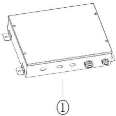
2.1 Names of Key Components
natural_image
Line drawing of a rectangular electronic device with mounting holes and labeled part (1), no text or symbols present.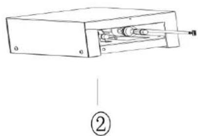
natural_image
Diagram of a device with internal components and labeled parts (no text or symbols)Fig.2.1
| No. | 1 | 2 |
| Name | Control Box | EXV Box |
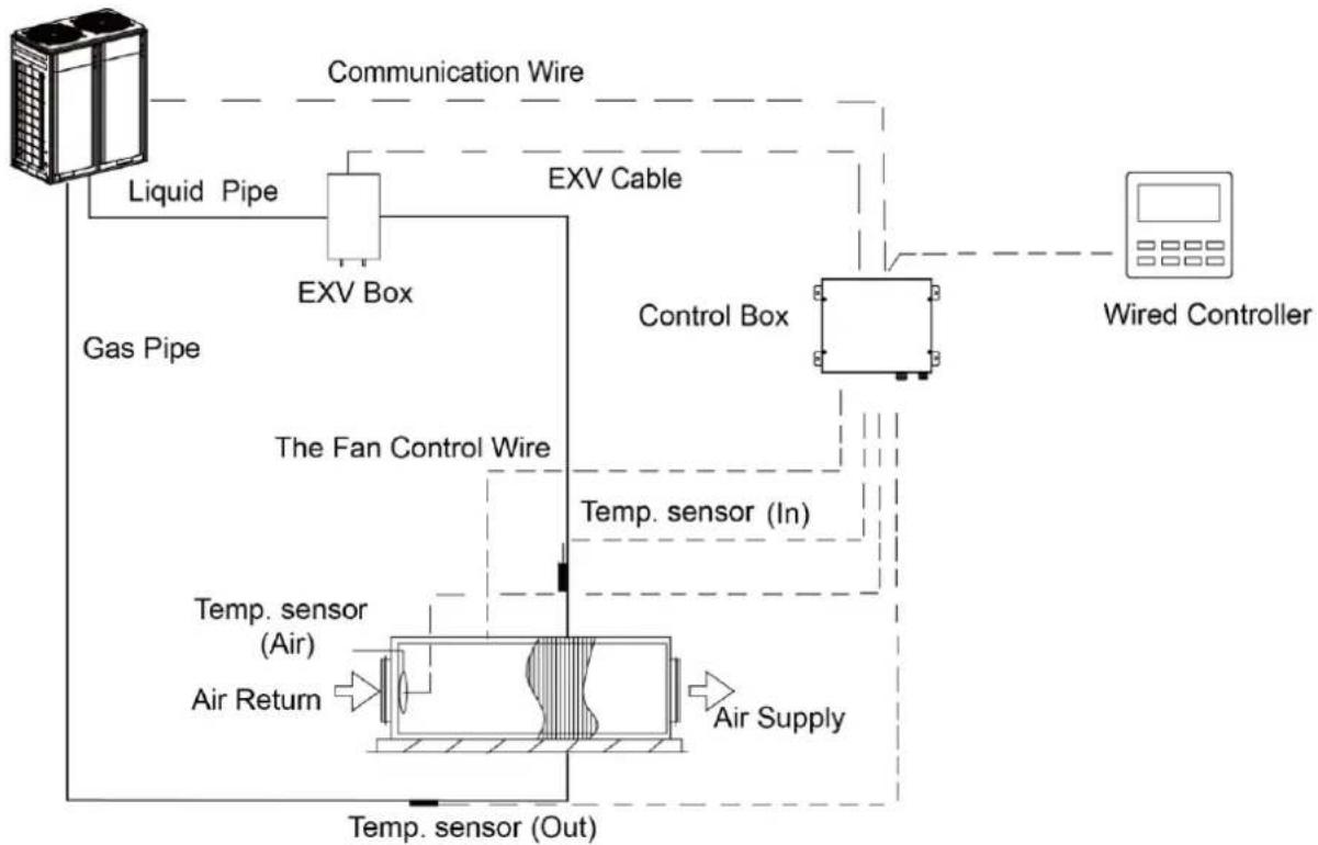
2.2 Overall System Connection Diagram
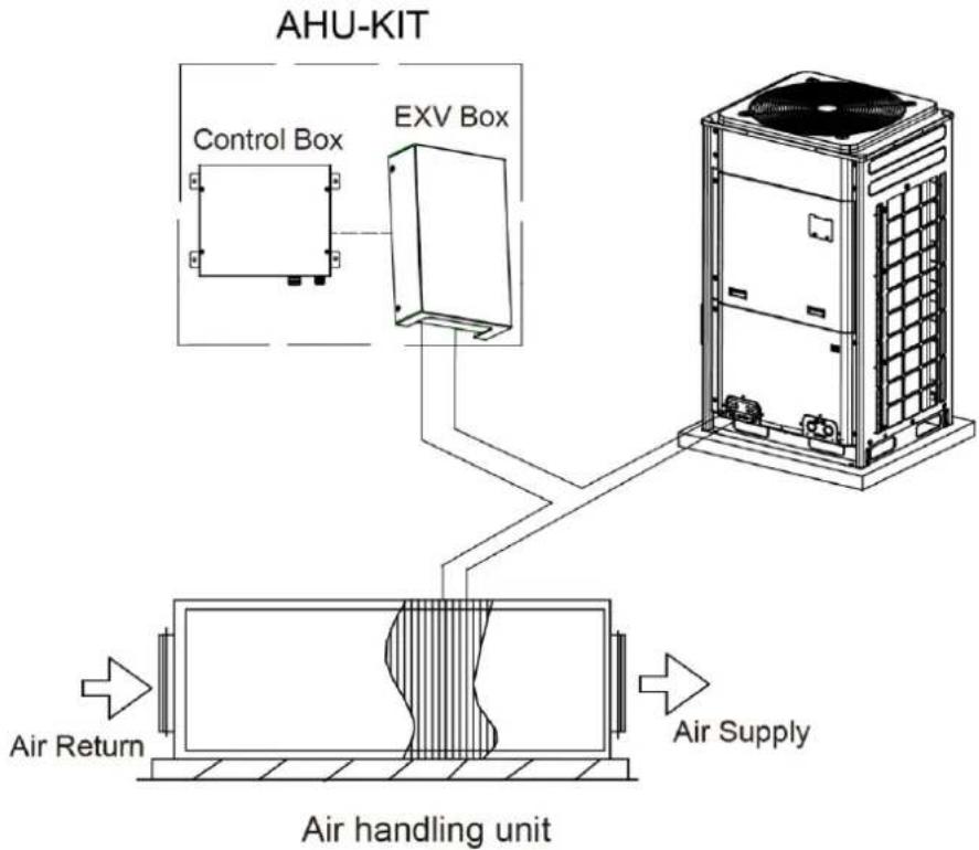
When one AHU-KIT is connected to one AHU, the connection diagram is as follows:
flowchart
graph TD
    A["Gas Pipe"] -->|Liquid Pipe| B["EXV Box"]
    B --> C["EXV Cable"]
    C --> D["Control Box"]
    D --> E["Wired Controller"]
    E --> F["Air Supply"]
    F --> G["Temp. sensor (Out)"]
    G --> H["Temp. sensor (Air)"]
    H --> I["The Fan Control Wire"]
    I --> J["Temp. sensor (In)"]
    J --> K["Communication Wire"]
Fig.2.2.1
When several AHU-KITs (n≤2) are in parallel connection with one AHU, the connection diagram is as follows:
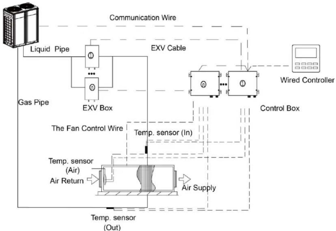
flowchart
graph TD
    A["Liquid Pipe"] --> B["ExV Box"]
    C["Gas Pipe"] --> B
    B --> D["EXV Cable"]
    D --> E["Wired Controller"]
    E --> F["Control Box"]
    F --> G["Temp. sensor (In)"]
    G --> H["Temp. sensor (Air)"]
    H --> I["Air Return"]
    I --> J["Temp. sensor (Out)"]
    J --> K["Air Supply"]
    K --> L["The Fan Control Wire"]
    L --> M["Communication Wire"]
Fig.2.2.2
2.3 Standard Fittings
Please use the supplied standard fittings listed below as instructed.
| No. | Name | Appearance | Quantity |
| 1 | Magnetic ring | 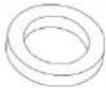 | 1 or 2 |
| 2 | Swell screw | 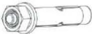 | 4 |
| 3 | Self-tapping screw | 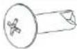 | 4 |
| 4 | Operating Instruction Manual |  | 1 |
| 5 | Wired controller |  | 1 |
| 6 | Insulator |  | 2 |
| 7 | aluminum tape |  | 2 |
| 8 | rubber belt |  | 2 |
| 9 | Fastener |  | 4 |
2.4 Specifications
| Model | GMV-N12U/A-T(U) | GMV-N24U/A-T(U) | GMV-N48U/A-T(U) | ||||||||
| Defaulted capacity of ex-factory | Capacity | 12 | 24 | 48 | |||||||
| Cooling | kW | 3.52 | 7.03 | 14.07 | |||||||
| Cooling | kBtu/h | 12.0 | 24.0 | 48.0 | |||||||
| Heating | kW | 3.96 | 7.91 | 15.83 | |||||||
| Heating | kBtu/h | 13.5 | 27.0 | 54.0 | |||||||
| Adjustable capacity | Capacity | 9 | 12 | 15 | 18 | 24 | 30 | 36 | 48 | ||
| Cooling | kW | 2.64 | 3.52 | 4.40 | 5.28 | 7.03 | 8.79 | 10.55 | 14.07 | ||
| Cooling | kBtu/h | 9.5 | 12.0 | 15.0 | 18.0 | 24.0 | 30.0 | 36.0 | 48.0 | ||
| Heating | kW | 3.08 | 3.96 | 4.98 | 5.86 | 7.91 | 9.96 | 11.72 | 15.83 | ||
| Heating | kBtu/h | 10.5 | 13.5 | 17.0 | 20.0 | 27.0 | 34.0 | 40.0 | 54.0 | ||
| Power input | W | 5.0 | 5.0 | 5.0 | |||||||
| Power Supply | Ph /V /Hz | 1-Ph 208/230V 60Hz | 1-Ph 208/230V 60Hz | 1-Ph 208/230V 60Hz | |||||||
| Size of connection pipe | AHU-KIT (ex-factory pipe size) | mm | Φ6.35 | Φ6.35 | Φ9.52 | Φ9.52 | Φ9.52 | Φ9.52 | Φ9.52 | Φ9.52 | |
| in. | 1/4 | 1/4 | 3/8 | 3/8 | 3/8 | 3/8 | 3/8 | 3/8 | |||
| Air handling unit | Liquid pipe | mm | Φ6.35 | Φ6.35 | Φ6.35 | Φ9.52 | Φ9.52 | Φ9.52 | Φ9.52 | Φ9.52 | |
| in. | 1/4 | 1/4 | 1/4 | 3/8 | 3/8 | 3/8 | 3/8 | 3/8 | |||
| Gas pipe | mm | Φ9.52 | Φ12.7 | Φ12.7 | Φ15.9 | Φ15.9 | Φ15.9 | Φ15.9 | Φ15.9 | ||
| in. | 3/8 | 1/2 | 1/2 | 5/8 | 5/8 | 5/8 | 5/8 | 5/8 | |||
| Connection method | Brazing Connection | Brazing Connection | Brazing Connection | ||||||||
| Outline dimension (W×D×H) | EXV box | mm | 203×326×85 | 203×326×85 | 203×326×85 | ||||||
| in. | 8×12-7/8×3-3/8 | 8×12-7/8×3-3/8 | 8×12-7/8×3-3/8 | ||||||||
| Control box | mm | 334×284×111 | 334×284×111 | 334×284×111 | |||||||
| in. | 13-1/8×11-1/8×4-3/8 | 13-1/8×11-1/8×4-3/8 | 13-1/8×11-1/8×4-3/8 | ||||||||
| Net weight | kg | 9.5 | 9.5 | 9.5 | |||||||
| Ibs | 21 | 21 | 21 | ||||||||
| Model | GMV-N96U/A-T(U) | GMV-N192U/A-T(U) | |||||||
| Defaulted capacity of ex-factory | Capacity | 96 | 192 | ||||||
| Cooling | kW | 28.14 | 56.27 | ||||||
| Cooling | kBtu/h | 96.0 | 192 | ||||||
| Heating | kW | 31.65 | 63.31 | ||||||
| Heating | kBtu/h | 108.0 | 216 | ||||||
| Adjustable capacity | Capacity | 72 | 96 | 120 | 144 | 168 | 192 | 288 | |
| Cooling | kW | 21.10 | 28.14 | 35.17 | 42.20 | 49.24 | 56.27 | 84.41 | |
| Cooling | kBtu/h | 72 | 96 | 120 | 144 | 168 | 192 | 288 | |
| Heating | kW | 23.74 | 31.65 | 39.57 | 47.48 | 55.39 | 63.31 | 94.96 | |
| Heating | kBtu/h | 81 | 108 | 135 | 162 | 189 | 216 | 324 | |
| Power input | W | 5.0 | 5.0 | ||||||
| Power Supply | Ph /V/ Hz | 1-Ph 208/230V 60Hz | 1-Ph 208/230V 60Hz | ||||||
| Model | GMV-N96U/A-T(U) | GMV-N192U/A-T(U) | ||||||||
| Size of connection pipe | AHU-KIT (ex-factory pipe size) | mm | Φ9.52 | Φ9.52 | Φ9.52 | Φ9.52 | Φ15.9 | Φ15.9 | Φ15.9 | |
| in. | 3/8 | 3/8 | 3/8 | 3/8 | 5/8 | 5/8 | 5/8 | |||
| Air handling unit | Liquid pipe | mm | Φ9.52 | Φ9.52 | Φ12.7 | Φ12.7 | Φ15.9 | Φ15.9 | Φ19.05 | |
| in. | 3/8 | 3/8 | 1/2 | 1/2 | 5/8 | 5/8 | 3/4 | |||
| Gas pipe | mm | Φ19.05 | Φ22.2 | Φ28.6 | Φ28.6 | Φ28.6 | Φ28.6 | Φ34.9 | ||
| in. | 3/4 | 7/8 | 1-1/8 | 1-1/8 | 1-1/8 | 1-1/8 | 1-3/8 | |||
| Connection method | Brazing Connection | Brazing Connection | ||||||||
| Outline dimension (W×D×H) | EXV box | mm | 203×326×85 | 246×500×120 | ||||||
| in. | 8×12-7/8×3-3/8 | 9-5/8×19-5/8×4-3/4 | ||||||||
| Control box | mm | 334×284×111 | 334×284×111 | |||||||
| in. | 13-1/8×11-1/8×4-3/8 | 13-1/8×11-1/8×4-3/8 | ||||||||
| Net weight | kg | 9.5 | 13 | |||||||
| Ibs | 21 | 28 | ||||||||
| Model(Combined) | GMV-N48U/A-T(U)+GMV-N192U/A-T(U) | |||
| Capacity | 48+288 | |||
| Cooling | kW | 98.48 | ||
| Cooling | kBtu/h | 336 | ||
| Heating | kW | 110.79 | ||
| Heating | kBtu/h | 378 | ||
| Power input | W | 5.0+5.0 | ||
| Power supply | Ph/V/Hz | 1-Ph 208/230V 60Hz | ||
| Size of connection pipe | Air handling unit | Liquid pipe | mm | Φ19.05 |
| in. | 3/4 | |||
| Gas pipe | mm | Φ34.9 | ||
| in. | 1-3/8 | |||
| Outline dimension (W×D×H) | Electronic expansion valve box | mm | (203×326×85)+(246×500×120) | |
| in. | (8×12-7/8×3-3/8)+(9-5/8×19-5/8×4-3/4) | |||
| Control box | mm | (334×284×111)×2 | ||
| in. | (13-1/8×11-1/8×4-3/8)×2 | |||
| Net weight | kg | 9.5+13 | ||
| lbs | 21+29 | |||
NOTICE!
The specifications of the unit is subject to change without prior notice due to improvement product. Please refer to the nameplate.
2.5 Selecting the Air Handling Unit
Select the air handling unit according to the technical data and limitations mentioned in the following table. Lifetime of the unit, operation range or operation reliability may be influenced if you neglect these limitations.
| Model(Combined) | Capacity (kBtu/h) | Allowed Heat Exchanger Volume( dm^3 ) | Allowed Heat Exchanger Capacity(kBtu/h) | Suggested Air Flow(CFM) | |||||
| Cooling | Heating | ||||||||
| Min | Max | Min | Max | Min | Max | Min | Max | ||
| GMV-N12U/A-T(U) | 9 | 0.67 | 0.74 | 8.5 | 9.5 | 9.5 | 10.5 | 220 | 295 |
| 12 | 0.78 | 0.94 | 9.5 | 12 | 10.5 | 13.5 | 245 | 375 | |
| GMV-N24U/A-T(U) | 15 | 0.94 | 1.17 | 12 | 15 | 13.5 | 17 | 310 | 465 |
| 18 | 1.17 | 1.41 | 15 | 18 | 17 | 20 | 390 | 560 | |
| 24 | 1.41 | 1.88 | 18 | 24 | 20 | 27 | 465 | 745 | |
| GMV-N48U/A-T(U) | 30 | 1.88 | 2.35 | 24 | 30 | 27 | 34 | 620 | 930 |
| 36 | 2.35 | 2.82 | 30 | 36 | 34 | 40 | 775 | 1120 | |
| 48 | 2.82 | 3.76 | 36 | 48 | 40 | 54 | 930 | 1490 | |
| GMV-N96U/A-T(U) | 72 | 3.76 | 5.63 | 48 | 72 | 54 | 81 | 1240 | 2235 |
| 96 | 5.63 | 7.51 | 72 | 96 | 81 | 108 | 1865 | 2980 | |
| 120 | 7.51 | 9.39 | 96 | 120 | 108 | 135 | 2485 | 3725 | |
| 144 | 9.39 | 11.27 | 120 | 144 | 135 | 162 | 3105 | 4470 | |
| GMV-N192U/A-T(U) | 168 | 11.27 | 13.15 | 144 | 168 | 162 | 189 | 3725 | 5215 |
| 192 | 13.15 | 15.02 | 168 | 192 | 189 | 216 | 4345 | 5960 | |
| 288 | 15.02 | 22.54 | 192 | 288 | 216 | 324 | 4970 | 8945 | |
| GMV-N48U/A-T(U)+ GMV-N192U/A-T(U) | 336 | 22.54 | 26.29 | 288 | 336 | 324 | 378 | 7450 | 10435 |
| NOTICE |
| The capacity is obtained at these test conditions: superheat (SH) = 5°C(41°F) and supercool (SC) = 3°C(37.4°F).Cooling: Saturated evaporating temperature = 6°C(42.8°F), air return temperature is 27°C(80.6°F)DB/19°C (66.2°F)WB.Heating: Saturated condensing temperature = 46°C(114.8°F), air return temperature is 20°C(68°F)DB. |
| The heat exchanger of air handling unit is designed for R410A, and it's working pressure is 3.8MPa. |
| Quantity of rows of heat exchanger: no more than 4 rows. |
| The diameter of copper pipe of heat exchanger is no more than 12.7mm(1/2 in.), 9.52mm(3/8 in.) is recommended. |
| Air inlet temperature range of heat exchanger: cooling: 16~35°C (60.8~95°F ), heating: 10~27°C(50~80.6°F). |
NOTICE!
When the AHU-KIT is matched with AHU, they can connect with VRF outdoor unit as VRF indoor unit. The connection is limited by the outdoor unit. There are three kinds of connection method:
(1) Connection method 1: one-to-one
The AHU-KIT as below can adopt one-to-one connection method with VRF outdoor unit. Total capacity of AHU-KIT should be 80%\~110% of that of outdoor unit.
| Model(Combined) | Capacity in application (kBtu/h) | Capacity DIP |
| GMV-N24U/A-T(U) | 24 | 24 |
| GMV-N48U/A-T(U) | 30 | 30 |
| 36 | 36 | |
| 48 | 48 | |
| GMV-N96U/A-T(U) | 72 | 72 |
| 96 | 96 | |
| 120 | 120 | |
| 144 | 144 | |
| GMV-N192U/A-T(U) | 168 | 168 |
| 192 | 192 | |
| 288 | 288 | |
| GMV-N48U/A-T(U)+GMV-N192U/A-T(U) | 336 | 48+288 |
(2) Connection method 2: one-to-more
The AHU-KIT as below can adopt one-to-more connection method with VRF outdoor unit.
Total capacity of AHU-KIT should be 50%\~110% of that of outdoor unit.
| Model | Capacity in application (kBtu/h) | Capacity DIP |
| GMV-N12U/A-T(U) | 9 | 28 |
| 12 | 36 | |
| GMV-N24U/A-T(U) | 15 | 45 |
| 18 | 56 | |
| 24 | 71 | |
| GMV-N48U/A-T(U) | 30 | 90 |
| 36 | 112 | |
| 48 | 140 | |
| GMV-N96U/A-T(U) | 72 | 224 |
| 96 | 280 |
(3) Connection method 3: one-to-more (mixed connection)
The AHU-KIT as below can adopt one-to-more connection method with general VRF indoor unit. Total capacity of AHU-KIT and VRF indoor unit should be 50%\~110% of that of outdoor unit. Total capacity of AHU-KIT cannot exceed 30% of that of outdoor unit.
| Model | Capacity in application (kBtu/h) | Capacity DIP |
| GMV-N12U/A-T(U) | 9 | 28 |
| 12 | 36 | |
| GMV-N24U/A-T(U) | 15 | 45 |
| 18 | 56 | |
| 24 | 71 | |
| GMV-N48U/A-T(U) | 30 | 90 |
| 36 | 112 | |
| 48 | 140 | |
| GMV-N96U/A-T(U) | 72 | 224 |
| 96 | 280 |
NOTICE!
When connecting AHU-KIT with general VRF indoor unit, capacity requirement shall be followed strictly. Otherwise, it may affect the operation, or even damage the unit.
flowchart
graph TD
    A["AHU-KIT"] --> B["Control Box"]
    A --> C["EXV Box"]
    B --> D["Air Handling Unit"]
    C --> D
    D --> E["Air Supply"]
    style A fill:#f9f,stroke:#333
    style B fill:#ccf,stroke:#333
    style C fill:#ccf,stroke:#333
    style D fill:#cfc,stroke:#333
    style E fill:#fcc,stroke:#333
Fig.2.5.1 AHU-KIT one-to-one (single unit) connection diagram
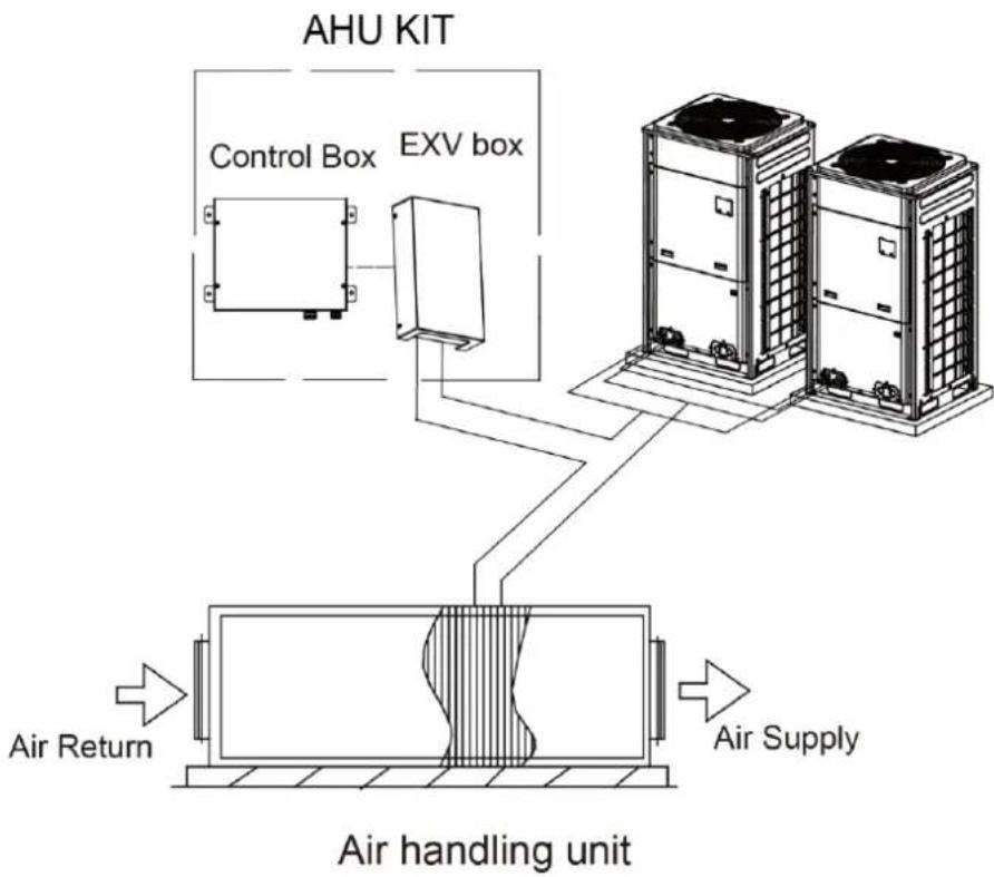
flowchart
graph TD
    A["AHU KIT"] --> B["Control Box"]
    A --> C["EXV box"]
    B --> D["Air handling unit"]
    C --> D
    D --> E["Air Supply"]
    F["Air Return"] --> D
    style A fill:#f9f,stroke:#333
    style B fill:#ccf,stroke:#333
    style C fill:#ccf,stroke:#333
    style D fill:#cfc,stroke:#333
    style E fill:#fcc,stroke:#333
Fig.2.5.2 AHU-KIT one-to-one (combination outdoor unit) connection diagram
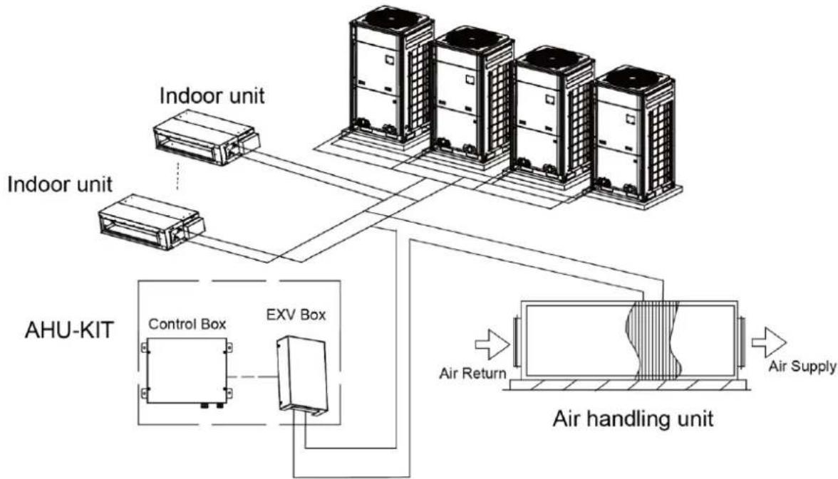
flowchart
graph TD
    A["Indoor unit"] --> B["AHU-KIT"]
    C["Indoor unit"] --> B
    D["Control Box"] --> E["EXV Box"]
    F["Air Handling unit"] --> G["Air Supply"]
    B --> H["Air Return"]
    E --> H
    G --> H
Fig.2.5.3 AHU-KIT one-to-more (hybrid connection) connection diagram
3 Preparations for Installation
3.1 Before Installation
NOTICE!
Product graphics are only for reference. Please refer to actual products. Unspecified measure unit is mm (in.).
(1) This equipment is designed for R410A system, and the designed working pressure is 3.8 MPa or 38 bar.
(2) Working Ambient Temp. Tmax=109F (45 °C).
(3) Precautions for R410A:
(4) a). The refrigerant requires strict cautions for keeping the system clean, dry and tight.
(5) —Clean and dry: Foreign materials (including mineral oils or moisture) should be prevented from getting mixed into the system.
(6) —Tight: Read this manual carefully and follow these procedures correctly.
(7) b). Since R410A is a mixed refrigerant, the required additional refrigerant must be charged in its liquid state. (If the refrigerant is in state of gas, its composition changes and the system will not work properly).
(8) The connected air handling units must have heat exchangers designed exclusively for R410A.
(9) Never use this appliance in a place with inflammable and explosive gas.
(10) For the following items, take special care during construction and check after installation is finished:
| Tick √ when checked |
| □ Are the temperature sensors fixed firmly?□ Temperature sensor may come loose. |
| □ Is the capacity code set correctly?□ System performance may not reach relevant requirements or will lead to reliability problem. |
| □ Is the control box fixed firmly?□ The unit may drop, vibrate or make noise. |
| □ Do electrical connections comply with specifications?□ The unit may malfunction or components may burn out. |
| □ Are wiring and piping correct?□ The unit may malfunction or components may burn out. |
| □ Is the unit safely grounded?□ Dangerous at electric leakage. |
3.2 Location for Installation
Select an installation site where the following conditions are fulfilled and that meets your customer's approval.
(1) The EXV box can be installed inside and outside. The control box should be installed inside.
(2) Do not install the EXV box in or on the outdoor unit.
(3) Do not put the option boxes in direct sunlight. Direct sunlight will increase the temperature inside the option boxes and may reduce its lifetime and influence its operation.
(4) Choose a flat and strong mounting surface.
(5) Make sure there is enough free space in front and in the side of the AHU-KIT unit for future maintenance.
(6) The installation site should be far away from heat source, inflammable gas and smoke.
(7) Keep the air handling unit, power supply wiring and transmission wiring at least 1 m away from televisions and radios. This is to prevent image interference and noise in those electrical appliances (Noise may be generated depending on the conditions under which the electric wave is generated, even if 1 m is kept.).
(8) Make sure the electronic expansion valve is installed in an upright position.
| NOTICE |
| Do not install or operate the unit in rooms mentioned below:a) Where mineral oil, like cutting oil is present.b) Where the air contains high levels of salt such as air near the ocean.c) Where sulphurous gas is present such as that in areas of hot spring.d) In vehicles or vessels.e) Where voltage fluctuates a lot such as that in factories.f) Where high concentration of vapor or spray are present.g) Where machines generating electromagnetic waves are present.h) Where acidic or alkaline vapor is present. |
| Installing this unit must comply with the relevant local and national codes. |
| Connecting the power after all installation works are done. |
3.3 Requirements for Communication Wire
NOTICE!
If the unit is installed in the place with strong electromagnetic interference, shielded wire must be applied on the communication wire between indoor unit (AHU-KIT) and wired controller. Twisted pair wire with shielding function must be applied on the communication wire between indoor unit and indoor unit (outdoor unit).
3.3.1 Selecting communication wire for AHU-KIT and wired controller
| Wire type | Total length of communication wire between indoor unit and wired controller (m/ft.) | Wire diameter (AWG) | Remark |
| Light/Ordinary polyvinyl chloride sheathed cord. (60227 IEC 52/60227 IEC 53) | L≤250(850) | 2×18~2×16 | 1. Total length of communication cable can't exceed 250m (850ft.).2. The cord shall be Circular cord (the cores shall be twisted together).3. If unit is installed in places with intense magnetic field or strong interference, it is necessary to use shielded wire. |
Connection between AHU-KIT and wired controller is shown as follows
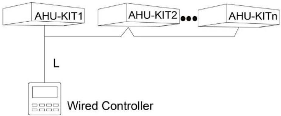
(1) When one AHU-KIT is connected to one AHU, you can adopt the connection ways of one wired controller to one AHU-KIT or one wired controller to several AHU-KITs (group control, n≤16).
(2) When several AHU-KITs are in parallel connection with one AHU, you can only adopt the way of one wired controller to several AHU-KITs (group control, n≤2).

text_image
AHU-KIT L Wired ControllerFig.3.3.1 one wired controller to one AHU-KIT
flowchart
graph TD
    A["AHU-KIT1"] --> C[" wired Controller "]
    B["AHU-KIT2"] --> C
    D["AHU-KITn"] --> C
    C --> E["L"]
Fig.3.3.2 one wired controller to several AHU-KITs
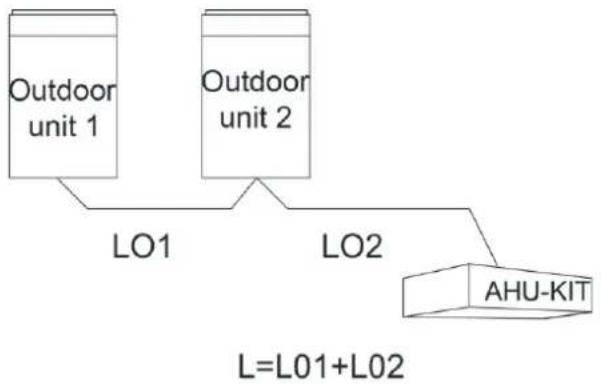
3.3.2 Select Communication wire for AHU-KIT and Outdoor Unit
flowchart
graph TD
    A["Outdoor unit 1"] --> B["LO1"]
    C["Outdoor unit 2"] --> D["LO2"]
    E["AHU-KIT"] --> D
    style E fill:#f9f,stroke:#333
    note right of E L=L01+L02
Fig.3.3.3
| Wire type | Total length of communication wire between indoor unit and indoor unit (outdoor unit) (m/ft.) | Wire diameter (AWG) | Remark |
| Light/Ordinary polyvinyl chloride sheathed cord. (60227 IEC 52 /60227 IEC 53) | L≤1000(3280) | ≥2×18 | 1. If the wire diameter is enlarged to 18AWG, the total communication cable length can reach 1500m (4920 ft.).2. The cord shall be Circular cord (the cores shall be twisted together).3. If unit is installed in places with intense magnetic field or strong interference, it is necessary to use shielded wire. |
3.4 Wiring Requirements
Power Cord Size and Air Switch Capacity:
| Model | Power Supply | Fuse Capacity(A) | Minimum Circuit Capacity(A) | Maximum Overcurrent Protection(A) |
| GMV-N12U/A-T(U) | 1-Ph 208/230V 60Hz | 15 | 10 | 15 |
| GMV-N24U/A-T(U) | 15 | 10 | 15 | |
| GMV-N48U/A-T(U) | 15 | 10 | 15 | |
| GMV-N96U/A-T(U) | 15 | 10 | 15 | |
| GMV-N192U/A-T(U) | 15 | 10 | 15 |
| NOTICE |
| Use copper wire only as unit's power cord. Operating temperature should be within its rated value. |
| 1 Above selection requirements: Power cord size is based on BV single-core wire (2~4pc) at 40°C(104°F)ambient temperature when laying across plastic pipe. Air switch is D type and used at 40°C(104°F). If actual installation condition varies, please lower the capacity appropriately according to the specifications of power cord and air switch provided by manufacturer. |
| 2 Install cut-off device near the unit. The minimum distance between each stage of cut-off device should be 3 mm (1/8 in) (The same for both indoor unit and outdoor unit). |
3.5 Piping Requirements
3.5.1 Selection of Piping Requirements
(1) Ensure the inside of the pipes is clean and no foreign materials.
(2) Pipe specifications:
| R410A System | ||
| Pipe Diameter mm(in.) | Wall Thickness mm(in.) | Temper grade of piping material |
| Φ6.35(1/4) | ≥0.8(1/32) | O |
| Φ9.52(3/8) | ≥0.8(1/32) | O |
| Φ12.70(1/2) | ≥0.8(1/32) | O |
| Φ15.9(5/8) | ≥1.0(3/76) | O |
| Φ19.05(3/4) | ≥1.0(3/76) | 1/2H |
| Φ22.2(7/8) | ≥1.2(1/21) | 1/2H |
| Φ28.6(1-1/8) | ≥1.2(1/21) | 1/2H |
| Φ34.90(1-3/8) | ≥1.3(2/39) | 1/2H |
| Φ41.30(1-5/8) | ≥1.5(1/17) | 1/2H |
3.5.2 Piping Design
When one AHU-KIT is connected to one AHU, the piping diagram is as follows:
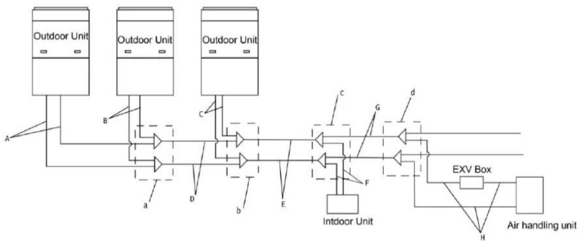
flowchart
graph TD
    A["Outdoor Unit"] --> B["Outdoor Unit"]
    B --> C["Outdoor Unit"]
    C --> D["Outdoor Unit"]
    D --> E["Intdoor Unit"]
    E --> F["EXV Box"]
    F --> G["Air handling unit"]
    style A fill:#f9f,stroke:#333
    style B fill:#f9f,stroke:#333
    style C fill:#f9f,stroke:#333
    style D fill:#f9f,stroke:#333
    style E fill:#ccf,stroke:#333
    style F fill:#cfc,stroke:#333
    style G fill:#fcc,stroke:#333
Fig.3.5.1 One AHU-KIT to one AHU
When several AHU-KITs are connected to one AHU, the piping diagram is as follows:
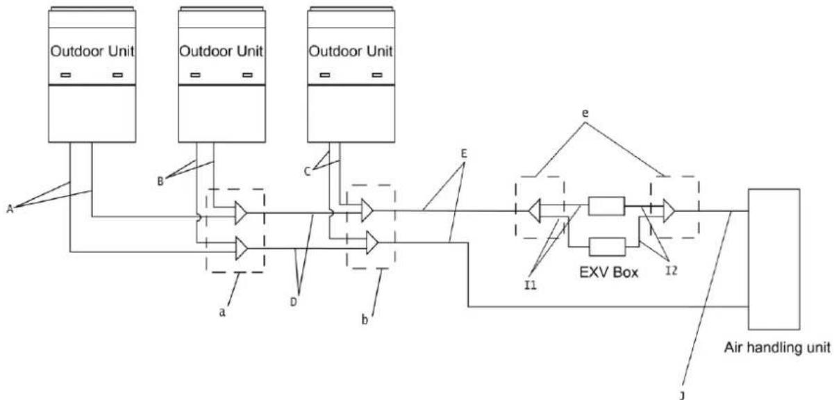
flowchart
graph LR
    A["Outdoor Unit"] --> B["Exterior"]
    B --> C["Outdoor Unit"]
    C --> D["Exterior"]
    D --> E["EXV Box"]
    E --> F["Air handling unit"]
    style A fill:#f9f,stroke:#333
    style B fill:#ccf,stroke:#333
    style C fill:#ccf,stroke:#333
    style D fill:#ccf,stroke:#333
    style E fill:#cfc,stroke:#333
    style F fill:#fcc,stroke:#333
    subgraph Air handling unit
        I1["11"] --> I2["12"]
        I2 --> e["e"]
        I2 --> b["b"]
        I2 --> D["D"]
        I2 --> a["a"]
        I2 --> B["B"]
    end
Fig.3.5.2 Several AHU-KITs to one AHU
3.5.2.1 Selection of Branch Pipe
(1) Branch pipes (a, b) between outdoor units shall be selected according to the total capacity of outdoor unit, as follows:
| Model | |
| Selection of branch pipe between ODU modules | ML01/A |
(2) Branch pipe (c, d) between indoor units shall be selected according to the total capacity of downstream IDUs, as follows:
| Selection of branch pipe between indoor units | Total rated capacity of downstream IDUs C(kBtu/h) | Model |
| Y-type Manifold | C<68 | FQ01A/A |
| 68≤C≤102 | FQ01B/A | |
| 102<F≤239 | FQ02/A | |
| 239<F | FQ03/A | |
| T- type Manifold | C≤136 | FQ14/H1 |
| C≤232 | FQ18/H1 | |
| 232<F | FQ18/H2 |
(3) When several AHU-KITs are connected to one AHU, branch pipe (e) shall be selected according to the following table:
| Model(Combined) | Branch pipe | Quantity |
| GMV-N48U/A-T(U)+GMV-N192U/A-T(U) | FQ01U/A | 1 |
3.5.2.2 Selection of Piping Dimension
Piping dimension can be selected according to the total rated capacity of upstream or downstream modules. Detailed requirements are as below:
(1) Piping (A, B, C) from ODU to branch pipe shall be selected according to the rated capacity of ODU;
(2) Piping D between branch pipes of ODU modules shall be selected according to the total rated capacity of upstream modules;
(3) Piping E and G of branch pipe at IDU side shall be selected according to the total rated capacity of downstream IDUs;
(4) Piping F from IDU branch pipe to IDU shall be selected according to the rated capacity of IDU;
(5) Piping (I1, I2, J, H) between branch pipe and AHU-KIT shall be selected according to the capacity of AHU-KIT.
Relationship between capacity and piping dimension is as below:
| Rated capacity (kBtu/h) | Gas pipe mm(in.) | Liquid pipe mm(in.) |
| Q≤72 | Φ19.05(3/4) | Φ9.52(3/8) |
| 72<Q≤96 | Φ22.2(7/8) | Φ9.52(3/8) |
| 96<Q≤120 | Φ28.6(1-1/8) | Φ12.7(1/2) |
| 120<Q≤144 | Φ28.6(1-1/8) | Φ12.7(1/2) |
AHU-KIT
| Rated capacity (kBtu/h) | Gas pipe mm(in.) | Liquid pipe mm(in.) |
| 144< Q≤168 | Φ28.6(1-1/8) | Φ15.9(5/8) |
| 168< Q≤216 | Φ28.6(1-1/8) | Φ15.9(5/8) |
| 216< Q≤240 | Φ34.9(1-3/8) | Φ15.9(5/8) |
| 240< Q≤312 | Φ34.9(1-3/8) | Φ19.05(3/4) |
| 312< Q≤336 | Φ34.9(1-3/8) | Φ19.05(3/4) |
| 336< Q≤360 | Φ41.3(1-5/8) | Φ19.05(3/4) |
NOTICE!
① As the capacity of AHU-KIT is adjustable, please select piping according to actual capacity in the project.
② If the ex-factory pipe diameter of AHU adapter is inconsistent with the actual required pipe diameter for the project, please conduct conversion or flaring treatment on site.
3.6 Capacity Setting
Capacity ranges of different AHU-KIT unit are as follows:
| Model | Acquiescent capacity (kBtu/h) | Adjustable capacity(kBtu/h) |
| GMV-N12U/A-T(U) | 12 | 9/12 |
| GMV-N24U/A-T(U) | 24 | 15/18/24 |
| GMV-N48U/A-T(U) | 48 | 30/36/48 |
| GMV-N96U/A-T(U) | 96 | 72/96/120/144 |
| GMV-N192U/A-T(U) | 192 | 168/192/288 |
Different capacities of same model of AHU-KIT unit are achieved through dialing capacity code of mainboard (shown as "S1"). Capacity code setting is shown as follows:
| S1 | Capacity (kBtu/h) | ||||
| 1 | 2 | 3 | 4 | 5 | |
| 0 | 1 | 0 | 0 | 0 | 9 |
| 0 | 0 | 1 | 0 | 0 | 12 |
| 0 | 1 | 1 | 0 | 0 | 15 |
| 0 | 0 | 0 | 1 | 0 | 18 |
| 0 | 1 | 0 | 1 | 0 | 24 |
| 0 | 0 | 1 | 1 | 0 | 30 |
| 0 | 1 | 1 | 1 | 0 | 36 |
| 0 | 0 | 0 | 0 | 1 | 48 |
| 1 | 1 | 0 | 0 | 1 | 72 |
| 1 | 0 | 1 | 0 | 1 | 96 |
| 0 | 1 | 1 | 0 | 1 | 120 |
| 0 | 0 | 0 | 1 | 1 | 144 |
| 0 | 1 | 0 | 1 | 1 | 168 |
| 1 | 1 | 0 | 1 | 1 | 192 |
| 0 | 0 | 1 | 1 | 1 | 288 |
Please ensure dialing the code switch properly in place instead of middle position. Setting the switch to "ON" stands for "0", otherwise stands for "1".
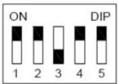
(Notes: The black part is the deflector rod.) The figure shows that the addresses of "1,2,3,4,5" are "0,0,1,0,0".
| NOTICE |
| 1 The selected air handling unit must be designed for R410A. |
| 2 Extraneous substances (including mineral oils or moisture) must be prevented from getting mixed into the system. |
4 Installation Instructions
4.1 Unit Dimensions and Maintenance Space
(1) Size of control box for GMV-N12U/A-T(U)、GMV-N24U/A-T(U)、GMV-N48U/A-T(U)、GMV-N96U/A-T(U) and GMV-N192U/A-T(U) (Unit: mm(in.)):
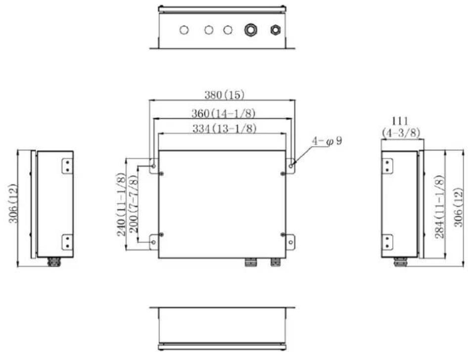
text_image
380 (15) 360 (14-1/8) 334 (13-1/8) 240 (11-1/8) 200 (7-7/8) 4-φ 9 111 (4-3/8) 284 (11-1/8) 306 (12)Fig.4.1.1
(2) Size of EXV box for GMV-N12U/A-T(U)、GMV-N24U/A-T(U)、GMV-N48U/A-T(U)、GMV-N96U/A-T(U) (Unit: mm(in.)):
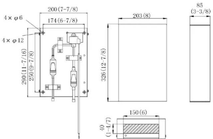
Fig.4.1.2
(3) Size of EXV box for GMV-N192U/A-T(U) (Unit: mm(in.)):
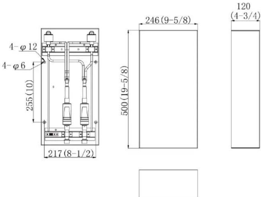
Fig.4.1.3
Maintenance space of control space (Unit: mm (in.)):
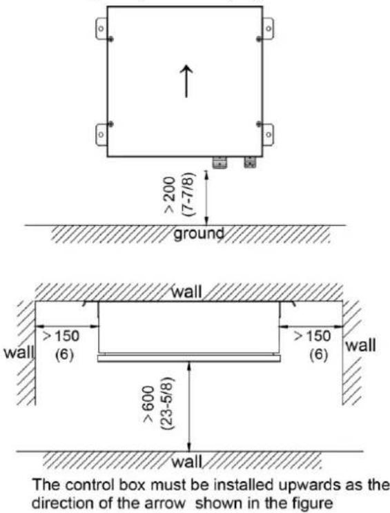
text_image
200 (7-7/8) ground wall >150 (6) >150 (6) >600 (23-5/8) wall The control box must be installed upwards as the direction of the arrow shown in the figureFig.4.1.4
Maintenance space of EXV box (Unit: mm (in.)):
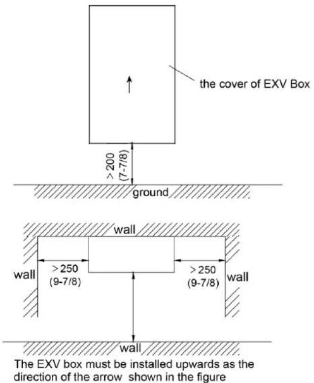
text_image
the cover of EXV Box >200 (7-7/8) ground wall >250 (9-7/8) >250 (9-7/8) wall wall The EXV box must be installed upwards as the direction of the arrow shown in the figureFig.4.1.5
4.2 EXV Installation
4.2.1 Mechanical Installation
(1) Remove the EXV box cover by unscrewing screws.
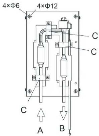
(2) Drill 4 holes on correct position (measurements as indicated in figure below) and fix the valve kit box securely with 4 screws through the provided holes 12mm(1/2 in.).
| NOTICE |
| 1 Make sure that the EXV box is installed upwards. |
| 2 Make sure there is enough free space in front and in the side of the box for future maintenance. |
4.2.2 Brazing Work
(1) Prepare the inlet/outlet field piping just in front of the connection (do not braze yet).
text_image
4×Φ6 4×Φ12 C C C A BFig.4.2.1
A: Inlet coming from the outdoor unit
B: Outlet to air handling unit
C: Wire clamp
(2) Remove the wire clamp (C) by unscrewing 6xM4.2.
(3) Braze the field piping.
| NOTICE |
| (1) Make sure there is nitrogen protection during welding.Brazing without carrying out nitrogen replacement or releasing nitrogen into the piping will create large quantities of oxidized film on the inside of the pipes, adversely affecting valves and compressors in the refrigerating system and preventing normal operation. |
(2) When brazing while inserting nitrogen into the piping, nitrogen must be set to 0.02 MPa with a pressure-reducing valve (=just enough so that it can be felt on the skin).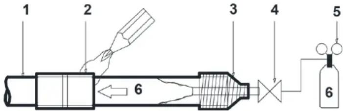 1) Refrigerant piping2) Part to be brazed3) Taping4) Hands valve5) Pressure-reducing valve6) NitrogenFor details, see manual of the outdoor unit. 1) Refrigerant piping2) Part to be brazed3) Taping4) Hands valve5) Pressure-reducing valve6) NitrogenFor details, see manual of the outdoor unit. |
| (3) Make sure to cool the filters and valve body with a wet cloth and make sure the body temperature does not exceed 120°C(248°F) during brazing. |
| (4) Make sure that the other parts such as electrical box, tie wraps and wires are protected from direct brazing flames during brazing. |
| (5) The EXV box is required to be installed in a vertical direction within the range of 90±15° (not allowed for horizontal work). Welding the connection tubes first before refrigerant pipes in order to avoid face-down soldering. |
| (6) All field piping must be provided by a licensed refrigeration technician and must comply with the relevant local and national codes.a) For refrigerant piping of outdoor unit, refer to the installation manual supplied with the outdoor unit.b) The maximum allowed piping length depends on the connected outdoor model. |
(4) Secure the wire clamp (C) in place again (6xM4.2).
(5) Make sure that field pipes are fully insulated. Make sure that there is no gap between both ends in order to avoid condensation dripping (finish the connection with tape eventually).
4.2.3 Installation handbook of the EXV cable
4.2.3.1 Installation steps
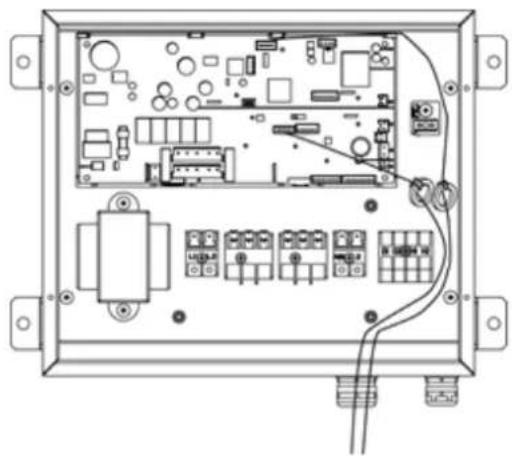
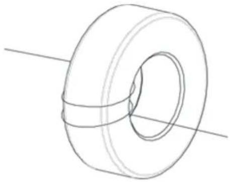
(1) Making the cable terminal through the Cable-Cross Loop (Fig.4.2.2), and then winding the cable on the magnetic ring for three times (Fig.4.2.3), at last inserting the terminal into a corresponding slot (see circuit diagram).
(2) Using bundles to fix the magnetic ring is required. It's also need to insert the bundle into
the reserved hole on the control box.
(3) Fixing the cable with the wire clamp, and tightening the Cable-Cross Loop.
(4) Fix the magnetic ring to the reserved hook fixing inside electrical box with high-temperature bonding tie.
(5) Screw the joint.
4.2.3.2 Installation requirements
(1) Ensure that the cable in the control box is in a relaxed state, and both the joint of terminal and the fixed place of magnetic ring are all not under a stress.
(2) Ensure that the cable sheath port is located in the control box in order to prevent the rain.
natural_image
Interior view of an electronic device casing with circuit boards, connectors, and wiring (no visible text or labels)Fig.4.2.2
natural_image
Line drawing of a toroidal mechanical component with a central hole and side grooves (no text or symbols)Fig.4.2.3
4.3 Installation of the EXV Cable
Referring to the circuit diagram, then connect the EXV cable to the circuit-board of control box. Be sure that the cable is fixed firmly in order to ensure a good pull relieve and water protection.
4.4 Piping Installation
When one AHU-KIT is connected to one AHU, the piping installation diagram is as follows:
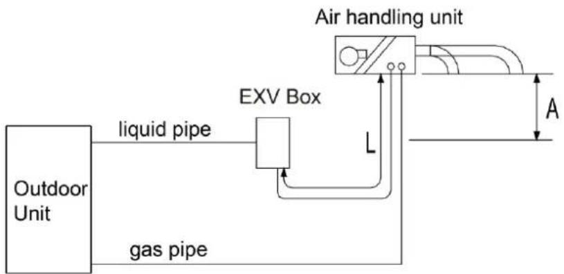
flowchart
graph LR
    A["Outdoor Unit"] -->|liquid pipe| B["EXV Box"]
    B --> C["Air handling unit"]
    C -->|A| D["Horizontal line"]
    B -->|L| C
    style A fill:#f9f,stroke:#333
    style B fill:#ccf,stroke:#333
    style C fill:#cfc,stroke:#333
Fig.4.4.1
When several AHU-KITs are connected to one AHU, the piping installation diagram is as follows:
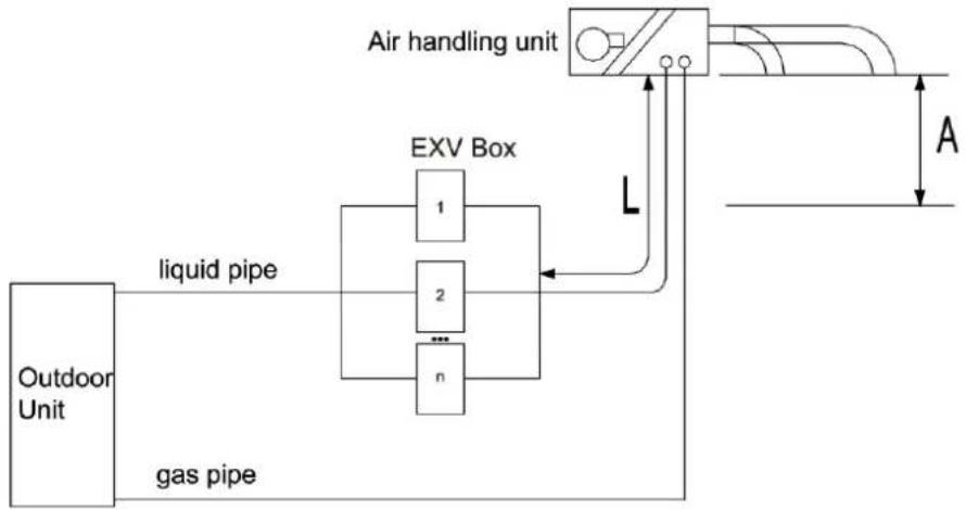
flowchart
graph TD
    A["Outdoor Unit"] -->|liquid pipe| B["EXV Box"]
    A -->|gas pipe| B
    B --> C["Air handling unit"]
    C -->|L| B
    B --> D["A"]
Fig.4.4.2
NOTICE!
A: When the air handling unit is installed at the top of the EXV box, vertical distance between the bottom of the air handling unit to the EXV box is no more than 2 m; if the air handling unit is installed under the EXV box, vertical distance between the bottom of the air handling unit to the EXV box is no more than 2 m.
L: The length of liquid pipe between the air handling unit to EXV box is no more than 2 m.
L is to be considered as a part of the total maximum piping length. See installation manual of the outdoor unit for piping installation.
4.5 Installation of the Control Box
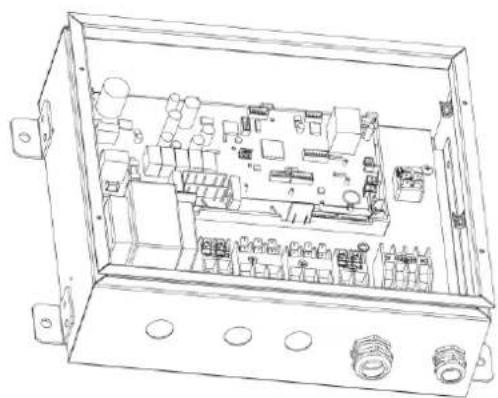
natural_image
Technical line drawing of an open electrical enclosure with internal components and mounting holes (no text or labels)Fig.4.5.1
(1) Fix the control box with its hanger brackets to the mounting surface.
(2) Open the lid of the control box.
(3) For electrical wiring: refer to the following contents.
(4) Install the screw nuts.
(5) Close the unnecessary openings.
(6) Close the lid securely after installation to ensure that the control box is watertight.
4.5.1 Wire connection Inside the Control Box
4.5.1.1 Wire connection of single AHU-KIT control part
NOTICE!
Put through the wires to the coil, tighten the coil while maintaining loose condition of wires to ensure it is not closely tied up and is waterproof.
text_image
Technical diagram showing electrical connection with labeled components and wiring connectionsFig.4.5.2
Precautions:
① Temperature sensor cable and remote controller wire should be kept away from power cable in a distance of at least 50(mm). Violating this rule may generate electric noise and lead to malfunctions.
② Use wires as specified and connect them tightly with wiring terminals. Keep the wires in order and do not obstruct other devices. Insecure connection may result in overheating or even cause electric shock or fire hazard.
Wiring connection:
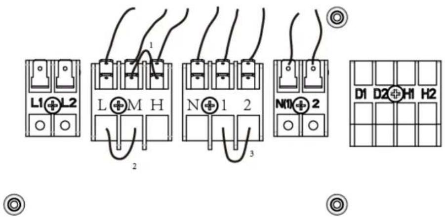
text_image
L1+L2 L+M H N+1 2 N10+2 D1 D2+H1 H2Fig.4.5.3
Connecting cables according to the following instructions, as figure shown above.
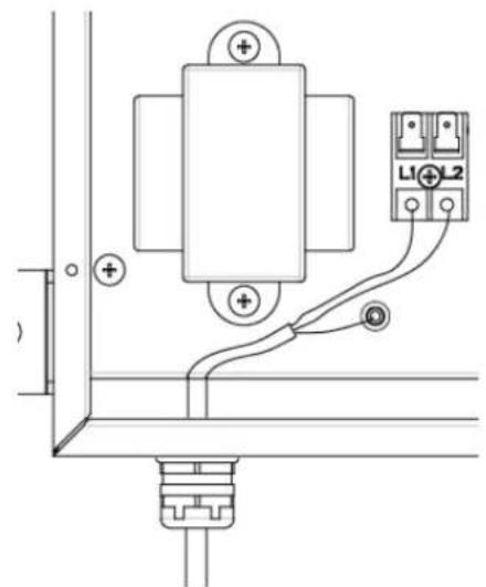
L1: Live
L2: Live

Protective earth (screw)
L: Low gear of fan
M: Middle gear of fan
H: High gear of fan
1/2: Lines of fault signal from external feedback
N (1)/2: Secondary transformer
D1/D2: Communication wires
H1/H2: Wired controller
| NOTICE |
| 1 The H, M, L of fan gear lines and the 1, 2 of Lines of fault signal from external feedback are shorted by the factory default. |
| 2 Neutral line of fan connects to the N.It can be connected to any of them (H, M, L) when there is only one gear.Disconnect the short cable between H and M when there are two gears, then connect the high gear cable to H, and connect low gear cable to either M or L.When there are three gears, disconnect the short cables between H and M, M and L, then connect the high gear cable, middle gear cable and low gear cable to H,M,L for each. |
| 3 The lines of fault signal from external feedback are connected to the 1, 2.The line is a dry contact and closed normally. If the line is closed, it represents no fault and the system operates normally; if the line is disconnected, it represents malfunction and the system will stop. |
| 4 Disconnect the short cable between 1 and 2 when there is fault signal, and connect the signal cable to 1 and 2. |
| 5 Pull the wires inside through the screw nut and close the nut firmly in order to ensure a good pull relieve and water protection. |
| 6 Connect the fan cable of IDU and fan error information cable to either AHU-KIT. |
| 7 Put through the wires to the coil, tighten the coil while maintaining loose condition of wires to ensure it is not closely tied up and is waterproof. |
| 8 When power supply is 208V, connect the preliminary transformer to the red and blue wires according to circuit diagram. When power supply is 230V, exchange the black wire on wiring board XT6 with the blue wire on wiring board XT3. Provide a voltage of 24V for secondary transformer under these two situations. Please note that transformer function is available only when the fan is in “1” notch. |
4.5.1.2 Wire connection of multiple AHU-KIT control parts
When multiple AHU-KITs control an air handling unit, connect fan control wire and external signal feedback signal wire of air handling unit to any one AHU-KIT. Please refer to the wiring method of AHU-KIT for the connection method.
4.6 Installation of the Temperature sensors
4.6.1 Refrigerant Temperature sensors
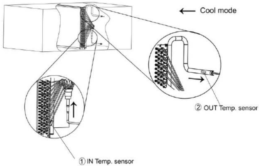
Location of the temperature sensor: A correct installation of the temperature sensors is required to ensure a good operation.
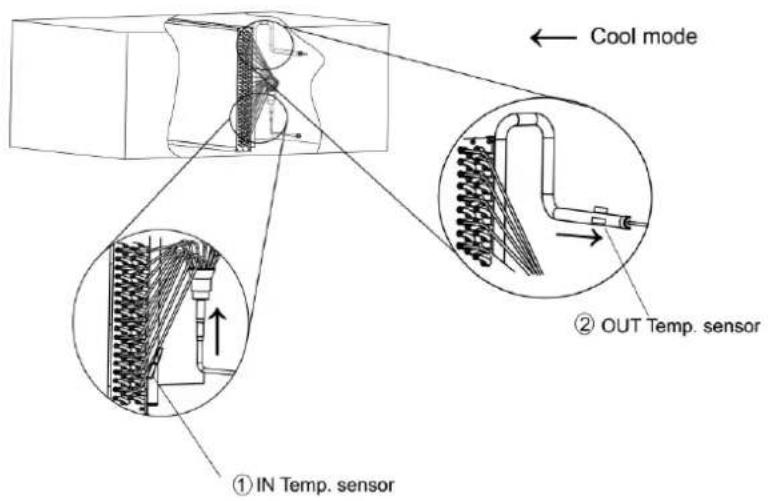
(1) IN Temp. sensor(Liquid Temp. sensor)
Install the IN temperature sensor after the distributor and on the coldest temperature pipe of a heat exchanger.
(2) OUT Temp. sensor (Gas Temp. sensor)
Install the OUT temperature sensor 200mm after the outlet of the heat exchanger.
text_image
Cool mode ① IN Temp. sensor ② OUT Temp. sensorFig.4.6.1
① IN Temp. sensor (Liquid Temp. sensor)
② OUT Temp. sensor (Gas Temp. sensor)
Installation of the temperature sensor cable:
(1) The length of temperature sensor wire is 10 m.
(2) Put the temperature sensor cable in an individual protective tube.
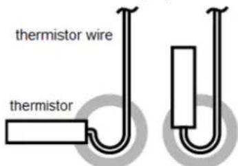
(3) Apply stress release in the temperature sensor wire to prevent the temperature sensor wire from getting loose due to stress. Stress or looseness of temperature sensor wire will lead to poor contact and inaccuracy of temperature measuring. Fixation of the temperature sensor
NOTICE
① Put the temperature sensor wire slightly down to avoid water accumulation on top of the temperature sensor.
text_image
thermistor wire thermistor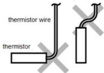
text_image
thermistor wire thermistor② Keep the temperature sensor and air handling unit in good contact. Put the top of the temperature sensor on the air handling unit, because the top of temperature sensor is the most sensitive part. Please fixing the temperature sensor on the horizontal plane of copper tube (within ± 30^ ), and make them close together.
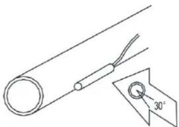
natural_image
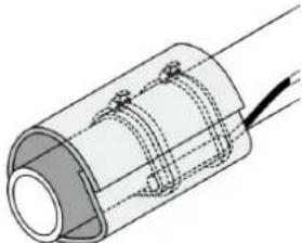
Simple line drawing of a cylindrical object with a wire and a 30-degree angle label (no text or symbols beyond the angle marker)③ Fix the temperature sensor with insulating aluminum tape in order to ensure good heat transference.
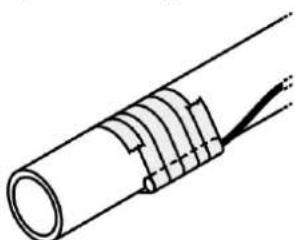
natural_image
Diagram of a cylindrical cable with internal bands and a connecting rod (no text or symbols)④ Cover the temperature sensor with rubber belt to prevent looseness of temperature sensor.
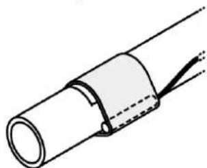
natural_image
Diagram of a cylindrical pipe with a coiled cable and wire, showing internal structure (no text or symbols)| NOTICE | |
| 5 Use two wire ties to bind the temperature sensor securely. | |
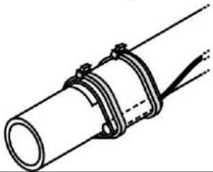 | |
| 6 Wrap the temperature sensor with insulating trip. | |
 |
4.6.2 Air Temperature sensor
The air temperature sensor can be installed in the space which needs temperature control, or the inlet scoop of air handling unit.
| NOTICE |
| 1 For connection to outdoor unit and to AHU-KIT unit: Pull the wires inside through the screw nut and close the nut firmly in order to ensure a good pull relieve and water protection. |
| 2 The cables require an additional pull relief. Fixing the cable with the wire clamp. |
| 3 The connection of temperature sensor requires enough space. |
4.6.3 Installation of Temperature Sensor when Several AHU-KITs are in Parallel Connection with One AHU
When several AHU-KITs are in parallel connection with one AHU, all linkage AHU-KIT inlet pipes' and outlet pipes' temperature sensor must be installed at the position of corresponding pipeline of air handling unit. Install the ambient temperature sensor at the same position of air return outlet. Please refer to above installation method of single AHU-KIT temperature sensor. The installation diagram is as below:
text_image
Cool mode ① IN Temp. sensor ② OUT Temp. sensorFig.4.6.2
① IN Temp. sensor (Liquid Temp. sensor)
② OUT Temp. sensor (Gas Temp. sensor)
4.7 Installation of Wired Controller
Please refer to User Manual of Wired Controller for the installation details.
NOTICE!
When installation is finished, the unit must be tested and debugged before operation. Please refer to Instruction Manual of ODU for auto addressing and debugging details.
5 Wire Connection
| NOTICE |
| 1 Units must be earthed securely, or it may cause electric shock. |
| 2 Please carefully read the wiring diagram before carry out the wiring work, incorrect wiring could cause malfunction or even damage the unit. |
| 3 The capacity of power supply should be big enough. |
| 4 The unit should be powered by independent circuit and specific socket. |
| 5 The wiring should be in accordance with related regulations in order to ensure the units reliable running. |
| 6 Install circuit breaker for branch circuit according to related regulations and electrical standards. |
| 7 All wiring must use pressure terminal or single wire. Multi-twisted wire that connects directly to the wiring board may cause fire hazard. |
| 8 Keep cable away from refrigerant piping, compressor and fan motor. |
| 9 Do not alter the inner wires of air conditioner. Manufacturer does not assume responsibility for damage or abnormal operation due to this reason. |
| 10 If the unit is installed in places with strong electromagnetic interference, it's recommended to use twin-twisted shield wire. During wire connection, please pay attention that the metal shield layer of the twin-twisted wire must be grounded (outer case) in order to prevent the unit from electromagnetic interference. |
| 11 The communication wires should be separated from power cord and connection wire between indoor unit and outdoor unit. |
| 12 The appliance shall be installed in accordance with national wiring regulations |
| 13 For security, it is suggested that the exposed wires of EXV and temperature sensors wrapped in insulated tubes for good isolation. |
5.1 Connect Cables and Terminals of Wiring Board
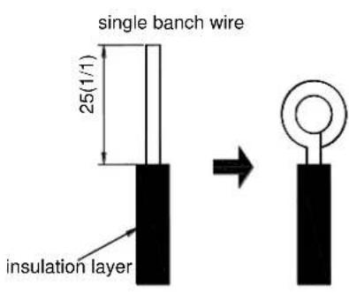
(1) Connection of Wire and Patch Board Terminal (as shown in fig.5.1.1)
1) Strip about 25mm insulation of the wire end by stripping and cutting tool.
2) Remove the wiring screws on the terminal board.
3) Shape the tail of wire into ring by needle nose plier, and keep the gauge of ring in accordance with screw.
4) Use the screwdriver for tightening the terminal.
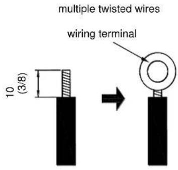
(2) The connection of stranded wire (as shown in fig.5.1.2)
1) Strip about 10mm insulation of the end of stranded wire by stripping and cutting tool.
2) Loosen the wiring screws on terminal board.
3) Insert the wire into the ring tongue terminal and tighten by crimping tool.
4) Use the screwdriver for tightening the terminal.
text_image
single banch wire 25(1/1) insulation layerFig.5.1.1
text_image
multiple twisted wires wiring terminal 10 (3/8)Fig.5.1.2
5.2 Power Cord Connection
NOTICE!
Each indoor unit must be installed with a independent circuit breaker for short-circuit protection and overload protection. In general, this circuit breaker is under close status.
During operation process, all indoor units and outdoor units in one system must be energized. Otherwise, the system can't operation normally.
Power supply of each indoor unit must be from the same source.
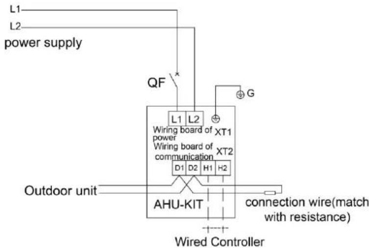
Power connection diagram for one AHU-KIT connected to one AHU:
text_image
L1 L2 power supply QF L1 L2 XT1 Wiring board of power Wiring board of communication XT2 D1 D2 H1 H2 Outdoor unit AHU-KIT connection wire(match with resistance) Wired ControllerFig.5.2.1
For units with single-phase power supply:
(1) Detach the electric box lid.
(2) Let the power cord pass through the wiring through-holes.
(3) Connect the power cord to terminal "L1, L2, ⊕".
(4) Fix the power card with wiring clamp.
Power connection diagram for several AHU-KITs in parallel connection with one AHU:
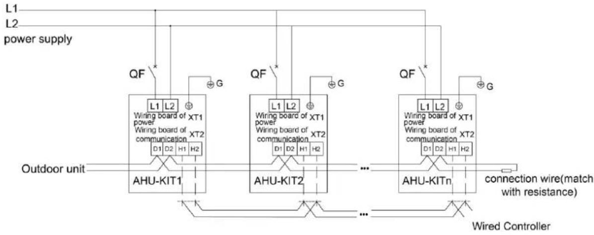
flowchart
graph TD
    A["Power Supply"] --> B["Wiring Board of Power"]
    B --> C["XT1"]
    B --> D["XT2"]
    B --> E["QF*"]
    E --> F["Wiring Board of Communication"]
    F --> G["XT1"]
    F --> H["XT2"]
    F --> I["QF*"]
    I --> J["Wiring Board of Power"]
    J --> K["XT1"]
    J --> L["XT2"]
    J --> M["QF*"]
    M --> N["Wiring Board of Communication"]
    N --> O["XT1"]
    N --> P["XT2"]
    N --> Q["QF*"]
    Q --> R["Wiring Board of Power"]
    R --> S["XT1"]
    R --> T["XT2"]
    R --> U["QF*"]
    U --> V["Wiring Board of Communication"]
    V --> W["XT1"]
    V --> X["XT2"]
    V --> Y["QF*"]
    Y --> Z["Wired Controller"]
    AA["Outdoor unit"] --> AB["AHU-KIT1"]
    AB --> AC["..."]
    AC --> AD["AHU-KIT2"]
    AD --> AE["..."]
    AE --> AF["AHU-KITn"]
    AF --> AG["connection wire (match with resistance)"]
    AH["Wired Controller"] --> AI["..."]
Fig.5.2.2
For units with single-phase power supply:
(1) Detach the electric box lid.
(2) Let the power cord pass through the wiring through-holes.
(3) Connect the power cord to terminal "L1, L2, ⊕".
(4) Fix the power card with wiring clamp.
5.3 Connection of Communication Wire between Indoor Unit and Outdoor Unit (or Indoor Unit)
Detach the control box lid.
(1) Let the Communication cable pass through the wiring through-holes.
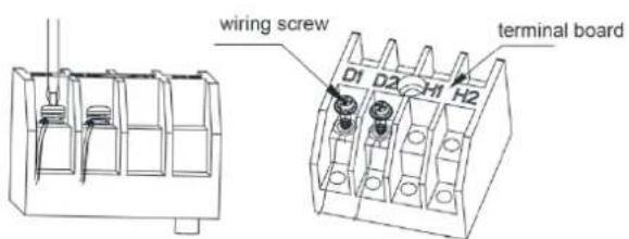
(2) Connect the communication wire to terminal D1 and D2 of indoor 4-bit wiring board, as shown in fig.5.3.1.
(3) Fix the communication cable with clamp of electric box.
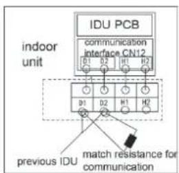
(4) For more reliable communication, make sure connect the terminal resistor to the most downstream IDU of the communication bus (terminal D1 and D2), as shown in fig 5.3.2, terminal resistor is provided with each ODU.
text_image
wiring screw D1 D2 H1 H2 terminal boardFig.5.3.1
flowchart
graph TD
    A["INDU PCB"] --> B["communication Interface CN12"]
    B --> C["previous IDU"]
    C --> D["match resistance for communication"]
    style A fill:#f9f,stroke:#333
    style B fill:#ccf,stroke:#333
    style C fill:#cfc,stroke:#333
    style D fill:#fcc,stroke:#333
Fig.5.3.2
5.4 Connect Communication Wire of Wired Controller
(1) Open electric box cover of indoor unit.
(2) Let the communication wire go through the rubber ring.
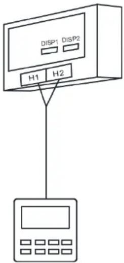
(3) Connect the communication wire to terminal H1 and H2 of indoor 4-bit wiring board.
(4) Fix the communication wire with wire clip on the electric box.
(5) Wiring instructions of remote receiving light board and wired controller:
Fig.5.4 shows the installation of wired controller:
text_image
DISP1 DISP2 H1 H2Fig.5.4
5.5 Illuminate for Connection of Wired Controller and Indoor Units
(AHU-KIT) Network
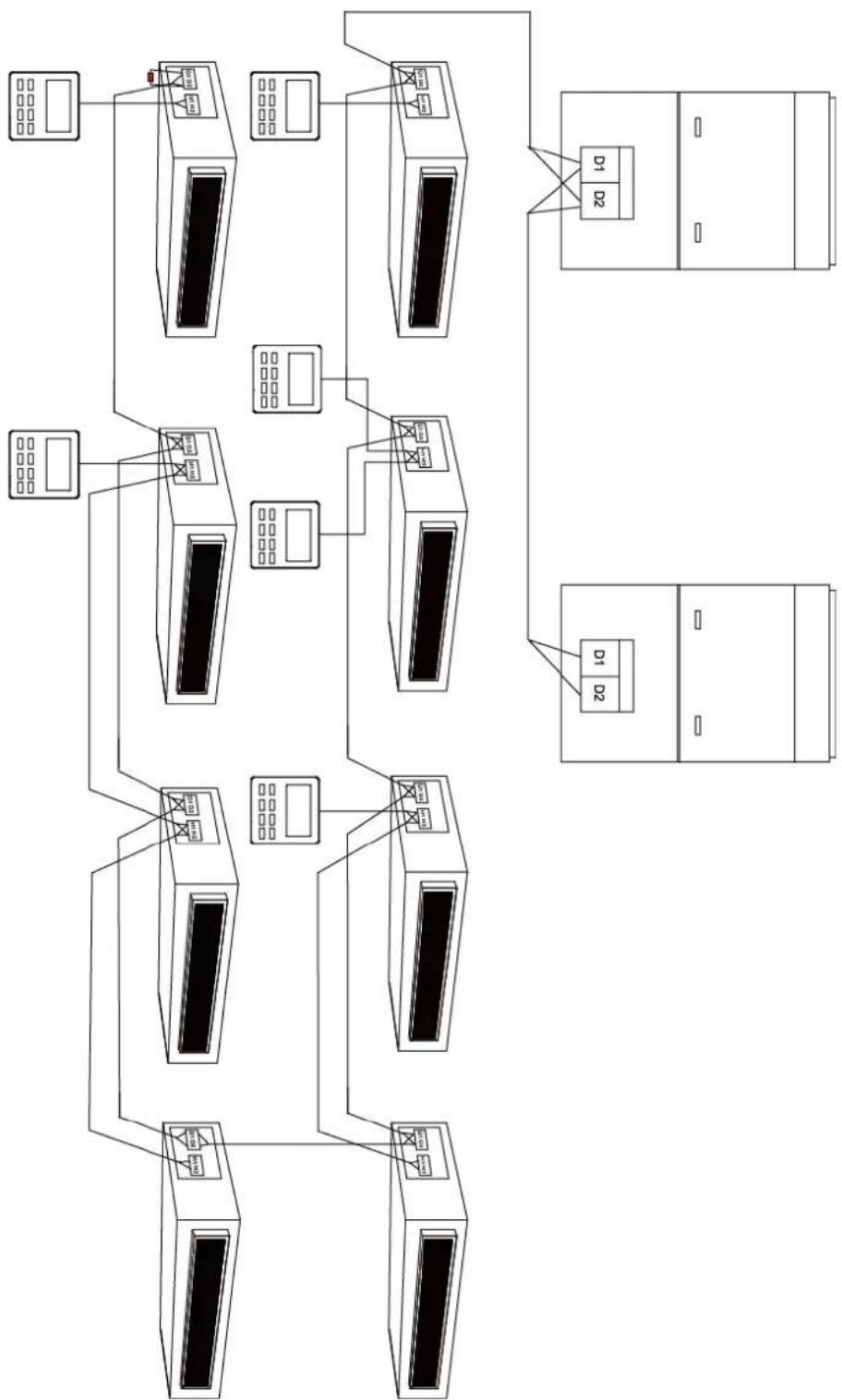
(1) Communication wire of indoor unit and outdoor unit (or indoor unit) is connected to D1, D2.
(2) Wired controller is connected to H1, H2.
(3) One indoor unit can connect two wired controllers that must be set as master one and slave one.
(4) One wired controller can control 16 indoor units in maximum at the same time (as shown in fig.5.5).
NOTICE
(1) The type of indoor units must be the same if they are controlled by the same wired controller.
(2) When the indoor unit is controlled by two wired controllers, the addresses of the two wired controllers should be different through address setting. Address 1 is for main controller; Address 2 is for slave controller. Detailed setting please refer to the instruction manual of wired controller.
flowchart
graph TD
    A["Client 1"] --> B["Server"]
    C["Client 2"] --> B
    D["Client 3"] --> B
    E["Client 4"] --> B
    F["Client 5"] --> B
    G["Client 6"] --> B
    H["Client 7"] --> B
    I["Client 8"] --> B
    J["Client 9"] --> B
    K["Client 10"] --> B
    L["Client 11"] --> B
    M["Client 12"] --> B
    N["Client 13"] --> B
    O["Client 14"] --> B
    P["Client 15"] --> B
    Q["Client 16"] --> B
    R["Client 17"] --> B
    S["Client 18"] --> B
    T["Client 19"] --> B
    U["Client 20"] --> B
    V["Client 21"] --> B
    W["Client 22"] --> B
    X["Client 23"] --> B
    Y["Client 24"] --> B
    Z["Client 25"] --> B
    AA["Client 26"] --> B
    AB["Client 27"] --> B
    AC["Client 28"] --> B
    AD["Client 29"] --> B
    AE["Client 30"] --> B
    AF["Client 31"] --> B
    AG["Client 32"] --> B
    AH["Client 33"] --> B
    AI["Client 34"] --> B
    AJ["Client 35"] --> B
    AK["Client 36"] --> B
    AL["Client 37"] --> B
    AM["Client 38"] --> B
    AN["Client 39"] --> B
    AO["Client 40"] --> B
    AP["Client 41"] --> B
    AQ["Client 42"] --> B
    AR["Client 43"] --> B
    AS["Client 44"] --> B
    AT["Client 45"] --> B
    AU["Client 46"] --> B
    AV["Client 47"] --> B
    AW["Client 48"] --> B
    AX["Client 49"] --> B
    AY["Client 50"] --> B
Fig.5.5
6 Statement on linkage function setting
When several AHU-KITs are in parallel connection with one AHU, you must activate linkage function after installation for normal operation. Setting way is as below:
Step 1: Set group control IDU quantity
After making sure all AHU-KITs are energized, set AHU-KIT quantity through wired controller P14, detailed operation is as follows:
Under on or off status, press "Function" button for 5s to enter into the first level menu interface; Under parameter code "C00" status, (after pressing "Mode" button for three times" press "Function" button for 5s to enter into the second level menu. The temperature area displays "P00". Press "▲" and "▼" button can swing to the second level parameter code. Enter P14 engineer debugging interface, the top right corner of the interface will display "01", which means the number of AHU-KIT under the control of wired controller is 1, short press "Mode", and revise actual controlled AHU-KIT quantity through pressing "▲" and "▼" button, If two AHU-KITs are in parallel connection, please set 02, short press "Confirmed/Cancel" button, the setting is successful.
Step 2: Linage function startup setting. The operation is as below:
Operate it according to above operation to enter P53 engineer debugging interface, the top right corner of the interface will display “00”, which means AHU-KIT linkage function is invalid; short press “Mode”, and conduct revision through pressing “▲” and “▼” button, set “01”, which means AHU-KIT linkage function is valid, short press “Confirmed/Cancel” button, the setting is successful.
7 Operation and Maintenance
7.1 Before Operation
| NOTICE |
| 1 Before initiating operation, please read the operation manuals of outdoor unit, AHU-KIT unit and the air handling unit carefully. |
| 2 Refer to the installation manuals of the outdoor unit, AHU-KIT unit and the remote controller about settings of unit. |
7.2 Test Operation
Before executing "test operation" as well as before operating the unit, you must check the following:
(1) Refer to the section of "For the following items, take special care during construction and check after installation is finished".
(2) Ensure the construction of refrigerant piping, drain piping and electric wiring are finished.
(3) Check everything written in the installation manuals of the outdoor unit, AHU-KIT unit and the air handling unit.
(4) Open the gas side stop valve.
(5) Open the liquid side stop valve.
(6) Executing the test operation:
(7) Referring to the manuals of the outdoor unit and the air handling unit.
(8) Confirm that the fan of the air handling unit is ON.
7.3 Routine Maintenance
| NOTICE |
| 1 Only a qualified service person is allowed to perform maintenance. |
| 2 Before obtaining access to terminal devices, all power supply circuits must be interrupted. |
| 3 Water or detergent may deteriorate the insulation of electronic components and result in burn-out of these components. |
| 4 Stand at solid table when cleaning the unit. |
| 5 Do not clean the unit with hot water whose temperature is higher than 45 °C to prevent fade or deformation. |
| 6 Clean the filter with a wet cloth dipped in neutral detergent. |
| 7 Please contact after-sales service staff if there is abnormal situation. |
7.3.1 Maintenance Before the Seasonal Use
(1) Check if the air inlet and air outlet of indoor and outdoor unit are blocked.
(2) Check if securely grounded.
(3) Check if all the power cord and communication cable are securely connected.
(4) Check if any error code displayed after energized.
7.3.2 Maintenance After the Seasonal Use
(1) Set the unit in fan mode for half a day in a sunny day to dry the inner part of unit.
(2) When the unit won't be used for a long time, please cut off power supply for energy saving; the characters on the wired controller screen will disappear after cutting off the power supply.
7.4 Disposal Requirements
Dismantling of the unit, treatment of the refrigerant, of oil and of other parts must be done in accordance with relevant local and national legislation.
8 Table of Error Codes for Indoor Unit
| Error Code | Content | Error Code | Content | Error Code | Content |
| L0 | Indoor Unit Error | L9 | Quantity Of Group Control Indoor Units Setting Error | d8 | Water Temperature Sensor Error |
| L1 | Error From External Feedback | LA | Indoor Units Incompatibility Error | d9 | Jumper Cap Error |
| L2 | E-heater Protection | LH | Low Air Quality Warning | dA | Indoor Unit Hardware Address Error |
| L3 | Water Full Protection | LC | Outdoor-Indoor Incompatibility Error | dH | Wired Controller PC-Board Error |
| L4 | Wired Controller Power Supply Error | d1 | Indoor Unit PC-Board Error | dC | Capacity DIP Switch Setting Error |
| L5 | Anti-Frosting Protection | d3 | Ambient Temperature Sensor Error | dL | Outlet Air Temperature Sensor Error |
| L6 | Model Conflict | d4 | Inlet Piping Temperature Sensor Error | dE | Indoor Unit CO2 Sensor Error |
| L7 | No Master Indoor Unit Error | d6 | Outlet Piping Temperature Sensor Error | C0 | Communication Error |
| L8 | Power Insufficiency Protection | d7 | Humidity Sensor Error | AJ | Filter Cleaning Reminder |
| db | Special Code: Field Debugging Code | ||||
9 Troubleshooting
If your air conditioner is not working well, please check the following table first before asking for service:
| Phenomenon | Troubleshooting |
| The unit can’t start. | 1 No power supply.2 Circuit breaker is tripped because of current leakage.3 Circuit voltage is too low.4 ON/OFF key sets at the stop position.5 Failure in control system. |
| The unit stops after running for a while. | 1 Obstacle in front of the condenser.2 Abnormal operation of the control system.3 Outdoor temperature is higher than 43°C(109°F) when cooling mode is used. |
| Poor cooling effect. | 1 Air filter is dirty or blocked.2 Too many heating sources or people in the room.3 Doors or windows are open.4 Obstacle at the air intake and outlet of the unit.5 Setting temperature is too high or refrigerant is insufficient (e.g. refrigerant leakage).6 Poor performance of the indoor temperature sensor. |
| Poor heating effect. | 1 Air filter is dirty or blocked.2 Doors or windows are open.3 Wrong temperature setting (too low).4 Refrigerant leakage.5 Outdoor temperature is lower than -5°C(23°F).6 Abnormal operation of the control system. |
| Indoor fan doesn’t start up during heating. | 1 Improper location of tube sensor.2 The tube sensor inserts not well.3 The wiring of tube sensor is broken.4 Electricity leakage of capacitor. |
NOTICE!
If air conditioner still fails to work normally after checking and handling as described above, please stop using it immediately and contact local service center for assistance.
natural_image
Architectural structure with curved roof and window patterns, no visible text or symbols
GREE
GREE ELECTRIC APPLIANCES, INC. OF ZHUHAI
Add: West Jinji Rd, Qianshan, Zhuhai, Guangdong, China, 519070
Tel: (+86-756) 8522218
Fax: (+86-756) 8669426
E-mail: gree@gree.com.cn www.gree.com

600005000895