
RD900-MOD-R - Remote control Irritrol - Free user manual and instructions
Find the device manual for free RD900-MOD-R Irritrol in PDF.


| Product Type | Irrigation System Controller (Remote-Ready) |
| Model | RD900-MOD-R (6-, 9-, or 12-station models) |
| Power Input (Outdoor) | 120 VAC 60 Hz, 30 VA (Domestic); 230/240 VAC 50 Hz, 30 VA (International) |
| Power Input (Indoor) | 24 VAC via plug-in transformer, 30 VA |
| Station Output | 24 VAC at 0.5A per station, 1.0A total maximum |
| Master Valve/Pump Output | 24 VAC at 0.375A |
| Fuse Protection | 2.0A Slow-blow fuse |
| Battery Backup | 9V alkaline (not included), maintains time/date up to 24 hours; non-volatile memory retains programs for years |
| Operating Temperature | 32°F to 140°F (0°C to 60°C) |
| Programs | 3 independent watering programs (A, B, C) with 3 start times each |
| Watering Schedules | Weekday, Skip Days (1–31 day interval), Odd/Even date, with Day Exclusion |
| Water Budget | Per program or monthly, 0% to 200% scaling |
| Rain Delay | 1 to 9 days |
| Station Delay | 0 seconds to 2 hours between stations |
| Pump Control | Per station and during station delay (on/off) |
| Stack/Overlap | Selectable: stack (one program/station at a time) or overlap (up to three simultaneously) |
| Manual Operations | Semi-automatic, manual station, and station test (1–10 min) |
| Diagnostic Circuit Breaker | Detects and bypasses shorted stations, displays "FUS" |
| Remote and Sensor Compatible | RJ-11 jacks for Irritrol handheld remote (R-100-KIT) and CLIMATE LOGIC weather sensor |
| Mounting | Indoor or outdoor cabinet; wall-mount with screws |
| Dimensions (approx.) | 10.5" x 8.5" x 3.5" (H x W x D) – typical for 12-station model |
| Weight (approx.) | 2.5 lbs (1.1 kg) – controller only |
| Cleaning and Maintenance | Clean exterior with dry cloth; replace fuse as needed; replace 9V battery annually |
| Spare Parts | 2A slow-blow fuse, 9V battery (user-provided) |
Frequently Asked Questions - RD900-MOD-R Irritrol
User questions about RD900-MOD-R Irritrol
0 question about this device. Answer the ones you know or ask your own.
Ask a new question about this device
Download the instructions for your Remote control in PDF format for free! Find your manual RD900-MOD-R - Irritrol and take your electronic device back in hand. On this page are published all the documents necessary for the use of your device. RD900-MOD-R by Irritrol.
USER MANUAL RD900-MOD-R Irritrol
Irrigation System Controller

User's Guide
- Setup
- Installation
- Programming
- Troubleshooting
- Indoor and Outdoor 6-, 9-, and 12-station Models
Table of Contents
Getting to Know your Rain Dial-R Controller 2
Getting Started....4
Battery Installation & Armchair Programming ....4
Overview: Control Module Interface....6
Overview: Internal Controller Components......8
Installation Procedures....10
Installing the Controller Cabinet 10
Connecting the Valve Control Wiring....10
Connecting a Rain Sensor (optional) ......12
Connecting a Remote Control Unit (optional) ......13
Connecting an Earth Ground Device ....14
Connecting the Power Source ....15
Controller Station Test Feature....17
Getting the Most From Your Rain Dial-R Controller ....18
What the Display Indicates....20
Programming Mode 20
Basic Programming Procedures....23
Setting the Current Time and Day 23
Setting the Valve Run Time Duration....23
Setting the Program Cycle Start Time(s)....24
Setting the Program Watering Day Schedule....24
Special Functions ......27
Rain Delay 27
Water Budget....27
Stack/Overlap 29
Station Delay 30
Pump Control During Station Delay 30
Pump Control Option....31
Diagnostic Circuit Breaker 31
Fuse Replacement....31
Manual Operations....32
Semi-Automatic Program Operation....32
Manual Station Operation....32
Clear Program Memory 33
Restore Factory Default Settings....34
Troubleshooting Guide....35
Contact Information......36
Specifications....36
FCC Rules ......37
Getting to Know your Rain Dial-R Controller
To take full advantage of your new Rain Dial-R controller, take a few moments to become familiar with its many features:
- Modular design – Provides easy access to valve connection terminals and battery storage. Snap-out design enables the control module to be easily removed for "Armchair Programming."
- CLIMATE LOGIC ^® ready - Built-in RJ-11 jack for direct connection of the CLIMATE LOGIC weather sensing system. (CLIMATE LOGIC automatically alters the controller's watering time based on the weather. Using the CLIMATE LOGIC accessory earns the Rain Dial-R controller the EPA WaterSense ^® label.)
- Remote control ready – Built-in RJ-11 jack for direct connection to Irritrol R-100-KIT handheld remote control systems.
- Non-volatile memory – Keeps all user-defined watering programs stored in memory for several years—without power!
- "Super Cap" – Provides a backup power source to sustain current time and date during a power outage lasting up to 24 hours.
- Battery back-up – Maintains the current time and date during a power outage lasting longer than 24 hours. Enables "Armchair Programming" of the controller prior to installation.
- Three independent watering Programs – Enables automatic watering Programs to be specifically tailored for various portions of the landscape; e.g., lawns, shrubs and trees.
- Three Start Times per Program – Enables operation of each automatic Program up to three times per scheduled watering day.
- Skip Days scheduling – Enables watering days to be scheduled by interval, ranging from 1 (everyday) to 31 (once every 31 days).
- Odd/Even date scheduling – Enables a watering day schedule to be defined by all odd- or even-numbered calendar days.
- Day Exclusion – Enables specific weekdays to be excluded from an Odd/Even date or Skip Days watering schedule.
- Program Stack/Overlap – Provides the option to limit operation to one Program/station at a time (Stack), or enable up to three Programs or stations to operate concurrently.
- Station Test Feature – A convenient test-cycle feature operates each valve station in sequence for a selected run time from 1–10
minutes. Perfect for new installations!
- Live programming – Enables programming changes to be made at any time—even during watering!
- Fully automatic, semi-automatic and manual station operations.
- Manual Advance – Enables station sequence to be advanced manually during operation (manual or automatic).
- Off or Stop – Immediately stops and prevents all watering activity without disturbing Programs.
- Four places available to quickly remove start times – Four "OFF" positions are provided within the time display to remove unwanted start times; significantly reducing the amount of scrolling required.
- Rain Delay – Enables automatic watering to be postponed from 1 to 9 days; then resume automatically watering as scheduled.
- Water Budget – Enables the run time of all stations within a Program to be scaled up to 200% or down to 0% (Off). In addition, a Water Budget value can be applied to individual Programs by specific months when seasonal water budgeting is preferred.
- MV/Pump control by station – Enables automatic Master Valve/Pump operation to be controlled by individual stations.
- Station sequence delay – Provides an adjustable delay period between stations during the operating sequence to accommodate slow-closing valves or a required well-recovery period.
- MV/Pump control during station delay – Enables Master Valve/Pump operation to be active or inactive during a station delay period. — Rain Dial-R provides the choice!
- Built-in circuit protection – Helps protect the controller's electronic components from damage due to power and nearby lightning surges.
- Diagnostic Circuit Breaker – Enables the controller to detect and bypass any station with a short circuit or faulty solenoid. Displays "FUS" and the bypassed station number for easy troubleshooting.
- Clear Program Memory – Enables Program memory to be cleared and reset independently of other Programs.
- Reset to Factory Program Defaults – Enables factory default Program settings to be easily restored if required.
Getting Started
Battery Installation & Armchair Programming
Installing a 9V battery (user-provided) serves two important functions: first, it enables the Rain Dial-R to be fully programmed prior to installation, and second, it keeps the control module synchronized with current time and date during a main power interruption lasting up to 24 hours.
Note: The battery is not capable of operating the sprinkler valves. Main AC power must be applied to the controller to enable operation.
The control module is designed to be easily removed for complete programming in a more convenient setting, such as your favorite armchair. To remove the control module, simply unplug the ribbon cable connector from the printed circuit board, then carefully remove the module from its snap-in hinges. The Rain Dial-R features non-volatile memory, which keeps the programming information intact, even if the battery dies or is disconnected.
Installing the Battery
- Open the controller door.
- Pull the control module open by grasping it from the right edge (press the module release tab on the outdoor model).
- Press down and outward on top of the battery compartment cover to remove. See Figure 1.
- Attach the battery clip to a 9V Alkaline battery.
- Stow the battery into the compartment and reinstall the cover.
- The display will begin flashing 12:00 AM. (Press any button to halt.)
Note: To begin setting up a watering Program, refer to "Basic Programming Procedures" on page 10.
Caution: To avoid hazards from improper battery type installation, always replace the battery with the same or equivalent battery type.
Always dispose of used batteries properly, as recommended by the battery manufacturer.
Figure 1

Overview: Control Module Interface
1 - Program Switch
Three-position slide switch used to select Program A, B or C for setup, program review and manual operation.
2 - LCD Display
High-contrast LCD panel displays all controller programming and operating information.
3 - Plus and Minus Buttons
Push buttons used to increase and decrease display values during controller setup, programming and manual operations. Adjusts values incrementally (press and release) or by rapid scrolling (press and hold).
4 - Dial
A 25-position rotary switch used to select stations, start times, watering days and special functions for setup, programming and manual operations.
5 - Manual Button
Push button used to start and control manual operations by station. Also serves as a "Next" button to step forward through various setup, programming and manual operations.
6 - Function Switch
A three-position slide switch used to select one of three controller function modes:
Off or Stop - Stops all current watering operations, and prevents all automatic and manual operations.
Set Programs - Enables automatic watering program setup values to be selected and changed.
Run or Manual - Normal switch position for all automatic and manual watering operations.
7 - Semi-Auto Start Button
Push button used to manually start an automatic watering Program. Also used to initiate the Station Test Run operation.
Figure 2

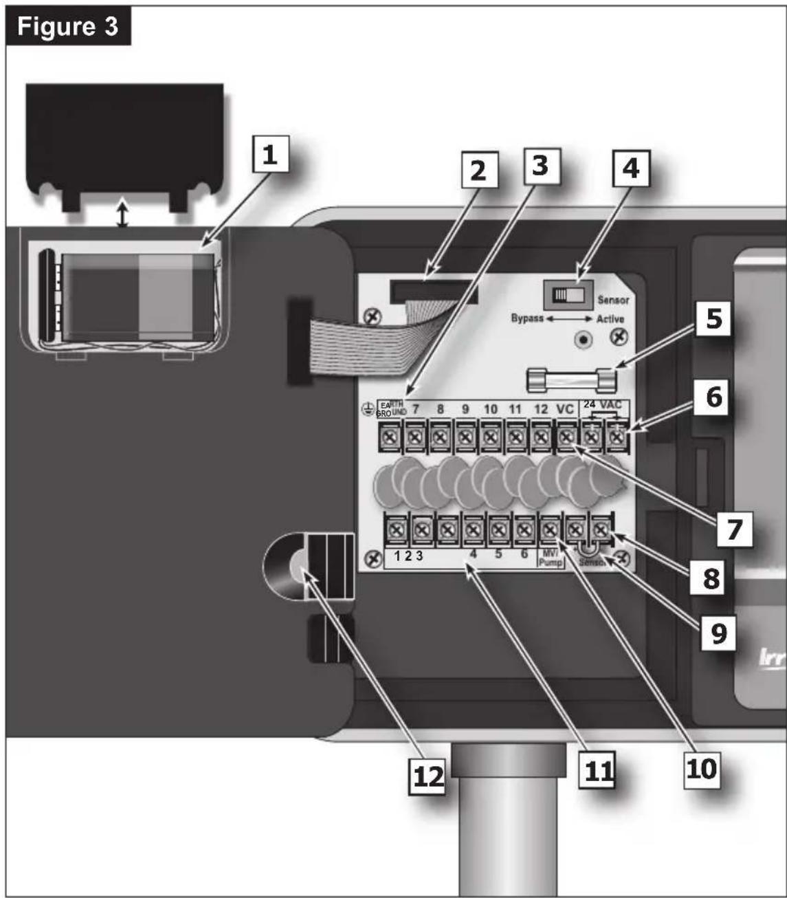
Overview: Internal Controller Components
1 - Battery Compartment
Snap-in cover provides easy access to 9V alkaline battery.
2 - Control Module Ribbon Cable
Quick disconnect cable control module from cabinet for Armchair Programming or service.
3 - Earth Ground Terminal
Wire connection terminal for earth ground conductor.
4 - Sensor Bypass Switch
Switch controls (optional) rain/freeze sensor input.
5 - Safety Fuse
2A Slow-blow fuse protects against short-circuit overload on the 24 VAC input power.
6 - Power Transformer Connection Terminals (24 VAC)
Wire connection terminals for 24 VAC plug-in transformer and power connection point for (optional) wireless rain or rain/freeze sensor.
7 - Valve Common Terminal (VC)
Wire connection terminal for the valve (field) common wire.
8 - Rain Sensor Terminals (Sensor)
Wire connection terminals for (optional) Irritrol RainSensor™ model RS500, RS1000, or RFS1000.
9 - Sensor Terminal Jumper
Sensor terminal jumper wire (removed only when a rain or rain/freeze sensor is connected).
10 - Master Valve/Pump Terminal (MV/Pump)
Wire connection terminal for (optional) master valve or pump start relay.
11 - Valve Station Terminals
Valve connection terminals – one terminal for each valve. (Terminal layout varies by model – 12-station model shown.)
12 - Handheld Remote Control Plug-in Port
Modular connector port required for the Irritrol handheld remote control system models R-100-KIT or for CLIMATE LOGIC weather sensing system.
Installation Procedures
Installing the Controller Cabinet
Select a sheltered location for the indoor model Rain Dial-R such as a garage or service room, preferably within 5' (1.5m) of a grounded electrical outlet. For outdoor controllers, choose a location that protects against direct exposure to sun and contact with irrigation spray, and is at least 5' (1.5m) away from any motorized equipment.
- Drive the provided stainless steel screw into a wall stud at approximately eye level, leaving 1/4" (6.4mm) of the screw shaft exposed.
Note: Use screw anchors when installing on drywall or masonry.
-
Hang the controller on the screw using the keyhole-shaped slot.
-
To secure the controller, drive one or two screws through the lower mounting holes.
Note: The lower mounting holes in the Outdoor cabinet have a thin veneer that is easily pierced when installing the mounting screw during installation.
Connecting the Valve Control Wiring
For best results, use connection wire cable specifically designed for automatic irrigation systems. Use 18-AWG wire for connections up to 800' from the controller, or heavier 14-AWG (2.0mm2) wire for connections up to 2000'. A separate wire for each valve (and relay) connection and at least one common (return) wire is required.
Note: If control wire conduit is required, install it at this time. For conduit installation, use the 3/4" (19mm) access hole in the indoor cabinet, or the threaded 1.25" NPT opening in the outdoor cabinet.
- Route the control wire from the controller location to the valve(s).
- Attach a separate control wire to either lead of each valve solenoid.
- To provide a common (return) wire, attach the remaining lead of each valve solenoid to a single wire.
Note: To prevent corrosion and a possible short circuit, use waterproof wire connectors on all external wire splices.
For reference at the controller, note the wire color used for each valve connection and its corresponding watering zone. - Route the cable through the largest opening in the base of the controller cabinet or through conduit if installed. Remove the cable jacket to expose about 8" of wires. Carefully remove 3/8" of insulation from the end of each wire to be connected.
- Secure each valve wire to numbered terminal in the preferred
operating sequence order.
- Connect the common wire to the terminal labeled "VC."
- If applicable, connect one leg of the master valve or pump start relay control wire to the terminal labeled "MV/PUMP", and the remaining leg to the valve common wire.
Note: The controller does not supply power to operate a pump. The pump start relay must have a nominal coil voltage of 24 VAC, rated at 0.375A maximum.

Connecting a Rain Sensor (optional)
The Rain Dial-R is designed to work in conjunction with Irritrol Rain Sensor models RS500, RS1000 or Rain/Freeze sensor RFS1000 to restrict watering when moisture and/or temperature limits are met.
Note: If connecting an alternate make of rain sensor, ensure it provides normally-closed switch circuit operation.
IMPORTANT: If a rain sensor is not installed, the sensor terminal jumper wire must remain in place, and the sensor switch must remain in the Bypass position. If either of these conditions are not met, automatic and manual operation will be disabled.
- Insert the sensor cable through the bottom of the cabinet.
- Loosen the Sensor terminals and remove the jumper wire.
- Refer to the installation instructions provided with the Rain Sensor and connect wires accordingly.
- Place the Sensor switch in the Active position.
Note: When the Rain Sensor is active, all watering operations will be terminated and SEn (Sensor) will be displayed (in the current time dial position).


Connecting a Remote Control Unit (optional)
The Rain Dial-R controller is remote-ready and is compatible with the Irritrol Handheld Remote Control model: R-100-KIT. Refer to the user guide provided with the remote kit for complete information.
As shown in the illustration below, the R-100-KIT receiver assembly simply plugs into the receptacle provided in the back of the Rain Dial-R control module.
Note: Irritrol's CLIMATE LOGIC weather sensing system's receiver module plugs in the same way.

Connecting an Earth Ground Device
Note: In order for the electrical surge components built into your Rain Dial-R to function properly, the controller must be connected to an earth ground device, such as a copper-clad ground rod or metal water pipe, using solid copper wire. This connection is especially important when the controller is installed in a lightning-prone area.
-
Connect a 12–16 AWG (2mm2–1.3mm2) solid-copper wire to the ground device and route into the controller through an access opening in the base of the cabinet.
-
Secure the ground wire to the terminal labeled "Earth Ground."

Connecting the Power Source
Connecting the Power Supply - Indoor Models
Indoor models ship prewired with a power cord ready to be plugged into a standard wall power socket.
Note: To immediately test-run the Rain Dial-R irrigation control system, refer to the "Controller Station Test Feature" on page 8.

Connecting the Power Source - Outdoor Models
Warning: All electrical components and connection methods must comply with all applicable national and local electrical codes including installation by qualified personnel. These codes may require a junction box installed on controller's 1/2" (13mm) NPT nipple and a means in the fixed wiring of disconnecting AC power having a contact separation of at least 0.120" (3mm) in the line and neutral poles. The connection wire must have insulation rated @ 105°C min.
The controller must be connected to a grounded power source. Do not connect to one phase of a 3-phase power supply used by a pump or other electrical equipment.
Prior to connecting controller wiring, verify that power has been turned off at the source by using an AC volt meter.
Steps
- Install a 1/2" (13mm) NPT conduit body to the transformer threaded fitting. From the conduit body, install electrical conduit routing to the AC power source (per electrical code).
- Pull 14 AWG through the conduit into the conduit body.
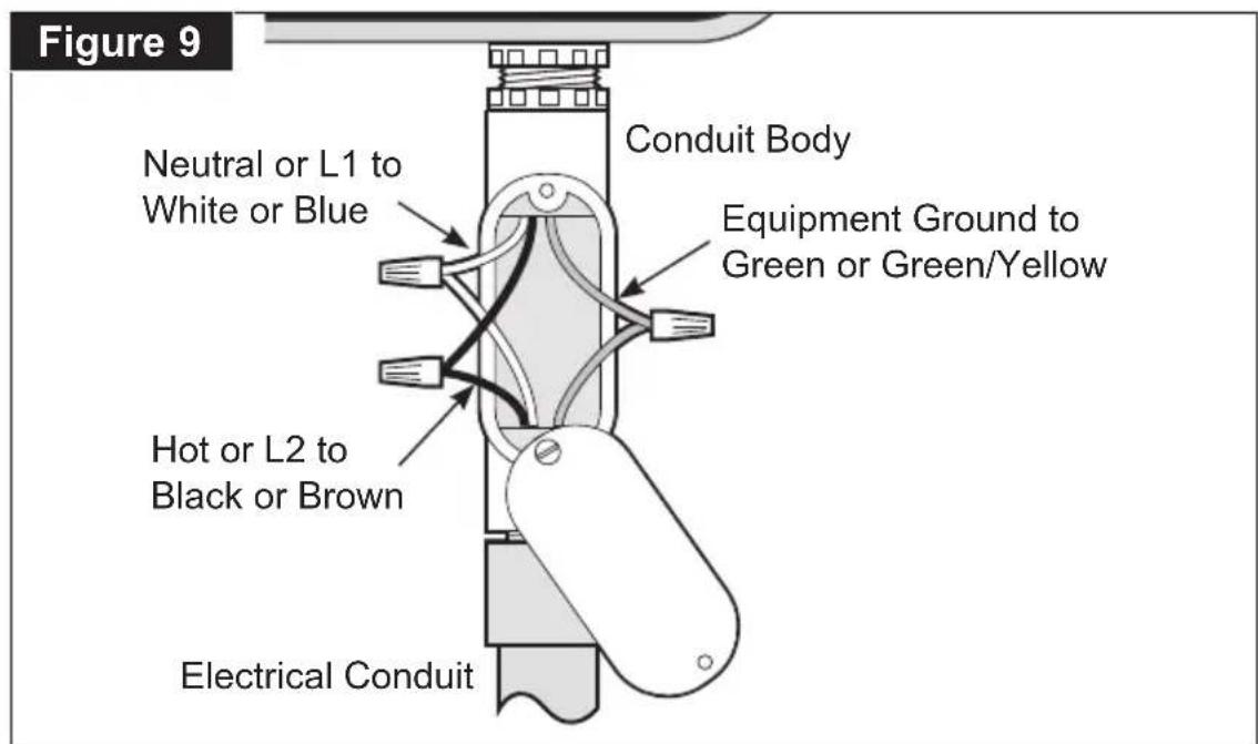
- Using twist-on wire connectors, attach the mating wires as shown in Figure 9.
-
Close and secure the conduit body cover.
-
Apply power to the controller and check controller operation. If the controller is not operating, disconnect the power at the source and have a qualified electrician check for possible short circuit.
Caution: For maximum protection of the controller electronic components when installed outdoors, always keep the cabinet cover closed and locked whenever possible. Store the cabinet keys in a safe, convenient location.

Controller Station Test Feature
The controller Station Test feature enables you to quickly check for proper valve station operation after initial installation or service. The test cycle enables all valve stations to operate in sequence for a temporary run time, adjustable from 1–10 minutes.
-
Place the Function switch in the Set Programs or Run position.
-
Turn the Dial to the Skip Days - Special Functions position.
-
Press the Manual button (one time) to select the Test Run display as shown at right.

-
A 2-minute test run time is set by default. To adjust the run time from 1–10 minutes, press the +r b
-
Press the Semi-Auto button to start the watering cycle (station 1 will turn on).
-
Turn the Dial to the Current Time position. The display will indicate the current clock time (initially 12:00 PM) and station 1.
-
To manually advance through the station operating sequence, press the Manual button.
Getting the Most From Your Controller
What is an Automatic Program Watering Cycle?
An automatic watering Program begins at its earliest assigned start time on a scheduled watering day. The lowest valve station number assigned to the Program, turns on and operates the sprinklers for the specified run time duration. When finished, the next valve station in numeric order (with an assigned run time in the Program) begins operation. The Program Watering Cycle continues until all valve stations with an assigned run time in the Program have operated.
Why three programs?
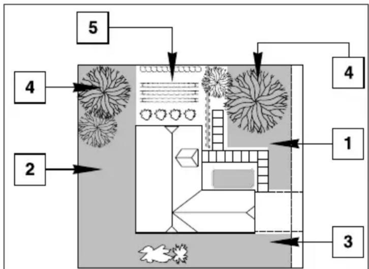
A typical residential landscape includes various sections of lawn, shrubs, trees and ground cover, all of which require watering on different schedules for optimum plant health and conservation. To accommodate this, the Rain Dial-R provides three independent watering Programs: A, B and C.
flowchart
graph TD
    1 --> 2
    2 --> 4
    4 --> 5
    5 --> 3
    3 --> 1
    1 --> 4
    style 1 fill:#f9f,stroke:#333
    style 2 fill:#ccf,stroke:#333
    style 3 fill:#cfc,stroke:#333
    style 4 fill:#fcc,stroke:#333
    style 5 fill:#cff,stroke:#333
Valve locations
The example below shows how multiple Programs can be used to easily accomplish this:
| Program Start Time | Valve # | Location Run Time | Schedule |
| A (#1) 5:00 AM | 1 Front Lawn 15 min. Odd | ||
| 2 Back yard 15 min. Odd | |||
| 3 Side Yard 10 min. Odd | |||
| B (#1) 3:00 PM | 4 Trees (drip) | 2 hrs. | Mon |
| C (#1) 4:00 PM | 5 Garden | 5 min. | Skip Days (1) |
| (#1) 7:30 PM | 5 Garden | 5 min. | Skip Days (1) |
Avoid unexpected start times
It is possible to set a second start time that begins before the watering cycle from the first start time has finished. When this happens, the start of the second cycle is delayed until the first is complete; so the start time may not occur when you expect it. In addition, increasing run time with the water budget feature may cause an overlap that delays the next scheduled start time.
Avoid watering on a non-watering day
A watering cycle that continues beyond Midnight will run to completion regardless if the next day is scheduled for watering.
Avoid excessive watering
By default, Programs A, B and C can be scheduled to run concurrently (overlap). This feature can be restricted by selecting the Program Stacking option (see page 13). Start times entered for any program will begin automatically when that time occurs. Using multiple programs enables valve stations to water on different schedules or to provide additional watering if one program is not enough. If you need extra water, use more than one start time and/or use the Water Budget feature to increase the valve station run time.
Avoid Creating a low water pressure condition
Start times assigned to different programs are independent. If you set identical or overlapping start times, more than one valve station can run at the same time. The total flow may exceed the available water supply. To avoid this situation, allow more time between start times to reduce the number of valves running at one time, and make sure that multiple Programs do not have the same start times.
Establishing new lawns
Having short, multiple watering cycles each day is especially useful when establishing a new lawn.
Help with electrical problems
The Rain Dial-R will display the station number and the word "FUS" if a short-circuit on a valve station is detected. The detected station will be bypassed, allowing the remaining operable stations to run in the Program watering cycle.
What the Display Indicates
The following examples represent the display information provided to assist you within the various programming, setup and operating modes.
Programming Mode (Function – Set Programs)
- Current Time - Displays the current time of day.
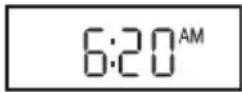
- Valve Run Times - Displays the run time set for a selected valve number. Will indicate 01–59 minutes, 1.0–5.9 hours or Off.
- Start Times - Displays start time(s) assigned to the selected Program.

- Today - Displays the current day within a Weekday schedule, e.g. Su, Mo, etc., or Skip Days schedule day (1–31).

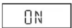
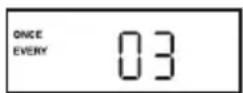
- Schedule - Displays ON or OFF for each day in a Weekday schedule. When using an Odd/Even schedule, Odd, Even or OFF will be displayed for each station. When using a Skip Days schedule, Once Every (01–31) will be displayed.

- Special Functions (Dial – Special Functions)
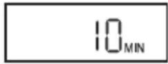
- Station Test Cycle - All active station numbers will be shown at the top of the display. T:01–10 indicates minutes of run time selected for test cycle.

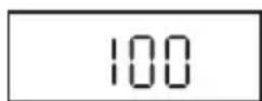
- Water Budget (Per Program) - Displays the current Water Budget % or OFF. If a Monthly Water Budget is in use, (---) will be shown.
- Clear Program Memory - CLr indicates the Clear Program Memory function is selected.

- Well Recovery Time - Indicates the delay time (00–59 seconds, 1–59 minutes or 1–2 hours) set to occur between stations in a watering cycle.
- Pump Operation during Station Delay - Indicates pump operation is set to On or Off during a station delay period.
- Program Stacking/Overlap - Indicates Program Stacking (1:On) or
Overlap
(3:On)

- Odd/Even Schedule - Indicates Odd or Evn schedule selected.
- Calender month - Displays the current month.
- Calender month/day - Displays the current month and day.
• Year - Displays the current year. - Rain Delay - Indicates number of days (0–9) set to delay automatic operation.
- Monthly Water Budget - Indicates Water Budget status (On/Off) per month (1–12) and % factor (01–200 or Off) assigned to each month. (Month, day and year may also be set at this time.)
W:02
P:OF
1:0n
Odd
JA
J:30
08
rd3
1 2 3 4 5 6 7 8 9 10 11 12 ON ON
1 2 3 4 5 6 7 8 9 10 11 12 85
Run Mode (Function - Run)
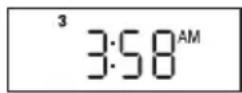
- Automatic Mode (Dial – Current Time) - Active valve number and current time are shown. (Dial – Active valve number)- active valve number, current Program and remaining run time.
Note: If Water Budget is active, the adjusted run time will be shown. - Manual Mode - (Dial – Active valve number)-Valve number, M: and remaining run time are shown.
- Rain Delay - OF (Off) and the number of days until watering resumes alternates with the current time.
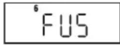
- Diagnostic Circuit Breaker - "FUS" (Fuse) and the bypassed valve number(s) will alternate with the current time.


Basic Programming Procedures
Setting the Current Time and Day
- Place the Function switch in the Set Programs (center) position.
- Turn the Dial to the Current Time position.
- Press the 📋 button to set the current time (note AM/PM).
Note: When using the +r button, press and release to adjust in steps, or press and hold to scroll.
- Turn the Dial to the Today position.
- Press the ☐ button to select the current day (abbreviation).
Note: If Odd/Even schedule or Monthly Water Budget is used, the current day of the week is preset and cannot be changed.
- Return the Dial to the Current Time position.
- Return the Function switch to the Run position.
Note: The flashing colon (:) indicates AC power is present.
If the colon is not flashing, the controller is operating on battery power only.
Setting the Valve Run Time Duration
Each valve station can have an individual run time assignment in each Program. Run time can be set for 1–59 minutes (in 1-minute increments) or 1–5.9 hours (in 1/10-hour increments).
- Place the Function switch in the Set Programs (center) position.
- Select Program A, B or C.
- Turn the Dial to select the valve number.
- Press the ☐ button to set the valve run time duration.
- Repeat steps 3 and 4 for all valves to be assigned to the selected Program.
- Repeat steps 2–5 for each Program as needed.
- When finished, return the Dial to the Current Time position.
- Place the Function switch in the Run position.
Setting the Program Cycle Start Time(s)
Each Program can have three separate start times. For mature landscapes, one start time per Program is generally sufficient. When establishing a new lawn, using two or three start times with short valve run times can provide the additional irrigation required for grow-in, at a reduced rate to help prevent runoff and erosion.
- Place the Function switch in the Set Programs position.
- Select Program A, B or C.
- Turn the Dial to select Start Time 1 (2 or 3).
- Press the ⏻ button to set the start time (note AM/PM).
Note: To remove a start time, select Off, displayed between 11:59–12:00 and 5:59–6:00 (AM and PM).
- Repeat steps 3 and 4 to set additional start times for this Program.
- Repeat steps 2–5 for each Program as needed.
- When finished, return the Dial to the Current Time position.
- Return the Function switch to the Run position.
Setting the Program Watering Day Schedule
Watering days can be scheduled for each Program using one of the following methods:
- Weekdays - Schedules watering for specific days of the week.
- Skip Day - Schedules watering days by interval frequency; e.g., every day (01), every-other-day (02) etc.
- Odd/Even Date - Schedules watering days based on Odd- or Even-numbered calendar days.
To set a Weekdays Schedule:
- Place the Function switch in the Set Programs position.
- Select Program A, B or C.
- Turn the Dial to the desired weekday position.
- Press the button to select the day (On), or the button remove the day (Off) from the watering day schedule.
- Repeat steps 3 and 4 to schedule additional weekdays as needed.
- Repeat steps 2–5 for each Program as needed.
-
When finished, return the Dial to the Current Time position.
-
Return the Function switch to the Run position.
Note: Each Program can have a Skip Days or an Odd/Even Date watering schedule, but not both. One schedule must be turned off to enable the alternate schedule to be selected.
To Set a Skip Day Schedule:
- Place the Function switch in the Set Programs position.
- Select Program A, B or C.
- Turn the Dial to the Skip Days/Special Functions position.
- Press the ⊕ / ⊖ buttons to select the Skip Day interval (01–31) days.
Note: To turn Off a Skip Day schedule, press the button to display OFF.
- Turn the Dial to the Today position.
- Press the /buttons to select the current day within the Skip Day interval schedule.
Note: For example, if you have selected a 3-day schedule, and prefer to have watering start today, select 03. To water tomorrow, select 02. To watering in three days, select 01.
- Repeat steps 2–6 for each Program as needed.
- When finished, return the Dial to the Current Time position.
- Return the Function switch to the Run position.
To Set an Odd/Even Date Schedule:
- Place the Function switch in the Set Programs position.
- Select Program A, B or C.
- Turn the Dial to the Skip Days/Special Functions position.
- Press the Manual button (seven times) to display dashes (---).
- Press the ⚠ button to select Odd, or the ⏰ button to select Even (EVn).
Note: To turn Off an Odd/Even Date schedule, press the + button to display dashes (---).

-
Press the Manual button (one time) to select the calendar Month – January (JA) will be displayed.
-
Press the + buttons to adjust the month setting.
JA - January
AP - April
JL - July
OC - October
Fe - February
My - May,
AU - August
nO - November
MR - March
JN - June,
SE - September,
DE - December.
-
Press the Manual button (one time) to select the Day setting.
-
Press the + buttons to select the current calendar day.
Example: September 17th would be displayed as S:17.
-
Press the Manual button (one time) to select the Year setting.
-
Press the ⚠ b…ons to select the year (09 = 2009).
-
When finished, return the Dial to the Current Time position.
-
Repeat steps 2–10 for each Program as needed.
-
Return the Function switch to the Run position.
Note: When an Odd/Even schedule is used, confirm that the current day of the week is correctly set by turning the Dial to the Today position. If the day of the week is incorrect, adjust the month, day and year settings to properly synchronize the controller.
Also note that when using an Odd/Even schedule, watering never occurs on the 31st of any month or February 29th of a leap year.
Day Exclusion Feature
When using a Skip Days and Odd/Even date watering schedule, watering will not occur on the same days from week to week. To restrict watering on specific weekdays; e.g., for scheduled mowing or maintenance, use the Day Exclusion feature as follows:
- Place the Function switch in the Set Programs position.
- Select Program A, B or C.
- Turn the Dial to the Day to be excluded.
- Press the - button display OFF.
- Repeat steps 3 and 4 to exclude additional days.
- When finished, return the Dial to the Current Time position.
- Return the Function switch to the Run position.
This completes the basic programming requirements for automatic operation.
Special Functions
Rain Delay
The Rain Delay feature (for use when a weather sensor is not installed) enables automatic watering operation to be suspended for a period of 1 to 9 days; then resume watering automatically as scheduled.
- Place the Function switch in the Set Programs position.
- Turn the Dial to the Skip Days - Special Functions position.
- Press the Manual button (repeatedly) to display rd0 (Rain Delay = 0 days).
- Press the /buttons to select a Rain Delay period of 1 to 9 days.
- Return the Dial to the Current Time position.
- Return the Function switch to the Run position.
Note: When the Rain Delay function is active, the display will alternately indicate the current time of day and the number of days remaining until automatic operation resumes. To cancel Rain Delay at any time, decrease Rain Delay setting to 0 days.
Water Budget
The Water Budget feature enables the run time of all stations, assigned to a specific Program, to be simultaneously adjusted up or down by percentage. From the baseline of 100%, run times can be reduced to 0% (Off) or increased up to 200%.
To help prevent runoff when selecting a Water Budget value above 100%, the adjusted run time is automatically cut in half, and the watering cycle is run twice. For example, increasing the Water Budget to 160% would first increase a 10-minute station run time to 16 minutes. However, the station will run for 8 minutes in two consecutive watering cycles.
All zone run times are retained in the timer memory and returned to their set value when the season adjust is reset to 100%. The only time a station run time will appear changed is during operation.
For additional control, a Water Budget factor can be assigned universally to a Program, or applied to a Program by specific months of the year – when Water Budgeting by seasonal demand is preferred.
Note: Each Program is limited to one Water Budget method at a time. Applying a Water Budget by monthly demand will override a basic Water
Budget adjustment value. Conversely, to apply a basic Water Budget, all months must be set at 100%.
To Apply a Basic Water Budget:
- Turn the Dial to the Skip Days - Special Functions position.
- Select Program A, B or C.
- Place the Function switch in the Set Programs position.
- Press the Manual button (twice) to display 100 (%).
- Press the output to adjust the % factor (10% increments).
Note: Decreasing the Water Budget value beyond 10% to "OFF" prevents the Program from running automatically.
- Return the Dial to the Current Time position.
- Return the Function switch to the Run position.
To Apply a Monthly Water Budget:
Note: Applying a monthly Water Budget requires the current date to be set. If an Odd/Even watering schedule has been assigned, the current date was established during the procedure. Steps 1–11 in the following procedure establishes the current date. To bypass this portion of the procedure, begin at step 12.
- Turn the Dial to the Skip Days - Special Functions position.
- Select Program A, B or C.
- Place the Function switch in the Set Programs position.
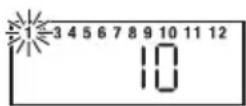
- Press the Manual button repeatedly to select the Monthly Water Budget display as shown at right.
- Press the Button to select ON.
- Press the Manual button one time to select the calendar Month setting. January (JA) will be displayed.
- Press the + or - button to select the current month abbreviation:
JA - January
AP - April
JL - July
OC - October
Fe - February
My - May,
AU - August
nO - November
MR - March
JN - June,
SE - September,
DE - December.
- With the month selected, press the Manual button one time to select the Day setting.
- Use the + / - buttons to select the current calendar day.


For example, April 4 would be displayed as A:04.
- Press the Manual button one time to select the Year setting.
- Press the ⊕ / ⊖ buttons to select the current year (09 = 2009).
- Press the Manual button (as needed) to select the Monthly Water Budget display. 1 (January) is selected with its current Water Budget value (100% by default).
- To change the month selection, press the Manual button.
- Press the ⭕ / ⭕ buttons to adjust the % factor in 1% increments down or up (Off or 10%-200%).
- Repeat steps 13 and 14 to set additional months.
- When finished, return the Dial to the Current Time position.
- Return the Function switch to the Run position.

Stack/Overlap
The Stack/Overlap option determines how the controller will manage concurrently scheduled programs or manually started valve stations. By default, the Overlap option is selected, enabling simultaneous operation of up to three Programs or manual valve stations. Selecting the Stack option limits operation to either one automatic Program or manual valve station.
⚠️ Important:
- The Stack option prevents a scheduled Program or manually operated valve station from operating until any current operation has been completed or canceled. At midnight, any remaining scheduled Programs stacked in queue will be canceled.
-
Selecting the Overlap option can cause the electrical and/or hydraulic capacity of your irrigation system to be exceeded. Always plan your watering schedule carefully!
-
Turn the Dial to the Skip Days - Special Functions position.
- Place the Function switch in the Set Programs position.
- Press the Manual button repeatedly to display 3:On (three programs or stations can run concurrently).
- To select the Stack option, press the /+ut→ to choose 1:On.
- Return the Dial to the Current Time position.
- Return the Function switch to the Run position.
Station Delay
Irrigation systems that utilize a well-water source or have slow-closing valves, may require a delay period to occur between consecutive stations during a watering cycle. The Station Delay feature enables a delay period to be set from 1 second to 2 hours.
- Place the Function switch in the Set Programs position.
- Select Program A, B or C.
- Turn the Dial to the Skip Days - Special Functions position.
- Press the Manual button repeatedly to display W:00 (no delay).
- Press the /+u-ns to set the delay time: 00–59 seconds, 01–59 minutes (MIN) or 1.0–2.0 hours (HR.).
Note: Hold the button down to scroll. The display will continuously scroll from seconds to minutes to hours (:00 = no delay time).
- Return the Dial to the Current Time position.
- Return the Function switch to the Run position.
Pump Control During Station Delay
The Pump Control feature is generally used in conjunction with the Station Delay feature, enabling the pump/master valve to be turned on or off during the delay between consecutive stations in a watering cycle. For example, a system with slow-closing valves may require the pump to remain on throughout the watering cycle to assist valve closure. Alternately, a system utilizing a well-water supply source may require the pump to be off when an extended delay period between stations is required for adequate well-recovery time.
- Place the Function switch in the Set Programs position.
- Select Program A, B or C.
- Turn the Dial to the Skip Days - Special Functions position.
- Press the Manual button (repeatedly) to display P:OF (Pump Off).
- Press the +/− button to toggle between P:OF and P:On.
- Return the Dial to the Current Time position.
- Return the Function switch to the Run position.
Pump Control Option
By default, the pump control circuit is activated simultaneously with any automatic or manual valve station operation. When pump operation is not required for specific valve stations; e.g., drip irrigation, the pump control circuit can be easily disabled as needed.
Note: The Pump control option applies to the selected valve station regardless of its Program assignment.
- Place the Function switch in the Set Programs position.
- Turn the Dial to select the appropriate valve station number.
- Press the Manual button: P:On (Pump On) will be displayed.
- To disable the pump control circuit from the valve station, press the
- button to display P:OF (Pump Off).
- Repeat steps 2–4 for additional valve stations as required.
- Return the Dial to the Current Time position.
- Return the Function switch to the Run position.
Diagnostic Circuit Breaker
The prompt "FUS" and the malfunctioning valve station number will be alternately displayed with the current time. The valve station will be bypassed during the watering cycle, enabling all remaining valve stations to run as scheduled.
With the Dial set in the Current Time position, press any button to clear the "FUS" display.
⚠️ Important: Determine the cause of the malfunction and take corrective action as necessary. Clearing the display will not resolve the problem.
Fuse Replacement
Caution: The 2.0A safety fuse protects the transformer from damage due an excessive current load (short circuit) condition.
Locate and eliminate the cause of the problem before replacing the fuse. For continued protection against risk of fire, replace only with the same fuse type and rating.
- Disconnect power to the controller.
- Carefully remove the safety fuse from the terminal board (see Figure 3, page 4 for fuse location).
- Install a new 2.0A slow-blow fuse, ensuring that it is properly seated
in the retaining clip.
- Reconnect power to the controller.
Manual Operations
Semi-Automatic Program Operation
Semi-Automatic Program operation enables an automatic Program watering cycle to be started manually at any time. Once running, the manual advance feature enables you to step through the programmed station sequence.
- Place the Function switch in the Run position.
- Turn the Dial to the Current Time position.
- Place the Program switch to select A, B or C.
- Press the Semi-Auto button to start the watering cycle.
Note: Once started, the station sequence can be manually advanced by placing the Dial to Current Time and pressing the Manual button.
Note: The Manual Advance feature applies to all Automatic, Semi-automatic and Station Test watering operations for the selected Program.
Note: To terminate watering operations, place the Function switch momentarily in the OFF or Stop position.
Manual Station Operation
Manual station operation provides manual control at the individual station level and provides the following four control options:
- Station(s) can be operated for a one-time run duration without altering the station's set run time in an automatic Program.
- Operation can be limited to only one station running manually or set to allow three stations to run at the same time.
Note: Refer to "Stack/Overlap Option" on page 26 for additional information regarding manual operations.
- Works with the Manual Advance feature to move up through the station sequence.
- Place the Function switch in the Run position.
-
Turn the Dial to the Station Number to be manually operated.
-
Use the /+lutions to set a manual operation run time ranging from 1 minute to 5.9 hours.
- Press the Manual button to start the operation.
- If this is the only station to be run manually, skip step 6 and continue at step 7 below.
- To add additional stations to the manual run operation, repeat steps 2 through 4 as needed, then continue at step 7.
Note: Depending upon the Stack/Overlap setting, additional stations selected (beyond the one or three option setting) will register as OFF when entered with the Manual button. However, they will be placed (stacked) in the manual sequence to run.
- Turn the Dial to the Current Time position.
Note: Once started, the station sequence can be manually advanced by pressing the Manual button.
Note: To terminate manual watering operations, place the Function switch momentarily in the OFF or Stop position.
Clear Program Memory
The Clear Program Memory feature enables you to safely clear the automatic watering program settings defined for a specific Program without affecting any remaining Program information. The memory erase function applies only to the specified Program, leaving the remaining Programs intact.
⚠️ Important: The “Clear Program” function completely erases all user-defined programming information from the selected Program including: start times, run times, and watering day schedule.
Note: To reset the controller (all Programs) to factory default settings, refer to "Restore Rain Dial-R to Factory Default Settings" on page 35.
- Place the Function switch in the Set Programs position.
- Place the Program switch to select A, B or C.
- Turn the Dial to the Skip Days - Special Functions position.
- Press the Manual button repeatedly to display CLr (Clear).
-
Press the ☐ button one time. The display will show the prompt: CL? (Clear?).
-
To complete the process, press the button again to display the prompt "End".
- Return the Dial to the Current Time position.
- Return the Function switch to the Run position.
Restore Factory Default Settings
The Rain Dial-R factory default settings for automatic program operation are as follows:
Current Time: 12:00 AM.
Current Day: Sunday.
Current Date: January 1, 2008.
Program A: Weekday watering schedule with all days active.
One start time at 7:00 AM.
10-minute run time on all valve stations.
Program B and C: No watering days, station run times or start times.
Skip Days and Odd/Even day schedule: OFF - all Programs.
Excluded days in Skip Days or Odd/Even schedule: None.
MV/Pump operation: ON - all stations.
Well Recovery period: 00 (OFF) - all Programs.
MV/Pump operation during Well Recovery: OFF - all Programs.
Water Budget: 100% - all Programs and months.
Rain Delay: 0 days.
Stack/Overlap: Overlap - 3 Programs or 3 manual stations.
To restore factory default settings:
- Turn the dial to Start Time number 3.
- Repeatedly press the Manual button.*
- After the first 7 depressions, the firmware version appears in the display.
- On the 14th depression, "CLr" appears.
- On the 15th depression, "ALL" appears.
- On the 16th depression, "OFF" begins flashing indicating erasure of all user-entered information.
- Turn the dial back to CURRENT TIME. "12:00AM" appears in the
display.
* The numerous button depressions required are to avoid inadvertent or accidental erasure.
Troubleshooting Guide
| Problem Possible Cause Correction | ||
| Display blank. No power. | Check transformer/power connections, 2A fuse, and AC power. | |
| Some valves do not operate. | Faulty or improper valve wire connections.Debris in valve. | Check and correct all valve wire connections.Inspect, clean/replace valve solenoid/plunger and diaphragm. |
| No valves operate. Function switch OFF.Faulty valve common wire connection.Sensor switch in Active position-no sensor or jumper connected.No start time set. | Set switch to Run.Check/correct valve common connection.Set switch to Bypass or install terminal jumper.Set Program start time. | |
| Watering on wrong day. | Watering day schedule set incorrectly. | Correct watering day schedule as needed. |
| Current time is wrong and flashing. | Power interruption without battery backup. | Install/replace battery, reset current time. |
| "FUS" and a station number alternates with current time. | Short or over-current on valve station. | Check/replace valve solenoid and splices. |
| Valve will not turn off (with Function Switch.in the OFF position). | Valve malfunction. Inspect | clean/replace valve solenoid/plunger and diaphragm. |
| "SEN" alternates with time of day. | Watering on hold due to sensor operation. | Normal operation for sensor. Set Sensor switch to Bypass. |
Contact Information
The troubleshooting solutions are provided to help resolve problems that may arise during setup and/or operation of the Rain Dial-R controller.
If the problem is not listed or cannot be resolved with the provided solutions, contact an authorized Irritrol product expert for assistance via phone or email.
U.S./Canada: Phone: 1-800-634-8873 (7:30 am–4 pm, M–F, PT)
E-mail: irrigationsupport@irritrol.com
Europe: Phone: +39-076540191
E-mail: intlirrigationsupport@irritrol.com
Australia: Phone: +61 8 8300 3633
E-mail: intlirrigationsupport@irritrol.com
Specifications
Input Power
• Outdoor Model: 120 VAC 60 Hz, 30 VA (Domestic)
230/240 VAC, 50 Hz, 30VA
(International)
- Indoor Model: 24 VAC, 60 Hz, 30 VA (Domestic)
(from plug-in transformer) 24 VAC, 50 Hz, 30 VA
(International and Australian)
All Models:
• Station Output: 24 VAC at 0.5A, 1.0A (maximum total)
• Master Valve/Pump Start Relay Output: 24 VAC at 0.375A
• 2.0A Slow-blow Fuse
- Battery Back-up (time, day and date)
- Operating temperature range: 32^ to 140^ (0°C to 60°C)
Caution: The Rain Dial is designed to operate 24 VAC valve solenoids rated at 0.25A (6 VA). Total current load during operation must not exceed 1.0A. A maximum of two solenoids per station terminal may be used if the total station load does not exceed 0.5A. No more than three solenoids (plus MV/Pump circuit) should operate concurrently. In irrigation systems where multiple controllers are used, each controller must utilize a separate valve common circuit.
FCC Rules
This equipment has been tested and found to comply with the limits for a Class B digital device, pursuant to Subpart J of Part 15 of the FCC Rules. These limits are designed to provide reasonable protection against harmful interference in a residential installation. This equipment generates, uses and can radiate radio frequency energy and, if not installed and used in accordance with the instructions, may cause harmful interference to radio communications. However, there is no guarantee that interference will not occur in a particular installation. If this equipment does harmful interference to radio or television reception, which can be determined by turning the equipment off and on, the user is encouraged to try to correct the interference by one or more of the following measures:
- Reorient or relocate the receiving antenna.
- Increase the separation between the equipment and receiver.
-
Connect the equipment into an outlet on a circuit different from that to which the receiver is connected.
-
Consult the dealer or an experienced radio/TV technician for help.
The user may find the following booklet prepared by the Federal Communications Commission helpful:
"How To Identify and Resolve Radio-TV Interference Problems." This booklet is available from the U.S. Government Printing Office, Washington, DC 20402, stock # 004-000-00345-4.
International: This is a CISPR 22 Class B product.

WARNING: Cancer and Reproductive harm – www.P65Warning.ca.go. For more information, please visit www.toro.com/CAProp65.
Patents: www.ttcopats.com
Notes
Irritrol®
- Irrigation System Controller
- User's Guide
- Table of Contents
- Getting to Know your Rain Dial-R Controller 2
- Getting Started....4
- Installation Procedures....10
- Getting the Most From Your Rain Dial-R Controller ....18
- What the Display Indicates....20
- Basic Programming Procedures....23
- Special Functions ......27
- Pump Control Option....31
- Diagnostic Circuit Breaker 31
- Fuse Replacement....31
- Manual Operations....32
- Clear Program Memory 33
- Restore Factory Default Settings....34
- Troubleshooting Guide....35
- Contact Information......36
- Specifications....36
- FCC Rules ......37
- Getting to Know your Rain Dial-R Controller
- Getting Started
- Battery Installation & Armchair Programming
- Installing the Battery
- Overview: Control Module Interface
- - Program Switch
- - LCD Display
- - Plus and Minus Buttons
- - Dial
- - Manual Button
- - Function Switch
- - Semi-Auto Start Button
- Overview: Internal Controller Components
- - Battery Compartment
- - Control Module Ribbon Cable
- - Earth Ground Terminal
- - Sensor Bypass Switch
- - Safety Fuse
- - Power Transformer Connection Terminals (24 VAC)
- - Valve Common Terminal (VC)
- - Rain Sensor Terminals (Sensor)
- - Sensor Terminal Jumper
- - Master Valve/Pump Terminal (MV/Pump)
- - Valve Station Terminals
- - Handheld Remote Control Plug-in Port
- Installation Procedures
- Installing the Controller Cabinet
- Connecting the Valve Control Wiring
- Connecting a Rain Sensor (optional)
- Connecting a Remote Control Unit (optional)
- Connecting an Earth Ground Device
- Connecting the Power Source
- Connecting the Power Supply - Indoor Models
- Connecting the Power Source - Outdoor Models
- Steps
- Controller Station Test Feature
- Getting the Most From Your Controller
- What is an Automatic Program Watering Cycle?
- Why three programs?
- Avoid unexpected start times
- Avoid watering on a non-watering day
- Avoid excessive watering
- Avoid Creating a low water pressure condition
- Establishing new lawns
- Help with electrical problems
- What the Display Indicates
- Programming Mode (Function – Set Programs)
- Run Mode (Function - Run)
- Basic Programming Procedures
- Setting the Current Time and Day
- Setting the Valve Run Time Duration
- Setting the Program Cycle Start Time(s)
- Setting the Program Watering Day Schedule
- To set a Weekdays Schedule:
- To Set a Skip Day Schedule:
- To Set an Odd/Even Date Schedule:
- Day Exclusion Feature
- Special Functions
- Rain Delay
- Water Budget
- To Apply a Basic Water Budget:
- To Apply a Monthly Water Budget:
- Stack/Overlap
- ⚠️ Important:
- Station Delay
- Pump Control During Station Delay
- Pump Control Option
- Diagnostic Circuit Breaker
- Fuse Replacement
- Manual Operations
- Semi-Automatic Program Operation
- Manual Station Operation
- Clear Program Memory
- Restore Factory Default Settings
- To restore factory default settings:
- Contact Information
- Specifications
- Input Power
- All Models:
- FCC Rules
- Notes
Brand : Irritrol
Model : RD900-MOD-R
Category : Remote control