ECI9455S - Range hood ELECTROLUX - Free user manual and instructions
Find the device manual for free ECI9455S ELECTROLUX in PDF.


User questions about ECI9455S ELECTROLUX
0 question about this device. Answer the ones you know or ask your own.
Ask a new question about this device
Download the instructions for your Range hood in PDF format for free! Find your manual ECI9455S - ELECTROLUX and take your electronic device back in hand. On this page are published all the documents necessary for the use of your device. ECI9455S by ELECTROLUX.
USER MANUAL ECI9455S ELECTROLUX
WE'RE THINKING OF YOU
Thank you for purchasing an Electrolux appliance. You've chosen a product that brings with it decades of professional experience and innovation. Ingenious and stylish, it has been designed with you in mind. So whenever you use it, you can be safe in the knowledge that you'll get great results every time. Welcome to Electrolux.
BEFORE USING YOUR APPLIANCE
Before you use the rangehood, we recommend that you read through the whole user manual which provides the description of the rangehood and its functions. To avoid the risks that are always present when you use an electrical appliance, it is important that the rangehood is installed correctly and that you read the safety instructions carefully to avoid misuse and hazards.
For future reference, please store this booklet in a safe place.
CONDITIONS OF USE
This appliance is intended to be used in household and similar applications such as
• Staff kitchen areas in shops, offices and other working environments
- Farm houses
- By clients in hotels, motels and other residential type environments
• Bed and breakfast type environments
BEFORE YOU CALL
Please ensure you read the instruction manual fully before you call for service, or a full service fee could be applicable.
RECORD MODEL AND SERIAL NUMBER HERE:
Model:
Serial NO:
CONTENTS
3 Safety information
4 Product description
5 Dimensions
6 Rangehood installation
9 Using the rangehood
10 Maintenance and cleaning
11 Troubleshooting
12 Consumer Care Center
LEGEND
! WARNING!
This symbol indicates information concerning your personal safety
! CAUTIONS!
This symbol indicates information on how to avoid damaging the rangehood.
i IMPORTANT!
This symbol indicates tips and information about use of the rangehood.
ENVIRONMENT!
This symbol indicates tips and information about economical and ecological use of the rangehood.
RoHS
If at any time in future you need to dispose of this product please do Not dispose of this product with household waste, please send this product to collecting points where available
This product is RoHS compliant.
SAFETY INFORMATION
This manual explains the proper use of your new Electrolux canopy rangehood. Please read this manual carefully before using the product. This manual should be kept in a safe place for handy reference.
This rangehood is a domestic appliance which has been manufactured and tested to comply with International Standard IEC 60335.2.31.
Read the following carefully to avoid damage or injury.

This symbol indicates never to do this
This symbol indicates always do this

WARNING!
Follow these instructions carefully to avoid an electric shock or fire.
| 2 | Young children should be supervised to ensure they do not play with the rangehood. |
| 3 | This appliance is not intended for use by persons (including children) with reduced physical, sensory or mental capabilities, or lack of experience and knowledge, unless they have been given supervision or instruction concerning the use of the appliance by a person responsible for their safety. |
| 2 | Ensure the rangehood is switched off before carrying out maintenance, to avoid any possibility of electric shock. |
| 5 | Never carry out flambe cooking under the rangehood. |
| 5 | This rangehood is not recommended for barbecues. |
| 5 | This rangehood cannot be installed for external use. |
| 2 | Grease filters must be removed every four weeks (maximum) for cleaning to reduce the risk of fire. |
| 5 | The exhaust from the rangehood must not be discharged into any heating flue, which may carry combustion products from other sources.(Fig.1) |
| 5 | The exhaust air must not be discharged into a wall cavity, unless the cavity if designed for the purpose. |
| 2 | There must be adequate ventilation of the room when the rangehood is used at the same time as appliances burning gas or other fuels. |
| 2 | Always cover lit gas burners with pots or pans when rangehood is in use. |
| 2 | Always switch off gas burners before you remove pots or pans. |
| 5 | Do not leave lit gas burners exposed due to the risk of fire.(Fig.2) |
Electrical connection
Check that the mains voltage matches with the voltage on the data plate inside the rangehood. Check that the installation complies with standards of local building, gas and electrical authorities. Before connecting to the mains supply ensure that the mains voltage corresponds to the voltage on the rating plate inside the rangehood. If the supply cord is damaged, it must be replaced by the manufacturer or its service agent or similarly qualified person in order to avoid a hazard.
Safety warnings For the installer
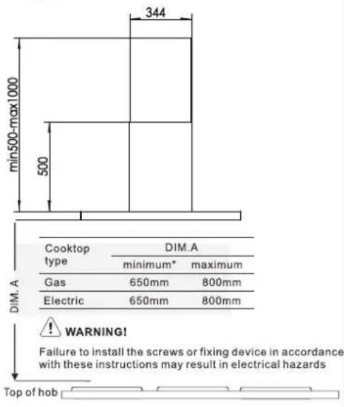
When installing the rangehood, make sure you adhere to the minimum and maximum distances from the rangehood base to the hob surface (as per table on page 6).
Exhaust flue installation: The following rules must be strictly followed to obtain optimal air extraction.
- Keep exhaust flue short and straight
• Do not reduce the size or restrict exhaust flue. - Keep bends in the exhaust flue to a minimum.
- When using flexible flue always install duct with helix pulled taut to minimise pressure loss.
- Failure to observe these basic instructions will drastically reduce the performance and increase the noise levels of the range hood.
Exhaust air must not be discharged into a wall cavity, unless the cavity is designed for the purpose. The exhaust from the cooker hood must not be discharged into any heating flue, which may carry combustion products from other sources.
NOTE: Some installations may require the telescopic exhaust cover to be cut to length. Cut with sharp tin snips or a fine-tooth hack saw blade, taking are not to distort or dent the exhaust cover.
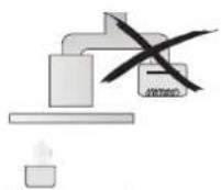
Fig. 1
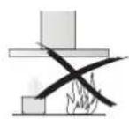
Fig. 2
DIMENSIONS

text_image
344 294 min500-max1000 500 604 898PRODUCT DESCRIPTION
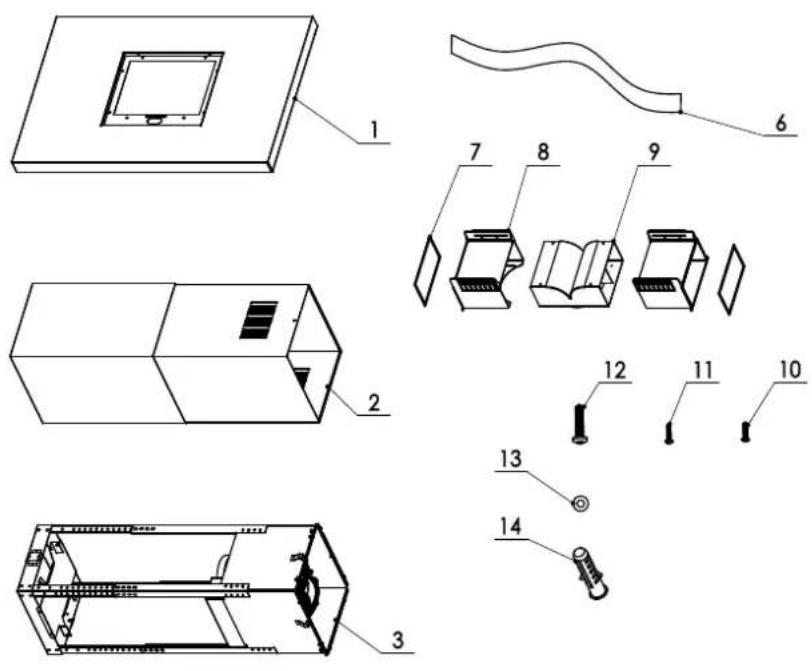
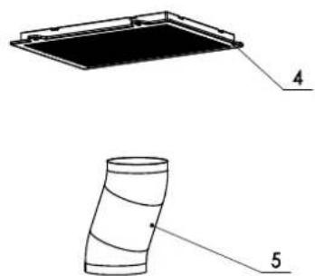
text_image
Technical diagram showing two views of a flexible panel or duct, labeled with numbers 4 and 5.| Ref | Q'ty Components | |
| 1 | 1 | Bottom Panel Ass |
| 2 | 2 | Flu Cover Ass |
| 3 | 1 | Wind housing Ass |
| 4 | 1 | Charoal filter Ass |
| 5 | 1 | Telescopic duct |
| 6 | 2 | Aluminum Foil |
| 7 | 2 | Sponge ring |
| 8 | 2 | Recirculating T- pieces |
| 9 | 1 | Recirculating T- pieces |
| 10 | 4 Screws(ST4×10) | |
| 11 | 10 | Screws(M4×10) |
| 12 | 4 Screws(ST4.8×40) | |
| 13 | 4 | Flat Washers |
| 14 | 4 | Plastic expansion plug |
INSTALLING THE HOOD
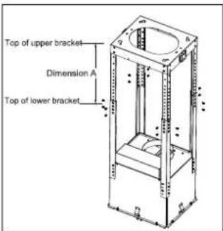
- Unscrew 16 screws between the two sections of the structure. Adjust extension of the hood support structure (dimension A). "Dimension A" represents the height from the top of upper bracket to the top of lower bracket. as the final height of the hood depends on this, and remember that with installation completed to the hood must be at least 650mm above the cooktop(Fig.2)
Fig.1
text_image
Top of upper bracket Dimension A Top of lower bracketFig.2
text_image
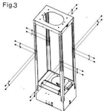
min500-max1000 500 344 DIM. A Cooktop type DIM.A minimum* maximum Gas 650mm 800mm Electric 650mm 800mm WARNING! Failure to install the screws or fixing device in accordance with these instructions may result in electrical hazards Top of hob- Fix the two sections of the structure using 16 screws(Fig.3).
natural_image
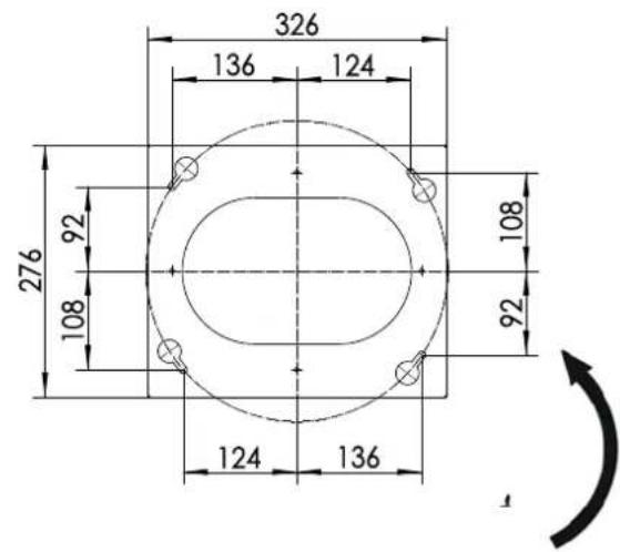
Technical line drawing of a mechanical assembly with no visible text or symbols- Place the ceiling hole diagram directly above the cook-top (the center of the diagram must match the center of the cook-top and the edges must be parallel to the sides of the cook-top) (Fig.4)
- Drill as shown(4 plugs). Screw 4 hood mounting screws leaving a space of about 5mm between the screw head and the ceiling. (Fig.4)
- Fix an exhaust pipe inside the truss and connect it to the motor compartment connection ring. (Fig.4)
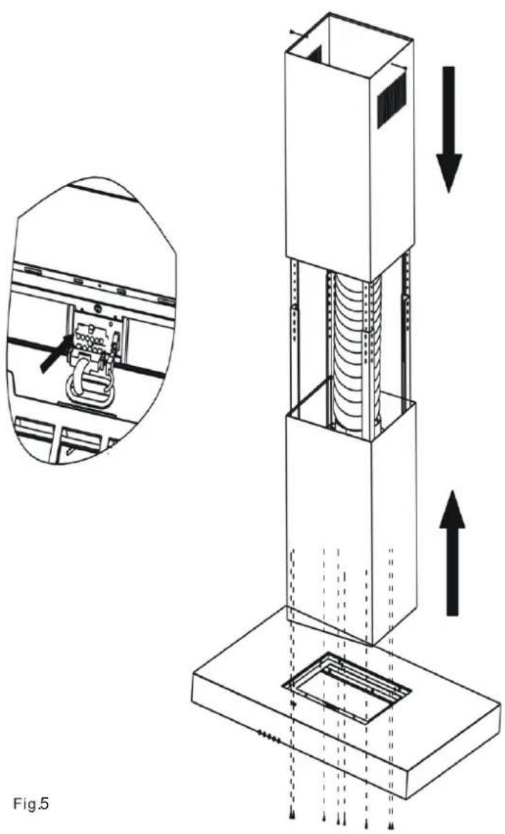
- Insert the top chimney into the truss, secure it with two screws. Insert the bottom chimney in its seat so that it completely covers the motor compartment and electrical connection box. (Fig.5)
- Hook the hood body onto the truss, ensuring it fits properly, secure the body to the truss with 8 screws then tighten it. (Fig.5)
- Tighten the 4 hood mounting screws.
- Remove the wire Cover within the body, Connect as shown the wire terminal and the controller terminal. Ensure the Wire Cover secure firmly with two screws.
- Connect the power source and turn the mains power check for correct hood operation.
text_image
326 136 124 276 92 108 108 92 124 136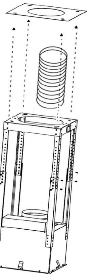
natural_image
Technical line drawing of a mechanical assembly with a coiled spring and housing frame (no text or symbols)Fig.4
natural_image
Technical diagram of a vertical mechanical device with internal components and directional arrows, shown in two views (no text or symbols)INSTALLING HOOD IN RECIRCULATING MODE
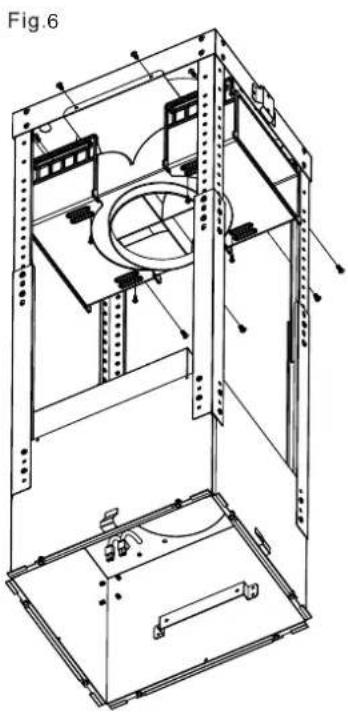
- Fix the recirculation plate to mounting plate with 4 supplied short screws. Fix the recirculation box with 8 supplied short screws as Fig 6.
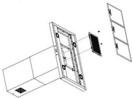
- Insert one side charcoal filter into the hood body, and lock the other side by two screws as Fig 7.
natural_image
Technical line drawing of a mechanical assembly with no visible text or symbolsFig.7
natural_image
Technical line drawing of a mechanical assembly with no visible text or symbolsELECTRICAL CONNECTION
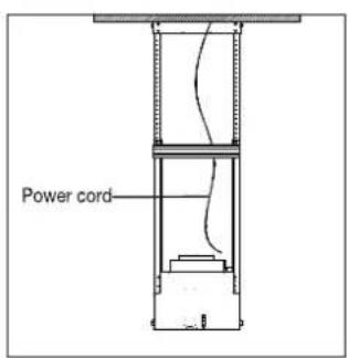
- Electrical wiring must be done by a qualified person(s) in accordance with all applicable codes and standards. Turn off electrical power at service entrance before wiring.
- If the power cord is damaged, it must be replaced by manufacturer, its agent or similarly qualified persons in order to avoid hazard.
- Do not use the plug and an extension cord other than the ones initially supplied with the hoods.
- The earthing of this hood is compulsory. Do not remove the ground prong of the plug.
Fig.8
text_image
Power cordOPERATION
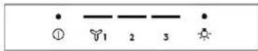
Press one of the speed 📋/ respiratory button to turn the appliance on.
| Button | Function |
| 1 | Press button 1 to turn on or turn off the model. |
| Press button for low speed. | |
| Press button for medium speed. | |
| Press button for high speed. | |
| Press button to turn on or turn off the light. |
LED LAMPS
Max Wattage:2 W
Voltage range:12V
WARNING: Always switch off the electrical supply before carrying out any operation on the appliance. This LED lamp should be replaced with qualified person.
CLEANING AND MAINTENANCE
Cleaning
DANGER
Always switch off the electricity supply at the breaker box during installation, cleaning, or maintenance.
NOTE
The efficiency of the range hood depends on the cleanliness of the intake and filters. Grease should not be allowed to accumulate on hood or filter.
- Clean the appliance in the following intervals:
| Regularly | Use a soft cloth moistened with hand-warm mildly soapy water or household cleaning detergent. Never use metal pads, chemical, abrasive material or stiff brush to clean the appliance. |
| Monthly | Aluminum filter: The filter collects grease, smoke and dust so the filter is directly affecting the efficiency of the range hood. If not cleaned, the grease residue(potential flammable) will saturate on the filter. Clean it with household cleaning detergent. The filter is dishwasher safe. Recirculation box: clean the ventilation openings on the top sides. |
| Every 4 - 6 months | Charcoal filters:If the model is not vented to the outside, the air will be recirculated through disposable charcoal filters that help remove smoke and odors.The charcoal filters cannot be cleaned, they must be replaced regularly (depending on range hood usage).Note: Do not rinse or put charcoal filters in a dishwasher.Note: Charcoal filters are not included with the range hood. |
Maintenance
- User service-Do not repair or replace any part of the appliance unless specifically recommended in the manual. All other servicing should be referred to a qualified technician.
TROUBLE SHOOTING
| Problem | Cause | Solution |
| Excessive vibration. | The appliance in not fixed properly on the brackets. | Take down the appliance and check it is properly fixed. |
| The fan blade is damaged. | Switch off the appliance. Repair to be carried out by qualified service personnel only. | |
| The fan motor is not fixed tightly. | ||
| Light on, but fan does not work. | The fan blade is jammed. | |
| The motor is damaged. | ||
| Both light and fan do not work. | Light bulb broken. | Replace with a bulb with correct rating. |
| Problem with electrical connection. | Check the electrical connection with an electrician. | |
| Suction performance is not good. | Distance between the appliance and the cooking place too large. | Readjust the distance. |
| Metallic anti-grease filter is dirty. | Clean filters(see Cleaning and maintenance). | |
| Charcoal filter is dirty. | Charcoal filter(see Cleaning and maintenance). |
CONSUMER CARE CENTER
| ThailandConsumer Care Tel : (+66 2) 725 9000Electrolux Thailand Co., Ltd.Electrolux Building 14th Floor1910 New Phetchaburi Road,Bangkapi, Huai Khwang, Bangkok 10310Office Tel : (+66 2) 7259100Office Fax : (+66 2) 7259299Email : customercarethai@electrolux.com | SingaporeConsumer Care Center Tel: (+65) 6727 3699Electrolux S.E.A. Pte Ltd.351 Braddell Road#01-04, 351 On BraddellSingapore 579713Email : customer-care.sin@electrolux.com |
| IndonesiaHotline service: 08041119999PT. Electrolux IndonesiaElectrolux BuildingJl.Abdul Muis No.34, Petrojo Selatan,Gambir Jakarta Pusat 10160Email:customercare@electrolux.co.idSMS & WA : 0812.8088.8863 | PhilippinesConsumer Care Center Toll Free:1-800-10-845-CARE(2273)Consumer Care Hotline:(+63 2)845-CARE(2273)Electrolux Philippines,Inc.Unit B 12F Cyber Sigma Bldg, Lawton Avenue,McKinley West,Taguig, Philippines 1634Trunkline:+63 2 737-4757Website:www.electrolux.com.phEmail:wecare@electrolux.com |
| VietnamConsumer Care Center Toll Free1800-58-88-99Tel: (+84 28) 39105465Electrolux Vietnam Ltd.Unit 1&2, 10F Sofic Tower, #10 Mai Chi Tho Street,Thu Thiem Ward, Thu Duc City, Ho ChiMinh City, Vietnam | MalaysiaConsumer Care Center Tel: 1300-88-11-22Electrolux Home Appliances Sdn. Bhd.Corporate Office Address: Unit T2-7, 7th Floor,Tower 2, PJ33, No. 3, Jalan Semangat,Seksyen 13,46200 Petaling Jaya, Selangor.Office Tel : (+60 3) 7843 5999Office Fax : (+60 3) 7955 5511Consumer Care Center Address: Lot C6, No. 28,Jalan 15/22, Taman Perindustrian Tiong Nam,40200 Shah Alam, SelangorConsumer Care Center Fax : (+60 3) 5524 2521Email : malaysia.customercare@electrolux.com |
| HONG KONGSERVICE HOTLINE: (+852) 3193 9888DCH ELECTRICAL APPLIANCESSERVICE CENTRE4/F, DCH BUILDING, 20 KAI CHEUNG ROAD,KOWLOON BAY, HONG KONGEMAIL: customercare@dch.com.hkWEBSITE: www.electrolux.com.hk |
www.electrolux.com
The Thoughtful Design Innovator.
Do you remember the last time you opened a gift that made you say, "Oh! How did you know? That's exactly what I wanted!" That's the kind of feeling that we at Electrolux seek to evoke in everyone who chooses or uses one of our products. We devote time, knowledge, and a great deal of thought to anticipating and creating the kind of appliances that our customers really need and want.
This kind of thoughtful care means innovating with insight. Not design for design's sake, but design for the user's sake. For us, thoughtful design means making appliances easier to use and tasks more enjoyable to perform, freeing our customers to experience the ultimate 21st century luxury: ease of mind. Our aim is to make this ease of mind more available to more people in more parts of their everyday lives, all over the world.
The “Thinking of you” promise from Electrolux goes beyond meeting the needs of today’s consumers. It also means we’re committed to making appliances safe for the environment—now and for future generations.
Electrolux. Thinking of you.
Share more of our thinking at www.electrolux.com