MUTO Premium - Door Dormakaba - Free user manual and instructions
Find the device manual for free MUTO Premium Dormakaba in PDF.


| Product Type | Telescopic Sliding Door System with Sidelites |
| Model | MUTO Premium XL80 |
| Brand | Dormakaba |
| Panel Configuration | 2 or 4 panels (Slow Moving Panel and Quick Moving Panel) |
| Maximum Door Leaf Weight per Panel | ≤176 lbs (80 kg) |
| Glass Requirements | Fully tempered monolithic or laminated glass (ASTM C 1036/1048) |
| Glass Thickness Options | 3/8" (10 mm), 1/2" (12 mm), 17/32" (13.5 mm) |
| Mounting Type | Ceiling mount with sidelites |
| Operation | Manual sliding (slow opening and closing only) |
| Optional Damping System | Dormotion start/stop unit |
| Safety Features | Anti-jump mechanism, adjustable end stops, moving floor guide |
| Track System | XL80 telescopic |
| Required Tools | Hex keys (2.5, 3, 4, 5 mm), wrenches, torque wrench |
| Maintenance and Care | Clean with damp cloth; use silicone-free cleaners; inspect regularly |
| Spare Parts | Use only original dormakaba parts |
| Intended Use | Dry indoor areas only |
| Installation Requirements | Two qualified persons, protective clothing, suitable substructure |
| Disposal | In accordance with local, state, and national regulations |
| Adhesive for Laminated Glass | 3M Scotch-Weld Urethane Adhesive DP 605 NS (working life 5 min, full cure 48 hrs) |
| Clearance Bottom of Glass to Floor | 3/8" (10 mm) |
Frequently Asked Questions - MUTO Premium Dormakaba
User questions about MUTO Premium Dormakaba
0 question about this device. Answer the ones you know or ask your own.
Ask a new question about this device
Download the instructions for your Door in PDF format for free! Find your manual MUTO Premium - Dormakaba and take your electronic device back in hand. On this page are published all the documents necessary for the use of your device. MUTO Premium by Dormakaba.
USER MANUAL MUTO Premium Dormakaba
natural_image
Technical line drawing of a cabinet or enclosure with two vertical panels and mounting feet (no text or symbols)MUTO Premium
XL80 Telescopic - Ceiling Mount with Sidelites
with Moving Floor Guide
Dormotion (DM) optional
Installation instructions
936043 - 05-2021
| EN |
Table of contents
1 Technical specifications 3
1.1 Overview 3
1.1.1 General information 3
1.1.2 Intended use 3
1.1.3 Glass requirements/fittings/mounting 3
1.1.4 Requirements for glass panel 3
1.1.5 Safety instructions 3
1.1.6 Symbols used - Safety/Installation 3
1.1.7 Maintenance, care, repair 3
1.1.8 Disposal 3
1.2 Specification - technical data 4
1.3 Tempered laminate glass (TLG) and adhesive specifications 4
2 Installation preparation 5
2.1 Overall 5
2.2 Door/wall dimensions 6
3 Installation instructions - Slow moving panel (SMP)
3.1 Installing end stops in SMP 7
3.2 Securing gasket to SMP track 7
3.3 Securing sidelite section profile to SMP track 8
3.4 Specifications for securing track to mounting surface 8
3.5 Installing U-Channel for sidelite 9
3.6 Installing sidelite glass 9
3.7 Installing sidelite glass filler panel 10
3.8 Installing sidelite glass gasket 10
3.9A Installing roller carriers: on SMP monolithic glass ONLY 11
3.9B Installing roller carriers: on SMP tempered laminate glass ONLY 12
3.10 Adjust roller carrier wheels 13
3.11 Disengage the anti-jump 13
3.12 Assemble simultaneous drive 14
3.13 Secure moving floor guide 15
3.14 Install glass/rollers in SMP track 16
3.15 Install floor guide 16
3.16 Install floor guide: continued 17
3.17 Engaging anti-jump 17
3.18 Adjustment door height 17
3.19 Adjustment end stop location: LEADING end stop Adjustment end stop location: TRAILING end stop 18
4 Installation instructions -
Quick moving panel (QMP) 19
4.1 Installing end stops in QMP 19
4.2 Connecting the doors via the cable bracket 19
4.3 Securing track for QMP 20
4.4 Secure clamp profile for QMP 21
4.5 Install hook set (less Dormotion) 21
4.6 Installing roller carriers 22
4.7 Installing DORMOTION start/stop (optional) 23
4.8 Disengaging the anti-jump 23
4.9 Install glass/rollers in QMP track 24
4.10 Engaging anti-jump 24
4.11 Align the cable 25
4.12 Adjustment end stop location:
LEADING end stop
Adjustment end stop location:
TRAILING end stop 26
4.13 Securing the cable to the QMP cable clamp 27
4.14 Install DORMOTION unit into QMP track (optional) 28
4.15 Adjust start/stop pin height (if necessary) 29
4.16 QMP track cover and end caps 30
4.17 SMP cover profile 31
4.18 Cover profile for passage 32
4.19 Cover clips 32
4.20 Cover spacers 33
4.21 Install brush profile 33
4.22 Secure system cover 34
1 Technical specifications
1.1 Overview
These instructions are for installation of MUTO Premium XL80 Telescopic panels for the following mounting and style versions:
1. Ceiling mount with Sidelite
1.1.1 General information
- dormakaba requires use of tempered laminated or tempered monolithic glass.
- dormakaba glass hardware is not suitable for harsh environment; for example, applications where chemicals (e.g. chlorine) are used such as indoor swimming pools, saunas, or salt-water pools.
- Never move sliding panels faster than walking speed and always stop the door manually before it reaches end position.
- Do not slide doors with excessive force. Ensure proper installation of limiting stop to prevent door from opening too far.
1.1.2 Intended use
- For sliding doors in dry indoor areas only.
- For manual slow opening and closing only.
1.1.3 Glass requirements/fittings/mounting
- The substructure/wall must be able to bear permanent loads, be level (max. tolerance: 1/16" [2] per 39" [1m]).
- Fasteners must be sufficiently dimensioned for the substructure/wall and weight of the door.
- When adjusting glass components, always stick to the required clearance for the respective hardware. Adjust clearance so glass does not come in contact with any hard surfaces such as glass, metal or concrete.
- Do not use excessive force when installing the glass (avoid over tightening screws.)
1.1.4 Requirements for glass panel
- dormakaba requires use of fully tempered glass, which complies with ASTM C 1036 and ASTM C 1048. Secondary heat soaking processes are recommended but not required. This applies to both tempered monolithic and tempered laminated glass.
- Clamping area must be flat and uncoated (no self-cleaning coating!)
- Never use glass with conchoidal fractures and/or damaged edges.
1.1.5 Safety instructions
• Installation requires two people.
• Always wear protective clothing.
- Only properly qualified and specially trained staff are authorized to mount dormakaba glass hardware.
- Due to crushing hazards and possible injury caused by breakage of glass during mounting, corresponding protective clothing (especially gloves and protective goggles) is required.
- Never clamp metal fitting hardware directly to glass surface.
1.1.6 Symbols used - Safety/Installation

CAUTION
Mounting components must meet the requirements of substructure/wall and door weight. Please read the technical information for fittings.

WARNING
Risk of breaking glass. When installing the door, support the door panel with a block of wood or similar object.

TIPS AND RECOMMENDATIONS
Information note

CLOSING EDGE OF DOOR
1.1.7 Maintenance, care, repair
- Immediately replace damaged parts.
• Always use original dormakaba parts. - Clean clamping area with alcohol-based standard commercial cleaning agent before mounting the glass hardware.
- Use a damp cloth for occasional cleaning.
• Always use silicone - and oil-free cleaners (e.g. acetone). - Check glass hardware at regular intervals for proper positioning, smooth operation and correct adjustment.
- High traffic door systems require inspection by properly qualified staff (specialized companies or installation firms.)
1.1.8 Disposal
Disposal in accordance with local, state and national regulations.
1.2 Specification - technical data
| 2 panels 4 panels | |||
| XL80 Telescopic XL80 Telescopic | |||
| Ceiling mount | Door leaf weight lbs [kg] * 2 x ≤176lbs | [2 x ≤80] | 4 x ≤176lbs[4 x ≤80] |
| * Including weight of auxiliary hardware. | |||
| LEGEND |
| SMP Slow moving panel |
| QMP Quick moving panel |
1.3 Tempered laminate glass (TLG) and adhesive specifications
| Required parts for laminate glass with MUTO System (not included) | Part Number Quantity Usage recommendation | |
| 3M^TM Scotch-WeldTM Urethane Adhesive, DP 605 NS | 934.800 1 tube | 1 tube per 4 roller carriers |
| 3M^TM Scotch-WeldTM EPXTM Plus II Applicator with 1:1 Plunger2 | 934.801 1 applicator | 1:1 plunger with 934.800 adhesive |
| 3M^TM Scotch-WeldTM EPXTM Plus II Mixing Square Nozzle, 5.3mm3 | 934.805 Pk of 4 | 4 nozzles per 1 tube of adhesive |
| MUTO TLG gasket set | 807.640 1 set | |
| Handling time frame | Function | Time |
| Working life (time between application and clamping of carrier) | 5 minutes @ 75°F | |
| Handling strength | 20 minutes @ 73°F or more | |
| Full cure time (normal door usage not recommended until full cure time has been met) | 48 hours @ 73°F or more | |
NOTE: Door glass should not be installed until the full cure time as been reached (see chart above).
1.1 Clean clamping area with alcohol-based standard commercial cleaning agent before mounting the glass hardware.
Important safety-related information for the mounting and use of dormakaba glass hardware.
1.2 Never clamp metal fitting hardware directly to glass surface.
1.3 Never use clamping products on surfaces with self-cleaning coatings.
2 Scotch-Weld™ EPX™ Plus II Applicator with 1:1 Plunger is a trademark of 3M.
3 Scotch-Weld™ EPX™ Plus II Mixing Square Nozzle is a trademark of 3M.
2 Installation preparation
2.1 Overall
Fig 1

1.18 Sidelite section profile
1.19 Filler panel
1.20 U-channel
1.21 U-channel gaskets
1.22 Sidelite glass gasket
1.23 Cover spacers (x2)
1.11 Start/stop (optional)
1.12 Simultaneous drive
1.13 Floor guide
1.14 Moving floor guide
1.15 Quick Moving Panel clamp
1.16 QMP Roller carriers (x2)
1.17 QMP glass clamp end
caps (x2)
1.6 Cover clips
1.7 Dormotion unit (x2)
(optional)
1.8 Cover profile for Slow Moving Panel
1.9 Cover profile for passage
1.10 SMP Roller carriers (x2)
1.1 Cover
1.2 Brush strip
1.3 Quick Moving Panel
track
1.4 End stops (x4)
1.5 Slow Moving Panel
LACK
2.2 Door/wall dimensions
2 panel - Right (shown) or Left hand opening
![clear opening height (CH) clear opening width (CW) (SMP) Slow moving panel (QMP) Fixed panel (FP) Quick moving panel 1-3/16" [30] 1-3/16" [30] 1/8" [3]](/content/2026/05/765507/images/6caaa328612d86a0bcb62546460625e22fc71bc36482747d32cf9f60f285688d.jpg)
![Back of track to center of mounting hole in track 1-1/2" [38] 3-11/16" [85] Bottom of glass to floor 3/8" [10] 9/16" [14]](/content/2026/05/765507/images/03f56ab9fda6a0f8a50f5597391d34e8b4dab01fa255b289e00b73aae8820ef1.jpg)
4 panel - Bi-parting opening

flowchart
graph TD
    A["Fixed panel"] --> B["(FP)"]
    B --> C["SMP"]
    C --> D["Slow moving panel"]
    D --> E["1-3/16" [30"]]
    E --> F["1-3/16" [30"]]
    F --> G["(QMP)"]
    G --> H["Quick moving panel"]
    H --> I["1-1/4" [6"]]
    I --> J["1-3/16" [30"]]
    J --> K["(QMP)"]
    K --> L["Quick moving panel"]
    L --> M["1-1/4" [6"]]
    M --> N["1-3/16" [30"]]
    N --> O["(SMP)"]
    O --> P["Slow moving panel"]
    P --> Q["1-3/16" [30"]]
    Q --> R["(SMP)"]
    R --> S["Slow moving panel"]
    S --> T["1-3/16" [30"]]
    T --> U["(SMP)"]
    U --> V["Slow moving panel"]
    V --> W["1-3/16" [30"]]
    W --> X["(SMP)"]
    X --> Y["Slow moving panel"]
    Y --> Z["1-3/16" [30"]]
    Z --> AA["(SMP)"]
    AA --> AB["Slow moving panel"]
    AB --> AC["1-3/16" [30"]]
    AC --> AD["(SMP)"]
    AD --> AE["Slow moving panel"]
    AE --> AF["1-3/16" [30"]]
    AF --> AG["(SMP)"]
    AG --> AH["Slow moving panel"]
    AH --> AI["1-3/16" [30"]]
    AI --> AJ["(SMP)"]
    AJ --> AK["Slow moving panel"]
    AK --> AL["1-3/16" [30"]]
    AL --> AM["(SMP)"]
    AM --> AN["Slow moving panel"]
    AN --> AO["1-3/16" [30"]]
    AO --> AP["(SMP)"]
    AP --> AQ["Slow moving panel"]
    AQ --> AR["1-3/16" [30"]]
    AR --> AS["(SMP)"]
    AS --> AT["Slow moving panel"]
    AT --> AU["1-3/16" [30"]]
    AU --> AV["(SMP)"]
    AV --> AW["Slow moving panel"]
    AW --> AX["1-3/16" [30"]]
    AX --> AY["(SMP)"]
    AY --> AZ["Slow moving panel"]
    AZ --> BA["1-3/16" [30"]]
    BA --> BB["(SMP)"]
    BB --> BC["Slow moving panel"]
    BC --> BD["1-3/16" [30"]]
    BD --> BE["(SMP)"]
    BE --> BF["Slow moving panel"]
    BF --> BG["1-3/16" [30"]]
    BG --> BH["(SMP)"]
    BH --> BI["Slow moving panel"]
    BI --> BJ["1-3/16" [30"]]
    BJ --> BK["(SMP)"]
    BK --> BL["Slow moving panel"]
    BL --> BM["1-3/16" [30"]]
    BM --> BN["(SMP)"]
    BN --> BO["Slow moving panel"]
    BO --> BP["1-3/16" [30"]]
    BP --> BQ["(SMP)"]
    BQ --> BR["Slow moving panel"]
    BR --> BS["1-3/16" [30"]]
    BS --> BT["(SMP)"]
    BT --> BU["Slow moving panel"]
    BU --> BV["1-3/16" [30"]]
    BV --> BW["(SMP)"]
    BW --> BX["Slow moving panel"]
    BX --> BY["1-3/16" [30"]]
    BY --> BZ["(SMP)"]
    BZ --> CA["Slow moving panel"]
    CA --> CB["1-3/16" [30"]]
    CB --> CC["(SMP)"]
    CC --> CD["Slow moving panel"]
    CD --> CE["1-3/16" [30"]]
    CE --> CF["(SMP)"]
    CF --> CG["Slow moving panel"]
    CG --> CH["1-3/16" [30"]]
    CH --> CI["(SMP)"]
    CI --> CJ["Slow moving panel"]
    CJ --> CK["1-3/16" [30"]]
    CK --> CL["(SMP)"]
    CL --> CD
    style A fill:#f9f,stroke:#333
    style B fill:#ccf,stroke:#333
    style C fill:#cfc,stroke:#333
    style D fill:#fcc,stroke:#333
    style E fill:#cff,stroke:#333
    style F fill:#ffc,stroke:#333
    style G fill:#fcf,stroke:#333
    style H fill:#cff,stroke:#333
    style I fill:#ffc,stroke:#333
    style J fill:#cfc,stroke:#333
    style K fill:#cfc,stroke:#333
    style L fill:#cfc,stroke:#333
    style M fill:#cfc,stroke:#333
    style N fill:#cfc,stroke:#333
    style O fill:#cfc,stroke:#333
    style P fill:#cfc,stroke:#333
    style Q fill:#cfc,stroke:#333
    style R fill:#cfc,stroke:#333
    style S fill:#cfc,stroke:#333
    style T fill:#cfc,stroke:#333
    style U fill:#cfc,stroke:#333
    style V fill:#cfc,stroke:#333
    style W fill:#cfc,stroke:#333
    style X fill:#cfc,stroke:#333
    style Y fill:#cfc,stroke:#333
    style Z fill:#cfc,stroke:#333
3 Installation instructions - Slow moving panel (SMP)
3.1 Installing end stops in SMP
Fig 2
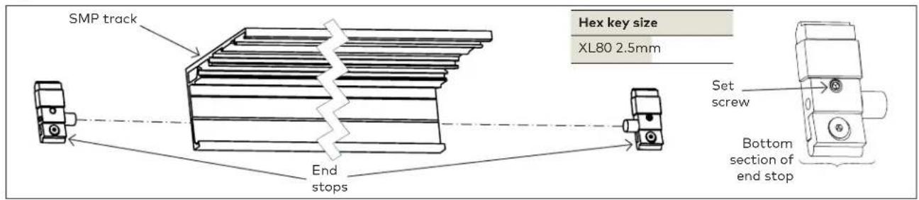
3.1.1 Slide end stops into each end of the SMP track.
NOTE: Loosen bottom section of end stop for easier install.
NOTE: Exact location/adjustments will be determined in the Adjustment End Stop Location step.
3.2 Securing gasket to SMP track
Fig 3

3.2.1 Ensure the SMP track is cut to proper length.
NOTE: SEE DIMENSION INSTRUCTIONS ON PAGE 9.
3.2.2 Cut adhesive gasket equal to sidelite glass width.
3.2.3 Adhere gasket along bottom edge of back of track.
3.3 Securing sidelite section profile to SMP track
Fig 4

3.3.1 Align sidelite profile holes with SMP track profile holes.
NOTE: Holes will be predrilled every 7-7/8" [200].
3.3.2 Secure with 9/16" (14) fasteners provided.
NOTE: Be sure fastener heads are flush with track to avoid rollers catching protruding fasteners.
3.4 Specifications for securing track to mounting surface
3.4.1 Ensure track is properly level and secure it to the header mounting surface per the appropriate measurements on the following page.
NOTE: SEE DIMENSION INSTRUCTIONS ON PAGE 6 FOR REFERENCE.
3.4.2 Use appropriate fasteners according to the following recommendations.
NOTE:
OVERHEAD REINFORCEMENT:
The overhead reinforcement must be a minimum of 14 " [6] x 3" [76] steel angle, 16 gauge metal stud with wood blocking, or two pieces of 1-1/2" [38] thick wood blocking (double stacked), secured to studs or joists on a maximum 16" [406] centers for the length of the track. The overhead reinforcement may be flush on the overhead surface or on the interior of this surface.
Track mounting screws must fully penetrate the steel angle, metal stud, or at a minimum of 2" [51] into wood blocking, utilizing the predrilled holes in the MUTO track.
Consult with a structural engineer to determine if reinforcement is adequate for your specific application or to meet specific codes in your location.
3.5 Installing U-Channel for sidelite
Fig 5

3.5.1 Install gaskets as shown. Trim to correct length.
3.5.2 Secure u-channel to floor using appropriate fasteners.
NOTE: Ensure u-channel is plumb and the back of the U-channel profile aligns with back of sidelite profile. NOTE: Gaskets are pre-installed.
3.6 Installing sidelite glass
Fig 6

3.6.1 Place setting blocks into u-channel.
3.6.2 Spray inside of u-channel with glass cleaner.
3.6.3 Lift glass up and into sidelite profile.
3.6.4 Lower glass into u-channel.
3.6.5 Ensure there is 1/8" [3] gap between wall and edge of sidelite glass.
3.6.6 If using tempered laminated glass, gently press glass against u-channel gasket, and dispense silicone along full length of non-gasket side of u-channel.
3.7 Installing sidelite glass filler panel
Fig 7

3.7.1 Fit filler panel between empty section of track and sidelite profile, on door side.
3.8 Installing sidelite glass gasket
Fig 8

3.8.1 Cut gasket to length.
3.8.2 Press gasket in between sidelite glass and sidelite profile.
3.9A Installing roller carriers: on SMP monolithic glass ONLY
Fig 9
![DETERMINE THE LEADING (X) VERSUS TRAILING (Z) EDGE OF THE GLASS. "LEADING IS SIDE CLOSEST TO LATCH CLOSED." *ENSURE CARRIERS ARE SECURED TO CORRECT SIDE OF GLASS.* Torque values XL80 5 ft lbs [6Nm] Hex key size XL80 3mm Roller location on glass XL80 SMP X 2-3/8" [60] SMP Z 2-3/8" [60] Secure Glass gasket (Front of) Glass Roller carrier Legend Closing edge of door (Front of) Glass](/content/2026/05/765507/images/cc23f0110eeaaefc6895f701b0aac9fd0cf066dbc1143119f7a1fe58dc2756ca.jpg)

NOTE: FULLY CLEAN SURFACE OF GLASS WITH AN ALCOHOL-BASED MILD GLASS AND SURFACE CLEANER.

ENSURE GASKET IS FREE OF DEBRIS.

ENSURE ROLLER CARRIER WHEELS ARE FREE OF DEBRIS.
3.9A.1 Slide SMP roller carriers onto glass.
3.9A.2 Slide glass gasket and metal shim between glass and roller carrier.
NOTE: Orient with gasket facing the glass.
3.9A.3 Secure roller carriers to glass at 5 ft lbs (6 Nm).
3.9B Installing roller carriers: on SMP tempered laminate glass ONLY
Fig 10
![DETERMINE THE LEADING (X) VERSUS TRAILING (Z) EDGE OF THE GLASS. "LEADING IS SIDE CLOSEST TO LATCH CLOSED." *Ensure carriers are secured to correct side of glass.* Torque values XL80 4ft lbs [5Nm] Hex key size XL80 3mm Roller location on glass SMP X 2-3/8" [60] SMP Z 2-3/8" [60] Legend Closing edge of door Secure Glass gasket (Front of) Glass 3M™ Scotch- Weld™ EPXTM Plus II Applicator Stop when adhesive can be seen past end of roller carrier. (Front of) Glass (Back of) Glass](/content/2026/05/765507/images/45cee7cd7566b50c0eb229ef90b87f1266266340c7bce7ddd294237a28a413c5.jpg)
NOTE: THE RECOMMENDED ADHESIVE'S SET-UP TIME IS 20 MINUTES FOR THE DUO-PAK CARTRIDGES.
NOTE: USE 1:1 RATIO PLUNGER WITH THE 3M^TM Scotch-Weld™ Urethane Adhesive.
NOTE: FULLY CLEAN SURFACE OF GLASS WITH AN ALCOHOL-BASED MILD GLASS AND SURFACE CLEANER. ENSURE NO DEBRIS IS ON THE GASKET.
ENSURE ROLLER CARRIER WHEELS ARE FREE OF DEBRIS.
3.9B.1 Slide SMP carriers onto glass.
3.9B.2 Replace existing gasket with TLG gasket.
3.9B.3 Slide laminated glass gasket and metal shim between glass and roller carrier.
NOTE: Orient with gasket facing the glass.
3.9B.4 Relace existing set screws with vented set screws.
3.9B.5 Tighten vented set screws at 4 ft lbs (5Nm).
NOTE: Onto scrap material, first dispense approximately 12" of 3M™ Scotch-Weld™ Urethane Adhesive prior to application to prevent mixing errors and ensure optimal hardening.
3.9B.6 Dispense into vented set screws on both sides of carrier.
Stop application when adhesive can be seen past edge of roller carrier.
DO NOT WIPE any excess adhesive from glass surface. Allow adhesive to dry and scrape off glass surface with a beveled-edge chisel or putty knife.
NOTE: Keep glass flat during curing process.
NOTE: See chart in Specifications section for appropriate curing time.
3.10 Adjust roller carrier wheels
Fig 11
![Wheel Front of carrier +3/16" [+5] -1/8" [-3] Wheel adjustment Screw Carrier bracket Back of carrier Carrier bracket Front of carrier Wheel Carrier bracket Wheel +3/16" [+5] adjustment Screw -1/8" [-3] Back of carrier Carrier bracket Hex key size XL80 5mm](/content/2026/05/765507/images/2a264a67b8ab09a25c08ff7ca0648299d0fbbb71b2e259b1c098a92b6aa03a57.jpg)
3.10.1 If more clearance is required between wheel and track, adjust accordingly.
3.10.2 Loosen wheel adjustment screw.
3.10.3 Slide wheel up or down to adjust.
3.10.4 Retighten wheel adjustment screw.
3.11 Disengage the anti-jump
Fig 12
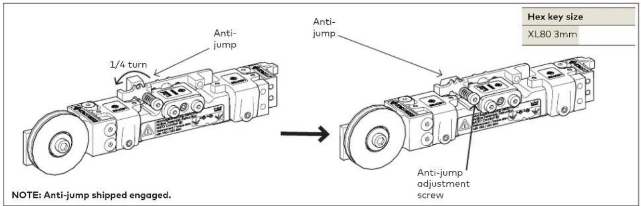
3.11.1 Disengage the anti-jump on SMP roller carrier.
3.11.2 Using a hex key, push anti-jump adjustment screw IN and turn COUNTER-CLOCKWISE 90° to disengage anti-jump.
3.12 Assemble simultaneous drive
Fig 13
![Fig. 1 Fig. 2 Fig. 3 Fig. 4 3.12.1 Assemble cable as shown above in Figures 1-4. 3.12.2 Measure and cut cable. Cable length = (SMP door width x 2) + 39" [991] Drive-cable bracket NOTE: MANUALLY DOUBLE CHECK CABLE LENGTH BEFORE CUTTING. 3.12.3 Loop cable assembly around SMP carriers as shown. ENSURE BRACKET IS CENTERED ON TRAILING CARRIER. Wrench size XL80 5.5mm C-wrench Hex key size XL80 2mm, 5mm Feed free end of cable in here Secure free-end of cable Drive-cable bracket *ENSURE PROPER ORIENTATION* Fig. 5 3.12.4 After cable is looped around, feed free-end through open side of bracket. 3.12.5 Secure free-end of cable inside bracket. • Fully tighten to 2.2ft lbs [3Nm]. 3.12.6 Fully tension cable via nut on inside of bracket. • To tighten: rotate wrench CLOCKWISE. Fig. 6 3.12.7 Tighten outside nut to lock into place. • To tighten: hold inside nut with one wrench, rotate second wrench on outside nut COUNTER-CLOCKWISE.](/content/2026/05/765507/images/a76ff3cb260f1f999355159ce8b5a60b16bac14909026670fc0dc84387d7bae8.jpg)
3.13 Secure moving floor guide
Fig 14
![Plate #1 Plate #2 3/32" [2] 1/32" [1] 1/32" [1] 1/32" [1] Plate #4 Fasteners * Right hand floor guide shown.* Hex key size XL80 2mm, 5mm Plate #1/#2 Plate #3 (Adhesive gasket) *Ensure adhesive side faces up.* Plate #4 Glass thickness [mm] 3/8" [10] 1/2" [12] 17/32" [13.5] Plate #1 X Plate #2 X Plate #3 XXXX Plate #4 XXXX Fastener lengths 1/2" [12] 5/8" [16] 5/8" [16] ±1/16" [2]](/content/2026/05/765507/images/7366a7fae3d4b7525c73abda8cfd4d060b239bd996ec1c7fc3f275ad28a60ffc.jpg)
3.13.1 Secure moving floor guide to SMP.
3.13.2 Use chart to determine appropriate plate(s) needed for glass thickness.
3.13.3 Orient as shown.
3.14 Install glass/rollers in SMP track
Fig 15

ENSURE ROLLERS AND TRACK ARE FREE OF DEBRIS.
3.14.1 Place SMP glass on setting blocks on floor for stability.
3.14.2 Lift glass and SMP rollers up and rest rollers on SMP track.
*If installing/hanging tempered laminated glass panels, ensure carrier adhesive has cured for 48 hours minimum. See Specifications section for more information regarding cure time.*
![Hex key size XL80 3mm Floor guide anchor Ø5/16" [8] 1-1 3/32" [36]](/content/2026/05/765507/images/9dd372ccf60a0176e25e25534bfb69c324f506fc74b76f774a0af3c0db0beb10.jpg)

AUTION ANTI-JUMP IS DISENGAGED!
3.15.1 Align centerline of glass with centerline of floor guide.
3.15.2 Be sure the glass is plumb.
3.15.3 Mark appropriate floor guide measurements.
3.15.4 TEMPORARILY REMOVE GLASS AND ROLLERS FROM TRACK.
3.15.5 Pre-drill into mounting surface using a 5/16" drill bit.
3.15.6 Secure floor guide anchor with included fasteners.
3.16 Install floor guide: continued
Fig 17

Hex key size
XL80 2.5mm

3.16.1 SET GLASS AND ROLLERS BACK ONTO TRACK.
3.17 Engaging anti-jump
Fig 18
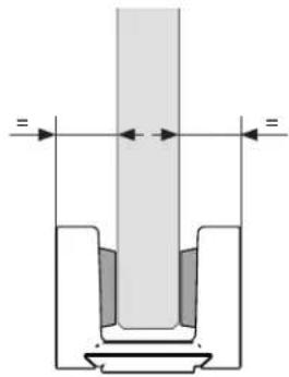
3.16.2 Slide floor guide over floor guide anchor and tighten with set screws.
3.16.3 Remove setting blocks.
NOTE: Be sure glass is centered in floor guide. Adjust using set screws.
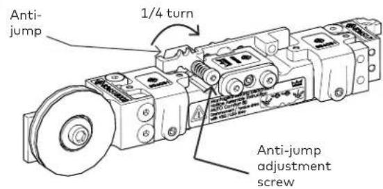

3.17.1 Engage anti-jump on roller carrier.
3.17.2 Using a hex key, push anti-jump adjustment screw IN and turn CLOCKWISE 90° to engage anti-jump.
3.18 Adjustment door height
Fig 19
![SMP Glass Floor guide +3/16" [+5] -1/8" [-3] 3/8" [10]](/content/2026/05/765507/images/6a3d6861858ea0ac62af4c9a4dc3258805f3f313d750749dd82ea410db8e980b.jpg)
Door height adjustment tolerance
XL80
+3/16" [+5] -1/8" [-3]
XL80 torque
Height 2 ft lbs
adjustment [3 Nm]
screws

XL80 torque
Height 4 ft lbs
adjustment [6 Nm]
locking screws
Hex key size
XL80 3mm
3.18.1 Set height of glass door.
3.18.2 Loosen height adjustment locking screws on carrier.
3.18.3 Using appropriate size hex key, turn height adjustment screw CLOCKWISE or COUNTER-CLOCKWISE to raise or lower glass.
NOTE: Be sure glass is level during this adjustment.
3.19 Adjustment end stop
location: LEADING end stop
Fig 20

Set end stop location:
3.19.1 Slide end stop to desired location on track. Bumper should touch edge of roller carrier.
Hex key size
XL80 2.5mm
Legend
NOTE: Bi-foldering: Be sure there is a 1/4" [6] gap between the right and left hand sets.
Adjustment end stop
location: TRAILING end stop
Fig 21

Set end stop location:
3.19.1 Slide end stop to desired location on track. Bumper should touch edge of roller carrier.
Hex key size
XL80 2.5mm
Legend
NOTE: Bi-foldering: Be sure there is a 1/4" [6] gap between the right and left hand sets.
4 Installation instructions - Quick moving panel (QMP)
4.1 Installing end stops in QMP
Fig 22
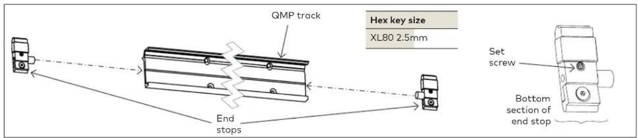
4.1.1 Slide end stops into each end of the QMP tracks.
NOTE: Loosen bottom section of end stop for easier install.
NOTE: Exact location/adjustments will be determined in the Adjustment End Stop Location step.
4.2 Connecting the doors via the cable bracket
Fig 23

4.2.1 Push both door panels towards the closing edge.
4.2.2 Secure cable bracket with two fasteners through the QMP track at 2 ft lbs [2.5Nm].
4.3 Securing track for QMP
Fig 24
![SMP track QMP track SMP track 3-15/16" [100] Hex key size XL80 3mm QMP track QMP track M5 x 10 Flat head socket cap screw 10mm 5mm](/content/2026/05/765507/images/0856aeebd6971574c59e8a956503bae64cb89b998b9d3246f9b2be3403957962.jpg)
4.3.1 Secure QMP track to SMP track.
4.3.2 Secure included fasteners at 2 ft lbs [2.5Nm].
4.4 Secure clamp profile for QMP
Fig 25
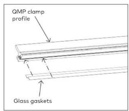


NOTE: FULLY CLEAN SURFACE OF GLASS WITH AN ALCOHOL-BASED MILD GLASS AND SURFACE CLEANER.
4.4.1 Add glass gaskets. Trim to proper length.
4.4.2 Secure QMP glass to glass clamp profile.
4.4.3 Tighten all fasteners at 4ft lbs [5Nm].
- Do not overtighten pressure plate against glass.
- Start at center of profile and work outwards.
4.5 Install hook set (less Dormotion)
Fig 26
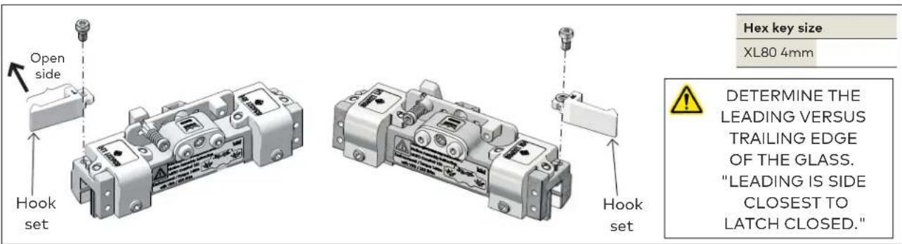
4.5.1 With rollers facing away from the installer, determine which roller will be leading and which will be trailing.
4.5.2 Secure hook onto roller with open side facing away from the installer.
4.5.3 Secure hook using appropriate-size hex key.
4.6 Installing roller carriers
Fig 27
![DETERMINE THE LEADING (X) VERSUS TRAILING (Z) EDGE OF THE GLASS. "LEADING IS SIDE CLOSEST TO LATCH CLOSED." *CARRIER WITH CABLE CLAMP TO BE SECURED TO TRAILING SIDE OF GLASS.* Torque values XL80 5 ft lbs [6Nm] Hex key size XL80 3mm Roller location on glass XL80 QMP X 3-1/8" [80] QMP Z 1-9/16" [40] Legend Closing edge of door Glass clamp Glass gasket Glass clamp profile (Front of) Glass Roller carrier Secure (Front of) Glass](/content/2026/05/765507/images/23023e6e644e32a1314883617e9a72c0436218b02a32d8bc2c5a96c1479db1bd.jpg)
NOTE: FULLY CLEAN SURFACE OF CLAMP PROFILE WITH AN ALCOHOL-BASED MILD GLASS AND SURFACE CLEANER.
ENSURE GASKET IS FREE OF DEBRIS.
ENSURE ROLLER CARRIER WHEELS ARE FREE OF DEBRIS.
4.6.1 Slide QMP roller carriers onto clamp profile.
4.6.2 Slide gasket and metal shim between clamp profile and roller carrier.
NOTE: Orient with gasket facing the clamp profile.
4.6.3 Secure roller carriers to clamp profile at 5 ft lbs (6 Nm).
4.7 Installing DORMOTION start/stop (optional)
Fig 28

PRODUCT SHIPPED WITH 7/8" [22] PIN INSTALLED. PIN CAN BE CHANGED TO 1" [25] IF NECESSARY.
![Start/stop pin 7/8" [22] Images not to scale 1" [25]](/content/2026/05/765507/images/0df51aa7f0f119d4807bee5786d431362b70510aed6c0e22affbaff5c6914bc5.jpg)

Torque
Set screws 3 ft lbs [3 Nm]
Hex key size
Set screws 3 mm
Hex screws 3 mm

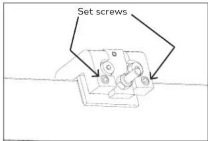
NOTE: Determine a pin length based upon how square and plumb the opening is.
4.7.1 If required, change pin in start/stop assembly.
- Remove hex screws.
- Remove existing pin and plate.
- Swap in appropriate pin and plate.
- Replace hex screws.
4.7.2 Slide start/stop onto glass.
4.7.3 Center equally between the carriers.
4.7.4 Slide glass gasket between start/stop and glass.
NOTE: Orient with gasket facing glass.
4.7.5 Secure start/stop via set screws.
4.8 Disengaging the anti-jump
Fig 29

4.8.1 Disengage the anti-jump on roller carrier. 4.8.2 Using the appropriate size hex key, push anti-jump adjustment screw IN and turn COUNTER-CLOCKWISE 90° to disengage anti-jump.
4.9 Install glass/rollers in QMP track
Fig 30

ENSURE ROLLERS AND TRACK ARE FREE OF DEBRIS.
4.9.1 Place QMP glass on setting blocks on floor for stability.
4.9.2 Lift glass and QMP rollers up and rest rollers on track.

4.10 Engaging anti-jump
Fig 31

4.10.1 Engage anti-jump on roller carrier.
4.10.2 Using a hex key, push anti-jump adjustment screw IN and turn CLOCKWISE 90° to engage anti-jump.
4.11 Align the cable
Fig 32
VIEW FROM BACK OF SYSTEM -
SMP AND QMP TRACKS REMOVED FOR EASIER VIEWING.

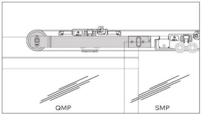
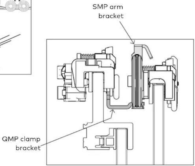
4.11.1 Slide SMP arm bracket over top of the QMP carrier clamp bracket.
4.11.2 Jump the arm bracket over the clamp bracket to align cable with clamp bracket.

4.12 Adjustment end stop
location: LEADING end stop
Fig 33

XL80 torque
2 ft lbs
[3 Nm]
Hand tighten
Hex key size
XL80 2.5mm
NOTE: Bi-folding: Be sure there is a 1/4" [6] gap between the right and left hand sets.
Set end stop location:
4.12.1 Slide end stop to desired location on track. Bumper should touch edge of roller carrier.
Adjustment end stop
location: TRAILING end stop
Fig 34

Set end stop location:
4.12.1 Slide end
stop to desired location on track.
Bumper should touch edge of roller carrier.
XL80 torque
2 ft lbs [3 Nm] Hand tighten
Hex key size
XL80 2.5mm
NOTE: Bi-folding: Be sure there is a 1/4" [6] gap between the right and left hand sets.
Legend
Closing edge of door
4.13 Securing the cable to the QMP cable clamp
Fig 35

Hex key size
XL80 Cross-head screw driver (magnetic recommended)
*VIEWED FROM BACK OF TRACK/CARRIERS*

4.13.3 Align cable inside clamp.
4.13.4 Reinsert and retighten all screws.
4.13.1 Remove cable clamp set screws #1 and #2.
4.13.2 Loosen cable clamp set screws #3 and #4.
4.14 Install DORMOTION unit into QMP track (optional)
Fig 36
DISREGARD IF SYSTEM IS LESS DORMOTION
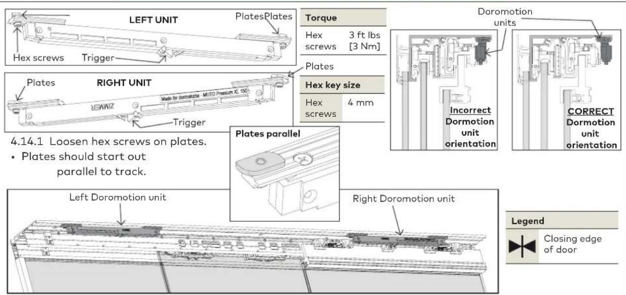
- Plates should start out parallel to track.
Closing edge of door
4.14.2 Place appropriate DORMOTION unit into each end of the track channel, in general locations.
LOCATING THE DORMOTION UNIT

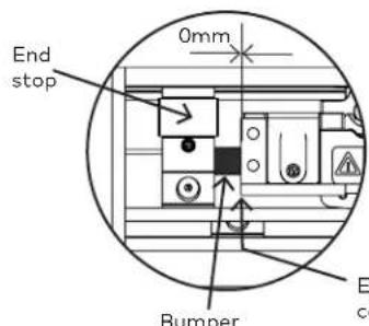
4.14.3 Slide door all the way OPEN.
4.14.4 Carrier should touch end stop.
4.14.5 Slide Dormotion unit over until trigger aligns with start/stop pin.
4.14.6 Rotate plates inside track to engage.
4.14.7 Tighten hex screws with 3 ft lbs [3Nm] of torque.

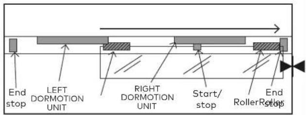

4.14.3 Slide door all the way CLOSED.
4.14.4 Carrier should touch end stop.
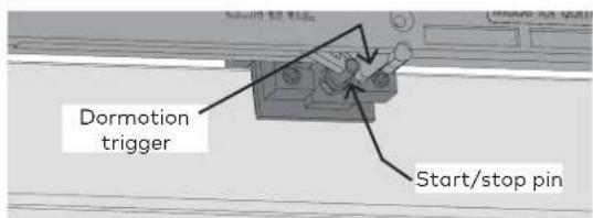
4.14.5 Slide Dormotion unit over until trigger aligns with start/stop pin.
4.14.6 Rotate plates inside track to engage.
4.14.7 Tighten hex screws with 3 ft lbs [3Nm] of torque.
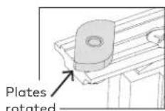
4.15 Adjust start/stop pin height (if necessary)
Fig 37
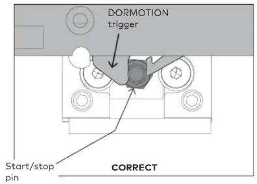


4.15.1 Adjust HEIGHT of start/stop pin, if necessary:
- Loosen hex screws.
- Slide pin and plate up or down.
| Hex key size | |
| Hex screws | 3 mm |
4.16 QMP track cover and end caps
Fig 38

4.16.1 Add adhesive foam pieces to QMP glass clamp profile, spaced accordingly.
4.16.2 Peel off adhesive.
4.16.1 Slide cover over outside of profile.
4.16.2 Peel adhesive off end caps and press onto ends of profile.
4.17 SMP cover profile
Fig 39

4.17.1 Slide doors fully CLOSED.
4.17.2 Slide SMP cover profile up and between the SMP roller carriers as shown in Fig. 1 above.
4.17.3 Secure with included fasteners.
4.18 Cover profile for passage
Fig 40

4.18.1 Slide both doors all the way OPEN.
4.18.2 Slide cover profile for passage up behind QMP track.
4.18.3 Secure cover profile for passage with all included fasteners at 2 ft lbs [2.5Nm].
4.19 Cover clips
Fig 41

natural_image
Three-step diagram showing a structural assembly with grid elements, one being lifted by an arrow (no text or symbols present)4.19.1 Insert cover clips into track (one clip per foot).
4.19.2 Insert perpendicular to track, and turn CLOCKWISE to snap into place.
4.20 Cover spacers
Fig 42
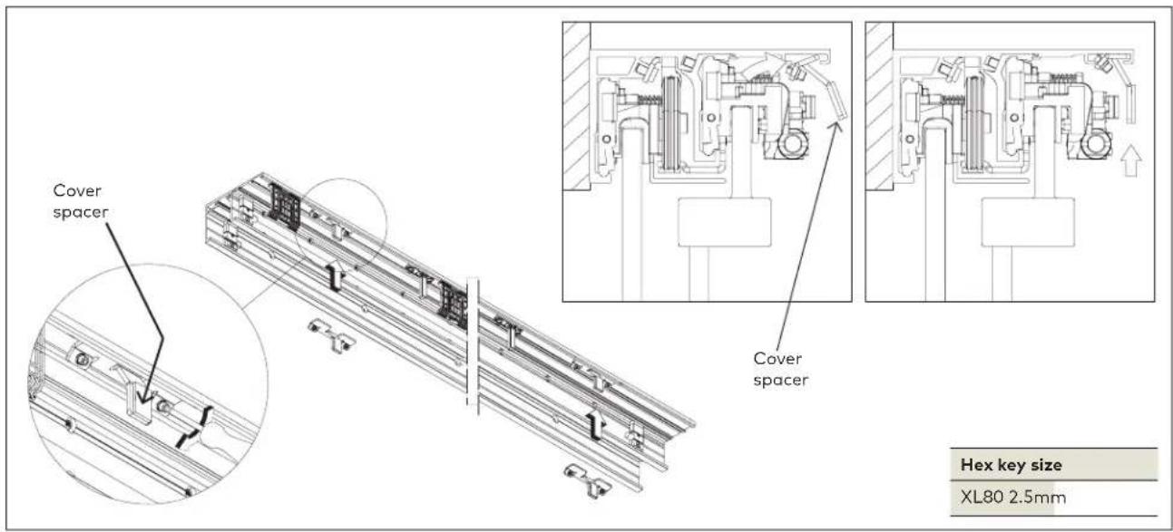
4.20.1 Tip cover spacers into outer most edge of track.
4.20.2 Place one at each end of track as shown.
4.20.3 Tighten at at hand tighten.
4.21 Install brush profile

4.21.1 Match brush to cover length. 4.21.2 Slide brush into cover.
4.22 Secure system cover

4.22.1 Secure cover to clips and snap into place.
NOTE: Roll cover from the bottom upwards. Ensure the bottom of the cover is supported by the groove in the cover clip.
4.22.2 Snap end caps onto track.
- MUTO Premium
- Installation instructions
- Table of contents
- Technical specifications 3
- Installation preparation 5
- Installation instructions - Slow moving panel (SMP)
- Installation instructions -
- Quick moving panel (QMP) 19
- Technical specifications
- Overview
- Ceiling mount with Sidelite
- General information
- Intended use
- Glass requirements/fittings/mounting
- Requirements for glass panel
- Safety instructions
- Symbols used - Safety/Installation
- CAUTION
- WARNING
- TIPS AND RECOMMENDATIONS
- CLOSING EDGE OF DOOR
- Maintenance, care, repair
- Disposal
- Specification - technical data
- Tempered laminate glass (TLG) and adhesive specifications
- NOTE: Door glass should not be installed until the full cure time as been reached (see chart above).
- Important safety-related information for the mounting and use of dormakaba glass hardware.
- Installation preparation
- Overall
- Door/wall dimensions
- Installing end stops in SMP
- Securing gasket to SMP track
- Securing sidelite section profile to SMP track
- Specifications for securing track to mounting surface
- NOTE:
- OVERHEAD REINFORCEMENT:
- Installing U-Channel for sidelite
- Installing sidelite glass
- Installing sidelite glass filler panel
- Installing sidelite glass gasket
- 3.9A Installing roller carriers: on SMP monolithic glass ONLY
- 3.9B Installing roller carriers: on SMP tempered laminate glass ONLY
- NOTE: Orient with gasket facing the glass.
- Adjust roller carrier wheels
- Disengage the anti-jump
- Assemble simultaneous drive
- Secure moving floor guide
- Install glass/rollers in SMP track
- ENSURE ROLLERS AND TRACK ARE FREE OF DEBRIS.
- AUTION ANTI-JUMP IS DISENGAGED!
- TEMPORARILY REMOVE GLASS AND ROLLERS FROM TRACK.
- Install floor guide: continued
- SET GLASS AND ROLLERS BACK ONTO TRACK.
- Engaging anti-jump
- Adjustment door height
- Adjustment end stop
- Set end stop location:
- Adjustment end stop
- Installation instructions - Quick moving panel (QMP)
- Installing end stops in QMP
- Connecting the doors via the cable bracket
- Securing track for QMP
- Secure clamp profile for QMP
- NOTE: FULLY CLEAN SURFACE OF GLASS WITH AN ALCOHOL-BASED MILD GLASS AND SURFACE CLEANER.
- Install hook set (less Dormotion)
- Installing roller carriers
- Installing DORMOTION start/stop (optional)
- Torque
- Hex key size
- NOTE: Determine a pin length based upon how square and plumb the opening is.
- NOTE: Orient with gasket facing glass.
- Disengaging the anti-jump
- Install glass/rollers in QMP track
- Engaging anti-jump
- Align the cable
- Adjustment end stop
- Securing the cable to the QMP cable clamp
- Install DORMOTION unit into QMP track (optional)
- Adjust start/stop pin height (if necessary)
- Adjust HEIGHT of start/stop pin, if necessary:
- QMP track cover and end caps
- SMP cover profile
- Cover profile for passage
- Cover clips
- Cover spacers
- Install brush profile
- Secure system cover
Brand : Dormakaba
Model : MUTO Premium
Category : Door