
36200UAK52 - Sewing machine Union Special - Free user manual and instructions
Find the device manual for free 36200UAK52 Union Special in PDF.


User questions about 36200UAK52 Union Special
0 question about this device. Answer the ones you know or ask your own.
Ask a new question about this device
Download the instructions for your Sewing machine in PDF format for free! Find your manual 36200UAK52 - Union Special and take your electronic device back in hand. On this page are published all the documents necessary for the use of your device. 36200UAK52 by Union Special.
USER MANUAL 36200UAK52 Union Special
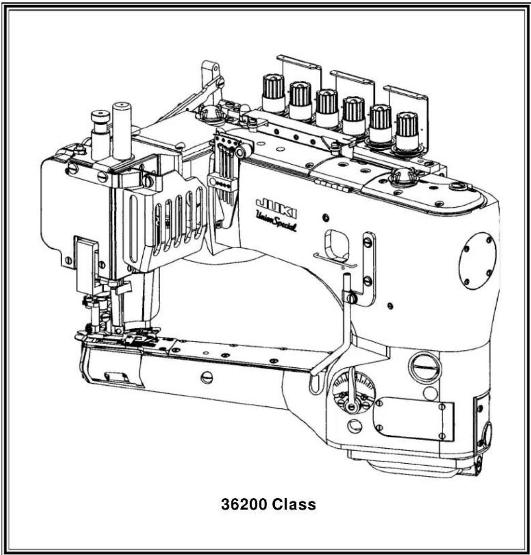
ADJUSTING INSTRUCTIONS / ILLUSTRATED PARTS LIST
text_image
36200 ClassMANUAL NO. PT0106
FORSTYLES
36200UA52 36200UH52 36200UX60
36200UAE52 36200UJ60 36200UY52
36200UAK52 36200UJE60 36200UY60
36200UE52 36200UM60
36200UE60 36200UX52
Second Edition Copyright 2002
By
Union Special Corporation Rights Reserved In All Countries
Printed in U.S.A. May 2002
PREFACE
This parts manual has been prepared to assist you in locating individual parts or assemblies on 36200 Series machines.
It is the desire of Union Special that each machine run at its optimum performance. Parts listed in this manual are designed specifically for your machine and are manufactured with utmost precision to assure long lasting service.
This manual has been comprised on the basis of available information. Changes in design and/or improvements may incorporate a slight modification of configuration in illustrations or part numbers.
On the following pages are illustrations and terminology used in describing the parts used on 36200 Series machines.
TERMS
Prices are net cash and subject to change without notice. All shipments are forwarded F.O.B. shipping point. A charge is made to cover postage and insurance.
CONTENTS
PREFACE 2
TERMS 2
IDENTIFICATION OF MACHINES ....3
TORQUEREQUIREMENTS 3
DESCRIPTION OF MACHINES ....3
STYLEOFMACHINES 4
SAFETYRULES: 5
IDENTIFYINGPARTS 6
NEEDLES 6
APPLICATION 6
Threading 7
Oiling 8
ADJUSTINGINSTRUCTIONS 9
SETTING THE NEEDLE BAR HEIGHT & ALIGNMENT 9
SETTING THE NEEDLE BARHEIGHT & ALIGNMENT(CONT) 10
ALIGNING THE CYLINDER 10
SETTINGTHELOOPERTRAVEL 10
INSTRUCTIONS FOR USING SYNCHRONIZING GAUGE 21277CG.... 11
SETTINGTHESTITCHLENGTH 15
DIFFERENTIAL FEEDCONTROL 15
CONTENTS(CONT.)
SETTINGTHEPRESSERFOOT 15
SETTING THE PRESSER FOOT(CONT.) 16
SETTING THE PRESSER FOOT(CONT.) 17
SETTING THE KNIFEDRIVELEVER 17
SETTING THE KNIFE DRIVE LEVER(CONT.) 18
SETTING THE TRIMMING KNIVES FOR BUTT SEAMING (STYLES 36200UA52, UAE52, UAK52, UJ60, UJE60, UX52, UX60) ...... 18
SETTING THE TRIMMING KNIVES FOR LAP SEAMING (STYLES 36200UH52, UAE52, UE52, UE60, UJE60, UM60, UY52, UY60) ..... 18
SETTING THE TRIMMING KNIVES(ALL STYLES) 18
SETTING THE TRIMMING KNIVES (ALL STYLES) (CONT.) 19
NEEDLE THREAD ADJUSTMENTS 19
LOOPERTHREADADJUSTMENT 20
COVERTHREAD ADJUSTMENT 20
TENSIONRELEASE 20
HUNGFOOT ADJUSTMENT 21
SETTING THE LAP FORMER (STYLES 36200UAE52, UE52, UE60, UH52, UJE60, UM60, UY52, UY60) 21
LAP SEAMING 21
OIL SIGHT GAUGES, TOP COVERS & MISCELLANEOUSTAKEUP & EYELETPARTS 23
MAINFRAME, BUSHINGS & MISCELLANEOUSEYELET & COVERPARTS 25
MAIN SHAFT & MISCELLANEOUS OILING 27
CRANKSHAFT&NEEDLELEVERPARTS 29
TENSIONPARTS 31
DETACHABLEHEAD, HEAD COVERS, NEEDLE BAR & NEEDLE BAR HEAD 33
DETACHABLEHEAD, HEADCOVERS, NEEDLE BAR & NEEDLE BARHEAD(CONT.) 35
DIFFERENTIAL & MAIN FEED BARS, FEED DOGS & FEED LIFTECCENTRIC ASSEMBLY 37
FEEDDRIVE ASSEMBLY, FEEDROCKER & LOOPER AVOID PARTS 39
KNIFEDRIVINGPARTS 41
Each UNION SPECIAL machine is identified by a style number, which is stamped into the style plate affixed to the middle of the machine under the tension assembly.
The serial number is stamped in the casting at the right rear base of the machine.
TORQUE REQUIREMENTS
Torque (measured in inch-pounds) is a rotating force (in pounds applied through a distance by a lever (in inches or feet). This is accomplished by a wrench, screwdriver, etc. Many of these devices are available, which when set at the proper amount of torque will tighten the part to the correct amount and no tighter.
All straps and eccentrics should be tightened to 19-21 inch-pounds (22-24cm/kg) unless otherwise noted.
All other nuts, bolts, screws, etc. should be tightened by hand as tightly as possible, unless otherwise noted.
DESCRIPTIONOFMACHINES
Universal style, Feed-off-the-arm, high speed, medium throw, five or six thread machine. There are four needles and one retainer abreast, one looper and a manually adjusted differential feed control. There is an enclosed automatic lubricating system, filter type oil return pump, visual sight oil action and supply gauges. The maximum work space in front of the needles is 8 inches (203.2mm). Recommended maximum speed - 4200 R.P.M. for all Styles. Machines can be used on either table or pedestal mount.
STYLEOFMACHINES
| 36200UA52 | FLATSEAMER: For simultaneously trimming right and left plies and flatseaming knit undergarments, infants clothing and similar light to medium weight materials where closing elastic is required.Seam specifications 607-FSa-1. Components produce a .205" (5.2mm) wide seam. |
| 36200UAE52 | FLATSEAMER AND LAP FLATSEAMER: Same as 36200UJE60 except fitted with components to produce a .205"(5.2mm) wide seam. |
| 36200UAK52 | LAP FLATSEAMER: For trimming right ply only and lapseaming knit undergarments, infants clothing and similar light to medium weight materials where closing elastic is required. Seam specifications 607-LSa-1.Components produce a .205" (5.2mm) wide seam. |
| 36200UE52 | LAP FLATSEAMER: For simultaneously trimming right and left plies and lap seaming men's and woman's briefs,undergarments, sweatpants, sweatshirts, infant sleepers and similar garments. Flat sewing parts with lap seam presser foot and lapformer. Seam specifications 607LSa-1. Components produce a .205"(5.2mm) wide seam. |
| 36200UE60 | LAP FLATSEAMER: Same as 36200UE52 except fitted with components to produce a .236" (6.0mm) wide seam. |
| 36200UH52 | LAPFLATSEAMER: For simultaneously trimming right and left plies and lap seaming men's briefs shorts, and similar garments made of light to medium weight material where crossing elastic and heavy seams, such as leg bindings is necessary. The right section of the sewing parts are raised .050" (1.27mm) to assure a better lap seam.Seam specifications 607-LSa-1. Components produce a .205" (5.2mm) wide seam. |
| 36200UJ60 | FLATSEAMER: Same as 36200UA52 except fitted with components to produce a .236" (6.0mm) wide seam. |
| 36200UJE60 | FLATSEAMER: For simultaneously trimming right and left plies and flatseaming knit undergarments, infants clothing and similar light to medium weight materials where closing elastic is required.Seam specifications 607-FSa-1.LAPFLATSEAMER: For simultaneously trimming right and left plies and lap seaming men's briefs shorts, and similar garments made of light to medium weight material where crossing elastic and heavy seams, such as leg bindings is necessary. Seam specifications 607-LSa-1. (Machine includes sewing parts to sew both FSa-1 Flat (butt) seam and LSa-1 Lap seam.)Components produce a .236" (6.0mm) wide seam. |
| 36200UM60 | LAP FLATSEAMER: Same as 36200UH52 except fitted with components to produce a .236" (6mm) wide seam. |
| 36200UX52 | TAPESEAMER: Simultaneously trims right and left plies, joins and tapes the front of knit briefs in one operation. Fitted with a taping foot without coverthread that has the tape slot in front of the needle hole and folder that takes a 3/4" (19.0mm) knitted strip, cut with the wale, to produce a 7/16" (11.1mm) wide finished tape. Seam specifications 607(mod)-LSz-1(mod). Seam width is .205" (5.2mm). |
| 36200UX60 | TAPE SEAMER: Same as 36200UX52 except fitted with components to produce a .236" (6.0mm) wide seam. |
| 36200UY52 | LAPFLATSEAMER: For simultaneously trimming right and left plies and lap seaming operations on the leg openings of knitted boxer style briefs using wide knitted callerette material. Flat sewing parts with special lap seam presser foot and special lap former. Fitted with special thread bracket, long feed dogs," T" shaped yielding section with light weight spring, light presser bar spring and wear plates on presser foot.Seam specifications 607LSa-1. Components produce a .205(5.2mm) wide seam. |
| 36200UY60 | LAP FLATSEAMER: Same as 36200UY52 except fitted with components to produce a .236" (6.0mm) wide seam. |
SAFETYRULES:
- Before putting the machines described in this manual into service, carefully read the instructions. The starting of each machine is only permitted after taking notice of the instructions and by qualified operators.
IMPORTANT! Before putting the machine into service, also read the safety rules and instructions from the motor supplier.
-
Observe the national safety rules valid for your country.
-
The sewing machines described in this instruction manual are prohibited from being put into service until it has been ascertained that the sewing units which these sewing machines will be built into, have conformed with the EC Council Directives (89/392/EEC, Annex II B).
Each machine is only allowed to be used as foreseen. The foreseen use of the particular machine is described in paragraph "STYLES OF MACHINES" of this instruction manual. Another use, going beyond the description, is not as foreseen.
-
All safety devices must be in position when the machine is ready for work or in operation. Operation of the machine without the appertaining safety devices is prohibited.
-
Wear safety glasses.
-
In case of machine conversions and changes all valid safety rules must be considered. Conversions and changes are made at your own risk.
-
The warning hints in the instructions are marked with one of these two symbols:

- When doing the following the machine has to be disconnected from the power supply by turning off the main switch or by pulling out the main plug:
8.1 When threading needle(s), looper, spreader etc.
8.2 When replacing any parts such as needle(s), presser foot, throat plate, looper, spreader, feed dog, needle guard, folder, fabric guide etc.
8.3 When leaving the workplace and when the workplace is unattended.
8.4 When doing maintenance work.
8.5 When using clutch motors without actuation lock, wait until the motor is stopped totally.
- Maintenance, repair and conversion work (see item 8) must be done only by trained technicians or special skilled personnel under consideration of the instructions.
- Any work on the electrical equipment must be done by an electrician or under direction and supervision of special skilled personnel.
- Work on parts and equipment under electrical power is not permitted. Permissible exceptions are described in the applicable sections of standard sheet DIN VDE 0105.
- Before doing maintenance and repair work on the pneumatic equipment, the machine has to be disconnected from the compressed air supply. In case of existing residual air pressure, after disconnecting from compressed air supply (i.e. pneumatic equipment with air tank), the pressure has to be removed by bleeding.
ILLUSTRATIONS
This manual has been arranged to simplify ordering repair parts. Exploded views of various sections of the mechanism are shown so that the parts may be seen in their actual position in the machine. On the page opposite the illustration will be found a listing of the parts with their part numbers, description and the number of pieces required in the particular view being shown.
Numbers in the first column are reference numbers only, and merely indicate the position of the part in the illustration. The reference number should never be used in ordering parts. Always use the part number listed in the second column.
Component parts of sub-assemblies which can be furnished for repairs are indicated by indenting their descriptions under the description of the main sub-assembly. As an example refer to the following text.
-
29126 EC Upper Looper Drive Shaft Assembly 1
-
22503F Screw 1
-
39543E Cam Follower Locking Clamp 1
It will be noted in the previous example that the cam follower, bushing and cam guide and the upper looper drive shaft are not listed. The reason is that replacement of these parts individually is not recommended, so the complete upper looper drive shaft assembly should be ordered.
When a part is common to all machines covered in this manual, no specific usage will be mentioned in the description. However, when the parts for the various machines are not the same, the specific usage will be mentioned in the description and, if necessary, the difference will be shown in the illustration.
A numerical index of all the parts shown in this manual is located at the back. This will facilitate locating the illustration and description when only a part number is known.
IDENTIFYINGPARTS
Where the construction permits, each part is stamped with its part number. On some of the smaller parts and on those where construction does not permit, an identification letter is stamped in to distinguish the part from similar ones.
PLEASENOTE: Part numbers represent the same part, regardless of which manual they appear. On all orders please include part number, name and style of machine for which the part was ordered.
NEEDLES
Each needle has both a type and size number. The type number denotes the kind of shank, point, length, groove, finish and other details. The size number, stamped on the needle shank, denotes the largest diameter of the blade measured between the shank and the eye. Collectively, the type number and size number represent the complete symbol which is given on the label of all needles packed and sold by Union Special.
TYPEDESCRIPTION
118GAS Extra short, double groove, struck groove, .060" diameter shank, chromium plated needle. Sizes available 065/025, 070/027, 075/029, 080/032, 090/036.
118GBS Extra short, single groove, struck groove, spotted .060" diameter shank, chromium plated needle. Sizes available 075/029, 080/032.
118GHS Same as 118GBS, except with ball point. Sizes available 070/027, 075/029, 080/032.
118GJS Same as 118GHS, except with tapered blade and ball point. Sizes available 065/025, 070/027, 075/029.
118GKS Round shank, round point, extra short, double groove, struck groove, spotted, chromium plated needle. Sizes available 070/027, 075/029, 080/032.
36211 Retainer needle, no scarf, chromium plated. Sizes available 065/025, 070/027, 075/029.
APPLICATION
118GKS 075/029 Recommended for Styles:36200UA52, UAE52, UE52, UE60, UH52, UJ60, UJE60, UM60, UY52, UY60.
118GKS 080/032 Recommended for Styles: 36200UX52, UX60.
118GAS 065/025 Recommended for Style: 36200UAK52.
When changing the needle, make sure it is fully inserted in the needle driving arm before the clamp screw is tightened.
To have needles promptly and accurately filled, an empty package, a needle sample, or the type and size number should be forwarded. Use the description on the label. A complete order should read as follows: "100 needles, type 118 GKS, size 075/029".
THREADING
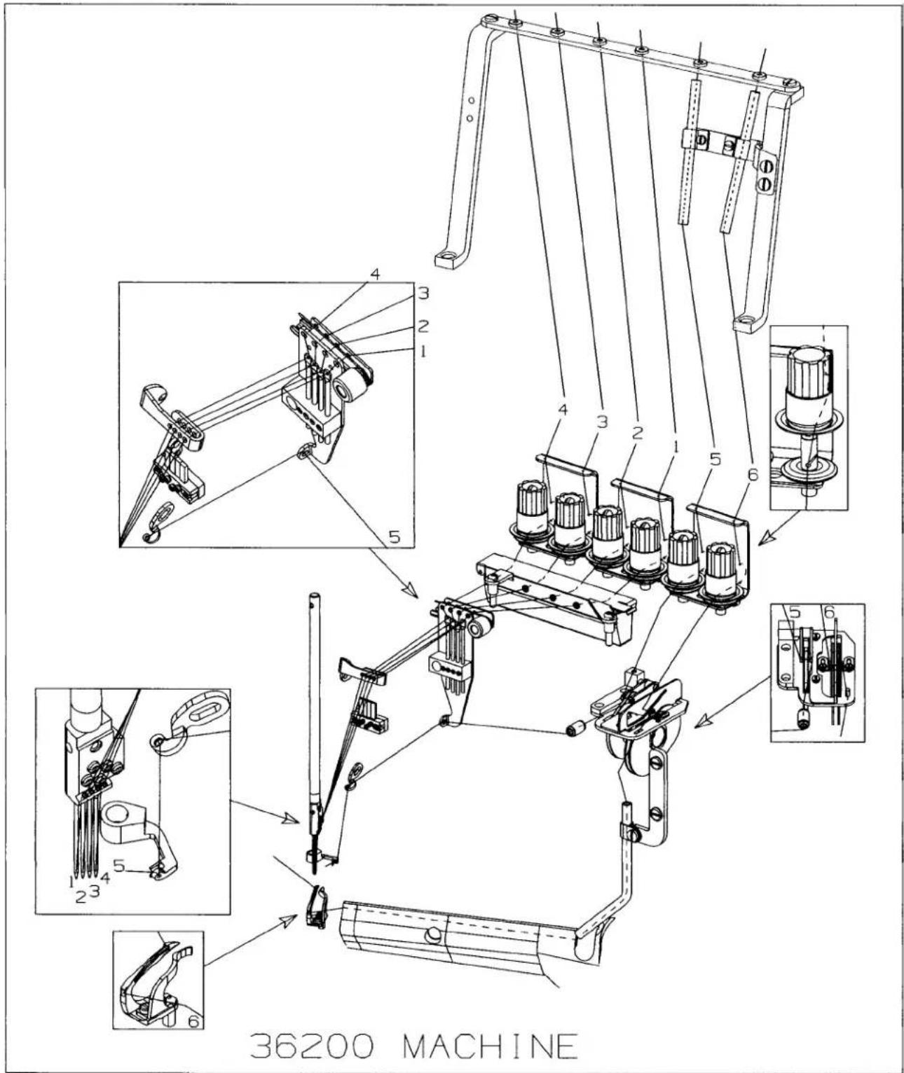
text_image
36200 MACHINEOILING
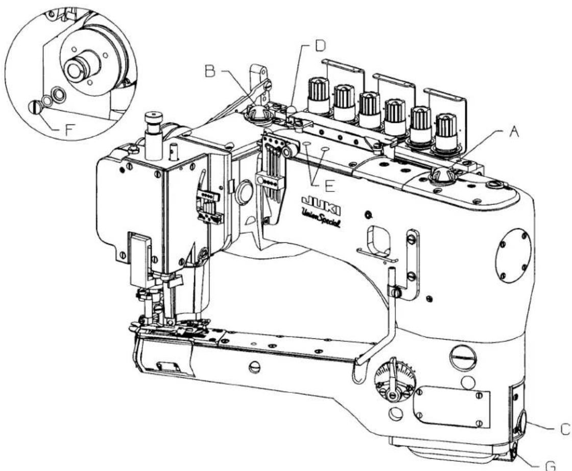
Referring to Fig. 1, fill the machine at (A) and (B). Oil capacity of class 36200 is 2.5 ounces in the bottom reservoir and 2.5 ounces in the top reservoir. Use a straight mineral oil, Saybolt viscosity of 90 to 125 seconds at 100^ Fahrenheit. The oil level is checked at gauges (C) and (D). Maintain oil level between the red lines of these gauges.
This machine is automatically lubricated by a continuously driven rotary pump. Oil flow can be observed through windows (A) and (B). When installing a new machine or starting a machine that has been idle for some time, priming may be necessary. Remove plug screws (E), fill holes with recommended oil and replace screws BEFORE operating. If oil does not flow while machine is running, pump is inoperative.
Remove screw 22733B (F, Fig. 1 inset) to drain oil from the top reservoir. To drain oil from bottom reservoir remove screw 999-196 (G).
Occasionally, it is necessary to oil the linkage of the presser foot, the knife holder shank (36273A), guide collar (36273K) and the various links and bearings of the presser foot lifting mechanism and thread tension release.
text_image
F B D A E JUKO Union Special C GFIG. 1
ADJUSTING INSTRUCTIONS
Instructions stating direction or location, such as right, left, front or rear of the machine are given relative to the operator's position at the machine unless otherwise noted. The handwheel rotates clockwise in operating direction.
SETTING THE NEEDLE BAR HEIGHT & ALIGNMENT
text_image
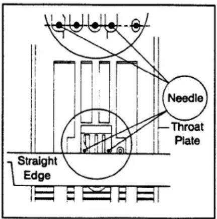
Straight Edge Throat Plate NeedleInsert the first (left) and fourth needles into the needle head. The needles for this Class of machine are made with two flats on the front of the shank. This will enable you to correctly position the needles in the needle head. Make certain the needle shank is fully inserted and that the screw is seated firmly on the flat.
To position the needle head square with the throat plate, use the upper knife or a straight edge to align the needles with the cross grooves in the throat plate. (See Fig. 2)
Refer to table 1 for the dimension from the fourth (lowest) needle to the surface of the throat plate and for the number of the needle bar height gauge.
FIG. 2
| ELYTS | MORFNOENEMID ENEL)TOW BAR HGIEOTELDEEN HGIEH EGUETALPTAOREGUAGSTEPECAFRUS RE3MUN DE | ||
| UA52, UAE52, UE52,5BRAU17/32" (13.5MM) | 21227BU | .531 | |
| UE60, UJ60, UJE60,UM60, UX60, UY60 | 1/2" (12 MM7 | 21227DS | .500 |
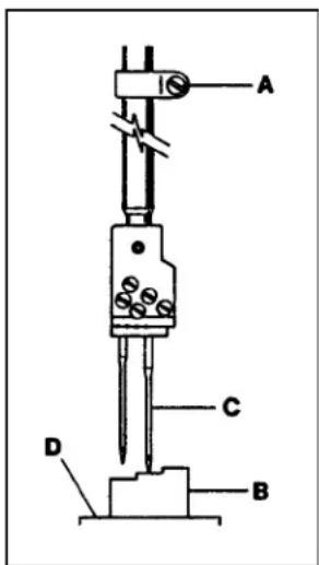
Position the needle bar at its highest point of travel. Loosen needle bar clamp screw (A, FIG.3) & use the specified needle bar height gauge (B) to achieve the desired height dimension from the fourth (lowest) needle (C) to the throat plate surface (D). Tighten clamp screw (A) and recheck setting. Care must be taken not to disturb the needle head alignment while making the adjustment. Add the two middle needles and the retainer.
TABLE1
text_image
A C D BFIG. 3
NOTE: Styles 36200UH52 and 36200UM60 have a .050" (1.3mm) step on the right side of the throat plate. When setting the needle height measure from the left side or lowest part of the stepped plate.
CAUTION: If the needle head has been replaced it must be torqued to 17 in. lbs. (20cm/kg). Or until torque bar (21227AR), inserted into cross hole in the needle bar, bends. It will not seat against the bottom of the needle bar. After tightening, check for expansion of the needle bar by positioning it up into the lower bushing hole. If the bar has expanded it will bind in the bushing. The bar must be replaced or lapped to reduce the bell shape. Align and set needle bar height as described above.
SETTING THE NEEDLE BAR HEIGHT & ALIGNMENT (CONT)
text_image
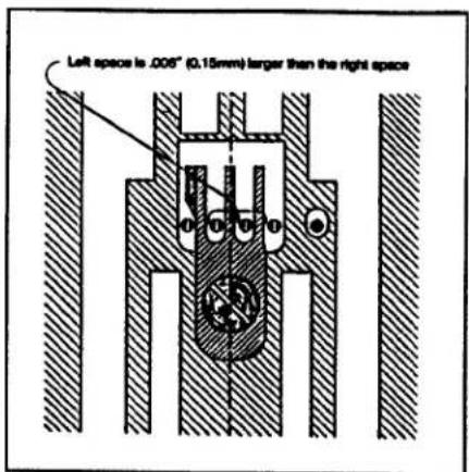
Left space is .005" (0.15mm) larger than the right spaceFIG. 4
Correct spacing of the needles in the throat plate stitch tongue is imperative to proper sewing conditions. Improper relationship of the needles to the stitch tongue often results in malformed stitches. When replacing the stitch tongue make sure needles are aligned properly (see Fig. 4).
If the stitch tongue and throat plate are properly seated and the needle position is not correct, the cylinder has probably been forced out of position. If realignment is necessary, refer to the section "Centering the Cylinder".
When the needles are correctly positioned in the throat plate the space to the left of the needles in the stitch tongue slot is .006" (0.15mm) more than the space to the right (see Fig. 4). Actually, the needle bar is centered to the throat plate and cylinder, however, to provide clearance on the left side of the needle for the needle loops passing around the looper during the down stroke of the needles, the slots in the stitch tongue are made off-center to the left. Accurate positioning of the needles may be obtained by repositioning the cylinder.
text_image
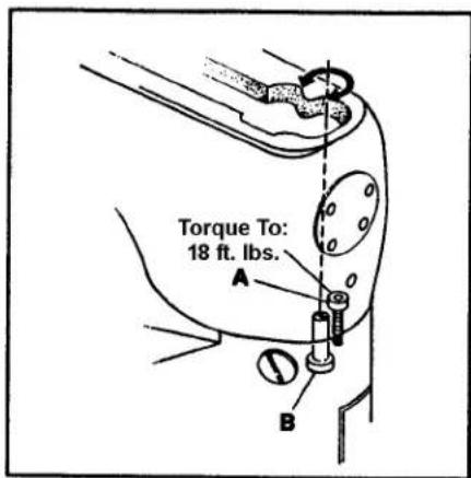
Torque To: 18 ft. lbs. A BFIG. 5
ALIGNING THE CYLINDER
Remove the top front cover and gasket from the main frame. Loosen cylinder holding screw (A, Fig. 5). Turn eccentric screw (B) clockwise to move the cylinder so the needles are closer to the right side of the stitch tongue. Turn the stud counterclockwise to locate the needles closer to the left. Tighten screw (A) and recheck settings.
NOTE: The cylinder may not move freely when the eccentric is turned because the joint sealant compound has set. Light tapping with a wooden block at the joint or midpoint of the arm may be necessary.
text_image
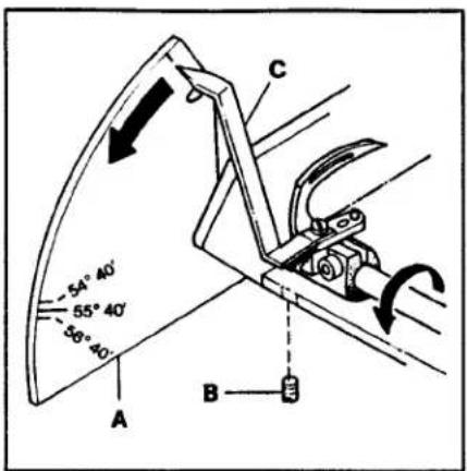
54° 40' 55° 40' 86° 40' A B CFIG. 6
SETTING THE LOOPER TRAVEL
Attach looper travel gauge plate (A, Fig. 6) to the rear of the cylinder arm. Set the bottom of the gauge so it is approximately horizontal and lock lightly in place with screw (B) directly underneath. Attach looper travel gauge pointer (C) to the looper using the left needle guard screw hole. Turn the handwheel in operating direction until the looper is positioned to the far right. Set pointer (C) at zero degrees by rotating gauge plate (A) and lock in place. Continue turning the handwheel until the pointer stops. If the looper travel is correct the pointer should indicate 55°40'.
SETTING THE LOOPER TRAVEL
text_image
Technical diagram showing mechanical assembly with labeled parts A and B, including a flange and bolted joint.FIG. 7
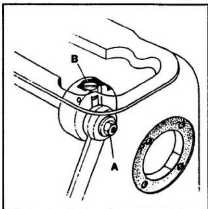
To adjust the looper travel remove the top front cover and the end cover. Loosen left-handed locknut (A, Fig. 7) and turn screw (B) clockwise to decrease the looper travel or counterclockwise to increase the looper travel. Tighten locknut (A) and recheck setting.
NOTE: After setting the looper travel the machine must be checked for synchronization.
TIMING THE NEEDLES TO THE LOOPER
To visually check the timing of the needles to the looper, turn the handwheel in operating direction until the needle bar has reached its lowest position and has risen 5/32" (4.0mm). At this time the looper point should appear at the same relative position to the needles whether rotation of handwheel is clockwise or counterclockwise.
INSTRUCTIONS FOR USING SYNCHRONIZING GAUGE 21277CG

text_image
A F B E C D 5/32" (4.0mm)FIG. 8
Turn the handwheel until the needle bar is at its lowest point. Loosen presser bar regulating screw (A, Fig. 8) and insert needle bar setting block (B) under the head of the screw (A) with stop screw (C) above needle bar (D). Tighten screw (A).
The long portion of the looper clamp and height gauge (E, Fig. 8) laid on its side is the 5/32" (4.0mm) gauge used to set the distance between stop screw (C) and the top of the needle bar (D) at its lowest position. Tighten nut (F) to clamp stop screw (C) into place.
TIMING THE NEEDLES TO THE LOOPER (CONT.)
text_image
Technical diagram of a mechanical device with labeled parts A through G, showing assembly and mounting details.FIG. 9
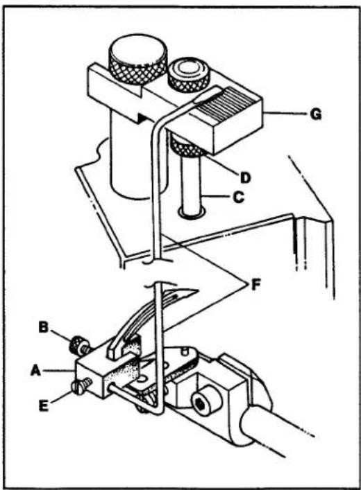
Attach the looper clamp and height gauge (A, Fig. 9) to the heal of the looper by tightening screw (B). Turn the handwheel slowly in a clockwise direction until needle bar (C) touches stop screw (D). Loosen screw (E) and set synchronizing gauge rod (F) so the flat end is on one of the lines in the center of the block (G). Tighten screw (E).
Turn the handwheel in the opposite direction until the needle bar touches stop screw (D, Fig. 9). Synchronizing rod (F) should come to the same line on block (G). The difference must not exceed one line.
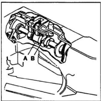
If the setting cannot be achieved, main shaft coupling (A, Fig. 10) must be repositioned. Remove the crank chamber cover and gasket. Loosen the three coupling screws (B). If synchronizing rod (F, Fig. 9) moves more to the right while the handwheel is rotated in a clockwise direction, the looper is too fast and the main shaft should be retarded. If the rod moves more to the right when the handwheel is rotated in a counterclockwise direction the looper is too slow and the mainshaft should be advanced. Tighten screws (B, Fig. 10).
NOTE: If the stationary Knife interferes with the synchronizing rod (F) remove the knife to make the adjustment.
text_image
A BFIG. 10
LOOPER ADJUSTMENTS
text_image
.094" (2.4mm) A C BFIG. 11
Looper Avoid
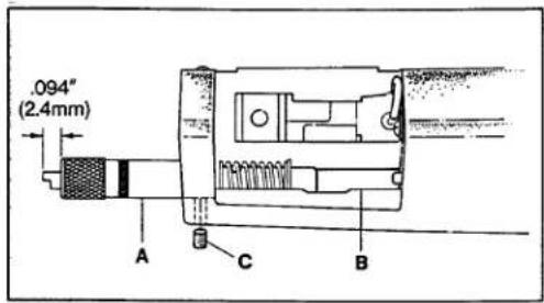
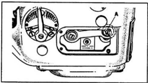
The looper avoid is set at .094" (2.4mm). Using gauge no. 21227BV (A, Fig. 11), position looper shaft (B) fully to the rear (away from operator) and insert the gauge through the looper shaft hole in the end of the cylinder until the plunger is fully extended from the gauge. Tighten clamp screw (C). When the looper is positioned fully to the front, the end of the plunger should be flush with the end of the gauge. The motion of the plunger from the extended position to flush represents .094" (2.4mm) travel. To adjust the looper avoid remove the cylinder cover and loosen screw (A, Fig. 12) with TT-85 wrench. Raise the ball joint to shorten the avoid motion or lower it to lengthen the avoid motion. Tighten screw (A). Reposition gauge (A, Fig. 11) and recheck the setting.
natural_image
Technical diagram of a mechanical component with gauges and housing (no visible text or symbols)FIG. 12
text_image
.018" to .025" (0.46mm to 0.64mm) Throat Plate C DFIG. 13
Vertical Adjustment of Looper
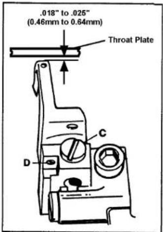
A clearance of .018" to .025" (0.46mm to 0.64mm) should be maintained between the top of the looper and the bottom of the stitch tongue. Loosen screw (C, Fig. 13) and turn screw (D), directly under the looper, up or down as required. Make sure the looper is seated and tighten screw (C). Check for clearance.
NOTE: On machine style 36200UAK52 looper sits on looper holder.
LOOPER ADJUSTMENTS (CONT.)
text_image
3/16" (4.8mm) A Left Needle B Looper Point .002" (0.05mm)FIG. 15
Looper Gauge
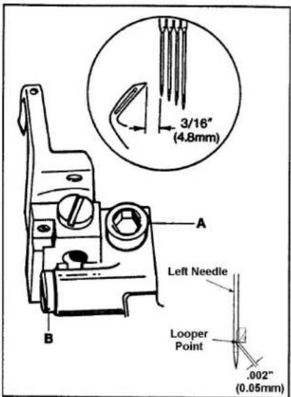
Turn the handwheel in operating direction until the looper has traveled fully to the left. Loosen screw (A, Fig. 15) and move the looper holder to the right or left until the distance from the point of the looper to the center of the first (left) needle is 3/16" (4.8mm). Clearance between the looper point and the scarf of the needle must not exceed .002" (0.05mm). Turn screw (B) until the .002" (0.05mm) dimension is achieved. Tighten screw (A).
For all styles except 36200UAK52 which is 1/8" (3.1mm).
NOTE: Looper gauge may need to be increased or decreased slightly to obtain a proper stitch.
SETTING THE FRONT NEEDLE GUARD
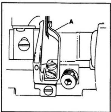
Install needle guard (A, Fig. 16) and position it to touch but not deflect the first needle. Slowly turn the handwheel in operating direction and check the needles to make sure they are not pinched between the looper and the needle guard.
NOTE: On machine style 36200UAK52 may deflect slightly
natural_image
Technical line drawing of a mechanical assembly with no visible text or symbolsFIG. 16
SETTING THE FEED DOGS
Preliminary Setting:
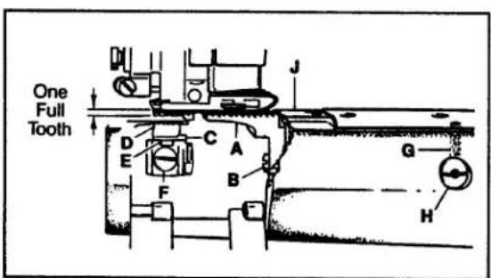
Install the differential feed dog (A, Fig. 17) with screw (B). Attach rear needle guard (C) to main feed dog (D), pushing in fully to the rear and tighten screw (E). Install main feed dog with screw (F).
As a starting point loosen screw (G) and set the slot in feed bar eccentric stud (H) in a horizontal position. Tighten screw (G). At the highest point of travel feed dogs (A and D) should be the depth of one full tooth above throat plate (J). Loosen screws (B and F) and adjust the height of each feed dog by moving them up or down in the elongated slot of the shank. Tighten screws (B and F). Loosen screw (G) and turn stud (H) until the top of the feed dogs are parallel to the throat plate. Rotating stud (H) will simultaneously level both feed dogs.
NOTE: When setting eccentric stud (H) if turned clockwise feeddogs should go up if turned counterclockwise feed dogs should go down.
text_image
One Full Tooth J D C A E F B G HFIG. 17
Final Setting:
Both the main and differential feed dogs may be individually adjusted to height. Main feed dog (D) at its highest position should rise above the top of the throat plate the depth of one full tooth when the normal presser spring pressure is applied. The differential feed (A) may then be raised to it.
SETTING THE REAR NEEDLE GUARD
text_image
A B C .000" - TouchFIG. 18
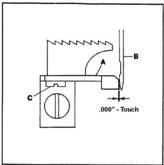
Set rear needle guard (A, Fig. 18) so it touches the first (left) needle (B) but does not deflect. Check the guard position to the other needles to avoid pinching. Loosen screw (C) and reposition guard (A) as necessary. Tighten screw (C).
SETTING THE STITCH LENGTH
This machine is designed to sew 10 to 16 stitches per inch. The normal factory setting is 12 stitches per inch. To change the stitch length remove the plug screw located directly above the cylinder side cover. Loosen screw (A, Fig. 19) in lever (B) and move up to increase the stitch length or down to decrease the stitch length. Tighten screw (A) and replace the plug screw.
CAUTION: If the stitch length is changed the rear needle guard setting must be checked and readjusted if necessary. Failure to do so may result in needle and/or parts breakage.
CAUTION: When making stitch length adjustment do not exceed maximum recommended stitch length due to possible part damage.

text_image
Technical diagram of a car dashboard with labeled parts A, B, C, D and a dial indicatorFIG. 19
DIFFERENTIAL FEED CONTROL
The amount of differential feed is controlled by lever (C, Fig. 19). The adjusting plate is numbered from 1 to 9. When the lever is set from numbers 1 to 4 reverse differential or stretching occurs. The numbers from 4 to 5 produce equal feed stitching while numbers 5 to 9 produce a gathering stitch. The two stop screws (D) can be set to limit the movement of lever (C) or lock the lever in one position.
text_image
1/32" (.8mm) B E C D AFIG. 20
SETTING THE PRESSER FOOT
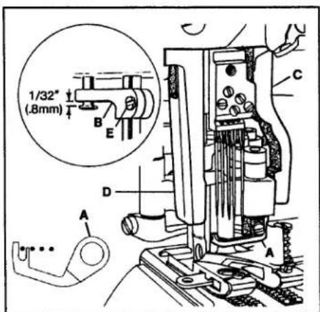
Remove the presser bar regulating screw and the presser spring. Raise the needle bar to its highest position and remove the retainer. As the foot is slipped under the needles, swing the upper knife into the opening on the right side of the foot and slide the linkage onto the hook driving sleeve. Insert the presser bar through the linkage and into the presser foot shank. Tighten presser foot screw. With the presser bar inserted properly into the presser foot, position the foot left to right so the finger of cover thread carrier (A, Fig. 20) is between the first and second needles. Set presser bar guide (B, Fig. 20 Inset) so foot will not move. Set right presser foot guide (C) and left presser foot guide (D) to maintain setting. Loosen presser bar guide screw (E Fig. 20 Inset) and check to see that foot has vertical freedom with no right to left play, no bind. Put the needle bar is in its lowest position, and set 1/32"(0.8mm) above head of presser bar guide stud. Tighten presser bar guide screw (E).
SETTING THE PRESSER FOOT (CONT.)
text_image
C A D 1/64" (-.4mm) B F 1/64" (-.4mm) EFIG. 21
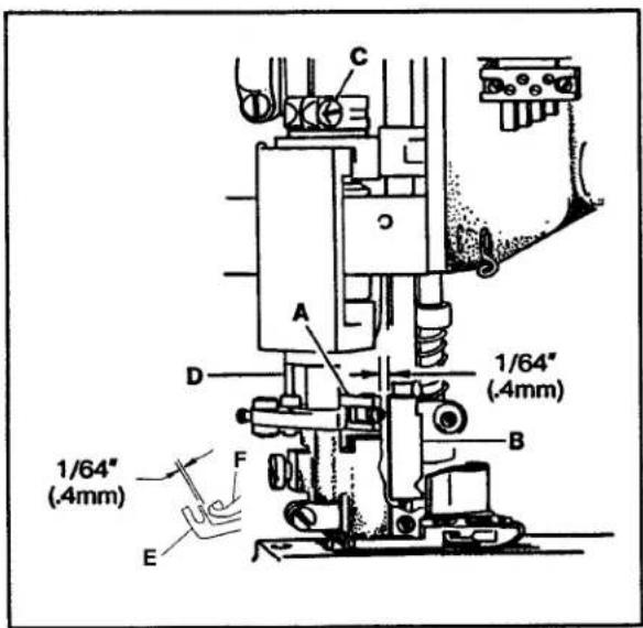
Turn the handwheel in operating direction until link (A, Fig. 20) has traveled fully to the front. There must be a 1/64" (0.4mm) clearance between link (A) and the back of needle head (B) when link (A) starts to jackknife. Loosen screw (C) and rotate driving sleeve (D) to position link (A). Tighten screw (C).
Add the cover thread hook(F) and cover thread carrier(E) if they are not in place. Position carrier so the thread loop will be carried behind the first two needles. There should be a minimum 1/64"(0.4mm) clearance between the hook and the carrier at their closest position.
text_image
A B C D 1/32" (0.8mm)FIG. 22
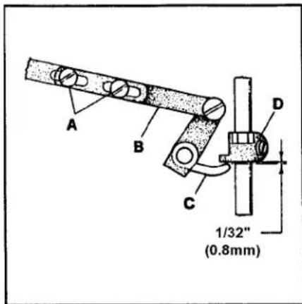
Replace the presser spring and the presser bar regulating screw. Loosen screws (A, Fig. 22) in lifter lever link assembly (B) and position lever (C) so there is 1/32" (0.8mm) clearance between it and presser bar guide (D) when the feed dogs are below the throat plate.

natural_image
Pure technical line drawing of a road intersection with no text, numbers, or symbolsFIG. 23
When the hook swings to the left it will pass over the cover thread. On its return travel, the thread will "pop" into the slot on the underside of the hook and is carried to the right. This thread forms a triangle for the third and forth needle threads to pass through. As the cover thread "pops" into the slot it must cast-off the high point of take-up (A, Fig. 23) at the same time. Loosen the two screws in the cover thread take-up and reposition if necessary. If there is difficulty in making this adjustment, check the thread tension and make sure the hook point has an extremely high polish and the angle is correct. Due to clearance requirements bending the hook is not recommended.
SETTING THE PRESSER FOOT (CONT.)
text_image
Technical diagram of a mechanical clamp or lever assembly with labeled parts A, B, and CFIG. 24
text_image
1/64" (.4mm)FIG. 25
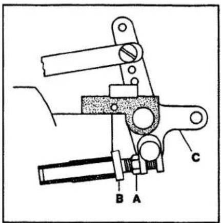
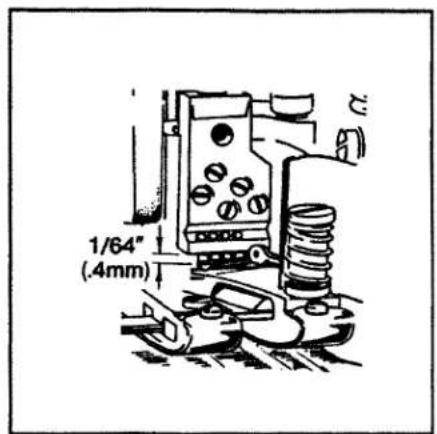
The presser foot lifter stop plunger must be set so the cover thread hook will not hit the bottom of the needle head as the presser foot is being lifted. Position the needle bar to its lowest point of travel. Loosen nut (A, Fig. 24) and turn plunger (B) clockwise until it strikes the crankshaft counterweight. While applying pressure to lifter (C) to lift the foot, back out of the plunger until the distance between the hook and the underside of the needle head is 1/64" (0.4mm) (see Fig. 25). Tighten nut (A, Fig. 24).
text_image
Technical diagram of a mechanical assembly with labeled parts A, B, C, DFIG. 26
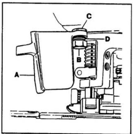
To adjust the position and tension of frame chip guard (A, Fig. 26), slightly loosen screw (B) and turn washer (C) with 21388Y spanner wrench until spring (D) snaps the guard into the closed position. Tighten screw (B). A light resistance should be felt when opening the guard.
SETTING THE KNIFE DRIVE LEVER
text_image
A B CFIG. 27
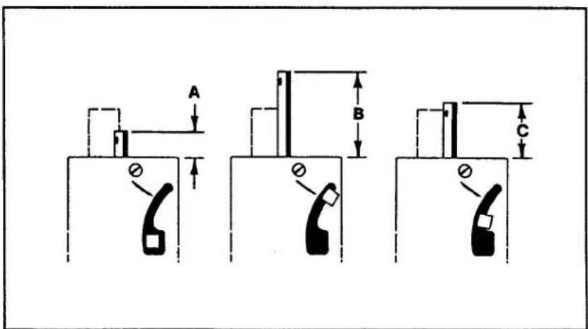
Position the needle bar at the bottom of its stroke. Measure from the top of the needle bar to the top of the casting to obtain dimension "A" (see Fig. 27).
Position the needle bar at the top of its stroke. Measure from the top of the needle bar to the top of the casting to obtain dimension "B". Subtract dimension "A" from dimension "B" and divide by two. Add this number to dimension "A" to obtain "C". Set a caliper to the "C" dimension and turn the handwheel in operating direction until the height of the needle bar is at the "C" dimension
SETTING THE KNIFE DRIVE LEVER (CONT.)
text_image
6 O'Clock 2 27/32" (72.2mm)FIG. 28
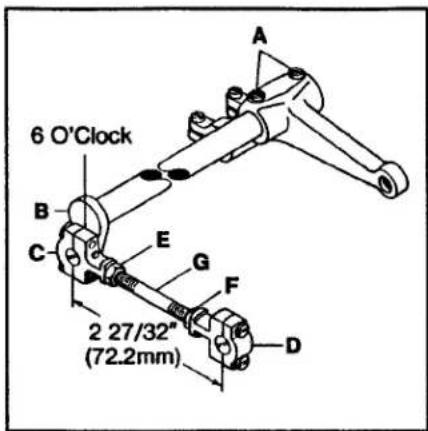
At this time the knife drive lever should be in the 6 o'clock position. If adjustment is necessary, loosen screws (A, Fig. 28) in the needle lever and reposition knife drive lever (B) to the 6 o'clock position. Tighten screws (A). The dimension between the centerline of right and left knife drive connection ball joints (C and D) must be 2 27/32" (72.2mm). Loosen left hand thread nut (E), right hand thread nut (F) and turn connecting rod (G) until dimension is achieved. Tighten nuts (E and F).
SETTING THE TRIMMING KNIVES FOR BUTT SEAMING (STYLES 36200UA52, UAE52, UAK52, UJ60, UJE60, UX52, UX60)
text_image
Butt Seam 1/32" - 1/16" (.8mm - 1.6mm) Lap Seam 1/64" (.4mm)FIG. 29
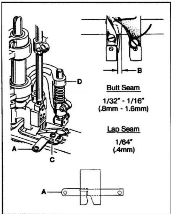
To make the adjustments for a flat, butt seam, position lower knife (A, Fig. 29) in the foot so it extends 1/32" to 1/16" (0.8mm to 1.6mm) past the right side of the left toe (B) (approximately between the second and third needles). Loosen screw (C) and move knife in or out as required. Tighten screw (C) securely.
SETTING THE TRIMMING KNIVES FOR LAP SEAMING (STYLES 36200UH52, UAE52, UE52, UE60, UJE60, UM60, UY52, UY60)
To make the adjustments for a lap seam, position lower knife (A, Fig. 29) in the foot so it extends 1/64" (0.4mm) past the right side of the left toe (B) (approximately even with the first needle). Loosen screw (C) and move knife in or out as required. Tighten screw (C) securely.
(ALL STYLES)
Turn handwheel in operating direction until knife driving bracket (D) is positioned to the extreme left. At this time the front edge of both knives should be parallel with each other and the upper knife cutting edge should overlap lower knife cutting edge by 1/64" (0.4mm)
SETTING THE TRIMMING KNIVES (ALL STYLES) (CONT.)
text_image
Technical diagram showing labeled mechanical components with annotations A, B, C, DFIG. 30
text_image
A C B 1/16" (1.6mm)FIG. 31
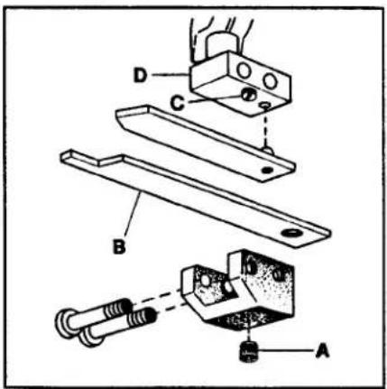
If necessary loosen screw (A, Fig. 30) and move knife (B) to the right or left as required. Tighten screw (A).
If the shear angle between the knives has to be changed, raise or lower screw (C, Fig. 30) in knife holder shank (D).
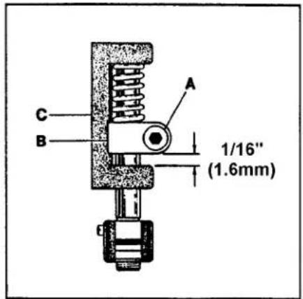
To set spring pressure between the knives loosen screw (A, Fig. 31) and raise knife holder guide collar (B) 1/8" (3.2mm) from knife driving bracket (C). Tighten screw (A).
text_image
Technical diagram of a mechanical device with labeled components A, B, and CFIG. 32
NOTE: More or less spring pressure may be required depending on the type of material being sewn. Also, both knives may have to be repositioned after a trial seam is made so there is an equal margin from the edges of the two plies to the center rows of stitching.
NEEDLE THREAD ADJUSTMENTS
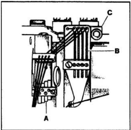
Four needle thread strike-off pins (A, Fig. 32) are provided for independent needle thread control. Level the take-ups to the height of the thread in the needle lever eyelet at its lowest position. Raise the first take-up (nearest the operator) 1/8" (3.2mm) and the second take-up 1/16" (1.6mm). Further adjustment may be necessary to obtain proper needle loop size so skipped stitches may be avoided.
text_image
1/8" (3.2mm) A B C DFIG. 33
Set the four frame needle thread eyelets (B, Fig. 32) eye with the eyelets in holder (C). Adjust as necessary so the needle thread loops around the looper will remain firm and not seek random positions when the needle bar descends.
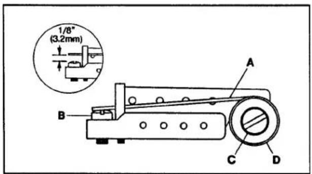
Unlocking spring (A, Fig. 33) provides a proportional amount of pull-up of the needle threads when the machine is reversed for unlocking the stitch so the loops will not form on the front of the needles and become caught by the looper.
NOTE: Unlocking spring is only used when starting and stopping on the material.
Turn screw (B) up or down so unlocking spring (A) will have 1/8" (3.2mm) drop from the bottom of the thread holes to the top of screw (B). Loosen screw (C) and turn knurled knob (D) to adjust the spring tension. Tighten screw (C).
Tension of the six threads is individually controlled. The needle tension is seldom uniform; the first needle thread having more tension than the other three. Use only enough tension to pull up the stitch. A well-balanced stitch will have the first and fourth needle loops pulled up and the second and third needle loops small and even.
LOOPER THREAD ADJUSTMENT
text_image
Technical diagram of a mechanical component with labeled parts A, B, C, D, E and F, showing assembly or assembly details.FIG. 34
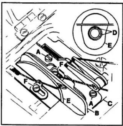
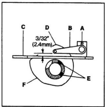
Loosen screws (A, Fig. 34) and position looper thread cast-off (B) flush with the right end of cast-off support plate (C). Tighten screws (A). Loosen screws (D, Fig. 34 inset) and time take-up (E) so the thread will cast-off when the needle bar has descended 7/64" (2.8mm) from its highest position. When thread eyelets (F) are moved further to the left the amount of thread pull-off will increase.
text_image
C D B A 3/32" (2.4mm) F EFIG. 35
COVER THREAD ADJUSTMENT
Loosen screw (A, Fig. 35) and set the lower edge of cover thread take-up eyelet (B) so its 3/32" (2.4mm) above the surface of cast-off plate (C). Tighten screw (A). As the cover thread hook moves to the left over the cover thread and the needle bar starts to rise, the cover thread must "cast-off" from the high point of take-up (D). Loosen screws (E) and adjust take-up (F) accordingly. make sure that take-up (F) is centered in cast-off plate slot (C) and take-up eyelet (B) is centered to take-up (F). Tighten screws (E).
text_image
Technical diagram of a mechanical device with labeled parts A, B, and D, showing internal components and assembly.FIG. 36
TENSIONRELEASE
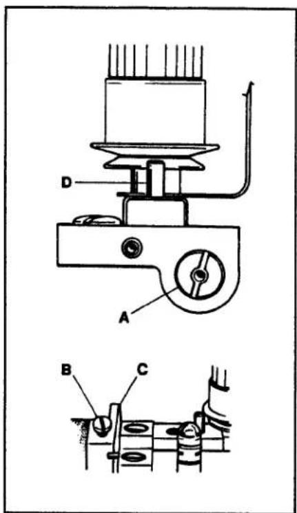
The tension releases should start to function when the presser foot has raised approximately 1/32" (0.8mm) above the surface of the throat plate and be entirely released when the presser foot has reached its highest position. Insert a large screwdriver into slot on the right end of shaft (A, Fig. 36), loosen screw (B) in lifter lever (C) and turn the screwdriver to raise or lower pins (D). Tighten screw (B).
NOTE: Make sure the 1/32" (0.8mm) clearance between the presser bar lifter lever and presser bar guide has been maintained. Refer to Fig. 22 if readjustment is necessary.
HUNG FOOT ADJUSTMENT
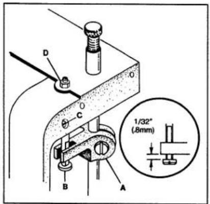
When sewing on extremely lightweight material and/or feed cutting is a problem, the presser foot may be "hung" by raising stud (B) until guide (A) rests on the shoulder of stud (B). This adjustment will raise the presser foot slightly, so only the pressure of the presser foot shoes contact the material. Turn handwheel in operating direction until the feed dogs are below the throat plate surface. At this time there should be a 1/32" (0.8mm) clearance between the bottom of presser bar guide (A, Fig. 37A&B) and presser bar guide stud (B). On 36200UY52&UY60 to hang presser foot, loosen lock nut (C Fig. 37A) and turn thumbscrew (D Fig. 37A) so that the foot comes up slightly, tighten nut (C Fig. 37A). On all other 36200 machines loosen screw (C Fig. 37B) and turn nut (D Fig. 37B) so that foot comes up slightly, tighten screw (C Fig. 37B).
SETTING THE LAP FORMER
(STYLES 36200UAE52, UE52, UE60, UH52, UJE60, UM60, UY52, UY60)
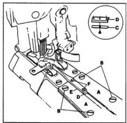
Attach gibs (A, Fig. 38) to the cylinder cover but do not tighten screws (B); leave them snug for further adjustment. Fasten spring (C, Fig. 38 inset) to the bottom of slide block (D) and insert between gibs (A). Attach lap former (E) to slide block (D) with screws (F) and position it in the center of the presser foot. Position the slide block so it has a snug (but not tight) fit the entire length of the gibs. Tighten screws (B).

text_image
D C 0 B A 1/32" (8mm)FIG. 37A
text_image
D O C B A 1/32" (8mm)FIG. 37B
text_image
Technical diagram of a sewing machine with labeled parts and a magnified inset showing component labels A, B, C, D, E, F.FIG. 38
LAP SEAMING
Lap Seaming on the 36200UAE52, UE52, UE60, UJE60, UY52, UY60 can be accomplished using three methods:
- Lap Seaming cutting two plies of material.
A. Remove butt seam presser foot and replace with lap seam presser foot. Refer to pages 15, 16, & 17 for presser foot adjustments.
B. Attach lap former and slide block with spring. See above for adjustments.
- Lap seaming cutting only right ply of material.
A. Use butt seam presser foot.
B. Remove front right throat plate screw and attach 36203 edge guide with 22849 screw, and adjust left or right for proper coverage on bottom.
C. Adjust knives left or right for proper trimming and coverage on top.
- Lap seaming cutting only left ply of material.
A. Use butt seam presser foot.
B. Remove left front throat plate screw and attach 36203 edge guide with 22849 screw, and adjust left or right for proper coverage on bottom.
C. Adjust knives left or right for proper trimming and coverage on top.
| ELYTSENIHCAM | GNIMAESTTUBTOOFF | GNIMAROFCUTTING TWO PLIES |
| 36200UAE52 | 36220A | 36220E |
| 36 6E200 | 36220K | 36220W |
ESPAL TOOFRESSERP
text_image
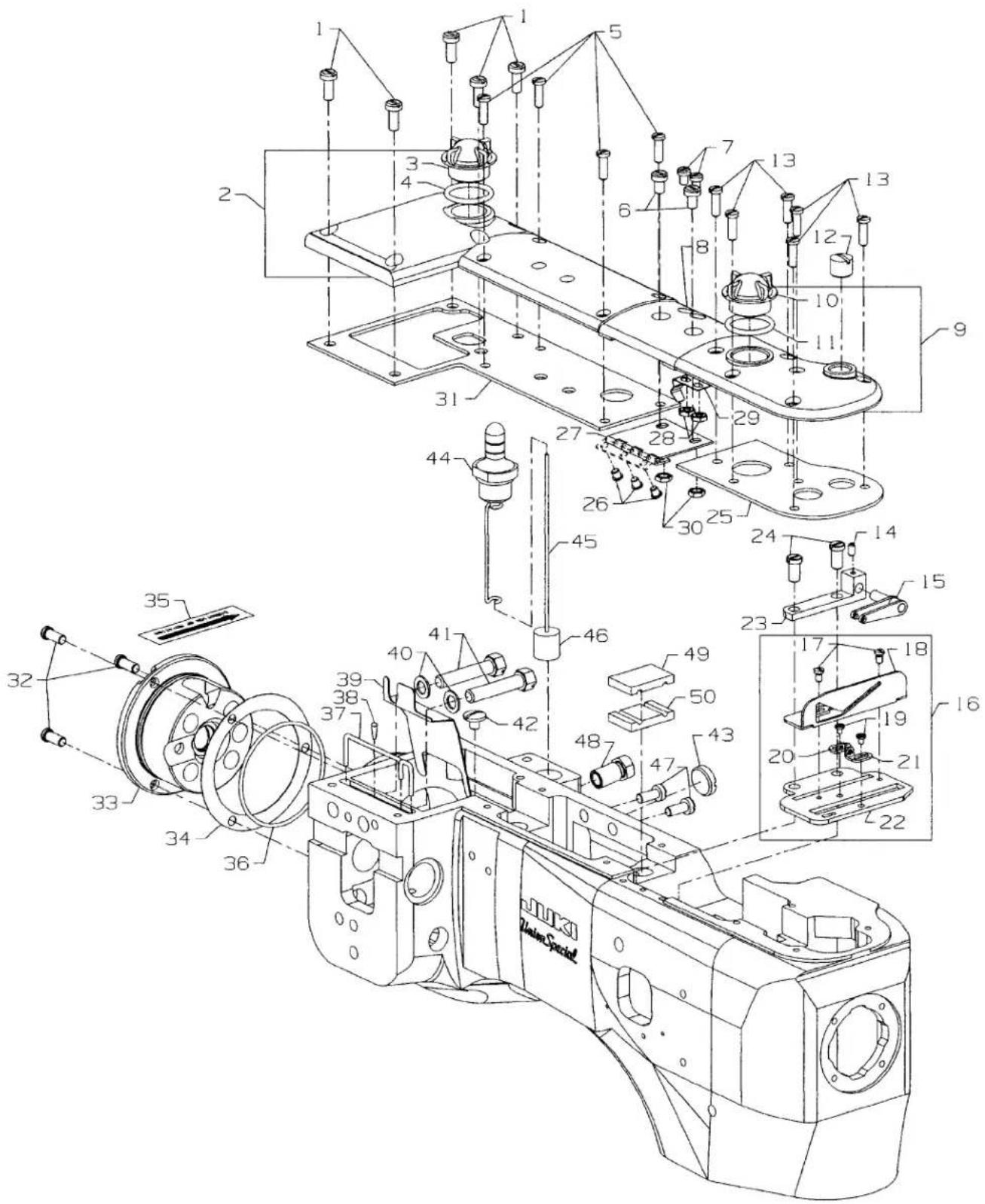
Technical diagram of a mechanical assembly with numbered components and exploded views, including a detailed view of the motor.OIL SIGHT GAUGES, TOP COVERS & MISCELLANEOUS TAKEUP & EYELET PARTS
| Ref. | Amt. | ||
| No. | Part No. | Description | Req. |
- 93 Screw, for crank chamber cover 5
- 35888N Crank Chamber Cover 1
- B3530555000 Oil Sight Gauge 1
- 660-212 "O"Ring 1
- 22516A Screw 4
- 93A Screw, for middle top cover 2
- 90 Screw, for spring 2
- 35887X Top Cover, middle 1
- 35887AE Top Cover, front 1
- B3530555000 Oil Sight Gauge 1
- 660-212 "O"Ring 1
- 22539M Plug Screw 1
- 22516A Screw, for front top cover 6
- 73C Screw 1
- 36256 Cover Thread Take-up Eyelet 1
- 29476XC Cast-Off Plate Assembly 1
- 22KH Screw, for cast-off 2
- 36204 Cast-off 1
- 73A Screw, for cast-off plate eyelets 2
- 52958F Cast-off Plate Eyelet, rear 1
- 52958C Cast-off Plate Eyelet, front 1
- 36204A Cast-off Plate 1
- 36256A Cover Thread Take-up Eyelet Holder 1
- 22839 Screw 2
- 35887AG Gasket, for front top cover 1
- 22564B Screw, for middle cover hinge 3
- 35887R Middle Cover Hinge 1
- 41071G Nut, for top middle cover spring screw 2
- 35887M Spring, for middle top cover 1
- 12934A Nut, for top middle cover spring screw 2
- 35888T Gasket, for crank chamber 1
- 22569B Screw, for bushing housing 1
- 36290D Bushing Housing, includes bushing 1
- 56390E Gasket, for bushing housing 1
- LA528 Directional Label 1
- 660-935 "O"Ring 1
- CL21 Oil Wick 1
- CO67E Cork 1
- 35889H Oil Shield 1
- 6042A Washer, for screw 2
- 22759A Screw, for connecting head to main frame 2
- 22711 Screw, for oil wick 1
- 22539AA Plug Screw 1
- 36293B Oil Sight Gauge 1
- 36293E Oil Level Indicator 1
- 39593C Oil Gauge Float 1
- 93 Screw, for oil pump housing 2
- 35890P Bushing 1
- 35893G Seal, Upper 1
- 35893H Seal, Lower 1
text_image
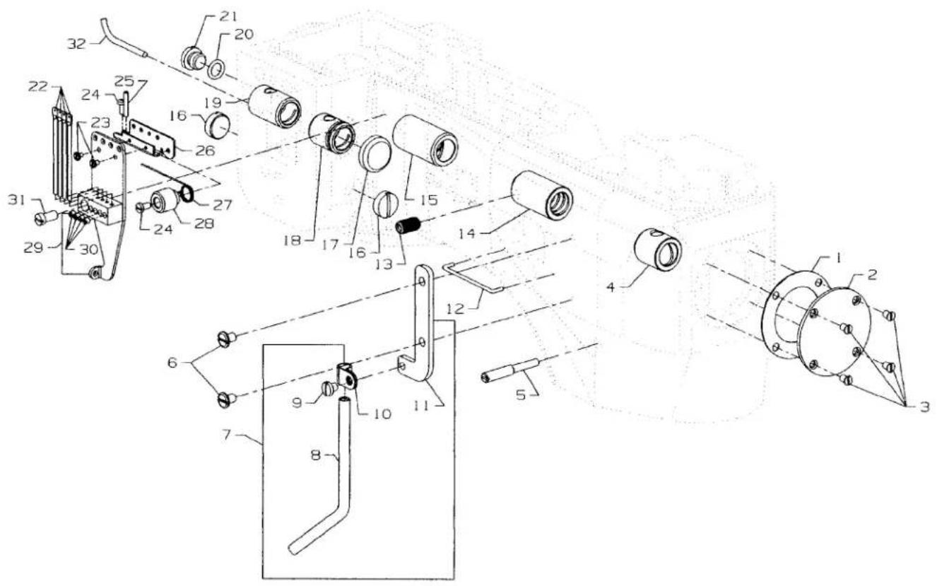
Technical diagram of a mechanical assembly with numbered components and exploded view, likely for assembly or manufacturing purposes.MAIN FRAME, BUSHINGS & MISCELLANEOUS EYELET & COVER PARTS
| Ref. | Amt. | ||
| No. | Part No. | Description | Req. |
- 35887AF Gasket, end cover .... 1
- 35887Z End Cover 1
- 22564B Screw, end cover 4
- 36290B Main Shaft Bushing, front 1
- 22791D Screw, for looper drive lever shaft 1
- 22829 Screw, looper thread shield 2
- 29105BH Looper Thread Shield 1
- 35866A Tube 1
- SS7110510SP Screw 1
- 35866B Tube Clamp 1
- 35883AL Support 1
- 35781D Looper Thread Guide Wire 1
- 62271B Thread Guide 1
- 36290A Main Shaft Bushing, rear 1
- 35890E Crankshaft Bushing, front 1
- 22539T Plug Screw 2
- 35761D Bushing Cap 1
- 35860D Needle Lever Shaft Bushing, front 1
- 36260A Needle Lever Shaft Bushing, rear 1
- 660-206 Rubber "O" Ring 1
- 22733B Oil Drain Screw 1
- 36271A Frame Needle Thread Eyelet 4
- 73A Screw, for needle thread eyelet 2
- 22768B Screw, for unlocking spring height adjusting 1
- 22799B Screw 2
- 36271G Stitch Unlocker Mounting Bracket 1
- 36271E Unlocking Spring 1
- 36271H Spring Holder 1
- 36271 Needle Thread Eyelet 1
- 28C Screw 4
- 22569D Screw, for needle thread eyelet 1
- CL21 Oil Wick 1
text_image
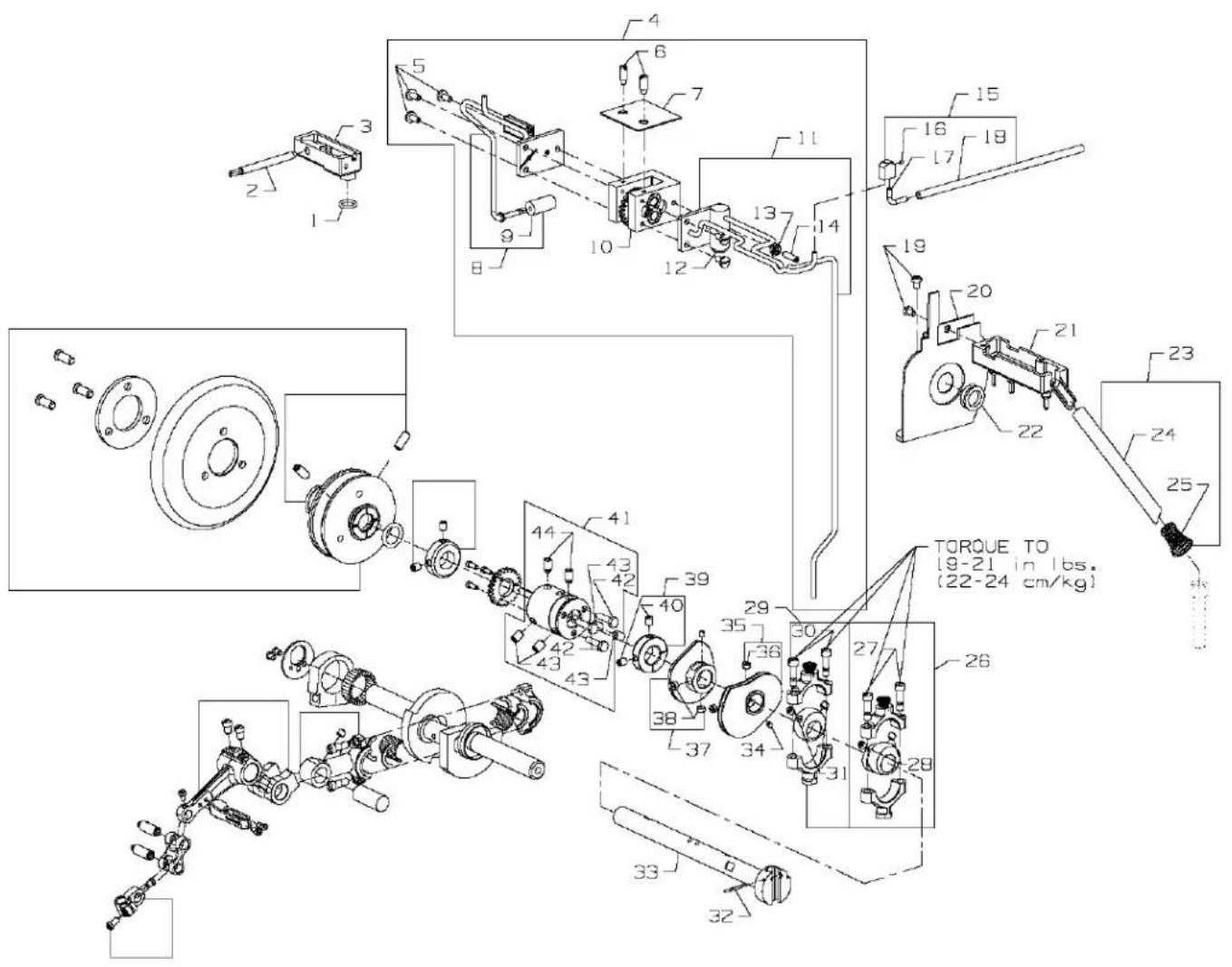
Technical diagram of a mechanical assembly with numbered components and torque specifications in ChineseMAIN SHAFT & MISCELLANEOUS OILING
| Ref. | Amt. | ||
| No. | Part No. | Description | Req. |
- 660-207 Oil Seal Ring 1
- 35897BU Reservoir Outlet Tube 1
- 35894J Oil Reservoir, back 1
- 29472Y Pump Assembly 1
- 22585A Screw, for housing cover 5
- 21756G Vent Screw 2
- 35897BW Gasket 1
- 36297J Housing Cover and Oil Tube, rear 1
- 35897BV Intake Filter 1
- 29472AC Pump Body and Gear Assembly 1
- 36297M Housing Cover and Oil Tube, front 1
- 22571B Plug Screw 1
- 41071G Nut 1
- 22565A Screw 1
- 36293M Oil Splitter 1
- 1096 Screw 1
- 36293L Oil Tube 1
- 50393-140 Tubing 1
- 90 Screw, for take-up shield 2
- 36261A Take-up Shield Assembly 1
- 35894L Oil Reservoir, front 1
- 666-338 Oil Seal Ring 1
- 36293K Oil Tube Bypass 1
- 671B3 Air Tube 1
- 11550209 Tension Spring 1
- 29101J Feed Drive Eccentric Assembly 1
- 22587E Screw 2
- 22894W Set Screw 2
- 29103T Feed Lift Eccentric Assembly 1
- 22587E Screw 2
- 22894W Set Screw 2
- 660-219P Roll Pin 1
- 36222C Main Shaft 1
- 22801 Screw 2
- 36223 Double Disc Take-up 1
- 22580 Screw 2
- 36223A Cover Thread Take-up 1
- 22580 Screw 2
- 35895Y Crankshaft Thrust Collar 1
- 22894AM Screw 2
- 35895X Main Shaft Coupling 1
- 22519F Screw 3
- 22894J Set Screw 4
- 22894K Spot Screw 2
text_image
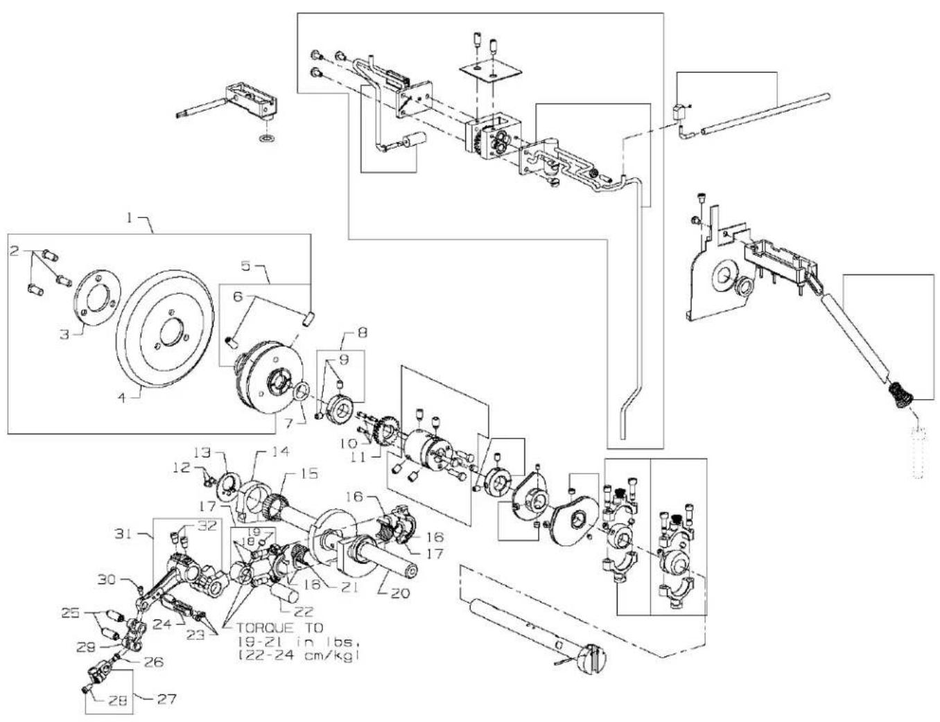
Technical schematic diagram of a mechanical assembly with numbered components and torque specifications in ChineseCRANKSHAFT & NEEDLE LEVER PARTS
| Ref. | Amt. | ||
| No. | Part No. | Description | Req. |
- 36221K Pulley Assembly I1
- 22574 Screw 3
- 61321L Clamp Plate 1
- 61321J Handwheel 1
- 36221D Pulley 1
- 22894E Screw, for adjustable pulley 2
- 660-202 Oil Seal Ring 1
- 35895Y Crankshaft Thrust Collar 1
- 22894AM Screw 2
- 22797 Screw 3
- 35897BY Pump Driving Gear 1
- 22766 Screw 2
- 36251N Needle Bearing Retaining Plate 1
- 36251M Eccentric Bearing 1
- 36263 Needle Bearing Rollers 28
- 35763G Needle Bearing Retaining Ring 4
- 35862A Needle Lever Connecting Rod 1
- 22587B Screw 2
- 22894W Screw 1
- 36222A Crankshaft 1
- 35763F Needle Bearing Rollers 28
- 35847X Needle Lever Connecting Rod Pin 1
- 77 Screw 2
- 36264D Needle Lever Thread Eyelet 1
- 51054A Link Pin 2
- 22564 Screw 1
- 51254K Needle Bar Connection .... 1
- 22562A Screw 1
- 56354D Needle Bar Link 1
- 77 Screw 1
- 35815C Needle Lever 1
- 22596B Screw 2
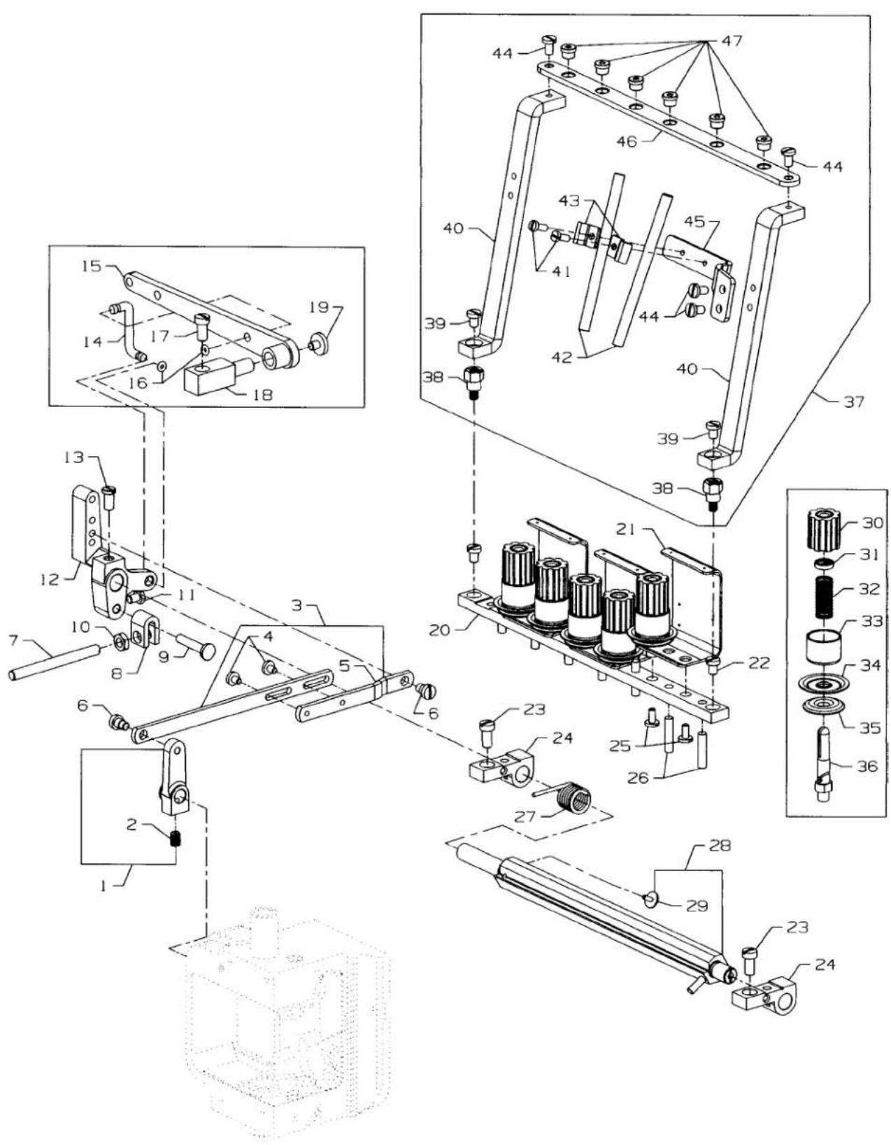
text_image
Technical schematic diagram of a mechanical assembly with numbered components and exploded viewsTENSION PARTS
| Ref. | Amt. | ||
| No. | Part No. | Description | Req. |
- 35880M Lift Lever Link Connection .... 1
- 22894J Screw 1
- 36280V Lifter Lever Link Assembly 1
- 22585C Screw 2
- 36280U Lifter Lever Link 1
- 86 Screw 2
- 36280A Presser Foot Lifter Stop Plunger 1
- 36280C Stop Plunger Segment 1
- 36280D Stop Plunger Segment Pin 1
- 258A Nut 1
- 22519 Screw, for stop plunger segment pin .... 1
- 36280W Presser Bar Lifter Lever 1
- 22839D Screw 1
- 36280T Lifter Lever Connecting Link 1
- 36280S Presser Foot Connection Lifter Lever 1
- 660-254C Retaining Ring 2
- 22517 Screw, for presser foot lifter bearing bracket 1
- 36280N Presser Foot Lifter Bearing Bracket 1
- 255 Screw 1
- 36298H Tension Support 1
- 36298G Tension Thread Eyelet 3
- 94 Screw, for tension support 2
- 22517 Screw, for tension plate bracket 2
- 36292M Tension Plate Bracket 2
- 22585A Screw, for tension post 6
- 35792T Tension Disc Release Pin 7
- 36292K Spring, for tension release shaft 1
- 36292N Tension Release Shaft 1
- 22784F Screw 1
- C50092S Tension Nut 6
- 39592AK Tension Spring Ferrule 6
- 51292F-2 Tension Spring, for cover thread 1
- 51292F-4 Tension Spring, for looper thread .... 1
- 51292F-5 Tension Spring, for needle thread 4
- W56392F Shield, for tension spring 6
- 35792 Tension Disc, large 6
- 109 Tension Disc, small 6
- 36292Q Tension Post 6
- 36266A Thread Guide Assembly 1
- 22894BK Screw Post 1
- 94 Screw 2
- 36283R Mounting Bracket 2
- SS7090910TP Screw 2
- 36266 Eyelet Tube 2
- 36283U Eyelet Tube Holder 2
- SS7110840SP Screw 4
- 36283T Bracket, Tube 1
- 36283S Eyelet Plate 1
- B3319704L00 Eyelet 6
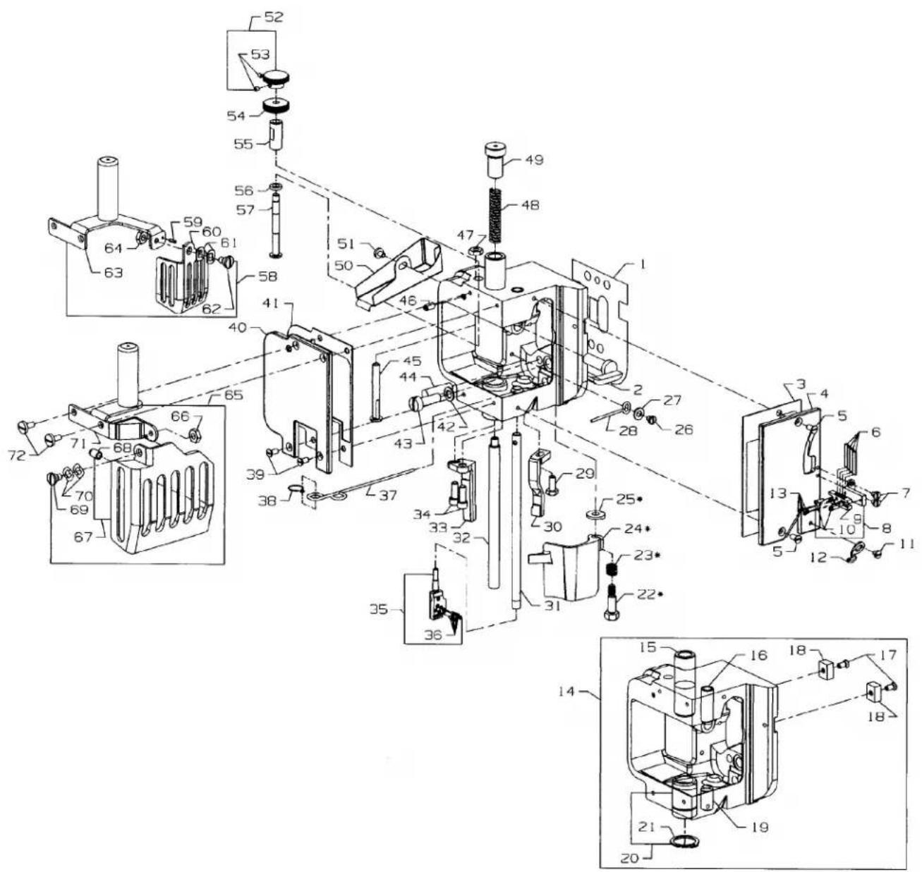
text_image
Technical schematic diagram of a mechanical assembly with numbered components and exploded views- Items 22, 23, 24, 25, and spanner wrench 21388Y are all part of kit 29480AZJ
DETACHABLE HEAD, HEAD COVERS, NEEDLE BAR & NEEDLE BAR HEAD
| Ref. No. | Part No. | Description | Amt. Req. |
| 1. | 36289B | Baffle Plate | 1 |
| 2. | 36280J | Presser Bar Lifter Lever | 1 |
| 3. | 36289H | Gasket, for front head cover | 1 |
| 4. | 36289 | Head Cover, front | 1 |
| 5. | 22524 | Screw, for front head cover | 2 |
| 6. | 36264B | Needle Thread Strike-off Pin | 4 |
| 7. | 28 | Screw, for needle thread take-up | 2 |
| 8. | 36264E | Needle Thread Take-up, complete | 1 |
| 9. | 36264F | Strike-off Pin Holder | 1 |
| 10. | 22738C | Screw, for needle thread take-up | 2 |
| 11. | 28 | Screw, for cover thread eyelet | 1 |
| 12. | 51259 | Cover Thread Eyelet, for all styles except 36200UX52, UX60 | 1 |
| 13. | 28A | Screw, for needle thread take-up | 4 |
| 14. | 36229B | Detachable Sewing Head | 1 |
| - | 36229F | Detachable Sewing Head, for styles 36200UY52, UY60 | 1 |
| 15. | 36278A | Presser Bar Bushing | 1 |
| 16. | 35859D | Needle Bar Bushing, upper | 1 |
| 17. | 22524 | Screw | 2 |
| 18. | 35767 | Sewing Head Key | 2 |
| 19. | 35859J | Needle Bar Bushing, lower | 1 |
| 20. | 36251D | Cover Thread Carrier and Hook Driving Sleeve Bushing | 1 |
| 21. | 660-261 | Retaining Ring | 1 |
| 22. | 22777B | Screw, for frame chip guard | 1 |
| 23. | 36279L | Spring, for frame chip guard, for all styles except 36200UX52, UX60 | 1 |
| - | 36279B | Spring, for frame chip guard, for styles 36200UX52, UX60 | 1 |
| 24. | 36279N | Frame Chip Guard, for all styles except 36200UX52, UX60 | 1 |
| 25. | 36279M | Washer, for frame chip guard, for all styles except 36200UX52, UX60 | 1 |
| - | 36279A | Washer, for frame chip guard, for styles 36200UX52, UX60 | 1 |
| 26. | 22513 | Screw, for oil deflector | 1 |
| 27. | 8372A | Washer | 1 |
| 28. | 36294C | Oil Deflector | 1 |
| 29. | 22881A | Screw, for right presser foot guide | 1 |
| 30. | 36278K | Presser Foot Guide, right | 1 |
| - | 36278S | Presser Foot Guide, right, for styles 36200UY52, UY60 | 1 |
| 31. | 35817E | Needle Bar | 1 |
| 32. | 36278 | Presser Bar | 1 |
- thru 72. See Following page
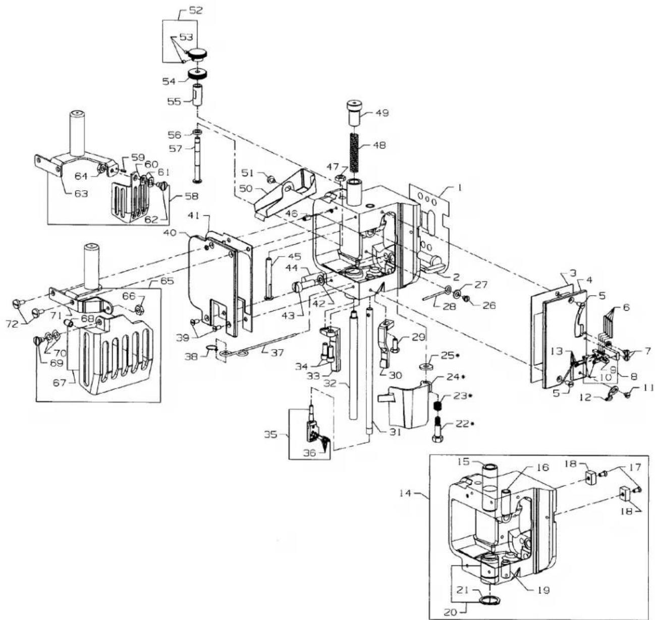
text_image
Technical schematic diagram of a mechanical assembly with numbered components and exploded views- Items 22, 23, 24, 25, and spanner wrench 21388Y are all part of kit 29480AZJ
DETACHABLE HEAD, HEAD COVERS, NEEDLE BAR & NEEDLE BAR HEAD
| Ref. | Amt. | ||
| No. | Part No. | Description | Req. |
- thru 32. See Preceding page
| 33. | 36278L | Presser Foot Guide, left | 1 |
| - | 36278R | Presser Foot Guide, left, for styles 36200UY52, UY60 | 1 |
| 34. | 22653B-8 | Screw, for left presser foot guide | 2 |
| 35. | 36218 | Needle Head, for styles36200UA52, UAE52, UE52, UAK52, UH52, UX52, UY52 | 1 |
| - | 36218J | Needle Head, for styles36200UE60, UJ60, UJE60, UM60, UX60, UY60 | 1 |
| 36. | 22738H | Screw, for needles and retainer | 5 |
| 37. | CQ200000000 | Yarn, Oil Wick | 1 |
| 38. | 35897CK | Oil Wick Hook | 1 |
| 39. | 22524 | Screw, for left head cover | 2 |
| 40. | 36289A | Head Cover, left | 1 |
| 41. | 36289J | Gasket, for left head cover | 1 |
| 42. | 6042A | Washer | 1 |
| 43. | 318 | Screw, for connecting head to main frame | 1 |
| 44. | 664F-16 | Taper Pin | 1 |
| 45. | 36278H | Presser Bar Guide Stud | 1 |
| 46. | 22560A | Screw, for presser bar guide stud | 1 |
| 47. | 12538 | Nut, for presser bar guide stud | 1 |
| 48. | 36278F | Spring, for presser bar | 1 |
| - | 36278U | Spring, for presser bar, for styles 36200UY52, UY60 | 1 |
| 49. | 36278M | Presser Bar Regulating Screw | 1 |
| 50. | 36294B | Lifter Lever Link Connection | 1 |
| 51. | 22585C | Screw | 1 |
| 52. | 660-1131 | Knurled Knob, for styles 36200UY52, UY60 | 1 |
| 53. | 28C | Screw | 2 |
| 54. | 660-1130 | Knurled Nut, for styles 36200UY52, UY60 | 1 |
| 55. | 36290E | Threaded Sleve, for Hanging Foot, for styles 36200UY52, UY60 | 1 |
| 56. | 36237M | Collar Bumper, for styles 36200UY52, UY60 | 1 |
| 57. | 36278T | Screw Stud, for Hanging Foot, for styles 36200UY52, UY60 | 1 |
| 58. | 29476YN | Sewing Guard Assembly, for style 36200UX52 | 1 |
| 59. | PS0200062KH | Roll Pin | 1 |
| 60. | 36296C | Sewing Guard | 1 |
| 61. | WZ0641510KP | Spring Washer | 2 |
| 62. | 22758E | Screw | 1 |
| 63. | 36283M | Mounting Bracket | 1 |
| 64. | 9937 | Nut | 1 |
| 65. | 29476YP | Sewing Guard Assembly, for all styles except 36200UX52 | 1 |
| 66. | 9937 | Nut | 1 |
| 67. | 35896D | Sewing Guard | 1 |
| 68. | 666-340A | Bumper Plug | 1 |
| 69. | 22758E | Screw | 1 |
| 70. | WZ0641510KP | Spring Washer | 2 |
| 71. | 36283P | Mounting Bracket | 1 |
| 72. | 22585B | Screw | 2 |
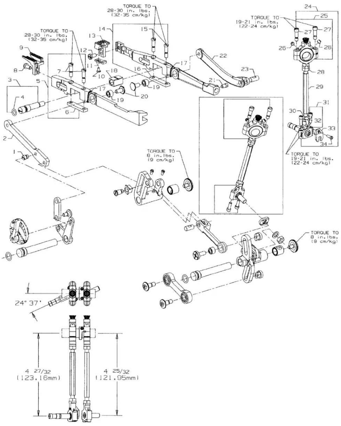
text_image
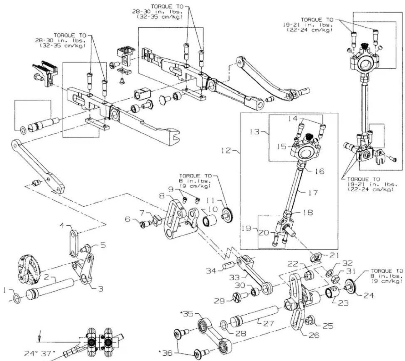
TORQUE TO 28-30 in. lbs. (32-35 cm/kg) TORQUE TO 28-30 in. lbs. (32-35 cm/kg) TORQUE TO 8 in. lbs. (9 cm/kg) TORQUE TO 19-21 in. lbs. (22-24 cm/kg) TORQUE TO 19-21 in. lbs. (22-24 cm/kg) TORQUE TO 8 in. lbs. (9 cm/kg) 24° 37' 4 27/32 (123.16mm) 4 25/32 (121.95mm)DIFFERENTIAL & MAIN FEED BARS, FEED DOGS & FEED LIFT ECCENTRIC ASSEMBLY
| Ref. | Amt. | ||
| No. | Part No. | Description | Req. |
- 22845M Screw, for differential feed bar driving link.... 1
- 36236F Differential Feed Bar Driving Link 1
- 36234M Feed Bar Eccentric Stud 1
- 660-220 "O"Ring 1
- 36234F Differential Feed Bar 1
- 36234G Feed Bar Plate 1
- 22587H Screw 2
- 22528 Screw, for differential feed dog 1
- 36226A Differential Feed Dog, marked "FV", 14 teeth per inch, for Styles 36200UA52, UAE52, UAK52, UE52, UE60, UJ60, UJE60, UX52, UX60.... 1
- 36226B Differential Feed Dog, marked "PB", 16 teeth per inch .... 1
- 36226K Differential Feed Dog, 16 teeth per inch, for styles 36200UY52, UY60 .... 1
- 36226H Differential Feed Dog, marked "PQ", 14 teeth per inch, .050" (1.27mm) step on right side, for styles 36200UH52.... 1
- 36226J Differential Feed Dog, marked "VU", 16 teeth per inch, .050" (1.27mm) step on right side, for styles 36200UM60.... 1
- 87U Screw, for needle guard .... 1
- 36225 Needle Guard all styles except 36200UAK52.... 1
- 36225A Needle Guard for style 36200UAK52 1
- 22528 Screw, for main feed dog .... 1
- 36205A Main Feed Dog, marked "PK", 14 teeth per inch, for Styles 36200UA52, UAE52, UAK52, UE52, UE60, UJ60, UJE60, UX52, UX60.... 1
- 36205B Main Feed Dog, marked "PL", 16 teeth per inch .... 1
- 36205N Main Feed Dog, 16 teeth per inch, for styles 36200UY52, UY60 .... 1
- 36205H Main Feed Dog, marked "PR", 14 teeth per inch, .050" (1.27mm) step on right side, for styles 36200UH52.... 1
- 36205J Main Feed Dog, marked "VV", 16 teeth per inch, .050" (1.27mm) step on right side, for styles 36200UM60.... 1
- 36234E Main Feed Bar 1
- 22578H Screw 2
- 36234G Feed Bar Plate 1
- CQ00000000 Yarn 2
- 36234C Feed Bar Slide Block 1
- 36236H Bushing 2
- 36236G Driving Link Stud 2
- 33174B Screw 1
- 36236E Main Feed Bar Drive Link 1
- 62238A Link Pin 1
- 29478CS Feed Lift Eccentric Assembly 1
- 29103T Feed Lift Eccentric Assembly Ball Joint 1
- 22894W Set Screw 2
- 22587E Screw 2
- 269 Nut, left thread 1
- 36244 Connecting Rod 1
- 18 Nut, right thread .... 1
- 36244A Ball Joint, complete 1
- 22729C Screw 2
- 41255B Ball Fork 1
- 22747 Screw, for ball fork 1
text_image
TORQUE TO 28-30 in. lbs. (32-35 cm/kg) TORQUE TO 28-30 in. lbs. (32-35 cm/kg) TORQUE TO 19-21 in. lbs. (22-24 cm/kg) TORQUE TO 19-21 in. lbs. (22-24 cm/kg) TORQUE TO 8 in. lbs. (9 cm/kg) TORQUE TO 8 in. lbs. (9 cm/kg) TORQUE TO 19-21 in. lbs. (22-24 cm/kg) TORQUE TO 8 in. lbs. (9 cm/kg) 24° 37' *35 28 27 26 25 24 23 22 21 19 18 17 16 15 14 13 12 11 10 9 8 7 6 5 4 3 2 1* Items 35 and 36 may also be purchased as 29478FI
text_image
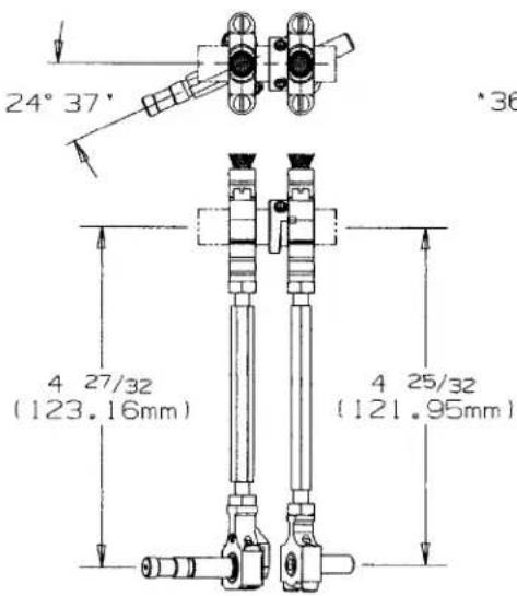
24° 37' *36 4 27/32 (123.16mm) 4 25/32 (121.95mm)FEED DRIVE ASSEMBLY, FEED ROCKER & LOOPER AVOID PARTS
| Ref. | Amt. | ||
| No. | Part No. | Description | Req. |
- 660-207 Oil Seal Ring 1
- 36236A Feed Rocker Shaft 1
- 36237 Differential Feed Adjusting Lever 1
- 36237A Differential Feed Adjusting Link 1
- 22504C Screw 1
- 36236J Differential Driving Link Stud 1
- 36236K Differential Feed Driving Link Slide Block 1
- 36236 Feed Rocker 1
- 77 Screw 2
- 36236B Bushing.... 1
- 22733G Screw 1
- 29478CT Feed Drive Assembly 1
- 29101J Feed Drive Eccentric Assembly 1
- 22587E Screw 2
- 22894W Set Screw 2
- 269 Nut, left thread 1
- 43246 Connecting Rod....1
- 18 Nut, right thread 1
- 35846 Ball Joint 1
- 22729C Screw 2
- 35846B Washer 1
- 35866 Nut 1
- 36236B Bushing 1
- 22733G Screw 1
- 35766B Nut 1
- 35842J Feed Drive and Looper Avoid Drive Lever 1
- 36236A Feed Drive Shaft 1
- 660-207 Oil Seal Ring 1
- 35836C Screw, for feed rocker driving link 1
- 36236H Bushing 1
- 258 Nut 1
- 6042A Washer 1
- 36236C Feed Rocker Driving Link.... 1
- 62238A Link Pin 1
- 35851S Connecting Rod 1
- 35851P Screw 2
text_image
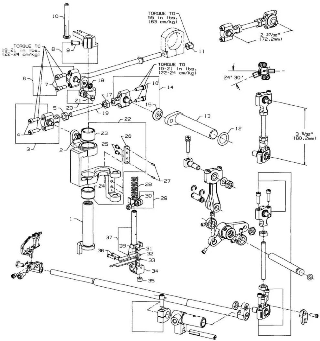
TORQUE TO 19-21 in lbs. (22-24 cm/kg) TORQUE TO 55 in lbs. (63 cm/kg) 2 27/32" (72.2mm) 24° 30' 3 5/32" (80.2mm)KNIFE DRIVING PARTS
| Ref. | Amt. | ||
| No. | Part No. | Description | Req. |
- 36251B Cover Thread Carrier and Hook Driving Sleeve .... 1
- 12934A Nut 1
- 52848B Knife Drive Connection Ball Joint, left .... 1
- 22729C Screw 2
- 18 Nut, right thread 1
- 36251P Cover Thread Carrier and Hook Driving Connection Rod Ball Joint.... 1
- 97A Screw 2
- 36278J Presser Bar Guide 1
- 22569G Screw 1
- 36278H Presser Bar Guide Stud, except UY52, UY60 1
- 52841H Nut 1
- 660-202 Oil Seal Ring 1
- 36261 Knife Drive Lever 1
- 52848C Knife Drive Connection Ball Joint, right 1
- 36G Washer 1
- 22729C Screw 2
- 269 Nut, left thread .... 1
- 12934A Nut 1
- 4761 Knife Drive Connecting Rod .... 1
- 36251C Sleeve Driving Lever, for styles 36200UA52, UAE52, UAK52, UE52, UH52, UX52, UY52 1
- 36251V Sleeve Driving Lever 36200UJ60, UJE60, UM60, UX60, UY60 .... 1
- 22585 Screw 1
- 36273M Knife Driving Bracket 1
- 36273F Bushing 1
- 36273N Bushing 1
- 605A Screw 2
- 36273J Knife Holder Guide Plate 1
- 660-219D Roll Pin 2
- 36273C Knife Holder Spring 1
- 36273K Knife Holder Guide Collar 1
- 22729M Screw 1
- 22799N Screw 1
- 36273D Knife Support 1
- 36270B Knife, upper 1
- 36273G Knife Holder 1
- 22894X Screw 1
- 22767A Screw 2
- 36273A Knife Holder Shank 1
- 1096B Screw 1
text_image
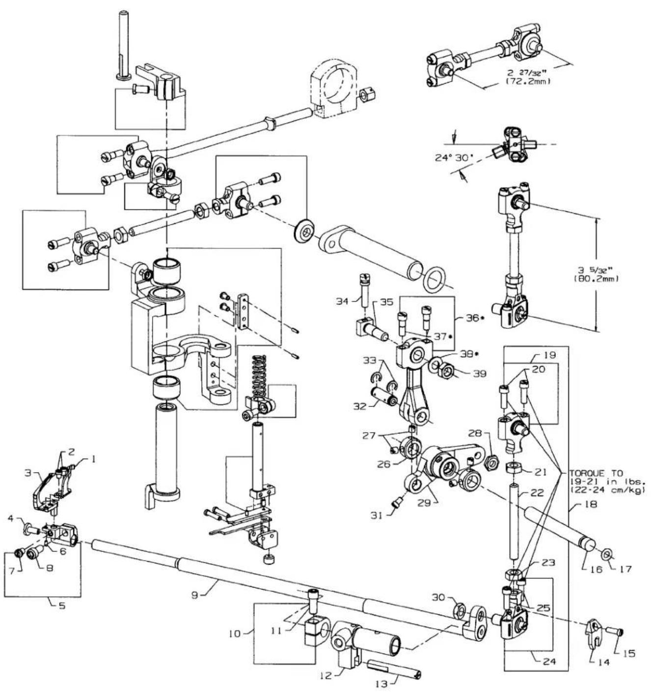
Technical schematic diagram of a mechanical assembly with numbered components and dimensional annotations in millimeters.*Items 36, 37, 38, are part of Looper Drive connection kit 29478FG
| Ref. | Amt. | ||
| No. | Part No. | Description | Req. |
- 36210 Looper Mounted Needle Guard, marked "FZ" 1
- 604 Screw, for needle guard 2
- 36208A Looper 1
- 22585A Screw 1
- 36248 Looper Holder 1
- 1096B Looper Adjusting Screw 1
- 22564D Screw 1
- 22652A-6 Screw 1
- 36249 Looper Rocker Shaft 1
- 35751G Looper Shaft Collar 1
- 22572B Screw 1
- 36249B Looper Shaft Sleeve 1
- 36278C Guide Stud 1
- 41255B Ball Fork 1
- 22747 Screw 1
- 36253B Looper Drive Lever Shaft 1
- 660-221 Oil Seal Ring 1
- 29478CU Looper Drive Connecting Rod Assembly 1
- 35851L Ball Joint, upper 1
- 22729C Screw 2
- 269 Nut, left thread 1
- 4761 Connecting Rod 1
- 18 Nut, right thread 1
- 39145A Ball Joint, lower 1
- 22729C Screw 2
- 12865 Collar 2
- 88 Screw 2
- 15037A Nut 1
- 36253A Looper Drive Lever 1
- 258A Nut 1
- 77 Screw 1
- 52336 Link Pin 1
- 660-215 Retaining Ring 2
- 22795B Screw 1
- 36253G Looper Drive Crank Stud 1
- 36245B Looper Drive Connecting Rod and Ferrule Sub-Assembly 1
- 97A Screw 1
- 53636C Washer 1
- 269 Nut, left thread .... 1
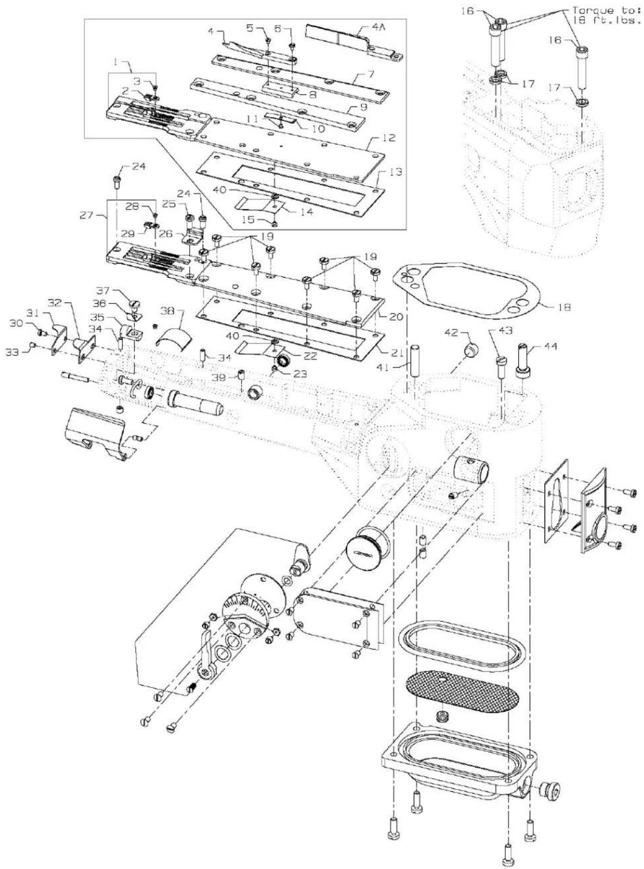
text_image
Exploded view diagram of a mechanical assembly with numbered parts and labeled torque indicatorsRef.
No. Part No.
Description
Amt.
Req.
- 36224H Throat Plate, .050" (1.27mm) step on right side, Styles36200 UH52 .... 1
- 36224K Throat Plate, .050" (1.27mm) step on right side, Styles 36200 UM60 .... 1
- 36240 Stitch Tongue, marked "D", for Throat Plate 36224H 1
- 36240J Stitch Tongue, marked "AC", for Throat Plate 36224K 1
- 22716A Screw, stitch tongue 1
- 23420DB Lap Former, for styles 36200UE52, UE60, UH52, UM60 .... 1
4A. 23420DH Lap Former, for styles 36200UY52, UY60 1 - 22738B Screw, for lap former 1
- 73A Screw, for lap former 1
- 36283J Gib, right, for styles 36200UE52, UE60, UH52, UM60, UY52, UY60 .... 1
- 23423X Lap Former Slide Block, for styles 36200UE52, UE60, UH52, UM60, UY52, UY60 ..... 1
- 36283H Gib, left, for styles 36200UE52, UE60, UH52, UM60, UY52, UY60 .... 1
- 23424Z Spring, for lap former slide block, for styles 36200UE52, UE60, UH52, UM60, UY52, UY60.. 1
- 22716A Screw, for lap former slide block spring, for styles 36200UE52, UE60, UH52, UM60, UY52, UY60
- 36283G Cylinder Cover, for styles 36200UE52, UE60, UH52, UM60, UY52, UY60 .... 1
- 36283F Gasket, for cylinder cover, all styles.... 1
- 36284E Upper Lint Shield, all styles 1
- 22798 Screw, upper lint shield .... 1
- 22653E-24 Screw, for joining cylinder to main frame 3
- 35876U Washer 3
- 36284 Gasket 1
- 98A Screw, for cylinder cover 8
- 36283E Cylinder Cover, for all Styles except 36200UH52, UM60 1
- 36283F Gasket, for cylinder cover 1
- 36284E Upper Lint Shield 1
- 22798 Screw, for upper lint shield 1
- 22562A Screw, for throat plate 3
- 22849 Screw, for edge guide 1
- 36203 Edge Guide, for Styles 36200UA52, UAE52, UAK52, UE52, UE60, UJ60, UJE60 ..... 1
- C36224A Throat Plate, for Styles 36200UA52, UAE52, UAK52, UE52, UX52....1
- C36224J Throat Plate, for Styles 36200UE60, UJ60, UJE60, UX60 .... 1
- C36224P Throat Plate, for Style 36200UY52 1
- C36224Q Throat Plate, for Style 36200UY60 1
22716A Screw, for stitch tongue 1
36240 Stitch Tongue, marked "D", for Throat Plates C36224A, C36224P 1 - 36240J Stitch Tongue, marked "AC", for Throat Plates C36224J, C36224Q ..... 1
- 22KH Screw, for chain cutting knife 1
- 36296B Guard, for chain cutting knife 1
- 36296A Chain Cutting Knife 1
- 22801 Screw, for chain cutting knife 1
- 36251K Dowel Pin 2
- 36283C Cylinder Hinged Spring Support Stud 1
- 36283B Spring 1
- 22585C Screw, spring 1
- 35884K Lower Lint Shield 1
- 531 Screw 1
- 40-107 Washer 1
- 22571A Plug Screw 1
- 667D-16 Dowel Pin 1
- 22596 Screw, for feed bar eccentric stud .... 1
- 36229A-1 Cylinder Alignment Eccentric Pin 1
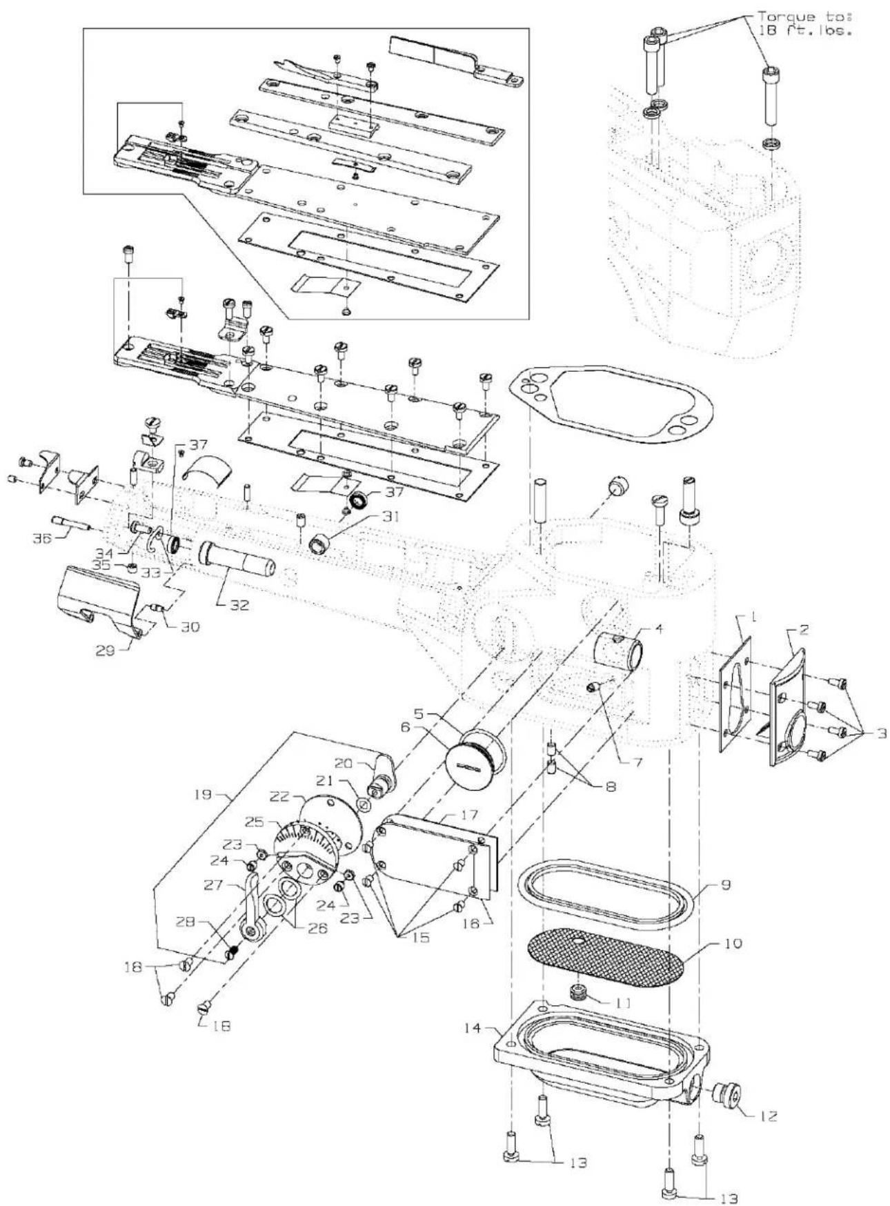
text_image
Technical schematic diagram of a mechanical assembly with numbered components and labeled parts in ChineseCYLINDER BUSHINGS, DIFFERENTIAL FEED CONTROL ASSEMBLY & MISCELLANEOUS CYLINDER COVERS
| Ref. | Amt. | ||
| No. | Part No. | Description | Req. |
- 35884R Gasket, for front cylinder cover and oil gauge .... 1
- 36284C Cylinder Cover and Oil Gauge, front 1
- J87J Screw, for front cylinder cover and oil gauge 4
- 36249A Bushing, for looper shaft, front 1
- 660-1115 "O" Ring 1
- 22539AL Plug Screw 1
- 22560A Screw, for guide stud.... 1
- 531 Screw 2
- 36284F Gasket, for bottom cover 1
- 36293G Screen, for bottom cover 1
- 661-150 Rubber "O" Ring, for screen 1
- 999-196 Oil Drain Plug Screw 1
- 22596 Screw, for bottom cover 4
- 36282 Bottom Cover 1
- 22766 Screw, for cylinder side cover 4
- 36286 Cylinder Side Cover 1
- 36286B Gasket, for cylinder side cover 1
- 87A Screw, for differential feed control assembly 3
- 29478CZ Differential Feed Control Assembly, complete 1
- 36237E Adjusting Lever 1
- 660-220 Oil Seal Ring 1
- 36238F Gasket 1
- 60078Z Nut 2
- 36237H Stop Screw 2
- 36238 Adjusting Plate 1
- 36237J Spring Washer 2
- 36237K Operating Lever 1
- 538 Screw 1
- 36283K Cylinder Hinged Cover 1
- 35883G Pin 1
- 36237L Bushing, for feed bar eccentric stud 1
- 35850F Bushing, for looper shaft, rear 1
- 36256B Looper Thread Guide Wire 1
- 22849 Screw, for looper thread guide wire 1
- 22894W Screw, for cylinder hinged spring support stud .... 1
- 22791E Screw Pin 1
- 660-1117 Oil Seal 2
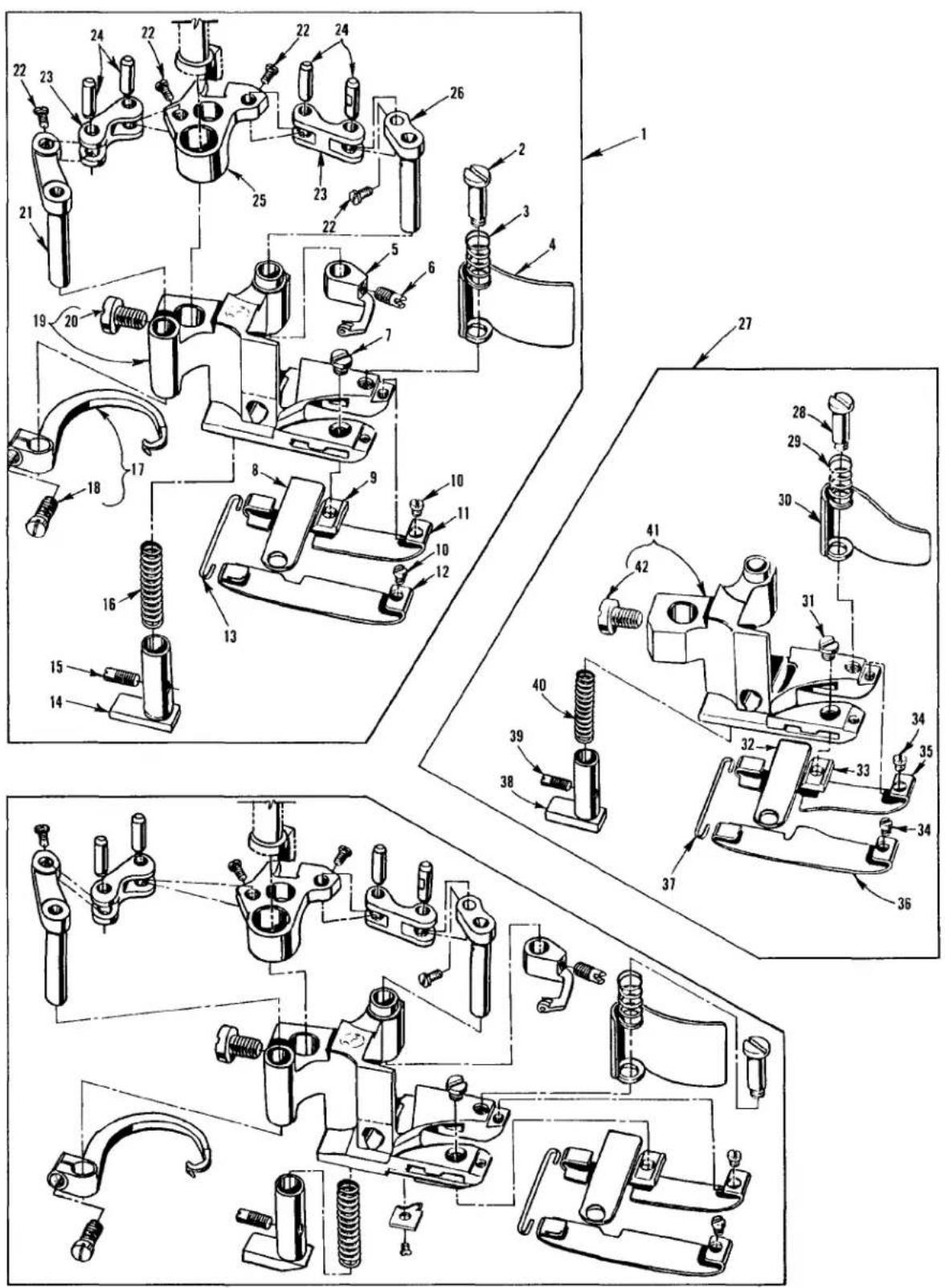
text_image
Technical diagram of mechanical assembly with numbered parts, likely a valve or clamp mechanism, showing exploded and assembled views.PRESSERFEET
| Ref. No. | Part No. | Description | Amt. Req. |
| 1. | 36220A | Presser Foot, complete, for Styles 36200UA52, UAE52 | 1 |
| - | 36220K | Presser Foot, complete, for Styles 36200UJ60, UJE60 | 1 |
| - | 36220L | Presser Foot, complete, for Style 36200UAK52 | 1 |
| 2. | 22731 | Screw, for chip guard | 1 |
| 3. | 36279D | Spring, for chip guard | 1 |
| 4. | 36279C | Chip Guard | 1 |
| 5. | 36251E | Cover Thread Carrier, for 36220 A, L presser foot | 1 |
| - | 36251W | Cover Thread Carrier, for 36220 K presser foot | 1 |
| 6. | 22565A | Screw, cover thread carrier | 1 |
| 7. | 150 | Screw, for stationary knife clamp | 1 |
| 8. | 36250 | Stationary Knife | 1 |
| *9. | 36250B | Stationary Knife Clamp, .213" (5.41mm) ID Mark "A" | 1 |
| *- | 36250G | Stationary Knife Clamp, .222" (5.64mm) ID Mark "B" | 1 |
| *- | 36250J | Stationary Knife Clamp, .226" (5.74mm) ID Mark "J" | 1 |
| 10. | 22738G | Screw, for presser foot shoe | 2 |
| #11. | 36232AY | Presser Foot Shoe, right, for 36220 A, K, L presser foot | 1 |
| #12. | 36231AY | Presser Foot Shoe, left, for 36220 A, K, L presser foot | 1 |
| 13. | 36230D | Shoe Holding Wire | 1 |
| 14. | 36230J | Yielding Section, for 36220 A, K presser foot | 1 |
| - | 36230P | Yielding Section, for 36220 L presser foot | 1 |
| 15. | 22565A | Screw, for yielding section | 1 |
| 16. | 36230C | Spring, for yielding section | 1 |
| 17. | 36251F | Cover Thread Hook, for 36220 A, L presser foot | 1 |
| - | 36251FA | Cover Thread Hook, for 36220 K presser foot | 1 |
| 18. | 22562A | Screw, for cross thread hook | 1 |
| 19. | 36230U | Presser Foot Base, for 36220 A, K, L presser foot | 1 |
| 20. | 94 | Screw, for presser foot base | 1 |
| 21. | 36251H | Cover Thread Hook Driving Lever and Shaft | 1 |
| 22. | 22738P | Screw | 4 |
| 23. | 36251J | Link, for ref. no. 21, 25 and 26 | 2 |
| 24. | 36251K | Link Pin | 4 |
| 25. | 36251L | Cover Thread Carrier and Hook Driving Segment | 1 |
| 26. | 36251G | Cover Thread Carrier Driving Lever and Shaft | 1 |
| 27. | 36220B | Presser Foot, complete, for Styles 36200UX52, UX60 | 1 |
| 28. | 22731 | Screw, for chip guard | 1 |
| 29. | 36279D | Spring, for chip guard | 1 |
| 30. | 36279H | Chip Guard | 1 |
| 31. | 150 | Screw, for stationary knife clamp | 1 |
| 32. | 36250 | Stationary Knife | 1 |
| *33. | 36250B | Stationary Knife Clamp, .213" (5.41mm) ID Mark "A" | 1 |
| *- | 36250G | Stationary Knife Clamp, .222" (5.64mm) ID Mark "B" | 1 |
| *- | 36250J | Stationary Knife Clamp, .226" (5.74mm) IDMark "J" | 1 |
| 34. | 22738G | Screw, for presser foot shoe | 2 |
| #35. | 36232BA | Presser Foot Shoe, right, for 36220 B presser foot | 1 |
| #36. | 36231BA | Presser Foot Shoe, left, for 36220 B presser foot | 1 |
| 37. | 36230D | Shoe Holding Wire | 1 |
| 38. | 36230J | Yielding Section | 1 |
| 39. | 22565A | Screw, for yielding section | 1 |
| 40. | 36230C | Spring, for yielding section | 1 |
| 41. | 36230G | Presser Foot Base, for 36220 B presser foot | 1 |
| 42. | 94 | Screw, for presser foot base | 1 |
* When replacing the stationary knife clamp, order the clamp that has the same I. D. mark as the one being replaced.
See page 50-51 for other presser foot shoes available.
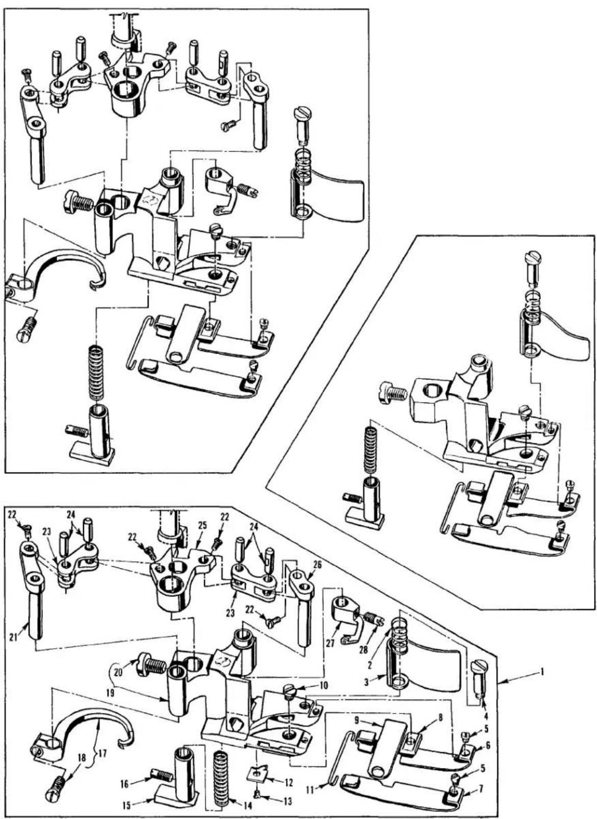
text_image
Technical diagram of mechanical assembly with numbered parts, likely a valve or clamp mechanismPRESSERFEET
| Ref. | Amt. | ||
| No. | Part No. | Description | Req. |
| 1. | 36220E | Presser Foot, complete, for Style 36200UAE52, UE52 | 1 |
| - | 36220H | Presser Foot, complete, for Style 36200UH52 | 1 |
| - | 36220M | Presser Foot, complete, for Style 36200UM60 | 1 |
| - | 36220W | Presser Foot, complete, for Style 36200UE60, UJE60 | 1 |
| 2. | 36279D | Spring, for chip guard | 1 |
| 3. | 36279C | Chip Guard | 1 |
| 4. | 22731 | Screw, for chip guard | 1 |
| 5. | 22738G | Screw, for presser foot shoe | 2 |
| 6. | 36232AM | Presser Foot Shoe, right, for Style 36220 H presser foot | 1 |
| #- | 36232AP | Presser Foot Shoe, right, for Style 36220 M presser foot | 1 |
| #- | 36232AW | Presser Foot Shoe, right, for Style 36220 E, 36220 W presser foot | 1 |
| 7. | 36231AM | Presser Foot Shoe, left, for Style 36220 H presser foot | 1 |
| #- | 36231AP | Presser Foot Shoe, left, for Style 36220 M presser foot | 1 |
| #- | 36231AW | Presser Foot Shoe, left, for Style 36220E, 36220 W presser foot | 1 |
| 8. | 36250B | Stationary Knife Clamp, .213" (5.41mm) ID Mark "A" | 1 |
| * - | 36250G | Stationary Knife Clamp, .222" (5.64mm) ID Mark "B" | 1 |
| * - | 36250J | Stationary Knife Clamp, .226" (5.74mm) ID Mark "J" | 1 |
| 9. | 36250 | Stationary Knife | 1 |
| 0. | 150 | Screw, for stationary knife clamp | 1 |
| 1. | 36230D | Shoe Holding Wire | 1 |
| 2. | 36230R | Cloth Guide Plate | 1 |
| 3. | 22716A | Screw, for cloth guide plate | 1 |
| 4. | 36230C | Spring, for yielding section | 1 |
| 5. | 36230P | Yielding Section | 1 |
| 6. | 22565A | Screw, for yielding section | 1 |
| 7. | 36251F | Cover Thread Hook, for 36220H and 36220E presser foot | 1 |
| - | 36251FA | Cover Thread Hook, for 36220M, 36220 W presser foot | 1 |
| 8. | 22562A | Screw, for cross thread hook | 1 |
| 9. | 36230S | Presser Foot Base, for 36220 H presser foot | 1 |
| - | 36230V | Presser Foot Base, for 36220 M presser foot | 1 |
| - | 36230M | Presser Foot Base, for 36220 E, 36220 W presser foot | 1 |
| 10. | 94 | Screw, for presser foot base | 1 |
| 11. | 36251H | Cover Thread Hook Driving Lever and Shaft | 1 |
| 12. | 22738P | Screw | 4 |
| 13. | 36251J | Link, for ref. no. 21, 25 and 26 | 2 |
| 14. | 36251K | Link Pin | 4 |
| 15. | 36251L | Cover Thread Carrier and Hook Driving Segment | 1 |
| 16. | 36251G | Cover Thread Carrier Driving Lever and Shaft | 1 |
| 17. | 36251E | Cover Thread Carrier, for 36220H and 36220E presser foot | 1 |
| - | 36251W | Cover Thread Carrier, for 36220M, 36220 W presser foot | 1 |
| 18. | 22565A | Screw, for cover thread carrier | 1 |
* When replacing the stationary knife clamp, order the clamp that has the same I. D. mark as the one being replaced.
See page 50-51 for other presser foot shoes available.
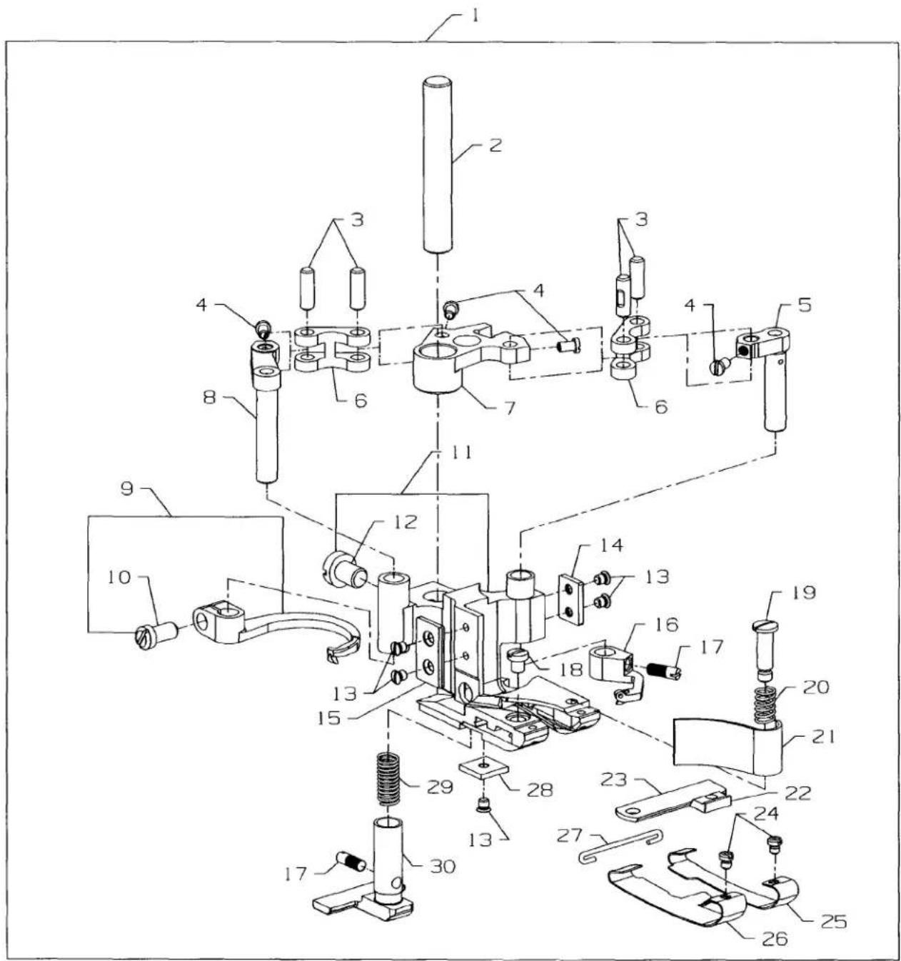
text_image
Technical diagram of a mechanical assembly with numbered components for identificationPRESSER FOOT
| Ref. | Amt. | ||
| No. | Part No. | Description | Req. |
| 1. | 36220X | Presser Foot, complete, for Style 36200UY52 | 1 |
| - | 36220Y | Presser Foot, complete, for Style 36200UY60 | 1 |
| 2. | 22-331 | Pin | 1 |
| 3. | 36251K | Link Pin, for 5, 6 and 8 | 4 |
| 4. | 22738P | Screw | 4 |
| 5. | 36251G | Cross Thread Lever | 1 |
| 6. | 36251J | Driving Lever Link | 2 |
| 7. | 36251L | Driving Segment | 1 |
| 8. | 36251H | Cross Thread Hook Lever | 1 |
| 9. | 36251F | Cross Thread Hook, For 36200UY52 | 1 |
| - | 36251FA | Cross Thread Hook, For 36200UY60 | 1 |
| 0. | 22562A | Screw | 1 |
| 1. | 36230AN | Presser Foot | 1 |
| 2. | 94 | Screw | 1 |
| 3. | 22716A | Screw | 5 |
| 4. | 36230AP | Plate, Right | 1 |
| 5. | 36230AH | Plate, Left | 1 |
| 6. | 36251E | Cover Thread Carrier, For 36200UY52 | 1 |
| - | 36251W | Cover Thread Carrier, For 36200UY60 | 1 |
| 7. | 22565A | Screw | 2 |
| 8. | 150 | Screw | 1 |
| 9. | 22731 | Screw | 1 |
| 10. | 36279D | Spring, Chip Guard | 1 |
| 11. | 36279C | Chip Guard | 1 |
| 12. | 36250K | Stationary Knife Clamp, .213"(5.14mm) ID Mark"D" | 1 |
| - | 36250M | Stationary Knife Clamp, .222"(5.64mm) ID Mark"F" | 1 |
| - | 36250L | Stationary Knife Clamp, .226"(5.74mm) ID Mark"E" | 1 |
| 13. | 36250 | Stationary Knife | 1 |
| 14. | 22738G | Screw | 1 |
| 15. | 36232BD | Presser Foot Shoe, Right | 1 |
| 16. | 36231BD | Presser Foot Shoe, Left | 1 |
| 17. | 36230D | Shoe Holding Wire | 1 |
| 18. | 36230AQ | Cloth Guide Block | 1 |
| 19. | 36230AJ | Spring, Yielding Section | 1 |
| 20. | 36230AL | Yielding Section | 1 |
See page 50-51 for other presser foot shoes available.
PRESSER FOOT SHOE CHART
| STANDARD PRESSER FEET | |
| 1 | 02263 |
| 2 | 0A |
| 3 | B02263 |
| 4 | 0E |
| 5 | H02263 |
| 6 | 0J |
| 7 | K02263 |
| 8 | 0L |
| 9 | 00263 |
| 01 | 0W |
| 11 | X02263 |
| 21 | 0Y |
SELECTING THE PROPER PRESSER FOOT SHOES
THICKNESS OF SHOES
.014 THICK
Used when sewing lightweight material, when light presser foot pressure is essential. Used when sewing medium to heavyweight material, requiring more foot pressure.
.020 THICK
WIDTH OF SHOES
NARROWSHOES Used for medium to heavier material. WIDESHOES Used for light weight material.
LENGTH OF SHOE TOE
SHORTTOE
Adapts easily to a variety of operations and material.
EXTENDED TOE
Gives more feeding surface to the front of the presser foot, and may allow the operator to start the seam without raising the presser foot.
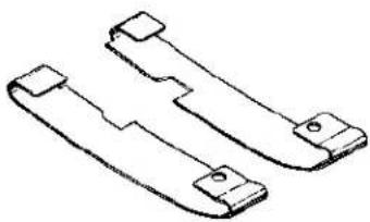
natural_image
Technical line drawing of two mechanical bracket components (no text or symbols)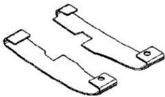
natural_image
Technical line drawing of two mechanical bracket components (no text or symbols)LONG SHOE SHORTSHOE
2
2
2
2
2
2
text_image
Technical diagram of a mechanical assembly with labeled components and parts, including rods, gears, and a central fan.THREAD STAND
| Ref. | Amt. | ||
| No. | Part No. | Description | Req. |
- 21101-S-7 Thread Stand, complete 1
- 21233AJ Bracket Connection, marked "AJ", for Style 36200UAK52.... 1
- 21233KS Bracket Connection, marked "KS", for all other Styles .... 1
- 22651CD-5 Screw, for bracket connection (21233AJ) 4
- 22651CD-5 Screw, for bracket connection (21233KS) 2
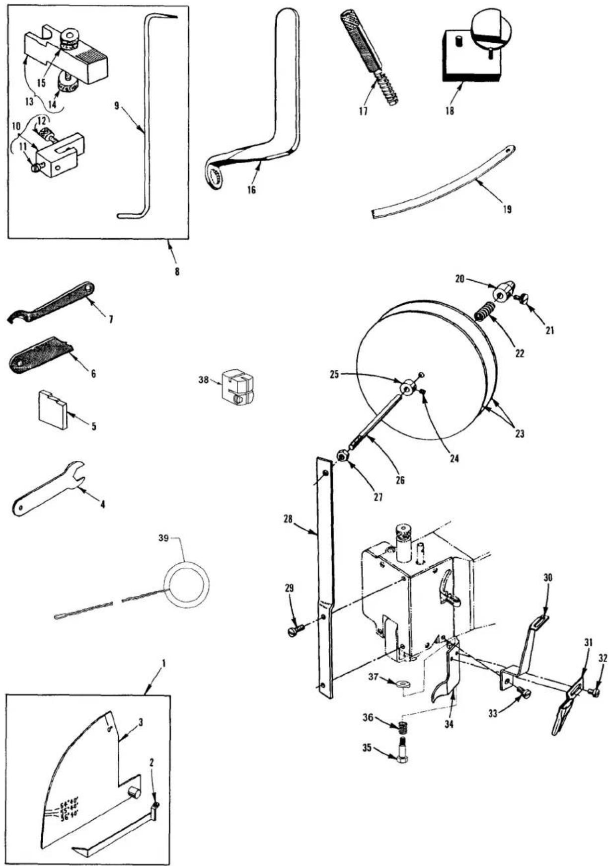
MISCELLANEOUS GAUGES & TAPE REEL PARTS
| Ref. | Amt. | ||
| No. | Part No. | Description | Req. |
| 1. | 21227CN | Looper Travel Gauge, complete | 1 |
| 2. | 21227CM | Looper Travel Gauge Pointer | 1 |
| 3. | 21227CS | Looper Travel Gauge Plate | 1 |
| 4. | 21388AZ | Wrench, for driving link stud | 1 |
| 5. | 21227BU | Needle Height Gauge, for all Styles except 36200UJ60, UM60, UY60 | 1 |
| - | 21227DS | Needle Height Gauge, for Styles 36200UJ60, UM60, UY60 | 1 |
| 6. | 21225F-3/16 | Looper Gauge | 1 |
| 7. | 21388Y | Spanner Wrench | 1 |
| 8. | 21227CG | Synchronizing Gauge, for looper and needle timing, complete | 1 |
| 9. | 21227CK | Synchronizing Gauge Rod | 1 |
| 0. | 21227CJ | Looper Clamp and Height Gauge | 1 |
| 1. | 22738 | Screw | 1 |
| 2. | 22703A | Screw | 1 |
| 3. | 21227CH | Needle Setting Block | 1 |
| 4. | 14087 | Thumbscrew | 1 |
| 5. | 1347A | Nut | 1 |
| 6. | TT85 | Wrench, for 3/16" square nut on screw | 1 |
| 7. | 21227BV | Looper Avoid Gauge | 1 |
| 8. | 21227CV | Cover Thread Hook Gauge | 1 |
| 9. | 23279D | Folder Threader | 1 |
| 10. | 753 | Adjustable Axle Cone | 1 |
| 11. | 188D | Screw, for adjustable axle cone | 1 |
| 12. | 51292F-8 | Spring, for tape holder disc | 1 |
| 13. | 21178 | Tape Holder Disc | 2 |
| 14. | 88 | Screw, for collar | 1 |
| 15. | 161 | Collar | 1 |
| 16. | 21114W | Tape Reel Axle | 1 |
| 17. | 258A | Nut, for tape reel axle | 1 |
| 18. | 21171Z | Tape Reel Frame | 1 |
| 19. | 22729A | Screw, for tape reel frame | 2 |
| 20. | 21171AA | Tape Guide | 1 |
| 21. | 23401P-7/16 | Tape Folder | 1 |
| 22. | 357 | Screw, for tape folder | 2 |
| 23. | 28 | Screw, for tape guide | 1 |
| 24. | 36279E | Frame Chip Guard | 1 |
| 25. | 22777B | Screw, for Frame Chip Guard | 1 |
| 26. | 36279B | Spring, for Frame Chip Guard | 1 |
| 27. | 36279A | Washer, for Frame Chip Guard | 1 |
| 28. | 21227AR | Torque Rod, for Needle Head | 1 |
| 29. | 39899A | Threading Wire | 1 |
*Indicates tape holder parts for Styles 36200UX52, UX60
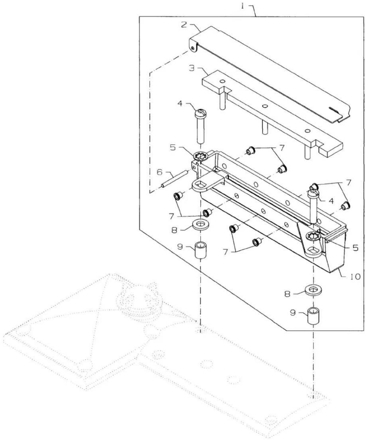
text_image
Technical diagram of a mechanical assembly with numbered components and a wireframe view of the component.THREAD LUBRICATOR
| Ref. | Amt. | ||
| No. | Part No. | Description | Req. |
- 29480AZY Needle Thread Lubricator Complete 1
- 35893J Reservoir Cover 1
- 666-339 Reservoir Wick 1
- 22826 Screw 2
- 660-342 Washer 2
- 660-219AX Pin.... 1
- 50358M Eyelet 8
- 8372A Washer 2
- 35874W Spacer 2
- 35893K Reservoir 1
- 28604W Bottle of Silicone (not shown) 1
NUMERICAL INDEX OF PARTS
| Part No. | Page No. | Part No. | Page No. | Part No. | Page No. | Part No. | Page No. | Part No. | Page No. |
| 109 | 31 | 22565A | 51, 53 | 22799N | 41 | 35792 | 31 | 36205J | 37 |
| 1096 | 27 | 22569B | 23 | 22801 | 27, 45 | 35792T | 31 | 36205N | 37 |
| 1096B | 41, 43 | 22569D | 25 | 22826 | 61 | 35815C | 29 | 36208A | 43 |
| 11550209 | 27 | 22569G | 41 | 22829 | 25 | 35817E | 33 | 36210 | 43 |
| 12538 | 35 | 22571A | 45 | 22839 | 23 | 35836C | 39 | 36218 | 35 |
| 12865 | 43 | 22571B | 27 | 22839D | 31 | 35842J | 39 | 36218J | 35 |
| 12934A | 23, 41 | 22572B | 43 | 22845M | 37 | 35846 | 39 | 36220A | 49 |
| 1347A | 59 | 22574 | 29 | 22849 | 45, 47 | 35846B | 39 | 36220B | 49 |
| 14087 | 59 | 22578H | 37 | 22881A | 33 | 35847X | 29 | 36220E | 51 |
| 150 | 49, 51, 53 | 22580 | 27 | 22894AM | 27 | 35850F | 47 | 36220H | 51 |
| 15037A | 43 | 22585 | 41 | 22894AM | 29 | 35851L | 43 | 36220K | 49 |
| 161 | 59 | 22585A | 27 | 22894BK | 31 | 35851P | 39 | 36220L | 49 |
| 18 | 37, 39 | 22585A | 31, 43 | 22894E | 29 | 35851S | 39 | 36220M | 51 |
| 18 | 41, 43 | 22585B | 35 | 22894J | 27, 31 | 35859D | 33 | 36220W | 51 |
| 188D | 59 | 22585C | 31, 35 | 22894K | 27 | 35859J | 33 | 36220X | 53 |
| 21101-S-7 | 57 | 22585C | 45 | 22894W | 27 | 35860D | 25 | 36220Y | 53 |
| 21114W | 59 | 22587B | 29 | 22894W | 29, 37 | 35862A | 29 | 36221D | 29 |
| 21171AA | 59 | 22587E | 27, 37 | 22894W | 39, 47 | 35866 | 39 | 36221K | 29 |
| 21171Z | 59 | 22587E | 39 | 22894X | 41 | 35866A | 25 | 36222A | 29 |
| 21178 | 59 | 22587H | 37 | 22KH | 23, 45 | 35866B | 25 | 36222C | 27 |
| 21225F-3/16 | 59 | 22596 | 45, 47 | 23279D | 59 | 35874W | 61 | 36223 | 27 |
| 21227AR | 59 | 22596B | 29 | 23401P-7/16 | 59 | 35876U | 45 | 36223A | 27 |
| 21227BU | 59 | 22651CD-5 | 57 | 23420DB | 45 | 35880M | 31 | 36224H | 45 |
| 21227BV | 59 | 22652A-6 | 43 | 23420DH | 45 | 35883AL | 25 | 36224K | 45 |
| 21227CG | 59 | 22653B-8 | 35 | 23423X | 45 | 35883G | 47 | 36225 | 37 |
| 21227CH | 59 | 22653E-24 | 45 | 23424Z | 45 | 35884K | 45 | 36225A | 37 |
| 21227CJ | 59 | 22703A | 59 | 255 | 31 | 35884R | 47 | 36226A | 37 |
| 21227CK | 59 | 22711 | 23 | 258 | 39 | 35887AE | 23 | 36226B | 37 |
| 21227CM | 59 | 22716A | 45, 51 | 258A | 31, 43 | 35887AF | 25 | 36226H | 37 |
| 21227CN | 59 | 22716A | 53 | 258A | 59 | 35887AG | 23 | 36226J | 37 |
| 21227CS | 59 | 22729A | 59 | 269 | 37, 39 | 35887M | 23 | 36226K | 37 |
| 21227CV | 59 | 22729C | 37, 39 | 269 | 41, 43 | 35887R | 23 | 36229A-1 | 45 |
| 21227DS | 59 | 22729C | 41, 43 | 28 | 33, 59 | 35887X | 23 | 36229B | 33 |
| 21233AJ | 57 | 22729M | 41 | 28604W | 61 | 35887Z | 25 | 36229F | 33 |
| 21233KS | 57 | 22731 | 49, 51, 53 | 28A | 33 | 35888N | 23 | 36230AH | 53 |
| 21388AZ | 59 | 22733B | 25 | 28C | 25, 35 | 35888T | 23 | 36230AJ | 53 |
| 21388Y | 59 | 22733G | 39 | 29101J | 27, 39 | 35889H | 23 | 36230AL | 53 |
| 21756G | 27 | 22738 | 59 | 29103T | 27, 37 | 35890E | 25 | 36230AN | 53 |
| 22-331 | 53 | 22738B | 45 | 29105BH | 25 | 35890P | 23 | 36230AP | 53 |
| 22504C | 39 | 22738C | 33 | 29472AC | 27 | 35893G | 23 | 36230AQ | 53 |
| 22513 | 33 | 22738G | 49, 51 | 29472Y | 27 | 35893H | 23 | 36230C | 49, 51 |
| 22516A | 23 | 22738G | 53 | 29476XC | 23 | 35893J | 61 | 36230D | 49 |
| 22517 | 31 | 22738H | 35 | 29476YN | 35 | 35893K | 61 | 36230D | 51, 53 |
| 22519 | 31 | 22738P | 49, 51 | 29476YP | 35 | 35894J | 27 | 36230G | 49 |
| 22519F | 27 | 22738P | 53 | 29478CS | 37 | 35894L | 27 | 36230J | 49 |
| 22524 | 33, 35 | 22747 | 37, 43 | 29478CT | 39 | 35895X | 27 | 36230M | 51 |
| 22528 | 37 | 22758E | 35 | 29478CU | 43 | 35895Y | 27, 29 | 36230P | 49, 51 |
| 22539AA | 23 | 22759A | 23 | 29478CZ | 47 | 35896D | 35 | 36230R | 51 |
| 22539AL | 47 | 22766 | 29, 47 | 29480AZY | 61 | 35897BU | 27 | 36230S | 51 |
| 22539M | 23 | 22767A | 41 | 318 | 35 | 35897BV | 27 | 36230U | 49 |
| 22539T | 25 | 22768B | 25 | 33174B | 37 | 35897BW | 27 | 36230V | 51 |
| 22560A | 35, 47 | 22777B | 33, 59 | 357 | 59 | 35897BY | 29 | 36231AM | 51 |
| 22562A | 29, 45 | 22784F | 31 | 35751G | 43 | 35897CK | 35 | 36231AP | 51 |
| 22562A | 49, 51 | 22791D | 25 | 35761D | 25 | 36203 | 45 | 36231AW | 51 |
| 22562A | 53 | 22791E | 47 | 35763F | 29 | 36204 | 23 | 36231AY | 49 |
| 22564 | 29 | 22795B | 43 | 35763G | 29 | 36204A | 23 | 36231BA | 49 |
| 22564B | 23, 25 | 22797 | 29 | 35766B | 39 | 36205A | 37 | 36231BD | 53 |
| 22564D | 43 | 22798 | 45 | 35767 | 33 | 36205B | 37 | 36232AM | 51 |
| 22565A | 27, 49 | 22799B | 25 | 35781D | 25 | 36205H | 37 | 36232AP | 51 |
NUMERICAL INDEX OF PARTS
| Part No. | Page No. | Part No. | Page No. | Part No. | Page No. | Part No. | Page No. | Part No. | Page No. |
| 36232AW | 51 | 36251J | 49 | 36279C | 51, 53 | 36294C | 33 | 660-220 | 37, 47 |
| 36232AY | 49 | 36251J | 51, 53 | 36279D | 49 | 36296A | 45 | 660-221 | 43 |
| 36232BA | 49 | 36251K | 45, 49 | 36279D | 51, 53 | 36296B | 45 | 660-254C | 31 |
| 36232BD | 53 | 36251K | 51, 53 | 36279E | 59 | 36296C | 35 | 660-261 | 33 |
| 36234C | 37 | 36251L | 49 | 36279H | 49 | 36297J | 27 | 660-342 | 61 |
| 36234E | 37 | 36251L | 51, 53 | 36279L | 33 | 36297M | 27 | 660-935 | 23 |
| 36234F | 37 | 36251M | 29 | 36279M | 33 | 36298G | 31 | 661-150 | 47 |
| 36234G | 37 | 36251N | 29 | 36279N | 33 | 36298H | 31 | 664F-16 | 35 |
| 36234M | 37 | 36251P | 41 | 36280A | 31 | 36G | 41 | 666-338 | 27 |
| 36236 | 39 | 36251V | 41 | 36280C | 31 | 39145A | 43 | 666-339 | 61 |
| 36236A | 39 | 36251W | 49 | 36280D | 31 | 39592AK | 31 | 666-340A | 35 |
| 36236B | 39 | 36251W | 51, 53 | 36280J | 33 | 39593C | 23 | 666-341 | 45 |
| 36236C | 39 | 36253A | 43 | 36280N | 31 | 39899A | 59 | 667D-16 | 45 |
| 36236E | 37 | 36253B | 43 | 36280S | 31 | 40-107 | 45 | 671B3 | 27 |
| 36236F | 37 | 36253G | 43 | 36280T | 31 | 41071G | 23, 27 | 73A | 23, 25, 45 |
| 36236G | 37 | 36256 | 23 | 36280U | 31 | 41255B | 37, 43 | 73C | 23 |
| 36236H | 37, 39 | 36256A | 23 | 36280V | 31 | 43246 | 39 | 753 | 59 |
| 36236J | 39 | 36256B | 47 | 36280W | 31 | 4761 | 41, 43 | 77 | 29, 39, 43 |
| 36236K | 39 | 36260A | 25 | 36282 | 47 | 50358M | 61 | 8372A | 33, 61 |
| 36237 | 39 | 36261 | 41 | 36283B | 45 | 50393-140 | 27 | 86 | 31 |
| 36237A | 39 | 36261A | 27 | 36283C | 45 | 51054A | 29 | 87A | 47 |
| 36237E | 47 | 36263 | 29 | 36283E | 45 | 51254K | 29 | 87U | 37 |
| 36237H | 47 | 36264B | 33 | 36283F | 45 | 51259 | 33 | 88 | 43, 59 |
| 36237J | 47 | 36264D | 29 | 36283G | 45 | 51292F-2 | 31 | 90 | 23, 27 |
| 36237K | 47 | 36264E | 33 | 36283H | 45 | 51292F-4 | 31 | 93 | 23 |
| 36237L | 47 | 36264F | 33 | 36283J | 45 | 51292F-5 | 31 | 93A | 23 |
| 36237M | 35 | 36266 | 31 | 36283K | 47 | 51292F-8 | 59 | 94 | 31, 49 |
| 36238 | 47 | 36266A | 31 | 36283M | 35 | 52336 | 43 | 94 | 51, 53 |
| 36238F | 47 | 36270B | 41 | 36283P | 35 | 52841H | 41 | 97A | 41, 43 |
| 36240 | 45 | 36271 | 25 | 36283R | 31 | 52848B | 41 | 98A | 45 |
| 36240J | 45 | 36271A | 25 | 36283S | 31 | 52848C | 41 | 9937 | 35 |
| 36244 | 37 | 36271E | 25 | 36283T | 31 | 52958C | 23 | 999-196 | 47 |
| 36244A | 37 | 36271G | 25 | 36283U | 31 | 52958F | 23 | B3319704L00 | 31 |
| 36245B | 43 | 36271H | 25 | 36284 | 45 | 531 | 45, 47 | B3530555000 | 23 |
| 36248 | 43 | 36273A | 41 | 36284C | 47 | 53636C | 43 | C36224A | 45 |
| 36249 | 43 | 36273C | 41 | 36284E | 45 | 538 | 47 | C36224J | 45 |
| 36249A | 47 | 36273D | 41 | 36284F | 47 | 56354D | 29 | C36224P | 45 |
| 36249B | 43 | 36273F | 41 | 36286 | 47 | 56390E | 23 | C36224Q | 45 |
| 36250 | 49, 51 | 36273G | 41 | 36286B | 47 | 60078Z | 47 | C50092S | 31 |
| 36250 | 53 | 36273J | 41 | 36289 | 33 | 604 | 43 | CL21 | 23, 25 |
| 36250B | 49, 51 | 36273K | 41 | 36289A | 35 | 6042A | 23 | CO67E | 23 |
| 36250G | 49, 51 | 36273M | 41 | 36289B | 33 | 6042A | 35, 39 | CQ00000000 | 35 |
| 36250J | 49, 51 | 36273N | 41 | 36289H | 33 | 605A | 41 | CQ00000000 | 37 |
| 36250K | 53 | 36278 | 33 | 36289J | 35 | 61321J | 29 | J87J | 47 |
| 36250L | 53 | 36278A | 33 | 36290A | 25 | 61321L | 29 | LA528 | 23 |
| 36250M | 53 | 36278C | 43 | 36290B | 25 | 62238A | 37, 39 | PS0200062KH | 35 |
| 36251B | 41 | 36278F | 35 | 36290D | 23 | 62271B | 25 | SS7090910TP | 31 |
| 36251C | 41 | 36278H | 35, 41 | 36290E | 35 | 660-1115 | 47 | SS7110510SP | 25 |
| 36251D | 33 | 36278J | 41 | 36292K | 31 | 660-1117 | 47 | SS7110840SP | 31 |
| 36251E | 49 | 36278K | 33 | 36292M | 31 | 660-1130 | 35 | TT85 | 59 |
| 36251E | 51, 53 | 36278L | 35 | 36292N | 31 | 660-1131 | 35 | W56392F | 31 |
| 36251F | 49 | 36278M | 35 | 36292Q | 31 | 660-202 | 29, 41 | WO3 | 35 |
| 36251F | 51, 53 | 36278R | 35 | 36293B | 23 | 660-206 | 25 | WZ0641510KP | 35 |
| 36251FA | 49 | 36278S | 33 | 36293E | 23 | 660-207 | 27, 39 | ||
| 36251FA | 51, 53 | 36278T | 35 | 36293G | 47 | 660-212 | 23 | ||
| 36251G | 49 | 36278U | 35 | 36293K | 27 | 660-215 | 43 | ||
| 36251G | 51, 53 | 36279A | 33, 59 | 36293L | 27 | 660-219AX | 61 | ||
| 36251H | 49 | 36279B | 33, 59 | 36293M | 27 | 660-219D | 41 | ||
| 36251H | 51, 53 | 36279C | 49 | 36294B | 35 | 660-219P | 27 |
Union Special Corporation
Corporate Office
One Union Special Plaza
Huntley, IL 60142
Phone: 847-669-5101
Fax: 847·669·4454
Union Special GmbH
EuropeanDistributionCenter
Raiffeisenstrasse 3
D-71696 Möglingen, Germany
Tel: 49·07141·247·0
Fax: 49·07141·247·100
JUKICORPORATION
INTERNATIONAL SALES DIVISION
8-2-1, KOKURYO - CHO,