
200-1 - Sewing machine Union Special - Free user manual and instructions
Find the device manual for free 200-1 Union Special in PDF.


User questions about 200-1 Union Special
0 question about this device. Answer the ones you know or ask your own.
Ask a new question about this device
Download the instructions for your Sewing machine in PDF format for free! Find your manual 200-1 - Union Special and take your electronic device back in hand. On this page are published all the documents necessary for the use of your device. 200-1 by Union Special.
USER MANUAL 200-1 Union Special
BUTTON SEWING MACHINE
Catalog No. 194-4
INSTRUCTIONS
FOR
ADJUSTING AND OPERATING
LIST OF PARTS
Styles
| 200-1 | 200-9 | 200-21 |
| 200-2 | 200-10 | 200-22 |
| 200-6 | 200-15 | 200-23 |
| 200-7 | 200-16 | 200-24 |
| 200-8 | 200-17 | 200-25 |
200-26 200-27
Third Edition
© 1962 and 1977
By
Union Special Corporation
Rights Reserved in All Countries
INDUSTRIAL SEWING MACHINES
CHICAGO
Printed in U.S.A.
April, 1981
IDENTIFICATION OF MACHINES
Each UNION SPECIAL LEWIS machine carries a style number, which in this class of machines, is stamped in the style plate on the left side of the arm.
The serial number of each machine is stamped in the right side of the cylinder toward the back.
APPLICATION OF CATALOG
This catalog applies specifically to the styles of machines as listed herein.
All references to direction, such as right and left, forward and back, etc., are taken from the operator's position while seated at the machine.
The operating direction of the pulley is away from the operator.
DESCRIPTION OF MACHINES
High production, single thread, button sewing machines. Sews all popular sizes and types of flat two hole, four hole, and shank buttons. Attachments available to sew snaps, hooks and eyes, and for tacking operations. Lever adjusted stitch range to sew 8, 16 or 32 stitches on some styles, and 6, 12, or 24 on others. Automatic stitching cycle, cam drive with stop motion clutch. Single treadle operation.
200-1 Right to Left Stitching Flat Buttons. For two or four hole buttons on blouses, coats, shirts, pajamas, and similar garments of light, medium and heavy materials. Sews right to left, 8, 16, or 32 parallel stitches. Equipped to sew buttons 14 to 45 ligne. Can be equipped to sew buttons 30 to 60 ligne when specified.
NOTE: 1 Ligne equals .025 inch. 40 Ligne equals 1 inch.
200-2 Same as Style 200-1, except sews 6, 12, or 24 stitches.
200-6 Diagonal Stitching Flat Buttons. Similar to Style 200-1, except sews 16 or 32 diagonal stitches in four hole buttons. Two hole buttons can be stitched right to left or back to front with 8 or 16 stitches.
200-7 Same as Style 200-6, except sews 6, 12, or 24 stitches.
200-8 Back to Front Stitching Flat Buttons. Same as Style 200-1, except sews 8, 16, or 32 parallel stitches back to front in two or four hole buttons.
200-9 Same as 200-8, except sews 6, 12, or 24 stitches.
200-10 Right to Left Stitching Flat Buttons With No Cross-over Stitch. Sews 16 parallel stitches in four hole buttons only. Equipped with special knife and nipper mechanism to cut cross-over stitch between the two rows of parallel stitches. Recommended for high quality garments, such as men's sack coats, suit coats, ladies' suits and coats.
200-15 Same as Style 200-1, except equipped with knife for cutting thread at end of stitch cycle. Primarily used with heavy thread where thread cutter is needed. Recommended with certain types of automatic button feeders and for use with necking attachment.
200-16 Tacking. Equipped with tacking clamp. Sews 8 or 16 stitches back to front. Recommended for tacking bows on blouses, dresses, etc., cuffs on trousers, side pockets on trousers, size tickets, and similar operations.
200-17 Same as Style 200-16, except sews 6 or 12 stitches.
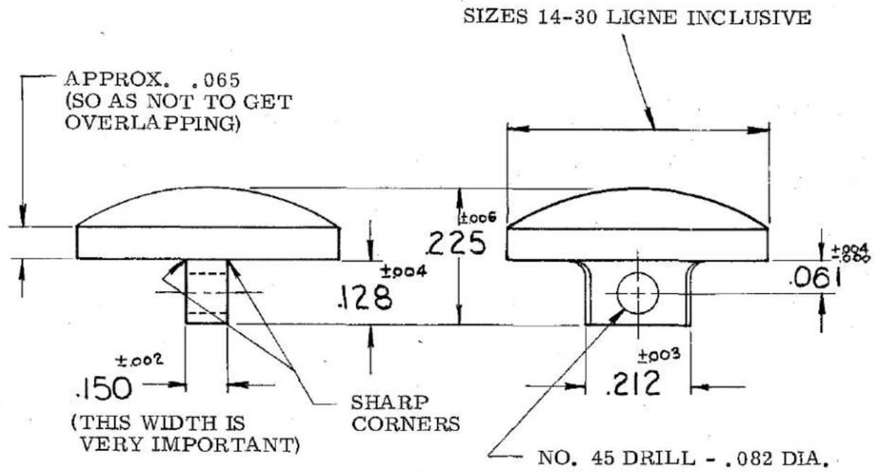
200-21 For Hopper Fed Shank Buttons. Similar to Style 200-6, except prepared for and including Rochester Shank Button Hopper. Stitches back to front and sews 8, 16, or 32 stitches. Button Hopper handles self molded shank buttons from 14 to 30 ligne within other dimensions indicated on sketch on next page.
DESCRIPTION OF MACHINES (continued)
200-22 Same as Style 200-21, except sews 6, 12, or 24 stitches.
text_image
SIZES 14-30 LIGNE INCLUSIVE APPROX. .065 (SO AS NOT TO GET OVERLAPPING) ±006 225 ±004 .128 ±002 .150 (THIS WIDTH IS VERY IMPORTANT) SHARP CORNERS ±003 .212 NO. 45 DRILL - .082 DIA.200-23 For Hopper Fed Flat Buttons. Similar to Style 200-1, except prepared to receive Rochester So-Thru Button Hopper. For use on shirts, pajamas, blouses, or any garments where continued use of similar size buttons is required. Stitches right to left on two or four hole buttons and sews 8, 16, or 32 stitches. No button clamp furnished. Sample button must be submitted with order. See Page 35 for list of available Rochester So-Thru Button Hoppers.
200-24 Same as Style 200-23, except sews 6, 12, or 24 stitches.
200-25 Right to Left Stitching Flat Buttons. For two hole buttons on dresses, blouses, coats, shirts, pajamas and similar garments of light, medium and heavy weight material. Sews right to left, 16 or 32 parallel stitches. Can also be used for 16 stitches on four hole buttons and when used this way, the cross-over stitch will be diagonal and there is no tacking stitch previous to cross-over. Machine cannot be used 1/2 cycle or 8 stitches. Equipped to sew buttons 14 to 45 ligne.
200-26 Same as Style 200-1, except sews right to left, 12 or 24 parallel stitches. Produces 12 stitches on two hole buttons in the half cycle. It also may be used to produce 24 stitches on four hole buttons in the full cycle. Equipped to sew buttons 14 to 45 ligne.
200-27 Right to Left Stitching Shank Buttons. For shank buttons on dresses, blouses, coats, shirts, pajamas and similar garments of light, medium and heavy weight material. Sews right to left, 8, 16, or 32 parallel stitches. Equipped to sew shank buttons 10 to 40 ligne.
OTHER APPLICATIONS
By the selection of the proper attachments, listed and illustrated in the Parts section of this book, many of these machine Styles can be used for operations other than those for which they are described. A list of these variations follows:
200-1 Can be used for shank buttons, snaps, hooks and eyes, tacking, shanking, and necking operations.
200-2 Same variations as for Style 200-1.
OTHER APPLICATIONS (Continued)
200-6 Can be used for shank buttons, hooks and eyes, drapery rings, tacking, shanking, and necking operations.
200-7 Same variations as for Style 200-6.
200-8 Can be used for snaps, drapery rings, tacking, and shanking operations.
200-9 Same variations as for Style 200-8.
200-10 Can be used for shanking operations.
200-15 Can be used for shank buttons, snaps, hooks and eyes, tacking, shanking, and and necking operations.
200-16 Can be used for two hole buttons, stitched back to front only, and drapery rings.
200-17 Same variations as for Style 200-16.
OILING
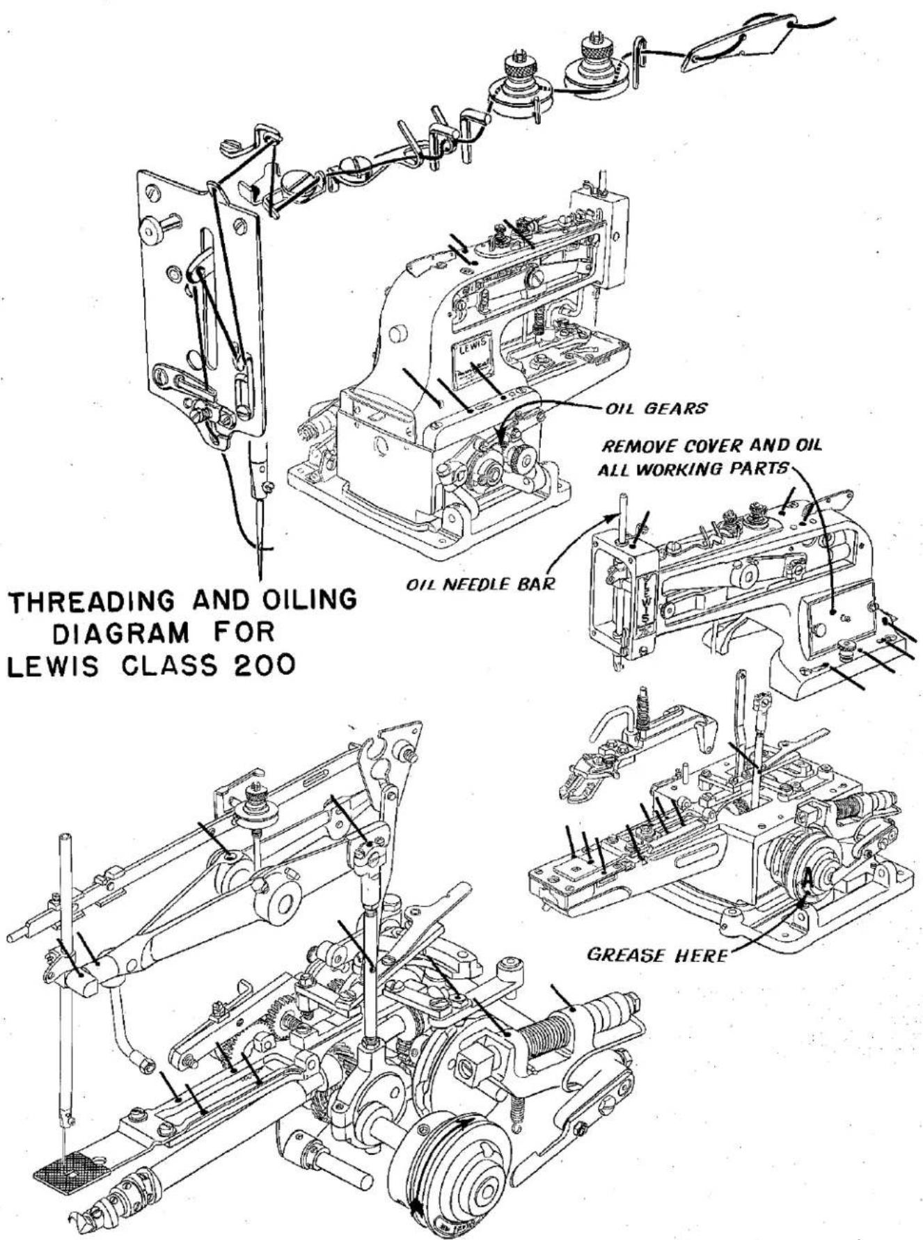
These machines should be oiled twice daily, before the morning and afternoon starts. Use a good grade of straight mineral oil of a Saybolt viscosity of 90 to 125 seconds at 100^ Fahrenheit.
Most of the oiling places on the machines are readily identifiable because of the fact they are painted red. However, reference to the oiling diagram Fig. 13, on Page 14, will be beneficial.
Please note that it will be necessary to remove arm cover and side cover, and to open the hinged base covers and tilt machine on its side to reach some of the oiling places.
Also note that there is a label on the pulley which reads "Grease Here". A tube of grease is furnished with the machine, and periodically, the plug screw in the pulley should be removed, the grease level checked and replenished if required. The greasing place is indicated by the letter "A" in the diagram. All other places shown are oiled.
Tubes of grease may be ordered under part No. 28604 P.
SPEED
The recommended speed of these machines is 1500 R.P.M.
NEEDLES
Needles for these machines are divided into three categories - short, long with short shank, and long with extra short shank.
Generally speaking, the shortest needle required to perform a given operation should be used. In making the selection, consideration should be given to the height of the button, thickness of material, amount of shanking required, and whether or not a stay button is to be used.
NEEDLES (Continued)
For shank buttons, the diameter of the button, the thickness of the shank, and the height of the work support block should be considered.
Available needles for the Class 200 machines are:
| Blade Dia. | Short | Long With Short Shank | Long With Extra Short Shank | Extra Long With Extra Short Shank |
| .036'' | 29S-090/036 | 29LSS-090/036 | - | - |
| .040'' | 29S-100/040 | 29LSS-100/040 | 29LES-100/040 | - |
| .044'' | 29S-110/044 | 29LSS-110/044 | 29LES-110/044 | 29ELS-110/044 |
| .049'' | 29S-125/049 | 29LSS-125/049 | 29LES-125/049 | 29ELS-125/049 |
| .057'' | - | 29LSS-140/054 | - | - |
For use with large diameter shank buttons, and high work support block, the long needle with extra short shank is recommended.
For use with extra large diameter shank buttons and high work support block, the extra long needle with extra short shank is recommended.
In changing from short to long needles, or vice versa, the needle bar height must be set to the proper timing lines as described in the adjusting instructions in this catalog.
Unless instructions to the contrary are received, machines in Class 200 will be sewed off and shipped with the following needle specifications:
| Machine Style | Needle | Machine Style | Needle |
| 200-1 | 29S-100/040 | 200-17 | 29S-110/044 |
| 200-2 | 29S-100/040 | 200-21 | 29LSS-110/044 |
| 200-6 | 29LSS-110/044 | 200-22 | 29LSS-110/044 |
| 200-7 | 29LSS-110/044 | 200-23 | 29S-100/040 |
| 200-8 | 29LSS-110/044 | 200-24 | 29S-100/040 |
| 200-9 | 29LSS-100/040 | 200-25 | 29S-100/040 |
| 200-10 | 29LSS-110/044 | 200-26 | 29S-100/040 |
| 200-15 | 29S-100/040 | 200-27 | 29LES-110/044 |
| 200-16 | 29S-110/044 |
Selection of proper needle size is determined by size of thread, weight of material, and the type of button used.
To have needle orders promptly and accurately filled, an empty container, a sample needle, or the type number should be forwarded. A complete order would read: "100 Needles, Type 29LSS-110/044".
CHANGING NEEDLES
When changing the needle, make sure that it is inserted in the needle bar as far as it will go, with the long groove to the front and the spot or scarf to the rear, and tighten set screw securely.
A cross hole drilled in the needle bar can also be used to determine if the needle has been inserted as far as it will go.
Immediately discard any needle which may have a hooked or blunt point.
THREADING
To thread machine, put in stop position, and thread in accordance with diagram Fig. 13, Page 14.
ADJUSTING
CAUTION! Do not run the machine under power during the following adjusting operations until ready to sew.
text_image
A B 3/8" K G H E D GFig. 1
The Class 200 machines are equipped with a cycling mechanism, which, with one pressure on the operating treadle, produce 6, 12, 24, or 8, 16, 32 stitches and automatically stops.
In the following instructions, reference is made to "the machine in stop position".
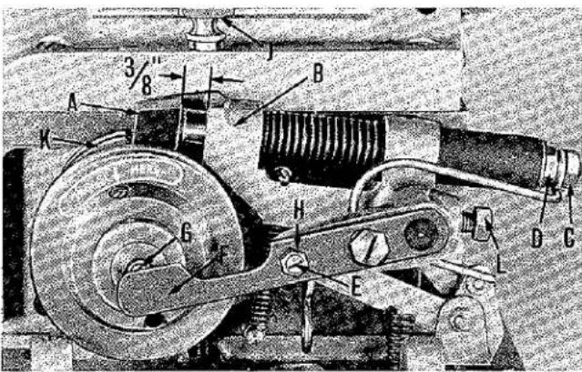
This position is that which is shown in Fig. 1 with the stop motion disc and pawl (K) against the plunger (A).
operated, depress the operating treadle, and turn the pulley and stop motion disc in operating direction.
To release the machine from stop position so that it may be manually
ADJUSTING CLUTCH
With the machine in stop position, the stop motion plunger (A, Fig. 1) should be set so that there is 3/8 inch clearance between the bottom of the plunger and the plunger lever bracket (B). Loosen the back lock nut (C), and adjust the front nut (D) to obtain this setting. Lock the back nut. Adjust screw (E) in cam lever (F) so that there is 1/32 inch clearance between ball (G) and the thin section of lever (F) when the pulley is pressed into towards machine. Lock screw with nut (H). Make sure that set screw (L) is securely tightened.
ADJUSTING STOP MOTION (PRIOR TO SER. NO. 1368377)
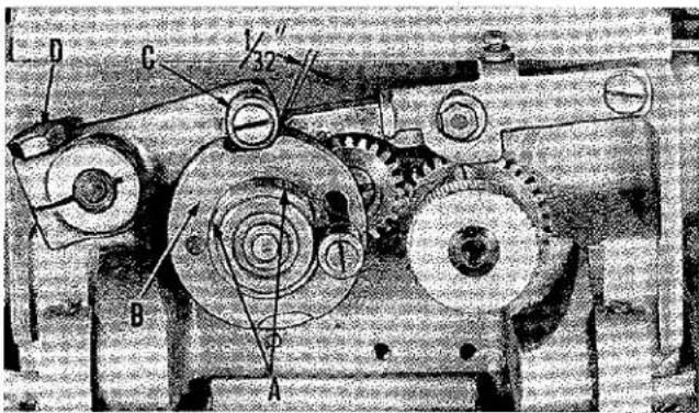
With the machine in stop position, loosen the two socket head set screws (A, Fig. 2) in stop motion cam (B) and rotate cam to secure 1/32 inch clearance between roller (C) and front of slot in cam.
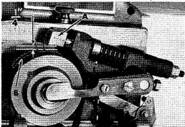
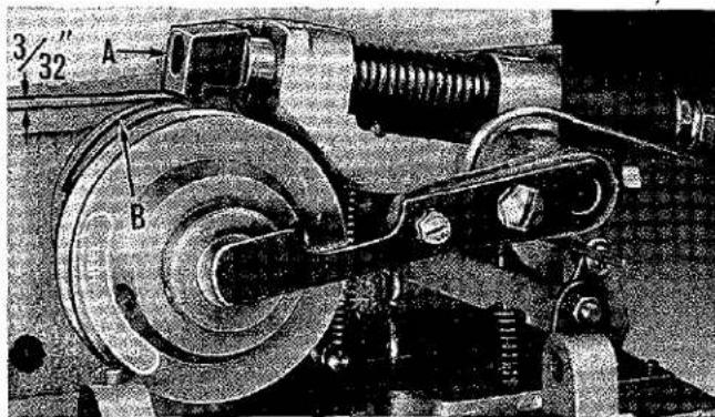
Depress the treadle to take machine out of stop position, and rotate pulley two complete revolutions in operating direction. Release treadle and measure distance between plunger (A, Fig. 3) and highest point on disc (B). The distance should be 3/32 inch.
text_image
D C 32 B AFig. 2
This adjustment is made by loosening clamp screw (D, Fig. 2) in stop motion trip lever and moving lever up or down to secure the 3/32 inch clearance. Should it be necessary to move lever down, depress the treadle while making adjustment.
ADJUSTING STOP MOTION (Continued)
Effective with Serial No. 1368377, an "improved" Stop Motion Cam and Gear Assembly has been incorporated, for which the following instructions apply:
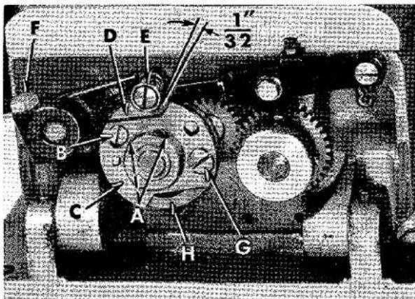
With the machine in stop position, loosen the two socket head set screws. (A, Fig. 2A) and screw (B). Rotate "left cam" (C) counterclockwise to the top of its elongated slot (as viewed in Fig. 2A) and tighten screw (B). Rotate cam (C) and "right cam" (D) as required to obtain 1/32 inch clearance between roller (E) and the front of slot in cam (D); tighten set screws (A).
NOTE: 1. This dimension MUST remain constant: regardless of other related or associated adjustments.
Depress the treadle to take machine out of stop position, then rotate pulley two complete revolutions in operating direction. Release treadle and measure the distance between plunger (A, Fig. 3A) and the highest point on disc (B). The distance should be 1/4 inch. Adjustment can be made by loosening clamp screw (F, Fig. 2A) in the stop motion trip lever and moving lever up or down to attain specified clearance. Should it become necessary to move the lever down, depress the treadle while making adjustment. Retighten clamp screw (F).
SOFT STOP ADJUSTMENT
Step 1. With the machine in stop position, loosen screws (A, Fig. 2A) and screw (B). Advance "left cam" (C) by rotating it clockwise, SLIGHTLY, relative to the "right cam" (D). Retighten screws (A and B) after referring to NOTE 1 above.
Step 2. Operate the machine and check the stop motion performance. When adjusted properly, the impact and noise will noticeably decrease when the machine stops. Should this condition still not exist, repeat Step 1.
Step 3. Should disc and pawl (K, Fig. 1) stop short of plunger (A), (this can be checked by rotating disc towards the operator and if the plunger does not catch the disc and pawl, the machine has not reached its stopped position), denoting cam is advanced beyond proper setting. To correct: retard "left cam" (C, Fig. 2A) by rotating it counterclockwise, SLIGHTLY, relative to the "right cam" (D). Refer to NOTE 1 above, before securing screws (A and B).
NOTE: 2. With reference to (A, Fig. 5) under "STITCH SETTINGS", the stitch adjusting knob has been replaced by screw (G, Fig. 2A) which secures cam shoe (H) using the upper or lower hole in "left cam" (C), as applicable.
text_image
F D E 1/3 2 B C A H CFig. 2A
text_image
Technical diagram of a mechanical device with labeled parts A and B, showing internal components and motion indicators.Fig. 3A
TIMING CAMS
Depress treadle to take machine out of stop position, and rotate pulley two complete revolutions in operating direction. Loosen knurled screw (J, Fig. 1) and lay machine on its side.
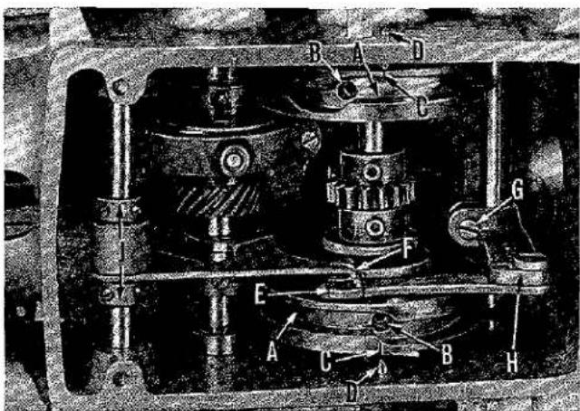
Turn pulley in operating direction until first screws in cams (A, Fig. 4) coming into view are accessible, and loosen these two screws. Continue to turn pulley in operating direction until machine is again in stop position and screws (B) are in view.
Loosen the two screws (B) and turn cams (A) in either direction to align timing lines (C) on cams with timing pins (D) in bed. Retighten all four cam screws securely.
text_image
3/32" A BFig. 3
ADJUSTING CLAMP LIFTING LINK
The button clamp lifting link (E, Fig. 4) is in proper position, when, with the machine in stop position, the lip on the fork lever (F) is engaged in the slot of the link.
Forward and backward adjustment of the link is accomplished by loosening clamp screw (G) in lever (H) and moving lever on shaft.
Adjustment of the fork lever (F) is made by loosening screws in collars (J) and moving fork lever on shaft.
COMBINATIONS OF STITCHES AVAILABLE
The cams and gears furnished with the Class 200 machines will produce 6, 12, or 24 stitches or 8, 16, or 32 stitches, depending on the Style. These combinations are obtained as follows:
text_image
Technical diagram of a mechanical device with labeled components A through H, showing internal components and structural connections.Fig. 4
-
With one half cycle of cam shaft, 6 or 8 stitches per button. Cannot be used for four hole buttons.
-
With one cycle of cam shaft, 12 or 16 stitches per button.
-
With two cycles of cam shaft, 24 or 32 stitches per button.
SETTING FOR SIX OR EIGHT STITCHES
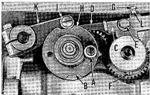
Figure 5 shows the machine in stop position, and set for 12 or 16 stitches. The stitch adjusting knob (A) is at its low
position at the bottom of the slot and the gap (B) is closed. To change to 6 or 8 stitches, simply pull out on the stitch adjusting knob (A) and raise it to the top of the slot. At this point, the gap (B) will be open.
SETTING FOR SIX OR EIGHT STITCHES (continued)
When setting for 6 or 8, or 12 or 16 stitches, the latch(C) must be set as high as possible in relation to the lever (D). To make this adjustment, loosen screw (E), hold lever (D) down, raise latch (C) as high as it will go, and retighten screw (E).
text_image
K J H D G L C E B A FFig. 5
SETTING FOR TWELVE OR SIXTEEN STITCHES
When changing from 6 or 8 to 12 or 16 stitches, the machine must be in stop position with the stitch adjusting knob (A, Fig. 5) towards the front. Pull out on the stitch adjusting knob (A) and move it to the bottom of its slot as shown in Fig. 5. Gap (B) will now be closed.
SETTING FOR TWENTY FOUR OR THIRTY TWO STITCHES
to 24 or 32 stitches, the machine must be in stop position with stitch adjusting knob (A, Fig. 5) to the front. If the machine is in the 6 or 8 stitch position, pull out on the stitch adjusting knob (A) and move it to the bottom of its slot. Check position of screw (F). It should be at the bottom as shown in Fig. 5. If it is not, the machine will have to be re-cycled once to bring screw (F) into proper position.
Loosen screw (E) and move latch (C) down as far as it will go. Retighten screw (E).
If, after this adjustment, the machine does not cycle properly, the position of the stop screw (G) must be adjusted. To do this, loosen screws (E and G) in latch (C). Turn pulley in operating direction until outside front corner of gap (H) is under the roller (J) and the screw (F) is at the top. Raise lever (D) against lever (K), move latch (C) down against screw (F), and tighten screw (E). Run screw (G) lightly down against lever (D) and lock with nut (L).
ADJUSTING NEEDLE BAR
When using short needles, use the upper pair of timing lines on the needle bar; for long needles, use the middle pair of timing lines; for extra long needles, use the lower pair.
Take machine out of stop position, and turn pulley two complete revolutions in operating direction.
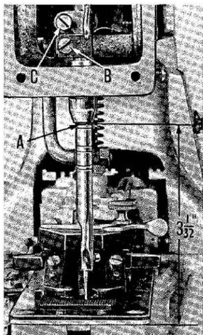
With the needle bar in its lowest position, the upper line of each pair of timing lines (A, Fig. 6), depending on which length of needle is used, should be even with the lower edge of the needle bar bushing.
text_image
A B C 3/32Fig. 6
To raise or lower needle bar, loosen needle bar clamp screw (B) and take-up clamp screw (C), move bar to desired height, and retighten screws. The take-up clamp must rest against the needle bar clamp.
The needle bar is correctly positioned when the needle set screw (D) enters the slot in the needle bar bushing freely.
ADJUSTING NEEDLE BAR (continued)
The position of the needle bar bushing is set to a gauge at the factory. The distance from its lower edge to the machined surface of the cylinder base is 3 1/32 inches.
ALIGNING FEED PLATE
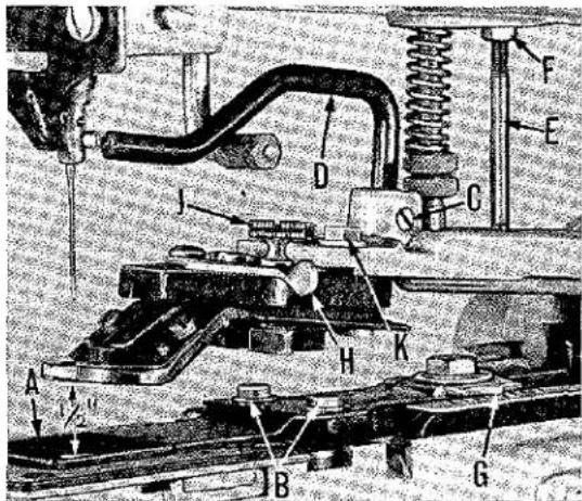
Make sure that the feed plate (A, Fig. 7) is set so that it does not interfere with the needle at any point of its travel.
Adjustment is made by loosening two screws (B) and moving feed plate to desired position.
TIMING NEEDLE WITH HOOK
NOTE: Fig. 8 shows the machine with needle plate, feed plate, and button clamp removed. This has been done for clarity only. These parts need not be removed to make the adjustments.
text_image
Technical diagram of a mechanical assembly with labeled components A through H, showing structural components and connections.Fig. 7
Take machine out of stop position, and rotate pulley two complete revolutions in operating direction. Lower the needle bar until it reaches its lowest position, then, raise it until the lower edge of the needle bar bushing is midway between the upper pair of timing lines on the bar when using short needles. (When the machine is equipped with long needles, use the lower pair of timing lines.)
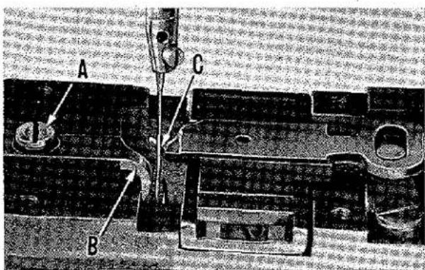
Loosen needle guard clamp screw (A, Fig. 8) and slide needle guard (B) forward. Insert a screw driver behind the loop positioning finger (C) and pull the finger forward. There should be only the slightest amount of clearance between the finger and needle, approximately .002 inch.
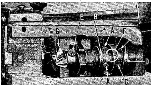
To make this adjustment, loosen set screws (A, Fig. 9) in the sleeve (B), slide sleeve forward slightly and retighten one of the screws enough to prevent the sleeve sliding on the shaft during adjustment. Now, loosen screws (C) in cam (D) and slide cam in the direction necessary to secure the proper clearance between the loop
positioning finger and the needle. Tighten one of the screws in the cam and slide the sleeve back so that it contacts the cam.
text_image
A B CFig. 8
Rotate the pulley in operating direction until the lower timing line on the needle bar is even with the lower edge of the needle bar bushing. Rotate the sleeve (B) so that the point of the hook is at the center of the needle on the back side and tighten both screws (A) in the sleeve. Loosen hook collar clamp screw (E), and slide hook (G) so that there is the smallest amount of clearance between its point and the needle, and retighten hook clamp screw. Loosen setscrew (C) in cam (D), and rotate cam so that its timing line coincides with the timing line on the sleeve (F). Tighten screws in cam, making sure that the cam is against the sleeve. Turn the pulley in operating direction until the needle bar is at its lowest position, and slide the needle guard (B, Fig. 8) in the direction of the needle until there is a clearance of about .002 inch between it and the needle. Retighten clamp screw (A) securely.
HEIGHT OF BUTTON CLAMP
With the machine in stop position, the normal distance between the bottom of the button clamp to the top of the feed plate should be 1/2 inch (Fig. 7). To make this adjustment, loosen set screw (C), and raise or lower rod (D).
text_image
E B G A F C D A CFig. 9
Take machine out of stop position, and turn pulley in operating direction until button clamp is in its furthest position to the rear. At this point, there must be clearance between the button clamp lifting rod (A, Fig. 10) and the button clamp lifting roller (B). Adjustment is made by loosening screw (C) and moving rod (A) up. This will affect the height of the button clamp in relation to the feed plate as previously described, but for the normal setting of 1/2 inch, no interference between lifting rod and roller will occur.
Return the machine to stop position, and check the position of the button clamp stop pin (E, Fig. 7). Its purpose is to prevent overthrow of the button clamp so that the needle will not strike the button or any other part of the button clamp. Insufficient clearance between the stop pin and the button clamp holder will cause the machine to re-cycle. Too much clearance will cause the button to strike the needle.
On Styles 200-16, 200-17, which are equipped with a tacking clamp instead of a button clamp, the tacking clamp should be set so that there is a distance of approximately 1/2 inch between it and the feed plate with machine in stop position. Position of the clamp can be changed by loosening lock nut and turning clamp rod in or out to desired height. The clampholder will have to be removed to make this adjustment.
The stop pin, corresponding to (E, Fig. 7), should be set only as low as necessary to drop the feed plate holder off the latch when the machine has reached stop position.
POSITIONING AND ADJUSTING BUTTON CLAMP
FOR FOUR HOLE BUTTONS
Accurately measure the distance between the holes of the button, and set the pivot indicator (G, Fig. 7) and spring indicator (A, Fig. 11) to the graduations corresponding to the distance between the holes in the button.
With the machine in stop position, insert the button in the jaws of the clamp, and adjust the stop lever (H, Fig. 7) by means of screw (J) so that the button is held loosely by the jaws.
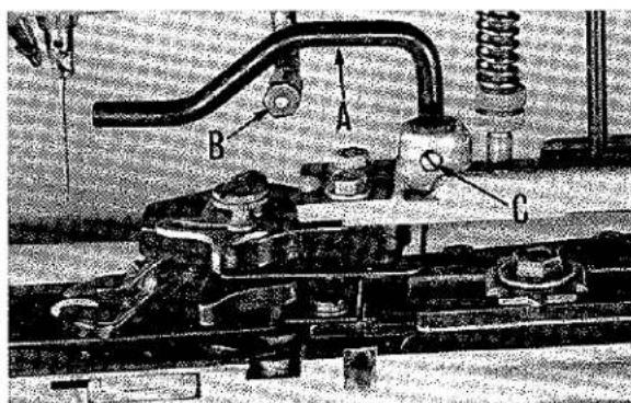
text_image
Technical diagram of a mechanical assembly with labeled parts A, B, and CFig. 10
Take the machine out of stop position, and turn slowly by hand to make sure that the needle enters the center of each hole in the button. The button clamp may have to be shifted slightly to secure this condition. Loosen screws (K) to make the adjustment.
The graduations on the indicator scales are only approximate, and it may be necessary to deviate slightly from them.
POSITIONING AND ADJUSTING BUTTON CLAMP (continued)
FOR TWO HOLE BUTTONS
Set pivot indicator (G, Fig. 7) to proper graduation on scale corresponding to distance between holes of button, and set spring indicator (A, Fig. 11) on circle with two dots at left end of scale (B). Continue with adjustment of button clamp the same as for four hole buttons.
When sewing two hole buttons from back to front on Styles 200-6, 200-7, set pivot indicator (G, Fig. 7) and spring indicator (A, Fig. 11) to the proper graduations on scales, corresponding to distance between holes of button. Push in the lever located under the spring indicator (A, Fig. 11). This lever is not illustrated.
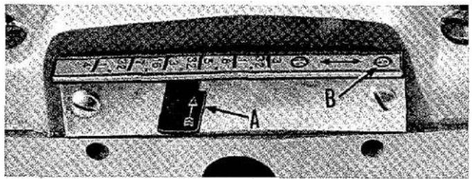
text_image
A BFig. 11
THREAD TENSION
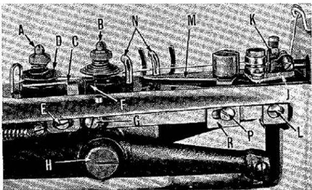
The regular thread tension (A, Fig. 12) is located behind the automatic thread tension (B) and controls the tightness of the button. The tension required will vary in relation to the types of thread, materials, and thickness of buttons used. Normally, only a light tension is required.
Take machine out of stop position, rotate pulley two complete turns in operating direction, and thread machine in accordance with threading diagram (Fig. 13).
Check the position of the tension releasing lever (C, Fig. 12) to see that it comes as close as possible to the tension discs (D) without contacting them. Adjustment is made by loosening screw (E) and moving the lever (C) in the required direction. In the illustration (Fig. 12), another tension releasing lever (F) is shown. This lever is used only on Style 200-10, and is adjusted in relation to the automatic tension discs in the same manner in which lever (C) is adjusted for the regular tension discs. Loosen screw (G) to make this adjustment.
text_image
Technical diagram of a mechanical device with labeled components A through L, showing assembly or assembly details.Fig. 12
AUTOMATIC THREAD TENSION
The automatic tension controls the tightness of the stitch on the under side of the fabric.
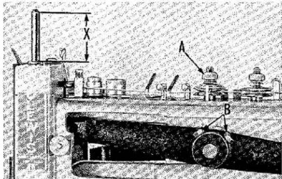
With the tension nut (A, Fig. 14) turned down about four or five turns, the automatic thread tension should release the thread when the needle bar, on its upstroke, has risen to a point where the lower edge of its bevelled top is 19/16 ± 1/32 inch above the top edge of the upper needle bar bushing as shown at dimension "X" (Fig. 14) on machines
using short needles. When using long needles, the needle bar must be allowed to rise until dimension "X" is 1 15/16 + 1/32 inch. For extra long needles, this dimension should be 2 1/8 + 1/32 inch.
To make this adjustment, turn pulley in operating direction until the needle bar has risen to the heights described above. Loosen the two hexagonal head screws (B) in needle lever hub and turn needle lever shaft (H, Fig. 12) with a screw driver until the tension releases.
text_image
THREADING AND OILING DIAGRAM FOR LEWIS CLASS 200 OIL GEAR OIL NEEDLE BAR REMOVE COVER AND OIL ALL WORKING PARTS GREASE HEREFig. 13
AUTOMATIC THREAD TENSION (continued)
Hold the needle lever shaft in this position while retightening the two hexagonal head screws (B, Fig. 14). This is an extremely important adjustment, and should be re-checked.
If, after re-checking, it is found that excessively large loops still exist on the underside of the fabric, the situation can be helped by applying more tension at tension nut (A, Fig. 14).
THREAD NIPPER
The thread nipper (J, Fig. 12) pinches and holds the thread so that the raising of the button clamp at the conclusion of the sewing cycle will break off the thread at the button. On Style 200-10, the thread nipper also pinches and holds the thread at the middle of the sewing cycle so that the knife can cut the cross-over stitch.
text_image
Technical diagram showing mechanical components with labeled parts A and B, and a dimension X indicated.Fig. 14
The thread nipper should be set so that there is 3/64 inch clearance between it and the nipper block (K) when the nipper is open. Loosen screw (L) and move the nipper (J) in the required direction to make the adjustment.
THREAD PULL-OFF LEVER
The thread pull-off lever (M, Fig. 12) controls the amount of thread which is pulled through the tensions, at the end of a stitching cycle, to provide sufficient thread for the first stitch of the following cycle.
With the machine out of stop position, there should be no contact between the pull-off lever (M) and the thread, when the thread is pulled taut against the thread guides (N).
text_image
B A C DFig. 15
This adjustment is made by loosening screw (P) and moving block (R) forward or back.
If, when sewing, too much thread tail is visible on the right side of a two hole button, or the right rear of a four hole button, move the pull-off lever to the right as described above.
If too much thread tail is visible on the left side of a two hole button, or the left rear of a four hole button, move the pull-off lever to the left.
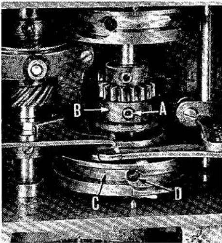
On Style 200-10, the pull-off lever has an additional adjustment which causes it to function in the middle of the cycle during the cutting of the cross-over stitch. Loosen three socket head screws (A, Fig. 15) in cam (B).
Place machine in stop position for starting point of subsequent adjustment.
Take machine out of stop position and turn pulley in operating direction until needle has entered feed plate seven times. Continue turning pulley until needle bar has risen to a point where the lower edge of its bevelled top is 1 7/8 inches from the top of the upper needle bar bushing (see dimension "X", Fig. 14).
THREAD PULL-OFF LEVER (continued)
Turn cam (B, Fig. 15) to the right, as you face it, until the lobe stops against the projection on the nipper operating link, and retighten three socket head screws (A).
text_image
A B AFig. 16
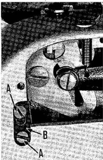
The length of thread tails on the front holes of buttons is controlled, on Style 200-10, by an additional adjustment to the pull-off lever.
If too much thread tail is visible on the right front hole, loosen screws (A, Fig. 16) and raise the link (B). For easier access to link, remove right side cover.
TIMING THE KNIFE
On Style 200-10, the knife should cut the cross-over stitch at the middle of the cycle.
Take machine out of stop position and turn pulley in operating direction until needle has entered feed plate eight times. Continue turning pulley until needle bar has risen to the top of its stroke. At exactly this point, the knife should snap out of operating position.
To make corrections to knife timing, place machine in stop position for starting subsequent adjustment. Take machine out of stop position and turn the pulley two complete revolutions in operating direction. Loosen knurled base clamping screw and lay machine on its side. Turn pulley in operating direction until the first screw in cam (C, Fig. 15) comes into view, and loosen this screw. Continue to turn pulley until machine is again in stop position, and loosen screw(D). Turn cam (A) slightly to right to speed up knife timing, and to the left to retard it. Tighten all screws securely.
The slight amount of adjustment required for this setting will have no noticeable effect on previous timing of the cams described on Page 9.
On Style 200-15, the knife should cut the thread at the end of the stitching cycle.
The knife should snap out of operating position when the needle bar has risen to within 1/16 inch of the top of the last up-stroke in the cycle.
Changes to timing are made in the same manner as described for Style 200-10.
POSITIONING THE KNIFE
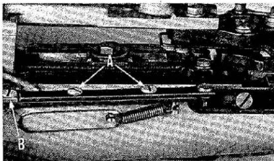
To position knife, loosen screws (A, Fig. 17), and move bar (B) in or out.
natural_image
Mechanical assembly diagram showing components labeled A and B, no readable text or symbols presentFig. 17
ORDERING REPAIR PARTS
ILLUSTRATIONS
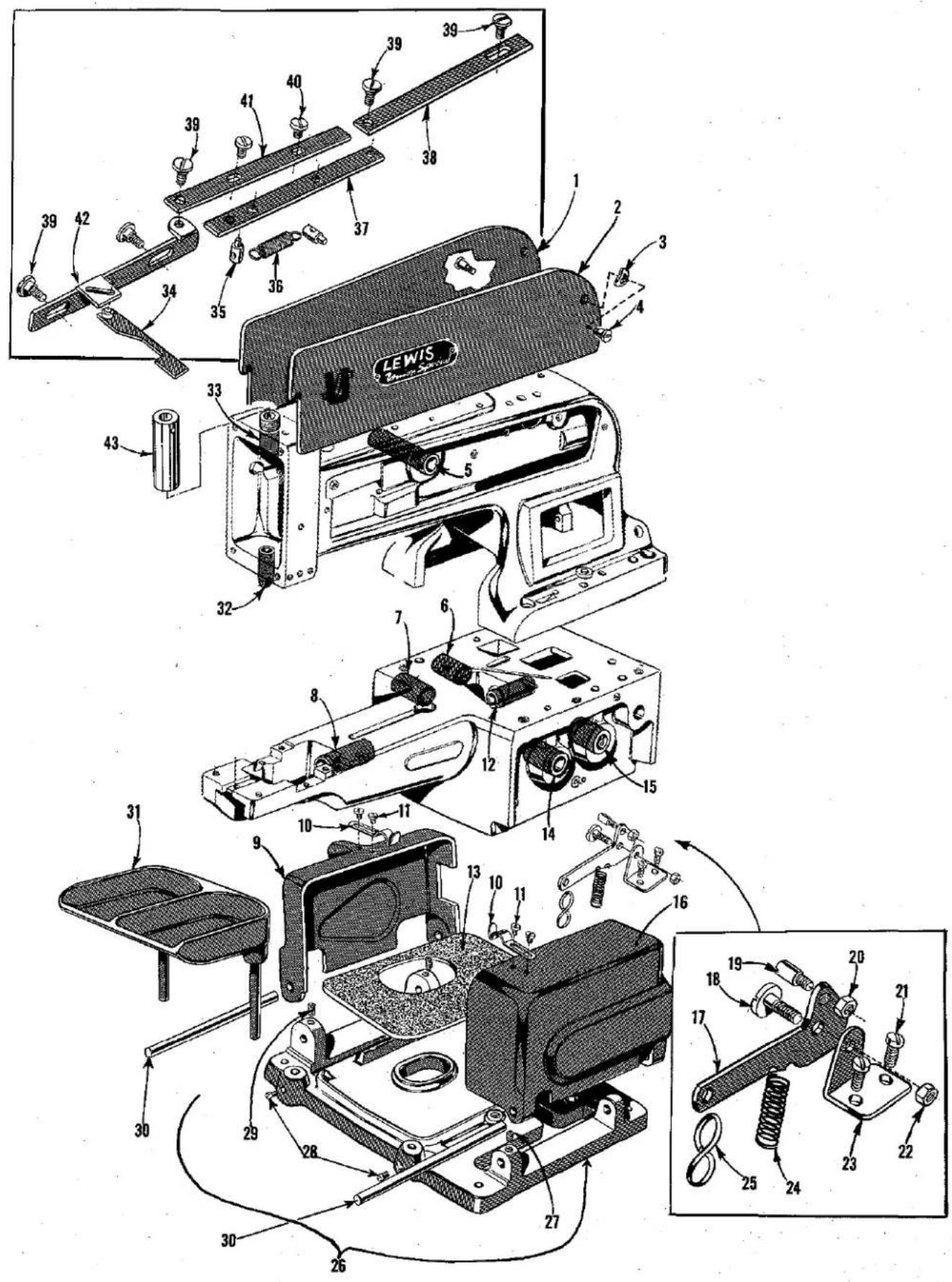
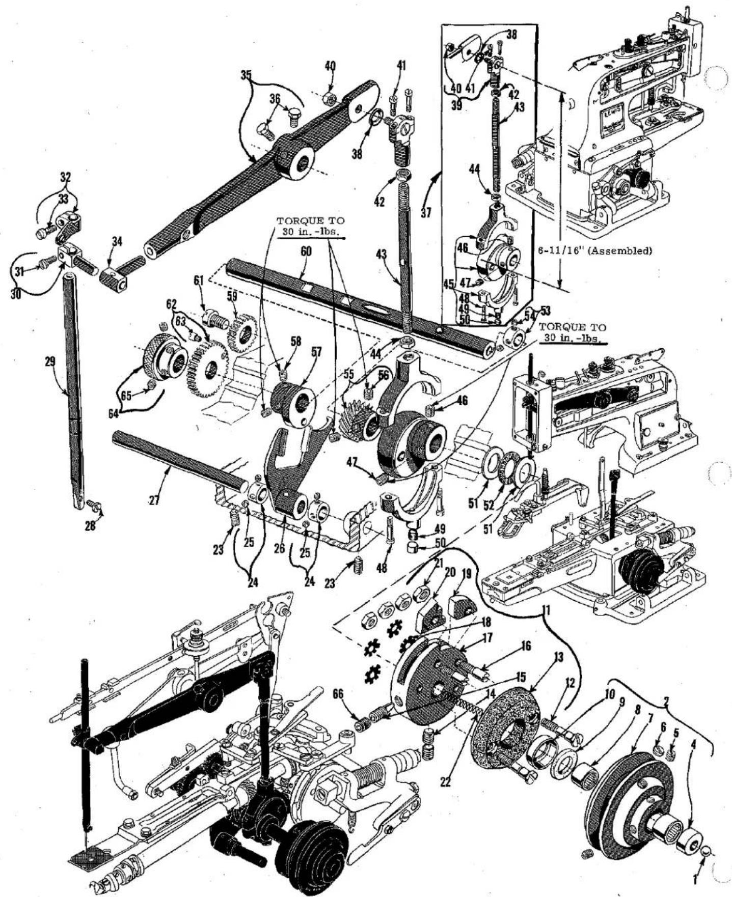
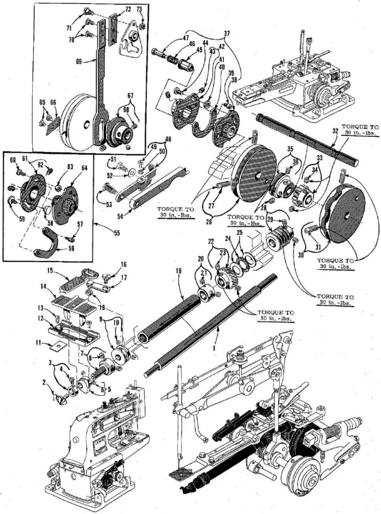
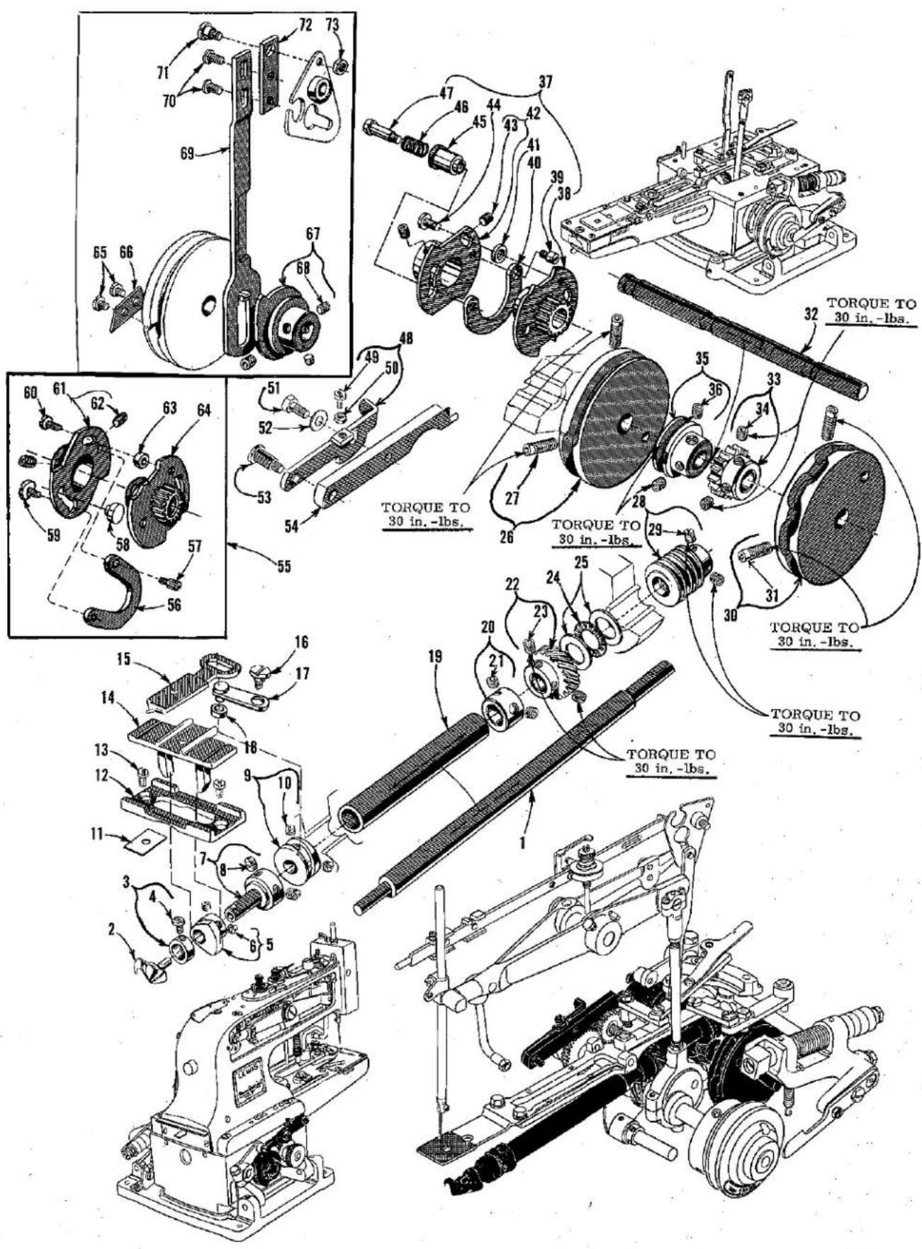
This catalog has been arranged to simplify ordering repair parts. Exploded views of various sections of the mechanism are shown so that the parts may be seen in their actual position in the machine. On the page opposite the illustration will be found a listing of the parts with their part number, description and the number of pieces required in the particular view being shown.
Numbers in the first column are reference numbers only, and merely indicate the position of that part in the illustration. Reference numbers should never be used in ordering parts. Always use the part number listed in the second column.
Component parts of sub-assemblies which can be furnished for repairs are indicated by indenting their descriptions under the description of the main sub-assembly. Example:
| 45 | 4124-49 | Ball Joint, lower, complete | 1 |
| 46 | 18-968 | Spot Screw | 1 |
| 47 | 18-730 | Set Screw | 1 |
| 48 | 18-925 | Screw | 2 |
| 49 | 666-19 | Oil Wick | 1 |
| 50 | 137-19 | Oil Wick Retainer | 1 |
It will be noted in the above example that the eccentric and strap are not listed. The reason is that replacement of these parts individually is not recommended, so the complete sub-assembly should be ordered.
At the back of the book will be found a numerical index of all the parts shown in this book. This will facilitate locating the illustration and description when only the part number is known.
IDENTIFYING PARTS
Where the construction permits, each part is stamped with its part number. Part numbers represent the same part, regardless of catalog in which they appear.
USE GENUINE REPAIR PARTS
Success in the operation of these machines can be secured only with genuine UNION SPECIAL Repair Parts as furnished by the Union Special Corporation, its subsidiaries and authorized distributors. They are designed according to the most approved scientific principles, and are made with utmost precision. Maximum efficiency and durability are assured.
TERMS
Prices are net cash and subject to change without notice. All shipments are forwarded f.o.b. shipping point. Parcel Post shipments are insured unless otherwise directed. A charge is made to cover postage and insurance.
text_image
Technical diagram of a mechanical assembly with numbered parts, including lewis and a base plate.BASE, COVERS, BUSHINGS
| Ref.No. | PartNo. | Description | Amt.Req. |
| 1 | 432-306 | Arm Cover, left | 1 |
| 2 | 432-305 | Arm Cover, right | 1 |
| 3 | 12957 E | Washer | 2 |
| 4 | 1220 L | Screw | 2 |
| 5 | 16-412 | Needle Lever Shaft Bushing | 1 |
| 6 | 16-291 | Cam Shaft Bushing, left | 1 |
| 7 | 16-289 | Pulley Shaft Bushing, left | 1 |
| 8 | 16-292 | Looper Shaft Bushing, front | 1 |
| 9 | 32-192 | Cover, left | 1 |
| 10 | 21-295 | Spring | 2 |
| 11 | CS337 | Screw | 4 |
| 12 | 16-334 | Looper Shaft Bushing, rear | 1 |
| 13 | 144-25 | Felt Pad | 1 |
| 14 | 16-288 | Pulley Shaft Bushing, right | 1 |
| 15 | 16-398 | Cam Shaft Bushing, right | 1 |
| 16 | 32-191 | Stop Motion and Pulley Cover, right | 1 |
| 17 | 45-333 | Stop Motion Trip Lever | 1 |
| 18 | 1235 L | Screw | 1 |
| 19 | 787 L | Stop Screw | 1 |
| 20 | 1160 L | Nut | 1 |
| 21 | 1158 L | Screw | 2 |
| 22 | 1009 L | Nut | 1 |
| 23 | 50-215 | Bracket | 1 |
| 24 | 21-321 | Spring | 1 |
| 25 | 131-C163-2 | "S" Chain Hook | 1 |
| 26 | 141-4 | Machine Sub-Base | 1 |
| 27 | 1005 L | Set Screw | 1 |
| 28 | 18-738 | Screw | 2 |
| 29 | 1003 L | Set Screw | 2 |
| 30 | 14-399 | Hinge Shaft | 2 |
| 31 | 4186-16 | Button Tray, complete, for Styles 200-1,-2,-6,-7,-8,-9,-10,-25,-26,-27 | 1 |
| 32 | 16-297 | Needle Bar Bushing, lower | 1 |
| 33 | 16-411 | Needle Bar Bushing, upper | 1 |
| 34 | 4119-86 | Thread Cutting Knife, complete, for Styles 200-10-15 | 1 |
| 35 | 22-255 | Spring Pin, for Styles 200-10,-15 | 2 |
| 36 | 21-96 | Spring, for Styles 200-10,-15 | 1 |
| 37 | 46-182 | Thread Cutting Lever Link, bottom, for Styles 200-10,-15 | 1 |
| 38 | 46-183 | Thread Cutting Cam Link, for Styles 200-10,-15 | 1 |
| 39 | 18-1035 | Screw, for Styles 200-10,-15 | 5 |
| 40 | CS337 | Screw, for Styles 200-10,-15 | 2 |
| 41 | 46-181 | Thread Cutting Lever Link, top, for Styles 200-10,-15 | 1 |
| 42 | 45-426 | Thread Cutting Knife Lever, for Styles 200-10,-15 | 1 |
| 43 | 75-267 | Needle Bar Guard | 1 |
text_image
TORQUE TO 30 in. -Ibs. 6-11/16" (Assembled) TORQUE TO 30 in. -Ibs.NEEDLE DRIVE, CLUTCH, STOP MOTION PARTS
| Ref. No. | Part No. | Description | Amt. Req. |
| 1 | 79-37 | Ball---- | 1 |
| 2 | 458-39 | Pulley Assembly, complete---- | 1 |
| 4 | 190-2 L | Pulley Insert---- | 1 |
| 5 | 1005 L | Set Screw---- | 2 |
| 6 | 18-800 | Set Screw---- | 1 |
| 7 | 58-39 | Pulley---- | 1 |
| 8 | 478-10 | Needle Bearing---- | 2 |
| 9 | 63-32 | Grease Retaining Wick---- | 1 |
| 10 | 40-169 | Retaining Washer---- | 1 |
| 11 | 444-334 | Stop Disc, complete---- | 1 |
| 12 | 18-982 | Screw---- | 2 |
| 13 | 44-288 | Pulley Clutch Disc---- | 1 |
| 14 | 18-967 | Set Screw---- | 1 |
| 15 | 18-958 | Spot Screw---- | 1 |
| 16 | 18-959 | Screw---- | 2 |
| 17 | 44-334 | Stop Motion Disc---- | 1 |
| 18 | 652 N-14 | Eccentric Washer---- | 4 |
| 19 | 51-20 | Stop Motion Disc Latch---- | 1 |
| 20 | 166-7 | Stop Motion Disc Pawl---- | 1 |
| 21 | 20-127 | Nut---- | 4 |
| 22 | 21-229 | Spring---- | 1 |
| 23 | 1003 L | Set Screw---- | 2 |
| 24 | CS462 | Collar---- | 2 |
| 25 | 1022 L | Set Screw---- | 2 |
| 26 | 445-298 | Lever Engaging Button Clamp Lifting Link---- | 1 |
| 27 | 14-362 | Lever Shaft---- | 1 |
| 28 | 18-272 | Screw---- | 1 |
| *18-725 | Set Screw, headless, for needle longer than our longest standard,or needle bar turned 180°---- | 1 | |
| 29 | 25-11 | Needle Bar---- | 1 |
| 30 | 117-40 | Needle Bar Bearing Block Clamp---- | 1 |
| 31 | 18-71 | Screw---- | 1 |
| 32 | 41-47 | Needle Bar Thread Guide---- | 1 |
| 33 | 18-907 | Screw---- | 1 |
| 34 | 117-39 | Needle Bar Bearing Block---- | 1 |
| 35 | 45-335 A | Needle Bar Lever---- | 1 |
| 36 | 1333 L | Set Screw---- | 2 |
| 37 | 447-105 | Needle Bar Connecting Rod, complete---- | 1 |
| 38 | 40-63 | Washer---- | 1 |
| 39 | 4124-50 | Ball Joint, upper, complete---- | 1 |
| 40 | 1009 L | Nut---- | 1 |
| 41 | 18-391 | Screw---- | 2 |
| 42 | 20-80 | Nut---- | 1 |
| 43 | 71-74 | Rod---- | 1 |
| 44 | 20-81 | Nut---- | 1 |
| 45 | 4124-49 | Ball Joint, lower, complete---- | 1 |
| 46 | 18-968 | Spot Screw---- | 1 |
| 47 | 18-730 | Set Screw---- | 1 |
| 48 | 18-925 | Screw---- | 2 |
| 49 | 666-19 | Oil Wick---- | 1 |
| 50 | 137-19 | Oil Wick Retainer---- | 1 |
| 51 | 40-135 | Washer---- | 2 |
| 52 | 478-27 | Needle Thrust Bearing---- | 1 |
| 53 | 2339 F | Thrust Collar---- | 1 |
| 54 | 98 | Set Screw---- | 2 |
| 55 | 27-169 | Driving Gear, for looper shaft---- | 1 |
| 56 | 18-996 | Set Screw---- | 2 |
| 57 | 433-139 | Button Clamp Lifting Link Lever Driving Eccentric, complete---- | 1 |
| 58 | 1005 L | Set Screw---- | 2 |
| 59 | 27-171 | Intermediate Spur Gear, for Styles 200-1,-2,-6,-7,-8,-9,-21,-22,-23,-24,-25,-27---- | 1 |
| Pulley Shaft---- | 1 | ||
| 60 | 14-363 | Screw, for Styles 200-1,-2,-6,-7,-8,-9,-21,-22,-23,-24,-25,-27---- | 1 |
| 61 | 18-878 | Spur Gear, for Styles 200-1,-2,-6,-7,-8,-9,-21,-22,-23,-24,-25,-27-- | 1 |
| 62 | 27-170 | Screw---- | 1 |
| 63 | 18-39 | Handwheel---- | 1 |
| 64 | 57-23 | Set Screw---- | 2 |
| 65 | 1025 L | ||
| 66 | 18-967 | Set Screw---- | 2 |
* Available as extra send and charge item.
text_image
Technical diagram of mechanical assembly with numbered parts and torque specifications in inches and lbs.CAMS, LOOPER DRIVE STITCH SELECTING PARTS
| Ref.No. | PartNo. | Description | Amt.Req. |
| 1 | 14-366 | Looper Shaft ---- | 1 |
| 2 | 36-21 | Looper ---- | 1 |
| 3 | 39-143 | Collar ---- | 1 |
| 4 | 18-949 | Looper Clamping Screw ---- | 1 |
| 5 | 434-40 | Loop Positioning Finger Cam, complete ---- | 1 |
| 6 | 18-634 | Screw ---- | 2 |
| 7 | 70-50 | Cam and Looper Sleeve ---- | 1 |
| 8 | 1005 L | Set Screw ---- | 2 |
| 9 | 34-47 | Loop Positioning Finger Cam ---- | 1 |
| 10 | 1029 L | Set Screw ---- | 2 |
| 11 | 164-39 | Shim, .005 inch (.127 mm) thick ---- As | Req. |
| 164-40 | Shim, .010 inch (.254 mm) thick ---- As | Req. | |
| 164-41 | Shim, .015 inch (.381 mm) thick ---- As | Req. | |
| 12 | 190-3 L | Yoke Slide Insert ---- | 1 |
| 13 | 18-949 | Screw ---- | 2 |
| 14 | 49-25 | Positioning Finger Yoke Slide, for Styles 200-1, -2, -6, -7,-8, -9, -16, -17, -21, -22, -23, -24, -25, -26, -27 ---- | 1 |
| 49-33 | Positioning Finger Yoke Slide, for Styles 200-10, -15 ---- | 1 | |
| 15 | 122-58 | Loop Positioning Finger ---- | 1 |
| 16 | 18-934 | Screw ---- | 1 |
| 17 | 445-349 | Loop Positioning Finger Lever ---- | 1 |
| 18 | 35-20 | Loop Positioning Finger Lever Roll ---- | 1 |
| 19 | 61-80 | Looper Shaft Tube ---- | 1 |
| 20 | 39-131 | Looper Shaft Collar ---- | 1 |
| 21 | 18-996 | Set Screw ---- | 2 |
| 22 | 27-168 | Looper Shaft Driven Gear ---- | 1 |
| 23 | 18-996 | Set Screw ---- | 2 |
| 24 | 478-27 | Needle Thrust Bearing ---- | 1 |
| 25 | 40-135 | Washer ---- | 2 |
| 26 | Cam, left side (See Chart Below) ---- | 1 | |
| 27 | 18-984 | Set Screw ---- | 2 |
| 28 | Driving Gear, for camshaft (See Chart Below) ---- | 1 | |
| 29 | 18-996 | Set Screw ---- | 2 |
| 30 | Cam, right side (See Chart Below) ---- | 1 | |
| 31 | 18-984 | Set Screw ---- | 2 |
| 32 | 14-364 | Camshaft ---- | 1 |
| 33 | Camshaft Driven Gear (See Chart Below) ---- | 1 | |
| 34 | 18-996 | Set Screw ---- | 2 |
| 35 | 39-107 | Collar ---- | 1 |
| 36 | 18-730 | Set Screw ---- | 2 |
| 37 thru 73 | See following page |
| STYLE NO. | DET. 33 Driven | DET. 28 Driving |
| 200-1 | 27-155 | 27-189 |
| 200-2 | 27-191 | 27-190 |
| 200-6 | 27-155 | 27-189 |
| 200-7 | 27-191 | 27-190 |
| 200-8 | 27-155 | 27-189 |
| 200-9 | 27-191 | 27-190 |
| 200-10 | 27-155 | 27-189 |
| 200-15 | 27-155 | 27-189 |
| 200-16 | 27-155 | 27-189 |
| 200-17 | 27-191 | 27-190 |
| 200-21 | 27-155 | 27-189 |
| 200-22 | 27-191 | 27-190 |
| 200-23 | 27-155 | 27-189 |
| 200-24 | 27-191 | 27-190 |
| 200-25 | 27-155 | 27-189 |
| 200-26 | 27-226 | 27-225 |
| 200-27 | 27-155 | 27-189 |
| STYLE NO. | DET. 26 Left | DET. 30 Right |
| 200-1 | 34-35 | 34-53 |
| 200-2 | 34-35 | 34-54 |
| 200-6 | 34-71 | 34-53 |
| 200-7 | 34-73 | 34-54 |
| 200-8 | 34-68 | 34-35 |
| 200-9 | 34-69 | 34-35 |
| 200-10 | 34-75 | 34-53 |
| 200-15 | 34-91 | 34-53 |
| 200-16 | 34-81 | None |
| 200-17 | 34-82 | None |
| 200-21 | 34-71 | 34-53 |
| 200-22 | 34-73 | 34-54 |
| 200-23 | 34-35 | 34-53 |
| 200-24 | 34-35 | 34-54 |
| 200-25 | 34-35 | 34-95 |
| 200-26 | 34-35 | 34-96 |
| 200-27 | 34-35 | 34-53 |
text_image
Technical diagram of mechanical assembly with numbered parts and torque annotations in inches and poundsCAMS, LOOPER DRIVE, STITCH SELECTING PARTS
| Ref.No. | PartNo. | Description | Amt.Req. |
| 1 thru 36 | See preceding page | ||
| 37 | 434-104 | Stop Motion Cam and Gear Assembly, complete with shoe and knob, for Styles 200-1, -2, -6, -7, -16, -21,-23, -24, -26, -27 | 1 |
| 38 | 434-101 | Cam and Gear Assembly, right | 1 |
| 39 | 18-39 | Screw | 1 |
| 40 | 180-4 | Cam Shoe | 1 |
| 41 | 39-151 | Collar, spacing | 1 |
| 42 | 34-104 | Cam, left | 1 |
| 43 | 18-730 | Screw | 2 |
| 44 | 22585 A | Screw | 1 |
| 45 | 142-6 | Knob | 1 |
| 46 | 21-322 | Spring | 1 |
| 47 | 18-835 | Screw | 1 |
| 48 | 51-22 | Latch, for Styles 200-1, -2, -6, -7, -8, -9, -21, -22,-23, -24, -25, -27 | 1 |
| 49 | 1170 L | Screw | 1 |
| 50 | 1311 L | Nut | 1 |
| 51 | 18-629 | Screw, for Styles 200-1, -2, -6, -7, -8, -9, -21, -22,-23, -24, -25, -27 | 1 |
| 52 | 40-38 | Washer, for Styles 200-1, -2, -6, -7, -8, -9, -21, -22,-23, -24, -25, -27 | 1 |
| 53 | 18-619 | Screw, for Styles 200-1, -2, -6, -7, -8, -9, -21, -22,-23, -24, -25, -27 | 1 |
| 54 | 45-331 | Lever, for Styles 200-1, -2, -6, -7, -8, -9, -21, -22,-23, -24, -25, -27 | 1 |
| 55 | 434-102 | Stop Motion Cam and Gear Assembly, complete with shoefor Styles 200-8, -9, -10, -15, -17, -22, -25 | 1 |
| 56 | 180-4 | Cam Shoe | 1 |
| 57 | 18-39 | Screw | 1 |
| 58 | 89-65 | Filling Plug | 1 |
| 59 | 18-1112 | Screw | 1 |
| 60 | 22585 A | Screw | 1 |
| 61 | 34-104 | Cam, left | 1 |
| 62 | 18-730 | Screw | 2 |
| 63 | 39-151 | Collar, spacing | 1 |
| 64 | 434-101 | Cam and Gear Assembly, right | 1 |
| 65 | CS337 | Screw, for Style 200-10, -15 | 2 |
| 66 | 166-11 | Thread Cutter Operating Pawl, for Styles 200-10, -15 | 1 |
| 67 | 34-65 | Nipper Bar Operating Cam, for Style 200-10 | 1 |
| 68 | 18-996 | Set Screw | 3 |
| 69 | 46-168 | Nipper Bar Operating Link, lower, for Style 200-10 | 1 |
| 70 | 18-330 | Screw, for Style 200-10 | 2 |
| 71 | 861 L | Screw, for Style 200-10 | 1 |
| 72 | 46-169 | Nipper Bar Operating Link, upper, for Style 200-10 | 1 |
| 73 | 1160 L | Nut, for Style 200-10 | 1 |
text_image
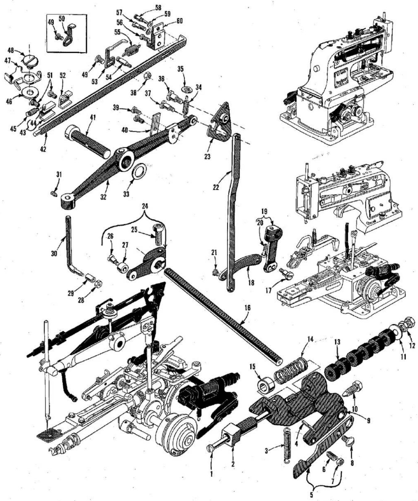
Technical diagram of mechanical assembly with numbered parts, likely a vehicle or engine assembly.BUTTON CLAMP LIFTER, STOP MOTION, NIPPER PARTS
| Ref. No. | Part No. | Description | Amt. Req. |
| 1 | 71-92 | Stop Motion Plunger Rod | 1 |
| 2 | 26-163 | Stop Motion Plunger | 1 |
| 3 | 21-360 | Stop Motion Lever Restoring Spring | 1 |
| 4 | 22-266 | Stop Motion Lever Restoring Spring Pin | 1 |
| 5 | 45-490 | Lever for Applying Pressure on Stop Motion Disc | 1 |
| 6 | 18-747 | Spot Screw | 1 |
| 7 | 20-34 | Nut | 1 |
| 8 | 18-280 | Screw | 1 |
| 9 | 45-348 | Stop Motion Plunger Lever | 1 |
| 10 | 18-819 | Screw | 1 |
| 11 | 652-16 | Washer | 1 |
| 12 | 20-128 | Nut | 2 |
| 13 | 40-198 | Washer | 6 |
| 14 | 21-457 | Spring | 1 |
| 15 | 157-13 | Spacer Collar | 1 |
| 16 | 14-365 | Stop Motion Lever Shaft for Styles 200-1, -2, -6, -7, -8, -9, -16, -17, -21, -22, -23, -24, -25, -26, -27 | 1 |
| 14-488 | Stop Motion Lever Shaft for Styles 200-10, -15 | 1 | |
| 17 | 18-392 | Screw | 1 |
| 18 | 46-135 | Link for Styles 200-1, -2, -8, -9, -15, -16, -17, -23, -24, -25, -26, -27 | 1 |
| 46-175 | Link for Styles 200-6, -7, -10, -21, -22 | 1 | |
| 19 | 445-286 | Lever, complete, engaging button clamp lifting link | 1 |
| 20 | 22653 B-10 | Clamp Screw | 1 |
| 21 | 18-809 | Screw | 1 |
| 22 | 46-162 | Button Clamp Lifting Link | 1 |
| 23 | 445-405 | Nipper Bar Actuating Lever | 1 |
| 24 | 445-370 | Stop Motion Tripping Lever | 1 |
| 25 | 22653 E-14 | Clamp Screw | 1 |
| 26 | CS303-1/2 | Screw | 1 |
| 27 | 35-16 | Stop Motion Tripping Lever Cam Roll | 1 |
| 28 | 835 L | Nut | 1 |
| 29 | 35-17 | Button Clamp Lifting Rod Roll | 1 |
| 30 | 71-124 | Button Clamp Lifting Rod | 1 |
| 31 | 22651 ED-6 | Set Screw | 1 |
| 32 | 45-503 | Button Clamp Lifting Lever | 1 |
| 33 | 40-143 | Washer | 1 |
| 34 | 21-96 | Spring | 1 |
| 35 | 40-168 | Washer | 1 |
| 36 | 18-562 | Screw | 1 |
| 37 | 18-619 | Screw | 1 |
| 38 | 835 L | Nut | 1 |
| 39 | 18-732 | Screw | 2 |
| 40 | 42-34 | Button Clamp Lifting Lever Stop | 1 |
| 41 | 14-368 | Button Clamp Lifting Lever Shaft | 1 |
| 42 | 138-15 | Nipper Bar | 1 |
| 43 | 4115-104 | Nipper Bar Block, complete | 1 |
| 44 | 22-235 | Spring Pin | 1 |
| 45 | 21-366 | Spring | 1 |
| 46 | 60038 K | Washer | 1 |
| 47 | 4187-3 | Thread Nipper | 1 |
| 48 | 18-1088 | Screw | 1 |
| 49 | 18-745 | Screw | 1 |
| 50 | 45-404 | Automatic Tension Opening Lever for Style 200-10 | 1 |
| 51 | 18-745 | Screw | 2 |
| 52 | 115-106 | Nipper Bar Block | 1 |
| 53 | 45-327 | Thread Tension Release Lever | 1 |
| 54 | 18-827 | Spring Screw | 1 |
| 55 | 21-379 | Nipper Bar Spring | 1 |
| 56 | 1158 L | Screw | 1 |
| 57 | 1206 L | Screw | 1 |
| 58 | 18-826 | Screw | 1 |
| 59 | 1185 L | Washer | 2 |
| 60 | 115-175 | Nipper Bar Bearing Block | 1 |
text_image
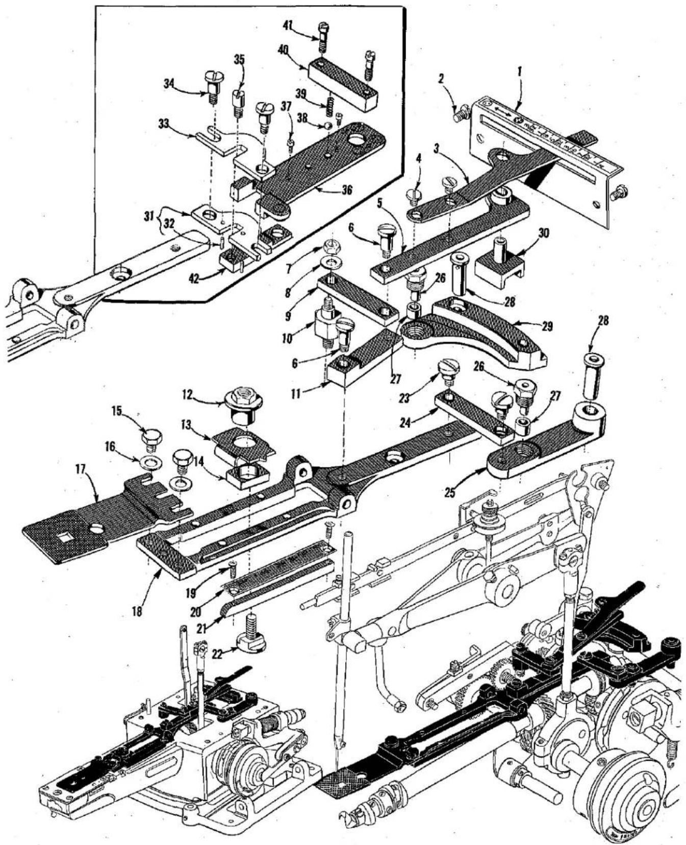
Technical diagram of a mechanical assembly with numbered components for identification and assembly reference.FEED PLATE AND BUTTON CLAMP POSITIONING PARTS
| Ref.No. | PartNo. | Description | Amt.Req. |
| 1 | 110-206 | Graduated Plate for Styles 200-1, -2, -10, -15, -23, -24, -25, -26, -27 | 1 |
| 110-318 | Graduated Plate for Styles 200-8, -9, -16, -17 | 1 | |
| 110-328 | Graduated Plate for Styles 200-6, -7, -21, -22 | 1 | |
| 2 | 18-330 | Screw | 2 |
| 3 | 21-287 | Handle and Indicator Spring | 1 |
| 4 | CS337 | Screw | 2 |
| 5 | 446-136 | Link | 1 |
| 6 | 18-619 | Screw | 2 |
| 7 | 1160 L | Nut | 1 |
| 8 | 40-38 | Washer | 1 |
| 9 | 46-137 | Link | 1 |
| 10 | 17-124 | Stud | 1 |
| 11 | 46-138 | Link | 1 |
| 12 | 20-109 | Nut for Styles 200-1, -2, -6, -7, -8, -9, -10, -15, -21, -22, -23, -24, -25, -26, -27 | 1 |
| 20-109 | Nut for Styles 200-16, -17 | 2 | |
| 13 | 155-14 | Indicator for Styles 200-1, -2, -6, -7, -8, -9, -10, -15, -21, -22, -23, -24, -25, -26, -27 | 1 |
| 155-14 | Indicator for Styles 200-16, -17 | 2 | |
| 14 | 69-17 | Bearing Block for Styles 200-1, -2, -6, -7, -8, -9, -10, -15, -21, -22, -23, -24, -25, -26, -27 | 1 |
| 69-17 | Bearing Block for Styles 200-16, -17 | 2 | |
| 15 | 18-626 | Screw for Styles 200-1, -2, -6, -7, -8, -9, -10, -15, -21, -22, -23, -24, -25, -26, -27 | 2 |
| 16 | 40-38 | Washer for Styles 200-1, -2, -6, -7, -8, -9, -10, -15, -21, -22, -23, -24, -25, -26, -27 | 2 |
| 17 | 24-338 | Feed Plate for Styles 200-1, -2, -6, -7, -8, -9, -10, -15, -23, -24, -25, -26 | 1 |
| 24-281 | Feed Plate, for Style 200-27 | 1 | |
| 18 | 158-29 | Slide Plate for Styles 200-1, -2, -10, -15, -23, -24, -25, -26, -27 | 1 |
| 158-17 | Slide Plate for Styles 200-16, -17 | 1 | |
| 158-19 | Slide Plate for Styles 200-6, -7, -8, -9, -10, -15, -21, -22 | 1 | |
| 19 | 18-966 | Screw for Styles 200-1, -2, -6, -7, -8, -9, -10, -15, -21, -22, -23, -24, -25, -26, -27 | 2 |
| 20 | 110-205 | Graduated Plate for Styles 200-1, -2, -6, -7, -8, -9, -10, -15, -21, -22, -23, -24, -25, -26, -27 | 1 |
| 21 | 115-108 | Block for Styles 200-1, -2, -6, -7, -8, -9, -10, -15, -21, -22, -23, -24, -25, -26, -27 | 1 |
| 22 | 18-818 | Screw for Styles 200-1, -2, -6, -7, -8, -9, -10, -15, -21, -22, -23, -24, -25, -26, -27 | 1 |
| 18-818 | Screw for Styles 200-16, -17 | 2 | |
| 23 | 18-392 | Screw for Styles 200-1, -2, -10, -15, -23, -24, -25, -26, -27 | 2 |
| 24 | 46-137 | Link for Styles 200-1, -2, -10, -15, -23, -24, -25, -26, -27 | 1 |
| 25 | 45-290 | Lever for Styles 200-1, -2, -6, -7, -8, -9, -10, -15, -21, -22, -23, -24, -25, -26, -27 | 1 |
| 26 | 18-814 | Screw for Styles 200-1, -2, -6, -7, -8, -9, -10, -15, -21, -22, -23, -24, -25, -26, -27 | 2 |
| 18-814 | Screw for Styles 200-16, -17 | 1 | |
| 27 | 35-15 | Cam Roll for Styles 200-1, -2, -6, -7, -8, -9, -10, -15, -21, -22, -23, -24, -25, -26, -27 | 2 |
| 35-15 | Cam Roll for Styles 200-16, -17 | 1 | |
| 28 | 22-219 | Pin for Styles 200-1, -2, -6, -7, -8, -9, -10, -15, -21, -22, -23, -24, -25, -26, -27 | 2 |
| 22-219 | Pin for Styles 200-16, -17 | 1 | |
| 29 | 45-288 | Lever for Styles 200-1, -2, -15, -16, -17, -23, -24, -25, -26, -27 | 1 |
| 45-416 | Lever for Styles 200-6, -7, -8, -9, -10, -21, -22 | 1 | |
| 30 | 69-16 | Slide Block | 1 |
| 31 | 446-173 | Bottom Link, complete, for Styles 200-6, -7, -8, -9, -21, -22 | 1 |
| 32 | 22-C214-13 | Pin | 2 |
| 33 | 46-173 | Top Link for Styles 200-6, -7, -8, -9, -21, -22 | 1 |
| 34 | 18-1023 | Screw for Styles 200-6, -7, -8, -9, -21, -22 | 2 |
| 35 | 18-1022 | Screw for Styles 200-6, -7, -8, -9, -21, -22 | 1 |
| 36 | 4110-329 | Slide Plate for Styles 200-6, -7, -21, -22 | 1 |
| 4110-317 | Slide Plate for Styles 200-8, -9 | 1 | |
| 37 | 1036 L | Stop Screw for Styles 200-6, -7, -8, -9, -21, -22 | 2 |
| 38 | 79-31 | Ball for Styles 200-6, -7, -8, -9, -21, -22 | 1 |
| 39 | 21-300 | Spring for Styles 200-6, -7, -8, -9, -21, -22 | 1 |
| 40 | 115-137 | Block for Styles 200-6, -7, -8, -9, -21, -22 | 1 |
| 41 | 18-766 | Screw for Styles 200-6, -7, -8, -9, -21, -22 | 2 |
| 42 | 46-174 | Link for Styles 200-6, -7, -8, -9, -21, -22 | 1 |
text_image
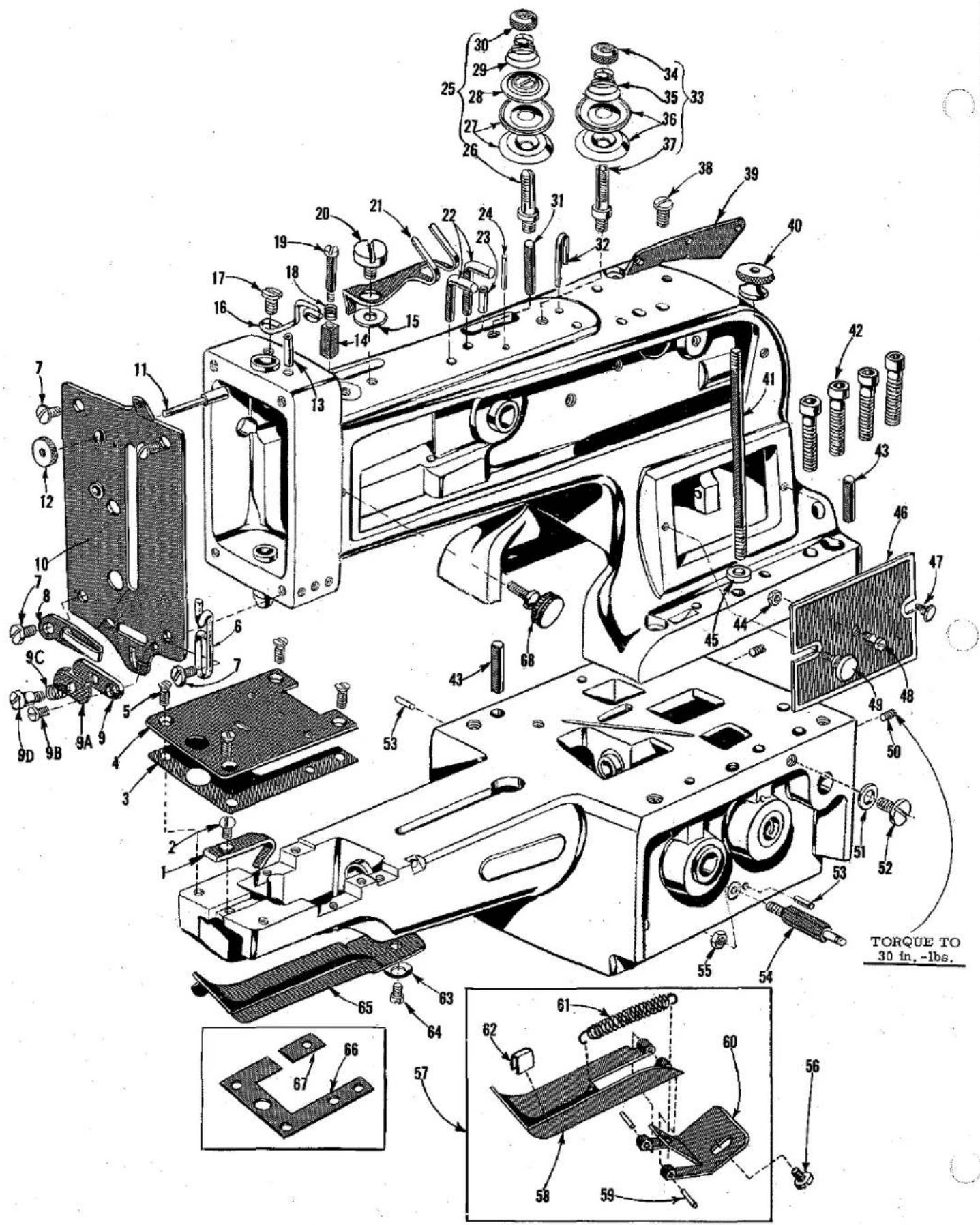
Technical diagram of a mechanical assembly with numbered components and torque specifications in ChineseMISCELLANEOUS PLATES, THREAD HANDLING PARTS
| Ref.No. | PartNo. | Description | Amt.Req. |
| 1 | 8-111 | Needle Guard---- | 1 |
| 2 | 18-750 | Screw---- | 1 |
| 3 | 110-213 | Spacer Plate, for Styles 200-1, -2, -6, -7, -8, -9, -16, -17, -21, -22, -23, -24,-25, -26, -27---- | 1 |
| 4 | 110-302 | Needle Plate, for Styles 200-1, -2, -10, -15, -16, -17, -23, -24, -25, -26, -27---- | 1 |
| 110-304 | Needle Plate, for Styles 200-6, -7, -8, -9, -21, -22---- | 1 | |
| 5 | 18-920 | Screw---- | 4 |
| 6 | 51758 | Thread Guide---- | 1 |
| 7 | 18-786 | Screw---- | 2 |
| 8 | 62271 C | Thread Guide---- | 1 |
| 9 | 99-345 | Needle Thread Nipper Holder---- | 1 |
| 9A | 57 WB | Needle Thread Nipper Spring Plate---- | 1 |
| 9B | 18-1077 | Screw---- | 1 |
| 9C | 21-381 | Spring---- | 1 |
| 9D | 18-1076 | Screw---- | 1 |
| 10 | 432-263 | Machine Arm Front Cover---- | 1 |
| 11 | 26-147 | Nipper Relleasing Plunger---- | 1 |
| 12 | 20-98 | Knurled Thumb Nut---- | 1 |
| 13 | 61-33 | Oil Tube---- | 1 |
| 14 | 115-107 | Nipper Block---- | 1 |
| 15 | 40-188 | Washer---- | 1 |
| 16 | 41-49 | Thread Guide---- | 1 |
| 17 | 18-997 | Screw---- | 1 |
| 18 | 21-310 | Spring---- | 1 |
| 19 | 18-854 | Screw---- | 1 |
| 20 | 18-1088 | Bearing Screw---- | 1 |
| 21 | 45-434 | Thread Pull-off Lever---- | 1 |
| 22 | 41-41 | Thread Guide---- | 2 |
| 23 | 61-32 | Oil Tube---- | 1 |
| 24 | 22-195 | Tension Disc Pin---- | 1 |
| 25 | 468-21 | Thread Nipper Staff, complete---- | 1 |
| 26 | 68-21 | Nipper Staff---- | 1 |
| 27 | 1183 L | Tension Disc---- | 2 |
| 28 | 61292 H | Tension Lifting Washer---- | 1 |
| 29 | 21-284 | Tension Spring---- | 1 |
| 30 | 20-60 | Adjusting Nut---- | 1 |
| 31 | 22-221 | Tension Release Pin---- | 1 |
| 32 | 41-53 | Thread Guide---- | 1 |
| 33 | 468-22 | Thread Tension Staff, complete---- | 1 |
| 34 | 20-60 | Adjusting Nut---- | 1 |
| 35 | 21-414 | Tension Spring---- | 1 |
| 36 | 1183 L | Tension Disc---- | 2 |
| 37 | 68-22 | Tension Staff---- | 1 |
| 38 | 18-997 | Screw---- | 1 |
| 39 | 61470 D | Thread Guide---- | 1 |
| 40 | 1316 L | Knurled Nut---- | 1 |
| 41 | 18-816 | Screw Stud---- | 1 |
| 42 | 22652 E-20 | Screw---- | 4 |
| 43 | 22-175 | Pin---- | 2 |
| 44 | 1160 L | Nut---- | 1 |
| 45 | 40-170 | Washer---- | 1 |
| 46 | 32-198 | Cover---- | 1 |
| 47 | SB79 | Screw---- | 1 |
| 48 | 18-752 | Knob Screw---- | 1 |
| 49 | 18-286 | Screw---- | 1 |
| 50 | 18-547 | Set Screw---- | 2 |
| 51 | 21657 E | Washer---- | 1 |
| 52 | 22548 | Screw---- | 1 |
| 53 | 22-238 | Timing Pin---- | 2 |
| 54 | 22-251 | Spring Pin---- | 1 |
| 55 | CS231 | Nut---- | 1 |
| 56 | 888 L | Screw, for Styles 200-23 and -24---- | 1 |
| 57 | 432-303 | Hinged Cover Assembly, for Styles 200-23 and -24---- | 1 |
| 58 | 32-303 | Swinging Cover---- | 1 |
| 59 | 22-206 | Pin---- | 2 |
| 60 | 50-295 | Swinging Cover Bracket---- | 1 |
| 61 | 21-343 | Spring---- | 1 |
| 62 | 144-31 | Isolator---- | 1 |
| 63 | 1221 L | Spring Washer, for all Styles except 200-23 and -24---- | 1 |
| 64 | 18-934 | Screw, for all Styles except 200-23 and -24---- | 1 |
| 65 | 32-209 | Machine Base Swing Cover, for all Styles except 200-23 and -24---- | 1 |
| 66 | 110-333 | Spacer Plate, large, for Styles 200-10, -15---- | 1 |
| 67 | 110-334 | Spacer Plate, small, for Styles 200-10, -15---- | 1 |
| 68 | 18-1047 | Thumbscrew, for arm covers---- | 2 |
text_image
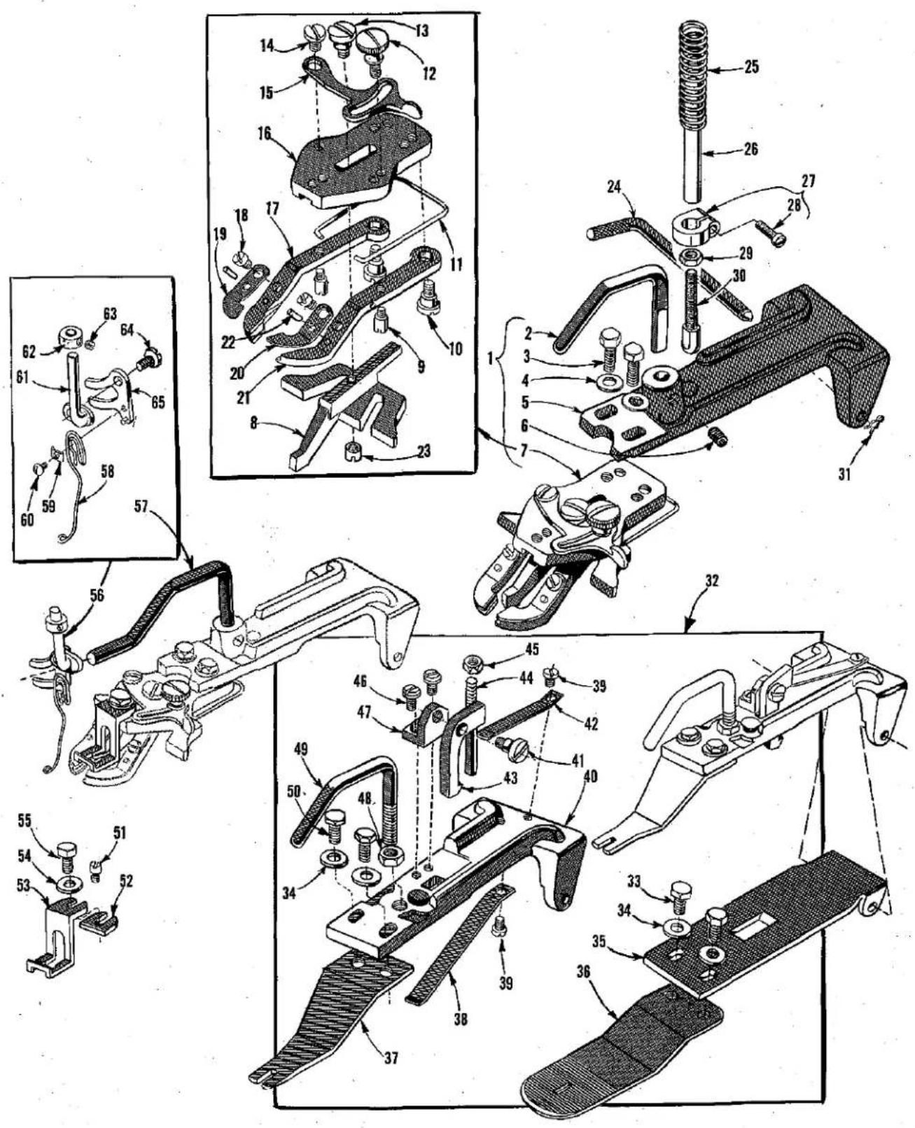
Technical diagram of mechanical assembly with numbered parts and exploded views, likely for assembly or manufacturing purposes.STANDARD BUTTON AND TACKING CLAMPS
| Ref.No. | PartNo. | Description | AmtRec |
| 1 | 430-63-6 | Button Clamp, complete with holder, for Styles 200-1, -2, -6, -7, -8, -9, -25, -26 | 1 |
| 2 | 71-112 | Button Clamp Lifting Rod, also for Styles 200-15, -21, -22, -23, -24, -27 | 1 |
| 3 | 18-873 | Screw, also for Styles 200-10, -15 | 2 |
| 4 | 40-38 | Washer, also for Styles 200-10, -15 | 2 |
| 5 | 99-270 | Button Clamp Holder, also for Styles 200-10, -15, -21, -22 | 1 |
| 99-344 | Button Clamp Holder, for Styles 200-23, -24 | 1 | |
| 6 | 18-1087 | Set Screw, also for Styles 200-10, -15, -21, -22, -23, -24 | 1 |
| 7 | *430-63 | Button Clamp, for 14 to 45 ligne flat buttons, also for Styles 200-10, -15 | 1 |
| 8 | **158-11 | Slide | 1 |
| 9 | 18-930 | Bearing Screw | 2 |
| 10 | 18-929 | Hinge Screw | 2 |
| 11 | 21-315 | Spring | 1 |
| 12 | 18-945 | Clamp Screw | 1 |
| 13 | 18-931 | Screw | 1 |
| 14 | 18-75 | Hinge Screw | 1 |
| 15 | 45-332 | Stop Lever | 1 |
| 16 | 99-316 | Button Clamp Lever Jaw Holder | 1 |
| 17 | 45-347 | Button Clamp Lever Jaw, left | 1 |
| 18 | 1189 L | Screw | 2 |
| 19 | #21-337 | Button Holding Spring, left, for buttons up to 1/8 inch thick | 1 |
| 20 | #21-336 | Button Holding Spring, right, for buttons up to 1/8 inch thick | 1 |
| 21 | 45-346 | Button Clamp Lever Jaw, right | 1 |
| 22 | 22-205 | Locating Pin | 2 |
| 23 | 20-123 | Nut | 1 |
| 24 | 22-224 | Hinge Pin | 1 |
| 25 | 21-317 | Spring | 1 |
| 26 | 22-347 | Stop Pin | 1 |
| 27 | 439-153 | Collar | 1 |
| 28 | 18-375 | Screw | 1 |
| 29 | 12538 | Nut | 1 |
| 30 | 18-1128 | Screw | 1 |
| 31 | 21-407 | Spring Clip | 1 |
| 32 | 430-88 | Tacking Clamp, complete with holder, for Styles 200-16, -17 | 1 |
| 33 | 18-970 | Screw | 2 |
| 34 | 40-38 | Washer | 4 |
| 35 | 99-326 | Holder, lower | 1 |
| 36 | 30-89 | Clamp, lower | 1 |
| 37 | 30-88 | Clamp, upper | 1 |
| 38 | 21-399 | Spring, lower | 1 |
| 39 | 18-623 | Screw | 2 |
| 40 | 99-328 | Holder, upper | 1 |
| 41 | 18-963 | Screw | 1 |
| 42 | 21-398 | Spring, upper | 1 |
| 43 | 166-10 | Pawl | 1 |
| 44 | 22-289 | Stop Pin | 1 |
| 45 | 1160 L | Nut | 1 |
| 46 | 18-596 | Screw | 2 |
| 47 | 50-247 | Bracket | 1 |
| 48 | 20-45 | Nut | 1 |
| 49 | 71-97 | Rod | 1 |
| 50 | 18-677 | Screw | 2 |
| 51 | 18-1010 | Stop Screw, for Style 200-10 | 1 |
| 52 | 157-8 | Thread Pulling Separator Spacer, for Style 200-10 | 1 |
| 53 | 182-16 | Thread Pulling Separator, for Style 200-10 | 1 |
| 54 | 40-38 | Washer, for Style 200-10 | 1 |
| 55 | 18-970 | Screw, for Style 200-10 | 1 |
| 56 | 445-432 | Thread Wiper Lever Assembly, for Style 200-10 | 1 |
| 57 | 71-114 | Rod | 1 |
| 58 | 21-411 | Thread Wiper Spring | 1 |
| 59 | 52958 H | Spring Clamp | 1 |
| 60 | 18-1036 | Screw | 1 |
| 61 | 68-29 | Staff | 1 |
| 62 | 39-C255 | Collar | 1 |
| 63 | 18-C186 | Set Screw | 1 |
| 64 | 1776 L | Screw | 1 |
*NOTE: For 30 to 60 ligne flat buttons, order 430-63-1.
**NOTE: For 30 to 60 ligne flat buttons, order 158-15.
NOTE: For sewing thick buttons requiring up to an additional 11/64 inch in height, order No. 21-393 Button Holding Spring, left and No. 21-392 Button Holding Spring, right, as an extra send and charge item.
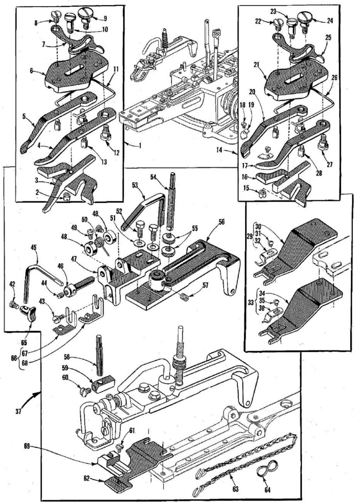
text_image
Technical diagram of automotive bracket assembly with numbered parts and exploded views*EXTRA ATTACHMENTS AVAILABLE FOR CLASS 200
| Ref.No. | PartNo. | Description | Amt.Req. |
| 1 | 430-77 | Snap Fastener Clamp, complete, for Styles 200-1,-2,-6,-7,-8-9,-10,-15---- | 1 |
| 2 | 20-123 | Nut---- | 1 |
| 3 | 158-21 | Slide---- | 1 |
| 4 | 45-472 | Jaw Lever, right---- | 1 |
| 5 | 45-471 | Jaw Lever, left---- | 1 |
| 6 | 99-316-1 | Lever Holder---- | 1 |
| 7 | 45-332 | Stop Lever---- | 1 |
| 8 | 18-75 | Hinge Screw---- | 1 |
| 9 | 18-945 | Clamp Screw---- | 1 |
| 10 | 18-931 | Screw---- | 1 |
| 11 | 21-315 | Spring---- | 1 |
| 12 | 18-929 | Hinge Screw---- | 2 |
| 13 | 18-930 | Bearing Screw---- | 2 |
| 14 | 430-86 | Hook and Eye Clamp, complete, for Styles 200-1,-2,-6,-7,-8,-9,-10,-15---- | 1 |
| 15 | 20-123 | Nut---- | 1 |
| 16 | 158-25 | Slide---- | 1 |
| 17 | 45-459 | Lever, right---- | 1 |
| 18 | 18-125 | Screw---- | 2 |
| 19 | 110-404 | Lever Plate---- | 2 |
| 20 | 45-458 | Lever, left---- | 1 |
| 21 | 99-316-1 | Lever Holder---- | 1 |
| 22 | 18-75 | Hinge Screw---- | 1 |
| 23 | 18-931 | Screw---- | 1 |
| 24 | 18-945 | Clamp Screw---- | 1 |
| 25 | 45-332 | Stop Lever---- | 1 |
| 26 | 21-315 | Spring---- | 1 |
| 27 | 18-929 | Hinge Screw---- | 2 |
| 28 | 18-930 | Bearing Screw---- | 2 |
| 29 | 430-75-1 | Tacking Clamp, complete, for Styles 200-6,-7,-8,-9---- | 1 |
| 30 | 30-75 | Clamp---- | 1 |
| 31 | 18-318 | Screw---- | 1 |
| 32 | 122-46 | Thread Breaking Finger---- | 1 |
| 33 | 430-75 | Tacking Clamp, complete, for Styles 200-1,-2,-10,-15---- | 1 |
| 34 | 30-75 | Clamp---- | 1 |
| 35 | 18-318 | Screw---- | 1 |
| 36 | 122-45 | Thread Breaking Finger---- | 1 |
| 37 | *** 430-57-12 | Shank Button Clamp, complete, with foot treadle, with chain, "S" hooks, but without clamp, adaptor, or work support block, for Styles 200-1,-2,-6,-7,-10,-15 (foot treadle No. 4135-9 not shown)---- | 1 |
| 42 | 18-733 | Screw---- | 1 |
| 43 | CS327 | Screw---- | 1 |
| 44 | SB15 | Screw---- | 1 |
| 45 | 45-372 | Lever---- | 1 |
| 46 | 14-455 | Lever Holding Shaft---- | 1 |
| 47 | 50-238 | Bracket---- | 1 |
| 48 | 39-95 | Collar---- | 2 |
| 49 | 18-623 | Screw---- | 2 |
| 50 | 21-353 | Spring---- | 1 |
| 51 | 40-38 | Washer---- | 2 |
| 52 | 18-873 | Screw---- | 2 |
| 53 | 71-112 | Rod---- | 1 |
| 54 | 18-965 | Screw---- | 1 |
| 55 | 20-60 | Knurled Nut---- | 2 |
| 56 | 99-308 | Button Clamp Holder---- | 1 |
| 57 | 18-1087 | Set Screw---- | 1 |
| 58 | 17-155 | Stud---- | 1 |
| 59 | 115-127 | Block---- | 1 |
| 60 | 18-750 | Screw---- | 1 |
| 61 | 18-307 | Screw---- | 1 |
| 62 | 24-281 | Feed Plate---- | 1 |
| 63 | 130-9 | Chain---- | 1 |
| 64 | 131-C163-1 | "S" Hook---- | 1 |
| 65 | ** 430-55 | Shank Button Holding Clamp for Styles 200-1,-2,-6,-7,-15---- | 1 |
| 66 | ** 490-49 | Shank Button Adapter, adjustable, for Styles 200-1,-2,-6,-7,-15---- | 1 |
| 67 | 8-132 | Guard, adjustable---- | 1 |
| 68 | 90-49 | Adapter---- | 1 |
| 69 | ** 115-151 | Shank Button Work Support Block for Styles 200-1,-2,-6,-7,-15---- | 1 |
* Machines on which attachments can be used are indicated in parts descriptions.
** Due to the many varieties of shank buttons, this combination of holding clamp, adapter, and work support block is illustrated only to show their positions in the machine. In order to secure the proper combination of parts, a sample button must be submitted.
*** When used for buttons greater than 45 ligne, also order needle plate No. 110-204 as an extra send and charge item.

text_image
Technical diagram of mechanical assembly with numbered parts and exploded views, likely from an engineering manual.STANDARD ACCESSORIES FURNISHED WITH MACHINES IN CLASS 200 *EXTRA ATTACEMENTS AVAILABLE
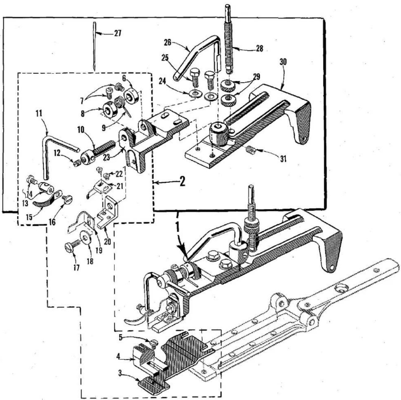
| Ref. No. | Part No. | Description | Ant Rec |
| 1 | 407-10 | Button Spacing Gauge, complete, left side, for Styles 200-1, -2, -6, -7, -8, -9, -10, -15, -23, -24 | 1 |
| 2 | 18-974 | Screw | 1 |
| 3 | 7-10 | Gauge | 1 |
| 4 | 407-11 | Button Spacing Gauge, complete, right side, for Styles 200-1, -2, -6, -7, -8, -9, -10, -15, -23, -24 | 1 |
| 5 | 18-974 | Screw | 1 |
| 6 | 7-11 | Gauge | 1 |
| 7 | 24-304 | Feed Plate, for sewing sideways on two hole buttons, for Styles 200-1, -2, -6, -7, -10, -15, -23, -24 | 1 |
| 8 | 99-313-18 | Holder, for 18 ligne stay buttons, for Styles 200-1, -2, -6, -7, -8, -9, -10, -15 | 1 |
| 99-313-17 | Holder, for 17 ligne stay buttons | 1 | |
| 99-313-19 | Holder, for 19 ligne stay buttons | 1 | |
| 99-313-20 | Holder, for 20 ligne stay buttons | 1 | |
| 99-313-22 | Holder, for 22 ligne stay buttons | 1 | |
| 99-313-23 | Holder, for 23 ligne stay buttons | 1 | |
| 99-313-24 | Holder, for 24 ligne stay buttons | 1 | |
| 9 | 18-987 | Screw | 1 |
| 10 | 18-986 | Clamping Screw | 1 |
| 11 | 5-525-11/32 | Shanking Foot, for sewing 11/32 inch from garment, for Styles 200-1, -2, -6, -7, -8, -9, -10, -15 | 1 |
| 5-525-1/8 | Shanking Foot, for sewing 1/8 inch from garment | 1 | |
| 12 | 424-299 | Button Necking Attachment, complete with feed plate, for Styles 200-1, -2, -6, -7, -10, -15 | 1 |
| 13 | 18-974 | Screw | 1 |
| 14 | 182-15 | Separator | 1 |
| 15 | 475-231 | Guide | 1 |
| 16 | 24-299 | Feed Plate | 1 |
| 17 | 408-147 | Sewing Guard (complete) | 1 |
| 18 | 8-147 | Plastic Guard | 1 |
| 19 | 22768 B | Screw | 2 |
| 20 | 41358 | Washer | 2 |
| 21 | 45-498 | Lever | 1 |
| 22 | 22894 P | Screw | 1 |
| 23 | 21-449 | Spring | 1 |
| 24 | 12934 A | Nut | 1 |
| 25 | 115-171 | Mounting Block, marked "A" | 1 |
| 26 | 40-101 | Washer, spring | 1 |
| 27 | 22757 | Screw | 1 |
| 28 | 18-750 | Screw, mounting | 1 |
| 29 | 4135-9 | Foot Treadle, complete | 1 |
| 30 | 135-9 | Foot Treadle, main section | 1 |
| 31 | 45-424 | Lever | 1 |
| 32 | 40-181 | Washer | 1 |
| 33 | 18-1033 | Screw | 1 |
| 34 | 1504 L | Wood Screw | 2 |
| 35 | 43-27 | Rivet | 1 |
| 36 | 50-265 | Bracket | 1 |
| 37 | 21-408 | Spring | 1 |
| 38 | 421 D-34 | Chain | 1 |
| 39 | 660-264 | "S" Hook | 2 |
| 40 | 131-C163-1 | "S" Hook | 1 |
| 41 | 652-16 | Washer | 4 |
| 42 | 59-6 | Double End Wrench, 5/16 and 7/16 hex. | 1 |
| 43 | WR56 | Allen Wrench, for 1/8 inch hex. | 1 |
| 44 | WR57 | Allen Wrench, for 5/32 inch hex. | 1 |
| 45 | 650-14 | Stove Bolt | 4 |
| 46 | 28604 P | Grease Tube | 1 |
| 47 | 21201 | Screwdriver, 1/4 inch blade, 7 inch over all | 1 |
| 48 | 413 D | Oil Can | 1 |
| 49 | 403-11 | Thread Stand | 1 |
| 50 | SC299 | Wood Screw | 2 |
*OTHER ATTACHMENTS AVAILABLE, NOT ILLUSTRATED
| 701-1 | "Speed Feed" Shank Button Eopper, for 14 thru 30 ligne shank buttons, standard equipment on Styles200-21,-22; can be used on Styles 200-6,-7,-8,-9 | ||||||
| 2800 D-2C-14 | "So-Thru" Button Hopper, for flat or concave, 14 to 16 ligne buttons, for Styles 200-1,-2,-23,-24 | ||||||
| 2800 D-2C-17 | "So-Thru" Button Hopper, for 17 to 19 ligne buttons | ||||||
| 2800 D-2C-20 | "So-Thru" Button Hopper, for 20 to 23 ligne buttons | ||||||
| 2800 D-2C-24 | "So-Thru" Button Hopper, for 24 to 27 ligne buttons | ||||||
| 2800 D-2C-28 | "So-Thru" Button Hopper, for 28 to 30 ligne buttons | ||||||
| 2800 D-2D-14 | "So-Thru" Button Hopper, for dome shaped, 14 to 16 ligne buttons, for Styles 200-1,-2,-23,-24 | ||||||
| 2800 D-2D-17 | "So-Thru" Button Hopper, for 17 to 19 ligne buttons | ||||||
| 2800 D-2D-20 | "So-Thru" Button Hopper, for 20 to 23 ligne buttons | ||||||
| 2800 D-2D-24 | "So-Thru" Button Hopper, for 24 to 27 ligne buttons | ||||||
| 2800 D-2D-28 | "So-Thru" Button Hopper, for 28 to 30 ligne buttons | ||||||
* Machines on which attachments can be used are indicated in parts description.
text_image
Technical diagram of a mechanical assembly with numbered parts, likely for repair or assembly instructions.STANDARD SHANK BUTTON HOLDER FOR STYLE 200-27
| Ref.No. | PartNo. | Description | Amt.Req. |
| 1 | 430-90-1 | Shank Button Holder Assembly, complete,for Style 200-27----1 | |
| 2 | 430-90 | Shank Button Holder----1 | |
| 3 | 24-281 | Feed Plate----1 | |
| 4 | 115-125 | Work Support Block, .305 inch high,for 10 to 40 ligne buttons----1 | |
| *115-128 | Work Support Block, .180 inch high,for 10 to 30 ligne buttons----1 | ||
| *115-133 | Work Support Block, .490 inch high,for 40 to 50 ligne buttons----1 | ||
| 5 | 18-307 | Screw, for work support block----1 | |
| 6 | 39-95 | Collar, for lever holding shaft----1 | |
| 7 | 18-623 | Screw, for collar----2 | |
| 8 | 39-95 | Collar, for lever holding shaft----1 | |
| 9 | 21-353 | Spring, for lever holding shaft----1 | |
| 10 | 14-455 | Lever Holding Shaft----1 | |
| 11 | 45-468 | Lever----1 | |
| 12 | SB15 | Screw, for lever----1 | |
| 13 | 30-90 | Clamp, for shank button holder----1 | |
| 14 | 18-733 | Screw----1 | |
| 15 | 99-351 | Shank Button Holder----1 | |
| 16 | 18-974 | Screw, for shank button holder----1 | |
| 17 | 75 C | Screw, for clamp bracket and clampblade, upper----1 | |
| 18 | 51225 W | Washer, for clamp bracket andclamp blade, upper----1 | |
| 19 | 162-21 | Clamp Blade, upper----1 | |
| 20 | 50-296 | Shank Button Clamp Bracket, left----1 | |
| 21 | 162-20 | Clamp Blade, lower----1 | |
| 22 | 73 A | Screw, for clamp blade, lower----2 | |
| 23 | 50-238 | Bracket, for clamp----1 | |
| 24 | 40-38 | Washer, for bracket----2 | |
| 25 | 18-873 | Screw, for bracket----2 | |
| 26 | 71-112 | Button Holder Lifting Rod----1 | |
| 27 | 29 LES-110/044 | Needle, for use with 115-125 worksupport block----4 | |
| *29 ELS-110/044 | Needle, for use with 115-133 worksupport block----1 | ||
| *29 LSS-110/044 | Needle, for use with 115-128 worksupport block----1 | ||
| †28 | 18-965 | Screw----1 | |
| †29 | 20-60 | Knurled Nut----2 | |
| 30 | 99-308 | Button Clamp Holder----1 | |
| 31 | 18-1087 | Set Screw, for button holder lifting rod----1 |
* Available as extra send and charge item.
† Not a component of 430-90-1.
text_image
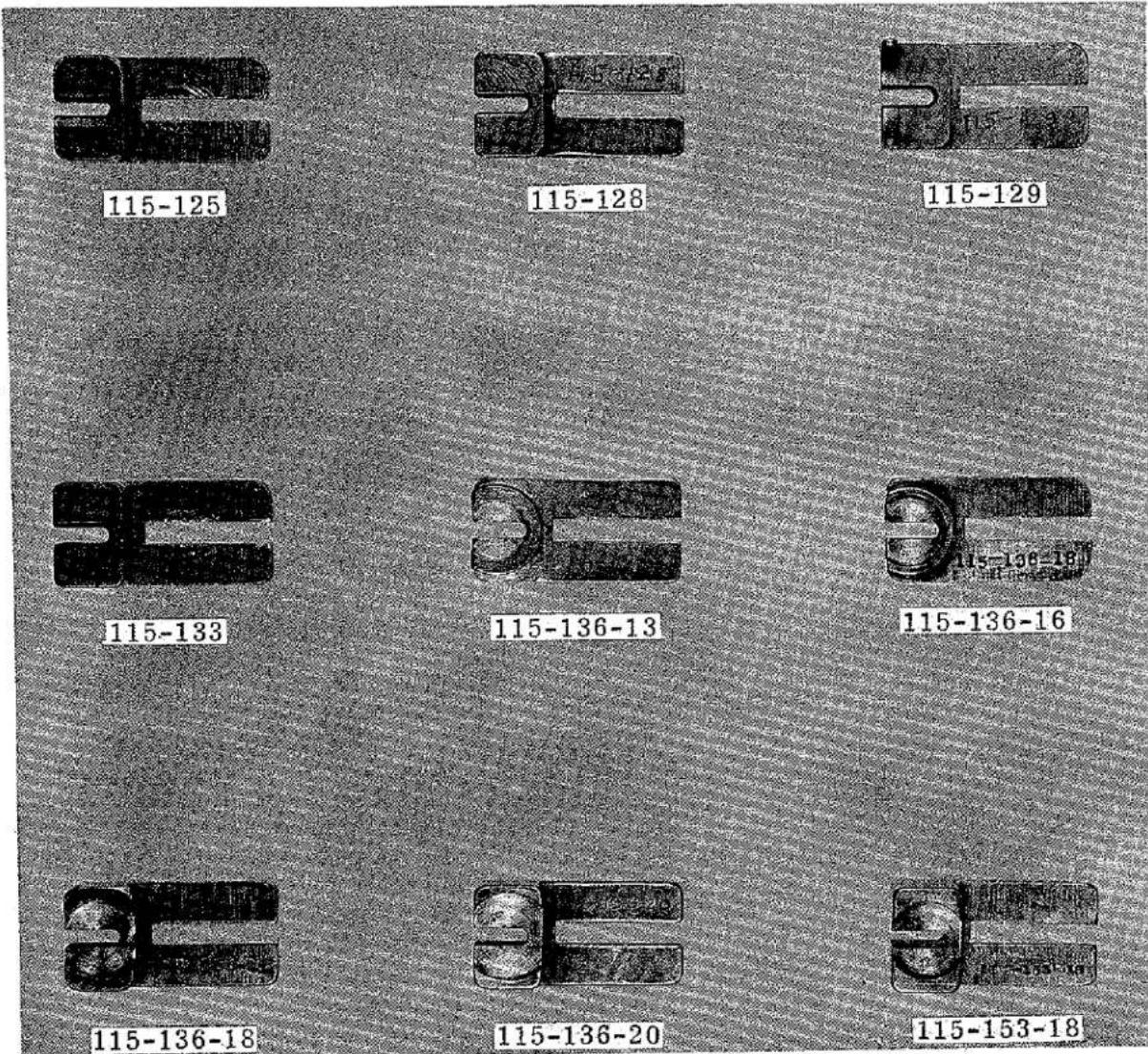
115-125 115-128 115-129 115-133 115-136-13 115-136-16 115-136-18 115-136-20 115-153-18WORK SUPPORTING BLOCKS
| Part No. | Description |
| 115-125 | Work Supporting Block, for 10 to 45 ligne buttons, for flat work |
| 115-128 | Work Supporting Block, for 10 to 30 ligne buttons, for flat work |
| 115-129 | Work Supporting Block, for 10 to 30 ligne buttons, for blind stitch |
| 115-133 | Work Supporting Block, for up to 50 ligne buttons |
| 115-136-13 | Work Supporting Block, for 13 ligne stay buttons |
| 115-136-16 | Work Supporting Block, for 16 ligne stay buttons |
| 115-136-18 | Work Supporting Block, for 18 ligne stay buttons |
| 115-136-20 | Work Supporting Block, for 20 ligne stay buttons |
| 115-153-18 | Work Supporting Block, for 18 ligne stay buttons |
text_image
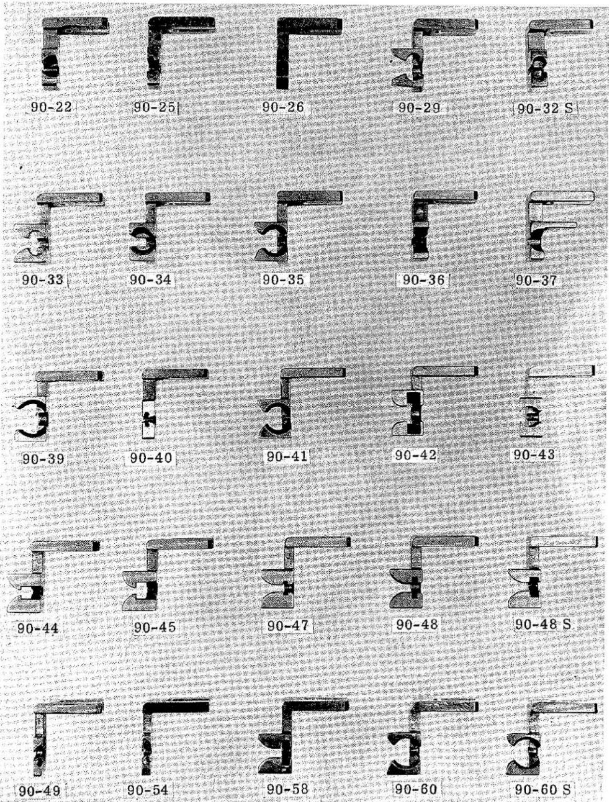
90-22 90-25 90-26 90-29 90-32 S 90-33 90-34 90-35 90-36 90-37 90-39 90-40 90-41 90-42 90-43 90-44 90-45 90-47 90-48 90-48 S 90-49 90-54 90-58 90-60 90-60 SADAPTERS AND ASSEMBLED CLAMPS, FOR SHANK TYPE BUTTONS
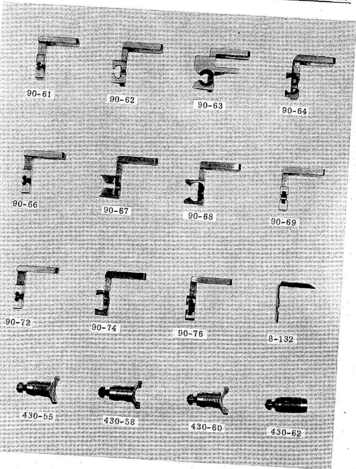
text_image
90-61 90-62 90-63 90-64 90-66 90-67 90-68 90-69 90-72 90-74 90-76 8-132 430-55 430-58 430-60 430-62NUMERICAL INDEX OF PARTS
| Part No. | Page No. | Part No. | Page No. | Part No. | Page No. | Part No. | Page No. |
| 5-525-1/8 | 37 | 18-818 | 29 | 21-336 | 33 | 34-69 | 23 |
| 5-525-11/32 | 37 | 18-819 | 27 | 21-337 | 33 | 34-71 | 23 |
| 7-10 | 37 | 18-826 | 27 | 21-343 | 31 | 34-73 | 23 |
| 7-11 | 37 | 18-827 | 27 | 21-353 | 35, 39 | 34-75 | 23 |
| 8-111 | 31 | 18-835 | 25 | 21-360 | 27 | 34-81 | 23 |
| 8-132 | 35 | 18-854 | 31 | 21-366 | 27 | 34-82 | 23 |
| 8-147 | 37 | 18-873 | 33, 35, 39 | 21-379 | 27 | 34-91 | 23 |
| 14-362 | 21 | 18-878 | 21 | 21-381 | 31 | 34-95 | 23 |
| 14-363 | 21 | 18-907 | 21 | 21-398 | 33 | 34-96 | 23 |
| 14-364 | 23 | 18-920 | 31 | 21-399 | 33 | 34-104 | 25 |
| 14-365 | 27 | 18-925 | 21 | 21-407 | 33 | 35-15 | 29 |
| 14-366 | 23 | 18-929 | 33, 35 | 21-408 | 37 | 35-16 | 27 |
| 14-368 | 27 | 18-930 | 33, 35 | 21-411 | 33 | 35-17 | 27 |
| 14-399 | 19 | 18-931 | 33, 35 | 21-414 | 31 | 35-20 | 23 |
| 14-455 | 35, 39 | 18-934 | 23, 31 | 21-449 | 37 | 36-21 | 23 |
| 14-488 | 27 | 18-945 | 33, 35 | 21-457 | 27 | 39-95 | 35, 39 |
| SB15 | 35, 39 | 18-949 | 23 | 22-175 | 31 | 39-107 | 23 |
| 16-288 | 19 | 18-958 | 21 | 22-195 | 31 | 39-131 | 23 |
| 16-289 | 19 | 18-959 | 21 | 22-205 | 33 | 39-143 | 23 |
| 16-291 | 19 | 18-963 | 33 | 22-206 | 31 | 39-151 | 25 |
| 16-292 | 19 | 18-965 | 35, 39 | 22-C214-13 | 29 | 39-C255 | 33 |
| 16-297 | 19 | 18-966 | 29 | 22-219 | 29 | 40-38 | 25, 29, 33, |
| 16-334 | 19 | 18-967 | 21 | 22-221 | 31 | 35, 39 | |
| 16-398 | 19 | 18-968 | 21 | 22-224 | 33 | 40-63 | 21 |
| 16-411 | 19 | 18-970 | 33 | 22-235 | 27 | 40-101 | 37 |
| 16-412 | 19 | 18-974 | 37, 39 | 22-238 | 31 | 40-135 | 21, 23 |
| 17-124 | 29 | 18-982 | 21 | 22-251 | 31 | 40-143 | 27 |
| 17-155 | 35 | 18-984 | 23 | 22-255 | 19 | 40-168 | 27 |
| 18-39 | 21, 25 | 18-986 | 37 | 22-266 | 27 | 40-169 | 21 |
| 18-71 | 21 | 18-987 | 37 | 22-289 | 33 | 40-170 | 31 |
| 18-75 | 33, 35 | 18-996 | 21, 23, 25 | 22-347 | 33 | 40-181 | 37 |
| 18-125 | 35 | 18-997 | 31 | 24-281 | 29, 35, 39 | 40-188 | 31 |
| 18-C186 | 33 | 18-1010 | 33 | 24-299 | 37 | 40-198 | 27 |
| 18-272 | 21 | 18-1022 | 29 | 24-304 | 37 | 41-41 | 31 |
| 18-280 | 27 | 18-1023 | 29 | 24-338 | 29 | 41-47 | 21 |
| 18-286 | 31 | 18-1033 | 37 | 25-11 | 21 | 41-49 | 31 |
| 18-307 | 35, 39 | 18-1035 | 19 | 26-147 | 31 | 41-53 | 31 |
| 18-318 | 35 | 18-1036 | 33 | 26-163 A | 27 | 42-34 | 27 |
| 18-330 | 25, 29 | 18-1047 | 31 | 27-155 | 23 | 43-27 | 37 |
| 18-375 | 33 | 18-1076 | 31 | 27-168 | 23 | 44-288 | 21 |
| 18-391 | 21 | 18-1077 | 31 | 27-169 | 21 | 44-334 | 21 |
| 18-392 | 27, 29 | 18-1087 | 33, 35, 39 | 27-170 | 21 | 45-288 | 29 |
| 18-547 | 31 | 18-1088 | 27, 31 | 27-171 | 21 | 45-290 | 29 |
| 18-562 | 27 | 18-1112 | 25 | 27-189 | 23 | 45-327 | 27 |
| 18-596 | 33 | 18-1128 | 33 | 27-190 | 23 | 45-331 | 25 |
| 18-619 | 25, 27, 29 | 20-34 | 25, 27 | 27-191 | 23 | 45-332 | 33, 35 |
| 18-623 | 33, 35, 39 | 20-45 | 33 | 27-225 | 23 | 45-333 | 19 |
| 18-626 | 29 | 20-60 | 31, 35, 39 | 27-226 | 23 | 45-335 A | 21 |
| 18-629 | 25 | 20-80 | 21 | 29 KLS-110/044 | 39 | 45-346 | 33 |
| 18-634 | 23 | 20-81 | 21 | 29 LRS-110/044 | 39 | 45-347 | 33 |
| 18-677 | 33 | 20-98 | 31 | 29 LSS-110/044 | 39 | 45-348 | 27 |
| 18-725 | 21 | 20-109 | 29 | 30-75 | 35 | 45-372 | 35 |
| 18-730 | 21, 23, 25 | 20-123 | 33, 35 | 30-88 | 33 | 45-404 | 27 |
| 18-732 | 27 | 20-127 | 21 | 30-89 | 33 | 45-416 | 29 |
| 18-733 | 35, 39 | 20-128 | 27 | 30-90 | 39 | 45-424 | 37 |
| 18-738 | 19 | 21-96 | 19, 27 | 32-191 | 19 | 45-426 | 19 |
| 18-745 | 27 | 21-229 | 21 | 32-192 | 19 | 45-432 | 33 |
| 18-747 | 25, 27 | 21-284 | 31 | 32-198 | 31 | 45-434 | 31 |
| 18-750 | 31, 35, 37 | 21-287 | 29 | 32-209 | 31 | 45-438 | 35 |
| 18-752 | 31 | 21-295 | 19 | 32-303 | 31 | 45-459 | 35 |
| 18-766 | 29 | 21-300 | 29 | 34-35 | 23 | 45-488 | 39 |
| 18-786 | 31 | 21-310 | 31 | 34-47 | 23 | 45-471 | 35 |
| 18-800 | 21 | 21-315 | 33, 35 | 34-53 | 23 | 45-472 | 35 |
| 18-809 | 27 | 21-317 | 33 | 34-54 | 23 | 45-490 | 27 |
| 18-814 | 29 | 21-321 | 19 | 34-65 | 25 | 45-498 | 37 |
| 18-816 | 31 | 21-322 | 25 | 34-68 | 23 | 45-503 | 27 |
NUMERICAL INDEX OF PARTS
| Part No. | Page No. | Part No. | Page No. | Part No. | Page No. | Part No. | Page No. |
| 46-135 | 27 | 99-344 | 33 | 190-3 L | 23 | 1029 L | 23 |
| 46-137 | 29 | 99-345 | 31 | CS231 | 31 | 1036 L | 29 |
| 46-138 | 29 | 99-351 | 39 | SC299 | 37 | 1158 L | 19,27 |
| 46-162 | 27 | 110-205 | 29 | CS303-1/2 | 27 | 1160 L | 19,25,29,31,33 |
| 46-168 | 25 | 110-206 | 29 | CS327 | 35 | ||
| 46-169 | 25 | 110-213 | 31 | CS337 | 19,25,29 | 1170 L | 25 |
| 46-173 | 29 | 110-302 | 31 | 403-11 | 37 | 1183 L | 31 |
| 46-174 | 29 | 110-304 | 31 | 407-10 | 37 | 1185 L | 27 |
| 46-175 | 27 | 110-318 | 29 | 407-11 | 37 | 1189 L | 33 |
| 46-181 | 19 | 110-328 | 29 | 408-147 | 37 | 1206 L | 27 |
| 46-182 | 19 | 110-333 | 31 | 413 D | 37 | 1220 L | 19 |
| 46-183 | 19 | 110-334 | 31 | 421 D-34 | 37 | 1221 L | 31 |
| 49-25 | 23 | 110-404 | 35 | 424-299 | 37 | 1235 L | 19 |
| 49-33 | 23 | 115-106 | 27 | 430-55 | 35 | 1311 L | 25 |
| 50-215 | 19 | 115-107 | 31 | 430-57-12 | 35 | 1316 L | 31 |
| 50-238 | 35, 39 | 115-108 | 29 | 430-63 | 33 | 1333 L | 21 |
| 50-247 | 33 | 115-125 | 39,41 | 430-63-6 | 33 | 1504 L | 37 |
| 50-265 | 37 | 115-127 | 35 | 430-75 | 35 | 1776 L | 33 |
| 50-295 | 31 | 115-128 | 39,41 | 430-75-1 | 35 | 2339 E | 21 |
| 50-296 | 39 | 115-129 | 41 | 430-77 | 35 | 2800 D-2C-14 | 37 |
| 51-20 | 21 | 115-133 | 39,41 | 430-86 | 35 | 2800 D-2C-17 | 37 |
| 51-22 | 25 | 115-136-13 | 41 | 430-88 | 33 | 2800 D-2C-20 | 37 |
| WR56 | 37 | 115-136-16 | 41 | 430-90 | 39 | 2800 D-2C-24 | 37 |
| 57-23 | 21 | 115-136-18 | 41 | 430-90-1 | 39 | 2800 D-2C-28 | 37 |
| 57 WB | 31 | 115-136-20 | 41 | 432-263 | 31 | 2800 D-2D-14 | 37 |
| WR57 | 37 | 115-137 | 29 | 432-303 | 31 | 2800 D-2D-17 | 37 |
| 58-39 | 21 | 115-151 | 35 | 432-305 | 19 | 2800 D-2D-20 | 37 |
| 59-6 | 37 | 115-153-18 | 41 | 432-306 | 19 | 2800 D-2D-24 | 37 |
| 61-32 | 31 | 115-171 | 37 | 433-139 | 21 | 2800 D-2D-28 | 37 |
| 61-33 | 31 | 115-175 | 27 | 434-40 | 23 | 4110-317 | 29 |
| 61-80 | 23 | 117-39 | 21 | 434-101 | 25 | 4110-329 | 29 |
| 63-32 | 21 | 117-40 | 21 | 434-102 | 25 | 4115-104 | 27 |
| 68-21 | 31 | 122-45 | 35 | 439-153 | 33 | 4119-86 | 19 |
| 68-22 | 31 | 122-46 | 35 | 444-334 | 21 | 4124-49 | 21 |
| 68-29 | 33 | 122-58 | 23 | 445-286 | 27 | 4124-50 | 21 |
| 69-16 | 29 | 130-9 | 35 | 445-298 | 21 | 4135-9 | 37 |
| 69-17 | 29 | 131-C163-1 | 35,37 | 445-349 | 23 | 4186-16 | 19 |
| 70-50 | 23 | 131-C163-2 | 19 | 445-370 | 27 | 4187-3 | 27 |
| 71-74 | 21 | 135-9 | 37 | 445-405 | 27 | 12538 | 33 |
| 71-92 | 27 | 137-19 | 21 | 445-432 | 33 | 12934 A | 37 |
| 71-97 | 33 | 138-15 | 27 | 446-136 | 29 | 12957 E | 19 |
| 71-112 | 33, 35, 39 | 141-4 | 19 | 446-173 | 29 | 21201 | 37 |
| 71-114 | 33 | 142-6 | 25 | 447-105 | 21 | 21657 E | 31 |
| 71-124 | 27 | 144-25 | 19 | 458-39 | 21 | 22548 | 31 |
| 73 A. | 39 | 144-31 | 31 | CS462 | 21 | 22585 A. | 25 |
| 75 C. | 39 | 155-14 | 29 | 468-21 | 31 | 22651 ED-6 | 27 |
| 75-267 | 19 | 157-8 | 33 | 468-22 | 31 | 22652 E-20 | 31 |
| 79-31 | 29 | 157-13 | 27 | 475-231 | 37 | 22653 B-10 | 27 |
| 79-37 | 21 | 158-11 | 33 | 478-10 | 21 | 22653 E-14 | 27 |
| SB79 | 31 | 158-17 | 29 | 478-27 | 21,23 | 22757 | 37 |
| 89-65 | 25 | 158-19 | 29 | 490-49 | 35 | 22768 B. | 37 |
| 90-49 | 35 | 158-21 | 33,35 | 650-14 | 37 | 22894 P. | 37 |
| 98 | 21 | 158-25 | 35 | 652-16 | 27,37 | 28604 P. | 37 |
| 99-270 | 33 | 158-29 | 29 | 652 K-14 | 21 | 41358 | 37 |
| 99-308 | 35, 39 | 162-20 | 39 | 660-264 | 37 | 51225 W. | 39 |
| 99-313-17 | 37 | 162-21 | 39 | 666-19 | 21 | 51758. | 31 |
| 99-313-18 | 37 | 164-39 | 23 | 701-1 | 37 | 52958 H. | 33 |
| 99-313-19 | 37 | 164-40 | 23 | 787 L. | 19 | 60038 K. | 27 |
| 99-313-20 | 37 | 164-41 | 23 | 835 L. | 27 | 61292 H. | 31 |
| 99-313-22 | 37 | 166-7 | 21 | 861 L. | 25 | 61470 D. | 31 |
| 99-313-23 | 37 | 166-10 | 33 | 888 L. | 31 | 62271 C. | 31 |
| 99-313-24 | 37 | 166-11 | 25 | 1003 L. | 19,21 | ||
| 99-316 | 33 | 180-4 | 25 | 1005 L. | 19,21,23 | ||
| 99-316-1 | 35 | 182-15 | 37 | 1009 L. | 19,21 | ||
| 99-326 | 33 | 182-16 | 33 | 1022 L. | 21 | ||
| 99-328 | 33 | 190-2 L. | 21 | 1025 L. | 21 |
Union Special Wants to Help You Cut Sewing Machine Maintenance Costs
Union Special is offering two practical systems to help pinpoint and reduce your sewing machine maintenance costs: a record keeping system to help spot machines requiring abnormally high maintenance, and a parts inventory system to speed routine repairs.
Machine Maintenance Records
Repair-prone machines or inexperienced competent operators can eat up your maintenance dollars in short order. To help spot these problems, Union Special suggests two variations of a simple maintenance record keeping system using cards provided by Union Special.
The first system utilizes a "Machine Maintenance Record" card (Form 237) for each sewing machine in a plant. When a repair is required, the card is pulled from the file and the repair date, parts used, and their cost are entered in the spaces provided and the card is refiled.
text_image
MACHINE MAINTENANCE RECORD MARKER NAME STYLE TYPE REEVE RERSAL NO. DATE PURCH. DATE SYMBOL PART LINED COST DASE KEYMBOL PART LISTED CONI FORM 237-Machine Maintenance Record cardThe second system is normally used when more detailed information on repair costs is desired. Two record cards are used: a "Repair Request Card" (Form 234), and a "Machine Repair Record" (Form 233). When a machine requires service, the forelady or foreman fills out the top of a "Repair Request Card" and gives it to a mechanic. He fills in the time the repair work is started, the parts used and their cost,
and the completion time. This data is then transferred to the permanent "Machine Repair Record" kept in the office.
Whichever system is used, management now has an invaluable tool to reduce needless maintenance costs.
Repair Part Inventories
While record keeping tells management which machines require abnormally high maintenance, it does little to help reduce the downtime caused by routine repairs. To alleviate this situation, Union Special recommends that manufacturers establish a formal parts inventory system for each type of sewing machine they operate.
Excessive machine downtime and wasted hours by mechanics can be eliminated with an orderly in-plant inventory of the most commonly needed parts. There is no longer a need to cannibalize other machines for spare parts. Long waits for deliveries are avoided and machine downtime is kept to a minimum. The cost of a parts inventory is small when the overall savings are considered.
text_image
MACHINE REPAIR RECORD CARD MARKETS NAME USEERS SYMBOL REPAIR REQUEST CARD CLOVE IMPORTARY ORDER MACHINE NAME: ORDER: MANUAL NO. ORDER BY: NO. CREATURE NO. PARTS USED ITEM PART NUMBER COST FORM 233- Machine Repair Record card FORM 234- Repair Request Card THE STARTED TIME COMPLETED REGRANES NO. NO. 100% 100% 100% 100% 100% 100% 100% 100% 100% 100% 100% 100% 100% 100% 100% 100% 100% 100% DATE MARGIN NO. LANDING COST PARTS COST TOTAL COST BASIS PARTS USED ITEM PART NUMBER COST FORM 233- Machine Repair Record card FORM 234- Repair Request Card THE STARTED TIME COMPLETED REGRANES NO. NO. 100% 100% 100% 100% 100% 100% 100% 100% 100% 100% 100% ITEM PART NUMBER COST FORM 233- Machine Repair Record card FORM 234- Repair Request Card THE STARTED TIME COMPLETED REGRANES NO. NO. 100% 100% 100% 100% 100% 100% 100% 100% 100% 100% 100% 10For free sample copies of the machine record cards and spare part inventory lists for a variety of the most popular machines, contact your local Union Special Representative or write direct to Union Special.
U Union Special
Style 200-1
Suggested Minimum Spare Parts List*
| Part Number | Description | Minimum Quantity Per 5 Machines | Part Number | Description | Minimum Quantity Per 5 Machines |
| 21-321 | Spring | 2 | 21-381 | Spring | 1 |
| 18-272 | Screw, needle | 2 | 18-818 | Screw | 1 |
| 44-288 | Pulley clutch disc | 1 | 18-730 | Screw | 2 |
| 21-229 | Spring | 2 | LS-314 | Screw | 2 |
| 36-21 | Looper | 2 | 40-139 | Washer | 2 |
| 18-949 | Looper clamping screw | 2 | 24-244 | Feed plate | 1 |
| 18-1088 | Screw | 1 | 18-873 | Screw | 2 |
| 60038 K | Washer | 1 | 40-188 | Washer | 1 |
| 18-750 | Screw | 1 | 51-20 | Stop motion disc latch | 1 |
| 21-366 | Spring | 2 | 18-997 | Screw | 1 |
| 18-1087 | Set Screw | 2 | 1333 L | Set screw | 1 |
| 21-416 | Stop motion disc spring | 30 | 18-920 | Screw | 4 |
| 45-302 | Lever | 1 | 28604 P | Grease tube | 1 |
| 18-280 | Screw | 1 | 29 S | Needles (Specify size) | 100 |
UnionSpecial®
Style 200-16
Suggested Minimum Spare Parts List*
| Part Number | Description | Minimum Quantity Per 5 Machines | Part Number | Description | Minimum Quantity Per 5 Machines |
| 29 S | Needles (specify size) | 100 | 18-996 | Screw | 2 |
| 21-321 | Spring | 2 | 26-163 | Stop motion plunger | 1 |
| 18-272 | Screw, needle | 4 | 1206 L | Screw | 2 |
| 44-288 | Pulley clutch disc | 1 | 21-381 | Spring | 1 |
| 21-229 | Spring | 2 | 18-818 | Screw | 1 |
| 36-21 | Looper | 2 | 18-730 | Screw | 2 |
| 18-949 | Looper clamping screw | 2 | 18-970 | Screw | 2 |
| 18-1088 | Screw | 1 | 40-38 | Washer | 2 |
| 60038 K | Washer | 1 | 30-89 | Clamp | 1 |
| 18-750 | Screw | 1 | 18-677 | Screw | 2 |
| 21-366 | Spring | 2 | 21-399 | Spring, lower | 1 |
| 18-1087 | Set screw | 2 | 21-398 | Spring, upper | 1 |
| 21-416 | Stop motion disc spring | 30 | 166-10 | Pawl | 1 |
| 45-302 | Lever | 1 | 40-188 | Washer | 1 |
| 18-280 | Screw | 1 | 51-20 | Stop motion disc latch | 1 |
| 18-71 | Screw | 2 | 18-997 | Screw | 1 |
| 18-907 | Screw | 2 | 1333 L | Set screw | 1 |
| 122-29 | Loop positioning finger | 1 | 18-920 | Screw | 4 |
| 18-634 | Screw | 2 | 28604 P | Grease tube | 1 |
| 1005 L | Screw | 2 |
UnionSpecial®
Style 200-26
Suggested Minimum Spare Parts List*
| Part Number | Description | Minimum Quantity Per 5 Machines | Part Number | Description | Minimum Quantity Per 5 Machines |
| 29 S | Needles (specify size) | 100 | 18-634 | Screw | 2 |
| 21-321 | Spring | 2 | 1005 L | Screw | 2 |
| 18-272 | Screw, needle | 4 | 18-996 | Screw | 2 |
| 44-288 | Pulley clutch disc | 1 | 26-163 | Stop motion plunger | 1 |
| 21-229 | Spring | 2 | 1206 L | Screw | 2 |
| 36-21 | Looper | 2 | 21-381 | Spring | 1 |
| 18-949 | Looper clamping screw | 2 | 18-818 | Screw | 1 |
| 18-1088 | Screw | 1 | 18-730 | Screw | 2 |
| 60038 K | Washer | 1 | LS-314 | Screw | 2 |
| 18-750 | Screw | 1 | 40-139 | Washer | 2 |
| 21-366 | Spring | 2 | 24-244 | Feed plate | 1 |
| 18-1087 | Set screw | 2 | 18-873 | Screw | 2 |
| 21-416 | Stop motion disc spring | 30 | 40-188 | Washer | 1 |
| 45-302 | Lever | 1 | 51-20 | Stop motion disc latch | 1 |
| 18-280 | Screw | 1 | 18-997 | Screw | 1 |
| 18-71 | Screw | 2 | 1333 L | Set screw | 1 |
| 18-907 | Screw | 2 | 18-920 | Screw | 4 |
| 122-29 | Loop positioning finger | 1 | 28604 P | Grease tube | 1 |

natural_image
World map with latitude and longitude grid lines, showing continents and oceans (no text labels)WORLDWIDE SALES AND SERVICE
Union Special Corporation maintains sales and service facilities throughout the world. These offices will aid you in the selection of the right sewing equipment for your particular operation. Union Special Corporation representatives and service technicians are factory trained and are able to serve your needs promptly and efficiently. Whatever your location, there is a qualified representative to serve you.
Corporate Office:
One Union Special Plaza
Huntley, IL 60142
Phone: 708·669·5101
Fax: 708·669·1096
European Distribution Center:
Union Special GmbH
Raiffeisenstrasse 3
D-71696 Möglingen, Germany
Tel: 49-07141-247-0
Fax: 49·7141·247·100
Brussels, Belgium
Charlotte, N.C.
Commerce, CA
El Paso, TX
Hong Kong, China
Hunley, IL
Leicester, England
Lille, France
Miami, FL
Milan, Italy
Mission, TX
Möglingen, Germany
Montreal, Quebec
Osaka, Japan
Other Representatives throughout all parts of the world.

Finest Quality
Union Special INDUSTRIAL SEWING EQUIPMENT