
39500XRN - Sewing machine Union Special - Free user manual and instructions
Find the device manual for free 39500XRN Union Special in PDF.


| Product Type | Super high-speed overedge sewing machine |
| Brand | Union Special |
| Model | 39500XRN |
| Category | Sewing machine |
| Stitch Type | Blind stitch welting or hemming; two-thread, single needle, one upper looper, one lower spreader |
| Stitch Range | 8-30 stitches per inch |
| Seam Specification | 503-EFc-1 |
| Seam Width | Standard widths: 3/32 and 1/8 inch (2.4 and 3.2 mm) |
| Needle Type | 154 GAS (single needle) |
| Maximum Speed | 9000 RPM (depending on operation) |
| Lubrication | Straight mineral oil, Saybolt viscosity 90-125 sec at 100°F (Union Special Spec. No. 175) |
| Oil Capacity | Approx. 14-16 oz (354.9-414.0 ml) |
| Feed Mechanism | Differential feed (cam adjusted) |
| Special Features | Compact hemming guide assembly, needle cooler, self-contained oil filter and oil cooler, needle bearings for feed drive eccentric |
| Chain Cutter Option | Available as Power "AIR-KLIPP" (model CXRN) |
| Application | Light to medium weight knit fabrics (blind stitch hemming, welting) |
| Stitch Tongue | Adjustable presser foot stitch tongue |
Frequently Asked Questions - 39500XRN Union Special
User questions about 39500XRN Union Special
0 question about this device. Answer the ones you know or ask your own.
Ask a new question about this device
Download the instructions for your Sewing machine in PDF format for free! Find your manual 39500XRN - Union Special and take your electronic device back in hand. On this page are published all the documents necessary for the use of your device. 39500XRN by Union Special.
USER MANUAL 39500XRN Union Special
STYLES ADJUSTING INSTRUCTIONS AND ILLUSTRATED PARTS LIST
SERIES
9M LIST OF PARTS AND INSTRUCTION FOR MAXIMUM PERFORMANCE 9M SERIES HIGH SPEED OVEREDGE MACHINES
CATALOG NO. 103XQA-GR
CATALOG NO. 103XQA-GR
ADJUSTING INSTRUCTIONS
AND
ILLUSTRATED PARTS LIST
FOR
MAXIMUM PERFORMANCE - 9M SERIES
STYLES
39500XQA
39500XQB
39500XQJ
39500XRB
39500XRC
39500XRN
39500XSD
39500XTA
39500CXQA
39500CXQB
39500CXQJ
39500CXRN
39500CXSD
39500XSQB
39500CXSQB
FIRST EDITION
COPYRIGHT 2006
BY
UNIONSPECIAL CORPORATION
RIGHTS RESERVED IN ALL COUNTRIES
PRINTED IN U.S.A.
NOVEMBER, 2006
FOREWARD
This technical manual has been prepared to guide you in the maintenance of your new UNION SPECIAL machine. Careful attention to the instructions for operating and adjusting these machines will enable you to maintain the superior performance and reliability designed and built into every UNION SPECIAL machine.
The Adjusting Instruction portion of this manual explains in detail the proper setting for each of the components related to forming the stitch and completing the functions of the machine. Figures are used to illustrate the adjustments using reference letters to point out specific items discussed.
Adjustments are presented in sequence so that a logical progression is accomplished. Some adjustments performed out of sequence may have an adverse effect on the function of other related parts.
Implementation of preventative maintenance procedures can bring about significant improvements in operator productivity by avoiding costly equipment breakdowns. Whenever it becomes necessary to make repairs or replace parts on your machine, be sure to insist on genuine UNION SPECIAL Repair Parts. These parts are designed specifically for your machine and manufactured with utmost precision to assure long lasting service.
To simplify indentification of repair parts, the mechanisms are illustrated by exploded views. These illustrations will usually be shown in conjunction with a KEY VIEW which presents the mechanisms of the machine assembled. The specific parts illustrated on this page will appear shaded in the KEY VIEW.
IDENTIFICATION OF MACHINES
Each UNION SPECIAL machine carries a style number, which on this class machine is stamped in the style plate located on the right rear of the machine. Serial number is stamped in the extension of bed casting at the right rear base of machine.
STYLES OF MACHINES
Super high speed, maximum performance, one or two curved blade needles, two or three thread machines. Trimming mechanism with spring pressed lower knife, cam adjusted feeds, needle bearings for feed drive eccentric, needle cooler, improved internal lubricating system with self-contained oil filter and oil cooler. Maximum recommended speed 9000 R.P.M., depending on operation.
39500 XQA Light to medium duty, differential feed, single needle, two looper, three thread machine for seaming light and medium weight flat, warp and ribbed knit fabrics of cotton, silk or similar weight synthetics. Sewing combination designed especially for use on women's and children' slips, pajamas, nightgowns, or similar articles where long straight hanging seams are a primary requisite. Type 154 GAS needle; seam specification 504-SSa-1; standard seam widths 3/32 and 1/8 inch (2.4 and 3.2mm); stitch range 8-30 per inch.
39500 XQB Same as Style 39500 XQA except - sewing combination designed for general purpose seaming of "T" shirts, polo shirts, panties, infant and children's knit wear and similar garments.
39500 XQJ Light to medium duty, plain feed, single needle, one looper, one spreader, two thread machine for serging light, medium and heavy weight trousers and similar garments. Type 154 GAS needle; seam specification 503-EFd-1; standard seam width 3/16 inch (4.8mm); stitch range 5 1/2-8 per inch.
39500 XRB Light to medium duty, differential feed, two needle, one looper, one spreader, three thread machine for closing toe sections of women's seamless nylon hosiery. Type 154 GFS needle; seam specification 521-SSa-1; standard seam widths approximately 1/8 and 5/32 inch (3.2 and 4.0mm) from left needle; stitch range 20-100 per inch.
39500 XRC-045 Light to medium duty, differential feed, two needle, one looper, one spreader, three thread machine for closing toe sections of men's hosiery and socks. Type 154 GFS needle; seam specification 521-SSa-1; standard seam width approximately 3/16 inch (4.8mm) from left needle; stitch range 20-100 per inch.
39500 XRC-060 Same as Style 39500 XRC-045 except - Type 154 GDS needle; standard seam width approximately 7/32 inch (5.6mm) from left needle.
39500 XRN Light to medium duty, differential feed, single needle, one (upper) looper, one (lower) spreader, two thread machine for blind stitch welting or hemming on light weight knit fabrics. Fitted with a compact hemming guide assembly. Type 154 GAS needle; seam specification 503-EFc-1; stitch range 8-30 per inch.
39500 XSD Same as Style 39500 XRN except - one (lower) looper and one (upper) spreader.
MACHINE STYLES (Continued)
| 39500 XTA | Light duty, differential feed, single needle, two looper, three thread machine for toe closing on women's seamless hosiery. Type 154 GAS needle; seam specification 505-EFe-1; standard seam width 1/16 to 3/32 inch (1.6 to 2.4mm) depending on material; stitch range 15-100 per inch. |
| 39500 CXQA | Same as Style 39500 XQA except - fitted with Power "AIR-KLIPP"® chain cutter. |
| 39500 CXQB | Same as Style 39500 XQB except - fitted with Power "AIR-KLIPP" chain cutter. |
| 39500 CXQJ | Same as Style 39500 XQJ except - fitted with Power "AIR-KLIPP" chain cutter. |
| 39500 CXRN | Same as Style 39500 XRN except - fitted with Power "AIR-KLIPP" chain cutter. |
| 39500 CXSD | Same as Style 39500 XSD except - fitted with Power "AIR-KLIPP" chain cutter. |
| 39500 XSQB | Same as Style 39500 XQB except - designed to use SHORT, STIFF NEEDLE (Type 162 SAS) which reduces needle cutting. |
| 39500 CXSQB | Same as Style 39500 CXQB except - designed to use SHORT, STIFF NEEDLE (Type 162 SAS) which reduces needle cutting. |
SPEED RECOMMENDATION
39500 9M machines have been tested in their complete stitch range at their maximum rated speeds. Varied sewing applications may necessitate operating at a lower speed. When operating from 50-100% machine running cycle and longer than recommended stitch length, it may be necessary to reduce machine's speed by 10-15%. The 9M is a precision manufactured and tested sewing machine, and are run-in at the factory to achieve maximum speed.
LUBRICATION
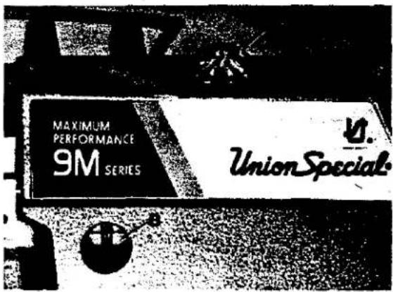
Use a straight mineral oil with a Saybolt viscosity of 90 to 125 seconds at 100 degrees F. This is equivalent to UNION SPECIAL Specification No. 175. Remove oil filler cap (A, Fig. 1), add oil until indicator is level with top line of sight gauge (B). Replace oil filler cap and run machine 30 - 40 seconds at half speed to fill the system. Check sight gauge and add oil as required until the indicator registers half way between the two lines of sight gauge (B). Approximately 14 to 16 ounces (354.9 to 414.0ml) is required to fill the system.
text_image
MAXIMUM PERFORMANCE 9M SERIES UnionSpecialFig. 1
LUBRICATION (Continued)
natural_image
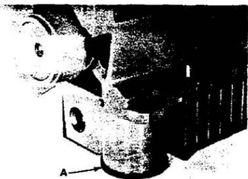
Black-and-white photo of a person in a suit with a labeled arrow pointing to the arm (no visible text or symbols)To maintain maximum recommended speed and servicability of this equipment when operating continuously, the oil must be changed at least every six months. In no case should oil remain in the machine for more than one year. Oil drain plug is located at rear of machine near bottom edge of base. ALWAYS change oil filter whenever oil is changed. It is recommended to change oil filter after the first three months of operation - or immediately, when oil is not visible in the oil filler cap while machine is running.
Fig. 2
NOTE: An oil by-pass valve is incorporated in the lubricating system so if oil filter should become clogged (oil not visible in filler cap while machine is running) machine will automatically revert to the splash system, but it is not advisable to operate for an extended length of time.
To replace filter, unscrew oil filter cover assembly (A, Fig. 2), which should only be hand tightened and remove filter from shaft of cover assembly. Due to tight tolerances, it may be necessary to screw the old filter off and the new filter on the shaft of the cover assembly. Replace cover assembly (hand tight) and recheck oil level.
NEEDLES
Each needle has both a type and size number. The type number denotes the kind of shank, point, length, groove, finish and other details. The size number, stamped on the needle shank, denotes the largest diameter of blade, measured midway between shank and eye. Collectively, type and size number represents the complete symbol, which is given on the label of all needles packaged and sold by Union Special.
To have orders promptly and accurately filled, forward the empty package, a sample needle, or the type and size number should be given. See description on packages. A complete order would read as follows: "1000 Needles, Type 154 GAS, Size 110/044". The type numbers of the needles recommended for each style of machine covered by this catalog are given in the machine style description. Other needles are available, but the ones indicated are those recommended to produce the most satisfactory results. The type number of the recommended needles, together with their description, and the sizes available are listed below:
| NEEDLE TYPE | DESCRIPTION | SIZES AVAILABLE |
| 154 GAS | Round shank, round point, curved blade, standard length, single groove, struck groove, spotted, chromium plated. | 055/022, 065/025, 070/027, 075/029, 080/032, 090/036, 100/040, 110/044, 125/049, 140/054, 150/060. |
| 154 GDS | Slabbed shank, round point, .060 inch (1.52mm) double slab, curved blade, standard length, double groove, struck groove, spotted, chromium plated. | 070/027, 075/029, 080/032, 090/036. |
| 154 GFS | Slabbed shank, round point, .046 inch (1.17mm) double slab, curved blade, standard length, single groove, struck groove, ball point, spotted, chromium plated. | 022, 065/025, 070/027, 075/029, 080/032, 040. |
| 162 SAS | Round shank, round point, curved blade, single groove, struck groove, spotted, chromium plated. | 055/022, 065/025, 070/027, 075/029, 080/032, 090/036, 100/040. |
NEEDLE REPLACEMENT
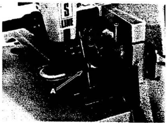
Rotate presser foot release bushing counterclockwise and swing presser foot to the left. Turn handwheel until needle(s) is at lowest position. Loosen needle clamp stud nut (A, Fig. 3) with socket wrench No. 21388 A.
Rotate handwheel until needle arm is in its highest position. Remove old needle(s) and insert new needle(s). Tighten nut (A), swing presser foot to the right and lock foot into sewing position with presser foot release bushing.
natural_image
Black-and-white photo of a mechanical device with labeled components (no readable text or symbols)Fig. 3
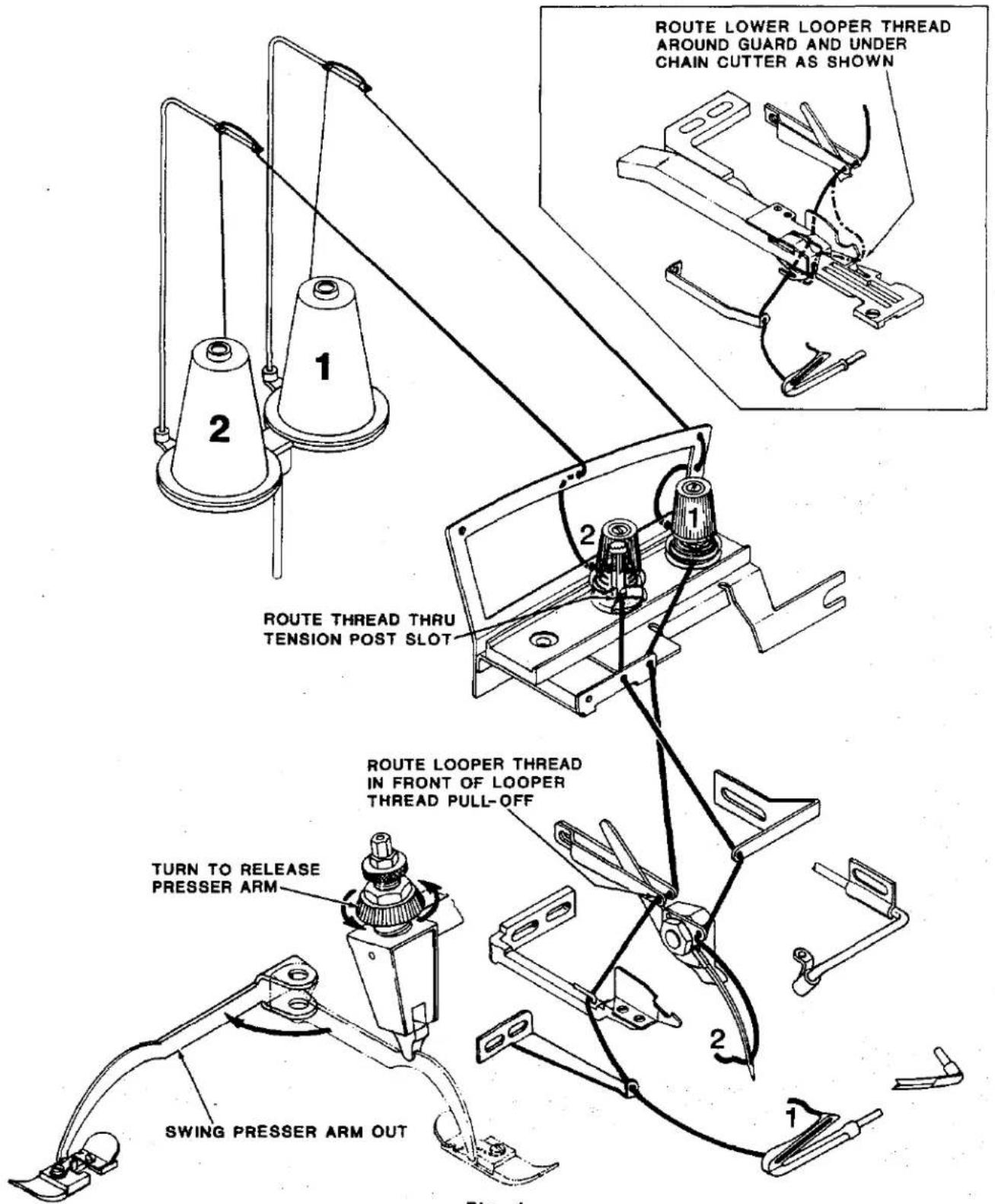
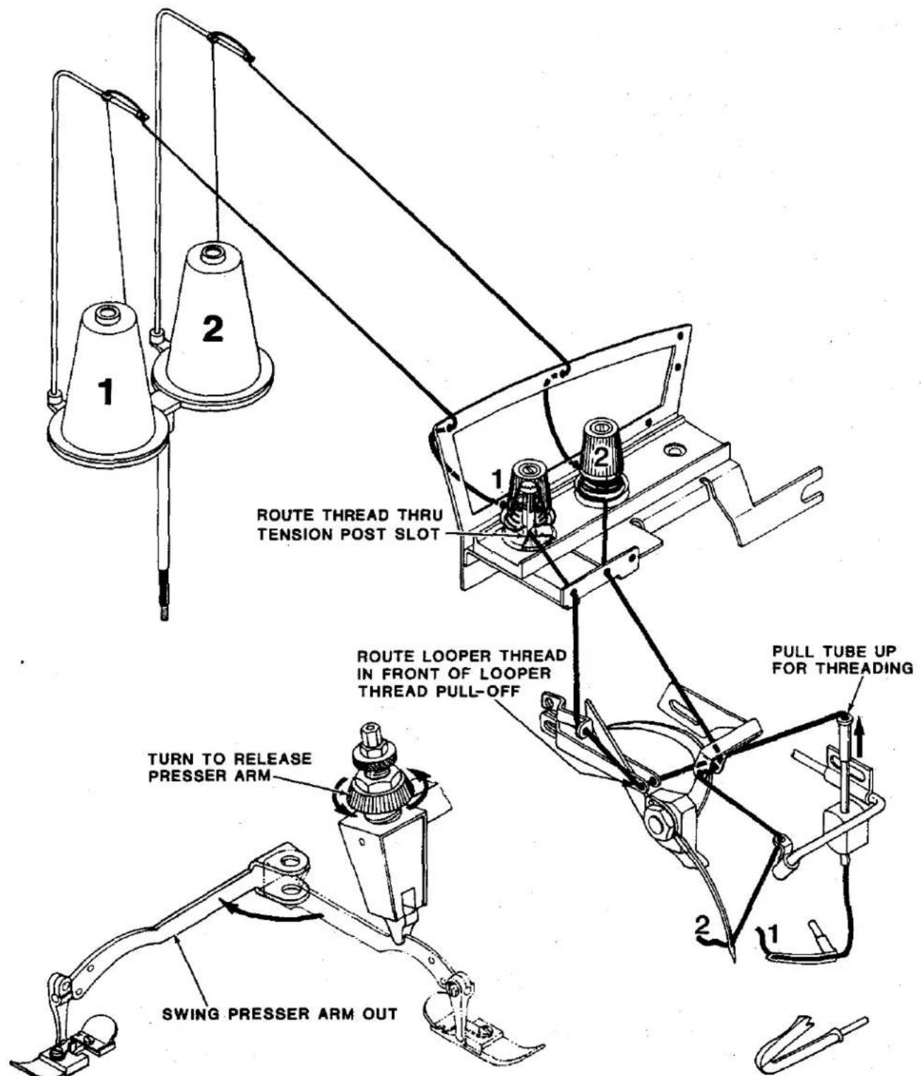
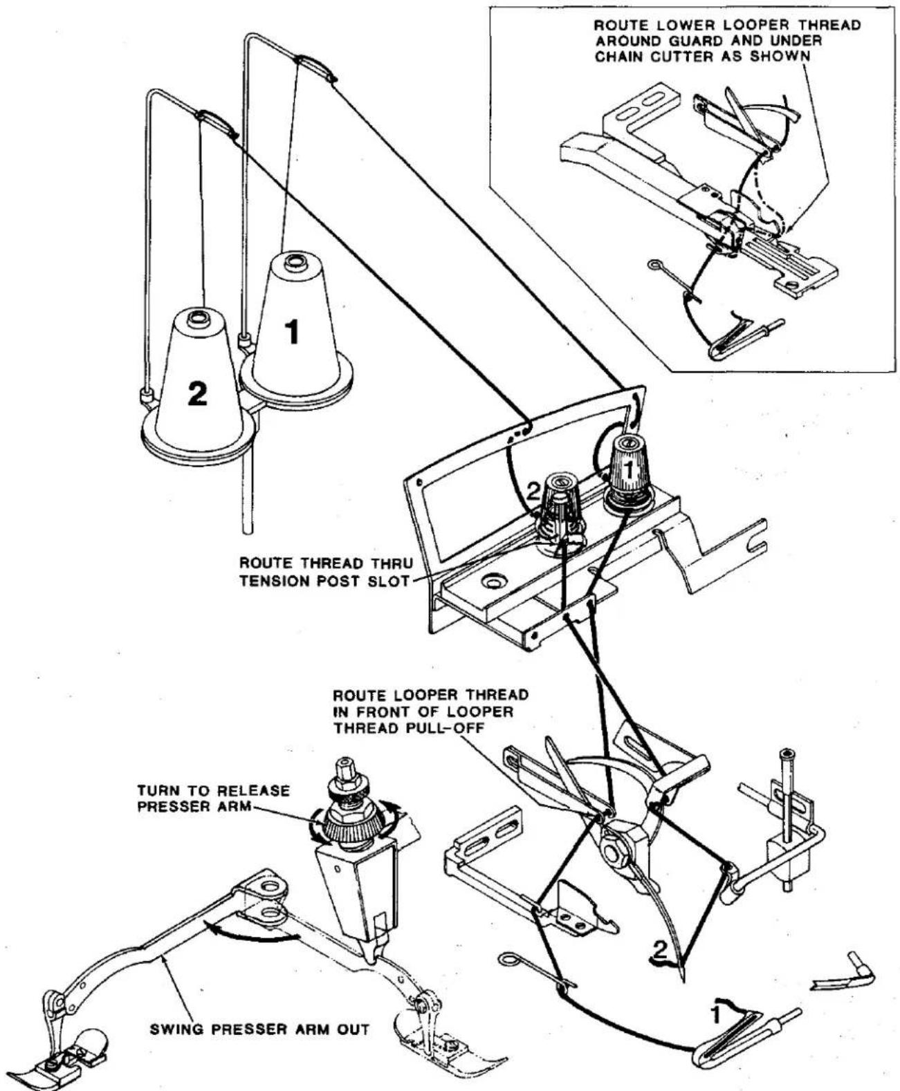
THREAD MACHINE AS INDICATED IN FIGURE 4 - 4E, AS APPLICABLE.
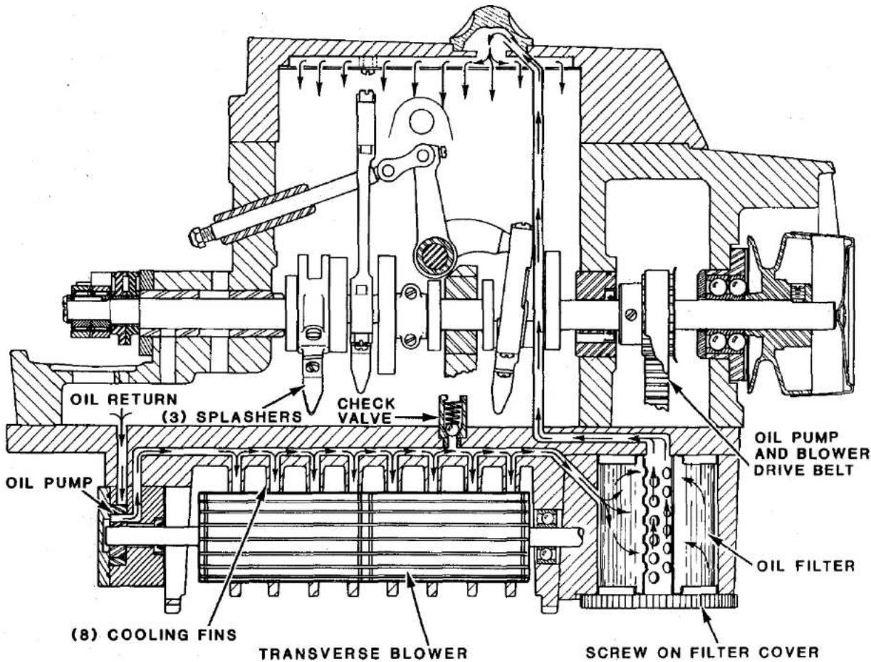
9M LUBRICATION AND COOLING FEATURES
text_image
OIL RETURN (3) SPLASHERS CHECK VALVE OIL PUMP (OIL FILTER) (OIL PUMP AND BLOWER DRIVE BELT) (OIL FILTER) (8) COOLING FINS TRANSVERSE BLOWER SCREW ON FILTER COVERTHREADING DIAGRAM FOR STYLES 39500 XQJ AND CXQJ
text_image
ROUTE LOWER LOOPER THREAD AROUND GUARD AND UNDER CHAIN CUTTER AS SHOWN ROUTE THREAD THRU TENSION POST SLOT ROUTE LOOPER THREAD IN FRONT OF LOOPER THREAD PULL-OFF TURN TO RELEASE PRESSER ARM SWING PRESSER ARM OUTFig. 4
THREADING DIAGRAM FOR STYLES 39500 XRN AND CXRN
text_image
ROUTE THREAD THRU TENSION POST SLOT ROUTE LOOPER THREAD IN FRONT OF LOOPER THREAD PULL-OFF PULL TUBE UP FOR THREADING TURN TO RELEASE PRESSER ARM SWING PRESSER ARM OUTFig. 4A
THREADING DIAGRAM FOR STYLES 39500 XSD AND CXSD
text_image
ROUTE LOWER LOOPER THREAD AROUND GUARD AND UNDER CHAIN CUTTER AS SHOWN ROUTE THREAD THRU TENSION POST SLOT ROUTE LOOPER THREAD IN FRONT OF LOOPER THREAD PULL-OFF TURN TO RELEASE PRESSER ARM SWING PRESSER ARM OUTFig. 4B
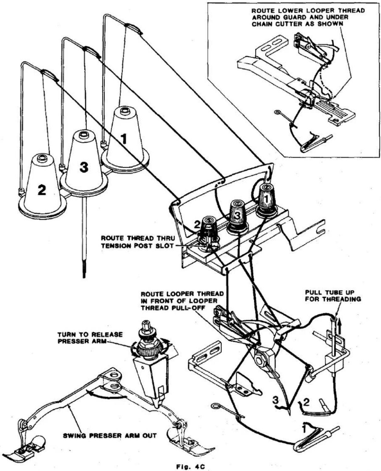
THREADING DIAGRAM FOR STYLES 39500 XQA, XQB, XTA, CXQA, CXQB, XSQB AND CXSQB
text_image
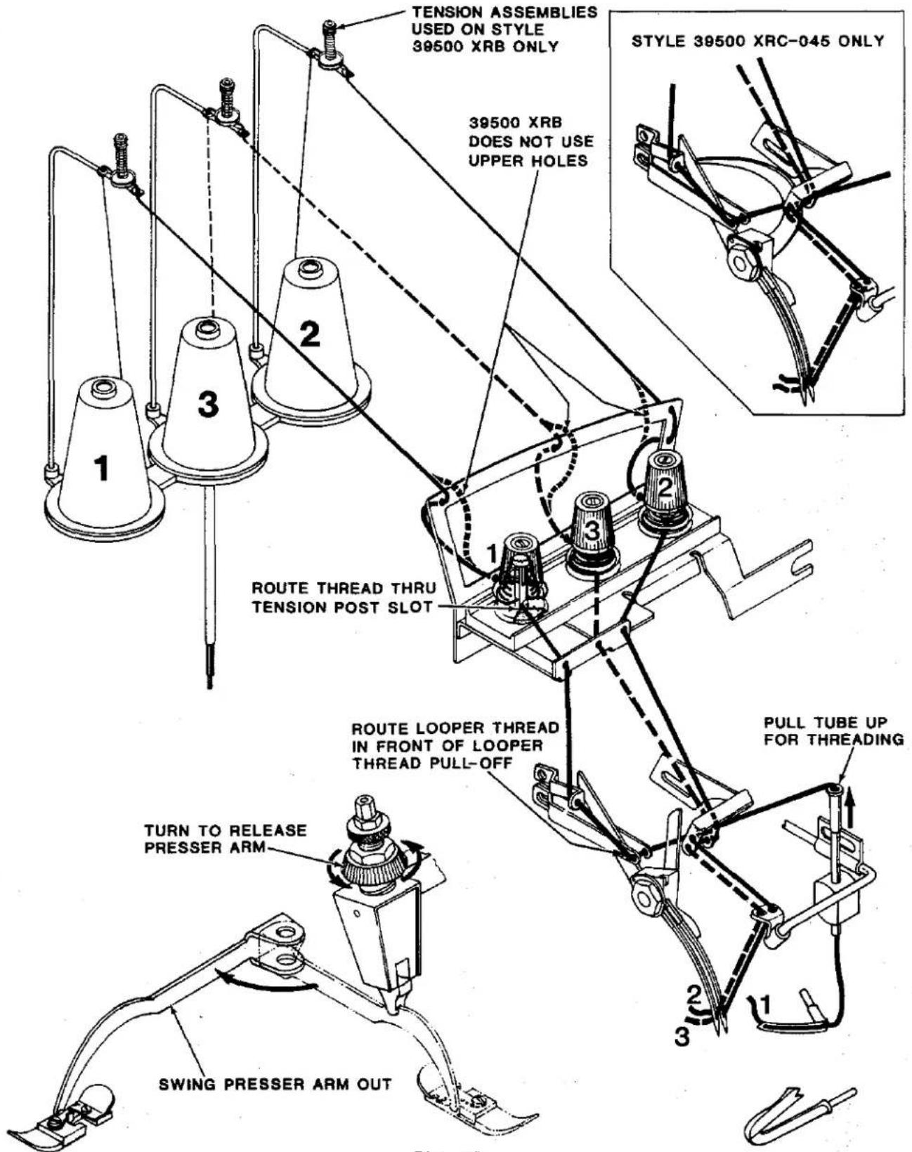
ROUTE LOWER LOOPER THREAD AROUND GUARD AND UNDER CHAIN CUTTER AS SHOWN ROUTE THREAD THRU TENSION POST SLOT ROUTE LOOPER THREAD IN FRONT OF LOOPER THREAD PULL-OFF PULL TUBE UP FOR THREADING TURN TO RELEASE PRESSER ARM SWING PRESSER ARM OUT Fig. 4CTHREADING DIAGRAM FOR STYLES 39500 XRB AND XRC-045
text_image
TENSION ASSEMBLIES USED ON STYLE 39500 XRB ONLY 39500 XRB DOES NOT USE UPPER HOLES STYLE 39500 XRC-045 ONLY ROUTE THREAD THRU TENSION POST SLOT ROUTE LOOPER THREAD IN FRONT OF LOOPER THREAD PULL-OFF PULL TUBE UP FOR THREADING TURN TO RELEASE PRESSER ARM SWING PRESSER ARM OUTFig. 4D
text_image
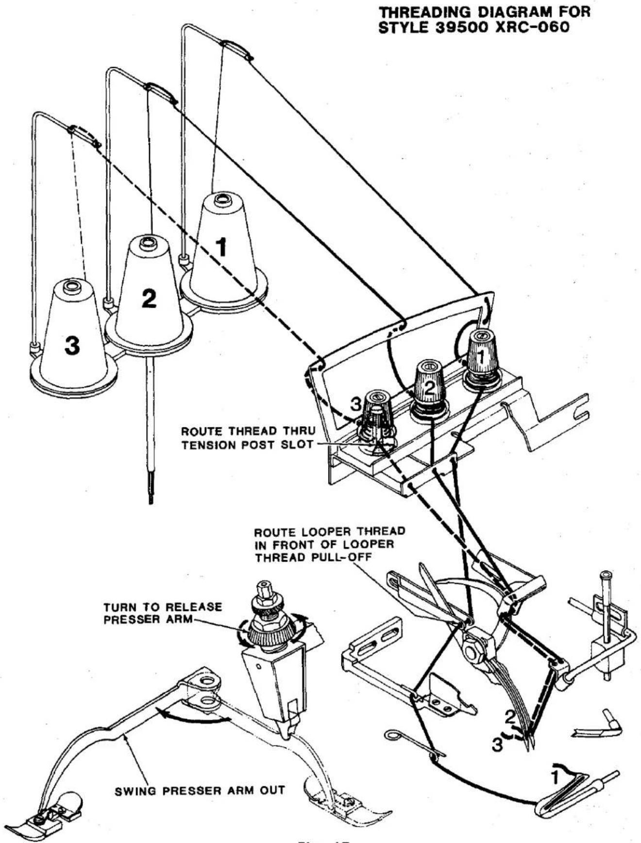
THREADING DIAGRAM FOR STYLE 39500 XRC-060 ROUTE THREAD THRU TENSION POST SLOT ROUTE LOOPER THREAD IN FRONT OF LOOPER THREAD PULL-OFF TURN TO RELEASE PRESSER ARM SWING PRESSER ARM OUTFig. 4E
NEEDLE ALIGNMENT
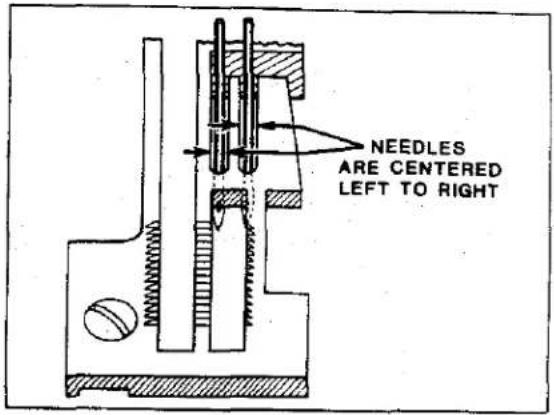
Needle(s) must center in needle slot(s) of throat plate, left to right, as shown in Fig. 5.
If adjustment is required, remove fabric guard and looper thread pull-off. Loosen needle driving arm clamp screw (A, Fig. 6) and reposition arm to the right or left as necessary. Temporarily tighten clamp screw, (A), then proceed to check needle(s) height.
text_image
NEEDLES ARE CENTERED LEFT TO RIGHTFig. 5
NEEDLE HEIGHT
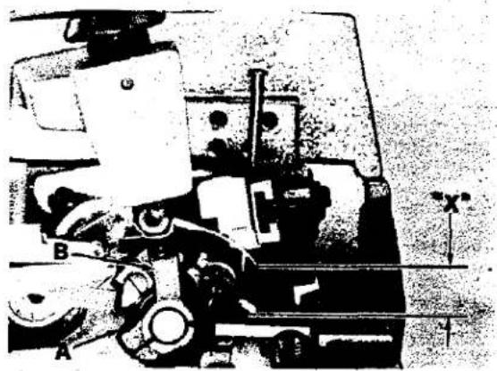
With needle driving arm at highest position, the tip of needle(s) should be "X" dimension from top of throat plate as shown in Fig. 6. See chart below.
Machine Styles
39500 XQA, XQB, XTA, CXQA, CXQB
39500 XQJ, CXQJ, XSQB, CXSQB
39500 XRB
39500 XRC-045
39500 XRC-060
39500 XRN, XSD, CXRN, CXSD
"X" Dimension
1/2 inch (12.7mm)
33/64 inch (13.1mm)
7/16 inch (11.1mm)
15/32 inch (11.9mm)
1/2 inch (12.7mm)
17/32 inch (13.5mm)
If adjustment is required, loosen clamp screw (A, Fig. 6) and reposition arm (B) forward or rearward as required to obtain "X" dimension being careful not to disturb "NEEDLE ALIGNMENT". Tighten clamp screw (A) and replace looper thread pull-off.
natural_image
Mechanical assembly diagram showing components like gears and shafts (no visible text or labels)Fig. 6
natural_image
Black-and-white photo of a mechanical assembly with labeled components (no readable text or symbols)Fig. 7
text_image
1/8" (3.2 mm) OR 3/32" (2.4mm)Fig. 8
text_image
Technical diagram of a mechanical device with labeled parts A through F and directional arrows indicating movement or force.Fig. 9
CLOTH PLATE
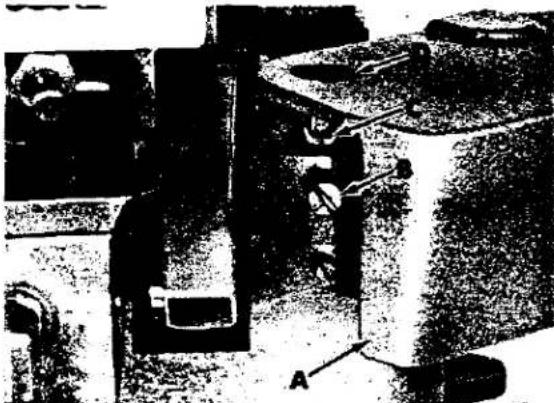
Remove cloth plate (A, Fig. 7) by loosening screw (B) and lifting upward with stud (C) and screw (D) assembled to cloth plate.
Before replacing cloth plate, hold stud (C) and tighten screw (D) only enough to remove end play, yet allowing cloth plate to swing open when assembled. Assemble cloth plate to machine by inserting stud (C) with flat and "V" notch to the rear into hole of machine bed. Tighten screw (B) to press "V" notch of stud (C) against screw (D).
LOWER LOOPER/SPREADER
PRIOR TO CHECKING, REMOVE FRONT AND REAR NEEDLE GUARDS. REMOVE CHIP GUARD AND HEMMER ASSEMBLY ON STYLES 39500 XRN, XSD, CXRN, CXSD. REMOVE CHIP GUARD ON STYLE 39500 XRC.
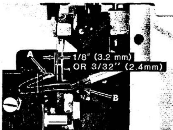
With looper/spreader at EXTREME left end of travel, the distance from its point to the centerline of needle (or LEFT needle) should be 1/8 inch (3.2mm) on all Styles except 39500 XRN, XSD, CXRN and CXSD. Dimension for these Styles should be 3/32 inch (2.4mm). Gauge No. 21225-1/8 or 21225-3/32 could be used advantageously in checking this setting.
If adjustment is required, position looper/spreader (A, Fig. 8) to extreme right and loosen clamp nut (B). Position looper/spreader to EXTREME left end of travel and adjust same in or out of looper/spreader shaft to obtain specified dimension.
Rotate handwheel to position looper/spreader point into scarf of needle (or LEFT needle). Set point to TOUCH but NOT DEFLECT needle(s), then rotate handwheel to position looper/spreader to the right and tighten clamp nut (B).
REAR NEEDLE GUARD
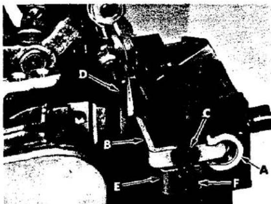
Remove spring from inside of lower knife holder (A, Fig. 9), then reassemble knife
holder into throat plate support block. Replace rear needle guard (B) using screw (C) with front edge of guard centered in slot of knife holder as shown. Temporarily tighten screw (C) to hold guard in position, yet allowing guard to be adjusted. Rotate handwheel in operating direction until lower looper/spreader (D) travels from extreme left into scarf of needle(s). Set guarding SURFACE of needle guard (B) as low as possible to prevent it from interfering with needle thread as loop is being formed to rear of needle(s), then tighten screw (C) securely. Guard must NOT interfere with lower knife holder movement or come in contact with lower looper/spreader at any point of travel.
FRONT NEEDLE GUARD
Replace front needle guard (E, Fig. 9) using screw (F). Temporarily tighten screw (F) to hold guard in position, yet allowing guard to be adjusted. Rotate handwheel in operating direction until needle(s) is at lowest position. Set guarding SURFACE of needle guard (E) to needle(s) with minimum clearance - approximately .004 inch (.10mm) and tighten screw (F) securely. Check to ensure needle(s) is NOT being pinched between front and rear needle guards.
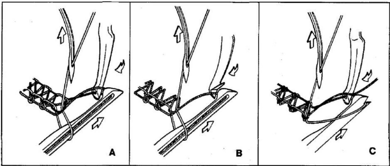
Rotate handwheel in operating direction and closely observe the path of the upper looper/spreader as it moves from extreme right position and approaches lower
text_image
A B CFig. 10
looper (Fig. 10). Point of upper looper or thread pick up on a spreader must pass the notch in head of lower looper with minimum clearance. Upper looper should pass under the lower looper thread (A, Fig. 10) and a spreader must pick up lower looper thread with lower point (B). On Style 39500 XRN, CXRN, the upper looper should pass under the lower spreader thread (C).
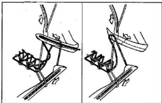
Continue rotating handwheel until upper looper/spreader reaches the extreme left position at the needle (Fig. 11). At this point the upper looper should be in position so the descending needle(s) will pass to the right of the upper looper thread which extends from the eye of the looper to the previously formed stitch.
On machines using a spreader, the spreader should now be in position so the descending needle(s) will pass to the right of the lower looper thread extending from the notch of the spreader to the previously formed stitch. THE UPPER LOOPER/SPREADER SHOULD NOT RUB AGAINST THE LOWER LOOPER OR NEEDLE(S) AT ANY POINT OF TRAVEL.
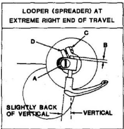
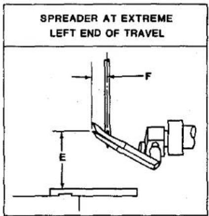
Figures 12, 13, 14, and the chart following relate approximate dimensions for adjusting upper looper/spreader at their extreme right and left positions of travel.
natural_image
Technical line drawing of a mechanical device with two views (top and side), showing no text or symbols.Fig. 11
UPPER LOOPER/SPREADER (Continued)
| MACHINE STYLE | SHANK EXTENDED ABOVE HOLDER | HEIGHT ABOVE THROAT PLATE | POINT TO LEFT OF NEEDLE CENTERLINE |
| 39500 XQA, XQB, XQJ, XTA, CXQA, CXQB, CXQJ, XSQB, CXSQB | "B"Fig. 12 | "E"Fig. 13 - 14 | "F"Fig. 13 - 14 |
| 1/32 to 1/16"( .8 to 1.6mm) | 31/64"(12.3mm) | 5/32"(4.0mm) | |
| 39500 XRB | 1/64 to 1/32"( .4 to .8mm) | 7/16"(11.1mm) | 5/32"(4.0mm)left needle |
| 39500 XRC-045 | 1/64 to 1/32"( .4 to .8mm) | 15/32"(11.9mm) | 5/32"(4.0mm)left needle |
| 39500 XRC-060 | 1/32 to 1/16"( .8 to 1.6mm) | 15/32"(11.9mm) | 9/64"(3.6mm)left needle |
| 39500 XRN, CXRN | 1/16 to 3/32"(1.6 to 2.4mm) | 33/64"(13.0mm) | 5/32"(4.0mm) |
| 39500 XSD, CXSD | 1/32 to 1/16"( .8 to 1.6mm) | 1/2"(12.7mm) | 5/32"(4.0mm) |
To adjust upper looper/spreader, follow instructions in sequence as listed:
- Position upper looper/spreader at the left end of travel, loosen clamp screw (A, Fig. 12) and set upper looper/spreader shank to dimension "B" above holder, then temporarily tighten screw (A).
- With upper looper/spreader positioned at the right end of travel, loosen screw (C) and rotate holder (D) as required to set shank slightly back of vertical on all Styles except 39500 XQJ and CXQJ, as shown in Fig. 12, then temporarily tighten screw (C). Shank of spreader on Styles 39500 XQJ and CXQJ should be set vertical.
text_image
LOOPER (SPREADER) AT EXTREME RIGHT END OF TRAVEL SLIGHTLY BACK OF VERTICAL VERTICALFig. 12

text_image
LOOPER AT EXTREME LEFT END OF TRAVEL F EFig. 13
text_image
SPREADER AT EXTREME LEFT END OF TRAVEL F EFig. 14
UPPER LOOPER/SPREADER (Continued)
- Rotate handwheel in operating direction bringing the upper looper/spreader into the LOWER looper. The POINT of upper looper or THREAD PICK-UP of upper spreader should be set to enter the notched area behind the head of the lower looper, See Fig. 10.
- Continue to rotate handwheel in operating direction until upper looper/spreader is at extreme LEFT end of travel. Rotate upper looper/spreader holder as required to position POINT of upper looper to dimension "E", Fig. 13 or LOWER POINT of upper spreader to dimension "E", Fig. 14 from top of throat plate.
- With upper looper/spreader still positioned at left end of travel, it may be necessary to move looper/spreader holder in or out of its shaft to set POINT of looper dimension "F", Fig. 13 or LOWER POINT of spreader dimension "F", Fig. 14, which is to the left of centerline of needle (or left needle). Tighten screw (C, Fig. 12), then screw (A) securely.
- If the needle(s) is being deflected by the upper looper/spreader, clearance to the needle(s) can be increased by reducing the length of looper/spreader shank above holder (dimension "B"), See Step 1. It will then be necessary to slightly reduce the angle of the shank back of vertical, See Step 2. Set looper/spreader to lower looper, See Step 3. Reversing this procedure will position the looper/spreader closer to the needle(s).
MAIN AND DIFFERENTIAL FEEDS
ASSEMBLE MAIN, DIFFERENTIAL, CHAINING FEEDS AND THROAT PLATE TO MACHINE, AS APPLICABLE.
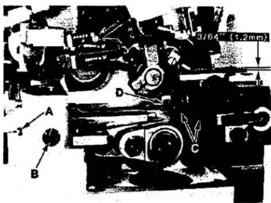
Rotate handwheel in operating direction until teeth of rising feeds are above the top surface of throat plate. The feeds should be level with throat plate at this time. With feeds at highest position of travel, their teeth should extend approximately 3/64 inch (1.2mm) above throat plate as shown in Fig. 15.
text_image
3/64" (1.2mm) A B D CFig. 15
If adjustment is required, loosen lock screw (A) and rotate tilt adjusting pin (B) as required to level feeds, then tighten lock screw (A). Loosen feed attaching screws (C) and adjust feeds up or down to obtain proper height above throat plate as shown in Fig. 15, then tighten screws (C).
On all Styles fitted with separate chaining feeds, with feeds at highest position, loosen screw (D) and set height of chaining feed even with the stitch tongue of throat plate, then tighten screw (D).
LOWER KNIFE
text_image
Black-and-white technical diagram with labeled components and annotations, likely from an engineering or mechanical drawing.Fig. 16
INSERT SPRING BACK INTO LOWER KNIFE HOLDER AND ASSEMBLE HOLDER TO THROAT PLATE SUPPORT.
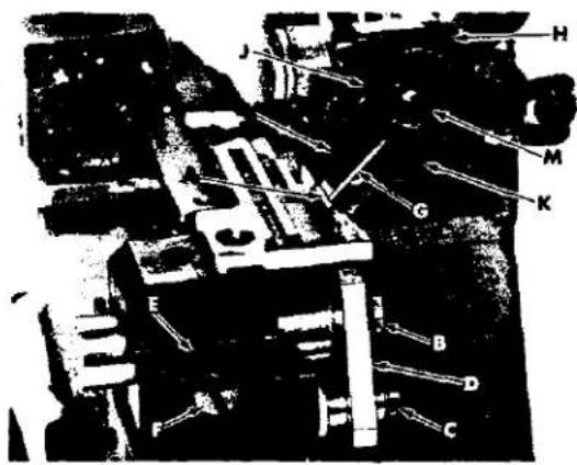
Cutting edge of knife (A, Fig. 16) must be even and parallel with top surface of throat plate. Examine sewn sample for specified seam width and appearance. If adjustment is required, loosen screw (B) and adjust knife (A) up or down until its cutting edge is flush with top of throat plate, then tighten screw (B).
If cutting edge of knife is tilted, loosen screw (C) and rotate holder (D) front to rear as required, then tighten screw (C). Holder MUST move freely, left to right, and NOT bind with needle guard centered in slot of knife holder. Adjust knife (A), left to right, by loosening locknut (E), screw (F) and set knife to specified seam width by measuring from center of needle to cutting edge of knife. Hold knife in this position and tighten screw (F).
Adjust UPPER KNIFE: then sew-off on a piece of selected material to further check adjustment, by measuring the distance from needle penetration to edge of material. Readjust if necessary, to obtain specified seam width or appearance.
NOTE: See shear angle adjustment
UPPER KNIFE
REMOVE NEEDLE(S) AND RE-ASSEMBLE UPPER KNIFE HOLDER INTO SLOT OF UPPER KNIFE DRIVING ARM. ALSO RE-ASSEMBLE UPPER KNIFE IN HOLDER AND HOLD KNIFE FIRMLY IN POSITION.
At lowest position the front tip of upper knife cutting edge must extend 1/64 - 1/32 inch (.4 - .8mm) below cutting edge of lower knife. If adjustment is required, rotate handwheel to position upper knife driving arm at lowest position; with upper knife (G, Fig. 16) at lowest position of travel and while holding upper knife firmly against lower knife, adjust knife holder (H) left to right, to position front tip of upper knife cutting edge 1/64 - 1/32 inch (.4 - .8mm) below cutting edge of lower knife, then tighten screw (J).
Assemble knife clamp (K) and chain guard (L) in position using nut (M). Set chain guard (L) against top surface of upper knife and slightly back of its cutting edge, then tighten nut (M). Loosen screw (F) to enable spring pressed lower knife to move freely left to right. If desired, the lower knife can be locked in position by tightening screw (F) against knife holder.
NOTE: Locking nut (E) must be tightened to hold screw (F) in position; screw (F) also serves as a latch pin for cloth plate.
SHEAR ANGLE ADJUSTMENT
BE SURE LOWER AND UPPER KNIVES ARE ADJUSTED PROPERLY BEFORE SETTING SHEAR ANGLE.
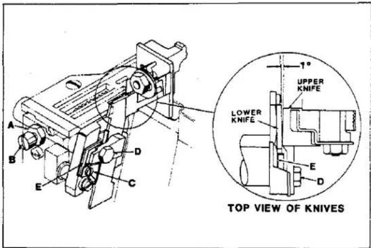
With upper knife at lowest position, the proper shear angle between cutting edge of upper and lower knives is 1 degree as shown in Fig. 17. Approximately equivalent to a .003 inch (.076mm) feeler gauge at this point. Best results are obtained if both knives are properly sharpened prior to adjusting.
text_image
A B C D E TOP VIEW OF KNIVES 1° UPPER KNIFE LOWER KNIFE E DIf adjustment in required, remove throat plate, loosen locknut (A)
and lock lower knife holder out of position away from upper knife with screw (B). Loosen screw (C), clamp screw (D) and adjust (wedge) guide plate (E) forward or rearward as required to angle top front edge of lower knife to attain proper shear angle. Hold guide plate (E) in position while tightening screw (C) and clamping screw (D). Loosen screw (B) allowing lower knife holder to float left to right, tighten locknut (A) and replace throat plate.
PRESSER FOOT ALIGNMENT
LOCK THE PRESSER FOOT IN SEWING POSITION AND ROTATE HANDWHEEL UNTIL NEEDLE(S) IS AT LOWEST POSITION.
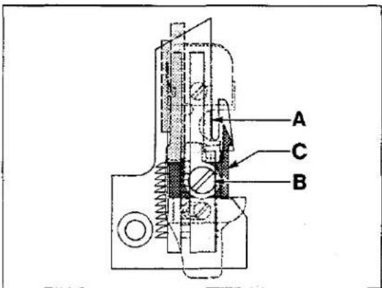
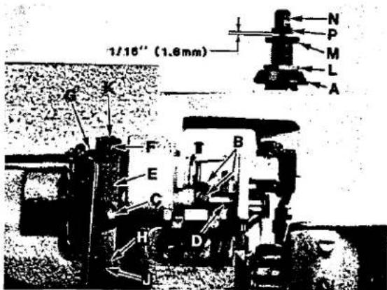
Right edge of presser foot must align with left edge of needle slot in throat plate as shown Ref. Point A, Fig. 18. Presser foot must lie flat on throat plate. The adjustable stitch tongue on presser foot must center over stitch tongue of throat plate as shown in Fig. 18. If adjustment is required, lock presser foot in sewing position by release bushing (A, Fig. 19), loosen collar screws (B) and clamp screw (C), then adjust lifter lever shaft (D) left to right until the right edge of presser foot aligns with the left edge of needle slot in throat plate as shown in Ref. Point A, Fig. 18. Tighten collar screws (B, Fig. 19) and while holding lifter lever arm (E) so its stop screw (F) is against intermediate lever (G), tighten clamp screw (C). Completely unlock release bushing (A, Fig. 19). Plunger should clear presser arm without binding. Loosen screw (B, Fig. 18) and adjust stitch tongue (C) left to right, to center over stitch tongue of throat plate as shown in Fig. 18, then tighten screw (B). On all Styles except 39500 XQJ, XRB, XRC, and CXQJ; a pivot type presser foot shank allows precise adjustment of presser foot, forward - rearward and flatness on throat plate for optimum feeding.
Fig. 17
text_image
A C BFig. 18
text_image
1/10" (1.8mm) N P M L A G K F E C H D JFig. 19
PRESSER FOOT LIFT
Lift presser foot to highest position and rotate handwheel in operating direction. Upper looper/spreader must not contact presser foot at any point of travel. If adjustment is required, loosen locknut (H, Fig. 19) and adjust stop screw (J) so presser foot will not interfere with upper looper/spreader, then tighten locknut (H). Loosen locknut (K) and set stop screw (F) on upper end of lifter lever arm so there is approximately 1/16 inch (1.6mm) free motion in lifter lever before presser foot starts to rise, then tighten locknut (K).
PRESSER FOOT PRESSURE
Sufficient pressure must be maintained to feed work uniformly. Excessive spring pressure will cause feeds and presser foot to wear prematurely when chaining. If adjustment is required, rotate handwheel in operating direction until both main and differential feeds are positioned below throat plate. Loosen locknut (L, Fig. 19) and turn adjusting screw (M) clockwise for more pressure or counterclockwise for less pressure, then tighten locknut (L).
NOTE: Adjusting screw (M) will effect the function of pressure release bushing (A). Plunger must clear presser arm when pressure release bushing is unlocked. When release bushing is locked in position, presser foot must be held firmly against throat plate. If these conditions do not exist the following adjustment must be made.
Lock presser foot in position with pressure release bushing (A); loosen capnut (N) and adjust nut (P) up or down so its under surface is 1/16 inch (1.6mm) above screw (M) as shown in Fig. 19. Hold nut (P) in position and tighten capnut (N).
HEMMING GUIDE SUPPORT BRACKET (STYLES 39500 XRN, XSD, CXRN, CXSD)
text_image
Technical diagram of a mechanical assembly with labeled parts A through FFig. 20
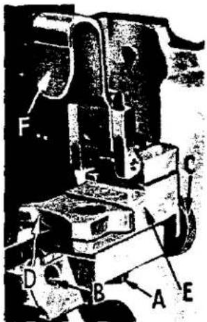
Loosen lock screw (A, Fig. 20), then proceed as follows;
Assemble the hemming guide support bracket onto the lower knife support bracket by means of screw (B, Fig. 20). With the knurled adjusting screw (C), set the edge guide (D) so that the left side of its tip is even with and parallel to the right side of the right feed slot in the throat plate. When the edge guide tip is in this position, the front or leading edge should be slightly to the right of parallel.
natural_image
Black-and-white photo of a military vehicle with mounted equipment (no visible text or symbols)Fig. 21
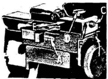
This adjustment can be made by positioning the stop screw (A, Fig. 21) located towards the front of the hinge block and edge guide support bracket (E, Fig. 20). Under normal conditions, the edge guide is spring loaded to compensate for the differences in the material thickness. The amount of movement and pressure applied to the edge guide tip can be set by removing lock screw (B, Fig. 21) and adjusting the screw which presses against the spring and pin, located in the hinge block and edge guide support bracket (E, Fig. 20). Replace lock screw and tighten securely. If movement of the edge guide is not required, then remove lock screw (B, Fig. 21), set screw and spring; then replace set screw and lock screw. Be sure set screw is tightened against pin and lock screw is tightened against set screw.
FINAL ADJUSTMENT OF HEMMING GUIDE
(STYLES 39500 XRN, XSD, CXRN AND CXSD)
Adjust the edge guide (D, Fig. 20) by turning the knurled adjusting screw (C) so that the stitches are located in the folded edge, yet do not show on the face of the fabric. At this point re-tighten screw (A, Fig. 20) securely. Adjust the overhanging guide (F, Fig. 20) so that space between its guiding edge and the edge guide (D) corresponds with the thickness of the material to be hemmed. Loosen set screw (C, Fig. 21) and holding screw (D), now move the hinge block (E) to obtain the proper distance between the edge guide and the overhanging guide. Re-tighten screws (C) and (D). Remove lock screw (F) and adjust stop screw that is in front of lock screw, so that the tip of the overhanging guide is located at the center of the edge guide vertically. Replace lock screw (F) and tighten against stop screw.
SETTING STITCH LENGTH
(ALL STYLES EXCEPT 39500 XQJ, CXQJ)
Length of stitch is determined by the combination of feed eccentrics used. Outer (left) eccentric (A, Fig. 22) actuates main (rear) feed dog while inner (right) eccentric (B) actuates differential (front) feed dog.
When assembling feed eccentrics, be sure hubs are facing each other and be careful not to damage shaft or key. To replace feed eccentrics, remove screw (C), and spacer (D) from end of shaft (E).
Turn handwheel in operating direction to position key groove in eccentric towards the front and using hooked eccentric extractor supplied with machine, reach behind eccentrics and withdraw same, while rocking handwheel slightly back and forth. If eccentrics are unusually tight fitting, it may be necessary to remove nut (F) and feed driving connection (G); possibly nut (H) and connection (J). Then continue as originally suggested.

text_image
E J H B G F A D CFig.22
text_image
E G F A B D CFig. 23

text_image
Technical diagram of a mechanical assembly with labeled parts A, B, C, and DFig. 24
SETTING STITCH LENGTH (STYLES 39500 XQJ, CXQJ)
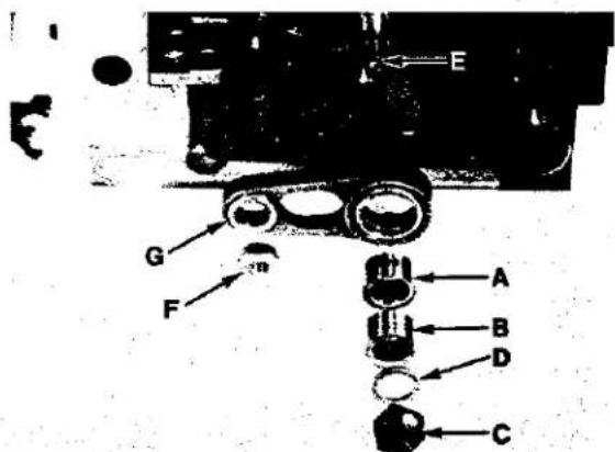
When assembling feed eccentric (A, Fig. 23) and eccentric spacer (B), be sure hubs are facing each other and be careful not to damage shaft or key. To replace feed eccentric, remove screw (C), crankshaft spacer (D) and eccentric spacer (B) from end of shaft (E). Turn handwheel in operating direction to position key groove in eccentric towards the front and using hooked eccentric extractor supplied with machine, reach behind eccentric and withdraw same, while rocking handwheel slightly back and forth. If eccentric is unusually tightly fitted, it may be necessary to remove nut (F) and feed driving connection (G), then continue as originally suggested.
NEEDLE THREAD CONTROL
Needle thread is controlled by needle thread eyelet (A, Fig. 24) and needle thread cam pull-off (B). Needle thread eyelet is set so the securing screw is centered in the screw slot, front to back. Raise or lower the eyelet to have needle thread barely touch needle thread cam pull-off when needle carrier is in its lowest position.
Moving the eyelet up and back increases the needle thread in the stitch, moving the eyelet down and forward acts the reverse. To adjust needle thread control, loosen screw (C) and position thread eyelet (A) as required. Hold eyelet in position and tighten screw (C).
LOOPER THREAD PULL-OFF
Clearance between looper thread pull-off (D, Fig. 24) and needle thread cam pull-off (B) should be only enough to ensure proper take-up of looper thread as shown in Fig. 24. Loosen screws (E) and rotate looper thread pull-off lever (F) front to back on needle driving shaft until proper clearance is obtained. Before tightening screws (E) be sure to take up all end play in needle drive shaft.
LOOPER THREAD CONTROL
text_image
When a normal amount of looperFig. 25
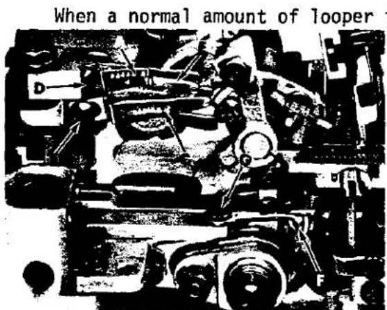
thread is drawn, upper and lower looper threads will be a little slack when needle(s) is at highest position (lower looper thread only for Styles 39500 XQJ, XRN, XSD, CXQJ, CXRN, CXSD). The auxiliary upper looper thread guide (A, Fig. 25) should be centered in its adjusting slot and set slightly above a horizontal position. Loosen screw (B, Fig. 25). Center lower looper thread eyelet (C) in its adjusting slot and set eyelet in a horizontal position.
Hold eyelet (C) in position and tighten screw (B). On all Styles except 39500 XQJ, XRN, XSD, CXQJ, CXRN, CXSD; loosen screw (D).
LOOPER THREAD CONTROL (Continued)
Center upper looper thread eyelet (E) in its adjusting slot and set eyelet so it rests on the top surface of lower looper thread eyelet and back of lower looper thread eyelet eye. Center auxiliary upper looper thread guide (A) in its adjusting slot and set guide so it is slightly above a horizontal position. Hold upper looper thread eyelet (E) and auxiliary upper looper thread guide (A) in position and tighten screw (D). To set frame lower looper thread eyelet (F) loosen screw (G) and position the eyelet so the looper thread is held in a straight line to the lower looper. Tighten screw (G).
NOTE: Moving eyelets (C and E) to the rear increases the amount of looper thread in the system and moving them forward reduces the amount of thread in the system.
POWER "AIR-KLIPP" CHAIN CUTTER ADJUSTMENTS
SETTING KNIFE CROSS OVER
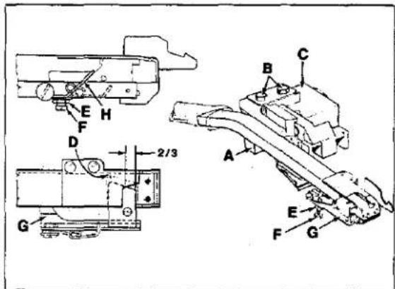
The knife cross over is set at the factory, however adjustment will be necessary after replacing or repairing knives. With sewing motor switch in "OFF" position and air line connected to air motor for "AIR-KLIPP" chain cutter (see setting pressure valve) depress treadle until air motor begins to operate, in and out. With forefinger, carefully press against the moving drive link (A, Fig. 26) until air motor stops.
With treadle still depressed, check the knife cross over. The cross over of the lower knife to the upper knife is positioned correctly, when the lower knife is 2/3 from the front of the upper knife as shown in Fig. 26. If adjustment is required, loosen screws (B), reposition air motor (C) slightly to the left if lower knife is positioned to far left or slightly to the right if lower knife is positioned too far right. Retighten screws (B) and recheck cross over.
CAUTION! Check to ensure that lower knife does not strike against inside of "AIR-KLIPP" chain cutter tube. A slight clearance must be provided at point (D).
SETTING KNIFE CUTTING
If adjustment is required, loosen nut (E) and turn lower knife adjusting screw (F) clockwise (a small amount at a time) while manually operating knife lever (G), continuously checking with a piece of thread to see if knives are cutting. As soon as the knives fail to cut the thread and the shear angle is zero, turn screw (F) counterclockwise approximately 1/4 turn and lock with nut (E). Check cutting action of knives with sewing motor switch "ON".
SETTING KNIFE PRESSURE
Torsion spring (H) initially should be horizontal in its free state and then lifted over the knife. More pressure can be obtained by bending spring (H) slightly to the left (away from lower knife); less pressure - by bending spring slightly to the right (towards lower knife).
SETTING PRESSURE VALVES
Regulate valve on pneumatic control device for air motor of the "AIR-KLIPP" chain cutter to approximately 20-22 psi (1.5 bar) when air motor is operating. Regulate valve on pneumatic control device for the suction air to obtain maximum suction, yet so that the FABRIC TO BE SEWN will not be cut by the "AIR-KLIPP" chain cutter knives.
text_image
Technical diagram of a mechanical assembly with labeled components and dimensional annotationsFig. 26
text_image
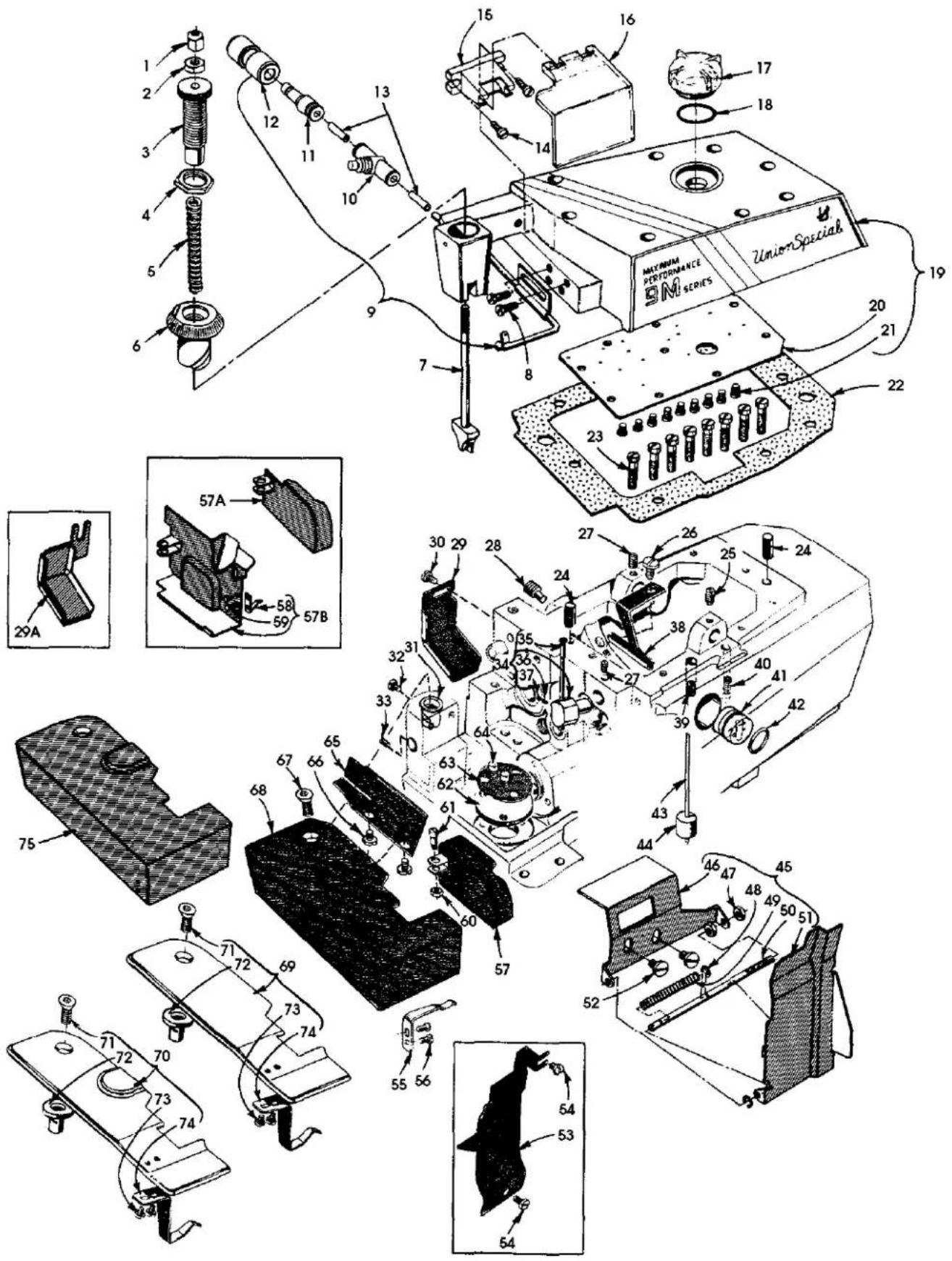
Technical diagram of a sewing machine with numbered parts and exploded views, including assembly lines and component labels.MAIN FRAME, PRESSER FOOT RELEASE PARTS,
MISCELLANEOUS COVERS AND PLATES
| Ref.No. | PartNo. | Description | Amt.Req. |
| 1 | 39557 B | Nut, cap, presser spring plunger | 1 |
| 2 | 39557 E | Nut, locking | 1 |
| 3 | 39557 C | Screw, adjusting | 1 |
| 4 | 39557 F | Nut, lock, adjusting screw | 1 |
| 5 | 39557 H | Spring, presser | 1 |
| 6 | 39556 A | Bushing, presser foot release | 1 |
| 7 | 39557 A | Plunger, presser spring | 1 |
| 8 | 22569 B | Screw, needle cooler and thread eyelet | 2 |
| 9 | GR-21237 CR | Cooler, needle all Styles except XRB, XRC | 1 |
| - | GR-21237 DK | Cooler, needle, Styles XRB, XRC | 1 |
| 10 | 671-168 | Flow control | 1 |
| 11 | 671F82H | Reducer | 1 |
| 12 | 671F86D | Fitting | 1 |
| 13 | 6-878-4 | Tubing, .65mm long | 1 |
| 14 | 22585 R | Screw | 2 |
| 15 | 21695 AT | Bracket, mounting | 1 |
| 16 | 21695 AU | Shield, sewing | 1 |
| 17 | 39594 Y | Cap, oil fill | 1 |
| 18 | 660 705 | "0" Ring | 1 |
| 19 | 39582 DV | Cover, top | 1 |
| 20 | 39582 DS | Plate, oil drip | 1 |
| 21 | 22564 D | Screw | 9 |
| 22 | 39582 BZ | Gasket, top cover | 1 |
| 23 | 22541 | Screw, top cover | 8 |
| 24 | 667 D-8 | Pin, dowel | 2 |
| 25 | 22565 S | Screw, spot, upper looper drive lever shaft | 1 |
| 26 | 22569 D | Screw | 1 |
| 27 | 22565 | Screw, set, upper thread tube assembly and upper looper drive lever shaft | 2 |
| 28 | 22571 E | Screw, oil drain plug | 1 |
| 29 | 39534 R | Shield, oil, feed bar, all Styles w/o Power "AIR-KLIPP" chain cutter | 1 |
| 29A | 39534 RB | Shield, oil, feed bar, all Styles w/Power "AIR-KLIPP" chain cutter | 1 |
| 30 | 90 | Screw | 1 |
| 31 | 39501 K | Stud, cloth plate, all Styles except XRN, XSD, CXRN, CXSD | 1 |
| 32 | 22569 | Screw, locking, cloth plate stud | 1 |
| 33 | 22565 F | Screw, locking, feed adjusting pin | 1 |
| 34 | 29477 GW | Thread Tube Assembly, upper looper | 1 |
| 35 | 39568 G | Tube, thread | 1 |
| 36 | 39568 J | Spring, tension | 1 |
| 37 | 22743 | Screw, set | 1 |
| 38 | 39594 R | Plate, oil collector | 1 |
| 39 | 22569 K | Screw, oil gauge | 1 |
| 40 | 22894 AE | Screw, set, lower looper bar driving lever shaft | 2 |
| 41 | 39593 H | Gauge, oil | 1 |
| 42 | 660-243 | Ring, oil seal | 1 |
| 43 | 39593 D | Indicator, oil gauge | 1 |
| 44 | 39593 C | Float, oil gauge | 1 |
| 45 thru 76 | See following page | ||
text_image
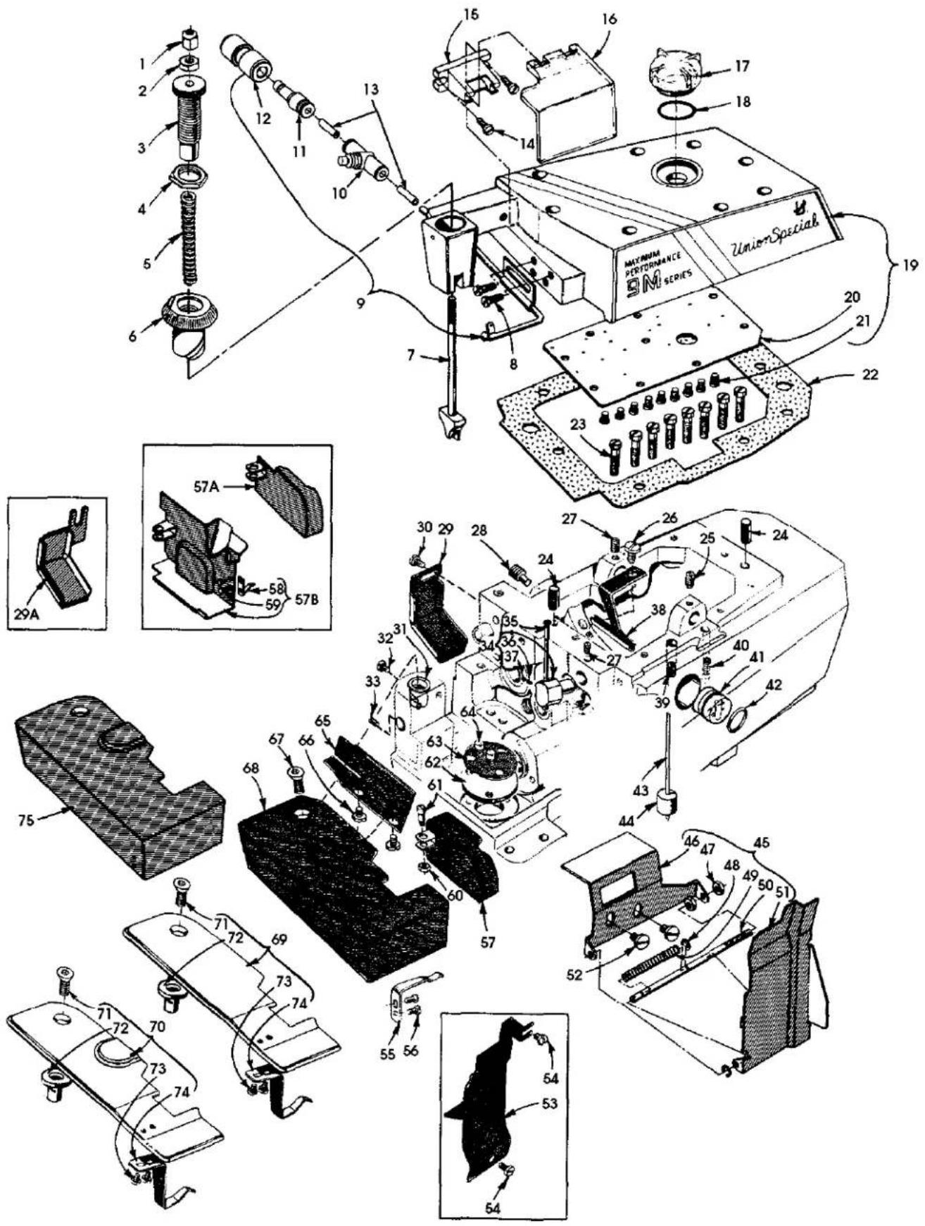
Technical diagram of a sewing machine with numbered parts and exploded views, including assembly lines and component labels.MAIN FRAME, PRESSER FOOT RELEASE PARTS, MISCELLANEOUS COVERS AND PLATES
| Ref. No. | Part No. | Description | Amt. Req. |
| 1 thru 44 | See preceding page | ||
| 45 | 39578 AX | Guard Assembly, chip, all Styles except XRC, XRN, XSD, CXRN, CXSD | 1 |
| 46 | 39578 AL | Base | 1 |
| 47 | 43443 Q | Nut | 2 |
| 48 | 660-210 | Ring, retaining | 2 |
| 49 | 39158 U | Spring | 1 |
| 50 | 39878 C | Pin, hinge | 1 |
| 51 | 39578 AY | Cover | 1 |
| 52 | 22569 D | Screw | 2 |
| 53 | 39578 T | Guard, chip, Styles XRN, XSD, CXRN, CXSD | 1 |
| - | 39578 U | Guard, chip, Style XRC | 1 |
| 54 | 22569 D | Screw | 2 |
| 55 | 39532 A | Spring, cloth plate latch, all Styles except XRN, XSD, CXRN, CXSD | 1 |
| 56 | 90 | Screw, latch spring, all Styles except XRN, XSD, CXRN, CXSD | 2 |
| 57 | 39582 D | Cover, feed mechanism, all Styles w/o Power "AIR-KLIPP" chain cutter except XQJ, XRN, XSD | 1 |
| - | 39582 K | Cover, feed mechanism, Style XQJ | 1 |
| 57A | 99679 | Cover, feed mechanism, Styles CXQA, CXQB, CXQJ, CXSQB | 1 |
| 57B | 39582 EA | Cover, feed mechanism, Styles XRN, XSD, CXRN, CXSD | 1 |
| 58 | 39582 H | Spring | 1 |
| 59 | 39582 J | Rivet | 2 |
| 60 | 41071 G | Nut | 1 |
| 61 | 86 X | Screw | 1 |
| 62 | 39594 H | Strainer, oil | 1 |
| 63 | 39594 G | Screen, oil filter | 1 |
| 64 | 22569 B | Screw | 2 |
| 65 | 39578 F | Guard, cloth plate fabric, Styles XQA, XQB, XQJ, XRB, XRC, XTA, XSQB | 1 |
| 66 | 138 | Screw, Styles XQA, XQB, XQJ, XRB, XRC, XTA, XSQB | 2 |
| 67 | 22657 D-12 | Screw, cloth plate, all Styles except XRN, XSD, CXRN, CXSD | 1 |
| 68 | 39501 D | Cloth Plate, Styles XQA, XQB, XRC-045, XTA, XSQB | 1 |
| 69 | 39501 DG | Cloth Plate, Style XQJ | 1 |
| - | 39501 DD | Cloth Plate, Style XRB | 1 |
| - | 39501 DC | Cloth Plate, Style XRC-060 | 1 |
| - | 39501 AP | Cloth Plate, Styles XRN, XSD | 1 |
| 70 | 39501 M | Cloth Plate, Styles CXRN, CXSD | 1 |
| 71 | 22657 D-12 | Screw, Styles XRN, XSD, CXRN, CXSD | 1 |
| 72 | 39501 K | Stud, Styles XRN, XSD, CXRN, CXSD | 1 |
| 73 | 22513 | Screw, Styles XRN, XSD, CXRN, CXSD | 2 |
| 74 | 39532 D | Spring, latch, Styles XRN, XSD, CXRN, CXSD | 1 |
| 75 | G39501 D | Cloth Plate, Styles CXQA, CXQB, CXQJ, CXSQB | 1 |
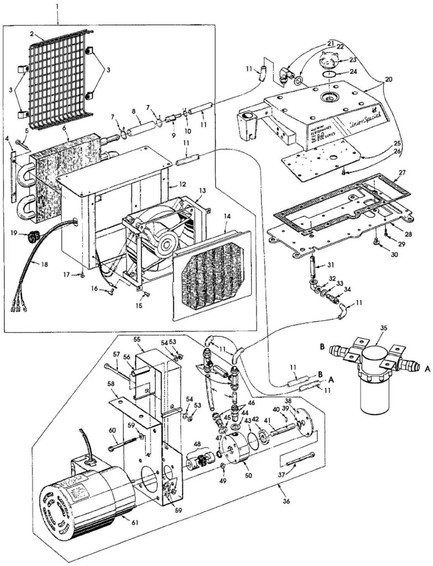
text_image
Technical diagram of an electric motor assembly with numbered components and labeled partsCRANKSHAFT MECHANISM AND BUSHINGS
| Ref.No. | PartNo. | Description | Amt.Req. |
| 1 | 22769 B | Screw ---- | 1 |
| 2 | 39521 D | Cap, pulley ---- | 1 |
| 3 | 39521 H | Pulley ---- | 1 |
| 4 | 22650 CD-4 | Screw ---- | 2 |
| 5 | 22569 X | Screw ---- | 3 |
| 6 | 39590 H | Plate, retaining, crankshaft ball bearing ---- | 1 |
| 7 | 660-835 | Bearing, ball ---- | 1 |
| 8 | 22569 Y | Screw ---- | 3 |
| 9 | 39590 Z | Housing, bearing ---- | 1 |
| 10 | 39590 AA | Plate, retaining, crankshaft ball bearing ---- | 1 |
| 11 | 39590 J | Washer, thrust ---- | 1 |
| 12 | 39542 | Pulley, crankshaft ---- | 1 |
| 13 | 22650 CB-4 | Screw, set ---- | 2 |
| 14 | 39590 Y | Bearing, crankshaft (intermediate) ---- | 1 |
| 15 | 660-443 | "0" Ring ---- | 1 |
| 16 | 660-764 | Seal, oil ---- | 1 |
| 17 | 22565 F | Screw ---- | 1 |
| 18 | 39590 D | Bearing, split ---- | 1 |
| 19 | 97 A | Screw ---- | 2 |
| 20 | 29477 MS | Crankshaft and Needle Driving Arm Crank Assembly ---- | 1 |
| 21 | 29477 MC | Needle Driving Arm Crank and Connecting Rod Assembly ---- | 1 |
| 22 | 22768 C | Screw, connecting rod pin ---- | 1 |
| 23 | 22596 H | Screw, driving arm crank ---- | 1 |
| 24 | 22587 M | Screw, connecting rod ---- | 2 |
| 25 | 51-228 Blk. | Plug, vent ---- | 1 |
| 26 | 39541 C | Key, feed driving eccentric ---- | 1 |
| 27 | 30-106 Blk. | Plug, wood ---- | 1 |
| 28 | 22781 A | Screw ---- | 1 |
| 29 | 39591 B | Counterweight, crankshaft (right) ---- | 1 |
| 30 | 22747 B | Screw ---- | 6 |
| 31 | 39590 N | Stud, split bearing ---- | 1 |
| 32 | 39591 A | Counterweight, crankshaft (intermediate) ---- | 1 |
| 33 | 39591 K | Counterweight, crankshaft (left) ---- | 1 |
| 34 | 87 C | Screw ---- | 1 |
| 35 | 39594 N | Splasher, oil ---- | 1 |
| 36 | 666-94 | Wick and Spring, oil ---- | 1 |
| 37 | 39590 AB | Bushing, crankshaft (left) ---- | 1 |
| 38 | 39590 T | Bushing, crankshaft (intermediate) ---- | 1 |
| 39 | 39544 X | Bushing, lower looper bar ---- | 1 |
| 40 | 39552 P | Bushing, needle driving arm crank (right) ---- | 1 |
| 41 | 39573 AA | Bushing, upper knife driving arm (right) ---- | 1 |
| 42 | 39555 R | Bushing, foot lifter shaft (right) ---- | 1 |
| 43 | 39555 P | Bushing, foot lifter shaft (left) ---- | 1 |
| 44 | 39573 K | Bushing, upper knife driving arm (left) ---- | 1 |
| 45 | 39552 U | Bushing, needle driving arm crank (left) ---- | 1 |

text_image
Technical diagram of mechanical assembly with numbered parts and exploded view, including labeled parts 1 through 7B.NEEDLE DRIVE AND FEED MECHANISM
(ALL STYLES EXCEPT 39500 XQJ AND CXQJ)
| Ref.No. | PartNo. | Description | Amt.Req. |
| 1 | 39535 C | Pin, feed adjusting | 1 |
| 2 | 22565 F | Screw, locking | 1 |
| 3 | 39578 P | Bracket, fabric guard mounting, all Styles w/o Power "AIR-KLIPP" chain cutter | 1 |
| 4 | 22569 B | Screw, all Styles w/o Power "AIR-KLIPP" chain cutter | 2 |
| 5 | 8372 A | Washer, all Styles w/o Power "AIR-KLIPP" chain cutter | 2 |
| 6 | 87 | Screw, all Styles w/o Power "AIR-KLIPP" chain cutter | 2 |
| 7 | G39578 M | Guard, fabric, all Styles w/o Power "AIR-KLIPP" chain cutter except XRN | 1 |
| 7A | 39578 V | Guard, fabric, Style XRN | 1 |
| 7B | 39556 N | Lever, tilt, presser foot, Style XRN | 1 |
| 7C | 22561 | Screw, presser foot tilt lever, Style XRN | 2 |
| 8 | 22541 B | Screw | 2 |
| 9 | 39835 G | Washer, plate | 1 |
| 10 | 39535 W | Guide, main feed bar (left) | 1 |
| 11 | 39534 | Feed Bar, main | 1 |
| 12 | 39535 V | Block, feed bar guide | 1 |
| 13 | 22797 A | Screw, chaining feed dog, all Styles except XRB, XTA | 1 |
| 14 | Feed Dog, chaining (See Pages 49 & 51) | 1 | |
| 15 | 39534 G | Feed Bar, differential | 1 |
| 16 | 39535 D | Guide, differential feed bar (right) | 1 |
| 17 | 22569 B | Screw | 2 |
| 18 | 53634 C | Washer | 2 |
| 19 | 39536 CV | Stud, differential, feed bar driving | 1 |
| 20 | 22569 G | Screw | 3 |
| 21 | 39534 AF | Washer, thrust, differential feed bar | 1 |
| 22 | 39538 A | Block, feed lift | 1 |
| 23 | Feed Dog, differential (See Pages 49 & 51) | 1 | |
| 24 | 22528 | Screw, differential feed dog | 1 |
| 25 | 39536 CX | Stud, main feed bar driving | 1 |
| 26 | Feed Dog, main (See Pages 49 & 51) | 1 | |
| 27 | 93 A | Screw, main feed dog, all Styles except XRN, CXRN | 1 |
| - | 22528 | Screw, main feed dog, Styles XRN, CXRN | 1 |
| 28 | 39540 M-7 | Eccentric, differential feed driving, Styles XRN, CXRN | 1 |
| - | 39540 M-8 | Eccentric, differential feed driving, Styles XSD, CXSD | 1 |
| - | 39540 M-10 | Eccentric, differential feed driving, Styles XQA, XQB, CXQA, CXQB, XSQB, CXSQB | 1 |
| - | 39540 M-18 | Eccentric, differential feed driving, Styles XRB, XRC | 1 |
| - | 39540 M-30 | Eccentric, differential feed driving, Style XTA | 1 |
| 29 | 39536 CW | Bushing, differential feed bar driving stud | 1 |
| 30 | 39536 E | Nut, feed bar driving stud | 2 |
| 31 | 39536 CY | Bushing, main feed bar driving stud | 1 |
| 32 | 22781 A | Screw, crankshaft | 1 |
| 33 | 39543 AA | Spacer, crankshaft | 1 |
| 34 | 39536 CT | Connection, main feed bar driving | 1 |
| 35 thru 62 | See following page |

text_image
Technical diagram of mechanical assembly with numbered parts and exploded view, including labeled parts like 7A, 7B, and 51-59.NEEDLE DRIVE AND FEED MECHANISM
(ALL STYLES EXCEPT 39500 XQJ AND CXQJ)
| Ref. No. | Part No. | Description | Amt. Req. |
| 1 thru 34 | See preceding page | ||
| 35 | 39540 M-9 | Eccentric, main feed driving, Styles XRN, CXRN ---- | 1 |
| - | 39540 M-12 | Eccentric, main feed driving, Styles XQA, XQB, CXQA,CXQB, XSQB, CXSQB ---- | 1 |
| - | 39540 M-14 | Eccentric, main feed driving, Styles XSD, CXSD ---- | 1 |
| - | 39540 M-20 | Eccentric, main feed driving, Styles XRB, XRC ---- | 1 |
| - | 39540 M-30 | Eccentric, main feed driving, Style XTA ---- | 1 |
| 36 | 39536 CU | Connection, differential feed bar driving ---- | 1 |
| 37 | 14077 A | Nut, needle clamp stud ---- | 1 |
| 38 | 39551 H | Washer, needle clamp ---- | 1 |
| 39 | 154 GAS | Needle, all Styles except XRB, XRC, XSQB, CXSQB ---- | 1 |
| - | 162 SAS | Needle, Styles XSQB, CXSQB ---- | 1 |
| 40 | 39552 Z | Arm, needle driving, marked "K", all Styles exceptXRB, XRC, XSQB, CXSQB ---- | 1 |
| - | 39552 AJ | Arm, needle driving, marked "S", Styles XSQB, CXSQB ---- | 1 |
| 41 | 39552 AD | Pin, stop ---- | 1 |
| 42 | 22596 E | Screw ---- | 1 |
| 43 | 39551 J | Stud, needle clamp ---- | 4 |
| 44 | 39568 AH | Pull-off, looper thread ---- | 1 |
| 45 | 39568 AC | Lever, looper thread pull-off ---- | 1 |
| 46 | 88 B | Screw ---- | 2 |
| 47 | 39552 AG | Seal, oil, needle driving shaft ---- | 1 |
| 48 | 660-207 | Ring, oil seal ---- | 1 |
| 49 | 39543 Y | Collar, thrust, needle drive shaft ---- | 1 |
| 50 | 22782 A | Screw ---- | 1 |
| 51 | 39594 N | Splasher, oil ---- | 1 |
| 52 | 87 C | Screw ---- | 1 |
| 53 | 39552 R | Shaft, needle driving ---- | 1 |
| 54 | C50043 F | Washer, for thrust collar ---- | 1 |
| 55 | 22513 D | Screw ---- | 1 |
| 56 | 87 C | Screw ---- | 1 |
| 57 | 39563 AC | Cam Pull-off, needle thread, all Styles except XRB ---- | 1 |
| 58 | 154 GDS | Needle, Style XRC-060 ---- | 2 |
| - | 154 GFS | Needle, Styles XRB, XRC-045 ---- | 2 |
| 59 | 39552 AA | Arm, needle driving, marked "L", Styles XRB, XRC-045 ---- | 1 |
| - | 39552 AB | Arm, needle driving, marked "M", Style XRC-060 ---- | 1 |
| 60 | 22596 E | Screw ---- | 1 |
| 61 | 39552 AD | Pin, stop ---- | 1 |
| 62 | 39563 P | Pull-off, needle thread, Style XRB ---- | 1 |
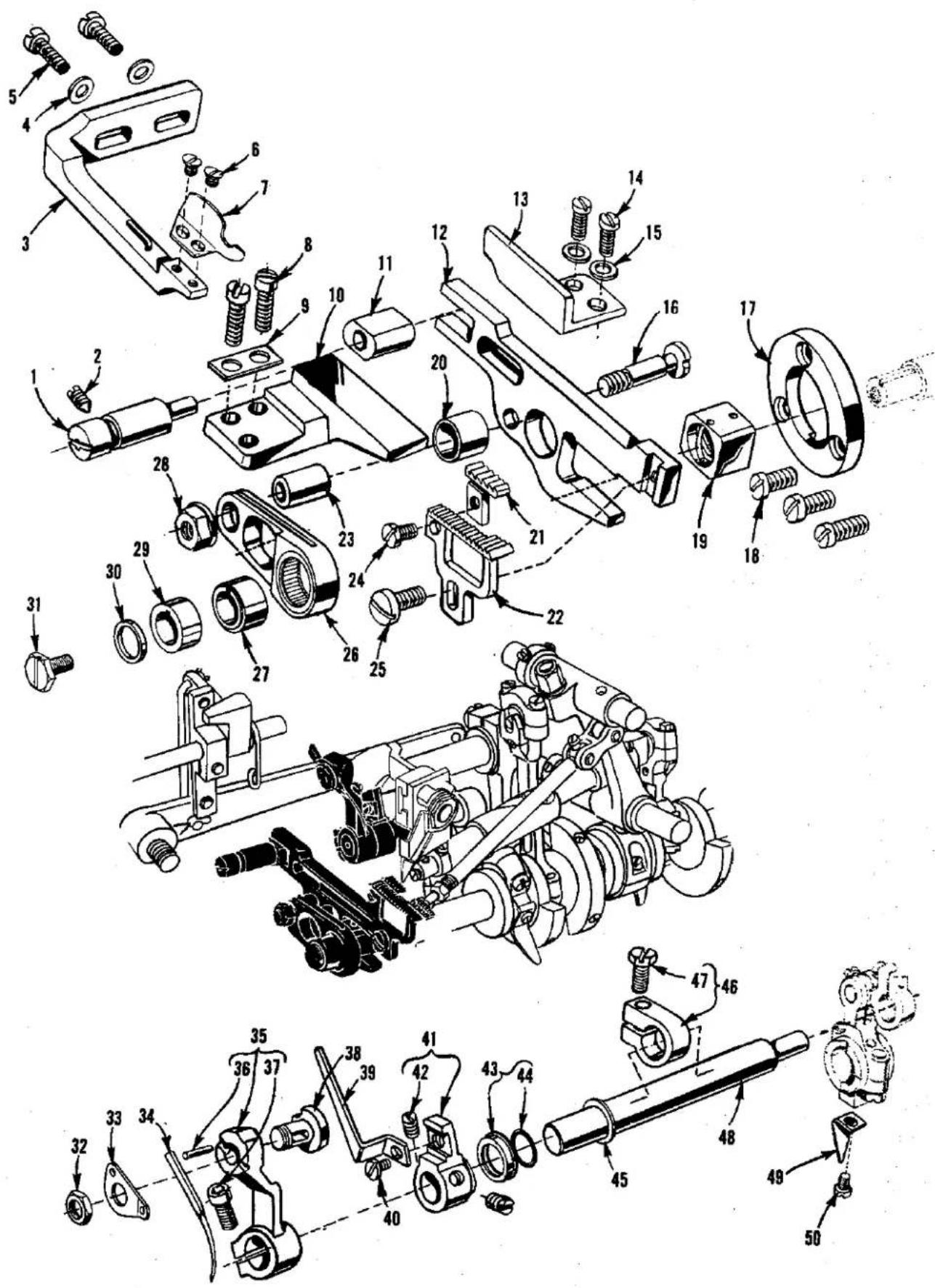
text_image
Technical diagram of mechanical assembly with numbered parts for identification and assembly reference.NEEDLE DRIVE AND PLAIN FEED MECHANISM (STYLES 39500 XQJ, CXQJ, UNLESS OTHERWISE SPECIFIED)
| Ref. No. | Part No. | Description | Amt. Req. |
| 1 | 39535 C | Pin, feed adjusting | 1 |
| 2 | 22565 F | Screw, locking | 1 |
| 3 | 39578 P | Bracket, fabric guard mounting, Style XQJ | 1 |
| 4 | 8372 A | Washer, Style XQJ | 2 |
| 5 | 22569 B | Screw, Style XQJ | 2 |
| 6 | 87 | Screw, Style XQJ | 2 |
| 7 | G39578 M | Guard, fabric, Style XQJ | 1 |
| 8 | 22541 B | Screw | 2 |
| 9 | 39835 G | Washer, plate | 1 |
| 10 | 39535 F | Guide, feed bar (left) | 1 |
| 11 | 39535 V | Block, feed bar guide | 1 |
| 12 | 39534 G | Feed Bar | 1 |
| 13 | 39535 D | Guide, feed bar (right) | 1 |
| 14 | 22569 B | Screw | 2 |
| 15 | 53634 C | Washer | 2 |
| 16 | 39536 CV | Stud, feed bar driving | 1 |
| 17 | 39534 AF | Washer, thrust, feed bar | 1 |
| 18 | 22569 G | Screw | 3 |
| 19 | 39538 A | Block, feed lift | 1 |
| 20 | 39536 D | Spacer, feed bar | 1 |
| 21 | 39505 K | Feed Dog, chaining | 1 |
| 22 | 39505 J | Feed Dog, main | 1 |
| 23 | 39536 CY | Bushing, feed bar driving stud | 1 |
| 24 | 22768 B | Screw, chaining feed dog | 1 |
| 25 | 22528 | Screw, main feed dog | 1 |
| 26 | 39536 CU | Connection, feed bar driving | 1 |
| 27 | 39540 M-5 1/2 | Eccentric, main feed driving | 1 |
| 28 | 39536 E | Nut, feed bar driving stud | 1 |
| 29 | 39540 R | Spacer, feed drive eccentric | 1 |
| 30 | 39543 AA | Spacer, crankshaft | 1 |
| 31 | 22781 A | Screw, crankshaft | 1 |
| 32 | 14077 A | Nut, needle clamp stud | 1 |
| 33 | 39563 AA | Washer, needle clamp and needle thread pull-off eyelet | 1 |
| 34 | 154 GAS | Needle | 1 |
| 35 | 39552 Z | Arm, needle driving, marked "K" | 1 |
| 36 | 39552 AD | Pin, stop | 1 |
| 37 | 22596 E | Screw | 1 |
| 38 | 39551 J | Stud, needle clamp | 1 |
| 39 | 39568 AH | Pull-off, looper thread | 1 |
| 40 | 22513 D | Screw | 1 |
| 41 | 39568 AC | Lever, looper thread pull-off | 1 |
| 42 | 88 B | Screw | 2 |
| 43 | 39552 AG | Seal, oil, needle driving shaft | 1 |
| 44 | 660-207 | Ring, oil seal | 1 |
| 45 | C50043 F | Washer, for thrust collar | 1 |
| 46 | 39543 Y | Collar, thrust, needle driving shaft | 1 |
| 47 | 22782 A | Screw | 1 |
| 48 | 39552 R | Shaft, needle driving | 1 |
| 49 | 39594 N | Splasher, oil | 1 |
| 50 | 87 C | Screw | 1 |
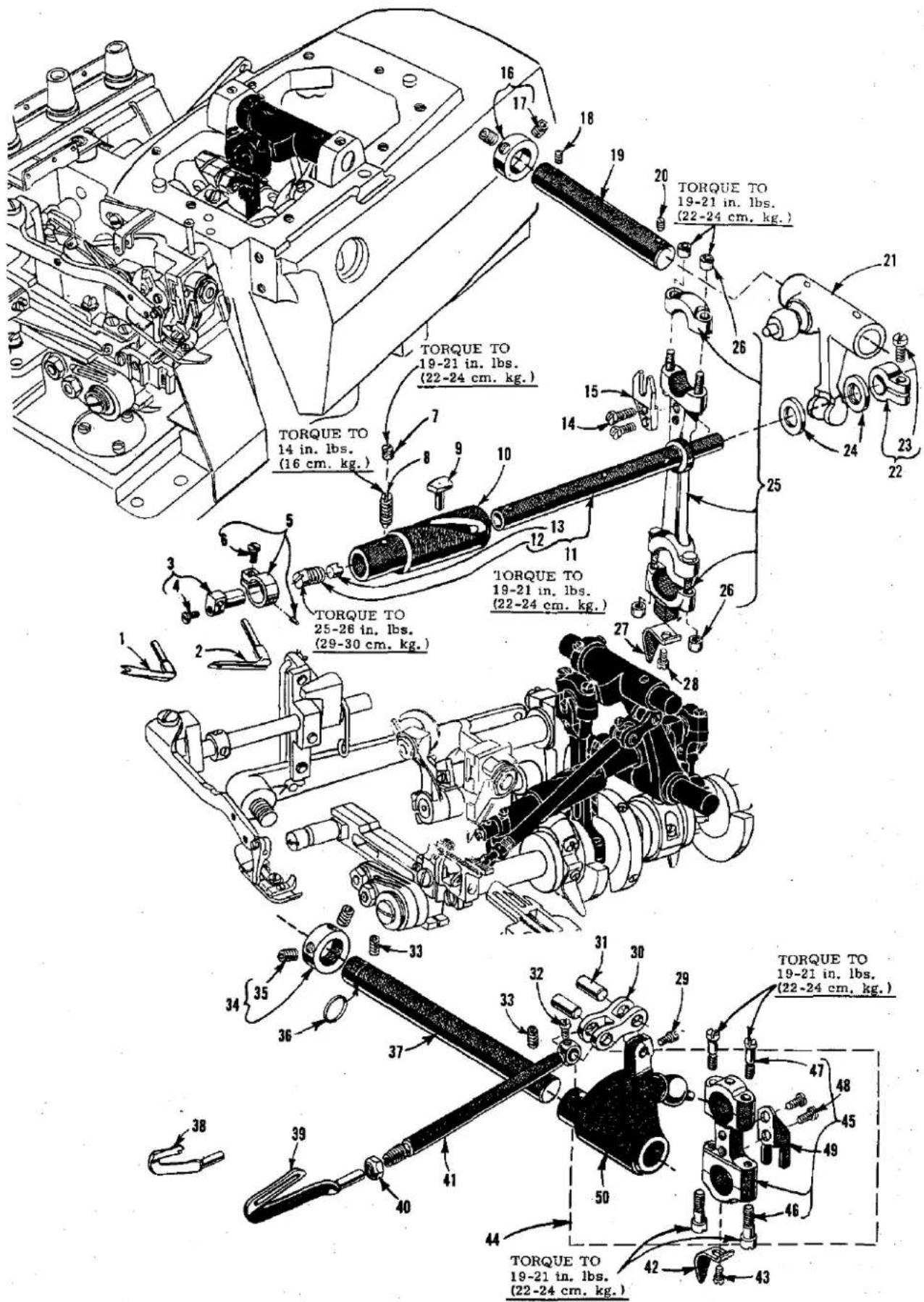
text_image
TORQUE TO 19-21 in. lbs. (22-24 cm. kg.) TORQUE TO 19-21 in. lbs. (22-24 cm. kg.) TORQUE TO 14 in. lbs. (16 cm. kg.) TORQUE TO 25-26 in. lbs. (29-30 cm. kg.) TORQUE TO 19-21 in. lbs. (22-24 cm. kg.) TORQUE TO 19-21 in. lbs. (22-24 cm. kg.) TORQUE TO 19-21 in. lbs. (22-24 cm. kg.) TORQUE TO 19-21 in. lbs. (22-24 cm. kg.)UPPER AND LOWER LOOPER/SPREADER DRIVING PARTS
| Ref.No. | PartsNo. | Description | Amt.Req. |
| 1 | 39560 A | Spreader, upper, Styles XOJ, XRC-060, XSD, CXOJ, CXSD ---- | 1 |
| 2 | 39508 A | Looper, upper, marked "CC", all Styles except XOJ, XRC-060XSD, CXOJ, CXSD ---- | 1 |
| 3 | 39843 H | Holder, upper looper/spreader ---- | 1 |
| 4 | 22768 B | Screw ---- | 1 |
| 5 | 39743 | Clamp, upper looper/spreader holder ---- | 1 |
| 6 | 22768 B | Screw ---- | 1 |
| 7 | 1025 L | Screw, locking ---- | 1 |
| 8 | 22565 H | Screw, spot, bushing and cam guide ---- | 1 |
| * 9 | 39543 T | Follower, cam ---- | 1 |
| *10 | 39543 S | Bushing and Cam Guide ---- | 1 |
| *11 | 39543 Z | Shaft, upper looper/spreader drive ---- | 1 |
| 12 | 22503 F | Screw, cam follower locking clamp ---- | 1 |
| 13 | 39543 E | Clamp, cam follower locking ---- | 1 |
| 14 | 97 | Screw ---- | 2 |
| 15 | 39544 J | Fork, ball joint guide ---- | 1 |
| 16 | 482 C | Collar, upper looper/spreader shaft ---- | 1 |
| 17 | 22894 C | Screw, set ---- | 2 |
| 18 | 22565 | Screw, set ---- | 1 |
| 19 | 39543 X | Shaft, upper looper/spreader drive lever ---- | 1 |
| 20 | 22565 S | Screw, spot ---- | 1 |
| 21 | 39543 W | Lever, upper looper/spreader drive ---- | 1 |
| 22 | 39543 M | Collar, clamp ---- | 1 |
| 23 | 22562 A | Screw ---- | 1 |
| 24 | 39543 P | Washer, thrust ---- | 2 |
| 25 | 39543 AC | Connecting Rod ---- | 1 |
| 26 | 39543 AF | Nut, barrel ---- | 4 |
| 27 | 39594 N | Splasher, oil ---- | 1 |
| 28 | 87 C | Screw ---- | 1 |
| 29 | 77 | Screw ---- | 1 |
| 30 | 39544 B | Link, lower looper bar connecting ---- | 1 |
| 31 | 39544 D | Pin, connecting link ---- | 2 |
| 32 | 77 | Screw ---- | 1 |
| 33 | 22894 AE | Screw, set ---- | 2 |
| 34 | 482 C | Collar, lower looper driving shaft ---- | 1 |
| 35 | 22894 C | Screw, set ---- | 2 |
| 36 | 660-206 | "0" Ring ---- | 1 |
| 37 | 39544 V | Shaft, lower looper driving ---- | 1 |
| 38 | 39560 B | Spreader, lower, Styles XRB, XRC-045, XRN, CXRN ---- | 1 |
| 39 | 39508 B | Looper, lower, all Styles except XRB, XRC-045, XRN,CXRN ---- | 1 |
| 40 | 39151 | Nut ---- | 1 |
| 41 | 39544 | Bar, lower looper ---- | 1 |
| 42 | 39594 N | Splasher, oil ---- | 1 |
| 43 | 87 C | Screw ---- | 1 |
| 44 | 29126 DF | Looper Bar Driving Lever and Connecting Rod Assembly,lower ---- | 1 |
| 45 | 39544 N | Connecting Rod ---- | 1 |
| 46 | 22729 E | Screw ---- | 2 |
| 47 | 22729 D | Screw ---- | 2 |
| 48 | 97 | Screw ---- | 2 |
| 49 | 39544 S | Fork, guide ---- | 1 |
| 50 | 39544 U | Lever, lower looper bar driving ---- | 1 |
*Assembly No. 29126 EP is recommended for replacement instead of individual parts.
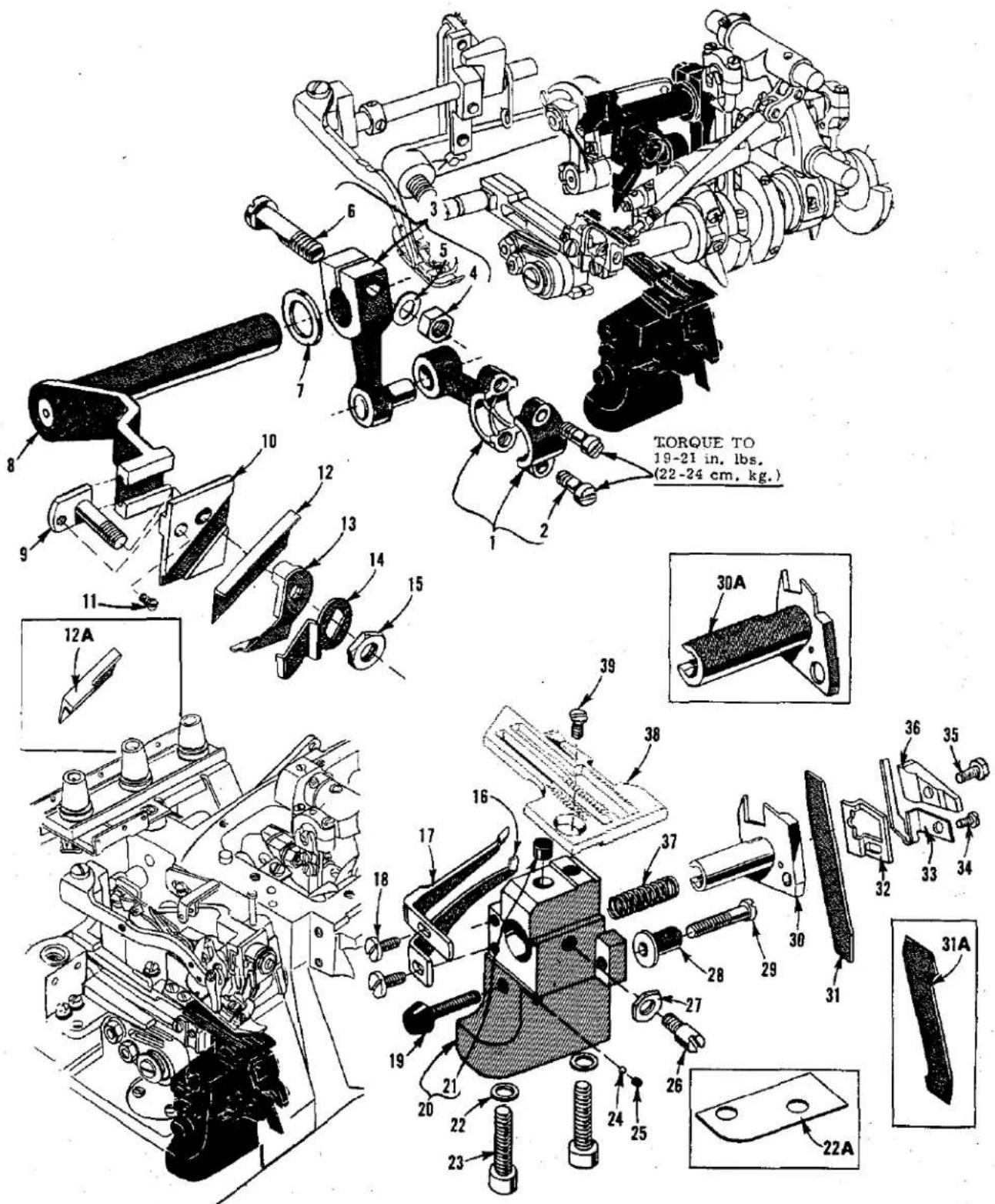
text_image
TORQUE TO 19-21 in. lbs. (22-24 cm. kg.) 30A 36 35 33 34 32 31 31A 22AUPPER AND LOWER KNIFE MECHANISM
| Ref.No. | PartNo. | Description | Amt.Req. |
| 1 | 39573 J | Connecting Rod, upper knife driving | 1 |
| 2 | 22587 J | Screw | 2 |
| 3 | 39573 E | Lever, upper knife driving | 1 |
| 4 | 55235 E | Nut | 1 |
| 5 | 6042 A | Washer | 1 |
| 6 | 55235 D | Stud, locking | 1 |
| 7 | 39573 A | Washer, upper knife driving arm | 1 |
| 8 | 39573 H | Arm, upper knife driving | 1 |
| 9 | 39571 D | Stud, clamp, all Styles except XQJ, CXQJ | 1 |
| - | 39571 C | Stud, clamp, Styles XQJ, CXQJ | 1 |
| 10 | 39572 | Block, upper knife holder, Styles XQA, XQB, CXQA, CXQB,XSQB, CXSQB | 1 |
| - | 39772 | Block, upper knife holder, Styles XRB, XRC, XRN, XSD, XTA,CXRN, CXSD | 1 |
| - | 39872 | Block, upper knife holder, Styles XQJ, CXQJ | 1 |
| 11 | 22738 | Screw, clamp stud | 1 |
| 12 | 39570 C | Knife, upper, all Styles except XQJ, CXQJ | 1 |
| 12A | 39570 CJ | Knife, upper, Styles XQJ, CXQJ | 1 |
| 13 | 39571 F | Clamp, upper knife | 1 |
| 14 | 39571 B | Guard, chain | 1 |
| 15 | 14077 | Nut, clamp stud | 1 |
| 16 | 39525 R | Guard, needle, front, Styles XQA, XQB, XTA, CXQA, CXQB,XSQB, CXSQB | 1 |
| - | 39525 H | Guard, needle, front, Styles XRB, XRC-045 | 1 |
| - | 39525 L | Guard, needle, front, Styles XQJ, XRC-060, CXQJ | 1 |
| 17 | GA39525 N | Guard, needle, rear, all Styles except XRB, XRC, XRN, XSD,CXRN, CXSD | 1 |
| - | 39525 J | Guard, needle rear, Styles XRB, XRC | 1 |
| 18 | 22585 A | Screw, needle guard, all Styles except XRN, XSD, CXRN, CXSD | 2 |
| 19 | GR-660-824 | Bumper, cloth plate, all Styles except XRN, XSD, CXRN, CXSD | 1 |
| 20 | 39580 A | Bracket, throat plate and lower knife support, all Stylesexcept XQJ, XRN, XSD, CXQJ, CXRN, CXSD | 1 |
| - | 39580 AE | Bracket, throat plate and lower knife support, Styles XQJ, CXQJ | 1 |
| 21 | 39880 N | Bumper, rubber, cloth plate isolation | 1 |
| 22 | 39580 F | Washer | 2 |
| 22A | 39580 E | Shim, Styles XQJ, CXQJ | 1 |
| 23 | 22653 B-12 | Screw | 2 |
| 24 | 660-459 | Ball, nylon | 1 |
| 25 | 78 | Screw, set | 1 |
| 26 | 22892 B | Screw, locking, lower knife holder, all Styles except XRN,XSD, CXRN, CXSD | 1 |
| 27 | 14077 | Nut, locking screw, all Styles except XRN, XSD, CXRN, CXSD | 1 |
| 28 | 39550 C | Stud, locating | 1 |
| 29 | 22729 B | Screw, locating stud, all Styles except XRN, XSD, CXRN, CXSD | 1 |
| 30 | 39550 AF | Holder, lower knife, all Styles except XQJ, XRN, XSD, CXQJ,CXRN, CXSD | 1 |
| 30A | 39550 AB | Holder, lower knife, Styles XQJ, CXQJ | 1 |
| 31 | 39549 C | Knife, lower, all Styles except XQJ, CXQJ | 1 |
| 31A | 39549 CJ | Knife, lower, Styles XQJ, CXQJ | 1 |
| 32 | 39550 AC | Plate, lower knife guide, all Styles except XRN, XSD, CXRN, CXSD - | 1 |
| 33 | 39550 AE | Spring, lower knife clamp, all Styles except XRN, XSD, CXRN, CXSD- | 1 |
| 34 | 605 A | Screw, lower knife clamp spring, all Styles except XRN, XSD,CXRN, CXSD | 1 |
| 35 | 22588 J | Screw, lower knife clamp | 1 |
| 36 | 39550 AD | Clamp, lower knife, all Styles except XRN, XSD, CXRN, CXSD | 1 |
| 37 | 39550 E | Spring, lower knife holder | 1 |
| 38 | Throat plate, (See pages 49 & 51) | 1 | |
| 39 | 22524 | Screw, throat plate | 1 |
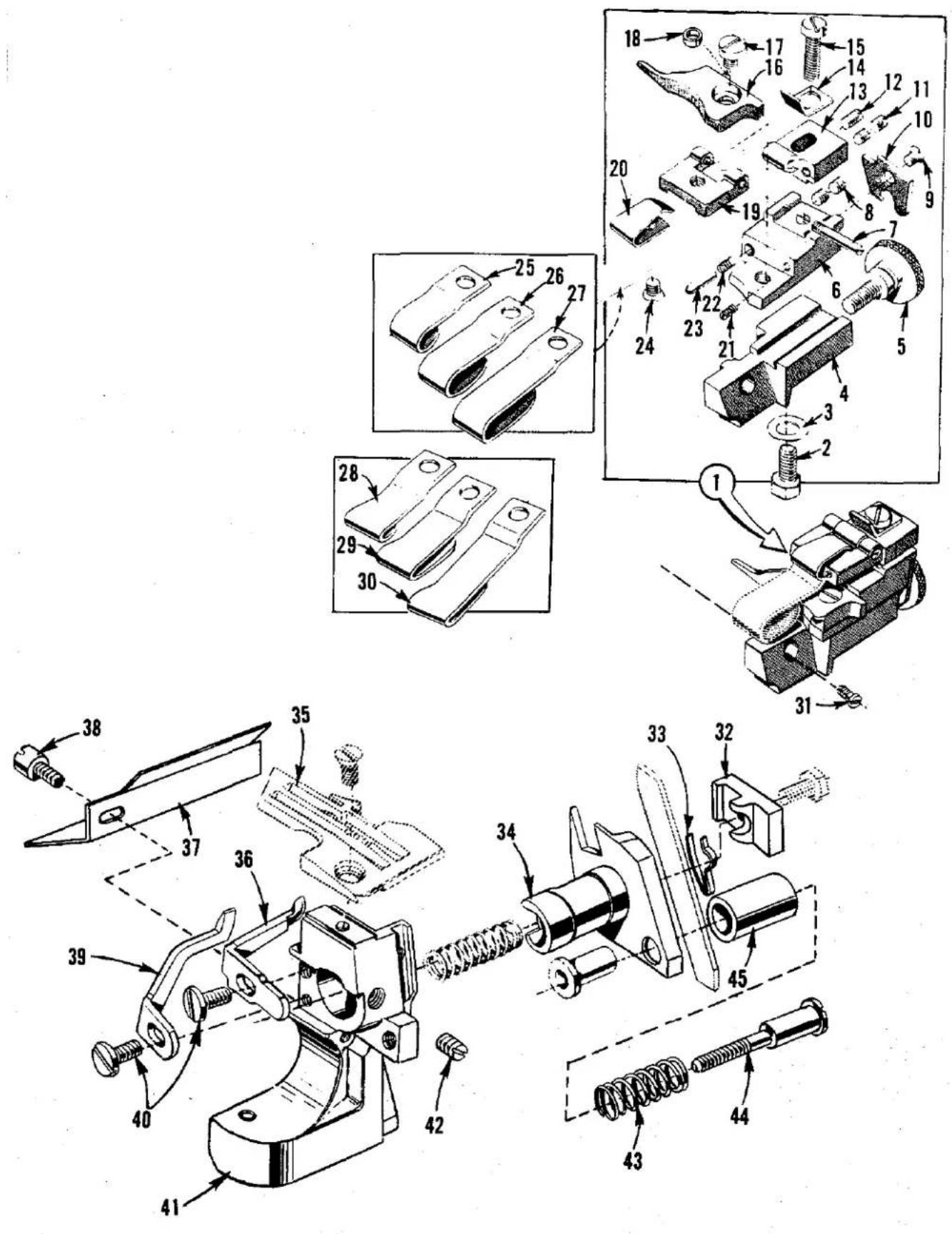
text_image
Technical diagram of mechanical assembly with numbered parts and exploded views, likely from an engineering manual.HEMMER GUIDE ASSEMBLY AND LOWER KNIFE PARTS (STYLES XRN, XSD, CXRN, CXSD)
| Ref.No. | PartNo. | Description | Amt.Req. |
| 1 | 29481 L | Hemmer Guide Assembly | 1 |
| 2 | 303 | Screw, edge guide support | 1 |
| 3 | 61303 D | Washer, cup | 1 |
| 4 | 39589 AC | Base, hemming attachment | 1 |
| 5 | 22873 C | Screw, adjusting, edge guide support | 1 |
| 6 | 39589 AD | Support, edge guide | 1 |
| 7 | 22799 B | Screw, hinge, overhanging guide hinge block | 1 |
| 8 | 22743 | Screw, edge guide tension spring | 2 |
| 9 | 222 D | Screw, hemmer guide end plate | 1 |
| 10 | 39589 AF | Plate, hemmer guide end | 1 |
| 11 | HA73 B | Screw, stop, overhanging guide hinge block | 2 |
| 12 | 73 C | Screw, set, hemmer guide stop screw | 1 |
| 13 | 39589 AB | Block, hinge | 1 |
| 14 | 39589 AJ | Stop, hemmer guide | 1 |
| 15 | 22729 A | Screw, hemmer guide stop | 1 |
| 16 | 39503 L | Guide, edge | 1 |
| 17 | 22513 C | Screw, edge guide | 1 |
| 18 | 39589 AG | Sleeve, edge guide | 1 |
| 19 | 39589 AA | Block, hinge, overhanging guide | 1 |
| 20 | 39589 AH | Spring, holding | 1 |
| 21 | 79077 | Screw, stop, edge guide | 1 |
| 22 | 39568 J | Spring, edge guide tension | 1 |
| 23 | 39589 AL | Pin, edge guide tension spring | 1 |
| 24 | 222 D | Screw, overhanging guide | 1 |
| 25 | 39589 AK-1/2 | Overhanging Guide, for 1/2 inch (12.7mm) hem, Styles XSD, CXSD | 1 |
| 26 | 39589 AK-3/4 | Overhanging Guide, for 3/4 inch (19.0mm) hem, Styles XSD, CXSD | 1 |
| 27 | 39589 AK-1 | Overhanging Guide, for 1 inch (25.4mm) hem, Styles XSD, CXSD | 1 |
| 28 | 39589 AE-1/2 | Overhanging Guide, for 1/2 inch (12.7mm) hem, Styles XRN, CXRN | 1 |
| 29 | 39589 AE-3/4 | Overhanging Guide, for 3/4 inch (19.0mm) hem, Styles XRN, CXRN | 1 |
| 30 | 39589 AE-1 | Overhanging Guide, for 1 inch (25.4mm) hem, Styles XRN, CXRN | 1 |
| 31 | 22593 | Screw, hemming guide assembly | 1 |
| 32 | 39550 Z | Clamp, lower knife | 1 |
| 33 | 39550 M | Spring, lower knife clamp | 1 |
| 34 | 39550 T | Holder, lower knife | 1 |
| 35 | Throat Plate (See pages 49 & 51) | 1 | |
| 36 | 39525 K | Guard, needle, rear, Styles XRN, CXRN | 1 |
| - | 39525 E | Guard, needle, rear, Styles XSD, CXSD | 1 |
| 37 | 39582 BS | Shield, oil | 1 |
| 38 | 22585 G | Screw, oil shield and locking side cover | 1 |
| 39 | 39525 D | Guard, needle, front | 1 |
| 40 | 90 | Screw, needle guards | 2 |
| 41 | 39580 BA | Bracket, throat plate and lower knife support | 1 |
| 42 | 88 B | Screw, lower knife holder | 1 |
| 43 | 39550 J | Spring, knife pressure equalizing | 1 |
| 44 | 22559 H | Screw, adjusting | 1 |
| 45 | 39550 K | Cover, spring | 1 |
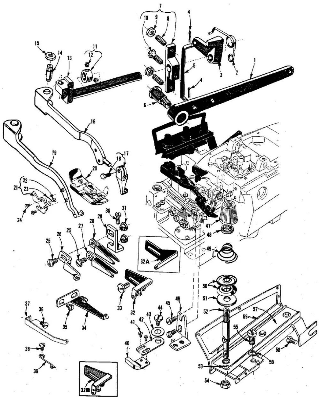
text_image
Exploded view diagram of a mechanical assembly with numbered parts and exploded viewsTHREAD TENSIONS, FOOT LIFTER PARTS AND MISCELLANEOUS EYELETS
| Ref.No. | PartNo. | Description | Amt.Rec. |
| 1 | 39855 | Lever, foot lifter ---- | 1 |
| 2 | 39555 B | Spring, foot lifter lever ---- | 1 |
| 3 | 39555 D | Lever, intermediate, foot lever ---- | 1 |
| 4 | 660-142 | Pin, cotter ---- | 2 |
| 5 | 39555 F | Link, lifter lever connecting ---- | 1 |
| 6 | 22566 B | Screw, lifter lever ---- | 1 |
| 7 | 39555 C | Arm, lifter lever ---- | 1 |
| 8 | 22597 E | Screw, set ---- | 2 |
| 9 | 12538 | Nut, lock ---- | 2 |
| 10 | 627 | Screw ---- | 1 |
| 11 | 12865 | Collar, thrust ---- | 1 |
| 12 | 88 | Screw ---- | 2 |
| 13 | 39555 AA | Shaft, foot lifter lever ---- | 1 |
| 14 | 22791 H | Pin, screw ---- | 1 |
| 15 | 258 A | Nut ---- | 1 |
| 16 | 39556 T | Arm, presser, all Styles except XQJ, XRB, XRC, CXQJ ---- | 1 |
| 17 | 39530 AH | Shank, presser foot, all Styles except XQJ, XRB, XRC, CXQJ ---- | 1 |
| 18 | 22781 | Screw ---- | 1 |
| 19 | 39556 D | Arm, presser, Styles XQJ, CXQJ ---- | 1 |
| - | 39556 J | Arm, presser, Styles XRB, XRC ---- | 1 |
| 20 | Presser Foot (See pages 49 & 51) ---- | 1 | |
| 21 | 39556 M | Knife, chain cutting, Styles XQJ, XRN, XSD, CXQJ, CXRN, CXSD ---- | 1 |
| 22 | 2273B G | Screw ---- | 1 |
| 23 | 39556 L | Blade, chain cutter ---- | 1 |
| 24 | 605 | Screw, chain cutting knife, Styles XQJ, XRN, XSD, CXQJ, CXRN, CXSD ---- | 2 |
| 25 | 376 A | Screw, looper thread eyelets, all Styles except XQJ, XRC-060, XSD, CXQJ, CXSD ---- | 2 |
| - | 376 A | Screw, looper thread eyelet, Styles XQJ, XRC-060, XSD, CXQJ, CXSD ---- | 1 |
| 26 | 39568 E | Eyelet, auxiliary looper thread, all Styles except XQJ, XRC-060, XSD, CXQJ, CXSD ---- | 1 |
| 27 | 39568 B | Eyelet, lower looper thread, all Styles except XQJ, XRB, XRC-045, XRN, CXQJ, CXRN ---- | 1 |
| - | 39568 L | Eyelet, lower looper thread, Styles XQJ, CXQJ ---- | 1 |
| - | 39568 B | Eyelet, upper looper thread, Styles XRB, XRN, XRC-045, CXRN ---- | 1 |
| 28 | 39568 L | Eyelet, upper looper thread, Styles XQA, XQB, XTA, CXQA, CXQB, XSQB, CXSQB ---- | 1 |
| 29 | 39568 D | Bracket, looper thread eyelet mounting ---- | 1 |
| 30 | 22569 B | Screw, looper thread eyelet mounting bracket ---- | 1 |
| 31 | 43139 A | Nut, looper thread eyelet screw, all Styles except XQJ, XRC-060, XSD, CXQJ, CXSD ---- | 2 |
| - | 43139 A | Nut, looper thread eyelet screw, Styles XQJ, XRC-060, XSD, CXQJ, CXSD ---- | 1 |
| 32 | 39563 H | Eyelet, needle thread, all Styles except XQJ, XRB CXQJ ---- | 1 |
| 32A | 39563 D | Eyelet, needle thread, Styles XQJ, CXQJ ---- | 1 |
| 32B | 39563 N | Eyelet, needle thread, Style XRB ---- | 1 |
| 33 | 22569 D | Screw, needle thread eyelet ---- | 1 |
| 34 | 39568 W | Guide, frame thread, Style XQJ ---- | 1 |
| 35 | 73 X | Screw, Style XQJ ---- | 2 |
| 36 | 22569 B | Screw, Style CXQJ ---- | 1 |
| 37 | 99664 A | Guide, frame thread, Style CXQJ ---- | 1 |
| 38 | 22726 A | Screw, all Styles except XQJ, CXQJ ---- | 1 |
| 39 | 39868 H | Eyelet, lower looper thread, Styles XQA, XQB, XRB, XRC, XRN, XSD, XTA, XSQB ---- | 1 |
| - | 53658 A | Eyelet, lower looper thread, Styles CXQA, CXQB, CXRN, CXSD, CXSQB ---- | 1 |
| 40 | 39503 A | Guide, edge, Styles XQJ, CXQJ ---- | 1 |
| 41 | 604 | Screw, Styles XQJ, CXQJ ---- | 2 |
| 42 | 39503 D | Arm, edge guide swinging, Styles XQJ, CXQJ ---- | 1 |
| 43 | 12957 E | Washer, spring, Styles XQJ, CXQJ ---- | 1 |
| 44 | 22758 E | Screw, swinging arm, Styles XQJ, CXQJ ---- | 1 |
| 45 | 22569 C | Screw, edge guide mounting bracket, Styles XQJ, CXQJ ---- | 2 |
| 46 | 39503 C | Bracket, edge guide mounting, Styles XQJ, CXQJ ---- | 1 |
| 47 | 39592 AA | Nut (green) needle tension ---- | 1 |
| - | 39592 AB | Nut (blue) upper looper tension, all Styles except XQJ, XRC, XSD, CXQJ, CXSD ---- | 1 |
| - | 39592 AC | Nut (red) lower looper tension, all Styles except XRB, XRN, CXRN ---- | 1 |
| - | 39592 Z | Nut (yellow) needle tension, Styles XRB, XRC ---- | 1 |
| 48 | 39592 AK | Ferrule, Styles XQJ, XRN, XSD, CXQJ, CXRN, CXSD ---- | 2 |
| - | 39592 AK | Ferrule, all Styles except XQJ, XRN, XSD, CXQJ, CXRN, CXSD ---- | 3 |
| 49 | 39592 AR-1 | Spring, needle thread tension, Styles XRB, XRC ---- | 2 |
| - | 39592 AR-1 | Spring, looper thread tension, Style XRB ---- | 1 |
| - | 39592 AR-2 | Spring, needle thread tension, Styles XQJ, CXQJ ---- | 1 |
| - | 39592 AR-2 | Spring, looper thread tension, Style XRC ---- | 1 |
| - | 39592 AR-4 | Spring, looper thread tension, Style XTA ---- | 2 |
| - | 39592 AR-4 | Spring, looper thread tension, Styles XRN, CXRN ---- | 1 |
| - | 39592 AR-4 | Spring, needle thread tension, Styles XQJ, XRN, XSD, XTA, CXQJ, CXRN, CXSD ---- | 1 |
| - | 39592 AR-5 | Spring, looper thread tension, Styles XQA, XQB, CXQA, CXQB, XSQB, CXSQB ---- | 2 |
| - | 39592 AR-5 | Spring, looper thread tension, Style XSD ---- | 1 |
| - | 39592 AR-8 | Spring, needle thread tension, Styles XQA, XQB, CXQA, CXQB, XSQB, CXSQB ---- | 1 |
| 50 | 39592 AD | Disc, thread tension, Styles XQJ, XRN, XSD, CXQJ, CXRN, CXSD ---- | 4 |
| - | 39592 AD | Disc, thread tension, all Styles except XQJ, XRN, XSD, CXQJ, CXRN, CXSD ---- | 6 |
| 51 | 39592 AF | Felt, Styles XQJ, XRN, XSD, CXQJ, CXRN, CXSD ---- | 2 |
| - | 39592 AF | Felt, all Styles except XQJ, XRN, XSD, CXQJ, CXRN, CXSD ---- | 3 |
| 52 | 39592 AL | Post, thread tension, Styles XQJ, XRN, XSD, CXQJ, CXRN, CXSD ---- | 2 |
| - | 39592 AL | Post, thread tension, all Styles except XQJ, XRN, XSD, CXQJ, CXRN, CXSD ---- | 3 |
| 53 | 8372 A | Washer, Styles XQJ, XRN, XSD, CXQJ, CXRN, CXSD ---- | 2 |
| - | 8372 A | Washer, all Styles except XQJ, XRN, XSD, CXQJ, CXRN, CXSD ---- | 3 |
| 54 | 39592 AH | Nut, Styles XQJ, XRN, XSD, CXQJ, CXRN, CXSD ---- | 2 |
| - | 39592 AH | Nut, all Styles except XQJ, XRN, XSD, CXQJ, CXRN, CXSD ---- | 3 |
| 55 | 22806 A | Screw ---- | 1 |
| 56 | 39592 AG-3 | Bracket, tension post mounting ---- | 1 |
| 57 | 39592 AM | Bar, tension post ---- | 1 |
| 58 | 22847 B | Screw ---- | 1 |
| 59 | 40-46 | Washer, Styles XRB, XRC, XTA ---- | 1 |
text_image
Exploded view diagram of a mechanical assembly with numbered parts for identification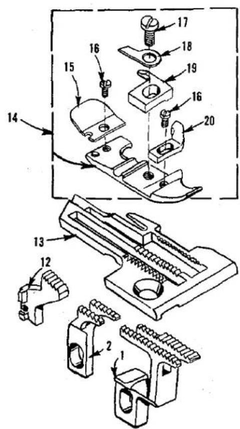
text_image
Technical diagram of a mechanical assembly with numbered parts, likely for assembly or repair instructions.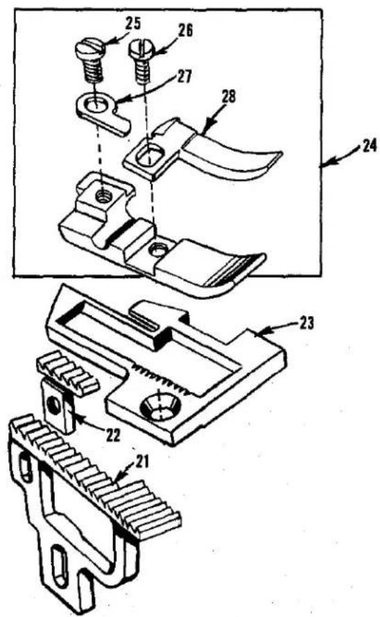
text_image
Technical diagram of mechanical assembly with numbered parts, likely a tool or component assembly.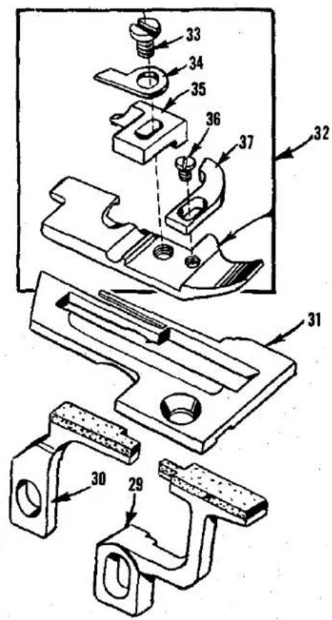
text_image
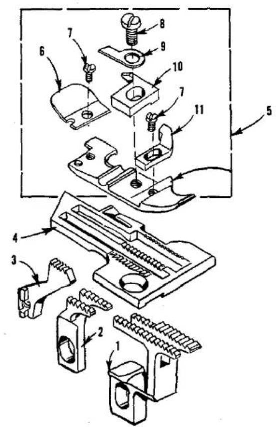
Technical diagram of mechanical assembly with numbered parts, likely a valve or clamp mechanismFEED DOGS, THROAT PLATES AND PRESSER FEET
| Ref.No. | PartNo. | Description | Amt.Req. |
| 1 | 39526 B | Feed Dog, differential, 16 t.p.i., for Styles XQA, XQB,CXQA, CXQB, XSQB, CXSQB | 1 |
| 2 | 39505 B | Feed Dog, main, marked "B", 16 t.p.i., for Styles XQA, XQB,CXQA, CXQB, XSQB, CXSQB | 1 |
| 3 | 39505 C | Feed Dog, chaining, marked "C", 20 t.p.i., for Styles XQA,CXQA | 1 |
| 4 | 39524 C-3/32 | Throat Plate, marked "AC-3/32", for 3/32 inch (2.4mm) wide seam, Styles XQA, CXQA | 1 |
| - | 39524 C-1/8 | Throat Plate, marked "AC-1/8", for 1/8 inch (3.2mm) wide seam, Styles XQA, CXQA | 1 |
| 5 | 39520 B | Presser Foot, Styles XQA, CXQA | 1 |
| 6 | 39530 C | Shield, chain | 1 |
| 7 | 22738 B | Screw, chain shield and chip guard | 2 |
| 8 | 22768 B | Screw, stitch tongue and hinge spring | 1 |
| 9 | 39530 | Spring, hinge | 1 |
| 10 | 39597 A | Tongue, stitch, marked "DS" | 1 |
| 11 | 39530 P | Guard, chip | 1 |
| 12 | 39505 E | Feed Dog, chaining, 20 t.p.i., Styles XQB, CXQB, XSQB,CXSQB | 1 |
| 13 | 39524 B-3/32 | Throat Plate, marked "V-3/32", for 3/32 inch (2.4mm) wide seam, Styles XQB, CXQB, XSQB, CXSQB | 1 |
| - | 39524 B-1/8 | Throat Plate, marked "V-1/8", for 1/8 inch (3.2mm) wide seam, Styles XQB, CXQB, XSQB, CXSQB | 1 |
| - | 39524 B-5/32 | Throat Plate, marked "BH", for 5/32 inch (4.0mm) wide seam, Styles XQB, CXQB, XSQB, CXSQB | 1 |
| 14 | 39520 A | Presser Foot, Styles XQB, CXQB, XSQB, CXSQB | 1 |
| 15 | 39530 C | Shield, chain | 1 |
| 16 | 22738 B | Screw, chain shield and chip guard | 2 |
| 17 | 22768 B | Screw, stitch tongue and hinge spring | 1 |
| 18 | 39530 | Spring, hinge | 1 |
| 19 | 39597 A | Tongue, stitch, marked "DS" | 1 |
| 20 | 39530 P | Guard, chip | 1 |
| 21 | 39505 J | Feed Dog, main 16 t.p.i., Styles XQJ, CXQJ | 1 |
| 22 | 39505 K | Feed Dog, chaining, marked "K", 16 t.p.i., Styles XQJ,CXQJ | 1 |
| 23 | 39524 J | Throat Plate, Styles XQJ, CXQJ | 1 |
| 24 | 39520 L | Presser Foot, Styles XQJ, CXQJ | 1 |
| 25 | 22768 B | Screw, hinge spring | 1 |
| 26 | 22819 | Screw, stitch tongue | 1 |
| 27 | 39530 | Spring, hinge | 1 |
| 28 | 39597 L | Tongue, stitch, marked "DW" | 1 |
| 29 | 39526 AB | Feed Dog, differential, vulcanized rubber feed surface,Style XTA | 1 |
| 30 | 39505 AB | Feed Dog, main, marked "AG", vulcanized rubber feed surface, Style XTA | 1 |
| 31 | 39524 AV | Throat Plate, marked "BZ", 1/16 to 3/32 inch (1.6 to 2.9mm)wide seam, Style XTA | 1 |
| 32 | 39520 AS | Presser Foot, Style XTA | 1 |
| 33 | 22768 B | Screw, stitch tongue and hinge spring | 1 |
| 34 | 39530 | Spring, hinge | 1 |
| 35 | 39597 AS | Tongue, stitch, marked "ES" | 1 |
| 36 | 22738 B | Screw, chip guard | 1 |
| 37 | 39530 P | Guard, chip | 1 |
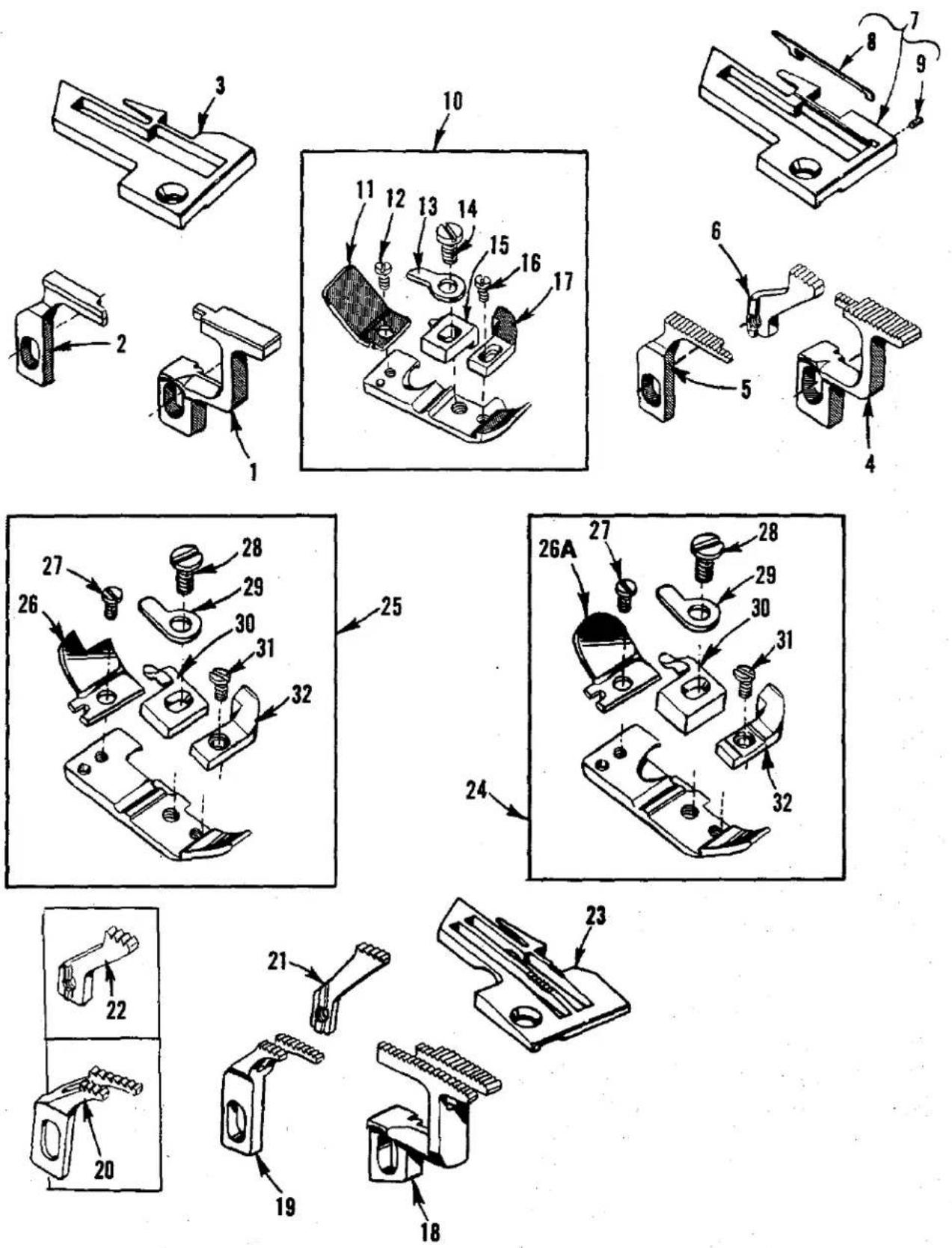
FEEDS DOGS, THROAT PLATES AND PRESSER FEET
| Ref.No. | PartNo. | Description | Amt.Req. |
| 1 | 39526 AB | Feed Dog, differential, vulcanized rubber feed surface,Style XRB | 1 |
| 2 | 39505 AB | Feed Dog, main, marked "AG", vulcanized rubber feed surface, Style XRB | 1 |
| 3 | 39524 AB-1/8 | Throat Plate, marked "AX-1/8", for 1/8 inch (3.2mm) wide seam, Style XRB | 1 |
| - | 39524 AB-5/32 | Throat Plate, marked "AX-5/32", for 5/32 inch (4.0mm) wide seam, Style XRB | 1 |
| - | 39524 AC | Throat Plate, marked "AV", Style XRC-045 | 1 |
| 4 | 39526 AC | Feed Dog, differential, 22 t.p.i., Style XRC | 1 |
| 5 | 39505 AC | Feed Dog, main, marked "AM", 22 t.p.i., Style XRC | 1 |
| 6 | 39505 E | Feed Dog, chaining, 20 t.p.i., Style XRC | 1 |
| 7 | 39528 AH | Throat Plate, marked "AY", Style XRC-060 | 1 |
| 8 | 39531 AD | Tongue, stitch | 1 |
| 9 | 22799 AE | Screw | 1 |
| 10 | 39520 AB | Presser Foot, Style XRB | 1 |
| - | 39520 AC | Presser Foot, Style XRC | 1 |
| 11 | 39530 S | Shield, chain, for presser foot No. 39520 AB | 1 |
| - | 39530 R | Shield, chain, for presser foot No. 39520 AC | 1 |
| 12 | 22738 | Screw, chain shield | 1 |
| 13 | 39530 G | Spring, hinge | 1 |
| 14 | 22768 B | Screw, stitch tongue and hinge spring | 1 |
| 15 | 39597 AB | Tongue, stitch, marked "EK" | 1 |
| 16 | 22738 | Screw, chip guard | 1 |
| 17 | 39530 P | Guard, chip | 1 |
| 18 | 39526 H | Feed Dog, differential, 20 t.p.i., Styles XRN, XSD,CXRN, CXSD | 1 |
| 19 | 39505 F | Feed Dog, main, marked "F" 20 t.p.i., Styles XSD,CXSD | 1 |
| 20 | 39505 BH | Feed Dog, main, marked "CM", 16 t.p.i., Styles XRN,CXRN | 1 |
| 21 | 39505 H | Feed Dog, chaining, marked "U", 20 t.p.i., Styles XSD,CXSD | 1 |
| 22 | 39505 AL | Feed Dog, chaining, marked "CN", 16 t.p.i., Styles XRN, CXRN | 1 |
| 23 | 39524 D | Throat Plate, marked "AM", Styles XRN, XSD, CXRN, CXSD | 1 |
| 24 | 39520 H | Presser Foot, Styles XSD, CXSD | 1 |
| 25 | 39520 BH | Presser Foot, Styles XRN, CXRN | 1 |
| 26 | 39530 E | Shield, chain, for presser foot No. 39520 H | 1 |
| 26A | 39530 U | Shield, chain, for presser foot No. 39520 BH | 1 |
| 27 | 22738 | Screw, chain shield | 1 |
| 28 | 22768 B | Screw, stitch tongue and hinge spring | 1 |
| 29 | 39530 | Spring, hinge | 1 |
| 30 | 39597 A | Tongue, stitch, marked "DS" | 1 |
| 31 | 22738 | Screw, chip guard | 1 |
| 32 | 39530 B | Guard, chip | 1 |
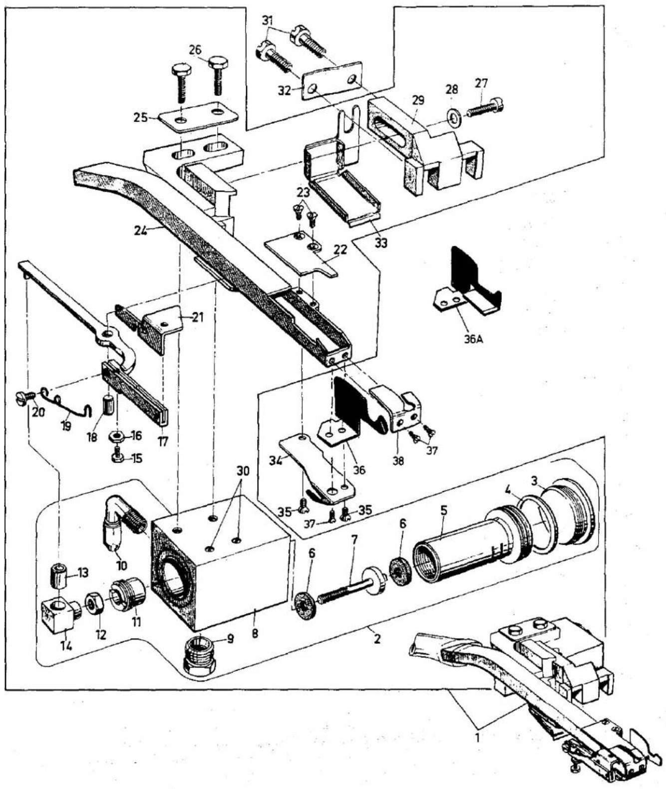
text_image
Exploded view diagram of a mechanical assembly with numbered components and labeled partsPOWER "AIR-KLIPP"®CHAIN CUTTER (STYLES CXQA, CXQB, CXQJ, CXRN, CXSD, CXSQB)
| Ref. No. | Part No. | Description | Amt. Req. |
| 1 | V29941 A | Power "AIR-KLIPP" Chain Cutter Assembly | 1 |
| 2 | 671 H-1 | Air-Motor Assembly | 1 |
| 3 | 671 H-1D | Screw, plug | 1 |
| 4 | 671 H-1F | Bumper, rubber | 1 |
| 5 | 671 H-1A | Vibrator | 1 |
| 6 | 671 H-1H | Washer, shock | 2 |
| 7 | 39536 DC | Stud | 1 |
| 8 | 671 H-1B | Housing | 1 |
| 9 | 660-763 | Muffler | 1 |
| 10 | 999-141 | Elbow, union | 1 |
| 11 | 671 H-1E | Screw, plug | 1 |
| 12 | 41071 G | Nut | 1 |
| 13 | 671 H-1G | Bushing | 1 |
| 14 | 39573 AC | Link, drive | 1 |
| 15 | 22588 K | Screw, lower knife adjusting | 1 |
| 16 | 60078 Z | Nut | 1 |
| 17 | 39573 AB | Lever, knife driving | 1 |
| 18 | 39536 DB | Pin | 1 |
| 19 | 99697 DA | Spring, torsion | 1 |
| 20 | 22825 | Screw | 1 |
| 21 | 99669 K | Knife, lower | 1 |
| 22 | 99670 L | Knife, upper | 1 |
| 23 | 22716 | Screw | 2 |
| 24 | 99676 MA | Tube Assembly | 1 |
| 25 | 95910 A | Plate, washer | 1 |
| 26 | 906 | Screw | 2 |
| 27 | 22729 D | Screw | 1 |
| 28 | 80265 | Washer | 1 |
| 29 | 99663 KA | Bracket | 1 |
| 30 | 12935 A | Screw, set | 2 |
| 31 | 99373 C | Screw, mounting | 2 |
| 32 | 95910 B | Plate, washer | 1 |
| 33 | 39534 RB | Shield, oil | 1 |
| 34 | 99664 C | Guide, looper thread | 1 |
| 35 | 22716 | Screw | 2 |
| 36 | 99665 | Guard, fabric, Styles CXQA, CXQB, CXQJ, CXSQB | 1 |
| 36A | 99665 A | Guard, fabric, Styles CXRN, CXSD | 1 |
| 37 | 22716 A | Screw, inlet part and fabric guard | 3 |
| 38 | 99677 HA | Inlet Part, marked "GS", has a .028 inch (.7mm) slot and .169 inch (4.3mm) opening. For threads 60/3 up to 40/4 | 1 |
| - | 99677 HB | Inlet Part, marked "GF", has a .020 inch (.5mm) slot and .138 inch (3.5mm) opening. For thin threads up to size 70/3 | 1 |
| - | 99677 HD | Inlet Part, marked "GV", has a .039 inch (1.0mm) slot and .205 inch (5.2mm) opening. For heavy threads such as 30/6 | 1 |
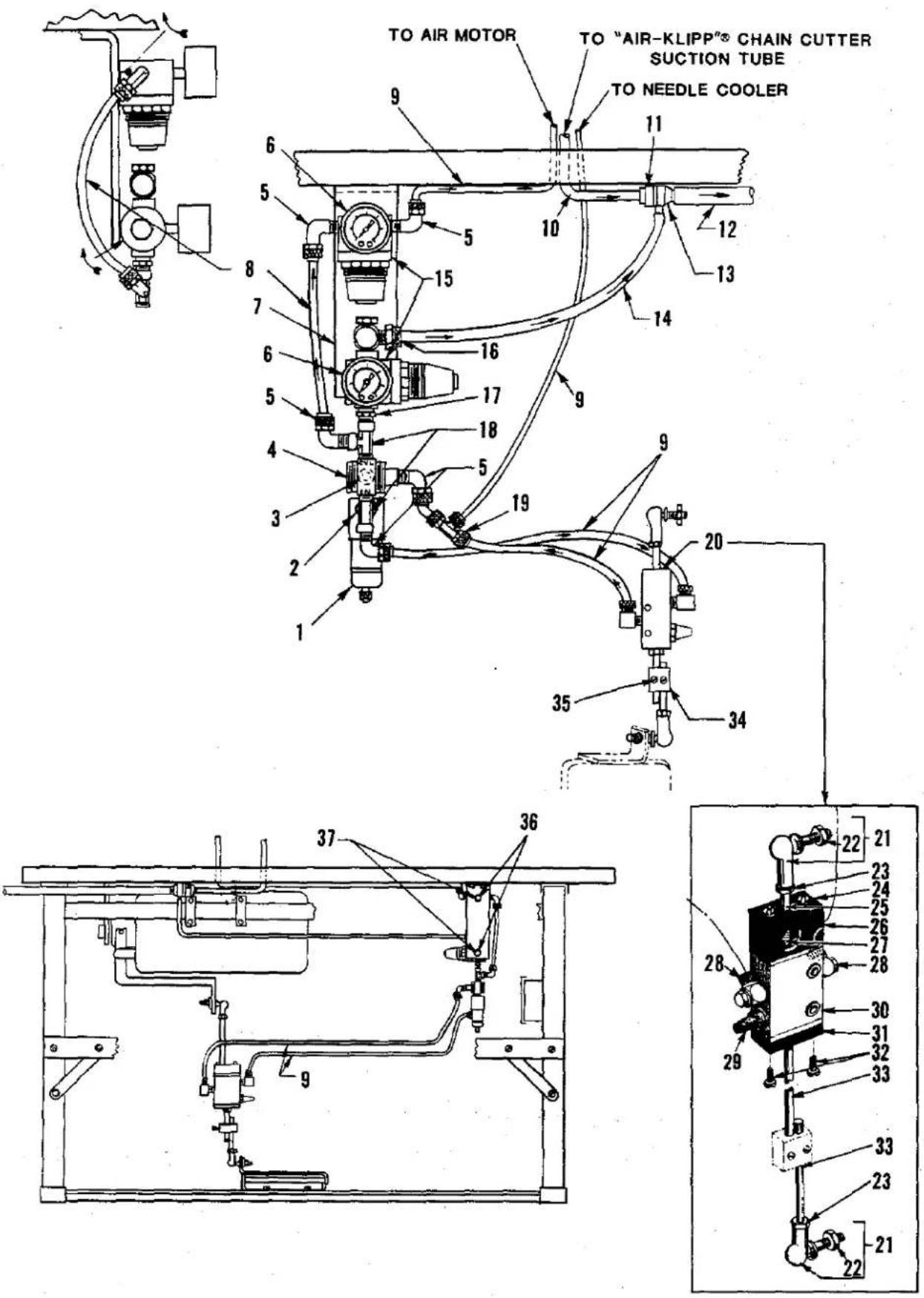
text_image
TO AIR MOTOR TO "AIR-KLIPP"® CHAIN CUTTER SUCTION TUBE TO NEEDLE COOLER 9 11 10 12 13 14 6 5 8 7 6 5 4 3 2 1 16 17 18 5 19 9 20 35 34 36 37 22 21 23 24 25 26 27 28 30 31 32 33 23 21 9VENTURI TUBE, PNEUMATIC CONTROL DEVICE, TREADLE ROD VALVE
| Ref.No. | PartNo. | Description | Amt.Req. |
| 1 | GR-671 D-5 | Filter, air line | 1 |
| 2 | RM3320-1 | Nipple, reducing | 1 |
| 3 | 660-403 | Muffler | 1 |
| 4 | RM4098-1 | Valve, pilot | 1 |
| 5 | 660-401 | Elbow, 90° | 5 |
| 6 | 671 D-15 | Gauge, pressure | 2 |
| 7 | 99683 CC | Bracket, mounting | 1 |
| 8 | 660-392 | Tube, air, 1/4 inch O.D. x 6 1/2 inches (165.1mm) long - | 1 |
| 9 | RM2997 D | Tube, air, 1/4 inch O.D. (specify length) | as Req. |
| 10 | 671 B-12 | Tube, suction | 1 |
| 11 | 998-332 | Holder, venturi | 1 |
| 12 | 671 B-11 | Tube, discharge | 1 |
| 13 | 671 D-2 | Venturi | 1 |
| 14 | 99675-1500 | Tube, venturi supply | 1 |
| 15 | 671 D-9 | Regulator, pressure | 2 |
| 16 | 999-217 | Connector | 1 |
| 17 | RM3287-2 | Nipple, hex | 1 |
| 18 | RM2850 D | Tee, pipe | 2 |
| 19 | RM3384-1 | Tee, union | 1 |
| 20 | 99683 HC-155 | Valve Assembly, treadle rod | 1 |
| 21 | 999-146 | Link | 2 |
| 22 | 95250 | Nut | 1 |
| 23 | 95250 | Nut | 3 |
| 24 | 95073 | Screw | 2 |
| 25 | 99683 J | Stud | 1 |
| 26 | 99683 K | Guide | 1 |
| 27 | 110-4 | Spring | 1 |
| 28 | 999-127 | Elbow, 90° | 2 |
| 29 | 999-140 | Muffler | 1 |
| 30 | 999-139 | Valve, cam, 3/2 way | 1 |
| 31 | 99683 E | Connection | 1 |
| 32 | 95151 | Screw | 2 |
| 33 | 99563 A-155 | Rod | 2 |
| 34 | 671-2 | Block, mounting | 1 |
| 35 | 91 D | Screw | 2 |
| 36 | 671 C-16 | Stud, mounting | 2 |
| 37 | 11635 B | Nut | 2 |
| RM2871 B | Tie, cable (Not Shown) | 4 | |
| 660-870 | Mount, cable tie (Not Shown) | 4 | |
| 671 F-1 | Fitting, barb, air filter inlet (Not Shown) | 1 | |
| 671 F-6 | Bushing, reducing, air filter inlet (Not Shown) | 1 |
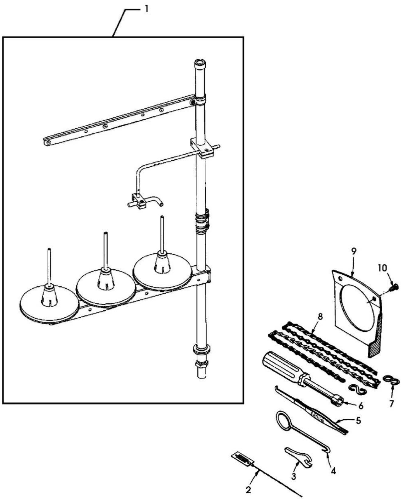
text_image
Technical diagram of a mechanical assembly with numbered parts, including a lever mechanism and exploded view of components.THREAD STANDS, ACCESSORIES AND MISCELLANEOUS TOOLS
| Ref.No. | PartNo. | Description | Amt.Req. |
| 1 | GR-21101W3 | Thread stand | 1 |
| 2 | 39899 A | Wire, threading | 1 |
| 3 | 116 | Wrench, open end | 1 |
| 4 | 21227 DR | Extractor, cam | 1 |
| 5 | 660-240 | Tweezers, thread | 1 |
| 6 | 21388 AU | Wrench, socket, 3/8 inch (9.5mm) hexagon | 1 |
| 7 | 660-264 | "S" Hook | 2 |
| 8 | 421 D-34 | Chain, presser foot lifter, 32 3/64 inch (812.8mm) long | 1 |
| 9 | 21375 BB | Guard, belt | 1 |
| 10 | 80 | Screw | 2 |
| * | 660-458 | Cover, dust | 1 |
| * | 28604 R | Container of Oil, 16 ounces (455 ml) Spec. 175 | 1 |
| * | 21393 AC | Pan, oil drip | 1 |
| * | NA-12 | Nail, oil drip pan | 8 |
| * | 652-24 | Washer, (shim) all Styles except XRC, XQJ, XRN, XSD, CXQJ,CXRN, CXSD | 8 |
| * | 144-36 | Isolators | 6 |
| * | 650-24 | Bolts with Nuts | 3 |
| * | 22820 A | Screw, hexagon head | 3 |
* Not shown on illustration.
NUMERICAL INDEX OF PARTS
| Part No. | Page No. | Part No. | Page No. | Part No. | Page No. | Part No. | Page No. |
| WA9 A....57 | 660-764....33 | 21375 BB....57 | 22782 A....37,39 | ||||
| NA-12....57 | 660-824....43 | 21375 BR....31 | 22791 H....47 | ||||
| 30-106 B1k....33 | 660-828....31 | 21388 AU....57 | 22797 A....35 | ||||
| 40-46....47 | 660-835....33 | 21393 AC....57 | 22799 B....45 | ||||
| 51-288 B1k....33 | 660-841....31 | 21695 AT....27 | 22799 AE....51 | ||||
| 69 S....57 | 660-870....55 | 21695 AU....27 | 22806 A....47 | ||||
| 73 C....45 | 666-94....33 | 22503 F....41 | 22810....57 | ||||
| 73 X....47 | 666-295....31 | 22513....29 | 22819....49 | ||||
| HA73 B....45 | 667 D-8....27 | 22513 C....45 | 22820 A....57 | ||||
| 77....41 | 671-2....55 | 22513 D....37,39 | 22825....53 | ||||
| 78....43 | 671-17....27 | 22524....43 | 22847 B....47 | ||||
| 79-33....31 | 671 B-11....55 | 22528....35,39 | 22873 C....45 | ||||
| 80....57 | 671 B-12....55 | 22541....27 | 22892 B....43 | ||||
| 86 X....29 | 671 C-13....27 | 22541 B....31,35,39 | 22894 C....41 | ||||
| 87....35,39 | 671 C-16....55 | 22559 H....45 | 22894 AE....27,41 | ||||
| 87 C....33,37,39,41 | 671 D-2....55 | 22561....35 | 28604 R....57 | ||||
| 671 D-5....55 | 22562 A....41 | 29126 DF....41 | |||||
| 88....47 | 671 D-9....55 | 22564 D....27 | 29477 GW....27 | ||||
| 88 B....37,39,45 | 671 D-15....55 | 22565....27,41 | 29477 MC....33 | ||||
| 90....27,29,45 | 671 F-1....55 | 22565 C....57 | 29477 MS....33 | ||||
| 91 D....55 | 671 F-4....27 | 22565 D....27 | 29481 L....45 | ||||
| 93 A....35 | 671 F-6....55 | 22565 F....27,33,V29941A....53 | |||||
| 97....41 | 671 F-62....27 | 35,39 | 39151....41 | ||||
| 97 A....33 | 671 H-1....53 | 22565 H....41 | 39158 U....29 | ||||
| 107....57 | 671 H-1A....53 | 22565 S....27,41 | 39501 D....29 | ||||
| 108....57 | 671 H-1B....53 | 22566 B....47 | 39501 K....27,29 | ||||
| 109....57 | 671 H-1D....53 | 22569....27 | 39501 M....29 | ||||
| 110-4....55 | 671 H-1E....53 | 22569 B....27,29,35,39,47 | 39501 AP....29 | ||||
| 116....57 | 671 H-1F....53 | 39,47 | 39501 DC....29 | ||||
| 138....29 | 671 H-1G....53 | 22569 C....47 | 39501 DD....29 | ||||
| 144-36....57 | 671 H-1H....53 | 22569 D....29,39,47 | 39501 DG....29 | ||||
| 154 GAS....37,39 | 906....53 | 22569 G....35,39 | G39501 D....29 | ||||
| 154 GDS....37 | 998-332....55 | 22569 K....27 | 39503 A....47 | ||||
| 154 GFS....37 | 999-127....55 | 22569 T....31 | 39503 C....47 | ||||
| 162 SAS....37 | 999-139....55 | 22569 X....33 | 39503 D....47 | ||||
| 222 D....45 | 999-140....55 | 22571 E....27 | 39503 L....45 | ||||
| 258 A....47 | 999-141....53 | 22585 A....43 | 39505 B....49 | ||||
| 303....45 | 999-146....55 | 22585 G....45 | 39505 C....49 | ||||
| SC333 A....57 | 999-217....55 | 22585 R....27 | 39505 E....49,51 | ||||
| 376 A....47 | 1025 L....41 | 22586 T....31 | 39505 F....51 | ||||
| 421 D-34....57 | RM2813-1....31 | 22587 J....43 | 39505 H....51 | ||||
| 482 C....41 | RM2813-4....31 | 22587 M....33 | 39505 J....39,49 | ||||
| 604....47 | RM2850 D....55 | 22588 J....43 | 39505 K....39,49 | ||||
| 605....47 | RM2871 B....55 | 22588 K....53 | 39505 AB....49,51 | ||||
| 605 A....43 | RM2997 D....55 | 22593....45 | 39505 AC....51 | ||||
| 627....47 | RM3287-2....55 | 22596 E....37,39 | 39505 AL....51 | ||||
| 650-24....57 | RM3320-1....55 | 22596 H....33 | 39505 BH....51 | ||||
| 651 A-16....57 | RM3384-1....55 | 22597 E....47 | 39508 A....41 | ||||
| 652-16....57 | RM4098-1....55 | 22635 C-12....31 | 39508 B....41 | ||||
| 652-24....57 | 6042 A....43 | 22650 CB-4....31,57 | 39520 A....49 | ||||
| 652 J-16....57 | 8372 A....35,39,47 | 22650 CD-4....33,57 | 39520 B....49 | ||||
| 652 J-24....57 | 11635 B....55 | 22650 CE-6....57 | 39520 H....51 | ||||
| 660-142....47 | 12538....47 | 22652 B-12....31 | 39520 L....49 | ||||
| 660-206....41 | 12865....47 | 22652 D-6....31 | 39520 AB....51 | ||||
| 660-207....37,39 | 12935 A....53 | 22653 B-12....43 | 39520 AC....51 | ||||
| 660-210....29 | 12957 E....47 | 22657 D-12....29 | 39520 AS....49 | ||||
| 660-240....57 | 14077....43 | 22716....53 | 39520 BH....51 | ||||
| 660-243....27 | 14077 A....37,39 | 22716 A....53 | 39521 D....33 | ||||
| 660-264....57 | 21104 H....57 | 22726 A....47 | 39521 H....33 | ||||
| 660-372....27 | 21104 V....57 | 22729 A....45 | 39524 B-3/32....49 | ||||
| 660-392....55 | 21104 AA....57 | 22729 B....43 | 39524 B-1/8....49 | ||||
| 660-401....55 | 21113 C....57 | 22729 D....41,53 | 39524 B-5/32....49 | ||||
| 660-403....55 | 21113 F....57 | 22729 E....41 | 29524 C-3/32....49 | ||||
| 660-443....33 | 21114 S-4....57 | 22738....43,51 | 39524 C-1/8....49 | ||||
| 660-458....57 | 21114 T....57 | 22738 B....49 | 39524 D....51 | ||||
| 660-459....43 | 21114 U....57 | 22738 G....47 | 39524 J....49 | ||||
| 660-550....31 | 21130 W-2....57 | 22743....27,45 | 39524 AB-1/8....51 | ||||
| 660-695....31 | 21130 W-3....57 | 22747 B....33 | 39524 AB-5/32....51 | ||||
| 660-700....31 | 21227 DR....57 | 22758 E....47 | 39524 AC....51 | ||||
| 660-705....27 | 21237 CR....27 | 22768 B....39,41,49,51 | 39524 AV....49 | ||||
| 660-716....31 | 21237 CT....31 | 51 | 39525 D....45 | ||||
| 660-717....31 | 21237 CW....31 | 22768 C....33 | 39525 E....45 | ||||
| 660-726....31 | 21237 DK....27 | 22769 B....33 | 39525 H....43 | ||||
| 660-731....31 | 21237 DM....31 | 22781....47 | 39525 J....43 | ||||
| 660-763....53 | 21237 DN....31 | 22781 A....33,35,39 | 39525 K....45 |
NUMERICAL INDEX OF PARTS
| Part No. | Page No. | Part No. | Page No. | Part No. | Page No. | Part No. | Page No. |
| 39525 | L....43 | 39544 | S....41 | 39573 | H....43 | 39592 | AL....41 |
| 39525 | R....43 | 39544 | U....41 | 39573 | J....43 | 39592 | AM....41 |
| GA39525 | N....43 | 39544 | V....41 | 39573 | K....33 | 39592 | AF-1....41 |
| 39526 | B....49 | 39544 | X....33 | 39573 | AA....33 | 39592 | AR-2....41 |
| 39526 | H....51 | 39549 | C....43 | 39573 | AB....53 | 39592 | AR-4....41 |
| 39526 | AB....49,51 | 39549 | CJ....43 | 39573 | AC....53 | 39592 | AR-5....41 |
| 39526 | AC....51 | 39550 | C....43 | 39578 | F....29 | 39592 | AR-6....41 |
| 39528 | AH....51 | 39550 | E....43 | 39578 | P....35,39 | 39593 | C....27 |
| 39530 | ....49,51 | 39550 | J....45 | 39578 | T....29 | 39593 | C....27 |
| 39530 | B....51 | 39550 | K....45 | 39578 | U....29 | 39593 | H....27 |
| 39530 | C....49 | 39550 | M....45 | 39578 | V....35 | 39594 | G....29 |
| 39530 | E....51 | 39550 | T....45 | 39578 | AL....29 | 39594 | H....29 |
| 39530 | G....51 | 39550 | Z....45 | 39578 | AX....29 | 39594 | N....35,37 |
| 39530 | P....49,51 | 39550 | AB....43 | 39578 | AY....29 | 39,41 | |
| 39530 | R....51 | 39550 | AC....43 | G39578 | M....35,39 | 39594 | R....27 |
| 39530 | S....51 | 39550 | AD....43 | 39580 | A....43 | 39594 | X....31 |
| 39530 | U....51 | 39550 | AE....43 | 39580 | E....43 | 39594 | Y....27 |
| 39530 | AH....47 | 39550 | AF....43 | 39580 | F....43 | 39595 | ....51 |
| 39531 | AD....51 | 39551 | H....37 | 39580 | AE....43 | 39597 | A....49,51 |
| 39532 | A....29 | 39551 | J....37,39 | 39580 | BA....45 | 39597 | L....49 |
| 39532 | D....29 | 39552 | P....33 | 39582 | D....29 | 39597 | AB....51 |
| 39534 | ....35 | 39552 | R....37,39 | 39582 | F....31 | 39597 | AS....49 |
| 39534 | G....35,39 | 39552 | U....33 | 39582 | H....29 | 39743 | ....41 |
| 39534 | R....27 | 39552 | Z....37,39 | 39582 | J....29 | 39772 | ....43 |
| 39534 | AF....35,39 | 39552 | AA....37 | 39582 | K....29 | 39835 | G....35,39 |
| 39534 | RB....27,53 | 39552 | AB....37 | 39582 | BS....45 | 39843 | H....41 |
| 39535 | C....35,39 | 39552 | AD....37,39 | 39582 | BZ....27 | 39855 | ....47 |
| 39535 | D....35,39 | 39552 | AG....37,39 | 39582 | DP....31 | 39868 | H....47 |
| 39535 | F....39 | 39552 | AJ....37 | 39582 | DS....27 | 39878 | C....29 |
| 39535 | V....35,39 | 39555 | B....47 | 39582 | DT....31 | 39880 | N....43 |
| 39535 | W....35 | 39555 | C....47 | 39582 | DU....31 | 39899 | A....57 |
| 39536 | D....39 | 39555 | D....47 | 39582 | DV....27 | 41071 | G....29,53 |
| 39536 | E....35,39 | 39555 | F....47 | 39582 | DY....31 | 43139 | A....47 |
| 39536 | CT....35 | 39555 | P....33 | 39582 | DZ....31 | 43443 | Q....29 |
| 39536 | CU....37,39 | 39555 | R....33 | 39582 | EA....29 | C50043 | F....37,39 |
| 39536 | CV....35,39 | 39555 | AA....47 | 39582 | EN....31 | C50093 | U....31 |
| 39536 | CW....35 | 39556 | A....27 | 39582 | ES....31 | 51292 | F-1....55 |
| 39536 | CX....35 | 39556 | D....47 | 39589 | AA....45 | 51295 | B....31 |
| 39536 | CY....35,39 | 39556 | J....47 | 39589 | AB....45 | 53634 | C....35,39 |
| 39536 | CZ....31 | 39556 | L....47 | 39589 | AC....45 | 53658 | A....47 |
| 39536 | DA....31 | 39556 | M....47 | 39589 | AD....45 | 55235 | D....43 |
| 39536 | DB....53 | 39556 | N....35 | 39589 | AE-1/2....45 | 55235 | E....43 |
| 39536 | DC....53 | 39556 | T....47 | 39589 | AE-3/4....45 | 60078 | Z....53 |
| 39538 | A....35,39 | 39557 | A....27 | 39589 | AE-1....45 | 61303 | D....45 |
| 39540 | M-5 1/2....39 | 39557 | B....27 | 39589 | AF....45 | 79077 | ....45 |
| 39540 | M-7....35 | 39557 | C....27 | 39589 | AG....45 | 80265 | ....53 |
| 39540 | M-8....35 | 39557 | E....27 | 39589 | AH....45 | 95073 | ....55 |
| 39540 | M-9....37 | 39557 | F....27 | 39589 | AJ....45 | 95151 | ....55 |
| 39540 | M-10....35 | 39557 | H....27 | 39589 | AK-1/2....45 | 95250 | ....55 |
| 39540 | M-12....37 | 39560 | A....41 | 39589 | AK-3/4....45 | 95910 | A....53 |
| 39540 | M-14....37 | 39560 | B....41 | 39589 | AK-1....45 | 95910 | B....53 |
| 39540 | M-18....35 | 39563 | D....47 | 39589 | AL....45 | 99373 | C....53 |
| 39540 | M-20....37 | 39563 | H....47 | 39590 | D....33 | 99563 | A-155....55 |
| 39540 | M-30....35,37 | 39563 | N....47 | 39590 | H....33 | 99663 | KA....53 |
| 39540 | R....39 | 39563 | P....37 | 39590 | J....33 | 99664 | A....47 |
| 39541 | C....33 | 39563 | AA....39 | 39590 | N....33 | 99664 | C....53 |
| 39541 | D....31 | 39563 | AC....37,39 | 39590 | T....33 | 99665 | ....53 |
| 39542 | A....31 | 39568 | B....47 | 39590 | Y....33 | 99665 | A....53 |
| 39543 | E....41 | 39568 | D....47 | 39590 | Z....33 | 99669 | K....53 |
| 39543 | M....41 | 39568 | E....47 | 39590 | AB....33 | 99670 | L....53 |
| 39543 | P....41 | 39568 | G....27 | 39591 | A....33 | 99675-1500... | 55 |
| 39543 | S....41 | 39568 | J....27,45 | 39591 | B....33 | 99676 | MA....53 |
| 39543 | T....41 | 39568 | L....47 | 39591 | K....33 | 99677 | HA....53 |
| 39543 | W....41 | 39568 | W....47 | 39592 | D....57 | 99677 | HB....53 |
| 39543 | X....41 | 39568 | AC....37 | 39592 | E....57 | 99677 | HD....53 |
| 39543 | Y....37,39 | 39568 | AH....37,39 | 39592 | W....57 | 99679 | ....29 |
| 39543 | Z....41 | 39570 | C....43 | 39592 | Z....47 | 99683 | E....55 |
| 39543 | AA....35,39 | 39570 | CJ....43 | 39592 | AA....47 | 99683 | J....55 |
| 39543 | AC....41 | 39571 | B....43 | 39592 | AB....47 | 99683 | K....55 |
| 39543 | AF....41 | 39571 | C....43 | 39592 | AC....47 | 99683 | CC....55 |
| 39544 | ....41 | 39571 | D....43 | 39592 | AD....47 | 99683 | HC-155... |
| 39544 | B....41 | 39571 | F....43 | 39592 | AF....47 | 99697 | DA....53 |
| 39544 | D....41 | 39572 | ....43 | 39592 | AG-3....47 | ||
| 39544 | J....41 | 39573 | A....43 | 39592 | AH....47 | ||
| 39544 | N....41 | 39573 | E....43 | 39592 | AK....47 |
Union Special Corporation
Corporate Office
One Union Special Plaza
Huntley, IL 60142
Phone: 847·669·5101
Fax: 847·669·4454
Union Special GmbH
EuropeanDistributionCenter
Raiffeisenstrasse 3
D-71696 Möglingen, Germany
Tel: 49·07141·247·0
Fax: 49·07141·247·100
JUKI CORPORATION
INTERNATIONAL SALES DIVISION
8-2-1, KOKURYO - CHO,