A4 - Receiver Adastra - Free user manual and instructions
Find the device manual for free A4 Adastra in PDF.


User questions about A4 Adastra
0 question about this device. Answer the ones you know or ask your own.
Ask a new question about this device
Download the instructions for your Receiver in PDF format for free! Find your manual A4 - Adastra and take your electronic device back in hand. On this page are published all the documents necessary for the use of your device. A4 by Adastra.
USER MANUAL A4 Adastra
Rackmount Stereo Amplifier with Media Player
Item ref: 953.404UK
User Manual

text_image
adastra 0 SD/MAC CVD POWER MODE REP H4 HE HM EQ AUX MEDIA LINE 1 LINE 2 AUX IN MIC1 MIC2 MIC1 MIC2 TALK OVER LINE1 LINE2 BASS TREBLE CH1 CH2 MICA PLAYER AUX - -13 +12 -13 +12 CLIP SRS AUX LINE1 LINE2 BASS TREBLE CH3 CH4 MICA PLAYER AUX - -13 +12 -13 +12 CLIP SRS AUX AUX AUX AUX AUX AUX AUX AUX AUX AUX AUX AUX AUX AUX AUX AUX AUX AUX AUX AUX AUX AUX AUX AUX AUX AUX AUX AUX AUX AUX AUX AUX AUX AUXVersion 2.0

Caution: Please read this manual carefully before operating
Damage caused by misuse is not covered by the warranty
Introduction
Thank you for choosing the Adastra A4 rackmount dual stereo amplifier to power your public address system. This amplifier is designed to offer high quality, reliable service for mobile and installed systems. Please read this manual fully and follow the instructions to achieve the best results with your new purchase and to avoid damage through misuse.
SAFETY SYMBOL AND MESSAGE CONVENTIONS

CAUTION RISK OF ELECTRIC SHOCK DO NOT OPEN
AVIS RISQUE DE CHOC ELECTRIQUE NE PAS OUVRIR


This symbol indicates that dangerous voltage constituting a risk of electric shock is present within this unit

This symbol indicates that there are important operating and maintenance instructions in the literature accompanying this unit.

SAFETY NOTICE
- Prior to use, read through this manual
- Keep the manual in good condition
- Pay attention to safety warnings
- Observe all operating requirements
- Do not use the device near water or wet areas
- For cleaning, only use a lint-free, dry cloth
- Install according to the specifications
- Place away from heat sources or heating appliances
- Use mains lead provided and avoid damage to cable or connectors
- Unplug power from mains during stormy weather or if unused for long periods
- In case of malfunction, water ingress or other damage, consult qualified service personnel
- Do not place in damp areas or near liquids or moisture. Do not spill liquids on the housing
- Please pay attention to warning symbols during transit and placement
- Terminals marked with the 12 symbol are HAZARDOUS LIVE and should only be connected by qualified personnel
- Ensure that the apparatus is connected to a mains socket with a protective EARTH connection
- Ensure correct operation of the mains switch
Warning
To prevent the risk of fire or electric shock, do not expose any components to rain or moisture.
If liquids are spilled on the casing, stop using immediately, allow unit to dry out and have checked by qualified personnel before further use. Avoid impact, extreme pressure or heavy vibration to the case
No user serviceable parts inside – Do not open the case – refer all servicing to qualified service personnel.
Safety
- Check for correct mains voltage and condition of IEC lead before connecting to power outlet
• It is recommended to use speaker wire with a minimum current rating of 6A per output. - Do not allow any foreign objects to enter the case or through the ventilation grilles
Placement
- Keep out of direct sunlight and away from heat sources
- Keep away from damp or dusty environments
• For rack-mounting, use the rack ears provided and ensure adequate support for the weight of the amplifier - Ensure adequate air-flow and do not cover cooling vents
- Ensure adequate access to controls and connections
Cleaning
• Use a soft cloth with a neutral detergent to clean the casing as required
• Use a vacuum cleaner to clear ventilation grilles of any dust or debris build-ups
- Do not use strong solvents for cleaning the unit
Front panel
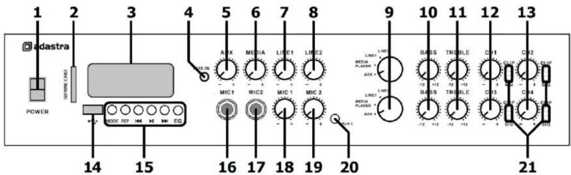
text_image
1 2 3 4 5 6 7 8 9 10 11 12 13 adastra POWER SDWRNC CAND MODE REP M EQ AUX MEDIA LINE1 LINE2 LIND1 MEDIA PLAYER * AUX * LINE1 MEDIA PLAYER * AUX * BASS TREBLE CH11 CHIP CHIP + CHIP -12 +12 -12 +12 -12 +12 -12 +12 - + SIO - + SIO - 20 21 14 15 16 17 18 19 20- Power on/off switch
- SD card slot
- Media player display
- 3.5mm stereo Aux input
- Aux input volume control
- Media player volume control
- Line 1 input volume control
- Line 2 input volume control
- Stereo input selector
- Bass EQ control
- Treble EQ control
- Channel 1 / 3 output level control
- Channel 2 / 4 output level control
- USB port
- Media player control panel
- Mic 1 input 6.3mm jack
- Mic 2 input 6.3mm jack
- Mic 1 volume control
- Mic 2 volume control
- Talkover on/off button
- Output Signal & Clip indicators
Rear panel
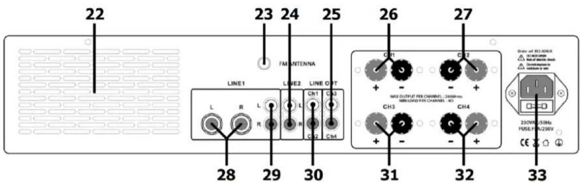
text_image
22 23 24 25 FM ANTENNA LINE1 LINE2 LINE OUT L R L Ch1 Ch3 R R Ch2 Ch4 28 29 30 26 27 CH1 CH2 + - + MAX OUTPUT PER CHANNEL: 2000Hz- MIN LOAD PER CHANNEL: NC CH3 CH4 + - + Order of 261.0kVA DC FOR OPEN Risk of electric shock Disinade taken rebease on 230V/250V FUSE/FN/230V CE- Ventilation grille (do not obstruct airflow)
- FM antenna connection (F type)
- Line 2 input (L+R RCA)
- Line output Ch3+Ch4
- Channel 1 speaker output +/- 4mm posts
-
Channel 2 speaker output +/- 4mm posts
-
Line 1 input (L+R 6.3mm jack)
- Line 1 input (L+R RCA)
- Line output Ch1+Ch2
- Channel 3 speaker output +/- 4mm posts
- Channel 4 speaker output +/- 4mm posts
- IEC mains inlet & fuse holder
Speaker connections
The A4 has 4 speaker output channels (Ch1, Ch2, Ch3, Ch4) which can be assigned as 2 independent stereo zones – i.e. Left 1 + Right 2 outputs and Left 3 + Right 4 outputs.
When connecting speakers, connect “−” to the “−” output terminal(s) and “+” to the “+” output terminal(s). Connect speakers with a combined impedance of no lower than 4Ω (4 Ohms) to each output channel.
- If the speakers are 8 impedance, you can connect up to 2 speakers in parallel to each channel.
- If the speakers are 16Ω impedance, you can connect up to 4 speakers in parallel to each channel.
Some example wiring diagrams are shown opposite with speakers connected in parallel.
The impedance of the load measured in "Ohms" (Ω) will also determine the power output.
The amplifier delivers its maximum power output at the minimum impedance rating (4Ω). Higher impedances result in a lower output.
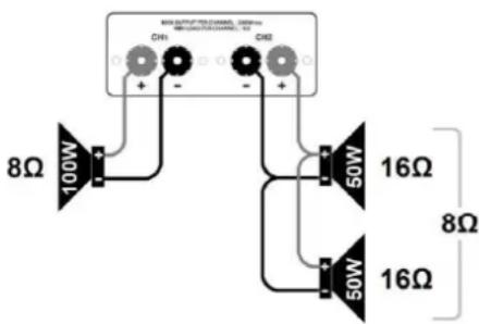
• Note: Some speakers have 4 impedance, in which case connect only 1 speaker to each channel.
The combined load on each output shares the power from the amplifier. If the amplifier is delivering 200W to 2 speakers connected in parallel with the same impedance, they must each be capable of handling 100W.
Input connections
The A4 has 2 mic inputs and 4 selectable stereo sources (one is the internal media player)
Connect wired microphone(s) to the Mic 1 and/or Mic 2 jack inputs (6.3mm) on the front panel (16, 17). The volume level of these is controlled by the Mic 1 and Mic 2 volume controls (18, 19)
A smart phone, tablet or mp3 player can be connected to the Aux jack (3.5mm) on the front panel (4) The volume level of this stereo input is controlled by the Aux volume control (5) To hear this input through the speakers, "AUX" must be set on the input selector (9) of either stereo zone.
On the rear panel, there are 2 further stereo line inputs for connecting CD/DVD players, DVB/DAB tuners etc. Line 1 input has a choice of Left + Right 6.3mm jack (28) or RCA inputs (29)
The volume level of this input is controlled by the Line 1 volume control (7)
To hear this input through the speakers, "LINE 1" must be set on the input selector (9) of either stereo zone. Line 2 has Left + Right RCA inputs (24)
The volume level of this input is controlled by the Line 2 volume control (8)
To hear this input through the speakers, "LINE 2" must be set on the input selector (9) of either stereo zone.
The mix of mic/line inputs to Ch1+Ch2 can be fed onto further equipment via the RCA line output (30) The mix of mic/line inputs to Ch3+Ch4 can be fed onto further equipment via the RCA line output (25)
For good reception of FM radio stations (if needed) in the media player, the A4 has an "F" connector on the rear panel (23) which can be connected to an external FM antenna (aerial)
Connect the IEC power inlet (33) to the 230Vac mains supply, using the IEC lead provided.
Operation
When all connections to the amplifier are made, turn all rotary controls down and switch on the power (1) and the media player display will illuminate.
Turn Bass and Treble controls (10, 11, 23, 24) to the 12 o'clock position (pointing straight up) and turn the Ch1, Ch2, Ch3 and Ch4 rotary controls (12, 13, 25, 26) up part way for testing.
If a microphone is connected to one of the mic inputs (17, 18) gradually increase the volume control for that channel (19,20) and speak into the mic until it is heard through the speakers.
Alternatively, play a signal into one of the aux or line inputs (4, 33, 34, 35) and ensure it is selected on the input selector (9, 22) and turn up its volume control (5, 7, 8) until the signal is heard through the speakers.
The same test applies for the internal media player (see section below) by playing a track or radio station. Select "MEDIA PLAYER" on the input selector (9, 22) and gradually increase the media player volume (6)
Turn up the Ch1, Ch2, Ch3 and Ch4 volume controls to the maximum required volume level and reduce the channel volume control if necessary.
The output of each speaker channel is represented on the SIG and CLIP LEDs (14) and care should be taken that the red CLIP LED is only lit momentarily during use. Anything longer than a short flash of this LED may be indicating distortion or clipping of the output signal and the output channel volume control should be turned down.
Any microphones connected should not be able to "hear" the speakers, which can cause feedback (squealing or howling) and should not be pointed towards the speakers. If this still happens, turn down the volume for that microphone and adjust Bass and/or Treble EQ controls to reduce the feedback.
If the TALKOVER feature (21) is switched on, speaking into the microphone will "override" any audio playback from the selected stereo Aux, Line or Media input, which will be reduced in volume temporarily. This allows voice announcements to be heard without interference from the line inputs or media player.
In addition to input and output volume controls, there are Bass and Treble EQ controls (10, 11, 23, 24) to adjust the tone of the overall output of each pair of outputs. At the 12 o'clock position, these controls apply no effect to the signal (no boost or cut).
Moving the Bass control clockwise boosts the low frequencies in the audio, whilst moving it anticlockwise will cut these low frequencies.
Likewise, moving the Treble control clockwise boosts the high frequencies in the audio, whilst moving it anticlockwise will cut these high frequencies.
Adjust these EQ controls to suit the type of audio signal or compensate for the room acoustics.
To avoid loud pops through the speakers, turn down the Ch1, Ch2, Ch3 and Ch4 volume controls before powering down.
Media player
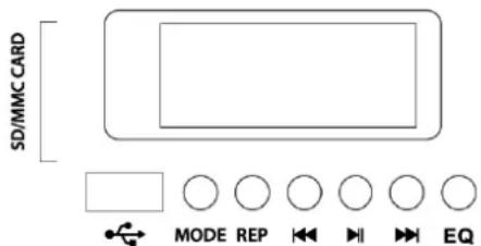
The A4 amplifier is equipped with a multi-functional media player for playback of audio files from USB or SD media, FM radio stations or Bluetooth connection. Front panel controls are as described below.
| MODE | Select between USB, SD, FM tuner & Bluetooth |
| REP | Repeat mode – Random, One, Folder and All |
| ◀◀ | Previous track/FM station (hold for volume down) |
| ▶ II | Play/Pause (Auto-tune in FM mode) |
| ▶▶ | Next track/FM station (hold for volume up) |
| EQ | Select preset - Bass/Pop/Rock/Jazz/Classical/Normal |
text_image
SD/MMC CARD MODE REP EQUSB/SD media playback
Insert USB or SD media containing mp3 tracks and playback should begin automatically.
The stored tracks should be standard mp3 audio format. If playback does not start, press MODE or ▶ II
The display will initially show the track number and then an elapsed time counter.
A USB or SD symbol will also be displayed to show which media is being used.
Ensure MEDIA PLAYER is selected on the output selector (9) and turn up the MEDIA volume control (6)
Tracks may be navigated by pressing ◀◀ for the previous track and ▶▶ for the next track.
Press and hold ◀◀ to reduce the media player volume or press and hold ▶◀ to increase the volume.
Playback can be paused and resumed by pressing ▶ II
Pressing REP sets the repeat mode: rR = random, = single track, FOLd = folder, RLL = all tracks
Pressing EQ sets the preset: bAS = bass, POP = pop, rOC = rock, UAC = jazz, CLA = classical, rOR = normal
FM Tuner
The FM tuner function operates in the same way as a standard FM radio and benefits from the connection of an FM antenna to the rear panel 'F' type connector.
Press the media player MODE button until the display shows a frequency (e.g. "88.3MHz")
If auto-tuning has already been performed, the display may show a channel (e.g. "CH0 I")
If no channels are tuned in, press the ▶ II button to begin auto tuning, which scans available stations and stores them as channels within the FM tuner. Pressing ▶ II again will abort the auto-tuning.
To step through pre-set stations, press the ◀◀ or ▶▶ buttons... [CH01 - CH02 - CH03 - CH04 etc.
Press and hold ◀◀ to reduce the FM radio volume or press and hold ▶▶ to increase the volume.
Bluetooth
The Bluetooth function allows connection of a smart phone or tablet to the media player section for playback of stored files or streamed digital audio. To enable this function, it will be necessary to pair the sending device to the receiver as follows.
- Press the media player MODE button until the display flashes "BLUE"
- Open the Bluetooth settings menu on the smart phone or tablet (or other sending device)
- Scan for Bluetooth devices and look for "A series" in the list of available devices (ensure that the A4 is powered on, Bluetooth mode is selected and within reception range)
- Select "A series" and the sending device should confirm that it is connected as an audio device.
- Play audio from the sending device, ensuring that volume controls are not turned down/muted
- Select MEDIA PLAYER input (9) and turn up the MEDIA volume control (6) to the required level.
The ◀◀, ▶▶ and ▶ II buttons will operate in Bluetooth as remote playback controls.
Holding the ◀◀ or ▶▶ buttons will adjust the output volume of the player.
If the sending device goes out of range, connection should automatically resume when back in range. Likewise, if a different mode is selected, connection should resume when Bluetooth mode is re-selected. If Bluetooth is disabled on the sending device or paired to a different receiver, it will be necessary to reconnect the sending device to the A4 from step 2 above to re-establish a Bluetooth link.
Media player remote control
In addition to front panel controls, the media player can be operated via the supplied I.R. remote handset.
As supplied, the handset will have a plastic tab at the bottom to preserve battery charge before first usage. Remove this tab by pulling away from the handset to engage the battery and activate the remote control. If this needs to be replaced, the battery compartment can be slid out from the bottom to reveal the cell. Replace the battery with a CR2025 button cell.
Point the top of the remote control towards the media player display and operate in line of sight.
Some of the controls on the remote handset mirror those on the front panel and are described below.
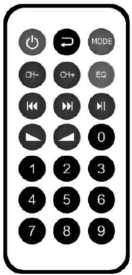
text_image
MODE CH- CH+ EQ 0 1 2 3 4 5 6 7 8 9| Media player power on/standby button | |
| Repeat mode – select Random, One, Folder or All tracks | |
| MODE | Select USB, SD, FM tuner or Bluetooth mode |
| CH- / CH+ | Select FM radio station |
| EQ | Select preset EQ – Bass, Pop, Rock, Jazz, Classical or Normal |
| |◀ / ▶| | Previous or Next track select |
| ▶ II | Play / Pause track (auto-tune in FM tuner mode) |
| ▲ / ▲ | Adjust media player volume down or up |
| 0 - 9 | Direct track or channel access – key in number |
Specifications
| Power supply | 230Vac, 50Hz (IEC) |
| Power consumption max. | 360W |
| Fuse | F5A, 250V |
| Output power rms @ 4 Ohms | 4 x 200W |
| Output power rms @ 8 Ohms | 4 x 100W |
| Amplifier: construction | Class D |
| Frequency response | 20Hz - 20kHz ±0.5dB |
| Microphone inputs | 2 x 6.3mm jack (mono) |
| Line inputs | Line 1: L+R (6.3mm jack/RCA), Line 2: L+R (RCA), Aux (3.5mm stereo) |
| Input sensitivity: line | 0.775Vrms |
| Input sensitivity: aux | 0.480Vrms |
| Input impedance | 20k Ohms (balanced), 10k Ohms (unbalanced) |
| Audio source | USB/SD mp3 playback, FM tuner, BT receiver |
| Input controls | Aux, Media, Line1, Line2, Mic1, Mic2, Talkover |
| Line output | 4 x RCA |
| Speaker outputs | 4mm binding posts (4 channels) |
| Antenna connection | F type (FM tuner) |
| Output controls | 2 x Source select, 2 x Bass, 2 x Treble, Ch1, Ch2, Ch3, Ch4 |
| Dynamic range | 92dB |
| THD +N | <0.1% |
| Protection | Thermal, over-current, over-voltage, short-circuit |
| Dimensions | 482 x 260 x 88mm |
| Weight | 5.98kg |
Troubleshooting
| No power LED on control panel | Ensure IEC lead is in good condition and connected properly |
| Ensure POWER switch is on and check mains inlet fuse | |
| Power light and output LEDs lighting but no output | Check speaker output terminals are connected correctly |
| Check speakers are working (test on another amp if available) | |
| Check memory device is connected properly (remove and re-insert) | |
| Check file types – standard mp3 digital audio files required | |
| Check memory device works on a PC or Mac for standard playback | |
| Bluetooth cannot connect | Ensure that Bluetooth is enabled on sending device |
| Ensure that the sending device is within Bluetooth range (5-10m) | |
| Check that the device is connecting to "A series" | |
| No audio from Bluetooth device | Ensure that volume controls are not turned down on sending device |
| Check volume and Play/Pause buttons on media player | |
| Output too loud or distorted | Reduce MIC, LINE IN, USB/SD and/or MASTER level |
| Ensure Hi-Z line level input(s) not connected to a Mic input | |
| Output too quiet or inaudible | Increase MIC, LINE IN, USB/SD and/or MASTER level |
| Check for quiet recording of media files on USB | |
| Check VOX override is not unintentionally suppressing audio playback | |
| Feedback from microphone | Face microphone away from speakers and monitors and reduce level |
| Amplifier overheating | Ensure cooling vents are clear from debris and dust |
| Ensure that the load impedance on any output channel is no less than 4Ω |



Disposal: The "Crossed Wheelie Bin" symbol on the product means that the product is classed as Electrical or Electronic equipment and should not be disposed with other household or commercial waste at the end of its useful life. The goods must be disposed of according to your local council guidelines.
Hereby, AVSL Group Ltd. declares that the radio equipment type 953.404UK is in compliance with Directive 2014/53/EU
The full text of the EU declaration of conformity for 953.404UK is available at the following internet address:
http://www.avsl.com/assets/exportdoc/9/5/953404UK%20CE.pdf
Errors and omissions excepted. Copyright© 2022.
AVSL Group Ltd. Unit 2-4 Bridgewater Park, Taylor Rd. Manchester. M41 7JQ
AVSL (EUROPE) Ltd, Unit 3D North Point House, North Point Business Park, New Mallow Road, Cork, Ireland