
XLE070 - Heating DIMPLEX - Free user manual and instructions
Find the device manual for free XLE070 DIMPLEX in PDF.


| Product Type | Electric Radiator |
| Brand | Dimplex |
| Model | XLE070 |
| Power Rating | 700 W |
| Voltage | 230 V ~ 50 Hz |
| Dimensions (H x W x D) | 450 mm x 600 mm x 100 mm |
| Weight | 5 kg |
| Heating Element | Convection |
| Thermostat | Adjustable, with frost protection |
| Timer | 24-hour programmable |
| Installation | Wall-mounted or free-standing |
| Safety Features | Overheat protection, tip-over switch |
| Energy Class | A |
| Noise Level | < 25 dB |
| Material | Steel body |
| Color | White |
| Cleaning | Wipe with a damp cloth, do not use abrasives |
| Spare Parts Availability | Through Dimplex service centers |
| Warranty | 2 years |
Frequently Asked Questions - XLE070 DIMPLEX
User questions about XLE070 DIMPLEX
0 question about this device. Answer the ones you know or ask your own.
Ask a new question about this device
Download the instructions for your Heating in PDF format for free! Find your manual XLE070 - DIMPLEX and take your electronic device back in hand. On this page are published all the documents necessary for the use of your device. XLE070 by DIMPLEX.
USER MANUAL XLE070 DIMPLEX
Installation and Operating
natural_image
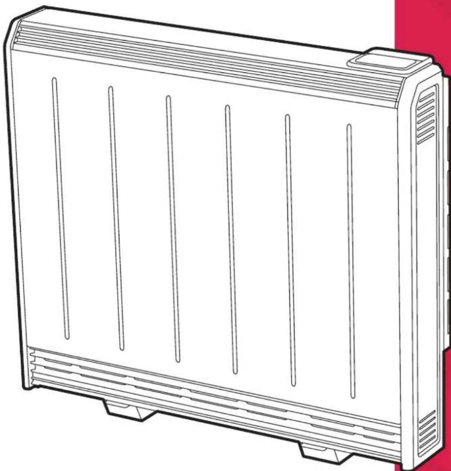
Line drawing of a rectangular electronic device with five vertical slots, no text or symbols presentDimplex XLE Series Heater
Models: XLE050 / XLE070 / XLE100
XLE125 / XLE150
These instructions should be read carefully and retained for future use. Note also the information presented on the appliance.
CAUTION
FAILURE TO FOLLOW THESE INSTRUCTIONS MAY CAUSE INJURY AND/OR DAMAGE AND MAY INVALIDATE YOUR GUARANTEE
IMPORTANT SAFETY ADVICE
When using electrical heaters, basic precautions should always be followed to reduce the risk of fire, electrical shock, and injury to persons, including the following:
IMPORTANT - The wall bracket supplied with the heater must be used.
IMPORTANT - All packaging should be disposed of in an appropriate manner.
OVERHEATING WARNING
WARNING - In order to avoid overheating, do not cover or obstruct the heater. Do not place material or garments on the heater, or obstruct the air circulation around the heater, for instance by curtains or furniture, as this could cause overheating and a fire risk. NEVER cover or obstruct in any way the heat outlet slots at the top of the heater or the air outlet slots in the base of the heater.
WARNING - THE SURFACES ON THIS HEATER CAN BE HOT.
The heater carries a warning 'DO NOT COVER' to alert the user to the risk of fire that exists if the heater is accidentally covered.

CAUTION - Some parts of this product can become very hot and cause burns. Particular attention has to be given where children and vulnerable people are present.
For your safety this heater is fitted with a thermal cut-out. In the event that the product overheats for some reason, the cut-out prevents excessive temperatures on the product by cutting the power to the heater. Once the heater has cooled down, it will reset automatically, it will continue to cycle on and off automatically until the reason for overheating is removed.
The display screen may flash red to indicate the product has overheated. To reset the display, remove the obstruction and hold Enter for 10 seconds.
SUITABLE APPLICATIONS
WARNING - This heater is suitable for normal domestic household purposes and should not be used in any other type of environment. This product should only be used in the country where it was purchased from by a recognised commercial retailer. Do not use outdoors.
SERVICING AND REPAIRS
WARNING - Servicing and product repairs should only be undertaken by the manufacturers approved service agent or a similarly trained or qualified person, using only exact manufacturer approved spare parts.
PLEASE NOTE: Household dust, lit cigarettes, candles and oil burners, combined with the convection effect of electric heaters can cause significant soot deposits to build up on the surface directly above and to the sides of the heater. This is not a fault of the heater. Extensive burning of candles or smoking in the operating environment of this product can produce heavy discolouration within a few months of use.
OPERATING WARNINGS
IMPORTANT: Remember to observe all safety warnings and precautions when operating the heater on the automatic or timer modes, either attended or unattended since a fire risk exists when the heater is accidentally covered or obstructed.
Mains cables are not provided with this heater.
CAUTION: Do not use if either of the heater's mains power leads become damaged. If the supply cord is damaged it must be replaced by the installer or an approved Dimplex service partner.
Curtains must not come to within 250mm of the top of the heater.
Do not sit or stand on the heater.
Do not place objects in contact with the heater.
To maintain stability, it is essential that the heater is placed on a level surface and care should be taken to avoid irregular surfaces, such as may result from carpets or tiled surrounds partially protruding under the heater.
ELECTRICAL INSTALLATION
The installation of the heater should be carried out by trained personnel.
WARNING - Minimum clearances and IP zone requirements must be adhered to in accordance with the current wiring regulations.
WARNING - The electrical installation of this heater must be carried out by a suitably qualified or trained electrician, and be in strict accordance with current wiring Regulations. The peak supply must be connected via a switched fused spur with a fuse rated suitably for the appliances flex, the off-peak supply, via a 20A double pole switch. Failure to follow these instructions will mean that the manufacturer's instructions have not been adhered to. THERE ARE NO EXCEPTIONS.
• This heater must be earthed
- Not suitable for connection via a plug top
- Do not locate the heater immediately above or below a fixed electrical point i.e. socket outlet.
This appliance is intended for installation to a single phase supply only and is not suitable for connection to 3 phase supplies.
The heater is not fitted with a mains cable, this should be fitted by the installer. Cable type (minimum size) H05VV-F 1.5mm ^2 three core for peak and 2.5mm ^2 three core for off-peak for connection to the fixed wiring of the premises through suitable isolation devices positioned adjacent to the heater. The supply circuits to the heater must incorporate a double pole isolating switch having a contact separation of at least 3mm.
In installation the supply cord must be cut to the appropriate length for the electrical connection point. Excess cable should not be inserted or stored behind the heater.
If, during reassembly of the heater, a part of the thermal insulation shows damage or deterioration, it should be replaced by an identical part.
WARNING: All electrical connections to the terminal block must be secure to prevent risk of ignition. Tighten to 0.5 Nm.
CHILD SAFETY
WARNING - Fixing kit screws are a potential choking hazard.
WARNING - This appliance is not intended for use by persons (including children) with reduced physical, sensory or mental capabilities, or lack of experience and knowledge, unless they have been given supervision or instruction concerning use of appliance by a person responsible for their safety.
This appliance can be used by children from 8 years and above and persons with reduced physical, sensory or mental capabilities or lack of experience and knowledge if they have been given supervision or instruction concerning use of the appliance. Children shall not play with the appliance. Cleaning and user maintenance shall not be made by children without supervision.
Children of less than 3 years should be kept away unless continuously supervised. Children aged from 3 years and less than 8 years shall only switch on/off the appliance provided that it has been placed or installed in its intended normal operating position and they have been given supervision or instruction concerning use of the appliance in a safe way and understand the hazards involved. Children aged from 3 years and less than 8 years shall not regulate and clean the appliance or perform user maintenance.
Technical Details
| Models XLE050 XLE070 XLE100 XLE125 XLE150 | |||||
| Nominal Output (kW) 0.50 0.75 1.00 1.25 1.50 | |||||
| Storage Element Rating 230/240V-: | 936/1020W 1435/1560W 2042/2220W 2540/2760W 3024/3300W | ||||
| Boost Output 230/240V-: | 312/340W | 479/520W | 681/740W | 847/920W | 1008/1100W |
| Rated Charge Period: | 7.7 - 7 Hours | 7.7 - 7 Hours | 7.7 - 7 Hours | 7.7 - 7 Hours | 7.7 - 7 Hours |
| kWh: | 7.14kWh | 10.9kWh | 15.5kWh | 19.3kWh | 23.1kWh |
| Fan Wattage | 11W | 11W | 11W | 11W | 11W |
| UI Wattage | 0.5W | 0.5W | 0.5W | 0.5W | 0.5W |
| Sound Level dB (measured in test chamber) | 27 | 29 | 32 | 30 | 31 |
| Energy Cell Packs Required (047243) | 4 | 6 | 8 | 10 | 12 |
| Installed Weight: | 63kg | 85kg | 107kg | 133kg | 155kg |
| Height (mm) | 749 | 749 | 749 | 749 | 749 |
| Width (mm) | 581 | 703 | 825 | 947 | 1069 |
| Depth (mm) | 182 | 182 | 182 | 182 | 182 |
| All Models | |
| Controls | Digitally controlled, Electronic Thermostat accurate to (±0.2°C). Setpoint range (7-26°C)Timer modes:7 Day Programmable User Timer, Out All Day, HolidayContinuous heat modes:Setback |
| Controller UI | Graphical display with RGB backlightCapacitive buttons with audio feedbackUser replaceable battery (Coin-Type) |
| Controller Functions | Open window detectionAutomatic Charge ControlBluetooth for software updatesChild Lock |
| Safety Features | Electronic overheat protection. Additional electromechanical overheat protection.LVD and EMC compliance. |
| Storage Core | High-density bonded magnetite energy cells |
| Colour/Finish | White (RAL 9016) 'Traffic White'. Grill RAL7035 anodised |
| Battery Backup | 3.3V coin cell battery to backup real time clock. Battery life >5 years. |
| Supply (each) | 1/N/PE 230-240V / 50Hz (Peak / Off Peak) Class II |
| IP Rating | IPX4 |
| Approvals | CE & BEAB |
| Warranty | 2 Years |
| Country of Origin | United Kingdom |
| Manufacturer | Glen Dimplex Heating & Ventilation (GDC Group Ltd.) |
Preparation
- Place the heater within its packaging flat on the ground with arrows printed on the base of the carton pointing upwards.
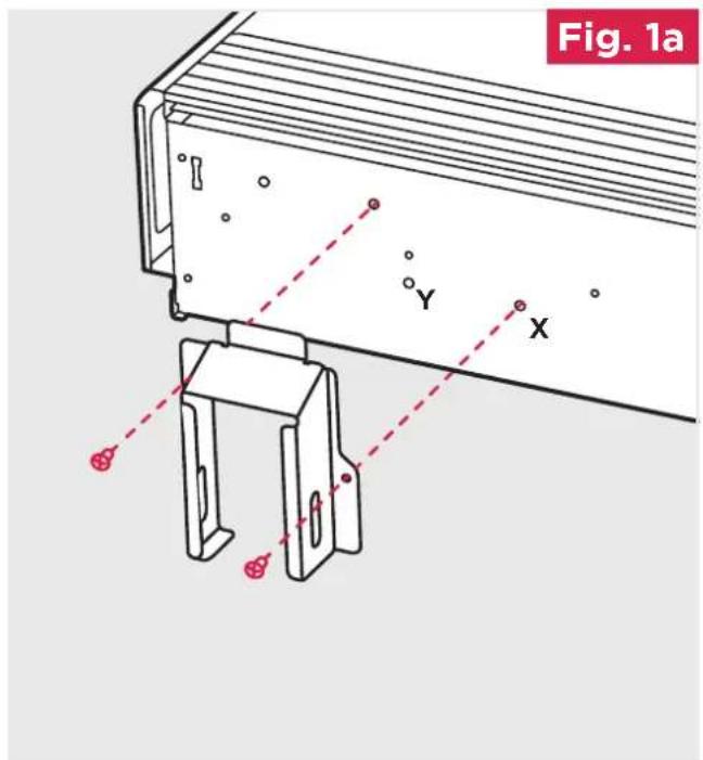
- Feet are fitted in the default position (X position) and can be moved to the outside position (Y position) if necessary. (Fig. 1a and Fig. 1b). NB: Repositioning of feet may be required depending on floor arrangement (e.g. replacing an installation).
Stand the heater on its feet before removing the packaging.
CAUTION SHOULD BE TAKEN NOT TO REST THE HEATER UPON THE ROOM TEMPERATURE SENSOR HOUSING. (Fig. 1b)
Dispose of packaging in an appropriate way. Read these instructions carefully before proceeding any further with the installation.
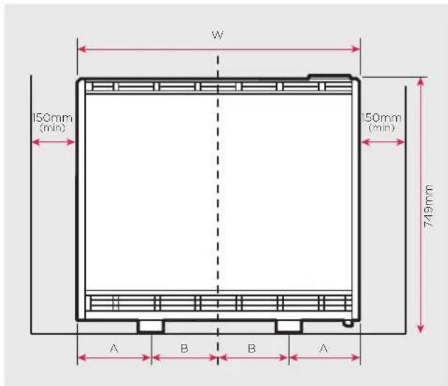
text_image
W 150mm (min) 150mm (min) 749mm A B B A| Models 050 | 070 100 | 125 150 | |||
| Feet Position1 'A/B' | 167/124 | 167/185 167 | /246 160 | /314 160 | /375 |
| Feet Position2 'A/B' | 93/198 | 93/259 93/ | 320 100/ | 374 100/ | 435 |
- Ensure the heater is stable before removing the screws which hold the bottom grille panel in position. (Fig. 2) Set the bottom grille to one side, avoiding its sharp edges when handling.
- Remove the two screws securing the front panel, located at the bottom of the heater (Fig. 3). Once removed set carefully to one side to avoid damage.
NOTE - Retain these screws for reassembly. If misplaced, M4 x 10 Tritap screws must be used. IMPORTANT - Do not use the outer top panel or the rear heat shield to lift or carry the heater.
text_image
Fig. 1a Y X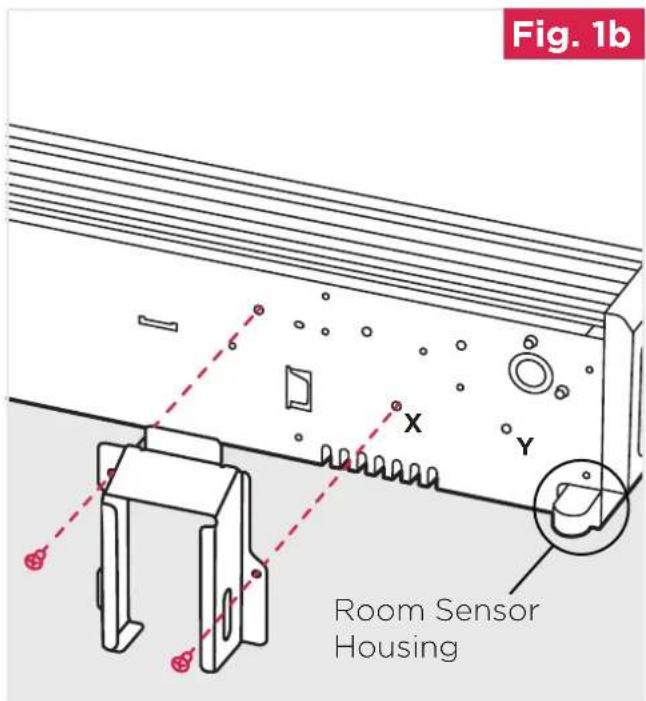
text_image
Fig. 1b Room Sensor Housing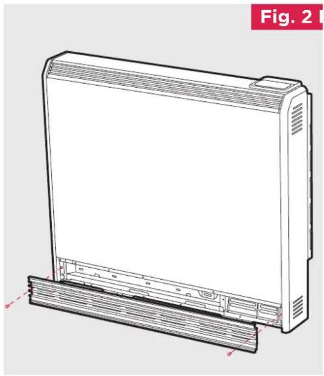
natural_image
Technical line drawing of a rectangular electronic device with a side panel and mounting base (no text or symbols)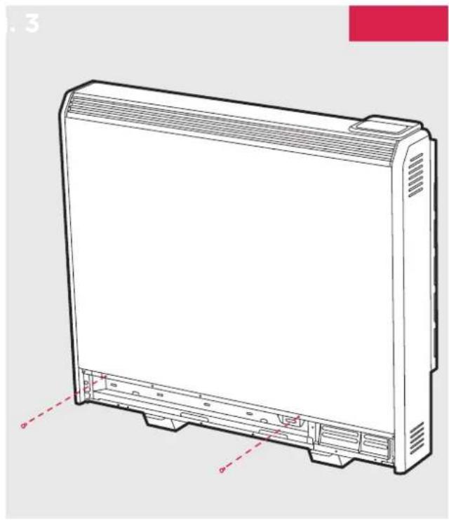
natural_image
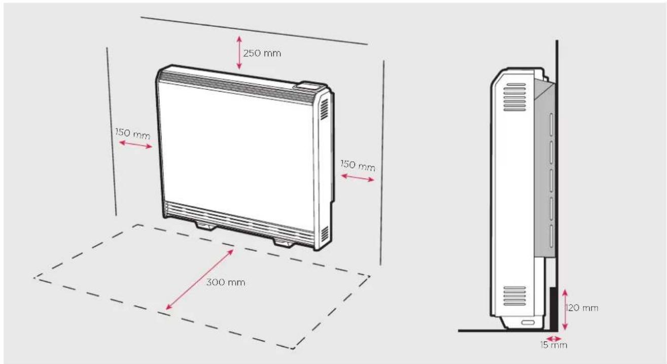
Line drawing of a rectangular electronic device with front panel and side connectors (no text or symbols)Ensure the back of the heater is flush against the wall. If the skirting board is taller than 120mm and deeper than 15mm it should be cut to accommodate safe installation of the heater.
Do not place objects within 300mm of the front of the heater and 150mm either side.
text_image
250 mm 150 mm 150 mm 300 mm 120 mm 15 mmInstalling the Heater
IMPORTANT Head of wall fixing screw must be flanged pan head type and have a diameter no less than 11mm. No countersunk headed screws to be used for wall fixing.
The heater must be securely fixed to a wall. Screws with suitable wall fixings for solid walls are provided. If other wall types are encountered it is the installer who must choose the most suitable fixing.
SUGGESTED FIXINGS
SOLID BRICK/BLOCK: No. 10 size high temperature resistant plastic inserts, 8mm drill bit. Drill hole 15mm deeper than plastic insert length.
PLASTERBOARD - If possible locate studding and use No. 10 woodscrews directly into the wood, otherwise M5 rawlplug intersets are suitable.
NOTE: FOR OTHER WALL TYPES (eg. timber frame and hollow concrete) SEEK SPECIALIST ADVICE.
If the floor is carpeted then the carpet should be slit and underlay cut away to allow the feet to rest firmly on the floor. Carpet gripper must be locally removed so that the feet may rest in a level position.
This appliance is heavy. The floor must be checked to ensure that it is capable of bearing the weight of the unit, up to 165kg.
This Heater is rated IPX4

DO NOT UNDER ANY CIRCUMSTANCES ATTEMPT TO MOVE OR REPOSITION THIS HEATER WITHOUT SEEKING EXPERT ADVICE. THE HEATER SHOULD NEVER BE FREED FROM THE WALL WITH ENERGY CELLS INSIDE.

USE CAUTION WHEN INSTALLING THIS PRODUCT, UNPAINTED METALWORK CAN HAVE SHARP EDGES.
natural_image
Technical diagram of a mechanical assembly with circular components and two red hotspots (no text or symbols)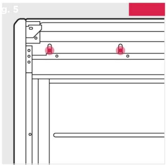
natural_image
Technical line drawing of a mechanical assembly with two red lock icons on a panel (no text or symbols)NOTE: ANY FIXING DROPPED INTO HEATER MUST BE RETrieved AS THEY MAY IMPACT PRODUCT SAFETY DURING OPERATION.
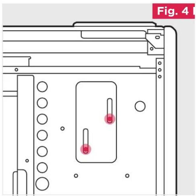
- Place the heater in its final position and mark the fixing holes through the location holes visible through the back of the heater.
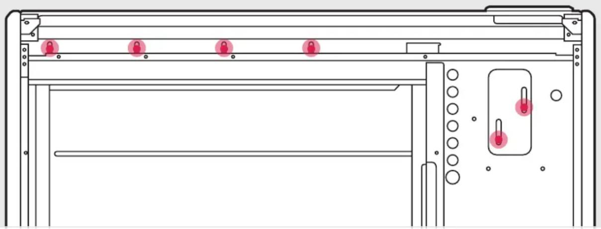
- Six fixing positions must be selected for models XLE100, XLE125, XLE150 and at least 4 fixing positions for models XLE050 and XLE070. Fig. 6.
Common fixing points for all heater sizes are shown in both Fig. 4 and Fig. 5.
Mark the positions for the fixing holes towards the bottom of each slot, this allows the heater to settle once the energy cells have been fitted.
Move the heater away from the wall, drill the holes and fit the wall fixings best suited to the application.
Secure the heater to the wall using correct quantity of screws required per model, using the appropriate screw fittings.
NB: Do not fully tighten screws until energy cells are fully loaded to ensure full weight is on feet and not on the wall fixings.
NOTE: UNDER NO CIRCUMSTANCES SHOULD ANY SCREWS BE REMOVED WITHOUT FIRST REMOVING ALL ENERGY CELLS FROM THE HEATER.
NEVER FREE THE HEATER FROM THE WALL WITH ENERGY CELLS REMAINING INSIDE THE HEATER CAVITY.
Fig. 6
natural_image
Technical line drawing of a door frame with five red lock icons and a close-up view of the door (no text or symbols)Warning: Before obtaining access to terminals, all supply circuits must be disconnected.
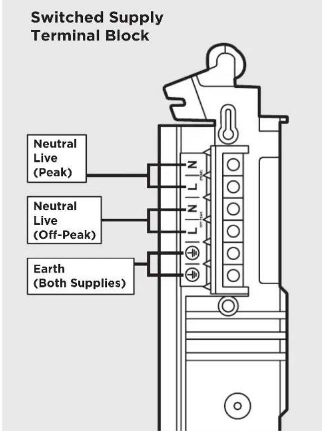
- The heater leaves the factory configured to operate with two mains supplies, a 24 hour peak supply and an off peak switched supply. (Fig. 7)
Not suitable for use on single supply.
Storage / Fan circuit
Fan Circuit = PEAK L
Storage Circuit = OFF-PEAK L
Fan Circuit = PEAK N
Storage Circuit = OFF-PEAK N
The earth wire should be connected into the earth terminal block marked E
WARNING: Terminal block maximum torque 0.5 Nm
Fig. 7
text_image
Switched Supply Terminal Block Neutral Live (Peak) Neutral Live (Off-Peak) Earth (Both Supplies)
text_image
Mains Cable Tighten Screws- The mains cable entry and terminal block will be visible on the right hand side of the unit. Insert the mains cables through the cable gland at the bottom of the heater in readiness for connection (Fig. 8).
IMPORTANT: Only heat resistant ordinary polyvinyl chloride sheathed flexible cord should be used, the following codes apply;
IEC: 60227 IEC57 or CENELEC: H05V2V2-F
Maximum Cable Sizes
Peak mains cable 1.5mm ^4
Off-peak mains cable 2.5mm ^4
WARNING: Maximum torque 0.5 Nm
WARNING: All electrical connections to the terminal block must be secure to prevent risk of ignition.
text_image
Fig. 9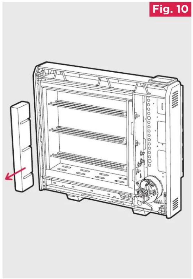
natural_image
Technical line drawing of a device casing with internal components and a red arrow indicating a directional change (no text or symbols)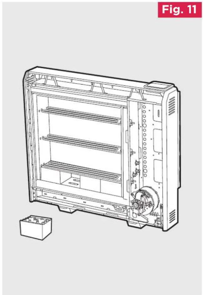
natural_image
Technical line drawing of an internal storage unit with visible internal compartments and a base housing (no text or symbols)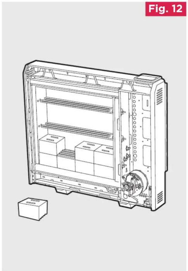
natural_image
Technical line drawing of a mechanical device with internal compartments and housing (no text or symbols)Building the Heater Core
-
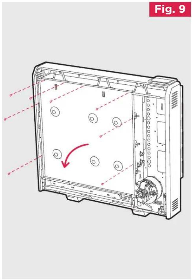
Remove the inner front and insulation to gain access to the core of the heater. Lay the inner front carefully to one side to ensure it is not damaged. (Fig. 9)
-
Remove the cardboard element support and dispose of. (Fig. 10)
Energy Cells
The energy cells are supplied separately to the heater in packs of three. The reference number is 047243.
Energy Cells should be handled with care due to the weight and risk of hand/foot injury.

- The energy cells have several grooves on one surface for locating around the elements. The two slots through the centre of the energy cell create the air passages within the core.
Position the first energy cell of the bottom row to the right, firmly pressed against the side insulation with the element grooves facing upwards and fitting neatly around the element. Angle the element upward to fit the energy cell.
Position the second energy cell in the row against the left-hand insulation. Place the remaining energy cells between the first and second in the row. (Fig. 11)
DO NOT DISCONNECT THE ELEMENT TERMINALS
In addition ensure the slots for the air passages line up with the holes in the base insulation.

NOTE:
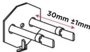
The element tails must extend no further than 30mm into the right hand chamber.
text_image
30mm ±1mmFit the remaining energy cells to the bottom row, being careful not to damage or dislodge the element.
Note - The bends in the element locate around the grooves in the energy cell to secure the element.
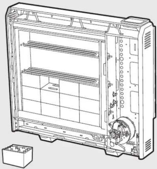
- Position the second row of energy cells on top of the first but this time the energy cells must be upside down ensuring the grooves are positioned over the elements. (Fig. 12)
Fig. 13
Fig. 14
natural_image
Technical line drawing of a server rack unit with internal compartments and mounting base (no text or symbols)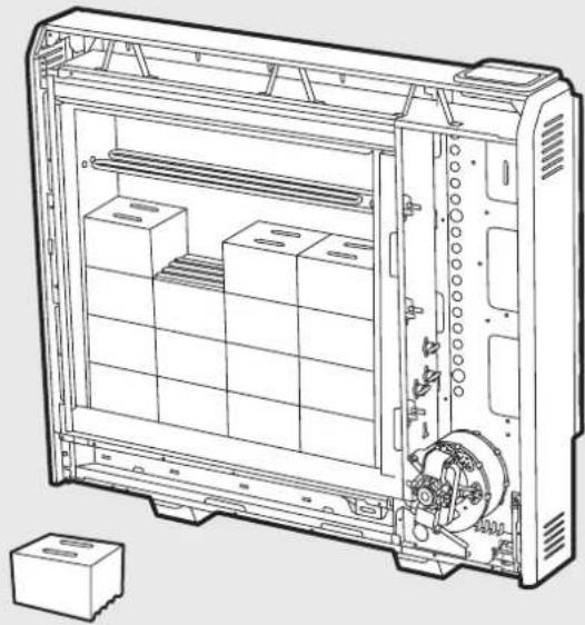
natural_image
Technical line drawing of a mechanical device with internal compartments and housing (no text or symbols)Fig. 16
Fig. 15
natural_image
Technical line drawing of a rectangular electronic device with internal compartments and mounting base (no text or symbols)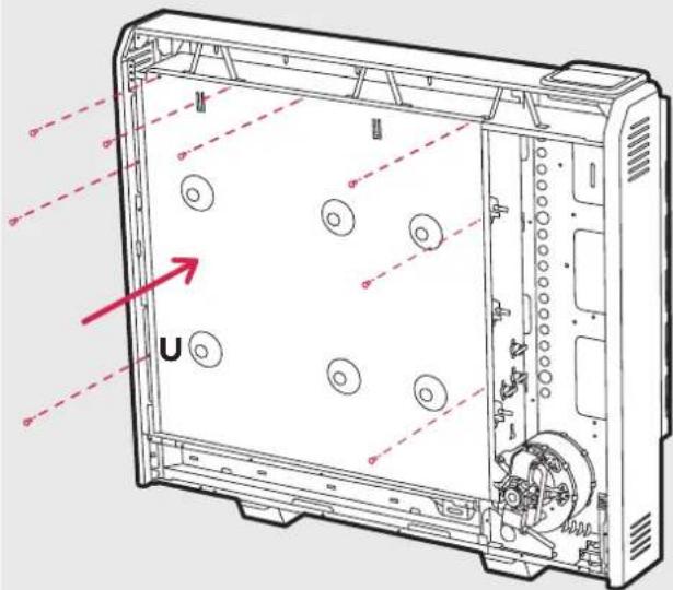
text_image
Technical diagram of a computer chassis with labeled components and directional arrows indicating movement or orientation.- The third row of energy cells is positioned in a manner similar to the first row. Again be careful not to damage or dislodge the element. (Fig. 13)
-
Fit the fourth row of energy cells above the third row in the upside position. Again, the first energy cell should be positioned firmly against the right-hand insulation, and the second energy cell should be positioned firmly against the left-hand insulation. (Fig. 14). Repeat for the fifth and sixth rows of energy cells built around the third element to complete the core build.
-
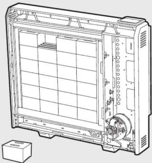
Remember the top row of energy cells must be fitted upside down. (Fig. 15)
Check that all the energy cells are secure and evenly located.
- Close the core by refitting the inner front panel complete with insulation, starting at position 'U' and working clockwise. (Fig. 16)
Ensure the bottom tabs are located inside the chassis and that the screws are tightly secured down each edge.
Ensure the screws retaining the heater to the wall are fully tightened, once the energy retention cells are fully loaded. (Fig. 6)

IMPORTANT
Double check all mains connections are secure and excess cable is restrained and not in contact with any of the heater casing.
ON NO ACCOUNT SHOULD ANY SURPLUS CABLE BE PUSHED INSIDE OR BEHIND THE HEATER.
Once installed DO NOT attempt to reposition the heater without first unloading the energy cells.
Reassembly
To replace the bottom grille and front panel, reverse steps 3 and 4 of these instructions under the section headed Preparation.
Inspect the grille guard for damage before refitting the lower grille to the heater.
Ensure all fixings are secure.
Operation
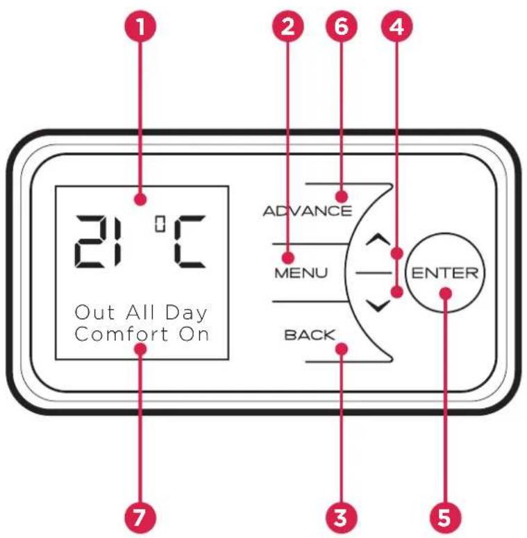
The controls are located on the top of the heater. The heater is fitted with an adjustable electronic controller consisting of a display screen and six touch sensitive buttons.
1 Display Screen
2 'Menu' Button
3 'Back' Button
4 'Up and Down' Arrows
5 'Enter' Button
6 'Advance' Button
7 Heating Status
text_image
1 2 6 4 3 5 7 Out All Day Comfort On ADVANCE MENU BACK ENTERThe heater is fitted with an adjustable thermostat enabling the room temperature to be controlled. The minimum room temperature is 7^ C. The maximum temperature is set to 26^ C. A temperature of 21^ C represents a normal room temperature.

NOTE:
Your heater may produce some noise during operation. This noise is caused by the low noise fan and expansion and contraction of the metalwork as it changes temperature, and is normal for this type of product. Whilst the noise produced is usually very quiet, certain environmental factors can make it more noticeable, such as hard flooring or minimal furnishings.

NOTE:
Should the heater fail to operate, this may be due to the room temperature being higher than the thermostat setting.
Control Functions
The heater controls can be easily adjusted by using the six buttons on the User Interface.
1 The Display Screen shows the options available at each stage of adjustment.
2 Menu - displays the main options list;
- Date/Time - Set the date and time.
- Mode - Set the mode of operation.
-Options - Keypad sound, daylight savings time, communication settings and service information.
3 Back returns to the previous programming stage.
4 The ∧ and ∨ buttons are used to navigate through the menus and alter setting values. The ∧ and ∨ buttons are also used to adjust the required room temperature on the main screen. The screen colour changes based on the temperature selected, showing deep blue through to bright red.
5 Enter is used within the menu options to confirm settings. On the main screen pressing Enter will display the enabled features.
The timed periods during which the heater is providing heat are defined as 'Comfort On' (this is displayed at the bottom of the screen).
Outside of heating periods the heater will not deliver heat and these periods are called 'Comfort Off'.
While constant heat modes are active, the mode of operation is displayed at the bottom of the screen e.g. 'Out All Day'.
6 The Advance button overrides the heating settings and changes the operational state of the heater. Pressing Advance will cause the heater to remain on until the next Comfort Off period is due, or off until the next Comfort On period is due.
Main Screen
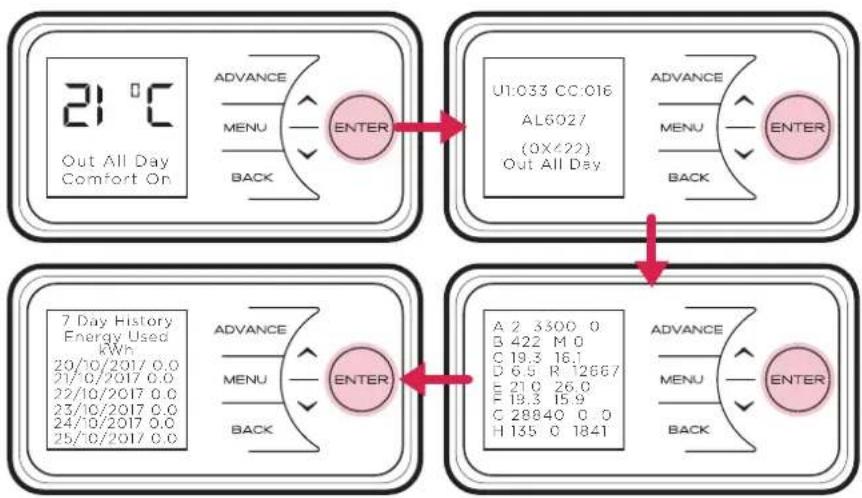
After 30 seconds the heater will default back to the Main Screen. Here the chosen temperature is displayed along with the mode of operation. Any use of the Advance, Boost, Setback function will be displayed here, and pressing Enter will show engineer's diagnostics and 7 day history screens.
When left inactive for a long period of time this display will 'sleep' and the text will disappear. Press any button for its return.
flowchart
graph TD
    A["21 °C Out All Day Comfort On"] --> B["ADVANCE MENU BACK ENTER"]
    B --> C["U1:033 CC:016 AL6027 (0X/22) Out All Day"]
    C --> D["ADVANCE MENU BACK ENTER"]
    D --> E["A 2 3300 0 B 422 M 0 C 19.3 16.1 D 6.5 R 12667 E 21.0 26.0 F 19.3 15.9 C 28840 0 0 H 135 0 1841"]
    E --> F["7 Day History Energy Used kWh 20/10/2017 0.0 21/0/2017 0.0 22/10/2017 0.0 23/10/2017 0.0 24/10/2017 0.0 25/0/2017 0.0"]
    F --> G["ADVANCE MENU BACK ENTER"]
    G --> H["ADVANCE MENU BACK ENTER"]

NOTE:
The display screen will return to the main screen after a period of 30 seconds of inactivity.

NOTE:
Pressing enter will show the engineer's diagnostics and 7 day history screens. Ref: page 17.
Setting the Date and Time
The heater incorporates a real time clock with calendar function. The time clock has a battery backup that will keep the clock running in the event of a mains power outage.
To adjust the time or date follow the steps below.
Press the Menu button. Select Date/Time by pressing the Enter button. Press ∧ and √ to select the correct day of the month and press Enter to select.
Repeat this operation, until the date and time has been set, ensuring to press Enter to select. Press Back button to return to the Main Screen once Set has been displayed.

flowchart
graph TD
    A["21°C Out All Day Comfort On"] --> B["Main Menu Date/Time Mode Options"]
    B --> C["Date/Time THU 27/07/2017 07:12"]
    C --> D["Date/Time ✓ Set"]
    D --> E["ADVANCE MENU BACK ENTER"]
    E --> F["ADVANCE MENU BACK ENTER"]
    F --> G["ADVANCE MENU BACK ENTER"]
Modes of Operation
The heater comes pre-programmed with a set of heating profiles. There are three options available - two pre-programmed and one user adjustable timer;
- User Timer (pre-programmed, factory default) - provides greatest flexibility to the user. Four time slots are available throughout the day and these can be customised for each day of the week. Factory default times: 06.30 until 09.30, 11.00 until 13.00, 15.00 until 17.00, 18.00 until 22.00.
- Out All Day (pre-programmed) - has the following preset times Monday to Sunday, which can be altered if desired 07.00 until 08.30 17.00 until 22.00, (factory default times).
- Holiday - set the date of return and the temperature required. 7°C is advised if you just want to protect the property from frost while you are away.
The heater can also maintain a constant room temperature using the following modes;
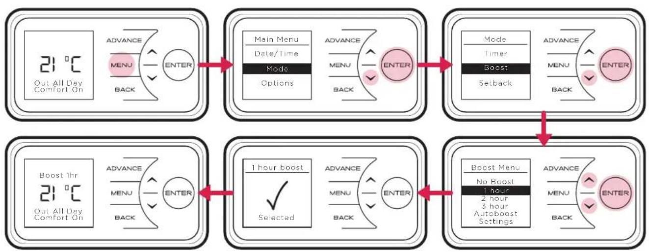
- Boost mode heats the room to a selected temperature for 1, 2 or 3 hours.
- Auto Boost Function maintains a room temperature during comfort periods, when the core is depleted.
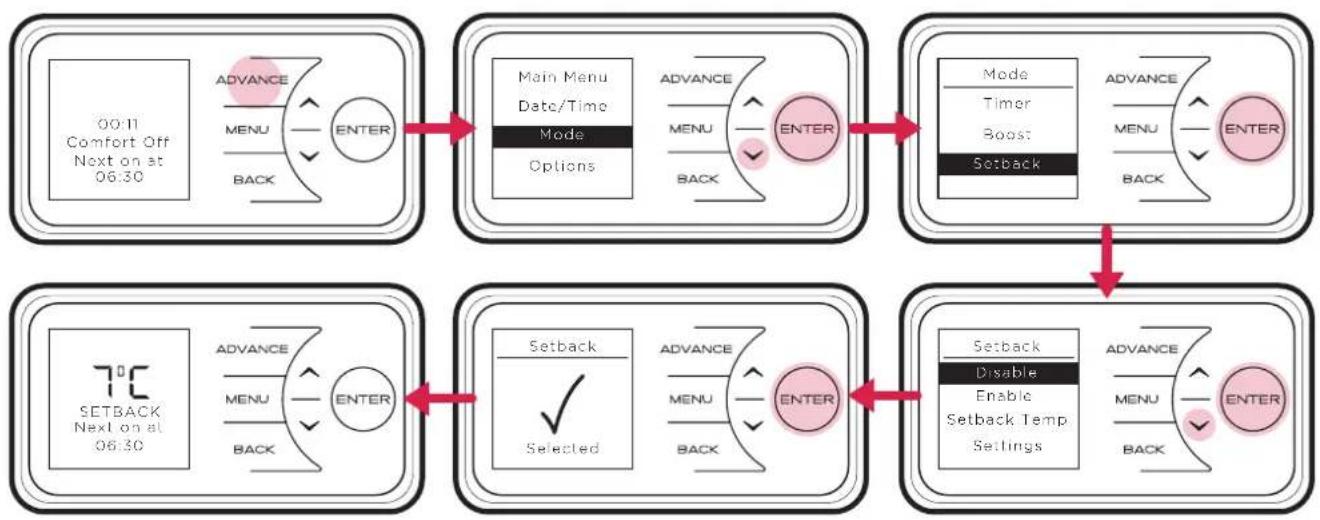
- Setback mode maintains a room temperature outside comfort periods. This mode should be used to provide protection against frost or where big drops in temperature are unwanted.

NOTE:
In all modes, except holiday mode, and can be used to adjust the required room temperature.

NOTE:
It is recommended that the timer is used as doing so can reduce the running cost. Operating the appliance in the permanent heating modes as Boost, Auto Boost or Setback may result in increased running costs.
Choosing and Setting a Mode
Timer Modes
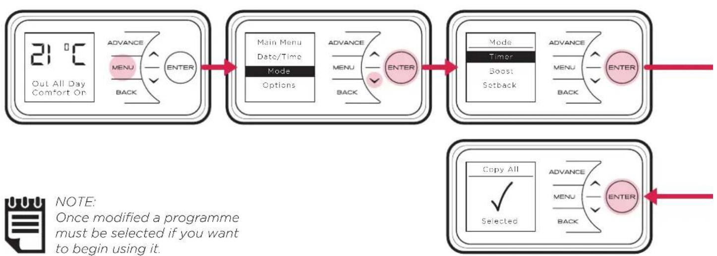
To choose a timer mode press Menu and then to select Mode. Then press Enter. Then select Timer Mode, again using the Enter button.
Select the mode required, by pressing the or followed by Enter.
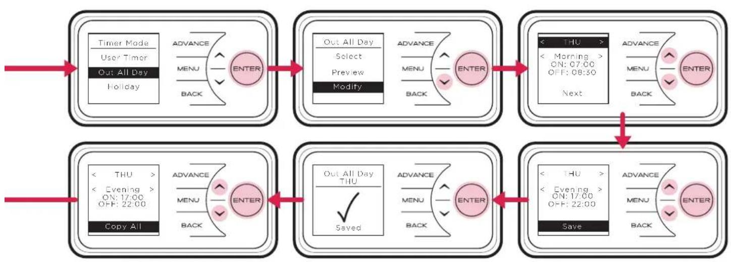
For options Out All Day, and User Timer, three choices are available - Select, Preview and Modify.
- Select - choose this timer option.
- Preview - view the times currently set.
- Modify - change the times currently set.
When Modify is chosen, select and change each option using the ∧, ∨ and Enter buttons. At the end of each period, select Next to move to the following period. When a day is complete select Save to update it.
Once the first day has been set up it is possible to copy these settings to successive days or all days by either choosing Copy Next or Copy All.
If preferred each day can be modified individually and saved. It is also possible to Clear each day or Clear All days to factory default times. Options are;
- Save - save times for one day.
• Copy Next - copy times to following day.
• Copy All - copy times to all seven days. - Clear - factory defaults all times that day.
- Clear All - factory default times for all seven days.
To select a mode, choose Select and press Enter.
flowchart
graph LR
    A["21 °C Out All Day Comfort On"] --> B["Main Menu Date/Time Mode Options"]
    B --> C["Mode Timer Boost Setback"]
    C --> D["Copy All Selected"]

    subgraph Program
        E["Advance MENU BACK"] --> F["ENTER"]
        G["Advance MENU BACK"] --> H["ENTER"]
        I["Advance MENU BACK"] --> J["ENTER"]
        K["Advance MENU BACK"] --> L["ENTER"]
        M["Advance MENU BACK"] --> N["ENTER"]
        O["Advance MENU BACK"] --> P["ENTER"]
        Q["Advance MENU BACK"] --> R["ENTER"]
        S["Advance MENU BACK"] --> T["ENTER"]
        U["Advance MENU BACK"] --> V["ENTER"]
        W["Advance MENU BACK"] --> X["ENTER"]
        Y["Advance MENU BACK"] --> Z["ENTER"]
        AA["Advance MENU BACK"] --> AB["ENTER"]
        AC["Advance MENU BACK"] --> AD["ENTER"]
        AE["Advance MENU BACK"] --> AF["ENTER"]
        AG["Advance MENU BACK"] --> AH["ENTER"]
        AI["Advance MENU BACK"] --> AJ["ENTER"]
        AK["Advance MENU BACK"] --> AL["ENTER"]
        AM["Advance MENU BACK"] --> AN["ENTER"]
        AO["Advance MENU BACK"] --> AP["ENTER"]
        AQ["Advance MENU BACK"] --> AR["ENTER"]
        AS["Advance MENU BACK"] --> AT["ENTER"]
        AU["Advance MENU BACK"] --> AV["ENTER"]
        AW["Advance MENU BACK"] --> AX["ENTER"]
        AY["Note: Once modified a programme must be selected if you want to begin using it."]
    end
In Holiday mode the date until the room will be unoccupied can be set/adjusted together with the required room temperature.
Press and to set the return date, then press the Enter button.
Press and to choose a temperature to be maintained during this period and press the Enter button. At the end of the holiday mode the heater will automatically revert back to the previously selected programme.
flowchart
graph TD
    A["Timer Mode\nUser Timer\nOut All Day\nHoliday"] --> B["ADVANCE\nMENU\nBACK"]
    B --> C["ENTER"]
    C --> D["Out All Day\nSelect\nPreview\nModify"]
    D --> E["ADVANCE\nMENU\nBACK"]
    E --> F["ENTER"]
    F --> G["< THU >\n< Morning >\nON: 07:00\nOFF: 08:30\nNext"]
    G --> H["ADVANCE\nMENU\nBACK"]
    H --> I["ENTER"]
    I --> J["< THU >\n< Evening >\nON: 17:00\nOFF: 22:00\nSave"]
    J --> K["ADVANCE\nMENU\nBACK"]
    K --> L["ENTER"]
    L --> M["< THU >\n< Evening >\nON: 17:00\nOFF: 22:00\nSave"]
Advance
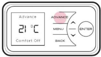
The Advance function allows the heating profile of the heater to be changed temporarily. When a timer has been selected, the Advance function is used to begin the next Comfort On mode early. If the heater is in Comfort Off mode and heat is required, press the Advance button.
If the heater is in Comfort On and heat is not required, press the Advance button and the heater will turn off until the beginning of the next Comfort On period.
text_image
Advance 21 °C Comfort Off ADVANCE MENU BACK ENTERBoost
Boost mode provides temporary heating for one, two or three hours. Auto Boost maintains a room temperature during Comfort On periods, when the core is depleted.
flowchart
graph TD
    A["21°C Out All Day Comfort On"] --> B["Main Menu Date/Time Mode Options"]
    B --> C["Mode Timer Boost Setback"]
    C --> D["Boost Menu No Boost 1 hour 2 hour 3 hour Autoboost Settings"]
    D --> E["1 hour boost Selected"]
    E --> F["Boost 1hr 21°C Out All Day Comfort On"]
    F --> G["Advance MENU BACK ENTER"]
    G --> H["Advance MENU BACK ENTER"]
    H --> I["Advance MENU BACK ENTER"]
Setback
Setback mode maintains room temperature outside comfort periods. This mode should be used to provide protection against frost or where big drops of room temperature are unwanted.
flowchart
graph TD
    A["00:11 Comfort Off Next on at 06:30"] --> B["MAIN Menu Date/Time Mode Options"]
    B --> C["Mode Timer Boost Setback"]
    C --> D["SETBACK Next on at 06:30"]
    D --> E["Setback Selected"]
    E --> F["Setback Enable Setback Temp Settings"]
    F --> G["END"]

    subgraph System Details
        H["Advance"] --> I["MENU BACK"]
        J["Menu"] --> K["ENTER"]
        L["Back"] --> M["ENTER"]
    end

    subgraph Details
        N["Advance"] --> O["MENU BACK"]
        P["Menu"] --> Q["ENTER"]
        R["Back"] --> S["ENTER"]
    end
Please Note This may deplete the storage core faster than a timer operation alone. Low core temperate will cause the product to use peak energy in order to achieve the desired room temperature if Auto Boost is enabled (Page 22).
Options
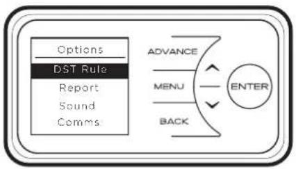
The Options menu allows the settings to be modified to suit the user's preferences. These are;
DST Rule - Select your daylight saving setting. The heater clock will automatically adjust for daylight saving (British Summer Time as it is often referred to). If no adjustment is required then select none.
Report - Service information is displayed.
Sound - Audio feedback can be enabled or disabled.
Comms - Choose to enable or disable Wireless Connectivity. If additional RF Module is connected, user will have option to enable or disable RF communications.
flowchart
graph TD
    A["Options"] --> B["DST Rule"]
    B --> C["Report"]
    C --> D["Sound"]
    D --> E["Comms"]
    F["ADVANCE"] --> G["MENU"]
    G --> H["ENTER"]
    I["BACK"] --> H
Child Lock
In cases where unauthorised persons may tamper with the control settings it is possible to set a tamper-proof feature.
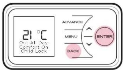
To lock the controls press Back and Enter for two seconds. Child Lock will appear at the bottom of the screen. To unlock the control repeat the action of pressing Back and Enter for two seconds.

NOTE:
The controls cannot be adjusted when child lock is active.
text_image
21 °C Out All Day Comfort On Child Lock ADVANCE MENU BACK ENTERUser Information
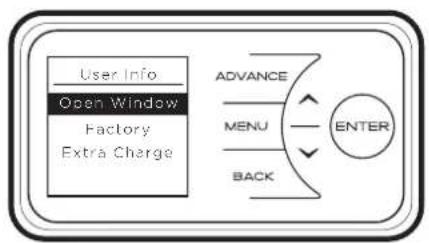
Press and hold Enter for five seconds to enter the User Information menu;
Open Window detection (OW), when enabled, the heater will reduce the target room temperature to limit the energy waste when an open window is detected. Disabled as default.
Factory Reset returns all settings to the factory presets.
Extra Charge - forces an extra charge of up to seven hours during off-peak periods. If the output of the heater is not able to deliver the required comfort level then it is possible to force the heater to store additional energy. In this way more electrical energy is stored during the off-peak period and this will increase comfort levels. Up to seven hours additional off-peak charging can be selected.

NOTE: The extra charge option will lead to more energy being stored during the off peak period, this will lead to higher running costs. Only use this setting when a room is consistently below the required temperature and yo are sure that the timer mode is set up and selected correctly.
flowchart
graph TD
    A["User Info"] --> B["Open Window"]
    B --> C["Factory"]
    C --> D["Extra Charge"]
    D --> E["ADVANCE"]
    E --> F["MENU"]
    F --> G["ENTER"]
    G --> H["BACK"]
Service
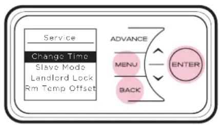
In order to enter the Service menu, Back, Menu & Enter must be pressed simultaneously and held for 10 seconds.
Charge Time - for Service personnel use only.
Slave Mode - for Service personnel use only.
If more than one heater is installed in the same room it is recommended that the smallest capacity heater is set as a Slave.
Disabled as factory default.
Landlord Lock - for User and Service personnel use.
Allows to lock:
- the ability to select or adjust the Timer Mode
- Use of Boost and Setback functions
- Limit maximum operating temperature
Disabled as factory default.
Default code : 0 0 0 0
Rm Temp Offset - for Service personnel use only.
Allows to set a Room Sensor temperature offset. Factory pre-set offset as default.
flowchart
graph TD
    A["Service"] --> B["Change Time"]
    B --> C["Slave Mode"]
    C --> D["Landlord Lock"]
    D --> E["Rm Temp Offset"]
    F["ADVANCE"] --> G["MENU"]
    G --> H["ENTER"]
    H --> I["BACK"]
Landlord Lock Mode
Introduction
This appliance has a built in Landlord lock mode, when this mode is activated all functionality of the Boost and Setback is locked and the user will have no ability to select or adjust timer mode. It is possible to limit the maximum operating temperature in the Landlord mode.
Operation in Landlord Lock Mode
When Landlord Lock mode is active the specific appliance modes are locked, it is not possible for the user to adjust predetermined comfort periods. During these periods the appliance will control the room to a desired temperature. The set point can be adjusted by the user however it is possible to assign a maximum set point limit during the Landlord Lock mode setup. Once the Landlord Lock mode is disabled, the use of Boost and Setback modes and selection/adjustment of timer mode are enabled.
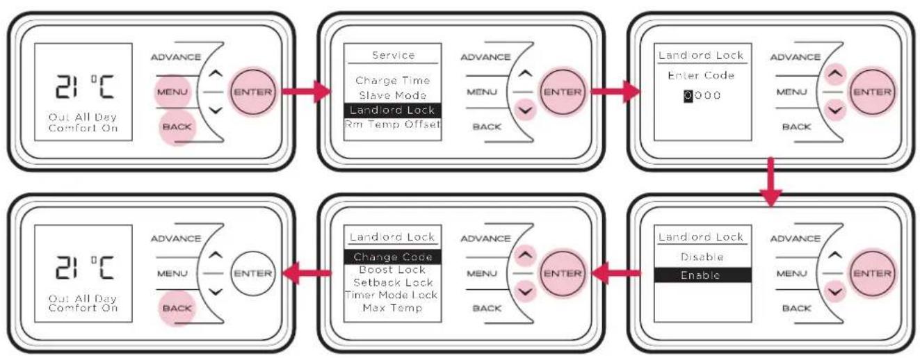
To activate Landlord Lock mode the user must enter service menu first. Back, Menu & Enter must be pressed simultaneously and held for 10 seconds. To access the Landlord Lock menu the user will be prompted to enter the Landlord Lock PIN.
Enabling Landlord Lock Mode
After correct PIN entered, select Enable using Enter. Landlord Lock mode will be enabled, normal functionality of the appliance will be disabled allowing only the functionality determined by Landlord Lock.
Disabling Landlord Lock Mode
After correct PIN entered, select Disable and confirm using Enter. Landlord Lock will be disabled and full appliance functionality will be enabled.
flowchart
graph TD
    A["Out All Day Comfort On"] --> B["Service"]
    B --> C["Landlord Lock"]
    C --> D["Enter Code: 0000"]
    D --> E["Advance Menu: BACK"]
    F["Out All Day Comfort On"] --> G["Service"]
    G --> H["Landlord Lock"]
    H --> I["Enter Code: 0000"]
    I --> J["Advance Menu: BACK"]
    K["Out All Day Comfort On"] --> L["Service"]
    L --> M["Landlord Lock"]
    M --> N["Enter Code: 0000"]
    N --> O["Advance Menu: BACK"]
    P["Out All Day Comfort On"] --> Q["Service"]
    Q --> R["Landlord Lock"]
    R --> S["Enter Code: 0000"]
    S --> T["Advance Menu: BACK"]
    U["Out All Day Comfort On"] --> V["Service"]
    V --> W["Landlord Lock"]
    W --> X["Enter Code: 0000"]
    X --> Y["Advance Menu: BACK"]
    Z["Out All Day Comfort On"] --> AA["Service"]
    AA --> AB["Landlord Lock"]
    AB --> AC["Enter Code: 0000"]
    AC --> AD["Advance Menu: BACK"]
    AE["Out All Day Comfort On"] --> AF["Service"]
    AF --> AG["Landlord Lock"]
    AG --> AH["Enter Code: 0000"]
    AH --> AI["Advance Menu: BACK"]
    AJ["Out All Day Comfort On"] --> AK["Service"]
    AK --> AL["Landlord Lock"]
    AL --> AM["Enter Code: 0000"]
    AM --> AN["Advance Menu: BACK"]
    AO["Out All Day Comfort On"] --> AP["Service"]
    AP --> AQ["Landlord Lock"]
    AQ --> AR["Enter Code: 0000"]
    AR --> AS["Advance Menu: BACK"]
    AT["Out All Day Comfort On"] --> AU["Service"]
    AU --> AV["Landlord Lock"]
    AV --> AW["Enter Code: 0000"]
    AW --> AX["Advance Menu: BACK"]
    AY["Out All Day Comfort On"] --> AZ["Service"]
    AZ --> BA["Landlord Lock"]
    BA --> BB["Enter Code: 0000"]
    BB --> BC["Advance Menu: BACK"]
    BD["Out All Day Comfort On"] --> BE["Service"]
        BE --> BF["Landlord Lock"]
    BF --> BG["Enter Code: 0000"]
    BG --> BH["Advance Menu: BACK"]
    BI["Out All Day Comfort On"] --> BJ["Service"]
        BJ --> BK["Landlord Lock"]
    BK --> BL["Enter Code: 0000"]
    BL --> BM["Advance Menu: BACK"]
    BN["Out All Day Comfort On"] --> BO["Service"]
        BO --> BP["Landlord Lock"]
    BP --> BQ["Enter Code: 0000"]
    BQ --> BR["Advance Menu: BACK"]
    BS["Out All Day Comfort On"] --> BT["Service"]
        BT --> BU["Landlord Lock"]
    BU --> BV["Enter Code: 0000"]
    BV --> BW["Advance Menu: BACK"]
    BX["Out All Day Comfort On"] --> BY["Service"]
        BY --> BZ["Landlord Lock"]
    BZ --> CA["Enter Code: 0000"]
    CA --> CB["Advance Menu: BACK"]

NOTE:
The default PIN is 0000,
the password can be changed from
within the Landlord Lock mode menu.
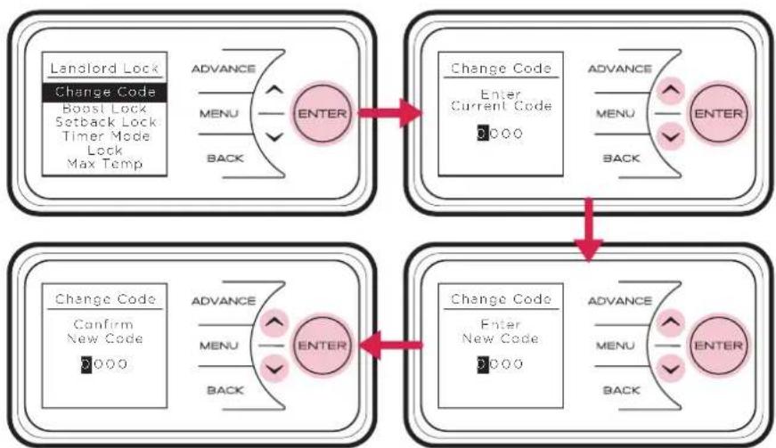
Change Code - Allows to customise the Landlord Lock code Default Code: 0 0 0 0
Boost - Allows to Enable or Disable the Boost function lock. Enabled by default
Setback - Allows to Enable or Disable the Setback function lock. Enabled by default.
Timer Mode - Allows Enable/Disable selection or adjustment of the Timer Mode. Enabled by default.
Max Temp - Allows to limit a maximum operation temperature. Set to 26°C by default.
Landlord Lock Mode Settings
Changing the PIN
It is possible to set a user defined Landlord Lock PIN code. Once changed, the PIN code will be required to access the Landlord Lock mode menus.
To change the PIN code select "Change Code" from the main Landlord Lock menu. To complete the change, follow the on-screen instructions, it will be necessary to input the current PIN and then set the new PIN code.
flowchart
graph TD
    A["Landlord Lock\nChange Code\nBoost Lock\nSetback Lock\nTimer Mode\nLock\nMax Temp"] --> B["ENTER"]
    C["Change Code\nEnter\nCurrent Code\n0000"] --> D["ENTER"]
    E["Change Code\nConfirm\nNew Code\n0000"] --> F["ENTER"]
    G["Change Code\nEnter\nNew Code\n0000"] --> H["ENTER"]
    I["Advance"] --> J["MENU"]
    K["BACK"] --> L["ENTER"]
    M["Advance"] --> N["MENU"]
    O["BACK"] --> P["ENTER"]
Boost, Setback and Timer Mode Lock
It is possible to activate Boost, Setback and Timer Mode lock, this ensures that when the Landlord lock is enabled, normal functionality of the appliance will be disabled allowing only the functionality determined by Landlord lock.
These locks can be enabled or disabled from within the Landlord lock settings menu.

flowchart
graph LR
    A["Landlord Lock\nChange Code\nBoost Lock\nSetback Lock\nTimer Mode\nLock\nMax Temp"] --> B["Advance\nMENU\nBACK"]
    B --> C["ENTER"]
    C --> D["Boost Lock\nDisable\nEnable\nSettings Lock"]
    D --> E["Advance\nMENU\nBACK"]
    E --> F["ENTER"]
    F --> G["Boost Lock\n✓\nEnabled"]
    G --> H["Advance\nMENU\nBACK"]
    H --> I["ENTER"]
Maximum Temperature
A maximum temperature limit for the room during Landlord lock mode can be applied. This will restrict the users ability to increase the room temperature beyond a set value. The maximum temperature can be set by selecting 'Max Temp.' in the Landlord lock settings menu. The temperature can be adjusted using the arrow keys and then confirmed using the Enter key.
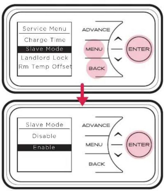
Slave Mode
If more than one heater is installed in the same room it is recommended that the largest capacity heater is set as the master and all smaller capacity products are set as slaves.
Press Menu, Back and Enter for 3 seconds to enter the service menu, select 'Slave Mode' and press Enter. Select 'Enable'.
flowchart
graph TD
    A["Service Menu\nCharge Time\nSlave Mode\nLandlord Lock\nRm Temp Offset"] --> B["ADVANCE"]
    B --> C["MENU"]
    B --> D["BACK"]
    E["Slave Mode\nDisable\nEnable"] --> F["ADVANCE"]
    F --> G["MENU"]
    F --> H["BACK"]
    I["ENTER"] --> J["ADVANCE"]
    J --> K["MENU"]
    J --> L["BACK"]
Energy Saving Tips
The energy we use to heat, light and power our homes contributes over a quarter of the UK's carbon emissions, the principle contributor to climate change. Around half the energy used in the home is for heating and hot water, so using your heating system efficiently will not only help the environment, but also save you money.
Energy efficiency tips for heating and hot water
1. Don't set the temperature to high...
By reducing the thermostat setting by just 1°C can reduce your energy use by as much as 10%. And if you're going away during the winter, leave the thermostat on the frost protection setting to provide protection from freezing at a minimum cost.
2. Use it where you need it...
Set the appropriate temperature on your heaters for the room they are in; for example, leave the thermostat on a heater in a spare bedroom on a lower setting.
3. Use it when you need it...
Use heaters fitted with timers or linked to central controllers to turn the heating on only when you need it and automatically switch it off when you don't.
4. Curtains
Close your curtains at dusk to stop heat escaping through the windows.
5. Windows
Nearly 25% of heat loss can occur through poorly insulated frames and single glazing. If you can't afford to double glaze all your windows, go for the rooms you heat most.
6. Treat your hot water tank...
Give it a jacket An insulating jacket for hot water tanks costs only a few pounds and pays for itself within months. Fit one that's at least 75mm (3") thick and you could save £10-15 a year.
7. Water
Use a shower if you have one to save time, money and water. Don't set the thermostat too high on your water heater - 60°C/140°F is usually adequate for bathing and washing. Put the plug in when running hot water in your sink - leaving hot taps running is both wasteful and expensive. Ensuring dripping taps are repaired quickly. In just one day, you could waste enough water to fill a bath.
Other Energy Saving Tips for Around the Home
1. Lights
Turn off lights whenever you leave a room for more than ten minutes. Use low-energy bulbs wherever you can as they use less than a quarter of the electricity used by ordinary light bulbs and last ten times longer!
2. Cooking
Use the right size pan for food and cooker hob. Keep saucepan lids on - this enables you turn down the heat. Boil water for cooking in a kettle first.
Important
During the initial operation, some odour may be noticed due to the newness of materials used in manufacture. This is normal and will disappear after a short period of use. It is however advisable to keep the room well ventilated.
Cleaning
WARNING - ALWAYS ISOLATE THE POWER SUPPLY BEFORE CLEANING THE HEATER.
Before commencing cleaning allow the heater to cool. The outside can be cleaned by wiping it over with a dry cloth. Do not use abrasive cleaning powders or furniture polish, as this can damage the surface finish.
Discolouration of wall finishes can sometimes occur immediately above a heater due to the properties of some paints and decorating materials or the presence of environmental impurities in the air (such as soot, cigarette smoke or incense generated from the burning of candles, etc.). A suitable shelf (available from Dimplex) may be fitted to limit the extent of any wall discolouration.
Recycling

For electrical products sold within the European Community. At the end of the electrical products useful life it should not be disposed of with household waste. Please recycle where facilities exist. Check with a Local Authority or retailer for recycling advice in your country. Packaging should be recycled where possible.
Warranty
What does a Dimplex Warranty cover?
Dimplex products deliver reliable service for normal, household use in domestic settings. All Dimplex products are individually tested before leaving the factory.
If you are a consumer and you experience a problem with your Dimplex product, which is found to be defective due to faulty materials or workmanship within the Warranty Period, this Dimplex Warranty will cover repair or - at the discretion of Dimplex - replacement with a functionally equivalent Dimplex product.
The Dimplex Warranty Period is two calendar years from the date of purchase of your Dimplex product, or the date of delivery of the product, if later. The Dimplex Warranty is conditional upon you providing the original purchase receipt as proof of purchase. Please therefore retain your receipt as proof of purchase.
If you do experience a problem with your Dimplex product please call the Helpline on +44 [0]344 879 3588 or visit https://www.dimplex.co.uk/support. For ROI please email serviceireland@glendimplex.com or call +353(0)1842 833. We will need details of your Dimplex product, its serial number and a description of the fault which has occurred. You can find the model number and serial number for your Dimplex product on the heaters side. Once we receive your information and proof of purchase we will contact you to make the necessary arrangements.
If your Dimplex product is not covered by this Dimplex Warranty there may be a charge to repair your product. However, we will contact you for agreement to any charges before any chargeable service is carried out.
What is not covered by a Dimplex Warranty?
The Dimplex Warranty does not cover any of the following:
- Any fault or damage to your Dimplex product due to faulty materials or workmanship occurring outside the two-year Warranty Period.
- Any fault or damage occurring to any pre-owned Dimplex product or to any other equipment or property.
- Accidental damage to your Dimplex product or damage to your Dimplex product from external sources (for example, transit, weather, electrical outages or power surges).
- Fault or damage to your Dimplex product which is:
- Not due to faulty materials or workmanship or which is due to circumstances outside Dimplex's control.
- Caused by use of your Dimplex product for anything other than normal domestic household purposes in the country where it was purchased.
- Caused by any misuse, abuse or negligent use of the Dimplex product, including but not limited to any failure to use it in accordance with the Operating Instructions supplied with the product.
- Caused by any failure to assemble, install clean and maintain your Dimplex product in accordance with the Operating Instructions supplied with the product unless this was carried out by Dimplex or its authorised dealers.
- Caused by repairs or alterations to your Dimplex product not carried out by Dimplex service personnel or its authorised dealer(s).
- Caused by use of any consumables or spare parts for your Dimplex product which are not Dimplex - specified.
Terms and Conditions
- The Dimplex Warranty is valid for Dimplex from the date of purchase of your Dimplex product from a recognised retailer in the country of purchase and use, or the date of delivery of the product if later, always provided the original receipt has been retained and is produced as proof of purchase.
- You must provide to Dimplex or its authorised agents on request the original receipt as proof of purchase and - if required by Dimplex - proof of delivery. If you are unable to provide this documentation, you will be required to pay for any repair work required.
- Any repair work under the Dimplex Warranty will be carried out by Dimplex or its authorised dealer(s) and any parts that are replaced will become the property of Dimplex. Any repairs performed under the Dimplex Warranty will not extend the Warranty Period.
- Any replacement of your Dimplex product by Dimplex during the Warranty Period will start the two-year Warranty Period afresh from the date of delivery of the replacement Dimplex product to you.
- The Dimplex Warranty does not entitle you to recovery of any indirect or consequential loss or damage including but not limited to loss or damage to any other property.
- The Dimplex Warranty is in addition to your statutory rights as a consumer and your statutory rights are not affected by this Dimplex Warranty.
Battery Replacement
Fig. 17
natural_image
Technical line drawing of a mechanical component with a red rotation arrow indicating motion (no text or symbols)Fig. 18
natural_image
Technical line drawing of a device housing with internal components and a separate handle (no text or symbols)Fig. 19
natural_image
Technical line drawing of a mechanical housing or enclosure with internal components and a red arrow indicating direction (no text or symbols present)Fig. 20
natural_image
Technical line drawing of a mechanical component with a red arrow indicating a feature (no text or symbols present)
NOTE:
Battery should be disposed
of in an appropriate manner
IMPORTANT: Before replacing the battery ensure the heater is isolated from the electricity supply.
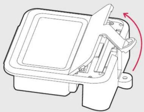
This product is fitted with a replaceable battery in the controls. To replace the battery, follow the steps below.
- Unscrew the cover of the user interface and pivot away from the housing as shown in Fig. 17. Set the cover and the screw safely to one side.
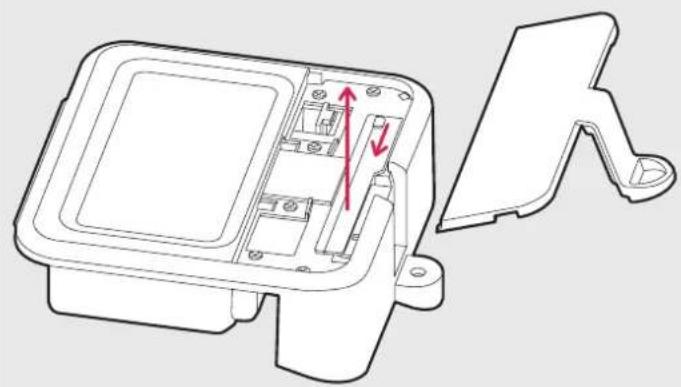
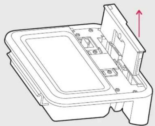
- Slide the catch and pull the module up from the User Interface as shown in Fig. 18
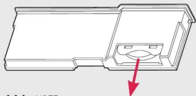
- Move the module clear of the User Interface to access the battery, Fig. 19
- Remove the coin cell battery and replace.
- Slide the module back into the User Interface, ensuring the catch in engaged
- Replace the cover and secure using the screw
Clean the outlet grilles and adjacent surfaces after the first operation as some dust may be produced when the heater is first used
Energy Related Product Directive
This product complies with Lot20 of the Energy Efficiency Directive (2015/1188).
| Model Identifier(s): | XLE050 | XLE070 | XLE100 | XLE125 | XLE150 | Unit | |
| Heat output | |||||||
| Nominal heat output Pnom 0.5 0.75 1.0 1.25 1.5 kW | |||||||
| Minimum heat output (indicative) | Pmin 0.0 0.0 0.0 0.0 0.0 kW | ||||||
| Maximum continuous heat output | Pmax,c | 0.8 | 1.0 | 1.2 | 1.4 | 1.6 | kW |
Type of heat input for electric storage local space heaters
| Electronic heat charge control with room temperature feedback | Yes |
Type of heat output / room temperature control
| Electronic room temperature control plus 7 day timer Yes |
Contact details
Glen Dimplex Heating and Ventilation
Millbrook House, Grange Drive, Hedge End, Southampton, SO30 2DF
Tel: 0344 879 3588
This product complies with Lot20 of the Energy Efficiency Directive (2015/1188).
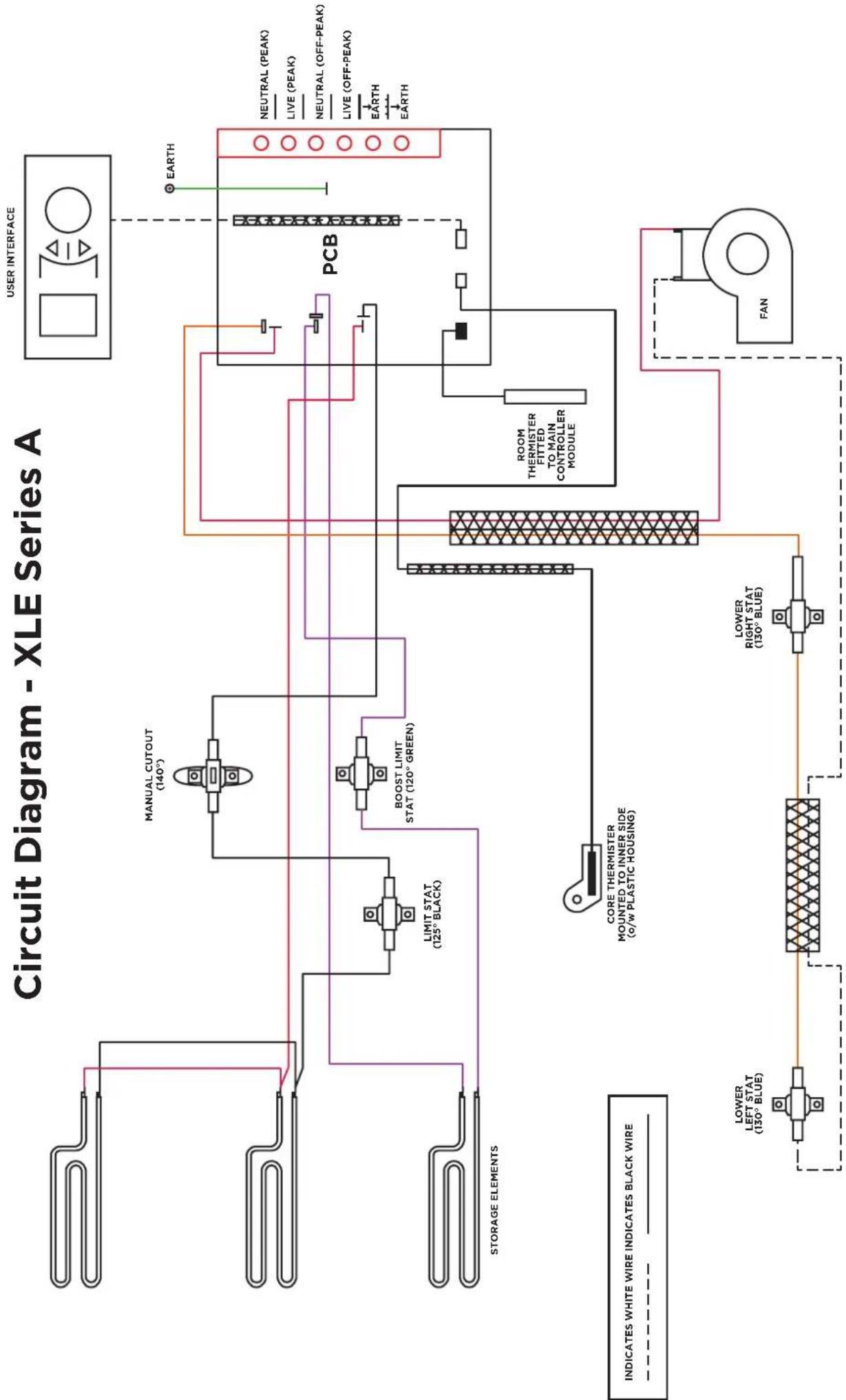
flowchart
graph TD
    A["Storage Elements"] --> B["LIMIT STAT (125° BLACK)"]
    B --> C["BOOST LIMIT STAT (120° GREEN)"]
    C --> D["PCB"]
    D --> E["FAN"]
    E --> F["LOWER LEFT STAT (130° BLUE)"]
    E --> G["LOWER RIGHT STAT (130° BLUE)"]
    H["NEUTRAL (PEAK)"] --> I["EARTH"]
    J["LIVE (PEAK)"] --> K["EARTH"]
    L["NEUTRAL (OFF-PEAK)"] --> M["EARTH"]
    N["LIVE (OFF-PEAK)"] --> O["EARTH"]
    P["UNDERWIRE"] --> Q["EARTH"]
    R["UNDERWIRE"] --> S["EARTH"]
    T["UNDERWIRE"] --> U["EARTH"]
    V["UNDERWIRE"] --> W["EARTH"]
    X["UNDERWIRE"] --> Y["EARTH"]
    Z["UNDERWIRE"] --> AA["EARTH"]
    AB["UNDERWIRE"] --> AC["EARTH"]
    AD["UNDERWIRE"] --> AE["EARTH"]
    AF["UNDERWIRE"] --> AG["EARTH"]
    AH["UNDERWIRE"] --> AI["EARTH"]
    AJ["UNDERWIRE"] --> AK["EARTH"]
    AL["UNDERWIRE"] --> AM["EARTH"]
    AN["UNDERWIRE"] --> AO["EARTH"]
    AP["UNDERWIRE"] --> AQ["EARTH"]
    AR["UNDERWIRE"] --> AS["EARTH"]
DCDimplex®
Customer Helpline: 0344 879 3588
aftersales@dimplex.co.uk
www.dimplex.co.uk
Glen Dimplex Heating and Ventilation
Millbrook House, Grange Drive, Hedge End, Southampton, SO30 2DF